WO2017002529A1 - 電力変換制御装置、バッテリ制御装置、駆動制御サブシステム - Google Patents
電力変換制御装置、バッテリ制御装置、駆動制御サブシステム Download PDFInfo
- Publication number
- WO2017002529A1 WO2017002529A1 PCT/JP2016/066530 JP2016066530W WO2017002529A1 WO 2017002529 A1 WO2017002529 A1 WO 2017002529A1 JP 2016066530 W JP2016066530 W JP 2016066530W WO 2017002529 A1 WO2017002529 A1 WO 2017002529A1
- Authority
- WO
- WIPO (PCT)
- Prior art keywords
- control device
- battery
- power conversion
- state
- current
- Prior art date
- Legal status (The legal status is an assumption and is not a legal conclusion. Google has not performed a legal analysis and makes no representation as to the accuracy of the status listed.)
- Ceased
Links
Images


Classifications
-
- G—PHYSICS
- G01—MEASURING; TESTING
- G01R—MEASURING ELECTRIC VARIABLES; MEASURING MAGNETIC VARIABLES
- G01R31/00—Arrangements for testing electric properties; Arrangements for locating electric faults; Arrangements for electrical testing characterised by what is being tested not provided for elsewhere
- G01R31/36—Arrangements for testing, measuring or monitoring the electrical condition of accumulators or electric batteries, e.g. capacity or state of charge [SoC]
-
- B—PERFORMING OPERATIONS; TRANSPORTING
- B60—VEHICLES IN GENERAL
- B60L—PROPULSION OF ELECTRICALLY-PROPELLED VEHICLES; SUPPLYING ELECTRIC POWER FOR AUXILIARY EQUIPMENT OF ELECTRICALLY-PROPELLED VEHICLES; ELECTRODYNAMIC BRAKE SYSTEMS FOR VEHICLES IN GENERAL; MAGNETIC SUSPENSION OR LEVITATION FOR VEHICLES; MONITORING OPERATING VARIABLES OF ELECTRICALLY-PROPELLED VEHICLES; ELECTRIC SAFETY DEVICES FOR ELECTRICALLY-PROPELLED VEHICLES
- B60L3/00—Electric devices on electrically-propelled vehicles for safety purposes; Monitoring operating variables, e.g. speed, deceleration or energy consumption
-
- B—PERFORMING OPERATIONS; TRANSPORTING
- B60—VEHICLES IN GENERAL
- B60L—PROPULSION OF ELECTRICALLY-PROPELLED VEHICLES; SUPPLYING ELECTRIC POWER FOR AUXILIARY EQUIPMENT OF ELECTRICALLY-PROPELLED VEHICLES; ELECTRODYNAMIC BRAKE SYSTEMS FOR VEHICLES IN GENERAL; MAGNETIC SUSPENSION OR LEVITATION FOR VEHICLES; MONITORING OPERATING VARIABLES OF ELECTRICALLY-PROPELLED VEHICLES; ELECTRIC SAFETY DEVICES FOR ELECTRICALLY-PROPELLED VEHICLES
- B60L58/00—Methods or circuit arrangements for monitoring or controlling batteries or fuel cells, specially adapted for electric vehicles
- B60L58/10—Methods or circuit arrangements for monitoring or controlling batteries or fuel cells, specially adapted for electric vehicles for monitoring or controlling batteries
- B60L58/12—Methods or circuit arrangements for monitoring or controlling batteries or fuel cells, specially adapted for electric vehicles for monitoring or controlling batteries responding to state of charge [SoC]
-
- H—ELECTRICITY
- H01—ELECTRIC ELEMENTS
- H01M—PROCESSES OR MEANS, e.g. BATTERIES, FOR THE DIRECT CONVERSION OF CHEMICAL ENERGY INTO ELECTRICAL ENERGY
- H01M10/00—Secondary cells; Manufacture thereof
- H01M10/42—Methods or arrangements for servicing or maintenance of secondary cells or secondary half-cells
- H01M10/48—Accumulators combined with arrangements for measuring, testing or indicating the condition of cells, e.g. the level or density of the electrolyte
-
- H—ELECTRICITY
- H02—GENERATION; CONVERSION OR DISTRIBUTION OF ELECTRIC POWER
- H02J—ELECTRIC POWER NETWORKS; CIRCUIT ARRANGEMENTS OR SYSTEMS FOR SUPPLYING OR DISTRIBUTING ELECTRIC POWER; SYSTEMS FOR STORING ELECTRIC ENERGY
- H02J7/00—Circuit arrangements for charging or discharging batteries or for supplying loads from batteries
-
- Y—GENERAL TAGGING OF NEW TECHNOLOGICAL DEVELOPMENTS; GENERAL TAGGING OF CROSS-SECTIONAL TECHNOLOGIES SPANNING OVER SEVERAL SECTIONS OF THE IPC; TECHNICAL SUBJECTS COVERED BY FORMER USPC CROSS-REFERENCE ART COLLECTIONS [XRACs] AND DIGESTS
- Y02—TECHNOLOGIES OR APPLICATIONS FOR MITIGATION OR ADAPTATION AGAINST CLIMATE CHANGE
- Y02E—REDUCTION OF GREENHOUSE GAS [GHG] EMISSIONS, RELATED TO ENERGY GENERATION, TRANSMISSION OR DISTRIBUTION
- Y02E60/00—Enabling technologies; Technologies with a potential or indirect contribution to GHG emissions mitigation
- Y02E60/10—Energy storage using batteries
-
- Y—GENERAL TAGGING OF NEW TECHNOLOGICAL DEVELOPMENTS; GENERAL TAGGING OF CROSS-SECTIONAL TECHNOLOGIES SPANNING OVER SEVERAL SECTIONS OF THE IPC; TECHNICAL SUBJECTS COVERED BY FORMER USPC CROSS-REFERENCE ART COLLECTIONS [XRACs] AND DIGESTS
- Y02—TECHNOLOGIES OR APPLICATIONS FOR MITIGATION OR ADAPTATION AGAINST CLIMATE CHANGE
- Y02T—CLIMATE CHANGE MITIGATION TECHNOLOGIES RELATED TO TRANSPORTATION
- Y02T10/00—Road transport of goods or passengers
- Y02T10/60—Other road transportation technologies with climate change mitigation effect
- Y02T10/70—Energy storage systems for electromobility, e.g. batteries
Definitions
- the present invention relates to a power conversion control device, a battery control device, and a drive control subsystem including these.
- a battery system including a load (motor), an inverter, a converter, a power receiving unit, a main power source, a sub power source, and a power source switch is known (Patent Document 1).
- the load driving time reaches a predetermined correction start time
- the battery system measures the voltage between the terminals when the main power supply is charged / discharged with a preset inspection current, and based on the measured value. Then, an error in the state of charge (SOC) of the battery obtained by current integration is corrected.
- SOC state of charge
- a power conversion control device is connected to a battery control device that controls charging and discharging of a battery, and controls a power conversion circuit that supplies an AC current to a motor using a DC current supplied from the battery.
- a permission signal for permitting the start of error correction for the state of charge of the battery detected by the battery control device is transmitted to the battery control device.
- a battery control apparatus controls charging / discharging of a battery that supplies a direct current for generating an alternating current supplied to a motor from a power conversion circuit to the power conversion circuit.
- a state is detected, and when the current value of the direct current is 0 or 0, error correction for the state of charge of the battery is performed.
- a drive control subsystem includes the power conversion control device and the battery control device described above.
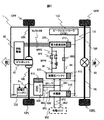
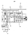
- FIG. 1 is a diagram showing a configuration of an electric vehicle 1 equipped with a power conversion control device and a battery control device according to an embodiment of the present invention.
- the electric vehicle 1 is an example of an electric vehicle having a general configuration.
- the electric vehicle 1 shows an example of front wheel drive, but it may be a rear wheel drive or a four wheel drive vehicle.
- the rotating electrical machine 30 is mechanically connected to the axles 40R and 40L via the gear box 40.
- the axles 40R and 40L are connected to driving wheels (front wheels) 10FR and 10RL, respectively.
- the drive wheels 10FR and 10RL drive the electric vehicle by transmitting the output of the rotating electrical machine 30 via the gear box 40 and the axles 40R and 40L to the ground as a driving force.
- the driven wheels (rear wheels) 10RR and 10RL are connected to the differential gear 60 by axles 70L and 70R, respectively.
- the vehicle controller (VCM) 100 is a controller that controls the electric vehicle 1 in an integrated manner.
- the vehicle controller 100 is connected to a power conversion control unit (MCU) 210, a battery control unit (BCU) 410, a charger control unit 510, and a converter control unit 610 through a CAN communication BUS line 110.
- MCU power conversion control unit
- BCU battery control unit
- a charger control unit 510 charger control unit 510
- converter control unit 610 a controller that controls the electric vehicle 1 in an integrated manner.
- CAN communication BUS line 110 CAN communication BUS line 110.
- the power conversion control device 210 is connected to the power conversion circuit 220.
- the power conversion circuit 220 is connected to the rotating electrical machine 30 by the three-phase harnesses 9U, 9V, and 9W, and can exchange AC power with the rotating electrical machine 30 through these.
- the power conversion circuit 220 is connected to the high voltage battery 420 by the DC harnesses 9P and 9N, and can exchange DC power with the high voltage battery 420 through the DC harnesses 9P and 9N. Yes.
- the DC harness 9P includes a positive electrode relay 9PS, a precharge resistor 9PPR, and a precharge relay 9PPS.
- the precharge resistor 9PPR and the precharge relay 9PPS are connected in series, and these are attached in parallel with the positive electrode relay 9PS.
- the DC harness 9P can connect and disconnect the DC power supplied from the high voltage battery 420 at any time by switching the connection state of the positive electrode relay 9PS and the precharge relay 9PPS.
- the DC harness 9N includes a negative relay 9NS. The DC harness 9N can connect and disconnect the DC power supplied from the high voltage battery 420 at any time by switching the connection state of the negative relay 9NS.
- the battery control device 410 is connected to the high voltage battery 420.
- the high voltage battery 420 is connected to the charger 500 by harnesses 9P1 and 9N1, and can exchange DC power with the charger 500 through these.
- the charger controller 510 is connected to the charger 500.
- the charger 500 is connected to harnesses 9P3 and 9N3 for connection to a charging stand 800 that is an external power source.
- the charger control device 510 controls the electric power from the charging stand 800, whereby the high voltage battery 420 is charged.
- the charger 500 has a power supply function, the power of the high voltage battery 420 can be supplied to the outside.
- Converter control device 610 is connected to DCDC converter 600.
- the DCDC converter 600 is connected to the high voltage battery 420 by the harnesses 9P2 and 9N2 connected to the harnesses 9P1 and 9N1, respectively.
- the DC power supplied from the high voltage battery 420 can be appropriately converted by the DCDC converter 600 and output to the low voltage battery 700.
- the low voltage battery 700 has an output voltage of about 12 to 24V, for example.
- the low voltage battery 700 is connected to the DCDC converter 600 and is appropriately charged with the DC power from the DCDC converter 600.
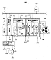
- FIG. 2 is a diagram showing a configuration of a vehicle drive system according to an embodiment of the present invention.
- the vehicle drive system of FIG. 2 includes the rotating electrical machine 30, the vehicle controller 100, the charger 500, the charger control device 510, the DCDC converter 600, the converter control device 610, the low voltage battery 700, the power conversion device 200, and the battery of FIG. Device 400.
- the power conversion device 200 includes the power conversion control device 210 and the power conversion circuit 220 in FIG. 1, the smoothing capacitor 200C, and the current sensor 20C.
- the battery device 400 includes the battery control device 410, the high voltage battery 420, and the DC harnesses 9P and 9N shown in FIG.
- the power conversion control device 210 and the battery control device 410 may be collectively referred to as a drive control subsystem.
- the vehicle controller 100 transmits a start command to the BUS line 110 of CAN communication.
- the power conversion control device 210 and the battery control device 410 receive the start command transmitted from the vehicle controller 100 from the BUS line 110, the power conversion control device 210 and the battery control device 410 each start a predetermined start sequence.
- the battery control device 410 starts the startup sequence, SOC detection error correction and initial SOC value detection described later are performed. Subsequently, the negative relay 9NS is turned on (connected), and then the precharge relay 9PPS is turned on (connected). Thus, conduction between the high voltage battery 420 and the power conversion circuit 220 is started, and a charging current flows to the smoothing capacitor 200C through the precharge resistor 9PPR. Thereafter, when the voltage across the smoothing capacitor 200C reaches a certain value or more, the positive relay 9PS is turned on (connected) and the precharge relay 9PPS is turned off (disconnected). This operation is for preventing an excessive inrush current from flowing through the smoothing capacitor 200C.
- the vehicle controller 100 transmits an end command to the BUS line 110 of CAN communication.
- the power conversion control device 210 and the battery control device 410 receive the end command transmitted from the vehicle controller 100 from the BUS line 110, the power conversion control device 210 and the battery control device 410 each start a predetermined end sequence.
- the battery control device 410 starts an end sequence, the negative relay 9NS and the positive relay 9PS are turned off (disconnected), and the high voltage battery 420 is disconnected from the power conversion circuit 220.
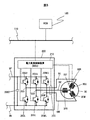
- FIG. 3 is a diagram showing details of the rotating electrical machine 30 and the power conversion device 200.
- the power conversion circuit 220 converts a direct current (DC power) supplied from the high voltage battery 420 into an alternating current (AC power) and supplies it to the rotating electrical machine 30 under the control of the power conversion control device 210.
- the power conversion circuit 220 can also charge the high voltage battery 420 by converting AC power generated by the rotation of the rotating electrical machine 30 into DC power.
- the power conversion circuit 220 includes three-phase upper arm switching elements 20UU, 20VU, and 20WU corresponding to the U-phase, V-phase, and W-phase, and three-phase lower-arm switching corresponding to the U-phase, V-phase, and W-phase, respectively. It has elements 20UL, 20VL, and 20WL. These switching elements are composed of, for example, IGBTs or MOSFETs.
- Harness 9U electrically connects U-phase coil 30U of rotating electrical machine 30 and U-phase connection terminal 20U of power conversion circuit 220.
- U-phase connection terminal 20U is provided between U-phase upper arm switching element 20UU and U-phase lower arm switching element 20UL.
- the harness 9V electrically connects the V-phase coil 30V of the rotating electrical machine 30 and the V-phase connection terminal 20V of the power conversion circuit 220.
- V-phase connection terminal 20V is provided between V-phase upper arm switching element 20VU and V-phase lower arm switching element 20VL.
- the harness 9W electrically connects the W-phase coil 30W of the rotating electrical machine 30 and the W-phase connection terminal 20W of the power conversion circuit 220.
- W-phase connection terminal 20W is provided between W-phase upper arm switching element 20WU and W-phase lower arm switching element 20WL.
- the rotating electrical machine 30 converts an electrical output into a mechanical output by rotationally driving a rotor (not shown) using AC power input from the power conversion circuit 220 via the harnesses 9U, 9V, and 9W (power running). . Further, when the rotor is rotated by applying mechanical input to the rotating electrical machine 30 from the outside, the rotating electrical machine 30 acts as a generator, and electrical output is possible (regeneration).
- the magnetic pole position sensor 30R detects the rotor magnetic pole position of the rotating electrical machine 30. Information on the rotor magnetic pole position detected by the magnetic pole position sensor 30R is output to the power conversion control device 210.
- the thermistor 30 ⁇ / b> T detects the coil temperature of the rotating electrical machine 30. Information on the coil temperature detected by the thermistor 30T is output to the power conversion control device 210.
- the current sensor 20 ⁇ / b> C is attached to the harnesses 9 ⁇ / b> U, 9 ⁇ / b> V, and 9 ⁇ / b> W, and detects a current value flowing between the power conversion circuit 220 and the rotating electrical machine 30. Information on the current of each phase detected by the current sensor 20 ⁇ / b> C is output to the power conversion control device 210.
- the switching operation of the six switching elements 20UU, 20UL, 20VU, 20VL, 20WU, and 20WL of the power conversion circuit 220 is performed according to the magnetic pole position of the rotor under the control of the power conversion control device 210. I do. Thereby, the three-phase AC power having the necessary phase and amplitude is supplied to the U-phase coil 30U, the V-phase coil 30V, and the W-phase coil 30W of the rotating electrical machine 30, respectively. Then, the rotating electrical machine 30 converts the input AC power into a machine output and outputs it. At this time, the power conversion control device 210 performs feedback control based on the detection result of the current that actually flows through the rotating electrical machine 30, thereby controlling the alternating current with the target current value to flow stably through the rotating electrical machine 30.
- the power conversion control device 210 can also monitor the coil temperature of the rotating electrical machine 30 detected by the thermistor 30T and perform control based on the monitoring result. For example, when the coil temperature exceeds a certain threshold value, the AC power input to the rotating electrical machine 30 is limited to a predetermined value or less in order to prevent the rotating electrical machine 30 from burning out.
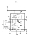
- FIG. 4 is a diagram showing details of the battery device 400.
- the high voltage battery 420 outputs DC power to the power conversion device 200 or inputs DC power from the power conversion device 200 via the DC harnesses 9P and 9N.
- the positive relay 9PS, the negative relay 9NS, the precharge relay 9PPS, and the precharge resistor 9PPR are stored in the battery device 400 is shown, but these may be arranged outside the high voltage battery 420. is there.
- the harnesses 9P1 and 9N2 electrically connect the high voltage battery 420, the charger 500, and the DCDC converter 600.
- the high voltage battery 420 includes n battery cells 420 (1) to 420 (n). n is an arbitrary integer of 1 or more. In the high voltage battery 420 of the present embodiment, all of the battery cells 420 (1) to 420 (n) may be connected in series or in parallel. Moreover, it is good also as a combination of series and parallel.
- One or a plurality of temperature sensors are attached to the high voltage battery 420, and battery temperature information detected by the temperature sensors is input to the battery control device 410.
- the voltmeter 400V measures the total voltage of the high voltage battery 420.
- the voltmeter 400V may measure the total voltage of the high voltage battery 420 by detecting and adding the voltages of the battery cells 420 (1) to 420 (n), or simply measure the battery cell 420 (1).
- the total voltage of the high-voltage battery 420 may be measured by measuring the voltage between the positive electrode and the negative electrode of 420 (n).
- the ammeter 400 ⁇ / b> A measures a current input / output to / from the high voltage battery 420.
- Information on the total voltage of the high-voltage battery 420 detected by the voltmeter 400V and information on the current of the high-voltage battery 420 detected by the ammeter 400A are input to the battery control device 410.
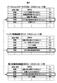
- FIG. 5 is a diagram illustrating an example of a conventional CAN message transmitted / received among the vehicle controller 100, the battery control device 410, and the power conversion control device 210.
- an ID for identification is assigned to each transmission / reception message.
- the vehicle controller 100 transmits a message of the target torque (ID: 010) in the transmission message list to the BUS line 110 of CAN communication at an arbitrary time interval. Since the message reception list of the power conversion control device 210 has the target torque (ID: 010), the power conversion control device 210 receives the message of the target torque. Then, the torque of the rotating electrical machine 30 is controlled based on the target torque value indicated by the received message.
- the battery control device 410 transmits a message of the battery state (ID: 040) in the transmission message list to the BUS line 110 of CAN communication at an arbitrary time interval. Since there is a battery state (ID: 040) in the message reception list of the vehicle controller 100, the vehicle controller 100 receives this battery state message and uses it for controlling the electric vehicle 1.
- the battery status (ID: 400) message includes, for example, battery power (charge / discharge) information, battery total voltage information, battery current information, battery SOC information, battery temperature information, and the like. .
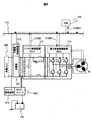
- FIG. 6 is a diagram illustrating an example of conventional CAN message transmission / reception in the vehicle controller 100, the battery control device 410, and the power conversion control device 210.
- the actual signal flow in the transmission / reception of the CAN message described above with reference to FIG. 5 will be described below with reference to FIG.
- the message of the target torque (ID: 010) shown in FIG. 5 is output as indicated by an arrow 110AS.
- the target torque message flows on the CAN communication BUS line 110 and is input to the power conversion control device 210 as indicated by an arrow 110AR.
- the battery control device 410 outputs a message of the battery state (ID: 040) shown in FIG. 5 as indicated by an arrow 410AS.
- the battery status message flows on the CAN communication BUS line 110 and is input to the vehicle controller 100 as indicated by an arrow 410AR.
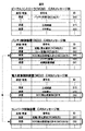
- FIG. 7 is a diagram illustrating an example of a CAN message of an SOC detection error correction request signal transmitted / received among the vehicle controller 100, the battery control device 410, and the power conversion control device 210.
- the battery control device 410 transmits a message of SOC detection error correction request (ID: 042) in the transmission message list to the BUS line 110 of CAN communication. Since the message reception list of the vehicle controller 100 and the message reception list of the power conversion control device 210 include an SOC detection error correction request (ID: 042), the vehicle controller 100 and the power conversion control device 210 perform the SOC detection error correction. Each request message is received. Thereby, the vehicle controller 100 and the power conversion control device 210 can respectively know that the battery control device 410 requests correction of the SOC detection error.
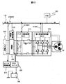
- FIG. 8 is a diagram illustrating an example of CAN message transmission / reception of an SOC detection error correction request signal in the vehicle controller 100, the battery control device 410, and the power conversion control device 210.
- the actual signal flow in the transmission / reception of the CAN message described above with reference to FIG. 7 will be described below with reference to FIG.
- the SOC detection error correction request (ID: 042) message shown in FIG. 7 is output as indicated by an arrow 410BS.
- the SOC detection error correction request message flows on the BUS line 110 of CAN communication, and is input to the power conversion control device 210 and the vehicle controller 100 as indicated by arrows 410BR1 and 410BR2.
- the battery control device 410 requests permission to start error correction with respect to the SOC of the high voltage battery 420 after a predetermined time has elapsed after the conduction between the high voltage battery 420 and the power conversion circuit 220 is started.
- a request signal an SOC detection error correction request message is transmitted. This SOC detection error correction request message is received by the power conversion control device 210 and the vehicle controller 100.
- FIG. 9 is a diagram illustrating an example of a CAN message of an SOC detection error correction permission signal transmitted / received among the vehicle controller 100, the battery control device 410, the power conversion control device 210, and the converter control device 610.
- SOC detection error correction permission (ID: 090) is transmitted to the BUS line 110 of CAN communication. Since the message reception list of the battery control device 410 and the message reception list of the converter control device 610 have SOC detection error correction permission (ID: 090), the battery control device 410 and the converter control device 610 perform the SOC detection error correction. Each permission message is received. Thereby, battery control device 410 and converter control device 610 can each know that the correction of the SOC detection error is permitted, and can start the SOC detection error correction operation described later.
- the control state of the power conversion circuit 220 is a predetermined control state (zero current control state) for setting the current value of the direct current from the high voltage battery 420 to zero. It is possible to determine whether or not the current value of the direct current is 0 or 0.
- This zero current control state includes, for example, a three-phase short-circuit control state.
- the three-phase short circuit is a state in which all of the three-phase upper arm switching elements 20UU, 20VU, and 20WU of the power conversion circuit 220 or all of the three-phase lower arm switching elements 20UL, 20VL, and 20WL are simultaneously turned on. .
- this three-phase short-circuit control state current flows back between the power conversion circuit 220 and the rotating electrical machine 30. Therefore, the input / output current is zero between the high voltage battery 420 and the power conversion circuit 220.
- the above-described zero current control state includes, for example, a switching stop control state.
- the switching stop is a state where all of the switching elements 20UU, 20VU, 20WU, 20UL, 20VL, and 20WL of the three-phase upper and lower arms of the power conversion circuit 220 stop the switching operation.
- the current between the power conversion circuit 220 and the rotating electrical machine 30 is interrupted. Therefore, the input / output current is zero between the high voltage battery 420 and the power conversion circuit 220.
- the switching electrical machine 30 when it is assumed that the rotating electrical machine 30 is at a certain value or higher in the switching stopped state, the switching electrical machine 30 is in the switching stopped state and the rotational speed of the rotating electrical machine 30 is below a certain value (that is, induction).
- the power conversion control device 210 may transmit a message for permitting SOC detection error correction.
- the power conversion control device 210 determines a zero-current control state by transmitting a three-phase short circuit or switching stop control state, and transmits a SOC detection error correction permission message.
- the vehicle controller 100 transmits a three-phase short circuit (ID: 015) or SW stop (ID: 020) message in the transmission list, and the power conversion control device 210 receives these messages, so that power conversion control is performed.
- the apparatus 210 may be a trigger for transmitting a message for permitting SOC detection error correction.
- the converter control device 610 stops the operation of the DCDC converter 600 when receiving the SOC detection error correction permission message. This prevents the low voltage battery 700 from being charged from the high voltage battery 420 via the DCDC converter 600 during the SOC detection error correction operation. Alternatively, if the value of the current flowing from the high voltage battery 420 through the harnesses 9P1 and 9N1 is greater than a certain value during voltage conversion of the DCDC converter 600, the operation of the DCDC converter 600 is stopped during the SOC detection error correction operation. You may make it do.
- FIG. 10 is a diagram illustrating an example of CAN message transmission / reception of the SOC detection error correction permission signal in the vehicle controller 100, the battery control device 410, the power conversion control device 210, and the converter control device 610.
- the actual signal flow in the transmission and reception of the CAN message described above with reference to FIG. 9 will be described below with reference to FIG.
- the SOC detection error correction permission (ID: 090) message shown in FIG. 9 is output as indicated by an arrow 210BS.
- This SOC detection error correction permission message flows on the BUS line 110 of CAN communication, and is input to the battery control device 410 and the converter control device 610 as indicated by arrows 210BR1 and 210BR2.
- the power conversion control device 210 has an error with respect to the SOC of the high voltage battery 420 when the current value of the direct current supplied from the high voltage battery 420 to the power conversion circuit 220 is 0 or 0.
- an SOC detection error correction permission message is transmitted. This SOC detection error correction permission message is received by battery control device 410 and converter control device 610.
- the CAN communication BUS line 110 includes a vehicle controller 100, a power conversion control device 210, a battery control device 410, a charger control device 510, and converter control.
- Various signals transmitted from the device 610 are flowing. Therefore, when the amount of signal flowing through the BUS line 110 becomes excessive, it is possible to smoothly transmit and receive the SOC detection error correction request (ID: 042) and SOC detection error correction permission (ID: 090) messages according to the present invention. The problem that it cannot be done occurs. Therefore, a communication line for transmitting and receiving these messages may be provided separately from the BUS line 110.
- FIG. 11 is a diagram showing a configuration of a vehicle drive system in which a local CAN communication line 120 is provided in addition to the BUS line 110 of CAN communication.
- the local CAN communication line 120 shown in FIG. 11 is added in view of the above problems. That is, in the vehicle drive system of FIG. 11, the local CAN communication line 120 is provided to smoothly transmit and receive signals between the power conversion control device 210, the battery control device 410, the charger control device 510, and the converter control device 610. It has been. By doing so, there is an effect that the SOC detection error correction request (ID: 042) and the SOC detection error correction permission (ID: 090) of the present invention can be transmitted and received when necessary.
- ID: 042 the SOC detection error correction request
- ID: 090 SOC detection error correction permission
- the power conversion control device 210, the battery control device 410, the charger control device 510, and the converter control device 610 are different from the CAN communication BUS line 110.
- the communication lines 120 are connected to each other.
- the SOC detection error correction request message from the battery control device 410 to the power conversion control device 210 and the vehicle controller 100, and the SOC detection error correction permission message from the power conversion control device 210 to the battery control device 410 and the converter control device 610 are as follows. Are transmitted via the local CAN communication line 120.
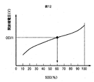
- FIG. 12 is a diagram illustrating the relationship between the open-circuit voltage of the high-voltage battery 420 and the SOC.
- the open circuit voltage (V) and SOC (%) of the high voltage battery 420 are in a relationship as shown in FIG. Therefore, if the open circuit voltage (V) of the high voltage battery 420 is known, the SOC (%) can be obtained. For example, when the open-circuit voltage value is OCV1 shown in FIG. 12, the SOC value is calculated to be 60%.
- the battery control device 410 calculates the open-circuit voltage of the high-voltage battery 420 from the detection value of the voltmeter 400V in FIG. 4 will be described.
- OCV Vdc ⁇ R1 ⁇ Idc ⁇ Vp (1)
- the open circuit voltage (OCV) of the high voltage battery 420 is obtained by the above equation 1.
- Vdc (V) is a detected value of the voltmeter 400V
- R1 ( ⁇ ) is an internal resistance value of the high voltage battery 420
- Idc (A) is a detected value of the ammeter 400A (in the case of discharging, the sign is minus, In the case of charging, the sign is plus)
- Vp (V) represents the polarization voltage value of the high voltage battery 420, respectively.
- the above internal resistance value R1 varies depending on the temperature and state of the high voltage battery 420.
- the battery cells 420 (1) to 420 (n) are provided with one or more thermistors (not shown) so that the temperature of each battery cell can be detected.
- the battery control device 410 can obtain the open-circuit voltage of the high-voltage battery 420 from Equation 1 with reference to the map data. Based on this result, the SOC value can be obtained from FIG.
- the battery control device 410 can obtain the SOC of the high-voltage battery 420 during charging / discharging from the following Equation 2.
- SOCn (%) kSOC (v) n + (1 ⁇ k) SOC (i) n Equation 2
- SOC (v) n represents the SOC value obtained from the OCV in Equation 1.
- SOC (i) n represents the SOC value obtained from the integrated value of the input / output current flowing through the high voltage battery 420, and is obtained by the following equation (3).
- SOC (i) n ( ⁇ Iddcdt) / Q (3)
- Idc (A) represents the detection value of the ammeter 400A (the sign is negative for discharging and the sign is positive for charging), and Q (Ah) is the high voltage battery 420, as in Expression 1.
- k is a variable. As the current input / output from the high voltage battery 420 is larger, k is smaller, and as the current is smaller, k is larger. That is, when the input / output current of the high-voltage battery 420 is large, SOC (i) n representing the integrated term of the input / output current is dominant in Equation 2, and conversely, when the input / output current is small, the voltage term is The represented SOC (v) n becomes dominant.
- Equation 2 in order to increase the SOC detection accuracy, the SOC value obtained from the open circuit voltage and the SOC value obtained from the integration of the input / output current values of the high-voltage battery 420 are expressed as k values. It is prorated by the calculation.
- the value of the battery capacity Q in Equation 3 varies depending on the life (degradation degree) of the high voltage battery 420 and the like. Therefore, the value of the battery capacity Q for various situations is acquired in advance, mapped, and stored in the battery control device 410.
- the battery control device 410 When performing the SOC detection error correction, the battery control device 410 sets the input / output current of the high voltage battery 420 to 0 and sets the integrated value of the input / output current so far to 0. Thereby, in the above equation 2, the value of SOC (i) n based on the integrated value of current is set to 0, and the value of SOC (v) n based on the open circuit voltage at that time is obtained as the value of initial SOC. In this way, the battery control device 410 can perform error correction with respect to the SOC of the high voltage battery 420.
- SOCn (%) kSOC (v) n + (1 ⁇ k) ⁇ SOC (i) n ⁇ 1 + (Idc ′ ⁇ dt) / Q ⁇
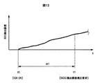
- FIG. 13 is a diagram showing a time change state of the SOC detection error after the IGN is turned ON.
- t0 represents the time of IGN ON. That is, time t0 is the timing when the driver turns on the start start switch (not shown) of the electric vehicle 1.
- the SOC detection error Normally, since the SOC detection error correction is performed at the time t0, the SOC detection error once becomes zero. Thereafter, the SOC detection error gradually increases as time elapses.
- the battery control device 410 transmits the SOC detection error correction request at the timing of time t1 when the predetermined time dt1 has elapsed from time t0, the SOC detection error correction is performed when the SOC detection error correction permission is subsequently received. As a result, the SOC detection error becomes zero.
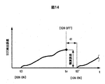
- FIG. 14 is a diagram showing a time change state of the SOC detection error when IGN ON, IGN OFF, and IGN ON are continuously performed.
- t0 is the time when IGN is turned on, that is, the timing when the driver turns on the travel start switch (not shown) of the electric vehicle 1 as in FIG. 13.
- the SOC detection error correction is normally performed at the time t0, so the SOC detection error once becomes zero. Thereafter, the SOC detection error gradually increases as time elapses.
- te represents the IGN OFF timing.
- the electric vehicle 1 stops according to the driver's intention. Thereafter, when the travel start switch (not shown) of the electric vehicle 1 is turned on again at the time t0 ′ after the time dt has elapsed from the time te, the electric vehicle 1 is turned on similarly to the time t0. Performs SOC detection error correction and starts running. After the electric vehicle 1 starts running, the SOC detection error gradually increases.
- Equation 1a From Equation 1a, it can be seen that if the voltage value of the high voltage battery 420 is detected from the voltmeter 400V as the value of Vdc, the value of OCV is obtained.
- the SOC detection error correction is performed by obtaining the initial SOCn (%) from FIG. 12 based on the OCV value. Thereafter, when the startup sequence of the battery control device 410 proceeds and the high voltage battery 420 is connected to the power conversion circuit 220 and current starts to flow, SOC detection is started based on Equation 2.
- Equation 1b it can be seen that if the voltage value of the high voltage battery 420 is detected as the value of Vdc from the voltmeter 400V, the OCV can be calculated from the mapped polarization voltage Vp value.
- the SOC detection error correction is performed by obtaining the initial SOCn (%) from FIG. 12 based on the OCV value.
- the initial SOC may be set to SOCn (%) when IGN is OFF.
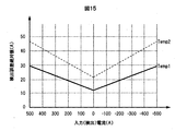
- FIG. 15 is a diagram illustrating an example of a detection error of the current sensor with respect to the input current.
- Temp1 represents an absolute value of a detection error with respect to an input (detection) current at a reference temperature (for example, 25 ° C.) in a general current sensor.
- the absolute value here is the case where an error in the positive direction (a value larger than the true value) occurs with respect to the input (detection) current, and an error in the negative direction (a value smaller than the true value).
- the reason why the input (detection) current has plus and minus is that the direction in which the high voltage battery 420 is discharged is defined as minus, and the current in the charging direction is defined as plus.
- the detection error of the current sensor varies within a range lower than Temp1 indicated by a solid line in FIG.
- Temp_U represents the upper limit of detection error of a general current sensor.
- the detection error of the current sensor increases as Temp_U.
- a general current sensor has a temperature characteristic.
- the ammeter 400A shown in FIG. That is, if the current sensor having an error is used as the ammeter 400A to detect the input / output current of the high voltage battery 420 and the SOC is detected based on the integrated value of the input / output current, the SOC detection error increases with time. I will do it. Note that in FIG. 15, even if the input (detection) current is zero, the absolute value of the detection error is not zero.
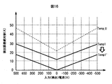
- FIG. 16 is a diagram illustrating an example of a detection error of the current sensor with respect to the input current after the SOC detection error correction.
- Temp1 represents the absolute value of the detection error with respect to the input (detection) current in the ammeter 400A after the SOC detection error correction.
- FIG. 16 shows that the value of Temp1 'is zero when the input (detection) current is zero. Therefore, if the input / output current from the high voltage battery 420 is known to be zero, the battery control device 410 can offset the detection value of the ammeter 400A from Temp1 to Temp1 'as shown in FIG. Thereby, when the actual input / output current of the high voltage battery 420 is zero, the detection value of the input current by the ammeter 400A can be corrected to be zero.
- the battery control device 410 can correct the SOC detection error.
- the battery control device 410 does not know when the input / output current of the high voltage battery 420 becomes zero. . Therefore, the SOC detection error correction cannot be performed until the IGN is turned on again after the IGN is turned off by the driver's intention.
- the battery control device 410 receives the SOC detection error correction permission signal transmitted from the power conversion control device 210, whereby the high voltage battery 420 and the power conversion circuit 220 are electrically connected. Even after being connected to, it is possible to know the timing when the input / output current of the high voltage battery 420 becomes zero. Therefore, it is possible to correct the detection error of the charged state of the high voltage battery 420 while the electric vehicle 1 is traveling without particularly increasing the cost.
Landscapes
- Engineering & Computer Science (AREA)
- Power Engineering (AREA)
- Life Sciences & Earth Sciences (AREA)
- Sustainable Development (AREA)
- Sustainable Energy (AREA)
- Transportation (AREA)
- Mechanical Engineering (AREA)
- General Physics & Mathematics (AREA)
- Physics & Mathematics (AREA)
- Manufacturing & Machinery (AREA)
- Chemical & Material Sciences (AREA)
- Chemical Kinetics & Catalysis (AREA)
- Electrochemistry (AREA)
- General Chemical & Material Sciences (AREA)
- Electric Propulsion And Braking For Vehicles (AREA)
- Charge And Discharge Circuits For Batteries Or The Like (AREA)
- Secondary Cells (AREA)
Abstract
コストアップなしで、車両の走行中に電池の充電状態の検出誤差を補正する。 電力変換制御装置210は、高電圧バッテリ420の充放電を制御するバッテリ制御装置410と接続され、高電圧バッテリ420から供給される直流電流を用いて回転電機30に交流電流を供給する電力変換回路220を制御する。電力変換制御装置210は、高電圧バッテリ420から供給される直流電流の電流値が0または0に向かっているときに、バッテリ制御装置410により検出された高電圧バッテリ420の充電状態に対する誤差補正の開始を許可するためのSOC検出誤差補正許可信号を、バッテリ制御装置410に送信する。
Description
本発明は、電力変換制御装置およびバッテリ制御装置と、これらを備えた駆動制御サブシステムに関する。
従来、AGV(Automatic Guided Vehicle)において、負荷(モータ)、インバータ、コンバータ、受電部、主電源、副電源および電源間切り替えスイッチを備えた電池システムが知られている(特許文献1)。この電池システムは、負荷の駆動時間が所定の補正開
始時間に達すると、予め設定された電流値の検査電流で主電源を充放電したときの端子間電圧を測定し、その測定値に基づいて、電流積算で求められた電池の充電状態(SOC: State Of Charge)の誤差を補正する。
始時間に達すると、予め設定された電流値の検査電流で主電源を充放電したときの端子間電圧を測定し、その測定値に基づいて、電流積算で求められた電池の充電状態(SOC: State Of Charge)の誤差を補正する。
特許文献1の電池システムでは、検査電流で主電源を充放電したときでも負荷への電力供給状態を維持するために、副電源が必要であり、さらに主電源と副電源を切り替えるための切り替えスイッチも必要である。そのため、システム構成が複雑化してコストアップするという問題がある。
本発明による電力変換制御装置は、バッテリの充放電を制御するバッテリ制御装置と接続され、前記バッテリから供給される直流電流を用いてモータに交流電流を供給する電力変換回路を制御するものであって、前記直流電流の電流値が0または0に向かっているときに、前記バッテリ制御装置により検出された前記バッテリの充電状態に対する誤差補正の開始を許可するための許可信号を、前記バッテリ制御装置に送信する。本発明によるバッテリ制御装置は、電力変換回路からモータに供給される交流電流を生成するための直流電流を前記電力変換回路に供給するバッテリの充放電を制御するものであって、前記バッテリの充電状態を検出し、前記直流電流の電流値が0または0に向かっているときに、前記バッテリの充電状態に対する誤差補正を行う。本発明による駆動制御サブシステムは、上記の電力変換制御装置とバッテリ制御装置とを備える。
本発明によれば、コストアップなしで、車両の走行中に電池の充電状態の検出誤差を補正することができる。
以下では、本発明の一実施形態に係る電力変換制御装置、バッテリ制御装置および駆動制御サブシステムについて説明する。図1は、本発明の一実施形態に係る電力変換制御装置及びバッテリ制御装置を搭載した電動車両1の構成を示す図である。なお、電動車両1は一般的な構成の電動車両の例である。本実施形態では電動車両1が前輪駆動の例を示すが、後輪駆動または四輪駆動車でも構わない。
回転電機30は、ギヤボックス40を経由して車軸40R、40Lと機械的に接続されている。車軸40R、40Lは、駆動輪(前輪)10FR、10RLにそれぞれ接続されている。駆動輪10FR、10RLは、ギヤボックス40及び車軸40R、40Lを経由した回転電機30の出力を駆動力として地面に伝えることで、電動車両を駆動する。従動輪(後輪)10RR、10RLは、車軸70L、70Rによりディファレンシャルギヤ60にそれぞれ接続されている。
ビークルコントローラ(VCM)100は、電動車両1を統合的に制御するコントローラである。ビークルコントローラ100は、CAN通信のBUSライン110により、電力変換制御装置(MCU)210、バッテリ制御装置(BCU)410、充電器制御装置510およびコンバータ制御装置610と接続されている。この接続により、ビークルコントローラ100、電力変換制御装置210、バッテリ制御装置410、充電器制御装置510およびコンバータ制御装置610の間で、互いにCANメッセージの送受信か可能となっている。
電力変換制御装置210は、電力変換回路220と接続されている。電力変換回路220は、3相ハーネス9U、9V、9Wにより回転電機30と接続されており、これらを介して回転電機30との間で交流電力をやり取りできるようになっている。また電力変換回路220は、DCハーネス9P、9Nにより高電圧バッテリ420と接続されており、このDCハーネス9P、9Nを介して、高電圧バッテリ420との間で直流電力をやり取りできるようになっている。
DCハーネス9Pは、正極リレー9PS、プリチャージ抵抗9PPR及びプリチャージリレー9PPSを備えている。プリチャージ抵抗9PPRとプリチャージリレー9PPSは直列に接続されており、これらは正極リレー9PSと並列に取り付けられている。DCハーネス9Pは、正極リレー9PS及びプリチャージリレー9PPSの接続状態を切り替えることで、高電圧バッテリ420から供給される直流電力の接続及び切断を随時出来るようになっている。DCハーネス9Nは、負極リレー9NSを備えている。DCハーネス9Nは、負極リレー9NSの接続状態を切り替えることで、高電圧バッテリ420から供給される直流電力の接続及び切断を随時出来るようになっている。
バッテリ制御装置410は、高電圧バッテリ420と接続されている。高電圧バッテリ420は、ハーネス9P1、9N1により充電器500と接続されており、これらを介して充電器500との間で直流電力のやり取りが出来るようになっている。
充電器制御装置510は、充電器500と接続されている。充電器500には、外部電源である充電スタンド800と接続するためのハーネス9P3、9N3と接続されている。充電器500と充電スタンド800とがハーネス9P3、9N3を介して互いに接続された状態で、充電器制御装置510が充電スタンド800からの電力を制御することで、高電圧バッテリ420が充電される。尚、本実施形態では充電の場合を説明するが、充電器500が給電機能を備える場合には、高電圧バッテリ420の電力を外部に供給することも可能である。
コンバータ制御装置610は、DCDCコンバータ600と接続されている。DCDCコンバータ600は、上記のハーネス9P1、9N1にそれぞれ接続されたハーネス9P2、9N2により高電圧バッテリ420と接続されている。これにより、高電圧バッテリ420から供給される直流電力をDCDCコンバータ600で適宜電圧変換して低電圧バッテリ700に出力できるようになっている。
低電圧バッテリ700は、例えば12~24V程度の出力電圧を有する。低電圧バッテリ700はDCDCコンバータ600と接続されており、適宜DCDCコンバータ600からの直流電力により充電されている。
図2は、本発明の一実施形態に係る車両駆動システムの構成を示す図である。図2の車両駆動システムは、図1の回転電機30、ビークルコントローラ100、充電器500、充電器制御装置510、DCDCコンバータ600、コンバータ制御装置610及び低電圧バッテリ700と、電力変換装置200及びバッテリ装置400とを有する。電力変換装置200は、図1の電力変換制御装置210及び電力変換回路220と、平滑コンデンサ200C及び電流センサ20Cとによって構成される。バッテリ装置400は、図1のバッテリ制御装置410、高電圧バッテリ420及びDCハーネス9P、9Nによって構成される。なお、電力変換制御装置210及びバッテリ制御装置410を合わせて、駆動制御サブシステムと呼ぶこともある。
ドライバーが電動車両1の走行開始スイッチをON(以下IGN ON)すると、ビークルコントローラ100がCAN通信のBUSライン110に起動指令を送信する。電力変換制御装置210及びバッテリ制御装置410は、ビークルコントローラ100から送信された起動指令をBUSライン110から受信すると、所定の起動シーケンスをそれぞれ開始する。
バッテリ制御装置410が起動シーケンスを開始すると、後述するSOC検出誤差補正及び初期SOC値検出が行われる。続いて、負極リレー9NSがON(接続)され、その次にプリチャージリレー9PPSがON(接続)される。これにより、高電圧バッテリ420と電力変換回路220との導通が開始され、プリチャージ抵抗9PPRを通って充電電流が平滑コンデンサ200Cに流れる。その後、平滑コンデンサ200Cの両端電圧がある一定値以上になると、正極リレー9PSがON(接続)され、プリチャージリレー9PPSがOFF(切断)される。この動作は、平滑コンデンサ200Cに過大な突入電流が流れるのを防ぐためである。
ドライバーが電動車両1の走行開始スイッチをOFF(以下IGN OFF)すると、ビークルコントローラ100がCAN通信のBUSライン110に終了指令を送信する。電力変換制御装置210及びバッテリ制御装置410は、ビークルコントローラ100から送信された終了指令をBUSライン110から受信すると、所定の終了シーケンスをそれぞれ開始する。バッテリ制御装置410が終了シーケンスを開始すると、負極リレー9NSと正極リレー9PSがそれぞれOFF(切断)され、高電圧バッテリ420は電力変換回路220から切り離される。
図3は、回転電機30及び電力変換装置200の詳細を示す図である。
電力変換回路220は、電力変換制御装置210の制御により、高電圧バッテリ420から供給される直流電流(直流電力)を交流電流(交流電力)に変換して回転電機30に供給する。また、電力変換回路220は、回転電機30の回転によって生じた交流電力を直流電力に変換することで、高電圧バッテリ420を充電することもできる。
電力変換回路220は、U相、V相、W相にそれぞれ対応する3相の上アームスイッチング素子20UU、20VU、20WUと、U相、V相、W相にそれぞれ対応する3相の下アームスイッチング素子20UL、20VL、20WLとを有する。これらのスイッチング素子は、例えばIGBTやMOSFETなどで構成される。
電力変換回路220と回転電機30の間には、ハーネス9U、9V、9Wが設けられている。ハーネス9Uは、回転電機30のU相コイル30Uと電力変換回路220のU相接続端子20Uとの間を電気的に接続している。U相接続端子20Uは、U相上アームスイッチング素子20UUとU相下アームスイッチング素子20ULの間に設けられている。ハーネス9Vは、回転電機30のV相コイル30Vと電力変換回路220のV相接続端子20Vとの間を電気的に接続している。V相接続端子20Vは、V相上アームスイッチング素子20VUとV相下アームスイッチング素子20VLの間に設けられている。ハーネス9Wは、回転電機30のW相コイル30Wと電力変換回路220のW相接続端子20Wとの間を電気的に接続している。W相接続端子20Wは、W相上アームスイッチング素子20WUとW相下アームスイッチング素子20WLの間に設けられている。
回転電機30は、ハーネス9U、9V、9Wを介して電力変換回路220から入力された交流電力を用いてロータ(不図示)を回転駆動させることで、電気出力を機械出力に変換する(力行)。また、回転電機30に外部から機械入力が与えられることでロータが回されると、回転電機30は発電機として作用し、電気出力が可能となる(回生)。
磁極位置センサ30Rは、回転電機30のロータ磁極位置を検出する。磁極位置センサ30Rによって検出されたロータ磁極位置の情報は、電力変換制御装置210に出力される。サーミスタ30Tは、回転電機30のコイル温度を検出する。サーミスタ30Tによって検出されたコイル温度の情報は、電力変換制御装置210に出力される。電流センサ20Cは、ハーネス9U、9V、9Wに取り付けられており、電力変換回路220と回転電機30の間に流れる電流値を検出する。電流センサ20Cによって検出された各相の電流の情報は、電力変換制御装置210に出力される。
回転電機30が力行する場合は、電力変換制御装置210の制御により、ロータの磁極位置に応じて、電力変換回路220の6つのスイッチング素子20UU、20UL、20VU、20VL、20WU、20WLがそれぞれスイッチング動作を行う。これにより、必要な位相及び振幅の3相交流電力を、回転電機30のU相コイル30U、V相コイル30V、W相コイル30Wにそれぞれ流す。すると回転電機30は、入力された交流電力を機械出力に変換して出力する。このとき電力変換制御装置210は、実際に回転電機30に流れる電流の検出結果に基づくフィードバック制御を行うことで、目標の電流値による交流電流が回転電機30に安定して流れるように制御する。
なお、電力変換制御装置210は、サーミスタ30Tにより検出された回転電機30のコイル温度を監視し、その監視結果に基づく制御を行うこともできる。例えば、コイル温度がある閾値を越えたときには、回転電機30の焼損を防止するために、回転電機30に入力される交流電力を所定値以下に制限する。
図4は、バッテリ装置400の詳細を示す図である。
高電圧バッテリ420は、DCハーネス9P、9Nを経由して、電力変換装置200に直流電力を出力したり、電力変換装置200から直流電力を入力したりする。本実施形態では、バッテリ装置400内に正極リレー9PS、負極リレー9NS、プリチャージリレー9PPS及びプリチャージ抵抗9PPRを格納した例を示したが、高電圧バッテリ420の外にこれらが配置される場合もある。ハーネス9P1、9N2は高電圧バッテリ420と充電器500及びDCDCコンバータ600を電気的に接続している。
高電圧バッテリ420は、n個のバッテリセル420(1)~420(n)により構成される。nは1以上の任意の整数である。なお、本実施形態の高電圧バッテリ420では、バッテリセル420(1)~420(n)の全てを直列に接続してもよいし、並列に接続してもよい。また、直列と並列の組み合わせとしてもよい。高電圧バッテリ420には、1個または複数個の温度センサ(図示せず)が取り付けており、この温度センサで検出されたバッテリ温度の情報がバッテリ制御装置410に入力される。
電圧計400Vは、高電圧バッテリ420の総電圧を測定する。電圧計400Vは、各バッテリセル420(1)~420(n)の電圧を検出して加算することで高電圧バッテリ420の総電圧を測定してもよいし、単純にバッテリセル420(1)の正極と420(n)の負極間の電圧を測定することで高電圧バッテリ420の総電圧を測定してもよい。電流計400Aは、高電圧バッテリ420に入出力される電流を測定する。電圧計400Vで検出された高電圧バッテリ420の総電圧の情報及び電流計400Aで検出された高電圧バッテリ420の電流の情報は、バッテリ制御装置410に入力される。
図5は、ビークルコントローラ100、バッテリ制御装置410及び電力変換制御装置210の間で送受信される従来のCANメッセージの一例を示す図である。図5において、各送受信メッセージには識別のためのIDが割り振られている。
例えば、ビークルコントローラ100は、ある任意の時間間隔で、送信メッセージリストにある目標トルク(ID:010)のメッセージをCAN通信のBUSライン110に送信する。電力変換制御装置210のメッセージ受信リストには、目標トルク(ID:010)があるため、電力変換制御装置210は、この目標トルクのメッセージを受信する。そして、受信したメッセージで示された目標トルクの値に基づいて、回転電機30のトルクを制御する。
また、例えば、バッテリ制御装置410は、ある任意の時間間隔で、送信メッセージリストにあるバッテリ状態(ID:040)のメッセージをCAN通信のBUSライン110に送信する。ビークルコントローラ100のメッセージ受信リストには、バッテリ状態(ID:040)があるため、ビークルコントローラ100は、このバッテリ状態のメッセージを受信して、電動車両1の制御に活用する。なお、バッテリ状態(ID:400)のメッセージには、例えば、バッテリ電力(充電・放電)の情報、バッテリ総電圧の情報、バッテリ電流の情報、バッテリSOCの情報、バッテリ温度の情報などが含まれる。
図6は、ビークルコントローラ100、バッテリ制御装置410及び電力変換制御装置210における従来のCANメッセージ送受信の一例を示す図である。図5で説明した上記のCANメッセージの送受信における実際の信号の流れを、図6を参照して以下に説明する。
ビークルコントローラ100からは、図5に示した目標トルク(ID:010)のメッセージが、矢印110ASのように出力される。この目標トルクのメッセージは、CAN通信のBUSライン110上を流れて、矢印110ARのように電力変換制御装置210に入力される。
また、バッテリ制御装置410からは、図5に示したバッテリ状態(ID:040)のメッセージが、矢印410ASのように出力される。このバッテリ状態のメッセージは、CAN通信のBUSライン110上を流れて、矢印410ARのようにビークルコントローラ100に入力される。
図7は、ビークルコントローラ100、バッテリ制御装置410及び電力変換制御装置210の間で送受信されるSOC検出誤差補正要求信号のCANメッセージの一例を示す図である。
電動車両1がIGN ONされると、前述のように高電圧バッテリ420と電力変換回路220との導通が開始され、電力変換制御装置210及びバッテリ制御装置410において所定の起動シーケンスが開始される。IGN ONから所定時間が経過すると、バッテリ制御装置410は、送信メッセージリストにあるSOC検出誤差補正要求(ID:042)のメッセージをCAN通信のBUSライン110に送信する。ビークルコントローラ100のメッセージ受信リスト及び電力変換制御装置210のメッセージ受信リストには、SOC検出誤差補正要求(ID:042)があるため、ビークルコントローラ100及び電力変換制御装置210は、このSOC検出誤差補正要求のメッセージをそれぞれ受信する。これにより、ビークルコントローラ100及び電力変換制御装置210は、バッテリ制御装置410がSOC検出誤差の補正を要求していることをそれぞれ知ることが出来る。
図8は、ビークルコントローラ100、バッテリ制御装置410及び電力変換制御装置210におけるSOC検出誤差補正要求信号のCANメッセージ送受信の一例を示す図である。図7で説明した上記のCANメッセージの送受信における実際の信号の流れを、図8を参照して以下に説明する。
バッテリ制御装置410からは、図7に示したSOC検出誤差補正要求(ID:042)のメッセージが、矢印410BSのように出力される。このSOC検出誤差補正要求のメッセージは、CAN通信のBUSライン110上を流れて、矢印410BR1、410BR2のように電力変換制御装置210及びビークルコントローラ100にそれぞれ入力される。
以上説明したように、バッテリ制御装置410は、高電圧バッテリ420と電力変換回路220との導通が開始されてから所定時間経過後に、高電圧バッテリ420のSOCに対する誤差補正の開始の許可を要求するための要求信号として、SOC検出誤差補正要求のメッセージを送信する。このSOC検出誤差補正要求のメッセージは、電力変換制御装置210及びビークルコントローラ100において受信される。
図9は、ビークルコントローラ100、バッテリ制御装置410、電力変換制御装置210及びコンバータ制御装置610の間で送受信されるSOC検出誤差補正許可信号のCANメッセージの一例を示す図である。
電力変換制御装置210は、高電圧バッテリ420から電力変換回路220に供給される直流電流の電流値が0または0に向かっていると判断すると、送信メッセージリストにあるSOC検出誤差補正許可(ID:090)のメッセージをCAN通信のBUSライン110に送信する。バッテリ制御装置410のメッセージ受信リスト及びコンバータ制御装置610のメッセージ受信リストには、SOC検出誤差補正許可(ID:090)があるため、バッテリ制御装置410及びコンバータ制御装置610は、このSOC検出誤差補正許可のメッセージをそれぞれ受信する。これにより、バッテリ制御装置410及びコンバータ制御装置610は、SOCの検出誤差の補正が許可されたことをそれぞれ知り、後述するようなSOC検出誤差の補正動作をそれぞれ開始することが出来る。
具体的には、電力変換制御装置210は、電力変換回路220の制御状態が、高電圧バッテリ420からの直流電流の電流値を0にするための所定の制御状態(ゼロ電流制御状態)であるか否かを判断することで、直流電流の電流値が0または0に向かっているか否かを判断することができる。このゼロ電流制御状態には、例えば三相短絡の制御状態が含まれる。三相短絡とは、電力変換回路220の三相の上アームスイッチング素子20UU、20VU、20WUの全て、または三相の下アームスイッチング素子20UL、20VL、20WLの全てが同時にONした状態のことである。この三相短絡の制御状態では、電力変換回路220と回転電機30の間で電流が還流する。そのため、高電圧バッテリ420と電力変換回路220の間では、入出力電流はゼロである。
また、上記のゼロ電流制御状態には、例えばスイッチング停止の制御状態が含まれる。スイッチング停止とは、電力変換回路220の三相の上下アームのスイッチング素子20UU、20VU、20WU、20UL、20VL、20WLの全てがスイッチング動作を停止している状態のことである。このスイッチング停止の制御状態では、電力変換回路220と回転電機30の間の電流が遮断される。そのため、高電圧バッテリ420と電力変換回路220の間では、入出力電流はゼロである。
なお、スイッチング停止状態であっても、回転電機30の回転数がある一定値以上になると、回転電機30が発生する誘起電圧が所定のダイオード導通電圧以上となる。このとき、電力変換装置200の6つのスイッチング素子20UU、20VU、20WU、20UL、20VL、20WLにあるダイオード部分を通って、電力変換回路220から高電圧バッテリ420側に直流電流が流れることで、高電圧バッテリ420が充電される。そのため、こうした状態のときには、電力変換制御装置210からSOC検出誤差補正許可のメッセージを送信しないことが好ましい。具体的には、スイッチング停止状態で回転電機30がある一定値以上になるような使い方が想定される場合は、スイッチング停止状態であり、かつ回転電機30の回転数がある一定値以下(すなわち誘起電圧が所定値以下)であるときに、電力変換制御装置210がSOC検出誤差補正許可のメッセージを送信するようにすれば良い。
なお、上記では、電力変換制御装置210が三相短絡やスイッチング停止の制御状態を判断することで、ゼロ電流制御状態を判断してSOC検出誤差補正許可のメッセージを送信する例を説明した。しかし、ビークルコントローラ100が送信リストにある三相短絡(ID:015)またはSW停止(ID:020)のメッセージを送信し、これらのメッセージを電力変換制御装置210が受信することで、電力変換制御装置210がSOC検出誤差補正許可のメッセージを送信するトリガとしても良い。
コンバータ制御装置610は、SOC検出誤差補正許可のメッセージを受信したら、DCDCコンバータ600の動作を停止させる。これにより、SOC検出誤差補正の動作中に、DCDCコンバータ600を介して高電圧バッテリ420から低電圧バッテリ700が充電されないようにする。あるいは、DCDCコンバータ600の電圧変換時に高電圧バッテリ420からハーネス9P1、9N1を通って流れる電流値がある一定値より大きい場合には、SOC検出誤差補正の動作中に、DCDCコンバータ600の動作を停止するようにしてもよい。
図10は、ビークルコントローラ100、バッテリ制御装置410、電力変換制御装置210及びコンバータ制御装置610におけるSOC検出誤差補正許可信号のCANメッセージ送受信の一例を示す図である。図9で説明した上記のCANメッセージの送受信における実際の信号の流れを、図10を参照して以下に説明する。
電力変換制御装置210からは、図9に示したSOC検出誤差補正許可(ID:090)のメッセージが、矢印210BSのように出力される。このSOC検出誤差補正許可のメッセージは、CAN通信のBUSライン110上を流れて、矢印210BR1、210BR2のようにバッテリ制御装置410及びコンバータ制御装置610にそれぞれ入力される。
以上説明したように、電力変換制御装置210は、高電圧バッテリ420から電力変換回路220に供給される直流電流の電流値が0または0に向かっているときに、高電圧バッテリ420のSOCに対する誤差補正の開始を許可するための許可信号として、SOC検出誤差補正許可のメッセージを送信する。このSOC検出誤差補正許可のメッセージは、バッテリ制御装置410及びコンバータ制御装置610において受信される。
なお、上記で図5~図10を参照して説明したように、CAN通信のBUSライン110には、ビークルコントローラ100、電力変換制御装置210、バッテリ制御装置410、充電器制御装置510及びコンバータ制御装置610から送信されたさまざまな信号が流れされている。そのため、BUSライン110に流れる信号量が過大となった場合には、本発明に係るSOC検出誤差補正要求(ID:042)やSOC検出誤差補正許可(ID:090)のメッセージの送受信を円滑に行えないという問題が発生する。そこで、これらのメッセージを送受信するための通信ラインをBUSライン110とは別に設けるようにしてもよい。
図11は、CAN通信のBUSライン110に加えてローカルCAN通信ライン120を設けた車両駆動システムの構成を示す図である。図11に示すローカルCAN通信ライン120は、上記のような問題を鑑みて追加されたものである。すなわち、図11の車両駆動システムでは、電力変換制御装置210、バッテリ制御装置410、充電器制御装置510、コンバータ制御装置610間の信号の送受信を円滑に行うために、ローカルCAN通信ライン120が設けられている。このようにすることで、本発明のSOC検出誤差補正要求(ID:042)やSOC検出誤差補正許可(ID:090)の送受信を、必要なときに行えるという効果がある。
以上説明したように、図11の車両駆動システムの構成では、電力変換制御装置210、バッテリ制御装置410、充電器制御装置510及びコンバータ制御装置610が、CAN通信のBUSライン110とは異なるローカルCAN通信ライン120を介して互いに接続されている。バッテリ制御装置410から電力変換制御装置210やビークルコントローラ100へのSOC検出誤差補正要求のメッセージや、電力変換制御装置210からバッテリ制御装置410やコンバータ制御装置610へのSOC検出誤差補正許可のメッセージは、このローカルCAN通信ライン120を介して送信される。
次に、バッテリ制御装置410が行うSOC検出誤差補正について説明する。図12は、高電圧バッテリ420の開放端電圧とSOCの関係を示す図である。高電圧バッテリ420の開放端電圧(V)とSOC(%)は、図12に示すような関係にある。したがって、高電圧バッテリ420の開放端電圧(V)が分かれば、SOC(%)を求めることができる。例えば、開放端電圧の値が図12に示すOCV1であるとき、SOCの値は60%と求められる。
ここで、図4の電圧計400Vの検出値から、バッテリ制御装置410が高電圧バッテリ420の開放端電圧を計算する方法を述べる。
OCV=Vdc-R1・Idc-Vp ・・・・式1
高電圧バッテリ420の開放端電圧(OCV)は上記式1で求められる。式1において、Vdc(V)は電圧計400Vの検出値、R1(Ω)は高電圧バッテリ420の内部抵抗値、Idc(A)は電流計400Aの検出値(放電の場合は符号がマイナス、充電の場合は符号がプラス)、Vp(V)は高電圧バッテリ420の分極電圧値をそれぞれ表す。
高電圧バッテリ420の開放端電圧(OCV)は上記式1で求められる。式1において、Vdc(V)は電圧計400Vの検出値、R1(Ω)は高電圧バッテリ420の内部抵抗値、Idc(A)は電流計400Aの検出値(放電の場合は符号がマイナス、充電の場合は符号がプラス)、Vp(V)は高電圧バッテリ420の分極電圧値をそれぞれ表す。
上記の内部抵抗値R1は、高電圧バッテリ420の温度や状態によって変化する。分極電圧値Vpも、高電圧バッテリ420の温度や状態によって変化する。また、分極電圧値Vpは、Idc=0となってもすぐにゼロにならず、時間と共に減衰してゼロとなる。このため、様々な温度に対する内部抵抗値R1や分極電圧値Vpのデータが予め取得されており、マップ化されてバッテリ制御装置410内に記憶されている。また、バッテリセル420(1)~420(n)には、1個以上のサーミスタ(図示せず)が設けられており、各バッテリセルの温度を検出できるようになっている。そのため、電圧計400Vの検出値Vdcと電流計400Aの検出値Idcが分かれば、バッテリ制御装置410はマップデータを参照して、式1から高電圧バッテリ420の開放端電圧を求めることができる。この結果を基に、図12からSOC値を求めることができる。
バッテリ制御装置410は、充放電中の高電圧バッテリ420のSOCを以下の式2から求めることができる。
SOCn(%)=kSOC(v)n+(1-k)SOC(i)n ・・・・式2
SOCn(%)=kSOC(v)n+(1-k)SOC(i)n ・・・・式2
式2において、SOC(v)nは、式1のOCVから求められるSOCの値を表す。一方、SOC(i)nは、高電圧バッテリ420に流れる入出力電流の積算値から求められるSOCの値を表し、以下の式(3)で求められる。
SOC(i)n=(∫Idcdt)/Q ・・・・式3
SOC(i)n=(∫Idcdt)/Q ・・・・式3
式3において、Idc(A)は式1と同様に、電流計400Aの検出値(放電の場合は符号がマイナス、充電の場合は符号がプラス)を表し、Q(Ah)は高電圧バッテリ420のバッテリ容量を表す。また、kは変数であり、高電圧バッテリ420から入出力する電流が大きいほどkが小さくなり、電流が小さいほどkが大きくなる。つまり、高電圧バッテリ420の入出力電流が大きい時は、式2において入出力電流の積算項を表すSOC(i)nが支配的であり、反対に入出力電流が小さい時は、電圧項を表すSOC(v)nが支配的となる。このように式2では、SOCの検出精度を上げるために、開放端電圧から求められるSOCの値と、高電圧バッテリ420の入出力電流値の積算から求められるSOCの値とを、kの値により按分して計算している。
式3のバッテリ容量Qの値は、高電圧バッテリ420の寿命(劣化度)等により変化する。そのため、様々な状況に対するバッテリ容量Qの値が予め取得されており、マップ化されてバッテリ制御装置410内に記憶されている。
バッテリ制御装置410は、SOC検出誤差補正を行う際には、高電圧バッテリ420の入出力電流を0にすると共に、それまでの入出力電流の積算値を0とする。これにより、上記の式2において、電流の積算値に基づくSOC(i)nの値を0として、そのときの開放端電圧に基づくSOC(v)nの値を初期SOCの値として求める。このようにして、バッテリ制御装置410は、高電圧バッテリ420のSOCに対する誤差補正を行うことができる。
なお、式2に関しては、高電圧バッテリ420のSOCの算出方法に対する一般的な考え方を示したに過ぎず、他の算出方法を用いてもよい。たとえば、式2の第二項を変化させた以下の式4を用いて、dt時間の差分を順次足し合わせていくやり方で高電圧バッテリ420のSOCを算出しても構わない。
SOCn(%)=kSOC(v)n+(1-k){SOC(i)n-1+(Idc’・dt)/Q} ・・・・式4
SOCn(%)=kSOC(v)n+(1-k){SOC(i)n-1+(Idc’・dt)/Q} ・・・・式4
図13は、IGN ON後のSOC検出誤差の時間変化の様子を示す図である。図13において、t0はIGN ONの時刻を表す。すなわち、時刻t0はドライバーが電動車両1の始動開始スイッチ(図示しない)をONしたタイミングである。通常は時刻t0のタイミングでSOC検出誤差補正が行われるため、一旦SOC検出誤差は0となる。その後、時間の経過に応じて徐々にSOC検出誤差は増加する。時刻t0から一定時間dt1経過した時の時刻t1のタイミングで、バッテリ制御装置410がSOC検出誤差補正要求を送信すると、その後にSOC検出誤差補正許可を受信したときに、SOC検出誤差補正が行われてSOC検出誤差が0となる。
図14は、IGN ON、IGN OFF、IGN ONが続けて行われた場合のSOC検出誤差の時間変化の様子を示す図である。図14において、t0は図13と同様に、IGN ONの時刻、すなわちドライバーが電動車両1の走行開始スイッチ(図示しない)をONしたタイミングである。この場合も図13と同様に、通常は時刻t0のタイミングでSOC検出誤差補正が行われるため、一旦SOC検出誤差は0となる。その後、時間の経過に応じて徐々にSOC検出誤差は増加する。
図14において、teはIGN OFFのタイミングを表す。この時刻teでは、ドライバーの意思によって電動車両1が停止する。その後、時刻teから時間dtが経過した後の時刻t0’において、ドライバーの意思により電動車両1の走行開始スイッチ(図示しない)が再びONされると、時刻t0のときと同様に、電動車両1はSOC検出誤差補正を行い、走行を開始する。電動車両1が走行を開始した後は、徐々にSOC検出誤差が増加する。
ここで、時刻t0の時点では、その前にドライバーが電動車両1の走行開始スイッチをOFF(IGN OFF)してから十分に時間が経過しており、高電圧バッテリ420は分極電圧Vpが十分に減衰してゼロとなった状態にあるとする。この状態でドライバーが電動車両1の走行開始スイッチをON(IGN ON)すると、バッテリ制御装置410が起動シーケンスを開始し、時刻t0時点での初期SOCが検出される。
時刻t0の時点では、高電圧バッテリ420の入出力電流の積算値はゼロであるため、式3の値が0となる。そのため、式2の第二項の値も0となり、式2は以下の式2aのように表される。
SOCn(%)=SOC(v)n ・・・・式2a
SOCn(%)=SOC(v)n ・・・・式2a
ここで、時刻t0では式1においてIdc=0、Vp=0なので、式1は以下の式1aのように表される。
OCV=Vdc ・・・・式1a
OCV=Vdc ・・・・式1a
式1aにより、電圧計400Vから高電圧バッテリ420の電圧値をVdcの値として検出すれば、OCVの値が求められることが分かる。このOCVの値により、図12から初期SOCn(%)が求められることで、SOC検出誤差補正が行われる。その後、バッテリ制御装置410の起動シーケンスが進み、高電圧バッテリ420が電力変換回路220に接続されて電流が流れ始めると、式2に基づいてSOC検出が開始される。
また、時刻teの時点でドライバーが電動車両1の走行開始スイッチをOFF(IGN OFF)してから時間dtを経過した後に、時刻t0’で再び走行開始スイッチをON(IGN ON)した場合に、時間dtがある閾値以上ならば、分極電圧Vpが十分に減衰してゼロとなったと考えられる。この場合、前述の時刻t0の場合と同様に初期SOCを検出する。
時間dtがある閾値以下ならば、分極電圧Vpを考慮して、式1は以下の式1bのように表される。
OCV=Vdc-Vp ・・・・式1b
OCV=Vdc-Vp ・・・・式1b
式1bにより、電圧計400Vから高電圧バッテリ420の電圧値をVdcの値として検出すれば、マップ化された分極電圧Vpの値からOCVを計算できることが分かる。このOCVの値により、図12から初期SOCn(%)が求められることで、SOC検出誤差補正が行われる。または、IGN OFF時のSOCn(%)に初期SOCを設定したりしても構わない。
図15は、入力電流に対する電流センサの検出誤差の一例を示す図である。図15において、Temp1は、一般的な電流センサにおける基準温度(例えば25℃)での入力(検出)電流に対する検出誤差の絶対値を表す。なお、ここで絶対値としているのは、入力(検出)電流に対して、プラス方向の誤差(真値より大きな値となる)が生じる場合と、マイナス方向の誤差(真値より小さな値となる)が生じる場合とがあるからである。また、入力(検出)電流にプラスとマイナスがあるのは、高電圧バッテリ420が放電する方向をマイナス、充電する方向の電流をプラスと定義しているからである。一般的に、図15で実線により示したTemp1よりも下の範囲内で、電流センサの検出誤差がばらつくことになる。
また、図15において、Temp_Uは、一般的な電流センサの検出誤差の上限を表す。例えば電流センサの温度が基準温度(25℃)から125℃に変化すると、電流センサの検出誤差はTemp_Uのように拡大する。このように、一般的な電流センサは温度特性を持っている。図4に示した電流計400Aも同様である。すなわち、誤差を持つ電流センサを電流計400Aとして使って高電圧バッテリ420の入出力電流を検出し、その入出力電流の積算値に基づいてSOC検出を行うと、時間経過と共にSOC検出誤差が拡大していく。なお、図15で注目すべき点は、入力(検出)電流がゼロであっても、検出誤差の絶対値がゼロではないことである。
図16は、SOC検出誤差補正後の入力電流に対する電流センサの検出誤差の一例を示す図である。図16において、Temp1’は、SOC検出誤差補正後の電流計400Aにおける入力(検出)電流に対する検出誤差の絶対値を表す。図16から、入力(検出)電流がゼロであるときに、Temp1’の値はゼロとなることが分かる。したがって、高電圧バッテリ420からの入出力電流がゼロであることが分かれば、バッテリ制御装置410は、図16に示すように電流計400Aの検出値をTemp1からTemp1’へオフセットすることができる。これにより、高電圧バッテリ420の実際の入出力電流がゼロであるときには、電流計400Aによる入力電流の検出値もゼロとなるように補正することができる。
ドライバーが電動車両1の走行開始スイッチをON(IGN ON)すると、DCハーネス9P、9Nにある負極リレー9NSとプリチャージリレー9PPSがON(接続)されることで、高電圧バッテリ420と電力変換回路220が電気的に接続される。この接続の前であれば、高電圧バッテリ420の入出力電流がゼロであるため、バッテリ制御装置410においてSOC検出誤差補正が可能である。
従来の車両駆動システムでは、上記のように高電圧バッテリ420と電力変換回路220が電気的に接続された後、バッテリ制御装置410は高電圧バッテリ420の入出力電流がゼロになるタイミングが分からない。そのため、ドライバーの意思によるIGN OFF後に再度IGN ONされるまで、SOC検出誤差補正を行うことができない。
一方、本実施形態の車両駆動システムでは、バッテリ制御装置410は、電力変換制御装置210から送信されるSOC検出誤差補正許可信号を受信することで、高電圧バッテリ420と電力変換回路220が電気的に接続された後でも、高電圧バッテリ420の入出力電流がゼロになるタイミングを知ることができる。そのため、特にコストアップすることなく、電動車両1の走行中に高電圧バッテリ420の充電状態の検出誤差を補正することができる。
以上説明した実施形態や変形例はあくまで一例であり、発明の特徴が損なわれない限り、本発明はこれらの内容に限定されるものではない。
1 電動車両、30 回転電機、100 ビークルコントローラ、110 BUSライン、200 電力変換装置、210 電力変換制御装置、220 電力変換回路、400 バッテリ装置、400A 電流計、400V 電圧計、410 バッテリ制御装置、420 高電圧バッテリ、500 充電器、510 充電器制御装置、600 DCDCコンバータ、610 コンバータ制御装置、700 低電圧バッテリ
Claims (10)
- バッテリの充放電を制御するバッテリ制御装置と接続され、前記バッテリから供給される直流電流を用いてモータに交流電流を供給する電力変換回路を制御する電力変換制御装置であって、
前記直流電流の電流値が0または0に向かっているときに、前記バッテリ制御装置により検出された前記バッテリの充電状態に対する誤差補正の開始を許可するための許可信号を、前記バッテリ制御装置に送信する電力変換制御装置。 - 請求項1に記載の電力変換制御装置において、
前記電力変換回路の制御状態が前記直流電流の電流値を0にするゼロ電流制御状態であるか否かを判断し、前記ゼロ電流制御状態であると判断した場合に、前記許可信号を送信する電力変換制御装置。 - 請求項2に記載の電力変換制御装置において、
前記電力変換回路は、3相の上下アームのスイッチング素子を有し、
前記スイッチング素子の全相の上アームまたは下アームがオンとなる3相短絡時、または前記スイッチング素子の全てが停止するスイッチング停止時に、前記電力変換回路の制御状態が前記ゼロ電流制御状態であると判断する電力変換制御装置。 - 請求項2または3に記載の電力変換制御装置において、
前記モータにより駆動される車両の運転者の操作に応じて、前記電力変換回路の制御状態を前記ゼロ電流制御状態に移行する電力変換制御装置。 - 請求項2乃至4のいずれか一項に記載の電力変換制御装置において、
前記電力変換回路の制御状態が前記ゼロ電流制御状態であると判断し、かつ前記モータの誘起電圧が所定値以下の場合に、前記許可信号を送信する電力変換制御装置。 - 電力変換回路からモータに供給される交流電流を生成するための直流電流を前記電力変換回路に供給するバッテリの充放電を制御するバッテリ制御装置であって、
前記バッテリの充電状態を検出し、
前記直流電流の電流値が0または0に向かっているときに、前記バッテリの充電状態に対する誤差補正を行うバッテリ制御装置。 - 請求項6に記載のバッテリ制御装置において、
前記バッテリと前記電力変換回路との導通が開始されてから所定時間経過後に、前記バッテリの充電状態に対する誤差補正の開始の許可を要求するための要求信号を送信するバッテリ制御装置。 - 請求項6または7に記載のバッテリ制御装置において、
前記バッテリの電圧に基づく第1の充電状態値と、前記バッテリに流れる電流の積算値に基づく第2の充電状態値とを算出することで、前記バッテリの充電状態を検出し、
前記積算値を0とすることで前記バッテリの充電状態に対する誤差補正を行うバッテリ制御装置。 - 請求項1乃至5のいずれか一項に記載の電力変換制御装置と、
請求項6乃至8のいずれか一項に記載のバッテリ制御装置と、を備えた駆動制御サブシステム。 - 請求項9に記載の駆動制御サブシステムにおいて、
前記電力変換制御装置および前記バッテリ制御装置を統合制御する統合制御装置と、前記電力変換制御装置および前記バッテリ制御装置とが、第1信号線を介して接続されており、
前記電力変換制御装置と前記バッテリ制御装置とが、前記第1信号線とは異なる第2信号線を介して接続されており、
前記許可信号は、前記第2信号線を介して前記電力変換制御装置から前記バッテリ制御装置に送信される駆動制御サブシステム。
Priority Applications (1)
| Application Number | Priority Date | Filing Date | Title |
|---|---|---|---|
| JP2017526244A JP6445157B2 (ja) | 2015-07-01 | 2016-06-03 | 電力変換制御装置、バッテリ制御装置、駆動制御サブシステム |
Applications Claiming Priority (2)
| Application Number | Priority Date | Filing Date | Title |
|---|---|---|---|
| JP2015132317 | 2015-07-01 | ||
| JP2015-132317 | 2015-07-01 |
Publications (1)
| Publication Number | Publication Date |
|---|---|
| WO2017002529A1 true WO2017002529A1 (ja) | 2017-01-05 |
Family
ID=57608466
Family Applications (1)
| Application Number | Title | Priority Date | Filing Date |
|---|---|---|---|
| PCT/JP2016/066530 Ceased WO2017002529A1 (ja) | 2015-07-01 | 2016-06-03 | 電力変換制御装置、バッテリ制御装置、駆動制御サブシステム |
Country Status (2)
| Country | Link |
|---|---|
| JP (1) | JP6445157B2 (ja) |
| WO (1) | WO2017002529A1 (ja) |
Cited By (3)
| Publication number | Priority date | Publication date | Assignee | Title |
|---|---|---|---|---|
| CN107757394A (zh) * | 2017-08-29 | 2018-03-06 | 宝沃汽车(中国)有限公司 | 电池充电方法、装置及车辆 |
| JP2022018218A (ja) * | 2020-07-15 | 2022-01-27 | 株式会社Gsユアサ | 蓄電素子の管理装置、蓄電装置、及び、管理方法 |
| JP2023137389A (ja) * | 2022-03-18 | 2023-09-29 | 澤藤電機株式会社 | 電池状態推定装置及び電池状態推定方法 |
Citations (6)
| Publication number | Priority date | Publication date | Assignee | Title |
|---|---|---|---|---|
| JP2002151165A (ja) * | 2000-11-15 | 2002-05-24 | Toyota Motor Corp | 二次電池装置 |
| JP2004260905A (ja) * | 2003-02-25 | 2004-09-16 | Yanmar Co Ltd | ハイブリッドシステム |
| JP2007161016A (ja) * | 2005-12-12 | 2007-06-28 | Toyota Motor Corp | 車両内電源供給システム |
| JP2011041422A (ja) * | 2009-08-17 | 2011-02-24 | Hitachi Ltd | 組電池制御装置 |
| WO2011037257A1 (ja) * | 2009-09-28 | 2011-03-31 | 日立ビークルエナジー株式会社 | 電池システム |
| JP2012016097A (ja) * | 2010-06-29 | 2012-01-19 | Honda Motor Co Ltd | 電気自動車 |
Family Cites Families (3)
| Publication number | Priority date | Publication date | Assignee | Title |
|---|---|---|---|---|
| JP3376881B2 (ja) * | 1997-09-29 | 2003-02-10 | 日産自動車株式会社 | ハイブリッド車両のバッテリー充電量演算装置 |
| JP4039323B2 (ja) * | 2003-06-23 | 2008-01-30 | 株式会社デンソー | 車載バッテリの状態監視装置 |
| JP2009303306A (ja) * | 2008-06-10 | 2009-12-24 | Toyota Motor Corp | 異常検出装置、これを搭載した車両及び異常検出方法 |
-
2016
- 2016-06-03 WO PCT/JP2016/066530 patent/WO2017002529A1/ja not_active Ceased
- 2016-06-03 JP JP2017526244A patent/JP6445157B2/ja active Active
Patent Citations (6)
| Publication number | Priority date | Publication date | Assignee | Title |
|---|---|---|---|---|
| JP2002151165A (ja) * | 2000-11-15 | 2002-05-24 | Toyota Motor Corp | 二次電池装置 |
| JP2004260905A (ja) * | 2003-02-25 | 2004-09-16 | Yanmar Co Ltd | ハイブリッドシステム |
| JP2007161016A (ja) * | 2005-12-12 | 2007-06-28 | Toyota Motor Corp | 車両内電源供給システム |
| JP2011041422A (ja) * | 2009-08-17 | 2011-02-24 | Hitachi Ltd | 組電池制御装置 |
| WO2011037257A1 (ja) * | 2009-09-28 | 2011-03-31 | 日立ビークルエナジー株式会社 | 電池システム |
| JP2012016097A (ja) * | 2010-06-29 | 2012-01-19 | Honda Motor Co Ltd | 電気自動車 |
Cited By (5)
| Publication number | Priority date | Publication date | Assignee | Title |
|---|---|---|---|---|
| CN107757394A (zh) * | 2017-08-29 | 2018-03-06 | 宝沃汽车(中国)有限公司 | 电池充电方法、装置及车辆 |
| JP2022018218A (ja) * | 2020-07-15 | 2022-01-27 | 株式会社Gsユアサ | 蓄電素子の管理装置、蓄電装置、及び、管理方法 |
| JP7491108B2 (ja) | 2020-07-15 | 2024-05-28 | 株式会社Gsユアサ | 蓄電素子の管理装置、蓄電装置、及び、管理方法 |
| JP2023137389A (ja) * | 2022-03-18 | 2023-09-29 | 澤藤電機株式会社 | 電池状態推定装置及び電池状態推定方法 |
| JP7830181B2 (ja) | 2022-03-18 | 2026-03-16 | 澤藤電機株式会社 | 電池状態推定装置及び電池状態推定方法 |
Also Published As
| Publication number | Publication date |
|---|---|
| JP6445157B2 (ja) | 2018-12-26 |
| JPWO2017002529A1 (ja) | 2017-12-14 |
Similar Documents
| Publication | Publication Date | Title |
|---|---|---|
| US9937805B2 (en) | Battery charging system and charging method using same | |
| US10797364B2 (en) | Power supply system of vehicle | |
| JP4706648B2 (ja) | 電動車両、充電状態推定方法および充電状態推定方法をコンピュータに実行させるためのプログラムを記録したコンピュータ読取可能な記録媒体 | |
| JP5808418B2 (ja) | 電池監視装置、電池監視システム | |
| US20190113581A1 (en) | Battery state estimation method and battery state estimation device | |
| CN105984356A (zh) | 使用放电循环的电池充电策略 | |
| CN112937367B (zh) | 充电控制装置 | |
| US9381824B2 (en) | Circuit and method for detection of battery cell drain | |
| WO2014045666A1 (ja) | 電池パックおよび電気自動車 | |
| US20140103883A1 (en) | Power supply device of vehicle | |
| CN101741118A (zh) | 机动车辆的能量存储系统 | |
| WO2008056818A1 (fr) | Véhicule électrique et procédé de commande de dispositif de conversion de tension | |
| CN105322613A (zh) | 用于锂离子电池的快速充电算法 | |
| JP2013085363A (ja) | 電池状態管理装置、電池状態管理方法 | |
| JPWO2020066260A1 (ja) | 電源システム、及び管理装置 | |
| JP5544499B2 (ja) | バッテリ充電システム及びバッテリ充電方法 | |
| JP6606153B2 (ja) | 電池状態推定方法及び電池状態推定装置 | |
| JP6780354B2 (ja) | 電動車両 | |
| US20240204712A1 (en) | Zero speed vehicle battery heating | |
| JP5945954B2 (ja) | 充電装置及び充電方法 | |
| JP6445157B2 (ja) | 電力変換制御装置、バッテリ制御装置、駆動制御サブシステム | |
| JP2013038996A (ja) | 車両用充電装置、充電線通信システム | |
| JP2012080712A (ja) | 車両充電装置 | |
| JP6928477B2 (ja) | 充電システムまたは充電器 | |
| CN118494283A (zh) | 电池自加热方法、电机控制器、电池管理器及车辆控制器 |
Legal Events
| Date | Code | Title | Description |
|---|---|---|---|
| 121 | Ep: the epo has been informed by wipo that ep was designated in this application |
Ref document number: 16817638 Country of ref document: EP Kind code of ref document: A1 |
|
| ENP | Entry into the national phase |
Ref document number: 2017526244 Country of ref document: JP Kind code of ref document: A |
|
| NENP | Non-entry into the national phase |
Ref country code: DE |
|
| 122 | Ep: pct application non-entry in european phase |
Ref document number: 16817638 Country of ref document: EP Kind code of ref document: A1 |