WO2017002467A1 - 無機化合物の製造方法 - Google Patents
無機化合物の製造方法 Download PDFInfo
- Publication number
- WO2017002467A1 WO2017002467A1 PCT/JP2016/064420 JP2016064420W WO2017002467A1 WO 2017002467 A1 WO2017002467 A1 WO 2017002467A1 JP 2016064420 W JP2016064420 W JP 2016064420W WO 2017002467 A1 WO2017002467 A1 WO 2017002467A1
- Authority
- WO
- WIPO (PCT)
- Prior art keywords
- inorganic compound
- producing
- compound according
- phosphor
- yag
- Prior art date
- Legal status (The legal status is an assumption and is not a legal conclusion. Google has not performed a legal analysis and makes no representation as to the accuracy of the status listed.)
- Ceased
Links
Images


Classifications
-
- C—CHEMISTRY; METALLURGY
- C01—INORGANIC CHEMISTRY
- C01F—COMPOUNDS OF THE METALS BERYLLIUM, MAGNESIUM, ALUMINIUM, CALCIUM, STRONTIUM, BARIUM, RADIUM, THORIUM, OR OF THE RARE-EARTH METALS
- C01F17/00—Compounds of rare earth metals
- C01F17/30—Compounds containing rare earth metals and at least one element other than a rare earth metal, oxygen or hydrogen, e.g. La4S3Br6
- C01F17/32—Compounds containing rare earth metals and at least one element other than a rare earth metal, oxygen or hydrogen, e.g. La4S3Br6 oxide or hydroxide being the only anion, e.g. NaCeO2 or MgxCayEuO
-
- C—CHEMISTRY; METALLURGY
- C01—INORGANIC CHEMISTRY
- C01B—NON-METALLIC ELEMENTS; COMPOUNDS THEREOF; METALLOIDS OR COMPOUNDS THEREOF NOT COVERED BY SUBCLASS C01C
- C01B13/00—Oxygen; Ozone; Oxides or hydroxides in general
- C01B13/14—Methods for preparing oxides or hydroxides in general
Definitions
- the present invention relates to a method for producing an inorganic compound.
- the phosphor is described as an example of the inorganic compound, but the present invention is not limited to this.
- a light emitting element composed of an LED (Light Emitting Diode) and a phosphor that is excited by receiving light from the light emitting element are used, and white light is generated by mixing a color emitted from the light emitting element and a color emitted from the phosphor.
- Luminescent light emitting devices are known. Specifically, a combination of a near-ultraviolet LED or a purple LED and a red, green, and blue phosphor, a combination of a blue LED and a yellow phosphor, and the like are known.
- Patent Document 1 discloses a white light emitting diode in which a nitride red phosphor is included in a resin such as an epoxy resin and applied on a chip constituting a light emitting diode light source
- Patent Document 2 discloses blue light.
- a phosphor material having a property of absorbing and emitting yellow fluorescence wherein the polycrystal is a YAG crystal.
- a method for producing a YAG phosphor includes a method in which raw powders Y 2 O 3 , Al 2 O 3 and CeO 2 are mixed by ball milling and fired at a high temperature of 1600 ° C. or higher.
- a means for lowering the firing temperature there is a method in which a sintering aid such as BaF 2 is added and the reaction is promoted through a solid-liquid phase reaction, whereby the firing temperature can be lowered to about 1500 ° C., Grain growth can also be promoted (Non-Patent Document 1).
- a sintering aid is used, it is necessary to fire at several hundreds of degrees Celsius, which requires high temperature equipment and increases costs.
- YAG phosphors or YAG particles can be obtained using only mechanical energy without firing at a high temperature, a high-productivity manufacturing that does not require a high-temperature facility and does not require a pulverization process or a classification process. The method can be realized, and the cost of the YAG phosphor or YAG particles can be reduced.
- Patent Document 3 discloses a method in which a raw powder is treated with a planetary ball mill for 16 to 24 hours to produce a non-equilibrium powder and fired at 1100 ° C. Has been. Also, in Non-Patent Document 2, Al (OH) 3 is added to the raw material powder and treated with a planetary ball mill for 6 hours, and amorphous YAG particles (that is, Y 3 in which the light emitting element is not dissolved). a Al 5 O 12, the solid-solute Y 3 Al 5 YAG phosphor is O 12 of the light emitting elements to produce a distinct), it is crystallized by firing at about 1200 ° C..
- the present invention is a method for producing an inorganic compound using a metal oxide as a raw material, represented by the YAG phosphor described above, in a shorter time than a production method in which mixing and firing are performed by a conventional ball mill method, And it aims at providing the method of manufacturing the target inorganic compound, without baking at high temperature.
- the present invention that has achieved the above problems (1) A method for producing an inorganic compound in which a mixture containing a raw material powder containing two or more metal oxide powders and a flux is treated by a mechanochemical method and the two or more metal oxide powders are reacted. .
- the treated product is further fired after being treated by the mechanochemical method.
- the method for producing an inorganic compound described in (2) is preferably fired at 1800 ° C. or lower.
- the inorganic compound obtained by the reaction is preferably a crystalline composite metal oxide.
- the raw material powder is Y 2 O 3 powder, Al 2 O 3 powder, Ce, Tb, Eu, Yb, Pr It is preferable that the inorganic compound is a YAG phosphor including oxide powder of at least one dopant selected from the group consisting of Tm and Sm.
- the method for producing an inorganic compound according to any one of (1) to (5) includes a step of reacting the two or more metal oxide powders by a mechanochemical method, and a step of removing the flux with an acid. It is preferable to have both.
- the flux is at least one selected from the group consisting of metal hydroxides, metal oxides, and metal halides. Preferably there is.
- the metal halide is preferably a metal fluoride.
- the metal fluoride is preferably at least one selected from the group consisting of BaF 2 , YF 3 , AlF 3 and SrF 3 .
- the metal hydroxide is Al (OH) 3 , KOH, Sr (OH) 2 , NaOH, Ba (OH) 2 , preferably at least one selected from the group consisting of Mg (OH) 2 and LiOH.
- the method for producing an inorganic compound according to any one of (1) to (10) includes a bottomed cylindrical container and a rotor having a tip wing having a smaller curvature than the inner periphery of the container.
- a predetermined clearance is provided between the blade and the inner periphery of the container, and the rotor is rotated so that the mixture is sheared while being compressed by the clearance.
- the power of the rotor is preferably 0.1 kW / g or more with respect to the total amount of the raw material powder, and the rotor is preferably rotated for 10 minutes or more.
- the amount of the flux added is preferably 4% by mass or more based on the raw material powder.
- the ratio of the YAG phosphor contained in the product processed by the mechanochemical method is 3% by mass or more of the entire processed product. It is preferable.
- the raw material powders can be reacted with each other without being fired later, and in comparison with the conventional firing method.
- the reaction can be performed in a short time.
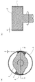
- FIG. 1A is a cross-sectional view perpendicular to the rotation axis of a grinding mill that can be used in the mechanochemical method
- FIG. 1B is a cross-sectional view taken along line A-A ′ of FIG.
- FIG. 2 is a graph showing excitation and emission spectra of the YAG phosphor.
- FIG. 3 is a graph showing the relationship between temperature and relative light emission intensity.
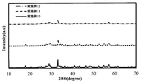
- FIG. 4 is a graph showing the XRD analysis results when the process conditions of the mechanochemical method were changed (Examples 10 to 12).
- the method for producing an inorganic compound of the present invention is characterized in that a mixture containing a raw material powder containing two or more metal oxide powders and a flux is treated by a mechanochemical method and the raw material powders are reacted with each other.
- the mechanochemical method can be performed by shearing a mixture containing raw material powder while compressing it under dry conditions, whereby strain energy is accumulated in the raw material powder, and the energy is self-released. It is used for thermal energy, surface modification, crystal structure transition, or solid phase reaction.
- the raw material powder is mechanochemically treated in the presence of the flux, and a liquid phase is generated on the surface of the raw material by the generated energy to promote the reaction between the raw material powders.
- the target inorganic compound can be obtained in a very short time only by mechanochemical treatment without performing high-temperature heat treatment.
- a compound having high crystallinity can be obtained, and in the present invention using a metal oxide as a raw material, a crystalline composite metal oxide can be obtained.
- the crystalline composite metal oxide include Ca 2 SiO 4 , Sr 2 SiO 4 , Zr 2 SiO 4 , SrAl 2 O 4 , Ba 3 MgSi 2 O 8 , Li 4 Ti 5 O 12 , and Li 2 Ti 3 O 7.
- material characteristics can also be improved by baking the obtained inorganic compound (especially crystalline composite oxide).
- a processed product after processing by a mechanochemical method when the target inorganic compound is a YAG phosphor, for example, YAG particles and / or YAG phosphor is included), a single phase is formed at a low temperature. As a result, particle growth is promoted and luminous efficiency is improved.
- Examples of the flux include metal hydroxides, metal oxides, and metal halides. All of these have the effect of generating a liquid phase between the metal oxide powders of the raw material and increasing the contact area. By using such a flux, the reaction between the raw material powders by the mechanochemical method can be performed. It becomes possible.
- Examples of the metal hydroxide include Al (OH) 3 , KOH, Sr (OH) 2 , NaOH, Ba (OH) 2 , Mg (OH) 2, and LiOH, and at least one of these is used. be able to.
- a preferred metal hydroxide is Al (OH) 3 .
- Examples of the metal oxide include PbO and B 2 O 3 .
- the metal halide is preferably a metal fluoride or metal chloride.
- the metal examples include alkali metal, alkaline earth metal, Be, Mg, Y, Al, Pb, Bi, and Zn.
- the metal halide is preferably a metal fluoride, more preferably at least one selected from the group consisting of BaF 2 , YF 3 , AlF 3 and SrF 3 , and particularly preferably BaF 2 .
- the melting point of the flux is, for example, 200 to 1400 ° C.
- the volume-based D 50 is, for example, 200 nm to 7 ⁇ m (preferably 300 nm to 6 ⁇ m, more preferably 400 nm to 5 ⁇ m).
- the amount of the flux can be appropriately set in consideration of the balance with the type of raw material powder to be used and the conditions of the mechanochemical treatment. For example, it can be 4 to 15% by mass with respect to the total amount of the raw material powder.
- FIG. 1 is a schematic view of a grinding mill that can apply a compressive force and a shearing force to a mixture of raw material powders
- FIG. 1 (a) is a cross-sectional view perpendicular to the rotation axis
- FIG. FIG. 2 is a cross-sectional view taken along the line AA ′ of FIG.
- the grinding mill shown in FIG. 1 includes a bottomed cylindrical container 1 and a rotor 2.
- the rotor 2 has a tip wing 3 having a smaller curvature than the inner periphery of the bottomed cylindrical container 1, and a clearance 4 is provided between the tip wing 3 and the inner periphery of the bottomed cylindrical container 1. . Then, by rotating the rotor 2, the raw material powder mixture 5 receives a compressive force and a shear force at the clearance 4.
- the conditions of the mechanochemical treatment are appropriately set according to the type and amount of raw materials and the flux, and can be as follows, for example.
- the range of the clearance varies depending on the amount of the raw material powder and the difference between the curvature of the tip of the rotor and the curvature of the inner circumference of the container, but can be, for example, 20 mm or less. By doing in this way, compressive force and shear force can fully be given to the mixture of raw material powder, and reaction of raw material powder is accelerated
- the clearance is preferably 10 mm or less, more preferably 5 mm or less, and particularly preferably 3 mm or less.
- the lower limit of the clearance is, for example, 100 ⁇ m, and preferably 1 mm.
- the rotational power of the rotor is, for example, 0.05 kW / g or more with respect to the total mass of the raw material powder.
- the rotational power is preferably 0.06 kW / g or more, more preferably 0.08 kW / g or more, and particularly preferably 0.1 kW / g or more.
- the upper limit of the rotational power is not particularly limited, but is, for example, 0.5 kW / g.
- the number of rotations of the rotor varies depending on the size of the device, the shape of the rotor, and the like, but if the rotational power is in the above range, it can be, for example, 1000 to 4000 rpm, preferably 2000 to 3000 rpm.
- the rotation time of the rotor can be set as appropriate depending on the rotational power of the rotor, and is, for example, 5 minutes or more (preferably 10 minutes or more). By rotating the rotor for 5 minutes or more, sufficient compression force and shearing force can be applied to the raw material powder, so that the solid-phase reaction of the raw material powder proceeds and the target compound can be obtained.
- the upper limit of the rotation time of the rotor is not particularly limited, but if it is too long, the crystallinity of the target compound will be reduced, and extra energy will be consumed, so it may be about 10 minutes, or 30 minutes or less. . However, if the rotational power of the rotor is 0.1 kW / g or more, an inorganic compound with high crystallinity can be obtained without heat treatment even for a very short time of 20 minutes or less.
- strain energy is accumulated in the raw material powder due to shearing, and the energy is self-released and becomes heat energy, which generates heat.
- the mechanochemical treatment may be performed in an exothermic state, or may be performed by cooling with water cooling or the like.
- the ultimate temperature of the cylindrical container can be set to about 130 to 500 ° C., for example.
- the atmosphere of the mechanochemical treatment is not particularly limited, but may be any of air, inert gas, and reducing gas. Of these, reducing gas is preferable.
- the inert gas include nitrogen, helium, and argon (particularly nitrogen gas is preferable).
- the reducing gas include a mixed gas of the inert gas (particularly nitrogen gas) and 3 to 5% hydrogen gas. Is mentioned.
- the material of the above-described bottomed cylindrical container is not particularly limited, and examples thereof include stainless steel such as SUS304, carbon steel, and the like. Or you may give the coating which an impurity does not mix in the target inorganic compound.
- the inner diameter of the container is, for example, 50 to 500 mm.
- the tip wings may be 1 or more, preferably 2 or more, and usually 8 or less.
- reaction conditions are too weak, the reaction between the raw material powders does not occur, and if the reaction conditions are too strong, the crystals once formed are not preferable. If the conditions of the mechanochemical treatment are inappropriate, the appropriate reaction conditions can be easily set by changing the conditions as appropriate according to the reason (unreacted, amorphized, etc.). For example, the optimum conditions in the following cases are as follows.
- the rotational power of the rotor is preferably 0.1 kW / g or more with respect to the total amount of the raw material powder, and is preferably rotated for 20 minutes or more. By doing so, it is possible to obtain a phosphor having the same characteristics (particularly, internal quantum yield when excited with light having a wavelength of 450 to 460 nm) as a phosphor obtained by a conventional firing method.
- a YAG either using Al (OH) 3 as a flux, or BaF 2, YF 3, it is preferable to use a AlF 3 or SrF 3, Al (OH) 3 or BaF 2 is preferred.
- the amount of Al (OH) 3 is preferably 4 to 15% by mass (more preferably 10 to 15% by mass) with respect to the total amount of the raw material powder, and the volume-based D 50 is preferably 400 to 800 nm.
- the ultimate temperature of the cylindrical container after the mechanochemical treatment is preferably 300 to 450 ° C. (more preferably 340 to 440 ° C.).
- the amount of BaF 2 , YF 3 , AlF 3 or SrF 3 is preferably 4 to 12% by mass, more preferably 4 to 10% by mass (particularly 5 to 8% by mass) with respect to the total amount of the raw material powder. .
- the volume-based D 50 of BaF 2 , YF 3 , AlF 3 or SrF 3 is, for example, 4 to 10 ⁇ m, preferably 5 to 9 ⁇ m, more preferably 6 to 8 ⁇ m.
- the ultimate temperature of the cylindrical container after the mechanochemical treatment is preferably 100 to 300 ° C. (more preferably 140 to 270 ° C.).
- the ultimate temperature of the cylindrical container after the mechanochemical treatment can vary depending on the power of the mechanochemical treatment, the amount of raw material powder and flux, temperature, humidity, and the like.
- the ratio of the YAG phosphor contained in the product processed by the mechanochemical method can be 3% by mass or more of the entire processed product (after treatment with an acid described later).
- the proportion of the YAG phosphor is preferably 15% by mass or more, more preferably 30% by mass or more.
- the upper limit is not particularly limited and is preferably 100% by mass, but may be about 40% by mass or less.
- an inorganic compound synthesized by a mechanochemical method may be further calcined.
- the metal oxide powder is reacted particularly by mechanochemical treatment, and then the flux is reacted with an acid. Is preferably removed.
- the acid inorganic acids such as hydrochloric acid and sulfuric acid can be used.
- the treatment with an acid may be, for example, 1 to 3 hours.
- the temperature is about 100 to 400 ° C. (preferably 200 to 300 ° C.) for 1 hour or more (preferably 2 hours or more, More preferably, it is 3 hours or longer, more preferably 4 hours or longer, usually 10 hours or shorter) to remove water sufficiently.
- an inorganic compound synthesized by a mechanochemical method in particular, YAG (that is, YAG phosphor and / or YAG particles) is fired, and more specifically, a treated product treated by the mechanochemical method is fired to improve characteristics.
- YAG that is, YAG phosphor and / or YAG particles
- inorganic compounds such as YAG phosphors obtained by mechanochemicals are made into composite particles, bonding between the particles is strong and promotes a solid phase reaction.
- the ratio of the YAG phase of the YAG phosphor and / or the YAG particles is preferably 3% by mass or more in terms of the ratio of the whole processed product after being processed by the mechanochemical method.
- it is 30% by mass or more, and the upper limit is not particularly limited and is preferably 100% by mass.
- it is usually 80% by mass and may be about 60% by mass.
- the firing temperature is preferably 1000 ° C. to 1800 ° C., more preferably 1200 ° C. to 1700 ° C., and even more preferably 1500 ° C. to 1600 ° C.
- the firing time is preferably 1 to 6 hours, more preferably 3 hours.
- the firing atmosphere is not particularly limited and may be any of air, an inert gas, and a reducing gas, but an inert gas or a reducing gas is preferable.
- the inert gas include nitrogen, helium, and argon (particularly nitrogen gas is preferable).
- the reducing gas include a mixed gas of the inert gas (particularly nitrogen gas) and 3 to 5% hydrogen gas. Is mentioned.
- the pressure during firing is preferably atmospheric pressure.
- the acid inorganic acids such as hydrochloric acid and sulfuric acid can be used.
- the treatment with an acid may be, for example, 1 to 3 hours.
- the temperature is about 100 to 400 ° C. (preferably 200 to 300 ° C.) for 1 hour or more (preferably 2 hours or more, More preferably 3 hours or more, still more preferably 4 hours or more, and usually 10 hours or less) to remove water sufficiently.
- the target inorganic compound and its raw material are as follows.
- Ca 2 SiO 4 CaCO 3 , SiO 2 Sr 2 SiO 4 : SrCO 3 , SiO 2 SrAl 2 O 4 : SrCO 3 , Al 2 O 3 Ba 3 MgSi 2 O 8 : BaCO 3 , MgO, SiO 2 Li 4 Ti 5 O 12 : Li 2 O, Li 2 CO 3 , TiO 2 Li 2 Ti 3 O 7 : Li 2 O, Li 2 CO 3 , TiO 2 LiCoO 2 : Li 2 O, Li 2 CO 3 , Co 2 O 3 SrTiO 3 : SrCO 3 , TiO 2 LaSrMnO 3 : La 2 O 3 , SrCO 3 , MnO 2 NaCo 2 O 4 : Na 2 O, Co 2 O 3 Ca 3 Co 4 O 9 : CaCO 3 , Co 2 O 3 Bi 2 Sr 2 Co 2 O y : BiO 2 , SrCO 3 , Co 2 O 3 Zr 2 SiO 4 : ZrO, SiO 2 YAG
- the YAG phosphor obtained by the production method of the present invention is a YAG phosphor containing a YAG crystal as a mother crystal and containing at least one dopant selected from the group consisting of Ce, Tb, Eu, Yb, Pr, Tm and Sm. It is.
- the YAG phosphor can be represented by the composition formula of Y 3-x M x Al 5 O 12.
- M is the above dopant element, a component that substitutes Y and becomes a light emission center, and is also called an activator.
- the dopant is preferably at least one selected from the group consisting of Ce, Tb and Yb, and Ce is particularly preferable.
- the x is a value satisfying 0 ⁇ x ⁇ 1.
- the volume-based D 50 of the YAG phosphor is, for example, 600 nm to 20 ⁇ m.
- the value of x should be 0.003 to 0.2. If the value of x is less than 0.003, fluorescence with sufficient emission intensity cannot be obtained. On the other hand, when the value of x exceeds 0.2, energy transfer occurs between the activators and concentration quenching occurs. Concentration quenching means that the intensity of fluorescence increases as the concentration of the activator increases because energy transfer between adjacent molecules occurs and the original energy is not sufficiently emitted as fluorescence (non-luminescent transition). It is a phenomenon that does not happen.
- the value of x is preferably 0.01 to 0.2. By setting x to 0.01 or more, a phosphor having an emission intensity suitable for use in a light emitting device is obtained.
- the fluorescence is equivalent to or higher than the YAG phosphor obtained by the conventional firing method in a very short time.
- a YAG phosphor having characteristics can be obtained.
- the internal quantum yield (25 ° C.) when excited with light having a wavelength of 450 to 460 nm can be 40% or more, preferably 50% or more, and more preferably 60% or more.
- the internal quantum yield of 60% or more is almost the same as that of the phosphor obtained by the conventional firing method.
- the YAG phosphor of the present invention is a polycrystal, and the half width of the (400) plane diffraction peak in the XRD analysis is preferably 0.1 to 0.8 °.
- the diffraction peak of the (400) plane is the YAG phase, and the fact that the half width of the diffraction peak of the YAG phase is in the above range means that the crystallinity of the phosphor is high.
- the half width is preferably 0.7 ° or less, and more preferably 0.4 ° or less.
- the YAG phosphor produced according to the present invention may include a YAP (YAlO 3 ) phase in addition to the YAG phase.
- the surface index of the YAlO 3 phase is (121), and a diffraction peak appears around 34 °.
- the ratio of the (400) plane diffraction peak intensity to the total of the (121) plane diffraction peak intensity and the (400) plane diffraction peak intensity is, for example, 20% or more, preferably Is 30% or more, more preferably 40% or more.
- the upper limit of the diffraction peak intensity ratio is most preferably 100%, and may be about 80% or less.
- YAG particles Y 3 Al 5 O 12 in which a light emitting element is not dissolved
- the external quantum efficiency at 25 ° C. when excited with light having a wavelength of 450 to 460 nm is preferably 20% or more, more preferably 30% or more, and further preferably 40% or more.
- the upper limit of the external quantum efficiency is not particularly limited, but is usually about 60%.
- the absorptance at a wavelength of 450 to 460 nm is preferably 45% or more, and more preferably 50% or more.
- the upper limit of the absorption rate is not particularly limited, but is about 75%, for example.
- the YAG phosphor of the present invention has an emission intensity at 150 ° C. (hereinafter referred to as “temperature quenching characteristic at 150 ° C.”) with respect to the emission intensity at 25 ° C. when excited with light having a wavelength of 450 to 460 nm, for example, 70. It is ⁇ 95%, preferably 80% or more, more preferably 90% or more.
- the emission intensity at 200 ° C. relative to the emission intensity at 25 ° C. when excited with light having a wavelength of 450 to 460 nm (hereinafter “temperature quenching characteristic at 200 ° C.”) is, for example, 65 to 90%. Preferably it is 70% or more, more preferably 80% or more (especially 85% or more).
- the YAG phosphor of the present invention is efficiently excited in the near ultraviolet to visible light region and emits yellow light.
- the wavelength of the excitation light is preferably 265 to 470 nm, more preferably 365 to 470 nm, and still more preferably 450 to 460 nm.
- the peak of the emission wavelength when the YAG phosphor of the present invention is excited with light having a wavelength of 450 to 460 nm is, for example, 540 to 600 nm. It has also been confirmed that yellow light is emitted when excited by vacuum ultraviolet rays of 100 to 190 nm, ultraviolet rays of 190 to 380 nm, electron beams and the like.
- a light emitting device comprising a light emitting element such as an LED or LD made of a nitride semiconductor that emits ultraviolet to blue (particularly blue) light, and the YAG phosphor of the present invention, wherein the light from the light emitting element is used as excitation light
- the light-emitting device that emits yellow light from the YAG phosphor of the present invention can be a high-power (for example, 5 W or more) light-emitting device because the temperature quenching characteristics of the YAG phosphor of the present invention are good.
- Examples of such a light emitting device include a fluorescent display tube (VFD), a field emission display (FED), a plasma display panel (PDP), and a cathode ray tube (CRT).
- Example 1 As a raw material of the YAG phosphor, Y 2 O 3 (manufactured by high purity chemical, volume-based D 50 : 0.6 ⁇ m), Al 2 O 3 (manufactured by high purity chemical, volume-based D 50 : 0.4 ⁇ m), CeO 2 Weighing 30 g in total in a stoichiometric ratio in which the composition of the phosphor to be produced is Y 2.97 Ce 0.03 Al 5 O 12 , each of powders of high purity chemical (volume-based D 50 : 0.3 ⁇ m), 12.5 wt% of Al (OH) 3 (manufactured by Showa Denko Hygielite H43M, volume-based D 50 : 0.75 ⁇ m) was added to the milling mill shown in FIG.
- the bottomed cylindrical container 1 is made of SUS304, has an inner diameter of 80 mm, and the clearance 4 between the inner periphery of the container 1 and the tip blade of the rotor 2 is 1 mm.
- Such a grinding mill was rotated at a rotational speed of 3000 rpm and a required power of 3 kW for 30 minutes to perform mechanochemical treatment.
- the temperature of the milling mill at that time was 350 ° C.
- the mixture was stirred in dilute hydrochloric acid for 2 hours, washed with pure water, and then heated to 170 ° C. to sufficiently remove moisture to obtain phosphor powder.
- the crystals of the obtained phosphor powder are polycrystalline YAG and YAP (YAlO 3 ) composite particles, and the (400) plane diffraction peak intensity and the (121) plane diffraction peak intensity are (400 The ratio of diffraction peak intensities on the surface) was 30.6%.
- the YAG phase was 3.6 wt%.
- the half width of the (400) plane was 0.668 °.
- the emission characteristics of the obtained phosphor powder were measured under the conditions of excitation side slit: 2.5 nm, fluorescence side slit: 2.5 nm, and photomultiplier voltage 350 V using Hitachi High-Tech F-7000 type spectrofluorophotometer. It was measured. As a result, yellow light emission having an excitation spectrum of about 365 to 500 nm and an emission spectrum peak around 550 nm was confirmed. Subsequently, quantum yield measurement and temperature quenching measurement were performed using an absolute quantum yield measuring apparatus (Quantaurus-QY C11347-01) manufactured by Hamamatsu Photonics. As a result, the internal quantum yield at 25 ° C. when the wavelength of the excitation light was 450 nm was 27.3%, and the emission intensity at 150 ° C. was 86% with respect to the emission intensity at 25 ° C.
- Example 2 A phosphor powder was obtained in the same manner as in Example 1 except that the ultimate temperature of the milling mill was 438 ° C.
- the crystals of the obtained phosphor powder are polycrystalline YAG and YAP composite particles, and the diffraction peak intensity on the (400) plane
- the ratio of the diffraction peak intensity of the (400) plane to the sum of the diffraction peak intensity of the (121) plane was 48.9%.
- the YAG phase was 15.5 wt%.
- the half width of the (400) plane was 0.158 °.
- the emission characteristics of the obtained phosphor powder were measured in the same manner as in Example 1. As a result, yellow emission having an excitation spectrum of about 365 to 500 nm and having an emission spectrum peak around 550 nm was confirmed.
- the internal quantum yield at 25 ° C. when the wavelength of the excitation light was 450 nm was 13.2%, and the emission intensity at 150 ° C. was 83% with respect to the emission intensity at 25 ° C.
- Example 3 As a raw material of the YAG phosphor, Y 2 O 3 (manufactured by high purity chemical, volume-based D 50 : 0.6 ⁇ m), Al 2 O 3 (manufactured by high purity chemical, volume-based D 50 : 0.4 ⁇ m), CeO 2 Weighing 30 g in total in a stoichiometric ratio in which the composition of the phosphor to be produced is Y 2.97 Ce 0.03 Al 5 O 12 , each of powders of high purity chemical (volume-based D 50 : 0.3 ⁇ m), 6 wt% of BaF 2 (volume-based D 50 : 6 ⁇ m) was added and charged into the grinding mill shown in FIG.
- the chamber container of the milling mill was water-cooled at 1 L / min.
- the bottomed cylindrical container 1 is made of SUS304, has an inner diameter of 80 mm, and the clearance 4 between the inner periphery of the container 1 and the tip blade of the rotor 2 is 1 mm.
- Such a grinding mill was rotated for 10 minutes at a rotational speed of 3000 rpm and a required power of 3 kW to perform mechanochemical treatment.
- the temperature of the milling mill at that time was 114 ° C.
- the mixture was stirred in dilute hydrochloric acid for 2 hours, washed with pure water, and then heated to 170 ° C. to sufficiently remove moisture to obtain phosphor powder.
- the crystals of the obtained phosphor powder are polycrystalline YAG and YAP composite particles, and the diffraction peak intensity on the (400) plane
- the ratio of the diffraction peak intensity of the (400) plane to the sum of the diffraction peak intensities of the (121) plane was 70.7%.
- the YAG phase was 31.5 wt%.
- the half width of the (400) plane was 0.224 °.
- the emission characteristics of the obtained phosphor powder were measured in the same manner as in Example 1. As a result, yellow emission having an excitation spectrum of about 365 to 500 nm and an emission spectrum peak around 540 nm was confirmed. Further, the internal quantum yield at 25 ° C. when the wavelength of the excitation light was 450 nm was 32.5%, and the emission intensity at 150 ° C. was 85% with respect to the emission intensity at 25 ° C.
- Example 4 A phosphor powder was obtained in the same manner as in Example 3 except that the milling mill was not cooled with water. The temperature of the milling mill at that time was 210 ° C.
- the crystal structure and light emission characteristics of the obtained phosphor powder were measured by the same method as in Example 1.
- the phosphor powder crystals are polycrystalline YAG and YAP composite particles, and the (400) plane diffraction peak intensity is the sum of the (400) plane diffraction peak intensity and the (121) plane diffraction peak intensity.
- the ratio was 25.9%.
- the half width of the (400) plane was 0.326 °.
- yellow light emission having an excitation spectrum of about 365 to 500 nm and an emission spectrum peak around 540 nm was confirmed, the internal quantum yield at 25 ° C. was 51.8%, and the emission intensity at 150 ° C. was It was 84%.
- Example 5 A phosphor powder was obtained in the same manner as in Example 4 except that the treatment time was 15 minutes. The temperature of the milling mill at that time was 217 ° C.
- the crystal structure and light emission characteristics of the obtained phosphor powder were measured by the same method as in Example 1.
- the phosphor powder crystals are polycrystalline YAG and YAP composite particles, and the (400) plane diffraction peak intensity is the sum of the (400) plane diffraction peak intensity and the (121) plane diffraction peak intensity.
- the ratio was 28.9%.
- the half width of the (400) plane was 0.639 °.
- yellow light emission having an excitation spectrum of about 365 to 500 nm and an emission spectrum peak around 540 nm was confirmed, the internal quantum yield at 25 ° C. was 55.2%, and the emission intensity at 150 ° C. was 90%.
- Example 6 A phosphor powder was obtained in the same manner as in Example 4 except that the treatment time was 20 minutes. The temperature of the milling mill at that time was 210 ° C.
- the crystal structure and light emission characteristics of the obtained phosphor powder were measured by the same method as in Example 1.
- the phosphor powder crystals are polycrystalline YAG and YAP composite particles, and the (400) plane diffraction peak intensity is the sum of the (400) plane diffraction peak intensity and the (121) plane diffraction peak intensity.
- the ratio was 32.3%.
- the half width of the (400) plane was 0.386 °.
- yellow light emission having an excitation spectrum of about 365 to 500 nm and an emission spectrum peak around 540 nm was confirmed, the internal quantum yield at 25 ° C. was 60.8%, and the emission intensity at 150 ° C. was It was 88%.
- Example 7 A phosphor powder was obtained in the same manner as in Example 4 except that the treatment time was 10 minutes. The temperature of the milling mill at that time was 255 ° C.
- the crystal structure and light emission characteristics of the obtained phosphor powder were measured by the same method as in Example 1.
- the phosphor powder crystals are polycrystalline YAG and YAP composite particles, and the (400) plane diffraction peak intensity is the sum of the (400) plane diffraction peak intensity and the (121) plane diffraction peak intensity.
- the ratio was 62.6%.
- the half width of the (400) plane was 0.333 °.
- yellow light emission having an excitation spectrum of about 365 to 500 nm and an emission spectrum peak around 540 nm was confirmed, the internal quantum yield at 25 ° C. was 56.5%, and the emission intensity at 150 ° C. was It was 88%.
- Example 8 A phosphor powder was obtained in the same manner as in Example 4 except that the treatment time was 15 minutes. The temperature of the milling mill at that time was 270 ° C.
- the crystal structure and light emission characteristics of the obtained phosphor powder were measured by the same method as in Example 1.
- the phosphor powder crystals are polycrystalline YAG and YAP composite particles, and the (400) plane diffraction peak intensity is the sum of the (400) plane diffraction peak intensity and the (121) plane diffraction peak intensity.
- the ratio was 64.2%.
- the half width of the (400) plane was 0.299 °.
- yellow light emission having an excitation spectrum of about 365 to 500 nm and an emission spectrum peak around 540 nm was confirmed, the internal quantum yield at 25 ° C. was 54.9%, and the emission intensity at 150 ° C. was It was 89%.
- Example 9 A phosphor powder was obtained in the same manner as in Example 4 except that the treatment time was 20 minutes. The temperature of the milling mill at that time was 270 ° C.
- the crystal structure and light emission characteristics of the obtained phosphor powder were measured by the same method as in Example 1.
- the phosphor powder crystals are polycrystalline YAG and YAP composite particles, and the (400) plane diffraction peak intensity is the sum of the (400) plane diffraction peak intensity and the (121) plane diffraction peak intensity.
- the ratio was 59.9%.
- the half width of the (400) plane was 0.395 °.
- yellow light emission having an excitation spectrum of about 365 to 500 nm and an emission spectrum peak around 540 nm was confirmed, the internal quantum yield at 25 ° C. was 54.5%, and the emission intensity at 150 ° C. was 90%.
- Example 10 A phosphor powder was obtained in the same manner as in Example 4 except that the treatment time was 10 minutes and the addition amount of BaF 2 was 10 wt%. The temperature of the milling mill at that time was 140 ° C.
- the crystal structure and light emission characteristics of the obtained phosphor powder were measured by the same method as in Example 1.
- the phosphor powder crystals are polycrystalline YAG and YAP composite particles, and the (400) plane diffraction peak intensity is the sum of the (400) plane diffraction peak intensity and the (121) plane diffraction peak intensity.
- the ratio was 77.2%.
- the half width of the (400) plane was 0.232 °.
- yellow light emission having an excitation spectrum of about 365 to 500 nm and an emission spectrum peak around 540 nm was confirmed, the internal quantum yield at 25 ° C. was 33.3%, and the emission intensity at 150 ° C. was It was 84%.
- Example 11 A phosphor powder was obtained in the same manner as in Example 10 except that the treatment time was 20 minutes.
- the crystal structure and light emission characteristics of the obtained phosphor powder were measured by the same method as in Example 1.
- the phosphor powder crystals are polycrystalline YAG and YAP composite particles, and the (400) plane diffraction peak intensity is the sum of the (400) plane diffraction peak intensity and the (121) plane diffraction peak intensity.
- the ratio was 73.5%.
- the half width of the (400) plane was 0.251 °.
- yellow light emission having an excitation spectrum of about 365 to 500 nm and an emission spectrum peak around 540 nm was confirmed, the internal quantum yield at 25 ° C. was 30.7%, and the emission intensity at 150 ° C. was It was 86%.
- Example 12 A phosphor powder was obtained in the same manner as in Example 10 except that the treatment time was 30 minutes.
- the crystal structure and light emission characteristics of the obtained phosphor powder were measured by the same method as in Example 1.
- the phosphor powder crystals are polycrystalline YAG and YAP composite particles, and the (400) plane diffraction peak intensity is the sum of the (400) plane diffraction peak intensity and the (121) plane diffraction peak intensity.
- the ratio was 73.3%.
- the half width of the (400) plane was 0.284 °.
- yellow light emission having an excitation spectrum of about 365 to 500 nm and an emission spectrum peak around 540 nm was confirmed, the internal quantum yield at 25 ° C. was 23.5%, and the emission intensity at 150 ° C. was 87%.
- Example 13 As a raw material of the YAG phosphor, Y 2 O 3 (manufactured by high purity chemical, volume-based D 50 : 0.6 ⁇ m), Al 2 O 3 (manufactured by high purity chemical, volume-based D 50 : 0.4 ⁇ m), CeO 2 Weighing 30 g in total in a stoichiometric ratio in which the composition of the phosphor to be produced is Y 2.97 Ce 0.03 Al 5 O 12 , each of powders of high purity chemical (volume-based D 50 : 0.3 ⁇ m), 6 wt% of AlF 3 (volume-based D 50 : 7 ⁇ m) was added and charged into the grinding mill shown in FIG.
- the chamber container of the milling mill was water-cooled at 1 L / min.
- the bottomed cylindrical container 1 is made of SUS304, has an inner diameter of 80 mm, and the clearance 4 between the inner periphery of the container 1 and the tip blade of the rotor 2 is 1 mm.
- Such a grinding mill was rotated for 10 minutes at a rotational speed of 3000 rpm and a required power of 2.5 kW to perform mechanochemical treatment.
- the temperature of the milling mill at that time was 74 ° C.
- the mixture was stirred in dilute hydrochloric acid for 2 hours, washed with pure water, and then heated to 170 ° C. to sufficiently remove moisture to obtain phosphor powder.
- the crystal structure and emission characteristics of the obtained phosphor powder were measured in the same manner as in Example 1. As a result, the crystals of the phosphor powder were polycrystalline YAG, Y 2 O 3 and Al 2 O 3 composite particles, and the YAP phase could not be confirmed.
- the half width of the (400) plane was 0.355 °. Further, yellow light emission having an excitation spectrum of about 365 to 500 nm and an emission spectrum peak around 540 nm was confirmed, the internal quantum yield at 25 ° C. was 30.5%, and the emission intensity at 150 ° C. was It was 84%.
- Example 14 A phosphor powder was obtained in the same manner as in Example 13 except that 10 wt% of AlF 3 was added. The temperature of the milling mill at that time was 110 ° C.
- the crystal structure and emission characteristics of the obtained phosphor powder were measured in the same manner as in Example 1. As a result, crystals of the phosphor powder is a composite particle of the YAG polycrystal and Y 2 O 3, Al 2 O 3, YAP phase could not be confirmed.
- the half width of the (400) plane was 0.492 °.
- yellow light emission having an excitation spectrum of about 365 to 500 nm and an emission spectrum peak around 540 nm was confirmed, the internal quantum yield at 25 ° C. was 45.3%, and the emission intensity at 150 ° C. was It was 86%.
- Example 15 A phosphor powder was obtained in the same manner as in Example 14 except that the treatment time was 15 minutes. The temperature of the milling mill at that time was 99.5 ° C.
- the crystal structure and emission characteristics of the obtained phosphor powder were measured in the same manner as in Example 1. As a result, the crystals of the phosphor powder were polycrystalline YAG, Y 2 O 3 and Al 2 O 3 composite particles, and the YAP phase could not be confirmed. Further, the half width of the (400) plane was 0.335 °. Further, yellow light emission having an excitation spectrum of about 365 to 500 nm and an emission spectrum peak around 540 nm was confirmed, the internal quantum yield at 25 ° C. was 46.7%, and the emission intensity at 150 ° C. was 87%.
- Example 16 As a raw material of the YAG phosphor, Y 2 O 3 (manufactured by high purity chemical, volume-based D 50 : 0.6 ⁇ m), Al 2 O 3 (manufactured by high purity chemical, volume-based D 50 : 0.4 ⁇ m), CeO 2 Weighing 30 g in total in a stoichiometric ratio in which the composition of the phosphor to be produced is Y 2.97 Ce 0.03 Al 5 O 12 , each of powders of high purity chemical (volume-based D 50 : 0.3 ⁇ m), 6 wt% of YF 3 (volume-based D 50 : 6 ⁇ m) was added to the milling mill shown in FIG.
- the chamber container of the milling mill was water-cooled at 1 L / min.
- the bottomed cylindrical container 1 is made of SUS304, has an inner diameter of 80 mm, and the clearance 4 between the inner periphery of the container 1 and the tip blade of the rotor 2 is 1 mm.
- Such a grinding mill was rotated for 10 minutes at a rotational speed of 3000 rpm and a required power of 3 kW to perform mechanochemical treatment.
- the temperature of the milling mill at that time was 140 ° C.
- the mixture was stirred in dilute hydrochloric acid for 2 hours, washed with pure water, and then heated to 170 ° C. to sufficiently remove moisture to obtain phosphor powder.
- the crystal structure and emission characteristics of the obtained phosphor powder were measured in the same manner as in Example 1. As a result, the crystals of the phosphor powder were polycrystalline YAG, Y 2 O 3 and Al 2 O 3 composite particles, and the YAP phase could not be confirmed. Further, the half width of the (400) plane was 0.296 °. Further, yellow light emission having an excitation spectrum of about 365 to 500 nm and an emission spectrum peak around 540 nm was confirmed, the internal quantum yield at 25 ° C. was 11.5%, and the emission intensity at 150 ° C. was It was 73%.
- Example 17 A phosphor powder was obtained in the same manner as in Example 16 except that the treatment time was 15 minutes. The temperature of the milling mill at that time was 137 ° C.
- the crystal structure and emission characteristics of the obtained phosphor powder were measured in the same manner as in Example 1. As a result, the crystals of the phosphor powder were polycrystalline YAG, Y 2 O 3 and Al 2 O 3 composite particles, and the YAP phase could not be confirmed.
- the half width of the (400) plane was 0.341 °. Further, yellow light emission having an excitation spectrum of about 365 to 500 nm and an emission spectrum peak around 540 nm was confirmed, the internal quantum yield at 25 ° C. was 41.2%, and the emission intensity at 150 ° C. was It was 86%.
- Example 18 A phosphor powder was obtained in the same manner as in Example 16 except that the amount of YF 3 added was 10 wt%. The temperature of the milling mill at that time was 118 ° C.
- the crystal structure and emission characteristics of the obtained phosphor powder were measured in the same manner as in Example 1. As a result, the crystals of the phosphor powder were polycrystalline YAG, Y 2 O 3 and Al 2 O 3 composite particles, and the YAP phase could not be confirmed. Further, the half width of the (400) plane was 0.350 °. In addition, yellow light emission having an excitation spectrum of about 365 to 500 nm and an emission spectrum peak around 540 nm was confirmed, the internal quantum yield at 25 ° C. was 57.8%, and the emission intensity at 150 ° C. was It was 88%.
- Example 19 A phosphor powder was obtained in the same manner as in Example 18 except that the treatment time was 15 minutes. The temperature of the milling mill at that time was 87 ° C.
- the crystal structure and emission characteristics of the obtained phosphor powder were measured in the same manner as in Example 1. As a result, the crystals of the phosphor powder were polycrystalline YAG, Y 2 O 3 and Al 2 O 3 composite particles, and the YAP phase could not be confirmed.
- the half width of the (400) plane was 0.313 °. Further, yellow light emission having an excitation spectrum of about 365 to 500 nm and an emission spectrum peak around 540 nm was confirmed, the internal quantum yield at 25 ° C. was 57.3%, and the emission intensity at 150 ° C. was It was 89%.
- Comparative Example 1 The mechanochemical treatment was performed in the same manner as in Example 10 except that the treatment time was 30 minutes and no flux was added.
- the crystal structure of the obtained powder was measured in the same manner as in Example 1. As a result, the formation of the YAG ⁇ YAP phase was not confirmed, and the diffraction patterns of the raw materials Y 2 O 3 , Al 2 O 3 , and CeO 2 were confirmed.
- Tables 1 and 2 show the test conditions and results of Examples 1 to 19 and Comparative Example 1.
- Table 2 also shows the temperature quenching characteristics at 200 ° C., the external quantum yield when excited with light having a wavelength of 450 to 460 nm, and the absorptance of light having a wavelength of 450 to 460 nm.
- FIG. 2 is a graph showing excitation spectra and emission spectra of Examples 6, 15, and 18. In any case, yellow light emission having an excitation spectrum of about 365 to 500 nm and an emission spectrum peak around 540 nm has been confirmed.
- FIG. 3 is a graph obtained by measuring and plotting the luminescence intensity when the temperature is changed to 200 ° C. in Examples 5 to 9 (the luminescence intensity at 25 ° C. in each example is 100). . In any of the examples, it can be seen that a good temperature quenching characteristic of 80% or more at 200 ° C. is exhibited.
- FIG. 4 is a graph showing the XRD analysis results of Examples 10 to 12, and it is observed that the crystallinity tends to be relatively higher when the fluoride is added and the treatment time is shorter.
- Example 20 As a raw material of the YAG phosphor, Y 2 O 3 (manufactured by high purity chemical, volume-based D 50 : 0.6 ⁇ m), Al 2 O 3 (manufactured by high purity chemical, volume-based D 50 : 0.4 ⁇ m), CeO 2 Weighing 30 g in total in a stoichiometric ratio in which the composition of the phosphor to be produced is Y 2.97 Ce 0.03 Al 5 O 12 , each of powders of high purity chemical (volume-based D 50 : 0.3 ⁇ m), 6 wt% of BaF 2 (volume-based D 50 : 6 ⁇ m) was added and charged into the grinding mill shown in FIG.
- the chamber container of the milling mill was water-cooled at 1 L / min.
- the bottomed cylindrical container 1 is made of SUS304, has an inner diameter of 80 mm, and the clearance 4 between the inner periphery of the container 1 and the tip blade of the rotor 2 is 1 mm.
- Such a grinding mill was rotated for 20 minutes at a rotational speed of 3000 rpm and a required power of 3 kW to perform mechanochemical treatment.
- the temperature of the milling mill at that time was 210 ° C.
- Example 21 A YAG phosphor was obtained in the same manner as in Example 20 except that the firing temperature was 1500 ° C. The crystal structure and emission characteristics of the obtained phosphor powder were measured in the same manner as in Example 1. As a result, it was confirmed that a YAG single phase was obtained. The full width at half maximum of the (400) plane was 0.157 °. Further, yellow light emission having an excitation spectrum of about 365 to 500 nm and an emission spectrum peak around 540 nm was confirmed, the internal quantum yield at 25 ° C. was 80.9%, and the emission intensity at 150 ° C. was 95%.
- Example 22 As a raw material of the YAG phosphor, Y 2 O 3 (manufactured by high purity chemical, volume-based D 50 : 0.6 ⁇ m), Al 2 O 3 (manufactured by high purity chemical, volume-based D 50 : 0.4 ⁇ m), CeO 2 Weighing 30 g in total in a stoichiometric ratio in which the composition of the phosphor to be produced is Y 2.97 Ce 0.03 Al 5 O 12 , each of powders of high purity chemical (volume-based D 50 : 0.3 ⁇ m), AlF 3 (volume-based D 50 : 7 ⁇ m) was added at 10 wt%, and the mixture was put into the grinding mill shown in FIG.
- the chamber container of the milling mill was water-cooled at 1 L / min.
- the bottomed cylindrical container 1 is made of SUS304, has an inner diameter of 80 mm, and the clearance 4 between the inner periphery of the container 1 and the tip blade of the rotor 2 is 1 mm.
- Such a grinding mill was rotated for 15 minutes at a rotational speed of 3000 rpm and a required power of 2.5 kW to perform mechanochemical treatment.
- the temperature of the milling mill at that time was 99.5 ° C. 5 g of the obtained processed product was put into an alumina crucible and fired at 1200 ° C. for 3 hours in a graphite furnace.
- the firing atmosphere was a nitrogen gas atmosphere.
- the mixture was stirred in dilute hydrochloric acid for 2 hours, washed with pure water, and then heated to 170 ° C. to sufficiently remove moisture, thereby obtaining a phosphor powder.
- the crystal structure and emission characteristics of the obtained phosphor powder were measured in the same manner as in Example 1. As a result, it was confirmed that a YAG single phase was obtained.
- the full width at half maximum of the (400) plane was 0.236 °. Further, yellow light emission having an excitation spectrum of about 365 to 500 nm and an emission spectrum peak around 540 nm was confirmed, the internal quantum yield at 25 ° C. was 60.5%, and the emission intensity at 150 ° C. was 90%.
- Example 23 A phosphor powder was obtained in the same manner as in Example 22 except that the firing temperature was 1500 ° C. The crystal structure and emission characteristics of the obtained phosphor powder were measured in the same manner as in Example 1. As a result, it was confirmed that a YAG single phase was obtained. The full width at half maximum of the (400) plane was 0.156 °, and yellow light emission having an excitation spectrum of about 365 to 500 nm and an emission spectrum peak around 540 nm was confirmed, and the internal quantum at 25 ° C. The yield was 70.2%, and the emission intensity at 150 ° C. was 94%.
- Example 24 As a raw material of the YAG phosphor, Y 2 O 3 (manufactured by high purity chemical, volume-based D 50 : 0.6 ⁇ m), Al 2 O 3 (manufactured by high purity chemical, volume-based D 50 : 0.4 ⁇ m), CeO 2 Weighing 30 g in total in a stoichiometric ratio in which the composition of the phosphor to be produced is Y 2.97 Ce 0.03 Al 5 O 12 , each of powders of high purity chemical (volume-based D 50 : 0.3 ⁇ m), 10 wt% of YF 3 (volume-based D 50 : 6 ⁇ m) was added and charged into the grinding mill shown in FIG.
- the chamber container of the milling mill was water-cooled at 1 L / min.
- the bottomed cylindrical container 1 is made of SUS304, has an inner diameter of 80 mm, and the clearance 4 between the inner periphery of the container 1 and the tip blade of the rotor 2 is 1 mm.
- Such a grinding mill was rotated for 10 minutes at a rotational speed of 3000 rpm and a required power of 3 kW to perform mechanochemical treatment.
- the temperature of the milling mill at that time was 118 ° C.
- Example 25 A phosphor powder was obtained in the same manner as in Example 24 except that the firing temperature was 1500 ° C. The crystal structure and emission characteristics of the obtained phosphor powder were measured in the same manner as in Example 1. As a result, it was confirmed that a YAG single phase was obtained. The full width at half maximum of the (400) plane was 0.154 °, and yellow light emission having an excitation spectrum of about 365 to 500 nm and an emission spectrum peak around 540 nm was confirmed, and the internal quantum at 25 ° C. The yield was 72.2%, and the emission intensity at 150 ° C. was 95%.
- the method for producing an inorganic compound of the present invention does not require a high-temperature facility and does not require a pulverization step or classification after sintering, as compared with a conventional firing method. Furthermore, since synthesis is possible in a very short time, productivity is high.
- the YAG phosphor produced by the present invention is suitably used for light emitting devices such as a fluorescent display tube (VFD), a field emission display (FED), a plasma display panel (PDP), and a cathode ray tube (CRT). YAG particles are also used as an optical material and a heat-resistant material and are industrially useful.
Landscapes
- Chemical & Material Sciences (AREA)
- Organic Chemistry (AREA)
- Inorganic Chemistry (AREA)
- Life Sciences & Earth Sciences (AREA)
- Geology (AREA)
- Luminescent Compositions (AREA)
- Compounds Of Alkaline-Earth Elements, Aluminum Or Rare-Earth Metals (AREA)
Abstract
金属酸化物を原料とする無機化合物を製造する方法であって、従来のボールミル法で混合及び焼成する製造方法よりも短時間で、かつ、高温で焼成することなく目的の無機化合物を製造する方法を提供することを目的とする。 本発明は、2種以上の金属酸化物粉末を含む原料粉末と、フラックスとを含む混合物を、メカノケミカル法によって処理し、前記2種以上の金属酸化物粉末を反応させる無機化合物の製造方法である。前記反応によって得られる無機化合物が、結晶性複合金属酸化物であることが好ましい。
Description
本発明は、無機化合物の製造方法に関する。以下では、無機化合物として、蛍光体を例に挙げて説明するが、これに限定する趣旨ではない。
従来、LED(Light Emitting Diode)からなる発光素子と、この発光素子の光を受けて励起される蛍光体とを備え、発光素子が発する色と蛍光体が発する色との混合によって、白色光を放射する発光装置が知られている。具体的には、近紫外LED又は紫色LEDと、赤色、緑色、青色の蛍光体の組み合わせや、青色LEDと黄色蛍光体の組み合わせなどが知られている。例えば、特許文献1には窒化物赤色蛍光体をエポキシ樹脂等の樹脂に含ませて、発光ダイオード光源を構成するチップ上に塗布した白色発光ダイオードが開示され、特許文献2には青色の光を吸収し、黄色の蛍光を発する性質を有する多結晶体であって、該多結晶体がYAG結晶である蛍光体材料が開示されている。
例えばYAG蛍光体の製造方法としては、原料粉末であるY2O3、Al2O3、CeO2をボールミリングにより混合し、1600℃以上の高温で焼成する方法が挙げられる。焼成温度を下げる手段としては、BaF2などの焼結助剤を添加し、固相-液相反応を介して反応を促進する方法があり、これにより焼成温度を1500℃程度に低下できるとともに、粒成長も促進できる(非特許文献1)。しかし、焼結助剤を用いたとしても、千数百℃で焼成する必要があり、高温設備が必要となってコスト高となる。また、高温で焼成すると、原料がルツボに接する部分で、原料とルツボの成分が反応し、得られる蛍光体の蛍光特性を低下させてしまう。これは、製品の収率を低下させ、コスト高となるため望ましくない。また、焼結することにより、粉砕工程や、必要な粒度を揃えるための分級工程も必要となる。従って、高温で焼成することなく、機械的エネルギーのみを用いてYAG蛍光体またはYAG粒子を得ることができれば、高温設備も不要であり、かつ粉砕工程や分級工程を必要としない生産性の高い製造方法が実現でき、YAG蛍光体またはYAG粒子の低コスト化が可能となる。
機械的エネルギーを用いた工程を含むYAG蛍光体の製造方法として、特許文献3では、原料粉末を遊星ボールミルで16~24時間処理して非平衡粉末を作製し、1100℃で焼成する方法が開示されている。また、非特許文献2では、原料粉末にAl(OH)3を添加し遊星ボールミルにて6時間処理し、無定形状態(アモルファス)のYAG粒子(すなわち、発光元素が固溶していないY3Al5O12であって、発光元素の固溶したY3Al5O12であるYAG蛍光体とは区別される)を作製し、1200℃程度で焼成することで結晶化している。これらの方法は、非常に長い時間の機械的エネルギーの投入が必要であると共に、結晶化させるために熱処理を行わなければならない。つまり、機械的エネルギーのみで結晶性の高いYAG粒子又はYAG蛍光体を合成する方法は未だ達成されていない。
J.Electorochem.soc.vol.141,No.5,May1994
Powder Technology 129(2003)86-91
本発明は、上述したYAG蛍光体に代表されるような、金属酸化物を原料とする無機化合物を製造する方法であって、従来のボールミル法で混合及び焼成する製造方法よりも短時間で、かつ、高温で焼成することなく目的の無機化合物を製造する方法を提供することを目的とする。
上記課題を達成した本発明は、
(1)2種以上の金属酸化物粉末を含む原料粉末と、フラックスとを含む混合物を、メカノケミカル法によって処理し、前記2種以上の金属酸化物粉末を反応させる無機化合物の製造方法である。
(1)2種以上の金属酸化物粉末を含む原料粉末と、フラックスとを含む混合物を、メカノケミカル法によって処理し、前記2種以上の金属酸化物粉末を反応させる無機化合物の製造方法である。
(2)(1)に記載の無機化合物の製造方法は、前記メカノケミカル法によって処理した後、この処理物を更に焼成することが好ましい。
(3)(2)に記載の無機化合物の製造方法は、1800℃以下で焼成することが好ましい。
(4)(1)~(3)のいずれかに記載の無機化合物の製造方法は、前記反応によって得られる無機化合物が、結晶性複合金属酸化物であることが好ましい。
(5)(1)~(4)のいずれかに記載の無機化合物の製造方法は、前記原料粉末が、Y2O3粉末、Al2O3粉末と、Ce、Tb、Eu、Yb、Pr、Tm及びSmよりなる群から選択される少なくとも1種のドーパントの酸化物粉末を含み、前記無機化合物がYAG蛍光体であることが好ましい。
(6)(1)~(5)のいずれかに記載の無機化合物の製造方法は、メカノケミカル法によって前記2種以上の金属酸化物粉末を反応させる工程、酸により前記フラックスを除去する工程の両方を有することが好ましい。
(7)(1)~(6)のいずれかに記載の無機化合物の製造方法は、前記フラックスが、金属水酸化物、金属酸化物及び金属ハロゲン化物よりなる群から選択される少なくとも1種であることが好ましい。
(8)(7)に記載の無機化合物の製造方法は、前記金属ハロゲン化物が、金属フッ化物であることが好ましい。
(9)(8)に記載の無機化合物の製造方法は、前記金属フッ化物が、BaF2、YF3、AlF3及びSrF3よりなる群から選択される少なくとも1種であることが好ましい。
(10)(7)~(9)のいずれかに記載の無機化合物の製造方法は、前記金属水酸化物が、Al(OH)3、KOH、Sr(OH)2、NaOH、Ba(OH)2、Mg(OH)2及びLiOHよりなる群から選択される少なくとも1種であることが好ましい。
(11)(1)~(10)のいずれかに記載の無機化合物の製造方法は、有底円筒型容器と、この容器内周よりも小さい曲率の先端翼を有するローターとを備え、前記先端翼と容器内周との間に所定のクリアランスを設け、前記ローターを回転させることで、前記クリアランスで前記混合物を圧縮しながらせん断することが好ましい。
(12)(11)に記載の無機化合物の製造方法は、前記ローターの動力が、原料粉末の合計量に対して0.1kW/g以上であり、前記ローターを10分以上回転させることが好ましい。
(13)(5)~(12)のいずれかに記載の無機化合物の製造方法は、前記フラックスの添加量が、原料粉末に対して4質量%以上であることが好ましい。
(14)(5)~(13)のいずれかに記載の無機化合物の製造方法は、メカノケミカル法で処理された物が含むYAG蛍光体の割合が、処理物全体の3質量%以上であることが好ましい。
本発明によれば、原料粉末とフラックスとを含む混合物をメカノケミカル法によって処理することで、後に焼成することなく原料粉末同士を反応させることが出来ると共に、従来の焼成による方法に比べて格段に短い時間で反応させることができる。
本発明の無機化合物の製造方法は、2種以上の金属酸化物粉末を含む原料粉末とフラックスとを含む混合物を、メカノケミカル法によって処理し、原料粉末同士を反応させる点に特徴を有している。メカノケミカル法は、より具体的には、原料粉末を含む混合物を乾式条件で圧縮しながらせん断することによって行うことができ、これによって原料粉末に歪みエネルギーが蓄積され、そのエネルギーが自己解放されて、熱エネルギーとなったり、表面改質や結晶構造の転移、または固相反応に費やされる。本発明では、フラックスの存在下で原料粉末をメカノケミカル処理しており、発生したエネルギーにより原料の表面に液相を生じさせ、原料粉末同士の反応を促進する。従って、本発明によれば、高温の熱処理を行うことなくメカノケミカル処理のみによって非常に短時間で目的の無機化合物を得ることができる。また本発明によれば結晶性の高い化合物を得ることができ、金属酸化物を原料とする本発明では結晶性複合金属酸化物を得ることができる。結晶性複合金属酸化物としては、例えばCa2SiO4、Sr2SiO4、Zr2SiO4、SrAl2O4、Ba3MgSi2O8、Li4Ti5O12、Li2Ti3O7、LiCoO2、SrTiO3、LaSrMnO3、NaCo2O4、Ca3Co4O9、Bi2Sr2Co2Oy、YAG(YAG蛍光体及びYAG粒子)などを挙げることができる。ただし、得られた無機化合物(特に結晶性複合酸化物)を焼成することで、材料特性を向上させることもできる。例えば、メカノケミカル法により処理した後の処理物(目的の無機化合物が例えばYAG蛍光体である場合には、YAG粒子及び/またはYAG蛍光体が含まれる)を焼成すると、低温で単一相が得られ、粒子成長が促進され発光効率は向上する。
フラックスとしては、例えば金属水酸化物、金属酸化物又は金属ハロゲン化物が挙げられる。これらはいずれも、原料の金属酸化物粉末間に液相を発生させて、接触面積を増大させる等の作用を有しており、こうしたフラックスを用いることでメカノケミカル法による原料粉末同士の反応が可能となる。前記金属水酸化物としては、例えばAl(OH)3、KOH、Sr(OH)2、NaOH、Ba(OH)2、Mg(OH)2及びLiOHなどが挙げられ、これらの少なくとも1種を用いることができる。好ましい金属水酸化物は、Al(OH)3である。前記金属酸化物としては、例えばPbO、B2O3などが挙げられる。また金属ハロゲン化物としては、金属フッ化物、金属塩化物が好ましく、この金属としては、アルカリ金属、アルカリ土類金属、Be、Mg、Y、Al、Pb、Bi又はZn等が挙げられる。金属ハロゲン化物は、金属フッ化物が好ましく、BaF2、YF3、AlF3及びSrF3よりなる群から選択される少なくとも1種がより好ましく、特にBaF2が好ましい。フラックスの融点は例えば200~1400℃であり、体積基準のD50は例えば200nm~7μm(好ましくは300nm~6μm、より好ましくは400nm~5μm)である。フラックスの量は、用いる原料粉末の種類やメカノケミカル処理の条件とのバランスを考慮して適宜設定可能であるが、例えば原料粉末の合計量に対して4~15質量%とできる。
上述した通り、メカノケミカル法は、より具体的には、原料粉末を含む混合物を乾式条件で圧縮しながらせん断することによって行うことができる。この方法の一例を図面を用いて説明する。図1は、原料粉末の混合物に圧縮力とせん断力を与えることのできる摩砕ミルの模式図であり、図1(a)は回転軸に垂直な断面図であり、図1(b)は図1(a)のA-A’断面図である。図1の摩砕ミルは有底円筒型容器1と、ローター2とを備える。ローター2は有底円筒型容器1の内周よりも小さい曲率の先端翼3を有し、前記先端翼3と有底円筒型容器1の内周との間にはクリアランス4が設けられている。そして、前記ローター2を回転させることで、前記クリアランス4で原料粉末の混合物5が圧縮力とせん断力を受ける。
メカノケミカル処理の条件は、原料の種類や量、またフラックスに応じて適宜設定されるが、例えば以下の通りとできる。
前記クリアランスの範囲は、原料粉末の量や、ローターの先端翼の曲率と容器内周の曲率の差などによっても異なるが、例えば20mm以下とできる。このようにすることで、原料粉末の混合物に圧縮力とせん断力を十分に与えることができ、原料粉末同士の反応が促進される。クリアランスは好ましくは10mm以下であり、より好ましくは5mm以下であり、特に3mm以下が好ましい。クリアランスの下限は、例えば100μmであり、好ましくは1mmである。
またローターの回転の動力は、前記原料粉末の合計質量に対して例えば0.05kW/g以上である。回転動力を高めることによって、原料粉末同士の固相反応が促進される。前記回転の動力は0.06kW/g以上が好ましく、より好ましくは0.08kW/g以上であり、特に0.1kW/g以上が好ましい。前記回転の動力の上限は特に限定されないが、例えば0.5kW/gである。ローターの回転数は装置の大きさ、ローターの形状等によっても異なるが、上記範囲の回転動力とすれば、例えば1000~4000rpm、好ましくは2000~3000rpmとできる。
ローターの回転時間は、ローターの回転動力によって適宜設定可能であるが、例えば5分以上(好ましくは10分以上)である。ローターを5分以上回転させることによって、前記原料粉末に十分に圧縮力とせん断力を与えることができるため原料粉末の固相反応が進み、目的化合物を得ることができる。ローターの回転時間の上限は特に限定されないが、長すぎると目的化合物の結晶性が低下してしまい、余計なエネルギーを消費することとなるため10分程度とすれば良く、30分以下としても良い。但し、ローターの回転動力を0.1kW/g以上とすれば、20分以下という非常に短時間であっても、熱処理することなく、結晶性の高い無機化合物が得られる。
メカノケミカル処理では、せん断によって原料粉末に歪みエネルギーが蓄積され、そのエネルギーが自己解放されて、熱エネルギーとなるため発熱する。メカノケミカル処理は発熱した状態で行っても良いし、水冷等により冷却して行ってもよい。メカノケミカル処理では、円筒型容器の到達温度を例えば130~500℃程度とできる。
メカノケミカル処理の雰囲気は、特に限定されるものではないが、大気、不活性ガス、還元性ガスのいずれであっても良い。なかでも、還元性ガスが好ましい。不活性ガスとしては、窒素、ヘリウム、アルゴンなど(特に窒素ガスが好ましい)が挙げられ、還元性ガスとしては前記不活性ガス(特に窒素ガス)と3~5%の水素ガスとの混合ガスなどが挙げられる。
前記した有底円筒型容器の材質は特に限定されないが、例えばSUS304などのステンレス鋼、炭素鋼などが挙げられる。または、目的の無機化合物に不純物が混入しないようなコーティングを施しても良い。該容器の内径は例えば50~500mmである。また、先端翼は1以上あれば良く、好ましくは2以上であり、通常8以下である。
上記したメカノケミカル処理の条件は、反応条件が弱すぎると原料粉末同士の反応が起こらず、また強すぎると一旦生成した結晶がアモルファス化するので好ましくない。メカノケミカル処理の条件が不適切な場合には、その理由(未反応、アモルファス化など)に応じて適宜条件を変更すれば、簡単に適切な反応条件を設定できる。例えば以下の場合の最適な条件は以下の通りである。
目的の無機化合物がYAG蛍光体である場合には、ローターの回転動力を、原料粉末の合計量に対して0.1kW/g以上とし、20分以上回転させることも好ましい。このようにすることで、従来の焼成法により得られる蛍光体と同等の特性(特に450~460nmの波長の光で励起したときの内部量子収率)の蛍光体を得ることができる。またYAGを製造する場合には、フラックスとしてAl(OH)3を用いるか、又はBaF2、YF3、AlF3又はSrF3を用いることが好ましく、Al(OH)3またはBaF2が好ましい。Al(OH)3の量は原料粉末の合計量に対して4~15質量%(より好ましくは10~15質量%)が好ましく、体積基準のD50は400~800nmが好ましい。Al(OH)3を用いる場合には、メカノケミカル処理後の円筒型容器の到達温度は300~450℃(より好ましくは340~440℃)が好ましい。また、BaF2、YF3、AlF3又はSrF3の量は原料粉末の合計量に対して4~12質量%が好ましく、より好ましくは4~10質量%(特に5~8質量%)である。BaF2、YF3、AlF3又はSrF3の体積基準のD50は例えば4~10μmであり、好ましくは5~9μmであり、より好ましくは6~8μmである。BaF2、YF3、AlF3又はSrF3を用いる場合は、メカノケミカル処理後の円筒型容器の到達温度は100~300℃(より好ましくは140~270℃)が好ましい。メカノケミカル処理後の円筒型容器の到達温度は、メカノケミカル処理の動力、原料粉末やフラックスの量、温度、湿度等により変化し得る。上記のような条件を採用することで、メカノケミカル法で処理された物が含むYAG蛍光体の割合が、処理物全体(後記する酸による処理後)の3質量%以上とできる。該YAG蛍光体の割合は15質量%以上が好ましく、より好ましくは30質量%以上である。上限は特に限定されず、100質量%であることが好ましいが、40質量%程度以下となる場合もある。
本発明ではメカノケミカル処理によって金属酸化物粉末を反応させる工程と、酸により前記フラックスを除去する工程の両方を有することが好ましい。本発明では、後述する通り、メカノケミカル法により合成した無機化合物を更に焼成しても良いが、焼成しない場合には、特にメカノケミカル処理によって金属酸化物粉末を反応させた後に、酸によって前記フラックスを除去することが好ましい。酸としては、塩酸、硫酸などの無機酸を用いることができる。酸による処理は例えば1~3時間とすれば良く、酸処理の後は純水で洗った後、100~400℃程度(好ましくは200~300℃)で1時間以上(好ましくは2時間以上、より好ましくは3時間以上、更に好ましくは4時間以上である。通常は10時間以下)に加熱して水分を十分に除去することが好ましい。
また、メカノケミカル法により合成した無機化合物、特に、YAG(すなわちYAG蛍光体及び/またはYAG粒子)を焼成し、より具体的にはメカノケミカル法によって処理した処理物を焼成し、特性を向上させることもできる。メカノケミカルにより得られたYAG蛍光体等の無機化合物は、複合粒子化されているため、粒子同士のボンディングが強固となっており、固相反応を促進する。メカノケミカル処理によって金属酸化物粉末を反応させた後に、酸によって前記フラックスを除去することを既述しているが、焼成前にフラックスを除去せずに、フラックスが存在する状態で焼成すると、固相-液相反応が促進するためさらに好ましい。
焼成に供される無機化合物がYAGである場合、YAG蛍光体及び/またはYAG粒子のYAG相の割合は、メカノケミカル法によって処理した後の処理物全体に対する割合で3質量%以上が好ましく、より好ましくは30質量%以上であり、上限は特に限定されず100質量%であることが好ましいが、通常80質量%となることが多く、60質量%程度であっても良い。焼成温度は1000℃~1800℃が好ましく、より好ましくは1200℃~1700℃であり、1500℃~1600℃であればなお良い。焼成時間は、1時間~6時間が好ましく、より好ましくは3時間である。焼成の雰囲気は特に限定されず、大気、不活性ガス、還元性ガスのいずれであっても良いが、不活性ガスまたは還元性ガスが好ましい。不活性ガスとしては、窒素、ヘリウム、アルゴンなど(特に窒素ガスが好ましい)が挙げられ、還元性ガスとしては前記不活性ガス(特に窒素ガス)と3~5%の水素ガスとの混合ガスなどが挙げられる。焼成時の圧力は大気圧であることが好ましい。
得られた、蛍光体は酸によってフラックスを除去することが好ましい。酸としては、塩酸、硫酸などの無機酸を用いることができる。酸による処理は例えば1~3時間とすれば良く、酸処理の後は純水で洗った後、100~400℃程度(好ましくは200~300℃)で1時間以上(好ましくは2時間以上、より好ましくは3時間以上、更に好ましくは4時間以上。通常は10時間以下)に加熱して水分を十分に除去することが好ましい。
原料粉末として用いる金属酸化物粉末は、目的の無機化合物に応じて適宜調整すれば良い。目的の無機化合物とその原料は(「:」の左側が目的の無機化合物、右側が原料となる金属酸化物である)、例えば以下の通りである。
Ca2SiO4:CaCO3、SiO2
Sr2SiO4:SrCO3、SiO2
SrAl2O4:SrCO3、Al2O3
Ba3MgSi2O8:BaCO3、MgO、SiO2
Li4Ti5O12:Li2O、Li2CO3、TiO2
Li2Ti3O7:Li2O、Li2CO3、TiO2
LiCoO2:Li2O、Li2CO3、Co2O3
SrTiO3:SrCO3、TiO2
LaSrMnO3:La2O3、SrCO3、MnO2
NaCo2O4:Na2O、Co2O3
Ca3Co4O9:CaCO3、Co2O3
Bi2Sr2Co2Oy:BiO2、SrCO3、Co2O3
Zr2SiO4:ZrO、SiO2
YAG蛍光体:Y2O3、Al2O3、Ce、Tb、Eu、Yb、Pr、Tm及びSmよりなる群から選択される少なくとも1種のドーパントの酸化物(なお、Y源及びAl源としてはY2O3、Al2O3と共にYAlO3を用いても良いし、Y2O3、Al2O3に代えてYAlO3を用いても良い)
特にYAG蛍光体の場合、原料粉末の体積基準のD50は例えば300~600nmである。
Ca2SiO4:CaCO3、SiO2
Sr2SiO4:SrCO3、SiO2
SrAl2O4:SrCO3、Al2O3
Ba3MgSi2O8:BaCO3、MgO、SiO2
Li4Ti5O12:Li2O、Li2CO3、TiO2
Li2Ti3O7:Li2O、Li2CO3、TiO2
LiCoO2:Li2O、Li2CO3、Co2O3
SrTiO3:SrCO3、TiO2
LaSrMnO3:La2O3、SrCO3、MnO2
NaCo2O4:Na2O、Co2O3
Ca3Co4O9:CaCO3、Co2O3
Bi2Sr2Co2Oy:BiO2、SrCO3、Co2O3
Zr2SiO4:ZrO、SiO2
YAG蛍光体:Y2O3、Al2O3、Ce、Tb、Eu、Yb、Pr、Tm及びSmよりなる群から選択される少なくとも1種のドーパントの酸化物(なお、Y源及びAl源としてはY2O3、Al2O3と共にYAlO3を用いても良いし、Y2O3、Al2O3に代えてYAlO3を用いても良い)
特にYAG蛍光体の場合、原料粉末の体積基準のD50は例えば300~600nmである。
本発明の製造方法によって得られるYAG蛍光体は、YAG結晶を母結晶とし、Ce、Tb、Eu、Yb、Pr、Tm及びSmよりなる群から選択される少なくとも1種のドーパントを含むYAG蛍光体である。このYAG蛍光体は、Y3-xMxAl5O12という組成式で表すことができる。該組成式において、Mは上記ドーパント元素であり、Yを置換して発光中心となる成分で、付活剤とも呼ばれる。ドーパントは、Ce、Tb及びYbよりなる群から選択される少なくとも1種が好ましく、Ceが特に好ましい。前記xは0<x≦1を満たす値である。また、YAG蛍光体の体積基準のD50は、例えば600nm~20μmである。
前記xの値は、0.003~0.2にすると良い。xの値が0.003未満では十分な発光強度の蛍光を得ることができない。一方、xの値が0.2を超えると、付活剤同士によるエネルギーの移動が起こり、濃度消光が生じる。濃度消光とは、隣接分子間のエネルギー移動が発生して本来のエネルギーが十分に蛍光として外部に放射されないこと(非発光遷移)等により、付活剤の高濃度化に応じて蛍光強度が増大しなくなる現象である。xの値は、好ましくは0.01~0.2である。xを0.01以上とすることによって、発光装置に用いるのに適切な発光強度を有する蛍光体となる。
本発明の製造方法によって得られるYAG蛍光体は、メカノケミカル法によって原料粉末を処理しているため、非常に短い時間で、従来の焼成による方法で得られるYAG蛍光体と同等またはそれ以上の蛍光特性を有するYAG蛍光体を得ることができる。具体的には、450~460nmの波長の光で励起したときの内部量子収率(25℃)を40%以上とでき、好ましくは50%以上であり、より好ましくは60%以上である。60%以上の内部量子収率は、従来の焼成による方法によって得られた蛍光体とほぼ同等の特性である。
本発明のYAG蛍光体は、多結晶体であり、またXRD分析での(400)面の回折ピークの半値幅が0.1~0.8°であることが好ましい。(400)面の回折ピークはYAG相であり、YAG相の回折ピークの半値幅が前記範囲であることは蛍光体の結晶性が高いことを意味する。前記半値幅は、0.7°以下が好ましく、より好ましくは0.4°以下である。
また、本発明によって製造されたYAG蛍光体には、YAG相の他、YAP(YAlO3)相も含まれ得る。YAlO3相の面指数は(121)であり、34°付近に回折ピークが現れる。本発明により得られるYAG蛍光体では、(121)面の回折ピーク強度と(400)面の回折ピーク強度の合計に対する(400)面の回折ピーク強度の比は、例えば20%以上であり、好ましくは30%以上、より好ましくは40%以上である。前記回折ピーク強度の比の上限は100%であることが最も好ましく、80%程度以下となる場合もある。また、本発明によってYAG蛍光体を得る際には、YAG粒子(発光元素が固溶していないY3Al5O12)も生成し得る。
また、450~460nmの波長の光で励起した際の25℃での外部量子効率は20%以上であることが好ましく、より好ましくは30%以上であり、更に好ましくは40%以上である。外部量子効率の上限は特に限定されないが、通常60%程度である。更に、450~460nmの波長の吸収率は45%以上であることが好ましく、より好ましくは50%以上である。吸収率の上限は特に限定されないが例えば75%程度である。
本発明のYAG蛍光体は、450~460nmの波長の光で励起したときの、25℃での発光強度に対する150℃での発光強度(以下、「150℃の温度消光特性」)が、例えば70~95%であり、好ましくは80%以上、より好ましくは90%以上である。また、450~460nmの波長の光で励起したときの、25℃での発光強度に対する200℃での発光強度(以下、「200℃の温度消光特性」)は、例えば65~90%であり、好ましくは70%以上、より好ましくは80%以上(特に85%以上)である。
本発明のYAG蛍光体は、近紫外から可視光領域で効率的に励起され、黄色発光する。励起光の波長は265~470nmが好ましく、より好ましくは365~470nm、更に好ましくは450~460nmである。本発明のYAG蛍光体を450~460nmの波長の光で励起したときの発光波長のピークは、例えば540~600nmである。また100~190nmの真空紫外線、190~380nmの紫外線、電子線などで励起されることによって黄色発光することも確認されている。紫外~青色(特に青色)の光を発する窒化物半導体などからなるLEDやLDなどの発光素子と、本発明のYAG蛍光体とを備える発光装置であって、前記発光素子の光を励起光として本発明のYAG蛍光体を黄色発光させる発光装置は、本発明のYAG蛍光体の温度消光特性が良好なため、高出力(例えば5W以上)の発光装置とでき、このような発光装置も本発明に含まれる。このような発光装置としては、蛍光表示管(VFD)、フィールドエミッションディスプレイ(FED)、プラズマディスプレイパネル(PDP)、陰極線管(CRT)などが挙げられる。
本願は、2015年7月2日に出願された日本国特許出願第2015-133594号及び2015年9月28日に出願された日本国特許出願第2015-190173号に基づく優先権の利益を主張するものである。2015年7月2日に出願された日本国特許出願第2015-133594号及び2015年9月28日に出願された日本国特許出願第2015-190173号の明細書の全内容が、本願に参考のため援用される。
以下、実施例を挙げて本発明をより具体的に説明する。本発明は以下の実施例によって制限を受けるものではなく、前記、後記の趣旨に適合し得る範囲で適当に変更を加えて実施することも勿論可能であり、それらはいずれも本発明の技術的範囲に包含される。
実施例1
YAG蛍光体の原料として、Y2O3(高純度化学製、体積基準のD50:0.6μm)、Al2O3(高純度化学製、体積基準のD50:0.4μm)、CeO2(高純度化学製、体積基準のD50:0.3μm)の粉末をそれぞれ、生成する蛍光体の組成がY2.97Ce0.03Al5O12となる化学量論比で、合計30g秤量し、Al(OH)3を12.5wt%(昭和電工製 ハイジライト H43M 体積基準のD50:0.75μm)を添加して、図1に示した摩砕ミルに投入した。有底円筒型容器1はSUS304製で、その内径が80mmであり、該容器1の内周とローター2の先端翼とのクリアランス4は1mmとした。このような摩砕ミルを、回転数3000rpm、所要動力3kWで30分回転させ、メカノケミカル処理を行った。その時の摩砕式ミルの温度は350℃であった。
YAG蛍光体の原料として、Y2O3(高純度化学製、体積基準のD50:0.6μm)、Al2O3(高純度化学製、体積基準のD50:0.4μm)、CeO2(高純度化学製、体積基準のD50:0.3μm)の粉末をそれぞれ、生成する蛍光体の組成がY2.97Ce0.03Al5O12となる化学量論比で、合計30g秤量し、Al(OH)3を12.5wt%(昭和電工製 ハイジライト H43M 体積基準のD50:0.75μm)を添加して、図1に示した摩砕ミルに投入した。有底円筒型容器1はSUS304製で、その内径が80mmであり、該容器1の内周とローター2の先端翼とのクリアランス4は1mmとした。このような摩砕ミルを、回転数3000rpm、所要動力3kWで30分回転させ、メカノケミカル処理を行った。その時の摩砕式ミルの温度は350℃であった。
得られた蛍光体の不純物等を除去するために希塩酸中で2時間撹拌し、純水で洗った後、170℃に加熱して水分を十分に除去し、蛍光体粉末を得た。
得られた蛍光体粉末の結晶構造は、リガク製のXRD装置を用いて解析した。測定はCuKα線で行い、λ=1.5418nm、θ=10~70°とした。その結果、得られた蛍光体粉末の結晶は多結晶のYAGとYAP(YAlO3)の複合粒子であり、(400)面の回折ピーク強度と(121)面の回折ピーク強度の合計に対する(400)面の回折ピーク強度の比は30.6%であった。リートベルト解析の結果、YAG相は3.6wt%であった。また、(400)面の半値幅は0.668°であった。
更に、得られた蛍光体粉末の発光特性を、日立ハイテク製のF-7000形分光蛍光光度計を用い、励起側スリット:2.5nm、蛍光側スリット:2.5nm、ホトマル電圧350Vの条件で測定した。その結果、365~500nm程度までの励起スペクトルを持ち、550nm付近に発光スペクトルのピークを持つ黄色発光が確認された。その後、浜松フォトニクス製の絶対量子収率測定装置(Quantaurus-QY C11347-01)を用いて量子収率測定と温度消光測定を行った。その結果、励起光の波長を450nmとしたときの25℃での内部量子収率は27.3%であり、150℃における発光強度は25℃における発光強度に対して86%であった。
実施例2
摩砕式ミルの到達温度が438℃であったこと以外、前記実施例1と同様にして蛍光体粉末を得た。
摩砕式ミルの到達温度が438℃であったこと以外、前記実施例1と同様にして蛍光体粉末を得た。
得られた蛍光体粉末の結晶構造を実施例1と同様にして測定した結果、得られた蛍光体粉末の結晶は多結晶のYAGとYAPの複合粒子であり、(400)面の回折ピーク強度と(121)面の回折ピーク強度の合計に対する(400)面の回折ピーク強度の比は48.9%であった。リートベルト解析の結果、YAG相は15.5wt%であった。また、(400)面の半値幅は0.158°であった。
更に、得られた蛍光体粉末の発光特性を、実施例1と同様にして測定した結果、365~500nm程度までの励起スペクトルを持ち、550nm付近に発光スペクトルのピークを持つ黄色発光が確認され、また、励起光の波長を450nmとしたときの25℃での内部量子収率は13.2%であり、150℃における発光強度は25℃における発光強度に対して83%であった。
実施例3
YAG蛍光体の原料として、Y2O3(高純度化学製、体積基準のD50:0.6μm)、Al2O3(高純度化学製、体積基準のD50:0.4μm)、CeO2(高純度化学製、体積基準のD50:0.3μm)の粉末をそれぞれ、生成する蛍光体の組成がY2.97Ce0.03Al5O12となる化学量論比で、合計30g秤量し、BaF2(体積基準のD50:6μm)を6wt%添加し、図1に示した摩砕ミルに投入した。摩砕式ミルのチャンバー容器内は、1L/minにて水冷した。有底円筒型容器1はSUS304製で、その内径が80mmであり、該容器1の内周とローター2の先端翼とのクリアランス4は1mmとした。このような摩砕ミルを、回転数3000rpm、所要動力3kWで10分回転させ、メカノケミカル処理を行った。その時の摩砕式ミルの温度は114℃であった。
YAG蛍光体の原料として、Y2O3(高純度化学製、体積基準のD50:0.6μm)、Al2O3(高純度化学製、体積基準のD50:0.4μm)、CeO2(高純度化学製、体積基準のD50:0.3μm)の粉末をそれぞれ、生成する蛍光体の組成がY2.97Ce0.03Al5O12となる化学量論比で、合計30g秤量し、BaF2(体積基準のD50:6μm)を6wt%添加し、図1に示した摩砕ミルに投入した。摩砕式ミルのチャンバー容器内は、1L/minにて水冷した。有底円筒型容器1はSUS304製で、その内径が80mmであり、該容器1の内周とローター2の先端翼とのクリアランス4は1mmとした。このような摩砕ミルを、回転数3000rpm、所要動力3kWで10分回転させ、メカノケミカル処理を行った。その時の摩砕式ミルの温度は114℃であった。
得られた蛍光体の不純物等を除去するために希塩酸中で2時間撹拌し、純水で洗った後、170℃に加熱して水分を十分に除去し、蛍光体粉末を得た。
得られた蛍光体粉末の結晶構造を実施例1と同様にして測定した結果、得られた蛍光体粉末の結晶は多結晶のYAGとYAPの複合粒子であり、(400)面の回折ピーク強度と(121)面の回折ピーク強度の合計に対する(400)面の回折ピーク強度の比は70.7%であった。リートベルト解析の結果、YAG相は31.5wt%であった。また、(400)面の半値幅は0.224°であった。
更に、得られた蛍光体粉末の発光特性を、実施例1と同様にして測定した結果、365~500nm程度までの励起スペクトルを持ち、540nm付近に発光スペクトルのピークを持つ黄色発光が確認され、また、励起光の波長を450nmとしたときの25℃での内部量子収率は32.5%であり、150℃における発光強度は25℃における発光強度に対して85%であった。
実施例4
摩砕式ミルを水冷していないこと以外は実施例3と同様にして蛍光体粉末を得た。その時の摩砕式ミルの温度は210℃であった。
摩砕式ミルを水冷していないこと以外は実施例3と同様にして蛍光体粉末を得た。その時の摩砕式ミルの温度は210℃であった。
得られた蛍光体粉末の結晶構造及び発光特性を実施例1と同様の方法で測定した。その結果、蛍光体粉末の結晶は多結晶のYAGとYAPの複合粒子であり、(400)面の回折ピーク強度と(121)面の回折ピーク強度の合計に対する(400)面の回折ピーク強度の比は25.9%であった。また、(400)面の半値幅は0.326°であった。また、365~500nm程度までの励起スペクトルを持ち、540nm付近に発光スペクトルのピークを持つ黄色発光が確認され、25℃での内部量子収率は51.8%であり、150℃における発光強度は84%であった。
実施例5
処理時間を15分としたこと以外は実施例4と同様にして蛍光体粉末を得た。その時の摩砕式ミルの温度は217℃であった。
処理時間を15分としたこと以外は実施例4と同様にして蛍光体粉末を得た。その時の摩砕式ミルの温度は217℃であった。
得られた蛍光体粉末の結晶構造及び発光特性を実施例1と同様の方法で測定した。その結果、蛍光体粉末の結晶は多結晶のYAGとYAPの複合粒子であり、(400)面の回折ピーク強度と(121)面の回折ピーク強度の合計に対する(400)面の回折ピーク強度の比は28.9%であった。また、(400)面の半値幅は0.639°であった。また、365~500nm程度までの励起スペクトルを持ち、540nm付近に発光スペクトルのピークを持つ黄色発光が確認され、25℃での内部量子収率は55.2%であり、150℃における発光強度は90%であった。
実施例6
処理時間を20分としたこと以外は実施例4と同様にして蛍光体粉末を得た。その時の摩砕式ミルの温度は210℃であった。
処理時間を20分としたこと以外は実施例4と同様にして蛍光体粉末を得た。その時の摩砕式ミルの温度は210℃であった。
得られた蛍光体粉末の結晶構造及び発光特性を実施例1と同様の方法で測定した。その結果、蛍光体粉末の結晶は多結晶のYAGとYAPの複合粒子であり、(400)面の回折ピーク強度と(121)面の回折ピーク強度の合計に対する(400)面の回折ピーク強度の比は32.3%であった。また、(400)面の半値幅は0.386°であった。また、365~500nm程度までの励起スペクトルを持ち、540nm付近に発光スペクトルのピークを持つ黄色発光が確認され、25℃での内部量子収率は60.8%であり、150℃における発光強度は88%であった。
実施例7
処理時間を10分としたこと以外は実施例4と同様にして蛍光体粉末を得た。その時の摩砕式ミルの温度は255℃であった。
処理時間を10分としたこと以外は実施例4と同様にして蛍光体粉末を得た。その時の摩砕式ミルの温度は255℃であった。
得られた蛍光体粉末の結晶構造及び発光特性を実施例1と同様の方法で測定した。その結果、蛍光体粉末の結晶は多結晶のYAGとYAPの複合粒子であり、(400)面の回折ピーク強度と(121)面の回折ピーク強度の合計に対する(400)面の回折ピーク強度の比は62.6%であった。また、(400)面の半値幅は0.333°であった。また、365~500nm程度までの励起スペクトルを持ち、540nm付近に発光スペクトルのピークを持つ黄色発光が確認され、25℃での内部量子収率は56.5%であり、150℃における発光強度は88%であった。
実施例8
処理時間を15分としたこと以外は実施例4と同様にして蛍光体粉末を得た。その時の摩砕式ミルの温度は270℃であった。
処理時間を15分としたこと以外は実施例4と同様にして蛍光体粉末を得た。その時の摩砕式ミルの温度は270℃であった。
得られた蛍光体粉末の結晶構造及び発光特性を実施例1と同様の方法で測定した。その結果、蛍光体粉末の結晶は多結晶のYAGとYAPの複合粒子であり、(400)面の回折ピーク強度と(121)面の回折ピーク強度の合計に対する(400)面の回折ピーク強度の比は64.2%であった。また、(400)面の半値幅は0.299°であった。また、365~500nm程度までの励起スペクトルを持ち、540nm付近に発光スペクトルのピークを持つ黄色発光が確認され、25℃での内部量子収率は54.9%であり、150℃における発光強度は89%であった。
実施例9
処理時間を20分としたこと以外は実施例4と同様にして蛍光体粉末を得た。その時の摩砕式ミルの温度は270℃であった。
処理時間を20分としたこと以外は実施例4と同様にして蛍光体粉末を得た。その時の摩砕式ミルの温度は270℃であった。
得られた蛍光体粉末の結晶構造及び発光特性を実施例1と同様の方法で測定した。その結果、蛍光体粉末の結晶は多結晶のYAGとYAPの複合粒子であり、(400)面の回折ピーク強度と(121)面の回折ピーク強度の合計に対する(400)面の回折ピーク強度の比は59.9%であった。また、(400)面の半値幅は0.395°であった。また、365~500nm程度までの励起スペクトルを持ち、540nm付近に発光スペクトルのピークを持つ黄色発光が確認され、25℃での内部量子収率は54.5%であり、150℃における発光強度は90%であった。
実施例10
処理時間を10分とし、BaF2の添加量を10wt%にしたこと以外は実施例4と同様にして蛍光体粉末を得た。その時の摩砕式ミルの温度は140℃であった。
処理時間を10分とし、BaF2の添加量を10wt%にしたこと以外は実施例4と同様にして蛍光体粉末を得た。その時の摩砕式ミルの温度は140℃であった。
得られた蛍光体粉末の結晶構造及び発光特性を実施例1と同様の方法で測定した。その結果、蛍光体粉末の結晶は多結晶のYAGとYAPの複合粒子であり、(400)面の回折ピーク強度と(121)面の回折ピーク強度の合計に対する(400)面の回折ピーク強度の比は77.2%であった。また、(400)面の半値幅は0.232°であった。また、365~500nm程度までの励起スペクトルを持ち、540nm付近に発光スペクトルのピークを持つ黄色発光が確認され、25℃での内部量子収率は33.3%であり、150℃における発光強度は84%であった。
実施例11
処理時間を20分にしたこと以外、実施例10と同様にして蛍光体粉末を得た。
処理時間を20分にしたこと以外、実施例10と同様にして蛍光体粉末を得た。
得られた蛍光体粉末の結晶構造及び発光特性を実施例1と同様の方法で測定した。その結果、蛍光体粉末の結晶は多結晶のYAGとYAPの複合粒子であり、(400)面の回折ピーク強度と(121)面の回折ピーク強度の合計に対する(400)面の回折ピーク強度の比は73.5%であった。また、(400)面の半値幅は0.251°であった。また、365~500nm程度までの励起スペクトルを持ち、540nm付近に発光スペクトルのピークを持つ黄色発光が確認され、25℃での内部量子収率は30.7%であり、150℃における発光強度は86%であった。
実施例12
処理時間を30分にしたこと以外、実施例10と同様にして蛍光体粉末を得た。
処理時間を30分にしたこと以外、実施例10と同様にして蛍光体粉末を得た。
得られた蛍光体粉末の結晶構造及び発光特性を実施例1と同様の方法で測定した。その結果、蛍光体粉末の結晶は多結晶のYAGとYAPの複合粒子であり、(400)面の回折ピーク強度と(121)面の回折ピーク強度の合計に対する(400)面の回折ピーク強度の比は73.3%であった。また、(400)面の半値幅は0.284°であった。また、365~500nm程度までの励起スペクトルを持ち、540nm付近に発光スペクトルのピークを持つ黄色発光が確認され、25℃での内部量子収率は23.5%であり、150℃における発光強度は87%であった。
実施例13
YAG蛍光体の原料として、Y2O3(高純度化学製、体積基準のD50:0.6μm)、Al2O3(高純度化学製、体積基準のD50:0.4μm)、CeO2(高純度化学製、体積基準のD50:0.3μm)の粉末をそれぞれ、生成する蛍光体の組成がY2.97Ce0.03Al5O12となる化学量論比で、合計30g秤量し、AlF3(体積基準のD50:7μm)を6wt%添加し、図1に示した摩砕ミルに投入した。摩砕式ミルのチャンバー容器内は、1L/minにて水冷した。有底円筒型容器1はSUS304製で、その内径が80mmであり、該容器1の内周とローター2の先端翼とのクリアランス4は1mmとした。このような摩砕ミルを、回転数3000rpm、所要動力2.5kWで10分回転させ、メカノケミカル処理を行った。その時の摩砕式ミルの温度は74℃であった。
YAG蛍光体の原料として、Y2O3(高純度化学製、体積基準のD50:0.6μm)、Al2O3(高純度化学製、体積基準のD50:0.4μm)、CeO2(高純度化学製、体積基準のD50:0.3μm)の粉末をそれぞれ、生成する蛍光体の組成がY2.97Ce0.03Al5O12となる化学量論比で、合計30g秤量し、AlF3(体積基準のD50:7μm)を6wt%添加し、図1に示した摩砕ミルに投入した。摩砕式ミルのチャンバー容器内は、1L/minにて水冷した。有底円筒型容器1はSUS304製で、その内径が80mmであり、該容器1の内周とローター2の先端翼とのクリアランス4は1mmとした。このような摩砕ミルを、回転数3000rpm、所要動力2.5kWで10分回転させ、メカノケミカル処理を行った。その時の摩砕式ミルの温度は74℃であった。
得られた蛍光体の不純物等を除去するために希塩酸中で2時間撹拌し、純水で洗った後、170℃に加熱して水分を十分に除去し、蛍光体粉末を得た。
得られた蛍光体粉末の結晶構造及び発光特性を実施例1と同様の方法で測定した。その結果、蛍光体粉末の結晶は多結晶のYAGとY2O3、Al2O3の複合粒子であり、YAP相は確認できなかった。また、(400)面の半値幅は0.355°であった。また、365~500nm程度までの励起スペクトルを持ち、540nm付近に発光スペクトルのピークを持つ黄色発光が確認され、25℃での内部量子収率は30.5%であり、150℃における発光強度は84%であった。
実施例14
AlF3を10wt%添加したこと以外は実施例13と同様にして蛍光体粉末を得た。その時の摩砕式ミルの温度は110℃であった。
AlF3を10wt%添加したこと以外は実施例13と同様にして蛍光体粉末を得た。その時の摩砕式ミルの温度は110℃であった。
得られた蛍光体粉末の結晶構造及び発光特性を実施例1と同様の方法で測定した。その結果、蛍光体粉末の結晶は多結晶のYAGとY2O3、Al2O3の複合粒子であり、YAP相は確認できなかった。また、(400)面の半値幅は0.492°であった。また、365~500nm程度までの励起スペクトルを持ち、540nm付近に発光スペクトルのピークを持つ黄色発光が確認され、25℃での内部量子収率は45.3%であり、150℃における発光強度は86%であった。
実施例15
処理時間が15分であること以外は実施例14と同様にして蛍光体粉末を得た。その時の摩砕式ミルの温度は99.5℃であった。
処理時間が15分であること以外は実施例14と同様にして蛍光体粉末を得た。その時の摩砕式ミルの温度は99.5℃であった。
得られた蛍光体粉末の結晶構造及び発光特性を実施例1と同様の方法で測定した。その結果、蛍光体粉末の結晶は多結晶のYAGとY2O3、Al2O3の複合粒子であり、YAP相は確認できなかった。また、(400)面の半値幅は0.335°であった。また、365~500nm程度までの励起スペクトルを持ち、540nm付近に発光スペクトルのピークを持つ黄色発光が確認され、25℃での内部量子収率は46.7%であり、150℃における発光強度は87%であった。
実施例16
YAG蛍光体の原料として、Y2O3(高純度化学製、体積基準のD50:0.6μm)、Al2O3(高純度化学製、体積基準のD50:0.4μm)、CeO2(高純度化学製、体積基準のD50:0.3μm)の粉末をそれぞれ、生成する蛍光体の組成がY2.97Ce0.03Al5O12となる化学量論比で、合計30g秤量し、YF3(体積基準のD50:6μm)を6wt%添加し、図1に示した摩砕ミルに投入した。摩砕式ミルのチャンバー容器内は、1L/minにて水冷した。有底円筒型容器1はSUS304製で、その内径が80mmであり、該容器1の内周とローター2の先端翼とのクリアランス4は1mmとした。このような摩砕ミルを、回転数3000rpm、所要動力3kWで10分回転させ、メカノケミカル処理を行った。その時の摩砕式ミルの温度は140℃であった。
YAG蛍光体の原料として、Y2O3(高純度化学製、体積基準のD50:0.6μm)、Al2O3(高純度化学製、体積基準のD50:0.4μm)、CeO2(高純度化学製、体積基準のD50:0.3μm)の粉末をそれぞれ、生成する蛍光体の組成がY2.97Ce0.03Al5O12となる化学量論比で、合計30g秤量し、YF3(体積基準のD50:6μm)を6wt%添加し、図1に示した摩砕ミルに投入した。摩砕式ミルのチャンバー容器内は、1L/minにて水冷した。有底円筒型容器1はSUS304製で、その内径が80mmであり、該容器1の内周とローター2の先端翼とのクリアランス4は1mmとした。このような摩砕ミルを、回転数3000rpm、所要動力3kWで10分回転させ、メカノケミカル処理を行った。その時の摩砕式ミルの温度は140℃であった。
得られた蛍光体の不純物等を除去するために希塩酸中で2時間撹拌し、純水で洗った後、170℃に加熱して水分を十分に除去し、蛍光体粉末を得た。
得られた蛍光体粉末の結晶構造及び発光特性を実施例1と同様の方法で測定した。その結果、蛍光体粉末の結晶は多結晶のYAGとY2O3、Al2O3の複合粒子であり、YAP相は確認できなかった。また、(400)面の半値幅は0.296°であった。また、365~500nm程度までの励起スペクトルを持ち、540nm付近に発光スペクトルのピークを持つ黄色発光が確認され、25℃での内部量子収率は11.5%であり、150℃における発光強度は73%であった。
実施例17
処理時間が15分であること以外は実施例16と同様にして蛍光体粉末を得た。その時の摩砕式ミルの温度は137℃であった。
処理時間が15分であること以外は実施例16と同様にして蛍光体粉末を得た。その時の摩砕式ミルの温度は137℃であった。
得られた蛍光体粉末の結晶構造及び発光特性を実施例1と同様の方法で測定した。その結果、蛍光体粉末の結晶は多結晶のYAGとY2O3、Al2O3の複合粒子であり、YAP相は確認できなかった。また、(400)面の半値幅は0.341°であった。また、365~500nm程度までの励起スペクトルを持ち、540nm付近に発光スペクトルのピークを持つ黄色発光が確認され、25℃での内部量子収率は41.2%であり、150℃における発光強度は86%であった。
実施例18
YF3の添加量が10wt%であること以外は実施例16と同様にして蛍光体粉末を得た。その時の摩砕式ミルの温度は118℃であった。
YF3の添加量が10wt%であること以外は実施例16と同様にして蛍光体粉末を得た。その時の摩砕式ミルの温度は118℃であった。
得られた蛍光体粉末の結晶構造及び発光特性を実施例1と同様の方法で測定した。その結果、蛍光体粉末の結晶は多結晶のYAGとY2O3、Al2O3の複合粒子であり、YAP相は確認できなかった。また、(400)面の半値幅は0.350°であった。また、365~500nm程度までの励起スペクトルを持ち、540nm付近に発光スペクトルのピークを持つ黄色発光が確認され、25℃での内部量子収率は57.8%であり、150℃における発光強度は88%であった。
実施例19
処理時間が15分であること以外は実施例18と同様にして蛍光体粉末を得た。その時の摩砕式ミルの温度は87℃であった。
処理時間が15分であること以外は実施例18と同様にして蛍光体粉末を得た。その時の摩砕式ミルの温度は87℃であった。
得られた蛍光体粉末の結晶構造及び発光特性を実施例1と同様の方法で測定した。その結果、蛍光体粉末の結晶は多結晶のYAGとY2O3、Al2O3の複合粒子であり、YAP相は確認できなかった。また、(400)面の半値幅は0.313°であった。また、365~500nm程度までの励起スペクトルを持ち、540nm付近に発光スペクトルのピークを持つ黄色発光が確認され、25℃での内部量子収率は57.3%であり、150℃における発光強度は89%であった。
比較例1
処理時間を30分にし、フラックスを添加しなかったこと以外、実施例10と同様にしてメカノケミカル処理を施した。
処理時間を30分にし、フラックスを添加しなかったこと以外、実施例10と同様にしてメカノケミカル処理を施した。
得られた粉末の結晶構造を実施例1と同様の方法で測定した。その結果、YAG・YAP相の生成は確認されず、原料のY2O3、Al2O3、CeO2の回折パターンが確認された。
実施例1~実施例19及び比較例1の試験条件及び結果を表1、2に示す。なお、表2には、200℃での温度消光特性、450~460nmの波長の光で励起した際の外部量子収率、450~460nmの波長を有する光の吸収率も併記した。

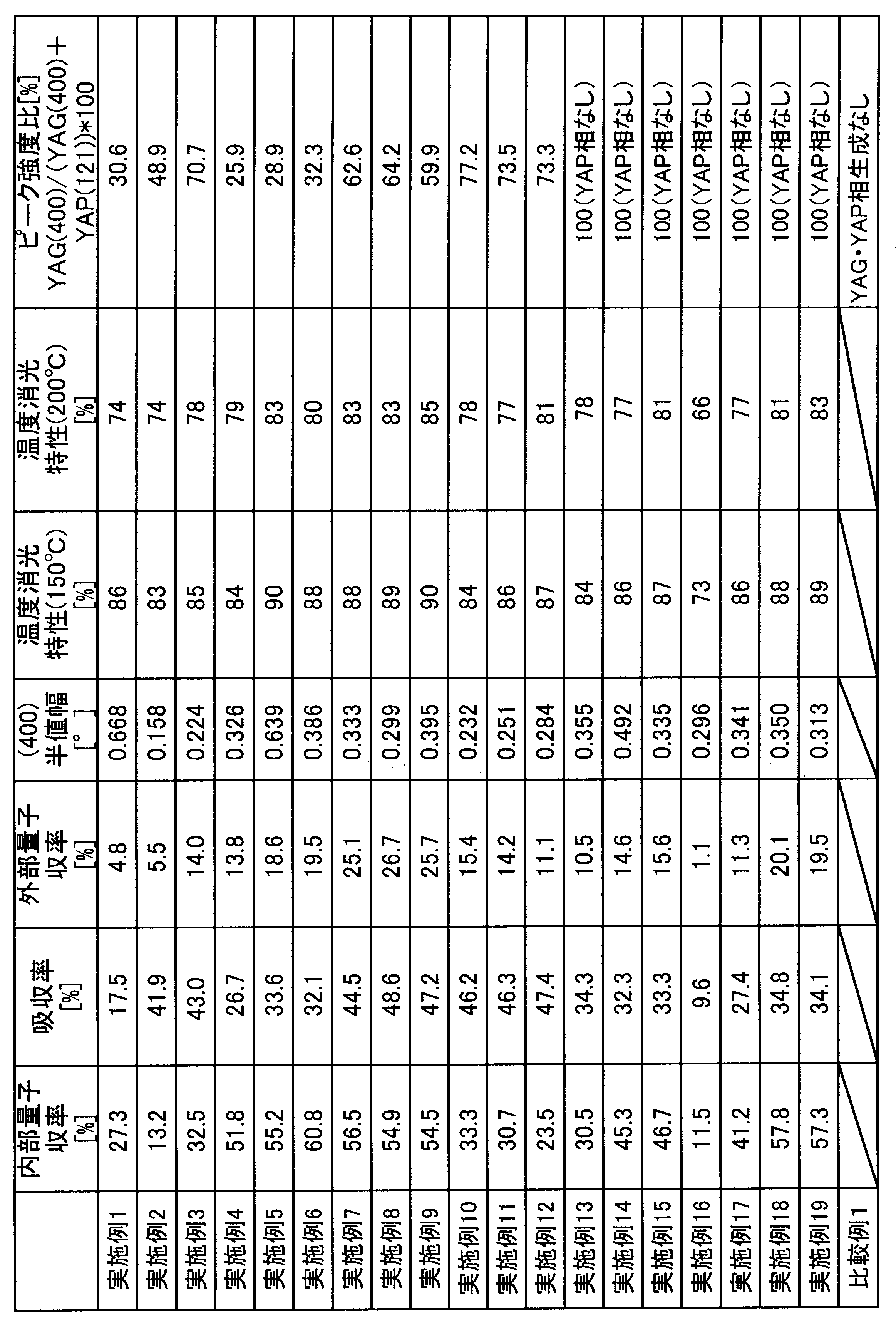
表1、2より、摩砕ミルを用いてメカノケミカル処理を行った実施例1~19では、10~30分という短時間処理で、YAG蛍光体が生成していることがわかる。また、断面SEM像のEDX分析により、YAG粒子も確認され、得られたYAG蛍光体及びYAG粒子は、無定形化(アモルファス)しておらず、結晶性の高いこともXRDの結果より確認できる。特に、実施例4~9、18、19においては内部量子収率50%を超えるYAG蛍光体が得られている。摩砕式ミルの温度は300℃程度以下と非常に低温であり、特殊な耐熱素材を必要としない。
図2は、実施例6、15、18の励起スペクトルと発光スペクトルを示したグラフである。いずれも、365~500nm程度までの励起スペクトルを持ち、540nm付近に発光スペクトルのピークを持つ黄色発光が確認されている。
図3は、実施例5~実施例9において、温度を200℃まで変化させた際の発光強度(各実施例における25℃での発光強度を100とする)を測定し、プロットしたグラフである。いずれの例においても200℃において80%以上の良好な温度消光特性を示していることがわかる。
図4は、実施例10~12のXRD解析結果を示したグラフであり、フッ化物を添加し、処理時間が短い方が比較的結晶性が高くなる傾向が見られる。
実施例20
YAG蛍光体の原料として、Y2O3(高純度化学製、体積基準のD50:0.6μm)、Al2O3(高純度化学製、体積基準のD50:0.4μm)、CeO2(高純度化学製、体積基準のD50:0.3μm)の粉末をそれぞれ、生成する蛍光体の組成がY2.97Ce0.03Al5O12となる化学量論比で、合計30g秤量し、BaF2(体積基準のD50:6μm)を6wt%添加し、図1に示した摩砕ミルに投入した。摩砕式ミルのチャンバー容器内は、1L/minにて水冷した。有底円筒型容器1はSUS304製で、その内径が80mmであり、該容器1の内周とローター2の先端翼とのクリアランス4は1mmとした。このような摩砕ミルを、回転数3000rpm、所要動力3kWで20分回転させ、メカノケミカル処理を行った。その時の摩砕式ミルの温度は210℃であった。
YAG蛍光体の原料として、Y2O3(高純度化学製、体積基準のD50:0.6μm)、Al2O3(高純度化学製、体積基準のD50:0.4μm)、CeO2(高純度化学製、体積基準のD50:0.3μm)の粉末をそれぞれ、生成する蛍光体の組成がY2.97Ce0.03Al5O12となる化学量論比で、合計30g秤量し、BaF2(体積基準のD50:6μm)を6wt%添加し、図1に示した摩砕ミルに投入した。摩砕式ミルのチャンバー容器内は、1L/minにて水冷した。有底円筒型容器1はSUS304製で、その内径が80mmであり、該容器1の内周とローター2の先端翼とのクリアランス4は1mmとした。このような摩砕ミルを、回転数3000rpm、所要動力3kWで20分回転させ、メカノケミカル処理を行った。その時の摩砕式ミルの温度は210℃であった。
得られた処理物をアルミナ製のルツボに5g投入し、黒鉛炉にて1200℃で3時間焼成した。焼成雰囲気は窒素ガス雰囲気とした。得られた蛍光体の不純物等を除去するために希塩酸中で2時間撹拌し、純水で洗った後、170℃に加熱して水分を十分に除去し、蛍光体粉末を得た。得られた蛍光体粉末の結晶構造及び発光特性を実施例1と同様の方法で測定した。その結果、YAG単一相が得られていることが確認できた。(400)面の半値幅は、0.235°であった。また、365~500nm程度までの励起スペクトルを持ち、540nm付近に発光スペクトルのピークを持つ黄色発光が確認され、25℃での内部量子収率は70.9%であり、150℃における発光強度は90%であった。
実施例21
焼成温度を1500℃にしたこと以外、実施例20と同様にしてYAG蛍光体を得た。得られた蛍光体粉末の結晶構造及び発光特性を実施例1と同様の方法で測定した。その結果、YAG単一相が得られていることが確認できた。(400)面の半値幅は、0.157°であった。また、365~500nm程度までの励起スペクトルを持ち、540nm付近に発光スペクトルのピークを持つ黄色発光が確認され、25℃での内部量子収率は80.9%であり、150℃における発光強度は95%であった。
焼成温度を1500℃にしたこと以外、実施例20と同様にしてYAG蛍光体を得た。得られた蛍光体粉末の結晶構造及び発光特性を実施例1と同様の方法で測定した。その結果、YAG単一相が得られていることが確認できた。(400)面の半値幅は、0.157°であった。また、365~500nm程度までの励起スペクトルを持ち、540nm付近に発光スペクトルのピークを持つ黄色発光が確認され、25℃での内部量子収率は80.9%であり、150℃における発光強度は95%であった。
実施例22
YAG蛍光体の原料として、Y2O3(高純度化学製、体積基準のD50:0.6μm)、Al2O3(高純度化学製、体積基準のD50:0.4μm)、CeO2(高純度化学製、体積基準のD50:0.3μm)の粉末をそれぞれ、生成する蛍光体の組成がY2.97Ce0.03Al5O12となる化学量論比で、合計30g秤量し、AlF3(体積基準のD50:7μm)を10wt%添加し、図1に示した摩砕ミルに投入した。摩砕式ミルのチャンバー容器内は、1L/minにて水冷した。有底円筒型容器1はSUS304製で、その内径が80mmであり、該容器1の内周とローター2の先端翼とのクリアランス4は1mmとした。このような摩砕ミルを、回転数3000rpm、所要動力2.5kWで15分回転させ、メカノケミカル処理を行った。その時の摩砕式ミルの温度は99.5℃であった。
得られた処理物をアルミナ製のルツボに5g投入し、黒鉛炉にて1200℃で3時間焼成した。焼成雰囲気は窒素ガス雰囲気とした。得られた蛍光体の不純物等を除去するために希塩酸中で2時間撹拌し、純水で洗った後、170℃に加熱して水分を十分に除去し、蛍光体粉末を得た。得られた蛍光体粉末の結晶構造及び発光特性を実施例1と同様の方法で測定した。その結果、YAG単一相が得られていることが確認できた。(400)面の半値幅は、0.236°であった。また、365~500nm程度までの励起スペクトルを持ち、540nm付近に発光スペクトルのピークを持つ黄色発光が確認され、25℃での内部量子収率は60.5%であり、150℃における発光強度は90%であった。
YAG蛍光体の原料として、Y2O3(高純度化学製、体積基準のD50:0.6μm)、Al2O3(高純度化学製、体積基準のD50:0.4μm)、CeO2(高純度化学製、体積基準のD50:0.3μm)の粉末をそれぞれ、生成する蛍光体の組成がY2.97Ce0.03Al5O12となる化学量論比で、合計30g秤量し、AlF3(体積基準のD50:7μm)を10wt%添加し、図1に示した摩砕ミルに投入した。摩砕式ミルのチャンバー容器内は、1L/minにて水冷した。有底円筒型容器1はSUS304製で、その内径が80mmであり、該容器1の内周とローター2の先端翼とのクリアランス4は1mmとした。このような摩砕ミルを、回転数3000rpm、所要動力2.5kWで15分回転させ、メカノケミカル処理を行った。その時の摩砕式ミルの温度は99.5℃であった。
得られた処理物をアルミナ製のルツボに5g投入し、黒鉛炉にて1200℃で3時間焼成した。焼成雰囲気は窒素ガス雰囲気とした。得られた蛍光体の不純物等を除去するために希塩酸中で2時間撹拌し、純水で洗った後、170℃に加熱して水分を十分に除去し、蛍光体粉末を得た。得られた蛍光体粉末の結晶構造及び発光特性を実施例1と同様の方法で測定した。その結果、YAG単一相が得られていることが確認できた。(400)面の半値幅は、0.236°であった。また、365~500nm程度までの励起スペクトルを持ち、540nm付近に発光スペクトルのピークを持つ黄色発光が確認され、25℃での内部量子収率は60.5%であり、150℃における発光強度は90%であった。
実施例23
焼成温度を1500℃としたこと以外、実施例22と同様にして蛍光体粉末を得た。得られた蛍光体粉末の結晶構造及び発光特性を実施例1と同様の方法で測定した。その結果、YAG単一相が得られていることが確認できた。(400)面の半値幅は、0.156°であったまた、365~500nm程度までの励起スペクトルを持ち、540nm付近に発光スペクトルのピークを持つ黄色発光が確認され、25℃での内部量子収率は70.2%であり、150℃における発光強度は94%であった。
焼成温度を1500℃としたこと以外、実施例22と同様にして蛍光体粉末を得た。得られた蛍光体粉末の結晶構造及び発光特性を実施例1と同様の方法で測定した。その結果、YAG単一相が得られていることが確認できた。(400)面の半値幅は、0.156°であったまた、365~500nm程度までの励起スペクトルを持ち、540nm付近に発光スペクトルのピークを持つ黄色発光が確認され、25℃での内部量子収率は70.2%であり、150℃における発光強度は94%であった。
実施例24
YAG蛍光体の原料として、Y2O3(高純度化学製、体積基準のD50:0.6μm)、Al2O3(高純度化学製、体積基準のD50:0.4μm)、CeO2(高純度化学製、体積基準のD50:0.3μm)の粉末をそれぞれ、生成する蛍光体の組成がY2.97Ce0.03Al5O12となる化学量論比で、合計30g秤量し、YF3(体積基準のD50:6μm)を10wt%添加し、図1に示した摩砕ミルに投入した。摩砕式ミルのチャンバー容器内は、1L/minにて水冷した。有底円筒型容器1はSUS304製で、その内径が80mmであり、該容器1の内周とローター2の先端翼とのクリアランス4は1mmとした。このような摩砕ミルを、回転数3000rpm、所要動力3kWで10分回転させ、メカノケミカル処理を行った。その時の摩砕式ミルの温度は118℃であった。
YAG蛍光体の原料として、Y2O3(高純度化学製、体積基準のD50:0.6μm)、Al2O3(高純度化学製、体積基準のD50:0.4μm)、CeO2(高純度化学製、体積基準のD50:0.3μm)の粉末をそれぞれ、生成する蛍光体の組成がY2.97Ce0.03Al5O12となる化学量論比で、合計30g秤量し、YF3(体積基準のD50:6μm)を10wt%添加し、図1に示した摩砕ミルに投入した。摩砕式ミルのチャンバー容器内は、1L/minにて水冷した。有底円筒型容器1はSUS304製で、その内径が80mmであり、該容器1の内周とローター2の先端翼とのクリアランス4は1mmとした。このような摩砕ミルを、回転数3000rpm、所要動力3kWで10分回転させ、メカノケミカル処理を行った。その時の摩砕式ミルの温度は118℃であった。
得られた処理物をアルミナ製のルツボに5g投入し、黒鉛炉にて1200℃で3時間焼成した。焼成雰囲気は窒素ガス雰囲気とした。得られた蛍光体の不純物等を除去するために希塩酸中で2時間撹拌し、純水で洗った後、170℃に加熱して水分を十分に除去し、蛍光体粉末を得た。その結果、YAG単一相が得られていることが確認できた。(400)面の半値幅は、0.234°であった。また、365~500nm程度までの励起スペクトルを持ち、540nm付近に発光スペクトルのピークを持つ黄色発光が確認され、25℃での内部量子収率は65.2%であり、150℃における発光強度は89%であった。
実施例25
焼成温度を1500℃としたこと以外、実施例24と同様にして蛍光体粉末を得た。得られた蛍光体粉末の結晶構造及び発光特性を実施例1と同様の方法で測定した。その結果、YAG単一相が得られていることが確認できた。(400)面の半値幅は、0.154°であったまた、365~500nm程度までの励起スペクトルを持ち、540nm付近に発光スペクトルのピークを持つ黄色発光が確認され、25℃での内部量子収率は72.2%であり、150℃における発光強度は95%であった。
焼成温度を1500℃としたこと以外、実施例24と同様にして蛍光体粉末を得た。得られた蛍光体粉末の結晶構造及び発光特性を実施例1と同様の方法で測定した。その結果、YAG単一相が得られていることが確認できた。(400)面の半値幅は、0.154°であったまた、365~500nm程度までの励起スペクトルを持ち、540nm付近に発光スペクトルのピークを持つ黄色発光が確認され、25℃での内部量子収率は72.2%であり、150℃における発光強度は95%であった。
本発明の無機化合物の製造方法は、従来の焼成による方法に比べて、高温設備を必要とせず、焼結後の粉砕工程や分級も必要ない。さらに、非常に短時間で合成が可能であるため、生産性も高い。また本発明で製造されるYAG蛍光体は、蛍光表示管(VFD)、フィールドエミッションディスプレイ(FED)、プラズマディスプレイパネル(PDP)、陰極線管(CRT)などの発光装置に好適に用いられる。YAG粒子は、光学材料や耐熱材料としても用いられ、産業上有用である。
1 有底円筒型容器、2 ローター、3 先端翼、4 クリアランス、5 原料粉末の混合物
Claims (14)
- 2種以上の金属酸化物粉末を含む原料粉末と、フラックスとを含む混合物を、メカノケミカル法によって処理し、前記2種以上の金属酸化物粉末を反応させる無機化合物の製造方法。
- 前記メカノケミカル法によって処理した後、この処理物を更に焼成する請求項1に記載の無機化合物の製造方法。
- 1800℃以下で焼成する請求項2に記載の無機化合物の製造方法。
- 前記反応によって得られる無機化合物が、結晶性複合金属酸化物である請求項1~3のいずれかに記載の無機化合物の製造方法。
- 前記原料粉末が、Y2O3粉末、Al2O3粉末と、Ce、Tb、Eu、Yb、Pr、Tm及びSmよりなる群から選択される少なくとも1種のドーパントの酸化物粉末を含み、
前記無機化合物がYAG蛍光体である請求項1~4のいずれかに記載の無機化合物の製造方法。 - メカノケミカル法によって前記2種以上の金属酸化物粉末を反応させる工程、酸により前記フラックスを除去する工程の両方を有する請求項1~5のいずれかに記載の無機化合物の製造方法。
- 前記フラックスが、金属水酸化物、金属酸化物及び金属ハロゲン化物よりなる群から選択される少なくとも1種である請求項1~6のいずれかに記載の無機化合物の製造方法。
- 前記金属ハロゲン化物が、金属フッ化物である請求項7に記載の無機化合物の製造方法。
- 前記金属フッ化物が、BaF2、YF3、AlF3及びSrF3よりなる群から選択される少なくとも1種である請求項8に記載の無機化合物の製造方法。
- 前記金属水酸化物が、Al(OH)3、KOH、Sr(OH)2、NaOH、Ba(OH)2、Mg(OH)2及びLiOHよりなる群から選択される少なくとも1種である請求項7~9のいずれかに記載の無機化合物の製造方法。
- 有底円筒型容器と、
この容器内周よりも小さい曲率の先端翼を有するローターとを備え、
前記先端翼と容器内周との間に所定のクリアランスを設け、
前記ローターを回転させることで、前記クリアランスで前記混合物を圧縮しながらせん断する請求項1~10のいずれかに記載の無機化合物の製造方法。 - 前記ローターの動力は、原料粉末の合計量に対して0.1kW/g以上であり、前記ローターを10分以上回転させる請求項11に記載の無機化合物の製造方法。
- 前記フラックスの添加量が、原料粉末に対して4質量%以上である請求項5~12のいずれかに記載の無機化合物の製造方法。
- メカノケミカル法で処理された物が含むYAG蛍光体の割合が、処理物全体の3質量%以上である請求項5~13のいずれかに記載の無機化合物の製造方法。
Priority Applications (1)
| Application Number | Priority Date | Filing Date | Title |
|---|---|---|---|
| JP2017526211A JP6784982B2 (ja) | 2015-07-02 | 2016-05-16 | 無機化合物の製造方法 |
Applications Claiming Priority (4)
| Application Number | Priority Date | Filing Date | Title |
|---|---|---|---|
| JP2015133594 | 2015-07-02 | ||
| JP2015-133594 | 2015-07-02 | ||
| JP2015190173 | 2015-09-28 | ||
| JP2015-190173 | 2015-09-28 |
Publications (1)
| Publication Number | Publication Date |
|---|---|
| WO2017002467A1 true WO2017002467A1 (ja) | 2017-01-05 |
Family
ID=57608270
Family Applications (1)
| Application Number | Title | Priority Date | Filing Date |
|---|---|---|---|
| PCT/JP2016/064420 Ceased WO2017002467A1 (ja) | 2015-07-02 | 2016-05-16 | 無機化合物の製造方法 |
Country Status (2)
| Country | Link |
|---|---|
| JP (1) | JP6784982B2 (ja) |
| WO (1) | WO2017002467A1 (ja) |
Cited By (9)
| Publication number | Priority date | Publication date | Assignee | Title |
|---|---|---|---|---|
| JP2018053227A (ja) * | 2015-12-03 | 2018-04-05 | セイコーエプソン株式会社 | 蛍光体、波長変換素子、光源装置およびプロジェクター |
| US9952491B2 (en) | 2015-12-03 | 2018-04-24 | Seiko Epson Corporation | Phosphor, wavelength conversion element, light source device, and projector |
| JP2018156835A (ja) * | 2017-03-17 | 2018-10-04 | 古河機械金属株式会社 | 無機材料の製造方法 |
| WO2020026971A1 (ja) * | 2018-08-03 | 2020-02-06 | 株式会社カネカ | ガーネット型複合金属酸化物及びその製造方法 |
| JP2020183576A (ja) * | 2019-04-26 | 2020-11-12 | 日本イットリウム株式会社 | 成膜用又は焼結用粉末 |
| JPWO2021157566A1 (ja) * | 2020-02-05 | 2021-08-12 | ||
| CN115003630A (zh) * | 2020-02-07 | 2022-09-02 | 加利福尼亚大学董事会 | 用于锂离子电池的具有减少短程有序的阳离子无序岩盐型高熵阴极 |
| US11973184B2 (en) | 2018-08-03 | 2024-04-30 | Kaneka Corporation | Garnet-type composite metal oxide and method for producing same |
| US12084355B2 (en) | 2018-08-30 | 2024-09-10 | Kaneka Corporation | Garnet-type composite metal oxide particle and method for producing same, and compression-molded product of garnet-type composite metal oxide |
Citations (7)
| Publication number | Priority date | Publication date | Assignee | Title |
|---|---|---|---|---|
| JPH0952773A (ja) * | 1995-08-09 | 1997-02-25 | Nara Kikai Seisakusho:Kk | 複合酸化物セラミックスの製造方法 |
| JPH09255893A (ja) * | 1996-03-26 | 1997-09-30 | Nippon Fueroo Kk | 合成複合酸化物の製造法 |
| JP2000044235A (ja) * | 1998-07-29 | 2000-02-15 | Natl Res Inst For Metals | イットリウム・アルミニウム複合酸化物の製造方法 |
| JP2001240858A (ja) * | 2000-02-29 | 2001-09-04 | Nemoto & Co Ltd | 蛍光体 |
| JP2002515393A (ja) * | 1998-05-15 | 2002-05-28 | アドバンスド ナノ テクノロジーズ プロプライエタリー リミテッド | 超微粒粉末の製造方法 |
| JP2014002857A (ja) * | 2012-06-15 | 2014-01-09 | Toyota Motor Corp | 活物質材料、電池、および活物質材料の製造方法 |
| JP2014019860A (ja) * | 2012-07-24 | 2014-02-03 | Shin Etsu Chem Co Ltd | 蛍光体前駆体の製造方法、蛍光体の製造方法及び波長変換部品 |
-
2016
- 2016-05-16 JP JP2017526211A patent/JP6784982B2/ja active Active
- 2016-05-16 WO PCT/JP2016/064420 patent/WO2017002467A1/ja not_active Ceased
Patent Citations (7)
| Publication number | Priority date | Publication date | Assignee | Title |
|---|---|---|---|---|
| JPH0952773A (ja) * | 1995-08-09 | 1997-02-25 | Nara Kikai Seisakusho:Kk | 複合酸化物セラミックスの製造方法 |
| JPH09255893A (ja) * | 1996-03-26 | 1997-09-30 | Nippon Fueroo Kk | 合成複合酸化物の製造法 |
| JP2002515393A (ja) * | 1998-05-15 | 2002-05-28 | アドバンスド ナノ テクノロジーズ プロプライエタリー リミテッド | 超微粒粉末の製造方法 |
| JP2000044235A (ja) * | 1998-07-29 | 2000-02-15 | Natl Res Inst For Metals | イットリウム・アルミニウム複合酸化物の製造方法 |
| JP2001240858A (ja) * | 2000-02-29 | 2001-09-04 | Nemoto & Co Ltd | 蛍光体 |
| JP2014002857A (ja) * | 2012-06-15 | 2014-01-09 | Toyota Motor Corp | 活物質材料、電池、および活物質材料の製造方法 |
| JP2014019860A (ja) * | 2012-07-24 | 2014-02-03 | Shin Etsu Chem Co Ltd | 蛍光体前駆体の製造方法、蛍光体の製造方法及び波長変換部品 |
Non-Patent Citations (1)
| Title |
|---|
| ZHANG, QIWU ET AL.: "Mechanochemical solid reaction of yttrium oxide with alumina leading to the synthesis of yttrium aluminum garnet", POWDER TECHNOLOGY, vol. 129, no. 1-3, 2003, pages 86 - 91, XP009055067 * |
Cited By (17)
| Publication number | Priority date | Publication date | Assignee | Title |
|---|---|---|---|---|
| JP2018053227A (ja) * | 2015-12-03 | 2018-04-05 | セイコーエプソン株式会社 | 蛍光体、波長変換素子、光源装置およびプロジェクター |
| US9952491B2 (en) | 2015-12-03 | 2018-04-24 | Seiko Epson Corporation | Phosphor, wavelength conversion element, light source device, and projector |
| JP2018156835A (ja) * | 2017-03-17 | 2018-10-04 | 古河機械金属株式会社 | 無機材料の製造方法 |
| US11973184B2 (en) | 2018-08-03 | 2024-04-30 | Kaneka Corporation | Garnet-type composite metal oxide and method for producing same |
| CN112533872B (zh) * | 2018-08-03 | 2023-04-04 | 株式会社钟化 | 石榴石型复合金属氧化物及其制造方法 |
| CN112533872A (zh) * | 2018-08-03 | 2021-03-19 | 株式会社钟化 | 石榴石型复合金属氧化物及其制造方法 |
| WO2020026971A1 (ja) * | 2018-08-03 | 2020-02-06 | 株式会社カネカ | ガーネット型複合金属酸化物及びその製造方法 |
| JP7389436B2 (ja) | 2018-08-03 | 2023-11-30 | 株式会社カネカ | ガーネット型複合金属酸化物及びその製造方法、並びに二次電池用固体電解質材料 |
| JPWO2020026971A1 (ja) * | 2018-08-03 | 2021-08-19 | 株式会社カネカ | ガーネット型複合金属酸化物及びその製造方法 |
| US12084355B2 (en) | 2018-08-30 | 2024-09-10 | Kaneka Corporation | Garnet-type composite metal oxide particle and method for producing same, and compression-molded product of garnet-type composite metal oxide |
| JP2020183576A (ja) * | 2019-04-26 | 2020-11-12 | 日本イットリウム株式会社 | 成膜用又は焼結用粉末 |
| WO2021157566A1 (ja) * | 2020-02-05 | 2021-08-12 | 株式会社カネカ | 固体電解質 |
| JPWO2021157566A1 (ja) * | 2020-02-05 | 2021-08-12 | ||
| JP7687566B2 (ja) | 2020-02-05 | 2025-06-03 | 株式会社カネカ | 固体電解質及びその製造方法 |
| US12347826B2 (en) | 2020-02-05 | 2025-07-01 | Kaneka Corporation | Solid electrolyte |
| CN115003630A (zh) * | 2020-02-07 | 2022-09-02 | 加利福尼亚大学董事会 | 用于锂离子电池的具有减少短程有序的阳离子无序岩盐型高熵阴极 |
| US12597608B2 (en) | 2020-02-07 | 2026-04-07 | The Regents Of The University Of California | Cation-disordered rocksalt type high entropy cathode with reduced short-range order for Li-ion batteries |
Also Published As
| Publication number | Publication date |
|---|---|
| JP6784982B2 (ja) | 2020-11-18 |
| JPWO2017002467A1 (ja) | 2018-04-12 |
Similar Documents
| Publication | Publication Date | Title |
|---|---|---|
| JP6784982B2 (ja) | 無機化合物の製造方法 | |
| Zhou et al. | Mn 2+ and Mn 4+ red phosphors: synthesis, luminescence and applications in WLEDs. A review | |
| KR101037616B1 (ko) | 형광체와 그 제조방법, 조명기구, 및 화상표시장치 | |
| JP5224439B2 (ja) | 蛍光体、およびそれを用いた発光器具 | |
| JP5206941B2 (ja) | 蛍光体とその製造方法および発光器具 | |
| JP5234781B2 (ja) | 蛍光体とその製造方法および発光器具 | |
| Du et al. | Synthesis and luminescent properties of red-emitting Eu3+-activated Ca0. 5Sr0. 5MoO4 phosphors | |
| JP5978980B2 (ja) | イットリウムセリウムアルミニウムガーネット蛍光体の製造方法 | |
| Xi et al. | Abnormal site occupancy and high performance in warm WLEDs of a novel red phosphor, NaHF 2: Mn 4+, synthesized at room temperature | |
| JP5854051B2 (ja) | 酸窒化物蛍光体粉末及びその製造方法 | |
| TWI613841B (zh) | 波長轉換構件及使用其之發光裝置 | |
| Yang et al. | A novel phosphor of Eu3+-activated Na3GaF6: Synthesis, structure, and luminescence properties | |
| TWI538983B (zh) | Yttrium cerium aluminum garnet phosphors and light emitting devices | |
| JP2016216711A (ja) | 蛍光体、その製造方法、照明器具および画像表示装置 | |
| WO2016186058A1 (ja) | 発光器具および画像表示装置 | |
| JP2016176007A (ja) | Yag蛍光体用複合粒子、yag蛍光体及びその製造方法 | |
| JP2011052099A (ja) | 窒化物蛍光体の製造方法 | |
| JP5071714B2 (ja) | 蛍光体、その製造方法およびそれを用いた発光器具 | |
| Wang et al. | Influence of different aid-sintering additives on the green-emitting β-SiAlON: Eu 2+ phosphors | |
| WO2014006755A1 (ja) | シリケート蛍光体およびその製造方法 | |
| JP7400378B2 (ja) | 発光装置、照明装置、画像表示装置および窒化物蛍光体 | |
| JP7144002B2 (ja) | 蛍光体及びこれを用いた蛍光体組成物、並びにこれらを用いた発光装置、照明装置及び画像表示装置 | |
| CN101790572A (zh) | 钇和稀土元素的混合氧化物的制备方法 | |
| JP6959601B2 (ja) | 蛍光体の製造方法 | |
| KR101226253B1 (ko) | 산질화물 형광체의 제조방법과 이에 따라 제조된 산질화물 형광체 |
Legal Events
| Date | Code | Title | Description |
|---|---|---|---|
| 121 | Ep: the epo has been informed by wipo that ep was designated in this application |
Ref document number: 16817576 Country of ref document: EP Kind code of ref document: A1 |
|
| ENP | Entry into the national phase |
Ref document number: 2017526211 Country of ref document: JP Kind code of ref document: A |
|
| NENP | Non-entry into the national phase |
Ref country code: DE |
|
| 122 | Ep: pct application non-entry in european phase |
Ref document number: 16817576 Country of ref document: EP Kind code of ref document: A1 |