WO2017002233A1 - 煤吹装置 - Google Patents
煤吹装置 Download PDFInfo
- Publication number
- WO2017002233A1 WO2017002233A1 PCT/JP2015/069007 JP2015069007W WO2017002233A1 WO 2017002233 A1 WO2017002233 A1 WO 2017002233A1 JP 2015069007 W JP2015069007 W JP 2015069007W WO 2017002233 A1 WO2017002233 A1 WO 2017002233A1
- Authority
- WO
- WIPO (PCT)
- Prior art keywords
- lance tube
- outer diameter
- tube
- lance
- end side
- Prior art date
Links
Images


Classifications
-
- F—MECHANICAL ENGINEERING; LIGHTING; HEATING; WEAPONS; BLASTING
- F23—COMBUSTION APPARATUS; COMBUSTION PROCESSES
- F23J—REMOVAL OR TREATMENT OF COMBUSTION PRODUCTS OR COMBUSTION RESIDUES; FLUES
- F23J3/00—Removing solid residues from passages or chambers beyond the fire, e.g. from flues by soot blowers
-
- F—MECHANICAL ENGINEERING; LIGHTING; HEATING; WEAPONS; BLASTING
- F22—STEAM GENERATION
- F22B—METHODS OF STEAM GENERATION; STEAM BOILERS
- F22B37/00—Component parts or details of steam boilers
- F22B37/02—Component parts or details of steam boilers applicable to more than one kind or type of steam boiler
- F22B37/48—Devices for removing water, salt, or sludge from boilers; Arrangements of cleaning apparatus in boilers; Combinations thereof with boilers
- F22B37/54—De-sludging or blow-down devices
-
- F—MECHANICAL ENGINEERING; LIGHTING; HEATING; WEAPONS; BLASTING
- F28—HEAT EXCHANGE IN GENERAL
- F28G—CLEANING OF INTERNAL OR EXTERNAL SURFACES OF HEAT-EXCHANGE OR HEAT-TRANSFER CONDUITS, e.g. WATER TUBES OR BOILERS
- F28G1/00—Non-rotary, e.g. reciprocated, appliances
- F28G1/16—Non-rotary, e.g. reciprocated, appliances using jets of fluid for removing debris
Definitions
- the present invention relates to a soot blower that removes deposits attached to a boiler tube of a boiler, for example.
- a soot blowing device one having a structure in which a lance tube having an injection nozzle at its tip is advanced and retracted while rotating is known.
- the travel of the lance tube (advance / retreat range) is appropriately set according to the furnace width of the boiler. Since the travel of the lance tube is, for example, about 10 m, when the lance tube protrudes to the maximum travel, a large bending stress is applied to the proximal end side of the lance tube.
- Patent Document 1 in order to reduce the bending stress applied to the base end side of the lance tube, the base end side thickness of the lance tube having a constant outer diameter is increased, and the tip end side plate thickness is reduced. The technology to do is described.
- An object of the present invention is to provide a soot blowing device that can suppress drooping of the tip of the lance tube by the lance tube itself in the soot blowing device that advances and retracts the lance tube.
- the soot blowing device includes a cylindrical lance tube provided with an injection nozzle for injecting an injection medium at the tip, and the lance tube inserted into the inner peripheral side of the lance tube.
- An injection medium supply pipe for supplying an injection medium to the tube; a drive device for moving the lance tube in a direction along the axial direction of the lance tube; and the lance tube capable of moving forward and backward in the axial direction from below the lance tube.
- a support roller for supporting the lance tube wherein the lance tube is formed in a part in a direction along the axial direction, and at least a portion of the lance tube supported by the support roller in the circumferential direction is from the distal end side to the proximal end side of the lance tube. It has the taper part which an outer diameter expands gradually as it goes to.
- the tip side of the lance tube is lifted according to the enlargement of the taper portion.
- the lance tube itself can suppress the sag of the lance tube tip due to the deflection of the lance tube.
- the lance tube may have a cylindrical shape, and the tapered portion may gradually increase in outer diameter over the entire circumferential direction.
- the lance tube is provided on the distal end side and has a small diameter portion whose outer diameter forms a first outer diameter, and is provided on the proximal end side and has an outer diameter smaller than the first outer diameter.
- the outer diameter of the connecting portion between the large diameter portion forming the second outer diameter of the large diameter and the small diameter portion is the first outer diameter
- the outer diameter of the connecting portion with the large diameter portion is the second outer diameter.
- a taper portion having an outer diameter.
- the bending stress applied to the proximal end side of the lance tube can be reduced by improving the rigidity of the proximal end side of the lance tube rather than the distal end side.
- the above-described soot blowing device may include a seal member that seals between an outer peripheral surface of the ejection medium supply pipe and an inner peripheral surface of the lance tube, and the lance tube may have a constant inner diameter.
- the thickness of the base end side of the lance tube can be increased without reducing the gap between the outer peripheral surface of the ejection medium supply pipe and the inner peripheral surface of the lance tube.
- the interference between the inner peripheral surface of the lance tube and the injection medium supply pipe can be suppressed and the inner peripheral surface of the lance tube can be prevented from being damaged, and the seal between the injection medium supply pipe and the lance tube can be prevented.
- the lance tube itself can suppress the sagging of the tip of the lance tube due to the deflection of the lance tube.
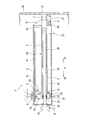
- the soot blower 1 of this embodiment is provided in the wall part 50 of the waste heat recovery boiler which recovers heat from waste gas, for example in a power plant.
- the soot blowing device 1 is a device that removes deposits that adhere to the surface (heat transfer surface) of the boiler tube of the exhaust heat recovery boiler and hinder heat exchange.
- the object to be removed by the soot blower 1 of the present embodiment is not limited to a boiler such as an exhaust heat recovery boiler.
- the soot blowing apparatus 1 of this embodiment is applicable to various heat exchangers, such as an air preheater and a economizer.
- the soot blower 1 is coaxial with the injection medium supply pipe 3 on the outer peripheral side of the housing 2, the tubular injection medium supply pipe 3 (feed pipe) fixed in the housing 2, and the injection medium supply pipe 3.
- the lance tube 4 is supplied with an injection medium G such as steam via the injection medium supply pipe 3.
- the ejection medium G is ejected from an ejection nozzle 7 provided at the tip of the lance tube 4.
- the lance tube 4 rotates around its axis and advances and retreats inside the boiler.
- the wall part 50 of the exhaust heat recovery boiler extends in the vertical direction, and the axial directions of the ejection medium supply pipe 3 and the lance tube 4 are orthogonal to the wall part 50. That is, the ejection medium supply pipe 3 and the lance tube 4 extend in the horizontal direction.
- the direction in which the central axis of the ejection medium supply pipe 3 extends and the direction in which the lance tube 4 advances and retreats is referred to as an advancing / retreating direction X.
- the right side in FIG. 1 is the forward / backward direction front side X1
- the left side in FIG. 1 is the forward / backward direction rear side X2.
- the lance tube 4 has an injection nozzle 7 at the tip (end of the forward and backward direction X1).
- the lance tube 4 is inserted into the boiler through a boiler through hole 51 formed in the wall portion 50 from an injection nozzle 7 provided at the tip of the lance tube 4.
- the housing 2 has a rectangular tube shape that is long in the horizontal direction (advancing / retreating direction X).
- the ejection medium supply pipe 3 and the lance tube 4 are arranged along the longitudinal direction of the housing 2.
- the housing 2 is fixed to a predetermined structure of the plant via, for example, a first bracket 8 provided on the upper surface of the upper wall 18 of the housing 2.
- a head valve 10 (supply valve) is provided on the second side wall 25 that is the side wall on the rear side X2 in the forward / backward direction of the housing 2.
- An ejection medium G such as steam is supplied to the head valve 10 via a pipe (not shown).
- the ejection medium supply pipe 3 is a tubular member that is inserted into the inner peripheral side of the lance tube 4 and supplies the ejection medium G supplied to the head valve 10 to the lance tube 4.
- An end of the ejection medium supply pipe 3 on the rear side X2 in the forward / backward direction is fixed to the inner surface of the second side wall 25 of the housing 2.
- the inside of the ejection medium supply pipe 3 communicates with the head valve 10. That is, the ejection medium G supplied to the head valve 10 is introduced into the ejection medium supply pipe 3.
- the lance tube 4 has a cylindrical shape and is arranged coaxially with the ejection medium supply pipe 3 on the outer peripheral side of the ejection medium supply pipe 3.
- An injection nozzle 7 is formed at the end of the lance tube 4 on the front side X1 in the forward / backward direction.
- a flange 12 that protrudes radially from the outer peripheral surface of the lance tube 4 is formed at the end of the lance tube 4 on the rear side X2 in the forward and backward direction.
- the distal end side of the lance tube 4 protrudes to the outside of the housing 2 through the housing through hole 13 and is inserted into the boiler through the boiler through hole 51.
- the driving device 5 includes a traveling carriage 14 attached to the flange 12 of the lance tube 4, a motor 15 attached to the traveling carriage 14, a pinion 16 rotated by the driving force of the motor 15, and a pinion 16 And a rack 17 fixed to the inner surface (lower surface) of the upper wall 18 of the housing 2.
- the traveling carriage 14 has a shape that holds the flange 12 of the lance tube 4 (end portion on the rear side X2 in the forward / backward direction) and covers the outer periphery of the ejection medium supply pipe 3.
- a gland packing 20 is provided as a seal member that seals between the inner circumferential surface of the traveling carriage 14 and the outer circumferential surface of the ejection medium supply pipe 3. ing. That is, the traveling carriage 14 can slide on the ejection medium supply pipe 3 via the gland packing 20.
- a rotating mechanism 21 is provided on the front side X1 of the traveling carriage 14 in the forward / backward direction.
- the flange 12 of the lance tube 4 is connected to the rotation mechanism 21. That is, the rear end side of the lance tube 4 is rotatably attached to the traveling carriage 14.
- a guide roller 22 that travels on a guide rail (not shown) provided along the longitudinal direction of the housing 2 is attached to the traveling carriage 14.
- a limit switch 23 is attached to the housing 2.
- the limit switch 23 is attached at a position where the position of the guide roller 22 can be detected.
- the limit switches 23 are respectively installed at the end of the housing 2 in the forward / backward direction forward side X1 and the end of the forward / backward direction backward side X2.
- the limit switch 23 is used to control the moving range of the lance tube 4 in the forward / backward direction.
- the traveling carriage 14 moves in the advancing / retreating direction X as the pinion 16 travels on the rack 17 that meshes with the pinion 16. That is, the lance tube 4 integrated with the traveling carriage 14 is moved in the forward / backward direction X by the power of the motor 15.
- the support roller 6 has a cylindrical shape and supports the lance tube 4 from below.
- the support roller 6 is attached to the first side wall 24 of the housing 2.
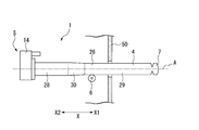
- the support roller 6 supports the distal end side of the lance tube 4 when the lance tube 4 is disposed in the retracted position as shown in FIG. 1 (minimum travel), and the lance tube 4 protrudes as shown in FIG.
- the base end side of the lance tube 4 is supported. That is, the support roller 6 always supports the lance tube 4 from below when the lance tube 4 is advanced and retracted.
- the support roller 6 is disposed at a position where the central axis of the lance tube 4 is along the horizontal direction when the lance tube 4 is in the retracted position shown in FIG.
- One support roller 6 may support the lance tube 4, or a plurality of support rollers 6 may support the lance tube 4.
- the support roller is not limited to the structure described above, and may be any structure that can support the lance tube 4 so as to be able to advance and retract. For example, it is good also as a structure which supports the lance tube 4 in the inner peripheral side of a ring-shaped roller.
- the lance tube 4 of the present embodiment includes a cylindrical lance tube main body 26, a flange 12 provided on the rear side X ⁇ b> 2 (base end side) of the lance tube main body 26, and advancing / retreating. And a head portion 27 provided on the front side X1 (front end side).
- the injection nozzle 7 is provided in the head portion 27.
- a plurality of injection nozzles 7 are provided on the outer peripheral surface of the head portion 27.
- the diameter and shape of the injection nozzle 7 can be selected according to the object to be removed.
- the lance tube main body 26 has a large diameter portion 28 on the rear side X2 in the forward / backward direction, a small diameter portion 29 on the front side X1 in the forward / backward direction, and a tapered portion 30 connecting the large diameter portion 28 and the small diameter portion 29.
- the taper portion 30 is formed in a part in the axial direction.
- the large diameter part 28, the taper part 30, the small diameter part 29, and the head part 27 are joined by welding.
- the large diameter part 28, the taper part 30, and the small diameter part 29 have the same inner diameter D1. That is, the inner diameter D1 of the lance tube body 26 is the same over the entire axial direction.
- the large diameter portion 28 can be formed of Cr / Mo / V steel.
- the outer diameter D2 (second outer diameter) of the large diameter portion 28 can be set to 105 mm, for example.
- the wall thickness of the large diameter part 28 can be 7.5 mm, for example.
- the small-diameter portion 29 can be formed of SUS321, which is stainless steel in which titanium is added to stainless steel such as SUS304 to enhance intergranular corrosion resistance.
- the outer diameter D3 (first outer diameter) of the small diameter portion 29 is smaller than the outer diameter D2 of the large diameter portion 28, and can be, for example, 102 mm.
- the thickness of the small diameter part 29 can be 6 mm, for example, and the thickness of the large diameter part 28 is formed thicker than the thickness of the small diameter part 29.
- the tapered portion 30 can be formed of SUS321.
- the outer diameter of the taper portion 30 (the diameter of the outer peripheral surface 30a) gradually increases from the connection portion C1 with the small diameter portion 29 toward the connection portion C2 with the large diameter portion 28 over the entire circumferential direction.
- the outer diameter of the tapered portion 30 on the tip side (the outer diameter of the connecting portion C1 with the small diameter portion 29) is the same as the outer diameter D3 of the small diameter portion 29, and can be, for example, 102 mm.
- the outer diameter on the proximal end side of the taper portion 30 (the outer diameter of the connection portion C2 with the large diameter portion 28) is the same as the outer diameter D2 of the large diameter portion 28, and can be, for example, 105 mm.
- the outer peripheral surface 30a of the taper portion 30 has a gradually increasing diameter toward the rear side X2 in the advance / retreat direction.
- the outer diameter D2 of the large diameter portion 28 is larger than the outer diameter D3 of the small diameter portion 29, and the outer periphery of the tapered portion 30 If the diameter gradually increases as the surface 30a moves toward the rear side X2 in the forward / backward direction, the surface 30a can be appropriately changed according to the specifications of the installed boiler.
- the head portion 27 can be formed of SCH 13 that is heat-resistant cast steel.
- the material forming the large diameter portion 28, the tapered portion 30, the small diameter portion 29, and the head portion 27 constituting the lance tube 4 is not limited to the above-described materials. If it can fulfill the function as a tube, it can be changed as appropriate.
- the support roller 6 is disposed at a position where the central axis A of the lance tube 4 is horizontal when the small diameter portion 29 of the lance tube 4 is supported.
- the central axis A of the lance tube 4 is Tilt to be upward. That is, when the outer diameter of the portion supported by the support roller 6 is increased, the height of the distal end side of the lance tube 4 is higher than the proximal end side of the lance tube 4. The height of the proximal end side of the lance tube 4 is not changed by the inclination of the lance tube 4.
- the tip of the lance tube 4 is lifted according to the enlargement of the tapered portion 30.
- the lance tube itself can suppress the sagging of the tip of the lance tube 4 due to the deflection of the lance tube 4.
- the thickness of the large diameter portion 28 on the proximal end side of the lance tube 4 is formed thicker than the thickness of the small diameter portion 29 on the distal end side of the lance tube 4. The side rigidity is improved. Thereby, the bending stress concerning the base end side of the lance tube 4 can be reduced.
- the base end side of the lance tube 4 is not narrowed without narrowing the gap between the outer peripheral surface of the ejection medium supply pipe 3 and the inner peripheral surface of the lance tube 4.
- the base end side plate In order to reduce bending stress on the base end side, in the case of a conventional type lance tube in which the base end side thickness of the lance tube having a constant outer diameter is increased on the inner peripheral side, the base end side plate In some cases, the ridge line between the thickened portion and the tapered portion where the thickness gradually decreases toward the tip side interferes with the outer peripheral surface of the ejection medium supply pipe.
- the lance tube 4 of the present embodiment can prevent the ejection medium supply pipe 3 from being damaged due to the above interference, and can improve the sealing performance between the ejection medium supply pipe 3 and the lance tube 4.
- the lance tube body 26 does not need to be cylindrical. That is, in the case of a configuration in which the lance tube 4 is advanced and retracted without providing the rotation mechanism 21, the lance tube 4 may have a cylindrical shape such as an octagonal cross section.
- the tapered portion 30 may be formed so that at least a portion of the lance tube 4 supported by the circumferential direction of the lance tube 4 gradually increases in outer diameter. That is, the tapered portion 30 may not be formed over the entire circumferential direction of the lance tube 4.
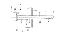
- the lance tube 4B of the soot blower of this embodiment has a flange 12 part, a lance tube main body 26B, and a head part 27.
- the outer diameter of the lance tube main body 26B is the tip. It is expanding at a certain ratio from the base to the base.
- the lance tube 4B of the present embodiment has no outer diameter portion and no outer diameter portion, and has an outer peripheral surface that continuously expands from the distal end to the proximal end.
- the ratio between the horizontal direction and the vertical direction is changed to make the thickness of the lance tube 4 ⁇ / b> B easier to understand.
- the tip of the lance tube 4B is smoothly lifted as the lance tube 4B moves toward the front side X1 in the advance / retreat direction. Thereby, the shake of the lance tube 4 when the edge part of the taper part 30 of 1st embodiment passes the support roller 6 can be suppressed.
- the drive device 5 moves the lance tube 4 forward and backward using a rack and pinion mechanism, but the present invention is not limited to this.
- the lance tube 4 may be advanced and retracted using a chain / sprocket mechanism.
- the inner diameter of the lance tube 4 does not have to be the same from the distal end to the proximal end, and the thickness near the proximal end may be increased to increase the strength.
Landscapes
- Engineering & Computer Science (AREA)
- Mechanical Engineering (AREA)
- General Engineering & Computer Science (AREA)
- Chemical & Material Sciences (AREA)
- Combustion & Propulsion (AREA)
- Physics & Mathematics (AREA)
- Thermal Sciences (AREA)
- Incineration Of Waste (AREA)
Abstract
Description
特許文献1には、ランスチューブの基端側にかかる曲げ応力を軽減するために、一定の外径を有するランスチューブの基端側の板厚を厚くするとともに、先端側の板厚を薄く形成する技術が記載されている。
以下、本発明の第一実施形態の煤吹装置(スーツブロワ)について図面を参照して詳細に説明する。
図1に示すように、本実施形態の煤吹装置1は、例えば、発電プラントにおいて、排ガスより熱回収を行う排熱回収ボイラの壁部50に設けられている。煤吹装置1は、排熱回収ボイラのボイラチューブの表面(伝熱表面)に付着して熱交換の妨げになる付着物を除去する装置である。
本実施形態の煤吹装置1によって除煤される対象は、排熱回収ボイラ等のボイラに限ることはない。本実施形態の煤吹装置1は、例えば、空気予熱器、節炭器等の各種熱交換器に適用可能である。
以下、噴射媒体供給管3の中心軸が延びている方向であって、ランスチューブ4が進退する方向を進退方向Xとする。また、図1における右側を進退方向前方側X1とし、図1における左側を進退方向後方側X2とする。
噴射媒体供給管3は、ランスチューブ4の内周側に挿入されて、ヘッドバルブ10に供給される噴射媒体Gをランスチューブ4に供給する管状をなす部材である。噴射媒体供給管3の進退方向後方側X2の端部は、ハウジング2の第二側壁25の内面に固定されている。噴射媒体供給管3の内部は、ヘッドバルブ10に連通している。即ち、ヘッドバルブ10に供給される噴射媒体Gは、噴射媒体供給管3に導入される。
トラベリングキャレッジ14には、ハウジング2の長手方向に沿って設けられているガイドレール(図示せず)上を走行するガイドローラ22が取り付けられている。
支持ローラ6は、ランスチューブ4が図1に示す格納位置にある場合に、ランスチューブ4の中心軸が水平方向に沿うような位置に配置されている。支持ローラ6は、1個でランスチューブ4を支持してもよいし、複数でランスチューブ4を支持してもよい。
支持ローラとしては上記した構造に限らず、ランスチューブ4を進退動作自在に支持できる構造であればよい。例えば、リング状のローラの内周側でランスチューブ4を支持する構造としてもよい。
図2に示すように、本実施形態のランスチューブ4は、円筒形状のランスチューブ本体26と、ランスチューブ本体26の進退方向後方側X2(基端側)に設けられているフランジ12と、進退方向前方側X1(先端側)に設けられているヘッド部27と、を有している。
大径部28、テーパ部30、小径部29、及びヘッド部27は、溶接によって接合されている。
大径部28、テーパ部30、及び小径部29の内径D1は、同一である。即ち、ランスチューブ本体26の内径D1は、軸方向全体に亘って同一である。
小径部29は、SUS304等のステンレス鋼にチタンを添加して耐粒界腐食性を高めたステンレス鋼であるSUS321によって形成することができる。小径部29の外径D3(第一の外径)は、大径部28の外径D2よりも小径であり、例えば、102mmとすることができる。
また、小径部29の肉厚は、例えば、6mmとすることができ、小径部29の肉厚よりも大径部28の肉厚が厚く形成されている。
テーパ部30の先端側の外径(小径部29との接続部C1の外径)は、小径部29の外径D3と同一であり、例えば、102mmとすることができる。テーパ部30の基端側の外径(大径部28との接続部C2の外径)は、大径部28の外径D2と同一であり、例えば、105mmとすることができる。即ち、テーパ部30の外周面30aは、進退方向後方側X2に向かうに従って漸次直径が大きくなっている。
以上、ランスチューブ4の寸法について記載したが、上記した例は一例であり、小径部29の外径D3よりも大径部28の外径D2の方が大径であり、テーパ部30の外周面30aが進退方向後方側X2に向かうに従って漸次直径が大きくなっていれば、設置されるボイラの仕様等に応じて適宜変更することができる。
以上、ランスチューブ4の詳細について説明したが、ランスチューブ4構成する大径部28、テーパ部30、小径部29、及びヘッド部27を形成する材料は、上記したものに限ることはなく、ランスチューブとしての機能を果たすことができれば、適宜変更することができる。
図3に示すように、支持ローラ6は、ランスチューブ4の小径部29を支持している場合に、ランスチューブ4の中心軸Aが水平となる位置に配置されている。
基端側にかかる曲げ応力を軽減するために、一定の外径を有するランスチューブの基端側の板厚を内周側に厚く形成した、従来型のランスチューブの場合、基端側の板厚を厚く形成した部位と、先端側に向かって徐々に肉厚が薄くなるテーパ部との間の稜線と、噴射媒体供給管の外周面とが干渉することがあった。本実施形態のランスチューブ4は、上記干渉により噴射媒体供給管3に傷が付くことを防止でき、噴射媒体供給管3とランスチューブ4との間のシール性を向上させることができる。
この場合、テーパ部30は、ランスチューブ4の周方向の少なくとも支持ローラ6で支持される部位が、漸次外径が拡大するように形成すればよい。即ち、ランスチューブ4の周方向全体に亘ってテーパ部30を形成しなくてもよい。
以下、本発明の第二実施形態の煤吹装置を図面に基づいて説明する。なお、本実施形態では、上述した第一実施形態との相違点を中心に述べ、同様の部分についてはその説明を省略する。
図5に示すように、本実施形態の煤吹装置のランスチューブ4Bは、フランジ12部と、ランスチューブ本体26Bと、ヘッド部27と、を有し、ランスチューブ本体26Bの外径は、先端から基端まで一定の比率で拡大している。即ち、本実施形態のランスチューブ4Bは、大径部と小径部がなく、先端から基端まで連続して拡径する外周面を有している。
なお、図5においては、ランスチューブ4Bの肉厚をわかりやすくするために、横方向と縦方向の比率を変更している。
例えば、上記各実施形態においては、駆動装置5は、ラック・ピニオン機構を用いてランスチューブ4を進退させたがこれに限ることはない。例えば、チェーン・スプロケット機構を用いてランスチューブ4を進退させる構成としてもよい。
また、ランスチューブ4の内径は、先端から基端まで同一である必要はなく、基端近傍の肉厚を厚くして、強度を高める構成としてもよい。
2 ハウジング
3 噴射媒体供給管
4,4B ランスチューブ
5 駆動装置
6 支持ローラ
7 噴射ノズル
8 第一ブラケット
9 第二ブラケット
10 ヘッドバルブ
12 フランジ
13 ハウジング貫通孔
14 トラベリングキャレッジ
15 モータ
16 ピニオン
17 ラック
18 上壁
20 グランドパッキン(シール部材)
21 回転機構
22 ガイドローラ
23 リミットスイッチ
24 第一側壁
25 第二側壁
26,26B ランスチューブ本体
27 ヘッド部
28 大径部
29 小径部
30 テーパ部
50 壁部
51 ボイラ貫通孔
C1,C2 接続部
D1 ランスチューブ本体の内径
D2 大径部の外径(第二の外径)
D3 小径部の外径(第一の外径)
G 噴射媒体
Claims (4)
- 先端に噴射媒体を噴射する噴射ノズルが設けられている筒形状のランスチューブと、
前記ランスチューブの内周側に挿入されて前記ランスチューブに噴射媒体を供給する噴射媒体供給管と、
前記ランスチューブを前記ランスチューブの軸方向に沿う方向に進退させる駆動装置と、
前記ランスチューブを前記ランスチューブの下方から前記軸方向に進退可能に支持する支持ローラと、を備え、
前記ランスチューブは、前記軸方向に沿う方向の一部に形成され、周方向の少なくとも前記支持ローラで支持される部位が前記ランスチューブの先端側から基端側に向かうに従って漸次外径が拡大するテーパ部を有する煤吹装置。 - 前記ランスチューブは円筒形状をなし、
前記テーパ部は、周方向全体に亘って漸次外径が拡大する請求項1に記載の煤吹装置。 - 前記ランスチューブは、前記先端側に設けられて外径が第一の外径をなす小径部と、
前記基端側に設けられて外径が前記第一の外径よりも大径の第二の外径をなす大径部と、
前記小径部との接続部の外径が第一の外径であり、前記大径部との接続部の外径が第二の外径である前記テーパ部と、を有する請求項2に記載の煤吹装置。 - 前記噴射媒体供給管の外周面と前記ランスチューブの内周面との間をシールするシール部材を有し、
前記ランスチューブは、一定の内径を有している請求項2又は請求項3に記載の煤吹装置。
Priority Applications (5)
| Application Number | Priority Date | Filing Date | Title |
|---|---|---|---|
| CN201580080966.3A CN107709882B (zh) | 2015-07-01 | 2015-07-01 | 吹灰装置 |
| PCT/JP2015/069007 WO2017002233A1 (ja) | 2015-07-01 | 2015-07-01 | 煤吹装置 |
| JP2017525747A JP6496956B2 (ja) | 2015-07-01 | 2015-07-01 | 煤吹装置 |
| KR1020177036570A KR102058280B1 (ko) | 2015-07-01 | 2015-07-01 | 그을음 블로잉 장치 |
| TW105104484A TWI630348B (zh) | 2015-07-01 | 2016-02-16 | 吹灰裝置 |
Applications Claiming Priority (1)
| Application Number | Priority Date | Filing Date | Title |
|---|---|---|---|
| PCT/JP2015/069007 WO2017002233A1 (ja) | 2015-07-01 | 2015-07-01 | 煤吹装置 |
Publications (1)
| Publication Number | Publication Date |
|---|---|
| WO2017002233A1 true WO2017002233A1 (ja) | 2017-01-05 |
Family
ID=57608132
Family Applications (1)
| Application Number | Title | Priority Date | Filing Date |
|---|---|---|---|
| PCT/JP2015/069007 WO2017002233A1 (ja) | 2015-07-01 | 2015-07-01 | 煤吹装置 |
Country Status (5)
| Country | Link |
|---|---|
| JP (1) | JP6496956B2 (ja) |
| KR (1) | KR102058280B1 (ja) |
| CN (1) | CN107709882B (ja) |
| TW (1) | TWI630348B (ja) |
| WO (1) | WO2017002233A1 (ja) |
Families Citing this family (2)
| Publication number | Priority date | Publication date | Assignee | Title |
|---|---|---|---|---|
| KR102035555B1 (ko) * | 2018-05-21 | 2019-10-24 | 이종춘 | 롱타입 랜스튜브 가이드를 구비한 수트블로워장치 |
| KR102062131B1 (ko) * | 2018-05-21 | 2020-01-03 | 이종춘 | 공압식 스팀개폐밸브를 구비한 수트블로워장치 |
Citations (8)
| Publication number | Priority date | Publication date | Assignee | Title |
|---|---|---|---|---|
| JPS55128790A (en) * | 1979-03-26 | 1980-10-04 | Babcock Hitachi Kk | Soot blower |
| JPS5833018A (ja) * | 1981-08-21 | 1983-02-26 | Mitsubishi Heavy Ind Ltd | ス−ツブロワ |
| JPS5852426U (ja) * | 1981-10-02 | 1983-04-09 | バブコツク日立株式会社 | ス−トブロワ |
| JPH02140133U (ja) * | 1989-04-24 | 1990-11-22 | ||
| JPH07119950A (ja) * | 1993-10-29 | 1995-05-12 | Mitsubishi Heavy Ind Ltd | 煤吹装置 |
| JPH07127839A (ja) * | 1993-11-04 | 1995-05-16 | Mitsubishi Heavy Ind Ltd | 煤吹装置のランス管 |
| JP2002310422A (ja) * | 2001-04-16 | 2002-10-23 | Mitsubishi Heavy Ind Ltd | スートブロワ装置 |
| JP2008241166A (ja) * | 2007-03-28 | 2008-10-09 | Mhi Plant Construction Co Ltd | 除煤装置 |
Family Cites Families (4)
| Publication number | Priority date | Publication date | Assignee | Title |
|---|---|---|---|---|
| JPS61161332A (ja) * | 1985-01-10 | 1986-07-22 | Mitsubishi Heavy Ind Ltd | ス−ツブロワの振動防止装置 |
| SE0602350L (sv) * | 2006-11-06 | 2008-05-07 | Soottech Ab | En metod för ombyggnad av ett sotblåsningssystem ien återvinningspanna, en sotblåsare för en återvinningspanna och ett sotblåsningssystem inkluderande ett flertal sotblåsare |
| CN101846325B (zh) * | 2010-06-02 | 2012-08-22 | 中国石油化工集团公司 | 一种吹灰器 |
| CN103148490A (zh) * | 2011-12-06 | 2013-06-12 | 中国石油化工股份有限公司 | 一种可伸缩气体吹灰器 |
-
2015
- 2015-07-01 KR KR1020177036570A patent/KR102058280B1/ko active IP Right Grant
- 2015-07-01 WO PCT/JP2015/069007 patent/WO2017002233A1/ja active Application Filing
- 2015-07-01 CN CN201580080966.3A patent/CN107709882B/zh active Active
- 2015-07-01 JP JP2017525747A patent/JP6496956B2/ja active Active
-
2016
- 2016-02-16 TW TW105104484A patent/TWI630348B/zh active
Patent Citations (8)
| Publication number | Priority date | Publication date | Assignee | Title |
|---|---|---|---|---|
| JPS55128790A (en) * | 1979-03-26 | 1980-10-04 | Babcock Hitachi Kk | Soot blower |
| JPS5833018A (ja) * | 1981-08-21 | 1983-02-26 | Mitsubishi Heavy Ind Ltd | ス−ツブロワ |
| JPS5852426U (ja) * | 1981-10-02 | 1983-04-09 | バブコツク日立株式会社 | ス−トブロワ |
| JPH02140133U (ja) * | 1989-04-24 | 1990-11-22 | ||
| JPH07119950A (ja) * | 1993-10-29 | 1995-05-12 | Mitsubishi Heavy Ind Ltd | 煤吹装置 |
| JPH07127839A (ja) * | 1993-11-04 | 1995-05-16 | Mitsubishi Heavy Ind Ltd | 煤吹装置のランス管 |
| JP2002310422A (ja) * | 2001-04-16 | 2002-10-23 | Mitsubishi Heavy Ind Ltd | スートブロワ装置 |
| JP2008241166A (ja) * | 2007-03-28 | 2008-10-09 | Mhi Plant Construction Co Ltd | 除煤装置 |
Also Published As
| Publication number | Publication date |
|---|---|
| CN107709882B (zh) | 2020-04-07 |
| KR102058280B1 (ko) | 2019-12-20 |
| CN107709882A (zh) | 2018-02-16 |
| JP6496956B2 (ja) | 2019-04-10 |
| JPWO2017002233A1 (ja) | 2018-02-22 |
| TWI630348B (zh) | 2018-07-21 |
| TW201702530A (zh) | 2017-01-16 |
| KR20180008776A (ko) | 2018-01-24 |
Similar Documents
| Publication | Publication Date | Title |
|---|---|---|
| JP5643381B2 (ja) | 曲げ加工装置 | |
| JP6496956B2 (ja) | 煤吹装置 | |
| EP2401553B1 (en) | Retractable articulating robotic sootblower | |
| KR20120037982A (ko) | 굽힘 부재의 제조 방법 및 제조 장치 | |
| FI80519B (fi) | Sotningsapparat. | |
| JP2010117067A (ja) | スーツブロワの運転制御方法及び運転制御装置 | |
| US4218016A (en) | Lance tube construction | |
| JP2008116150A (ja) | ボイラ水壁用パネル | |
| SE0602350L (sv) | En metod för ombyggnad av ett sotblåsningssystem ien återvinningspanna, en sotblåsare för en återvinningspanna och ett sotblåsningssystem inkluderande ett flertal sotblåsare | |
| EP0153685B1 (de) | Vorrichtung zur Reinigung der wärmetauschenden Flächen der Speichermassen von umlaufenden Regenerativ-Wärmetauschern | |
| EP1247045B1 (en) | Sootblower lance tube for dual cleaning media | |
| US5241723A (en) | Nozzle structure with improved stream coherence | |
| JP2012110943A (ja) | 肉盛溶接装置及び方法 | |
| CN102388287B (zh) | 炉辊组件 | |
| CN1902457B (zh) | 具有不同几何形状的喷嘴的吹灰器喷嘴组件 | |
| EP2373928B1 (de) | Reinigungsgerät für einen konvektionsabschnitt einer wärmekraftanlage | |
| CN107000093B (zh) | 堆焊装置 | |
| JP6175324B2 (ja) | クリンカ除去装置 | |
| KR20200083229A (ko) | 노덮개 세정장치, 노덮개의 세정방법 | |
| JP2011092997A (ja) | 円筒体と波形放熱板との溶接方法及び装置 | |
| JP2017207241A (ja) | スートブロワ | |
| JP2001021131A (ja) | スーツブロワ | |
| CN108342224B (zh) | 燃烧/气化炉以及用于燃烧/气化炉的喷嘴模块 | |
| JP2006284126A (ja) | 燃焼装置 | |
| JP2005300064A (ja) | スートブロワ装置 |
Legal Events
| Date | Code | Title | Description |
|---|---|---|---|
| 121 | Ep: the epo has been informed by wipo that ep was designated in this application |
Ref document number: 15897160 Country of ref document: EP Kind code of ref document: A1 |
|
| ENP | Entry into the national phase |
Ref document number: 2017525747 Country of ref document: JP Kind code of ref document: A |
|
| ENP | Entry into the national phase |
Ref document number: 20177036570 Country of ref document: KR Kind code of ref document: A |
|
| NENP | Non-entry into the national phase |
Ref country code: DE |
|
| 122 | Ep: pct application non-entry in european phase |
Ref document number: 15897160 Country of ref document: EP Kind code of ref document: A1 |