WO2016208275A1 - ホイールローダと、当該ホイールローダの運搬作業情報の自動積算方法 - Google Patents
ホイールローダと、当該ホイールローダの運搬作業情報の自動積算方法 Download PDFInfo
- Publication number
- WO2016208275A1 WO2016208275A1 PCT/JP2016/063439 JP2016063439W WO2016208275A1 WO 2016208275 A1 WO2016208275 A1 WO 2016208275A1 JP 2016063439 W JP2016063439 W JP 2016063439W WO 2016208275 A1 WO2016208275 A1 WO 2016208275A1
- Authority
- WO
- WIPO (PCT)
- Prior art keywords
- bucket
- wheel loader
- state
- boom
- information
- Prior art date
Links
Images


Classifications
-
- E—FIXED CONSTRUCTIONS
- E02—HYDRAULIC ENGINEERING; FOUNDATIONS; SOIL SHIFTING
- E02F—DREDGING; SOIL-SHIFTING
- E02F9/00—Component parts of dredgers or soil-shifting machines, not restricted to one of the kinds covered by groups E02F3/00 - E02F7/00
- E02F9/26—Indicating devices
-
- E—FIXED CONSTRUCTIONS
- E02—HYDRAULIC ENGINEERING; FOUNDATIONS; SOIL SHIFTING
- E02F—DREDGING; SOIL-SHIFTING
- E02F3/00—Dredgers; Soil-shifting machines
- E02F3/04—Dredgers; Soil-shifting machines mechanically-driven
- E02F3/28—Dredgers; Soil-shifting machines mechanically-driven with digging tools mounted on a dipper- or bucket-arm, i.e. there is either one arm or a pair of arms, e.g. dippers, buckets
- E02F3/283—Dredgers; Soil-shifting machines mechanically-driven with digging tools mounted on a dipper- or bucket-arm, i.e. there is either one arm or a pair of arms, e.g. dippers, buckets with a single arm pivoted directly on the chassis
-
- E—FIXED CONSTRUCTIONS
- E02—HYDRAULIC ENGINEERING; FOUNDATIONS; SOIL SHIFTING
- E02F—DREDGING; SOIL-SHIFTING
- E02F3/00—Dredgers; Soil-shifting machines
- E02F3/04—Dredgers; Soil-shifting machines mechanically-driven
- E02F3/28—Dredgers; Soil-shifting machines mechanically-driven with digging tools mounted on a dipper- or bucket-arm, i.e. there is either one arm or a pair of arms, e.g. dippers, buckets
- E02F3/36—Component parts
- E02F3/42—Drives for dippers, buckets, dipper-arms or bucket-arms
- E02F3/422—Drive systems for bucket-arms, front-end loaders, dumpers or the like
-
- E—FIXED CONSTRUCTIONS
- E02—HYDRAULIC ENGINEERING; FOUNDATIONS; SOIL SHIFTING
- E02F—DREDGING; SOIL-SHIFTING
- E02F9/00—Component parts of dredgers or soil-shifting machines, not restricted to one of the kinds covered by groups E02F3/00 - E02F7/00
- E02F9/26—Indicating devices
- E02F9/264—Sensors and their calibration for indicating the position of the work tool
-
- G—PHYSICS
- G01—MEASURING; TESTING
- G01G—WEIGHING
- G01G19/00—Weighing apparatus or methods adapted for special purposes not provided for in the preceding groups
- G01G19/08—Weighing apparatus or methods adapted for special purposes not provided for in the preceding groups for incorporation in vehicles
-
- G—PHYSICS
- G07—CHECKING-DEVICES
- G07C—TIME OR ATTENDANCE REGISTERS; REGISTERING OR INDICATING THE WORKING OF MACHINES; GENERATING RANDOM NUMBERS; VOTING OR LOTTERY APPARATUS; ARRANGEMENTS, SYSTEMS OR APPARATUS FOR CHECKING NOT PROVIDED FOR ELSEWHERE
- G07C5/00—Registering or indicating the working of vehicles
- G07C5/08—Registering or indicating performance data other than driving, working, idle, or waiting time, with or without registering driving, working, idle or waiting time
- G07C5/0816—Indicating performance data, e.g. occurrence of a malfunction
- G07C5/0825—Indicating performance data, e.g. occurrence of a malfunction using optical means
-
- G—PHYSICS
- G07—CHECKING-DEVICES
- G07C—TIME OR ATTENDANCE REGISTERS; REGISTERING OR INDICATING THE WORKING OF MACHINES; GENERATING RANDOM NUMBERS; VOTING OR LOTTERY APPARATUS; ARRANGEMENTS, SYSTEMS OR APPARATUS FOR CHECKING NOT PROVIDED FOR ELSEWHERE
- G07C5/00—Registering or indicating the working of vehicles
- G07C5/08—Registering or indicating performance data other than driving, working, idle, or waiting time, with or without registering driving, working, idle or waiting time
- G07C5/0841—Registering performance data
- G07C5/085—Registering performance data using electronic data carriers
Definitions
- This specification discloses a wheel loader that automatically detects a load carrying operation of a bucket including a bucket loading operation and a truck or hopper unloading operation to reduce an operator load.
- the wheel loader includes a boom, a bucket, a travel device, a travel distance measurement unit, a state determination unit, and an integration unit.
- the bucket is attached to the tip of the boom.
- the travel distance measuring unit measures the travel distance.
- the state determination unit determines the loading state of the bucket.
- the accumulating unit automatically accumulates the load carrying work information of the bucket when traveling for a predetermined distance or more in the loaded state.
- the transport work information may be at least one of the number of transport work, the total transport weight, the total transport distance, and the total work amount.
- the wheel loader may further include a forward / reverse switching device for instructing a forward / backward switching of the traveling device.
- the accumulating unit may accumulate the transportation work information when the vehicle travels more than a predetermined distance after being switched to reverse in the loaded state.
- the state determination unit may further determine the empty state.
- the accumulating unit may not further accumulate the conveyance work information until it is determined to be in an empty state after the conveyance work information is accumulated.
- the wheel loader may further include a hydraulic cylinder that drives the boom or bucket.
- the state determination unit may include a hydraulic pressure detector that detects the hydraulic pressure in the oil chamber of the hydraulic cylinder. The state determination unit may determine the loaded state when the hydraulic pressure is equal to or greater than the first threshold.
- the state determination unit may determine that the state is empty when the hydraulic pressure is equal to or lower than a second threshold value that is smaller than the first threshold value.
- the hydraulic cylinder may be a boom cylinder that raises and lowers the boom.
- the oil pressure detector may detect the oil pressure in the oil chamber of the boom cylinder on the side where pressure oil is introduced when the boom is raised.
- the state determination unit may include an angle detector that detects a boom angle that is a tilt angle of the boom.
- the first threshold value may be determined according to the boom angle.
- the second threshold value may be determined according to the boom angle.
- the hydraulic cylinder may be a bucket cylinder that drives a bucket.
- the oil pressure detector may detect the oil pressure in the oil chamber of the bucket cylinder on the side into which the pressure oil flows when the bucket is tilted upward.
- the state determination unit may include an angle detector that detects a bucket angle that is a tilt angle of the bucket.
- the first threshold value may be determined according to the bucket angle.
- the second threshold value may be determined according to the bucket angle.
- the state determination unit may determine that the state is a load state.
- the state determination unit may include a position detector that detects the tilt state of the bucket.
- the state determination unit may determine a loaded state when detecting the tilt state of the bucket.
- the travel distance measuring unit may include a vehicle speed detector for detecting the vehicle speed.
- the travel distance measuring unit may calculate the travel distance based on the vehicle speed.
- the wheel loader may further include a display unit that displays transportation work information.
- the wheel loader may further include an output unit that outputs transportation work information.
- a wheel loader comprising: a bucket, a traveling device, a movement detector that detects movement by the traveling device, and a bucket state detector that detects the state of the bucket;
- This is an automatic integration method of wheel loader carrying work information by a processing device.
- the method includes the following first to third steps.
- first information for determining the loaded state of the bucket is acquired based on the output of the bucket state detector.
- second information for obtaining the travel distance of the wheel loader is acquired based on the output of the movement detector.
- the processing device accumulates the transport work information when the wheel loader travels more than a predetermined distance in the loaded state based on the first information and the second information.
- the load state of the bucket is determined, and the load is transported when traveling over a predetermined distance in the load state.
- the transportation work information is integrated. Therefore, the operator does not need to perform a special operation for integrating the transportation work information in the transportation work. Therefore, the operator load is reduced.
- FIG. 1 is a side view of a wheel loader 1 according to an embodiment of the present invention.
- the wheel loader 1 includes a body frame 2, a work implement 3, a traveling device 4, and a cab 5.
- the traveling device 4 includes traveling wheels 4a and 4b.
- the wheel loader 1 can be self-propelled when the traveling wheels 4 a and 4 b are rotationally driven, and can perform a desired work using the work machine 3.
- the vehicle body frame 2 includes a front frame 11 and a rear frame 12.
- the front frame 11 and the rear frame 12 are attached so as to be swingable in the left-right direction.
- a steering cylinder 13 is attached to the front frame 11 and the rear frame 12.
- the steering cylinder 13 is a hydraulic cylinder. As the steering cylinder 13 expands and contracts with hydraulic oil from a steering pump (not shown), the traveling direction of the wheel loader 1 is changed to the left and right.
- the work frame 3 and the traveling wheel 4a are attached to the front frame 11.
- the work machine 3 includes a boom 14 and a bucket 6.
- a base end portion of the boom 14 is rotatably attached to the front frame 11 by a boom pin 10.
- the bucket 6 is rotatably attached to the boom 14 by a bucket pin 17 located at the tip of the boom 14.
- the front frame 11 and the boom 14 are connected by a boom cylinder 16.
- the boom cylinder 16 is a hydraulic cylinder.
- the boom 14 moves up and down as the boom cylinder 16 expands and contracts with hydraulic oil from the work machine pump 25 (see FIG. 2). That is, the boom cylinder 16 drives the boom 14.
- the work implement 3 further includes a tilt arm 18, a bucket cylinder 19, and a tilt rod 15.
- the tilt arm 18 is rotatably supported by the boom 14 at substantially the center of the boom 14.
- the bucket cylinder 19 connects the base end portion of the tilt arm 18 and the front frame 11.
- the tilt rod 15 connects the tip of the tilt arm 18 and the bucket 6.
- the bucket cylinder 19 is a hydraulic cylinder. As the bucket cylinder 19 expands and contracts with hydraulic oil from the work machine pump 25 (see FIG. 2), the bucket 6 rotates up and down. That is, the bucket cylinder 19 drives the bucket 6.
- the cab 5 and the traveling wheel 4b are attached to the rear frame 12. That is, the cab 5 is disposed behind the boom 14.
- the cab 5 is placed on the vehicle body frame 2.
- a seat on which an operator sits, an operation device, and the like are arranged.
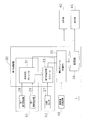
- FIG. 2 is a schematic diagram showing the configuration of the wheel loader 1.
- the wheel loader 1 includes an engine 20, a power take-out unit (PTO) 22, a power transmission mechanism 23, a cylinder drive unit 24, a first angle detector 29, a first processing device 30, a forward / reverse switching device 49, a display unit 40, and an output. A portion 45 is provided.
- Engine 20 is, for example, a diesel engine.
- the output of the engine 20 is controlled by adjusting the amount of fuel injected into the cylinder of the engine 20.
- the power take-out unit 22 is a device that distributes the output of the engine 20 to the power transmission mechanism 23 and the cylinder drive unit 24.
- the power transmission mechanism 23 is a mechanism that transmits the driving force from the engine 20 to the front wheels 4a and the rear wheels 4b.
- the power transmission mechanism 23 shifts and rotates the rotation of the input shaft 21.
- a rotation sensor 27 for detecting the rotation speed of the output shaft 23 a is attached to the output shaft 23 a of the power transmission mechanism 23.
- the wheel loader 1 includes a rotation sensor 27.
- the rotation sensor 27 functions as a movement detector that detects movement by the traveling device 4.
- the rotation sensor 27 functions as a vehicle speed detector for detecting the vehicle speed.
- the cylinder drive unit 24 has a work machine pump 25 and a control valve 26.
- the output of the engine 20 is transmitted to the work machine pump 25 via the power take-out unit 22. Further, the hydraulic oil discharged from the work machine pump 25 is supplied to the boom cylinder 16 and the bucket cylinder 19 via the control valve 26.
- the first hydraulic pressure detector 28 for detecting the hydraulic pressure in the oil chamber of the boom cylinder 16 is attached to the boom cylinder 16.
- the wheel loader 1 includes a first hydraulic pressure detector 28.
- the first oil pressure detector 28 detects the oil pressure (bottom pressure) in the bottom oil chamber through which pressure oil flows when the boom 14 is raised.
- the first oil pressure detector 28 functions as a bucket state detector that detects the state of the bucket 6.
- the first angle detector 29 is, for example, a potentiometer attached to the boom pin 10.
- the first angle detector 29 detects a boom angle representing the lift angle (tilt angle) of the boom 14.
- the boom angle ⁇ is an angle of a straight line LB extending in a direction from the center of the boom pin 10 toward the center of the bucket pin 17 with respect to a horizontal line LH extending forward from the center of the boom pin 10.
- the boom angle ⁇ is positive when the straight line LB is above the horizontal line LH.
- the boom angle ⁇ is negative when the straight line LB is below the horizontal line LH.
- the forward / reverse switching device 49 is one of the operation devices arranged in the cab 5.
- the forward / reverse switching device 49 includes an operation member 49a and a member position detection sensor 49b.
- the operation member 49a is operated by an operator to instruct switching between forward and reverse travel of the vehicle.
- the operation member 49a can be switched to forward, neutral, and reverse positions.
- the member position detection sensor 49b detects the position of the operation member 49a.
- the first processing device 30 is composed of a microcomputer including a storage device such as a RAM and a ROM, and an arithmetic device such as a CPU.
- the first processing device 30 may be realized as part of the function of the controller of the wheel loader 1 that controls the operation of the engine 20, the work machine 3, the power transmission mechanism 23, and the like.
- the first processing device 30 includes an output shaft rotation speed signal detected by the rotation sensor 27, a boom angle signal detected by the first angle detector 29, and a boom detected by the first hydraulic pressure detector 28.
- a bottom pressure signal of the cylinder 16 and a forward / reverse command signal detected by the forward / reverse switching device 49 are input.
- the 1st processing apparatus 30 integrates the conveyance work information of the load of the bucket 6 based on the input signal or more.
- the transportation work information is, for example, the number of transportation work, the total transportation weight, the total transportation distance, and the total work amount.
- the number of times of carrying work represents the number of times of carrying out a predetermined carrying work such as V-shape from the start to the end of the integration.
- the period from the start to the end of the integration means a period during which the operator operates the wheel loader 1 within a predetermined time such as one day. The period may be managed separately for each operator. Further, the period may be set manually by an operator.
- the total transported weight is the total weight of the load transported by the bucket 6 from the start to the end of the integration.
- the total transport distance is the total distance that the wheel loader 1 has moved in a state where the bucket 6 is loaded from the start to the end of the integration.
- the total work amount is a product of the total transport weight and the total transport distance from the start to the end of the integration.
- the display unit 40 is a monitor arranged on the cab 5 and visually recognized by the operator.
- the display unit 40 displays the transport work information counted by the first processing device 30.
- the output unit 45 outputs the conveyance work information to a server (second processing device 70) installed outside the wheel loader 1.
- the output unit 45 may have a communication function such as wireless communication, for example, and may communicate with the input unit 71 of the second processing device 70.
- the output unit 45 may be an interface of a portable storage device (such as a memory card) that can be accessed by the input unit 71 of the second processing device 70, for example.
- the second processing device 70 has a display unit 75 corresponding to a monitor function, and can display the transport work information output from the output unit 45.
- FIG. 3 is a block diagram illustrating a detailed configuration of the first processing device 30 according to the first embodiment.
- the first processing device 30 includes a state determination module 31, a travel distance measurement module 33, and an integration module 35.
- the first processing device 30 programs that execute the functions of the state determination module 31, the travel distance measurement module 33, and the integration module 35 are stored in the storage device of the first processing device 30. .
- the first processing device 30 executes the functions of the state determination module 31, the travel distance measurement module 33, and the integration module 35.
- the first processing device 30 may be realized by an integrated circuit.
- the first oil pressure detector 28, the first angle detector 29, and the state determination module 31 constitute a state determination unit 51 that detects the loaded state of the bucket 6. Based on the bottom pressure of the boom cylinder 16 detected by the first hydraulic pressure detector 28 and the boom angle detected by the first angle detector 29, the state determination module 31 loads and unloads the bucket 6. The state is determined.
- the loaded state means a state where the bucket 6 is loaded.
- An empty state means a state in which no load is loaded on the bucket 6.
- the state determination module 31 calculates a moving average of the bottom pressure at a predetermined time interval, and determines that the load is in a loaded state if the moving average of the bottom pressure is equal to or greater than the first threshold value.
- the state determination module 31 determines an empty state when the moving average of the bottom pressure is equal to or less than a second threshold value that is smaller than the first threshold value.
- the state determination module 31 determines that the state is the same as the previous state.
- the first threshold value and the second threshold value are set in advance, and stored in the storage device of the first processing device 30 in the form of a table, for example.
- the first threshold value and the second threshold value are determined according to the boom angle.
- FIG. 4 shows an example of the relationship between the boom angle ⁇ and the bottom pressure P for each loaded weight of the bucket 6.
- curves MIN and MAX indicate cases where the bucket 6 is empty and is loaded with a rated weight.
- Curves TH1 and TH2 indicate the first threshold value and the second threshold value, respectively.
- the first threshold value TH1 can be determined, for example, by measuring in advance the bottom pressure P1 corresponding to each boom angle ⁇ k when a first predetermined proportion of the rated weight is loaded on the bucket 6.
- the second threshold value TH2 can be determined, for example, by measuring in advance the bottom pressure P2 corresponding to each boom angle ⁇ k when a second predetermined proportion of the rated weight is loaded on the bucket 6. Since the second predetermined ratio is smaller than the first predetermined ratio, the second threshold value is smaller than the first threshold value.
- the first predetermined ratio is set to a value that is not erroneously detected as a loaded state when performing a grading operation for leveling the ground by moving the bucket 6 in contact with the ground.
- the second predetermined ratio is desirably set smaller than the first predetermined ratio by a predetermined value so that the wheel loader 1 is not in the loaded state but is erroneously determined to be in the empty state due to a change in hydraulic pressure. .
- the state determination unit 51 may estimate the loaded weight of the bucket 6 when determining the loaded state.
- the state determination module 31 has, for example, a list that defines the correspondence between the bottom pressure and the estimated load weight for each boom angle, and estimates the load weight of the bucket 6 from the moving average of the bottom pressure.
- the travel distance measurement module 53 that measures the travel distance is configured by the travel distance measurement module 33 and the rotation sensor 27.
- the travel distance measurement module 33 calculates the vehicle speed from the rotation speed of the output shaft 23 a detected by the rotation sensor 27.
- the travel distance measuring unit 53 calculates the travel distance based on the vehicle speed. For example, if the sampling interval of the rotation sensor 27 is T and the absolute value of the vehicle speed at each sampling time is Vi, the travel distance measurement module 33 calculates the travel distance by integrating the product of Vi and T.
- the travel distance is calculated as a positive value regardless of the traveling direction of the wheel loader 1. Therefore, even when the wheel loader 1 performs a shuttle operation that switches from reverse to forward, the sum of the travel distance moved during forward travel and the travel distance moved during reverse travel is the travel distance measurement. Calculated by module 33.
- the travel distance measurement unit 53 may receive the determination result of the state determination unit 51 (state determination module 31) and measure the travel distance only for the time when it is determined as the loaded state.
- the accumulating module 35 constitutes an accumulating unit that automatically accumulates the load carrying work information of the bucket 6 when traveling for a predetermined distance or more in the loaded state.
- the integration module 35 receives the forward / reverse command detected by the forward / reverse switching device 49 and the travel distance measured by the travel distance measurement module 33.
- the accumulation module 35 may further receive the determination result of the state determination module 31 and the estimated load weight of the bucket 6.
- the accumulating module 35 obtains the travel distance while the loaded state continues after being switched to reverse by the forward / reverse switching device 49. Then, when the travel distance becomes equal to or greater than the predetermined distance, the accumulation module 35 accumulates the transportation work information.
- the integrating module 35 increases the number of transportation work by one.
- the integration module 35 adds the estimated load weight of the bucket 6 input from the state determination module 31 to the total transport weight after the start of integration.
- the integrating module 35 adds the moving distance of the wheel loader 1 until it is determined to be an empty state to the total transporting distance after starting the integration.
- the integration module 35 calculates the product of the movement distance of the wheel loader 1 and the estimated load weight until the total work amount after the start of the integration is determined to be empty. Add
- the predetermined distance for accumulating transport work information is called a travel distance threshold.
- the travel distance threshold is set in advance based on the nature of the transportation work assumed by the wheel loader 1 and stored in the storage device of the first processing device 30. Details of the method of setting the travel distance threshold will be described later.
- the accumulation module 35 does not further accumulate the transportation work information until the state determination module 31 determines that the state is empty after the transportation work information is accumulated. .
- the number of transportation operations is not counted more than once for each operation of loading the load onto the dump truck 200.
- the estimated loading weight is not added more than twice for one operation of loading the load onto the dump truck 200.
- the accumulation module 35 outputs the load carrying work information of the bucket 6 accumulated as described above to the storage unit 39.
- the storage unit 39 is configured as a part of the storage device of the first processing device 30.
- the storage unit 39 stores the load carrying work information of the bucket 6 accumulated by the accumulation module 35.
- the output unit 45 is an interface of a portable storage device (such as a memory card)
- the storage unit 39 may be a portable storage device.
- the display unit 40 reads and displays the transport work information stored in the storage unit 39 or the like.
- the output unit 45 outputs the transport work information stored in the storage unit 39 to the second processing device 70.
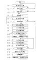
- FIG. 5 is a flowchart showing the flow of processing of the first processing apparatus 30 according to the first embodiment.
- the first processing device 30 determines the loaded state of the bucket 6 based on the output of the first oil pressure detector 28 (bucket state detector).
- 1 information D1 is acquired (step S1).
- the first information D1 is, for example, a moving average of the bottom pressure of the boom cylinder 16.
- the 1st processing apparatus 30 determines whether it is a loaded state based on the 1st information D1 (step S2). When it is not determined as a loaded state (No in step S2), the process returns to step S1.
- the first processing device 30 waits until it is switched to the reverse (No in step S3; repeats steps S1 to S3).
- the first processing device 30 (travel distance measurement unit 53) sets the travel distance of the wheel loader 1 to an initial value of 0. (Step S4).
- the first processing device 30 acquires the first information D1 (step S5).
- the 1st processing apparatus 30 determines whether it is a loaded state based on the 1st information D1 (step S6). Steps S5 and S6 are the same as steps S1 and S2, respectively. When it is not determined as a loaded state (No in step S6), the process returns to step S1.
- the first processing device 30 calculates the estimated loaded weight of the bucket 6 (step S7).
- the 1st processing apparatus 30 acquires the 2nd information D2 for calculating
- the second information D2 is, for example, the rotation speed of the output shaft 23a calculated from the rotation sensor 27.
- the first processing device 30 measures the travel distance in the loaded state (step S9). Specifically, for each sampling time, the first processing device 30 (travel distance measurement module 33) calculates the vehicle speed Vi from the rotational speed of the output shaft 23a, and calculates the product of the vehicle speed Vi and the sampling interval T at the time. Add to the distance traveled.
- the first processing device 30 determines whether or not the travel distance is equal to or greater than the travel distance threshold (step S10). If the travel distance is less than the travel distance threshold (No in step S10), the process returns to step S5.
- the first processing device 30 integrates the number of transport operations and the total transport weight (Step S11). In this case, the 1st processing apparatus 30 (accumulation part 35) increases the frequency
- the first processing device 30 continuously acquires the second information D2 (step S12), and continuously measures the travel distance in the loaded state (step S13).
- the first processing device 30 acquires the first information D1 (step S14).
- the processes in steps S12, S13, and S14 are the same as steps S8, S9, and S1 (S5), respectively.
- the 1st processing apparatus 30 determines whether it is an empty state based on the 1st information D1 (step S15). If it is not determined that the vehicle is in an empty state (No in step S15), the processes in steps S12 to S15 are repeated.
- the first processing device 30 calculates the load travel distance (step S16).
- the loaded travel distance is the total travel distance traveled by the wheel loader 1 from when the travel distance is set to 0 in step S4 until the empty load state is detected in step S15.
- the first processing device 30 integrates the work amount (step S17).
- the workload is the product of the estimated load weight obtained in step S7 and the load travel distance obtained in step S16.
- the first processing device 30 accumulates the total transport distance and the total work amount (step S18).
- the first processing device 30 may add the estimated load weight calculated in step S16 to the total transport distance after the accumulation is started, and the total work after the accumulation is started.
- the amount of work calculated in step S17 may be added to the amount.
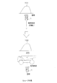
- the V-shape operation is an operation of loading a load such as earth and sand on the dump truck 200 or the like.
- the wheel loader 1 thrusts into a ground 100 such as earth and sand, loads the bucket 6, and lifts the bucket 6.
- the wheel loader 1 is in a loaded state (Yes in step S2).
- step S3 the vehicle is switched to reverse by the forward / reverse switching device 49 of the wheel loader 1 (Yes in step S3), and the wheel loader 1 moves backward in the loaded state (“reverse load” in FIG. 6).
- steps S4 to S6 are executed, and step S6 is Yes, so steps S7 to S9 are also executed.
- the load weight W at the time of reverse travel is measured by the first processing device 30 (state determination unit 51).
- the travel distance L1 during reverse travel is measured by the first processing device 30 (travel distance measurement unit 53).
- step S6 the travel distance in the forward direction is also added to L1.
- the above-described travel distance threshold is set to a value shorter than the total travel distance (L1 + L2) after switching to the reverse travel.
- the travel distance threshold is determined on the basis of the travel distance L in the loaded state when the wheel loader 1 performs an I-shaped work having a travel distance shorter than the total travel distance (L1 + L2).
- the description will focus on the differences between I-shape work and V-shape work.
- the dump truck 200 enters between the ground 100 and the retracted wheel loader 1.
- the wheel loader 1 loads the load of the bucket 6 onto the dump truck 200.
- the wheel loader 1 moves forward toward the natural ground 100 in an empty state. Therefore, the traveling distance of the wheel loader 1 in the loaded state in the I-shape operation is a distance L that is reversely moved in the loaded state.
- the travel distance threshold value may be a length corresponding to the vehicle width distance of the dump truck 200, for example.
- the total travel distance after switching to the reverse in either the “reverse load” or “forward load” process is equal to or greater than the travel distance threshold, and at that stage, step S11 The number of transport operations and the total transport weight will be integrated.
- Step S12 and S13 After the total travel distance of the wheel loader 1 becomes equal to or greater than the travel distance threshold, the travel distance is continuously measured (Steps S12 and S13), and it is determined whether or not the vehicle is continuously in an empty state (Step S12). Since S14 and S15) are the loaded state of the wheel loader 1, the processes of steps S12 to S15 are repeated. Next, in a state where the wheel loader 1 is located near the dump truck 200, the operator operates the wheel loader 1 to lower the load of the bucket 6 onto the dump truck 200. Therefore, the wheel loader 1 is in an empty state (Yes in step S15).
- step S16 the load travel distance (L1 + L2) is calculated in step S16, and the work amount (L1 + L2) ⁇ W is calculated in step 17. Finally, in step S18, the total transport distance and the total work amount are integrated.
- the first processing apparatus 30 can appropriately count the number of times of carrying work with one V-shaped work as the number of times of carrying work. Further, the first processing device 30 can appropriately accumulate the total transport weight, the total transport distance, and the total work amount.
- the 1st processing apparatus 30 incorporated in the wheel loader 1 is performing all the processes until it accumulate
- a part of the processing until the transportation work information is integrated may be processed by a server (second processing device 70) installed outside the wheel loader 1.
- a first processing apparatus and a second processing apparatus that perform such processing will be described as a second embodiment. In the second embodiment, the description overlapping with that of the first embodiment is omitted, and only different contents will be described.
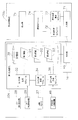
- FIG. 8 is a block diagram illustrating a detailed configuration of the first processing device 30a and the second processing device 70a according to the second embodiment.
- the configuration of the wheel loader 1a other than the first processing device 30a is the same as the configuration of the wheel loader 1 according to the first embodiment.
- the second processing device 70a is a server that receives data output from the first processing device 30a and integrates the transport work information.
- the first processing device 30 a includes a first information generation module 32, a second information generation module 34, a third information generation module 36, and a storage unit 39.
- the second processing device 70a includes at least an input unit 71, an integration module 74, and a display unit 75.
- the second processing device 70a may further include a state determination module 72 and a travel distance calculation module 73.
- the first information generation module 32 and the state determination module 72 realize the same function as the state determination module 31 of the first embodiment.
- the state determination module 72 may be omitted.
- the first information generation module 32 uses, for example, any of the following information of the bucket 6 based on the outputs from the first oil pressure detector 28 (bucket state detector) and the first angle detector 29. It outputs as the 1st information D1 for discriminating a loading state.
- the state determination module 72 of the state determination module 31 of the first embodiment uses, for example, any of the following based on outputs from the first oil pressure detector 28 (bucket state detector) and the first angle detector 29.
- the intermediate processing result may be output as first information D1 for determining the loaded state of the bucket 6.
- Second information generation module 34 and the travel distance calculation module 73 realize the same function as the travel distance measurement module 33 of the first embodiment. When the second information generation module 34 executes all the functions of the travel distance measurement module 33 of the first embodiment, the travel distance calculation module 73 may be omitted.
- the second information generation module 34 determines the travel distance of the wheel loader 1a from the start time to the end time of the “loading state” based on the output from the rotation sensor 27 (movement detector).
- the second information D2 for obtaining the travel distance is output.
- the second information generation module 34 is based on the output from the rotation sensor 27 (movement detector). For example, any of the following intermediate processing results may be output as the second information D2 for obtaining the travel distance of the wheel loader 1a.
- the rotational speed of the output shaft 23a at each sampling time The vehicle speed at each sampling time The travel distance from one sampling time to the next sampling time
- the third information generation module 36 and the integration module 74 perform integration in the first embodiment.
- the same function as the module 35 is realized.
- the third information generation module 36 may output, for example, the following intermediate processing result as the third information D3 based on the forward / reverse command detected by the forward / reverse switching device 49.
- the third information generation module 36 further receives, from the second information generation module 34, information related to the load travel distance of the wheel loader 1a from the start time to the end time of the “load state”. For each period until the end, information that summarizes the total travel distance in these periods (hereinafter, this information is referred to as preprocessed information) may be output as the third information D3.
- the storage unit 39 stores the first information D1, the second information D2, and the third information D3 output from the first to third information generation modules 32, 34, and 36.
- the storage unit 39 may not store the first information D1, the second information D2, and the third information D3 as different data, for example, the first information D1, the second information D2, and the third information at each sampling time.
- Information D3 may be stored as integrated data.
- storage part 39 does not need to memorize
- the operations of the first processing device 30a and the second processing device 70a in the second embodiment are basically the same as the operations of the first embodiment shown in FIG. 5 except that the operating subject is different from the first embodiment.
- the first information generation module 32 executes steps S1, S5, and S14
- the first information generation module 32 or the state determination module 72 executes steps S2, S6, S7, and S15
- the second information generation module 34 executes steps S8 and S12
- the second information generation module 34 or the travel distance calculation module 73 executes steps S9, S13, and S16.
- the third information generation module 36 or the integration module 74 executes step S3, and the integration module 74 executes steps S10, S11, S17, and S18.
- the second processing device 70a installed outside the wheel loader 1a can accumulate the transport work information of the wheel loader 1a as in the first embodiment.
- the wheel loader 1 automatically determines the loaded state of the bucket 6 and accumulates the transport work information on the assumption that the load has been transported when traveling over a predetermined travel distance threshold in the loaded state.
- the wheel loader 1a according to the second embodiment automatically extracts information (the first information D1 to the third information D3) related to the accumulation of the transport work information from the operation of the wheel loader 1a according to the normal work instruction performed by the operator. And output to the second processing device 70a. Therefore, the operator does not need to perform a special operation for integrating the transportation work information in the transportation work. Therefore, the operator load is reduced.
- the transportation work information is not accumulated until the travel distance in the loaded state is equal to or greater than the travel distance threshold. Accordingly, it is possible to prevent the operation of adjusting the shape of the natural ground (pick-up) by the bucket 6 from being erroneously detected as the transporting operation.
- the wheel loader 1 (accumulation unit 35) according to the first embodiment and the second processing device 70a (accumulation module 74) according to the second embodiment are set to a predetermined travel distance threshold after being switched to reverse in the loaded state.
- the transportation work information is accumulated.
- V shape and I shape assumed as the transporting work of the wheel loaders 1 and 1a when transporting, it is always switched to the reverse in the loaded state, thereby further improving the detection accuracy of the transporting work.
- the wheel loader 1 (accumulation unit 35) according to the first embodiment and the second processing device 70a (accumulation module 74) according to the second embodiment integrate the conveyance work information related to the number of conveyance operations and the total conveyance weight. After that, the transportation work information is not further accumulated until it is determined that the state is empty. As a result, it is prevented that two or more times are accumulated in one transport operation.
- the wheel loaders 1 and 1a detect the bottom pressure of the boom cylinder 16 by the first oil pressure detector 28, and when the bottom pressure is equal to or higher than the first threshold, it is determined that the vehicle is in a loaded state.
- the posture of the bucket 6 is adjusted to a specific posture as in a conventionally known method for measuring the loaded weight of a bucket (see, for example, JP-A-2001-99701). There is no need. For this reason, an operator load is further reduced.
- a bucket state detector for detecting the state of the bucket 6 is configured at low cost.
- the first threshold value and the second threshold value are determined according to the boom angle. Even if the load applied to the bucket 6 is the same, the bottom pressure changes according to the boom angle, and thus the first threshold value and the second threshold value are determined in this way, so that the detection accuracy of the loaded state and the empty state is detected. Will improve.
- the “loaded state” and the “empty state” are determined based on the bottom pressure of the boom cylinder 16 and the boom angle, but the bottom pressure of the bucket cylinder 19 and the bucket 6 Based on the tilt angle, the “loaded state” and the “empty state” may be determined.
- the wheel loader 1 detects the second hydraulic pressure detector 47 for detecting the hydraulic pressure in the oil chamber of the bucket cylinder 19 and the tilt angle representing the upward tilt angle of the bucket 6.
- a two-angle detector 48 detects the oil pressure (bottom pressure) in the bottom-side oil chamber through which pressure oil flows when the bucket 6 is tilted upward.
- the second oil pressure detector 47 functions as a bucket state detector that detects the state of the bucket 6.
- the second angle detector 48 is, for example, a potentiometer attached to the bucket pin 17.
- the first threshold value of the bottom pressure of the bucket cylinder 19 according to the tilt angle may be determined in advance. And it is good to determine "load state” and "empty state” by the threshold value process shown by the above-mentioned embodiment. Even with such a determination method, the same effect as in the case of determining by the boom cylinder 16 and the boom angle can be obtained.
- the wheel loader 1 or 1a may be attached to the bucket 6 with a weight sensor, and the weight sensor may determine the “loaded state” and the “empty state”.
- the first information D1 may be generated from the output of the weight sensor.
- the weight sensor functions as a bucket state detector that detects the state of the bucket.
- the “loaded state” and “empty state” are determined based on the bottom pressure of the boom cylinder 16 and the boom angle, but the tilt angle of the bucket 6 is equal to or greater than a predetermined angle. By detecting whether or not the vehicle is tilted, the “loaded state” and the “empty state” may be determined.
- the wheel loader 1 includes the second angle detector 48 described above.
- the second angle detector 48 is, for example, a potentiometer attached to the bucket pin 17 or a proximity switch.
- the rotation sensor 27 may detect the rotation speed of the input shaft 21 of the power transmission mechanism 23 instead of the output shaft 23a of the power transmission mechanism 23.
- the vehicle speed may be calculated in consideration of the reduction ratio of the power transmission mechanism 23.
- the travel distance may be measured by a positioning sensor such as a GPS or a laser instead of the rotation sensor 27.
- the second information D2 may be generated from the output of the positioning sensor.
- the positioning sensor functions as a movement detector that detects movement by the traveling device 4.
- the integrating module (integrating unit) 35 may not receive a signal related to the forward / reverse switching command from the forward / reverse switching device 49.
- the first processing device 30a may omit the third information generation module 36.
- the integration module 74 may integrate the transport work information without inputting the third information D3. In the above case, step S3 in FIG. 5 may be omitted.
- the third information generation module 36 does not receive a signal related to the forward / reverse switching command from the forward / reverse switching device 49, and for each period from the transition to the loading state until the end. You may output the information which put together the total movement distance in a period as the 3rd information D3 which concerns on pre-processed information.
- the integration module 74 may integrate the transport work information based on the preprocessed information.
- the storage unit 39 and the output unit 45 of FIG. 3 may be omitted.
- the integrating module 35 may directly output the transportation work information to the display unit 40.
- not all processing shown in FIG. 5 may be real-time processing, and the first information D1, the second information D2, and the third information D3 recorded in time series are analyzed and batch processed.
- Transportation work information may be integrated by being processed.
Landscapes
- Engineering & Computer Science (AREA)
- Mining & Mineral Resources (AREA)
- Civil Engineering (AREA)
- General Engineering & Computer Science (AREA)
- Structural Engineering (AREA)
- Physics & Mathematics (AREA)
- General Physics & Mathematics (AREA)
- Mechanical Engineering (AREA)
- Operation Control Of Excavators (AREA)
- Component Parts Of Construction Machinery (AREA)
Abstract
ホイールローダは、ブームと、バケットと、走行装置と、走行距離計測部と、状態判定部と、積算部と、を備える。バケットは、ブームの先端に取り付けられる。走行距離計測部は、走行距離を計測する。状態判定部は、バケットの積荷状態を判定する。積算部は、積荷状態において所定の距離以上走行した場合、バケットの荷の運搬作業情報を自動で積算する。
Description
ホイールローダと、当該ホイールローダの運搬作業情報の自動積算方法とを開示する。
ホイールローダに搭乗するオペレータの仕事量を管理するために、ホイールローダのバケットの荷積作業、トラックへの荷下ろし作業を計数する手動カウンタ装置が知られている(特許文献1参照)。
特許文献1に係るカウンタ装置では、オペレータが、バケットの荷積作業、トラックへの荷下ろし作業のそれぞれに対応するボタンを、各作業が行われるたびに押す必要がある。このため、オペレータ作業が煩雑であるという問題があった。
本明細書は、バケットの荷積作業とトラックやホッパーへの荷下ろし作業とを含むバケットの荷の運搬作業を自動で検出し、オペレータ負荷を軽減するホイールローダを開示する。
第1の態様に係るホイールローダは、ブームと、バケットと、走行装置と、走行距離計測部と、状態判定部と、積算部と、を備える。バケットは、ブームの先端に取り付けられる。走行距離計測部は、走行距離を計測する。状態判定部は、バケットの積荷状態を判定する。積算部は、積荷状態において所定の距離以上走行した場合、バケットの荷の運搬作業情報を自動で積算する。
当該運搬作業情報は、運搬作業回数、総運搬重量、総運搬距離、総仕事量のうちの少なくとも1つであるとよい。
当該ホイールローダは、走行装置の前進及び後進の切換を指示する前後進切換装置をさらに備えるとよい。積算部は、積荷状態において後進へ切り換えられた後に所定の距離以上走行した場合、運搬作業情報を積算するとよい。
状態判定部は、空荷状態をさらに判定するとよい。積算部は、運搬作業情報を積算した後、空荷状態と判定されるまで、運搬作業情報をさらに積算しないとよい。
当該ホイールローダは、ブームまたはバケットを駆動する油圧シリンダをさらに備えるとよい。状態判定部は、油圧シリンダの油室内の油圧を検出する油圧検出器を含むとよい。状態判定部は、油圧が第1閾値以上の場合、積荷状態と判定するとよい。
状態判定部は、油圧が第1閾値より小さい第2閾値以下である場合、空荷状態と判定するとよい。
油圧シリンダは、ブームを昇降させるブームシリンダであるとよい。油圧検出器は、ブームを上昇させる場合に圧油を流入させる側のブームシリンダの油室内の油圧を検出するとよい。
状態判定部は、ブームのチルト角度であるブーム角度を検出する角度検出器を含むとよい。第1閾値は、ブーム角度に応じて定められるとよい。第2閾値は、ブーム角度に応じて定められるとよい。
油圧シリンダは、バケットを駆動するバケットシリンダであるとよい。油圧検出器は、バケットを上方向に傾ける場合に圧油を流入させる側のバケットシリンダの油室内の油圧を検出するとよい。
状態判定部は、バケットのチルト角度であるバケット角度を検出する角度検出器を含むとよい。第1閾値は、バケット角度に応じて定められるとよい。第2閾値は、バケット角度に応じて定められるとよい。
状態判定部は、バケット角度が所定の閾値以上の場合、積荷状態と判定するとよい。
状態判定部は、バケットのチルト状態を検出する位置検出器を含むとよい。状態判定部は、バケットのチルト状態を検出した場合、積荷状態と判定するとよい。
走行距離計測部は、車速を検出するための車速検出器を含むとよい。走行距離計測部は、車速に基づいて走行距離を算出するとよい。
当該ホイールローダは、運搬作業情報を表示する表示部をさらに備えるとよい。
当該ホイールローダは、運搬作業情報を出力する出力部をさらに備えるとよい。
第2の態様に係るホイールローダの運搬作業情報の自動積算方法は、バケット、走行装置、走行装置による移動を検出する移動検出器、及びバケットの状態を検出するバケット状態検出器を備えるホイールローダと処理装置とによる、ホイールローダの運搬作業情報の自動積算方法である。当該方法は、以下の第1~第3ステップを含む。第1ステップでは、バケット状態検出器の出力をもとに、バケットの積荷状態を判別するための第1情報を取得する。第2ステップでは、移動検出器の出力をもとに、ホイールローダの走行距離を求めるための第2情報を取得する。第3ステップでは、処理装置が、第1情報と第2情報とに基づいて、ホイールローダが積荷状態において所定の距離以上走行した場合に、運搬作業情報を積算する。
第1の態様に係るホイールローダ及び第2の態様に係るホイールローダの運搬作業情報の自動積算方法は、バケットの積荷状態を判定して、積荷状態で所定の距離以上走行すると、荷を運搬したとして運搬作業情報を積算する。したがって、オペレータは運搬作業において運搬作業情報を積算するための特別な操作を行う必要がない。よって、オペレータ負荷が軽減される。
以下、図面を参照して、本発明の実施形態について説明する。図1は、本発明の実施形態に係るホイールローダ1の側面図である。図1に示すように、ホイールローダ1は、車体フレーム2と、作業機3と、走行装置4と、キャブ5とを備えている。走行装置4は、走行輪4a,4bを含む。ホイールローダ1は、走行輪4a,4bが回転駆動されることにより自走可能であり、作業機3を用いて所望の作業を行うことができる。
車体フレーム2は、前フレーム11と後フレーム12とを含む。前フレーム11と後フレーム12とは互いに左右方向に揺動可能に取り付けられている。前フレーム11と後フレーム12とには、ステアリングシリンダ13が取り付けられている。ステアリングシリンダ13は、油圧シリンダである。ステアリングシリンダ13がステアリングポンプ(図示せず)からの作動油によって伸縮することによって、ホイールローダ1の進行方向が左右に変更される。
前フレーム11には、作業機3および走行輪4aが取り付けられている。作業機3は、ブーム14と、バケット6とを含む。ブーム14の基端部は、ブームピン10によって前フレーム11に回転自在に取付けられている。バケット6は、ブーム14の先端に位置するバケットピン17によって、回転自在にブーム14に取付けられている。前フレーム11とブーム14とはブームシリンダ16により連結されている。ブームシリンダ16は、油圧シリンダである。ブームシリンダ16が作業機ポンプ25(図2参照)からの作動油によって伸縮することによって、ブーム14が昇降する。つまり、ブームシリンダ16は、ブーム14を駆動する。
また、作業機3は、チルトアーム18と、バケットシリンダ19と、チルトロッド15とをさらに含む。チルトアーム18は、ブーム14のほぼ中央において、ブーム14に回転自在に支持されている。バケットシリンダ19は、チルトアーム18の基端部と前フレーム11とを連結する。チルトロッド15は、チルトアーム18の先端部とバケット6とを連結する。バケットシリンダ19は、油圧シリンダである。バケットシリンダ19が作業機ポンプ25(図2参照)からの作動油によって伸縮することによって、バケット6が上下に回動する。つまり、バケットシリンダ19は、バケット6を駆動する。
後フレーム12には、キャブ5及び走行輪4bが取り付けられている。すなわち、キャブ5は、ブーム14の後方に配置される。キャブ5は、車体フレーム2上に載置されている。キャブ5内には、オペレータが着座するシートや操作装置などが配置されている。
図2は、ホイールローダ1の構成を示す模式図である。ホイールローダ1は、エンジン20、動力取り出し部(PTO)22、動力伝達機構23、シリンダ駆動部24、第1角度検出器29、第1処理装置30、前後進切換装置49、表示部40、出力部45を備えている。
エンジン20は、例えばディーゼルエンジンである。エンジン20の出力は、エンジン20のシリンダ内に噴射する燃料量を調整することにより制御される。
動力取り出し部22は、エンジン20の出力を、動力伝達機構23とシリンダ駆動部24とに振り分ける装置である。
動力伝達機構23は、エンジン20からの駆動力を前輪4a及び後輪4bに伝達する機構である。動力伝達機構23は、入力軸21の回転を変速して出力する。
動力伝達機構23の出力軸23aには、出力軸23aの回転速度を検出するための回転センサ27が取り付けられている。ホイールローダ1は、回転センサ27を含む。回転センサ27は、走行装置4による移動を検出する移動検出器として機能する。別の言い方をすれば、回転センサ27は、車速を検出するための車速検出器として機能する。
シリンダ駆動部24は、作業機ポンプ25及び制御弁26を有している。作業機ポンプ25へは動力取り出し部22を介してエンジン20の出力が伝達される。また、作業機ポンプ25から吐出された作動油は、制御弁26を介してブームシリンダ16及びバケットシリンダ19に供給される。
ブームシリンダ16には、ブームシリンダ16の油室内の油圧を検出するための第1油圧検出器28が取り付けられている。ホイールローダ1は、第1油圧検出器28を含む。第1油圧検出器28は、ブーム14を上昇させる場合に圧油を流入させる、ボトム側の油室内の油圧(ボトム圧)を検出する。第1油圧検出器28は、バケット6の状態を検出するバケット状態検出器として機能する。
第1角度検出器29は、例えば、ブームピン10に取り付けられたポテンショメータである。第1角度検出器29は、ブーム14の持ち上がり角度(チルト角度)を表すブーム角度を検出する。具体的には、図1に示すように、ブーム角度θは、ブームピン10の中心から前方に延びる水平線LHに対する、ブームピン10の中心からバケットピン17の中心に向かう方向に延びる直線LBの角度である。直線LBが水平である場合をブーム角度θ=0度と定義する。直線LBが水平線LHよりも上方にある場合にブーム角度θを正とする。直線LBが水平線LHよりも下方にある場合にブーム角度θを負とする。
前後進切換装置49は、キャブ5に配置された操作装置の1つである。前後進切換装置49は、操作部材49aと、部材位置検出センサ49bとを含む。操作部材49aは、車両の前進及び後進の切換を指示するためにオペレータによって操作される。操作部材49aは、前進、中立、及び後進の各位置に切り換えられることができる。部材位置検出センサ49bは、操作部材49aの位置を検出する。
第1処理装置30は、RAM、ROMなどの記憶装置と、CPUなどの演算装置を含むマイクロコンピュータで構成されている。第1処理装置30は、エンジン20、作業機3、動力伝達機構23等の動作を制御する、ホイールローダ1のコントローラの機能の一部として実現されてもよい。第1処理装置30には、回転センサ27によって検出される出力軸回転速度の信号と、第1角度検出器29によって検出されるブーム角度の信号と、第1油圧検出器28によって検出されるブームシリンダ16のボトム圧の信号と、前後進切換装置49によって検出される前後進指令の信号とが入力される。第1処理装置30は、入力された以上の信号に基づいて、バケット6の荷の運搬作業情報を積算する。
ここで、運搬作業情報とは、例えば、運搬作業回数、総運搬重量、総運搬距離、総仕事量である。運搬作業回数とは、当該積算を開始してから終了するまでにVシェープなどの所定の運搬作業を行った回数を表す。当該積算を開始して終了するまでの期間とは、例えば、1日などの所定の時間内においてオペレータがホイールローダ1を運転している期間を意味する。当該期間は、オペレータごとに分けて管理されるとよい。また、当該期間は、オペレータによって手動で設定されてもよい。総運搬重量とは、当該積算を開始してから終了するまでにバケット6が運搬した荷の総重量である。総運搬距離とは、当該積算を開始してから終了するまでに、バケット6に荷を積んだ状態でホイールローダ1が移動した総距離である。総仕事量とは、当該積算を開始してから終了するまでの、総運搬重量と総運搬距離との積である。
表示部40は、キャブ5に配置された、オペレータが視認するモニタである。表示部40は、第1処理装置30によって計数された運搬作業情報を表示する。出力部45は、ホイールローダ1の外部に設置されたサーバ(第2処理装置70)に、運搬作業情報を出力する。出力部45は、例えば、無線通信などの通信機能を有し、第2処理装置70の入力部71と通信してもよい。あるいは、出力部45は、例えば、第2処理装置70の入力部71がアクセス可能な携帯記憶装置(メモリカードなど)のインタフェースであってもよい。第2処理装置70は、モニタ機能にあたる表示部75を有しており、出力部45から出力された運搬作業情報を表示することができる。
[第1実施例]
図3は、第1実施例に係る第1処理装置30の詳細な構成を表すブロック図である。第1処理装置30は、状態判定モジュール31と、走行距離計測モジュール33と、積算モジュール35とを含む。
図3は、第1実施例に係る第1処理装置30の詳細な構成を表すブロック図である。第1処理装置30は、状態判定モジュール31と、走行距離計測モジュール33と、積算モジュール35とを含む。
典型的には、第1処理装置30では、状態判定モジュール31と、走行距離計測モジュール33と、積算モジュール35との各機能を実行するプログラムが第1処理装置30の記憶装置に記憶されている。演算装置が当該プログラムを実行することによって、第1処理装置30は、状態判定モジュール31と、走行距離計測モジュール33と、積算モジュール35との各機能を実行する。なお、第1処理装置30は、集積回路によって実現されてもよい。
第1油圧検出器28と、第1角度検出器29と、状態判定モジュール31とによって、バケット6の積荷状態を検出する状態判定部51が構成される。状態判定モジュール31は、第1油圧検出器28によって検出されたブームシリンダ16のボトム圧と、第1角度検出器29によって検出されたブーム角度とをもとに、バケット6の積荷状態と空荷状態とを判定する。積荷状態とは、バケット6に荷が積まれている状態を意味する。空荷状態とは、バケット6に荷が積まれていない状態を意味する。
状態判定モジュール31は、所定の時間間隔のボトム圧の移動平均を算出し、ボトム圧の移動平均が第1閾値以上の場合、積荷状態と判定する。状態判定モジュール31は、ボトム圧の移動平均が第1閾値より小さい第2閾値以下である場合、空荷状態と判定する。状態判定モジュール31は、ボトム圧の移動平均が第1閾値未満であり第2閾値より大きい場合、従前の状態と同じ状態と判定する。第1閾値及び第2閾値は、予め設定され、例えばテーブルの形式で第1処理装置30の記憶装置に記憶されている。第1閾値及び第2閾値は、ブーム角度に応じて定められる。
図4は、バケット6の積載重量ごとのブーム角度θとボトム圧Pとの関係の一例を示す。図4において、カーブMIN,MAXはそれぞれ、バケット6が空、定格重量積載の場合を示している。カーブTH1,TH2はそれぞれ、第1閾値、第2閾値を示している。第1閾値TH1は、例えば、定格重量の第1所定割合の荷がバケット6に積載されたときの各ブーム角度θkに対応するボトム圧P1を予め測定することによって定めることができる。第2閾値TH2は、例えば、定格重量の第2所定割合の荷がバケット6に積載されたときの各ブーム角度θkに対応するボトム圧P2を予め測定することによって定めることができる。第2所定割合は第1所定割合よりも小さいため、第2閾値は第1閾値よりも小さくなる。
第1所定割合は、バケット6を接地させて前進することによって整地するグレーディング作業を行う際に積荷状態と誤検出されない程度の値に設定されることが望ましい。第2所定割合は、ホイールローダ1が積荷状態であるにも関らず、油圧の変動によって誤って空荷状態と判定されないように、第1所定割合から所定値だけ小さく設定されることが望ましい。
状態判定部51(状態判定モジュール31)は、積荷状態と判定する場合、バケット6の積載重量を推定してもよい。この場合、状態判定モジュール31は、例えば、ブーム角度ごとにボトム圧と推定積載重量との対応関係を定義したリストを有し、ボトム圧の移動平均からバケット6の積載重量を推定する。
走行距離計測モジュール33と、回転センサ27とによって、走行距離を計測する走行距離計測部53が構成される。走行距離計測モジュール33は、回転センサ27によって検出された出力軸23aの回転速度から、車速を算出する。走行距離計測部53は、車速に基づいて走行距離を算出する。例えば、回転センサ27のサンプリング間隔をTとし、各サンプリング時刻の車速の絶対値をViとすれば、走行距離計測モジュール33は、ViとTの積を積算することによって、走行距離を算出する。
なお、走行距離はホイールローダ1の進行方向に依らずに正の値として算出される。したがって、ホイールローダ1が後進から前進に切換えられるようなシャトル動作を行う場合であっても、前進のときに移動した走行距離と、後進のときに移動した走行距離との和が、走行距離計測モジュール33によって算出される。
なお、走行距離計測部53(走行距離計測モジュール33)は、状態判定部51(状態判定モジュール31)の判定結果を受け取り、積荷状態と判定された時刻についてのみ走行距離を計測してもよい。
積算モジュール35は、積荷状態において所定の距離以上走行した場合、バケット6の荷の運搬作業情報を自動で積算する積算部を構成する。積算モジュール35には、前後進切換装置49が検出する前後進指令と、走行距離計測モジュール33により計測される走行距離とが入力される。積算モジュール35には、状態判定モジュール31の判定結果とバケット6の推定積載重量とがさらに入力されてもよい。
積算モジュール35は、前後進切換装置49によって後進に切り換えられた後、積荷状態が継続する間の走行距離を求める。そして、走行距離が所定の距離以上となったときに、積算モジュール35は、運搬作業情報を積算する。
運搬作業情報が運搬作業回数である場合、積算モジュール35は、運搬作業回数を1回増加する。運搬作業情報が総運搬重量である場合、積算モジュール35は、積算を開始してからの総運搬重量に、状態判定モジュール31から入力されるバケット6の推定積載重量を加える。運搬作業情報が総運搬距離である場合、積算モジュール35は、積算を開始してからの総運搬距離に、空荷状態と判定されるまでのホイールローダ1の移動距離を加える。運搬作業情報が総仕事量である場合、積算モジュール35は、積算を開始してからの総仕事量に、空荷状態と判定されるまでのホイールローダ1の移動距離と推定積載重量との積を加える。
運搬作業情報を積算するための所定の距離を走行距離閾値と呼ぶ。走行距離閾値は、ホイールローダ1が想定される運搬作業の性質に基づいて予め設定され、第1処理装置30の記憶装置に記憶される。走行距離閾値の設定方法の詳細は、後述する。
運搬作業情報が運搬作業回数または総運搬重量である場合、積算モジュール35は、運搬作業情報を積算した後は、状態判定モジュール31によって空荷状態と判定されるまで、運搬作業情報をさらに積算しない。これによって、荷をダンプトラック200に積み込む1回の作業につき、運搬作業回数が2回以上カウントされない。また、荷をダンプトラック200に積み込む1回の作業につき、推定積載重量が2回以上加算されない。積算モジュール35は、上述のように積算したバケット6の荷の運搬作業情報を、記憶部39に出力する。
記憶部39は、第1処理装置30の記憶装置の一部として構成される。記憶部39は、積算モジュール35が積算したバケット6の荷の運搬作業情報を記憶する。出力部45が携帯記憶装置(メモリカードなど)のインタフェースである場合、記憶部39は携帯記憶装置であってもよい。表示部40は、記憶部39等に記憶された運搬作業情報を読み取って表示する。出力部45は、記憶部39に記憶された運搬作業情報を第2処理装置70に出力する。
図5は、第1実施例に係る第1処理装置30の処理の流れを示すフローチャートである。本処理においては、まず、第1処理装置30(状態判定モジュール31)は、第1油圧検出器28(バケット状態検出器)の出力をもとに、バケット6の積荷状態を判別するための第1情報D1を取得する(ステップS1)。第1情報D1とは、例えば、ブームシリンダ16のボトム圧の移動平均である。そして、第1処理装置30(状態判定モジュール31)は、第1情報D1に基づき、積荷状態であるか否か判定する(ステップS2)。積荷状態と判定されない場合(ステップS2でNo)、ステップS1に戻る。
積荷状態である場合、第1処理装置30は、後進に切り替えられるまで待つ(ステップS3でNo。ステップS1からS3を繰り返す)。前後進切換装置49が後進に切り換えられたことを検出する(ステップS3でYes)と、第1処理装置30(走行距離計測部53)は、ホイールローダ1の走行距離を初期値の0に設定する(ステップS4)。
つぎに、第1処理装置30(状態判定モジュール31)は、第1情報D1を取得する(ステップS5)。第1処理装置30(状態判定モジュール31)は、第1情報D1に基づき、積荷状態であるか否か判定する(ステップS6)。ステップS5、S6の処理は、それぞれ、ステップS1、S2の処理と同じである。積荷状態と判定されない場合(ステップS6でNo)、ステップS1に戻る。
積荷状態と判定される場合(ステップS6でYes)、第1処理装置30(状態判定モジュール31)は、バケット6の推定積載重量を算出する(ステップS7)。つぎに、第1処理装置30(走行距離計測モジュール33)は、回転センサ27(移動検出器)の出力をもとに、ホイールローダ1の走行距離を求めるための第2情報D2を取得する(ステップS8)。第2情報D2とは、例えば、回転センサ27から算出される出力軸23aの回転速度である。そして、第1処理装置30(走行距離計測モジュール33)は、積荷状態における走行距離を計測する(ステップS9)。具体的には、サンプリング時刻ごとに、第1処理装置30(走行距離計測モジュール33)は、出力軸23aの回転速度から車速Viを算出し、車速Viとサンプリング間隔Tとの積を、当該時刻までの走行距離に加算する。
つぎに、第1処理装置30(積算部35)は、走行距離が走行距離閾値以上となったかどうかを判定する(ステップS10)。走行距離が走行距離閾値未満である場合(ステップS10でNo)、ステップS5に戻る。走行距離が走行距離閾値以上となった場合(ステップS10でYes)、第1処理装置30(積算部35)は、運搬作業回数と総運搬重量とを積算する(ステップS11)。この場合、第1処理装置30(積算部35)は、運搬作業回数を1回増加し、積算を開始してからの総運搬重量にステップS7で算出された推定積載重量を加える。
その後、第1処理装置30(走行距離計測モジュール33)は、第2情報D2を継続的に取得し(ステップS12)、積荷状態における走行距離を継続的に計測する(ステップS13)。第1処理装置30(状態判定モジュール31)は、第1情報D1を取得する(ステップS14)。ステップS12、S13、及びS14の処理は、それぞれ、ステップS8、S9、及び、S1(S5)と同じである。そして、第1処理装置30(状態判定モジュール31)は、第1情報D1に基づき、空荷状態であるか否か判定する(ステップS15)。空荷状態と判定されない場合(ステップS15でNo)、ステップS12~ステップS15の処理を繰り返す。
空荷状態と判定された場合(ステップS15でYes)、第1処理装置30(走行距離計測モジュール33)は、積荷走行距離を算出する(ステップS16)。積荷走行距離とは、ステップS4で走行距離が0に設定されてからステップS15で空荷状態が検出されるまでにホイールローダ1が走行した総走行距離である。そして、第1処理装置30(積算部35)は、仕事量を算出する(ステップS17)。仕事量は、ステップS7で得られた推定積載重量と、ステップS16で得られた積荷走行距離との積である。
最後に、第1処理装置30(積算部35)は、総運搬距離と総仕事量とを積算する(ステップS18)。この場合、第1処理装置30(積算部35)は、積算を開始してからの総運搬距離にステップS16で算出された推定積載重量を加えてもよく、積算を開始してからの総仕事量にステップS17で算出された仕事量を加えてもよい。ステップS18の終了後、ステップS1に戻る。
つぎに、第1実施例に係る第1処理装置30の処理の流れを、ホイールローダ1の典型的な作業であるVシェープの作業におけるホイールローダ1の各動作と対応付けながら説明する。図6に示すように、Vシェープの作業は、土砂などの荷をダンプトラック200などに積み込む作業である。まず、ホイールローダ1は、土砂などの地山100に突っ込み、バケット6に荷を積み込んで、バケット6を持ち上げる。このとき、ホイールローダ1は積荷状態である(ステップS2でYes)。
つぎに、ホイールローダ1の前後進切換装置49で後進に切り替えられ(ステップS3でYes)、ホイールローダ1は積荷状態で後進する(図6における「積荷後進」)。このとき、ステップS4~S6が実行され、ステップS6がYesとなるので、ステップS7~S9も実行される。したがって、この後進の際の積載重量Wが、第1処理装置30(状態判定部51)によって計測される。同様に、後進の際の走行距離L1が、第1処理装置30(走行距離計測部53)によって計測される。
つぎに、オペレータは、前後進切換装置49を操作し、後進から前進に切り替える。そして、ホイールローダ1は積荷状態で前進する(図7における「積荷前進」)。上述する走行距離L1が走行距離閾値未満である場合、ステップS5~S9が継続して実行される。このとき、ステップS6がYesとなるので、前進方向の走行距離もL1に加算される。
前進方向の総走行距離をL2とするとき、前述した走行距離閾値は、後進に切り替えられてからの総走行距離(L1+L2)よりも短い値に設定される。具体的には、走行距離閾値は、この総走行距離(L1+L2)よりも短い走行距離となるIシェープの作業をホイールローダ1が行うときの積荷状態の走行距離Lに基づいて定められる。
ここで、Iシェープの作業をVシェープの作業と相違する点を中心に説明する。まず、図7に示すように、ホイールローダ1が積荷状態で後進した後、ダンプトラック200が地山100と後退したホイールローダ1との間に進入する。そして、ホイールローダ1は、バケット6の荷をダンプトラック200に積み込む。最後に、ホイールローダ1は、空荷状態で地山100に向けて前進する。したがって、Iシェープの作業でのホイールローダ1の積荷状態での走行距離は、積荷状態で後進した距離Lとなる。
したがって、Iシェープの作業でも運搬作業情報が積算できるようにすることを想定すると、走行距離閾値は、例えば、ダンプトラック200の車幅距離に相当する長さとするとよい。
以上のように走行距離閾値が定められるため、「積荷後進」または「積荷前進」のいずれかの過程で後進に切り替えられてからの総走行距離が走行距離閾値以上となり、その段階でステップS11によって運搬作業回数と総運搬重量とが積算されることとなる。
ホイールローダ1の総走行距離が走行距離閾値以上となった後は、走行距離が継続して測定され(ステップS12、S13)、継続的に空荷状態となったか否かが判定される(ステップS14、S15)が、ホイールローダ1は積荷状態なので、ステップS12~S15の処理が繰り返される。次に、ホイールローダ1がダンプトラック200の近くに位置している状態で、オペレータがホイールローダ1を操作して、バケット6の荷をダンプトラック200に下ろす。したがって、ホイールローダ1は空荷状態となる(ステップS15でYes)。
このとき、ステップS16において、積荷走行距離(L1+L2)が算出され、ステップ17において、仕事量(L1+L2)×Wが算出される。最後に、ステップS18において、総運搬距離と総仕事量とが積算される。
以上のように、第1処理装置30は、1回のVシェープの作業を1回の運搬作業回数として、運搬作業回数を適切にカウントすることができる。さらに、第1処理装置30は、総運搬重量、総運搬距離、総仕事量を適切に積算することができる。
[第2実施例]
第1実施例では、ホイールローダ1に内蔵された第1処理装置30が、運搬作業情報を積算するまでの全ての処理を実行している。しかし、運搬作業情報を積算するまでの処理の一部が、ホイールローダ1の外部に設置されたサーバ(第2処理装置70)によって処理されてもよい。このような処理をする第1処理装置及び第2処理装置を第2実施例として説明する。第2実施例では、第1実施例と重複する説明を省略し、相違する内容についてのみ説明する。
第1実施例では、ホイールローダ1に内蔵された第1処理装置30が、運搬作業情報を積算するまでの全ての処理を実行している。しかし、運搬作業情報を積算するまでの処理の一部が、ホイールローダ1の外部に設置されたサーバ(第2処理装置70)によって処理されてもよい。このような処理をする第1処理装置及び第2処理装置を第2実施例として説明する。第2実施例では、第1実施例と重複する説明を省略し、相違する内容についてのみ説明する。
第2実施例では、第1処理装置、ホイールローダ、第2処理装置の符号を、それぞれ30a、1a、70aとする。図8は、第2実施例に係る第1処理装置30a及び第2処理装置70aの詳細な構成を表すブロック図である。ホイールローダ1aの第1処理装置30a以外の構成は、第1実施例に係るホイールローダ1の構成と同じである。第2処理装置70aは、第1処理装置30aが出力するデータを受け取り、運搬作業情報を積算するサーバである。
第1処理装置30aは、第1情報生成モジュール32と、第2情報生成モジュール34と、第3情報生成モジュール36と、記憶部39とを含む。第2処理装置70aは、入力部71と、積算モジュール74と、表示部75とを少なくとも含む。第2処理装置70aは、状態判定モジュール72と、走行距離算出モジュール73とをさらに含んでもよい。
第1情報生成モジュール32と、状態判定モジュール72とによって、第1実施例の状態判定モジュール31と同じ機能が実現される。第1情報生成モジュール32が状態判定モジュール31の全機能を実行する場合、状態判定モジュール72は省略されてもよい。この場合、第1情報生成モジュール32は、第1油圧検出器28(バケット状態検出器)、第1角度検出器29からの出力をもとに、例えば、以下のいずれかの情報をバケット6の積荷状態を判別するための第1情報D1として出力する。
・各サンプリング時刻における「積荷状態」「空荷状態」の判定結果
・「積荷状態」及び/又は「空荷状態」の開始・終了時刻
状態判定モジュール72が第1実施例の状態判定モジュール31の一部の機能を実行する場合、第1情報生成モジュール32は、第1油圧検出器28(バケット状態検出器)、第1角度検出器29からの出力をもとに、例えば、以下のいずれかの中間処理結果をバケット6の積荷状態を判別するための第1情報D1として出力するとよい。
・サンプリング時刻ごとのブームシリンダ16のボトム圧及びブーム角度
・サンプリング時刻ごとのブームシリンダ16のボトム圧の移動平均及びブーム角度
・サンプリング時刻ごとのブームシリンダ16のボトム圧の移動平均が(1)第1閾値以上、(2)第2閾値より大きく第1閾値未満、(3)第2閾値以下のいずれであるかを示すデータ
・1回の運搬作業におけるバケット6の推定積載重量
第2情報生成モジュール34と、走行距離算出モジュール73とによって、第1実施例の走行距離計測モジュール33と同じ機能が実現される。第2情報生成モジュール34が、第1実施例の走行距離計測モジュール33の全機能を実行する場合、走行距離算出モジュール73は省略されてもよい。この場合、第2情報生成モジュール34は、回転センサ27(移動検出器)からの出力をもとに、「積荷状態」の開始時刻から終了時刻までのホイールローダ1aの走行距離をホイールローダ1aの走行距離を求めるための第2情報D2して出力する。
走行距離算出モジュール73が第1実施例の走行距離計測モジュール33の一部の機能を実行する場合、第2情報生成モジュール34は、回転センサ27(移動検出器)からの出力をもとに、例えば、以下のいずれかの中間処理結果をホイールローダ1aの走行距離を求めるための第2情報D2として出力するとよい。
・サンプリング時刻ごとの出力軸23aの回転速度
・サンプリング時刻ごとの車速
・あるサンプリング時刻から次のサンプリング時刻までの走行距離
第3情報生成モジュール36と、積算モジュール74とによって、第1実施例の積算モジュール35と同じ機能が実現される。第3情報生成モジュール36は、前後進切換装置49が検出する前後進指令をもとに、例えば、以下の中間処理結果を第3情報D3として出力するとよい。
・サンプリング時刻ごとの前後進切換装置49の「前進」「中立」「後進」のいずれかのステータス
・「後進」ステータスの開始時刻と終了時刻の組み合わせ
・「後進」ステータスに切り替えられた時刻
また、第3情報生成モジュール36は、第2情報生成モジュール34から「積荷状態」の開始時刻から終了時刻までのホイールローダ1aの積荷走行距離にかかる情報をさらに受け取り、後進に切り替えられてから積荷状態が終了するまでの期間毎に、それらの期間における総移動距離をまとめた情報(以下、この情報を前処理済情報と呼ぶ)を第3情報D3として出力してもよい。
記憶部39は、第1~第3情報生成モジュール32,34,36から出力された第1情報D1、第2情報D2、及び第3情報D3を記憶する。記憶部39は、第1情報D1、第2情報D2、及び第3情報D3を異なるデータとして記憶しなくてもよく、例えば、サンプリング時刻ごとに第1情報D1、第2情報D2、及び第3情報D3が統合されたデータとして記憶してもよい。記憶部39は、運搬作業情報の積算において不要なデータを記憶しなくてもよい。例えば、記憶部39は、「空荷状態」の時刻での第2情報D2を記憶しなくてもよい。
第2実施例における第1処理装置30aと第2処理装置70aの動作は、動作主体が第1実施例と異なることを除いて、図5に示された第1実施例の動作と基本的に同じである。第1情報生成モジュール32がステップS1、S5、S14を実行し、第1情報生成モジュール32または状態判定モジュール72がステップS2、S6、S7、S15を実行する。第2情報生成モジュール34がステップS8、S12を実行し、第2情報生成モジュール34または走行距離算出モジュール73がステップS9、S13、S16を実行する。第3情報生成モジュール36または積算モジュール74がステップS3を実行し、積算モジュール74がステップS10、S11、S17、S18を実行する。
本実施例によれば、ホイールローダ1aの外部に設置された第2処理装置70aが、ホイールローダ1aの運搬作業情報を、第1実施例と同様に積算することができる。
[特徴]
(1)第1実施例に係るホイールローダ1は、バケット6の積荷状態を自動で判定して、積荷状態で所定の走行距離閾値以上走行すると、積荷を運搬したとして運搬作業情報を積算する。第2実施例に係るホイールローダ1aは、オペレータが行う通常の作業指示に従ったホイールローダ1aの動作から運搬作業情報の積算に係る情報(第1情報D1から第3情報D3)を自動で抽出し、第2処理装置70aに出力する。したがって、オペレータは、運搬作業において運搬作業情報を積算するための特別な操作を行う必要がない。よって、オペレータ負荷が軽減される。
(1)第1実施例に係るホイールローダ1は、バケット6の積荷状態を自動で判定して、積荷状態で所定の走行距離閾値以上走行すると、積荷を運搬したとして運搬作業情報を積算する。第2実施例に係るホイールローダ1aは、オペレータが行う通常の作業指示に従ったホイールローダ1aの動作から運搬作業情報の積算に係る情報(第1情報D1から第3情報D3)を自動で抽出し、第2処理装置70aに出力する。したがって、オペレータは、運搬作業において運搬作業情報を積算するための特別な操作を行う必要がない。よって、オペレータ負荷が軽減される。
また、積荷状態での走行距離が、走行距離閾値以上となるまで運搬作業情報が積算されない。したがって、バケット6によって地山の形を整える(かき上げ)作業が、運搬作業として誤検出されることが防止される。
(2)第1実施例に係るホイールローダ1(積算部35)及び第2実施例に係る第2処理装置70a(積算モジュール74)は、積荷状態において後進へ切り換えられた後に所定の走行距離閾値以上走行した場合、運搬作業情報を積算する。ホイールローダ1,1aの運搬作業として想定されるVシェープ、Iシェープの作業において、運搬する際は、積荷状態において必ず後進に切り替えられるため、これによって運搬作業の検出精度がさらに向上する。
(3)第1実施例に係るホイールローダ1(積算部35)及び第2実施例に係る第2処理装置70a(積算モジュール74)は、運搬作業回数及び総運搬重量に係る運搬作業情報を積算した後、空荷状態と判定されるまで当該運搬作業情報をさらに積算しない。これによって、1回の運搬作業において、2回以上積算されることが防止される。
(4)ホイールローダ1、1aはブームシリンダ16のボトム圧を第1油圧検出器28によって検出し、ボトム圧が第1閾値以上の場合、積荷状態であると判定される。これによって、バケット6の積荷状態を判定するにあたり、従来から知られているバケットの積載重量計測方法(例えば、特開2001-99701号公報参照)のようにバケット6の姿勢を特定の姿勢にあわせる必要もない。このため、オペレータ負荷がさらに軽減される。
また、積荷状態を判定するために特別のセンサをホイールローダ1、1aに設置する必要がない。したがって、バケット6の状態を検出するバケット状態検出器が安価に構成される。
(5)ボトム圧が第1閾値より小さい第2閾値以下となったときに、空荷状態と判定される。これによって、ホイールローダ1、1aが積荷状態であるにも関らず、油圧の変動によって誤って空荷状態と判定されることが防止される。
(6)第1閾値及び第2閾値がブーム角度に応じて定められる。バケット6にかかる荷重が同じであってもブーム角度に応じてボトム圧が変化するため、このように第1閾値と第2閾値とが定められることによって、積荷状態と空荷状態との検出精度が向上する。
[変形例]
本発明は以上のような実施形態に限定されるものではなく、本発明の範囲を逸脱することなく種々の変形又は修正が可能である。
本発明は以上のような実施形態に限定されるものではなく、本発明の範囲を逸脱することなく種々の変形又は修正が可能である。
上述の実施形態では、ブームシリンダ16のボトム圧と、ブーム角度とに基づいて、「積荷状態」と「空荷状態」とが判定されているが、バケットシリンダ19のボトム圧と、バケット6のチルト角とに基づいて、「積荷状態」と「空荷状態」とが判定されてもよい。
この場合、図2において、ホイールローダ1は、バケットシリンダ19の油室内の油圧を検出するための第2油圧検出器47と、バケット6の上方への傾きの角度を表すチルト角度を検出する第2角度検出器48とを含む。第2油圧検出器47は、バケット6を上方に傾ける場合に圧油を流入させる、ボトム側の油室内の油圧(ボトム圧)を検出する。第2油圧検出器47は、バケット6の状態を検出するバケット状態検出器として機能する。第2角度検出器48は、例えば、バケットピン17に取り付けられたポテンショメータである。
第2油圧検出器47及び第2角度検出器48によって「積荷状態」と「空荷状態」とが判定される場合であっても、チルト角度に応じたバケットシリンダ19のボトム圧の第1閾値、第2閾値が予め定められるとよい。そして、上述の実施形態に示された閾値処理によって、「積荷状態」と「空荷状態」とが判定されるとよい。このような判定方法であっても、ブームシリンダ16とブーム角度によって判定する場合と同様の効果が得られる。
上述の実施形態において、ホイールローダ1、1aはバケット6に重量センサを装着して、重量センサによって「積荷状態」と「空荷状態」とが判定されてもよい。第1情報D1は、重量センサの出力から生成されてもよい。この場合、重量センサがバケットの状態を検出するバケット状態検出器として機能する。
上述の実施形態では、ブームシリンダ16のボトム圧と、ブーム角度とに基づいて、「積荷状態」と「空荷状態」とが判定されているが、バケット6のチルト角が所定角度以上であるチルト状態か否かを検出して、「積荷状態」と「空荷状態」とが判定されてもよい。この場合、ホイールローダ1は、上述する第2角度検出器48を含む。第2角度検出器48は、例えば、バケットピン17に取り付けられたポテンショメータ、または近接スイッチである。
上述の実施形態において、回転センサ27は、動力伝達機構23の出力軸23aではなく、動力伝達機構23の入力軸21の回転速度を検出してもよい。この場合、動力伝達機構23の減速比をさらに考慮して車速が算出されるとよい。また、回転センサ27に代えて、GPS、レーザなどの測位センサによって走行距離が計測されてもよい。第2情報D2は、測位センサの出力から生成されてもよい。この場合、測位センサが走行装置4による移動を検出する移動検出器として機能する。
上述の実施形態では、運搬作業回数、総運搬重量、総運搬距離、総仕事量の全ての運搬作業情報を積算する例を示しているが、運搬作業回数、総運搬重量、総運搬距離、総仕事量のうちの一部の運搬作業情報が積算されてもよい。その場合、積算しない運搬作業情報に係る第1処理装置30、30a及び第2処理装置70aの機能が省略されてもよい。また、積算しない運搬作業情報に係る図5の処理が省略されてもよい。
第1実施例において、積算モジュール(積算部)35は、前後進切換装置49から前後進切換指令に係る信号を受信しなくてもよい。同様に、第2実施例において、第1処理装置30aは、第3情報生成モジュール36を省略してもよい。このとき、積算モジュール74は、第3情報D3を入力せずに、運搬作業情報を積算してもよい。以上の場合、図5のステップS3が省略されてもよい。
また、第2実施例において、第3情報生成モジュール36は、前後進切換装置49から前後進切換指令に係る信号を受信せず、積荷状態に遷移してから終了するまでの期間毎にそれらの期間における総移動距離をまとめた情報を、前処理済情報に係る第3情報D3として出力してもよい。積算モジュール74は、その前処理済情報に基づいて運搬作業情報を積算してもよい。
第1実施例において、図3の記憶部39、出力部45は省略されてもよい。記憶部39が省略される場合、積算モジュール35が運搬作業情報を表示部40に直接出力してもよい。
上述の実施形態において、図5に示された全ての処理がリアルタイム処理でなくてもよく、時系列に記録された第1情報D1、第2情報D2、及び第3情報D3を解析してバッチ処理されることによって運搬作業情報が積算されてもよい。
オペレータの仕事量を管理するために運搬作業情報を自動で積算するホイールローダを提供することができる。
Claims (21)
- ブームと、
前記ブームの先端に取り付けられたバケットと、
走行装置と、
走行距離を計測する走行距離計測部と、
前記バケットの積荷状態を判定する状態判定部と、
前記積荷状態において所定の距離以上走行した場合、前記バケットの荷の運搬作業情報を自動で積算する積算部と、
を備える、
ホイールローダ。 - 前記運搬作業情報は、運搬作業回数である、請求項1に記載のホイールローダ。
- 前記運搬作業情報は、総運搬重量である、請求項1に記載のホイールローダ。
- 前記運搬作業情報は、総運搬距離である、請求項1に記載のホイールローダ。
- 前記運搬作業情報は、総仕事量である、請求項1に記載のホイールローダ。
- 前記走行装置の前進及び後進の切換を指示する前後進切換装置をさらに備え、
前記積算部は、前記積荷状態において後進へ切り換えられた後に前記所定の距離以上走行した場合、前記運搬作業情報を積算する、
請求項1から5のいずれかに記載のホイールローダ。 - 前記状態判定部は、空荷状態をさらに判定し、
前記積算部は、前記運搬作業情報を積算した後、前記空荷状態と判定されるまで、前記運搬作業情報をさらに積算しない、
請求項2または3に記載のホイールローダ。 - 前記ブームまたは前記バケットを駆動する油圧シリンダをさらに備え、
前記状態判定部は、前記油圧シリンダの油室内の油圧を検出する油圧検出器を含み、
前記状態判定部は、前記油圧が第1閾値以上の場合、前記積荷状態と判定する、
請求項1から7のいずれかに記載のホイールローダ。 - 前記状態判定部は、空荷状態をさらに判定し、
前記状態判定部は、前記油圧が前記第1閾値より小さい第2閾値以下である場合、前記空荷状態と判定する、
請求項8に記載のホイールローダ。 - 前記油圧シリンダは、前記ブームを昇降させるブームシリンダであって、
前記油圧検出器は、前記ブームを上昇させる場合に圧油を流入させる側の前記ブームシリンダの油室内の油圧を検出する、
請求項9に記載のホイールローダ。 - 前記状態判定部は、前記ブームのチルト角度であるブーム角度を検出する角度検出器を含み、
前記第1閾値は、前記ブーム角度に応じて定められる、
請求項10に記載のホイールローダ。 - 前記第2閾値は、前記ブーム角度に応じて定められる、
請求項11に記載のホイールローダ。 - 前記油圧シリンダは、前記バケットを駆動するバケットシリンダであって、
前記油圧検出器は、前記バケットを上方向に傾ける場合に圧油を流入させる側の前記バケットシリンダの油室内の油圧を検出する、
請求項9に記載のホイールローダ。 - 前記状態判定部は、前記バケットのチルト角度であるバケット角度を検出する角度検出器を含み、
前記第1閾値は、前記バケット角度に応じて定められる、
請求項13に記載のホイールローダ。 - 前記第2閾値は、前記バケット角度に応じて定められる、
請求項14に記載のホイールローダ。 - 前記状態判定部は、前記バケットのチルト角度であるバケット角度を検出する角度検出器を含み、
前記状態判定部は、前記バケット角度が所定の閾値以上の場合、前記積荷状態と判定する、請求項1から7のいずれかに記載のホイールローダ。 - 前記状態判定部は、前記バケットのチルト状態を検出する位置検出器を含み、
前記状態判定部は、前記バケットのチルト状態を検出した場合、前記積荷状態と判定する、請求項1から7のいずれかに記載のホイールローダ。 - 前記走行距離計測部は、車速を検出するための車速検出器を含み、
前記走行距離計測部は、車速に基づいて走行距離を算出する、
請求項1から17のいずれかに記載のホイールローダ。 - 前記運搬作業情報を表示する表示部をさらに備える、
請求項1から18のいずれかに記載のホイールローダ。 - 前記運搬作業情報を出力する出力部をさらに備える、
請求項1から19のいずれかに記載のホイールローダ。 - バケット、走行装置、前記走行装置による移動を検出する移動検出器、及び前記バケットの状態を検出するバケット状態検出器を備えるホイールローダと処理装置とによる、前記ホイールローダの運搬作業情報の自動積算方法であって、
前記バケット状態検出器の出力をもとに、前記バケットの積荷状態を判別するための第1情報を取得するステップと、
前記移動検出器の出力をもとに、前記ホイールローダの走行距離を求めるための第2情報を取得するステップと、
前記処理装置が、前記第1情報と前記第2情報とに基づいて、前記ホイールローダが前記積荷状態において所定の距離以上走行した場合に、前記運搬作業情報を積算するステップと、
を含む、自動積算方法。
Priority Applications (3)
| Application Number | Priority Date | Filing Date | Title |
|---|---|---|---|
| US15/554,250 US10597852B2 (en) | 2015-06-24 | 2016-04-28 | Wheel loader and method for automically accumulating transport operation information of wheel loader |
| EP16814046.5A EP3249118B1 (en) | 2015-06-24 | 2016-04-28 | Wheel loader and automatic accumulation method for transport work information of wheel loader |
| CN201680009666.0A CN107208405B (zh) | 2015-06-24 | 2016-04-28 | 轮式装载机与该轮式装载机的运输作业信息的自动累计方法 |
Applications Claiming Priority (2)
| Application Number | Priority Date | Filing Date | Title |
|---|---|---|---|
| JP2015-126610 | 2015-06-24 | ||
| JP2015126610A JP6450268B2 (ja) | 2015-06-24 | 2015-06-24 | ホイールローダと、当該ホイールローダの運搬作業情報の自動積算方法 |
Publications (1)
| Publication Number | Publication Date |
|---|---|
| WO2016208275A1 true WO2016208275A1 (ja) | 2016-12-29 |
Family
ID=57585491
Family Applications (1)
| Application Number | Title | Priority Date | Filing Date |
|---|---|---|---|
| PCT/JP2016/063439 WO2016208275A1 (ja) | 2015-06-24 | 2016-04-28 | ホイールローダと、当該ホイールローダの運搬作業情報の自動積算方法 |
Country Status (5)
| Country | Link |
|---|---|
| US (1) | US10597852B2 (ja) |
| EP (1) | EP3249118B1 (ja) |
| JP (1) | JP6450268B2 (ja) |
| CN (1) | CN107208405B (ja) |
| WO (1) | WO2016208275A1 (ja) |
Cited By (3)
| Publication number | Priority date | Publication date | Assignee | Title |
|---|---|---|---|---|
| JP2019152562A (ja) * | 2018-03-05 | 2019-09-12 | 株式会社小松製作所 | 作業車両、作業車両を含むシステムおよび作業車両の積載重量算出方法 |
| EP3690409A4 (en) * | 2017-09-29 | 2021-07-28 | Hitachi Construction Machinery Co., Ltd | WHEEL LOADER AND BUCKET LOAD CALCULATION METHOD |
| US11371217B2 (en) | 2018-03-22 | 2022-06-28 | Komatsu Ltd. | Work machine and system including work machine |
Families Citing this family (10)
| Publication number | Priority date | Publication date | Assignee | Title |
|---|---|---|---|---|
| JP6613185B2 (ja) * | 2016-03-23 | 2019-11-27 | 株式会社小松製作所 | モータグレーダの制御方法、モータグレーダおよびモータグレーダの作業管理システム |
| DE102016011530A1 (de) * | 2016-09-23 | 2018-03-29 | Liebherr-Mining Equipment Colmar Sas | Verfahren zum Assistieren eines Baggerführers beim Beladen eines Transportgerätes sowie Assistenzsystem |
| DE112017004563T5 (de) * | 2016-12-28 | 2019-05-23 | Komatsu Ltd. | Arbeitsfahrzeug, server-vorrichtung, system zur verwaltung von ladungsgewicht sowie verfahren zur verwaltung von ladungsgewicht |
| US11662246B2 (en) * | 2017-03-03 | 2023-05-30 | Cnh Industrial America Llc | System and method for estimating implement load weights for a work vehicle with knowledge of operator-initiated control commands |
| JP6887351B2 (ja) * | 2017-09-07 | 2021-06-16 | 日立建機株式会社 | 作業機械の荷重計測システム |
| CN108344567B (zh) * | 2018-02-09 | 2019-11-05 | 广西科技大学 | 装载机实验台及装载机前端工作部作业阻力测试方法 |
| JP7197342B2 (ja) * | 2018-12-13 | 2022-12-27 | 株式会社小松製作所 | 作業機械、作業機械を含むシステム、および作業機械の制御方法 |
| JP7455568B2 (ja) | 2019-12-16 | 2024-03-26 | 株式会社小松製作所 | 作業機械、計測方法およびシステム |
| JP7353958B2 (ja) | 2019-12-16 | 2023-10-02 | 株式会社小松製作所 | 作業機械、計測方法およびシステム |
| CN114032978A (zh) * | 2020-07-29 | 2022-02-11 | 四川鼎鸿智电装备科技有限公司 | 工程机械 |
Citations (3)
| Publication number | Priority date | Publication date | Assignee | Title |
|---|---|---|---|---|
| JPH0612546A (ja) * | 1992-06-26 | 1994-01-21 | Komatsu Mec Corp | ホィールローダの管理システム |
| JPH06280467A (ja) * | 1993-03-29 | 1994-10-04 | Maeda Corp | トンネルの切羽情報管理装置 |
| JP2009236752A (ja) * | 2008-03-27 | 2009-10-15 | Komatsu Ltd | ホイールローダの積載荷重計測装置及び積載荷重計測方法 |
Family Cites Families (25)
| Publication number | Priority date | Publication date | Assignee | Title |
|---|---|---|---|---|
| AU2982584A (en) * | 1983-06-17 | 1984-12-20 | Prgromet, L.S. | Excavator bucket load weigher |
| US6167337A (en) * | 1998-10-02 | 2000-12-26 | Case Corporation | Reconfigurable control unit for work vehicles |
| US6518519B1 (en) * | 2000-08-30 | 2003-02-11 | Caterpillar Inc | Method and apparatus for determining a weight of a payload |
| US7480579B2 (en) * | 2003-06-30 | 2009-01-20 | Caterpillar Inc. | Method and apparatus for performing temperature compensation for a payload measurement system |
| JP3761875B2 (ja) * | 2003-07-09 | 2006-03-29 | 株式会社 佐賀組 | 油圧ショベル用バケット装置 |
| CN2775146Y (zh) * | 2005-02-06 | 2006-04-26 | 山东临工工程机械有限公司 | 一种具有智能自动测重功能的装载机 |
| US20080169131A1 (en) * | 2005-03-15 | 2008-07-17 | Shu Takeda | Device And Method For Measuring Load Weight On Working Machine |
| US20080319618A1 (en) * | 2006-02-20 | 2008-12-25 | Volvo Construction Equipment Ab | Method for Optimizing Operation of a Work Vehicle |
| US7752779B2 (en) * | 2007-04-30 | 2010-07-13 | Deere & Company | Automated control of boom or attachment for work vehicle to a preset position |
| US7633021B2 (en) | 2007-10-15 | 2009-12-15 | Deere & Company | Cycle counter for a loader |
| US8660758B2 (en) * | 2007-11-30 | 2014-02-25 | Caterpillar Inc. | Payload system with center of gravity compensation |
| US8515627B2 (en) * | 2008-12-23 | 2013-08-20 | Caterpillar Inc. | Method and apparatus for calculating payload weight |
| US8428832B2 (en) * | 2008-12-23 | 2013-04-23 | Caterpillar Inc. | Method and apparatus for calculating payload weight |
| WO2011108550A1 (ja) * | 2010-03-05 | 2011-09-09 | 株式会社小松製作所 | 作業用車両のダンパ作動制御装置およびダンパ作動制御方法 |
| CN201615783U (zh) * | 2010-03-11 | 2010-10-27 | 北京尚德佳信科技有限公司 | 车载自动称重系统 |
| US8660738B2 (en) * | 2010-12-14 | 2014-02-25 | Catepillar Inc. | Equipment performance monitoring system and method |
| JP5959874B2 (ja) | 2012-02-15 | 2016-08-02 | 日立建機株式会社 | ハイブリッド式作業車両 |
| US8838331B2 (en) * | 2012-09-21 | 2014-09-16 | Caterpillar Inc. | Payload material density calculation and machine using same |
| US9157215B2 (en) * | 2012-12-17 | 2015-10-13 | Caterpillar Inc. | Vehicle payload weight display method and system |
| KR102021612B1 (ko) * | 2012-12-24 | 2019-09-16 | 두산인프라코어 주식회사 | 건설기계의 화면 표시 방법 |
| US9091586B2 (en) * | 2013-03-29 | 2015-07-28 | Caterpillar Inc. | Payload determination system and method |
| CN103603389A (zh) * | 2013-10-25 | 2014-02-26 | 青岛现代海麟重工有限公司 | 一种木料草料装载机 |
| US9200432B1 (en) * | 2014-06-09 | 2015-12-01 | Caterpillar Inc. | Method and system for estimating payload weight with hydraulic fluid temperature compensation |
| US9464403B2 (en) * | 2014-06-09 | 2016-10-11 | Caterpillar Inc. | Method and system for estimating payload weight with tilt position compensation |
| US9529347B2 (en) * | 2014-08-28 | 2016-12-27 | Caterpillar Inc. | Operator assistance system for machine |
-
2015
- 2015-06-24 JP JP2015126610A patent/JP6450268B2/ja active Active
-
2016
- 2016-04-28 EP EP16814046.5A patent/EP3249118B1/en active Active
- 2016-04-28 US US15/554,250 patent/US10597852B2/en active Active
- 2016-04-28 WO PCT/JP2016/063439 patent/WO2016208275A1/ja active Application Filing
- 2016-04-28 CN CN201680009666.0A patent/CN107208405B/zh active Active
Patent Citations (3)
| Publication number | Priority date | Publication date | Assignee | Title |
|---|---|---|---|---|
| JPH0612546A (ja) * | 1992-06-26 | 1994-01-21 | Komatsu Mec Corp | ホィールローダの管理システム |
| JPH06280467A (ja) * | 1993-03-29 | 1994-10-04 | Maeda Corp | トンネルの切羽情報管理装置 |
| JP2009236752A (ja) * | 2008-03-27 | 2009-10-15 | Komatsu Ltd | ホイールローダの積載荷重計測装置及び積載荷重計測方法 |
Cited By (8)
| Publication number | Priority date | Publication date | Assignee | Title |
|---|---|---|---|---|
| EP3690409A4 (en) * | 2017-09-29 | 2021-07-28 | Hitachi Construction Machinery Co., Ltd | WHEEL LOADER AND BUCKET LOAD CALCULATION METHOD |
| US11293169B2 (en) | 2017-09-29 | 2022-04-05 | Hitachi Construction Machinery Co., Ltd. | Wheel loader and bucket load calculation method |
| JP2019152562A (ja) * | 2018-03-05 | 2019-09-12 | 株式会社小松製作所 | 作業車両、作業車両を含むシステムおよび作業車両の積載重量算出方法 |
| WO2019171885A1 (ja) * | 2018-03-05 | 2019-09-12 | 株式会社小松製作所 | 作業車両、作業車両を含むシステムおよび作業車両の積載重量算出方法 |
| CN111373228A (zh) * | 2018-03-05 | 2020-07-03 | 株式会社小松制作所 | 作业车辆、包括作业车辆的系统及作业车辆的装载重量计算方法 |
| CN111373228B (zh) * | 2018-03-05 | 2021-12-28 | 株式会社小松制作所 | 作业车辆、包括作业车辆的系统及作业车辆的装载重量计算方法 |
| US11536008B2 (en) | 2018-03-05 | 2022-12-27 | Komatsu Ltd. | Work vehicle, system including work vehicle, and load weight calculation method for work vehicle |
| US11371217B2 (en) | 2018-03-22 | 2022-06-28 | Komatsu Ltd. | Work machine and system including work machine |
Also Published As
| Publication number | Publication date |
|---|---|
| JP2017008633A (ja) | 2017-01-12 |
| US10597852B2 (en) | 2020-03-24 |
| US20180051445A1 (en) | 2018-02-22 |
| JP6450268B2 (ja) | 2019-01-09 |
| CN107208405B (zh) | 2020-10-27 |
| CN107208405A (zh) | 2017-09-26 |
| EP3249118A4 (en) | 2018-11-14 |
| EP3249118A1 (en) | 2017-11-29 |
| EP3249118B1 (en) | 2019-05-22 |
Similar Documents
| Publication | Publication Date | Title |
|---|---|---|
| JP6450268B2 (ja) | ホイールローダと、当該ホイールローダの運搬作業情報の自動積算方法 | |
| US9593469B2 (en) | System and method for controlling a work vehicle based on a monitored tip condition of the vehicle | |
| US20180119384A1 (en) | Loader control system and loader control method | |
| US8788156B2 (en) | Wheel loader | |
| JPWO2015129932A1 (ja) | ホイールローダ | |
| US11913196B2 (en) | Work machine and system including work machine | |
| WO2019171885A1 (ja) | 作業車両、作業車両を含むシステムおよび作業車両の積載重量算出方法 | |
| EP3715534A1 (en) | System and method for automatic weight monitoring and control during a material moving operation | |
| WO2019181325A1 (ja) | 作業機械、および作業機械を含むシステム | |
| CN114599839B (zh) | 作业机械、计量方法、以及包括作业机械的系统 | |
| US20220341123A1 (en) | Work machine | |
| WO2021044967A1 (ja) | 作業機械 | |
| WO2022210897A1 (ja) | 作業機械、作業機械用の荷重計算システム | |
| EP3719218A1 (en) | A control method for actuating a movement inversion of at least one of a boom and an implement in a work vehicle, a corresponding control system and a work vehicle comprising such control system | |
| US20230080719A1 (en) | Manipulation system | |
| JP2023178879A (ja) | 作業機械 |
Legal Events
| Date | Code | Title | Description |
|---|---|---|---|
| 121 | Ep: the epo has been informed by wipo that ep was designated in this application |
Ref document number: 16814046 Country of ref document: EP Kind code of ref document: A1 |
|
| REEP | Request for entry into the european phase |
Ref document number: 2016814046 Country of ref document: EP |
|
| WWE | Wipo information: entry into national phase |
Ref document number: 15554250 Country of ref document: US |
|
| NENP | Non-entry into the national phase |
Ref country code: DE |