WO2016208146A1 - 情報コード生成装置および情報コード生成プログラム製品 - Google Patents
情報コード生成装置および情報コード生成プログラム製品 Download PDFInfo
- Publication number
- WO2016208146A1 WO2016208146A1 PCT/JP2016/002847 JP2016002847W WO2016208146A1 WO 2016208146 A1 WO2016208146 A1 WO 2016208146A1 JP 2016002847 W JP2016002847 W JP 2016002847W WO 2016208146 A1 WO2016208146 A1 WO 2016208146A1
- Authority
- WO
- WIPO (PCT)
- Prior art keywords
- information
- information code
- map image
- target position
- map
- Prior art date
- Legal status (The legal status is an assumption and is not a legal conclusion. Google has not performed a legal analysis and makes no representation as to the accuracy of the status listed.)
- Ceased
Links
Images











Classifications
-
- G—PHYSICS
- G06—COMPUTING OR CALCULATING; COUNTING
- G06K—GRAPHICAL DATA READING; PRESENTATION OF DATA; RECORD CARRIERS; HANDLING RECORD CARRIERS
- G06K19/00—Record carriers for use with machines and with at least a part designed to carry digital markings
- G06K19/06—Record carriers for use with machines and with at least a part designed to carry digital markings characterised by the kind of the digital marking, e.g. shape, nature, code
- G06K19/06009—Record carriers for use with machines and with at least a part designed to carry digital markings characterised by the kind of the digital marking, e.g. shape, nature, code with optically detectable marking
- G06K19/06046—Constructional details
- G06K19/06103—Constructional details the marking being embedded in a human recognizable image, e.g. a company logo with an embedded two-dimensional code
-
- G—PHYSICS
- G06—COMPUTING OR CALCULATING; COUNTING
- G06F—ELECTRIC DIGITAL DATA PROCESSING
- G06F16/00—Information retrieval; Database structures therefor; File system structures therefor
- G06F16/20—Information retrieval; Database structures therefor; File system structures therefor of structured data, e.g. relational data
- G06F16/29—Geographical information databases
-
- G—PHYSICS
- G06—COMPUTING OR CALCULATING; COUNTING
- G06K—GRAPHICAL DATA READING; PRESENTATION OF DATA; RECORD CARRIERS; HANDLING RECORD CARRIERS
- G06K19/00—Record carriers for use with machines and with at least a part designed to carry digital markings
- G06K19/06—Record carriers for use with machines and with at least a part designed to carry digital markings characterised by the kind of the digital marking, e.g. shape, nature, code
-
- G—PHYSICS
- G06—COMPUTING OR CALCULATING; COUNTING
- G06K—GRAPHICAL DATA READING; PRESENTATION OF DATA; RECORD CARRIERS; HANDLING RECORD CARRIERS
- G06K19/00—Record carriers for use with machines and with at least a part designed to carry digital markings
- G06K19/06—Record carriers for use with machines and with at least a part designed to carry digital markings characterised by the kind of the digital marking, e.g. shape, nature, code
- G06K19/06009—Record carriers for use with machines and with at least a part designed to carry digital markings characterised by the kind of the digital marking, e.g. shape, nature, code with optically detectable marking
- G06K19/06037—Record carriers for use with machines and with at least a part designed to carry digital markings characterised by the kind of the digital marking, e.g. shape, nature, code with optically detectable marking multi-dimensional coding
Definitions
- the present disclosure relates to an information code generation device and an information code generation program product that generate an information code.
- the information code is generally generated on the assumption that it is read by a reading device. For this reason, it is difficult for a person to visually grasp what kind of information is included only by looking at the information code. For this reason, an explanatory note may be written around the information code, a company name or the like may be displayed over the information code, or an image designed in advance as in Patent Document 1, for example, may be displayed.
- the coded information input to generate the information code includes information that can specify the position (hereinafter referred to as position specifying information), the position specified by the position specifying information (hereinafter, target position) It is conceivable to generate an information code in which a map image including “ This is because an information code in which such a map image is integrated can visually present a target position without a reading device.
- the target position is set at the center of the map image in order to clearly indicate the target position.
- the target position may not be grasped.
- the user may not know where the target position is because the geography around the target position is unknown.
- it is important not only to indicate the target position on the map image but also how to indicate it. come.
- An object of the present invention is to provide an information code generation device and an information code generation program product for generating an information code that can be presented.
- An information code generation device specifies a target position based on position specifying information, acquires environmental information that is information related to a surrounding environment of the specified target position from a database, and acquires the target position and the acquired environment information
- a setting unit that sets a display range to be displayed as a map image by adjusting the center position and / or scale when displayed as a map image based on the above, and a map image of the display range set by the setting unit from the database
- an information code generation unit that generates an information code obtained by integrating the acquired map image.
- An information code generation program product specifies a target position based on position specifying information included in coded information for generating an information code, and information related to a surrounding environment of the specified target position
- the display range to be displayed as a map image is set by adjusting at least one of the center position and scale when displaying as a map image based on the target position and the acquired environment information.
- FIG. 1 is a diagram schematically illustrating a configuration of an information code generation device according to an embodiment of the present disclosure.
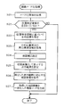
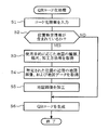
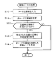
- FIG. 2 is a diagram showing a flow of image coding processing by the information code generation device
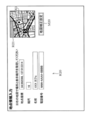
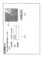
- FIG. 3 is a diagram illustrating an example of a screen for inputting point information in the situation A.
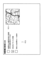
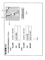
- FIG. 4 is a diagram 1 showing an example of an input screen for map correction setting in the situation A
- FIG. 5 is a second diagram illustrating an example of an input screen for map correction setting in the situation A.
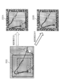
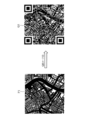
- FIG. 6 is a diagram illustrating an example of an information code generated in the situation A together with a reference example.
- FIG. 1 is a diagram schematically illustrating a configuration of an information code generation device according to an embodiment of the present disclosure.
- FIG. 2 is a diagram showing a flow of image coding processing by the information code generation device
- FIG. 3 is a diagram illustrating an example of a screen for inputting point information in the situation A.
- FIG. 4 is a diagram 1 showing
- FIG. 7 is a diagram showing an example of an input screen for point information in the situation B.
- FIG. 8 is a diagram showing an example of an input screen for map correction setting in situation B.
- FIG. 9 is a diagram illustrating an example of an information code generated in the situation B.
- FIG. 10 is a diagram illustrating an example of a screen for inputting point information in the situation C.
- FIG. 11 is a diagram illustrating an example of an input screen for map correction setting in situation C.
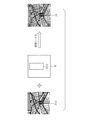
- FIG. 12 is a diagram illustrating an example of an information code generated in the situation C together with a reference example.
- FIG. 13 is a diagram illustrating an example of an input screen for point information in the situation D.
- FIG. 14 is a first diagram illustrating an example of an input screen for map correction setting in situation D.
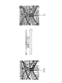
- FIG. 15 is a diagram illustrating an example of an information code generated in the situation D together with a reference example.
- FIG. 16 is a diagram schematically illustrating an electrical configuration of the information code generation device according to the first reference example of the present disclosure
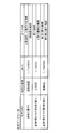
- FIG. 17 is a diagram illustrating an example of setting data registered in the setting DB.
- FIG. 18 is a diagram showing the flow of information coding processing.
- FIG. 19 is a diagram schematically showing an example when the map image before processing is information-coded.
- FIG. 20 is a diagram schematically showing an example when the map image after processing is information-coded.
- FIG. 21 is a diagram schematically illustrating an electrical configuration of an information code generation device according to a second reference example of the present disclosure;
- FIG. 22A is a diagram schematically illustrating an example of an information code generated when information coding is performed without setting a non-coding area
- FIG. 22B is a diagram schematically illustrating an example of an information code generated when an uncoded area is set
- FIG. 23 is a diagram showing the flow of information coding processing
- FIG. 24A is a diagram schematically illustrating another example (part 1) of integrating images
- FIG. 24B is a diagram schematically illustrating another example (part 2) in which images are integrated.
- the information code generation device 30 includes a control unit 31, a database (hereinafter referred to as DB (Data Base) 32), a UI (User Interface) unit 33, and the like.
- the information code generation device 30 of this embodiment is constructed as a so-called server.
- the information code generation device 30 can be connected to an input device such as a keyboard and a mouse and a display device such as a display. Therefore, although the information code generation described later can be performed independently on the information code generation device 30 side, the UI unit 33 (corresponding to the operation input unit) is configured as a WEB interface, for example, so that the user terminal 40 It can also be done over a network.
- the control unit 31 is configured by a computer having a CPU, a ROM, a RAM, and the like (not shown), and controls the entire information code generation device 30.
- the control unit 31 is provided with a setting unit 34 and an information code generation unit 35.
- the setting unit 34 and the information code generating unit 35 are configured by software by a computer program executed by the control unit 31.
- the setting unit 34 determines whether or not position specifying information capable of specifying a position is included in the coded information input to generate the information code, and based on the position specifying information.
- the target position is specified
- the environment information which is information about the surrounding environment of the specified target position, is acquired from the database, and the center position and / or scale when displaying as a map image based on the target position and the acquired environment information
- the display range displayed as a map image is set by adjusting.
- the environmental information includes POI information that can specify a POI (Point Of Interest) around the target position and terrain information that can specify the topography around the target position.
- POI Point Of Interest
- the information code generation unit 35 acquires a map image of the display range set by the setting unit 34 from the DB 32 and generates an information code in which the acquired map images are integrated.
- the information code integrated with the map image means that the user can visually grasp that the generated information code is a map when the user sees the generated information code, and the target position described above based on the displayed map image. It is an information code that can be visually grasped.
- the DB 32 stores map data for displaying a map image.
- map data various data for displaying a map image, such as names and telephone numbers of roads, rivers, stations, railway tracks, facilities, etc., are registered.
- map data for example, data that can specify a position (coordinates) such as longitude, latitude, or map code, setting data for changing display contents when the scale is changed, and the like are also registered.
- the DB 32 does not necessarily have to be built in the information code generation device 30 and may be configured to cooperate with an external database.
- the image coding process is a computer program executed by the control unit 31.
- the information code generating device 30 executes the image coding process shown in FIG. 2, and first obtains coded information (S1). At this time, the information code generation device 30 codes the point information (corresponding to the position specifying information) related to the point (corresponding to the target position) provided as the information code input from the point information input screen illustrated in FIG. 3, for example. Acquired as conversion information.
- the information code is generated independently by the information code generation device 30 (that is, the server) is described as an example, but the configuration may be such that the encoded information transmitted from the user terminal 36 is acquired.
- a point information input area R20 for example, point coordinates (for example, longitude and latitude), scale, name (facility name, etc.), telephone number, and the like of the target position.
- a numerical value can be directly input, but a map image having a size based on the current position, past history, etc. is displayed in the map display area R21 as an initial state. It is good also as a structure which substitutes the latitude and longitude of the position to a point coordinate by designating arbitrary upper positions.
- the point coordinates are information that can directly specify the target position.
- names and telephone numbers are registered in the map data for those that are open to the public, they can be information that can indirectly specify the target position. That is, these point coordinates, name (name), telephone number, etc. can be handled as position specifying information. Note that names and telephone numbers that are not disclosed, or names and telephone numbers that are not registered in the map data are not treated as position specifying information.
- a target position mark K1 is displayed at a position corresponding to the point coordinates input by the code creator or designated from the map image.
- the information code generation device 30 determines whether or not the position specifying information is included in the coded information (S21). When the position specifying information is not included (S21: NO) ), The process is terminated. On the other hand, when the position specifying information is included (S21: YES), the information code generating device 30 specifies the target position based on the position specifying information (S22), and acquires environment information around the target position. (S23).
- the information code generating device 30 performs map correction setting based on the target position and the environment information (S24).
- This map correction setting sets conditions for adjusting the display range to be displayed as a map image.
- the code creator can switch the operation screen to the map correction setting screen shown in FIG. 4 by operating the transition button M20 shown in FIG. Then, the code creator inputs the map correction setting from the map correction setting screen.
- the map correction setting for example, the following three modes of “not map correction”, “set the map center by yourself”, and “center the nearest point” can be set.
- the scale of the map image is set as “scale” in FIG.
- the scale may be changeable as the map correction setting.
- the map correction setting indicates that “set the map center by yourself” is selected, and the code creator specifies the center position of the map image (shown as the map center in FIG. 4). ing. Although a numerical value may be input, a map center is designated by specifying an arbitrary position on the map image displayed in the map display area R21 or by dragging and moving the map image. Also good.
- the position of the POI around the target position specified based on the environment information as shown in FIG. (Positions indicated by symbols A, B, C, and E) are displayed on the map image, and a selection field for selecting which POI to be the central position is displayed in the selection area R22.
- a POI that exists in the vicinity of the target position and is relatively easy for anyone to understand is selected in the size set by the “scale” in FIG.
- this POI for example, “A bus stop” (bus stop), “B market” (store), “C station” (station), “D tower” (TV tower, radio tower, etc.), “E bus stop” ( Bus stop (different from “A”), “F maeket” (store, different from “B”), etc.
- the information code generation device 30 uses the station nearest to the target position (the position indicated by the symbol C on the map image) as the center position of the map image. Will choose. That is, the information code generation device 30 selects one or more POIs to be displayed on the map image from the POIs specified by the POI information, and sets a range including the target position and the selected POI as a display range.
- the information code generating device 30 sets a display range to be displayed as a map image based on the target position, the environment information, and the map correction setting (S25).
- the display range finally set is substantially the range of the map image displayed on the point information input screen shown in FIG. 3 or the map correction setting screen shown in FIG. 4 or FIG. It is the same as the range of the map image. Therefore, the code creator can confirm the map image finally displayed on the point information input screen or the map correction setting screen.
- the information code generation device 30 acquires a map image of the set display range from the DB 32 (S26), and generates an information code in which the acquired map image is integrated (S27). More specifically, as shown in FIG. 6, the information code generation device 30 generates an information code in which map images within a display range set as a range including the target position are integrated. Note that. In the case of FIG. 6, the map image P20 in a somewhat wide range is illustrated for comparison.
- a range W1 indicated by a dotted line as a reference example and a range W2 indicated by a solid line as an example are shown.
- the range W ⁇ b> 1 is a display range when the map is not corrected around the target position, for example, when “Do not perform map correction” is selected in FIG. 4.
- the range W2 is a display range in the case where there is a map correction centered on a position different from the target position, for example, when “C station” is selected in FIG.
- the information code generation device 30 when the range W1 is set as the display range, the information code generation device 30 generates the information code J20A whose target position is the center of the map image. On the other hand, when the range W2 is set as the display range, the information code generating device 30 generates an information code J20B having a position different from the target position, in this case, the nearest station of the target position being the center of the map image. To do.
- the information code generating device 30 adjusts based on the target position and the environment information so that the POI (in this case, the station) existing at a position different from the target position becomes the center position. It is carried out. That is, one or more POIs to be displayed on the map image are selected from the POIs specified by the POI information, and a range including the target position and the selected POI is set as the display range.
- the user who sees the information code J20B can grasp that the target position is in the vicinity of the station C.
- the display range so that a station that is easy for everyone to use as a landmark is at the center of the map image, where the target position is for the user who saw the information code, and how it is from the station It can be presented in an easy-to-understand manner whether the target position is reached if it moves.
- the POI specified by the POI information includes a preset specific type of POI, for example, when a station is set as the specific type of POI, the station closest to the destination position is selected. You may set to the center of a display range. Thereby, when there are a plurality of specific types of POI such as a plurality of stations in the vicinity, an information code can be generated more easily.
- a range including all the specific types of POIs may be set as the display range. For example, when there are a plurality of bus stops and all the bus stops are at the same distance, all the bus stops may be displayed. Thereby, many choices can be provided to the user.
- the POI type is different between the case where the nearest POI among the specific types of POIs is centered and the case where all of the specific types of POIs are displayed, and the closest one is displayed while displaying all of the POIs of a certain type
- a certain kind of POI may be set at the center position of the map image.
- FIG. 6 shows an example in which the entire map image is information-coded, that is, an example of an information code in which the map image is superimposed, but information that does not superimpose part or all of the map image as in form C described later.
- a code may be generated, a map image may be simplified as in a first reference example described later, or an information code may be generated by providing a non-coded area as in a second reference example described later.
- both the center position and the scale may be changed, or only the center position or only the scale may be changed.
- the forms B to D described later are described later.
- the code creator specified the center position of the map image ("Set the map center by yourself” shown in FIG. 4), but by specifying the scale and the amount of deviation from the target position Designation of the center position, designation of the center position and / or scale by inputting position information that is different from the target position or position information that can identify the object position, for example, relatively, like a map image P20 shown in FIG.
- a large map image may be displayed, and the code creator may directly input the designation of the display range by the code creator, that is, the code creator may designate the display range directly with a rectangular frame or the like.
- the designation of the amount of deviation from the target position is a designation method in which a relative position (for example, coordinate difference, distance or direction) from the target position is designated, and that is used as the map center.
- a relative position for example, coordinate difference, distance or direction
- one or more coordinates or position information other than the target position may be specified, and the map center and / or scale may be adjusted so that the target position and the specified target position are included.
- the target position includes not only the POI different from the target position but also those set purely with coordinates or the like.
- Such a designation method is useful, for example, when displaying a lake or the like around the target position on a map image.
- Form B is an example in which a plurality of pieces of point information of, for example, points 1 to 4 are input from the point information input screen as shown in FIG.
- the point 4 has deviated from the map image displayed in the map display area R21. Therefore, if the information code is generated as it is, the point 4 is not displayed on the map image, and the user cannot visually grasp the position of the point 4.
- the information code generation device 30 sets the range including the point 4 as the display range of the map image based on the map correction setting.
- the map correction setting the following “map and scale are set by yourself”, “place all points in a balanced manner”, “between specified points” Three modes of “display route” can be set.
- All points in good balance The center position and / or scale are changed so that all target positions are displayed in the map image, and each target position is automatically arranged in a balanced manner in the map image.
- Display route between specified points When there are multiple target positions and there is a movement route between each of the target positions, a range including the movement route is set as a display range.
- the map correction setting shows a state where “place all points in a balanced manner” is selected, and by changing the scale and the center position with respect to the map image of FIG. Shows a state in which the display range is set so as to enter the map image. Specifically, as shown in FIG. 9, the display position indicated by the broken line in the map image P21 in the initial state, the position D (the position “4” in FIG. 8) is displayed on the map image. Although not performed, the range indicated by the solid line in the map image P21 is set as the display range by the map correction setting.
- the information code generation device 30 acquires a map image of the set display range, and generates an information code that integrates the acquired map image.
- all target positions positions indicated by symbols A to D in FIG. 9 are displayed in the information code J21. Therefore, even when a plurality of target positions are set, it is possible to easily show where the target position is to the code creator who has seen the information code.
- a moving route exists (or set by the code creator) such as point 1 ⁇ point 2 ⁇ point 3 ⁇ point 4, the moving route is also included as in form C described later.
- the display range may be set as described above.
- the number of input target positions is not limited to the above example.
- Form C is an example in which a plurality of pieces of point information of, for example, point 1 and point 2 are input from the point information input screen as shown in FIG. Between these two points 1 and 2, there is a route X1 (a moving route from point 1 to point 2). Although not shown in the figure, the route X1 is generated by setting whether or not to create a route between points and by the operation of the code creator.
- the route X1 has deviated from the map image at the initial scale shown in the map display area R21. Therefore, if the information code is generated as it is, it is impossible to grasp how long the path X1 is.
- the information code generation device 30 sets the range including the route X1 as the display range of the map image based on the map correction setting. Specifically, the information code generating device 30, as shown in FIG. 11 as the map correction setting, selects “display route between designated points” as shown in the map image in the map display area R21. By changing the center position and / or scale, it is possible to display all of the route X1 on the map image.
- the information code generation device 30 acquires a map image of the set display range, and generates an information code that integrates the acquired map image.
- the information code J21A is generated without map correction, the distance between Start (in this case, point 1 and departure place) and Goal (in this case, point 2 and destination).
- the information code J21B is generated with map correction, the route X1 between Start and Goal is displayed.
- the range including the movement path is set as the display range. It may be set. For example, it is conceivable to set the starting point of the hiking course as the target position, set the nearest station as the target position, and set the range including the route from the nearest station to the starting point as the display range. Thereby, for example, the route to the starting point of the hiking course can be easily presented to participants from a distance.
- Form D When a display range is set based on terrain information. See FIGS. 13 to 15> Form D is an example in which, for example, point information of the FF lighthouse is input from the point information input screen as shown in FIG. Since the lighthouse exists near the coast, it is assumed that the sea (corresponding to a specific type of topography in the present embodiment) is spread around the lighthouse. Therefore, although there is a difference depending on the actual landform, in the map image when the FF lighthouse is the center, as shown in the map display area R21, for example, the sea may occupy most of the map image.
- the position of the FF lighthouse becomes easier to understand by reducing the sea area and increasing the land area corresponding to the route to the FF lighthouse.
- the terrain information which is information that can specify the type of terrain, is registered in the map data stored in the DB 32, so the terrain information can be acquired as environment information.
- the information code generation device 30 uses the display conditions set for the specific type of terrain. Therefore, the display range is set.
- “land” and “sea” are set as specific types of terrain, for example, as shown in FIG.
- other topography such as a mountain, a forest, a lake, etc.
- “increase the area of the designated landform” is set as the display condition.
- the information code generating device 30 adjusts the center position and / or scale of the map image so as to increase the area of the land in the map image when “land” is designated as the terrain as shown in FIG. 14, for example. To do.
- the map image shown in FIG. 14 has a reduced area of the sea, which is a specific type of terrain, compared to the map image shown in FIG.
- the information code generation device 30 generates an information code based on the map image of the set display range.
- an information code J23A in which a map image having a relatively large sea area is integrated is generated.
- the position of the FF lighthouse can be presented in an easy-to-understand manner.
- one display condition is exemplified in the form D
- a plurality of display conditions may be selectable or simultaneously usable.
- display conditions such as minimizing the area where a specific type of terrain is displayed or reducing the area where the specific type of terrain is displayed to a predetermined ratio or less may be employed.
- conditions such as surrounding POI included in the display range, nearest POI included in the display range, and a plurality of target positions included in the display range may be combined.
- the scale is increased (that is, the map is enlarged), it is possible to display only the land. However, in that case, the position cannot be grasped, so when setting display conditions that minimize the area or keep it below a predetermined ratio, set a certain limit on the scale. Is desirable. For example, there may be a condition such as a scale set at the time of inputting point information such that the area of the sea is minimized at the initial value, a condition that permits adjustment of the scale for ⁇ 1 step from the initial value, and the like.
- the information code generation device 30 specifies the target position based on the position specifying information included in the coded information for generating the information code, and is environment information that is information on the surrounding environment of the specified target position. Is set from the DB 32, and a setting unit 34 that sets a display range to be displayed as a map image by adjusting a center position and / or a scale when displaying as a map image based on the target position and the acquired environment information; An information code generation unit 35 that acquires a map image of the display range set by the setting unit 34 from the DB 32 and generates an information code that integrates the acquired map image.
- the target position and the surrounding environment of the target position are displayed in the information code generated by the information code generating device 30.
- the user can grasp the positional relationship between the target position and the buildings or the like existing in the vicinity thereof, and can grasp the vicinity of the target position. Therefore, when generating an information code integrated with a map image, it is possible to easily show where the target position is to the user who viewed the information code.
- a process for specifying the target position based on the position specifying information included in the coded information for generating the information code, and environment information that is information related to the surrounding environment of the specified target position are acquired from the DB 32, A process for setting a display range to be displayed as a map image by adjusting the center position and / or scale when displaying as a map image based on the target position and the acquired environment information, and a map image of the set display range Can be obtained from the DB 32 and an information code generation program including the process of generating an information code in which the acquired map image is integrated can be executed to obtain the same effects as those of the information code generation device 30. .
- the environmental information includes POI information that can identify the POI existing around the target position. Then, the information code generation device 30 selects one or more POIs to be displayed on the map image from the POIs specified by the POI information, and sets a range including the target position and the selected POI as a display range. As a result, a POI near the target position, such as a station or department store, can be displayed in the map image as a landmark, and the target position can be more easily grasped. In this case, it is considered that the position can be easily understood by selecting a large facility or a famous facility.
- the information code generation device 30 sets the specific type of POI closest to the target position as the center position. Set the display range. Thereby, for example, when a plurality of POIs are registered in the DB 32 and when all of them are displayed, map images are crowded, an appropriate map image can be selected. This is significant when it is desired to present a plurality of pieces of information (target position and POI) with a relatively small size like an information code.
- the information code generation device 30 sets a display range so as to include all the specific types of POIs. Also good. In this case, the type may be changed between selecting the nearest POI and including all POIs. For example, it is conceivable to set a display range including one nearest station and all bus stops. As a result, more information can be presented to the user, such as an increase in route options when the user moves, for example.
- the information code generating device 30 sets a range including all the target positions as a display range. As a result, it is possible to easily present all the information that the information code producer wants to present.
- the information code generating apparatus 30 sets a range including the path as a display range. Thereby, it is possible to visually present not only the target position but also its moving route. Further, the content of the provided information can be grasped to some extent without reading the information code.
- the information code generation device 30 specifies a target position different from the target position or position information that can specify the target position, and if a path exists between the target position and the target position, a range including the path Is set as the display range.
- the closest POI described above may be set as the target position. Thereby, it is possible to visually present not only the target position but also its moving route.
- the information code generation device 30 acquires environmental information including terrain information, which is information that can specify the type of terrain, and includes a specific type of terrain that is preset in the type of terrain specified by the terrain information. If so, the display range is set according to the display conditions set for the specific type of terrain. Thereby, for example, the area of the sea in the map image can be reduced as described above. The map image area of the information code assumed to be generated with a relatively small size can be effectively used.
- terrain information is information that can specify the type of terrain, and includes a specific type of terrain that is preset in the type of terrain specified by the terrain information. If so, the display range is set according to the display conditions set for the specific type of terrain. Thereby, for example, the area of the sea in the map image can be reduced as described above.
- the map image area of the information code assumed to be generated with a relatively small size can be effectively used.
- the information code generation device 30 can accept the operation of the code creator, specifies the center position and / or scale of the map image, specifies the center position by specifying the amount of deviation from the target position, and the target position.
- the display range according to at least one of the target position different from the above, or the center position and / or scale designation by inputting position information that can identify the target position, and the direct designation of the display range Set. Thereby, a display range can be specified finely and a map image in line with the intention of the code producer can be displayed.
- the setting unit 34 and the information code generation unit 35 may be provided as an information code generation program product stored in a computer-readable persistent and tangible storage medium that includes instructions executed by a computer. Good.
- the processing performed by the setting unit 34 and the information code generation unit 35 may be provided as an information code generation method.
- the information code generating device 1 includes a control unit 10, an input unit 11, a display unit 12, an external I / F 13, an image database 14 (hereinafter referred to as an image DB), and a setting database 15 (hereinafter referred to as a setting). (Referred to as DB).
- the information code generation device 1 of this embodiment is configured by a so-called personal computer. Therefore, the control unit 10 is configured by a CPU of a personal computer, the input unit 11 is configured by a keyboard and a mouse, and the display unit 12 is configured by a display.
- coded information for generating a QR code (information code) is input from the input unit 11, and the generated QR code is displayed on the display unit 12.
- the external I / F 13 is configured by, for example, a network interface or a memory card interface.
- the control unit 10 includes a position specifying unit 16, an image acquisition unit 17, a setting acquisition unit 18, an image processing unit 19, and a QR code generation unit 20 (corresponding to an information code generation unit).
- the position specifying unit 16 determines whether or not the position specifying information is included in the coded information for generating the QR code, and when the position specifying information is included. Identify the location.
- the image acquisition unit 17 acquires, from the image DB 14, an image that can visually present the type of information provided by the generated QR code, based on the coded information for generating the QR code. In the case of this embodiment, the image acquisition unit 17 acquires a map image including the vicinity of the position specified by the position specifying unit 16 and map data corresponding to the map image from the image DB 14.
- the setting acquisition unit 18 acquires the setting for processing the map image from the setting data stored in the setting DB 15. Based on the map data acquired by the image acquisition unit 17, the image processing unit 19 processes a map image for integration with the QR code (in this embodiment, for superimposition).
- the image processing unit 19 processes the map image based on the combination of settings registered in the setting data according to the purpose for displaying the QR code.
- the QR code generation unit 20 generates a QR code based on the coded information.
- the QR code generation unit 20 is an information code generation unit that generates a QR code on which the acquired image is superimposed. Function.
- the position specifying unit 16, the image acquisition unit 17, the setting acquisition unit 18, the image processing unit 19, and the QR code generation unit 20 are realized in software by a program executed by the control unit 10.
- the image DB 14 and the setting DB 15 are composed of a recording medium such as a hard disk device.
- the image DB 14 and the setting DB 15 are shown separately, but in this embodiment, the image DB 14 and the setting DB 15 are configured from a single hard disk.
- the image DB 14 stores map data in this embodiment.
- map data data for displaying a map image including the vicinity of a certain position, such as roads, rivers, stations, railroad tracks, various facilities, and the like are registered.
- the map image is naturally changed. That is, the map image acquired by the above-described image acquisition unit 17 is not fixed and changes each time.
- This map image corresponds to an image that can visually present the type of information provided by the generated QR code.
- the map image can be displayed in color, and the QR code is displayed in color when superimposed on the QR code as will be described later. It may be a black and white display.
- the information provided by the QR code is information related to the position.
- the information regarding the position is provided as information for specifying the position of the event venue, for example, in an information magazine in which event information, leisure information, and the like are posted.
- by linking with a navigation application it is possible to guide to a position read from a QR code, that is, a destination. That is, only by looking at the QR code, a person can visually grasp that the positional information is provided by the QR code.
- the information code generation device 1 processes the map image by the above-described image processing unit 19 in order to make the map easy to see, that is, to easily grasp the position.
- various settings for processing the map image are registered in the setting DB 15. In the present embodiment, the following method is set in the setting data.
- Settings for emphasizing specific data included in map data When displaying map images based on map data, highlight specific data such as major roads, railways, rivers, administrative division boundaries, etc. Settings for. For example, the road can be highlighted by displaying the main road thickly, changing the display color, or clarifying the outline. It should be noted that whether or not the road is a main road may be determined based on a determination criterion such as a road width or a national road based on the map data. In the present embodiment, those determination criteria are also registered in the setting data.
- ⁇ Setting when displaying a mark on a map image When displaying a map image based on map data, a setting is made to make it easier to recognize notable information by placing target symbols on the map image. For example, by displaying a destination mark or the like on a map image, it is possible to grasp where the destination is.
- Settings for simplifying specific data included in map data Settings for simplifying and displaying complex terrain and facility appearance when displaying map images based on map data. For example, by simplifying complicated terrain such as coastlines and hills, for example, it is possible to display in a state where it is easy to grasp while grasping the shape.
- [Setting when changing the scale of the displayed map image Setting for changing the display range when displaying the map image based on the map data. For example, 1/5000 is set when a map image of an urban area is displayed, and 1 / 100,000 is set when a map image including a highway is displayed.
- [Type of map to be displayed Setting of map data to be the basis of the map image to be displayed such as road map, route map, city map, etc.
- these settings are registered in various combinations depending on the purpose of use for displaying the QR code.
- the purpose of use of the QR code is “vehicle guidance”
- the map type is “road map”
- the scale is “1 / 100,000”
- the processing method is “ Combinations such as “emphasize main roads and main rivers” and “delete narrow streets” are registered.
- the purpose of using the QR code is “walking from the nearest station”
- the map type is “city map”
- the scale is “1/5000”
- the processing method is “emphasize station”, “main station” Combinations such as “emphasize building” are registered.
- the purpose of using the QR code is “Train guidance to the nearest station”, the map type is “Route”, the scale is “1/50000”, the processing method is “Highlight nearest station”, “Transfer” Combinations such as “emphasize station” are registered. Note that these setting data are merely examples, and it is needless to say that combinations other than those described above may be used.
- the information code generation device 1 having such a configuration generates an information code that can visually grasp the type of information to be provided as follows. Note that a method for generating the QR code itself and a method for colorizing the QR code are well known, and thus the description thereof is omitted. Each process is performed by the position specifying unit 16, the image acquiring unit 17, the setting acquiring unit 18, the image processing unit 19, the QR code generating unit 20, and the like. For simplicity of explanation, an information code generation is performed. The apparatus 1 will be mainly described.
- the information code generating device 1 determines whether or not position specifying information is included (S2).
- the position specifying information is information that can specify the position among the information included in the coded information. For example, latitude and longitude, address, postal code, telephone number, area mesh code (JISJX 0410) It is information that can specify a point directly or indirectly. This determination is performed by the position specifying unit 16. Further, the process of step S2 corresponds to a position specifying process.
- step S6 corresponds to an information code generation process.
- the generated QR code is displayed in a general light and dark pattern. For this reason, it is difficult for a person to grasp the type of information provided only by looking at the QR code.
- the information code generation device 1 determines that the position specifying information is included (S1: YES)
- the information code generation device 1 extracts the purpose of use from the coded information, and the map type, scale, Settings such as a processing method are acquired (S3).
- the process in step S3 is a setting acquisition process for acquiring settings from the setting data stored in the setting DB 15.
- the setting acquisition is performed by the setting acquisition unit 18.
- the information code generating device 1 acquires a map image near the specified position and map data for displaying the map image from the image DB 14 (S4).
- the process in step S4 corresponds to an image acquisition process.
- the acquisition of this map image is performed by the image acquisition unit 17.
- the acquired map image is an image in the vicinity of the specified position, and the surrounding roads and facilities including the position are displayed. Specifically, various kinds of information are included like a map image P1 shown in FIG. For this reason, if the map image is directly superimposed on the QR code, it is conceivable that the light and dark pattern overlaps with the map, making it difficult to see like the QR code Q1.
- the information code generation device 1 processes the map image based on the purpose of use and the setting acquired in step S3 (S5). Specifically, for example, when the purpose of use is the above-mentioned “vehioned “vehicle guidance”, the information code generation device 1 uses a processing method of “emphasizing main roads and main rivers” and “deleting narrow streets” as a map. Process the image. In addition, main roads, main rivers, narrow streets, and the like can be identified from map data. As a result, the map image P1 shown in FIG. 19 emphasizes the main road and the narrow street is deleted, like the map image P2 shown in FIG.
- the process of step S5 is a map processing process that processes a map image based on the setting acquired by the setting acquisition unit 18. The map image is processed by the image processing unit 19.
- the information code generation device 1 generates a QR code using the processed map image (S6).
- the QR code Q2 shown in FIG. 20 can be a map even if it is superimposed on a light and dark pattern, and a QR code that can visually grasp the position of the map can be generated. it can.
- the information code generation device 1 generates an image that can visually present the type of information provided by the generated information code (in this embodiment, a QR code) based on the coded information for generating the QR code. And a QR code in which the acquired images are integrated (superimposed in this embodiment) is generated. Thereby, the person can grasp
- a QR code in this embodiment, a QR code
- the information code generating device 1 determines whether or not position specifying information is included in the coded information, specifies a position when the position specifying information is included, and a map including the vicinity of the specified position An image is acquired and a QR code on which the map image is superimposed is generated. As a result, it is possible to visually grasp that the information provided by the QR code is the position, and it is possible to grasp the position by looking at the QR code. Can be provided.
- the information code generation device 1 acquires map data corresponding to a map image including the vicinity of the specified position, and processes the map image based on the acquired map data. Since the map data includes information such as roads and rivers, the display mode of roads and rivers can be changed based on the map data. For example, the map can be easily seen by performing processing such as emphasizing the main road. Therefore, it is possible to grasp where the destination is by simply looking at the QR code.
- the information code generation device 1 acquires setting data in which settings for processing a map image are registered from the setting DB 15, and processes the map image based on the acquired settings. Thereby, a map image can be processed according to the main purpose of use. In addition, since settings such as the processing method are registered in advance, the amount of work for the creator can be reduced, and convenience can be improved.
- the setting data includes settings for emphasizing specific data included in map data, settings for blurring specific data included in map data, settings for displaying landmarks on map images, and map data.
- Settings for simplifying specific data included, settings for changing the scale of a map image to be displayed, and settings such as the type of map to be displayed are registered in advance. For this reason, it is possible to easily determine what processing should be performed when generating the QR code.
- each setting described above is registered according to the purpose of use for displaying the QR code.
- the information code generation device 1 processes the map image based on a combination of settings corresponding to the purpose of use for displaying the QR code. This makes it possible to use a large scale to emphasize main roads for notifying passengers by car from a distance, or a small scale to emphasize railways for guidance from stations to shops. Processing according to the purpose can be performed. Therefore, the work amount of the creator of the QR code can be reduced, and convenience can be improved.
- An image for acquiring, from the database, an image that can visually present the type of information provided by the generated information code to the control unit 10 of the information code generation device 1 based on the coded information for generating the information code Performs an acquisition process and an information code generation process that generates an information code based on the encoded information, and generates an information code on which the acquired image is superimposed when the image is acquired by the image acquisition process By doing so, it is possible to obtain the effects as described above, for example, it is possible to generate an information code capable of visually grasping the type of information to be provided.
- the position specifying process for specifying the position based on the position specifying information is executed, and the map image including the vicinity of the specified position is acquired in the image acquisition process, so that the information provided by the information code is the position. It is possible to generate an information code capable of visually grasping a certain thing and grasping a position by looking at the information code.
- the information code generation device 1 of the present exemplary embodiment includes a non-coded area setting unit 21 in addition to the configuration of the first reference example.
- the non-coding area setting unit 21 sets a non-coding area that is an area that is not coded when the information code generation unit 22 generates an information code.
- the entire information code J1 integrated with the map image P10 is coded. It will be.
- the map image P10 is divided into, for example, a bright part and a dark part, the information included in the map image P10 may be difficult to see. That is, the information that could be presented in the map image P10 may be lost when it is coded and becomes the information code J1.
- information that can be read as “S” in the map image P10 is slightly difficult to see in the coded information code J1.
- the information code generation device 1 of the present embodiment generates an information code that can more easily present information and its type in the following manner.
- the information code generating device 1 executes the information coding process shown in FIG. 23.
- the coded information described in the first reference example is input (S10), the non-code is generated.
- a conversion area is set (S2). Since this non-coded area is an area that is not coded as described above, the creator of the information code must set the part containing the information to be presented to be the non-coded area. That's fine.
- the creator inputs four points within the range W, That is, the non-coding region R10 can be set by designating four vertices of a rectangle.
- a user interface may be used in which the original shape is registered in the setting DB 15 and the size of the original shape is changed to set the non-coded area.
- the information code generating device 1 determines whether or not the position specifying information is included in the coded information (S12).
- This position specifying information is the same information as described in the first reference example.
- the process in step S12 corresponds to a position specifying process.
- the process is terminated.
- the position specifying information is not included, as described in the first reference example, as a flow of generating an information code based only on the coded information without integrating (superimposing) the map images. Also good.
- step S4 corresponds to an image acquisition process.
- the information code generating device 1 generates an information code reflecting the set non-coded area, that is, an information code in which the non-coded area is not coded (S14). Specifically, as illustrated in FIG. 22B, the information code generation device 1 generates an information code J2 in which a region excluding the non-coding region R10 in the range W is encoded. Thereby, for example, the range where “S” is expressed in the map image is not coded, and the user who sees the generated information code can clearly see “S”.
- the information code generation device 1 includes the non-coding area setting unit 21 that sets a non-coding area that is an area where coding is not performed.
- An information code in which the area excluding the non-coded area set by the area setting unit 21 is coded is generated. That is, an image that can visually present the type of information and coded information are combined to achieve both visual recognition by the user and mechanical reading by a reading device or the like.
- the flow of the information encoding process shown in FIG. 23 may be changed as appropriate. For example, as described later, after acquiring a map image, the setting of the non-code area may be accepted while displaying the image. With such a processing flow, it is considered that the non-coding area can be set while viewing the acquired map image, so that the usability can be improved.
- point information is included in the coded information, it may be the information itself that the location or building specified by the point information is the information that you want to present. Of course, there are cases where a sufficient effect can be obtained by setting the non-coding region in the vicinity of the center of W.
- non-coded area is not limited to the quadrangle illustrated in FIG. 22B, but may be a polygon, a circle, a free hand area of the creator, or the like.
- a map image P10 may be acquired based on the input coded information, and a non-coded region R11 having the size of the map image P10 may be set.
- an information code J3 in which the periphery of the map image P10 is coded is generated.
- the entire width direction of the information code W may be set as a non-coded area.
- the image to be integrated is not limited to the map image P10, and may be, for example, a logo mark or a photograph of a product.
- the integrated image is not limited to the map image. That is, the type of information provided by the information code may be other than information related to the position. For example, you may make it integrate with the image which can present visually that it is a restaurant, a hotel, etc.
- the information code generating device 1 is configured by a single personal computer.
- the position specifying unit 16, the image acquiring unit 17, the setting acquiring unit 18, the image processing unit 19, and the QR code generating unit 20 are connected to a plurality of personal computers. It may be configured to be distributed among servers on the network. Further, the input device and the display device may be distributed, for example, the coded information is input to the information code generation device 1 by a creator's personal computer or smart phone.
- an information code generation system that installs the image DB 14 and the setting DB 15 on a server or the like on the network, transmits encoded information or the like from the information code generation device 1 side to the server side, and acquires an image selected on the server side. May be constructed. Further, the image DB 14 and the setting DB 15 may be provided on different servers.
Landscapes
- Engineering & Computer Science (AREA)
- Theoretical Computer Science (AREA)
- Physics & Mathematics (AREA)
- General Physics & Mathematics (AREA)
- Databases & Information Systems (AREA)
- Remote Sensing (AREA)
- Data Mining & Analysis (AREA)
- General Engineering & Computer Science (AREA)
- Instructional Devices (AREA)
- Navigation (AREA)
- Processing Or Creating Images (AREA)
Abstract
情報コード生成装置は、情報コードを生成するためのコード化情報に含まれている位置特定情報に基づいて目的位置を特定し、特定した目的位置の周辺環境に関する情報である環境情報をデータベースから取得し、目的位置と取得した環境情報とに基づいて、地図画像として表示する際の中心位置と縮尺のうち少なくとも1つを調整することにより地図画像として表示する表示範囲を設定する設定部(34)と、設定部(34)によって設定された表示範囲の地図画像をデータベース(32)から取得し、取得した地図画像を一体化した情報コードを生成する情報コード生成部(35)と、を備える。
Description
本出願は、2015年6月26日に出願された日本特許出願番号2015-128692号に基づくもので、ここにその記載内容を援用する。
本開示は、情報コードを生成する情報コード生成装置および情報コード生成プログラム製品に関する。
情報コードは、一般的に、読み取り装置により読み込むことを前提として生成されている。このため、その情報コードを見ただけでは、どのような情報が含まれているのかを人が視覚的に把握することは困難である。そのため、情報コードの周辺に説明文を記載したり、情報コードに社名等を重ねて表示したり、あるいは、例えば特許文献1のようにあらかじめデザインした画像を重ねて表示したりすることがある。
情報コードを生成するために入力されたコード化情報に位置を特定可能な情報(以下、位置特定情報と称する)が含まれている場合、その位置特定情報により特定される位置(以下、目的位置と称する)が含まれる地図画像を一体化した情報コードを生成することが考えられる。そのような地図画像を一体化した情報コードであれば、読み取り装置がなくても、目的位置を視覚的に提示することができるためである。
ところで、地図画像を一体化した情報コードを生成する場合、一般的には、目的位置を明示するために、目的位置を地図画像の中心に据えると考えられる。
しかしながら、たとえ目的位置が地図画像に明示されていたとしても、その目的位置を把握できない場合がある。例えば、目的位置周辺の地理に疎いユーザの場合、目的位置が明示されていたとしても、その周辺の地理が分からないために、結局は目的位置がどこであるのかを把握できないことがある。このように、情報コードを見たユーザに対して目的位置がどこであるかを分かり易く提示するためには、単に地図画像に目的位置を示すだけではなく、どのように示すかが重要となってくる。
本開示は上記事情に鑑みてなされたものであり、その目的は、地図画像を一体化した情報コードを生成する場合において、情報コードを見たユーザに対して目的位置がどこであるかを分かり易く提示することができる情報コードを生成する情報コード生成装置および情報コード生成プログラム製品を提供することにある。
本開示の一態様による情報コード生成装置は、位置特定情報に基づいて目的位置を特定し、特定した目的位置の周辺環境に関する情報である環境情報をデータベースから取得し、目的位置と取得した環境情報とに基づいて地図画像として表示する際の中心位置および/または縮尺を調整することにより地図画像として表示する表示範囲を設定する設定部と、設定部によって設定された表示範囲の地図画像をデータベースから取得し、取得した地図画像を一体化した情報コードを生成する情報コード生成部と、を備える。
上記装置によると、地図画像を一体化した情報コードを生成する場合において、情報コードを見たユーザに対して目的位置がどこであるかを分かり易く提示することができる。
本開示の他の態様による情報コード生成プログラム製品は、情報コードを生成するためのコード化情報に含まれている位置特定情報に基づいて目的位置を特定し、特定した目的位置の周辺環境に関する情報である環境情報を取得し、目的位置と取得した環境情報とに基づいて地図画像として表示する際の中心位置と縮尺のうち少なくとも1つを調整することにより地図画像として表示する表示範囲を設定し、設定された表示範囲の地図画像を取得し、取得した地図画像を一体化した情報コードを生成するためのコンピュータによって実施される命令を含み、コンピュータ読み取り可能な持続的且つ有形の記憶媒体に保管されている。
上記プログラム製品によると、地図画像を一体化した情報コードを生成する場合において、情報コードを見たユーザに対して目的位置がどこであるかを分かり易く提示することができる。
本開示についての上記目的およびその他の目的、特徴や利点は、添付の図面を参照しながら下記の詳細な記述により、より明確になる。その図面は、
図1は、本開示の一実施形態による情報コード生成装置の構成を模式的に示す図であり、
図2は、情報コード生成装置による画像コード化処理の流れを示す図であり、
図3は、状況Aにおける地点情報の入力画面の一例を示す図であり、
図4は、状況Aにおける地図補正設定の入力画面の一例を示す図その1であり、
図5は、状況Aにおける地図補正設定の入力画面の一例を示す図その2であり、
図6は、状況Aにおいて生成される情報コードの一例を参考例とともに示す図であり、
図7は、状況Bにおける地点情報の入力画面の一例を示す図であり、
図8は、状況Bにおける地図補正設定の入力画面の一例を示す図であり、
図9は、状況Bにおいて生成される情報コードの一例を示す図であり、
図10は、状況Cにおける地点情報の入力画面の一例を示す図であり、
図11は、状況Cにおける地図補正設定の入力画面の一例を示す図であり、
図12は、状況Cにおいて生成される情報コードの一例を参考例とともに示す図であり、
図13は、状況Dにおける地点情報の入力画面の一例を示す図であり、
図14は、状況Dにおける地図補正設定の入力画面の一例を示す図その1であり、
図15は、状況Dにおいて生成される情報コードの一例を参考例とともに示す図であり、
図16は、本開示の第1参考例の情報コード生成装置の電気的構成を模式的に示す図であり、
図17は、設定DBに登録されている設定データの一例を示す図であり、
図18は、情報コード化処理の流れを示す図であり、
図19は、加工前の地図画像を情報コード化した際の一例を模式的に示す図であり、
図20は、加工後の地図画像を情報コード化した際の一例を模式的に示す図であり、
図21は、本開示の第2参考例の情報コード生成装置の電気的構成を模式的に示す図であり、
図22Aは、非コード化領域を設定せずに情報コード化した場合に生成される情報コードの例を模式的に示す図であり、
図22Bは、非コード化領域を設定した場合に生成される情報コードの例を模式的に示す図であり、
図23は、情報コード化処理の流れを示す図であり、
図24Aは、画像を一体化する他の例(その1)を模式的に示す図であり、
図24Bは、画像を一体化する他の例(その2)を模式的に示す図である。
以下、本開示の実施形態について、図1から図15を参照しながら説明する。
図1に示すように、情報コード生成装置30は、制御部31、データベース(以下、DB(Data Base)32と称する)、UI(User Interface)部33等を備えている。本実施形態の情報コード生成装置30は、いわゆるサーバとして構築されている。この情報コード生成装置30は、図示は省略するが、キーボードやマウス等の入力機器やディスプレイ等の表示機器を接続することができる。そのため、後述する情報コードの生成は、情報コード生成装置30側で単独で行うこともできるが、UI部33(操作入力部に相当する)を例えばWEBインターフェースとして構成することにより、ユーザ端末40からネットワーク越しに行うこともできる。
制御部31は、図示しないCPU、ROMおよびRAM等を有するコンピュータで構成されており、情報コード生成装置30全体を制御する。また、制御部31には、設定部34および情報コード生成部35が設けられている。これら設定部34および情報コード生成部35は、本実施形態では、制御部31で実行されるコンピュータプログラムによってソフトウェア的に構成されている。
設定部34は、詳細は後述するが、情報コードを生成するために入力されたコード化情報に位置を特定可能な位置特定情報が含まれているか否かを判定し、位置特定情報に基づいて目的位置を特定し、特定した目的位置の周辺環境に関する情報である環境情報をデータベースから取得し、目的位置と取得した環境情報とに基づいて地図画像として表示する際の中心位置および/または縮尺を調整することにより地図画像として表示する表示範囲を設定する。ここで、環境情報とは、目的位置の周辺のPOI(Point Of Interest)を特定可能なPOI情報、目的位置の周辺の地形を特定可能な地形情報を含んでいる。
情報コード生成部35は、詳細は後述するが、設定部34によって設定された表示範囲の地図画像をDB32から取得し、取得した地図画像を一体化した情報コードを生成する。なお、地図画像を一体化した情報コードとは、生成された情報コードをユーザが見た場合に、地図であることが視覚的に把握でき、また、表示されている地図画像によって上記した目的位置を視覚的に把握できる情報コードである。
DB32は、地図画像を表示するための地図データを記憶している。この地図データには、例えば道路、河川、駅、線路、施設等の名称や電話番号など、地図画像を表示するための各種のデータが登録されている。また、地図データには、例えば経度や緯度あるいはマップコードなどの位置(座標)を特定可能なデータや、縮尺を変更した際に表示内容を変更するための設定データ等も登録されている。なお、DB32は、必ずしも情報コード生成装置30に内蔵されている必要はなく、外部のデータベースと連携する構成であってもよい。
次に、上記した構成の作用について説明する。
なお、以下では、情報コードを生成する複数の形態(形態A~形態D)について説明するが、説明の簡略化のために、まず、形態Aにおいて図2に示す画像コード化処理の流れを説明し、形態B~形態Dについては、画像コード化処理の詳細な説明は省略する。なお、画像コード化処理は、制御部31によって実行されるコンピュータプログラムである。
<形態A:目的位置が1つの場合。図2~図6参照>
情報コード生成装置30は、図2に示す画像コード化処理を実行し、まず、コード化情報を取得する(S1)。このとき、情報コード生成装置30は、例えば図3に例示する地点情報入力画面から入力された情報コードとして提供する地点(目的位置に相当する)に関する地点情報(位置特定情報に相当する)をコード化情報として取得する。なお、以下では情報コード生成装置30(つまりサーバ)で単独で情報コードを生成する場合を例として説明しているが、ユーザ端末36から送信されるコード化情報を取得するような構成でもよい。
情報コード生成装置30は、図2に示す画像コード化処理を実行し、まず、コード化情報を取得する(S1)。このとき、情報コード生成装置30は、例えば図3に例示する地点情報入力画面から入力された情報コードとして提供する地点(目的位置に相当する)に関する地点情報(位置特定情報に相当する)をコード化情報として取得する。なお、以下では情報コード生成装置30(つまりサーバ)で単独で情報コードを生成する場合を例として説明しているが、ユーザ端末36から送信されるコード化情報を取得するような構成でもよい。
図3の地点情報入力画面には、地点情報入力エリアR20、地図表示エリアR21、および、後述する地図補正設定画面へ移行するための移行ボタンM20が設けられている。コード作成者は、この地点情報入力画面から、例えば目的位置の地点座標(例えば、経度と緯度)、縮尺、名前(施設の名称等)、電話番号などを入力する。
なお、地点座標については、直接的に数値を入力することもできるが、初期状態として地図表示エリアR21に現在位置や過去の履歴等に基づいた大きさの地図画像を表示しておき、地図画像上の任意の位置を指定することで、その位置の緯度と経度を地点座標に代入する構成としてもよい。
入力された地点情報のうち、地点座標は、目的位置を直接的に特定できる情報である。また、名前や電話番号は、一般公開されているものについては地図データに登録されていることから、間接的に目的位置を特定できる情報になり得る。つまり、これら地点座標、名前(名称)、電話番号等は、位置特定情報として扱うことができる。なお、公開されていない名前や電話番号、あるいは、地図データに登録されていない名前や電話番号は、位置特定情報としては扱われない。また、コード作成者が入力あるいは地図画像から指定した地点座標に対応する位置には、目的位置マークK1が表示される。
コード化情報を取得すると、情報コード生成装置30は、コード化情報に位置特定情報が含まれているか否かを判定し(S21)、位置特定情報が含まれていない場合には(S21:NO)、処理を終了する。一方、情報コード生成装置30は、位置特定情報が含まれている場合には(S21:YES)、位置特定情報に基づいて目的位置を特定するとともに(S22)、目的位置周辺の環境情報を取得する(S23)。
続いて、情報コード生成装置30は、目的位置および環境情報に基づいて、地図補正設定を行う(S24)。この地図補正設定は、地図画像として表示する表示範囲を調整する際の条件を設定するものである。
例えば、コード作成者は、図3に示す移行ボタンM20を操作することにより、操作画面を図4に示す地図補正設定画面に切り替えることができる。そして、コード作成者は、この地図補正設定画面から、地図補正設定を入力する。この地図補正設定は、例えば以下の「地図補正しない」、「地図中心を自分で設定」、「最寄りのポイントを中心にする」の3つの態様が設定可能になっている。
「地図補正しない」:表示範囲の変更を行わない。
「地図中心を自分で設定」:直接的に地図画像の中心位置を設定する。この場合、地図画像の縮尺は、図3の「縮尺」で設定したものが用いられる。なお、地図補正設定として縮尺を変更可能としてもよい。
「最寄りのポイントを中心にする」:地点座標の周辺に存在する駅や建物等を地図画像の中心位置に設定する。
図4の場合、地図補正設定として、「地図中心を自分で設定」が選択された状態を示しており、地図画像の中心位置(図4には地図中心と示す)をコード作成者が指定している。なお、数値を入力してもよいが、地図表示エリアR21に表示されている地図画像上の任意の位置を指定したり、地図画像をドラッグして移動したりすることで地図中心を指定してもよい。
また、「最寄りのポイントを中心にする」を選択した場合には、情報コード生成装置30、例えば図5に示すように環境情報に基づいて特定される目的位置周辺のPOIの位置(図5の記号A、B、C、Eで示す位置)を地図画像に表示するとともに、選択エリアR22にいずれのPOIを中心位置にするかの選択欄を表示する。
最寄りのポイントとしては、図3の「縮尺」で設定された大きさにおいて、目的位置の周辺に存在し、比較的誰でも分かり易いと考えられるPOIが選択される。このPOIとしては、例えば、「A bus stop」(バス停)、「B market」(店舗)、「C station」(駅)、「D tower」(テレビ塔、電波塔など)、「E bus stop」(バス停。「A」とは異なる)、「F maeket」(店舗。「B」とは異なる)などが相当する。
図5の場合、「C station」が選択された状態を示しており、情報コード生成装置30は、目的位置の最寄りの駅(地図画像上に記号Cで示す位置)を地図画像の中心位置として選択することになる。つまり、情報コード生成装置30は、POI情報により特定されるPOIのうち地図画像に表示するPOIを1つ以上選択し、目的位置と選択したPOIとが含まれる範囲を表示範囲として設定する。
地図補正設定が行われると、情報コード生成装置30は、目的位置、環境情報および地図補正設定に基づいて、地図画像として表示する表示範囲を設定する(S25)。なお、最終的に設定される表示範囲は、実質的には、図3に示す地点情報入力画面に表示されている地図画像の範囲、あるいは、図4や図5に示す地図補正設定画面に表示されている地図画像の範囲と同じものである。そのため、コード作成者は、地点情報入力画面あるいは地図補正設定画面において、最終的に表示される地図画像を確認することができる。
そして、情報コード生成装置30は、設定された表示範囲の地図画像をDB32から取得して(S26)、取得した地図画像を一体化した情報コードを生成する(S27)。より具体的には、情報コード生成装置30は、図6に示すように、目的位置を含む範囲として設定された表示範囲内の地図画像を一体化した情報コードを生成する。なお。図6の場合、比較のために、ある程度広い範囲の地図画像P20を例示している。
図6の場合、参考例としての点線にて示す範囲W1と、実施例としての実線にて示す範囲W2とが示されている。ここで、範囲W1は、例えば図4において「地図補正をしない」が選択された場合等、目的位置を中心とする地図補正しない場合の表示範囲である。また、範囲W2は、例えば図5において「C station」が選択された場合等、目的位置とは異なる位置を中心とする地図補正ありの場合の表示範囲である。
この場合、情報コード生成装置30は、表示範囲として範囲W1が設定されている場合には、目的位置が地図画像の中心となる情報コードJ20Aを生成する。一方、情報コード生成装置30は、表示範囲として範囲W2が設定されている場合には、目的位置とは異なる位置、この場合、目的位置の最寄り駅が地図画像の中心となる情報コードJ20Bを生成する。
この情報コードJ20Bの場合、情報コード生成装置30は、目的位置と環境情報とに基づいて、目的位置とは異なる位置に存在しているPOI(この場合、駅)が中心位置となるような調整を行っている。つまり、POI情報により特定されるPOIのうち地図画像に表示するPOIを1つ以上選択し、目的位置と選択したPOIとが含まれる範囲を表示範囲に設定している。
これにより、情報コードJ20Bを見たユーザは、目的位置が駅Cの近傍であることを把握できる。つまり、誰もが目印として使いやすい駅が地図画像の中心に来るような表示範囲を設定することで、情報コードを見たユーザに対して目的位置がどこであるか、また、駅からどのように移動すれば目的位置に到達するのかを、分かり易く提示することができる。
このとき、POI情報により特定されるPOIに予め設定されている特定種類のPOIが含まれている場合、例えば特定種類のPOIとして駅が設定されている場合には、目的位置に最も近い駅を表示範囲の中心に設定してもよい。これにより、複数の駅が周辺に存在する等、特定種類のPOIが複数存在する場合において、情報コードをより簡便に生成することができる。
あるいは、POI情報により特定されるPOIに予め設定されている特定種類のPOIが複数含まれている場合、全ての特定種類のPOIを含む範囲を表示範囲として設定してもよい。例えば、バス停が複数あり、どのバス停も同じような距離にある場合には、全てのバス停を表示してもよい。これにより、ユーザに多くの選択肢を提供することができる。
なお、特定種類のPOIのうち最寄りのPOIを中心にする場合と、特定種類のPOIの全てを表示する場合とでPOIの種類を異ならせ、ある種類のPOIの全てを表示しつつ、最も近いある種類のPOIを地図画像の中心位置に設定してもよい。
また、図6では地図画像全体を情報コード化した例、つまり、地図画像を重畳した情報コードの例を示しているが、後述する形態Cのように地図画像の一部あるいは全部を重畳しない情報コードを生成したり、後述する第1参考例のように地図画像を簡略化したり、後述する第2参考例のように非コード化領域を設けて情報コードを生成したりしてもよい。
また、目的位置にもよるが、中心位置および縮尺の双方を変更してもよいし、中心位置だけ、あるいは、縮尺だけを変更してもよい。これは、後述する形態B~Dにおいても同様である。
なお、図6の場合、情報コードJ20Aにも駅Cが表示範囲に入っているため表示範囲を変更しなくても位置が分かると思われるが、これは、目的位置が偶然に駅Cの近くに存在しているためである。つまり、目的位置が駅Cから遠い場合等には、目的位置を中心とした地図画像では駅Cが表示範囲に入らない可能性があるため、本実施形態のように中心位置や縮尺を変更することは、そのような可能性に対して有意となる。
また、本形態ではコード作成者による地図画像の中心位置の指定(図4に示す「地図中心を自分で設定」)を例示したが、縮尺の指定、目的位置からのずれ量を指定することによる中心位置の指定、目的位置とは異なる対象位置または当該対象位置を特定可能な位置情報を入力することによる中心位置および/または縮尺の指定、例えば、図6に示す地図画像P20のように比較的大きめの地図画像を表示し、表示範囲をコード作成者が直接矩形枠等で指定すること、つまり、コード作成者による表示範囲の直接的な指定を入力可能としてもよい。
この場合、目的位置からのずれ量の指定とは、目的位置からの相対的な位置(例えば、座標差分、距離や方向)を指定し、そこを地図中心とする指定方法である。この場合、目的位置以外の座標や位置情報を1つ以上指定し、目的位置および指定した対象位置が含まれるように地図中心および/または縮尺を調整してもよい。つまり、対象位置は、目標位置とは異なるPOIだけでなく、純粋に座標等で設定するものも含んでいる。このような指定方法は、例えば、目的位置の周辺の湖沼等を地図画像に表示したい場合等に有用である。
<形態B:目的位置が複数の場合。図7~図9参照>
形態Bは、図7に示すように、地点情報入力画面から例えば地点1~地点4の複数の地点情報が入力された例である。この場合、初期状態の縮尺では、例えば地点4が、地図表示エリアR21に表示されている地図画像から外れてしまっている。そのため、そのまま情報コードを生成すると、地点4が地図画像には表示されないことになり、ユーザは、地点4の位置を視覚的に把握することができない。
形態Bは、図7に示すように、地点情報入力画面から例えば地点1~地点4の複数の地点情報が入力された例である。この場合、初期状態の縮尺では、例えば地点4が、地図表示エリアR21に表示されている地図画像から外れてしまっている。そのため、そのまま情報コードを生成すると、地点4が地図画像には表示されないことになり、ユーザは、地点4の位置を視覚的に把握することができない。
そこで、情報コード生成装置30は、地図補正設定に基づいて、地点4を含めた範囲を地図画像の表示範囲に設定する。具体的には、本実施形態の場合、地図補正設定として、図8に示すように、以下の「地図と縮尺を自分で設定」、「全地点をバランスよく配置」、「指定した地点間のルートを表示」の3つの態様が設定可能になっている。
「地図と縮尺を自分で設定」:コード作成者による地図画像の中心位置および/または縮尺の指定、あるいは、コード作成者による表示範囲の直接的な指定。
「全地点をバランスよく配置」:地図画像内に全ての目的位置を表示するように中心位置および/または縮尺を変更するとともに、各目的位置を地図画像中にバランスよく自動で配置する。
「指定した地点間のルートを表示」:目的位置が複数存在し、それぞれの目的位置の間に移動経路が存在する場合、当該移動経路を含む範囲を表示範囲として設定する。
図8の場合、地図補正設定として、「全地点をバランスよく配置」が選択された状態を示しており、図7の地図画像に対して縮尺および中心位置を変更することにより、全ての目的位置が地図画像に入るようにその表示範囲が設定された状態を示している。具体的には、図9に示すように、初期状態では地図画像P21に破線にて示す表示範囲となっていたことからDの位置(図8でいう「4」の位置)が地図画像に表示されなかったものの、地図補正設定により、地図画像P21に実線にて示す範囲が表示範囲に設定されることになる。
そして、情報コード生成装置30は、設定された表示範囲の地図画像を取得し、取得した地図画像を一体化した情報コードを生成する。これにより、図9に示すように、情報コードJ21には、全ての目的位置(図9に記号A~Dで示す位置)が表示されることになる。したがって、複数の目的位置を設定する場合であっても、情報コードを見たコード作成者に対して目的位置がどこであるかを分かり易く提示することができる。
なお、例えば地点1→地点2→地点3→地点4のように移動経路が存在(あるいはコード作成者により設定)している場合には、後述する形態Cのように、その移動経路も含まれるように表示範囲を設定してもよい。
また、入力される目的位置の数は、上記した例に限定されない。
<形態C:経路が存在する場合。図10~図12参照>
形態Cは、図10に示すように、地点情報入力画面から例えば地点1および地点2の複数の地点情報が入力された例である。そして、この2つの地点1、2の間には、経路X1(地点1から地点2への移動経路)が存在する。なお、経路X1は、図示は省略するが、地点間の経路を作成するか否かの設定やコード作成者の操作により生成される。
形態Cは、図10に示すように、地点情報入力画面から例えば地点1および地点2の複数の地点情報が入力された例である。そして、この2つの地点1、2の間には、経路X1(地点1から地点2への移動経路)が存在する。なお、経路X1は、図示は省略するが、地点間の経路を作成するか否かの設定やコード作成者の操作により生成される。
この場合、地図表示エリアR21に示す初期状態の縮尺では、経路X1が地図画像から外れてしまっている。そのため、そのまま情報コードを生成すると、経路X1がどの程度の長さなのかを把握できないことになる。
そこで、情報コード生成装置30は、地図補正設定に基づいて、経路X1を含めた範囲を、地図画像の表示範囲に設定する。具体的には、情報コード生成装置30は、地図補正設定として、図11に示すように「指定した地点間のルートを表示」が選択された場合、地図表示エリアR21に示す地図画像のように中心位置および/または縮尺を変更することで、経路X1の全てを地図画像に表示することができる。
そして、情報コード生成装置30は、設定された表示範囲の地図画像を取得し、取得した地図画像を一体化した情報コードを生成する。このとき、図12に示すように、地図補正無しで情報コードJ21Aを生成した場合には、Start(この場合、地点1。出発地)とGoal(この場合、地点2。目的地)との間の経路X1が表示されていない一方、地図補正ありで情報コードJ21Bを生成した場合には、StartとGoalとの間の経路X1が表示されることになる。
このように、複数の目的位置の間に経路が存在する場合において、その経路を地図画像に表示することで、情報コードを見たユーザに対して、目的位置がどこであるか、および、どのような経路で移動すればよいのかを分かり易く提示することができる。
このとき、経路を太く表示したり、あるいは情報コードをカラーで生成して経路を識別可能に表示したりすることにより、さらに経路を分かり易く提示することができる。
なお、目的位置とは異なる対象位置または当該対象位置を特定可能な位置情報が指定され、目的位置と対象位置との間に移動経路が存在する場合に、その移動経路を含む範囲を表示範囲として設定してもよい。例えばハイキングコースの出発地を目的位置として設定し、最寄り駅を対象位置として設定し、最寄り駅から出発地までの経路を含む範囲を表示範囲にすることなどが考えられる。これにより、例えば遠方からの参加者にハイキングコースの出発地までの経路を容易に提示することなどができる。
この場合、対象位置を最も近いPOI(例えば、駅)とすること等により、上記した形態Aと組み合わせることもできる。
<形態D:地形情報に基づいて表示範囲を設定する場合。図13~図15参照>
形態Dは、図13に示すように、地点情報入力画面から例えばFF灯台の地点情報が入力された例である。灯台は、海岸に近い場所に存在していることから、その周辺には海(本実施形態における特定種類の地形に相当する)が広がっていると想定される。そのため、実際の地形により差異はあるものの、FF灯台を中心とした場合の地図画像では、例えば地図表示エリアR21に示すように、その多くを海が占める可能性がある。
形態Dは、図13に示すように、地点情報入力画面から例えばFF灯台の地点情報が入力された例である。灯台は、海岸に近い場所に存在していることから、その周辺には海(本実施形態における特定種類の地形に相当する)が広がっていると想定される。そのため、実際の地形により差異はあるものの、FF灯台を中心とした場合の地図画像では、例えば地図表示エリアR21に示すように、その多くを海が占める可能性がある。
この場合、海の領域を少なくし、FF灯台までの経路に対応する陸地の領域を多くすることで、FF灯台の位置がより分かり易くなると考えられる。なお、上記したように地形の種類を特定可能な情報である地形情報は、DB32が記憶する地図データに登録されているので、地形情報は、環境情報として取得することができる。
そこで、情報コード生成装置30は、地形情報により特定される地形の種類に予め設定されている特定種類の地形が含まれている場合、当該特定種類の地形に対して設定されている表示条件にしたがって表示範囲を設定する。
本実施形態の場合、特定種類の地形として、例えば図14に示すように「陸地」と「海」とが設定されている。なお、地形の種類としては、例えば山、森林、湖沼等、他の地形を選択可能であってもよい。また、本実施形態の場合、表示条件としては、「指定した地形の面積を大きく」が設定されている。
そのため、情報コード生成装置30は、例えば図14に示すように地形として「陸地」が指定された場合、地図画像中における陸地の面積を大きくするように地図画像の中心位置および/または縮尺を調整する。その結果、図14に示した地図画像は、図13に示した地図画像に比べて、特定種類の地形である海の面積が減少している。
そして、情報コード生成装置30は、設定された表示範囲の地図画像に基づいて、情報コードを生成する。この場合、図15に示すように、地図補正なしの場合には、相対的に海の面積が大きい地図画像が一体化された情報コードJ23Aが生成される。
これに対して、地図補正ありの場合には、相対的に陸地の面積が大きい地図画像が一体化された情報コードJ23Bが生成される。
このように、位置の把握に不向きな海の面積を小さくすることで、換言すると、位置の把握に役立つ陸地の面積を大きくすることで、FF灯台の位置をより分かり易く提示することができる。
また、形態Dでは1つの表示条件を例示したが、複数の表示条件を選択可能あるいは同時に利用可能としてもよい。例えば、特定種類の地形が表示される面積を最小にする、あるいは、特定種類の地形が表示される面積を所定の割合以下にする、といった表示条件を採用してもよい。また、中心位置と縮尺の双方を調整する条件を採用してもよい。
また、形態A~Cのように、周辺のPOIを表示範囲に含む、最寄りのPOIを表示範囲に含む、複数の目的位置を表示範囲に含むといった条件を組み合わせてもよい。
なお、図15の例の場合、縮尺を大きくしていけば(つまり、地図を拡大していけば)、陸地のみを表示することも可能である。ただし、その場合には位置の把握ができなくなるため、面積を最小にしたり所定の割合以下となるようにしたりする表示条件を設定する場合には、縮尺に対してある程度の限度を設けておくことが望ましい。例えば、地点情報の入力時に設定した縮尺など、初期値で海の面積が最小となるようにするといった条件や、初期値から±1段階分の縮尺の調整を許可するといった条件等が考えられる。
以上説明した実施形態によれば、次のような効果を得ることができる。
実施形態の情報コード生成装置30は、情報コードを生成するためのコード化情報に含まれている位置特定情報に基づいて目的位置を特定し、特定した目的位置の周辺環境に関する情報である環境情報をDB32から取得し、目的位置と取得した環境情報とに基づいて地図画像として表示する際の中心位置および/または縮尺を調整することにより地図画像として表示する表示範囲を設定する設定部34と、設定部34によって設定された表示範囲の地図画像をDB32から取得し、取得した地図画像を一体化した情報コードを生成する情報コード生成部35と、を備える。
このような構成により、情報コード生成装置30により生成される情報コードには、目的位置と目的位置の周辺環境とが表示されることになる。これにより、ユーザは、目的位置とその周辺に存在する建物等との位置関係を把握できるようになり、目的位置がどの辺りであるのかを把握することができる。したがって、地図画像を一体化した情報コードを生成する場合において、情報コードを見たユーザに対して目的位置がどこであるかを分かり易く提示することができる。
また、情報コードを生成するためのコード化情報に含まれている位置特定情報に基づいて目的位置を特定する処理と、特定した目的位置の周辺環境に関する情報である環境情報をDB32から取得し、目的位置と取得した環境情報とに基づいて地図画像として表示する際の中心位置および/または縮尺を調整することにより地図画像として表示する表示範囲を設定する処理と、設定された表示範囲の地図画像をDB32から取得し、取得した地図画像を一体化した情報コードを生成する処理と、を含む情報コード生成プログラムを実行することで、情報コード生成装置30と同様の上記した効果を得ることができる。
また、環境情報は、目的位置の周辺に存在するPOIを特定可能なPOI情報を含んでいる。そして、情報コード生成装置30は、POI情報により特定されるPOIのうち地図画像に表示するPOIを1つ以上選択し、目的位置と選択したPOIとが含まれる範囲を表示範囲に設定する。これにより、目的位置の近くのPOI、例えば駅やデパート等を目印として地図画像中に表示でき、より目的位置を把握しやすくなる。この場合、大きな施設や有名な施設を選択することで、より位置が分かり易くなると考えられる。
このとき、情報コード生成装置30は、POI情報により特定されるPOIに予め設定されている特定種類のPOIが含まれている場合、目的位置に最も近い特定種類のPOIが中心位置となるように表示範囲を設定する。これにより、例えば複数のPOIがDB32に登録されており、それらを全て表示すると地図画像が混み合うような場合において、適切な地図画像を選択することができる。これは、情報コードのように比較的小さなサイズで複数の情報(目的位置とPOI)を提示したいときに有意である。
また、情報コード生成装置30は、POI情報により特定されるPOIに予め設定されている特定種類のPOIが複数含まれている場合、全ての特定種類のPOIを含むように表示範囲を設定してもよい。この場合、最も近いPOIを選択するときと、全てのPOIを含むときとで、種類を変更してもよい。例えば、最も近い1つの駅と、全てのバス停とを含むような表示範囲を設定することが考えられる。これにより、例えばユーザが移動する際の経路の選択肢が増える等、ユーザにより多くの情報を提示することができる。
また、情報コード生成装置30は、目的位置が複数存在する場合、全ての目的位置を含む範囲を表示範囲として設定する。これにより、情報コードの制作者が提示したい情報を全て且つ容易に提示することができる。
また、情報コード生成装置30は、目的位置が複数存在し、それぞれの目的位置の間に経路が存在する場合、当該経路を含む範囲を表示範囲として設定する。これにより、目的位置だけでなく、その移動経路も含めて、視覚的に提示することができる。また、情報コードを読み取らなくても、提供される情報の内容をある程度把握することができる。
また、情報コード生成装置30は、目的位置とは異なる対象位置または当該対象位置を特定可能な位置情報が指定され、目的位置と対象位置との間に経路が存在する場合、当該経路を含む範囲を表示範囲として設定する。この場合、上記した最も近いPOIを対象位置としてもよい。これにより、目的位置だけでなく、その移動経路も含めて、視覚的に提示することができる。
また、情報コード生成装置30は、地形の種類を特定可能な情報である地形情報を含む環境情報を取得し、地形情報により特定される地形の種類に予め設定されている特定種類の地形が含まれている場合、当該特定種類の地形に対して設定される表示条件にしたがって表示範囲を設定する。これにより、上記したように例えば地図画像中の海の面積を小さくしたりすること等が可能となる。比較的小さいサイズで生成されると想定される情報コードの地図画像領域を、有効に活用することができる。
また、情報コード生成装置30は、コード作成者の操作を受け付け可能であり、地図画像の中心位置および/または縮尺の指定、目的位置からのずれ量を指定することによる中心位置の指定、目的位置とは異なる対象位置、または当該対象位置を特定可能な位置情報を入力することによる中心位置および/または縮尺の指定、表示範囲の直接的な指定のうち、少なくとも1つ以上の指定にしたがって表示範囲を設定する。これにより、表示範囲を細かく指定することができ、コード制作者の意図に沿った地図画像を表示することができる。
本開示において、設定部34および情報コード生成部35は、コンピュータによって実施される命令を含み、コンピュータ読み取り可能な持続的且つ有形の記憶媒体に保管されている情報コード生成プログラム製品として提供されてもよい。設定部34および情報コード生成部35により実施される処理は、情報コード生成方法として提供されてもよい。
(第1参考例)
以下、第1参考例について、図16から図21を参照しながら説明する。第1実地形態の場合、情報コードとして、QRコード(登録商標)を生成する。そのため、以下では、情報コードを便宜的にQRコードとも称するとともに、情報コード化することを便宜的にQRコード化とも称して説明する。
以下、第1参考例について、図16から図21を参照しながら説明する。第1実地形態の場合、情報コードとして、QRコード(登録商標)を生成する。そのため、以下では、情報コードを便宜的にQRコードとも称するとともに、情報コード化することを便宜的にQRコード化とも称して説明する。
図1に示すように、情報コード生成装置1は、制御部10、入力部11、表示部12、外部I/F13、画像データベース14(以下、画像DBと称する)、設定データベース15(以下、設定DBと称する)を備えている。本実施形態の情報コード生成装置1は、いわゆるパソコンにより構成されている。このため、制御部10はパソコンのCPUにより構成されており、入力部11はキーボードやマウスにより構成されており、表示部12はディスプレイにより構成されている。本実施形態では、入力部11からQRコード(情報コード)を生成するためのコード化情報が入力され、表示部12に生成されたQRコードが表示される。外部I/F13は、例えばネットワークインターフェースやメモリカードインターフェース等により構成されている。
制御部10には、位置特定部16、画像取得部17、設定取得部18、画像加工部19およびQRコード生成部20(情報コード生成部に相当する)が設けられている。詳細は後述するが、位置特定部16は、QRコードを生成するためのコード化情報に位置特定情報が含まれているか否かを判定するとともに、当該位置特定情報が含まれている際には位置を特定する。画像取得部17は、QRコードを生成するためのコード化情報に基づいて、生成したQRコードにより提供される情報の種類を視覚的に提示可能な画像を画像DB14から取得する。本実施形態の場合、画像取得部17は、位置特定部16により特定された位置の近傍を含む地図画像、および、その地図画像に対応する地図データを画像DB14から取得する。
設定取得部18は、設定DB15に記憶されている設定データから、地図画像を加工する際の設定を取得する。画像加工部19は、画像取得部17で取得した地図データに基づいて、QRコードと一体化するための(本実施形態では重畳するための)地図画像を加工する。
また、画像加工部19は、QRコードを表示する使用目的に応じて、設定データに登録されている設定の組み合わせに基づいて地図画像を加工する。QRコード生成部20は、コード化情報に基づいてQRコードを生成する一方、画像取得部によって画像が取得された際には当該取得された画像を重畳したQRコードを生成する情報コード生成部として機能する。これら位置特定部16、画像取得部17、設定取得部18、画像加工部19およびQRコード生成部20は、本実施形態では制御部10により実行されるプログラムによって、ソフトウェア的に実現されている。
画像DB14および設定DB15は、例えばハードディスク装置等の記録媒体で構成されている。なお、図16では画像DB14と設定DB15とを分けて示しているが、本実施形態では単一のハードディスクから構成されている。
画像DB14は、本実施形態では地図データを記憶している。この地図データには、道路、河川、駅、線路、各種の施設等、ある位置の近傍を含む地図画像を表示するためのデータが登録されている。このとき、表示する位置が変更されれば、当然のことながら地図画像も変更されることになる。すなわち、上記した画像取得部17により取得される地図画像は、固定されたものでは無く、その都度変化する。この地図画像が、生成したQRコードにより提供される情報の種類を視覚的に提示可能な画像に相当する。なお、地図画像はカラー表示可能であり、後述するようにQRコードに重畳された際にも、QRコードはカラー表示される。なお、白黒表示であってもよい。
より具体的に言うと、本実施形態の場合、QRコードにより提供する情報は、位置に関する情報である。この位置に関する情報は、例えばイベント情報やレジャー情報等が掲載されている情報誌等において、イベント会場の位置等を特定するための情報として提供される。これにより、QRコードを見るだけで目的地までの経路をある程度把握することが可能となる。また、例えばナビゲーションアプリと連携することで、QRコードから読み取った位置つまり目的地まで案内すること等も可能になる。つまり、QRコードを見ただけで、人は、そのQRコードによって位置情報が提供されていることを視覚的に把握することが可能となる。
このとき、地図画像をそのままQRコードに重畳させると、地図が見にくくなるおそれがある。そのため、情報コード生成装置1は、地図を見やすくするために、つまり、位置を把握しやすくなるように、上記した画像加工部19にて地図画像を加工する。その際、地図画像を加工するための各種の設定が設定DB15に登録されている。本実施形態の場合、設定データには、以下のような手法が設定されている。
地図データに含まれる特定のデータを強調する際の設定:地図データに基づいて地図画像を表示する際、主要な道路、鉄道、河川、行政区分の境界等の特定のデータを強調して表示するための設定。例えば、主要道路を太く表示したり、表示色を変更したり、輪郭をはっきりさせたりすることで、その道路を強調表示することができる。なお、主要道路であるか否か等の判断は、地図データに基づいて、例えば道幅や国道であるか等の判断基準により判断するようにすればよい。本実施形態では、それらの判断基準も設定データに登録されている。
地図データに含まれる特定のデータを曖昧にする際の設定:地図データに基づいて地図画像を表示する際、地名等の文字、細街路、不要な施設等を目立たなく、つまり、曖昧に表示するための設定。例えば、文字や細街路を削除したり、背景色に溶け込むような表示色に変更したり、表示する大きさを小さくすること等により、それらを曖昧に表示することができる。
地図画像に目印を表示する際の設定:地図データに基づいて地図画像を表示する際、地図画像上に目標となる記号等を配置し、注目すべき情報を認識し易くするための設定。例えば、目的地マーク等を地図画像に表示することで、どこに目的地であるのかを把握することができる。
地図データに含まれる特定のデータを簡略化する際の設定:地図データに基づいて地図画像を表示する際、複雑な地形や施設の外観等を簡略化して表示するための設定。例えば、例えば海岸線や丘陵のような複雑な地形を単純化することで、形状を把握しつつも把握しやすい状態で表示することができる。
表示する地図画像の縮尺を変更する際の設定:地図データに基づいて地図画像を表示する際、表示する範囲を変更するための設定。例えば、市街地の地図画像を表示する際には1/5000、高速道路等を含むような地図画像を表示する際には1/10万等が設定されている。
表示する地図の種類:道路地図、路線図、市街図等、表示する地図画像の元となる地図データの設定。
これらの設定は、図17に示すように、QRコードを表示する使用目的に応じて、各種の組み合わせが登録されている。例えば、コード化情報に含まれている情報としては、QRコードの使用目的が「車両の案内」であれば、地図の種類が「道路地図」、縮尺が「1/100000」、加工方法が「主要道路、主要河川を強調」、「細街路を削除」のような組み合わせが登録されている。また、QRコードの使用目的が「最寄り駅からの徒歩の案内」であれば、地図の種類が「市街図」、縮尺が「1/5000」、加工方法が「駅を強調」、「主要な建物を強調」のような組み合わせが登録されている。また、QRコードの使用目的が「最寄り駅までの電車の案内」であれば、地図の種類が「路線部」、縮尺が「1/50000」、加工方法が「最寄り駅を強調」、「乗り換え駅を強調」のような組み合わせが登録されている。なお、これらの設定データは一例であり、上記以外の組み合わせであってもよいことは勿論である。
このような構成の情報コード生成装置1は、以下のようにして、提供される情報の種類を視覚的に把握することができる情報コードを生成する。なお、QRコードそのものを生成する手法やカラー化する手法については周知であるので、その説明は省略する。また、各処理は上記した位置特定部16、画像取得部17、設定取得部18、画像加工部19およびQRコード生成部20等により行われているが、説明の簡略化のため、情報コード生成装置1を主体にして説明する。
情報コード生成装置1は、図18に示すQRコード生成処理において、コード化情報が入力されると(S1)、位置特定情報が含まれているか否かを判定する(S2)。ここで、位置特定情報とは、コード化情報に含まれている情報のうち位置を特定可能な情報であり、例えば緯度と経度、住所、郵便番号、電話番号、地域メッシュコード(JIS X 0410)等、直接的または間接的に地点を特定可能な情報である。この判定は、位置特定部16により行われている。また、このステップS2の処理が、位置特定処理に相当する。
情報コード生成装置1は、位置特定情報が含まれていないと判定すると(S1:NO)、コード化情報に基づいてQRコードを生成する(S6)。このステップS6の処理は、情報コード生成処理に相当する。この場合、生成されたQRコードは、一般的な明暗のパターンで表示されることになる。このため、人は、そのQRコードを見ただけでは提供される情報の種類を把握することは困難である。
これに対して、情報コード生成装置1は、位置特定情報が含まれていると判定すると(S1:YES)、コード化情報から使用目的を抽出し、使用目的に応じた地図の種類、縮尺、加工方法等の設定を取得する(S3)。このステップS3の処理は、設定DB15に記憶されている設定データから設定を取得する設定取得処理となる。この設定の取得は、設定取得部18により行われる。続いて、情報コード生成装置1は、画像DB14から、特定された位置の近傍の地図画像、およびその地図画像を表示するための地図データを取得する(S4)。このステップS4の処理は、画像取得処理に相当する。この地図画像の取得は、画像取得部17により行われる。
さて、取得された地図画像は、特定された位置の近傍の画像であり、その位置を含む周辺の道路や施設等が表示されている。具体的には、図19に示す地図画像P1のように、各種の情報が含まれている。そのため、その地図画像をそのままQRコードに重畳すると、明暗のパターンと地図とが重なり、QRコードQ1のように見づらくなることが考えられる。
そこで、情報コード生成装置1は、ステップS3にて取得した使用目的および設定に基づいて、地図画像を加工する(S5)。具体的には、情報コード生成装置1は、例えば使用目的が上記した「車両の案内」であった場合、「主要道路、主要河川を強調」、「細街路を削除」の加工方法により、地図画像を加工する。なお、主要道路や主要河川あるいは細街路等は、地図データにより判別することができる。これにより、図19に示した地図画像P1が、図20に示す地図画像P2のように、主要道路が強調され、細街路が削除されることになる。このステップS5の処理は、設定取得部18で取得した設定に基づいて地図画像を加工する地図加工処理となる。この地図画像の加工は、画像加工部19により行われる。
そして、情報コード生成装置1は、加工した地図画像を用いて、QRコードを生成する(S6)。これにより、図20に示すQRコードQ2のように、明暗のパターンと重畳されても地図であること、および、どの位置の地図であるかを視覚的に把握可能なQRコードを生成することができる。
以上説明した本実施形態によれば、次のような効果を得ることができる。
情報コード生成装置1は、生成した情報コード(本実施形態ではQRコード)により提供される情報の種類を視覚的に提示可能な画像を、QRコードを生成するためのコード化情報に基づいてデータベースから取得し、当該取得した画像を一体化(本実施形態では重畳)したQRコードを生成する。これにより、人は、QRコードを見ただけで、QRコードを読み取ることなく、提供される情報の種類を把握することができる。このとき、QRコードを生成するためのコード化情報に基づいて画像を取得することから、提供したい情報に合わせて画像を変更することができる。
情報コード生成装置1は、コード化情報に位置特定情報が含まれているか否かを判定し、位置特定情報が含まれている際には位置を特定し、特定された位置の近傍を含む地図画像を取得してその地図画像を重畳したQRコードを生成する。これにより、QRコードにより提供される情報が位置であることを視覚的に把握できるとともに、QRコードを見ることで、位置を把握することができる等、1つのQRコードで複数の情報を視覚的に提供することができる。
また、QRコードに位置特定情報が含まれている旨の説明文を記載するための表示スペース等が不要となり、情報誌等のように紙面が限られている場合には制約を受けることもない。また、QRコードの作成者がどのような情報を提供するのかを理解する必要性が低下し、それに合った画像を作成する必要もなくなるので、簡易にQRコードを生成する作業をすることができる。
そして、位置特定情報であることを視覚的に把握できるので、人は、そのQRコードを読み取れば、例えばナビゲーションアプリによる経路案内が可能になるだろうといったことを予測でき、単なる情報提供を超える付加価値を持ったサービスへ誘導することができる。
情報コード生成装置1は、特定された位置の近傍を含む地図画像に対応する地図データを取得し、取得した地図データに基づいて地図画像を加工する。地図データには、道路や河川等の情報が含まれているため、それらの地図データに基づいて道路や河川等の表示態様を変更することが可能となる。そして、例えば主要道路を強調する等の加工を行うことで、地図が見やすくなる。したがって、QRコードを見るだけで、目的地がどこにあるかを把握することができる。
情報コード生成装置1は、地図画像を加工する際の設定が登録されている設定データを設定DB15から取得し、取得した設定に基づいて地図画像を加工する。これにより、主たる使用目的に応じて地図画像を加工することができる。また、加工方法等の設定が予め登録されているため、作成者の作業量を削減することができ、利便性を向上させることができる。
設定データには、地図データに含まれる特定のデータを強調する際の設定、地図データに含まれる特定のデータを曖昧にする際の設定、地図画像に目印を表示する際の設定、地図データに含まれる特定のデータを簡略化する際の設定、表示する地図画像の縮尺を変更する際の設定、表示する地図の種類等の設定が予め登録されている。このため、QRコードを生成する際にどのような加工をすれば良いかを容易に判断することができる。
また、上記した各設定は、QRコードを表示する使用目的に応じて登録されている。そして、情報コード生成装置1は、QRコードを表示する使用目的に応じた設定の組み合わせに基づいて地図画像を加工する。これにより、例えば遠方からの車での来客への通知用であれば縮尺は大きく主要道路を強調したり、駅から店への案内用であれば縮尺は小さく鉄道を強調したりする等、使用目的に応じた加工をすることができる。したがって、QRコードの作成者の作業量を削減することができ、利便性を向上させることができる。
情報コード生成装置1の制御部10に、情報コードを生成するためのコード化情報に基づいて、生成した情報コードにより提供される情報の種類を視覚的に提示可能な画像をデータベースから取得する画像取得処理と、コード化情報に基づいて情報コードを生成する一方、画像取得処理によって画像が取得された際には当該取得された画像を重畳した情報コードを生成する情報コード生成処理と、を実行させることにより、提供される情報の種類を視覚的に把握することができる情報コードを生成することができる等、上記したような効果を得ることができる。
このとき、位置特定情報に基づいて位置を特定する位置特定処理を実行し、特定された位置の近傍を含む地図画像を画像取得処理において取得することで、情報コードにより提供される情報が位置であることを視覚的に把握できるとともに、情報コードを見ることで位置を把握することができる情報コードを生成することができる。
(第2参考例)
以下、第2参考例について、図21から図24Bを参照しながら説明する。
以下、第2参考例について、図21から図24Bを参照しながら説明する。
図21に示すように、本実施形態の情報コード生成装置1は、第1参考例の構成に加えて、非コード化領域設定部21を備えている。この非コード化領域設定部21は、情報コード生成部22が情報コードを生成する際にコード化を行わない領域である非コード化領域を設定する。
例えば、図22Aに示すように、地図画像P10に対して非コード化領域を設定せずに情報コード化した場合、地図画像P10と一体化された情報コードJ1は、その全体がコード化されることになる。その場合、地図画像P10が例えば明部と暗部とに分けられることから、地図画像P10に含まれていた情報が見づらくなることがある。つまり、地図画像P10では提示できていた情報が、コード化されて情報コードJ1となった時点で欠落してしまうことがある。図22Aの例では、地図画像P10において「S」と読み取れる情報が、コード化された情報コードJ1においては、若干見づらくなっている。
なお、図22Aの場合、地図画像P10において「S」が比較的大きく表現されていたことからコード化された状態(つまり、情報コードJ1)でもある程度は認識可能になっているものの、地図画像P10における表現が小さい場合には、コード化された状態ではさらに見づらくなることが予想される。この場合、元になる画像には、コード化した際にある程度識別できる程度の表現の画像を用いる必要があり、細かい情報を提示できなかったり、画像そのものの選択に手間が掛かったりすることで、利便性が低下する可能性がある。
そこで、本実施形態の情報コード生成装置1は、以下のようにして、情報やその種類をより視覚的に提示しやすい情報コードを生成している。
具体的には、情報コード生成装置1は、図23に示す情報コード化処理を実行しており、例えば第1参考例で説明したようなコード化情報が入力されると(S10)、非コード化領域を設定する(S2)。この非コード化領域は、上記したようにコード化が行われない領域であることから、情報コードの作成者は、提示したい情報が含まれている部分を非コード化領域となるように設定すればよい。
例えば、図22Bに示すように範囲Wの大きさの情報コードを生成する場合において、非コード化領域を四角形にしたい場合には、作成者は、範囲W内の4点を入力することで、つまり、四角形の4つの頂点を指定することで、非コード化領域R10を設定することができる。なお、設定DB15に元となる形状を登録しておき、その大きさを変更することで非コード化領域を設定するようなユーザインターフェースとしてもよい。
非コード化領域を設定すると、情報コード生成装置1は、コード化情報に位置特定情報が含まれているか否かを判定する(S12)。この位置特定情報は、第1参考例で説明したものと同様の情報である。このステップS12の処理は、位置特定処理に相当する。
情報コード生成装置1は、位置特定情報が含まれていないと判定すると(S12:NO)、処理を終了する。なお、位置特定情報が含まれていない場合には、第1参考例で説明したように、地図画像を一体化(重畳)せずに、コード化情報のみに基づいて情報コードを生成する流れとしてもよい。
一方、情報コード生成装置1は、位置特定情報が含まれていると判定すると(S12:YES)、特定された位置の近傍の地図画像およびその地図画像を表示するための地図データを画像DB14から取得する(S13)。このステップS4の処理は、画像取得処理に相当する。
そして、情報コード生成装置1は、設定された非コード化領域を反映した情報コード、つまり、非コード化領域がコード化されていない情報コードを生成する(S14)。具体的には、情報コード生成装置1は、図22Bに示すように、範囲Wのうち非コード化領域R10を除いた領域をコード化した情報コードJ2を生成する。これにより、例えば地図画像に「S」が表現されている範囲はコード化が行われず、生成された情報コードをみた使用者は、明確に「S」を視認することができる。
このように、本実施形態の情報コード生成装置1は、コード化を行わない領域である非コード化領域を設定する非コード化領域設定部21を備え、情報コード生成部22において、非コード化領域設定部21により設定された非コード化領域を除いた領域をコード化した情報コードを生成する。つまり、情報の種類を視覚的に提示可能な画像とコード化情報とを結合し、使用者による視認と読み取り装置等による機械的な読み取りとを両立させている。
これにより、情報コードにより提供される情報の種類を人が視覚的に把握することができる情報コードを生成することができる等、第1参考例と同様の効果を得ることができるとともに、非コード化領域を設定することにより、情報コードの作成者が提示したいと考えている情報を、確実に使用者に提示することができる。
なお、図23に示す情報コード化処理の流れは、適宜変更してもよい。例えば、後述するように地図画像を取得した後に、その画像を表示しつつ、非コード領域の設定を受け付けるようにしてもよい。このような処理の流れにすれば、取得した地図画像を見ながら非コード化領域を設定できるため、使い勝手を向上させることができると考えられる。ただし、コード化情報に地点情報が含まれている場合、その地点情報で特定される位置や建物等が提示したい情報そのものである場合も考えられるため、必ずしも地図画像を見なくても、例えば範囲Wの中心付近に非コード化領域を設定することで十分な効果を得られる場合も勿論存在する。
また、非コード化領域は、図22Bに例示した四角形に限らず、多角形や円形、作成者のフリーハンドによる領域等であってもよい。
また、例えば図24Aに示すように、入力されたコード化情報に基づいて地図画像P10を取得し、地図画像P10の大きさの非コード化領域R11を設定してもよい。この場合、地図画像P10の周囲がコード化されたような情報コードJ3が生成されることになる。
あるいは、地図をより大きく見せたい場合等には、図24Bに示すように、情報コードの範囲Wの例えば幅方向全体を非コード化領域に設定してもよい。この場合、一体化する画像は、地図画像P10に限らず、例えばロゴマークや商品の写真等であってもよい。
(その他の実施形態)
本開示は、上記した実施形態にて例示したものに限定されることなく、その要旨を逸脱しない範囲で任意に変形あるいは拡張することができる。
本開示は、上記した実施形態にて例示したものに限定されることなく、その要旨を逸脱しない範囲で任意に変形あるいは拡張することができる。
第1参考例では地図画像を一体化した(重畳した)例を示したが、一体化する画像は地図画像に限定されるものではない。つまり、情報コードで提供する情報の種類は、位置に関する情報以外であってもよい。例えば、レストランやホテル等であることを視覚的に提示可能な画像と一体化するようにしてもよい。
第1参考例では情報コード生成装置1を1台のパソコンで構成したが、位置特定部16、画像取得部17、設定取得部18、画像加工部19、QRコード生成部20を複数のパソコンやネットワーク上のサーバ等に分散させる構成としてもよい。また、作成者のパソコンやスマートホン等によりコード化情報を情報コード生成装置1に入力する等、入力機器や表示機器を分散させる構成としてもよい。また、画像DB14や設定DB15をネットワーク上のサーバ等に設置し、情報コード生成装置1側からコード化情報等をサーバ側に送信し、サーバ側にて選択された画像を取得する情報コード生成システムを構築してもよい。また、画像DB14と設定DB15とを異なるサーバに設けてもよい。
第1参考例の処理と第2参考例の処理とを組み合わせてもよい。
本開示は、実施例に準拠して記述されたが、本開示は当該実施例や構造に限定されるものではないと理解される。本開示は、様々な変形例や均等範囲内の変形をも包含する。加えて、様々な組み合わせや形態、さらには、それらに一要素のみ、それ以上、あるいはそれ以下、を含む他の組み合わせや形態をも、本開示の範畴や思想範囲に入るものである。
Claims (10)
- 情報コードを生成するためのコード化情報に含まれている位置特定情報に基づいて目的位置を特定し、特定した目的位置の周辺環境に関する情報である環境情報をデータベースから取得し、目的位置と取得した環境情報とに基づいて、地図画像として表示する際の中心位置と縮尺のうち少なくとも1つを調整することにより地図画像として表示する表示範囲を設定する設定部(34)と、
前記設定部(34)によって設定された表示範囲の地図画像を前記データベース(32)から取得し、取得した地図画像を一体化した情報コードを生成する情報コード生成部(35)と、
を備える情報コード生成装置。 - 前記環境情報には、目的位置の周辺に存在するPoint Of Interest(POI)を特定可能なPOI情報が含まれており、
前記設定部(34)は、前記POI情報により特定されるPOIのうち地図画像に表示するPOIを1つ以上選択し、目的位置と選択したPOIとが含まれる範囲を表示範囲に設定する請求項1記載の情報コード生成装置。 - 前記設定部(34)は、前記POI情報により特定されるPOIに予め設定されている特定種類のPOIが含まれている場合、目的位置に最も近い特定種類のPOIが中心位置となるように表示範囲を設定する請求項2記載の情報コード生成装置。
- 前記設定部(34)は、前記POI情報により特定されるPOIに予め設定されている特定種類のPOIが複数含まれている場合、全ての特定種類のPOIを含むように表示範囲を設定する請求項3記載の情報コード生成装置。
- 前記設定部(34)は、目的位置が複数存在する場合、全ての目的位置を含む範囲を表示範囲として設定する請求項1から4のいずれか一項記載の情報コード生成装置。
- 前記設定部(34)は、目的位置が複数存在し、それぞれの目的位置の間に経路が存在する場合、当該経路を含む範囲を表示範囲として設定する請求項1から5のいずれか一項記載の情報コード生成装置。
- 前記設定部(34)は、目的位置とは異なる対象位置または当該対象位置を特定可能な位置情報が指定され、目的位置と前記対象位置との間に経路が存在する場合、当該経路を含む範囲を表示範囲として設定する請求項1から6のいずれか一項記載の情報コード生成装置。
- 前記環境情報には、地形の種類を特定可能な情報である地形情報が含まれており、
前記設定部(34)は、前記地形情報により特定される地形の種類に予め設定されている特定種類の地形が含まれている場合、当該特定種類の地形に対して設定される表示条件にしたがって表示範囲を設定する請求項1から7のいずれか一項記載の情報コード生成装置。 - ユーザ操作を受け付ける操作入力部(33)を備え、
前記設定部(34)は、
(i)地図画像の中心位置と縮尺のうちの少なくとも1つの指定
(ii)目的位置からのずれ量を指定することによる中心位置の指定
(iii)目的位置とは異なる対象位置、または当該対象位置を特定可能な位置情報を入力することによる中心位置と縮尺の中の少なくとも1つの指定
(iv)表示範囲の直接的な指定
のうち少なくとも1つ以上の指定操作にしたがって、表示範囲を設定する請求項1から8のいずれか一項記載の情報コード生成装置。 - 情報コードを生成するためのコード化情報に含まれている位置特定情報に基づいて目的位置を特定し、
特定した目的位置の周辺環境に関する情報である環境情報を取得し、
目的位置と取得した環境情報とに基づいて地図画像として表示する際の中心位置と縮尺のうち少なくとも1つを調整することにより地図画像として表示する表示範囲を設定し、
設定された表示範囲の地図画像を取得し、
取得した地図画像を一体化した情報コードを生成する
ためのコンピュータによって実施される命令を含み、コンピュータ読み取り可能な持続的且つ有形の記憶媒体に保管されている情報コード生成プログラム製品。
Priority Applications (1)
| Application Number | Priority Date | Filing Date | Title |
|---|---|---|---|
| US15/735,245 US10185908B2 (en) | 2015-06-26 | 2016-06-13 | Information code generation apparatus and information code generation program product |
Applications Claiming Priority (2)
| Application Number | Priority Date | Filing Date | Title |
|---|---|---|---|
| JP2015-128692 | 2015-06-26 | ||
| JP2015128692A JP2017016168A (ja) | 2015-06-26 | 2015-06-26 | 情報コード生成装置、情報コード生成プログラム |
Publications (1)
| Publication Number | Publication Date |
|---|---|
| WO2016208146A1 true WO2016208146A1 (ja) | 2016-12-29 |
Family
ID=57584763
Family Applications (1)
| Application Number | Title | Priority Date | Filing Date |
|---|---|---|---|
| PCT/JP2016/002847 Ceased WO2016208146A1 (ja) | 2015-06-26 | 2016-06-13 | 情報コード生成装置および情報コード生成プログラム製品 |
Country Status (3)
| Country | Link |
|---|---|
| US (1) | US10185908B2 (ja) |
| JP (1) | JP2017016168A (ja) |
| WO (1) | WO2016208146A1 (ja) |
Families Citing this family (7)
| Publication number | Priority date | Publication date | Assignee | Title |
|---|---|---|---|---|
| US20110004080A1 (en) | 2008-04-11 | 2011-01-06 | Glucovista, Llc | Method for non-invasive analysis of a substance concentration within a body |
| US10593017B2 (en) * | 2016-09-29 | 2020-03-17 | Ricoh Company, Ltd. | Information processing apparatus, storage medium, and image output system |
| KR102664791B1 (ko) * | 2018-06-21 | 2024-05-14 | 라인플러스 주식회사 | 이미지를 위치 데이터로 변환하여 제공하는 방법과 시스템 및 비-일시적인 컴퓨터 판독 가능한 기록 매체 |
| GB2588374A (en) * | 2019-10-08 | 2021-04-28 | Bae Systems Plc | Skin Structure |
| WO2022234873A1 (ko) * | 2021-05-07 | 2022-11-10 | 주식회사 와따 | 스마트폰 센서를 통해 수집된 하이브리드 데이터를 이용한 비 지도 기반의 공간 데이터 생성방법, 서버 및 컴퓨터프로그램과 이를 이용한 자동 경로 생성 방법 |
| JP7830195B2 (ja) * | 2022-03-31 | 2026-03-16 | フォルシアクラリオン・エレクトロニクス株式会社 | 情報表示装置およびプログラム |
| KR102490756B1 (ko) * | 2022-08-08 | 2023-01-27 | 미러 주식회사 | 암호화된 문서 컨텐츠를 제공하는 서버와 그 문서 컨텐츠의 뷰어 디바이스 |
Citations (2)
| Publication number | Priority date | Publication date | Assignee | Title |
|---|---|---|---|---|
| JPH0527682A (ja) * | 1991-07-25 | 1993-02-05 | Fujitsu Ten Ltd | ロケーシヨン表示装置 |
| JP2002181565A (ja) * | 2000-12-18 | 2002-06-26 | Sony Corp | 携帯端末 |
Family Cites Families (6)
| Publication number | Priority date | Publication date | Assignee | Title |
|---|---|---|---|---|
| US8224078B2 (en) * | 2000-11-06 | 2012-07-17 | Nant Holdings Ip, Llc | Image capture and identification system and process |
| US7268924B2 (en) * | 2001-01-22 | 2007-09-11 | Hand Held Products, Inc. | Optical reader having reduced parameter determination delay |
| JP2005341369A (ja) | 2004-05-28 | 2005-12-08 | Nec Corp | 二次元バーコードを用いた位置情報システム及び位置情報サービス方法、ならびに携帯電話機 |
| JP2009230729A (ja) | 2008-03-21 | 2009-10-08 | Akiba Soft:Kk | ビジュアルなqrコード |
| EP2831809B1 (en) * | 2012-07-19 | 2017-07-05 | Hewlett-Packard Indigo B.V. | Security feature |
| WO2015146021A1 (ja) | 2014-03-24 | 2015-10-01 | 株式会社デンソー | 2次元コード生成装置及び2次元コード生成プログラム製品 |
-
2015
- 2015-06-26 JP JP2015128692A patent/JP2017016168A/ja active Pending
-
2016
- 2016-06-13 US US15/735,245 patent/US10185908B2/en active Active
- 2016-06-13 WO PCT/JP2016/002847 patent/WO2016208146A1/ja not_active Ceased
Patent Citations (2)
| Publication number | Priority date | Publication date | Assignee | Title |
|---|---|---|---|---|
| JPH0527682A (ja) * | 1991-07-25 | 1993-02-05 | Fujitsu Ten Ltd | ロケーシヨン表示装置 |
| JP2002181565A (ja) * | 2000-12-18 | 2002-06-26 | Sony Corp | 携帯端末 |
Non-Patent Citations (1)
| Title |
|---|
| "MapQR no Goshokai, [ online", Retrieved from the Internet <URL:https://www. youtube.com/watch?v=H5imjHcZeJE> * |
Also Published As
| Publication number | Publication date |
|---|---|
| US10185908B2 (en) | 2019-01-22 |
| JP2017016168A (ja) | 2017-01-19 |
| US20180181851A1 (en) | 2018-06-28 |
Similar Documents
| Publication | Publication Date | Title |
|---|---|---|
| WO2016208146A1 (ja) | 情報コード生成装置および情報コード生成プログラム製品 | |
| US9383211B2 (en) | Navigation system and method for displaying map on navigation system | |
| JP6601947B2 (ja) | ナビゲーションシステム、ナビゲーション方法及びプログラム | |
| JP6492828B2 (ja) | 情報コード生成装置、情報コード生成プログラム | |
| JP4251218B2 (ja) | 情報処理装置、画像表示装置、情報処理システム、および、これらにおける制御方法ならびに当該方法をコンピュータに実行させるプログラム | |
| TW201213768A (en) | Method and apparatus for providing smart zooming of a geographic representation | |
| JP2009093384A (ja) | Poi検索システム、経路探索サーバおよびpoi検索方法 | |
| JP2019500617A (ja) | 選択された目的地点の配置位置を変更した図形を電子地図に表現する方法 | |
| CN112432646A (zh) | 一种路线导航方法、存储介质及设备 | |
| JP2010133913A (ja) | 方位表示装置及び方法 | |
| CN104101357B (zh) | 导航系统以及在导航系统上显示影像地图的方法 | |
| CN106323306B (zh) | 一种导航信息处理方法及电子设备 | |
| JP2005055201A (ja) | 経路案内システムと経路案内方法とそのためのプログラム | |
| JP2018031647A (ja) | 地図表示システム、地図表示方法、プログラム及び経路表示装置 | |
| JP2017053683A (ja) | 情報処理装置、表示情報製造方法、プログラム、ユーザインタフェース | |
| JP2014035691A (ja) | 情報処理装置、情報処理端末、情報処理プログラム、及び情報処理方法 | |
| JP2006201072A (ja) | ナビゲーション装置 | |
| JP4993712B2 (ja) | 簡略地図の表示制御装置及び方法 | |
| JP2007156101A (ja) | 地図表示システム、地図表示装置および地図表示方法 | |
| KR100695478B1 (ko) | 네비게이션 단말기용 테마 지도 구현 장치 및 방법 | |
| JP2022010415A (ja) | 情報処理システム、情報処理プログラム、情報処理装置、および情報処理方法 | |
| JP5022881B2 (ja) | 旅行支援計画システム、旅行支援計画方法及びナビゲーション装置 | |
| JP2020079783A (ja) | 地図表示システム、地図表示方法、及びプログラム | |
| JP2002108204A (ja) | 地図データ配信装置及び端末装置 | |
| JP6522137B2 (ja) | 経路選択支援装置、経路選択支援方法及びコンピュータプログラム |
Legal Events
| Date | Code | Title | Description |
|---|---|---|---|
| 121 | Ep: the epo has been informed by wipo that ep was designated in this application |
Ref document number: 16813920 Country of ref document: EP Kind code of ref document: A1 |
|
| WWE | Wipo information: entry into national phase |
Ref document number: 15735245 Country of ref document: US |
|
| NENP | Non-entry into the national phase |
Ref country code: DE |
|
| 122 | Ep: pct application non-entry in european phase |
Ref document number: 16813920 Country of ref document: EP Kind code of ref document: A1 |