WO2016207959A1 - レドックスフロー電池 - Google Patents
レドックスフロー電池 Download PDFInfo
- Publication number
- WO2016207959A1 WO2016207959A1 PCT/JP2015/067925 JP2015067925W WO2016207959A1 WO 2016207959 A1 WO2016207959 A1 WO 2016207959A1 JP 2015067925 W JP2015067925 W JP 2015067925W WO 2016207959 A1 WO2016207959 A1 WO 2016207959A1
- Authority
- WO
- WIPO (PCT)
- Prior art keywords
- negative electrode
- electrode electrolyte
- redox
- positive electrode
- flow battery
- Prior art date
- Legal status (The legal status is an assumption and is not a legal conclusion. Google has not performed a legal analysis and makes no representation as to the accuracy of the status listed.)
- Ceased
Links
Images


Classifications
-
- H—ELECTRICITY
- H01—ELECTRIC ELEMENTS
- H01M—PROCESSES OR MEANS, e.g. BATTERIES, FOR THE DIRECT CONVERSION OF CHEMICAL ENERGY INTO ELECTRICAL ENERGY
- H01M8/00—Fuel cells; Manufacture thereof
- H01M8/18—Regenerative fuel cells, e.g. redox flow batteries or secondary fuel cells
-
- Y—GENERAL TAGGING OF NEW TECHNOLOGICAL DEVELOPMENTS; GENERAL TAGGING OF CROSS-SECTIONAL TECHNOLOGIES SPANNING OVER SEVERAL SECTIONS OF THE IPC; TECHNICAL SUBJECTS COVERED BY FORMER USPC CROSS-REFERENCE ART COLLECTIONS [XRACs] AND DIGESTS
- Y02—TECHNOLOGIES OR APPLICATIONS FOR MITIGATION OR ADAPTATION AGAINST CLIMATE CHANGE
- Y02E—REDUCTION OF GREENHOUSE GAS [GHG] EMISSIONS, RELATED TO ENERGY GENERATION, TRANSMISSION OR DISTRIBUTION
- Y02E60/00—Enabling technologies; Technologies with a potential or indirect contribution to GHG emissions mitigation
- Y02E60/30—Hydrogen technology
- Y02E60/50—Fuel cells
Definitions
- the present invention relates to a redox flow battery.
- a strongly acidic electrolyte is used in a redox flow battery.
- a strongly acidic electrolytic solution an electrolytic solution containing a vanadium redox substance has been put into practical use. Since the metal redox ions in the strongly acidic electrolyte are stably dissolved even at a relatively high concentration, the energy density of the battery can be increased.
- the material constituting the redox flow battery is required to have chemical resistance that can withstand a strongly acidic electrolyte.
- Patent Document 1 discloses a technique for increasing the solubility of metal redox ions in an electrolytic solution by using a metal redox ion complex.
- the present invention has been made in view of such circumstances, and the object thereof is a redox in which charge / discharge efficiency is not easily lowered even when the content of metal redox ions in an electrolyte having a pH near neutral is increased. It is to provide a flow battery.
- a redox flow battery including a negative electrode electrolyte containing a zinc redox material and a nitrogen-containing heterocyclic compound is provided.
- the “redox substance” described in the present application refers to a metal ion, a metal complex ion, or a metal generated by a metal redox reaction.
- the nitrogen-containing heterocyclic compound preferably includes a five-membered aromatic heterocyclic compound.
- the molar ratio of the nitrogen-containing heterocyclic compound to the redox-based substance of zinc in the negative electrode electrolyte is preferably in the range of 1 or more and 5 or less.
- the zinc redox material content in the negative electrode electrolyte is preferably 0.4 mol / L or more.
- the pH of the negative electrode electrolyte is preferably in the range of 3 or more and 6 or less.
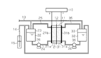
- the redox flow battery includes a charge / discharge cell 11.
- the inside of the charge / discharge cell 11 is partitioned into a positive electrode side cell 21 and a negative electrode side cell 31 by a diaphragm 12.
- the redox flow battery includes a positive electrode electrolyte tank 23 that stores the positive electrode electrolyte 22 used in the positive electrode side cell 21, and a negative electrode electrolyte tank 33 that stores the negative electrode electrolyte 32 used in the negative electrode side cell 31.
- the redox flow battery is provided with a temperature adjusting device for adjusting the temperature around the charge / discharge cell 11 as necessary.
- a positive electrode 21a and a positive electrode current collector plate 21b are arranged in contact with each other.
- a negative electrode 31 a and a negative electrode current collector 31 b are arranged in contact with each other.
- the positive electrode 21a and the negative electrode 31a are made of, for example, carbon felt.
- the positive electrode side current collector plate 21b and the negative electrode side current collector plate 31b are made of, for example, a glassy carbon plate.
- Each of the current collector plates 21 b and 31 b is electrically connected to the charging / discharging device 10.
- a positive electrode electrolyte tank 23 is connected to the positive electrode side cell 21 via a supply pipe 24 and a recovery pipe 25.
- the supply pipe 24 is equipped with a pump 26.
- the positive electrolyte solution 22 in the positive electrode electrolyte tank 23 is supplied to the positive electrode side cell 21 through the supply pipe 24.
- the positive electrode electrolyte 22 in the positive electrode side cell 21 is recovered in the positive electrode electrolyte tank 23 through the recovery tube 25.
- the positive electrode electrolyte 22 circulates between the positive electrode electrolyte tank 23 and the positive electrode side cell 21.
- a negative electrode electrolyte tank 33 is connected to the negative electrode side cell 31 via a supply pipe 34 and a recovery pipe 35.
- the supply pipe 34 is equipped with a pump 36.
- the negative electrode electrolyte 32 in the negative electrode electrolyte tank 33 is supplied to the negative electrode side cell 31 through the supply pipe 34.
- the negative electrode electrolyte 32 in the negative electrode side cell 31 is recovered in the negative electrode electrolyte tank 33 through the recovery pipe 35.
- the negative electrode electrolyte 32 circulates between the negative electrode electrolyte tank 33 and the negative electrode side cell 31.
- the charge / discharge cell 11, the positive electrode electrolyte tank 23 and the negative electrode electrolyte tank 33 are connected to an inert gas supply pipe 13 for supplying an inert gas thereto.
- An inert gas is supplied to the inert gas supply pipe 13 from an inert gas generator (not shown).
- an inert gas generator not shown.
- nitrogen gas is used as the inert gas.
- the inert gas supplied to the positive electrode electrolyte tank 23 and the negative electrode electrolyte tank 33 is exhausted through the exhaust pipe 14.
- a water seal portion 15 that seals the front end opening of the exhaust pipe 14 is provided at the distal end of the exhaust pipe 14 on the discharge side.
- the water seal 15 prevents the air from flowing back into the exhaust pipe 14 and keeps the pressure in the positive electrolyte tank 23 and the negative electrolyte tank 33 constant.
- an oxidation reaction is performed in the positive electrode electrolyte solution 22 in contact with the positive electrode 21a, and a reduction reaction is performed in the negative electrode electrolyte solution 32 in contact with the negative electrode 31a. That is, the positive electrode 21a emits electrons and the negative electrode 31a receives electrons.
- the positive collector plate 21b supplies the electrons discharged from the positive electrode 21a to the charging / discharging device 10.
- the negative electrode current collector 31b supplies the electrons received from the charge / discharge device 10 to the negative electrode 31a.
- a reduction reaction is performed in the positive electrode electrolyte 22 in contact with the positive electrode 21a, and an oxidation reaction is performed in the negative electrode electrolyte 32 in contact with the negative electrode 31a. That is, the positive electrode 21a receives electrons and the negative electrode 31a emits electrons. At this time, the positive collector plate 21b supplies the electrons received from the charge / discharge device 10 to the positive electrode 21a.
- the redox flow battery includes a negative electrode electrolyte 32 containing a redox material of zinc and a nitrogen-containing heterocyclic compound.
- zinc functions as an active material. For example, reduction from Zn (II) to Zn (0) occurs during charging, and oxidation from Zn (0) to Zn (II) occurs during discharging. Is presumed to occur.
- the concentration of the zinc redox substance (zinc ions) in the negative electrode electrolyte solution 32 is preferably 0.4 mol / L or more from the viewpoint of increasing the energy density.
- the concentration of the zinc redox substance (zinc ions) in the negative electrode electrolyte solution 32 is preferably 2.0 mol / L or less.
- Examples of the nitrogen-containing heterocyclic compound contained in the negative electrode electrolyte solution 32 include aromatic heterocyclic compounds and aliphatic heterocyclic compounds.
- the nitrogen-containing heterocyclic compound may be a nitrogen-containing heterocyclic compound having a monocyclic structure or a nitrogen-containing heterocyclic compound having a polycyclic structure.
- Examples of the aromatic heterocyclic compound include a five-membered aromatic heterocyclic compound and a six-membered aromatic heterocyclic compound.
- Examples of the five-membered aromatic heterocyclic compound include imidazole, imidazoline, pyrazole, and triazole.
- Examples of the six-membered aromatic heterocyclic compound include pyridine and pyridazine.
- Examples of the aliphatic heterocyclic compound include pyrrolidine (5-membered ring), piperidine (6-membered ring), and piperazine (6-membered ring).
- the nitrogen-containing heterocyclic compound may be an alkyl-substituted product having an alkyl group as a substituent or an amino-substituted product having an amino group in addition to the above-described unsubstituted compound.
- the alkyl group preferably has 1 or more and 4 or less carbon atoms.
- the negative electrode electrolyte solution 32 may contain only one type or a plurality of types of nitrogen-containing heterocyclic compounds.
- the nitrogen-containing heterocyclic compound preferably includes a five-membered aromatic heterocyclic compound, more preferably includes a five-membered aromatic heterocyclic compound having two or more nitrogen atoms in the heterocyclic ring, and triazole. It is further preferable to include it.
- the triazole include at least one selected from an unsubstituted triazole (1,2,4-triazole or 1,2,3-triazole) and an alkyl-substituted product or an amino-substituted product thereof.
- the triazoles at least one selected from 1,2,4-triazole and its alkyl-substituted product or amino-substituted product is preferable, and 1,2,4-triazole is more preferable.
- the molar ratio of the nitrogen-containing heterocyclic compound to the redox substance of zinc in the negative electrode electrolyte solution 32 is preferably in the range of 1 to 5, more preferably in the range of 1 to 3. .
- the molar ratio is 1 or more, it is easy to increase the concentration of the zinc redox substance.
- the molar ratio is 5 or less, precipitates are less likely to be generated in the negative electrode electrolyte solution 32. Therefore, the zinc redox material can be used more effectively.
- the pH of the negative electrode electrolyte solution 32 is preferably in the range of 3 or more and 6 or less. When the pH of the negative electrode electrolyte 32 is 3 or more, it is easy to increase the concentration of the zinc redox material. When the pH of the negative electrode electrolyte 32 is 6 or less, it is possible to reduce the chemical resistance required for the material constituting the battery.
- the pH is a value measured at 20 ° C., for example.
- the negative electrode electrolyte solution 32 may contain, for example, an inorganic acid salt, an organic acid salt, or a chelating agent as necessary.
- the active material used for the positive electrode electrolyte 22 is not particularly limited, and examples thereof include iron redox materials, chromium redox materials, manganese redox materials, copper redox materials, vanadium redox materials, and bromine. The redox-type substance of this is mentioned.
- the concentration of the metal redox substance (metal ion) in the positive electrode electrolyte 22 is preferably 0.1 mol / L or more, more preferably 0.2 mol / L or more, from the viewpoint of increasing the energy density. More preferably 0.4 mol / L or more.
- the concentration of the metal redox substance (metal ion) in the positive electrode electrolyte 22 is preferably 2.5 mol / L or less, more preferably 1. from the viewpoint of suppressing the precipitation of the metal redox substance. 5 mol / L or less.
- the active material used for the positive electrode electrolyte 22 for example, a redox material of manganese is preferable.
- Preparation of the positive electrode electrolyte solution 22 containing manganese is preferably performed, for example, by dissolving manganese sulfate in water in order to avoid mixing of chlorine ions.
- Manganese contained in the positive electrode electrolyte 22 is presumed to be oxidized from Mn (III) to Mn (IV) during charging and reduced from Mn (IV) to Mn (III) during discharging.
- the positive electrode electrolyte 22 preferably further contains a chelating agent.
- chelating agents include amines, polyethyleneimines, and aminocarboxylic acid chelating agents.
- the amine is represented by the general formula (1).
- n represents an integer of 0 to 4
- R 1 , R 2 , R 3 and R 4 independently represent a hydrogen atom, a methyl group or an ethyl group.
- the amine represented by the general formula (1) is a kind of chelating agent, and can form a complex with a metal redox substance. Therefore, when a metal redox material is used for the positive electrode electrolyte 22, it functions to stabilize the redox reaction, for example.
- EDA ethylenediamine
- DETA diethylenetriamine
- TETA triethylenetetramine
- TMEDA tetramethylethylenediamine
- N, N-dimethylethylenediamine 0
- N-ethylethylenediamine 0
- the positive electrode electrolyte solution 22 may contain only one type of amine represented by the general formula (1), or may contain a plurality of types.
- the positive electrode electrolyte 22 preferably contains at least one amine selected from diethylenetriamine, triethylenetetramine, and N, N′-dimethylethylenediamine.
- the molar ratio of the chelating agent to the metal redox substance in the positive electrode electrolyte solution 22 is preferably in the range of 0.5 or more and 10 or less, and more preferably in the range of 1 or more and 5 or less. .
- the positive electrode electrolyte solution 22 can contain, for example, an inorganic acid salt or an organic acid salt, if necessary.
- the pH of the positive electrode electrolyte 22 is preferably in the range of 3 or more and 11 or less.
- the negative electrode electrolyte 32 and the positive electrode electrolyte 22 can be prepared by a known method.
- the negative electrode electrolyte solution 32 contains a zinc redox material, for example, it is preferable to dissolve zinc sulfate (ZnSO 4 ) in water because it is easily available.
- the water used for the negative electrode electrolyte 32 and the positive electrode electrolyte 22 preferably has a purity equal to or higher than that of distilled water.
- the redox flow battery can be charged / discharged with the negative electrode electrolyte 32 and the positive electrode electrolyte 22 in an inert gas atmosphere as necessary.
- the negative electrode electrolyte solution 32 containing the zinc redox substance and the nitrogen-containing heterocyclic compound the zinc redox substance and the nitrogen-containing heterocyclic compound form a complex, thereby forming a zinc redox substance. It is assumed that the redox reaction is stabilized. Thereby, practical performance as a redox flow battery is easily obtained.
- the nitrogen-containing heterocyclic compound is presumed to have a higher effect of stably dissolving the redox substance of zinc than, for example, the amine represented by the general formula (1). Even if the concentration of the redox material is increased, the charge / discharge efficiency is hardly lowered.
- the performance of a redox flow battery can be evaluated by, for example, charge / discharge cycle characteristics (reversibility), coulomb efficiency, voltage efficiency, energy efficiency, electrolyte utilization, electromotive force, and electrolyte potential.
- charge / discharge cycle characteristics reversibility
- coulomb efficiency voltage efficiency
- energy efficiency energy efficiency
- electrolyte utilization electromotive force
- electrolyte potential electrolyte potential
- the charge / discharge cycle characteristics (reversibility) are calculated by substituting the coulomb amount (A) for the fifth cycle discharge and the coulomb amount (B) for the 40th cycle discharge into the following equation (1).
- Charging / discharging cycle characteristics [%] B / A ⁇ 100 (1)
- the charge / discharge cycle characteristics are preferably 80% or more.
- the coulomb efficiency is calculated by substituting the coulomb amount (C) for charging and the coulomb amount (D) for discharging in a predetermined cycle into the following equation (2).
- Coulomb efficiency [%] D / C ⁇ 100 (2)
- the coulomb efficiency is preferably 80% or more in a value calculated from the coulomb amount at the 25th cycle, for example.
- the voltage efficiency is calculated by substituting the average terminal voltage (E) for charging and the average terminal voltage (F) for discharging in a predetermined cycle into the following formula (3).
- Voltage efficiency [%] F / E ⁇ 100 (3)
- the voltage efficiency is preferably 60% or more in a value calculated from the terminal voltage at the 25th cycle, for example.
- the energy efficiency is calculated by substituting the electric energy (G) for charging and the electric energy (H) for discharging in a predetermined cycle into the following formula (4).
- Energy efficiency [%] H / G ⁇ 100 (4)
- the energy efficiency is preferably 60% or more in a value calculated from the electric energy at the 25th cycle.
- the utilization rate of the electrolytic solution is obtained by multiplying the number of moles of the active material of the electrolytic solution supplied to the positive electrode 21a side or the negative electrode 31a side by the Faraday constant (96500 coulomb / mol) to obtain the coulomb amount (I) and a predetermined cycle. It is calculated by obtaining the coulomb amount (J) of the eye discharge and substituting the coulomb amount (I) and the coulomb amount (J) into the following equation (5). In addition, when the number of moles of the active material of the electrolytic solution supplied to the positive electrode 21a side is different from the number of moles of the active material of the electrolytic solution supplied to the negative electrode 31a side, a smaller number of moles is adopted.
- Utilization rate of electrolytic solution [%] J / I ⁇ 100 (5)
- the utilization factor of the electrolytic solution is preferably 35% or more in a value calculated from the amount of coulomb in the second cycle.
- the electromotive force is a terminal voltage when switching from charging to discharging (when the current is 0 mA) in a predetermined cycle.
- the electromotive force is preferably 1.0 V or more at the terminal voltage in the second cycle.
- the redox flow battery of this embodiment includes a negative electrode electrolyte solution 32 containing a zinc redox material and a nitrogen-containing heterocyclic compound.
- a negative electrode electrolyte solution 32 containing a zinc redox material and a nitrogen-containing heterocyclic compound.
- the nitrogen-containing heterocyclic compound preferably includes a five-membered aromatic heterocyclic compound.
- a redox flow battery can be configured at a relatively low cost, and thus a highly practical redox flow battery can be provided.
- the molar ratio of the nitrogen-containing heterocyclic compound to the zinc redox substance in the negative electrode electrolyte is preferably in the range of 1 or more and 5 or less. In this case, it is presumed that the redox reaction of the redox substance of zinc is further stabilized, and generation of precipitates can be suppressed. Accordingly, it becomes possible to more effectively utilize the zinc redox material.
- the content of the zinc redox substance in the negative electrode electrolyte is preferably 0.4 mol / L or more. In this case, a redox flow battery having a higher energy density can be provided.
- the pH of the negative electrode electrolyte is preferably in the range of 3 or more and 6 or less. In this case, the corrosion resistance is easily ensured, and the solubility of the zinc redox substance is easily ensured.
- the embodiment may be modified as follows. -The shape, arrangement
- Example 1 ⁇ Redox flow battery> As a positive electrode and a negative electrode, the electrode area was set to 10 cm 2 using carbon felt (trade name: GFA5, manufactured by SGL). As the positive electrode side current collector plate, a pure titanium plate having a thickness of 0.6 mm was used. As the negative electrode side current collector plate, a glassy carbon plate (trade name: SG carbon, thickness 0.6 mm, manufactured by Showa Denko KK) was used. As the diaphragm, a cation exchange membrane (CMS, manufactured by Astom Corp.) was used.
- CMS cation exchange membrane
- a glass container with a capacity of 30 mL was used as the positive electrode electrolyte tank and the negative electrode electrolyte tank. Silicone tubes were used as the supply pipe, recovery pipe, inert gas supply pipe, and exhaust pipe.
- a micro tube pump MP-1000, manufactured by Tokyo Rika Kikai Co., Ltd.
- PFX200 manufactured by Kikusui Electronics Co., Ltd.
- a positive electrode electrolyte was prepared by electrolytic oxidation of an aqueous Mn (II) -TETA complex solution.
- 20 mL of an aqueous Mn (II) -TETA complex solution was placed in the positive electrode electrolyte tank, and 10 mL of an aqueous Zn (II) -triazole complex solution was placed in the negative electrode electrolyte tank.
- the redox flow battery was charged with a constant current of 100 mA for 60 minutes (total 360 coulombs).
- the Mn (II) -TETA complex contained in the aqueous solution in the positive electrode electrolyte tank was electrolytically oxidized to prepare an aqueous solution having a Mn (III) -TETA complex concentration of 0.2 mol / L. was used as the positive electrode electrolyte.
- Mn (III) Mn (III)
- a charge / discharge test was conducted using an aqueous Mn (III) -TETA complex solution obtained by electrolytic oxidation as the positive electrode electrolyte and using an aqueous Zn (II) -triazole complex as the negative electrode electrolyte.
- the charge / discharge test was started from charging, and was first charged with a constant current of 100 mA for 30 minutes (total 180 coulombs). Next, the battery was discharged at a constant current of 100 mA with a final discharge voltage of 0V.
- FIG. 2 shows changes in battery voltage during charge / discharge from the 25th cycle to the 27th cycle.
- charge / discharge cycle characteristics (reversibility), coulomb efficiency, voltage efficiency, energy efficiency, electrolyte utilization, and electromotive force were determined.
- the charge / discharge cycle characteristics were determined from the coulombic amount (A) of the fifth cycle discharge and the coulomb amount (B) of the 40th cycle discharge.
- the coulomb efficiency was determined from the coulomb amount at the 25th cycle.
- the voltage efficiency was determined from the average terminal voltage at the 25th cycle.
- the energy efficiency was obtained from the electric energy at the 25th cycle.
- the utilization factor of the electrolytic solution was obtained from the amount of coulomb at the second cycle.
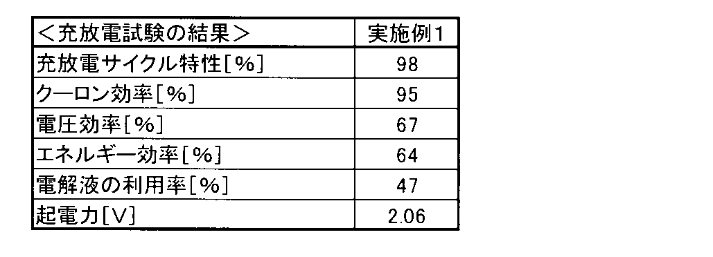
- the electromotive force was the terminal voltage at the second cycle. The results are shown in Table 1.
- aqueous Zn (II) -TETA complex solution 0.08 mol (11.9 g) of triethylenetetramine (TETA) was first dissolved in 50 mL of distilled water. In this aqueous solution, 0.04 mol (11.5 g) of ZnSO 4 .7H 2 O was dissolved. The pH of the obtained aqueous solution was 10.69. Next, 2.5 mol / L of dilute sulfuric acid was added dropwise to the aqueous solution to adjust the pH of the aqueous solution to 6.0, and 0.05 mol (7.1 g) of Na 2 SO 4 was dissolved therein. Next, distilled water was added to the aqueous solution so that the total amount became 100 mL. As a result, a 0.4 mol / L Zn (II) -TETA complex aqueous solution was obtained. The pH of the obtained Zn (II) -triazole complex aqueous solution was 6.25.
- the battery was charged with a constant current of 100 mA for 30 minutes, and then discharged with a constant current of 100 mA and a final discharge voltage of 0.7V. Such charging / discharging was performed 50 cycles.
- the charge / discharge test of Comparative Example 1 the charge / discharge cycle characteristics were 105%, the coulomb efficiency was 65%, the voltage efficiency was 58%, and the energy efficiency was 38%.
- Example 1 has a higher Coulomb efficiency than Comparative Example 1.
Landscapes
- Life Sciences & Earth Sciences (AREA)
- Engineering & Computer Science (AREA)
- Manufacturing & Machinery (AREA)
- Sustainable Development (AREA)
- Sustainable Energy (AREA)
- Chemical & Material Sciences (AREA)
- Chemical Kinetics & Catalysis (AREA)
- Electrochemistry (AREA)
- General Chemical & Material Sciences (AREA)
- Fuel Cell (AREA)
Abstract
レドックスフロー電池は、亜鉛のレドックス系物質と、含窒素複素環式化合物とを含有する負極電解液を備える。
Description
本発明は、レドックスフロー電池に関する。
一般的にレドックスフロー電池では強酸性の電解液が用いられる。強酸性の電解液の例としては、バナジウムのレドックス系物質を含有する電解液が実用化されている。強酸性の電解液中における金属レドックスイオンは、比較的高濃度であっても安定して溶解されるため、電池のエネルギー密度を高くすることができる。ところが、レドックスフロー電池を構成する材料には、強酸性の電解液に耐え得る耐薬品性が求められる。
これに対して、例えば、pH3以上の電解液を用いる場合では、強酸性の電解液を用いる場合よりも、レドックスフロー電池を構成する材料に求められる耐薬品性は緩和される。ところが、pH3以上の電解液中では、活物質となる金属レドックスイオンを安定して溶解させることが困難となる。この点、特許文献1には、金属レドックスイオンの錯体を用いることで、電解液中における金属レドックスイオンの溶解性を高める技術が開示されている。
上述したように、中性付近のpHを有する電解液(例えば、pH3以上の電解液)を用いたレドックスフロー電池では、電池を構成する材料に求められる耐薬品性が緩和されるため、高価な材料の使用を回避することが可能となる。したがって、設備の低コスト化が実現可能となる点で有利である。このような電解液中の金属レドックスイオンの含有量を高めることは、エネルギー密度を高めた実用的なレドックスフロー電池を提供できる点で有利である。ところが、上記のようにエネルギー密度を高めた場合、充放電効率が低下し易くなる。
本発明は、こうした実情に鑑みてなされたものであり、その目的は、中性付近のpHを有する電解液中における金属レドックスイオンの含有量を高めたとしても、充放電効率が低下し難いレドックスフロー電池を提供することにある。
上記の目的を達成するために、本発明の一態様では、亜鉛のレドックス系物質と、含窒素複素環式化合物とを含有する負極電解液を備えるレドックスフロー電池を提供する。
本出願で記載する「レドックス系物質」とは、金属の酸化還元反応で生成する金属イオン、金属錯イオン又は金属のことを言う。
本出願で記載する「レドックス系物質」とは、金属の酸化還元反応で生成する金属イオン、金属錯イオン又は金属のことを言う。
前記レドックスフロー電池において、前記含窒素複素環式化合物は、五員芳香族複素環式化合物を含むことが好ましい。
前記レドックスフロー電池において、前記負極電解液中の亜鉛のレドックス系物質に対する前記含窒素複素環式化合物のモル比は、1以上、5以下の範囲内であることが好ましい。
前記レドックスフロー電池において、前記負極電解液中の亜鉛のレドックス系物質に対する前記含窒素複素環式化合物のモル比は、1以上、5以下の範囲内であることが好ましい。
前記レドックスフロー電池において、前記負極電解液中の前記亜鉛のレドックス系物質の含有量は、0.4モル/L以上であることが好ましい。
前記レドックスフロー電池において、前記負極電解液のpHは、3以上、6以下の範囲内であることが好ましい。
前記レドックスフロー電池において、前記負極電解液のpHは、3以上、6以下の範囲内であることが好ましい。
以下、本発明の実施形態に係るレドックスフロー電池について説明する。
<レドックスフロー電池の構造>
図1に示すように、レドックスフロー電池は、充放電セル11を備える。充放電セル11の内部は、隔膜12によって正極側セル21と負極側セル31とに仕切られている。レドックスフロー電池は、正極側セル21に用いられる正極電解液22を貯蔵する正極電解液タンク23と、負極側セル31に用いられる負極電解液32を貯蔵する負極電解液タンク33とを備える。レドックスフロー電池には、充放電セル11の周辺の温度を調節する温度調節装置が必要に応じて設けられる。
<レドックスフロー電池の構造>
図1に示すように、レドックスフロー電池は、充放電セル11を備える。充放電セル11の内部は、隔膜12によって正極側セル21と負極側セル31とに仕切られている。レドックスフロー電池は、正極側セル21に用いられる正極電解液22を貯蔵する正極電解液タンク23と、負極側セル31に用いられる負極電解液32を貯蔵する負極電解液タンク33とを備える。レドックスフロー電池には、充放電セル11の周辺の温度を調節する温度調節装置が必要に応じて設けられる。
正極側セル21には、正極21aと正極側集電板21bとが互いに接触した状態で配置されている。負極側セル31には、負極31aと負極側集電板31bとが互いに接触した状態で配置されている。正極21a及び負極31aは、例えばカーボン製のフェルトから構成される。正極側集電板21b及び負極側集電板31bは、例えばガラス状カーボン板から構成される。各集電板21b,31bは、充放電装置10に電気的に接続されている。
正極側セル21には、供給管24及び回収管25を介して正極電解液タンク23が接続されている。供給管24には、ポンプ26が装備されている。このポンプ26の作動により、正極電解液タンク23内の正極電解液22は、供給管24を通じて正極側セル21に供給される。このとき、正極側セル21内の正極電解液22は、回収管25を通じて正極電解液タンク23に回収される。このように正極電解液22は、正極電解液タンク23と正極側セル21との間を循環する。
負極側セル31には、供給管34及び回収管35を介して負極電解液タンク33が接続されている。供給管34には、ポンプ36が装備されている。このポンプ36の作動により、負極電解液タンク33内の負極電解液32は、供給管34を通じて負極側セル31に供給される。このとき、負極側セル31内の負極電解液32は、回収管35を通じて負極電解液タンク33に回収される。このように負極電解液32は、負極電解液タンク33と負極側セル31との間を循環する。
充放電セル11、正極電解液タンク23及び負極電解液タンク33には、それらに不活性ガスを供給するための不活性ガス供給管13が接続されている。不活性ガス供給管13には、図示を省略した不活性ガス発生装置から不活性ガスが供給される。この不活性ガス供給管13を通じて正極電解液タンク23及び負極電解液タンク33に不活性ガスが供給されることで、正極電解液22及び負極電解液32と大気中の酸素との接触が抑制される。不活性ガスとしては、例えば窒素ガスが用いられる。正極電解液タンク23及び負極電解液タンク33に供給された不活性ガスは、排気管14を通じて排気される。排気管14の排出側の先端には、排気管14の先端開口を水封する水封部15が設けられている。水封部15は、排気管14内に大気が逆流することを防止するとともに、正極電解液タンク23内及び負極電解液タンク33内の圧力を一定に保つ。
充電時には、正極21aに接触する正極電解液22中で酸化反応が行われるとともに、負極31aに接触する負極電解液32中で還元反応が行われる。すなわち、正極21aは電子を放出するとともに、負極31aは電子を受け取る。このとき、正極側集電板21bは、正極21aから放出された電子を充放電装置10に供給する。負極側集電板31bは、充放電装置10から受け取った電子を負極31aに供給する。
放電時には、正極21aに接触する正極電解液22中で還元反応が行われるとともに、負極31aに接触する負極電解液32中で酸化反応が行われる。すなわち、正極21aは電子を受け取るとともに、負極31aは電子を放出する。このとき、正極側集電板21bは、充放電装置10から受け取った電子を正極21aに供給する。
<電解液>
レドックスフロー電池は、亜鉛のレドックス系物質と含窒素複素環式化合物とを含有する負極電解液32を備える。
レドックスフロー電池は、亜鉛のレドックス系物質と含窒素複素環式化合物とを含有する負極電解液32を備える。
負極電解液32中では、亜鉛が活物質として機能し、例えば、充電時には、Zn(II)からZn(0)への還元が起こり、放電時には、Zn(0)からZn(II)への酸化が起こると推測される。
負極電解液32中における亜鉛のレドックス系物質(亜鉛イオン)の濃度は、エネルギー密度を高めるという観点から、好ましくは0.4モル/L以上である。負極電解液32中における亜鉛のレドックス系物質(亜鉛イオン)の濃度は、好ましくは2.0モル/L以下である。
負極電解液32に含有される含窒素複素環式化合物としては、芳香族複素環式化合物及び脂肪族複素環式化合物が挙げられる。含窒素複素環式化合物は、単環構造を有する含窒素複素環式化合物であってもよいし、多環構造を有する含窒素複素環式化合物であってもよい。
芳香族複素環式化合物としては、例えば、五員芳香族複素環式化合物、及び六員芳香族複素環式化合物が挙げられる。五員芳香族複素環式化合物としては、例えば、イミダゾール、イミダゾリン、ピラゾール、及びトリアゾールが挙げられる。六員芳香族複素環式化合物としては、例えば、ピリジン、及びピリダジンが挙げられる。
脂肪族複素環式化合物としては、例えば、ピロリジン(五員環)、ピペリジン(六員環)、及びピペラジン(六員環)が挙げられる。
含窒素複素環式化合物は、上述したような非置換の化合物以外に、置換基としてアルキル基を有するアルキル置換体やアミノ基を有するアミノ置換体であってもよい。アルキル基の炭素数は、1以上、4以下であることが好ましい。
含窒素複素環式化合物は、上述したような非置換の化合物以外に、置換基としてアルキル基を有するアルキル置換体やアミノ基を有するアミノ置換体であってもよい。アルキル基の炭素数は、1以上、4以下であることが好ましい。
負極電解液32は、含窒素複素環式化合物のうち一種類のみを含有してもよいし、複数種を含有してもよい。含窒素複素環式化合物は、五員芳香族複素環式化合物を含むことが好ましく、複素環に2つ以上の窒素原子を有する五員芳香族複素環式化合物を含むことがより好ましく、トリアゾールを含むことがさらに好ましい。トリアゾールとしては、例えば、非置換のトリアゾール(1,2,4-トリアゾール又は1,2,3-トリアゾール)と、そのアルキル置換体又はアミノ置換体とから選ばれる少なくとも一種が挙げられる。トリアゾールの中でも、1,2,4-トリアゾールとそのアルキル置換体又はアミノ置換体とから選ばれる少なくとも一種であることが好ましく、より好ましくは1,2,4-トリアゾールである。
負極電解液32中の亜鉛のレドックス系物質に対する含窒素複素環式化合物のモル比は、1以上、5以下の範囲内であることが好ましく、より好ましくは1以上、3以下の範囲内である。前記モル比が1以上の場合、亜鉛のレドックス系物質の濃度を高めることが容易となる。前記モル比が5以下の場合、負極電解液32中に析出物が生じ難くなる傾向となるため、亜鉛レドックス系物質をより有効に利用することができる。
負極電解液32のpHは、好ましくは3以上、6以下の範囲内である。負極電解液32のpHが3以上の場合、亜鉛のレドックス系物質の濃度を高めることが容易となる。負極電解液32のpHが6以下の場合、電池を構成する材料に必要な耐薬品性を低めることが可能となる。なお、pHは、例えば20℃で測定される値である。
負極電解液32には、必要に応じて、例えば、無機酸の塩又は有機酸の塩、キレート剤を含有させることもできる。
正極電解液22に用いる活物質としては、特に限定されず、例えば、鉄のレドックス系物質、クロムのレドックス系物質、マンガンのレドックス系物質、銅のレドックス系物質、バナジウムのレドックス系物質、及び臭素のレドックス系物質が挙げられる。
正極電解液22に用いる活物質としては、特に限定されず、例えば、鉄のレドックス系物質、クロムのレドックス系物質、マンガンのレドックス系物質、銅のレドックス系物質、バナジウムのレドックス系物質、及び臭素のレドックス系物質が挙げられる。
正極電解液22中における金属のレドックス系物質(金属イオン)の濃度は、エネルギー密度を高めるという観点から、好ましくは0.1モル/L以上であり、より好ましくは0.2モル/L以上であり、さらに好ましくは0.4モル/L以上である。
正極電解液22中における金属のレドックス系物質(金属イオン)の濃度は、金属のレドックス系物質の析出を抑制するという観点から、好ましくは2.5モル/L以下であり、より好ましくは1.5モル/L以下である。
正極電解液22に用いる活物質としては、例えばマンガンのレドックス系物質が好適である。マンガンを含有した正極電解液22の調製は、塩素イオンの混入を避けるために、例えば硫酸マンガンを水に溶解させることによって行われることが好ましい。正極電解液22中に含まれるマンガンは、充電時には、Mn(III)からMn(IV)に酸化され、放電時には、Mn(IV)からMn(III)に還元されると推測される。
正極電解液22は、さらにキレート剤を含有することが好ましい。キレート剤の例としては、例えば、アミン、ポリエチレンイミン、及びアミノカルボン酸系キレート剤が挙げられる。
アミンは、一般式(1)で表される。

一般式(1)で表されるアミンは、キレート剤の一種であり、金属のレドックス系物質と錯体を生成することができる。従って、正極電解液22に金属のレドックス系物質を用いたときに、例えばレドックス反応を安定化する働きをする。
一般式(1)で表されるアミンの例としては、例えば、エチレンジアミン(EDA,n=0)、ジエチレントリアミン(DETA,n=1)、トリエチレンテトラミン(TETA,n=2)、テトラエチレンペンタミン(TEPA,n=3)、ペンタエチレンヘキサミン(PEHA,n=4)、テトラメチルエチレンジアミン(TMEDA,n=0)、N-メチルエチレンジアミン(n=0)、N,N´-ジメチルエチレンジアミン(DMEDA,n=0)、N,N-ジメチルエチレンジアミン(n=0)、N-エチルエチレンジアミン(n=0)、N,N´-ジエチルエチレンジアミン(n=0)及びN,N-ジエチルエチレンジアミン(n=0)が挙げられる。
正極電解液22は、一般式(1)で表されるアミンのうち一種類のみを含有してもよいし、複数種を含有してもよい。
正極電解液22は、ジエチレントリアミン、トリエチレンテトラミン、及びN,N´-ジメチルエチレンジアミンから選ばれる少なくとも一種のアミンを含有することが好ましい。
正極電解液22は、ジエチレントリアミン、トリエチレンテトラミン、及びN,N´-ジメチルエチレンジアミンから選ばれる少なくとも一種のアミンを含有することが好ましい。
正極電解液22中の金属のレドックス系物質に対するキレート剤のモル比は、例えば0.5以上、10以下の範囲内であることが好ましく、1以上、5以下の範囲内であることがより好ましい。
正極電解液22には、必要に応じて、例えば、無機酸の塩又は有機酸の塩を含有させることもできる。
正極電解液22のpHは、好ましくは3以上、11以下の範囲内である。
正極電解液22のpHは、好ましくは3以上、11以下の範囲内である。
負極電解液32及び正極電解液22は、公知の方法で調製することができる。負極電解液32に亜鉛のレドックス系物質を含有させる際には、例えば入手が容易であることから、硫酸亜鉛(ZnSO4)を水に溶解させることが好ましい。
負極電解液32及び正極電解液22に用いる水は、蒸留水と同等又はそれ以上の純度を有していることが好ましい。レドックスフロー電池の充放電は、必要に応じて負極電解液32及び正極電解液22を不活性ガスの雰囲気下にして行うことができる。
<レドックスフロー電池の作用>
亜鉛のレドックス系物質と含窒素複素環式化合物とを含有する負極電解液32中では、亜鉛のレドックス系物質と含窒素複素環式化合物とが錯体を形成することで、亜鉛のレドックス系物質のレドックス反応が安定化されると推測される。これにより、レドックスフロー電池としての実用的な性能が得られ易くなる。しかも、含窒素複素環式化合物は、例えば、一般式(1)で表されるアミンよりも、亜鉛のレドックス系物質を安定して溶解させる効果が高いと推測され、負極電解液32中における亜鉛のレドックス系物質の濃度を高めたとしても、充放電効率が低下し難くなる。
亜鉛のレドックス系物質と含窒素複素環式化合物とを含有する負極電解液32中では、亜鉛のレドックス系物質と含窒素複素環式化合物とが錯体を形成することで、亜鉛のレドックス系物質のレドックス反応が安定化されると推測される。これにより、レドックスフロー電池としての実用的な性能が得られ易くなる。しかも、含窒素複素環式化合物は、例えば、一般式(1)で表されるアミンよりも、亜鉛のレドックス系物質を安定して溶解させる効果が高いと推測され、負極電解液32中における亜鉛のレドックス系物質の濃度を高めたとしても、充放電効率が低下し難くなる。
レドックスフロー電池の性能は、例えば、充放電サイクル特性(可逆性)、クーロン効率、電圧効率、エネルギー効率、電解液の利用率、起電力、及び電解液の電位により評価することができる。以下では、レドックスフロー電池の充放電1回を1サイクルという。
充放電サイクル特性(可逆性)は、5サイクル目の放電のクーロン量(A)と40サイクル目の放電のクーロン量(B)とを下記式(1)に代入することで算出される。
充放電サイクル特性[%]=B/A×100 ・・・(1)
充放電サイクル特性は、好ましくは80%以上である。
充放電サイクル特性[%]=B/A×100 ・・・(1)
充放電サイクル特性は、好ましくは80%以上である。
クーロン効率は、所定のサイクル目の充電のクーロン量(C)と放電のクーロン量(D)とを下記式(2)に代入することで算出される。
クーロン効率[%]=D/C×100 ・・・(2)
クーロン効率は、例えば、25サイクル目のクーロン量から算出される値において、好ましくは80%以上である。
クーロン効率[%]=D/C×100 ・・・(2)
クーロン効率は、例えば、25サイクル目のクーロン量から算出される値において、好ましくは80%以上である。
電圧効率は、所定のサイクル目の充電の平均端子電圧(E)と放電の平均端子電圧(F)とを下記式(3)に代入することで算出される。
電圧効率[%]=F/E×100 ・・・(3)
電圧効率は、例えば、25サイクル目の端子電圧から算出される値において、好ましくは60%以上である。
電圧効率[%]=F/E×100 ・・・(3)
電圧効率は、例えば、25サイクル目の端子電圧から算出される値において、好ましくは60%以上である。
エネルギー効率は、所定のサイクル目の充電の電力量(G)と放電の電力量(H)とを下記式(4)に代入することで算出される。
エネルギー効率[%]=H/G×100 ・・・(4)
エネルギー効率は、25サイクル目の電力量から算出される値において、好ましくは60%以上である。
エネルギー効率[%]=H/G×100 ・・・(4)
エネルギー効率は、25サイクル目の電力量から算出される値において、好ましくは60%以上である。
電解液の利用率は、正極21a側又は負極31a側に供給される電解液の活物質のモル数にファラデー定数(96500クーロン/モル)を乗じてクーロン量(I)を求めるとともに、所定のサイクル目の放電のクーロン量(J)を求め、クーロン量(I)とクーロン量(J)とを下記式(5)に代入することで算出される。なお、正極21a側に供給される電解液の活物質のモル数と負極31a側に供給される電解液の活物質のモル数とが異なる場合は、より小さいモル数を採用する。
電解液の利用率[%]=J/I×100 ・・・(5)
電解液の利用率は、2サイクル目のクーロン量から算出される値において、好ましくは35%以上である。
電解液の利用率は、2サイクル目のクーロン量から算出される値において、好ましくは35%以上である。
起電力は、所定のサイクル目において充電から放電に切り替えるとき(電流が0mAのとき)の端子電圧とされる。
起電力は、2サイクル目の端子電圧において、好ましくは1.0V以上である。
起電力は、2サイクル目の端子電圧において、好ましくは1.0V以上である。
以上説明した本実施形態によれば、以下の効果を奏する。
(1)本実施形態のレドックスフロー電池では、亜鉛のレドックス系物質と含窒素複素環式化合物とを含有する負極電解液32を備える。この場合、亜鉛のレドックス系物質のレドックス反応が安定化されると推測される。これにより、中性付近のpHを有する負極電解液32(例えば、pH3以上の負極電解液32)中における金属レドックスイオンの含有量を高めたとしても、充放電効率が低下し難くなる。したがって、上記pHを有する負極電解液32を用いることで電池を構成する材料に求められる耐薬品性を緩和した際に、良好な電池特性を発揮させることが可能となる。
(1)本実施形態のレドックスフロー電池では、亜鉛のレドックス系物質と含窒素複素環式化合物とを含有する負極電解液32を備える。この場合、亜鉛のレドックス系物質のレドックス反応が安定化されると推測される。これにより、中性付近のpHを有する負極電解液32(例えば、pH3以上の負極電解液32)中における金属レドックスイオンの含有量を高めたとしても、充放電効率が低下し難くなる。したがって、上記pHを有する負極電解液32を用いることで電池を構成する材料に求められる耐薬品性を緩和した際に、良好な電池特性を発揮させることが可能となる。
(2)含窒素複素環式化合物は、五員芳香族複素環式化合物を含むことが好ましい。この場合、比較的安価にレドックスフロー電池を構成することが可能となるため、実用性の高いレドックスフロー電池を提供することが可能である。
(3)負極電解液中の亜鉛のレドックス系物質に対する含窒素複素環式化合物のモル比は、1以上、5以下の範囲内であることが好ましい。この場合、亜鉛のレドックス系物質のレドックス反応がさらに安定化され易くなると推測されるとともに析出物の発生も抑えることができる。従って、亜鉛のレドックス系物質をより有効に利用することが可能となる。
(4)負極電解液中の亜鉛のレドックス系物質の含有量は、0.4モル/L以上であることが好ましい。この場合、より高いエネルギー密度を有するレドックスフロー電池を提供することができる。
(5)負極電解液のpHは、3以上、6以下の範囲内であることが好ましい。この場合、耐食性が確保され易くなるとともに、亜鉛のレドックス系物質の溶解性が確保され易くなる。
前記実施形態は以下のように変更されてもよい。
・レドックスフロー電池の有する充放電セル11の形状、配置、又は数や正極電解液タンク23及び負極電解液タンク33の容量はレドックスフロー電池に求められる性能等に応じて変更することができる。また、充放電セル11に対する正極電解液22及び負極電解液32の供給量についても、例えば充放電セル11の容量等に応じて設定することができる。
・レドックスフロー電池の有する充放電セル11の形状、配置、又は数や正極電解液タンク23及び負極電解液タンク33の容量はレドックスフロー電池に求められる性能等に応じて変更することができる。また、充放電セル11に対する正極電解液22及び負極電解液32の供給量についても、例えば充放電セル11の容量等に応じて設定することができる。
次に、実施例及び比較例により本発明をさらに詳細に説明する。
(Zn(II)-トリアゾール錯体の溶解性試験)
蒸留水50mLに0.08モル(5.53g)の1,2,4-トリアゾール(分子量69.07、以下単にトリアゾールという)を溶解させた。この水溶液に、0.08モル(23.0g)のZnSO4・7H2Oを溶解させた後、さらに0.08モル(11.4g)の硫酸ナトリウムを溶解させた。次に、全量が100mLとなるように蒸留水を加えた。得られたZn(II)-トリアゾール錯体水溶液のpHは、4.09であった。
(Zn(II)-トリアゾール錯体の溶解性試験)
蒸留水50mLに0.08モル(5.53g)の1,2,4-トリアゾール(分子量69.07、以下単にトリアゾールという)を溶解させた。この水溶液に、0.08モル(23.0g)のZnSO4・7H2Oを溶解させた後、さらに0.08モル(11.4g)の硫酸ナトリウムを溶解させた。次に、全量が100mLとなるように蒸留水を加えた。得られたZn(II)-トリアゾール錯体水溶液のpHは、4.09であった。
Zn(II)-トリアゾール錯体水溶液を室温(約25℃)、空気下の条件で10日間静置する溶解性試験の結果、水溶液中には析出物が確認されなかった。これにより、Zn(II)-トリアゾール錯体の溶解度は0.8モル/L以上であり、レドックスフロー電池の電解液として利用可能であることが分かる。
なお、0.4モル/LのZn(II)-トリアゾール錯体水溶液において、亜鉛のレドックス系物質(Zn(II))に対するトリアゾールのモル比が1の水溶液と、そのモル比が2の水溶液を調製し、室温、空気下の条件で10日間静置する溶解性試験の結果、前記モル比が2の水溶液では、白色の析出物が確認された。この結果から、前記モル比が1に近いほど、Zn(II)-トリアゾール錯体水溶液の溶解性が高まることが分かる。
また、0.4モル/LのZn(II)-トリアゾール錯体水溶液において、pHが4.64の水溶液と、水酸化ナトリウム水溶液を用いてpHを6.71に調整した水溶液とを調製した結果、pHを6.71の水溶液では、白色の析出物が確認された。この結果から、Zn(II)-トリアゾール錯体水溶液のpHは、例えば、6以下であることが好ましいことが分かる。
(実施例1)
<レドックスフロー電池>
正極及び負極としては、カーボンフェルト(商品名:GFA5、SGL社製)を用いて電極面積を10cm2に設定した。正極側集電板としては、厚み0.6mmの純チタン板を用いた。負極側集電板としては、ガラス状カーボン板(商品名:SGカーボン、厚み0.6mm、昭和電工株式会社製)を用いた。隔膜としては、陽イオン交換膜(CMS、アストム社製)を用いた。
<レドックスフロー電池>
正極及び負極としては、カーボンフェルト(商品名:GFA5、SGL社製)を用いて電極面積を10cm2に設定した。正極側集電板としては、厚み0.6mmの純チタン板を用いた。負極側集電板としては、ガラス状カーボン板(商品名:SGカーボン、厚み0.6mm、昭和電工株式会社製)を用いた。隔膜としては、陽イオン交換膜(CMS、アストム社製)を用いた。
正極電解液タンク及び負極電解液タンクとしては、容量30mLのガラス容器を用いた。供給管、回収管、不活性ガス供給管及び排気管としては、シリコーン製のチューブを用いた。ポンプとしては、マイクロチューブポンプ(MP-1000、東京理化器械株式会社製)を用いた。充放電装置としては、充放電バッテリテストシステム(PFX200、菊水電子工業株式会社製)を用いた。
<Zn(II)-トリアゾール錯体水溶液の調製>
上述したZn(II)-トリアゾール錯体の溶解性試験におけるZn(II)-トリアゾール錯体水溶液と同じ方法で0.8モル/LのZn(II)-トリアゾール錯体水溶液を調製した。
上述したZn(II)-トリアゾール錯体の溶解性試験におけるZn(II)-トリアゾール錯体水溶液と同じ方法で0.8モル/LのZn(II)-トリアゾール錯体水溶液を調製した。
<Mn(II)-TETA錯体水溶液の調製>
蒸留水50mLに0.02モル(2.92g)のトリエチレンテトラミン(TETA)を溶解させた。この水溶液に、2.5モル/Lの希硫酸を添加することで、pHを5.5に調整した。この水溶液に、0.02モル(4.8g)のMnSO4・4H2Oを溶解させた後、さらに0.05モル(7.1g)のNa2SO4を溶解させた。次に、この水溶液に、全量が100mLとなるように蒸留水を加えた。これにより、Mn(II)-TETA錯体の濃度が0.2モル/Lの水溶液を得た。なお、この水溶液のpHは、6.16であった。
蒸留水50mLに0.02モル(2.92g)のトリエチレンテトラミン(TETA)を溶解させた。この水溶液に、2.5モル/Lの希硫酸を添加することで、pHを5.5に調整した。この水溶液に、0.02モル(4.8g)のMnSO4・4H2Oを溶解させた後、さらに0.05モル(7.1g)のNa2SO4を溶解させた。次に、この水溶液に、全量が100mLとなるように蒸留水を加えた。これにより、Mn(II)-TETA錯体の濃度が0.2モル/Lの水溶液を得た。なお、この水溶液のpHは、6.16であった。
<Mn(II)-TETA錯体水溶液の電解酸化>
上記レドックスフロー電池を用いて、Mn(II)-TETA錯体水溶液を電解酸化することで、正極電解液を調製した。まず、正極電解液タンクにMn(II)-TETA錯体水溶液20mLを入れるとともに、負極電解液タンクにZn(II)-トリアゾール錯体水溶液10mLを入れた。次に、レドックスフロー電池を100mAの定電流で60分間(合計360クーロン)充電した。
上記レドックスフロー電池を用いて、Mn(II)-TETA錯体水溶液を電解酸化することで、正極電解液を調製した。まず、正極電解液タンクにMn(II)-TETA錯体水溶液20mLを入れるとともに、負極電解液タンクにZn(II)-トリアゾール錯体水溶液10mLを入れた。次に、レドックスフロー電池を100mAの定電流で60分間(合計360クーロン)充電した。
これにより、正極電解液タンクに入れた水溶液に含まれるMn(II)-TETA錯体を電解酸化して、Mn(III)-TETA錯体の濃度が0.2モル/Lの水溶液を調製し、これを正極電解液とした。なお、ここでは、二価のマンガンイオンは電解酸化により三価のマンガンイオンを生成すると考えられるため、Mn(III)と記載しているが、価数の詳細は不明である。
<充放電試験>
正極電解液として電解酸化反応により得られたMn(III)-TETA錯体水溶液を用いるとともに、負極電解液としてZn(II)-トリアゾール錯体水溶液を用いて充放電試験を行った。充放電試験は、充電から開始し、まず、100mAの定電流で30分間充電した(合計180クーロン)。次に、100mAの定電流で、放電終止電圧を0Vとして放電した。
正極電解液として電解酸化反応により得られたMn(III)-TETA錯体水溶液を用いるとともに、負極電解液としてZn(II)-トリアゾール錯体水溶液を用いて充放電試験を行った。充放電試験は、充電から開始し、まず、100mAの定電流で30分間充電した(合計180クーロン)。次に、100mAの定電流で、放電終止電圧を0Vとして放電した。
以上の充放電を1サイクルとして、充放電を40サイクル繰り返した。
充放電を行うレドックス反応は、以下のように推定される。
正極:Mn(III)-TETA錯体 ⇔ Mn(IV)-TETA錯体+e-
負極:Zn(II)-トリアゾール錯体+2e- ⇔ Zn(0)+トリアゾール
25サイクル目から27サイクル目までの充放電した際の電池電圧の推移を図2に示す。
充放電を行うレドックス反応は、以下のように推定される。
正極:Mn(III)-TETA錯体 ⇔ Mn(IV)-TETA錯体+e-
負極:Zn(II)-トリアゾール錯体+2e- ⇔ Zn(0)+トリアゾール
25サイクル目から27サイクル目までの充放電した際の電池電圧の推移を図2に示す。
充放電試験において、充放電サイクル特性(可逆性)、クーロン効率、電圧効率、エネルギー効率、電解液の利用率、及び起電力を求めた。
充放電サイクル特性(可逆性)は、5サイクル目の放電のクーロン量(A)と40サイクル目の放電のクーロン量(B)から求めた。
充放電サイクル特性(可逆性)は、5サイクル目の放電のクーロン量(A)と40サイクル目の放電のクーロン量(B)から求めた。
クーロン効率は、25サイクル目のクーロン量から求めた。
電圧効率は、25サイクル目の平均端子電圧から求めた。
エネルギー効率は、25サイクル目の電力量から求めた。
電圧効率は、25サイクル目の平均端子電圧から求めた。
エネルギー効率は、25サイクル目の電力量から求めた。
電解液の利用率は、2サイクル目のクーロン量から求めた。
起電力は、2サイクル目の端子電圧とした。
以上の結果を表1に示す。
起電力は、2サイクル目の端子電圧とした。
以上の結果を表1に示す。
(比較例1)
正極電解液として実施例1と同様に調製したMn(III)-TETA錯体水溶液を用いるとともに、負極電解液として下記のZn(II)-TETA錯体水溶液10mL用いて充放電試験を行った。
正極電解液として実施例1と同様に調製したMn(III)-TETA錯体水溶液を用いるとともに、負極電解液として下記のZn(II)-TETA錯体水溶液10mL用いて充放電試験を行った。
Zn(II)-TETA錯体水溶液の調製では、まず蒸留水50mLに0.08モル(11.9g)のトリエチレンテトラミン(TETA)を溶解させた。この水溶液に、0.04モル(11.5g)のZnSO4・7H2Oを溶解させた。得られた水溶液のpHは、10.69であった。次に、この水溶液に2.5モル/Lの希硫酸を滴下し、水溶液のpHを6.0に調整した後、0.05モル(7.1g)のNa2SO4を溶解させた。次に、この水溶液に、全量が100mLとなるように蒸留水を加えた。これにより、0.4モル/LのZn(II)-TETA錯体水溶液を得た。得られたZn(II)-トリアゾール錯体水溶液のpHは、6.25であった。
充放電試験では、100mAの定電流で30分間充電した後、100mAの定電流で、放電終止電圧を0.7Vとして放電した。このような充放電を50サイクル行った。比較例1の充放電試験において、充放電サイクル特性は105%であり、クーロン効率は65%であり、電圧効率は58%であり、エネルギー効率は38%であった。
図3には、実施例1におけるサイクル数とクーロン効率との関係を実線で示し、比較例1におけるサイクル数とクーロン効率との関係を破線で示している。図3に示すように、実施例1では、比較例1よりも高いクーロン効率で推移していることが分かる。
Claims (5)
- 亜鉛のレドックス系物質と、
含窒素複素環式化合物とを含有する負極電解液を備えることを特徴とするレドックスフロー電池。 - 前記含窒素複素環式化合物は、五員芳香族複素環式化合物を含む、請求項1に記載のレドックスフロー電池。
- 前記負極電解液中の亜鉛のレドックス系物質に対する前記含窒素複素環式化合物のモル比は、1以上、5以下の範囲内である、請求項1又は請求項2に記載のレドックスフロー電池。
- 前記負極電解液中の前記亜鉛のレドックス系物質の含有量は、0.4モル/L以上である、請求項1から請求項3のいずれか一項に記載のレドックスフロー電池。
- 前記負極電解液のpHは、3以上、6以下の範囲内である、請求項1から請求項4のいずれか一項に記載のレドックスフロー電池。
Priority Applications (1)
| Application Number | Priority Date | Filing Date | Title |
|---|---|---|---|
| PCT/JP2015/067925 WO2016207959A1 (ja) | 2015-06-22 | 2015-06-22 | レドックスフロー電池 |
Applications Claiming Priority (1)
| Application Number | Priority Date | Filing Date | Title |
|---|---|---|---|
| PCT/JP2015/067925 WO2016207959A1 (ja) | 2015-06-22 | 2015-06-22 | レドックスフロー電池 |
Publications (1)
| Publication Number | Publication Date |
|---|---|
| WO2016207959A1 true WO2016207959A1 (ja) | 2016-12-29 |
Family
ID=57584839
Family Applications (1)
| Application Number | Title | Priority Date | Filing Date |
|---|---|---|---|
| PCT/JP2015/067925 Ceased WO2016207959A1 (ja) | 2015-06-22 | 2015-06-22 | レドックスフロー電池 |
Country Status (1)
| Country | Link |
|---|---|
| WO (1) | WO2016207959A1 (ja) |
Cited By (1)
| Publication number | Priority date | Publication date | Assignee | Title |
|---|---|---|---|---|
| CN119170893A (zh) * | 2024-08-27 | 2024-12-20 | 广东工业大学 | 一种水系复合电解液的制备方法及其应用 |
Citations (3)
| Publication number | Priority date | Publication date | Assignee | Title |
|---|---|---|---|---|
| JPS6215770A (ja) * | 1985-07-11 | 1987-01-24 | Yamaguchi Univ | レドックス二次電池 |
| JP2014127358A (ja) * | 2012-12-26 | 2014-07-07 | Nihon Univ | レドックスフロー電池 |
| WO2014147778A1 (ja) * | 2013-03-21 | 2014-09-25 | 日新電機 株式会社 | 電力貯蔵電池 |
-
2015
- 2015-06-22 WO PCT/JP2015/067925 patent/WO2016207959A1/ja not_active Ceased
Patent Citations (3)
| Publication number | Priority date | Publication date | Assignee | Title |
|---|---|---|---|---|
| JPS6215770A (ja) * | 1985-07-11 | 1987-01-24 | Yamaguchi Univ | レドックス二次電池 |
| JP2014127358A (ja) * | 2012-12-26 | 2014-07-07 | Nihon Univ | レドックスフロー電池 |
| WO2014147778A1 (ja) * | 2013-03-21 | 2014-09-25 | 日新電機 株式会社 | 電力貯蔵電池 |
Cited By (2)
| Publication number | Priority date | Publication date | Assignee | Title |
|---|---|---|---|---|
| CN119170893A (zh) * | 2024-08-27 | 2024-12-20 | 广东工业大学 | 一种水系复合电解液的制备方法及其应用 |
| CN119170893B (zh) * | 2024-08-27 | 2025-11-21 | 广东工业大学 | 一种水系复合电解液的制备方法及其应用 |
Similar Documents
| Publication | Publication Date | Title |
|---|---|---|
| US20220384834A1 (en) | Redox Flow Cell for Storing Electrical Energy and Use Thereof | |
| US11923581B2 (en) | Aqueous redox flow battery electrolytes with high chemical and electrochemical stability, high water solubility, low membrane permeability | |
| WO2014207923A1 (ja) | レドックスフロー電池 | |
| US8916281B2 (en) | Rebalancing electrolytes in redox flow battery systems | |
| US11283077B2 (en) | Hybrid flow battery for storing electrical energy and use thereof | |
| CN102142571B (zh) | 有机电解质溶液和包括其的氧化还原流通电池 | |
| CN104054203B (zh) | 蓄电池 | |
| US20110253553A1 (en) | Method of Operating Metal-Bromine Cells | |
| US20120171530A1 (en) | Redox flow battery | |
| KR20150118117A (ko) | 고농도 바나듐 전해액, 그 제조방법 및 그 제조장치 | |
| JP6065351B2 (ja) | 電力貯蔵電池 | |
| AU2008223312B2 (en) | Ultra-high purity zinc bromides and quaternary ammonium bromides for use in zinc-bromine batteries | |
| JP5874833B2 (ja) | 電力貯蔵電池及びその製造方法 | |
| KR101456249B1 (ko) | 레독스 흐름전지용 유기 전해질, 이의 제조방법 및 이를 포함하는 레독스 흐름전지 | |
| JP6065348B2 (ja) | 電力貯蔵電池及びその製造方法 | |
| JP6065349B2 (ja) | 電力貯蔵電池及びその製造方法 | |
| KR20160008089A (ko) | 레독스 흐름전지용 유기 전해질, 이의 제조방법 및 이를 포함하는 레독스 흐름전지 | |
| JP5277922B2 (ja) | 空気電池 | |
| JP6845666B2 (ja) | レドックスフロー電池用電解液およびそれを用いたレドックスフロー電池 | |
| WO2019124300A1 (ja) | 電解液およびレドックスフロー電池 | |
| JP2024093995A (ja) | 有機金属錯体、電解液、および電池 |
Legal Events
| Date | Code | Title | Description |
|---|---|---|---|
| 121 | Ep: the epo has been informed by wipo that ep was designated in this application |
Ref document number: 15896281 Country of ref document: EP Kind code of ref document: A1 |
|
| NENP | Non-entry into the national phase |
Ref country code: DE |
|
| NENP | Non-entry into the national phase |
Ref country code: JP |
|
| 122 | Ep: pct application non-entry in european phase |
Ref document number: 15896281 Country of ref document: EP Kind code of ref document: A1 |