WO2016204191A1 - 変速機のオイルパイプ取付構造 - Google Patents
変速機のオイルパイプ取付構造 Download PDFInfo
- Publication number
- WO2016204191A1 WO2016204191A1 PCT/JP2016/067838 JP2016067838W WO2016204191A1 WO 2016204191 A1 WO2016204191 A1 WO 2016204191A1 JP 2016067838 W JP2016067838 W JP 2016067838W WO 2016204191 A1 WO2016204191 A1 WO 2016204191A1
- Authority
- WO
- WIPO (PCT)
- Prior art keywords
- oil pipe
- transmission
- mounting structure
- gear
- speed
- Prior art date
- Legal status (The legal status is an assumption and is not a legal conclusion. Google has not performed a legal analysis and makes no representation as to the accuracy of the status listed.)
- Ceased
Links
Images



Classifications
-
- F—MECHANICAL ENGINEERING; LIGHTING; HEATING; WEAPONS; BLASTING
- F16—ENGINEERING ELEMENTS AND UNITS; GENERAL MEASURES FOR PRODUCING AND MAINTAINING EFFECTIVE FUNCTIONING OF MACHINES OR INSTALLATIONS; THERMAL INSULATION IN GENERAL
- F16H—GEARING
- F16H57/00—General details of gearing
- F16H57/04—Features relating to lubrication or cooling or heating
Definitions
- the present invention relates to a transmission, and more particularly to an oil pipe mounting structure for sucking lubricating oil in the transmission.
- the oil pipe Since the oil pipe is arranged inside the transmission case, it is often difficult to visually confirm the oil pipe, and it is difficult to attach the oil pipe to an appropriate position when the transmission is assembled. In addition, if the oil pipe is fixed at many positions of the transmission case in order to arrange it at an appropriate position, it takes much time to install.
- the present invention has been made in view of the above problems, and an object thereof is to provide a technique capable of easily and appropriately arranging an oil pipe for sucking lubricating oil.
- an oil pipe mounting structure for a transmission is provided with an oil pipe for sucking oil accumulated in the transmission case and a base end portion of the oil pipe.
- the alignment member is located on the second wall side, and has a cylindrical or columnar rod-shaped portion, and a connecting portion that connects at least a part of the rod-shaped portion and the oil pipe. You may make it have.
- connection portion may be a member having a circular cross section.
- the mounting hole of the second wall portion may have a tapered shape in which the first wall portion side is widened.
- the oil pipe and the alignment member are in a state close to that when the alignment member is not attached to the second wall portion, when the alignment member is attached to the second wall portion. It may have a maintainable rigidity.
- the mounting hole is a through hole, and the inner diameter of the narrowest portion of the mounting hole is longer than the outer diameter of the rod-shaped portion, and the outside of the rod-shaped portion and the mounting hole
- a cylindrical portion for filling the gap may be included, and the cylindrical portion may be inserted so as to fill the gap from the side opposite to the first wall portion, thereby further including an attachment member for attaching the rod-like portion to the attachment hole.
- the transmission oil pipe mounting structure may further include a movement restricting portion that restricts movement of the mounting member to the side opposite to the first wall portion.
- the oil pipe is bent at the tip, connected to the oil pipe, and the tip of the oil pipe is regulated in a predetermined direction. You may make it have further the direction control part to do.
- the oil pipe that sucks the lubricating oil can be easily and appropriately arranged.
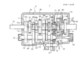
- FIG. 1 shows an outline of a mechanical automatic manual transmission according to an embodiment of the present invention.
- FIG. 2 is a partial perspective view of an oil pipe mounting structure for a transmission according to an embodiment of the present invention.
- FIG. 3 is a front view illustrating an oil pipe mounting structure for a transmission according to an embodiment of the present invention.
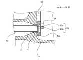
- FIG. 4 is a partial cross-sectional view illustrating an oil pipe mounting structure on the center case side according to one embodiment of the present invention.
- FIG. 5 is a front view illustrating an oil pipe mounting structure on the center case side according to an embodiment of the present invention.
- FIG. 1 shows an outline of a mechanical automatic manual transmission according to an embodiment of the present invention.
- a mechanical automatic manual transmission (hereinafter also referred to as a transmission) 1 includes an input shaft 10, a main shaft 11 arranged coaxially with the input shaft 10, and coaxially with the main shaft 11 on the output side of the main shaft 11.
- the auxiliary transmission 60 arranged, and the counter shaft 12 and the reverse idler shaft 16 arranged in parallel with the input shaft 10 and the main shaft 11 are provided.
- the input main gear 13 is provided on the input shaft 10 so as to be integrally rotatable.
- the main shaft 11 includes, in order from the input side, a first hub 21, a 5th / 9th speed main gear M5, a 3rd / 7th speed main gear M3, a second hub 31, a 2nd / 6th speed main gear M2, a first speed main gear M1, A third hub 41, a reverse main gear MR, a guide piece 53, and a sun gear 61 of the auxiliary transmission 60 are provided.
- the 5-speed / 9-speed main gear M5, 3-speed / 7-speed main gear M3, 2-speed / 6-speed main gear M2, 1-speed main gear M1, and reverse main gear MR are provided on the main shaft 11 so as to be relatively rotatable.
- the second hub 31, the third hub 41, the guide piece 53, and the sun gear 61 are provided on the main shaft 11 so as to be integrally rotatable.
- the auxiliary transmission 60 transmits the rotation of the main shaft 11 to the carrier 63 (output shaft) by switching between the high range and the low range.
- the auxiliary transmission 60 is configured by, for example, a planetary gear mechanism.
- the auxiliary transmission 60 includes a sun gear 61, a plurality of planetary gears 62 disposed around the sun gear 61 so as to mesh with the sun gear 61, and a ring gear 64 formed with internal teeth that mesh with the planetary gear 62.
- a carrier 63 that rotatably supports the plurality of planetary gears 62.
- the output side of the carrier 63 has a cylindrical shape coaxial with the main shaft 11.
- An output side of the ring gear 64 surrounds a cylindrical portion of the carrier 63, and an annular portion 65 that can rotate relative to the carrier 63 is formed.
- a fourth hub 66 is provided in the annular portion 65 so as to be integrally rotatable.
- the main shaft 11 Inside the main shaft 11, it extends in the axial direction and extends in the axial direction to the outer peripheral surface of the main shaft 11 from the axial flow channel 11 a to flow the lubricating oil.
- One or more radial flow paths 11b for discharging from the opening (exit) are formed.
- the radial flow path 11b is formed in each of the fifth speed / 9th speed main gear M5, the third speed / 7th speed main gear M3, the second speed / 6th speed main gear M2, the first speed main gear M1, the reverse main gear MR, and the guide piece 53. It is provided at a position facing the peripheral surface.
- the counter shaft 12 meshes with the input counter gear 14 meshed with the input main gear 13 and the 5th / 9th counter gear C5 and 3rd / 7th main gear M3 meshed with the 5th / 9th main gear M5 in order from the input side.
- a reverse counter gear CR that meshes with the idler gear 17 is provided.
- the input counter gear 14, the 5th / 9th counter gear C5, the 3rd / 7th counter gear C3, the 2nd / 6th counter gear C2, the 1st speed counter gear C1, and the reverse counter gear CR are integrated with the counter shaft 12. It is provided so as to be rotatable. On the output side of the countershaft 12, a countershaft brake 15 for braking the rotation of the countershaft 12 is provided.
- An idler gear 17 is provided on the reverse idler shaft 16 so as to be relatively rotatable.
- the idler gear 17 meshes with the reverse counter gear CR and the reverse main gear MR.
- a first sleeve 22 is attached to the first hub 21 so that it cannot rotate but can move in the axial direction.
- a synchronizer ring may be interposed between the first sleeve 22 and each of the input main gear 13 and a dog gear (not shown) fixed to each of the fifth speed / 9th speed main gear M5.
- a shift fork (not shown) that moves the first sleeve 22 in the axial direction is engaged with the outer circumferential groove of the first sleeve 22.
- a second sleeve 32 is attached to the second hub 31 so as not to rotate but to move in the axial direction.
- a synchronizer ring may be interposed between the second sleeve 32 and a dog gear (not shown) fixed to each of the third speed / 7th speed main gear M3 and the second speed / 6th speed main gear M2.
- a shift fork (not shown) that moves the second sleeve 32 in the axial direction is engaged with the outer circumferential concave groove of the second sleeve 32.
- a third sleeve 42 is attached to the third hub 41 so as not to rotate but to move in the axial direction.
- a synchronizer ring may be interposed between the third sleeve 42 and a dog gear (not shown) fixed to each of the first speed main gear M1 and the reverse main gear MR.
- a shift fork (not shown) that moves the third sleeve 42 in the axial direction is engaged with the outer circumferential concave groove of the third sleeve 42.
- the third sleeve 42 moves in the direction of arrow A in the drawing and is spline-engaged with the dog gear connected to the first-speed main gear M1, the input main gear 13, the input counter gear 14, the first-speed counter gear C1, and the first-speed main gear M1 are passed through.
- power is transmitted to the main shaft 11.
- the range of the sub-transmission 60 is fixedly set to one range (for example, the low range). Therefore, the carrier 63 rotates at the first speed.
- the third sleeve 42 moves in the direction of arrow B in the drawing and is spline-engaged with the dog gear connected to the reverse main gear MR, the input main gear 13, the input counter gear 14, the reverse counter gear CR, the idler gear 17, and the reverse main gear MR are passed through.
- power is transmitted to the main shaft 11.
- the range of the sub-transmission 60 is fixedly set to one range (for example, the low range).
- the carrier 63 rotates in the reverse direction.
- a fourth sleeve 67 is attached to the fourth hub 66 so as not to rotate but to move in the axial direction.
- a synchronizer ring may be interposed between the fourth sleeve 67 and the dog gear of the dog plate 71 and the dog gear fixed to the carrier 63.
- a shift fork (not shown) that moves the fourth sleeve 67 in the axial direction is engaged with the outer circumferential groove of the fourth sleeve 67.
- the fourth sleeve 67 moves in the direction of arrow A in the figure and meshes with the dog gear of the dog plate 71 fixed to the transmission case 2 (for example, the center case 2b), the ring gear 64 is fixed to the transmission case 2.
- the sub-transmission 60 is in the low range. That is, when the main shaft 11 is rotated by the auxiliary transmission 60, the carrier 63 is rotated at a reduction ratio greater than 1.
- the fourth sleeve 67 moves in the direction of the arrow B in the drawing and meshes with a dog gear (not shown) fixed to the carrier 63 by spline, the ring gear 64 and the carrier 63 are fixed so as to rotate together, and the sub-gear is rotated.
- the state of the transmission 60 is in the high range. That is, the main shaft 11 and the carrier 63 are directly connected by the auxiliary transmission 60.
- the transmission case 2 front case 2 a, center case 2 b, rear case 2 c, etc. except for the input side end of the input shaft 10 and the output side end of the carrier 63.
- the transmission case 2 is supplied with lubricating oil (mission oil) for lubricating each part.
- an oil pipe 80 for sucking the lubricating oil stored in the bottom is disposed.
- the oil pipe 80 is connected to an oil pump (not shown), and the lubricating oil sucked through the oil pipe 80 is supplied to, for example, the axial flow path 11 a of the main shaft 11.
- FIG. 2 is a partial perspective view of an oil pipe mounting structure for a transmission according to an embodiment of the present invention. 2 shows a state in which the transmission 1 is viewed from the lower side (from the lower side of the drawing in FIG. 1).
- the oil pipe mounting structure includes an oil pipe 80 and an alignment member 90 for adjusting the position of the oil pipe 80 to a predetermined position.
- the oil pipe 80 is, for example, a metal cylindrical member, and one end is fitted and attached to a hole communicating with an oil pump (not shown) formed in the wall of the front case 2a.
- the oil pipe 80 has a base end portion 80a attached to the wall (first wall portion) of the front case 2a, and a front end portion 80b formed extending from the base end portion 80a.
- the base end portion 80a is formed to extend substantially in the arrow B direction.
- the tip 80b is formed with a suction hole 80c for sucking lubricating oil at the tip.
- the distal end portion 80b is bent so that the suction hole 80c reaches a predetermined position (for example, a position directly below the counter shaft 12 between the 3rd speed / 7th speed counter gear C3 and the 2nd speed / 6th speed counter gear C2). ing.
- a predetermined position for example, a position directly below the counter shaft 12 between the 3rd speed / 7th speed counter gear C3 and the 2nd speed / 6th speed counter gear C2.
- the base end portion 80a of the oil pipe 80 is for restricting the bending direction of the tip end portion 80b in a plane perpendicular to the axial direction of the base end portion 80a so that the suction hole 80c can be disposed at a predetermined position.
- the direction restricting portion 81 is fixed. The regulation of the direction of the bending direction of the distal end portion 80b by the orientation regulating portion 81 will be described later.
- the alignment member 90 is connected to the distal end side of the proximal end portion 80a of the oil pipe 80.
- the alignment member 90 has a length that reaches the mounting hole 4 of the wall (second wall portion) of the center case 2b that faces the wall of the front case 2a (wall to which the oil pipe 80 is mounted).
- the alignment member 90 is attached to the wall of the center case 2b by a cap 93.
- the alignment member 90 is a connection that connects the rod-shaped portion 92 located on the center case 2b side, the portion on the front case 2a side of the rod-shaped portion 92, and the portion on the center case 2b side of the base end portion 80a of the oil pipe 80.
- the rod-shaped part 92 is, for example, a metal cylindrical member (pipe).
- the rod-shaped portion 92 is not limited to a cylindrical shape, and may be a columnar member or a member having another cross-sectional shape.
- the outer diameter of the rod-shaped portion 92 may be substantially the same as the outer diameter of the oil pipe 80.
- the connecting portion 91 is, for example, a member having a circular cross section made of metal.
- the inner diameter of the connecting portion 91 (the inner diameter of the arc of the cross section) may be substantially the same as the outer diameter of the rod-shaped portion 92 and the oil pipe 80.
- the inner peripheral surface of the connecting portion 91 can be brought into close contact with the outer peripheral surfaces of the rod-shaped portion 92 and the oil pipe 80.
- the connecting portion 91, the rod-shaped portion 92, and the oil pipe 80 can be firmly fixed by being connected by bonding, welding, or the like.
- the oil pipe 80 and the alignment member 90 have sufficient rigidity to maintain the following state. That is, the side fixed to the center case 2b of the alignment member 90 in a state where the transmission 1 is being assembled, in which the oil pipe 80 is attached to the front case 2a and the alignment member 90 is not attached to the center case 2b.
- the center case 2b and the front case 2a are attached, the end portion of the center case 2b can be maintained in the vicinity of the position where the attachment hole 4 of the center case 2b is assumed to be located. Thereby, the alignment member 90 can be easily inserted and attached to the attachment hole 4 of the center case 2b.
- FIG. 3 is a front view of an oil pipe mounting structure for a transmission according to an embodiment of the present invention. 3 is a view of the oil pipe mounting structure as viewed from the direction of arrow B in FIG.
- the orientation restricting portion 81 fixed to the oil pipe 80 is attached so as to engage with the side wall of the front case 2a.
- the direction restricting portion 81 restricts the bending direction of the distal end portion 80 b of the oil pipe 80 so that the suction hole 80 c is at a predetermined position below the counter shaft 12. Thereby, it can prevent that the oil pipe 80 rotates centering around an axis
- the suction hole 80c is reliably disposed at a predetermined position below the counter shaft 12 without being aware of the bending direction of the tip 80b of the oil pipe 80. be able to.
- FIG. 4 is a partial cross-sectional view illustrating an oil pipe mounting structure on the center case side according to an embodiment of the present invention.
- a mounting hole 4 for attaching the end of the rod-shaped portion 92 of the alignment member 90 is formed in the wall of the center case 2b (here, the wall facing the wall to which the oil pipe 80 of the front case 2a is mounted).
- the attachment hole 4 is a through hole.
- the attachment hole 4 includes a tapered portion 3 having a tapered shape in which the diameter of the hole on the front case 2a side is widened. The tapered portion 3 guides the end portion of the rod-like portion 92 to an appropriate position of the mounting hole 4 when the front case 2a and the center case 2b are brought close to each other.
- the end of the rod-shaped portion 92 is maintained in the vicinity of the position where the mounting hole 4 of the center case 2b is supposed to be located when the center case 2b and the front case 2a are combined. Therefore, by bringing the center case 2b and the front case 2a close together, the end of the rod-shaped portion 92 can be brought to an appropriate position of the mounting hole 4 without being aware of the position of the tip of the rod-shaped portion 92. Can be inserted.
- the inner diameter of the narrowest part of the mounting hole 4 is longer than the outer diameter of the rod-shaped part 92. Therefore, when the tip of the rod-shaped portion 92 is inserted into the mounting hole 4, a gap exists between the inner peripheral surface of the mounting hole 4 and the inner peripheral surface of the rod-shaped portion 92.
- a cap 93 (an example of an attachment member) is inserted into a gap existing between the attachment hole 4 and the rod-shaped portion 92, and the cap 93 and the rod-shaped portion 92 are fitted in the attachment hole 4.
- the alignment member 90 is attached to the attachment hole 4.
- the cap 93 is thicker than the gap between the mounting hole 4 and the rod-like portion 92, and has a circular pipe portion 93a inserted into the gap and an upper surface portion 93b that closes the end surface of the circular pipe portion 93a. With such a configuration, the cap 93 can attach the alignment member 90 to the attachment hole 4 relatively firmly.
- a cap pressing portion 52a as an example of a movement restricting portion that restricts the movement of the cap 93 in the arrow B direction and prevents the cap 93 from falling off is disposed. Yes.
- the cap retainer 52a is formed in a bearing retainer 52 that is fixed to the center case 2b by a bolt 54.
- FIG. 5 is a front view illustrating an oil pipe mounting structure on the center case side according to an embodiment of the present invention.
- FIG. 5 is a view of the oil pipe mounting structure viewed from the direction of arrow B in FIG.
- the bearing retainer 52 has an approximately eight-letter shape, and supports the respective bearings 51 that rotatably support the main shaft 11 and the counter shaft 12 on the center case 2b. On the left side below the bearing retainer 52, a cap presser 52a that restricts the movement of the cap 93 is formed.
- the bearing retainer 52 is integrally formed by a predetermined mold, for example. Thus, since the bearing retainer 52 is integrally molded, it is not necessary to prepare the cap pressing portion 52a as another configuration, and the number of parts in the transmission 1 can be prevented from increasing. Moreover, since the operation
- the oil pipe 80 is aligned by the alignment member 90 that is connected to the oil pipe 80 and mounted to the center case 2b. It can be done easily and appropriately. Further, since the alignment member 90 can be easily attached to the center case 2b, the work load on the operator can be reduced.
- the alignment member 90 a member in which two members are fixed is used as the alignment member 90.
- the present invention is not limited to this, and may be a single member. Any member that has one end connected and the other end attached to the wall may be used.
- the cross-sectional shape used the arc-shaped member as the connection part 91 of the alignment member 90 is not restricted to this, Other arbitrary shapes, such as a V-shaped cross section, are not limited to this. In short, any member that can appropriately connect the oil pipe 90 and the rod-shaped portion 92 may be used.
- the oil pipe mounting structure for a transmission according to the present invention is useful in that an oil pipe for sucking lubricating oil can be easily and appropriately arranged.
Landscapes
- Engineering & Computer Science (AREA)
- General Engineering & Computer Science (AREA)
- Mechanical Engineering (AREA)
- General Details Of Gearings (AREA)
Abstract
変速機ケース2内に溜まったオイルを吸引するためのオイルパイプ80と、オイルパイプ80の基端部80aが取り付けられるフロントケース2aの壁と、フロントケース2aと対向して設けられるセンターケース2bの壁と、一端がオイルパイプ80に接続されるとともに、他端がセンターケース2bの壁の所定の取付孔4に取り付けられることにより、オイルパイプ80の位置を所定位置に合わせる位置合わせ部材90と、を有するように構成する。
Description
本発明は、変速機に関し、特に、変速機における潤滑油を吸引するオイルパイプの取付構造に関する。
従来、変速機においては、複数のギヤ等に発生する摩擦を低減するために変速機の各部に潤滑油を供給し、変速機ケースの下部に溜まった潤滑油をオイルパイプによって吸引し、変速機の各部に再び供給するようにしている。例えば、変速機におけるオイルの吸込みパイプをオイルポンプの吸込み口に取り付ける技術が知られている(特許文献1参照)。
変速機ケースの下部に溜まった潤滑油を適切に吸引するためには、吸引するためのオイルパイプを適切な位置に配置することが必要である。
オイルパイプは、変速機ケースの内部に配置されるので、目視により確認し辛い位置にある場合が多く、変速機の組み付け時に、オイルパイプを適切な位置に取り付けることが困難である。また、適切な位置に配置するために、オイルパイプを変速機ケースの多くの位置に固定するようにすると、取り付けに非常に手間がかかる。
本発明は、上記課題に鑑みなされたものであり、その目的は、潤滑油を吸引するオイルパイプを容易且つ適切に配置することのできる技術を提供することにある。
上述の目的を達成するため、本発明の一観点に係る変速機のオイルパイプ取付構造は、変速機ケース内に溜まったオイルを吸引するためのオイルパイプと、オイルパイプの基端部が取り付けられる第1壁部と、第1壁部と対向して設けられる第2壁部と、一端がオイルパイプに接続されるとともに、他端が第2壁部の所定の取付孔に取り付けられることにより、オイルパイプの位置を所定位置に合わせる位置合わせ部材と、を有する。
上記変速機のオイルパイプ取付構造において、位置合わせ部材は、第2壁部側に位置し、円筒形状または円柱形状の棒状部と、棒状部とオイルパイプとの少なくとも一部を接続する接続部とを有するようにしてもよい。
また、上記変速機のオイルパイプ取付構造において、接続部は、断面が円弧形状の部材であってもよい。
また、上記変速機のオイルパイプ取付構造において、第2壁部の取付孔は、第1壁部側が広くなっているテーパ形状を有していてもよい。
また、上記変速機のオイルパイプ取付構造において、オイルパイプ及び位置合わせ部材は、位置合わせ部材が第2壁部に取り付けられていない状態において、第2壁部に取り付けられている際に近い状態を維持可能な剛性を有していてもよい。
また、上記変速機のオイルパイプ取付構造において、取付孔は、貫通孔であり、取付孔の最も狭い部分の内径は、棒状部の外径よりも長く、棒状部の外側と、取付孔との隙間を埋めるための円筒部を有し、第1壁部と反対側から隙間を埋めるように円筒部が挿入されることにより、棒状部を取付孔に取り付ける取付部材をさらに有するようにしてもよい。また、上記変速機のオイルパイプ取付構造において、取付部材の第1壁部と反対側への移動を規制する移動規制部をさら有するようにしてもよい。
また、上記変速機のオイルパイプ取付構造において、オイルパイプは、先端部が屈曲しており、オイルパイプに接続され、オイルパイプの先端部が所定の方向に向くように、先端部の向きを規制する向き規制部をさらに有するようにしてもよい。
本発明によると、潤滑油を吸引するオイルパイプを容易且つ適切に配置することができる。
以下、添付図面に基づいて、本発明の一実施形態に係るオイルパイプ取付構造を有する変速機について説明する。同一の部品には同一の符号を付してあり、それらの名称および機能も同じである。したがって、それらについての詳細な説明は繰返さない。
図1は、本発明の一実施形態に係る機械式自動マニュアル変速機の概要を示す。
機械式自動マニュアル変速機(以下、変速機とも記載する)1は、インプットシャフト10と、インプットシャフト10と同軸に配置されたメインシャフト11と、メインシャフト11の出力側にメインシャフト11と同軸に配置された副変速機60と、インプットシャフト10及びメインシャフト11と平行に配置されたカウンタシャフト12及びリバースアイドラシャフト16と、を備えている。
インプットシャフト10には、インプットメインギヤ13が一体回転可能に設けられている。メインシャフト11には、入力側から順に、第1ハブ21、5速/9速メインギヤM5、3速/7速メインギヤM3、第2ハブ31、2速/6速メインギヤM2、1速メインギヤM1、第3ハブ41、リバースメインギヤMR、ガイドピース53、副変速機60のサンギヤ61が設けられている。5速/9速メインギヤM5、3速/7速メインギヤM3、2速/6速メインギヤM2、1速メインギヤM1、及びリバースメインギヤMRは、メインシャフト11に相対回転可能に設けられ、第1ハブ21、第2ハブ31、第3ハブ41、ガイドピース53、及びサンギヤ61はメインシャフト11に一体回転可能に設けられている。
副変速機60は、メインシャフト11の回転をハイと、ローの2つのレンジの何れかに切り替えてキャリア63(アウトプットシャフト)に伝達する。副変速機60は、例えば、遊星歯車機構により構成される。具体的には、副変速機60は、サンギヤ61と、サンギヤ61と噛合するようにサンギヤ61の周囲に配置された複数のプラネタリギヤ62と、プラネタリギヤ62と噛合する内歯が形成されたリングギヤ64と、複数のプラネタリギヤ62を回転可能に支持するキャリア63とを有する。キャリア63の出力側は、メインシャフト11と同軸の円柱形状となっている。リングギヤ64の出力側は、キャリア63の円柱形状の部分を取り囲み、キャリア63と相対回転可能な円環部65が形成されている。円環部65には、第4ハブ66が一体回転可能に設けられている。
メインシャフト11の内部には、軸方向に延び、潤滑油を流すための軸方向流路11aと、軸方向流路11aからメインシャフト11の外周面に径方向に延び、潤滑油を外周面の開孔(出口)から放出するための1以上の径方向流路11bが形成されている。径方向流路11bは、例えば、5速/9速メインギヤM5、3速/7速メインギヤM3、2速/6速メインギヤM2、1速メインギヤM1、リバースメインギヤMR、及びガイドピース53のそれぞれの内周面に対向する位置に設けられている。
カウンタシャフト12には、入力側から順に、インプットメインギヤ13と噛合するインプットカウンタギヤ14、5速/9速メインギヤM5と噛合する5速/9速カウンタギヤC5、3速/7速メインギヤM3と噛合する3速/7速カウンタギヤC3、2速/6速メインギヤM2と噛合する2速/6速カウンタギヤC2、1速メインギヤM1と噛合する1速カウンタギヤC1、リバースメインギヤMRと噛合する後述するアイドラギヤ17と噛合するリバースカウンタギヤCRが設けられている。インプットカウンタギヤ14、5速/9速カウンタギヤC5、3速/7速カウンタギヤC3、2速/6速カウンタギヤC2、1速カウンタギヤC1、及びリバースカウンタギヤCRは、カウンタシャフト12に一体回転可能に設けられている。カウンタシャフト12の出力側には、カウンタシャフト12の回転を制動するためのカウンタシャフトブレーキ15が設けられている。
リバースアイドラシャフト16には、アイドラギヤ17が相対回転可能に設けられている。アイドラギヤ17は、リバースカウンタギヤCRと、リバースメインギヤMRと噛合している。
第1ハブ21には、回転不能且つ軸方向に移動可能に第1スリーブ22が取り付けられている。なお、第1スリーブ22と、インプットメインギヤ13及び5速/9速メインギヤM5のそれぞれに固定されている図示しないドグギヤとのそれぞれの間にシンクロナイザリングが介装されていてもよい。第1スリーブ22の外周凹溝には、第1スリーブ22を軸方向に移動させる図示しないシフトフォークが係合されている。
第1スリーブ22が図中矢印A方向に移動してインプットメインギヤ13のドグギヤとスプライン噛合すると、インプットシャフト10とメインシャフト11とが直結されて動力が伝達される。この結果、副変速機60のレンジがローに設定されている場合には、キャリア63は、4速相当で回転し、副変速機60のレンジがハイに設定されている場合には、キャリア63は、8速相当で回転する。
第1スリーブ22が図中矢印B方向に移動して5速/9速メインギヤM5に接続されているドグギヤとスプライン噛合すると、インプットメインギヤ13、インプットカウンタギヤ14、5速/9速カウンタギヤC5、5速/9速メインギヤM5、を介してメインシャフト11に動力が伝達される。この結果、副変速機60のレンジがローに設定されている場合には、キャリア63は、5速相当で回転し、副変速機60のレンジがハイに設定されている場合には、キャリア63は、9速相当で回転する。
第2ハブ31には、回転不能且つ軸方向に移動可能に第2スリーブ32が取り付けられている。なお、第2スリーブ32と、3速/7速メインギヤM3及び2速/6速メインギヤM2のそれぞれに固定されている図示しないドグギヤとのそれぞれの間にシンクロナイザリングが介装されていてもよい。第2スリーブ32の外周凹溝には、第2スリーブ32を軸方向に移動させる図示しないシフトフォークが係合されている。
第2スリーブ32が図中矢印A方向に移動して3速/7速メインギヤM3に接続されているドグギヤとスプライン噛合すると、インプットメインギヤ13、インプットカウンタギヤ14、3速/7速カウンタギヤC3、3速/7速メインギヤM3を介して動力がメインシャフト11に伝達される。この結果、副変速機60のレンジがローに設定されている場合には、キャリア63は、3速相当で回転し、副変速機60のレンジがハイに設定されている場合には、キャリア63は、7速相当で回転する。
第2スリーブ32が図中矢印B方向に移動して2速/6速メインギヤM2に接続されているドグギヤとスプライン噛合すると、インプットメインギヤ13、インプットカウンタギヤ14、2速/6速カウンタギヤC2、2速/6速メインギヤM2を介して、メインシャフト11に動力が伝達される。この結果、副変速機60のレンジがローに設定されている場合には、キャリア63は、2速相当で回転し、副変速機60のレンジがハイに設定されている場合には、キャリア63は、6速相当で回転する。
第3ハブ41には、回転不能且つ軸方向に移動可能に第3スリーブ42が取り付けられている。なお、第3スリーブ42と、1速メインギヤM1及びリバースメインギヤMRのそれぞれに固定されている図示しないドグギヤとのそれぞれの間にシンクロナイザリングが介装されていてもよい。第3スリーブ42の外周凹溝には、第3スリーブ42を軸方向に移動させる図示しないシフトフォークが係合されている。
第3スリーブ42が図中矢印A方向に移動して1速メインギヤM1に接続されているドグギヤとスプライン噛合すると、インプットメインギヤ13、インプットカウンタギヤ14、1速カウンタギヤC1、1速メインギヤM1を介して動力がメインシャフト11に伝達される。本実施形態の変速機1では、1速の変速段が選択される場合には、副変速機60のレンジは、一方のレンジ(例えば、ローのレンジ)に固定的に設定されるようになっているので、キャリア63は、1速相当で回転する。
第3スリーブ42が図中矢印B方向に移動してリバースメインギヤMRに接続されているドグギヤとスプライン噛合すると、インプットメインギヤ13、インプットカウンタギヤ14、リバースカウンタギヤCR、アイドラギヤ17、リバースメインギヤMRを介して、メインシャフト11に動力が伝達される。本実施形態の変速機1では、後退(リバース)の変速段が選択される場合には、副変速機60のレンジは、一方のレンジ(例えば、ローのレンジ)に固定的に設定されるようになっており、キャリア63は、逆回転する。
第4ハブ66には、回転不能且つ軸方向に移動可能に第4スリーブ67が取り付けられている。なお、第4スリーブ67と、ドグプレート71のドグギヤ及びキャリア63に固定されているドグギヤとのそれぞれの間にシンクロナイザリングが介装されていてもよい。第4スリーブ67の外周凹溝には、第4スリーブ67を軸方向に移動させる図示しないシフトフォークが係合されている。
第4スリーブ67が図中矢印A方向に移動して、変速機ケース2(例えば、センターケース2b)に固定されているドグプレート71のドグギヤとスプライン噛合すると、リングギヤ64が変速機ケース2に固定され、副変速機60の状態がローのレンジとなる。すなわち、副変速機60によって、メインシャフト11が回転すると、キャリア63は1より大きい減速比で回転する。
一方、第4スリーブ67が図中矢印B方向に移動して、キャリア63に固定されている図示しないドグギヤとスプライン噛合すると、リングギヤ64と、キャリア63とが一体回転するように固定されて、副変速機60の状態がハイのレンジとなる。すなわち、副変速機60によって、メインシャフト11とキャリア63とが直結される。
変速機1においては、基本的には、インプットシャフト10の入力側端部と、キャリア63の出力側端部とを除いて、変速機ケース2(フロントケース2a、センターケース2b、リアケース2c等)内に収容される。変速機ケース2の内部には、各部を潤滑させるための潤滑油(ミッションオイル)が供給されている。
変速機ケース2の底部近傍には、底部に貯留している潤滑油を吸引するためのオイルパイプ80が配置されている。オイルパイプ80は、図示しないオイルポンプに接続されており、オイルパイプ80を介して吸引された潤滑油は、例えば、メインシャフト11の軸方向流路11aに供給される。
次に、変速機1におけるオイルパイプ取付構造について説明する。
図2は、本発明の一実施形態に係る変速機のオイルパイプ取付構造の部分斜視図である。なお、図2は、変速機1を下側から(図1における紙面下側から)見た状態を示している。
オイルパイプ取付構造は、オイルパイプ80と、オイルパイプ80の位置を所定位置に合わせるための位置合わせ部材90とを有する。
オイルパイプ80は、例えば、金属製の円筒部材であり、フロントケース2aの壁に形成された図示しないオイルポンプに連通する穴に一端が嵌合されて取り付けられている。オイルパイプ80は、フロントケース2aの壁(第1壁部)に取り付けられている基端部80aと、基端部80aから延びて形成された先端部80bとを有する。基端部80aは、略矢印B方向に延びて形成されている。先端部80bは、先端に潤滑油を吸引する吸引孔80cが形成されている。先端部80bは、吸引孔80cが所定の位置(例えば、3速/7速カウンタギヤC3及び2速/6速カウンタギヤC2の間のカウンタシャフト12の直下の位置)に到達するように屈曲している。
オイルパイプ80の基端部80aには、基端部80aの軸方向に垂直な面内における先端部80bの屈曲方向を、吸引孔80cを所定の位置に配置できるような向きに規制するための向き規制部81が固定されている。向き規制部81による先端部80bの屈曲方向の向きの規制については後述する。
位置合わせ部材90は、オイルパイプ80の基端部80aの先端側に接続されている。位置合わせ部材90は、フロントケース2aの壁(オイルパイプ80が取り付けられている壁)に対向するセンターケース2bの壁(第2壁部)の取付孔4に到達する長さを有している。位置合わせ部材90は、キャップ93により、センターケース2bの壁に取り付けられる。このように位置合わせ部材90がセンターケース2bの壁に取り付けられると、オイルパイプ80は、一端がフロントケース2aの壁に取り付けられ、他端側がセンターケース2bに取り付けられた位置合わせ部材90に接続されているので、自ずとその位置が所定の位置に合わされることとなる。なお、位置合わせ部材90のセンターケース2bへの取り付けについては後述する。
位置合わせ部材90は、センターケース2b側に位置する棒状部92と、棒状部92のフロントケース2a側の部分と、オイルパイプ80の基端部80aのセンターケース2b側の部分とを接続する接続部91とを有する。棒状部92は、例えば、金属製の円筒形状の部材(パイプ)である。なお、棒状部92は、円筒形状に限られず、円柱形状の部材や、他の断面形状の部材であってもよい。棒状部92の外径は、例えば、オイルパイプ80の外径とほぼ同じであってもよい。
接続部91は、例えば、金属製の断面が円弧形状の部材である。接続部91の内径(断面の円弧の内側の径)は、棒状部92及びオイルパイプ80の外径とほぼ同じであってもよい。このように、接続部91の内径を棒状部92及びオイルパイプ80の外径とほぼ同じにすると、接続部91の内周面を、棒状部92及びオイルパイプ80の外周面に密着させることができ、接続部91と棒状部92及びオイルパイプ80とを接着、溶接等により接続することにより、強固に固定することができる。
本実施形態では、オイルパイプ80と、位置合わせ部材90とは、次のような状態を維持するのに十分な剛性を有している。すなわち、オイルパイプ80がフロントケース2aに取り付けられ、位置合わせ部材90がセンターケース2bに取り付けられていない、変速機1の組み立て途中の状態において、位置合わせ部材90のセンターケース2bに固定される側の端部を、センターケース2bとフロントケース2aとを取り付ける際にセンターケース2bの取付孔4が位置すると想定される位置の近傍に維持させることができる。これにより、位置合わせ部材90をセンターケース2bの取付孔4に容易に挿入して取り付けることができる。
次に、向き規制部81による先端部80bの屈曲方向の向きの規制について説明する。
図3は、本発明の一実施形態に係る変速機のオイルパイプ取付構造の正面図である。図3は、図2における矢印B方向側からオイルパイプ取付構造を見た図である。
オイルパイプ80に固定されている向き規制部81は、フロントケース2aの側面側の壁に係合するように取り付けられる。向き規制部81は、オイルパイプ80の先端部80bの屈曲方向が、吸引孔80cがカウンタシャフト12の下方の所定の位置になるように規制する。これにより、オイルパイプ80が軸を中心に回転してしまうことを防止できる。
これにより、位置合わせ部材90をセンターケース2bに取り付ける際に、オイルパイプ80の先端部80bの屈曲方向を意識せずとも、吸引孔80cをカウンタシャフト12の下方の所定の位置に確実に配置することができる。
図4は、本発明の一実施形態に係るセンターケース側におけるオイルパイプ取付構造を説明する部分断面図である。
センターケース2bの壁(ここでは、フロントケース2aのオイルパイプ80が取り付けられている壁に対向している壁)には、位置合わせ部材90の棒状部92の端部を取り付ける取付孔4が形成されている。取付孔4は、貫通孔となっている。取付孔4は、フロントケース2a側の孔の径が広くなっているテーパ形状のテーパ部3を有する。このテーパ部3は、フロントケース2aと、センターケース2bとを組み合わせるために近づけた場合に、棒状部92の端部を取付孔4の適切な位置に案内する。
本実施形態では、上述のように、棒状部92の端部を、センターケース2bとフロントケース2aとを組み合わせる際に、センターケース2bの取付孔4が位置すると想定される位置の近傍に維持させることができるので、センターケース2bとフロントケース2aとを組み合わせるために近づけることにより、棒状部92の先端の位置を意識しなくても、棒状部92の端部を取付孔4の適切な位置に挿入することができる。
取付孔4の最も狭い部分の内径は、棒状部92の外径よりも長くなっている。したがって、取付孔4に棒状部92の先端部が挿入された場合には、取付孔4の内周面と棒状部92の内周面との間には、隙間が存在する。
本実施形態では、取付孔4と棒状部92との間に存在する隙間に対してキャップ93(取付部材の一例)を挿入し、キャップ93と棒状部92とを取付孔4において嵌合することにより、位置合わせ部材90を取付孔4に取り付けている。
キャップ93は、取付孔4と棒状部92との隙間よりも厚く、この隙間に挿入される円管部93aと、円管部93aの端面を塞ぐ上面部93bとを有する。このような構成により、キャップ93は、比較的強固に位置合わせ部材90を取付孔4に取り付けることができる。
キャップ93の上面部93bの矢印B方向側には、キャップ93の矢印B方向への移動を規制して、キャップ93の脱落を防止する移動規制部の一例としてのキャップ押え部52aが配置されている。キャップ押え部52aは、センターケース2bにボルト54により固定されるベアリングリテーナ52に形成されている。
図5は、本発明の一実施形態に係るセンターケース側におけるオイルパイプ取付構造を説明する正面図である。図5は、図4における矢印B方向側からオイルパイプ取付構造を見た図である。
ベアリングリテーナ52は、略8の字状であり、メインシャフト11及びカウンタシャフト12のそれぞれを回転自在に支持するそれぞれのベアリング51をセンターケース2bに支持する。ベアリングリテーナ52の下方の左側には、キャップ93の移動を規制するキャップ押え部52aが形成されている。ベアリングリテーナ52は、例えば、所定の金型によって一体成型される。このように、ベアリングリテーナ52は、一体成型されるので、キャップ押え部52aを別の構成として用意する必要がなく、変速機1における部品点数を増加させずに済む。また、キャップ押え部52aが形成されていてもベアリングリテーナ52を取り付ける作業は、変わらないので、作業者への負荷は増加しない。
以上説明したように、本実施形態に係る変速機1のオイルパイプ取付構造によると、オイルパイプ80に接続されるとともに、センターケース2bに取り付けられる位置合わせ部材90により、オイルパイプ80の位置合わせを容易且つ適切に行うことができる。また、センターケース2bに、位置合わせ部材90を容易に取り付けることができるので、作業者への作業負荷を低減することができる。
なお、本発明は、上述の実施形態に限定されるものではなく、本発明の趣旨を逸脱しない範囲で、適宜変形して実施することが可能である。
例えば、上記実施形態では、位置合わせ部材90として、2つの部材を固定した部材を用いていたが、本発明はこれに限られず、1つの部材であってもよく、要は、オイルパイプ80に一端が接続され、他端が壁に取り付けられるようにした部材であればよい。
また、上記実施形態では、位置合わせ部材90の接続部91として、断面形状が円弧形状の部材を用いていたが、本発明はこれに限られず、断面がV字形状等の他の任意の形状の部材であってもよく、要は、オイルパイプ90と棒状部92とを適切に接続できる部材であればよい。
本出願は、2015年06月18日付で出願された日本国特許出願(特願2015-122808)に基づくものであり、その内容はここに参照として取り込まれる。
本発明の変速機のオイルパイプ取付構造は、潤滑油を吸引するオイルパイプを容易且つ適切に配置することができるという点において有用である。
1 変速機
2 変速機ケース
2a フロントケース
2b センターケース
2c リアケース
3 テーパ部
4 取付孔
10 インプットシャフト
11 メインシャフト
11a 軸方向流路
11b 径方向流路
12 カウンタシャフト
13 インプットメインギヤ
14 インプットカウンタギヤ
15 カウンタシャフトブレーキ
16 リバースアイドラシャフト
17 アイドラギヤ
21 第1ハブ
22 第1スリーブ
31 第2ハブ
32 第2スリーブ
41 第3ハブ
42 第3スリーブ
51 ベアリング
52 ベアリングリテーナ
52a キャップ押え部
53 ガイドピース
60 副変速機
61 サンギヤ
62 プラネタリギヤ
63 キャリア
64 リングギヤ
65 円環部
66 第4ハブ
67 第4スリーブ
71 ドグプレート
80 オイルパイプ
80a 基端部
80b 先端部
80c 吸引孔
81 向き規制部
90 位置合わせ部材
91 接続部
92 棒状部
93 キャップ
93a 円筒部
93b 上面部
M1 1速メインギヤ
M2 2速/6速メインギヤ
M3 3速/7速メインギヤ
M5 5速/9速メインギヤ
MR リバースメインギヤ
C1 1速カウンタギヤ
C2 2速/6速カウンタギヤ
C3 3速/7速カウンタギヤ
C5 5速/9速カウンタギヤ
CR リバースカウンタギヤ
2 変速機ケース
2a フロントケース
2b センターケース
2c リアケース
3 テーパ部
4 取付孔
10 インプットシャフト
11 メインシャフト
11a 軸方向流路
11b 径方向流路
12 カウンタシャフト
13 インプットメインギヤ
14 インプットカウンタギヤ
15 カウンタシャフトブレーキ
16 リバースアイドラシャフト
17 アイドラギヤ
21 第1ハブ
22 第1スリーブ
31 第2ハブ
32 第2スリーブ
41 第3ハブ
42 第3スリーブ
51 ベアリング
52 ベアリングリテーナ
52a キャップ押え部
53 ガイドピース
60 副変速機
61 サンギヤ
62 プラネタリギヤ
63 キャリア
64 リングギヤ
65 円環部
66 第4ハブ
67 第4スリーブ
71 ドグプレート
80 オイルパイプ
80a 基端部
80b 先端部
80c 吸引孔
81 向き規制部
90 位置合わせ部材
91 接続部
92 棒状部
93 キャップ
93a 円筒部
93b 上面部
M1 1速メインギヤ
M2 2速/6速メインギヤ
M3 3速/7速メインギヤ
M5 5速/9速メインギヤ
MR リバースメインギヤ
C1 1速カウンタギヤ
C2 2速/6速カウンタギヤ
C3 3速/7速カウンタギヤ
C5 5速/9速カウンタギヤ
CR リバースカウンタギヤ
Claims (8)
- 変速機ケース内に溜まったオイルを吸引するためのオイルパイプと、
前記オイルパイプの基端部が取り付けられる第1壁部と、
前記第1壁部と対向して設けられる第2壁部と、
一端が前記オイルパイプに接続されるとともに、他端が前記第2壁部の所定の取付孔に取り付けられることにより、前記オイルパイプの位置を所定位置に合わせる位置合わせ部材と、を有する変速機のオイルパイプ取付構造。 - 前記位置合わせ部材は、前記第2壁部側に位置し、円筒形状または円柱形状の棒状部と、前記棒状部と前記オイルパイプとの少なくとも一部を接続する接続部とを有する請求項1に記載の変速機のオイルパイプ取付構造。
- 前記接続部は、断面が円弧形状の部材である請求項2に記載の変速機のオイルパイプ取付構造。
- 前記第2壁部の前記取付孔は、第1壁部側が広くなっているテーパ形状を有する請求項1から3の何れか一項に記載の変速機のオイルパイプ取付構造。
- 前記オイルパイプ及び前記位置合わせ部材とは、前記位置合わせ部材が前記第2壁部に取り付けられていない状態において、前記第2壁部に取り付けられている際に近い状態を維持可能な剛性を有する請求項4に記載の変速機のオイルパイプ取付構造。
- 前記取付孔は、貫通孔であり、前記取付孔の最も狭い部分の内径は、前記棒状部の外径よりも長く、
前記棒状部の外側と、前記取付孔との隙間を埋めるための円筒部を有し、前記第1壁部と反対側から前記隙間を埋めるように前記円筒部が挿入されることにより、前記棒状部を前記取付孔に取り付ける取付部材をさらに有する請求項1から5の何れか一項に記載の変速機のオイルパイプ取付構造。 - 前記取付部材の前記第1壁部と反対側への移動を規制する移動規制部をさらに有する請求項6に記載の変速機のオイルパイプ取付構造。
- 前記オイルパイプは、先端部が屈曲しており、
前記オイルパイプに接続され、前記オイルパイプの前記先端部が所定の方向に向くように、前記先端部の向きを規制する向き規制部をさらに有する請求項1から請求項7の何れか一項に記載の変速機のオイルパイプ取付構造。
Applications Claiming Priority (2)
| Application Number | Priority Date | Filing Date | Title |
|---|---|---|---|
| JP2015122808A JP6596960B2 (ja) | 2015-06-18 | 2015-06-18 | 変速機のオイルパイプ取付構造 |
| JP2015-122808 | 2015-06-18 |
Publications (1)
| Publication Number | Publication Date |
|---|---|
| WO2016204191A1 true WO2016204191A1 (ja) | 2016-12-22 |
Family
ID=57545988
Family Applications (1)
| Application Number | Title | Priority Date | Filing Date |
|---|---|---|---|
| PCT/JP2016/067838 Ceased WO2016204191A1 (ja) | 2015-06-18 | 2016-06-15 | 変速機のオイルパイプ取付構造 |
Country Status (2)
| Country | Link |
|---|---|
| JP (1) | JP6596960B2 (ja) |
| WO (1) | WO2016204191A1 (ja) |
Citations (9)
| Publication number | Priority date | Publication date | Assignee | Title |
|---|---|---|---|---|
| JPS59146605U (ja) * | 1983-03-22 | 1984-10-01 | 三裕理工合資会社 | めおと鋲 |
| JPH04106552U (ja) * | 1991-02-27 | 1992-09-14 | 栃木富士産業株式会社 | 潤滑装置 |
| JPH07229554A (ja) * | 1994-02-18 | 1995-08-29 | Hino Motors Ltd | 変速機の潤滑オイル循環装置 |
| JP2002340153A (ja) * | 2001-05-22 | 2002-11-27 | Suzuki Motor Corp | 自動変速機のオイルクーラ配管構造 |
| JP2004270819A (ja) * | 2003-03-10 | 2004-09-30 | Yanmar Agricult Equip Co Ltd | トランスミッションハウジング構造 |
| JP2010254287A (ja) * | 2009-04-02 | 2010-11-11 | Mitsubishi Aircraft Corp | 耐雷ファスナ、キャップ、耐雷ファスナの取り付け方法 |
| JP2011224837A (ja) * | 2010-04-16 | 2011-11-10 | Kaga Sangyo Co Ltd | 成形方法 |
| JP2011247397A (ja) * | 2010-05-31 | 2011-12-08 | Jatco Ltd | オイルポンプ装置 |
| JP2012023812A (ja) * | 2010-07-12 | 2012-02-02 | Toyota Motor Corp | 動力装置 |
-
2015
- 2015-06-18 JP JP2015122808A patent/JP6596960B2/ja active Active
-
2016
- 2016-06-15 WO PCT/JP2016/067838 patent/WO2016204191A1/ja not_active Ceased
Patent Citations (9)
| Publication number | Priority date | Publication date | Assignee | Title |
|---|---|---|---|---|
| JPS59146605U (ja) * | 1983-03-22 | 1984-10-01 | 三裕理工合資会社 | めおと鋲 |
| JPH04106552U (ja) * | 1991-02-27 | 1992-09-14 | 栃木富士産業株式会社 | 潤滑装置 |
| JPH07229554A (ja) * | 1994-02-18 | 1995-08-29 | Hino Motors Ltd | 変速機の潤滑オイル循環装置 |
| JP2002340153A (ja) * | 2001-05-22 | 2002-11-27 | Suzuki Motor Corp | 自動変速機のオイルクーラ配管構造 |
| JP2004270819A (ja) * | 2003-03-10 | 2004-09-30 | Yanmar Agricult Equip Co Ltd | トランスミッションハウジング構造 |
| JP2010254287A (ja) * | 2009-04-02 | 2010-11-11 | Mitsubishi Aircraft Corp | 耐雷ファスナ、キャップ、耐雷ファスナの取り付け方法 |
| JP2011224837A (ja) * | 2010-04-16 | 2011-11-10 | Kaga Sangyo Co Ltd | 成形方法 |
| JP2011247397A (ja) * | 2010-05-31 | 2011-12-08 | Jatco Ltd | オイルポンプ装置 |
| JP2012023812A (ja) * | 2010-07-12 | 2012-02-02 | Toyota Motor Corp | 動力装置 |
Also Published As
| Publication number | Publication date |
|---|---|
| JP6596960B2 (ja) | 2019-10-30 |
| JP2017008983A (ja) | 2017-01-12 |
Similar Documents
| Publication | Publication Date | Title |
|---|---|---|
| CN101852273B (zh) | 手动变速器 | |
| US8037780B2 (en) | Discrete-ratio gearbox for motor vehicle | |
| US9303732B2 (en) | Automated manual transmission for vehicle | |
| CN110319155B (zh) | 七挡双离合变速器及车辆 | |
| CN102177364B (zh) | 用于双离合变速器的能被切换的双联齿轮以及双离合变速器 | |
| US11002340B2 (en) | Automatic transmission | |
| KR20110126111A (ko) | 듀얼 클러치식 자동 변속기 | |
| US20050090363A1 (en) | Automatic transmission | |
| JP2010190289A (ja) | 変速機およびその製造方法 | |
| JP6596960B2 (ja) | 変速機のオイルパイプ取付構造 | |
| JP4970395B2 (ja) | 車両用自動変速機の潤滑構造 | |
| WO2016204200A1 (ja) | 変速機 | |
| EP3002481B1 (en) | Shifter gear | |
| JP4624910B2 (ja) | 変速機 | |
| US6513400B2 (en) | Manual transmission | |
| JP6578763B2 (ja) | 変速機のドグプレート取付構造 | |
| EP1939477B1 (en) | Transmission | |
| JP6416642B2 (ja) | 変速機 | |
| JP2017075640A (ja) | 部材取付構造体 | |
| JP6361632B2 (ja) | 変速機の潤滑構造 | |
| CN107709846A (zh) | 换挡装置 | |
| KR101628721B1 (ko) | 자동 변속기 | |
| JP5862548B2 (ja) | 手動変速機の組立方法 | |
| KR102126230B1 (ko) | 차량용 자동변속기 | |
| JP2018096484A (ja) | 変速機 |
Legal Events
| Date | Code | Title | Description |
|---|---|---|---|
| 121 | Ep: the epo has been informed by wipo that ep was designated in this application |
Ref document number: 16811665 Country of ref document: EP Kind code of ref document: A1 |
|
| NENP | Non-entry into the national phase |
Ref country code: DE |
|
| 122 | Ep: pct application non-entry in european phase |
Ref document number: 16811665 Country of ref document: EP Kind code of ref document: A1 |