WO2016203750A1 - Procédé de transmission, procédé de réception, dispositif de transmission, et dispositif de réception - Google Patents
Procédé de transmission, procédé de réception, dispositif de transmission, et dispositif de réception Download PDFInfo
- Publication number
- WO2016203750A1 WO2016203750A1 PCT/JP2016/002836 JP2016002836W WO2016203750A1 WO 2016203750 A1 WO2016203750 A1 WO 2016203750A1 JP 2016002836 W JP2016002836 W JP 2016002836W WO 2016203750 A1 WO2016203750 A1 WO 2016203750A1
- Authority
- WO
- WIPO (PCT)
- Prior art keywords
- transmission
- data symbol
- time
- symbol group
- data
- Prior art date
Links
- 230000005540 biological transmission Effects 0.000 title claims abstract description 1126
- 238000000034 method Methods 0.000 title claims abstract description 564
- 238000012545 processing Methods 0.000 claims description 105
- 230000008859 change Effects 0.000 description 328
- 238000012937 correction Methods 0.000 description 153
- 239000000969 carrier Substances 0.000 description 152
- 230000008707 rearrangement Effects 0.000 description 75
- 230000010287 polarization Effects 0.000 description 56
- 238000003780 insertion Methods 0.000 description 54
- 230000037431 insertion Effects 0.000 description 54
- 238000010586 diagram Methods 0.000 description 51
- 238000013507 mapping Methods 0.000 description 40
- 238000004891 communication Methods 0.000 description 36
- 230000006870 function Effects 0.000 description 35
- 230000000694 effects Effects 0.000 description 29
- 230000014509 gene expression Effects 0.000 description 25
- 230000008901 benefit Effects 0.000 description 24
- 238000001514 detection method Methods 0.000 description 20
- 238000012966 insertion method Methods 0.000 description 20
- 238000006243 chemical reaction Methods 0.000 description 18
- 230000009467 reduction Effects 0.000 description 14
- 238000013461 design Methods 0.000 description 12
- 230000010363 phase shift Effects 0.000 description 11
- 230000005684 electric field Effects 0.000 description 10
- 239000011159 matrix material Substances 0.000 description 10
- 230000007423 decrease Effects 0.000 description 8
- 238000013139 quantization Methods 0.000 description 8
- 230000003321 amplification Effects 0.000 description 5
- 230000015572 biosynthetic process Effects 0.000 description 5
- 238000000354 decomposition reaction Methods 0.000 description 5
- 230000007274 generation of a signal involved in cell-cell signaling Effects 0.000 description 5
- 238000003199 nucleic acid amplification method Methods 0.000 description 5
- 238000003786 synthesis reaction Methods 0.000 description 5
- 230000006835 compression Effects 0.000 description 4
- 238000007906 compression Methods 0.000 description 4
- 238000005516 engineering process Methods 0.000 description 4
- 238000009434 installation Methods 0.000 description 3
- 230000010354 integration Effects 0.000 description 3
- 239000000203 mixture Substances 0.000 description 3
- 230000003287 optical effect Effects 0.000 description 3
- 230000008569 process Effects 0.000 description 3
- 238000003860 storage Methods 0.000 description 3
- 239000013589 supplement Substances 0.000 description 3
- 238000009826 distribution Methods 0.000 description 2
- 239000000284 extract Substances 0.000 description 2
- 238000004519 manufacturing process Methods 0.000 description 2
- 230000006978 adaptation Effects 0.000 description 1
- 238000004458 analytical method Methods 0.000 description 1
- 238000004364 calculation method Methods 0.000 description 1
- 238000012423 maintenance Methods 0.000 description 1
- 238000012986 modification Methods 0.000 description 1
- 230000004048 modification Effects 0.000 description 1
- 238000005457 optimization Methods 0.000 description 1
- 238000003672 processing method Methods 0.000 description 1
- 230000004044 response Effects 0.000 description 1
- 239000004065 semiconductor Substances 0.000 description 1
- 238000000926 separation method Methods 0.000 description 1
- 230000008054 signal transmission Effects 0.000 description 1
- 238000001228 spectrum Methods 0.000 description 1
- 230000001629 suppression Effects 0.000 description 1
- 230000001360 synchronised effect Effects 0.000 description 1
Images


Classifications
-
- H—ELECTRICITY
- H04—ELECTRIC COMMUNICATION TECHNIQUE
- H04L—TRANSMISSION OF DIGITAL INFORMATION, e.g. TELEGRAPHIC COMMUNICATION
- H04L27/00—Modulated-carrier systems
- H04L27/26—Systems using multi-frequency codes
- H04L27/2601—Multicarrier modulation systems
- H04L27/2602—Signal structure
- H04L27/261—Details of reference signals
-
- H—ELECTRICITY
- H04—ELECTRIC COMMUNICATION TECHNIQUE
- H04J—MULTIPLEX COMMUNICATION
- H04J11/00—Orthogonal multiplex systems, e.g. using WALSH codes
-
- H—ELECTRICITY
- H04—ELECTRIC COMMUNICATION TECHNIQUE
- H04B—TRANSMISSION
- H04B7/00—Radio transmission systems, i.e. using radiation field
-
- H—ELECTRICITY
- H04—ELECTRIC COMMUNICATION TECHNIQUE
- H04B—TRANSMISSION
- H04B7/00—Radio transmission systems, i.e. using radiation field
- H04B7/02—Diversity systems; Multi-antenna system, i.e. transmission or reception using multiple antennas
- H04B7/04—Diversity systems; Multi-antenna system, i.e. transmission or reception using multiple antennas using two or more spaced independent antennas
- H04B7/0413—MIMO systems
- H04B7/0456—Selection of precoding matrices or codebooks, e.g. using matrices antenna weighting
-
- H—ELECTRICITY
- H04—ELECTRIC COMMUNICATION TECHNIQUE
- H04B—TRANSMISSION
- H04B7/00—Radio transmission systems, i.e. using radiation field
- H04B7/02—Diversity systems; Multi-antenna system, i.e. transmission or reception using multiple antennas
- H04B7/04—Diversity systems; Multi-antenna system, i.e. transmission or reception using multiple antennas using two or more spaced independent antennas
- H04B7/06—Diversity systems; Multi-antenna system, i.e. transmission or reception using multiple antennas using two or more spaced independent antennas at the transmitting station
- H04B7/0697—Diversity systems; Multi-antenna system, i.e. transmission or reception using multiple antennas using two or more spaced independent antennas at the transmitting station using spatial multiplexing
-
- H—ELECTRICITY
- H04—ELECTRIC COMMUNICATION TECHNIQUE
- H04L—TRANSMISSION OF DIGITAL INFORMATION, e.g. TELEGRAPHIC COMMUNICATION
- H04L1/00—Arrangements for detecting or preventing errors in the information received
- H04L1/0078—Avoidance of errors by organising the transmitted data in a format specifically designed to deal with errors, e.g. location
- H04L1/0079—Formats for control data
-
- H—ELECTRICITY
- H04—ELECTRIC COMMUNICATION TECHNIQUE
- H04L—TRANSMISSION OF DIGITAL INFORMATION, e.g. TELEGRAPHIC COMMUNICATION
- H04L1/00—Arrangements for detecting or preventing errors in the information received
- H04L1/12—Arrangements for detecting or preventing errors in the information received by using return channel
- H04L1/16—Arrangements for detecting or preventing errors in the information received by using return channel in which the return channel carries supervisory signals, e.g. repetition request signals
- H04L1/1607—Details of the supervisory signal
- H04L1/1671—Details of the supervisory signal the supervisory signal being transmitted together with control information
-
- H—ELECTRICITY
- H04—ELECTRIC COMMUNICATION TECHNIQUE
- H04L—TRANSMISSION OF DIGITAL INFORMATION, e.g. TELEGRAPHIC COMMUNICATION
- H04L27/00—Modulated-carrier systems
- H04L27/26—Systems using multi-frequency codes
- H04L27/2601—Multicarrier modulation systems
- H04L27/2602—Signal structure
-
- H—ELECTRICITY
- H04—ELECTRIC COMMUNICATION TECHNIQUE
- H04L—TRANSMISSION OF DIGITAL INFORMATION, e.g. TELEGRAPHIC COMMUNICATION
- H04L27/00—Modulated-carrier systems
- H04L27/26—Systems using multi-frequency codes
- H04L27/2601—Multicarrier modulation systems
- H04L27/2626—Arrangements specific to the transmitter only
- H04L27/2627—Modulators
- H04L27/2634—Inverse fast Fourier transform [IFFT] or inverse discrete Fourier transform [IDFT] modulators in combination with other circuits for modulation
-
- H—ELECTRICITY
- H04—ELECTRIC COMMUNICATION TECHNIQUE
- H04L—TRANSMISSION OF DIGITAL INFORMATION, e.g. TELEGRAPHIC COMMUNICATION
- H04L27/00—Modulated-carrier systems
- H04L27/26—Systems using multi-frequency codes
- H04L27/2601—Multicarrier modulation systems
- H04L27/2647—Arrangements specific to the receiver only
- H04L27/2655—Synchronisation arrangements
- H04L27/2689—Link with other circuits, i.e. special connections between synchronisation arrangements and other circuits for achieving synchronisation
- H04L27/2692—Link with other circuits, i.e. special connections between synchronisation arrangements and other circuits for achieving synchronisation with preamble design, i.e. with negotiation of the synchronisation sequence with transmitter or sequence linked to the algorithm used at the receiver
-
- H—ELECTRICITY
- H04—ELECTRIC COMMUNICATION TECHNIQUE
- H04L—TRANSMISSION OF DIGITAL INFORMATION, e.g. TELEGRAPHIC COMMUNICATION
- H04L5/00—Arrangements affording multiple use of the transmission path
- H04L5/0001—Arrangements for dividing the transmission path
- H04L5/0003—Two-dimensional division
- H04L5/0005—Time-frequency
- H04L5/0007—Time-frequency the frequencies being orthogonal, e.g. OFDM(A), DMT
-
- H—ELECTRICITY
- H04—ELECTRIC COMMUNICATION TECHNIQUE
- H04L—TRANSMISSION OF DIGITAL INFORMATION, e.g. TELEGRAPHIC COMMUNICATION
- H04L5/00—Arrangements affording multiple use of the transmission path
- H04L5/0001—Arrangements for dividing the transmission path
- H04L5/0014—Three-dimensional division
- H04L5/0023—Time-frequency-space
-
- H—ELECTRICITY
- H04—ELECTRIC COMMUNICATION TECHNIQUE
- H04L—TRANSMISSION OF DIGITAL INFORMATION, e.g. TELEGRAPHIC COMMUNICATION
- H04L5/00—Arrangements affording multiple use of the transmission path
- H04L5/003—Arrangements for allocating sub-channels of the transmission path
- H04L5/0044—Arrangements for allocating sub-channels of the transmission path allocation of payload
-
- H—ELECTRICITY
- H04—ELECTRIC COMMUNICATION TECHNIQUE
- H04L—TRANSMISSION OF DIGITAL INFORMATION, e.g. TELEGRAPHIC COMMUNICATION
- H04L5/00—Arrangements affording multiple use of the transmission path
- H04L5/003—Arrangements for allocating sub-channels of the transmission path
- H04L5/0048—Allocation of pilot signals, i.e. of signals known to the receiver
-
- H—ELECTRICITY
- H04—ELECTRIC COMMUNICATION TECHNIQUE
- H04L—TRANSMISSION OF DIGITAL INFORMATION, e.g. TELEGRAPHIC COMMUNICATION
- H04L5/00—Arrangements affording multiple use of the transmission path
- H04L5/003—Arrangements for allocating sub-channels of the transmission path
- H04L5/0053—Allocation of signaling, i.e. of overhead other than pilot signals
-
- H—ELECTRICITY
- H04—ELECTRIC COMMUNICATION TECHNIQUE
- H04J—MULTIPLEX COMMUNICATION
- H04J11/00—Orthogonal multiplex systems, e.g. using WALSH codes
- H04J2011/0003—Combination with other multiplexing techniques
- H04J2011/0016—Combination with other multiplexing techniques with FDM/FDMA and TDM/TDMA
Definitions
- the present disclosure relates to a transmission method, a reception method, a transmission device, and a reception device.
- Non-Patent Document 5 As a digital broadcasting standard using orthogonal frequency division multiplexing (OFDM), for example, there is a DVB-T2 standard (see Non-Patent Document 5).
- OFDM orthogonal frequency division multiplexing
- a frame is formed by multiplexing a plurality of data streams by time division, and data is transmitted in units of frames.
- a transmission method a reception method, a transmission device, and a reception device that enable communication with a flexible frame configuration.
- a transmission method includes a frame configuration step of configuring a frame by allocating a plurality of transmission data to any of a plurality of regions using a plurality of OFDM (Orthogonal-Frequency-Division-Multiplexing) symbols, A transmission step of transmitting.
- Each of the plurality of regions is defined by at least one time resource of the plurality of time resources and at least one frequency resource of the plurality of frequency resources.
- the frame includes a first period in which a preamble including information related to the frame configuration of the frame is transmitted, and a second period in which a plurality of transmission data is transmitted using both time division and frequency division.
- the second period includes a first region, and the first region includes a data symbol generated from the first transmission data and a second transmission data subsequent to the data symbol generated from the first transmission data. A generated data symbol and a dummy symbol following the data symbol generated from the second transmission data are included.
- the reception method includes a reception step, a preamble processing step, and a demodulation step.
- the receiving step receives a frame including a first period in which a preamble is transmitted and a second period in which a plurality of transmission data are transmitted using both time division and frequency division.
- the frame is configured using a plurality of OFDM (Orthogonal-Frequency-Division-Multiplexing) symbols by assigning a plurality of transmission data to any of a plurality of regions.
- Each of the plurality of regions is defined by at least one time resource of the plurality of time resources and at least one frequency resource of the plurality of frequency resources.
- the preamble processing step acquires information relating to the frame configuration of the frame from the preamble.
- the demodulation step demodulates at least one of the plurality of transmission data transmitted in the second period based on the information regarding the frame configuration.
- a transmission apparatus uses a plurality of OFDM (Orthogonal-Frequency-Division-Multiplexing) symbols to allocate a plurality of transmission data to any one of a plurality of regions, and to configure a frame.
- Each of the plurality of regions is defined by at least one time resource of the plurality of time resources and at least one frequency resource of the plurality of frequency resources.
- the frame includes a first period in which a preamble including information related to the frame configuration of the frame is transmitted, and a second period in which a plurality of transmission data is transmitted using both time division and frequency division.
- the second period includes a first region, and the first region includes a data symbol generated from the first transmission data and a second transmission data subsequent to the data symbol generated from the first transmission data. A generated data symbol and a dummy symbol following the data symbol generated from the second transmission data are included.
- the reception device includes a reception unit, a preamble processing unit, and a demodulation unit.
- the receiving unit receives a frame including a first period in which a preamble is transmitted and a second period in which a plurality of transmission data are transmitted using both time division and frequency division.
- the frame is configured using a plurality of OFDM (Orthogonal-Frequency-Division-Multiplexing) symbols by assigning a plurality of transmission data to any of a plurality of regions.
- Each of the plurality of regions is defined by at least one time resource of the plurality of time resources and at least one frequency resource of the plurality of frequency resources.
- the preamble processing unit acquires information related to the frame configuration of the frame from the preamble.
- the demodulator demodulates at least one of the plurality of transmission data transmitted in the second period based on information on the frame configuration.
- the transmission device the reception device, the transmission method, and the reception method according to the present disclosure, it is possible to communicate with a flexible frame configuration, thereby achieving high data transmission efficiency in the communication system,
- the receiving apparatus has an effect that data can be obtained efficiently.
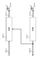
- the figure which shows the example of a structure in the case of performing the transmission method using a space-time block code The figure which shows the example of a structure in the case of performing the transmission method using a space-time block code
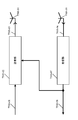
- the figure which shows the example of a structure in the case of performing the transmission method using a MIMO system The figure which shows the example of a structure in the case of performing the transmission method using a MIMO system
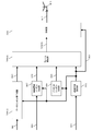
- the figure which shows the example of a structure in the case of performing the transmission method using a MIMO system The figure which shows the example of a structure in the case of performing the transmission method using a MIMO system
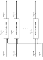
- the figure which shows the example of a structure in the case of performing the transmission method using a MIMO system The
- MIMO Multiple-Input Multiple-Output
- data reception quality is improved by modulating transmission data of one or more streams, and simultaneously transmitting each modulated signal from different antennas using the same frequency (common frequency). And / or increase the data communication speed (per unit time).
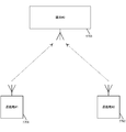
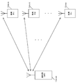
- FIG. 62 is a diagram for explaining the outline of the spatial multiplexing MIMO scheme.
- the MIMO scheme in the figure shows an example of the configuration of a transmission / reception apparatus when the number of transmission antennas is 2 (TX1, TX2), the number of reception antennas is 2 (RX1, RX2), and the number of transmission modulation signals (transmission streams) is 2.
- the transmission device has a signal generation unit and a wireless processing unit.
- the signal generation unit encodes data, performs MIMO precoding processing, uses the same frequency (common frequency), and transmits two transmission signals z1 (t) and z2 (t) that can be transmitted simultaneously. Generate.
- the radio processing unit multiplexes individual transmission signals in the frequency direction as necessary, that is, multicarrier (for example, OFDM (Orthogonal Frequency Division Multiplexing) method)), and the receiving apparatus performs transmission path distortion, A pilot signal for estimating frequency offset, phase distortion, etc. is inserted. However, other distortions or the like may be estimated for the pilot signal, and the pilot signal may be used by the receiving device for signal detection. Note that the usage form of the pilot signal receiving apparatus is not limited to this.
- the transmitting antenna transmits z1 (t) and z2 (t) using two antennas (TX1 and TX2).
- the receiving device includes a receiving antenna (RX1 and RX2), a radio processing unit, a channel fluctuation estimation unit, and a signal processing unit.
- the reception antenna (RX1) receives signals transmitted from the two transmission antennas (TX1 and TX2) of the transmission device.
- the channel fluctuation estimation unit estimates a channel fluctuation value using the pilot signal, and supplies the channel fluctuation estimation value to the signal processing unit.
- the signal processing unit restores data included in z1 (t) and z2 (t) based on the signals received by the two receiving antennas and the estimated channel value, and obtains this as one received data.
- the received data may be a hard decision value of “0” or “1”, or may be a soft decision value such as a log likelihood or a log likelihood ratio.
- turbo codes for example, Duo-Binary Turbo Codes
- LDPC Low-Density Parity-Check
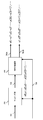
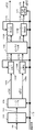
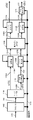
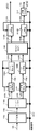
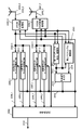
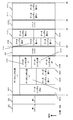
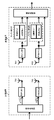
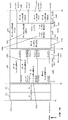
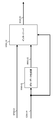
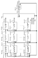
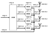
- FIG. 1 shows an example of the configuration of a transmission apparatus (for example, at a broadcasting station) in this embodiment.
- Data generation unit 102 receives transmission data 10801 and control signal 109 as input, and performs mapping based on error correction coding and modulation schemes based on information such as error correction coding information and modulation scheme information included in control signal 109. To output (orthogonal) baseband signal 103 for data transmission.
- Second preamble generation section 105 receives second preamble transmission data 104 and control signal 109 as input, and based on information such as second preamble error correction information and modulation scheme information contained in control signal 109, an error is generated. Mapping based on the correction coding and modulation scheme is performed, and the (orthogonal) baseband signal 106 of the second preamble is output.
- the control signal generation unit 108 receives the transmission data 107 for the first preamble and the transmission data 104 for the second preamble, and outputs information on the transmission method of each symbol as the control signal 109.
- the transmission method of each symbol includes, for example, an error correction code, a coding rate of the error correction code, a modulation method, a block length, a frame configuration, a selected transmission method including a transmission method that regularly switches a precoding matrix, and pilot symbol insertion.
- Method IFFT (Inverse Fourier Transform) (or inverse Fourier transform) / FFT (Fast Fourier Transform) (or Fourier transform) information, PAPR (Peak to Average Power Ratio) reduction method information, guard interval insertion method Information.
- the frame configuration unit 110 receives the (orthogonal) baseband signal 103 for data transmission, the (orthogonal) baseband signal 106 of the second preamble, and the control signal 109 as input, and based on the frame configuration information included in the control signal, the frequency Then, rearrangement in the time axis is performed, and (orthogonal) baseband signal 111_1 of stream 1 and (orthogonal) baseband signal 111_2 of stream 2 are output according to the frame configuration.
- the (orthogonal) baseband signal 111_1 of the stream 1 is a signal after mapping, that is, a baseband signal based on the modulation scheme to be used
- the (orthogonal) baseband signal 111_2 of the stream 2 is a signal after mapping, that is, This is a baseband signal based on the modulation method used.
- the signal processing unit 112 receives the baseband signal 111_1 of the stream 1, the baseband signal 111_2 of the stream 2, and the control signal 109, and the modulated signal 1 (113_1) after signal processing based on the transmission method included in the control signal 109 And the modulated signal 2 (113_2) after the signal processing is output.
- a MIMO transmission system using precoding and phase change herein referred to as a MIMO system
- a MISO Multiple-Input Single
- space-time block code frequency-space block code
- -Output transmission method
- SISO Single-Input Single-Output
- SIMO Single-Input Multiple-Output
- the transmission method shall be used.
- a modulated signal of one stream may be transmitted from a plurality of antennas.
- the operation of the signal processing unit 112 will be described in detail later.
- the MIMO transmission method may be a MIMO transmission method that does not change the phase.
- Pilot insertion section 114_1 receives modulated signal 1 (113_1) after signal processing and control signal 109 as input, and modulates signal 1 (113_1) after signal processing based on information relating to the pilot symbol insertion method included in control signal 109. A pilot symbol is inserted into, and modulated signal 115_1 after pilot symbol insertion is output.
- Pilot insertion section 114_2 receives modulated signal 2 (113_2) after signal processing and control signal 109 as input, and receives modulated signal 2 (113_2) after signal processing based on information on a pilot symbol insertion method included in control signal 109. A pilot symbol is inserted into, and modulated signal 115_2 after pilot symbol insertion is output.
- IFFT Inverse Fast Fourier Transform
- IFFT section 116_2 receives modulated signal 115_2 after pilot symbol insertion and control signal 109 as input, performs IFFT based on IFFT method information included in control signal 109, and outputs post-IFFT signal 117_2.
- the PAPR reduction unit 118_1 receives the signal 117_1 after IFFT and the control signal 109 as input, performs a process for PAPR reduction on the signal 117_1 after IFFT based on information on PAPR reduction included in the control signal 109, and after PAPR reduction
- the signal 119_1 is output.
- the PAPR reduction unit 118_2 receives the signal 117_2 after IFFT and the control signal 109 as input, performs a process for PAPR reduction on the signal 117_2 after IFFT based on information on PAPR reduction included in the control signal 109, and after PAPR reduction
- the signal 119_2 is output.
- the guard interval insertion unit 120_1 receives the signal 119_1 after PAPR reduction and the control signal 109 as inputs, and inserts a guard interval into the signal 119_1 after PAPR reduction based on the information on the guard interval insertion method included in the control signal 109.
- the signal 121_1 after the guard interval is inserted is output.
- the guard interval insertion unit 120_2 receives the signal 119_2 after the PAPR reduction and the control signal 109 as inputs, and inserts the guard interval into the signal 119_2 after the PAPR reduction based on the information regarding the method of inserting the guard interval included in the control signal 109.
- a signal 121_2 after insertion of the guard interval is output.
- the first preamble insertion unit 122 receives the signal 121_1 after the guard interval is inserted, the signal 121_2 after the guard interval is inserted, and the transmission data 107 for the first preamble, and receives the first preamble signal from the transmission data 107 for the first preamble.
- the first preamble is added to the signal 121_1 after the insertion of the guard interval, and the first preamble is added to the signal 123_1 after the addition of the first preamble and the signal 121_2 after the insertion of the guard interval.
- the signal 123_2 after adding the first preamble is output.
- the signal of the first preamble may be added to both the signal 123_1 after the addition of the first preamble and the signal 123_2 after the addition of the first preamble, or may be added to either one of them. Good. In the case where the signal is added to the other side, a zero signal is present as the baseband signal in the signal that is not added in the section where the added signal is added.
- the wireless processing unit 124_1 receives the signal 123_1 after the addition of the first preamble, performs processing such as frequency conversion and amplification, and outputs the transmission signal 125_1. Then, the transmission signal 125_1 is output as a radio wave from the antenna 126_1.
- the wireless processing unit 124_2 receives the signal 123_2 after the addition of the first preamble, performs processing such as frequency conversion and amplification, and outputs a transmission signal 125_2. Then, the transmission signal 125_2 is output as a radio wave from the antenna 126_2.
- the MIMO transmission method using precoding and phase change, space-time block code (Space Time Block codes) (or frequency-space block code (Space Frequency Block codes) ))
- MISO Multiple-Input Single-Output
- SISO Single-Input Single-Output
- SIMO Single-Input Single-Output
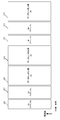
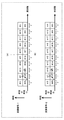
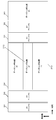
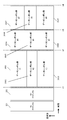
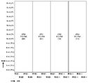
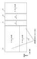
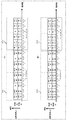
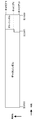
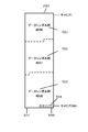
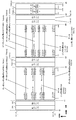
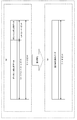
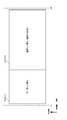
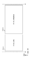
- FIG. 2 shows an example of the first frame configuration.
- the vertical axis represents frequency and the horizontal axis represents time. Since a transmission method using multicarriers such as the OFDM method is used, it is assumed that there are a plurality of carriers in the vertical axis frequency.
- 201 indicates a first preamble
- 202 indicates a second preamble
- 203 indicates a data symbol group # 1
- 204 indicates a data symbol group # 2
- 205 indicates a data symbol group # 3.
- a data symbol group may be assigned for each video and / or audio stream.
- a symbol for transmitting a first video and / or audio stream is a data symbol group # 1 (203)
- a symbol for transmitting a second video and / or audio stream is a data symbol group # 2 (204).
- Symbols for transmitting the third video and / or audio stream are data symbol group # 3 (205).
- PLP Physical Layer Layer Pipe
- DVB-T2 a second generation digital terrestrial television broadcasting system
- data symbol group # 1 (203) may be named PLP # 1
- data symbol group # 2 (204) may be named PLP # 2
- data symbol group # 3 (205) may be named PLP # 3.
- FIG. 2 data symbol group # 1 (203) may be named PLP # 1
- data symbol group # 2 (204) may be named PLP # 2
- data symbol group # 3 (205) may be named PLP # 3.
- This point is not limited to FIG. 2, and the same applies to FIG. 3, FIG. 4, FIG. 5, and FIG.
- symbols for frequency synchronization and time synchronization for example, PSK (Phase Shift) in which the signal point arrangement is known in the in-phase I-orthogonal Q plane for the transceiver. Keying) symbols, pilot symbols for the receiver to estimate channel fluctuations, for example, PSK (Phase Shift Keying) symbols for which the signal point arrangement is known in the in-phase I-orthogonal Q plane for the transceiver, each data Symbols for transmitting symbol group transmission method information (information identifying SISO, MISO, and MIMO) and information (for example, code length, coding rate) on error correction codes of each data symbol group are transmitted.
- PSK Phase Shift
- the characteristic point of FIG. 2 is that the data symbol group is transmitted in a time division manner.
- pilot symbols and symbols for transmitting control information may be inserted into the data symbol group.
- the data symbol group may be a symbol group based on a MIMO (transmission) method and a MISO (transmission) method.
- the data symbol group may be a symbol group of a SISO (SIMO) system.
- a plurality of streams (s1 and s2 described later) are transmitted at the same time and the same (common) frequency.
- a plurality of modulated signals are transmitted from a plurality of (different) antennas at the same time and the same (common) frequency. This point is not limited to FIG. 2, and the same applies to FIG. 3, FIG. 4, FIG. 5, and FIG.
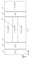
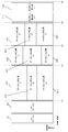
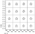
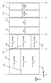
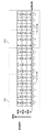
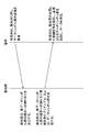
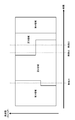
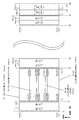
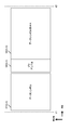
- FIG. 3 shows an example of the second frame configuration.
- the vertical axis represents frequency and the horizontal axis represents time. Since a transmission method using multicarriers such as the OFDM method is used, it is assumed that there are a plurality of carriers in the vertical axis frequency. 3 that are the same as those in FIG. 2 are assigned the same reference numerals and operate in the same manner as in FIG.
- a characteristic point in FIG. 3 is that the first preamble 301 and the second preamble 302 are inserted between the data symbol group # 2 (204) and the data symbol group # 3 (205) (in time). . That is, when a symbol group formed by “first preamble, second preamble, data symbol group” is named a group, the first preamble, the second preamble, the data symbol group # 1, and the data symbol group # 2 are included. 1 group and the second group including the first preamble, the second preamble, and the data symbol group # 3, and the configuration of the data symbol group included in the first group and the data symbol group included in the second group is Will be different.
- the video and / or audio transmitted in the data symbol group # 1 and the video and / or audio transmitted in the data symbol group # 2 have different video and / or audio encoding compression rates.
- the same “video and / or audio” may be used.
- the receiving apparatus increases the desired “video and / or audio” by a simple method of selecting “demodulate data symbol group # 1 or demodulate data symbol group # 2”. Since it can be obtained with quality and the preamble can be shared at this time, there is an advantage that the transmission efficiency of control information can be increased.
- the video and / or audio transmitted in the data symbol group # 1 may be different from the video and / or audio transmitted in the data symbol # 2 without following this.
- the transmission method for transmitting data symbol group # 1 is the same as the transmission method for transmitting data symbol group # 2, and the transmission method for transmitting data symbol group # 3 and data symbol group # 1 are the same. Can be easily made different from the transmission method for transmitting (the transmission method for transmitting data symbol group # 2).
- pilot symbols are inserted in the data symbol group.
- the pilot symbol insertion method differs depending on the transmission method. Since the number of modulated signals to be transmitted may differ, it is possible to prevent a decrease in transmission efficiency due to pilot symbol insertion by collecting data symbol groups for each transmission method.
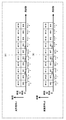
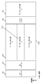
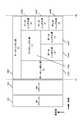
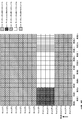
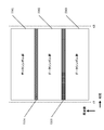
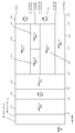
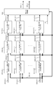
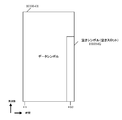
- FIG. 4 shows an example of the third frame configuration.
- the vertical axis represents frequency and the horizontal axis represents time. Since a transmission scheme using multicarriers such as the OFDM scheme is used, it is assumed that there are a plurality of carriers in the vertical axis frequency. 4 that operate in the same manner as in FIG. 2 are given the same reference numerals and operate in the same manner as in FIG.
- a characteristic point in FIG. 4 is that data symbol group # 1 and data symbol group # 2 are frequency-divided, and in addition, “data symbol group # 1 (401_1) and data symbol group # 2 (402)”. “Data symbol group # 3 (403)” is time-divided. That is, the data symbol group is transmitted by using both frequency division and time division.
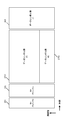
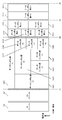
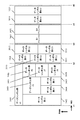
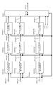
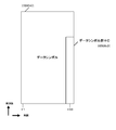
- FIG. 5 shows an example of the fourth frame configuration.
- the vertical axis represents frequency and the horizontal axis represents time. Since a transmission scheme using multicarriers such as the OFDM scheme is used, it is assumed that there are a plurality of carriers in the vertical axis frequency. 5 that operate in the same manner as in FIGS. 2 and 4 are denoted by the same reference numerals, and operate in the same manner as in FIGS.
- the data symbol group # 1 and the data symbol group # 2 are frequency-divided.
- “data symbol group # 1 (401_1) and data symbol group # 2 (402) ”and“ data symbol group # 3 (403) ” are time-divided. That is, the data symbol group is transmitted by using both frequency division and time division.
- the first preamble 301 and the second preamble are between the “data symbol group # 1 (401_1, 401_2) and data symbol # 2 (402)” and the data symbol group # 3 (403) (in time).
- the preamble 302 is inserted. That is, when a symbol group formed by “first preamble, second preamble, data symbol group” is named a group, the first preamble, the second preamble, the data symbol group # 1, and the data symbol group # 2 are included. 1 group and a second group including a first preamble, a second preamble, and a data symbol group # 3, and a configuration of a data symbol group included in the first group and a data symbol group included in the second group Will be different.
- the video and / or audio transmitted in the data symbol group # 1 and the video and / or audio transmitted in the data symbol group # 2 have different video and / or audio encoding compression rates.
- the same “video and / or audio” may be used.
- the receiving apparatus increases the desired “video and / or audio” by a simple method of selecting “demodulate data symbol group # 1 or demodulate data symbol group # 2”. Since it can be obtained with quality and the preamble can be shared at this time, there is an advantage that the transmission efficiency of control information can be increased.
- the video and / or audio transmitted in the data symbol group # 1 may be different from the video and / or audio transmitted in the data symbol # 2 without following this.
- the transmission method for transmitting data symbol group # 1 and the transmission method for transmitting data symbol group # 2 are the same, and the transmission method for transmitting data symbol group # 3 and data symbol group # 1 are It becomes easy to make the transmission method for transmission (transmission method for transmitting data symbol group # 2) different.
- pilot symbols are inserted in the data symbol group.
- the pilot symbol insertion method differs depending on the transmission method. Since the number of modulated signals to be transmitted may differ, it is possible to prevent a decrease in transmission efficiency due to pilot symbol insertion by collecting data symbol groups for each transmission method.
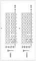
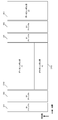
- FIG. 6 shows an example of the fifth frame configuration.
- the vertical axis represents frequency and the horizontal axis represents time. Since a transmission scheme using multicarriers such as the OFDM scheme is used, it is assumed that there are a plurality of carriers in the vertical axis frequency. 6 that operate in the same manner as in FIGS. 2 and 4 are denoted by the same reference numerals, and operate in the same manner as in FIGS.
- FIG. 6 a characteristic point is that, similarly to FIGS. 4 and 5, the data symbol group # 1 and the data symbol group # 2 are frequency-divided, and in addition, “data symbol group # 1 (401_1) and data symbol Group # 2 (402) "and” Data symbol group # 3 (403) "are time-divided. That is, the data symbol group is transmitted by using both frequency division and time division.
- pilot symbols are inserted between (in terms of time) “data symbol group # 1 (401_1, 401_2) and data symbol # 2 (402)” and data symbol group # 3 (403). Is a point.
- the video and / or audio transmitted in the data symbol group # 1 and the video and / or audio transmitted in the data symbol group # 2 have different video and / or audio encoding compression rates.
- the same “video and / or audio” may be used.
- the receiving apparatus increases the desired “video and / or audio” by a simple method of selecting “demodulate data symbol group # 1 or demodulate data symbol group # 2”. Since it can be obtained with quality and the preamble can be shared at this time, there is an advantage that the transmission efficiency of control information can be increased.
- the video and / or audio transmitted in the data symbol group # 1 may be different from the video and / or audio transmitted in the data symbol # 2 without following this.
- the transmission method for transmitting data symbol group # 1 and the transmission method for transmitting data symbol group # 2 are the same, and the transmission method for transmitting data symbol group # 3 and data symbol group # 1 are It becomes easy to make the transmission method for transmission (transmission method for transmitting data symbol group # 2) different.
- pilot symbols are inserted in the data symbol group.
- the pilot symbol insertion method differs depending on the transmission method. Since the number of modulated signals to be transmitted may differ, it is possible to prevent a decrease in transmission efficiency due to pilot symbol insertion by collecting data symbol groups for each transmission method.
- a pilot symbol is inserted into each modulation signal transmitted from each transmission antenna.
- the receiving apparatus can perform channel estimation for detecting and demodulating each data symbol group with high accuracy.
- the receiving apparatus must adjust the gain of the reception signal suitable for the transmission method.
- the pilot symbol 601 can easily adjust the gain. Can be obtained.
- video and / or audio transmitted in the data symbol group # 1 and video and / or audio transmitted in the data symbol group # 2 are codes of video and / or audio.
- the same “video and / or audio” may be used.
- the receiving apparatus increases the desired “video and / or audio” by a simple method of selecting “demodulate data symbol group # 1 or demodulate data symbol group # 2”. Since it can be obtained with quality and the preamble can be shared at this time, there is an advantage that the transmission efficiency of control information can be increased.
- the video and / or audio transmitted in the data symbol group # 1 may be different from the video and / or audio transmitted in the data symbol # 2 without following this.
- a time-division data symbol group is arranged after a frequency-division data symbol group.
- a data symbol group that is frequency-divided later may be arranged.
- the first preamble and the second preamble are inserted between the time-division data symbol group and the frequency-division data symbol group.
- other symbols may be inserted.
- pilot symbols are inserted between the time-divided data symbol group and the frequency-divided data symbol group.
- other symbols may be inserted.
- each of the frame configurations of FIGS. 2 to 6 has advantages. Therefore, the transmission apparatus selects one of the frame configurations in FIG. 2 to FIG. 6 according to the compression rate and type of data (stream), the combination method of transmission methods, and the service method desired to be provided to the terminal, and controls information, pilot Symbols such as symbols and data symbols are transmitted.
- the transmission apparatus may include “information on the frame configuration” for transmitting the information on the frame configuration to the reception device (terminal) in the first preamble or the second preamble. .
- the receiving device can know the outline of the frame configuration of the modulated signal transmitted by the transmitting device from the “information on the frame configuration”.
- the data symbol group is a symbol of any one of the SISO (or SIMO) system, the MISO system, and the MIMO system.
- SISO or SIMO
- MISO magnetic resonance
- MIMO multiplexing
- MISO transmission
- space-time block code frequency-space block code
- Mapping section 702 receives data signal (data after error correction coding) 701 and control signal 706 as input, performs mapping based on information related to the modulation method included in control signal 706, and outputs mapped signal 703. Output. For example, it is assumed that the mapped signal 703 is arranged in the order of s0, s1, s2, s3,..., S (2i), s (2i + 1),. And).
- a MISO (Multiple Input Multiple Output) processing unit 704 receives the mapped signal 703 and the control signal 706 as input, and when the control signal 706 instructs transmission using the MISO method, the signals 705A and 705B after the MISO processing. Is output.
- the signal 705A after MISO processing is s0, s1, s2, s3,..., S (2i), s (2i + 1),...
- the signal 705B after MISO processing is ⁇ s1 * , s0 * , ⁇ s3 * , s2 * ..., ⁇ s (2i + 1) * , s (2i) * ,.
- * means a complex conjugate (for example, s0 * is a complex conjugate of s0).
- signals 705A and 705B after MISO processing correspond to modulated signal 1 (113_1) after signal processing and modulated signal 2 (113_2) after signal processing in FIG. 1, respectively.
- the space-time block code method is not limited to the above description.
- the modulated signal 1 (113_1) after the signal processing is subjected to predetermined processing and transmitted as a radio wave from the antenna 126_1.
- the modulated signal 2 (113_2) after the signal processing is subjected to predetermined processing and transmitted as a radio wave from the antenna 126_2.
- FIG. 8 shows a configuration when a transmission method using space-time block codes (Space-Time Block Codes) different from FIG. 7 is performed.
- Mapping section 702 receives data signal (data after error correction coding) 701 and control signal 706 as input, performs mapping based on information related to the modulation method included in control signal 706, and outputs mapped signal 703. Output. For example, it is assumed that the mapped signal 703 is arranged in the order of s0, s1, s2, s3,..., S (2i), s (2i + 1),. And).
- a MISO (Multiple Input Multiple Output) processing unit 704 receives the mapped signal 703 and the control signal 706 as input, and when the control signal 706 instructs transmission using the MISO method, the signals 705A and 705B after the MISO processing. Is output.
- the signal 705A after MISO processing is s0, -s1 * , s2, -s3 * , ..., s (2i), -s (2i + 1) * , ...
- the signal 705B after MISO processing is s1 , S0 * , s3, s2 * ..., S (2i + 1), s (2i) * ,.
- “ * ” Means a complex conjugate.
- s0 * is a complex conjugate of s0.
- signals 705A and 705B after MISO processing correspond to modulated signal 1 (113_1) after signal processing and modulated signal 2 (113_2) after signal processing in FIG. 1, respectively.
- the space-time block code method is not limited to the above description.
- the modulated signal 1 (113_1) after the signal processing is subjected to predetermined processing and transmitted as a radio wave from the antenna 126_1.
- the modulated signal 2 (113_2) after the signal processing is subjected to predetermined processing and transmitted as a radio wave from the antenna 126_2.
- the method of transmitting a plurality of streams from a plurality of antennas is not limited to this, and the present embodiment can be implemented even with other methods.
- the encoding unit 1102 in FIG. 9 receives the information 1101 and the control signal 1112 as input, performs encoding based on the information of the encoding rate and code length (block length) included in the control signal 1112, and performs encoding. Data 1103 is output.
- the mapping unit 1104 receives the encoded data 1103 and the control signal 1112 as inputs. Then, it is assumed that the control signal 1112 designates transmission of two streams as the transmission method. In addition, it is assumed that the control signal 1112 designates the modulation method ⁇ and the modulation method ⁇ as the modulation methods of the two streams.
- the modulation method ⁇ is a modulation method that modulates x-bit data
- the modulation method ⁇ is a modulation method that modulates y-bit data.
- 16QAM (16QQuadrature Amplitude Modulation) is a modulation method that modulates 4-bit data
- 64QAM 64 Quadrature Amplitude Modulation
- the mapping unit 1104 modulates the x-bit data of the x + y-bit data with the modulation scheme ⁇ , generates and outputs a baseband signal s 1 (t) 1105A, and also outputs the remaining y-bit data
- the data of the data is modulated by the modulation method ⁇ and the baseband signal s 2 (t) 1105B is output (in FIG. 9, only one mapping unit is provided.
- the mapping unit for generating 1 (t) and the mapping unit for generating s 2 (t) may exist separately, and at this time, the encoded data 1103 includes s 1 (t). And a mapping unit for generating s 2 (t).
- s 1 (t) and s 2 (t) are expressed by complex numbers (however, they may be complex numbers or real numbers), and t is time.
- s 1 and s 2 are functions of the frequency f such as s 1 (f) and s 2 (f), Alternatively, it can be considered as a function of time t and frequency f, such as s 1 (t, f) and s 2 (t, f).
- the baseband signal, precoding matrix, phase change, and the like are described as functions of time t, but may be considered as functions of frequency f, functions of time t, and frequency f.
- symbols and baseband signals may be generated and arranged in the time axis direction, or may be generated and arranged in the frequency axis direction. Further, symbols and baseband signals may be generated and arranged in the time axis direction and the frequency axis direction.
- the power changing unit 1106A receives the baseband signal s 1 (t) 1105A and the control signal 1112 as input, sets a real number P 1 based on the control signal 1112, and sets P 1 ⁇ s 1 ( t) is output as the signal 1107A after the power change. Note that although P 1 is a real number, it may be a complex number.
- power changing section 1106B receives baseband signal s 2 (t) 1105B and control signal 512, sets real number P 2, and sets P 2 ⁇ s 2 (t). It is output as a signal 1107B after power change.
- P 2 a real number, it may be a complex number.
- the weighting synthesis unit 1108 receives the signal 1107A after power change, the signal 1107B after power change, and the control signal 1112, and sets a precoding matrix F (or F (i)) based on the control signal 1112. When the slot number (symbol number) is i, the weighting synthesis unit 1108 performs the following calculation.
- a (i), b (i), c (i), and d (i) can be expressed by complex numbers (may be real numbers), and a (i), b (i), and c (i ), D (i), three or more must not be 0 (zero).
- the precoding matrix may be a function of i or may not be a function of i. When the precoding matrix is a function of i, the precoding matrix is switched by the slot number (symbol number).
- the weighting / combining unit 1108 outputs u 1 (i) in Expression (1) as a signal 1109A after weighted composition, and outputs u 2 (i) in Expression (1) as a signal 1109B after weighted composition.
- the power changing unit 1110A receives the weighted combined signal 1109A (u 1 (i)) and the control signal 512, sets a real number Q 1 based on the control signal 1112, and Q 1 ⁇ u 1 (t) Is output as a signal 1111A (z 1 (i)) after the power change (Q 1 is a real number, but it may be a complex number).
- the power changing unit 1110B receives the weighted combined signal 1109B (u 2 (i)) and the control signal 1112 as input, sets a real number Q 2 based on the control signal 512, and sets Q 2 ⁇ u 2.
- (T) is output as a signal 1111B (z 2 (i)) after power change (note that Q 2 is a real number, but may be a complex number).
- the phase changing unit 1161 receives u 2 (i) in the equation (1) as a signal 1109B after the weighted synthesis and the control signal 1112 and inputs u 2 (i) in the equation (1) based on the control signal 1112.
- the phase of the later signal 1109B is changed. Therefore, the signal after changing the phase of the signal 1109B after the weighted synthesis of u 2 (i) in Equation (1) is expressed as e j ⁇ (i) ⁇ u 2 (i), and e j ⁇ (i) ⁇ u 2 (i) is output as the signal 1162 after the phase change, and the phase change unit 1161 outputs (j is an imaginary unit).
- the phase value to be changed is a characteristic part that is a function of i, such as ⁇ (i).
- the power change parts 1110A and 1110B of FIG. 10 perform the power change of an input signal, respectively. Therefore, the outputs z 1 (i) and z 2 (i) of the power changing units 1110A and 1110B in FIG. 10 are expressed by the following equations.
- FIG. 11 is a configuration different from FIG. The difference between FIG. 10 and FIG. 11 is that the order of the power changing unit and the phase changing unit is switched. The function of changing power or changing phase does not change.
- z 1 (i) and z 2 (i) are expressed as follows.
- phase value ⁇ (i) to be changed in the equations (3) and (4) is set so that, for example, ⁇ (i + 1) ⁇ (i) is a fixed value, the direct wave is dominant. In the environment, the reception device is likely to obtain good data reception quality.
- the method of giving the phase value ⁇ (i) to be changed is not limited to this example.
- z 1 (i) and z 2 (i) are expressed as follows. .
- z 1 (i) and z 2 (i) are expressed as follows. .
- a power changing unit 1106A (power adjusting unit 1106A), a power changing unit 1106B (power adjusting unit 1106B), a power changing unit 1110A (power adjusting unit 1110A), and a power changing unit 1110B (power adjusting unit 1110B).
- z 1 (i) and z 2 (i) are expressed as follows:
- z 1 (i) and z 2 (i) are as follows: Appears.
- z 1 (i) and z 2 (i) are as follows: Appears.
- z 1 (i) and z 2 (i) are expressed as follows:
- a characteristic point is that a phase changing unit 1151 is inserted.
- the phase changing unit 1151 receives the baseband signal s 2 (i) 1105B and the control signal 1112 as input, and changes the phase of the baseband signal s 2 (i) 1105B based on the control signal 1112. At this time, the value of the phase change is set to e j ⁇ (i) (j is an imaginary unit). Note that the phase value to be changed is a characteristic part that is a function of i, such as ⁇ (i).
- equation (11) z 1 (i) and z 1 of the formula (12) (i) are equal, equation (11) z 2 a (i) and Formula (12) z 2 a (i) Are equal.
- FIG. 13 shows another configuration capable of realizing the same processing as in FIG.
- components that operate in the same manner as in FIGS. 9 to 12 are given the same reference numerals, and descriptions thereof are omitted.
- 12 differs from FIG. 13 in that the order of the power changing unit 1110B and the phase changing unit 1161 is changed in FIG. The function of changing power or changing phase does not change.
- z 1 (i) in formula (11) is equal to z 1 in formula (12) (i)
- z 1 (i) in formula (13) is equal to z 1 (i) in formula (14)
- z 2 (i) of formula (11) z 2 (i) and the z 2 of z 2 (i) and formula (13) in equation (12) (i) and formula (14) are equal.
- a characteristic point is that a phase changing unit 1181 and a phase changing unit 1151 are inserted.
- the phase changing unit 1151 receives the baseband signal s 2 (i) 1105B and the control signal 1112 as input, and changes the phase of the baseband signal s 2 (i) 1105B based on the control signal 1112. At this time, the value of the phase change is set to e j ⁇ (i) (j is an imaginary unit). Note that the phase value to be changed is a characteristic part that is a function of i, such as ⁇ (i).
- the phase changing unit 1181 receives the baseband signal s 1 (i) 1105A and the control signal 1112 as input, and changes the phase of the baseband signal s 1 (i) 1105A based on the control signal 1112. At this time, the phase change value is set to e j ⁇ (i) (j is an imaginary unit).
- the phase value to be changed is a characteristic part that is a function of i, such as ⁇ (i).
- a configuration different from that in FIG. 14 is a configuration in which the order of the power changing unit 1106B and the phase changing unit 1151 is changed, and the order of the power changing unit 1106A and the phase changing unit 1181 is changed. is there.
- the function of changing power or changing phase does not change.
- z 1 (i) and z 2 (i) are expressed as follows.
- equation (15) z 1 (i) and z 1 of the formula (16) (i) z 2 of equal, equation (15) (i) and Formula (16) z 2 a (i) are equal.
- FIG. 15 shows another configuration capable of realizing the same processing as in FIG. 15 that operate in the same manner as in FIGS. 9 to 14 are denoted by the same reference numerals and description thereof is omitted.
- 14 and FIG. 15 is different from FIG. 14 in that the order of the power changing unit 1110B and the phase changing unit 1161 is changed as shown in FIG. 15 (the function itself for changing the power and changing the phase is Unchanged).
- z 1 (i) in equation (15) is equal to z 1 in equation (16)
- z 1 (i) in equation (17) is equal to z 1 (i) in equation (18)
- z 2 (i) of the z 2 (i) and z 2 (i) and formula z 2 (i) and formula (17) in equation (16) (18) of the formula (15) are equal.
- a characteristic point is that a phase change unit 1181, a phase change unit 1151, a phase change unit 1110A, and a phase change unit 1110B are inserted.
- the phase changing unit 1151 receives the baseband signal s 2 (i) 1105B and the control signal 1112 as input, and changes the phase of the baseband signal s 2 (i) 1105B based on the control signal 1112. At this time, the value of the phase change is set to e j ⁇ (i) (j is an imaginary unit). Note that the phase value to be changed is a characteristic part that is a function of i, such as ⁇ (i).
- the phase changing unit 1181 receives the baseband signal s 1 (i) 1105A and the control signal 1112 as input, and changes the phase of the baseband signal s 1 (i) 1105A based on the control signal 1112. At this time, the phase change value is set to e j ⁇ (i) (j is an imaginary unit).
- the phase value to be changed is a characteristic part that is a function of i, such as ⁇ (i).
- the phase changing unit 1161 changes the phase of the input signal. Let the phase change value at that time be ⁇ (i). Similarly, the phase changing unit 1191 changes the phase of the input signal. Let the phase change value at that time be ⁇ (i).
- a configuration different from that in FIG. 16 is a configuration in which the order of the power changing unit 1106B and the phase changing unit 1151 is changed and the order of the power changing unit 1106A and the phase changing unit 1181 is changed. is there.
- the function of changing power or changing phase does not change.
- z 1 (i) and z 2 (i) are expressed as follows.
- equation (19) z 1 z 1 of (i) and Formula (20) (i) are equal, equation (19) z 2 (i) and Formula (20) z 2 a (i) are equal.
- FIG. 17 shows another configuration capable of realizing the same processing as in FIG.
- the same reference numerals are given to components that operate in the same manner as in FIGS. 16 and FIG. 17 are different from FIG. 14 in that the order of the power changing unit 1110B and the phase changing unit 1161 is changed, and the order of the power changing unit 1110A and the phase changing unit 1191 is changed. It becomes.
- the function of changing power or changing phase does not change.
- a configuration different from that in FIG. 17 is a configuration in which the order of the power changing unit 1106B and the phase changing unit 1151 is changed and the order of the power changing unit 1106A and the phase changing unit 1181 is changed. is there.
- the function of changing power or changing phase does not change.
- z 1 (i) and z 2 (i) are expressed as follows.
- equation (19) z 1 of (i) and z 1 (i) of the formula z 1 (i) formula (20) (21) z 1 of (i) and Formula (22) are equal
- z 2 of the formula (19) z 2 a (i) and z 2 of z 2 (i) and formula (21) in equation (20) (i) and formula (22) (i) are equal.
- the matrix F for weighted synthesis is shown.
- each embodiment of the present specification can be used even if a precoding matrix F (or F (i)) as described below is used. Can be implemented.
- ⁇ may be a real number. It may be an imaginary number, and ⁇ may be a real number or an imaginary number. However, ⁇ is not 0 (zero). ⁇ is not 0 (zero). Or
- ⁇ may be a real number or an imaginary number. However, ⁇ is not 0 (zero).
- ⁇ 11 (i), ⁇ 21 (i), and ⁇ (i) are functions of i
- ⁇ is a fixed value
- ⁇ may be a real number or an imaginary number
- ⁇ may be a real number or an imaginary number.
- ⁇ is not 0 (zero).
- ⁇ is not 0 (zero).
- i is either time or frequency, or both time and frequency.
- ⁇ (i) is a function of i, and ⁇ may be a real number or an imaginary number. However, ⁇ is not 0 (zero). i is either time and frequency or both time and frequency.
- a method may be used in which the modulated signal is generated by performing precoding without performing the phase change described above, and the transmitting apparatus transmits the modulated signal.
- the modulated signal is generated by performing precoding without performing the phase change described above, and the transmitting apparatus transmits the modulated signal.
- FIG 9 (i), or, z 1 (i) of formula (56) or, z 1 (i) of formula (57), or, the formula (58) z 1 (i), or, z 1 (i) of formula (59) or, z 1 (i) of formula (60) corresponds to the modulated signal 1 (113_1) after the signal processing of FIG. 1, z 2 obtained in FIG. 17.
- FIG 9 (i), or, z 2 (i) of formula (56) or, z 2 (i) of formula (57) or, z 2 of the formula (58) (i), or, z 2 (i) of formula (59) or, z 2 (i) of formula (60) corresponds to the modulated signal 2 (113_2)
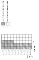
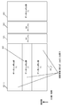
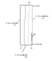
- FIG. 18 shows the arrangement method of z 1 (i)
- (B) in FIG. 18 shows the arrangement method of z 2 (i).
- the vertical axis represents time
- the horizontal axis represents frequency.
- z 2 (0), z 2 (1), z 2 (2), z 2 (3) corresponding to i 0, 1, 2, 3,. ), ... z 2 (0) is placed at carrier 0, time 1, z 2 (1) is placed at carrier 1, time 1, z 2 (2) is placed at carrier 2, time 1, ... z 2 (10) is placed at carrier 0, time 2, z 2 (11) is placed at carrier 1, time 2, z 2 (12) is placed at carrier 2, time 2, ... And
- FIG. 18 shows an example in which the generated z 1 (i) and z 2 (i) are preferentially arranged in the frequency axis direction.
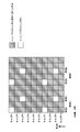
- FIG. 19 shows the arrangement method of z 1 (i)
- (B) in FIG. 19 shows the arrangement method of z 2 (i).
- the vertical axis represents time
- the horizontal axis represents frequency.
- z 2 (0), z 2 (1), z 2 (2), z 2 (3) corresponding to i 0, 1, 2, 3,. ), ... z 2 (0) is placed at carrier 0, time 1, z 2 (1) is placed at carrier 1, time 2, z 2 (2) is placed at carrier 2, time 1, ... z 2 (10) is placed at carrier 2, time 2, z 2 (11) is placed at carrier 7, time 1, z 2 (12) is placed at carrier 8, time 2, ... And
- FIG. 19 shows an example in which the generated z 1 (i) and z 2 (i) are randomly arranged in the frequency and time axis directions.
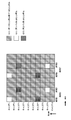
- FIG. 20 shows the arrangement method of z 1 (i)
- (B) in FIG. 20 shows the arrangement method of z 2 (i).
- the vertical axis represents time
- the horizontal axis represents frequency.
- z 2 (0), z 2 (1), z 2 (2), z 2 (3) corresponding to i 0, 1, 2, 3,. ), ... z 2 (0) is placed at carrier 0, time 1, z 2 (1) is placed at carrier 2, time 1, z 2 (2) is placed at carrier 4, time 1, ... z 2 (10) is placed at carrier 0, time 2, z 2 (11) is placed at carrier 2, time 2, z 2 (12) is placed at carrier 4, time 2, ... And
- FIG. 20 shows an example in which the generated z 1 (i) and z 2 (i) are preferentially arranged in the frequency axis direction.
- FIG. 21 shows the arrangement method of z 1 (i)
- (B) in FIG. 21 shows the arrangement method of z 2 (i).
- the vertical axis represents time
- the horizontal axis represents frequency.
- z 2 (0), z 2 (1), z 2 (2), z 2 (3) corresponding to i 0, 1, 2, 3,. ), ... z 2 (0) is placed at carrier 0, time 1, z 2 (1) is placed at carrier 1, time 1, z 2 (2) is placed at carrier 0, time 2, ... z 2 (10) is placed at carrier 2, time 2, z 2 (11) is placed at carrier 3, time 2, z 2 (12) is placed at carrier 2, time 3, ... And
- FIG. 21 shows an example of arranging the generated z 1 (i) and z 2 (i) in the time and frequency axis directions.
- FIG. 22 shows the arrangement method of z 1 (i)
- (B) in FIG. 22 shows the arrangement method of z 2 (i).
- the vertical axis represents time
- the horizontal axis represents frequency.
- z 2 (0), z 2 (1), z 2 (2), z 2 (3) corresponding to i 0, 1, 2, 3,. ), ... z 2 (0) is placed at carrier 0, time 1, z 2 (1) is placed at carrier 0, time 2, z 2 (2) is placed at carrier 0, time 3, ... z 2 (10) is placed at carrier 2, time 3, z 2 (11) is placed at carrier 2, time 4, z 2 (12) is placed at carrier 3, time 1, ... And
- FIG. 22 shows an example in which the generated z 1 (i) and z 2 (i) are preferentially arranged in the time axis direction.
- the transmitting apparatus may arrange symbols by any method of FIGS. 18 to 22 or other symbol arrangement methods. 18 to 22 are only examples of symbol arrangement.
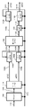
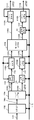
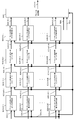
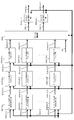
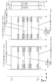
- FIG. 23 is a configuration example of a receiving device (terminal) that receives the modulated signal transmitted by the transmitting device of FIG.
- an OFDM scheme-related processing unit 2303_X receives the received signal 2302_X received by the antenna 2301_X, performs reception-side signal processing for the OFDM scheme, and outputs a signal 2304_X after the signal processing.
- the OFDM scheme-related processing unit 2303_Y receives the received signal 2302_Y received by the antenna 2301_Y, performs reception-side signal processing for the OFDM scheme, and outputs a signal 2304_Y after signal processing.
- the first preamble detection / decoding unit 2311 receives the signal processed signals 2304_X and 2304_Y and detects the first preamble, thereby performing signal detection and time-frequency synchronization, and simultaneously performs demodulation and error correction decoding. As a result, the control information included in the first preamble is obtained, and the first preamble control information 2312 is output.
- Second preamble demodulation section 2313 receives signals 2304_X and 2304_Y after signal processing and first preamble control information 2312 as input, performs signal processing based on the first preamble control information 2312, and demodulates (including error correction decoding). ) And the second preamble control information 2314 is output.
- the control information generation unit 2315 receives the first preamble control information 2312 and the second preamble control information 2314, and outputs control information (related to the reception operation) as a spring and a control signal 2316.
- the control signal 2316 is input to each unit as shown in FIG.
- Channel fluctuation estimation section 2305_1 of the modulated signal z 1 the signal after the signal processing 2304_X, control signal 2316 as input, transmitting apparatus after the signal processing channel fluctuation between the receiving antenna 2301_X antenna that has transmitted the modulated signal z 1 Estimation is performed using a pilot symbol included in the signal 2304_X, and a channel estimation signal 2306_1 is output.
- Channel fluctuation estimation section 2305_2 of the modulated signal z 2 the signal after the signal processing 2304_X, control signal 2316 as input, transmitting apparatus after the signal processing channel fluctuation between the receiving antenna 2301_X antenna that has transmitted the modulated signal z 2 Estimation is performed using pilot symbols included in the signal 2304_X, and a channel estimation signal 2306_2 is output.
- Channel fluctuation estimation section 2307_1 of the modulated signal z 1 the signal after the signal processing 2304_Y, control signal 2316 as input, transmitting apparatus after the signal processing channel fluctuation between the receiving antenna 2301_Y antenna that has transmitted the modulated signal z 1 Estimation is performed using pilot symbols included in the signal 2304_Y, and a channel estimation signal 2308_1 is output.
- Channel fluctuation estimation section 2307_2 of the modulated signal z 2 the signal after the signal processing 2304_Y, control signal 2316 as input, transmitting apparatus after the signal processing channel fluctuation between the receiving antenna 2301_Y antenna that has transmitted the modulated signal z 2 Estimation is performed using pilot symbols included in the signal 2304_Y, and a channel estimation signal 2308_2 is output.
- the signal processing unit 2309 receives the signals 2306_1, 2306_2, 2308_1, 2308_2, 2304_X, 2304_Y and the control signal 2316, and includes the transmission method, modulation method, error correction coding method, error included in the control signal 2316, and the like. Based on information such as the coding rate of the correction coding and the block size of the error correction code, demodulation and decoding are performed, and reception data 2310 is output. At this time, detection (demodulation) and decoding are performed based on the transmission method described above.
- the receiving apparatus extracts necessary symbols from the control signal 2316, performs demodulation (including signal separation and signal detection), and performs error correction decoding. Further, the configuration of the receiving device is not limited to this.
- each frame configuration of FIGS. 2 to 6 has advantages as described above. Therefore, the transmission apparatus may use the frame configurations of FIGS. 2 to 6 alone, and at that time, the effects described in the above description can be obtained.
- any of the frame configurations of FIGS. 2 to 6 is installed.
- the frame configuration may be switched such that it is sometimes set and periodically reviewed, or the frame configuration shown in FIGS. 2 to 6 may be selected for each frame transmission. Any method for selecting a frame configuration may be used.
- the preamble is composed of the first preamble and the second preamble, but the structure of the preamble is not limited to this, and is composed only of the first preamble (first preamble group). Alternatively, it may be composed of two or more preambles (preamble group). It should be noted that the preamble configuration is the same when the frame configuration of another embodiment is shown.
- the data symbol group is shown in the frame configurations of FIGS. 2 to 6, but other symbols such as pilot symbols and null symbols (the in-phase component of the symbol is 0 (zero, the quadrature component is 0 (zero)). ), A control information symbol or the like may be inserted. This also applies to the case where the frame configuration of another embodiment is shown.
- pilot symbol and a null symbol the in-phase component of the symbol is 0 (zero, the orthogonal component is 0 (zero)
- control information symbol a data symbol, and the like
- data symbol a data symbol, and the like
- the transmission apparatus may transmit “information about the frame configuration” for transmitting the information about the frame configuration to the reception apparatus (terminal) in the first preamble or the second preamble. .
- the receiving device can know the outline of the frame configuration of the modulated signal transmitted by the transmitting device from the “information on the frame configuration”.
- the transmission apparatus includes control information relating to the transmission method of each data symbol group, control information relating to the modulation scheme (or set of modulation schemes) of each data symbol group, and error correction codes used in each data symbol group.
- control information related to the code length (block length) and the coding rate is transmitted, and information related to a method for configuring a data symbol group in each frame configuration is also transmitted.
- MIMO scheme # 1 and MIMO scheme # 2 are different schemes, and are any of the above-described MIMO schemes. Also, here, MIMO scheme # 1 and MIMO scheme # 2 are handled, but the MIMO scheme that can be selected by the transmission apparatus may be one type or two or more types.
- the transmission apparatus sets the data symbol modulation scheme to QPSK.
- SISO single stream transmission
- the transmission apparatus sets the data symbol modulation scheme to 16QAM.
- the transmission apparatus sets the data symbol modulation scheme to 64QAM.
- the transmission apparatus sets the data symbol modulation scheme to 256QAM.
- MIMO scheme # 1 MIMO scheme # 2
- MIMO scheme # 2 MIMO scheme # 2
- the transmitting apparatus sets the data symbol modulation scheme to QPSK for stream 1 and 16QAM for stream 2.
- the transmission apparatus sets the data symbol modulation scheme to 16QAM for stream 1 and 16QAM for stream 2.
- the transmitting apparatus sets the data symbol modulation scheme to 16QAM for stream 1 and 64QAM for stream 2.
- the transmission apparatus sets the data symbol modulation method to 64 QAM for stream 1 and 64 QAM for stream 2.
- modulation method is not limited to the above.
- modulation methods such as APSK, non-uniform QAM, and non-uniform mapping may be included. Details of the modulation method will be described later.
- the setting of error correction codes is not limited to two as long as the transmission apparatus can set one or more types of error correction codes.
- the setting of the code length is not limited to two, and the transmitting apparatus may be capable of setting two or more types of code lengths.
- code rate setting of the error correction code is not limited to four as long as the transmission apparatus can set the code rate of one or more types of error correction codes.
- the number of symbols is not limited to four as long as the transmitter can set one or more types of symbols.
- control information regarding the transmission method of the data symbol group #j is a (j, 0) and a (j, 1).
- MIMO scheme # 1 and MIMO scheme # 2 are different schemes, and are any of the above-described MIMO schemes. Also, here, MIMO scheme # 1 and MIMO scheme # 2 are handled, but the MIMO scheme that can be selected by the transmission apparatus may be one type or two or more types.
- FIG. 4 since data symbol group # 1, data symbol group # 2, and data symbol group # 3 exist, a (1, 0), a (1, 1), The transmission device transmits a (2, 0), a (2, 1), a (3, 0), and a (3, 1).
- the transmission apparatus sets the data symbol modulation scheme to QPSK.
- SISO single stream transmission
- the transmission apparatus sets the data symbol modulation scheme to 16QAM.
- the transmission apparatus sets the data symbol modulation scheme to 64QAM.
- the transmission apparatus sets the data symbol modulation scheme to 256QAM.
- MIMO scheme # 1 MIMO scheme # 2
- MIMO scheme # 2 MIMO scheme # 2
- the transmitting apparatus sets the data symbol modulation scheme to QPSK for stream 1 and 16QAM for stream 2.
- the transmission apparatus sets the data symbol modulation scheme to 16QAM for stream 1 and 16QAM for stream 2.
- the transmitting apparatus sets the data symbol modulation scheme to 16QAM for stream 1 and 64QAM for stream 2.
- the transmission apparatus sets the data symbol modulation method to 64 QAM for stream 1 and 64 QAM for stream 2.
- modulation method is not limited to the above.
- modulation methods such as APSK, non-uniform QAM, and non-uniform mapping may be included. Details of the modulation method will be described later.
- FIG. 4 since data symbol group # 1, data symbol group # 2, and data symbol group # 3 exist, b (1, 0), b (1, 1), The transmitting device transmits b (2,0), b (2,1), b (3,0), b (3,1).
- the setting of error correction codes is not limited to two as long as the transmission apparatus can set one or more types of error correction codes.
- the setting of the code length is not limited to two, and the transmitting apparatus may be capable of setting two or more types of code lengths.
- the code rate setting of the error correction code is not limited to four as long as the transmission apparatus can set the code rate of two or more types of error correction codes.
- FIG. 4 since data symbol group # 1, data symbol group # 2, and data symbol group # 3 exist, d (1, 0), d (1, 1), The transmitter transmits d (2,0), d (2,1), d (3,0), and d (3,1).
- a plurality of data symbol groups are mixed in a certain time interval, such as the data symbol group # 1 and the data symbol group # 2 in the frames of FIGS. It can be set.
- a unit time in a time interval in which a plurality of data symbol groups are mixed may be called an OFDM symbol.
- Information about this time interval is assumed to be f (0) and f (1).
- time interval setting is not limited to four as long as the transmission apparatus can set two or more time interval settings.
- the number of symbols in the frame of the data symbol group #j The information regarding is assumed to be e (j, 0) and e (j, 1). However, for example, when the data symbol group # 4 exists immediately after the data symbol group # 3, in the portion where the data symbol group # 3 and the data symbol group # 4 are adjacent, the data symbols of the data symbol group # 3 Data symbols of data symbol group # 4 may be mixed at certain time intervals.
- the number of symbols is not limited to four as long as the transmitter can set two or more types of symbols.
- the transmission device transmits e (3, 0) and e (3, 1).
- information on the number of carriers is g (0) and g (1).
- the total number of carriers is 512 carriers.
- the setting of the number of carriers is not limited to four as long as the transmission apparatus can set two or more types of carriers.
- FIGS. 4 to 6 As an example of the case where a plurality of data symbol groups are mixed in a certain time interval, the case where two data symbol groups are mixed is described in FIGS. 4 to 6, but three or more data symbol groups are included. It may be mixed. This point will be described with reference to FIGS. 24, 25, and 26.
- FIG. 4 to 6 As an example of the case where a plurality of data symbol groups are mixed in a certain time interval, the case where two data symbol groups are mixed is described in FIGS. 4 to 6, but three or more data symbol groups are included. It may be mixed. This point will be described with reference to FIGS. 24, 25, and 26.
- FIG. 4 to 6 As an example of the case where a plurality of data symbol groups are mixed in a certain time interval, the case where two data symbol groups are mixed is described in FIGS. 4 to 6, but three or more data symbol groups are included. It may be mixed. This point will be described with reference to FIGS. 24, 25, and 26.
- FIG. 24 shows an example of a frame configuration in the case where three data symbol groups exist in a certain time interval with respect to FIG. 4, and those that operate in the same way as in FIG. The description is omitted.
- 2401 denotes a data symbol group # 1
- 4022 denotes a data symbol group # 2
- 2403 denotes a data symbol group # 4
- the data symbol group # 1 the data symbol group # 2
- the data symbol group # 4 are Is present at a certain time interval.
- FIG. 25 shows an example of a frame configuration in the case where three data symbol groups exist at a certain time interval with respect to FIG. 5, and those that operate in the same way as FIG. The description is omitted.
- 2501 indicates a data symbol group # 1
- 2502 indicates a data symbol group # 2
- 2503 indicates a data symbol group # 5
- the data symbol group # 1 the data symbol group # 2
- the data symbol group # 4 indicate Is present at a certain time interval.
- FIG. 26 shows an example of a frame configuration in the case where three data symbol groups exist at a certain time interval with respect to FIG. 6, and those that operate in the same way as in FIG. The description is omitted.
- 2601 indicates a data symbol group # 1
- 2602 indicates a data symbol group # 2
- 2603 indicates a data symbol group # 4
- the data symbol group # 1, data symbol group # 2, and data symbol group # 4 indicate Is present at a certain time interval.
- FIGS. 24 to 26. 4 to 6 and FIGS. 24 to 26 may be employed.
- FIGS. 24, 25, and 26 an example is shown in which a time-division data symbol group is arranged after a frequency-division data symbol group.
- a data symbol group that is frequency-divided later may be arranged.
- the first preamble and the second preamble are inserted between the time-division data symbol group and the frequency-division data symbol group.
- other symbols may be inserted.
- pilot symbols are inserted between the time-division data symbol group and the frequency-division data symbol group.
- other symbols may be inserted.
- the transmission apparatus transmits “information about the frame configuration” for transmitting the information about the frame configuration to the reception apparatus (terminal) in the first preamble or the second preamble, for example, “information about the frame configuration” ”.
- the transmitting apparatus transmits a modulated signal with the frame configuration of FIG. 24, (v0, v1, v2) is set to (1, 0, 1), and“ The transmission apparatus transmits “information regarding the frame configuration”.
- the data symbol group may be a symbol group based on the MIMO (transmission) method and the MISO (transmission) method.
- SIMMO SIMMO system symbol group.
- a plurality of streams s1 and s2 described later
- a plurality of modulated signals are transmitted from a plurality of (different) antennas at the same time and the same (common) frequency.
- FIG. 1 When the transmission apparatus (FIG. 1) selects the frame configuration of FIG. 24, FIG. 25, or FIG. 26, that is, (v0, v1, v2) is changed to (1, 0, 1) or (1 , 1, 0) or (1, 1, 1).
- a plurality of data symbol groups are mixed in a certain time interval, such as data symbol group # 1, data symbol group # 2, and data symbol group # 4 in the frames of FIGS.
- the number of carriers used by each data symbol group can be set.
- information on the number of carriers is g (0) and g (1).
- the total number of carriers is 512 carriers.
- the transmission device transmits g (0) and g (1).
- the number of carriers of the first data symbol group is 384 carriers
- the number of carriers of the second symbol group is 64 carriers
- the number of carriers of the third symbol group is 64 carriers
- the transmission device transmits g (0) and g (1).
- the transmission device transmits g (0) and g (1).
- the setting of the number of carriers is not limited to four as long as the transmission apparatus can set one or more types of carriers.
- control information related to the carrier interval related to “when a plurality of data symbol groups are mixed in the first time interval” is ha (0) and ha (1).
- the setting of the carrier interval is not limited to four as long as the transmission apparatus can set two or more types of carrier intervals.
- the control information related to the carrier interval related to “when only one data symbol group exists in the second time interval” is hb (0) and hb (1).
- the setting of the carrier interval is not limited to four as long as the transmission apparatus can set two or more types of carrier intervals.
- the setting value of the carrier interval when “a plurality of data symbol groups are mixed in the first time interval” is set to 0.25 kHz, 0.5 kHz, 1 kHz, 2 kHz, “in the second time interval, “When there is only one data symbol group”, the carrier interval setting values are 0.25 kHz, 0.5 kHz, 1 kHz, 2 kHz, “a plurality of data symbol groups are mixed in the first time interval. In the case where only one data symbol group is present in the second time interval ”, the selectable setting values are the same, but“ a plurality of data symbols in the first time interval ”.
- a set of selectable setting values for “when groups are mixed” and “when there is only one data symbol group in the second time interval” may be different from.
- the setting value of the carrier interval when “a plurality of data symbol groups are mixed in the first time interval” is set to 0.25 kHz, 0.5 kHz, 1 kHz, 2 kHz, “one in the second time interval.
- the carrier interval setting values when only one data symbol group exists may be 0.125 kHz, 0.25 kHz, 0.5 kHz, 1 kHz. Note that the settable values are not limited to this example.
- control information regarding the carrier interval regarding “when a plurality of data symbol groups are mixed in the first time interval” is represented by ha (0), ha (1), and “one in the second time interval.
- Hb (0) and hb (1) are the control information relating to the carrier interval in the case where there are only two data symbol groups in FIG. 4, FIG. 5, FIG. 6, FIG. 24, FIG. A method of transmitting in either the preamble or the second preamble is conceivable.
- control information regarding the carrier interval regarding “when a plurality of data symbol groups are mixed in the first time interval” is represented by ha (0), ha (1 ), And hb (0) and hb (1) are the first preamble 201 or the second control information regarding the carrier interval related to “when only one data symbol group exists in the second time interval”.
- a method of transmitting with the preamble 202 can be considered.
- control information regarding the carrier interval related to “when a plurality of data symbol groups are mixed in the first time interval” is ha (0), ha (1) is the first preamble 201, or , Second preamble 202, hb (0), hb (1) is the first preamble 501, control information about the carrier interval related to “when only one data symbol group exists in the second time interval”, or A method of transmitting with the second preamble 502 is conceivable.
- control information regarding the carrier interval regarding “when a plurality of data symbol groups are mixed in the first time interval” is indicated by ha (0), ha (1).
- hb (0), hb (1) for the control information regarding the carrier interval related to “when only one data symbol group exists in the second time interval” “the first preamble 201 or the first 2 ”202 and“ 1st preamble 501 or 2nd preamble 502 ”are transmitted, and ha (0), ha (1), hb (0), and hb (1) are transmitted a plurality of times. It may be a method to do.
- a receiving device that wants only the data of the data symbol group # 1 and a receiving device that wants only the data of the data symbol group # can know the status of all the frames. Can be easily and stably operated.
- the receiving device (for example, FIG. 23) that receives the modulated signal transmitted by the transmitting device of FIG. 1 receives the control information described above, and demodulates and decodes the data symbol group based on the control information. And get information.
- control information As described above, by transmitting the information described in the present embodiment as control information, it is possible to improve data reception quality and data transmission efficiency, and to operate the receiving apparatus accurately. The effect of being able to be obtained can be obtained.
- FIGS. 3, 4, 5, and 6 have been described as the frame structure of the modulation signal transmitted by the transmission apparatus of FIG.
- the arrangement of the data symbol group # 1 and the data symbol group # 2 on the frequency axis is not limited to this.
- the transmission method of data symbol group # 1 (401_1, 401_2) and the transmission method of data symbol group # 2 (402) are the first preamble 201 and / or the second
- the transmission method of data symbol group # 3 (403) set in preamble 202 may be set in first preamble 501 and / or second preamble 502.
- the transmission method of data symbol group # 1 (401_1, 401_2) and the transmission method of data symbol group # 2 (402) are MIMO transmission or MISO transmission” or “data symbol group # 1 (401_1).
- 401_2) and the transmission method of data symbol group # 2 (402) can be selected from SISO transmission (SIMO transmission)
- transmission method of data symbol group # 3 (403) Can be selected from “MIMO transmission or MISO transmission” or “SISO transmission (SIMO transmission) as the transmission method of data symbol group # 3 (403)”.
- the transmission method of a plurality of data symbol groups between the “first preamble and second preamble and set” and the next “first preamble and second preamble set” is “MIMO transmission or MISO transmission”, or , “SISO transmission (SIMO transmission)”, and transmission of a plurality of data symbol groups between “first preamble and second preamble and set” and next “set of first preamble and second preamble”
- MIMO transmission and SISO transmission SIMO transmission
- MISO transmission and SISO transmission SISO transmission
- the receiving device When the SISO (SIMO) transmission method and the MIMO (MISO) transmission method are mixed, the receiving device has a large fluctuation in the received electric field strength, so that a quantization error occurs during AD (Analog-to-Digital) conversion. This easily causes a problem that the reception quality of data deteriorates. However, with the above configuration, the occurrence of such a phenomenon is suppressed, and there is a high possibility that the effect of improving the data reception quality can be obtained.
- AD Analog-to-Digital
- the pilot symbol insertion method to be inserted into the data symbol group is also switched, which is advantageous in terms of improving the data transmission efficiency.
- the SISO (SIMO) transmission method and the MIMO (MISO) transmission method are not mixed.
- the frequency of pilot symbol insertion becomes excessive, and the data transmission efficiency may be reduced.
- the configuration of pilot symbols to be inserted into the data symbol group is as follows.
- FIG. 41 shows an example of inserting “pilot symbols to be inserted into a data symbol group when performing SISO transmission”.
- the horizontal axis represents time, and the vertical axis represents frequency.
- reference numeral 4101 denotes a symbol of data symbol group # 1
- reference numeral 4102 denotes a pilot symbol.
- pilot symbol 4102 receives frequency offset estimation, frequency synchronization, time synchronization, signal detection, channel estimation (in the radio wave propagation environment) in the receiver.
- frequency offset estimation For example, it is assumed that it is composed of PSK (Phase Shift Keying) symbols known in the transmission device and the reception device. Pilot symbol 4102 is likely to be required to be a PSK symbol.
- FIG. 42 shows an example of insertion of “pilot symbols to be inserted into a data symbol group when performing MIMO transmission or MISO transmission”.
- the horizontal axis represents time, and the vertical axis represents frequency.
- modulated signals are transmitted from the two antennas. Here, they are named modulation signal # 1 and modulation signal # 2.
- FIG. 42 shows an example of pilot symbol insertion of modulated signal # 1 and an example of pilot symbol insertion of modulated signal # 2.
- Example 1 For modulation signal # 1: First pilot symbol 4201 for modulated signal # 1 and second pilot symbol 4202 for modulated signal # 1 are inserted as shown in FIG. Both first pilot symbol 4201 for modulated signal # 1 and second pilot symbol 4202 for modulated signal # 1 are PSK symbols.
- First pilot symbol 4201 for modulated signal # 2 and second pilot symbol 4202 for modulated signal # 2 are inserted as shown in FIG. Both first pilot symbol 4201 for modulated signal # 2 and second pilot symbol 4202 for modulated signal # 2 are PSK symbols.
- first pilot symbol 4201 for modulated signal # 1 and second pilot symbol 4202 for modulated signal # 1 and “first pilot symbol 4201 for modulated signal # 2 and second pilot symbol for modulated signal # 2”.
- Symbol 4202 is orthogonal (cross-correlation is zero) at a certain period.
- Example 2 For modulation signal # 1: First pilot symbol 4201 for modulated signal # 1 and second pilot symbol 4202 for modulated signal # 1 are inserted as shown in FIG.
- the first pilot symbol 4201 for the modulation signal # 1 is a PSK symbol
- the second pilot symbol 4202 for the modulation signal # 1 is a null symbol (the in-phase component I is 0 (zero), and the quadrature component Q is 0 (zero). )). Therefore, second pilot symbol 4202 for modulated signal # 1 may not be called a pilot symbol.
- First pilot symbol 4201 for modulated signal # 2 and second pilot symbol 4202 for modulated signal # 2 are inserted as shown in FIG.
- Second pilot symbol 4201 for modulated signal # 2 is a PSK symbol
- first pilot symbol 4202 for modulated signal # 2 is a null symbol (in-phase component I is 0 (zero) and quadrature component Q is 0 (zero). )). Therefore, first pilot symbol 4202 for modulated signal # 2 need not be called a pilot symbol.
- the transmission method of data symbol group # 1 (2501), the transmission method of data symbol group # 2 (2502), and the transmission method of data symbol group # 4 (2503) It is set in the preamble 201 and / or the second preamble 202, and the transmission method of the data symbol group # 3 (403) is set in the first preamble 501 and / or the second preamble 502. Also good.
- the transmission method of data symbol group # 1 (2501), the transmission method of data symbol group # 2 (2502), the transmission method of data symbol group # 4 (2503) is MIMO transmission or MISO transmission
- Any one of “transmission method of data symbol group # 1 (2501), transmission method of data symbol group # 2 (2502), and transmission method of data symbol group # 4 (2503) is SISO transmission (SIMO transmission)” is selected.
- Data symbol group # 3 (403) transmission method is MIMO transmission or MISO transmission
- Data symbol group # 3 (403) transmission method is SISO transmission (SIMO transmission)” May be selectable.
- the transmission method of a plurality of data symbol groups between the “first preamble and second preamble and set” and the next “first preamble and second preamble set” is “MIMO transmission or MISO transmission”, or , “SISO transmission (SIMO transmission)”, and transmission of a plurality of data symbol groups between “first preamble and second preamble and set” and next “set of first preamble and second preamble”
- MIMO transmission and SISO transmission SIMO transmission
- MISO transmission and SISO transmission SISO transmission
- the receiving device When the SISO (SIMO) transmission method and the MIMO (MISO) transmission method are mixed, the receiving device has a large fluctuation in the received electric field strength, so that a quantization error occurs during AD (Analog-to-Digital) conversion. This easily causes a problem that the reception quality of data deteriorates. However, with the above configuration, the occurrence of such a phenomenon is suppressed, and there is a high possibility that the effect of improving the data reception quality can be obtained.
- AD Analog-to-Digital
- the pilot symbol insertion method to be inserted into the data symbol group is also switched, which is advantageous in terms of improving the data transmission efficiency.
- the SISO (SIMO) transmission method and the MIMO (MISO) transmission method are not mixed.
- the frequency of pilot symbol insertion becomes excessive, and the data transmission efficiency may be reduced.
- the configuration of pilot symbols to be inserted into the data symbol group is as follows.
- FIG. 41 shows an example of inserting “pilot symbols to be inserted into a data symbol group when performing SISO transmission”.
- the horizontal axis represents time, and the vertical axis represents frequency.
- reference numeral 4101 denotes a symbol of data symbol group # 1
- reference numeral 4102 denotes a pilot symbol.
- pilot symbol 4102 receives frequency offset estimation, frequency synchronization, time synchronization, signal detection, channel estimation (in the radio wave propagation environment) in the receiver.
- frequency offset estimation for example, it is assumed that it is composed of PSK (Phase Shift Keying) symbols known in the transmission device and the reception device.
- PSK Phase Shift Keying
- the pilot symbol 4102 is likely to be required to be a PSK symbol.
- FIG. 42 shows an example of insertion of “pilot symbols to be inserted into a data symbol group when performing MIMO transmission or MISO transmission”.
- the horizontal axis represents time, and the vertical axis represents frequency.
- modulated signals are transmitted from the two antennas. Here, they are named modulation signal # 1 and modulation signal # 2.
- FIG. 42 shows an example of pilot symbol insertion of modulated signal # 1 and an example of pilot symbol insertion of modulated signal # 2.
- Example 1 For modulation signal # 1: First pilot symbol 4201 for modulated signal # 1 and second pilot symbol 4202 for modulated signal # 1 are inserted as shown in FIG. Both first pilot symbol 4201 for modulated signal # 1 and second pilot symbol 4202 for modulated signal # 1 are PSK symbols.
- First pilot symbol 4201 for modulated signal # 2 and second pilot symbol 4202 for modulated signal # 2 are inserted as shown in FIG. Both first pilot symbol 4201 for modulated signal # 2 and second pilot symbol 4202 for modulated signal # 2 are PSK symbols.
- first pilot symbol 4201 for modulated signal # 1 and second pilot symbol 4202 for modulated signal # 1 and “first pilot symbol 4201 for modulated signal # 2 and second pilot symbol for modulated signal # 2”.
- Symbol 4202 is orthogonal (cross-correlation is zero) at a certain period.
- Example 2 For modulation signal # 1: First pilot symbol 4201 for modulated signal # 1 and second pilot symbol 4202 for modulated signal # 1 are inserted as shown in FIG.
- the first pilot symbol 4201 for the modulation signal # 1 is a PSK symbol
- the second pilot symbol 4202 for the modulation signal # 1 is a null symbol (the in-phase component I is 0 (zero), and the quadrature component Q is 0 (zero). )). Therefore, second pilot symbol 4202 for modulated signal # 1 may not be called a pilot symbol.
- First pilot symbol 4201 for modulated signal # 2 and second pilot symbol 4202 for modulated signal # 2 are inserted as shown in FIG.
- Second pilot symbol 4201 for modulated signal # 2 is a PSK symbol
- first pilot symbol 4202 for modulated signal # 2 is a null symbol (in-phase component I is 0 (zero) and quadrature component Q is 0 (zero). )). Therefore, first pilot symbol 4202 for modulated signal # 2 need not be called a pilot symbol.
- the transmission method of data symbol group # 1 (401_1, 401_2), the transmission method of data symbol group # 2 (402), and the transmission method of data symbol group # 3 (403)
- One preamble 201 and / or a second preamble 202 may be set.
- the transmission method of data symbol group # 1 (401_1, 401_2) and the transmission method of data symbol group # 2 (402) are MIMO transmission or MISO transmission” or “data symbol group # 1 (401_1).
- 401_2) and the transmission method of data symbol group # 2 (402) can be selected from SISO transmission (SIMO transmission)
- transmission method of data symbol group # 3 (403) Can be selected from “MIMO transmission or MISO transmission” or “SISO transmission (SIMO transmission) as the transmission method of data symbol group # 3 (403)”.
- the transmission method of a plurality of data symbol groups between “first preamble and second preamble and set” and “pilot symbol” is “MIMO transmission or MISO transmission” or “SISO transmission (SIMO transmission)”. Either. That is, MIMO transmission and SISO transmission (SIMO transmission) are not mixed, and MISO transmission and SISO transmission (SIMO transmission) are not mixed.
- a transmission method of a plurality of data symbol groups between the “pilot symbol” and the next “set of the first preamble and the second preamble” is “MIMO transmission or MISO transmission” or “SISO transmission (SIMO transmission). ) ". That is, MIMO transmission and SISO transmission (SIMO transmission) are not mixed, and MISO transmission and SISO transmission (SIMO transmission) are not mixed.
- FIG. 6 does not show the “first preamble and second preamble set” next to the pilot symbol.
- the receiving device When the SISO (SIMO) transmission method and the MIMO (MISO) transmission method are mixed, the receiving device has a large fluctuation in the received electric field strength, so that a quantization error occurs during AD (Analog-to-Digital) conversion. This easily causes a problem that the reception quality of data deteriorates. However, with the above configuration, the occurrence of such a phenomenon is suppressed, and there is a high possibility that the effect of improving the data reception quality can be obtained.
- AD Analog-to-Digital
- the pilot symbol insertion method to be inserted into the data symbol group is also switched, which is advantageous in terms of improving the data transmission efficiency.
- the SISO (SIMO) transmission method and the MIMO (MISO) transmission method are not mixed.
- the frequency of pilot symbol insertion becomes excessive, which may reduce the data transmission efficiency.
- the configuration of pilot symbols to be inserted into the data symbol group is as follows.
- FIG. 41 shows an example of inserting “pilot symbols to be inserted into a data symbol group when performing SISO transmission”.
- the horizontal axis represents time, and the vertical axis represents frequency.
- reference numeral 4101 denotes a symbol of data symbol group # 1
- reference numeral 4102 denotes a pilot symbol.
- pilot symbol 4102 receives frequency offset estimation, frequency synchronization, time synchronization, signal detection, channel estimation (in the radio wave propagation environment) in the receiver.
- frequency offset estimation for example, it is assumed that it is composed of PSK (Phase Shift Keying) symbols known in the transmission device and the reception device.
- PSK Phase Shift Keying
- the pilot symbol 4102 is likely to be required to be a PSK symbol.
- FIG. 42 shows an example of insertion of “pilot symbols to be inserted into a data symbol group when performing MIMO transmission or MISO transmission”.
- the horizontal axis represents time, and the vertical axis represents frequency.
- modulated signals are transmitted from the two antennas. Here, they are named modulation signal # 1 and modulation signal # 2.
- FIG. 42 shows an example of pilot symbol insertion of modulated signal # 1 and an example of pilot symbol insertion of modulated signal # 2.
- Example 1 For modulation signal # 1: First pilot symbol 4201 for modulated signal # 1 and second pilot symbol 4202 for modulated signal # 1 are inserted as shown in FIG. Both first pilot symbol 4201 for modulated signal # 1 and second pilot symbol 4202 for modulated signal # 1 are PSK symbols.
- First pilot symbol 4201 for modulated signal # 2 and second pilot symbol 4202 for modulated signal # 2 are inserted as shown in FIG. Both first pilot symbol 4201 for modulated signal # 2 and second pilot symbol 4202 for modulated signal # 2 are PSK symbols.
- first pilot symbol 4201 for modulated signal # 1 and second pilot symbol 4202 for modulated signal # 1 and “first pilot symbol 4201 for modulated signal # 2 and second pilot symbol for modulated signal # 2”.
- Symbol 4202 is orthogonal (cross-correlation is zero) at a certain period.
- Example 2 For modulation signal # 1: First pilot symbol 4201 for modulated signal # 1 and second pilot symbol 4202 for modulated signal # 1 are inserted as shown in FIG.
- the first pilot symbol 4201 for the modulation signal # 1 is a PSK symbol
- the second pilot symbol 4202 for the modulation signal # 1 is a null symbol (the in-phase component I is 0 (zero), and the quadrature component Q is 0 (zero). )). Therefore, second pilot symbol 4202 for modulated signal # 1 may not be called a pilot symbol.
- First pilot symbol 4201 for modulated signal # 2 and second pilot symbol 4202 for modulated signal # 2 are inserted as shown in FIG.
- Second pilot symbol 4201 for modulated signal # 2 is a PSK symbol
- first pilot symbol 4202 for modulated signal # 2 is a null symbol (in-phase component I is 0 (zero) and quadrature component Q is 0 (zero). )). Therefore, first pilot symbol 4202 for modulated signal # 2 need not be called a pilot symbol.
- data symbol group # 1 (2501) transmission method
- data symbol group # 2 (2502) transmission method
- data symbol group # 4 (2503) transmission method
- data symbol group # 3 The transmission method (403) may be set by the first preamble 201 and / or the second preamble 202.
- the transmission method of data symbol group # 1 (2501), the transmission method of data symbol group # 2 (2502), the transmission method of data symbol group # 4 (2503) is MIMO transmission or MISO transmission
- Any one of “transmission method of data symbol group # 1 (2501), transmission method of data symbol group # 2 (2502), and transmission method of data symbol group # 4 (2503) is SISO transmission (SIMO transmission)” is selected.
- Data symbol group # 3 (403) transmission method is MIMO transmission or MISO transmission
- Data symbol group # 3 (403) transmission method is SISO transmission (SIMO transmission)” May be selectable.
- the transmission method of a plurality of data symbol groups between “first preamble and second preamble and set” and “pilot symbol” is “MIMO transmission or MISO transmission” or “SISO transmission (SIMO transmission)”. Either. That is, MIMO transmission and SISO transmission (SIMO transmission) are not mixed, and MISO transmission and SISO transmission (SIMO transmission) are not mixed.
- a transmission method of a plurality of data symbol groups between the “pilot symbol” and the next “set of the first preamble and the second preamble” is “MIMO transmission or MISO transmission” or “SISO transmission (SIMO transmission). ) ". MIMO transmission and SISO transmission (SIMO transmission) are not mixed, and MISO transmission and SISO transmission (SIMO transmission) are not mixed.
- FIG. 6 does not show the “first preamble and second preamble set” next to the pilot symbol.
- the receiving device When the SISO (SIMO) transmission method and the MIMO (MISO) transmission method are mixed, the receiving device has a large fluctuation in the received electric field strength, so that a quantization error occurs during AD (Analog-to-Digital) conversion. This easily causes a problem that the reception quality of data deteriorates. However, with the above configuration, the occurrence of such a phenomenon is suppressed, and there is a high possibility that the effect of improving the data reception quality can be obtained.
- AD Analog-to-Digital
- the pilot symbol insertion method to be inserted into the data symbol group is also switched, which is advantageous in terms of improving the data transmission efficiency.
- the SISO (SIMO) transmission method and the MIMO (MISO) transmission method are not mixed.
- the frequency of pilot symbol insertion becomes excessive, which may reduce the data transmission efficiency.
- the configuration of pilot symbols to be inserted into the data symbol group is as follows.
- FIG. 41 shows an example of inserting “pilot symbols to be inserted into a data symbol group when performing SISO transmission”.
- the horizontal axis represents time, and the vertical axis represents frequency.
- reference numeral 4101 denotes a symbol of data symbol group # 1
- reference numeral 4102 denotes a pilot symbol.
- pilot symbol 4102 receives frequency offset estimation, frequency synchronization, time synchronization, signal detection, channel estimation (in the radio wave propagation environment) in the receiver.
- frequency offset estimation for example, it is assumed that it is composed of PSK (Phase Shift Keying) symbols known in the transmission device and the reception device.
- PSK Phase Shift Keying
- the pilot symbol 4102 is likely to be required to be a PSK symbol.
- FIG. 42 shows an example of insertion of “pilot symbols to be inserted into a data symbol group when performing MIMO transmission or MISO transmission”.
- the horizontal axis represents time, and the vertical axis represents frequency.
- modulated signals are transmitted from the two antennas. Here, they are named modulation signal # 1 and modulation signal # 2.
- FIG. 42 shows an example of pilot symbol insertion of modulated signal # 1 and an example of pilot symbol insertion of modulated signal # 2.
- Example 1 For modulation signal # 1: First pilot symbol 4201 for modulated signal # 1 and second pilot symbol 4202 for modulated signal # 1 are inserted as shown in FIG. Both first pilot symbol 4201 for modulated signal # 1 and second pilot symbol 4202 for modulated signal # 1 are PSK symbols.
- First pilot symbol 4201 for modulated signal # 2 and second pilot symbol 4202 for modulated signal # 2 are inserted as shown in FIG. Both first pilot symbol 4201 for modulated signal # 2 and second pilot symbol 4202 for modulated signal # 2 are PSK symbols.
- first pilot symbol 4201 for modulated signal # 1 and second pilot symbol 4202 for modulated signal # 1 and “first pilot symbol 4201 for modulated signal # 2 and second pilot symbol for modulated signal # 2”.
- Symbol 4202 is orthogonal (cross-correlation is zero) at a certain period.
- Example 2 For modulation signal # 1: First pilot symbol 4201 for modulated signal # 1 and second pilot symbol 4202 for modulated signal # 1 are inserted as shown in FIG.
- the first pilot symbol 4201 for the modulation signal # 1 is a PSK symbol
- the second pilot symbol 4202 for the modulation signal # 1 is a null symbol (the in-phase component I is 0 (zero), and the quadrature component Q is 0 (zero). )). Therefore, second pilot symbol 4202 for modulated signal # 1 may not be called a pilot symbol.
- First pilot symbol 4201 for modulated signal # 2 and second pilot symbol 4202 for modulated signal # 2 are inserted as shown in FIG.
- Second pilot symbol 4201 for modulated signal # 2 is a PSK symbol
- first pilot symbol 4202 for modulated signal # 2 is a null symbol (in-phase component I is 0 (zero) and quadrature component Q is 0 (zero). )). Therefore, first pilot symbol 4202 for modulated signal # 2 need not be called a pilot symbol.
- Embodiment 3 In Embodiment 1 or Embodiment 2, a MIMO transmission method, space time block codes, or frequency using precoding, phase change, in which a plurality of streams are transmitted using a plurality of antennas -MISO (Multiple-Input Single-Output) transmission schemes using space frequency block codes have been described. Preambles when transmitting devices transmit modulated signals in these transmission schemes are described. An example of the transmission method will be described.
- the MIMO transmission method may be a MIMO transmission method that does not change the phase.
- the transmission device in FIG. 1 includes an antenna 126_1 and an antenna 126_2.
- antenna 126_1 is an antenna for horizontal polarization
- antenna 126_2 is an antenna for vertical polarization
- antenna 126_1 is an antenna for vertical polarization
- antenna 126_2 is an antenna for horizontal polarization
- antenna 126_1 is an antenna for right-handed circular polarization
- antenna 126_2 is an antenna for left-handed circular polarization
- “antenna 126_1 is an antenna for left-handed circular polarization
- antenna 126_2 is an antenna for right-handed circular polarization”
- Such an antenna configuration method will be referred to as a first antenna configuration method.
- the second antenna configuration method includes, for example, “Antenna 126_1 is an antenna for horizontal polarization, and antenna 126_2 is an antenna for horizontal polarization.” And “antenna 126_1 is an antenna for vertical polarization, and antenna 126_2 is an antenna for vertical polarization” “Antenna 126_1 is an antenna for left-handed circular polarization, and antenna 126_2 is an antenna for left-handed circular polarization” And “antenna 126_1 is an antenna for right-handed circular polarization, and antenna 126_2 is an antenna for right-handed circular polarization” Will be included.
- Each transmitting apparatus uses a first antenna configuration method, for example, “antenna 126_1 is an antenna for horizontal polarization, antenna 126_2 is an antenna for vertical polarization” or “antenna 126_1 is an antenna for vertical polarization”.
- Antenna 126_2 is an antenna for horizontal polarization
- Second antenna configuration method for example, “antenna 126_1 is an antenna for horizontal polarization, antenna 126_2 is an antenna for horizontal polarization” or “antenna 126_1 is an antenna for vertical polarization, and antenna 126_2 is for vertical polarization.
- antenna For example, in a broadcasting system, either the first antenna configuration method or the second antenna configuration method is adopted depending on the installation location (installation area) of the transmission device. It shall be.
- the transmission device transmits control information related to the antenna configuration method using the first preamble.
- information on the antenna configuration method is m (0) and m (1).
- the first transmission antenna is an antenna for horizontal polarization, that is, the first transmission antenna transmits the first modulated signal of horizontal polarization
- the second transmission antenna is an antenna for horizontal polarization, that is, the second transmission antenna transmits a second modulated signal of horizontal polarization
- the first transmission antenna is an antenna for vertical polarization, that is, the first transmission antenna transmits the first modulated signal of vertical polarization
- the transmission antenna is an antenna for vertical polarization, that is, when the second transmission antenna transmits a second modulated signal of vertical polarization
- the first transmission antenna is an antenna for horizontal polarization, that is, the first transmission antenna transmits the first modulated signal of horizontal polarization
- the transmission antenna is an antenna for vertical polarization, that is, the second transmission antenna transmits a second modulated signal of vertical polarization
- the first transmission antenna is an antenna for vertical polarization, that is, the first transmission antenna transmits the first modulated signal of vertical polarization
- the transmission antenna is an antenna for horizontal polarization, that is, when the second transmission antenna transmits a second modulated signal of horizontal polarization
- the transmission apparatus transmits m (0) and m (1) with, for example, the first preamble in the frame configuration methods of FIGS. 2 to 6 and FIGS. 24 to 26.
- the receiving apparatus receives the first preamble, demodulates and decodes the modulated signal (for example, the second preamble and the data symbol group) transmitted by the transmitting apparatus, and what polarization is used. It is possible to easily know whether or not the signal has been transmitted, so that the antenna (including the use of polarization) used by the reception device for reception can be set accurately, and thus a high reception gain (high reception) The effect that electric field strength) can be obtained can be obtained. There is also an advantage that it is not necessary to perform signal processing for reception with a small effect of gain. Thereby, the advantage that the reception quality of data improves can be acquired.
- the transmission device transmits a modulated signal only in horizontal polarization
- the reception device includes a horizontal polarization reception antenna and a vertical polarization reception antenna.
- the modulated signal transmitted by the transmitting device can be received by the receiving antenna for horizontal polarization of the receiving device.
- the receiving device for vertical polarization of the receiving device receives the modulated signal transmitted by the transmitting device.
- the received electric field strength is very small.
- the transmission apparatus includes two or more antennas for horizontal polarization, provided that the transmission apparatus does not always include an antenna for vertical polarization, or the transmission apparatus has 2 A case will be described in which one or more vertically polarized antennas are provided, but the transmitter does not necessarily have a horizontally polarized antenna.
- the transmission apparatus transmits a modulation signal using one or more horizontal polarization antennas.
- the transmission apparatus transmits the first preamble including the control information related to the antenna configuration method described above using one or more horizontally polarized antennas
- the reception apparatus has a high gain, The first preamble including the control information related to the antenna configuration method can be received, whereby high data reception quality can be obtained.
- the receiving apparatus obtains control information related to the antenna configuration method, so that the receiving apparatus can know what antenna configuration the MIMO transmission scheme and the MISO transmission scheme are transmitted by.
- the transmission device transmits a modulated signal using one or more vertically polarized antennas.
- the transmission apparatus transmits the first preamble including the control information related to the antenna configuration method described above using one or more vertically polarized antennas
- the reception apparatus has a high gain. The first preamble including the control information related to the antenna configuration method can be received, whereby high data reception quality can be obtained.
- the receiving apparatus obtains control information related to the antenna configuration method, so that the receiving apparatus can know what antenna configuration the MIMO transmission scheme and the MISO transmission scheme are transmitted by.
- the transmission apparatus includes a horizontally polarized antenna and a vertically polarized antenna.
- First method Transmit modulation signal by horizontal polarization antenna and vertical polarization antenna
- Second method Transmit the modulation signal with the antenna for horizontal polarization
- Third method Transmit modulated signal by vertically polarized antenna, Can be considered.
- the antenna used to transmit the first preamble including the control information related to the antenna configuration method described above is used when a single stream is transmitted using the SISO transmission scheme or the SIMO transmission scheme. It will be transmitted in the same way as an antenna.
- the first preamble including control information related to the antenna configuration method is used for horizontal polarization. Are transmitted from the antenna and the vertically polarized antenna.
- the first preamble including the control information related to the antenna configuration method is transmitted from the antenna for horizontal polarization.
- the first preamble including the control information related to the antenna configuration method is transmitted from the vertically polarized antenna.
- the receiving apparatus can receive the first preamble in the same manner as the data symbol group transmitted by the SISO method, that is, there is an advantage that it is not necessary to change the signal processing method according to the transmission method. .
- the advantages described above can also be obtained.
- the receiving apparatus obtains control information related to the antenna configuration method, so that the receiving apparatus can know what antenna configuration the MIMO transmission scheme and the MISO transmission scheme are transmitted by.
- the reception apparatus can receive with a high gain, thereby improving the reception quality of the data symbol group. And the effect of improving the power efficiency of the receiving apparatus can be obtained.
- control information related to the antenna configuration method is included in the first preamble as an example, but the same applies to the case where the control information related to the antenna configuration method is not included in the first preamble. An effect can be obtained.
- the antenna used to transmit the first preamble is likely to be determined at the time of installation or maintenance of the transmission device, and the antenna used during operation can be changed, but this is possible Is unlikely to occur frequently in actual operation.
- FIG. 30 is an example of a frame configuration in the modulated signal transmitted by the transmission apparatus of FIG. 1, and those that operate in the same way as in FIG.
- the vertical axis represents frequency and the horizontal axis represents time. Since a transmission method using multicarriers such as the OFDM method is used, it is assumed that there are a plurality of carriers in the vertical axis frequency.
- 3001 indicates a data symbol group # 1
- 3002 indicates a data symbol group # 2
- 3003 indicates a data symbol group # 3.
- data symbol group # 1 (3001)
- data symbol Group # 2 3002
- data symbol group # 3 3003
- a plurality of data symbol groups exist at each time.
- 3004 indicates data symbol group # 4
- 3005 indicates data symbol group # 5
- 3006 indicates data symbol group # 6.
- data symbol group # 4 (3004), data symbol group # 5 (3005) and data symbol group # 6 (3006) exist, and a plurality of data symbol groups exist at each time.
- 3007 indicates a data symbol group # 7
- 3008 indicates a data symbol group # 8
- 3009 indicates a data symbol group # 9. From time t3 to time t4, there are data symbol group # 7 (3007), data symbol group # 8 (3008), and data symbol group # 9 (3009), and there are a plurality of data symbol groups at each time. is doing.
- the number of carriers to be used can be set in each data symbol group, and the number of symbol groups existing at each time is not limited to three, and it is sufficient that two or more symbol groups exist.
- the data symbol group may be a symbol group based on the MIMO (transmission) method and the MISO (transmission) method.
- the data symbol group may be a symbol group of a SISO (SIMO) system.
- a plurality of streams (s1 and s2 described later) are transmitted at the same time and the same (common) frequency.
- a plurality of modulated signals are transmitted from a plurality of (different) antennas at the same time and the same (common) frequency. This point is not limited to FIG. 30, but the same applies to FIGS. 31, 32, 33, 34, 35, 36, 37, and 38.
- FIG. 31 shows an example of a frame configuration in the modulated signal transmitted by the transmission apparatus of FIG. 1, and those that operate in the same way as in FIG. 2 and FIG.
- the vertical axis represents frequency and the horizontal axis represents time. Since a transmission method using multicarriers such as the OFDM method is used, it is assumed that there are a plurality of carriers in the vertical axis frequency.
- 3101 indicates the data symbol group # 10
- 3102 indicates the data symbol group # 11
- the data symbol group # 10 (3101) and the data symbol group # 11 (3102) exist from time t4 to time t5.
- time division is performed and a plurality of data symbol groups exist.
- a characteristic point in FIG. 31 is that frequency division is performed and there are two or more time intervals in which a plurality of data symbol groups exist, and time division is performed and a plurality of data symbols exist. .
- symbol groups having different data reception qualities can exist at the same time, and by appropriately determining the data interval, the data transmission speed can be set flexibly, and the time division can be performed. This is advantageous in that the data transmission rate can be flexibly set by appropriately setting the data section.
- FIG. 32 shows an example of the frame configuration of the modulated signal transmitted by the transmission apparatus of FIG. 1, and those that operate in the same way as in FIG. 2, FIG. 30, and FIG.
- the vertical axis represents frequency and the horizontal axis represents time. Since a transmission method using a multicarrier method such as the OFDM method is used, it is assumed that there are a plurality of carriers in the vertical axis frequency.
- 3201 indicates a data symbol group # 7, 3202 indicates a data symbol group # 8, and a data symbol group # 7 (3201) and a data symbol group # 8 (3202) exist from time t4 to time t5. At this time, time division is performed and a plurality of data symbol groups exist.
- the transmission method, the error correction code method used in each data symbol group, and the like are transmitted in the first preamble 201 and / or the second preamble 202 in FIG.
- An example of the control information is described in the second embodiment. This point will be described separately.
- control information regarding the time-divided data symbol groups # 7 and # 8 for example, the number of symbols (or time interval) required for each data symbol group, the modulation scheme of each data symbol group, and transmission of each data symbol group
- the method, the method of the error correction code used in each data symbol group, and the like are transmitted in the first preamble 501 and / or the second preamble 502 in FIG.
- An example of the control information is described in the second embodiment. This point will be described separately.
- control information When the control information is transmitted in this way, it is not necessary to include dedicated control information for the time division data symbol group in the first preamble 201 and the second preamble 202, and the first preamble 501 and the second preamble 502 are not included. In addition, it is not necessary to include dedicated control information for the frequency division data symbol group, and the data transmission efficiency of the control information and the control information of the receiving apparatus can be simplified.
- a characteristic point in FIG. 32 is that frequency division is performed and there are two or more time intervals in which a plurality of data symbol groups exist, and time division is performed and a plurality of data symbols exist. .
- symbol groups having different data reception qualities can exist at the same time, and by appropriately determining the data interval, the data transmission speed can be set flexibly, and the time division can be performed. This is advantageous in that the data transmission rate can be flexibly set by appropriately setting the data section.
- FIG. 33 is an example of a frame configuration in the modulated signal transmitted by the transmission apparatus of FIG. 1, and those that operate in the same manner as in FIG. 2, FIG. 30, FIG. 32, and FIG. Omitted.
- the vertical axis represents frequency and the horizontal axis represents time. Since a transmission method using a multicarrier method such as the OFDM method is used, it is assumed that there are a plurality of carriers in the vertical axis frequency.
- 3201 indicates a data symbol group # 7, 3202 indicates a data symbol group # 8, and a data symbol group # 7 (3201) and a data symbol group # 8 (3202) exist from time t4 to time t5. At this time, time division is performed and a plurality of data symbol groups exist.
- pilot symbol 601 is arranged in front of the data symbol group # 7 (3201).
- the advantage when pilot symbol 601 is arranged is as described in the first embodiment.
- a characteristic point in FIG. 33 is that frequency division is performed and there are two or more time intervals in which a plurality of data symbol groups exist, and time division is performed and a plurality of data symbols exist. .
- symbol groups having different data reception qualities can exist at the same time, and by appropriately determining the data interval, the data transmission speed can be set flexibly, and the time division can be performed. This is advantageous in that the data transmission rate can be flexibly set by appropriately setting the data section.
- FIG. 34 shows an example of the frame configuration of the modulated signal transmitted by the transmission apparatus of FIG. 1, and those that operate in the same way as in FIG.
- the vertical axis represents frequency and the horizontal axis represents time. Since a transmission method using a multicarrier method such as the OFDM method is used, it is assumed that there are a plurality of carriers in the vertical axis frequency.
- 34, 3401 is a data symbol group # 1
- 3402 is a data symbol group # 2
- 3403 is a data symbol group # 3
- 3404 is a data symbol group # 4
- 3405 is a data symbol group # 5
- 3406 is a data symbol group #. 6 and 3407 indicate data symbol group # 7 and 3408 indicate data symbol group # 8.
- FIG. 34 data symbol groups are arranged in a frame using a frequency division method.
- FIG. 34 differs from FIGS. 30 to 33 in that the setting of the time interval of each data symbol group is flexible.
- time interval is set flexibly.
- a characteristic point in FIG. 34 is that frequency division is performed and the time interval of the data symbol groups is set flexibly, so that symbol groups having different data reception qualities can exist at the same time.
- the data transmission speed can be set flexibly by appropriately determining the data section.
- FIG. 35 shows an example of the frame configuration of the modulated signal transmitted by the transmission apparatus of FIG. 1.
- the same reference numerals are given to those that operate in the same manner as in FIGS.
- the vertical axis represents frequency and the horizontal axis represents time. Since a transmission method using a multicarrier method such as the OFDM method is used, it is assumed that there are a plurality of carriers in the vertical axis frequency.
- 3509 indicates a data symbol group # 9, 3510 indicates a data symbol group # 10, 3511 indicates a data symbol group # 11, and 3512 indicates a data symbol group # 12, and frequency division is performed.
- Data symbol group # 9, data symbol group # 10, data symbol group # 11, data symbol group # 12, and data symbol group # 13 are transmitted.
- the characteristic point is that the time interval of the data symbol group # 9, the time interval of the data symbol group # 10, and the time interval of the data symbol group # 11 are equal.
- the time interval is equal to the time interval of the data symbol group # 13.
- 3514 indicates a data symbol group # 14 and 3515 indicates a data symbol group # 15.
- Time division is performed, and the data symbol group # 14 and the data symbol group # 15 are divided between time t3 and time t4. Is transmitting.
- FIG. 36 is an example of a frame configuration in the modulated signal transmitted by the transmission apparatus in FIG. 1.
- the same reference numerals are given to the same components as those in FIG. 2, FIG. 6, FIG. 34, and FIG. Omitted.
- the vertical axis represents frequency and the horizontal axis represents time. Since a transmission method using a multicarrier method such as the OFDM method is used, it is assumed that there are a plurality of carriers in the vertical axis frequency.
- FIG. 36 differs from FIG. 35 in that a first preamble 501, a second preamble 502, a first preamble 3601, and a second preamble 3602 are arranged.
- the data symbol groups # 1 to # 8 and the data symbol groups # 9 to # 13 are frequency-divided
- the data symbol groups # 14 and # 15 are time-divided and arranged.
- control information related to the frequency-divided data symbol groups # 1 to # 8 for example, the number of carriers and the time interval required for each data symbol group, the modulation scheme of each data symbol group, the data symbol group
- the transmission method, the error correction code method used in each data symbol group, and the like are transmitted in the first preamble 201 and / or the second preamble 202 in FIG.
- An example of the control information is described in the second embodiment. This point will be described separately.
- control information related to the frequency-divided data symbol groups # 9 to # 13, for example, the number of carriers and time interval required for each data symbol group, the modulation scheme for each data symbol group, and transmission of each data symbol group The method, the error correction code method used in each data symbol group, and the like are transmitted in the first preamble 501 and / or the second preamble 502 in FIG.
- An example of the control information is described in the second embodiment. This point will be described separately.
- control information related to the time-divided data symbol groups # 14 and # 15 for example, the number of symbols (or time interval) required for each data symbol group, the modulation scheme of each data symbol group, and transmission of each data symbol group
- the method, the error correction code system used in each data symbol group, and the like are transmitted in the first preamble 3601 and / or the second preamble 3602 in FIG.
- An example of the control information is described in the second embodiment. This point will be described separately.
- control information When the control information is transmitted in this way, it is not necessary to include dedicated control information for the time division data symbol group in the first preamble 201, the second preamble 202, the first preamble 501, and the second preamble 502, and The first preamble 3601 and the second preamble 3602 do not need to include control information dedicated to the frequency division data symbol group, and the data transmission efficiency of the control information and the control information of the receiving apparatus can be simplified. Can do.
- FIG. 37 shows an example of the frame configuration of the modulated signal transmitted by the transmission apparatus of FIG. 1.
- the same reference numerals are given to those that operate in the same manner as in FIGS. 2, 6, 34, and 35, and the explanation is as follows. Omitted.
- the vertical axis represents frequency and the horizontal axis represents time. Since a transmission method using a multicarrier method such as the OFDM method is used, it is assumed that there are a plurality of carriers in the vertical axis frequency.
- FIG. 37 differs from FIG. 35 and FIG. 36 in that pilot symbols 601 and 3701 are arranged. At this time, the data symbol groups # 1 to # 8 and the data symbol groups # 9 to # 13 are frequency-divided, and the data symbol groups # 14 and # 15 are time-divided and arranged.
- FIG. 38 shows an example of a frame configuration in the modulated signal transmitted by the transmission apparatus of FIG. 1.
- the same reference numerals are given to those that operate in the same manner as in FIGS. 2, 6, 34, and 35. Omitted.
- the vertical axis represents frequency and the horizontal axis represents time. Since a transmission method using a multicarrier method such as the OFDM method is used, it is assumed that there are a plurality of carriers in the vertical axis frequency.
- FIGS. 35, 36, and 37 are different from FIGS. 35, 36, and 37 in that “first preamble and second preamble” or “pilot symbols” 3801 and 3802 are arranged.
- the data symbol groups # 1 to # 8 and the data symbol groups # 9 to # 13 are frequency-divided
- the data symbol groups # 14 and # 15 are time-divided and arranged.
- first preamble and second preamble” or “pilot symbols” 3801 and 3802 are inserted, and “first preamble and second preamble” or The “pilot symbol” is switched and used.
- the switching may be performed based on a transmission method.
- FIGS. 30 to 38 show an example in which a time-division data symbol group is arranged after a frequency-division data symbol group.
- the present invention is not limited to this, and frequency division is performed after the time-division data symbol group.
- the data symbol group may be arranged.
- the first preamble and the second preamble are inserted between the time-sliced data symbol group and the frequency-splitted data symbol group.
- other symbols may be inserted.
- pilot symbols are inserted between the time-division data symbol group and the frequency-division data symbol group.
- other symbols may be inserted.
- FIGS. examples of the frame configuration of the modulation signal transmitted by the transmission apparatus are shown in FIGS.
- time division time division
- 39, 3901 indicates a symbol of the data symbol group # 1
- 3902 indicates a symbol of the data symbol group # 2.
- the symbol of data symbol group # 1 ends with carrier 4 at time t0 in FIG.
- symbols of data symbol group # 2 are arranged from carrier 5 at time t0.
- only the portion at time t0 is exceptionally frequency division.
- only symbols of data symbol group # 1 exist before time t0
- only symbols of data symbol group # 2 exist after time t0.
- time division time division
- FIG. 40 is shown as another example. Note that the same numbers as those in FIG. 39 are given. It is assumed that the symbol of the data symbol group # 1 ends with the carrier 4 at time t0 in FIG. It is assumed that the symbol of the data symbol group # 1 ends with the carrier 5 at time t1. Then, it is assumed that symbols of data symbol group # 2 are arranged from carrier 5 at time t0, and symbols of data symbol group # 2 are arranged from carrier 6 at time t1. Then, time t0 and the portion of t1 are exceptionally frequency division. However, only the symbol of data symbol group # 1 exists before time t0, and only the symbol of data symbol # 2 exists after time t1. In this respect, time division (time division) is performed.
- time division time division
- time division is not limited to the present embodiment, and the same interpretation is applied to other embodiments.
- the transmission apparatus in FIG. 1 selects the frame configuration described in Embodiments 1 to 3, the frame configuration described in this embodiment, or any one of the frame configurations.
- a modulated signal may be transmitted.
- An example of a method for configuring control information of information regarding the frame configuration is as described in the first embodiment.
- the receiving device (for example, FIG. 23) that receives the modulated signal transmitted by the transmitting device in FIG. 1 receives the control information described in the first embodiment, the second embodiment, and the like, and based on the information, data
- the information is obtained by demodulating and decoding the symbol group. Therefore, by transmitting the information described in this specification as control information, it is possible to improve data reception quality and data transmission efficiency, and to operate the receiving apparatus accurately. Can be obtained.
- the transmission method of data symbol groups # 1 to # 6 is set by first preamble 201 and / or second preamble 202, and is transmitted by data symbol groups # 7 and # 8. May be set by the first preamble 501 and / or the second preamble 502.
- transmission method of data symbol groups # 1 to # 6 is MIMO transmission or MISO transmission” or “transmission method of data symbol groups # 1 to # 6 is SISO transmission (SIMO transmission)”. “The transmission method of data symbol groups # 7 and # 8 is MIMO transmission or MISO transmission” or “The transmission method of data symbol groups # 7 and # 8 is SISO transmission (SIMO transmission)”. Either of these may be selected.
- the transmission method of a plurality of data symbol groups between the “first preamble and second preamble and set” and the next “first preamble and second preamble set” is “MIMO transmission or MISO transmission”, or , “SISO transmission (SIMO transmission)”, and transmission of a plurality of data symbol groups between “first preamble and second preamble and set” and next “set of first preamble and second preamble”
- MIMO transmission and SISO transmission SIMO transmission
- MISO transmission and SISO transmission SISO transmission
- the receiving device When the SISO (SIMO) transmission method and the MIMO (MISO) transmission method are mixed, the receiving device has a large fluctuation in the received electric field strength, so that a quantization error occurs during AD (Analog-to-Digital) conversion. This easily causes a problem that the reception quality of data deteriorates. However, with the above configuration, the occurrence of such a phenomenon is suppressed, and there is a high possibility that the effect of improving the data reception quality can be obtained.
- AD Analog-to-Digital
- the pilot symbol insertion method to be inserted into the data symbol group is also switched, which is advantageous in terms of improving the data transmission efficiency.
- the SISO (SIMO) transmission method and the MIMO (MISO) transmission method are not mixed.
- the frequency of pilot symbol insertion becomes excessive, which may reduce the data transmission efficiency.
- the configuration of pilot symbols to be inserted into the data symbol group is as follows.
- FIG. 41 shows an example of inserting “pilot symbols to be inserted into a data symbol group when performing SISO transmission”.
- the horizontal axis represents time, and the vertical axis represents frequency.
- reference numeral 4101 denotes a symbol of data symbol group # 1
- reference numeral 4102 denotes a pilot symbol.
- pilot symbol 4102 receives frequency offset estimation, frequency synchronization, time synchronization, signal detection, channel estimation (in the radio wave propagation environment) in the receiver.
- frequency offset estimation For example, it is assumed that it is composed of PSK (Phase Shift Keying) symbols known in the transmission device and the reception device. Pilot symbol 4102 is likely to be required to be a PSK symbol.
- FIG. 42 shows an example of insertion of “pilot symbols to be inserted into a data symbol group when performing MIMO transmission or MISO transmission”.
- the horizontal axis represents time, and the vertical axis represents frequency.
- modulated signals are transmitted from the two antennas. Here, they are named modulation signal # 1 and modulation signal # 2.
- FIG. 42 shows an example of pilot symbol insertion of modulated signal # 1 and an example of pilot symbol insertion of modulated signal # 2.
- Example 1 For modulation signal # 1: First pilot symbol 4201 for modulated signal # 1 and second pilot symbol 4202 for modulated signal # 1 are inserted as shown in FIG. Both first pilot symbol 4201 for modulated signal # 1 and second pilot symbol 4202 for modulated signal # 1 are PSK symbols.
- First pilot symbol 4201 for modulated signal # 2 and second pilot symbol 4202 for modulated signal # 2 are inserted as shown in FIG. Both first pilot symbol 4201 for modulated signal # 2 and second pilot symbol 4202 for modulated signal # 2 are PSK symbols.
- first pilot symbol 4201 for modulated signal # 1 and second pilot symbol 4202 for modulated signal # 1 and “first pilot symbol 4201 for modulated signal # 2 and second pilot symbol for modulated signal # 2”.
- Symbol 4202 is orthogonal (cross-correlation is zero) at a certain period.
- Example 2 For modulation signal # 1: First pilot symbol 4201 for modulated signal # 1 and second pilot symbol 4202 for modulated signal # 1 are inserted as shown in FIG.
- the first pilot symbol 4201 for the modulation signal # 1 is a PSK symbol
- the second pilot symbol 4202 for the modulation signal # 1 is a null symbol (the in-phase component I is 0 (zero), and the quadrature component Q is 0 (zero). )). Therefore, second pilot symbol 4202 for modulated signal # 1 may not be called a pilot symbol.
- First pilot symbol 4201 for modulated signal # 2 and second pilot symbol 4202 for modulated signal # 2 are inserted as shown in FIG.
- Second pilot symbol 4201 for modulated signal # 2 is a PSK symbol
- first pilot symbol 4202 for modulated signal # 2 is a null symbol (in-phase component I is 0 (zero) and quadrature component Q is 0 (zero). )). Therefore, first pilot symbol 4202 for modulated signal # 2 need not be called a pilot symbol.
- the transmission method of data symbol groups # 1 to # 8 in the frame configuration of FIG. 36 is set by first preamble 201 and / or second preamble 202, and data symbol groups # 9 to # 13. Is set in the first preamble 501 and / or the second preamble 502, and the transmission method of the data symbol groups # 14 and # 15 is set in the first preamble 3601 and / or the first It may be set by 2 preamble 3602.
- the transmission method of data symbol groups # 1 to # 8 is MIMO transmission or MISO transmission” or “the transmission method of data symbol groups # 1 to # 8 is SISO transmission (SIMO transmission)”.
- “Transmission)" can be selected.
- the transmission method of a plurality of data symbol groups between the “first preamble and second preamble and set” and the next “first preamble and second preamble set” is “MIMO transmission or MISO transmission”, or , “SISO transmission (SIMO transmission)”, and transmission of a plurality of data symbol groups between “first preamble and second preamble and set” and next “set of first preamble and second preamble”
- MIMO transmission and SISO transmission SIMO transmission
- MISO transmission and SISO transmission SISO transmission
- the receiving device When the SISO (SIMO) transmission method and the MIMO (MISO) transmission method are mixed, the receiving device has a large fluctuation in the received electric field strength, so that a quantization error occurs during AD (Analog-to-Digital) conversion. This easily causes a problem that the reception quality of data deteriorates. However, with the above configuration, the occurrence of such a phenomenon is suppressed, and there is a high possibility that the effect of improving the data reception quality can be obtained.
- AD Analog-to-Digital
- the pilot symbol insertion method to be inserted into the data symbol group is also switched, which is advantageous in terms of improving the data transmission efficiency.
- the SISO (SIMO) transmission method and the MIMO (MISO) transmission method are not mixed.
- the frequency of pilot symbol insertion becomes excessive, which may reduce the data transmission efficiency.
- the configuration of pilot symbols to be inserted into the data symbol group is as follows.
- FIG. 41 shows an example of inserting “pilot symbols to be inserted into a data symbol group when performing SISO transmission”.
- the horizontal axis represents time, and the vertical axis represents frequency.
- reference numeral 4101 denotes a symbol of data symbol group # 1
- reference numeral 4102 denotes a pilot symbol.
- pilot symbol 4102 receives frequency offset estimation, frequency synchronization, time synchronization, signal detection, channel estimation (in the radio wave propagation environment) in the receiver.
- frequency offset estimation For example, it is assumed that it is composed of PSK (Phase Shift Keying) symbols known in the transmission device and the reception device. Pilot symbol 4102 is likely to be required to be a PSK symbol.
- FIG. 42 shows an example of insertion of “pilot symbols to be inserted into a data symbol group when performing MIMO transmission or MISO transmission”.
- the horizontal axis represents time, and the vertical axis represents frequency.
- modulated signals are transmitted from the two antennas. Here, they are named modulation signal # 1 and modulation signal # 2.
- FIG. 42 shows an example of pilot symbol insertion of modulated signal # 1 and an example of pilot symbol insertion of modulated signal # 2.
- Example 1 For modulation signal # 1: First pilot symbol 4201 for modulated signal # 1 and second pilot symbol 4202 for modulated signal # 1 are inserted as shown in FIG. Both first pilot symbol 4201 for modulated signal # 1 and second pilot symbol 4202 for modulated signal # 1 are PSK symbols.
- First pilot symbol 4201 for modulated signal # 2 and second pilot symbol 4202 for modulated signal # 2 are inserted as shown in FIG. Both first pilot symbol 4201 for modulated signal # 2 and second pilot symbol 4202 for modulated signal # 2 are PSK symbols.
- first pilot symbol 4201 for modulated signal # 1 and second pilot symbol 4202 for modulated signal # 1 and “first pilot symbol 4201 for modulated signal # 2 and second pilot symbol for modulated signal # 2”.
- Symbol 4202 is orthogonal (cross-correlation is zero) at a certain period.
- Example 2 For modulation signal # 1: First pilot symbol 4201 for modulated signal # 1 and second pilot symbol 4202 for modulated signal # 1 are inserted as shown in FIG.
- the first pilot symbol 4201 for the modulation signal # 1 is a PSK symbol
- the second pilot symbol 4202 for the modulation signal # 1 is a null symbol (the in-phase component I is 0 (zero), and the quadrature component Q is 0 (zero). )). Therefore, second pilot symbol 4202 for modulated signal # 1 may not be called a pilot symbol.
- First pilot symbol 4201 for modulated signal # 2 and second pilot symbol 4202 for modulated signal # 2 are inserted as shown in FIG.
- Second pilot symbol 4201 for modulated signal # 2 is a PSK symbol
- first pilot symbol 4202 for modulated signal # 2 is a null symbol (in-phase component I is 0 (zero) and quadrature component Q is 0 (zero). )). Therefore, first pilot symbol 4202 for modulated signal # 2 need not be called a pilot symbol.
- the transmission method of the data symbol groups # 1 to # 8 in the frame configuration of FIG. 33 may be set by the first preamble 201 and / or the second preamble 202.
- transmission method of data symbol groups # 1 to # 6 is MIMO transmission or MISO transmission” or “transmission method of data symbol groups # 1 to # 6 is SISO transmission (SIMO transmission)”. “The transmission method of data symbol groups # 7 and # 8 is MIMO transmission or MISO transmission” or “The transmission method of data symbol groups # 7 and # 8 is SISO transmission (SIMO transmission)”. Either of these may be selected.
- the transmission method of a plurality of data symbol groups between “first preamble and second preamble and set” and “pilot symbol” is “MIMO transmission or MISO transmission” or “SISO transmission (SIMO transmission)”.
- MIMO transmission and SISO transmission (SIMO transmission) are not mixed, and MISO transmission and SISO transmission (SIMO transmission) are not mixed.
- a transmission method of a plurality of data symbol groups between the “pilot symbol” and the next “set of the first preamble and the second preamble” is “MIMO transmission or MISO transmission” or “SISO transmission (SIMO transmission). )
- MIMO transmission and SISO transmission (SIMO transmission) are not mixed, and MISO transmission and SISO transmission (SIMO transmission) are not mixed.
- FIG. 33 does not show the “first preamble and second preamble set” next to the pilot symbol.
- the receiving device When the SISO (SIMO) transmission method and the MIMO (MISO) transmission method are mixed, the receiving device has a large fluctuation in the received electric field strength, so that a quantization error occurs during AD (Analog-to-Digital) conversion. This easily causes a problem that the reception quality of data deteriorates. However, with the above configuration, the occurrence of such a phenomenon is suppressed, and there is a high possibility that the effect of improving the data reception quality can be obtained.
- AD Analog-to-Digital
- the pilot symbol insertion method to be inserted into the data symbol group is also switched, which is advantageous in terms of improving the data transmission efficiency.
- the SISO (SIMO) transmission method and the MIMO (MISO) transmission method are not mixed.
- the frequency of pilot symbol insertion becomes excessive, which may reduce the data transmission efficiency.
- the configuration of pilot symbols to be inserted into the data symbol group is as follows.
- FIG. 41 shows an example of inserting “pilot symbols to be inserted into a data symbol group when performing SISO transmission”.
- the horizontal axis represents time, and the vertical axis represents frequency.
- reference numeral 4101 denotes a symbol of data symbol group # 1
- reference numeral 4102 denotes a pilot symbol.
- pilot symbol 4102 receives frequency offset estimation, frequency synchronization, time synchronization, signal detection, channel estimation (in the radio wave propagation environment) in the receiver.
- frequency offset estimation for example, it is assumed that it is composed of PSK (Phase Shift Keying) symbols known in the transmission device and the reception device.
- PSK Phase Shift Keying
- the pilot symbol 4102 is likely to be required to be a PSK symbol.
- FIG. 42 shows an example of insertion of “pilot symbols to be inserted into a data symbol group when performing MIMO transmission or MISO transmission”.
- the horizontal axis represents time, and the vertical axis represents frequency.
- modulated signals are transmitted from the two antennas. Here, they are named modulation signal # 1 and modulation signal # 2.
- FIG. 42 shows an example of pilot symbol insertion of modulated signal # 1 and an example of pilot symbol insertion of modulated signal # 2.
- Example 1 For modulation signal # 1: First pilot symbol 4201 for modulated signal # 1 and second pilot symbol 4202 for modulated signal # 1 are inserted as shown in FIG. Both first pilot symbol 4201 for modulated signal # 1 and second pilot symbol 4202 for modulated signal # 1 are PSK symbols.
- First pilot symbol 4201 for modulated signal # 2 and second pilot symbol 4202 for modulated signal # 2 are inserted as shown in FIG. Both first pilot symbol 4201 for modulated signal # 2 and second pilot symbol 4202 for modulated signal # 2 are PSK symbols.
- first pilot symbol 4201 for modulated signal # 1 and second pilot symbol 4202 for modulated signal # 1 and “first pilot symbol 4201 for modulated signal # 2 and second pilot symbol for modulated signal # 2”.
- Symbol 4202 is orthogonal (cross-correlation is zero) at a certain period.
- Example 2 For modulation signal # 1: First pilot symbol 4201 for modulated signal # 1 and second pilot symbol 4202 for modulated signal # 1 are inserted as shown in FIG.
- the first pilot symbol 4201 for the modulation signal # 1 is a PSK symbol
- the second pilot symbol 4202 for the modulation signal # 1 is a null symbol (the in-phase component I is 0 (zero), and the quadrature component Q is 0 (zero). )). Therefore, second pilot symbol 4202 for modulated signal # 1 may not be called a pilot symbol.
- First pilot symbol 4201 for modulated signal # 2 and second pilot symbol 4202 for modulated signal # 2 are inserted as shown in FIG.
- Second pilot symbol 4201 for modulated signal # 2 is a PSK symbol
- first pilot symbol 4202 for modulated signal # 2 is a null symbol (in-phase component I is 0 (zero) and quadrature component Q is 0 (zero). )). Therefore, first pilot symbol 4202 for modulated signal # 2 need not be called a pilot symbol.
- the transmission method of the data symbol groups # 1 to # 15 in the frame configuration of FIG. 37 may be set by the first preamble 201 and / or the second preamble 202.
- the transmission method of data symbol groups # 1 to # 8 is MIMO transmission or MISO transmission” or “the transmission method of data symbol groups # 1 to # 8 is SISO transmission (SIMO transmission)”.
- “Transmission)" can be selected.
- the transmission method of a plurality of data symbol groups between “first preamble and second preamble and set” and “pilot symbol” is “MIMO transmission or MISO transmission” or “SISO transmission (SIMO transmission)”.
- MIMO transmission and SISO transmission (SIMO transmission) are not mixed, and MISO transmission and SISO transmission (SIMO transmission) are not mixed.
- a transmission method of a plurality of data symbol groups between the “pilot symbol” and the next “set of the first preamble and the second preamble” is “MIMO transmission or MISO transmission” or “SISO transmission (SIMO transmission). )
- MIMO transmission and SISO transmission (SIMO transmission) are not mixed, and MISO transmission and SISO transmission (SIMO transmission) are not mixed.
- FIG. 37 does not show the “first preamble and second preamble set” next to the pilot symbol.
- the transmission method of a plurality of data symbol groups between “pilot symbols” and “pilot symbols” is either “MIMO transmission or MISO transmission” or “SISO transmission (SIMO transmission)”. MIMO transmission and SISO transmission (SIMO transmission) are not mixed, and MISO transmission and SISO transmission (SIMO transmission) are not mixed.
- the receiving device When the SISO (SIMO) transmission method and the MIMO (MISO) transmission method are mixed, the receiving device has a large fluctuation in the received electric field strength, so that a quantization error occurs during AD (Analog-to-Digital) conversion. This easily causes a problem that the reception quality of data deteriorates. However, with the above configuration, the occurrence of such a phenomenon is suppressed, and there is a high possibility that the effect of improving the data reception quality can be obtained.
- AD Analog-to-Digital
- the pilot symbol insertion method to be inserted into the data symbol group is also switched, which is advantageous in terms of improving the data transmission efficiency.
- the SISO (SIMO) transmission method and the MIMO (MISO) transmission method are not mixed.
- the frequency of pilot symbol insertion becomes excessive, which may reduce the data transmission efficiency.
- the configuration of pilot symbols to be inserted into the data symbol group is as follows.
- FIG. 41 shows an example of inserting “pilot symbols to be inserted into a data symbol group when performing SISO transmission”.
- the horizontal axis represents time, and the vertical axis represents frequency.
- reference numeral 4101 denotes a symbol of data symbol group # 1
- reference numeral 4102 denotes a pilot symbol.
- pilot symbol 4102 receives frequency offset estimation, frequency synchronization, time synchronization, signal detection, channel estimation (in the radio wave propagation environment) in the receiver.
- frequency offset estimation for example, it is assumed that it is composed of PSK (Phase Shift Keying) symbols known in the transmission device and the reception device.
- PSK Phase Shift Keying
- the pilot symbol 4102 is likely to be required to be a PSK symbol.
- FIG. 42 shows an example of insertion of “pilot symbols to be inserted into a data symbol group when performing MIMO transmission or MISO transmission”.
- the horizontal axis represents time, and the vertical axis represents frequency.
- modulated signals are transmitted from the two antennas. Here, they are named modulation signal # 1 and modulation signal # 2.
- FIG. 42 shows an example of pilot symbol insertion of modulated signal # 1 and an example of pilot symbol insertion of modulated signal # 2.
- Example 1 For modulation signal # 1: First pilot symbol 4201 for modulated signal # 1 and second pilot symbol 4202 for modulated signal # 1 are inserted as shown in FIG. Both first pilot symbol 4201 for modulated signal # 1 and second pilot symbol 4202 for modulated signal # 1 are PSK symbols.
- First pilot symbol 4201 for modulated signal # 2 and second pilot symbol 4202 for modulated signal # 2 are inserted as shown in FIG. Both first pilot symbol 4201 for modulated signal # 2 and second pilot symbol 4202 for modulated signal # 2 are PSK symbols.
- first pilot symbol 4201 for modulated signal # 1 and second pilot symbol 4202 for modulated signal # 1 and “first pilot symbol 4201 for modulated signal # 2 and second pilot symbol for modulated signal # 2”.
- Symbol 4202 is orthogonal (cross-correlation is zero) at a certain period.
- Example 2 For modulation signal # 1: First pilot symbol 4201 for modulated signal # 1 and second pilot symbol 4202 for modulated signal # 1 are inserted as shown in FIG.
- the first pilot symbol 4201 for the modulation signal # 1 is a PSK symbol
- the second pilot symbol 4202 for the modulation signal # 1 is a null symbol (the in-phase component I is 0 (zero), and the quadrature component Q is 0 (zero). )). Therefore, second pilot symbol 4202 for modulated signal # 1 may not be called a pilot symbol.
- First pilot symbol 4201 for modulated signal # 2 and second pilot symbol 4202 for modulated signal # 2 are inserted as shown in FIG.
- Second pilot symbol 4201 for modulated signal # 2 is a PSK symbol
- first pilot symbol 4202 for modulated signal # 2 is a null symbol (in-phase component I is 0 (zero) and quadrature component Q is 0 (zero). )). Therefore, first pilot symbol 4202 for modulated signal # 2 need not be called a pilot symbol.
- FIGS. 30 to 38 have been described as the modulation signal frames transmitted by the transmission apparatus of FIG. 30 to 38, the data symbol group is configured by frequency division and time division (time division). At this time, it is necessary to accurately transmit the frequency resource (carrier) and time resource used by each data symbol group to the receiving apparatus.
- FIG. 43 shows an example when the data symbol group is frequency-divided in the frame of the modulation signal transmitted by the transmission apparatus of FIG. 43
- the vertical axis represents frequency and the horizontal axis represents time.
- the data symbol group may be a symbol of any of the SISO (SIMO), MIMO, and MISO schemes.
- 43, 4301 is a symbol of data symbol group # 1, and data symbol group # 1 (4301) is transmitted using carrier 1 to carrier 5 and using time 1 to time 16.
- carrier 1 is the first index of the carrier
- time 1 is the first index of the time, but is not limited thereto.
- 4302 is a symbol of the data symbol group # 2, and the data symbol group # 2 (4302) is transmitted using the carrier 6 to the carrier 9 and using the time 1 to the time 5.
- 4303 is a symbol of data symbol group # 3, and data symbol group # 3 (4303) is transmitted using carrier 10 to carrier 14 and using time 1 to time 16.
- 4304 is a symbol of data symbol group # 4, and data symbol group # 4 (4304) is transmitted using carrier 6 to carrier 9 and using time 6 to time 12.
- 4305 is a symbol of data symbol group # 5, and data symbol group # 5 (4305) is transmitted using carrier 6 to carrier 9 and using time 13 to time 16.
- Control information information regarding the initial position of the carrier used by the data symbol group #j is m (j, 0), m (j, 1), m (j, 2), m (j, 3), Control information information regarding the number of carriers used by the data symbol group #j is n (j, 0), n (j, 1), n (j, 2), n (j, 3), The control information information regarding the initial position of the time used by the data symbol group #j is o (j, 0), o (j, 1), o (j, 2), o (j, 3), Control information information regarding the number of times used by the data symbol group #j is p (j, 0), p (j, 1), p (j, 2), p (j, 3), And
- Data symbol group # (j K)
- p (K, 0) 1
- the transmission apparatus transmits p (K, 0), p (K, 1), p (K, 2), and p (K, 3).
- Data symbol group # 3 (4303) is transmitted using carrier 10 to carrier 14 and using time 1 to time 16.
- FIG. 44 shows an example when the data symbol group is frequency-divided in the frame structure of the modulation signal transmitted by the transmission apparatus of FIG.
- the data symbol group may be a symbol of any of the SISO (SIMO), MIMO, and MISO schemes.
- each data symbol group has, for example, a 4 ⁇ A number of carriers (A is an integer of 1 or more), that is, a multiple of 4 (however, 0 (zero)). And 4 ⁇ B times (B is a natural number greater than or equal to 1), that is, a time that is a multiple of 4 (except for 0 (zero)). It shall be.
- the number of carriers used by each data symbol group is not limited to a multiple of 4, and may be a multiple of C excluding 0 (zero) (C is an integer of 2 or more).
- the number of times used by each data symbol group is not limited to a multiple of 4, but may be a multiple of D excluding 0 (zero) (D is an integer of 2 or more).
- 4301 is a symbol of data symbol group # 1, and data symbol group # 1 (4301) uses carrier 1 to carrier 8, that is, uses 8 (multiple of 4) carriers, and time 1 to time 16 (time number 16 and multiple of 4) are transmitted.
- carrier 1 is the first index of the carrier
- time 1 is the first index of the time, but is not limited thereto.
- Reference numeral 4302 denotes a symbol of the data symbol group # 2, and the data symbol group # 2 (4302) uses the carrier 9 to the carrier 12, that is, uses 4 (multiple of 4) carriers, and from the time 1 to the time 4 (Time number 4 and multiple of 4).
- Reference numeral 4303 denotes a symbol of the data symbol group # 3.
- the data symbol group # 3 (4303) uses the carrier 13 to the carrier 16, that is, uses 4 (multiple of 4) carriers, and the time 1 to the time 16 (Time number 16 and multiple of 4).
- Data symbol group # 4 (4304) uses carrier 9 to carrier 12, that is, uses 4 (multiple of 4) carriers, and from time 5 to time 12 (Time number 8 and multiple of 4).
- Reference numeral 4305 denotes a symbol of the data symbol group # 5.
- the data symbol group # 5 (4305) uses the carrier 9 to the carrier 12, that is, uses 4 (a multiple of 4) carrier, and from the time 13 to the time 16 (Time number 4 and multiple of 4).
- control information can be defined as follows.
- Control information information regarding the initial position of the carrier used by the data symbol group #j is m (j, 0), m (j, 1).
- Control information information on the number of carriers used by the data symbol group #j is n (j, 0), n (j, 1)
- the control information information regarding the initial position of the time used by the data symbol group #j is o (j, 0), o (j, 1)
- Control information information regarding the number of times used by the data symbol group #j is p (j, 0), p (j, 1),
- Reference numeral 4304 denotes a symbol of the data symbol group # 4.
- the data symbol group # 4 (4304) uses the carrier 9 to the carrier 12, that is, uses 4 (multiple of 4) carriers, and the time 5 to the time 12 ( The number of times is 8 and a multiple of 4).
- the transmission apparatus transmits p (3,0) and p (3,1).
- each data symbol group has, for example, 4 ⁇ A number of carriers (A is an integer of 1 or more), that is, a number of multiples of 4 (excluding 0 (zero)).
- B is a natural number greater than or equal to 1
- the number of carriers used by each data symbol group is not limited to a multiple of 4, and may be a multiple of C excluding 0 (zero) (C is an integer of 2 or more).
- the number of times used by each data symbol group is not limited to a multiple of 4, but may be a multiple of D excluding 0 (zero) (D is an integer of 2 or more).
- each area is composed of C carriers in the carrier direction and C ⁇ D symbol areas at D times in the time direction.
- an area 4400 composed of carrier 1 to carrier 4 and time 1 to time 4 is named area # 0.
- Area 4401 composed of carrier 5 to carrier 8 and time 1 to time 4 is named area # 1.
- Area 4402 composed of carrier 9 to carrier 12 and time 1 to time 4 is named area # 2.
- Area 4403 composed of carrier 13 to carrier 16 and time 1 to time 4 is named area # 3.
- Area 4404 composed of carrier 1 to carrier 4 and time 5 to time 8 is named area # 4.
- Area 4405 consisting of carrier 5 to carrier 8 and time 5 to time 8 is named area # 5.
- Area 4406 composed of carrier 9 to carrier 12 and time 5 to time 8 is named area # 6.
- Area 4407 composed of carrier 13 to carrier 16 and time 5 to time 8 is named area # 7.
- Area 4408 composed of carrier 1 to carrier 4 and time 9 to time 12 is named area # 8.
- Area 4409 composed of carrier 5 to carrier 8 and time 9 to time 12 is named area # 9.
- Area 4410 composed of carrier 9 to carrier 12 and time 9 to time 12 is named area # 10.
- Area 4411 composed of carrier 13 to carrier 16 and time 9 to time 12 is named area # 11.
- Area 4412 composed of carrier 1 to carrier 4 and time 13 to time 16 is named area # 12.
- Area 4413 composed of carrier 5 to carrier 8 and time 13 to time 16 is named area # 13.
- Area 4414 composed of carrier 9 to carrier 12 and time 13 to time 16 is named area # 14.
- Area 4415 composed of carrier 13 to carrier 16 and time 13 to time 16 is named area # 15.
- the transmitting apparatus in FIG. Send information.
- control information includes area information (area # 0 (4400), area # 1 (4401), area # 4 (4404), area # 5 (4405), area # 8 (4408), area # 9). (4409), area # 12 (4412), and area # 13 (4413)) are included.
- the transmission apparatus in FIG. 1 transmits the control information.
- the control information includes area information (area # 2 (4402)).
- the transmission apparatus in FIG. 1 transmits the control information.
- the control information includes area information (area # 3 (4403), area # 7 (4407), area # 11 (4411), and area # 15 (4415)).
- the transmission apparatus in FIG. 1 transmits the control information.
- the control information includes area information (area # 6 (4406), area # 10 (4410)).
- the transmission apparatus in FIG. 1 transmits the control information.
- the control information includes area information (area # 14 (4414)).
- ⁇ second example> ⁇ third example> has an advantage that information of time and frequency resources being used can be transmitted with a small number of bits.
- ⁇ first example> has an advantage that time and frequency resources can be more flexibly allocated to data symbol groups.
- the e (X, Y) described in the second embodiment is transmitted as control information. That is, information on the number of symbols in the frame of data symbol group #j is e (j, 0) and e (j, 1).
- the number of symbols is not limited to four as long as the transmitter can set one or more types of symbols.
- the transmitting apparatus transmits information on the number of times that each data symbol is required to the receiving apparatus, and the receiving apparatus can know the frequency and time resource used by each data symbol by obtaining this information.
- information on the number of times used in the frame of the data symbol group #j is q (j, 0), q (j, 1), q (j, 2), q (j, 3).
- FIG. 46 shows an example when the data symbol group is time-divided in the modulated signal frame transmitted by the transmission apparatus of FIG. 46.
- the vertical axis represents frequency and the horizontal axis represents time.
- the data symbol group may be a symbol of any of the SISO (SIMO), MIMO, and MISO schemes.
- reference numeral 4301 denotes a symbol of data symbol group # 1, and data symbol group # 1 (4301) is transmitted from time 1 to time 4 using carrier 1 to carrier 16. That is, all carriers that can be allocated as data symbols are used. In addition, when there is a carrier for arranging pilot symbols or a carrier for transmitting control information, it is excluded.
- carrier 1 is the first index of the carrier, the present invention is not limited to this, and “time 1” is the first index of the time, but is not limited thereto.
- 4302 is a symbol of data symbol group # 2, and data symbol group # 2 (4302) is transmitted using carrier 1 to carrier 16 and using time 5 to time 12. That is, all carriers that can be allocated as data symbols are used. In addition, when there is a carrier for arranging pilot symbols or a carrier for transmitting control information, it is excluded.
- 4303 is a symbol of data symbol group # 3, and data symbol group # 3 (4303) is transmitted using carrier 1 to carrier 16 and using time 13 to time 16. That is, all carriers that can be allocated as data symbols are used. In addition, when there is a carrier for arranging pilot symbols or a carrier for transmitting control information, it is excluded.
- Control information may be generated in the same manner for data symbol group # 1 and data symbol # 3, and the transmission apparatus in FIG. 1 has q (1, 0), q (1, 1), q (1, 2), q (1,3) and q (2,0), q (2,1), q (2,2), q (2,3), and q (3,0), q (3, 1), q (3, 2), and q (3, 3) are transmitted.
- the receiving apparatus of FIG. 23 includes q (1, 0), q (1, 1), q (1, 2), q (1, 3), and q (2, 0), q (2, 1). , Q (2,2), q (2,3), and q (3,0), q (3,1), q (3,2), q (3,3)
- the transmission device and the reception device arrange “data symbol group # 1 first in time, and then data symbol group # 2, data symbol group # 3, data symbol group # 4, and data symbol group. # 5,... ”Is shared, the frequency and time resources used by each data symbol group can be obtained by knowing the number of times used by each data symbol group. Can know. There is no need for the transmitting apparatus to transmit information on the first time at which each data symbol group is arranged. This improves the data transmission efficiency.
- each data symbol group has, for example, 4 ⁇ B times (B is a natural number of 1 or more), that is, a multiple of 4 (except for 0 (zero)).
- B is a natural number of 1 or more
- the number of times shall be used.
- the number of times used by each data symbol group is not limited to a multiple of 4, but may be a multiple of D excluding 0 (zero) (D is an integer of 2 or more).
- 4301 is a symbol of data symbol group # 1, and data symbol group # 1 (4301) uses carrier 1 to carrier 16 and uses time 1 to time 4 (the number of times is 4, Multiple of 4). That is, all carriers that can be allocated as data symbols are used. In addition, when there is a carrier for arranging pilot symbols or a carrier for transmitting control information, it is excluded.
- carrier 1 is the first index of the carrier, the present invention is not limited to this, and “time 1” is the first index of the time, but is not limited thereto.
- 4302 is a symbol of data symbol group # 2, and data symbol group # 2 (4302) uses carrier 1 to carrier 16 and uses time 5 to time 12 (time number 8 is a multiple of 4). Sent. That is, all carriers that can be allocated as data symbols are used. In addition, when there is a carrier for arranging pilot symbols or a carrier for transmitting control information, it is excluded.
- 4303 is a symbol of data symbol group # 3, and data symbol group # 3 (4303) uses carrier 1 to carrier 16 and uses time 13 to time 16 (time number 4 is a multiple of 4). Sent. That is, all carriers that can be allocated as data symbols are used. In addition, when there is a carrier for arranging pilot symbols or a carrier for transmitting control information, it is excluded.
- each data symbol group is assigned to a frame in accordance with such a rule, the number of bits of “information relating to the number of times used in the frame of data symbol group #j” described above can be reduced, and data The transmission efficiency of (information) can be improved.
- control information can be defined as follows.
- Control information may be generated similarly for the data symbol group # 1 and the data symbol # 3, and the transmission apparatus in FIG. 1 can perform q (1, 0), q (1, 1), and q (2, 0 ), Q (2,1), and q (3,0), q (3,1).
- the transmission device and the reception device arrange “data symbol group # 1 first in time, and then data symbol group # 2, data symbol group # 3, data symbol group # 4, and data symbol group. # 5,... ”Is shared, the frequency and time resources used by each data symbol group can be obtained by knowing the number of times used by each data symbol group. Can know. There is no need for the transmitting apparatus to transmit information on the first time at which each data symbol group is arranged. This improves the data transmission efficiency.
- each data symbol group has, for example, 4 ⁇ B times (B is a natural number of 1 or more), that is, a multiple of 4 (except for 0 (zero)). Use the number of times. That is, it is the same as in the case of ⁇ Ninth example>.
- the number of times used by each data symbol group is not limited to a multiple of 4, but may be a multiple of D excluding 0 (zero) (D is an integer of 2 or more).
- each area is composed of C carriers in the carrier direction and C ⁇ D symbol areas at D times in the time direction.
- an area 4700 configured from time 1 to time 4 is named area # 0.
- Area 4702 composed of time 9 to time 12 is named area # 2.
- the area 4703 composed of time 13 to time 16 is named area # 3.
- the transmitting apparatus in FIG. Send information.
- Data symbol group # 1 in FIG. 46 transmits data (information) using area # 0 (4700) when area decomposition is performed as shown in FIG. Therefore, as data symbol group # 1, "Area # 0 (4700) is used"
- the transmission apparatus in FIG. 1 transmits the control information. At this time, the control information includes area information (area # 0 (4700)).
- the transmission apparatus in FIG. 1 transmits the control information.
- the control information includes area information (area # 1 (4701), area # 2 (4702)).
- the transmission apparatus in FIG. 1 transmits the control information.
- the control information includes area information (area # 3 (4703)).
- ⁇ Control Example> from ⁇ Fourth Example> to ⁇ Tenth Example> for the control information in time (time) division For example, when ⁇ Fourth Example>, ⁇ Fifth Example>, and ⁇ Sixth Example> are used, the frequency division control information and the time (time) division control information may be configured similarly. it can.
- the control information regarding the use of time and frequency resources in frequency division and the time and frequency in time (time) division are different.
- the transmission apparatus transmits the control information related to the use of resources using the first preamble and / or the second preamble.
- the first preamble 201 and / or the second preamble 202 includes control information regarding time and frequency resource use in frequency division
- the first preamble 501 and / or the second preamble 502 may include control information regarding use of time and frequency resources in time (time) division.
- the first preamble 201 and / or the second preamble 202 includes control information related to time and frequency resource use in frequency division.
- the first preamble 501 and / or the second preamble 502 may include control information regarding use of time and frequency resources in time (time) division.
- the first preamble 201, 501, and / or the second preamble 202, 502 includes control information related to time and frequency resource use in frequency division.
- the first preamble 3601 and / or the second preamble 3602 may include control information regarding use of time and frequency resources in time (time) division.
- the sixth example, the ninth example, and the tenth example it is possible to transmit the time resource and frequency resource information with a small number of bits. There are advantages.
- ⁇ fourth example> ⁇ seventh example> ⁇ eighth example> has an advantage that time and frequency resources can be more flexibly allocated to a data symbol group.
- the transmission apparatus transmits control information related to time and frequency resource use during frequency division and control information related to time and frequency resource use during time (time) division.
- the receiving apparatus can know the time and frequency resource usage status of the data symbol group, and can accurately demodulate and decode data.
- FIG. 48 shows an example of the frame configuration of the modulation signal transmitted by the transmission apparatus of FIG.
- the same numbers are assigned to components that operate in the same manner as in FIG. 5, and the vertical axis is frequency and the horizontal axis is time.
- the data symbol group may be a symbol of any one of the SISO system (SIMO system), the MIMO system, and the MISO system.
- control information symbols for example, TMCC (Transmission Multiplexing Configuration Control) are arranged in the frequency direction in data symbol group # 1 (401_1, 401_2) and data symbol group # 2 (402).
- the control information symbols include, for example, symbols for frame synchronization, frequency synchronization, and time synchronization, symbols for reporting the frequency and time resources used by the data symbol group described in the fifth embodiment, and data symbol groups.
- Information relating to the modulation scheme for generating the data, error correction scheme for generating the data symbol group for example, information relating to the code, information relating to the code length, information relating to the coding rate, etc. Become.
- FIG. 49 shows an example of a configuration when control information symbols, for example, TMCC (Transmission-Multiplexing-Configuration-Control), are arranged in the frequency direction in data symbol group # 1 (401_1, 401_2) and data symbol group # 2 (402). Is shown.
- TMCC Transmission-Multiplexing-Configuration-Control
- 49 in FIG. 49 the vertical axis represents frequency and the horizontal axis represents time.
- 4901, 4902, and 4903 are data symbol groups #X.
- X is 1 or 2
- 4904 and 4905 are control information symbols, for example, TMCC (Transmission Multiplexing Configuration Control). .
- control information symbols (4904, 4905) are arranged on a specific carrier (subcarrier or frequency).
- This specific carrier may or may not include symbols other than control information symbols.
- control information symbols are arranged on a specific carrier (subcarrier or frequency) of data symbol group # 1.
- control information symbols are arranged on a specific carrier (subcarrier or frequency) of data symbol group # 2.
- Control information symbols when the control information symbols are arranged in the frequency and time area where the data symbol group is arranged by performing frequency division as shown in FIG. 48, for example, when carrier # 1 to carrier # 100 exist, Control information symbols may be arranged on specific carriers such as # 5, carrier # 25, carrier # 40, carrier # 55, carrier # 70, carrier # 85, and depending on the arrangement of data symbols, Control information symbols may be arranged.
- the receiving apparatus needs to obtain the first preamble 201 and the second preamble 202 in order to demodulate and decode the data symbol group # 1 and the data symbol group # 2, and obtain information. For this reason, the receiving apparatus needs to obtain a frequency band modulation signal for receiving the first preamble 201 and the second preamble 202.
- the frame configuration is such that demodulation and decoding are possible, and this can be realized in the case of the frame configuration in FIG.
- a control information symbol for example, TMCC (Transmission-Multiplexing-Configuration-Control)
- TMCC Transmission-Multiplexing-Configuration-Control
- the data symbol group may be a symbol of any one of the SISO system (SIMO system), the MIMO system, and the MISO system.
- SISO system SISO system
- MIMO system MIMO system
- MISO system MISO system
- control information symbols such as TMCC (Transmission-Multiplexing-Configuration-Control) are arranged in the frequency direction in data symbol group # 1 (2501), data symbol group # 2 (2502), and data symbol group # 4 (2503).
- the control information symbols include, for example, symbols for frame synchronization, frequency synchronization, and time synchronization, symbols for reporting the frequency and time resources used by the data symbol group described in the fifth embodiment, and data symbol groups.
- Information regarding modulation schemes for generating data, error correction schemes for generating data symbol groups such as information regarding codes, information regarding code lengths, information regarding coding rates, and the like. .
- FIG. 49 shows data symbol group # 1 (2501), data symbol group # 2 (2502), and data symbol group # 4 (2503) with control information symbols in the frequency direction, for example, TMCC (Transmission Multiplexing Configuration Control).
- TMCC Transmission Multiplexing Configuration Control
- 49 in FIG. 49 the vertical axis represents frequency and the horizontal axis represents time.
- 4901, 4902, and 4903 are data symbol groups #X.
- X is 1 or 2 or 4.
- 4904 and 4905 are control information symbols, for example, TMCC (Transmission-Multiplexing-Configuration-Control). It shall be.
- control information symbols (4904, 4905) are arranged on a specific carrier (subcarrier or frequency).
- This specific carrier may or may not include symbols other than control information symbols.
- control information symbols are arranged on a specific carrier (subcarrier or frequency) of data symbol group # 1.
- control information symbols are arranged on a specific carrier (subcarrier or frequency) of data symbol group # 2.
- control information symbols are arranged on a specific carrier (subcarrier or frequency) of data symbol group # 4.
- Control information symbols when the control information symbols are arranged in the frequency and time area where the data symbol group is arranged by performing frequency division as shown in FIG. 50, for example, when carrier # 1 to carrier # 100 exist, Control information symbols may be arranged on specific carriers such as # 5, carrier # 25, carrier # 40, carrier # 55, carrier # 70, carrier # 85, and depending on the arrangement of data symbols, Control information symbols may be arranged.
- the receiving apparatus demodulates and decodes data symbol group # 1, data symbol group # 2, and data symbol group # 4, and obtains information by obtaining first preamble 201 and second preamble 202. Therefore, the receiving apparatus needs to obtain a frequency band modulation signal for receiving the first preamble 201 and the second preamble 202.
- the frame configuration is such that it can be demodulated and decoded. In the case of the frame configuration in FIG. 50, this can be realized.
- a control information symbol for example, TMCC (Transmission Multiplexing Configuration Control)
- TMCC Transmission Multiplexing Configuration Control
- the apparatus can demodulate and decode data symbol group # 2 by obtaining a modulated signal in the frequency band of only data symbol group # 2. Therefore, a flexible terminal design is possible.
- the data symbol group may be a symbol of any one of the SISO system (SIMO system), the MIMO system, and the MISO system.
- SISO system SISO system
- MIMO system MIMO system
- MISO system MISO system
- control information symbols such as TMCC (TransmissionTransMultiplexing Configuration Control) are arranged in the frequency direction in data symbol group # 1 (2701) and data symbol group # 2 (2702).
- the control information symbols include, for example, symbols for frame synchronization, frequency synchronization, and time synchronization, symbols for reporting the frequency and time resources used by the data symbol group described in the fifth embodiment, and data symbol groups.
- Information relating to the modulation scheme for generating the data, error correction scheme for generating the data symbol group for example, information relating to the code, information relating to the code length, information relating to the coding rate, etc. Become.
- FIG. 49 shows an example of a configuration when control information symbols such as TMCC (TransmissionTransMultiplexing Configuration Control) are arranged in the frequency direction in data symbol group # 1 (2701) and data symbol group # 2 (2702). ing.
- TMCC TransmissionTransMultiplexing Configuration Control
- 49 in FIG. 49 the vertical axis represents frequency and the horizontal axis represents time.
- 4901, 4902, and 4903 are data symbol groups #X.
- X is 1 or 2.
- 4904 and 4905 are control information symbols, for example, TMCC (Transmission Multiplexing Configuration Control). Shall.
- control information symbols (4904, 4905) are arranged on a specific carrier (subcarrier or frequency).
- This specific carrier may or may not include symbols other than control information symbols.
- control information symbols are arranged on a specific carrier (subcarrier or frequency) of data symbol group # 1.
- control information symbols are arranged on a specific carrier (subcarrier or frequency) of data symbol group # 2.
- Control information symbols when the control information symbols are arranged in the frequency and time area where the data symbol group is arranged by performing frequency division as shown in FIG. 51, for example, when carrier # 1 to carrier # 100 exist, Control information symbols may be arranged on specific carriers such as # 5, carrier # 25, carrier # 40, carrier # 55, carrier # 70, carrier # 85, and depending on the arrangement of data symbols, Control information symbols may be arranged.
- the receiving apparatus needs to obtain the first preamble 201 and the second preamble 202 in order to demodulate and decode the data symbol group # 1 and the data symbol group # 2, and obtain information. For this reason, the receiving apparatus needs to obtain a frequency band modulation signal for receiving the first preamble 201 and the second preamble 202.
- the frame configuration be capable of demodulation and decoding, and this can be realized in the case of the frame configuration in FIG.
- TMCC Transmission-Multiplexing-Configuration-Control
- the apparatus can demodulate and decode data symbol group # 2 by obtaining a modulated signal in the frequency band of only data symbol group # 2. Therefore, a flexible terminal design is possible.
- the data symbol group may be a symbol of any one of the SISO system (SIMO system), the MIMO system, and the MISO system.
- SISO system SISO system
- MIMO system MIMO system
- MISO system MISO system
- Data symbol group # 1 (3001), data symbol group # 2 (3002), data symbol group # 3 (3003), data symbol group # 4 (3004), data symbol group # 5 (3005), data symbol group In # 6 (3006), a control information symbol, for example, TMCC (Transmission Multiplexing Configuration Control) is arranged in the frequency direction.
- the control information symbols include, for example, symbols for frame synchronization, frequency synchronization, and time synchronization, symbols for reporting the frequency and time resources used by the data symbol group described in the fifth embodiment, and data symbol groups.
- Information relating to the modulation scheme for generating the data, error correction scheme for generating the data symbol group for example, information relating to the code, information relating to the code length, information relating to the coding rate, etc. Become.
- data symbol group # 1 (3001), data symbol group # 2 (3002), data symbol group # 3 (3003), data symbol group # 4 (3004), data symbol group # 5 (3005), data symbol group Control information symbols are not necessarily arranged in the frequency direction in all of # 6 (3006). This point will be described with reference to FIG.
- FIG. 53 shows an example of the arrangement of control information symbols from time t1 to time t3 in FIG.
- the data symbol groups 5301, 5302, and 5303 are the data symbol group # 1 (3001), the data symbol group # 2 (3002), the data symbol group # 3 (3003), and the data symbol group # 4 (3004).
- Data symbol group # 5 (3005) or data symbol group # 6 (3006) is included.
- Control information symbol 5304 is arranged on a specific carrier as shown in FIG. 53
- control information symbol 5305 is arranged on a specific carrier (subcarrier or frequency) as shown in FIG. .
- This specific carrier may or may not include symbols other than control information symbols.
- control information symbols are arranged in the frequency and time area where the data symbol group is arranged by performing frequency division as shown in FIG. 52, for example, when carrier # 1 to carrier # 100 exist, carrier # 5 , Carrier # 25, carrier # 40, carrier # 55, carrier # 70, carrier # 85, etc., control information symbols may be arranged on specific carriers, and control information symbols may be arranged according to the arrangement of data symbol groups. A symbol may be arranged.
- the receiving apparatus has data symbol group # 1 (3001), data symbol group # 2 (3002), data symbol group # 3 (3003), data symbol group # 4 (3004), and data symbol.
- group # 5 3005
- data symbol group # 6 3006
- the frame configuration is such that it can be demodulated and decoded. In the case of the frame configuration in FIG. 52, this can be realized.
- a control information symbol for example, TMCC (Transmission Multiplexing Configuration Control) is inserted in the data symbol group in the frequency direction.
- TMCC Transmission Multiplexing Configuration Control
- the data symbol group may be a symbol of any one of the SISO system (SIMO system), the MIMO system, and the MISO system.
- SISO system SISO system
- MIMO system MIMO system
- MISO system MISO system
- Data symbol group # 1 (3401), data symbol group # 2 (3402), data symbol group # 3 (3403), data symbol group # 4 (3404), data symbol group # 5 (3405), data symbol group # 6 (3406), data symbol group # 7 (3407), data symbol group # 8 (3408), data symbol group # 9 (3509), data symbol group # 10 (3510), data symbol group # 11 (3511)
- a control information symbol for example, TMCC (Transmission Multiplexing Configuration Control) is arranged in the frequency direction in the data symbol group # 12 (3512) and the data symbol group # 13 (3513).
- TMCC Transmission Multiplexing Configuration Control
- the control information symbols include, for example, symbols for frame synchronization, frequency synchronization, and time synchronization, symbols for reporting the frequency and time resources used by the data symbol group described in the fifth embodiment, and data symbol groups.
- Information relating to the modulation scheme for generating the data error correction scheme for generating the data symbol group, for example, information relating to the code, information relating to the code length, information relating to the coding rate, etc. Become.
- control information symbols are not necessarily arranged in the frequency direction in all of the data symbol group # 12 (3512) and the data symbol group # 13 (3513). This point will be described with reference to FIG.
- FIG. 53 shows an example of the arrangement of control information symbols from time t1 to time t3 in FIG.
- the data symbol groups 5301, 5302, and 5303 are the data symbol group # 1 (3401), the data symbol group # 2 (3402), the data symbol group # 3 (3403), and the data symbol group # 4 (3404).
- Control information symbol 5304 is arranged on a specific carrier as shown in FIG. 53
- control information symbol 5305 is arranged on a specific carrier (subcarrier or frequency) as shown in FIG. .
- This specific carrier may or may not include symbols other than control information symbols.
- control information symbols are arranged in the frequency and time area where the data symbol group is arranged by performing frequency division as shown in FIG. 54, for example, when carrier # 1 to carrier # 100 exist, carrier # 5 , Carrier # 25, carrier # 40, carrier # 55, carrier # 70, carrier # 85, etc., control information symbols may be arranged on specific carriers, and control information symbols may be arranged according to the arrangement of data symbol groups. A symbol may be arranged.
- the receiving apparatus has data symbol group # 1 (3401), data symbol group # 2 (3402), data symbol group # 3 (3403), data symbol group # 4 (3404), and data symbol.
- Data symbol group # 11 (3511), data symbol group # 12 (3512), and data symbol group # 13 (3513) are demodulated and decoded to obtain information, the first preamble 201, the second preamble 202, It is necessary to obtain the first preamble 501 and the second preamble 502, and therefore the receiving apparatus performs the first preamble.
- Amble 201, second preamble 202, first preamble 501 it is necessary to obtain a frequency band modulated signal for receiving a second preamble 502.
- a control information symbol for example, TMCC (Transmission Multiplexing Configuration Control)
- TMCC Transmission Multiplexing Configuration Control
- control information symbols related to data symbol groups arranged using time (time) division are included in the first preamble and the second preamble as shown in FIGS. 48, 50, 51, 52, and 54. Will be.
- the first preamble and the second preamble may include control information related to the frequency-divided data symbol group, or the control information symbols (4904, 4905, 5304, 5305) may include control information related to the time (time) divided data symbol group.
- Embodiment 1 it has been described that the phase change is performed on one or both of the baseband signals s1 (t) and s1 (i) or the baseband signals s2 (t) and s2 (i).
- a feature of this method is that, for example, pilot symbols (for example, reference symbols, unique words, postambles) that exist in symbols other than the symbols for transmitting the baseband signal s1 (t) and the baseband signal s2 (t) in the transmission frame. ),
- the phase change is not applied to the first preamble, the second preamble, the control information symbol, and the like.
- the phase of the data symbol group that has been subjected to frequency division is "change the phase to either or one of the baseband signals s1 (t), s1 (i) or the baseband signals s2 (t), s2 (i)".
- the change method is as follows.
- the vertical axis represents time and the horizontal axis represents frequency.
- 55A shows the frame configuration of modulated signals z1 (t) and z1 (i) in the first embodiment
- FIG. 55B shows the modulated signal z2 (t in the first embodiment. ), Z2 (i), and the symbols of the modulated signals z1 (t) and z1 (i) and the modulated signals z2 (t) and z2 (i) at the same time and the same frequency (same carrier number). ) Symbols are transmitted from different antennas.
- a symbol described as “P” is a pilot symbol, and as described above, the pilot symbol is not subjected to phase change.
- symbols other than the symbol described as “P” are symbols for transmitting data, that is, data symbols.
- a frame is composed of data symbols and pilot symbols. However, this is only an example, and as described above, symbols such as control information symbols are included. It may be. At this time, for example, no phase change is performed on the control information symbols.
- 55A in FIG. 55 is an area for arranging data symbols belonging to data symbol group # 1, and 5502 is an area for arranging data symbols belonging to data symbol group # 2.
- 55B in FIG. 55 is an area for arranging data symbols belonging to data symbol group # 1, and 5504 is an area for arranging data symbol groups belonging to data symbol group # 2. Therefore, in the example of FIG. 55, the data symbol group is arranged by performing frequency division.
- phase change cycle is 7, “phase change $ 0, phase change $ 1, phase change $ 2, phase change $ 3, phase change $ 4, phase change $ 5, phase change. It is assumed that any one of the seven types of “$ 6” is changed.
- phase change of period 7 is performed in the data symbol of the modulation signal z1.
- phase change $ 0 (2 ⁇ 0 ⁇ ⁇ ) / 14 radians phase change “phase change $ 1 (2 ⁇ 1 ⁇ ⁇ ) / 14 radians phase change”
- phase change Change $ 2 (2 ⁇ 2 ⁇ ⁇ ) / 14 radians phase change ” “ Phase change $ 3 (2 ⁇ 3 ⁇ ⁇ ) / 14 radians phase change ”,“ Phase change $ 4 (2 ⁇ 4 ⁇ ⁇ ) / 14 radians phase change ”,“ Phase change $ 5 (2 ⁇ 5 ⁇ ⁇ ) / 14 radians phase change ”,“ Phase change $ 6 (2 ⁇ 6 X ⁇ ) / 14 radian phase change ”(however, the value of the phase change is not limited to this).
- phase change $ 0 ⁇ (2 ⁇ 0 ⁇ ⁇ ) / 14 radian phase change “as phase change $ 1 ⁇ (2 ⁇ 1 ⁇ ⁇ ) / 14 radian phase change”
- As phase change $ 2 ⁇ 2 ⁇ ⁇ ) / 14 radian phase change “As phase change $ 3— (2 ⁇ 3 ⁇ ⁇ ) / 14 radian phase change”
- Phase Change $ 4— (2 ⁇ 4 ⁇ ⁇ ) / 14 radians phase change ” “ Phase change $ 5— (2 ⁇ 5 ⁇ ⁇ ) / 14 radians phase change ”,“ Phase change $ 6 (-(2 ⁇ 6 ⁇ ⁇ ) / 14 radians) ”(however, the value of the phase change is not limited to this).
- the modulation signal z1 may be phase-changed and the modulation signal z2 may not be performed. Further, the modulation signal z1 may be changed in phase and the modulation signal z2 may be changed in phase.
- the feature of the first case is that “the phase change of period 7 is performed in combination with data symbol group # 1 and data symbol group # 2.” That is, regardless of the data symbol group to which it belongs, the phase change of period 7 is performed on the data symbols of the entire frame.
- the vertical axis represents time and the horizontal axis represents frequency.
- 56B shows the frame configuration of modulated signals z1 (t) and z1 (i) in the first embodiment
- FIG. 56B shows the modulated signal z2 (t in the first embodiment. ), Z2 (i), and the same time, the same frequency, that is, the symbols of the modulation signals z1 (t) and z1 (i) having the same carrier number and the modulation signals z2 (t) and z2 ( The symbol of i) will be transmitted from a different antenna.
- symbols other than the symbol described as “P” are symbols for transmitting data, that is, data symbols.
- a frame is composed of data symbols and pilot symbols.
- symbols such as control information symbols are included as described above. It may be. At this time, for example, the phase of the control information symbol is not changed.
- (A) 5501 is an area for arranging data symbols belonging to the data symbol group # 1
- 5502 is an area for arranging data symbols belonging to the data symbol group # 2.
- 56B in FIG. 56 is an area for arranging data symbols belonging to data symbol group # 1
- 5504 is an area for arranging data symbol groups belonging to data symbol group # 2. Therefore, in the example of FIG. 56, the data symbol group is arranged by performing frequency division.
- phase change period is 7, and “phase change $ 0, phase change $ 1, phase change $ 2, phase change $ 3, phase change $ 4, phase change $ 5, It is assumed that any one of the seven types of “phase change $ 6” is changed.
- phase change period is 5, and five types of “phase change ⁇ 0, phase change ⁇ 1, phase change ⁇ 2, phase change ⁇ 3, phase change ⁇ 4” are provided. It is assumed that any one of the phase changes is performed.
- % X ⁇ Y (X is an integer of 0 or more, Y is an integer of 0 or more and 4 or less).
- % X means “Xth symbol” of the data symbol group # 2.
- ⁇ Y means that the phase change of “phase change ⁇ Y” is performed.
- % X ⁇ Y (X is an integer of 0 or more, Y is an integer of 0 or more and 4 or less).
- % X means “Xth symbol” of the data symbol group # 2.
- ⁇ Y means that the phase change of “phase change ⁇ Y” is performed.
- phase change of period 7 is performed in the data symbol group # 1 of the modulation signal z1.
- phase change $ 0 (2 ⁇ 0 ⁇ ⁇ ) / 14 radians phase change “phase change $ 1 (2 ⁇ 1 ⁇ ⁇ ) / 14 radians phase change”
- phase change Change $ 2 (2 ⁇ 2 ⁇ ⁇ ) / 14 radians phase change ” “ Phase change $ 3 (2 ⁇ 3 ⁇ ⁇ ) / 14 radians phase change ”,“ Phase change $ 4 (2 ⁇ 4 ⁇ ⁇ ) / 14 radians phase change ”,“ Phase change $ 5 (2 ⁇ 5 ⁇ ⁇ ) / 14 radians phase change ”,“ Phase change $ 6 (2 ⁇ 6 X ⁇ ) / 14 radian phase change ”(however, the value of the phase change is not limited to this).
- phase change $ 0 ⁇ (2 ⁇ 0 ⁇ ⁇ ) / 14 radian phase change “as phase change $ 1 ⁇ (2 ⁇ 1 ⁇ ⁇ ) / 14 radian phase change”
- As phase change $ 2 ⁇ 2 ⁇ ⁇ ) / 14 radian phase change “As phase change $ 3— (2 ⁇ 3 ⁇ ⁇ ) / 14 radian phase change”
- Phase change $ 5— (2 ⁇ 5 ⁇ ⁇ ) / 14 radians phase change ” “ Phase change $ 6 is changed to ⁇ (2 ⁇ 6 ⁇ ⁇ ) / 14 radians ”.
- the value of the phase change is not limited to these.
- the data symbol group # 1 of the modulation signal z1 may be phase-changed, and the data symbol group # 1 of the modulation signal z2 may not be performed. Further, the data symbol group # 1 of the modulation signal z1 may not change the phase, and the data symbol group # 1 of the modulation signal z2 may change the phase.
- phase change with a period of 5 is performed.
- phase 3 (2 ⁇ 3 ⁇ ⁇ ) / 10 radians
- “Change phase 4” (2 ⁇ 4 ⁇ ⁇ ) / 10 radians phase change ”.
- the value of the phase change is not limited to these.
- phase change ⁇ 0 change phase of ⁇ (2 ⁇ 0 ⁇ ⁇ ) / 10 radians
- phase change ⁇ 1 change phase of ⁇ (2 ⁇ 1 ⁇ ⁇ ) / 10 radians
- phase change ⁇ 2 – phase change of (2 ⁇ 2 ⁇ ⁇ ) / 10 radians As phase change ⁇ 3 – phase change of (2 ⁇ 3 ⁇ ⁇ ) / 10 radians”
- Phase change ⁇ (2 ⁇ 4 ⁇ ⁇ ) / 10 radians is performed as the change ⁇ 4 ”.
- the value of the phase change is not limited to these.
- the data symbol group # 2 of the modulation signal z1 may be phase-changed, and the data symbol group # 2 of the modulation signal z2 may not be performed. Further, the data symbol group # 2 of the modulation signal z1 may not change the phase, and the data symbol group # 2 of the modulation signal z2 may change the phase.
- phase change of period 7 is performed in the data symbol group # 1, and the phase change of period 5 is performed in the data symbol group # 2.
- a unique phase change is performed in each data symbol group.
- the same phase change may be performed with different data symbols.
- FIG. 57 shows the relationship between the transmitting station and the terminal in the third case.
- terminal # 3 (5703) can receive modulated signal # 1 transmitted from transmitting station # 1 (5701) and modulated signal # 2 transmitted from transmitting station # 2 (5702).
- the same data is transmitted in the modulation signal # 1 and the modulation signal # 2. That is, assuming that a baseband signal mapped by a certain modulation scheme is s1 (t, f) for a data series, both the transmitting station # 1 and the transmitting station # 2 transmit a modulated signal based on s1 (t, f). Shall.
- t is time and f is frequency.
- terminal # 3 receives both the modulation signal transmitted from transmission station # 1 and the modulation signal transmitted from transmission station # 2, and demodulates and decodes data.
- FIG. 58 shows an example of the configuration of the transmitting station # 1 and the transmitting station # 2. As described above, both the transmitting station # 1 and the transmitting station # 2 are set to s1 (t, f) as in the frequency band A. Consider the case of transmitting a modulated signal based on it.
- Error correction coding section 5802 receives information 5801 and signal 5813 related to the transmission method, performs error correction coding based on information related to the error correction coding method included in signal 5813 related to the transmission method, and outputs data 5803. .
- Mapping section 5804 receives data 5803 and signal 5813 related to the transmission method as input, performs mapping based on information related to the modulation method included in signal 5813 related to the transmission method, and outputs baseband signal s1 (t, f) 5805. . Note that data interleaving, that is, rearrangement of the order of data may be performed between the error correction encoding unit 5802 and the mapping unit 5804.
- Control information symbol generation section 5807 receives control information 5806 and transmission method information 5813 as input, generates control information symbols based on the transmission method information included in transmission method signal 5813, and generates a control information symbol baseband signal. 5808 is output.
- Pilot symbol generation section 5809 receives signal 5813 related to the transmission method as input, generates a pilot symbol based on this, and outputs pilot symbol baseband signal 5810.
- the transmission method instruction unit 5812 receives the transmission method instruction information 5811 as input, and generates and outputs a signal 5813 related to the transmission method.
- Phase changing section 5814 receives baseband signal s1 (t, f) 5805, control information symbol baseband signal 5808, pilot symbol baseband signal 5810, and transmission method signal 5813, and is included in transmission method signal 5813. Based on the information on the frame configuration and the information on the phase change, the phase is changed and the baseband signal 5815 based on the frame configuration is output. Details will be described later with reference to FIGS. 59 and 60.
- Radio section 5816 receives baseband signal 5815 based on the frame configuration and signal 5813 related to the transmission method as input, and performs processing such as interleaving, inverse Fourier transform, and frequency conversion based on signal 5813 related to the transmission method to generate transmission signal 5817.
- the transmission signal 5817 is output from the antenna 5818 as a radio wave.
- FIG. 59 shows an example of the frame configuration of the modulation signal (transmission signal) transmitted by the transmission station in FIG.
- the vertical axis represents time and the horizontal axis represents frequency.
- a symbol described as “P” is a pilot symbol, and as a feature of the third case, a phase change is performed on the pilot symbol.
- a symbol described as “C” is a control information symbol, and as a feature of the third case, a phase change is performed on the control information symbol.
- FIG. 59 shows an example when control information symbols are arranged in the time axis direction.
- phase change period is 7, and “phase change $ 0, phase change $ 1, phase change $ 2, phase change $ 3, phase change $ 4, phase change $ 5, phase change $ 6. It is assumed that any one of the seven types is changed.
- % X $ Y is an integer of 0 or more
- Y is an integer of 0 or more and 6 or less.
- % X means “Xth symbol” of the data symbol group # 2.
- $ Y means that the phase change of “phase change $ Y” is performed.
- C $ Y is an integer of 0 or more and 6 or less.
- C means a control information symbol
- $ Y means that the phase change of “phase change $ Y” is performed.
- phase change of period 7 is performed in the data symbol of the modulation signal.
- phase change $ 0 (2 ⁇ 0 ⁇ ⁇ ) / 7 radians phase change
- phase change $ 1 (2 ⁇ 1 ⁇ ⁇ ) / 7 radians phase change
- phase change Change $ 2 (2 ⁇ 2 ⁇ ⁇ ) / 7 radians phase change
- Phase change $ 3 (2 ⁇ 3 ⁇ ⁇ ) / 7 radians phase change
- Phase change $ 4 (2 ⁇ 4 ⁇ ⁇ ) / 7 radians phase change ” “ Phase change $ 5 (2 ⁇ 5 ⁇ ⁇ ) / 7 radians phase change ”
- Phase change $ 6 (2 ⁇ 6 X ⁇ ) / 7 radians phase change
- the value of the phase change is not limited to these.
- modulated signal # 1 transmitted by transmitting station # 1 (5701) and modulated signal # 2 transmitted by transmitting station # 2 (5702) in FIG. Changes may be made. However, different phase changes may be applied to modulated signal # 1 and modulated signal # 2. The phase change value may be different, or the phase change period of the modulation signal # 1 and the phase change period of the modulation signal # 2 may be different. Further, the modulation signal # 1 may be changed in phase and the modulation signal # 2 may not be performed. The modulation signal # 1 may be changed in phase, and the modulation signal # 2 may be changed in phase.
- FIG. 60 shows an example of the frame configuration of the modulation signal (transmission signal) transmitted by the transmission station in FIG.
- the vertical axis represents time and the horizontal axis represents frequency.
- a symbol described as “P” is a pilot symbol, and as a feature of the third case, a phase change is performed on the pilot symbol.
- a symbol described as “C” is a control information symbol, and as a feature of the third case, a phase change is performed on the control information symbol.
- FIG. 60 shows an example when control information symbols are arranged in the frequency axis direction.
- phase change $ 6 In the frame of FIG. 60, the cycle of phase change is 7, “phase change $ 0, phase change $ 1, phase change $ 2, phase change $ 3, phase change $ 4, phase change $ 5, phase change $ 6. It is assumed that any one of the seven types is changed.
- C $ Y (Y is an integer from 0 to 6)
- Y is an integer from 0 to 6
- C means a control information symbol
- $ Y means that the phase change of “phase change $ Y” is performed.
- phase change of period 7 is performed in the data symbol of the modulation signal.
- phase change $ 0 (2 ⁇ 0 ⁇ ⁇ ) / 7 radians phase change
- phase change $ 1 (2 ⁇ 1 ⁇ ⁇ ) / 7 radians phase change
- phase change Change $ 2 (2 ⁇ 2 ⁇ ⁇ ) / 7 radians phase change
- Phase change $ 3 (2 ⁇ 3 ⁇ ⁇ ) / 7 radians phase change
- Phase change $ 4 (2 ⁇ 4 ⁇ ⁇ ) / 7 radians phase change ” “ Phase change $ 5 (2 ⁇ 5 ⁇ ⁇ ) / 7 radians phase change ”
- Phase change $ 6 (2 ⁇ 6 X ⁇ ) / 7 radians phase change
- the value of the phase change is not limited to these.
- modulated signal # 1 transmitted by transmitting station # 1 (5701) and modulated signal # 2 transmitted by transmitting station # 2 (5702) in FIG. Changes may be made. However, different phase changes may be applied to modulated signal # 1 and modulated signal # 2. The phase change value may be different, or the phase change period of the modulation signal # 1 and the phase change period of the modulation signal # 2 may be different. Further, the modulation signal # 1 may be changed in phase and not modulated signal # 1. The modulation signal # 1 may be changed in phase, and the modulation signal # 1 may be changed in phase.
- the cycle of phase change is set to 7.
- the cycle is not limited to this and may be a cycle of another value.
- the phase change period may be formed in the frequency axis direction or in the time direction.
- phase change period may not exist.
- FIG. 61 the same number is attached
- 61 is characterized in that data 5803, control information 5806, and transmission method instruction information 5811 are transmitted by another device, and demodulated and decoded by the reception unit 6102 in FIG. 61. Data 5803, control information 5806, transmission method instruction information 5811 is obtained. Therefore, the reception unit 6102 receives the modulation signal transmitted by another device, receives the received signal 6101, performs demodulation and decoding, and outputs data 5803, control information 5806, and transmission method instruction information 5811.
- the phase change of period 7 is performed in combination with data symbol group # 1, data symbol group # 2, and symbols other than data symbols”. That is, the phase change of period 7 is performed with the symbols of the entire frame.
- control information symbols and pilot symbols are used. However, other symbols may exist.
- the transmission apparatus (transmission station) in FIG. 1 selects and implements one of the first case, the second case, and the third case described above. As a matter of course, when the third case is selected, the transmission apparatus of FIG. 1 performs the operation described with reference to FIGS.
- the transmission apparatus can obtain a diversity effect in each data symbol group by performing an appropriate phase change method in each transmission method. An effect that reception quality can be obtained can be obtained.
- the transmission apparatus may implement any one of the first case, the second case, and the third case described above.
- FIG. 63 shows an example of a frame configuration in the horizontal axis time and the vertical axis frequency, and the same reference numerals are given to those that operate in the same manner as in FIGS.
- a preamble is transmitted.
- a time-divided symbol group (TDM) is transmitted.
- TDM time-frequency division multiplexing
- a TFDM Time-Frequency division multiplexing
- each data symbol group #TDX has the number of symbols (or the number of slots) in which data that is an integral multiple of the FEC block (block length of error correction code (code length of error correction code)) can be accommodated.
- the number of symbols required to transmit the block length of 64800 bits of the error correction code is 16200 symbols It becomes. Therefore, in such a case, the number of symbols of data symbol group #TDX is 16200 ⁇ N (N is an integer equal to or greater than 1).
- the number of transmission bits per symbol is 4 bits.
- the number of symbols necessary to transmit the block length of 64800 bits of the error correction code is 10800 symbols. Therefore, in such a case, the number of symbols of data symbol group #TDX is 10800 ⁇ N (N is an integer of 1 or more). In the SISO system and 64QAM, the number of transmission bits per symbol is 6 bits.
- the number of slots necessary for transmitting the block length of 64800 bits of the error correction code Is 8100 slots. Therefore, in such a case, the number of slots of data symbol group #TDX is 8100 ⁇ N (N is an integer of 1 or more).
- N is an integer of 1 or more.
- the modulation scheme for stream 1 is 16QAM
- the modulation scheme for stream 2 is 16QAM
- the number of transmission bits per slot composed of one symbol of stream 1 and one symbol of stream 2 is 8 bits. .
- data symbol group # TD1, data symbol group # TD2, data symbol group # TD3, data symbol group # TD4, and data symbol group # TD5 are as described above.
- “the number of symbols (or the number of slots) in which an integer multiple of the FEC block (block length of error correction code (code length of error correction code)) is contained” is satisfied. Then, symbol groups are arranged in the time axis direction.
- the data symbol group # TD1 starts the arrangement of data symbols from “time $ 1, carrier 1”, and thereafter “time $ 1, carrier 2”, “time $ 1, carrier 3”, “time $ 1, carrier 4 ", ...,” time $ 1, carrier 63 ",” time $ 1, carrier 64 ",” time $ 2, carrier 1 ",” time $ 2, carrier 2 “” time $ 2 , Carrier 3 ”,“ Time $ 2, Carrier 4 ”,...,“ Time $ 2, Carrier 63 ”,“ Time $ 2, Carrier 64 ”,“ Time $ 3, Carrier 1 ”, etc. It is assumed that data symbols are arranged in
- Data symbol group # TD3 starts data symbol arrangement from “time $ 6000, carrier 1”, and thereafter “time $ 6000, carrier 2”, “time $ 6000, carrier 3”, “time $ 6000”. , Carrier 4,..., “Time $ 6000, carrier 63”, “time $ 6000, carrier 64”, “time $ 6001, carrier 1”, “time $ 6001, carrier 2” “time $ 6001, carrier 3 ”,“ Time $ 6001, Carrier 4 ”,...,“ Time $ 6001, Carrier 63 ”,“ Time $ 6001, Carrier 64 ”,“ Time $ 6002, Carrier 1 ”, etc. It is assumed that symbols are arranged and the symbol arrangement is completed at “time $ 7000, carrier 20”.
- the data symbol group # TD4 and the data symbol group TD # 5 are arranged according to the same rule, but the last symbol of the data symbol group # TD5 that is the last data symbol group is It is assumed that time $ 10000 is placed in the carrier 32.
- each symbol of the dummy symbol has some value for the in-phase component I and some value for the quadrature component Q.
- the in-phase component I of the dummy symbol may be generated using a pseudo-random sequence that generates “0” or “1”, and the orthogonal component Q of the dummy symbol may be set to 0.
- the initialization timing of the pseudo-random sequence is the beginning of the dummy symbol
- In-phase component I 2 (1/2-pseudo-random series)
- the in-phase component I may be converted to either +1 or -1.
- the orthogonal component Q of the dummy symbol may be generated using a pseudo-random sequence that generates “0” or “1”, and the orthogonal component I of the dummy symbol may be set to 0.
- the initialization timing of the pseudo-random sequence is the beginning of the dummy symbol
- Orthogonal component Q 2 (1/2-pseudo-random sequence)
- the orthogonal component Q may be converted into either +1 or -1.
- the in-phase component of the dummy symbol may be a real number other than zero
- the quadrature component of the dummy symbol may be a real number other than zero
- the method for generating the dummy symbol is not limited to the above.
- the description regarding the dummy symbol here is also applicable to the dummy symbols described below.
- dummy symbols are arranged in the time section (time t1 to time t2 in FIG. 63) in which the time division is performed.
- TFDM time-frequency division multiplexing
- 63 is an example of a frame configuration in which time-frequency division multiplexing is performed from time t2 to time t3.
- data symbol group # TFD1 (3401) and data symbol # TFD2 (3402) are frequency-division multiplexed.
- data symbol group # TFD2 (3402) and data symbol group # TFD3 ( 3403) the data symbol group # TFD6 (3406) is time-division multiplexed.
- time-frequency division multiplexing is used here.
- Data symbol group # TFD1 (3401) exists from time $ 10001 to time $ 14000, and i is 10001 or more and 14000 or less, and there is a data symbol in carrier 1 to carrier 10 at time i that satisfies this. ing.
- Data symbol group # TFD2 (3402) exists from time $ 10001 to time $ 11000, and i is 10001 or more and 11000 or less, and there is a data symbol from carrier 11 to carrier 64 at time i that satisfies this. ing.
- Data symbol group # TFD3 (3403) exists from time $ 11001 to time $ 13000, i is 11001 or more and 13000 or less, and there is a data symbol from carrier 11 to carrier 35 at time i that satisfies this. ing.
- Data symbol group # TFD4 (3404) exists from time $ 11001 to time $ 12000, and i is 11001 or more and 12000 or less, and there is a data symbol from carrier 36 to carrier 64 at time i that satisfies this. ing.
- Data symbol group # TFD5 (3405) exists from time $ 12001 to time $ 13000, and i is between 12001 and 13000, and there is a data symbol from carrier 36 to carrier 64 at time i satisfying this. ing.
Abstract
Priority Applications (14)
| Application Number | Priority Date | Filing Date | Title |
|---|---|---|---|
| SG11201710284PA SG11201710284PA (en) | 2015-06-19 | 2016-06-13 | Transmitting method, receiving method, transmitting apparatus, and receiving apparatus |
| US15/736,995 US10484220B2 (en) | 2015-06-19 | 2016-06-13 | Transmitting method for transmitting an OFDM signal generated by performing an IFFT processing on a preamble and one or more subframes into which pilot signals are inserted |
| MX2017016626A MX2017016626A (es) | 2015-06-19 | 2016-06-13 | Metodo de transmision, metodo de recepcion, aparato de transmision y aparato de recepcion. |
| EP16811225.8A EP3313009B1 (fr) | 2015-06-19 | 2016-06-13 | Procédé de transmission, procédé de réception, dispositif de transmission, et dispositif de réception |
| RU2017143767A RU2706350C2 (ru) | 2015-06-19 | 2016-06-13 | Способ передачи, способ приема, передающее устройство и приемное устройство |
| EP23218988.6A EP4340508A2 (fr) | 2015-06-19 | 2016-06-13 | Procédé de transmission, procédé de réception, appareil de transmission et appareil de réception |
| CN201680034805.5A CN107710652B (zh) | 2015-06-19 | 2016-06-13 | 发送方法、接收方法、发送装置及接收装置 |
| CN201910986986.7A CN110535501B (zh) | 2015-06-19 | 2016-06-13 | 发送方法、接收方法及发送装置 |
| KR1020237040208A KR102647626B1 (ko) | 2015-06-19 | 2016-06-13 | 송신 방법, 수신 방법, 송신 장치, 및 수신 장치 |
| KR1020177036226A KR102607685B1 (ko) | 2015-06-19 | 2016-06-13 | 송신 방법, 수신 방법, 송신 장치, 및 수신 장치 |
| US16/591,877 US10979268B2 (en) | 2015-06-19 | 2019-10-03 | Transmitting method, receiving method, transmitting apparatus, and receiving apparatus |
| US17/191,838 US11496346B2 (en) | 2015-06-19 | 2021-03-04 | Transmitting apparatus for transmitting an OFDM signal generated by performing IFFT processing on a preamble and one or more subframes into which pilot signals are inserted |
| US17/960,240 US11876655B2 (en) | 2015-06-19 | 2022-10-05 | Transmitting apparatus for transmitting an OFDM signal generated by performing IFFT processing on a preamble and one or more subframes into which pilot signals are inserted |
| US18/529,095 US20240113927A1 (en) | 2015-06-19 | 2023-12-05 | Transmitting apparatus for transmitting an ofdm signal generated by performing ifft processing on a preamble and one or more subframes into which pilot signals are inserted |
Applications Claiming Priority (4)
| Application Number | Priority Date | Filing Date | Title |
|---|---|---|---|
| US201562182004P | 2015-06-19 | 2015-06-19 | |
| US62/182,004 | 2015-06-19 | ||
| JP2016-102765 | 2016-05-23 | ||
| JP2016102765A JP2017011689A (ja) | 2015-06-19 | 2016-05-23 | 送信方法、受信方法、送信装置、及び受信装置 |
Related Child Applications (2)
| Application Number | Title | Priority Date | Filing Date |
|---|---|---|---|
| US15/736,995 A-371-Of-International US10484220B2 (en) | 2015-06-19 | 2016-06-13 | Transmitting method for transmitting an OFDM signal generated by performing an IFFT processing on a preamble and one or more subframes into which pilot signals are inserted |
| US16/591,877 Continuation US10979268B2 (en) | 2015-06-19 | 2019-10-03 | Transmitting method, receiving method, transmitting apparatus, and receiving apparatus |
Publications (1)
| Publication Number | Publication Date |
|---|---|
| WO2016203750A1 true WO2016203750A1 (fr) | 2016-12-22 |
Family
ID=57545213
Family Applications (1)
| Application Number | Title | Priority Date | Filing Date |
|---|---|---|---|
| PCT/JP2016/002836 WO2016203750A1 (fr) | 2015-06-19 | 2016-06-13 | Procédé de transmission, procédé de réception, dispositif de transmission, et dispositif de réception |
Country Status (7)
| Country | Link |
|---|---|
| US (2) | US11876655B2 (fr) |
| EP (1) | EP4340508A2 (fr) |
| JP (2) | JP7355904B2 (fr) |
| KR (1) | KR102647626B1 (fr) |
| CN (1) | CN110535501B (fr) |
| MX (1) | MX2020004152A (fr) |
| WO (1) | WO2016203750A1 (fr) |
Cited By (1)
| Publication number | Priority date | Publication date | Assignee | Title |
|---|---|---|---|---|
| WO2019028801A1 (fr) * | 2017-08-10 | 2019-02-14 | 华为技术有限公司 | Procédés et dispositifs d'envoi et de réception de signaux |
Citations (3)
| Publication number | Priority date | Publication date | Assignee | Title |
|---|---|---|---|---|
| JP2006295510A (ja) * | 2005-04-08 | 2006-10-26 | Mitsubishi Electric Corp | Fecフレーム符号化装置、fec多重化装置、fec多重分離装置、および光通信装置 |
| JP2008187538A (ja) * | 2007-01-30 | 2008-08-14 | Kyocera Corp | 無線通信端末及びフレーム同期方法 |
| JP2010109648A (ja) * | 2008-10-30 | 2010-05-13 | Kyocera Corp | データ送信装置 |
Family Cites Families (24)
| Publication number | Priority date | Publication date | Assignee | Title |
|---|---|---|---|---|
| US8509051B2 (en) * | 2003-09-02 | 2013-08-13 | Qualcomm Incorporated | Multiplexing and transmission of multiple data streams in a wireless multi-carrier communication system |
| US7974193B2 (en) * | 2005-04-08 | 2011-07-05 | Qualcomm Incorporated | Methods and systems for resizing multimedia content based on quality and rate information |
| EP1916782A1 (fr) | 2006-10-26 | 2008-04-30 | Nortel Networks Limited | Structure de trame pour un système sans fil à sauts multiples |
| KR20080082889A (ko) | 2007-03-09 | 2008-09-12 | 삼성전자주식회사 | 통신 시스템에서 공통 제어 정보 송수신 방법 및 그 시스템 |
| CN101364972B (zh) * | 2007-08-07 | 2011-08-17 | 鼎桥通信技术有限公司 | 一种无线帧传输方法、系统、基站及用户设备 |
| KR101520667B1 (ko) * | 2007-09-10 | 2015-05-18 | 엘지전자 주식회사 | 다중 안테나 시스템에서의 파일럿 부반송파 할당 방법 |
| US8326324B2 (en) * | 2008-01-08 | 2012-12-04 | Wi-Lan, Inc. | Systems and methods for location positioning within radio access systems |
| ES2353578T3 (es) * | 2008-02-04 | 2011-03-03 | Lg Electronics Inc. | Aparato para transmitir y recibir una señal y procedimiento para transmitir y recibir una señal. |
| KR101162805B1 (ko) * | 2008-02-21 | 2012-07-05 | 삼성전자주식회사 | 무선 디지털 방송 시스템에서 제어 정보 송/수신 장치 및방법 |
| WO2009134103A2 (fr) * | 2008-04-30 | 2009-11-05 | 엘지전자 주식회사 | Procédé de transmission d'informations système et structure de sous-trame |
| US8165096B2 (en) | 2008-05-19 | 2012-04-24 | Qualcomm Incorporated | Methods and systems of improved success rate for decoding downlink map and uplink map IES in mobile WIMAX mobile |
| KR101570351B1 (ko) * | 2009-01-07 | 2015-11-19 | 엘지전자 주식회사 | 신호 송신 방법 |
| GB2471870A (en) * | 2009-07-15 | 2011-01-19 | Sony Corp | Recovering data from OFDM symbols at a receiver |
| US9009775B2 (en) | 2010-02-23 | 2015-04-14 | Lg Electronics Inc. | Broadcasting signal transmission device, broadcasting signal reception device, and method for transmitting/receiving broadcasting signal using same |
| EP2362654A1 (fr) * | 2010-02-26 | 2011-08-31 | Panasonic Corporation | En-têtes de trame de bande courte |
| KR101717298B1 (ko) * | 2010-05-10 | 2017-03-17 | 엘지전자 주식회사 | 무선 통신 시스템에서 상향링크 제어 채널을 위한 자원 할당 방법 및 장치 |
| WO2012070859A2 (fr) * | 2010-11-23 | 2012-05-31 | 엘지전자 주식회사 | Appareil émetteur de signal de radiodiffusion, appareil récepteur de signal de radiodiffusion, et procédé d'émission-réception de signal de radiodiffusion dans des appareils émetteur et récepteur de signal de radiodiffusion |
| US9166742B2 (en) * | 2011-06-24 | 2015-10-20 | Panasonic Intellectual Property Corporation Of America | Transmission device, transmission method, receiving device and receiving method |
| US20140105322A1 (en) | 2011-06-24 | 2014-04-17 | Mikihiro Ouchi | Transmission device, transmission method, receiving device and receiving method |
| GB201208389D0 (en) * | 2012-05-10 | 2012-06-27 | Samsung Electronics Co Ltd | Integrated circuit, communication unit, wireless communication system and methods therefor |
| KR102133852B1 (ko) | 2013-04-21 | 2020-07-14 | 엘지전자 주식회사 | 방송 신호 송신 장치, 방송 신호 수신 장치, 방송 신호 송신 방법 및 방송 신호 수신 방법 |
| US9628973B2 (en) * | 2013-08-09 | 2017-04-18 | Lg Electronics Inc. | Apparatus for transmitting broadcast signals, apparatus for receiving broadcast signals, method for transmitting broadcast signals and method for receiving broadcast signals |
| KR101850312B1 (ko) | 2013-09-27 | 2018-05-30 | 엘지전자 주식회사 | 방송 신호 송신 장치, 방송 신호 수신 장치, 방송 신호 송신 방법 및 방송 신호 수신 방법 |
| CN106165325B (zh) | 2014-04-24 | 2019-01-08 | 松下电器(美国)知识产权公司 | 发送装置 |
-
2016
- 2016-06-13 CN CN201910986986.7A patent/CN110535501B/zh active Active
- 2016-06-13 KR KR1020237040208A patent/KR102647626B1/ko active IP Right Grant
- 2016-06-13 WO PCT/JP2016/002836 patent/WO2016203750A1/fr active Application Filing
- 2016-06-13 EP EP23218988.6A patent/EP4340508A2/fr active Pending
-
2017
- 2017-12-18 MX MX2020004152A patent/MX2020004152A/es unknown
-
2022
- 2022-08-31 JP JP2022137924A patent/JP7355904B2/ja active Active
- 2022-10-05 US US17/960,240 patent/US11876655B2/en active Active
-
2023
- 2023-09-20 JP JP2023152368A patent/JP2023166593A/ja active Pending
- 2023-12-05 US US18/529,095 patent/US20240113927A1/en active Pending
Patent Citations (3)
| Publication number | Priority date | Publication date | Assignee | Title |
|---|---|---|---|---|
| JP2006295510A (ja) * | 2005-04-08 | 2006-10-26 | Mitsubishi Electric Corp | Fecフレーム符号化装置、fec多重化装置、fec多重分離装置、および光通信装置 |
| JP2008187538A (ja) * | 2007-01-30 | 2008-08-14 | Kyocera Corp | 無線通信端末及びフレーム同期方法 |
| JP2010109648A (ja) * | 2008-10-30 | 2010-05-13 | Kyocera Corp | データ送信装置 |
Cited By (2)
| Publication number | Priority date | Publication date | Assignee | Title |
|---|---|---|---|---|
| WO2019028801A1 (fr) * | 2017-08-10 | 2019-02-14 | 华为技术有限公司 | Procédés et dispositifs d'envoi et de réception de signaux |
| US11382078B2 (en) | 2017-08-10 | 2022-07-05 | Huawei Technologies Co., Ltd. | Signal sending method and apparatus, and signal receiving method and apparatus |
Also Published As
| Publication number | Publication date |
|---|---|
| US11876655B2 (en) | 2024-01-16 |
| KR102647626B1 (ko) | 2024-03-14 |
| KR20230163586A (ko) | 2023-11-30 |
| CN110535501A (zh) | 2019-12-03 |
| CN110535501B (zh) | 2022-04-05 |
| MX2020004152A (es) | 2020-08-13 |
| EP4340508A2 (fr) | 2024-03-20 |
| US20240113927A1 (en) | 2024-04-04 |
| US20230031907A1 (en) | 2023-02-02 |
| JP2023166593A (ja) | 2023-11-21 |
| JP2022172250A (ja) | 2022-11-15 |
| JP7355904B2 (ja) | 2023-10-03 |
Similar Documents
| Publication | Publication Date | Title |
|---|---|---|
| JP2021016177A (ja) | 送信装置 | |
| JP7136975B2 (ja) | 送信方法、受信方法、送信装置、及び受信装置 | |
| US11509434B2 (en) | Transmitting method, receiving method, transmitting apparatus, and receiving apparatus | |
| US20240113927A1 (en) | Transmitting apparatus for transmitting an ofdm signal generated by performing ifft processing on a preamble and one or more subframes into which pilot signals are inserted | |
| US11949611B2 (en) | Transmitting method, receiving method, transmitting apparatus, and receiving apparatus | |
| US20230050434A1 (en) | Transmitting method, receiving method, transmitting apparatus, and receiving apparatus |
Legal Events
| Date | Code | Title | Description |
|---|---|---|---|
| 121 | Ep: the epo has been informed by wipo that ep was designated in this application |
Ref document number: 16811225 Country of ref document: EP Kind code of ref document: A1 |
|
| WWE | Wipo information: entry into national phase |
Ref document number: 11201710284P Country of ref document: SG |
|
| ENP | Entry into the national phase |
Ref document number: 20177036226 Country of ref document: KR Kind code of ref document: A |
|
| WWE | Wipo information: entry into national phase |
Ref document number: MX/A/2017/016626 Country of ref document: MX |
|
| NENP | Non-entry into the national phase |
Ref country code: DE |
|
| WWE | Wipo information: entry into national phase |
Ref document number: 2016811225 Country of ref document: EP Ref document number: 2017143767 Country of ref document: RU |