(空間多重MIMO方式)
マルチアンテナを用いた通信方法として例えばMIMO(Multiple-Input Multiple-Output)と呼ばれる通信方法がある。
(Spatial multiplexing MIMO system)
As a communication method using multiple antennas, for example, there is a communication method called MIMO (Multiple-Input Multiple-Output).
MIMOに代表されるマルチアンテナ通信では、1以上の系列の送信データを変調し、各変調信号を異なるアンテナから同一周波数(共通の周波数)を用い、同時に送信することで、データの受信品質を高めたり、および/または、(単位時間あたりの)データの通信速度を高めたりすることができる。
In multi-antenna communication typified by MIMO, data reception quality is improved by modulating transmission data of one or more streams, and simultaneously transmitting each modulated signal from different antennas using the same frequency (common frequency). And / or increase the data communication speed (per unit time).
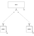
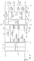
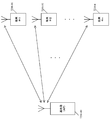
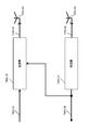
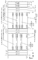
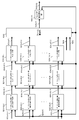
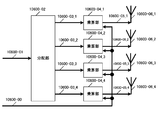
図62は、空間多重MIMO方式の概要を説明する図である。図のMIMO方式は、送信アンテナ数2(TX1、TX2)、受信アンテナ数2(RX1、RX2)、送信変調信号(送信ストリーム)数2のときの送受信装置の構成の一例を示している。
FIG. 62 is a diagram for explaining the outline of the spatial multiplexing MIMO scheme. The MIMO scheme in the figure shows an example of the configuration of a transmission / reception apparatus when the number of transmission antennas is 2 (TX1, TX2), the number of reception antennas is 2 (RX1, RX2), and the number of transmission modulation signals (transmission streams) is 2.
送信装置は、信号生成部、及び、無線処理部を有している。信号生成部は、データを通信路符号化し、MIMOプリコーディング処理を行い、同一周波数(共通の周波数)を用い、同時に送信することの可能な2つの送信信号z1(t)及びz2(t)を生成する。無線処理部は、必要に応じて個々の送信信号を周波数方向に多重化し、つまり、マルチキャリア化(例えば、OFDM(Orthogonal Frequency Division Multiplexing)方式))し、また、受信装置が伝送路歪みや、周波数オフセット、位相ひずみ等の推定を行うためのパイロット信号を挿入する。ただし、パイロット信号は、他のひずみ等を推定してもよいし、また、パイロット信号を、受信装置は、信号検出のために用いてもよい。なお、パイロット信号の受信装置での使用形態はこれに限ったものではない。送信アンテナは、2つのアンテナ(TX1及びTX2)を用いてz1(t)及びz2(t)を送信する。
The transmission device has a signal generation unit and a wireless processing unit. The signal generation unit encodes data, performs MIMO precoding processing, uses the same frequency (common frequency), and transmits two transmission signals z1 (t) and z2 (t) that can be transmitted simultaneously. Generate. The radio processing unit multiplexes individual transmission signals in the frequency direction as necessary, that is, multicarrier (for example, OFDM (Orthogonal Frequency Division Multiplexing) method)), and the receiving apparatus performs transmission path distortion, A pilot signal for estimating frequency offset, phase distortion, etc. is inserted. However, other distortions or the like may be estimated for the pilot signal, and the pilot signal may be used by the receiving device for signal detection. Note that the usage form of the pilot signal receiving apparatus is not limited to this. The transmitting antenna transmits z1 (t) and z2 (t) using two antennas (TX1 and TX2).
受信装置は、受信アンテナ(RX1及びRX2)、無線処理部、チャネル変動推定部、及び信号処理部を含む。受信アンテナ(RX1)は、送信装置の2つの送信アンテナ(TX1及びTX2)から送信された信号を受信する。チャネル変動推定部は、パイロット信号を用いチャネル変動値を推定し、チャネル変動の推定値を信号処理部に供給する。信号処理部は、2本の受信アンテナで受信した信号と推定されたチャネル値に基づいて、z1(t)及びz2(t)に含まれるデータを復元し、これを1つの受信データとして得る。ただし、受信データは「0」「1」の硬判定値であってもよいし、対数尤度または対数尤度比等の軟判定値であってもよい。
The receiving device includes a receiving antenna (RX1 and RX2), a radio processing unit, a channel fluctuation estimation unit, and a signal processing unit. The reception antenna (RX1) receives signals transmitted from the two transmission antennas (TX1 and TX2) of the transmission device. The channel fluctuation estimation unit estimates a channel fluctuation value using the pilot signal, and supplies the channel fluctuation estimation value to the signal processing unit. The signal processing unit restores data included in z1 (t) and z2 (t) based on the signals received by the two receiving antennas and the estimated channel value, and obtains this as one received data. However, the received data may be a hard decision value of “0” or “1”, or may be a soft decision value such as a log likelihood or a log likelihood ratio.
また、符号化方法として、ターボ符号(例えば、Duo-Binary Turbo codes)や、LDPC(Low-Density Parity-Check)符号等の種々の符号化方法が利用されている(非特許文献1~非特許文献6など)。
As encoding methods, various encoding methods such as turbo codes (for example, Duo-Binary Turbo Codes) and LDPC (Low-Density Parity-Check) codes are used (Non-Patent Document 1 to Non-Patent Document 1). Reference 6).
(実施の形態1)
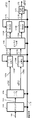
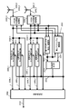
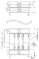
図1は本実施の形態における(例えば、放送局の)送信装置の構成の一例である。
(Embodiment 1)
FIG. 1 shows an example of the configuration of a transmission apparatus (for example, at a broadcasting station) in this embodiment.
データ生成部102は、送信データ10801、制御信号109を入力とし、制御信号109に含まれる誤り訂正符号化の情報、変調方式の情報等の情報に基づき、誤り訂正符号化、変調方式に基づくマッピングを行い、データ伝送用の(直交)ベースバンド信号103を出力する。
Data generation unit 102 receives transmission data 10801 and control signal 109 as input, and performs mapping based on error correction coding and modulation schemes based on information such as error correction coding information and modulation scheme information included in control signal 109. To output (orthogonal) baseband signal 103 for data transmission.
第2プリアンブル生成部105は、第2プリアンブル用送信データ104、制御信号109を入力とし、制御信号109に含まれる第2プリアンブル用の誤り訂正の情報、変調方式の情報等の情報に基づき、誤り訂正符号化、変調方式に基づくマッピングを行い、第2プリアンブルの(直交)ベースバンド信号106を出力する。
Second preamble generation section 105 receives second preamble transmission data 104 and control signal 109 as input, and based on information such as second preamble error correction information and modulation scheme information contained in control signal 109, an error is generated. Mapping based on the correction coding and modulation scheme is performed, and the (orthogonal) baseband signal 106 of the second preamble is output.
制御信号生成部108は、第1プリアンブル用の送信データ107、第2プリアンブル用送信データ104を入力とし、各シンボルの送信方法の情報を制御信号109として出力する。各シンボルの送信方法は、例えば、誤り訂正符号、誤り訂正符号の符号化率、変調方式、ブロック長、フレーム構成、規則的にプリコーディング行列を切り替える送信方法を含む選択した送信方法、パイロットシンボル挿入方法、IFFT(Inverse Fast Fourier Transform)(または、逆フーリエ変換)/FFT(Fast Fourier Transform)(または、フーリエ変換)の情報等、PAPR(Peak to Average Power Ratio)削減方法の情報、ガードインターバル挿入方法の情報である。
The control signal generation unit 108 receives the transmission data 107 for the first preamble and the transmission data 104 for the second preamble, and outputs information on the transmission method of each symbol as the control signal 109. The transmission method of each symbol includes, for example, an error correction code, a coding rate of the error correction code, a modulation method, a block length, a frame configuration, a selected transmission method including a transmission method that regularly switches a precoding matrix, and pilot symbol insertion. Method, IFFT (Inverse Fourier Transform) (or inverse Fourier transform) / FFT (Fast Fourier Transform) (or Fourier transform) information, PAPR (Peak to Average Power Ratio) reduction method information, guard interval insertion method Information.
フレーム構成部110は、データ伝送用の(直交)ベースバンド信号103、第2プリアンブルの(直交)ベースバンド信号106、制御信号109を入力とし、制御信号に含まれるフレーム構成の情報に基づき、周波数、時間軸における並び替えを施し、フレーム構成にしたがった、ストリーム1の(直交)ベースバンド信号111_1、ストリーム2の(直交)ベースバンド信号111_2を出力する。ストリーム1の(直交)ベースバンド信号111_1は、マッピング後の信号、つまり、使用する変調方式に基づくベースバンド信号であり、ストリーム2の(直交)ベースバンド信号111_2は、マッピング後の信号、つまり、使用する変調方式に基づくベースバンド信号である。
The frame configuration unit 110 receives the (orthogonal) baseband signal 103 for data transmission, the (orthogonal) baseband signal 106 of the second preamble, and the control signal 109 as input, and based on the frame configuration information included in the control signal, the frequency Then, rearrangement in the time axis is performed, and (orthogonal) baseband signal 111_1 of stream 1 and (orthogonal) baseband signal 111_2 of stream 2 are output according to the frame configuration. The (orthogonal) baseband signal 111_1 of the stream 1 is a signal after mapping, that is, a baseband signal based on the modulation scheme to be used, and the (orthogonal) baseband signal 111_2 of the stream 2 is a signal after mapping, that is, This is a baseband signal based on the modulation method used.
信号処理部112は、ストリーム1のベースバンド信号111_1、ストリーム2のベースバンド信号111_2、制御信号109を入力とし、制御信号109に含まれる送信方法に基づいた信号処理後の変調信号1(113_1)および信号処理後の変調信号2(113_2)を出力する。
The signal processing unit 112 receives the baseband signal 111_1 of the stream 1, the baseband signal 111_2 of the stream 2, and the control signal 109, and the modulated signal 1 (113_1) after signal processing based on the transmission method included in the control signal 109 And the modulated signal 2 (113_2) after the signal processing is output.
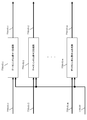
なお、信号処理部では、例えば、プリコーディング、位相変更を用いたMIMO伝送方式(ここでは、MIMO方式と名付ける)、時空間ブロック符号(周波数-空間ブロック符号)を用いたMISO(Multiple-Input Single-Output)伝送方式(ここでは、MISO方式と名付ける)、一つのストリームの変調信号を一つのアンテナから送信するSISO(Single-Input Single-Output)伝送方式、または、SIMO(Single-Input Multiple-Output)伝送方式を用いるものとする。ただし、SISO方式、SIMO方式において、一つのストリームの変調信号を複数のアンテナから送信する場合もある。信号処理部112の動作については、後で詳しく説明する。MIMO伝送方式は、位相変更を施さないMIMO伝送方式であってもよい。
In the signal processing unit, for example, a MIMO transmission system using precoding and phase change (herein referred to as a MIMO system), a MISO (Multiple-Input Single) using a space-time block code (frequency-space block code). -Output) transmission method (herein referred to as MISO method), SISO (Single-Input Single-Output) transmission method that transmits modulated signal of one stream from one antenna, or SIMO (Single-Input Multiple-Output) ) The transmission method shall be used. However, in the SISO system and the SIMO system, a modulated signal of one stream may be transmitted from a plurality of antennas. The operation of the signal processing unit 112 will be described in detail later. The MIMO transmission method may be a MIMO transmission method that does not change the phase.
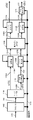
パイロット挿入部114_1は、信号処理後の変調信号1(113_1)、制御信号109を入力とし、制御信号109に含まれるパイロットシンボルの挿入方法に関する情報に基づき、信号処理後の変調信号1(113_1)にパイロットシンボルを挿入し、パイロットシンボル挿入後の変調信号115_1を出力する。
Pilot insertion section 114_1 receives modulated signal 1 (113_1) after signal processing and control signal 109 as input, and modulates signal 1 (113_1) after signal processing based on information relating to the pilot symbol insertion method included in control signal 109. A pilot symbol is inserted into, and modulated signal 115_1 after pilot symbol insertion is output.
パイロット挿入部114_2は、信号処理後の変調信号2(113_2)、制御信号109を入力とし、制御信号109に含まれるパイロットシンボルの挿入方法に関する情報に基づき、信号処理後の変調信号2(113_2)にパイロットシンボルを挿入し、パイロットシンボル挿入後の変調信号115_2を出力する。
Pilot insertion section 114_2 receives modulated signal 2 (113_2) after signal processing and control signal 109 as input, and receives modulated signal 2 (113_2) after signal processing based on information on a pilot symbol insertion method included in control signal 109. A pilot symbol is inserted into, and modulated signal 115_2 after pilot symbol insertion is output.
IFFT(Inverse Fast Fourier Transform)部116_1は、パイロットシンボル挿入後の変調信号115_1、制御信号109を入力とし、制御信号109に含まれるIFFTの方法の情報に基づき、IFFTを施し、IFFT後の信号117_1を出力する。
IFFT (Inverse Fast Fourier Transform) section 116_1 receives modulation signal 115_1 after pilot symbol insertion and control signal 109 as input, performs IFFT based on IFFT method information included in control signal 109, and signal 117_1 after IFFT Is output.
IFFT部116_2は、パイロットシンボル挿入後の変調信号115_2、制御信号109を入力とし、制御信号109に含まれるIFFTの方法の情報に基づき、IFFTを施し、IFFT後の信号117_2を出力する。
IFFT section 116_2 receives modulated signal 115_2 after pilot symbol insertion and control signal 109 as input, performs IFFT based on IFFT method information included in control signal 109, and outputs post-IFFT signal 117_2.
PAPR削減部118_1は、IFFT後の信号117_1、制御信号109を入力とし、制御信号109に含まれるPAPR削減に関する情報に基づき、IFFT後の信号117_1にPAPR削減のための処理を施し、PAPR削減後の信号119_1を出力する。
The PAPR reduction unit 118_1 receives the signal 117_1 after IFFT and the control signal 109 as input, performs a process for PAPR reduction on the signal 117_1 after IFFT based on information on PAPR reduction included in the control signal 109, and after PAPR reduction The signal 119_1 is output.
PAPR削減部118_2は、IFFT後の信号117_2、制御信号109を入力とし、制御信号109に含まれるPAPR削減に関する情報に基づき、IFFT後の信号117_2にPAPR削減のための処理を施し、PAPR削減後の信号119_2を出力する。
The PAPR reduction unit 118_2 receives the signal 117_2 after IFFT and the control signal 109 as input, performs a process for PAPR reduction on the signal 117_2 after IFFT based on information on PAPR reduction included in the control signal 109, and after PAPR reduction The signal 119_2 is output.
ガードインターバル挿入部120_1は、PAPR削減後の信号119_1、制御信号109を入力とし、制御信号109に含まれるガードインターバルの挿入方法に関する情報に基づき、PAPR削減後の信号119_1にガードインターバルを挿入し、ガードインターバル挿入後の信号121_1を出力する。
The guard interval insertion unit 120_1 receives the signal 119_1 after PAPR reduction and the control signal 109 as inputs, and inserts a guard interval into the signal 119_1 after PAPR reduction based on the information on the guard interval insertion method included in the control signal 109. The signal 121_1 after the guard interval is inserted is output.
ガードインターバル挿入部120_2は、PAPR削減後の信号119_2、制御信号109を入力とし、制御信号109に含まれるガードインターバルの挿入方法に関する情報に基づき、PAPR削減後の信号119_2にガードインターバルを挿入し、ガードインターバル挿入後の信号121_2を出力する。
The guard interval insertion unit 120_2 receives the signal 119_2 after the PAPR reduction and the control signal 109 as inputs, and inserts the guard interval into the signal 119_2 after the PAPR reduction based on the information regarding the method of inserting the guard interval included in the control signal 109. A signal 121_2 after insertion of the guard interval is output.
第1プリアンブル挿入部122は、ガードインターバル挿入後の信号121_1、ガードインターバル挿入後の信号121_2、第1プリアンブル用の送信データ107を入力とし、第1プリアンブル用の送信データ107から第1プリアンブルの信号を生成し、ガードインターバル挿入後の信号121_1に対し、第1プリアンブルを付加し、第1プリアンブルを付加した後の信号123_1と、および、ガードインターバル挿入後の信号121_2に対し、第1プリアンブルを付加し、第1プリアンブルを付加した後の信号123_2を出力する。なお、第1プリアンブルの信号は、第1プリアンブルを付加した後の信号123_1、第1プリアンブルを付加した後の信号123_2両者に付加されていてもよく、また、いずれか一方に付加されていてもよい。一方に付加されている場合、付加されている信号の付加されている区間では、付加されていない信号には、ベースバンド信号としてゼロの信号が存在することになる。
The first preamble insertion unit 122 receives the signal 121_1 after the guard interval is inserted, the signal 121_2 after the guard interval is inserted, and the transmission data 107 for the first preamble, and receives the first preamble signal from the transmission data 107 for the first preamble. The first preamble is added to the signal 121_1 after the insertion of the guard interval, and the first preamble is added to the signal 123_1 after the addition of the first preamble and the signal 121_2 after the insertion of the guard interval. The signal 123_2 after adding the first preamble is output. The signal of the first preamble may be added to both the signal 123_1 after the addition of the first preamble and the signal 123_2 after the addition of the first preamble, or may be added to either one of them. Good. In the case where the signal is added to the other side, a zero signal is present as the baseband signal in the signal that is not added in the section where the added signal is added.
無線処理部124_1は、第1プリアンブルを付加した後の信号123_1を入力とし、周波数変換、増幅等の処理が施され、送信信号125_1を出力する。そして、送信信号125_1は、アンテナ126_1から電波として出力される。
The wireless processing unit 124_1 receives the signal 123_1 after the addition of the first preamble, performs processing such as frequency conversion and amplification, and outputs the transmission signal 125_1. Then, the transmission signal 125_1 is output as a radio wave from the antenna 126_1.
無線処理部124_2は、第1プリアンブルを付加した後の信号123_2を入力とし、周波数変換、増幅等の処理が施され、送信信号125_2を出力する。そして、送信信号125_2は、アンテナ126_2から電波として出力される。
The wireless processing unit 124_2 receives the signal 123_2 after the addition of the first preamble, performs processing such as frequency conversion and amplification, and outputs a transmission signal 125_2. Then, the transmission signal 125_2 is output as a radio wave from the antenna 126_2.
なお、本実施の形態では、上述で記載したように、プリコーディング、位相変更を用いたMIMO伝送方式、時空間ブロック符号(Space Time Block codes)(または、周波数-空間ブロック符号(Space Frequency Block codes))を用いたMISO(Multiple-Input Single-Output)伝送方式、SISO(Single-Input Single-Output)伝送方式または、SIMO(Single-Input Single-Output)伝送方式を用いるものとする(詳細は後で説明する)。
In this embodiment, as described above, the MIMO transmission method using precoding and phase change, space-time block code (Space Time Block codes) (or frequency-space block code (Space Frequency Block codes) )) Using MISO (Multiple-Input Single-Output) transmission system, SISO (Single-Input Single-Output) transmission system, or SIMO (Single-Input Single-Output) transmission system Explained in).
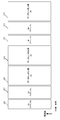
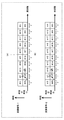
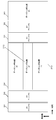
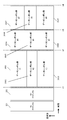
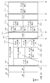
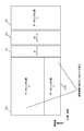
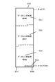
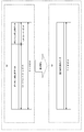
図2から図6は、上述で説明した送信装置が送信する変調信号のフレーム構成の例である。以下では、各フレーム構成の特長について説明する。
2 to 6 are examples of the frame configuration of the modulation signal transmitted by the transmission apparatus described above. Hereinafter, features of each frame configuration will be described.
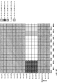
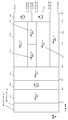
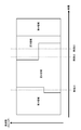
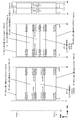
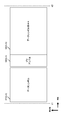
図2は、第1のフレーム構成の例を示している。図2において、縦軸は周波数、横軸は時間であるものとする。そして、OFDM方式等のマルチキャリアを用いた伝送方式を用いているものとするため、縦軸周波数において、複数のキャリアが存在しているものとする。
FIG. 2 shows an example of the first frame configuration. In FIG. 2, the vertical axis represents frequency and the horizontal axis represents time. Since a transmission method using multicarriers such as the OFDM method is used, it is assumed that there are a plurality of carriers in the vertical axis frequency.
図2の201は第1のプリアンブル、202は第2のプリアンブル、203はデータシンボル群#1、204はデータシンボル群#2、205はデータシンボル群#3を示している。
2, 201 indicates a first preamble, 202 indicates a second preamble, 203 indicates a data symbol group # 1, 204 indicates a data symbol group # 2, and 205 indicates a data symbol group # 3.
まず、データシンボル群について説明する。
First, the data symbol group will be described.
映像及び/又はオーディオストリームごとにデータシンボル群を割り当ててもよい。例えば、第1の映像及び/又はオーディオストリームを送信するためのシンボルがデータシンボル群#1(203)、第2の映像及び/又はオーディオストリームを送信するためのシンボルがデータシンボル群#2(204)、第3の映像及び/又はオーディオストリームを送信するためのシンボルがデータシンボル群#3(205)となる。この点については、図2に限ったものではなく、図3,図4、図5、図6でも同様である。この点については、図2に限ったものではなく、図3,図4、図5、図6でも同様である。
A data symbol group may be assigned for each video and / or audio stream. For example, a symbol for transmitting a first video and / or audio stream is a data symbol group # 1 (203), and a symbol for transmitting a second video and / or audio stream is a data symbol group # 2 (204). ), Symbols for transmitting the third video and / or audio stream are data symbol group # 3 (205). This point is not limited to FIG. 2, and the same applies to FIG. 3, FIG. 4, FIG. 5, and FIG. This point is not limited to FIG. 2, and the same applies to FIG. 3, FIG. 4, FIG. 5, and FIG.
また、例えば、DVB-T2(a second generation digital terrestrial television broadcasting system)などの規格におけるPLP(Physical Layer Pipe)のことをデータシンボル群と名付けてもよい。つまり、図2において、データシンボル群#1(203)をPLP#1、データシンボル群#2(204)をPLP#2、データシンボル群#3(205)をPLP#3と名付けてもよい。この点については、図2に限ったものではなく、図3,図4、図5、図6でも同様である。
Further, for example, PLP (Physical Layer Layer Pipe) in a standard such as DVB-T2 (a second generation digital terrestrial television broadcasting system) may be named a data symbol group. That is, in FIG. 2, data symbol group # 1 (203) may be named PLP # 1, data symbol group # 2 (204) may be named PLP # 2, and data symbol group # 3 (205) may be named PLP # 3. This point is not limited to FIG. 2, and the same applies to FIG. 3, FIG. 4, FIG. 5, and FIG.
第1のプリアンブル201、第2のプリアンブル202には、周波数同期、時間同期を行うためのシンボル、例えば、送受信機にとって、同相I-直交Q平面において、信号点配置が既知となるPSK(Phase Shift Keying)のシンボル、受信装置がチャネル変動を推定するためのパイロットシンボル、例えば、送受信機にとって、同相I-直交Q平面において、信号点配置が既知となるPSK(Phase Shift Keying)のシンボル、各データシンボル群の送信方法情報(SISO方式、MISO方式、MIMO方式を識別する情報)を伝送するためのシンボル、各データシンボル群の誤り訂正符号に関する情報(例えば、符号長、符号化率)を伝送するためのシンボル、各データシンボルの変調方式に関する情報(MISO方式、または、MIMO方式の場合、複数のストリームが存在するため、複数の変調方式が指定される)を伝送するためのシンボル、第1及び第2プリアンブルの送信方法情報を伝送するためのシンボル、第1及び第2プリアンブルの誤り訂正符号に関する情報を伝送するためのシンボル、第1及び第2プリアンブルの変調方式に関する情報を伝送するためのシンボル、パイロットシンボルの挿入方法に関する情報を伝送するためのシンボル、PAPR抑圧の方法に関する情報を伝送するためのシンボルなどが含まれているものとする。この点については、図2に限ったものではなく、図3,図4、図5、図6でも同様である。
In the first preamble 201 and the second preamble 202, symbols for frequency synchronization and time synchronization, for example, PSK (Phase Shift) in which the signal point arrangement is known in the in-phase I-orthogonal Q plane for the transceiver. Keying) symbols, pilot symbols for the receiver to estimate channel fluctuations, for example, PSK (Phase Shift Keying) symbols for which the signal point arrangement is known in the in-phase I-orthogonal Q plane for the transceiver, each data Symbols for transmitting symbol group transmission method information (information identifying SISO, MISO, and MIMO) and information (for example, code length, coding rate) on error correction codes of each data symbol group are transmitted. Symbol, information on modulation scheme of each data symbol (MISO or MIMO method) In the case of the equation, since there are a plurality of streams, a plurality of modulation schemes are specified) symbols for transmitting), symbols for transmitting transmission method information of the first and second preambles, first and second Symbol for transmitting information on error correction code of preamble, symbol for transmitting information on modulation scheme of first and second preamble, symbol for transmitting information on pilot symbol insertion method, PAPR suppression method It is assumed that a symbol or the like for transmitting the information on is included. This point is not limited to FIG. 2, and the same applies to FIG. 3, FIG. 4, FIG. 5, and FIG.
図2の特徴的な点は、データシンボル群が、時間分割されて伝送されている点である。
The characteristic point of FIG. 2 is that the data symbol group is transmitted in a time division manner.
なお、図2において、データシンボル群には、パイロットシンボルや制御情報を伝送するためのシンボルが、挿入されていてもよい。また、データシンボル群は、MIMO(伝送)方法およびMISO(伝送)方法に基づくシンボル群であることもある。当然であるが、データシンボル群は、SISO(SIMO)方式のシンボル群であってもよい。この場合、同一時刻、同一(共通)周波数では、複数のストリーム(後で説明するs1,s2)が送信されることになる。この場合、同一時刻、同一(共通)周波数では、複数の変調信号を複数の(異なる)アンテナから送信することになる。そして、この点については、図2に限ったものではなく、図3,図4、図5、図6でも同様である。
In FIG. 2, pilot symbols and symbols for transmitting control information may be inserted into the data symbol group. The data symbol group may be a symbol group based on a MIMO (transmission) method and a MISO (transmission) method. Of course, the data symbol group may be a symbol group of a SISO (SIMO) system. In this case, a plurality of streams (s1 and s2 described later) are transmitted at the same time and the same (common) frequency. In this case, a plurality of modulated signals are transmitted from a plurality of (different) antennas at the same time and the same (common) frequency. This point is not limited to FIG. 2, and the same applies to FIG. 3, FIG. 4, FIG. 5, and FIG.
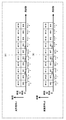
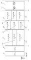
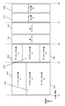
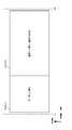
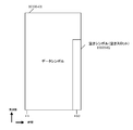
次に、図3について説明する。図3は、第2のフレーム構成の例を示している。図3において、縦軸は周波数、横軸は時間であるものとする。そして、OFDM方式等のマルチキャリアを用いた伝送方式を用いているものとするため、縦軸周波数において、複数のキャリアが存在しているものとする。なお、図3において、図2と同様のものについては、同一番号を付しており、図2と同様に動作するものとする。
Next, FIG. 3 will be described. FIG. 3 shows an example of the second frame configuration. In FIG. 3, the vertical axis represents frequency and the horizontal axis represents time. Since a transmission method using multicarriers such as the OFDM method is used, it is assumed that there are a plurality of carriers in the vertical axis frequency. 3 that are the same as those in FIG. 2 are assigned the same reference numerals and operate in the same manner as in FIG.
図3において特徴的な点は、データシンボル群#2(204)とデータシンボル群#3(205)の(時間的)間に第1プリアンブル301と第2プリアンブル302が挿入されている点である。つまり、「第1プリアンブル、第2プリアンブル、データシンボル群」で形成されるシンボル群をグループと名付けたとき、第1プリアンブル、第2プリアンブル、データシンボル群#1、データシンボル群#2を含む第1のグループと第1プリアンブル、第2プリアンブル、データシンボル群#3を含む第2のグループとが存在し、第1のグループが含むデータシンボル群と第2のグループが含むデータシンボル群の構成が異なることになる。
A characteristic point in FIG. 3 is that the first preamble 301 and the second preamble 302 are inserted between the data symbol group # 2 (204) and the data symbol group # 3 (205) (in time). . That is, when a symbol group formed by “first preamble, second preamble, data symbol group” is named a group, the first preamble, the second preamble, the data symbol group # 1, and the data symbol group # 2 are included. 1 group and the second group including the first preamble, the second preamble, and the data symbol group # 3, and the configuration of the data symbol group included in the first group and the data symbol group included in the second group is Will be different.
このようにした場合、例えば、データシンボル群#1で伝送する映像及び/又はオーディオとデータシンボル群#2で伝送する映像及び/又はオーディオは、映像及び/又はオーディオの符号化の圧縮率が異なるが、同一の「映像及び/又はオーディオ」としてもよい。このようにすると、受信装置は、「データシンボル群#1を復調するか、データシンボル群#2を復調するか」を選択するという簡単な方法で、所望の「映像及び/又はオーディオ」を高い品質で得ることができ、かつ、このとき、プリアンブルを共通化できるため、制御情報の伝送効率を高くすることができるという利点がある。
In this case, for example, the video and / or audio transmitted in the data symbol group # 1 and the video and / or audio transmitted in the data symbol group # 2 have different video and / or audio encoding compression rates. However, the same “video and / or audio” may be used. In this way, the receiving apparatus increases the desired “video and / or audio” by a simple method of selecting “demodulate data symbol group # 1 or demodulate data symbol group # 2”. Since it can be obtained with quality and the preamble can be shared at this time, there is an advantage that the transmission efficiency of control information can be increased.
ただし、これに従わず、データシンボル群#1で伝送する映像及び/又はオーディオは、データシンボル#2で伝送する映像及び/又はオーディオと異なるものであってもよい。
However, the video and / or audio transmitted in the data symbol group # 1 may be different from the video and / or audio transmitted in the data symbol # 2 without following this.
また、データシンボル群#1を送信するための送信方法とデータシンボル群#2を送信するための送信方法とを同一とし、データシンボル群#3を送信するための送信方法とデータシンボル群#1を送信するための送信方法(データシンボル群#2を送信するための送信方法)とを異なるようにすることが容易となる。
Also, the transmission method for transmitting data symbol group # 1 is the same as the transmission method for transmitting data symbol group # 2, and the transmission method for transmitting data symbol group # 3 and data symbol group # 1 are the same. Can be easily made different from the transmission method for transmitting (the transmission method for transmitting data symbol group # 2).
後で説明するが、データシンボル群にはパイロットシンボルが挿入されているものとする。このとき、パイロットシンボルの挿入方法は、送信方法により異なる。なお、送信する変調信号の数が異なることがあるので、送信方法ごとに、データシンボル群をまとめることによって、パイロットシンボル挿入による、伝送効率の低下を防ぐことができる可能性がある。
As will be described later, it is assumed that pilot symbols are inserted in the data symbol group. At this time, the pilot symbol insertion method differs depending on the transmission method. Since the number of modulated signals to be transmitted may differ, it is possible to prevent a decrease in transmission efficiency due to pilot symbol insertion by collecting data symbol groups for each transmission method.
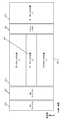
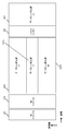
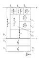
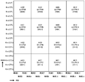
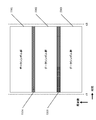
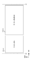
次に、図4について説明する。図4は、第3のフレーム構成の例を示している。図4において、縦軸は周波数、横軸は時間であるものとする。そして、OFDM方式等のマルチキャリアを用いた伝送方式を用いているものとするため、縦軸周波数において、複数のキャリアが存在するものとする。なお、図4において、図2と同様に動作するものについては、同一番号を付しており、図2と同様に動作するものとする。
Next, FIG. 4 will be described. FIG. 4 shows an example of the third frame configuration. In FIG. 4, the vertical axis represents frequency and the horizontal axis represents time. Since a transmission scheme using multicarriers such as the OFDM scheme is used, it is assumed that there are a plurality of carriers in the vertical axis frequency. 4 that operate in the same manner as in FIG. 2 are given the same reference numerals and operate in the same manner as in FIG.
図4において特徴的な点は、データシンボル群#1とデータシンボル群#2が周波数分割されており、加えて、「データシンボル群#1(401_1)およびデータシンボル群#2(402)」と「データシンボル群#3(403)」が時間分割されている点である。つまり、データシンボル群は、周波数分割と時間分割の併用することで伝送されることになる。
A characteristic point in FIG. 4 is that data symbol group # 1 and data symbol group # 2 are frequency-divided, and in addition, “data symbol group # 1 (401_1) and data symbol group # 2 (402)”. “Data symbol group # 3 (403)” is time-divided. That is, the data symbol group is transmitted by using both frequency division and time division.
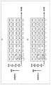
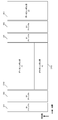
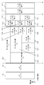
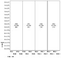
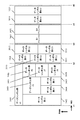
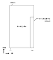
次に、図5について説明する。図5は、第4のフレーム構成の例を示している。図5において、縦軸は周波数、横軸は時間であるものとする。そして、OFDM方式等のマルチキャリアを用いた伝送方式を用いているものとするため、縦軸周波数において、複数のキャリアが存在するものとする。なお、図5において、図2、図4と同様に動作するものについては、同一番号を付しており、図2、図4と同様に動作するものとする。
Next, FIG. 5 will be described. FIG. 5 shows an example of the fourth frame configuration. In FIG. 5, the vertical axis represents frequency and the horizontal axis represents time. Since a transmission scheme using multicarriers such as the OFDM scheme is used, it is assumed that there are a plurality of carriers in the vertical axis frequency. 5 that operate in the same manner as in FIGS. 2 and 4 are denoted by the same reference numerals, and operate in the same manner as in FIGS.
図5において特徴的な点は、図4と同様、データシンボル群#1とデータシンボル群#2が周波数分割されており、加えて、「データシンボル群#1(401_1)およびデータシンボル群#2(402)」と「データシンボル群#3(403)」が時間分割されている点である。つまり、データシンボル群は、周波数分割と時間分割の併用することで伝送されることになる。
In FIG. 5, as in FIG. 4, the data symbol group # 1 and the data symbol group # 2 are frequency-divided. In addition, “data symbol group # 1 (401_1) and data symbol group # 2 (402) ”and“ data symbol group # 3 (403) ”are time-divided. That is, the data symbol group is transmitted by using both frequency division and time division.
加えて、図5において、「データシンボル群#1(401_1、401_2)およびデータシンボル#2(402)」とデータシンボル群#3(403)の(時間的)間に第1プリアンブル301と第2プリアンブル302が挿入されている点である。つまり、「第1プリアンブル、第2プリアンブル、データシンボル群」で形成されるシンボル群をグループと名付けたとき、第1プリアンブル、第2プリアンブル、データシンボル群#1、データシンボル群#2を含む第1のグループと、第1プリアンブル、第2プリアンブル、データシンボル群#3を含む第2のグループとが存在し、第1のグループが含むデータシンボル群と第2のグループが含むデータシンボル群の構成が異なることになる。
In addition, in FIG. 5, the first preamble 301 and the second preamble are between the “data symbol group # 1 (401_1, 401_2) and data symbol # 2 (402)” and the data symbol group # 3 (403) (in time). The preamble 302 is inserted. That is, when a symbol group formed by “first preamble, second preamble, data symbol group” is named a group, the first preamble, the second preamble, the data symbol group # 1, and the data symbol group # 2 are included. 1 group and a second group including a first preamble, a second preamble, and a data symbol group # 3, and a configuration of a data symbol group included in the first group and a data symbol group included in the second group Will be different.
このようにした場合、例えば、データシンボル群#1で伝送する映像及び/又はオーディオとデータシンボル群#2で伝送する映像及び/又はオーディオは、映像及び/又はオーディオの符号化の圧縮率が異なるが、同一の「映像及び/又はオーディオ」としてもよい。このようにすると、受信装置は、「データシンボル群#1を復調するか、データシンボル群#2を復調するか」を選択するという簡単な方法で、所望の「映像及び/又はオーディオ」を高い品質で得ることができ、かつ、このとき、プリアンブルを共通化できるため、制御情報の伝送効率を高くすることができるという利点がある。
In this case, for example, the video and / or audio transmitted in the data symbol group # 1 and the video and / or audio transmitted in the data symbol group # 2 have different video and / or audio encoding compression rates. However, the same “video and / or audio” may be used. In this way, the receiving apparatus increases the desired “video and / or audio” by a simple method of selecting “demodulate data symbol group # 1 or demodulate data symbol group # 2”. Since it can be obtained with quality and the preamble can be shared at this time, there is an advantage that the transmission efficiency of control information can be increased.
ただし、これに従わず、データシンボル群#1で伝送する映像及び/又はオーディオは、データシンボル#2で伝送する映像及び/又はオーディオと異なるものであってもよい。
However, the video and / or audio transmitted in the data symbol group # 1 may be different from the video and / or audio transmitted in the data symbol # 2 without following this.
また、データシンボル群#1を送信するための送信方法とデータシンボル群#2を送信するための送信方法を同一とし、データシンボル群#3を送信するための伝送方法とデータシンボル群#1を送信するための送信方法(データシンボル群#2を送信するための送信方法)を異なるようにすることが容易となる。
Also, the transmission method for transmitting data symbol group # 1 and the transmission method for transmitting data symbol group # 2 are the same, and the transmission method for transmitting data symbol group # 3 and data symbol group # 1 are It becomes easy to make the transmission method for transmission (transmission method for transmitting data symbol group # 2) different.
後で説明するが、データシンボル群にはパイロットシンボルが挿入されているものとする。このとき、パイロットシンボルの挿入方法は、送信方法により異なる。なお、送信する変調信号の数が異なることがあるので、送信方法ごとに、データシンボル群をまとめることによって、パイロットシンボル挿入による、伝送効率の低下を防ぐことができる可能性がある。
As will be described later, it is assumed that pilot symbols are inserted in the data symbol group. At this time, the pilot symbol insertion method differs depending on the transmission method. Since the number of modulated signals to be transmitted may differ, it is possible to prevent a decrease in transmission efficiency due to pilot symbol insertion by collecting data symbol groups for each transmission method.
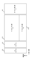
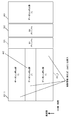
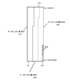
次に、図6について説明する。図6は、第5のフレーム構成の例を示している。図6において、縦軸は周波数、横軸は時間であるものとする。そして、OFDM方式等のマルチキャリアを用いた伝送方式を用いているものとするため、縦軸周波数において、複数のキャリアが存在するものとする。なお、図6において、図2、図4と同様に動作するものについては、同一番号を付しており、図2、図4と同様に動作するものとする。
Next, FIG. 6 will be described. FIG. 6 shows an example of the fifth frame configuration. In FIG. 6, the vertical axis represents frequency and the horizontal axis represents time. Since a transmission scheme using multicarriers such as the OFDM scheme is used, it is assumed that there are a plurality of carriers in the vertical axis frequency. 6 that operate in the same manner as in FIGS. 2 and 4 are denoted by the same reference numerals, and operate in the same manner as in FIGS.
図6において特徴的な点は、図4、図5と同様、データシンボル群#1とデータシンボル群#2が周波数分割されており、加えて、「データシンボル群#1(401_1)およびデータシンボル群#2(402)」と「データシンボル群#3(403)」が時間分割されている点である。つまり、データシンボル群は、周波数分割と時間分割の併用することで伝送されることになる。
In FIG. 6, a characteristic point is that, similarly to FIGS. 4 and 5, the data symbol group # 1 and the data symbol group # 2 are frequency-divided, and in addition, “data symbol group # 1 (401_1) and data symbol Group # 2 (402) "and" Data symbol group # 3 (403) "are time-divided. That is, the data symbol group is transmitted by using both frequency division and time division.
加えて、図6において、「データシンボル群#1(401_1、401_2)およびデータシンボル#2(402)」とデータシンボル群#3(403)の(時間的)間にパイロットシンボルが挿入されている点である。
In addition, in FIG. 6, pilot symbols are inserted between (in terms of time) “data symbol group # 1 (401_1, 401_2) and data symbol # 2 (402)” and data symbol group # 3 (403). Is a point.
このようにした場合、例えば、データシンボル群#1で伝送する映像及び/又はオーディオとデータシンボル群#2で伝送する映像及び/又はオーディオは、映像及び/又はオーディオの符号化の圧縮率が異なるが、同一の「映像及び/又はオーディオ」としてもよい。このようにすると、受信装置は、「データシンボル群#1を復調するか、データシンボル群#2を復調するか」を選択するという簡単な方法で、所望の「映像及び/又はオーディオ」を高い品質で得ることができ、かつ、このとき、プリアンブルを共通化できるため、制御情報の伝送効率を高くすることができるという利点がある。
In this case, for example, the video and / or audio transmitted in the data symbol group # 1 and the video and / or audio transmitted in the data symbol group # 2 have different video and / or audio encoding compression rates. However, the same “video and / or audio” may be used. In this way, the receiving apparatus increases the desired “video and / or audio” by a simple method of selecting “demodulate data symbol group # 1 or demodulate data symbol group # 2”. Since it can be obtained with quality and the preamble can be shared at this time, there is an advantage that the transmission efficiency of control information can be increased.
ただし、これに従わず、データシンボル群#1で伝送する映像及び/又はオーディオは、データシンボル#2で伝送する映像及び/又はオーディオと異なるものであってもよい。
However, the video and / or audio transmitted in the data symbol group # 1 may be different from the video and / or audio transmitted in the data symbol # 2 without following this.
また、データシンボル群#1を送信するための送信方法とデータシンボル群#2を送信するための送信方法を同一とし、データシンボル群#3を送信するための伝送方法とデータシンボル群#1を送信するための送信方法(データシンボル群#2を送信するための送信方法)を異なるようにすることが容易となる。
Also, the transmission method for transmitting data symbol group # 1 and the transmission method for transmitting data symbol group # 2 are the same, and the transmission method for transmitting data symbol group # 3 and data symbol group # 1 are It becomes easy to make the transmission method for transmission (transmission method for transmitting data symbol group # 2) different.
後で説明するが、データシンボル群にはパイロットシンボルが挿入されているものとする。このとき、パイロットシンボルの挿入方法は、送信方法により異なる。なお、送信する変調信号の数が異なることがあるので、送信方法ごとに、データシンボル群をまとめることによって、パイロットシンボル挿入による、伝送効率の低下を防ぐことができる可能性がある。
As will be described later, it is assumed that pilot symbols are inserted in the data symbol group. At this time, the pilot symbol insertion method differs depending on the transmission method. Since the number of modulated signals to be transmitted may differ, it is possible to prevent a decrease in transmission efficiency due to pilot symbol insertion by collecting data symbol groups for each transmission method.
なお、MISO方式またはMIMO方式の場合、各送信アンテナから送信する各変調信号にパイロットシンボルを挿入することになる。
In the case of the MISO system or the MIMO system, a pilot symbol is inserted into each modulation signal transmitted from each transmission antenna.
そして、図6のようにパイロットシンボル601を挿入することで、受信装置は各データシンボル群を検波、復調するためのチャネル推定を高精度に行うことができる。また、データシンボルの送信方法が切り替わった際、受信装置は、送信方法に適した受信信号のゲインを調整しなければならないが、パイロットシンボル601により、容易にゲイン調整を行うことができる、という利点を得ることができる。
Then, by inserting pilot symbols 601 as shown in FIG. 6, the receiving apparatus can perform channel estimation for detecting and demodulating each data symbol group with high accuracy. In addition, when the data symbol transmission method is switched, the receiving apparatus must adjust the gain of the reception signal suitable for the transmission method. However, the pilot symbol 601 can easily adjust the gain. Can be obtained.
なお、図4、図5、図6において、例えば、データシンボル群#1で伝送する映像及び/又はオーディオとデータシンボル群#2で伝送する映像及び/又はオーディオは、映像及び/又はオーディオの符号化の圧縮率が異なるが、同一の「映像及び/又はオーディオ」としてもよい。このようにすると、受信装置は、「データシンボル群#1を復調するか、データシンボル群#2を復調するか」を選択するという簡単な方法で、所望の「映像及び/又はオーディオ」を高い品質で得ることができ、かつ、このとき、プリアンブルを共通化できるため、制御情報の伝送効率を高くすることができるという利点がある。ただし、これに従わず、データシンボル群#1で伝送する映像及び/又はオーディオは、データシンボル#2で伝送する映像及び/又はオーディオと異なるものであってもよい。
4, 5, and 6, for example, video and / or audio transmitted in the data symbol group # 1 and video and / or audio transmitted in the data symbol group # 2 are codes of video and / or audio. The same “video and / or audio” may be used. In this way, the receiving apparatus increases the desired “video and / or audio” by a simple method of selecting “demodulate data symbol group # 1 or demodulate data symbol group # 2”. Since it can be obtained with quality and the preamble can be shared at this time, there is an advantage that the transmission efficiency of control information can be increased. However, the video and / or audio transmitted in the data symbol group # 1 may be different from the video and / or audio transmitted in the data symbol # 2 without following this.
図4、図5、図6において、周波数分割したデータシンボル群の後に時分割したデータシンボル群を配置する例を示しているが、これに限ったののではなく、時分割したデータシンボル群の後に周波数分割したデータシンボル群を配置してもよい。このとき、図5の例では、時分割したデータシンボル群と周波数分割したデータシンボル群の間に第1プリアンブル、第2プリアンブルが挿入されることになる。ただし、それ以外のシンボルが挿入されてもよい。そして、図6の例では、時分割したデータシンボル群と周波数分割したデータシンボル群の間にパイロットシンボルが挿入されることになる。ただし、それ以外のシンボルが挿入されてもよい。
4, 5, and 6, an example is shown in which a time-division data symbol group is arranged after a frequency-division data symbol group. However, the present invention is not limited to this. A data symbol group that is frequency-divided later may be arranged. At this time, in the example of FIG. 5, the first preamble and the second preamble are inserted between the time-division data symbol group and the frequency-division data symbol group. However, other symbols may be inserted. In the example of FIG. 6, pilot symbols are inserted between the time-divided data symbol group and the frequency-divided data symbol group. However, other symbols may be inserted.
本実施の形態における特長的な点について説明する。
The characteristic points in this embodiment will be described.
上述で述べたように、図2から図6のフレーム構成には、それぞれ、利点が存在している。したがって、送信装置は、データ(ストリーム)の圧縮率や種類、送信方法の組み合わせ方法、端末に提供したいサービスの方法により、図2から図6のいずれかのフレーム構成を選択し、制御情報、パイロットシンボル、データシンボルなどのシンボルを送信するものとする。
As described above, each of the frame configurations of FIGS. 2 to 6 has advantages. Therefore, the transmission apparatus selects one of the frame configurations in FIG. 2 to FIG. 6 according to the compression rate and type of data (stream), the combination method of transmission methods, and the service method desired to be provided to the terminal, and controls information, pilot Symbols such as symbols and data symbols are transmitted.
これを実現するために、送信装置(図1)は、フレーム構成に関する情報を第1プリアンブルまたは第2プリアンブルに受信装置(端末)に伝えるための「フレーム構成に関する情報」が含まれているとよい。
In order to realize this, the transmission apparatus (FIG. 1) may include “information on the frame configuration” for transmitting the information on the frame configuration to the reception device (terminal) in the first preamble or the second preamble. .
例えば、「フレーム構成に関する情報」として、v0,v1,v2の3ビットを割り当てたとき、送信装置が図2のフレーム構成で変調信号を送信する場合、(v0,v1,v2)を(0,0,0)とし、「フレーム構成に関する情報」を送信装置は送信する。
For example, when 3 bits of v0, v1, and v2 are assigned as “frame configuration information”, when the transmitting apparatus transmits a modulated signal with the frame configuration of FIG. 2, (v0, v1, v2) is set to (0, 0,0), and the transmitting apparatus transmits “information on frame configuration”.
送信装置が図3のフレーム構成で変調信号を送信する場合、(v0,v1,v2)を(0,0,1)とし、「フレーム構成に関する情報」を送信装置は送信する。
When the transmission apparatus transmits a modulated signal with the frame configuration of FIG. 3, (v0, v1, v2) is set to (0, 0, 1), and the transmission apparatus transmits “information regarding the frame configuration”.
送信装置が図4のフレーム構成で変調信号を送信する場合、(v0,v1,v2)を(0,1,0)とし、「フレーム構成に関する情報」を送信装置は送信する。
When the transmitting apparatus transmits a modulated signal with the frame configuration of FIG. 4, (v0, v1, v2) is set to (0, 1, 0), and the transmitting apparatus transmits “information regarding the frame configuration”.
送信装置が図5のフレーム構成で変調信号を送信する場合、(v0,v1,v2)を(0,1,1)とし、「フレーム構成に関する情報」を送信装置は送信する。
When the transmitting apparatus transmits a modulated signal with the frame configuration of FIG. 5, (v0, v1, v2) is set to (0, 1, 1), and the transmitting apparatus transmits “information regarding the frame configuration”.
送信装置が図5のフレーム構成で変調信号を送信する場合、(v0,v1,v2)を(1,0,0)とし、「フレーム構成に関する情報」を送信装置は送信する。
When the transmitting apparatus transmits a modulated signal with the frame configuration of FIG. 5, (v0, v1, v2) is set to (1, 0, 0), and the transmitting apparatus transmits “information regarding the frame configuration”.
そして、受信装置は、「フレーム構成に関する情報」により、送信装置が送信した変調信号のフレーム構成の概要を知ることができる。
And the receiving device can know the outline of the frame configuration of the modulated signal transmitted by the transmitting device from the “information on the frame configuration”.
上で説明したように、データシンボル群は、SISO(またはSIMO)方式、MISO方式、MIMO方式のいずれかのシンボルとなる。以下では、特に、MISO方式、MIMO方式について説明する。
As described above, the data symbol group is a symbol of any one of the SISO (or SIMO) system, the MISO system, and the MIMO system. In the following, in particular, the MISO method and the MIMO method will be described.
時空間ブロック符号(周波数-空間ブロック符号)を用いたMISO(伝送)方式について説明する。
A description will be given of a MISO (transmission) system using a space-time block code (frequency-space block code).
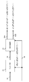
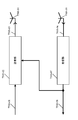
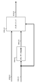
図1の信号処理部112が、時空間ブロック符号(Space-Time Block Codes)を用いた伝送方法を行う場合の構成について、図7を用いて説明する。
A configuration when the signal processing unit 112 in FIG. 1 performs a transmission method using space-time block codes (Space-Time Block Codes) will be described with reference to FIG.
マッピング部702は、データ信号(誤り訂正符号化後のデータ)701、制御信号706を入力とし、制御信号706に含まれる変調方式に関連する情報に基づき、マッピングを行い、マッピング後の信号703を出力する。例えば、マッピング後の信号703は、s0,s1,s2,s3,・・・,s(2i),s(2i+1),・・・の順に並んでいるものとする(iは、0以上の整数とする)。
Mapping section 702 receives data signal (data after error correction coding) 701 and control signal 706 as input, performs mapping based on information related to the modulation method included in control signal 706, and outputs mapped signal 703. Output. For example, it is assumed that the mapped signal 703 is arranged in the order of s0, s1, s2, s3,..., S (2i), s (2i + 1),. And).
MISO(Multiple Input Multiple Output)処理部704は、マッピング後の信号703、制御信号706を入力とし、制御信号706がMISO方式で送信することを指示している場合、MISO処理後の信号705Aおよび705Bを出力する。例えば、MISO処理後の信号705Aはs0,s1,s2,s3,・・・,s(2i),s(2i+1),・・・となり、MISO処理後の信号705Bは-s1*,s0*,-s3*,s2*・・・,-s(2i+1)*,s(2i)*,・・・となる。なお、「*」は複素共役を意味する(例えば、s0*はs0の複素共役となる)。
A MISO (Multiple Input Multiple Output) processing unit 704 receives the mapped signal 703 and the control signal 706 as input, and when the control signal 706 instructs transmission using the MISO method, the signals 705A and 705B after the MISO processing. Is output. For example, the signal 705A after MISO processing is s0, s1, s2, s3,..., S (2i), s (2i + 1),..., And the signal 705B after MISO processing is −s1 * , s0 * , −s3 * , s2 * ..., −s (2i + 1) * , s (2i) * ,. Note that “ * ” means a complex conjugate (for example, s0 * is a complex conjugate of s0).
このとき、MISO処理後の信号705Aおよび705Bが、それぞれ図1の信号処理後の変調信号1(113_1)および信号処理後の変調信号2(113_2)に相当する。なお、時空間ブロック符号の方法は上述の説明に限ったものではない。
At this time, signals 705A and 705B after MISO processing correspond to modulated signal 1 (113_1) after signal processing and modulated signal 2 (113_2) after signal processing in FIG. 1, respectively. The space-time block code method is not limited to the above description.
そして、信号処理後の変調信号1(113_1)は、所定の処理が施され、アンテナ126_1から電波として、送信される。また、信号処理後の変調信号2(113_2)は、所定の処理が施され、アンテナ126_2から電波として、送信される。
The modulated signal 1 (113_1) after the signal processing is subjected to predetermined processing and transmitted as a radio wave from the antenna 126_1. The modulated signal 2 (113_2) after the signal processing is subjected to predetermined processing and transmitted as a radio wave from the antenna 126_2.
図8は、図7とは異なる時空間ブロック符号(Space-Time Block Codes)を用いた伝送方法を行う場合の構成である。
FIG. 8 shows a configuration when a transmission method using space-time block codes (Space-Time Block Codes) different from FIG. 7 is performed.
マッピング部702は、データ信号(誤り訂正符号化後のデータ)701、制御信号706を入力とし、制御信号706に含まれる変調方式に関連する情報に基づき、マッピングを行い、マッピング後の信号703を出力する。例えば、マッピング後の信号703は、s0,s1,s2,s3,・・・,s(2i),s(2i+1),・・・の順に並んでいるものとする(iは、0以上の整数とする)。
Mapping section 702 receives data signal (data after error correction coding) 701 and control signal 706 as input, performs mapping based on information related to the modulation method included in control signal 706, and outputs mapped signal 703. Output. For example, it is assumed that the mapped signal 703 is arranged in the order of s0, s1, s2, s3,..., S (2i), s (2i + 1),. And).
MISO(Multiple Input Multiple Output)処理部704は、マッピング後の信号703、制御信号706を入力とし、制御信号706がMISO方式で送信することを指示している場合、MISO処理後の信号705Aおよび705Bを出力する。例えば、MISO処理後の信号705Aはs0,-s1*,s2,-s3*,・・・,s(2i),-s(2i+1)*,・・・となり、MISO処理後の信号705Bはs1,s0*,s3,s2*・・・,s(2i+1),s(2i)*,・・・となる。なお、「*」は複素共役を意味する。例えば、s0*はs0の複素共役となる。
A MISO (Multiple Input Multiple Output) processing unit 704 receives the mapped signal 703 and the control signal 706 as input, and when the control signal 706 instructs transmission using the MISO method, the signals 705A and 705B after the MISO processing. Is output. For example, the signal 705A after MISO processing is s0, -s1 * , s2, -s3 * , ..., s (2i), -s (2i + 1) * , ..., and the signal 705B after MISO processing is s1 , S0 * , s3, s2 * ..., S (2i + 1), s (2i) * ,. “ * ” Means a complex conjugate. For example, s0 * is a complex conjugate of s0.
このとき、MISO処理後の信号705Aおよび705Bが、それぞれ図1の信号処理後の変調信号1(113_1)および信号処理後の変調信号2(113_2)に相当する。なお、時空間ブロック符号の方法は上述の説明に限ったものではない。
At this time, signals 705A and 705B after MISO processing correspond to modulated signal 1 (113_1) after signal processing and modulated signal 2 (113_2) after signal processing in FIG. 1, respectively. The space-time block code method is not limited to the above description.
そして、信号処理後の変調信号1(113_1)は、所定の処理が施され、アンテナ126_1から電波として、送信される。また、信号処理後の変調信号2(113_2)は、所定の処理が施され、アンテナ126_2から電波として、送信される。
The modulated signal 1 (113_1) after the signal processing is subjected to predetermined processing and transmitted as a radio wave from the antenna 126_1. The modulated signal 2 (113_2) after the signal processing is subjected to predetermined processing and transmitted as a radio wave from the antenna 126_2.
次に、MIMO方式の一例として、プリコーディング、位相変更、パワー変更を適用したMIMO方式について説明する。ただし、複数のストリームを複数のアンテナから送信する方法はこれに限ったものではなく、他の方式であっても、本実施の形態は実施することが可能である。
Next, as an example of the MIMO system, a MIMO system to which precoding, phase change, and power change are applied will be described. However, the method of transmitting a plurality of streams from a plurality of antennas is not limited to this, and the present embodiment can be implemented even with other methods.
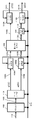
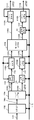
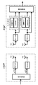
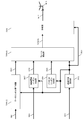
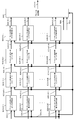
図1の信号処理部112が、MIMO方式を用いた伝送方法を行う場合の構成について、図9から図17を用いて説明する。
A configuration when the signal processing unit 112 in FIG. 1 performs a transmission method using the MIMO scheme will be described with reference to FIGS.
図9の符号化部1102は、情報1101および、制御信号1112を入力とし、制御信号1112に含まれる符号化率、符号長(ブロック長)の情報に基づき、符号化を行い、符号化後のデータ1103を出力する。
The encoding unit 1102 in FIG. 9 receives the information 1101 and the control signal 1112 as input, performs encoding based on the information of the encoding rate and code length (block length) included in the control signal 1112, and performs encoding. Data 1103 is output.
マッピング部1104は、符号化後のデータ1103、制御信号1112を入力とする。そして、制御信号1112が、伝送方式として、二つのストリームを送信することを指定したものとする。加えて、制御信号1112が二つのストリームの各変調方式として、変調方式αと変調方式βを指定したものとする。なお、変調方式αはxビットのデータを変調する変調方式、変調方式βはyビットのデータを変調する変調方式とする。例えば16QAM(16 Quadrature Amplitude Modulation)の場合、4ビットのデータを変調する変調方式であり、64QAM(64 Quadrature Amplitude Modulation)の場合、6ビットのデータを変調する変調方式である。
The mapping unit 1104 receives the encoded data 1103 and the control signal 1112 as inputs. Then, it is assumed that the control signal 1112 designates transmission of two streams as the transmission method. In addition, it is assumed that the control signal 1112 designates the modulation method α and the modulation method β as the modulation methods of the two streams. The modulation method α is a modulation method that modulates x-bit data, and the modulation method β is a modulation method that modulates y-bit data. For example, 16QAM (16QQuadrature Amplitude Modulation) is a modulation method that modulates 4-bit data, and 64QAM (64 Quadrature Amplitude Modulation) is a modulation method that modulates 6-bit data.
すると、マッピング部1104は、x+yビットのデータのうちのxビットのデータに対し、変調方式αで変調し、ベースバンド信号s1(t)1105Aを生成、出力し、また、残りのyビットのデータのデータに対し、変調方式βで変調し、ベースバンド信号s2(t)1105Bを出力する(なお、図9では、マッピング部を一つとしているが、これとは別の構成として、s1(t)を生成するためのマッピング部とs2(t)を生成するためのマッピング部が別々に存在していてもよい。このとき、符号化後のデータ1103は、s1(t)を生成するためのマッピング部とs2(t)を生成するためのマッピング部に振り分けられることになる)。
Then, the mapping unit 1104 modulates the x-bit data of the x + y-bit data with the modulation scheme α, generates and outputs a baseband signal s 1 (t) 1105A, and also outputs the remaining y-bit data The data of the data is modulated by the modulation method β and the baseband signal s 2 (t) 1105B is output (in FIG. 9, only one mapping unit is provided. The mapping unit for generating 1 (t) and the mapping unit for generating s 2 (t) may exist separately, and at this time, the encoded data 1103 includes s 1 (t). And a mapping unit for generating s 2 (t).
なお、s1(t)およびs2(t)は複素数で表現され(ただし、複素数、実数、いずれであってもよい)、また、tは時間である。なお、OFDM(Orthogonal Frequency Division Multiplexing)等のマルチキャリアを用いた伝送方式を用いている場合、s1およびs2は、s1(f)およびs2(f)のように周波数fの関数、または、s1(t,f)およびs2(t,f)のように時間t、周波数fの関数と考えることもできる。
Note that s 1 (t) and s 2 (t) are expressed by complex numbers (however, they may be complex numbers or real numbers), and t is time. When a transmission method using multicarrier such as OFDM (Orthogonal Frequency Division Multiplexing) is used, s 1 and s 2 are functions of the frequency f such as s 1 (f) and s 2 (f), Alternatively, it can be considered as a function of time t and frequency f, such as s 1 (t, f) and s 2 (t, f).
以降では、ベースバンド信号、プリコーディング行列、位相変更等を時間tの関数として説明しているが、周波数fの関数、時間tおよび周波数fの関数と考えてもよい。
Hereinafter, the baseband signal, precoding matrix, phase change, and the like are described as functions of time t, but may be considered as functions of frequency f, functions of time t, and frequency f.
したがって、ベースバンド信号、プリコーディング行列、位相変更等をシンボル番号iの関数として説明を進めている場合もあるが、この場合、時間tの関数、周波数fの関数、時間tおよび周波数fの関数と考えればよい。つまり、シンボル、ベースバンド信号を、時間軸方向で生成し、配置してもよいし、周波数軸方向で生成し、配置してもよい。また、シンボル、ベースバンド信号を、時間軸方向および周波数軸方向で生成し、配置してもよい。
Therefore, there are cases where the description is made with a baseband signal, precoding matrix, phase change, etc. as a function of symbol number i. In this case, a function of time t, a function of frequency f, a function of time t and frequency f I think that. That is, symbols and baseband signals may be generated and arranged in the time axis direction, or may be generated and arranged in the frequency axis direction. Further, symbols and baseband signals may be generated and arranged in the time axis direction and the frequency axis direction.
パワー変更部1106A(パワー調整部1106A)は、ベースバンド信号s1(t)1105A、および、制御信号1112を入力とし、制御信号1112に基づき、実数P1を設定し、P1×s1(t)をパワー変更後の信号1107Aとして出力する。なお、P1を実数としているが、複素数であってもよい。
The power changing unit 1106A (power adjusting unit 1106A) receives the baseband signal s 1 (t) 1105A and the control signal 1112 as input, sets a real number P 1 based on the control signal 1112, and sets P 1 × s 1 ( t) is output as the signal 1107A after the power change. Note that although P 1 is a real number, it may be a complex number.
同様に、パワー変更部1106B(パワー調整部1106B)は、ベースバンド信号s2(t)1105B、および、制御信号512を入力とし、実数P2を設定し、P2×s2(t)をパワー変更後の信号1107Bとして出力する。なお、P2を実数としているが、複素数であってもよい。
Similarly, power changing section 1106B (power adjusting section 1106B) receives baseband signal s 2 (t) 1105B and control signal 512, sets real number P 2, and sets P 2 × s 2 (t). It is output as a signal 1107B after power change. Incidentally, although the P 2 a real number, it may be a complex number.
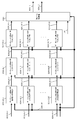
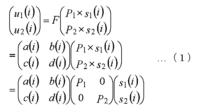
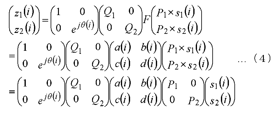
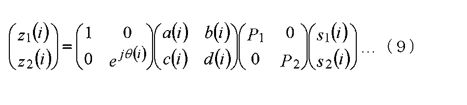
重み付け合成部1108は、パワー変更後の信号1107A、パワー変更後の信号1107B、および、制御信号1112を入力とし、制御信号1112に基づき、プリコーディング行列F(またはF(i))を設定する。スロット番号(シンボル番号)をiとすると、重み付け合成部1108は、以下の演算を行う。
The weighting synthesis unit 1108 receives the signal 1107A after power change, the signal 1107B after power change, and the control signal 1112, and sets a precoding matrix F (or F (i)) based on the control signal 1112. When the slot number (symbol number) is i, the weighting synthesis unit 1108 performs the following calculation.
ここで、a(i)、b(i)、c(i)、d(i)は、複素数で表現でき(実数であってもよい)、a(i)、b(i)、c(i)、d(i)のうち、3つ以上が0(ゼロ)であってはならない。なお、プリコーディング行列はiの関数であってもよいし、iの関数でなくてもよい。そして、プリコーディング行列がiの関数のとき、プリコーディング行列がスロット番号(シンボル番号)により切り替わることになる。
Here, a (i), b (i), c (i), and d (i) can be expressed by complex numbers (may be real numbers), and a (i), b (i), and c (i ), D (i), three or more must not be 0 (zero). The precoding matrix may be a function of i or may not be a function of i. When the precoding matrix is a function of i, the precoding matrix is switched by the slot number (symbol number).
そして、重み付け合成部1108は、式(1)におけるu1(i)を重み付け合成後の信号1109Aとして出力し、式(1)におけるu2(i)を重み付け合成後の信号1109Bとして出力する。
Then, the weighting / combining unit 1108 outputs u 1 (i) in Expression (1) as a signal 1109A after weighted composition, and outputs u 2 (i) in Expression (1) as a signal 1109B after weighted composition.
パワー変更部1110Aは、重み付け合成後の信号1109A(u1(i))、および、制御信号512を入力とし、制御信号1112に基づき、実数Q1を設定し、Q1×u1(t)をパワー変更後の信号1111A(z1(i))として出力する(なお、Q1を実数としているが、複素数であってもよい)。
The power changing unit 1110A receives the weighted combined signal 1109A (u 1 (i)) and the control signal 512, sets a real number Q 1 based on the control signal 1112, and Q 1 × u 1 (t) Is output as a signal 1111A (z 1 (i)) after the power change (Q 1 is a real number, but it may be a complex number).
同様に、パワー変更部1110Bは、重み付け合成後の信号1109B(u2(i))、および、制御信号1112を入力とし、制御信号512に基づき、実数Q2を設定し、Q2×u2(t)をパワー変更後の信号1111B(z2(i))として出力する(なお、Q2を実数としているが、複素数であってもよい)。
Similarly, the power changing unit 1110B receives the weighted combined signal 1109B (u 2 (i)) and the control signal 1112 as input, sets a real number Q 2 based on the control signal 512, and sets Q 2 × u 2. (T) is output as a signal 1111B (z 2 (i)) after power change (note that Q 2 is a real number, but may be a complex number).
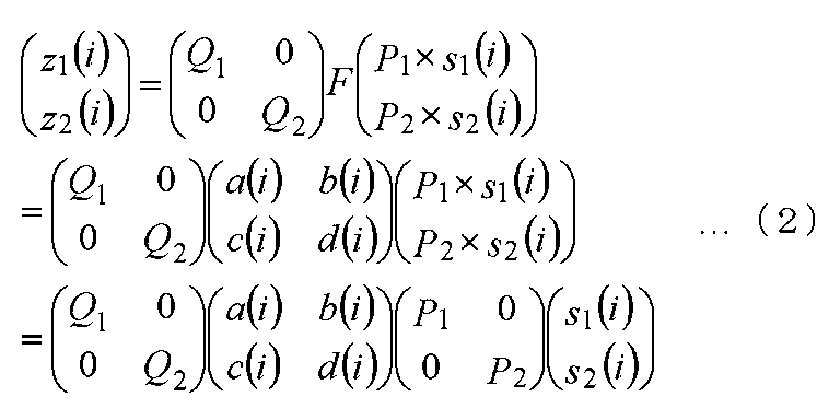
したがって、以下の式が成立する。
Therefore, the following formula is established.
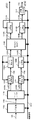
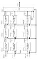
次に、図9とは異なる二つのストリームを送信する場合の伝送方法について、図10を用いて説明する。なお、図10において、図9と同様に動作するものについては、同一符号を付している。
Next, a transmission method in the case of transmitting two streams different from those in FIG. 9 will be described with reference to FIG. 10 that operate in the same manner as in FIG. 9 are denoted by the same reference numerals.
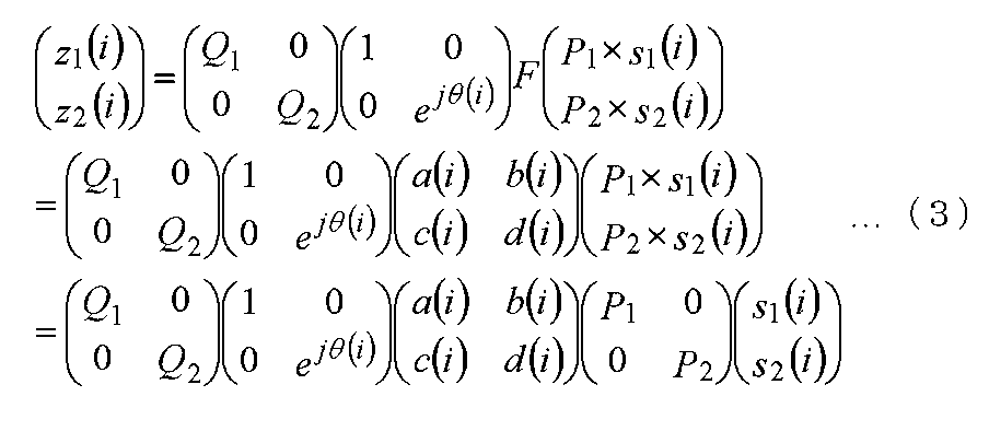
位相変更部1161は、式(1)におけるu2(i)を重み付け合成後の信1109Bおよび制御信号1112を入力とし、制御信号1112に基づき、式(1)におけるu2(i)を重み付け合成後の信号1109Bの位相を変更する。したがって、式(1)におけるu2(i)を重み付け合成後の信号1109Bの位相を変更後の信号は、ejθ(i)×u2(i)とあらわされ、ejθ(i)×u2(i)が位相変更後の信号1162として、位相変更部1161は、出力する(jは虚数単位)。なお、変更する位相の値は、θ(i)のようにiの関数であることが特徴的な部分となる。
The phase changing unit 1161 receives u 2 (i) in the equation (1) as a signal 1109B after the weighted synthesis and the control signal 1112 and inputs u 2 (i) in the equation (1) based on the control signal 1112. The phase of the later signal 1109B is changed. Therefore, the signal after changing the phase of the signal 1109B after the weighted synthesis of u 2 (i) in Equation (1) is expressed as e jθ (i) × u 2 (i), and e jθ (i) × u 2 (i) is output as the signal 1162 after the phase change, and the phase change unit 1161 outputs (j is an imaginary unit). Note that the phase value to be changed is a characteristic part that is a function of i, such as θ (i).
そして、図10のパワー変更部1110Aおよび1110Bは、入力信号のパワー変更をそれぞれ行う。したがって、図10におけるパワー変更部1110Aおよび1110Bのそれぞれの出力z1(i)、z2(i)は、次式のようにあらわされる。
And the power change parts 1110A and 1110B of FIG. 10 perform the power change of an input signal, respectively. Therefore, the outputs z 1 (i) and z 2 (i) of the power changing units 1110A and 1110B in FIG. 10 are expressed by the following equations.
なお、式(3)を実現する方法として、図10と異なる構成として、図11がある。図10と図11の異なる点は、パワー変更部と位相変更部の順番が入れ替わっている点である。パワー変更を行う、位相変更を行うという機能自身はかわらない。このとき、z1(i)、z2(i)は、次式のようにあらわされる。
As a method for realizing Expression (3), FIG. 11 is a configuration different from FIG. The difference between FIG. 10 and FIG. 11 is that the order of the power changing unit and the phase changing unit is switched. The function of changing power or changing phase does not change. At this time, z 1 (i) and z 2 (i) are expressed as follows.
式(3)および式(4)における変更する位相の値θ(i)は、例えば、θ(i+1)―θ(i)が固定値となるように設定すると、直接波が支配的な電波伝搬環境において、受信装置は、良好なデータの受信品質が得られる可能性が高い。ただし、変更する位相の値θ(i)の与え方は、この例に限ったものではない。
When the phase value θ (i) to be changed in the equations (3) and (4) is set so that, for example, θ (i + 1) −θ (i) is a fixed value, the direct wave is dominant. In the environment, the reception device is likely to obtain good data reception quality. However, the method of giving the phase value θ (i) to be changed is not limited to this example.
図9から図11において、パワー変更部の一部(または、すべて)が存在する場合を例に説明したが、パワー変更部の一部がない場合も考えられる。
9 to 11, the case where a part (or all) of the power change unit exists has been described as an example, but there may be a case where there is no part of the power change unit.
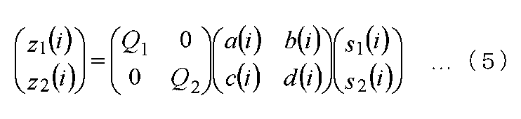
例えば、図9において、パワー変更部1106A(パワー調整部1106A)、パワー変更部1106B(パワー調整部1106B)が存在しない場合、z1(i)およびz2(i)は以下のようにあらわされる。
For example, in FIG. 9, when the power changing unit 1106A (power adjusting unit 1106A) and the power changing unit 1106B (power adjusting unit 1106B) are not present, z 1 (i) and z 2 (i) are expressed as follows. .
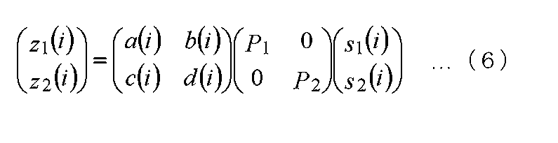
また、図9において、パワー変更部1110A(パワー調整部1110A)、パワー変更部1110B(パワー調整部1110B)が存在しない場合、z1(i)およびz2(i)は以下のようにあらわされる。
Further, in FIG. 9, when there is no power changing unit 1110A (power adjusting unit 1110A) and power changing unit 1110B (power adjusting unit 1110B), z 1 (i) and z 2 (i) are expressed as follows. .
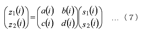
また、図9において、パワー変更部1106A(パワー調整部1106A)、パワー変更部1106B(パワー調整部1106B)、パワー変更部1110A(パワー調整部1110A)、パワー変更部1110B(パワー調整部1110B)が存在しない場合、z1(i)およびz2(i)は以下のようにあらわされる。
In FIG. 9, a power changing unit 1106A (power adjusting unit 1106A), a power changing unit 1106B (power adjusting unit 1106B), a power changing unit 1110A (power adjusting unit 1110A), and a power changing unit 1110B (power adjusting unit 1110B). If not present, z 1 (i) and z 2 (i) are expressed as follows:
また、図10または図11において、パワー変更部1106A(パワー調整部1106A)、パワー変更部1106B(パワー調整部1106B)が存在しない場合、z1(i)およびz2(i)は以下のようにあらわされる。
Further, in FIG. 10 or FIG. 11, when there is no power changing unit 1106A (power adjusting unit 1106A) and power changing unit 1106B (power adjusting unit 1106B), z 1 (i) and z 2 (i) are as follows: Appears.
また、図10または図11において、パワー変更部1110A(パワー調整部1110A)、パワー変更部1110B(パワー調整部1110B)が存在しない場合、z1(i)およびz2(i)は以下のようにあらわされる。
Further, in FIG. 10 or FIG. 11, when there is no power changing unit 1110A (power adjusting unit 1110A) and power changing unit 1110B (power adjusting unit 1110B), z 1 (i) and z 2 (i) are as follows: Appears.
また、図10または図11において、パワー変更部1106A(パワー調整部1106A)、パワー変更部1106B(パワー調整部1106B)、パワー変更部1110A(パワー調整部1110A)、パワー変更部1110B(パワー調整部1110B)が存在しない場合、z1(i)およびz2(i)は以下のようにあらわされる。
10 or 11, the power change unit 1106A (power adjustment unit 1106A), the power change unit 1106B (power adjustment unit 1106B), the power change unit 1110A (power adjustment unit 1110A), and the power change unit 1110B (power adjustment unit). When 1110B) is not present, z 1 (i) and z 2 (i) are expressed as follows:
次に、図9から図11とは異なる二つのストリームを送信する場合の伝送方法について、図12を用いて説明する。なお、図12において、図9から図11と同様に動作するものについては、同一符号を付しており、説明は省略する。
Next, a transmission method in the case of transmitting two streams different from those in FIGS. 9 to 11 will be described with reference to FIG. 12 that operate in the same manner as in FIGS. 9 to 11 are denoted by the same reference numerals and description thereof is omitted.
図12において、特徴的な点は、位相変更部1151が挿入されている点である。
In FIG. 12, a characteristic point is that a phase changing unit 1151 is inserted.
位相変更部1151は、ベースバンド信号s2(i)1105Bおよび制御信号1112を入力とし、制御信号1112に基づき、ベースバンド信号s2(i)1105Bの位相を変更する。このとき、位相変更の値をejλ(i)とする(jは虚数単位)。なお、変更する位相の値は、λ(i)のようにiの関数であることが特徴的な部分となる。
The phase changing unit 1151 receives the baseband signal s 2 (i) 1105B and the control signal 1112 as input, and changes the phase of the baseband signal s 2 (i) 1105B based on the control signal 1112. At this time, the value of the phase change is set to e jλ (i) (j is an imaginary unit). Note that the phase value to be changed is a characteristic part that is a function of i, such as λ (i).
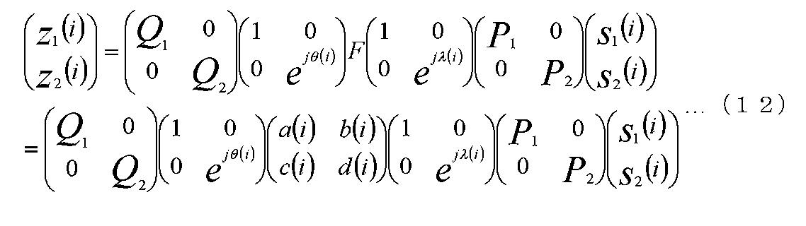
すると、式(1)から式(10)と同様に考えると、図12の出力信号となるz1(i)、z2(i)は、次式のようにあらわされる。
Then, when considered in the same manner as Expressions (1) to (10), z 1 (i) and z 2 (i) that are output signals in FIG. 12 are expressed by the following expressions.
なお、式(11)を実現する方法として、図12と異なる構成として、パワー変更部1106Bと位相変更部1151の順番を入れ替える構成がある。パワー変更を行う、位相変更を行うという機能自身はかわらない。このとき、z1(i)、z2(i)は、次式のようにあらわされる。
In addition, as a method for realizing Expression (11), there is a configuration in which the order of the power changing unit 1106B and the phase changing unit 1151 is switched as a configuration different from that in FIG. The function of changing power or changing phase does not change. At this time, z 1 (i) and z 2 (i) are expressed as follows.
当然であるが、式(11)のz1(i)と式(12)のz1(i)は等しく、式(11)のz2(i)と式(12)のz2(i)は等しい。
Of course, equation (11) z 1 (i) and z 1 of the formula (12) (i) are equal, equation (11) z 2 a (i) and Formula (12) z 2 a (i) Are equal.
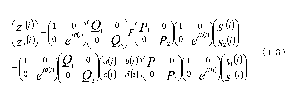
図13は、図12と同様の処理を実現することができる別の構成となる。なお、図13において、図9から図12と同様に動作するものについては、同一符号を付しており、説明は省略する。そして、図12と図13の異なる点は、図12において、パワー変更部1110Bと位相変更部1161の順番が入れ替えたものが図13となる。パワー変更を行う、位相変更を行うという機能自身はかわらない。
FIG. 13 shows another configuration capable of realizing the same processing as in FIG. In FIG. 13, components that operate in the same manner as in FIGS. 9 to 12 are given the same reference numerals, and descriptions thereof are omitted. 12 differs from FIG. 13 in that the order of the power changing unit 1110B and the phase changing unit 1161 is changed in FIG. The function of changing power or changing phase does not change.
すると、式(1)から式(12)と同様に考えると、図13の出力信号となるz1(i)、z2(i)は、次式のようにあらわされる。
Then, when considered in the same manner as Expressions (1) to (12), z 1 (i) and z 2 (i) that are output signals in FIG. 13 are expressed as the following expressions.
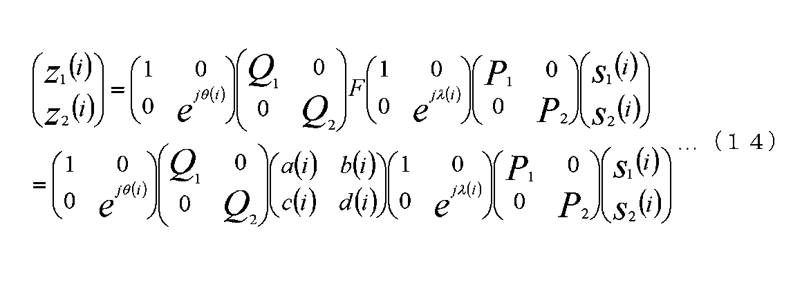
なお、式(13)を実現する方法として、図13と異なる構成として、パワー変更部1106Bと位相変更部1151の順番を入れ替える構成がある。パワー変更を行う、位相変更を行うという機能自身はかわらない。このとき、z1(i)、z2(i)は、次式のようにあらわされる。
In addition, as a method for realizing Expression (13), there is a configuration in which the order of the power changing unit 1106B and the phase changing unit 1151 is switched as a configuration different from FIG. The function of changing power or changing phase does not change. At this time, z 1 (i) and z 2 (i) are expressed as follows.
当然であるが、式(11)のz1(i)と式(12)のz1(i)式(13)のz1(i)と式(14)のz1(i)は等しく、式(11)のz2(i)と式(12)のz2(i)と式(13)のz2(i)と式(14)のz2(i)は等しい。
Naturally, z 1 (i) in formula (11) is equal to z 1 in formula (12) (i) z 1 (i) in formula (13) is equal to z 1 (i) in formula (14), z 2 (i) of formula (11) z 2 (i) and the z 2 of z 2 (i) and formula (13) in equation (12) (i) and formula (14) are equal.
次に、図9から図13とは異なる二つのストリームを送信する場合の伝送方法について、図14を用いて説明する。なお、図14において、図9から図13と同様に動作するものについては、同一符号を付しており、説明は省略する。
Next, a transmission method in the case of transmitting two streams different from those in FIGS. 9 to 13 will be described with reference to FIG. 14 that operate in the same manner as in FIGS. 9 to 13 are denoted by the same reference numerals, and description thereof is omitted.
図14において、特徴的な点は、位相変更部1181と位相変更部1151が挿入されている点である。
In FIG. 14, a characteristic point is that a phase changing unit 1181 and a phase changing unit 1151 are inserted.
位相変更部1151は、ベースバンド信号s2(i)1105Bおよび制御信号1112を入力とし、制御信号1112に基づき、ベースバンド信号s2(i)1105Bの位相を変更する。このとき、位相変更の値をejλ(i)とする(jは虚数単位)。なお、変更する位相の値は、λ(i)のようにiの関数であることが特徴的な部分となる。
The phase changing unit 1151 receives the baseband signal s 2 (i) 1105B and the control signal 1112 as input, and changes the phase of the baseband signal s 2 (i) 1105B based on the control signal 1112. At this time, the value of the phase change is set to e jλ (i) (j is an imaginary unit). Note that the phase value to be changed is a characteristic part that is a function of i, such as λ (i).
また、位相変更部1181は、ベースバンド信号s1(i)1105Aおよび制御信号1112を入力とし、制御信号1112に基づき、ベースバンド信号s1(i)1105Aの位相を変更する。このとき、位相変更の値をejδ(i)とする(jは虚数単位)。なお、変更する位相の値は、δ(i)のようにiの関数であることが特徴的な部分となる。
The phase changing unit 1181 receives the baseband signal s 1 (i) 1105A and the control signal 1112 as input, and changes the phase of the baseband signal s 1 (i) 1105A based on the control signal 1112. At this time, the phase change value is set to e jδ (i) (j is an imaginary unit). The phase value to be changed is a characteristic part that is a function of i, such as δ (i).
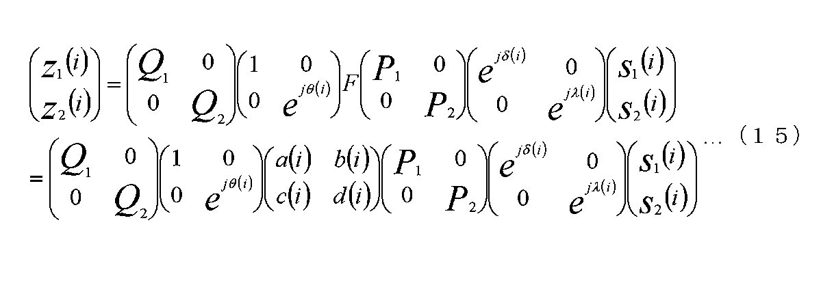
すると、式(1)から式(14)と同様に考えると、図14の出力信号となるz1(i)、z2(i)は、次式のようにあらわされる。
Then, when considered in the same manner as Expression (1) to Expression (14), z 1 (i) and z 2 (i) that are output signals in FIG. 14 are expressed as follows.
なお、式(15)を実現する方法として、図14と異なる構成として、パワー変更部1106Bと位相変更部1151の順番を入れ替え、かつ、パワー変更部1106Aと位相変更部1181の順番を入れ替える構成がある。パワー変更を行う、位相変更を行うという機能自身はかわらない。このとき、z1(i)、z2(i)は、次式のようにあらわされる。
As a method for realizing Expression (15), a configuration different from that in FIG. 14 is a configuration in which the order of the power changing unit 1106B and the phase changing unit 1151 is changed, and the order of the power changing unit 1106A and the phase changing unit 1181 is changed. is there. The function of changing power or changing phase does not change. At this time, z 1 (i) and z 2 (i) are expressed as follows.
当然であるが、式(15)のz1(i)と式(16)のz1(i)は等しく、式(15)のz2(i)と式(16)のz2(i)は等しい。
Of course, equation (15) z 1 (i) and z 1 of the formula (16) (i) z 2 of equal, equation (15) (i) and Formula (16) z 2 a (i) Are equal.
図15は、図14と同様の処理を実現することができる別の構成となる。なお、図15において、図9から図14と同様に動作するものについては、同一符号を付しており、説明は省略する。そして、図14と図15の異なる点は、図14において、パワー変更部1110Bと位相変更部1161の順番が入れ替えたものが図15となる(パワー変更を行う、位相変更を行うという機能自身はかわらない)。
FIG. 15 shows another configuration capable of realizing the same processing as in FIG. 15 that operate in the same manner as in FIGS. 9 to 14 are denoted by the same reference numerals and description thereof is omitted. 14 and FIG. 15 is different from FIG. 14 in that the order of the power changing unit 1110B and the phase changing unit 1161 is changed as shown in FIG. 15 (the function itself for changing the power and changing the phase is Unchanged).
すると、式(1)から式(16)と同様に考えると、図15の出力信号となるz1(i)、z2(i)は、次式のようにあらわされる。
Then, when considered in the same manner as Expression (1) to Expression (16), z 1 (i) and z 2 (i) that are output signals in FIG. 15 are expressed as the following expressions.
なお、式(17)を実現する方法として、図15と異なる構成として、パワー変更部1106Bと位相変更部1151の順番を入れ替え、かつ、パワー変更部1106Aと位相変更部1181の順番を入れ替える構成がある。パワー変更を行う、位相変更を行うという機能自身はかわらない。このとき、z1(i)、z2(i)は、次式のようにあらわされる。
As a method for realizing Expression (17), as a configuration different from that in FIG. 15, the order of the power changing unit 1106B and the phase changing unit 1151 is changed, and the order of the power changing unit 1106A and the phase changing unit 1181 is changed. is there. The function of changing power or changing phase does not change. At this time, z 1 (i) and z 2 (i) are expressed as follows.
当然であるが、式(15)のz1(i)と式(16)のz1(i)式(17)のz1(i)と式(18)のz1(i)は等しく、式(15)のz2(i)と式(16)のz2(i)と式(17)のz2(i)と式(18)のz2(i)は等しい。
Naturally, z 1 (i) in equation (15) is equal to z 1 in equation (16) (i) z 1 (i) in equation (17) is equal to z 1 (i) in equation (18), z 2 (i) of the z 2 (i) and z 2 (i) and formula z 2 (i) and formula (17) in equation (16) (18) of the formula (15) are equal.
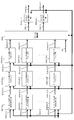
次に、図9から図15とは異なる二つのストリームを送信する場合の伝送方法について、図16を用いて説明する。なお、図16において、図9から図15と同様に動作するものについては、同一符号を付しており、説明は省略する。
Next, a transmission method in the case of transmitting two streams different from those in FIGS. 9 to 15 will be described with reference to FIG. 16 that operate in the same manner as in FIGS. 9 to 15 are denoted by the same reference numerals and description thereof is omitted.
図16において、特徴的な点は、位相変更部1181と位相変更部1151、位相変更部1110Aと位相変更部1110Bが挿入されている点である。
In FIG. 16, a characteristic point is that a phase change unit 1181, a phase change unit 1151, a phase change unit 1110A, and a phase change unit 1110B are inserted.
位相変更部1151は、ベースバンド信号s2(i)1105Bおよび制御信号1112を入力とし、制御信号1112に基づき、ベースバンド信号s2(i)1105Bの位相を変更する。このとき、位相変更の値をejλ(i)とする(jは虚数単位)。なお、変更する位相の値は、λ(i)のようにiの関数であることが特徴的な部分となる。
The phase changing unit 1151 receives the baseband signal s 2 (i) 1105B and the control signal 1112 as input, and changes the phase of the baseband signal s 2 (i) 1105B based on the control signal 1112. At this time, the value of the phase change is set to e jλ (i) (j is an imaginary unit). Note that the phase value to be changed is a characteristic part that is a function of i, such as λ (i).
また、位相変更部1181は、ベースバンド信号s1(i)1105Aおよび制御信号1112を入力とし、制御信号1112に基づき、ベースバンド信号s1(i)1105Aの位相を変更する。このとき、位相変更の値をejδ(i)とする(jは虚数単位)。なお、変更する位相の値は、δ(i)のようにiの関数であることが特徴的な部分となる。
The phase changing unit 1181 receives the baseband signal s 1 (i) 1105A and the control signal 1112 as input, and changes the phase of the baseband signal s 1 (i) 1105A based on the control signal 1112. At this time, the phase change value is set to e jδ (i) (j is an imaginary unit). The phase value to be changed is a characteristic part that is a function of i, such as δ (i).
位相変更部1161は入力信号に対し位相変更を行う。そのときの位相変更値をθ(i)とする。同様に、位相変更部1191は入力信号に対し位相変更を行う。そのときの位相変更値をω(i)とする。
The phase changing unit 1161 changes the phase of the input signal. Let the phase change value at that time be θ (i). Similarly, the phase changing unit 1191 changes the phase of the input signal. Let the phase change value at that time be ω (i).
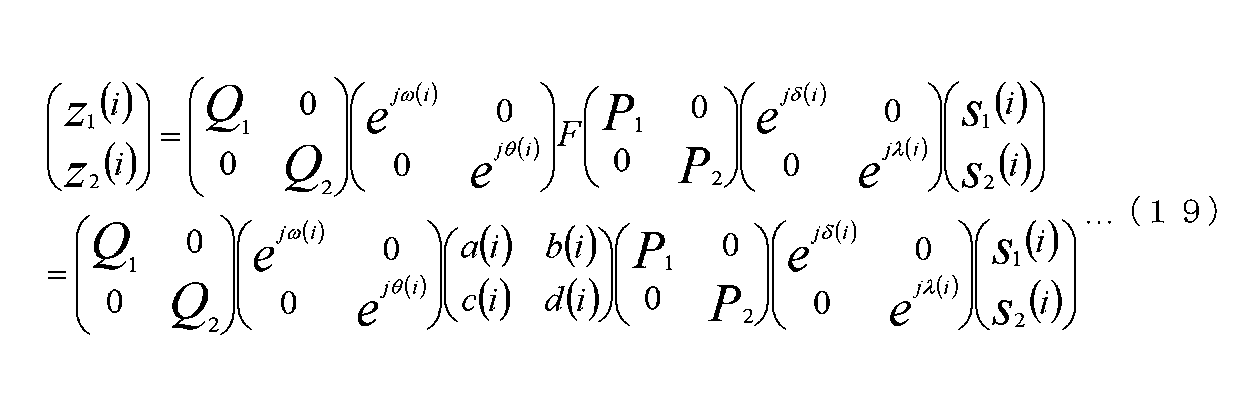
すると、式(1)から式(18)と同様に考えると、図16の出力信号となるz1(i)、z2(i)は、次式のようにあらわされる。
Then, when considered in the same manner as Expression (1) to Expression (18), z 1 (i) and z 2 (i) that are output signals in FIG. 16 are expressed as follows.
なお、式(19)を実現する方法として、図16と異なる構成として、パワー変更部1106Bと位相変更部1151の順番を入れ替え、かつ、パワー変更部1106Aと位相変更部1181の順番を入れ替える構成がある。パワー変更を行う、位相変更を行うという機能自身はかわらない。このとき、z1(i)、z2(i)は、次式のようにあらわされる。
As a method for realizing Expression (19), a configuration different from that in FIG. 16 is a configuration in which the order of the power changing unit 1106B and the phase changing unit 1151 is changed and the order of the power changing unit 1106A and the phase changing unit 1181 is changed. is there. The function of changing power or changing phase does not change. At this time, z 1 (i) and z 2 (i) are expressed as follows.
当然であるが、式(19)のz1(i)と式(20)のz1(i)は等しく、式(19)のz2(i)と式(20)のz2(i)は等しい。
Of course, equation (19) z 1 z 1 of (i) and Formula (20) (i) are equal, equation (19) z 2 (i) and Formula (20) z 2 a (i) Are equal.
図17は、図16と同様の処理を実現することができる別の構成となる。なお、図17において、図9から図16と同様に動作するものについては、同一符号を付しており、説明は省略する。そして、図16と図17の異なる点は、図14において、パワー変更部1110Bと位相変更部1161の順番が入れ替え、かつ、パワー変更部1110Aと位相変更部1191の順番が入れ替えたものが図17となる。パワー変更を行う、位相変更を行うという機能自身はかわらない。
FIG. 17 shows another configuration capable of realizing the same processing as in FIG. In FIG. 17, the same reference numerals are given to components that operate in the same manner as in FIGS. 16 and FIG. 17 are different from FIG. 14 in that the order of the power changing unit 1110B and the phase changing unit 1161 is changed, and the order of the power changing unit 1110A and the phase changing unit 1191 is changed. It becomes. The function of changing power or changing phase does not change.
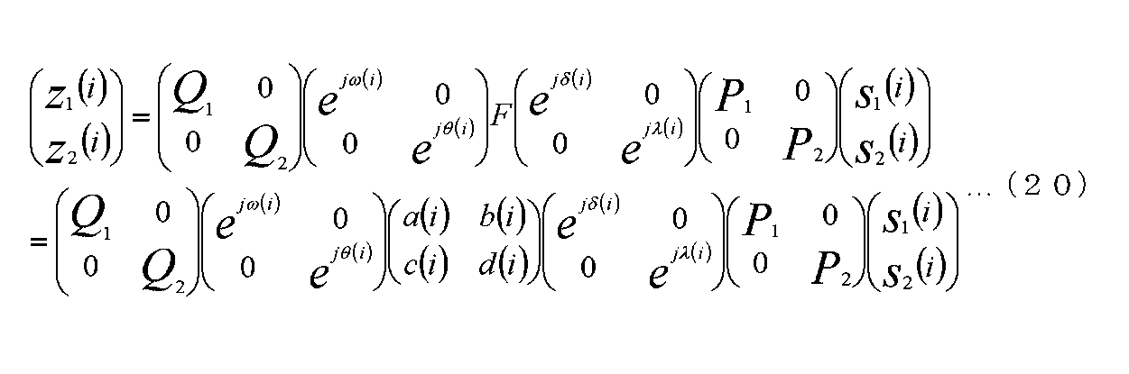
すると、式(1)から式(20)と同様に考えると、図17の出力信号となるz1(i)、z2(i)は、次式のようにあらわされる。
Then, when considered in the same manner as Expressions (1) to (20), z 1 (i) and z 2 (i) that are output signals in FIG. 17 are expressed as follows.
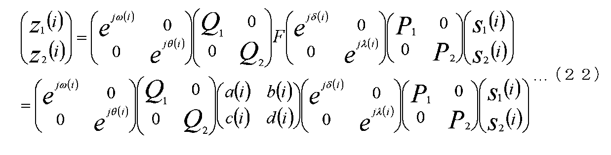
なお、式(21)を実現する方法として、図17と異なる構成として、パワー変更部1106Bと位相変更部1151の順番を入れ替え、かつ、パワー変更部1106Aと位相変更部1181の順番を入れ替える構成がある。パワー変更を行う、位相変更を行うという機能自身はかわらない。このとき、z1(i)、z2(i)は、次式のようにあらわされる。
As a method for realizing Expression (21), a configuration different from that in FIG. 17 is a configuration in which the order of the power changing unit 1106B and the phase changing unit 1151 is changed and the order of the power changing unit 1106A and the phase changing unit 1181 is changed. is there. The function of changing power or changing phase does not change. At this time, z 1 (i) and z 2 (i) are expressed as follows.
当然であるが、式(19)のz1(i)と式(20)のz1(i)式(21)のz1(i)と式(22)のz1(i)は等しく、式(19)のz2(i)と式(20)のz2(i)と式(21)のz2(i)と式(22)のz2(i)は等しい。
Of course, equation (19) z 1 of (i) and z 1 (i) of the formula z 1 (i) formula (20) (21) z 1 of (i) and Formula (22) are equal, z 2 of the formula (19) z 2 a (i) and z 2 of z 2 (i) and formula (21) in equation (20) (i) and formula (22) (i) are equal.
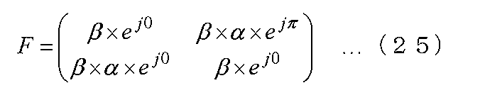
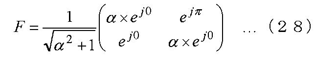
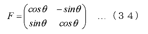
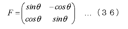
上述において、重み付け合成(プリコーディング)のための行列Fを示しているが、以下で記載するようなプリコーディング行列F(またはF(i))を用いても、本明細書の各実施の形態を実施することができる。
In the above description, the matrix F for weighted synthesis (precoding) is shown. However, each embodiment of the present specification can be used even if a precoding matrix F (or F (i)) as described below is used. Can be implemented.
または、
Or
または、
Or
または、
Or
または、
Or
または、
Or
または、
Or
または、
Or
なお、式(23)、式(24)、式(25)、式(26)、式(27)、式(28)、式(29)、式(30)において、αは実数であってもよいし、虚数であってもよく、βは実数であってもよいし、虚数であってもよい。ただし、αは0(ゼロ)ではない。そして、βも0(ゼロ)ではない。
または、
In the formula (23), formula (24), formula (25), formula (26), formula (27), formula (28), formula (29), and formula (30), α may be a real number. It may be an imaginary number, and β may be a real number or an imaginary number. However, α is not 0 (zero). Β is not 0 (zero).
Or
または、
Or
または、
Or
または、
Or
または、
Or
または、
Or
または、
Or
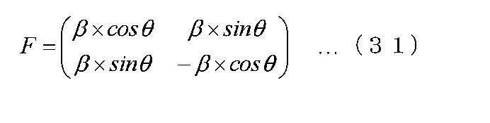
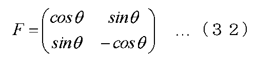
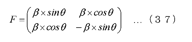
または、
Or
なお、式(31)、式(33)、式(35)、式(37)において、βは実数であってもよいし、虚数であってもよい。ただし、βは0(ゼロ)ではない。
または、
In Expression (31), Expression (33), Expression (35), and Expression (37), β may be a real number or an imaginary number. However, β is not 0 (zero).
Or
または、
Or
または、
Or
または、
Or
または、
Or
または、
Or
または、
Or
または、
Or
または、
Or
または、
Or
または、
Or
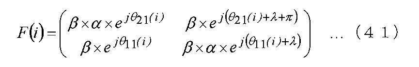
または、
Or
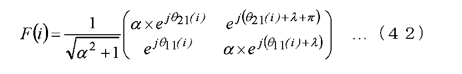
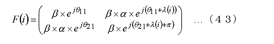
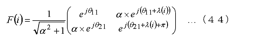
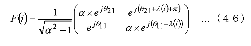
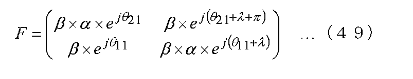
ただし、θ11(i)、θ21(i)、λ(i)はiの関数であり、λは固定の値であり、αは実数であってもよいし、虚数であってもよく、βは実数であってもよいし、虚数であってもよい。ただし、αは0(ゼロ)ではない。そして、βも0(ゼロ)ではない。なお、iは、時間及び周波数のいずれか、または、時間及び周波数の両方である。
However, θ 11 (i), θ 21 (i), and λ (i) are functions of i, λ is a fixed value, α may be a real number or an imaginary number, β may be a real number or an imaginary number. However, α is not 0 (zero). Β is not 0 (zero). Note that i is either time or frequency, or both time and frequency.
または、
Or
または、
Or
または、
Or
または、
Or
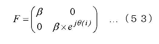
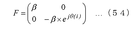
ただし、θ(i)はiの関数であり、βは実数であってもよいし、虚数であってもよい。ただし、βも0(ゼロ)ではない。iは、時間及び周波数のいずれか、または、時間及び周波数の両方である。
However, θ (i) is a function of i, and β may be a real number or an imaginary number. However, β is not 0 (zero). i is either time and frequency or both time and frequency.
また、これら以外のプリコーディング行列を用いても、本明細書の各実施の形態を実施することが可能である。
Also, it is possible to implement each embodiment of the present specification using a precoding matrix other than these.
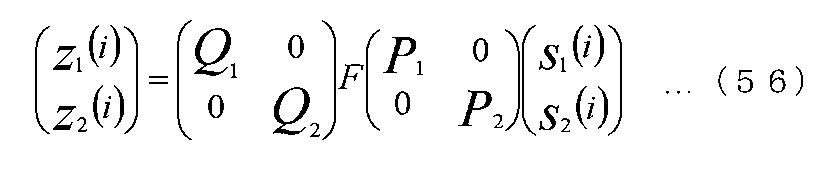
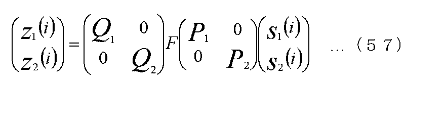
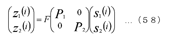
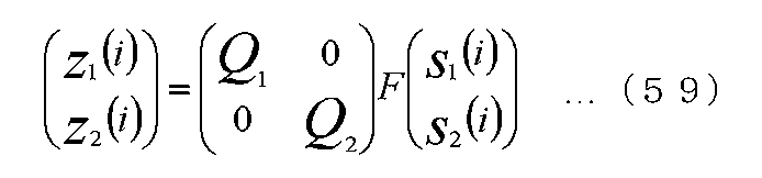
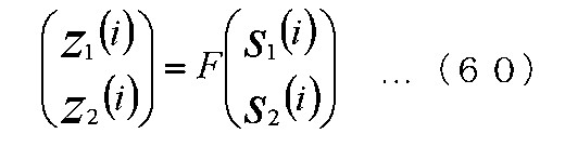
加えて、上述で説明した、位相変更、を行わずに、プリコーディングを行って変調信号を生成し、送信装置は変調信号を送信する方式であってもよい。このとき、z1(i)、z2(i)は次式であらわされる例が考えられる。
In addition, a method may be used in which the modulated signal is generated by performing precoding without performing the phase change described above, and the transmitting apparatus transmits the modulated signal. At this time, examples where z 1 (i) and z 2 (i) are expressed by the following equations are conceivable.
そして、図9から図17で得られたz1(i)、または、式(56)のz1(i)、または、式(57)のz1(i)、または、式(58)のz1(i)、または、式(59)のz1(i)、または、式(60)のz1(i)は、図1の信号処理後の変調信号1(113_1)に相当し、図9から図17で得られたz2(i)、または、式(56)のz2(i)、または、式(57)のz2(i)、または、式(58)のz2(i)、または、式(59)のz2(i)、または、式(60)のz2(i)、は図1の変調信号2(113_2)に相当する。
Then, z 1 obtained in FIG. 17. FIG 9 (i), or, z 1 (i) of formula (56) or, z 1 (i) of formula (57), or, the formula (58) z 1 (i), or, z 1 (i) of formula (59) or, z 1 (i) of formula (60) corresponds to the modulated signal 1 (113_1) after the signal processing of FIG. 1, z 2 obtained in FIG. 17. FIG 9 (i), or, z 2 (i) of formula (56) or, z 2 (i) of formula (57) or, z 2 of the formula (58) (i), or, z 2 (i) of formula (59) or, z 2 (i) of formula (60), corresponds to the modulated signal 2 (113_2) FIG.
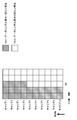
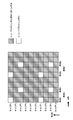
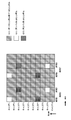
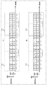
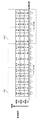
図18から図22は、図9から図17で生成したz1(i)およびz2(i)の配置方法の一例を示している。
18 to 22 show an example of the arrangement method of z 1 (i) and z 2 (i) generated in FIGS. 9 to 17.
図18における(A)はz1(i)の配置方法を示しており、図18における(B)はz2(i)の配置方法を示している。図18における(A)、(B)では、縦軸は時間、横軸は周波数である。
(A) in FIG. 18 shows the arrangement method of z 1 (i), and (B) in FIG. 18 shows the arrangement method of z 2 (i). In FIGS. 18A and 18B, the vertical axis represents time, and the horizontal axis represents frequency.
図18における(A)について説明する。まず、i=0、1、2、3、・・・に対応をするz1(0)、z1(1)、z1(2)、z1(3)、・・・を生成したとき、
z1(0)をキャリア0、時刻1に配置し、
z1(1)をキャリア1、時刻1に配置し、
z1(2)をキャリア2、時刻1に配置し、
・・・
z1(10)をキャリア0、時刻2に配置し、
z1(11)をキャリア1、時刻2に配置し、
z1(12)をキャリア2、時刻2に配置し、
・・・
とする。
(A) in FIG. 18 will be described. First, when z 1 (0), z 1 (1), z 1 (2), z 1 (3),... Corresponding to i = 0, 1, 2, 3,. ,
z 1 (0) is placed at carrier 0, time 1,
z 1 (1) is placed at carrier 1, time 1,
z 1 (2) is placed at carrier 2, time 1,
...
z 1 (10) is placed at carrier 0, time 2,
z 1 (11) is placed at carrier 1, time 2,
z 1 (12) is placed at carrier 2, time 2,
...
And
同様に、図18における(B)では、i=0、1、2、3、・・・に対応をするz2(0)、z2(1)、z2(2)、z2(3)、・・・を生成したとき、
z2(0)をキャリア0、時刻1に配置し、
z2(1)をキャリア1、時刻1に配置し、
z2(2)をキャリア2、時刻1に配置し、
・・・
z2(10)をキャリア0、時刻2に配置し、
z2(11)をキャリア1、時刻2に配置し、
z2(12)をキャリア2、時刻2に配置し、
・・・
とする。
Similarly, in FIG. 18B, z 2 (0), z 2 (1), z 2 (2), z 2 (3) corresponding to i = 0, 1, 2, 3,. ), ...
z 2 (0) is placed at carrier 0, time 1,
z 2 (1) is placed at carrier 1, time 1,
z 2 (2) is placed at carrier 2, time 1,
...
z 2 (10) is placed at carrier 0, time 2,
z 2 (11) is placed at carrier 1, time 2,
z 2 (12) is placed at carrier 2, time 2,
...
And
このとき、i=aのときのz1(a)とz2(a)は、同一周波数、同一時刻、から送信されることになる。そして、図18は、生成したz1(i)とz2(i)を周波数軸方向に優先的に並べる場合の例である。
At this time, z 1 (a) and z 2 (a) when i = a are transmitted from the same frequency and the same time. FIG. 18 shows an example in which the generated z 1 (i) and z 2 (i) are preferentially arranged in the frequency axis direction.
図19における(A)はz1(i)の配置方法を示しており、図19における(B)はz2(i)の配置方法を示している。図19における(A)、(B)では、縦軸は時間、横軸は周波数である。
(A) in FIG. 19 shows the arrangement method of z 1 (i), and (B) in FIG. 19 shows the arrangement method of z 2 (i). In FIGS. 19A and 19B, the vertical axis represents time, and the horizontal axis represents frequency.
図19における(A)について説明する。まず、i=0、1、2、3、・・・に対応をするz1(0)、z1(1)、z1(2)、z1(3)、・・・を生成したとき、
z1(0)をキャリア0、時刻1に配置し、
z1(1)をキャリア1、時刻2に配置し、
z1(2)をキャリア2、時刻1に配置し、
・・・
z1(10)をキャリア2、時刻2に配置し、
z1(11)をキャリア7、時刻1に配置し、
z1(12)をキャリア8、時刻2に配置し、
・・・
とする。
(A) in FIG. 19 will be described. First, when z 1 (0), z 1 (1), z 1 (2), z 1 (3),... Corresponding to i = 0, 1, 2, 3,. ,
z 1 (0) is placed at carrier 0, time 1,
z 1 (1) is placed at carrier 1, time 2,
z 1 (2) is placed at carrier 2, time 1,
...
z 1 (10) is placed at carrier 2, time 2,
z 1 (11) is placed at carrier 7, time 1,
z 1 (12) is placed at carrier 8, time 2,
...
And
同様に、図19における(B)では、i=0、1、2、3、・・・に対応をするz2(0)、z2(1)、z2(2)、z2(3)、・・・を生成したとき、
z2(0)をキャリア0、時刻1に配置し、
z2(1)をキャリア1、時刻2に配置し、
z2(2)をキャリア2、時刻1に配置し、
・・・
z2(10)をキャリア2、時刻2に配置し、
z2(11)をキャリア7、時刻1に配置し、
z2(12)をキャリア8、時刻2に配置し、
・・・
とする。
Similarly, in FIG. 19B, z 2 (0), z 2 (1), z 2 (2), z 2 (3) corresponding to i = 0, 1, 2, 3,. ), ...
z 2 (0) is placed at carrier 0, time 1,
z 2 (1) is placed at carrier 1, time 2,
z 2 (2) is placed at carrier 2, time 1,
...
z 2 (10) is placed at carrier 2, time 2,
z 2 (11) is placed at carrier 7, time 1,
z 2 (12) is placed at carrier 8, time 2,
...
And
このとき、i=aのときのz1(a)とz2(a)は、同一周波数、同一時刻、から送信されることになる。そして、図19は、生成したz1(i)とz2(i)を周波数、時間軸方向にランダムに並べる場合の例である。
At this time, z 1 (a) and z 2 (a) when i = a are transmitted from the same frequency and the same time. FIG. 19 shows an example in which the generated z 1 (i) and z 2 (i) are randomly arranged in the frequency and time axis directions.
図20における(A)はz1(i)の配置方法を示しており、図20における(B)はz2(i)の配置方法を示している。図20における(A)、(B)では、縦軸は時間、横軸は周波数である。
(A) in FIG. 20 shows the arrangement method of z 1 (i), and (B) in FIG. 20 shows the arrangement method of z 2 (i). In FIGS. 20A and 20B, the vertical axis represents time, and the horizontal axis represents frequency.
図20における(A)について説明する。まず、i=0、1、2、3、・・・に対応をするz1(0)、z1(1)、z1(2)、z1(3)、・・・を生成したとき、
z1(0)をキャリア0、時刻1に配置し、
z1(1)をキャリア2、時刻1に配置し、
z1(2)をキャリア4、時刻1に配置し、
・・・
z1(10)をキャリア0、時刻2に配置し、
z1(11)をキャリア2、時刻2に配置し、
z1(12)をキャリア4、時刻2に配置し、
・・・
とする。
(A) in FIG. 20 will be described. First, when z 1 (0), z 1 (1), z 1 (2), z 1 (3),... Corresponding to i = 0, 1, 2, 3,. ,
z 1 (0) is placed at carrier 0, time 1,
z 1 (1) is placed at carrier 2, time 1,
z 1 (2) is placed at carrier 4, time 1,
...
z 1 (10) is placed at carrier 0, time 2,
z 1 (11) is placed at carrier 2, time 2,
z 1 (12) is placed at carrier 4, time 2,
...
And
同様に、図20における(B)では、i=0、1、2、3、・・・に対応をするz2(0)、z2(1)、z2(2)、z2(3)、・・・を生成したとき、
z2(0)をキャリア0、時刻1に配置し、
z2(1)をキャリア2、時刻1に配置し、
z2(2)をキャリア4、時刻1に配置し、
・・・
z2(10)をキャリア0、時刻2に配置し、
z2(11)をキャリア2、時刻2に配置し、
z2(12)をキャリア4、時刻2に配置し、
・・・
とする。
Similarly, in FIG. 20B, z 2 (0), z 2 (1), z 2 (2), z 2 (3) corresponding to i = 0, 1, 2, 3,. ), ...
z 2 (0) is placed at carrier 0, time 1,
z 2 (1) is placed at carrier 2, time 1,
z 2 (2) is placed at carrier 4, time 1,
...
z 2 (10) is placed at carrier 0, time 2,
z 2 (11) is placed at carrier 2, time 2,
z 2 (12) is placed at carrier 4, time 2,
...
And
このとき、i=aのときのz1(a)とz2(a)は、同一周波数、同一時刻、から送信されることになる。そして、図20は、生成したz1(i)とz2(i)を周波数軸方向に優先的に並べる場合の例である。
At this time, z 1 (a) and z 2 (a) when i = a are transmitted from the same frequency and the same time. FIG. 20 shows an example in which the generated z 1 (i) and z 2 (i) are preferentially arranged in the frequency axis direction.
図21における(A)はz1(i)の配置方法を示しており、図21における(B)はz2(i)の配置方法を示している。図21における(A)、(B)では、縦軸は時間、横軸は周波数である。
(A) in FIG. 21 shows the arrangement method of z 1 (i), and (B) in FIG. 21 shows the arrangement method of z 2 (i). In FIGS. 21A and 21B, the vertical axis represents time, and the horizontal axis represents frequency.
図21における(A)について説明する。まず、i=0、1、2、3、・・・に対応をするz1(0)、z1(1)、z1(2)、z1(3)、・・・を生成したとき、
z1(0)をキャリア0、時刻1に配置し、
z1(1)をキャリア1、時刻1に配置し、
z1(2)をキャリア0、時刻2に配置し、
・・・
z1(10)をキャリア2、時刻2に配置し、
z1(11)をキャリア3、時刻2に配置し、
z1(12)をキャリア2、時刻3に配置し、
・・・
とする。
(A) in FIG. 21 will be described. First, when z 1 (0), z 1 (1), z 1 (2), z 1 (3),... Corresponding to i = 0, 1, 2, 3,. ,
z 1 (0) is placed at carrier 0, time 1,
z 1 (1) is placed at carrier 1, time 1,
z 1 (2) is placed at carrier 0, time 2,
...
z 1 (10) is placed at carrier 2, time 2,
z 1 (11) is placed at carrier 3, time 2,
z 1 (12) is placed at carrier 2, time 3,
...
And
同様に、図21における(B)では、i=0、1、2、3、・・・に対応をするz2(0)、z2(1)、z2(2)、z2(3)、・・・を生成したとき、
z2(0)をキャリア0、時刻1に配置し、
z2(1)をキャリア1、時刻1に配置し、
z2(2)をキャリア0、時刻2に配置し、
・・・
z2(10)をキャリア2、時刻2に配置し、
z2(11)をキャリア3、時刻2に配置し、
z2(12)をキャリア2、時刻3に配置し、
・・・
とする。
Similarly, in FIG. 21B, z 2 (0), z 2 (1), z 2 (2), z 2 (3) corresponding to i = 0, 1, 2, 3,. ), ...
z 2 (0) is placed at carrier 0, time 1,
z 2 (1) is placed at carrier 1, time 1,
z 2 (2) is placed at carrier 0, time 2,
...
z 2 (10) is placed at carrier 2, time 2,
z 2 (11) is placed at carrier 3, time 2,
z 2 (12) is placed at carrier 2, time 3,
...
And
このとき、i=aのときのz1(a)とz2(a)は、同一周波数、同一時刻、から送信されることになる。そして、図21は、生成したz1(i)とz2(i)を時間及び周波数軸方向に並べる場合の例である。
At this time, z 1 (a) and z 2 (a) when i = a are transmitted from the same frequency and the same time. FIG. 21 shows an example of arranging the generated z 1 (i) and z 2 (i) in the time and frequency axis directions.
図22における(A)はz1(i)の配置方法を示しており、図22における(B)はz2(i)の配置方法を示している。図22における(A)、(B)では、縦軸は時間、横軸は周波数である。
(A) in FIG. 22 shows the arrangement method of z 1 (i), and (B) in FIG. 22 shows the arrangement method of z 2 (i). In FIGS. 22A and 22B, the vertical axis represents time, and the horizontal axis represents frequency.
図22における(A)について説明する。まず、i=0、1、2、3、・・・に対応をするz1(0)、z1(1)、z1(2)、z1(3)、・・・を生成したとき、
z1(0)をキャリア0、時刻1に配置し、
z1(1)をキャリア0、時刻2に配置し、
z1(2)をキャリア0、時刻3に配置し、
・・・
z1(10)をキャリア2、時刻3に配置し、
z1(11)をキャリア2、時刻4に配置し、
z1(12)をキャリア3、時刻1に配置し、
・・・
とする。
(A) in FIG. 22 will be described. First, when z 1 (0), z 1 (1), z 1 (2), z 1 (3),... Corresponding to i = 0, 1, 2, 3,. ,
z 1 (0) is placed at carrier 0, time 1,
z 1 (1) is placed at carrier 0, time 2,
z 1 (2) is placed at carrier 0, time 3,
...
z 1 (10) is placed at carrier 2, time 3,
z 1 (11) is placed at carrier 2, time 4,
z 1 (12) is placed at carrier 3, time 1,
...
And
同様に、図22における(B)では、i=0、1、2、3、・・・に対応をするz2(0)、z2(1)、z2(2)、z2(3)、・・・を生成したとき、
z2(0)をキャリア0、時刻1に配置し、
z2(1)をキャリア0、時刻2に配置し、
z2(2)をキャリア0、時刻3に配置し、
・・・
z2(10)をキャリア2、時刻3に配置し、
z2(11)をキャリア2、時刻4に配置し、
z2(12)をキャリア3、時刻1に配置し、
・・・
とする。
Similarly, in FIG. 22B, z 2 (0), z 2 (1), z 2 (2), z 2 (3) corresponding to i = 0, 1, 2, 3,. ), ...
z 2 (0) is placed at carrier 0, time 1,
z 2 (1) is placed at carrier 0, time 2,
z 2 (2) is placed at carrier 0, time 3,
...
z 2 (10) is placed at carrier 2, time 3,
z 2 (11) is placed at carrier 2, time 4,
z 2 (12) is placed at carrier 3, time 1,
...
And
このとき、i=aのときのz1(a)とz2(a)は、同一周波数、同一時刻、から送信されることになる。そして、図22は、生成したz1(i)とz2(i)を時間軸方向に優先的に並べる場合の例である。
At this time, z 1 (a) and z 2 (a) when i = a are transmitted from the same frequency and the same time. FIG. 22 shows an example in which the generated z 1 (i) and z 2 (i) are preferentially arranged in the time axis direction.
送信装置は、図18から図22、または、それ以外のシンボル配置方法の、いずれの方法でシンボルを配置してもよい。あくまでも、図18から図22は、シンボル配置の例である。
The transmitting apparatus may arrange symbols by any method of FIGS. 18 to 22 or other symbol arrangement methods. 18 to 22 are only examples of symbol arrangement.
図23は、図1の送信装置が送信した変調信号を受信する受信装置(端末)の構成例である。
FIG. 23 is a configuration example of a receiving device (terminal) that receives the modulated signal transmitted by the transmitting device of FIG.
図23において、OFDM方式関連処理部2303_Xは、アンテナ2301_Xで受信した受信信号2302_Xを入力とし、OFDM方式のための受信側の信号処理を施し、信号処理後の信号2304_Xを出力する。同様に、OFDM方式関連処理部2303_Yは、アンテナ2301_Yで受信した受信信号2302_Yを入力とし、OFDM方式のための受信側の信号処理を施し、信号処理後の信号2304_Yを出力する。
23, an OFDM scheme-related processing unit 2303_X receives the received signal 2302_X received by the antenna 2301_X, performs reception-side signal processing for the OFDM scheme, and outputs a signal 2304_X after the signal processing. Similarly, the OFDM scheme-related processing unit 2303_Y receives the received signal 2302_Y received by the antenna 2301_Y, performs reception-side signal processing for the OFDM scheme, and outputs a signal 2304_Y after signal processing.
第1プリアンブル検出、復号部2311は、信号処理後の信号2304_X、2304_Yを入力とし、第1プリアンブルを検出することで、信号検出、時間周波数同期を行うと同時に、復調、および、誤り訂正復号を行うことで、第1プリアンブルに含まれる制御情報を得、第1プリアンブル制御情報2312を出力する。
The first preamble detection / decoding unit 2311 receives the signal processed signals 2304_X and 2304_Y and detects the first preamble, thereby performing signal detection and time-frequency synchronization, and simultaneously performs demodulation and error correction decoding. As a result, the control information included in the first preamble is obtained, and the first preamble control information 2312 is output.
第2プリアンブル復調部2313は、信号処理後の信号2304_X、2304_Y、および、第1プリアンブル制御情報2312を入力とし、第1プリアンブル制御情報2312に基づき、信号処理を行い、復調(誤り訂正復号を含む)を行い、第2プリアンブル制御情報2314を出力する。
Second preamble demodulation section 2313 receives signals 2304_X and 2304_Y after signal processing and first preamble control information 2312 as input, performs signal processing based on the first preamble control information 2312, and demodulates (including error correction decoding). ) And the second preamble control information 2314 is output.
制御情報生成部2315は、第1プリアンブル制御情報2312、および、第2プリアンブル制御情報2314を入力とし、(受信動作に関係する)制御情報をたばね、制御信号2316として出力する。そして、制御信号2316は、図23に示したように、各部に入力されることになる。
The control information generation unit 2315 receives the first preamble control information 2312 and the second preamble control information 2314, and outputs control information (related to the reception operation) as a spring and a control signal 2316. The control signal 2316 is input to each unit as shown in FIG.
変調信号z1のチャネル変動推定部2305_1は、信号処理後の信号2304_X、制御信号2316を入力とし、送信装置が変調信号z1を送信したアンテナと受信アンテナ2301_X間のチャネル変動を信号処理後の信号2304_Xに含まれるパイロットシンボル等を用いて推定し、チャネル推定信号2306_1を出力する。
Channel fluctuation estimation section 2305_1 of the modulated signal z 1, the signal after the signal processing 2304_X, control signal 2316 as input, transmitting apparatus after the signal processing channel fluctuation between the receiving antenna 2301_X antenna that has transmitted the modulated signal z 1 Estimation is performed using a pilot symbol included in the signal 2304_X, and a channel estimation signal 2306_1 is output.
変調信号z2のチャネル変動推定部2305_2は、信号処理後の信号2304_X、制御信号2316を入力とし、送信装置が変調信号z2を送信したアンテナと受信アンテナ2301_X間のチャネル変動を信号処理後の信号2304_Xに含まれるパイロットシンボル等を用いて推定し、チャネル推定信号2306_2を出力する。
Channel fluctuation estimation section 2305_2 of the modulated signal z 2, the signal after the signal processing 2304_X, control signal 2316 as input, transmitting apparatus after the signal processing channel fluctuation between the receiving antenna 2301_X antenna that has transmitted the modulated signal z 2 Estimation is performed using pilot symbols included in the signal 2304_X, and a channel estimation signal 2306_2 is output.
変調信号z1のチャネル変動推定部2307_1は、信号処理後の信号2304_Y、制御信号2316を入力とし、送信装置が変調信号z1を送信したアンテナと受信アンテナ2301_Y間のチャネル変動を信号処理後の信号2304_Yに含まれるパイロットシンボル等を用いて推定し、チャネル推定信号2308_1を出力する。
Channel fluctuation estimation section 2307_1 of the modulated signal z 1, the signal after the signal processing 2304_Y, control signal 2316 as input, transmitting apparatus after the signal processing channel fluctuation between the receiving antenna 2301_Y antenna that has transmitted the modulated signal z 1 Estimation is performed using pilot symbols included in the signal 2304_Y, and a channel estimation signal 2308_1 is output.
変調信号z2のチャネル変動推定部2307_2は、信号処理後の信号2304_Y、制御信号2316を入力とし、送信装置が変調信号z2を送信したアンテナと受信アンテナ2301_Y間のチャネル変動を信号処理後の信号2304_Yに含まれるパイロットシンボル等を用いて推定し、チャネル推定信号2308_2を出力する。
Channel fluctuation estimation section 2307_2 of the modulated signal z 2, the signal after the signal processing 2304_Y, control signal 2316 as input, transmitting apparatus after the signal processing channel fluctuation between the receiving antenna 2301_Y antenna that has transmitted the modulated signal z 2 Estimation is performed using pilot symbols included in the signal 2304_Y, and a channel estimation signal 2308_2 is output.
信号処理部2309は、信号2306_1、2306_2、2308_1、2308_2、2304_X、2304_Y、および、制御信号2316を入力とし、制御信号2316に含まれている、伝送方式、変調方式、誤り訂正符号化方式、誤り訂正符号化の符号化率及び誤り訂正符号のブロックサイズ等の情報に基づき、復調、復号の処理を行い、受信データ2310を出力する。このとき、上述で説明した伝送方法に基づき他、検波(復調)及び復号が行われることになる。
The signal processing unit 2309 receives the signals 2306_1, 2306_2, 2308_1, 2308_2, 2304_X, 2304_Y and the control signal 2316, and includes the transmission method, modulation method, error correction coding method, error included in the control signal 2316, and the like. Based on information such as the coding rate of the correction coding and the block size of the error correction code, demodulation and decoding are performed, and reception data 2310 is output. At this time, detection (demodulation) and decoding are performed based on the transmission method described above.
なお、受信装置は、制御信号2316から必要としているシンボルを抽出して復調(信号分離、信号検波を含む)、誤り訂正復号を行うことになる。また、受信装置の構成はこれに限ったものではない。
Note that the receiving apparatus extracts necessary symbols from the control signal 2316, performs demodulation (including signal separation and signal detection), and performs error correction decoding. Further, the configuration of the receiving device is not limited to this.
以上のように、送信装置が、図2から図6のフレーム構成のいずれかのフレーム構成を選択できるようにすることで、柔軟な映像情報、柔軟な、放送サービスを、受信装置(視聴者)に提供することができるという利点がある。また、図2から図6の各フレーム構成では、上述のようにそれぞれ利点が存在する。したがって、送信装置が図2から図6のフレーム構成を単独で用いてもよく、そのとき、上述の説明で記載したような効果を得ることができる。
As described above, by enabling the transmission device to select any one of the frame configurations in FIGS. 2 to 6, flexible video information and flexible broadcast services can be received by the reception device (viewer). There is an advantage that can be provided. Further, each frame configuration of FIGS. 2 to 6 has advantages as described above. Therefore, the transmission apparatus may use the frame configurations of FIGS. 2 to 6 alone, and at that time, the effects described in the above description can be obtained.
また、送信装置が、図2から図6のフレーム構成のいずれかを選択する場合、例えば、送信装置をある地域に設置した場合、図2から図6のフレーム構成のいずれかを送信装置を設置時に設定、それを定期的に見直すというようなフレーム構成の切り替えであってもよいし、フレーム送信ごとに、図2から図6のフレーム構成を選択する方法であってもよい。フレーム構成の選択方法については、どのような選択をとってもよい。
In addition, when the transmission apparatus selects any of the frame configurations of FIGS. 2 to 6, for example, when the transmission apparatus is installed in a certain area, any of the frame configurations of FIGS. 2 to 6 is installed. The frame configuration may be switched such that it is sometimes set and periodically reviewed, or the frame configuration shown in FIGS. 2 to 6 may be selected for each frame transmission. Any method for selecting a frame configuration may be used.
なお、図2から図6のフレーム構成において、第1プリアンブルに他のシンボル、例えば、パイロットシンボルやヌルシンボル(シンボルの同相成分が0(ゼロ、直交成分が0(ゼロ)))等が挿入されていてもよい。同様に、第2プリアンブルにパイロットシンボルやヌルシンボル(シンボルの同相成分が0(ゼロ、直交成分が0(ゼロ)))等のシンボルが挿入されていてもよい。また、プリアンブルを第1のプリアンブルと第2プリアンブルで構成しているが、プリアンブルの構成については、これに限ったものではなく、第1のプリアンブル(第1のプリアンブル群)のみで構成されていてもよいし、2つ以上のプリアンブル(プリアンブル群)で構成されていてもよい。なお、プリアンブルの構成については、他の実施の形態のフレーム構成を示しているときについても同様である。
2 to 6, other symbols such as pilot symbols and null symbols (the in-phase component of the symbol is 0 (zero, the quadrature component is 0 (zero))) are inserted in the first preamble. It may be. Similarly, a symbol such as a pilot symbol or a null symbol (the in-phase component of the symbol is 0 (zero, the orthogonal component is 0 (zero))) may be inserted into the second preamble. In addition, the preamble is composed of the first preamble and the second preamble, but the structure of the preamble is not limited to this, and is composed only of the first preamble (first preamble group). Alternatively, it may be composed of two or more preambles (preamble group). It should be noted that the preamble configuration is the same when the frame configuration of another embodiment is shown.
そして、図2から図6のフレーム構成において、データシンボル群を示しているが、他のシンボル、例えば、パイロットシンボル、ヌルシンボル(シンボルの同相成分が0(ゼロ、直交成分が0(ゼロ)))、制御情報シンボル等が挿入されていてもよい。なお、これについては、他の実施の形態のフレーム構成を示しているときについても同様である。
The data symbol group is shown in the frame configurations of FIGS. 2 to 6, but other symbols such as pilot symbols and null symbols (the in-phase component of the symbol is 0 (zero, the quadrature component is 0 (zero)). ), A control information symbol or the like may be inserted. This also applies to the case where the frame configuration of another embodiment is shown.
また、図6のパイロットシンボルにおいて、他のシンボル、例えば、パイロットシンボル、ヌルシンボル(シンボルの同相成分が0(ゼロ、直交成分が0(ゼロ)))、制御情報シンボル、データシンボル等が挿入されていてもよい。なお、これについては、他の実施の形態のフレーム構成を示しているときについても同様である。
In addition, other symbols such as a pilot symbol and a null symbol (the in-phase component of the symbol is 0 (zero, the orthogonal component is 0 (zero))), a control information symbol, a data symbol, and the like are inserted in the pilot symbol of FIG. It may be. This also applies to the case where the frame configuration of another embodiment is shown.
(実施の形態2)
実施の形態1では、送信装置が図2から図6のフレーム構成のいずれかを選択する場合、または、図2から図6のフレームをいずれかを使用する場合について説明を行った。本実施の形態では、実施の形態1で説明を行った送信装置において、実施の形態1で説明した、第1プリアンブルおよび第2プリアンブルの構成方法の例について説明する。
(Embodiment 2)
In the first embodiment, the case where the transmission apparatus selects any one of the frame configurations in FIGS. 2 to 6 or the case where any one of the frames in FIGS. 2 to 6 is used has been described. In the present embodiment, an example of the configuration method of the first preamble and the second preamble described in the first embodiment in the transmission apparatus described in the first embodiment will be described.
実施の形態1で述べたように、送信装置(図1)は、フレーム構成に関する情報を第1プリアンブルまたは第2プリアンブルに受信装置(端末)に伝えるための「フレーム構成に関する情報」を送信するとよい。
As described in the first embodiment, the transmission apparatus (FIG. 1) may transmit “information about the frame configuration” for transmitting the information about the frame configuration to the reception apparatus (terminal) in the first preamble or the second preamble. .
例えば、「フレーム構成に関する情報」として、v0,v1,v2の3ビットを割り当てたとき、送信装置が図2のフレーム構成で変調信号を送信する場合、(v0,v1,v2)を(0,0,0)とし、「フレーム構成に関する情報」を送信装置は送信する。
For example, when 3 bits of v0, v1, and v2 are assigned as “frame configuration information”, when the transmitting apparatus transmits a modulated signal with the frame configuration of FIG. 2, (v0, v1, v2) is set to (0, 0,0), and the transmitting apparatus transmits “information on frame configuration”.
送信装置が図3のフレーム構成で変調信号を送信する場合、(v0,v1,v2)を(0,0,1)とし、「フレーム構成に関する情報」を送信装置は送信する。
When the transmission apparatus transmits a modulated signal with the frame configuration of FIG. 3, (v0, v1, v2) is set to (0, 0, 1), and the transmission apparatus transmits “information regarding the frame configuration”.
送信装置が図4のフレーム構成で変調信号を送信する場合、(v0,v1,v2)を(0,1,0)とし、「フレーム構成に関する情報」を送信装置は送信する。
When the transmitting apparatus transmits a modulated signal with the frame configuration of FIG. 4, (v0, v1, v2) is set to (0, 1, 0), and the transmitting apparatus transmits “information regarding the frame configuration”.
送信装置が図5のフレーム構成で変調信号を送信する場合、(v0,v1,v2)を(0,1,1)とし、「フレーム構成に関する情報」を送信装置は送信する。
When the transmitting apparatus transmits a modulated signal with the frame configuration of FIG. 5, (v0, v1, v2) is set to (0, 1, 1), and the transmitting apparatus transmits “information regarding the frame configuration”.
送信装置が図5のフレーム構成で変調信号を送信する場合、(v0,v1,v2)を(1,0,0)とし、「フレーム構成に関する情報」を送信装置は送信する。
When the transmitting apparatus transmits a modulated signal with the frame configuration of FIG. 5, (v0, v1, v2) is set to (1, 0, 0), and the transmitting apparatus transmits “information regarding the frame configuration”.
受信装置は、「フレーム構成に関する情報」により、送信装置が送信した変調信号のフレーム構成の概要を知ることができる。
The receiving device can know the outline of the frame configuration of the modulated signal transmitted by the transmitting device from the “information on the frame configuration”.
さらに、送信装置(図1)は、各データシンボル群の送信方法に関する制御情報、各データシンボル群の変調方式(または、変調方式のセット)に関する制御情報、各データシンボル群で使用する誤り訂正符号の符号長(ブロック長)、および、符号化率に関する制御情報を送信するさらに、各フレーム構成におけるデータシンボル群の構成方法に関する情報についても送信する。以下では、これらの制御情報の構成方法についての例を説明する。
Further, the transmission apparatus (FIG. 1) includes control information relating to the transmission method of each data symbol group, control information relating to the modulation scheme (or set of modulation schemes) of each data symbol group, and error correction codes used in each data symbol group. In addition, control information related to the code length (block length) and the coding rate is transmitted, and information related to a method for configuring a data symbol group in each frame configuration is also transmitted. Below, the example about the structure method of these control information is demonstrated.
送信装置(図1)が、図2、または、図3のフレーム構成を選択した場合、つまり、(v0,v1,v2)を(0,0,0)または(0,0,1)と設定し、送信したものとする。このとき、データシンボル群#jの送信方法に関する制御情報をa(j,0)、a(j,1)とする。
When the transmission apparatus (FIG. 1) selects the frame configuration of FIG. 2 or FIG. 3, that is, (v0, v1, v2) is set to (0, 0, 0) or (0, 0, 1). And sent. At this time, control information regarding the transmission method of the data symbol group #j is a (j, 0) and a (j, 1).
このとき、データシンボル群#(j=K)の送信方法をシングルストリーム送信(SISO(SIMO)送信)とする場合、a(K,0)=0、a(K,1)=0と設定し、a(K,0)、a(K,1)を送信装置は送信するものとする。
At this time, when the transmission method of data symbol group # (j = K) is single stream transmission (SISO (SIMO) transmission), a (K, 0) = 0 and a (K, 1) = 0 are set. , A (K, 0), a (K, 1) shall be transmitted by the transmitting device.
データシンボル群#(j=K)の送信方法を時空間ブロック符号(Space Time Block codes)(または、周波数-空間ブロック符号(Space Frequency Block codes))(MISO送信)とする場合、a(K,0)=1、a(K,1)=0と設定し、a(K,0)、a(K,1)を送信装置は送信するものとする。
When the transmission method of the data symbol group # (j = K) is a space-time block code (Space Time Block codes) (or frequency-space block code (Space Frequency Block codes)) (MISO transmission), a (K, It is assumed that 0) = 1 and a (K, 1) = 0, and the transmission device transmits a (K, 0) and a (K, 1).
データシンボル群#(j=K)の送信方法をMIMO方式#1とする場合、a(K,0)=0、a(K,1)=1と設定し、a(K,0)、a(K,1)を送信装置は送信するものとする。
When the transmission method of data symbol group # (j = K) is MIMO system # 1, a (K, 0) = 0 and a (K, 1) = 1 are set, and a (K, 0), a Assume that the transmission device transmits (K, 1).
データシンボル群#(j=K)の送信方法をMIMO方式#2とする場合、a(K,0)=1、a(K,1)=1と設定し、a(K,0)、a(K,1)を送信装置は送信するものとする。
When the transmission method of the data symbol group # (j = K) is the MIMO method # 2, a (K, 0) = 1 and a (K, 1) = 1 are set, and a (K, 0), a Assume that the transmission device transmits (K, 1).
なお、MIMO方式#1とMIMO方式#2は異なる方式であり、上記のMIMO方式のいずれかの方式であるものとする。また、ここでは、MIMO方式#1とMIMO方式#2を扱っているが、送信装置が選択できるMIMO方式は1種類であってもより、2種類以上であってもよい。
Note that MIMO scheme # 1 and MIMO scheme # 2 are different schemes, and are any of the above-described MIMO schemes. Also, here, MIMO scheme # 1 and MIMO scheme # 2 are handled, but the MIMO scheme that can be selected by the transmission apparatus may be one type or two or more types.
図2、および、図3では、データシンボル群#1、データシンボル群#2、データシンボル群#3が存在するので、a(1,0)、a(1,1)、a(2,0)、a(2,1)、a(3,0)、a(3,1)を送信装置は送信することになる。
In FIG. 2 and FIG. 3, since data symbol group # 1, data symbol group # 2, and data symbol group # 3 exist, a (1, 0), a (1, 1), a (2, 0 ), A (2,1), a (3,0), a (3,1) are transmitted by the transmitting apparatus.
送信装置(図1)が、図2、または、図3のフレーム構成を選択した場合、つまり、(v0,v1,v2)を(0,0,0)または(0,0,1)と設定し、送信したものとする。このとき、データシンボル群jの変調方式に関する制御情報をb(j,0)、b(j,1)とする。
When the transmission apparatus (FIG. 1) selects the frame configuration of FIG. 2 or FIG. 3, that is, (v0, v1, v2) is set to (0, 0, 0) or (0, 0, 1). And sent. At this time, control information regarding the modulation scheme of the data symbol group j is assumed to be b (j, 0) and b (j, 1).
このとき、以下のような定義を行う。送信方法がシングルストリーム送信(SISO(SIMO)送信)の場合、例えば、データシンボル#(j=K)において、a(K,0)=0、a(K,1)=0と設定した場合、
b(K,0)=0、b(K,1)=0のとき、送信装置はデータシンボルの変調方式をQPSKと設定する。
At this time, the following definitions are made. When the transmission method is single stream transmission (SISO (SIMO) transmission), for example, when a (K, 0) = 0 and a (K, 1) = 0 are set in data symbol # (j = K),
When b (K, 0) = 0 and b (K, 1) = 0, the transmission apparatus sets the data symbol modulation scheme to QPSK.
b(K,0)=1、b(K,1)=0のとき、送信装置はデータシンボルの変調方式を16QAMと設定する。
When b (K, 0) = 1 and b (K, 1) = 0, the transmission apparatus sets the data symbol modulation scheme to 16QAM.
b(K,0)=0、b(K,1)=1のとき、送信装置はデータシンボルの変調方式を64QAMと設定する。
When b (K, 0) = 0 and b (K, 1) = 1, the transmission apparatus sets the data symbol modulation scheme to 64QAM.
b(K,0)=1、b(K,1)=1のとき、送信装置はデータシンボルの変調方式を256QAMと設定する。
When b (K, 0) = 1 and b (K, 1) = 1, the transmission apparatus sets the data symbol modulation scheme to 256QAM.
送信方法が時空間ブロック符号(Space Time Block codes)(または、周波数-空間ブロック符号(Space Frequency Block codes))(MISO送信)、または、MIMO方式#1、または、MIMO方式#2の場合、例えば、データシンボル#(j=K)において、a(K,0)=1、a(K,1)=0、または、a(K,0)=0、a(K,1)=1、または、a(K,0)=1、a(K,1)=1と設定した場合、
b(K,0)=0、b(K,1)=0のとき、送信装置はデータシンボルの変調方式をストリーム1をQPSK、ストリーム2を16QAMと設定する。
When the transmission method is Space Time Block codes (or Frequency-Space Block Codes) (MISO transmission), MIMO scheme # 1, or MIMO scheme # 2, for example, , In data symbol # (j = K), a (K, 0) = 1, a (K, 1) = 0, or a (K, 0) = 0, a (K, 1) = 1, or , A (K, 0) = 1, a (K, 1) = 1,
When b (K, 0) = 0 and b (K, 1) = 0, the transmitting apparatus sets the data symbol modulation scheme to QPSK for stream 1 and 16QAM for stream 2.
b(K,0)=1、b(K,1)=0のとき、送信装置はデータシンボルの変調方式をストリーム1を16QAM、ストリーム2を16QAMと設定する。
When b (K, 0) = 1 and b (K, 1) = 0, the transmission apparatus sets the data symbol modulation scheme to 16QAM for stream 1 and 16QAM for stream 2.
b(K,0)=0、b(K,1)=1のとき、送信装置はデータシンボルの変調方式をストリーム1を16QAM、ストリーム2を64QAMと設定する。
When b (K, 0) = 0 and b (K, 1) = 1, the transmitting apparatus sets the data symbol modulation scheme to 16QAM for stream 1 and 64QAM for stream 2.
b(K,0)=1、b(K,1)=1のとき、送信装置はデータシンボルの変調方式をストリーム1を64QAM、ストリーム2を64QAMと設定する。
When b (K, 0) = 1 and b (K, 1) = 1, the transmission apparatus sets the data symbol modulation method to 64 QAM for stream 1 and 64 QAM for stream 2.
なお、変調方式は上記に限ったものではないものとする。例えば、APSK方式、非均一QAM、非均一マッピングなどの変調方式が含まれていてもよい。変調方式についての詳細は後述で説明する。
Note that the modulation method is not limited to the above. For example, modulation methods such as APSK, non-uniform QAM, and non-uniform mapping may be included. Details of the modulation method will be described later.
図2、および、図3では、データシンボル群#1、データシンボル群#2、データシンボル群#3が存在するので、b(1,0)、b(1,1)、b(2,0)、b(2,1)、b(3,0)、b(3,1)を送信装置は送信することになる。
In FIG. 2 and FIG. 3, since data symbol group # 1, data symbol group # 2, and data symbol group # 3 exist, b (1, 0), b (1, 1), b (2, 0 ), B (2, 1), b (3, 0), b (3, 1).
送信装置(図1)が、図2、または、図3のフレーム構成を選択した場合、つまり、(v0,v1,v2)を(0,0,0)または(0,0,1)と設定し、送信したものとする。このとき、データシンボル群#jの誤り訂正符号の符号化方法に関する制御情報をc(j,0)、c(j,1)とする。
When the transmission apparatus (FIG. 1) selects the frame configuration of FIG. 2 or FIG. 3, that is, (v0, v1, v2) is set to (0, 0, 0) or (0, 0, 1). And sent. At this time, control information regarding the encoding method of the error correction code of the data symbol group #j is c (j, 0) and c (j, 1).
このとき、データシンボル群#(j=K)の誤り訂正符号化方法を、誤り訂正符号をA、符号長をαとする場合、c(K,0)=0、c(K,1)=0と設定し、c(K,0)、c(K,1)を送信装置は送信するものとする。
At this time, when the error correction encoding method for the data symbol group # (j = K) is set to A and the code length is α, c (K, 0) = 0, c (K, 1) = It is assumed that 0 is set and the transmission device transmits c (K, 0) and c (K, 1).
データシンボル群#(j=K)の誤り訂正符号化方法を、誤り訂正符号をA、符号長をβとする場合、c(K,0)=1、c(K,1)=0と設定し、c(K,0)、c(K,1)を送信装置は送信するものとする。
When the error correction encoding method for the data symbol group # (j = K) is A and the code length is β, c (K, 0) = 1 and c (K, 1) = 0 are set. Assume that the transmission device transmits c (K, 0) and c (K, 1).
データシンボル群#(j=K)の誤り訂正符号化方法を、誤り訂正符号をB、符号長をαとする場合、c(K,0)=0、c(K,1)=1と設定し、c(K,0)、c(K,1)を送信装置は送信するものとする。
The error correction encoding method for data symbol group # (j = K) is set as c (K, 0) = 0 and c (K, 1) = 1 when the error correction code is B and the code length is α. Assume that the transmission device transmits c (K, 0) and c (K, 1).
データシンボル群#(j=K)の誤り訂正符号化方法を、誤り訂正符号をB、符号長をβとする場合、c(K,0)=1、c(K,1)=1と設定し、c(K,0)、c(K,1)を送信装置は送信するものとする。
When the error correction encoding method for the data symbol group # (j = K) is B and the code length is β, c (K, 0) = 1 and c (K, 1) = 1 are set. Assume that the transmission device transmits c (K, 0) and c (K, 1).
なお、誤り訂正符号の設定は2つに限ったものではなく、1種類以上の誤り訂正符号を送信装置が設定可能であればよい。符号長の設定は2つに限ったものではなく、2種類以上の符号長を送信装置が設定可能であってもよい。
The setting of error correction codes is not limited to two as long as the transmission apparatus can set one or more types of error correction codes. The setting of the code length is not limited to two, and the transmitting apparatus may be capable of setting two or more types of code lengths.
図2、および、図3では、データシンボル群#1、データシンボル群#2、データシンボル群#3が存在するので、c(1,0)、c(1,1)、c(2,0)、c(2,1)、c(3,0)、c(3,1)を送信装置は送信することになる。
In FIG. 2 and FIG. 3, since data symbol group # 1, data symbol group # 2, and data symbol group # 3 exist, c (1, 0), c (1, 1), c (2, 0 ), C (2, 1), c (3, 0), c (3, 1).
送信装置(図1)が、図2、または、図3のフレーム構成を選択した場合、つまり、(v0,v1,v2)を(0,0,0)または(0,0,1)と設定し、送信したものとする。このとき、データシンボル群#jの誤り訂正符号の符号化率に関する制御情報をd(j,0)、d(j,1)とする。
When the transmission apparatus (FIG. 1) selects the frame configuration of FIG. 2 or FIG. 3, that is, (v0, v1, v2) is set to (0, 0, 0) or (0, 0, 1). And sent. At this time, control information regarding the coding rate of the error correction code of the data symbol group #j is d (j, 0) and d (j, 1).
このとき、データシンボル群#(j=K)の誤り訂正符号の符号化率を1/2とする場合、d(K,0)=0、d(K,1)=0と設定し、d(K,0)、d(K,1)を送信装置は送信するものとする。
At this time, when the coding rate of the error correction code of the data symbol group # (j = K) is ½, d (K, 0) = 0 and d (K, 1) = 0 are set, and d It is assumed that the transmission device transmits (K, 0) and d (K, 1).
データシンボル群#(j=K)の誤り訂正符号の符号化率を2/3とする場合、d(K,0)=1、d(K,1)=0と設定し、d(K,0)、d(K,1)を送信装置は送信するものとする。
When the coding rate of the error correction code of the data symbol group # (j = K) is 2/3, d (K, 0) = 1 and d (K, 1) = 0 are set, and d (K, Assume that the transmission device transmits 0) and d (K, 1).
データシンボル群#(j=K)の誤り訂正符号の符号化率を3/4とする場合、d(K,0)=0、d(K,1)=1と設定し、d(K,0)、d(K,1)を送信装置は送信するものとする。
When the coding rate of the error correction code of the data symbol group # (j = K) is 3/4, d (K, 0) = 0 and d (K, 1) = 1 are set, and d (K, Assume that the transmission device transmits 0) and d (K, 1).
データシンボル群#(j=K)の誤り訂正符号の符号化率を4/5とする場合、d(K,0)=1、d(K,1)=1と設定しd(K,0)、d(K,1)を、送信装置は送信するものとする。
When the coding rate of the error correction code of data symbol group # (j = K) is 4/5, d (K, 0) = 1 and d (K, 1) = 1 are set and d (K, 0 ), D (K, 1) shall be transmitted by the transmitting device.
なお、誤り訂正符号の符号化率設定は4つに限ったものではなく、1種類以上の誤り訂正符号の符号化率を送信装置が設定可能であればよい。
Note that the code rate setting of the error correction code is not limited to four as long as the transmission apparatus can set the code rate of one or more types of error correction codes.
図2、および、図3では、データシンボル群#1、データシンボル群#2、データシンボル群#3が存在するので、d(1,0)、d(1,1)、d(2,0)、d(2,1)、d(3,0)、d(3,1)を送信装置は送信することになる。
In FIG. 2 and FIG. 3, since data symbol group # 1, data symbol group # 2, and data symbol group # 3 exist, d (1, 0), d (1, 1), d (2, 0 ), D (2,1), d (3,0), d (3,1) are transmitted by the transmitting apparatus.
送信装置(図1)が、図2、または、図3のフレーム構成を選択した場合、つまり、(v0,v1,v2)を(0,0,0)または(0,0,1)と設定し、送信したものとする。このとき、データシンボル群#jのフレームにおけるシンボル数に関する情報をe(j,0)、e(j,1)とする。
When the transmission apparatus (FIG. 1) selects the frame configuration of FIG. 2 or FIG. 3, that is, (v0, v1, v2) is set to (0, 0, 0) or (0, 0, 1). And sent. At this time, information on the number of symbols in the frame of the data symbol group #j is assumed to be e (j, 0) and e (j, 1).
このとき、データシンボル群#(j=K)のフレームにおけるシンボル数を256シンボルとする場合、e(K,0)=0、e(K,1)=0と設定し、e(K,0)、e(K,1)を送信装置は送信するものとする。
At this time, when the number of symbols in the frame of the data symbol group # (j = K) is 256 symbols, e (K, 0) = 0 and e (K, 1) = 0 are set, and e (K, 0 ), E (K, 1) shall be transmitted by the transmitting device.
データシンボル群#(j=K)のフレームにおけるシンボル数を512シンボルとする場合、e(K,0)=1、e(K,1)=0と設定し、e(K,0)、e(K,1)を送信装置は送信するものとする。
When the number of symbols in the frame of the data symbol group # (j = K) is 512 symbols, e (K, 0) = 1 and e (K, 1) = 0 are set, and e (K, 0), e Assume that the transmission device transmits (K, 1).
データシンボル群#(j=K)のフレームにおけるシンボル数を1024シンボルとする場合、e(K,0)=0、e(K,1)=1と設定し、e(K,0)、e(K,1)を送信装置は送信するものとする。
When the number of symbols in the frame of the data symbol group # (j = K) is 1024 symbols, e (K, 0) = 0 and e (K, 1) = 1 are set, and e (K, 0), e Assume that the transmission device transmits (K, 1).
データシンボル群#(j=K)のフレームにおけるシンボル数を2048シンボルとする場合、e(K,0)=1、e(K,1)=1と設定し、e(K,0)、e(K,1)を送信装置は送信するものとする。
When the number of symbols in the frame of the data symbol group # (j = K) is 2048 symbols, e (K, 0) = 1 and e (K, 1) = 1 are set, and e (K, 0), e Assume that the transmission device transmits (K, 1).
なお、シンボル数設定は4つに限ったものではなく、1種類以上のシンボル数の設定を送信装置が設定可能であればよい。
Note that the number of symbols is not limited to four as long as the transmitter can set one or more types of symbols.
図2、および、図3では、データシンボル群#1、データシンボル群#2、データシンボル群#3が存在するので、e(1,0)、e(1,1)、e(2,0)、e(2,1)、e(3,0)、e(3,1)を送信装置は送信することになる。
In FIG. 2 and FIG. 3, since data symbol group # 1, data symbol group # 2, and data symbol group # 3 exist, e (1, 0), e (1, 1), e (2, 0 ), E (2,1), e (3,0), e (3,1) are transmitted by the transmitting apparatus.
送信装置(図1)が、図4、または、図5、または、図6のフレーム構成を選択した場合、つまり、(v0,v1,v2)を(0,1,0)または(0,1,1)または(1,0,0)と設定し、送信したものとする。このとき、データシンボル群#jの送信方法に関する制御情報をa(j,0)、a(j,1)とする。
When the transmission apparatus (FIG. 1) selects the frame configuration of FIG. 4, FIG. 5, or FIG. 6, that is, (v0, v1, v2) is changed to (0,1,0) or (0,1). , 1) or (1,0,0) and sent. At this time, control information regarding the transmission method of the data symbol group #j is a (j, 0) and a (j, 1).
このとき、データシンボル群#(j=K)の送信方法をシングルストリーム送信(SISO(SIMO)送信)とする場合、a(K,0)=0、a(K,1)=0と設定し、a(K,0)、a(K,1)を送信装置は送信するものとする。
At this time, when the transmission method of data symbol group # (j = K) is single stream transmission (SISO (SIMO) transmission), a (K, 0) = 0 and a (K, 1) = 0 are set. , A (K, 0), a (K, 1) shall be transmitted by the transmitting device.
データシンボル群#(j=K)の送信方法を時空間ブロック符号(Space Time Block codes)(または、周波数-空間ブロック符号(Space Frequency Block codes))(MISO送信)とする場合、a(K,0)=1、a(K,1)=0と設定し、a(K,0)、a(K,1)を送信装置は送信するものとする。
When the transmission method of the data symbol group # (j = K) is a space-time block code (Space Time Block codes) (or frequency-space block code (Space Frequency Block codes)) (MISO transmission), a (K, It is assumed that 0) = 1 and a (K, 1) = 0, and the transmission device transmits a (K, 0) and a (K, 1).
データシンボル群#(j=K)の送信方法をMIMO方式#1とする場合、a(K,0)=0、a(K,1)=1と設定し、a(K,0)、a(K,1)を送信装置は送信するものとする。
When the transmission method of data symbol group # (j = K) is MIMO system # 1, a (K, 0) = 0 and a (K, 1) = 1 are set, and a (K, 0), a Assume that the transmission device transmits (K, 1).
データシンボル群#(j=K)の送信方法をMIMO方式#2とする場合、a(K,0)=1、a(K,1)=1と設定し、a(K,0)、a(K,1)を送信装置は送信するものとする。
When the transmission method of the data symbol group # (j = K) is the MIMO method # 2, a (K, 0) = 1 and a (K, 1) = 1 are set, and a (K, 0), a Assume that the transmission device transmits (K, 1).
なお、MIMO方式#1とMIMO方式#2は異なる方式であり、上記のMIMO方式のいずれかの方式であるものとする。また、ここでは、MIMO方式#1とMIMO方式#2を扱っているが、送信装置が選択できるMIMO方式は1種類であってもより、2種類以上であってもよい。
Note that MIMO scheme # 1 and MIMO scheme # 2 are different schemes, and are any of the above-described MIMO schemes. Also, here, MIMO scheme # 1 and MIMO scheme # 2 are handled, but the MIMO scheme that can be selected by the transmission apparatus may be one type or two or more types.
図4、および、図5、および、図6では、データシンボル群#1、データシンボル群#2、データシンボル群#3が存在するので、a(1,0)、a(1,1)、a(2,0)、a(2,1)、a(3,0)、a(3,1)を送信装置は送信することになる。
In FIG. 4, FIG. 5, and FIG. 6, since data symbol group # 1, data symbol group # 2, and data symbol group # 3 exist, a (1, 0), a (1, 1), The transmission device transmits a (2, 0), a (2, 1), a (3, 0), and a (3, 1).
送信装置(図1)が、図4、または、図5、または、図6のフレーム構成を選択した場合、つまり、(v0,v1,v2)を(0,1,0)または(0,1,1)または(1,0,0)と設定し、送信したものとする。このとき、データシンボル群jの変調方式に関する制御情報をb(j,0)、b(j,1)とする。
When the transmission apparatus (FIG. 1) selects the frame configuration of FIG. 4, 5 or 6, that is, (v0, v1, v2) is changed to (0, 1, 0) or (0, 1). , 1) or (1, 0, 0) is set and transmitted. At this time, control information regarding the modulation scheme of the data symbol group j is assumed to be b (j, 0) and b (j, 1).
このとき、以下のような定義を行う。送信方法がシングルストリーム送信(SISO(SIMO)送信)の場合、例えば、データシンボル#(j=K)において、a(K,0)=0、a(K,1)=0と設定した場合、
b(K,0)=0、b(K,1)=0のとき、送信装置はデータシンボルの変調方式をQPSKと設定する。
At this time, the following definitions are made. When the transmission method is single stream transmission (SISO (SIMO) transmission), for example, when a (K, 0) = 0 and a (K, 1) = 0 are set in data symbol # (j = K),
When b (K, 0) = 0 and b (K, 1) = 0, the transmission apparatus sets the data symbol modulation scheme to QPSK.
b(K,0)=1、b(K,1)=0のとき、送信装置はデータシンボルの変調方式を16QAMと設定する。
When b (K, 0) = 1 and b (K, 1) = 0, the transmission apparatus sets the data symbol modulation scheme to 16QAM.
b(K,0)=0、b(K,1)=1のとき、送信装置はデータシンボルの変調方式を64QAMと設定する。
When b (K, 0) = 0 and b (K, 1) = 1, the transmission apparatus sets the data symbol modulation scheme to 64QAM.
b(K,0)=1、b(K,1)=1のとき、送信装置はデータシンボルの変調方式を256QAMと設定する。
When b (K, 0) = 1 and b (K, 1) = 1, the transmission apparatus sets the data symbol modulation scheme to 256QAM.
送信方法が時空間ブロック符号(Space Time Block codes)(または、周波数-空間ブロック符号(Space Frequency Block codes))(MISO送信)、または、MIMO方式#1、または、MIMO方式#2の場合、例えば、データシンボル#(j=K)において、a(K,0)=1、a(K,1)=0、または、a(K,0)=0、a(K,1)=1、または、a(K,0)=1、a(K,1)=1と設定した場合、
b(K,0)=0、b(K,1)=0のとき、送信装置はデータシンボルの変調方式をストリーム1をQPSK、ストリーム2を16QAMと設定する。
When the transmission method is Space Time Block codes (or Frequency-Space Block Codes) (MISO transmission), MIMO scheme # 1, or MIMO scheme # 2, for example, , In data symbol # (j = K), a (K, 0) = 1, a (K, 1) = 0, or a (K, 0) = 0, a (K, 1) = 1, or , A (K, 0) = 1, a (K, 1) = 1,
When b (K, 0) = 0 and b (K, 1) = 0, the transmitting apparatus sets the data symbol modulation scheme to QPSK for stream 1 and 16QAM for stream 2.
b(K,0)=1、b(K,1)=0のとき、送信装置はデータシンボルの変調方式をストリーム1を16QAM、ストリーム2を16QAMと設定する。
When b (K, 0) = 1 and b (K, 1) = 0, the transmission apparatus sets the data symbol modulation scheme to 16QAM for stream 1 and 16QAM for stream 2.
b(K,0)=0、b(K,1)=1のとき、送信装置はデータシンボルの変調方式をストリーム1を16QAM、ストリーム2を64QAMと設定する。
When b (K, 0) = 0 and b (K, 1) = 1, the transmitting apparatus sets the data symbol modulation scheme to 16QAM for stream 1 and 64QAM for stream 2.
b(K,0)=1、b(K,1)=1のとき、送信装置はデータシンボルの変調方式をストリーム1を64QAM、ストリーム2を64QAMと設定する。
When b (K, 0) = 1 and b (K, 1) = 1, the transmission apparatus sets the data symbol modulation method to 64 QAM for stream 1 and 64 QAM for stream 2.
なお、変調方式は上記に限ったものではないものとする。例えば、APSK方式、非均一QAM、非均一マッピングなどの変調方式が含まれていてもよい。変調方式についての詳細は後述で説明する。
Note that the modulation method is not limited to the above. For example, modulation methods such as APSK, non-uniform QAM, and non-uniform mapping may be included. Details of the modulation method will be described later.
図4、および、図5、および、図6では、データシンボル群#1、データシンボル群#2、データシンボル群#3が存在するので、b(1,0)、b(1,1)、b(2,0)、b(2,1)、b(3,0)、b(3,1)を送信装置は送信することになる。
In FIG. 4, FIG. 5, and FIG. 6, since data symbol group # 1, data symbol group # 2, and data symbol group # 3 exist, b (1, 0), b (1, 1), The transmitting device transmits b (2,0), b (2,1), b (3,0), b (3,1).
送信装置(図1)が、図4、または、図5、または、図6のフレーム構成を選択した場合、つまり、(v0,v1,v2)を(0,1,0)または(0,1,1)または(1,0,0)と設定し、送信したものとする。このとき、データシンボル群#jの誤り訂正符号の符号化方法に関する制御情報をc(j,0)、c(j,1)とする。
When the transmission apparatus (FIG. 1) selects the frame configuration of FIG. 4, 5 or 6, that is, (v0, v1, v2) is changed to (0, 1, 0) or (0, 1). , 1) or (1, 0, 0) is set and transmitted. At this time, control information regarding the encoding method of the error correction code of the data symbol group #j is c (j, 0) and c (j, 1).
このとき、データシンボル群#(j=K)の誤り訂正符号化方法を、誤り訂正符号をA、符号長をαとする場合、c(K,0)=0、c(K,1)=0と設定し、c(K,0)、c(K,1)を送信装置は送信するものとする。
At this time, when the error correction encoding method for the data symbol group # (j = K) is set to A and the code length is α, c (K, 0) = 0, c (K, 1) = It is assumed that 0 is set and the transmission device transmits c (K, 0) and c (K, 1).
データシンボル群#(j=K)の誤り訂正符号化方法を、誤り訂正符号をA、符号長をβとする場合、c(K,0)=1、c(K,1)=0と設定し、c(K,0)、c(K,1)を送信装置は送信するものとする。
When the error correction encoding method for the data symbol group # (j = K) is A and the code length is β, c (K, 0) = 1 and c (K, 1) = 0 are set. Assume that the transmission device transmits c (K, 0) and c (K, 1).
データシンボル群#(j=K)の誤り訂正符号化方法を、誤り訂正符号をB、符号長をαとする場合、c(K,0)=0、c(K,1)=1と設定し、c(K,0)、c(K,1)を送信装置は送信するものとする。
The error correction encoding method for data symbol group # (j = K) is set as c (K, 0) = 0 and c (K, 1) = 1 when the error correction code is B and the code length is α. Assume that the transmission device transmits c (K, 0) and c (K, 1).
データシンボル群#(j=K)の誤り訂正符号化方法を、誤り訂正符号をB、符号長をβとする場合、c(K,0)=1、c(K,1)=1と設定し、c(K,0)、c(K,1)を送信装置は送信するものとする。
When the error correction encoding method for the data symbol group # (j = K) is B and the code length is β, c (K, 0) = 1 and c (K, 1) = 1 are set. Assume that the transmission device transmits c (K, 0) and c (K, 1).
なお、誤り訂正符号の設定は2つに限ったものではなく、1種類以上の誤り訂正符号を送信装置が設定可能であればよい。符号長の設定は2つに限ったものではなく、2種類以上の符号長を送信装置が設定可能であってもよい。
The setting of error correction codes is not limited to two as long as the transmission apparatus can set one or more types of error correction codes. The setting of the code length is not limited to two, and the transmitting apparatus may be capable of setting two or more types of code lengths.
図4、および、図5、および、図6では、データシンボル群#1、データシンボル群#2、データシンボル群#3が存在するので、c(1,0)、c(1,1)、c(2,0)、c(2,1)、c(3,0)、c(3,1)を送信装置は送信することになる。
4, 5, and 6, since data symbol group # 1, data symbol group # 2, and data symbol group # 3 exist, c (1, 0), c (1, 1), The transmission device transmits c (2,0), c (2,1), c (3,0), and c (3,1).
送信装置(図1)が、図4、または、図5、または、図6のフレーム構成を選択した場合、つまり、(v0,v1,v2)を(0,1,0)または(0,1,1)または(1,0,0)と設定し、送信したものとする。このとき、データシンボル群#jの誤り訂正符号の符号化率に関する制御情報をd(j,0)、d(j,1)とする。
When the transmission apparatus (FIG. 1) selects the frame configuration of FIG. 4, 5 or 6, that is, (v0, v1, v2) is changed to (0, 1, 0) or (0, 1). , 1) or (1, 0, 0) is set and transmitted. At this time, control information regarding the coding rate of the error correction code of the data symbol group #j is d (j, 0) and d (j, 1).
このとき、データシンボル群#(j=K)の誤り訂正符号の符号化率を1/2とする場合、d(K,0)=0、d(K,1)=0と設定し、d(K,0)、d(K,1)を送信装置は送信するものとする。
At this time, when the coding rate of the error correction code of the data symbol group # (j = K) is ½, d (K, 0) = 0 and d (K, 1) = 0 are set, and d It is assumed that the transmission device transmits (K, 0) and d (K, 1).
データシンボル群#(j=K)の誤り訂正符号の符号化率を2/3とする場合、d(K,0)=1、d(K,1)=0と設定し、d(K,0)、d(K,1)を送信装置は送信するものとする。
When the coding rate of the error correction code of the data symbol group # (j = K) is 2/3, d (K, 0) = 1 and d (K, 1) = 0 are set, and d (K, Assume that the transmission device transmits 0) and d (K, 1).
データシンボル群#(j=K)の誤り訂正符号の符号化率を3/4とする場合、d(K,0)=0、d(K,1)=1と設定し、d(K,0)、d(K,1)を送信装置は送信するものとする。
When the coding rate of the error correction code of the data symbol group # (j = K) is 3/4, d (K, 0) = 0 and d (K, 1) = 1 are set, and d (K, Assume that the transmission device transmits 0) and d (K, 1).
データシンボル群#(j=K)の誤り訂正符号の符号化率を4/5とする場合、d(K,0)=1、d(K,1)=1と設定し、d(K,0)、d(K,1)を送信装置は送信するものとする。
When the coding rate of the error correction code of the data symbol group # (j = K) is 4/5, d (K, 0) = 1 and d (K, 1) = 1 are set, and d (K, Assume that the transmission device transmits 0) and d (K, 1).
なお、誤り訂正符号の符号化率設定は4つに限ったものではなく、2種類以上の誤り訂正符号の符号化率を送信装置が設定可能であればよい。
Note that the code rate setting of the error correction code is not limited to four as long as the transmission apparatus can set the code rate of two or more types of error correction codes.
図4、および、図5、および、図6では、データシンボル群#1、データシンボル群#2、データシンボル群#3が存在するので、d(1,0)、d(1,1)、d(2,0)、d(2,1)、d(3,0)、d(3,1)を送信装置は送信することになる。
In FIG. 4, FIG. 5, and FIG. 6, since data symbol group # 1, data symbol group # 2, and data symbol group # 3 exist, d (1, 0), d (1, 1), The transmitter transmits d (2,0), d (2,1), d (3,0), and d (3,1).
送信装置(図1)が、図4、または、図5、または、図6のフレーム構成を選択した場合、つまり、(v0,v1,v2)を(0,1,0)または(0,1,1)または(1,0,0)と設定し、送信したものとする。
When the transmission apparatus (FIG. 1) selects the frame configuration of FIG. 4, 5 or 6, that is, (v0, v1, v2) is changed to (0, 1, 0) or (0, 1). , 1) or (1, 0, 0) is set and transmitted.
このとき、図4、図5、図6のフレームのデータシンボル群#1とデータシンボル群#2のように、ある時間間隔において、複数のデータシンボル群が混在している場合、その時間間隔を設定できるものとする。(複数のデータシンボル群が混在している時間間隔における単位時間をOFDMシンボルと呼んでもよい。)この時間間隔に関する情報をf(0)、f(1)とする。
At this time, when a plurality of data symbol groups are mixed in a certain time interval, such as the data symbol group # 1 and the data symbol group # 2 in the frames of FIGS. It can be set. (A unit time in a time interval in which a plurality of data symbol groups are mixed may be called an OFDM symbol.) Information about this time interval is assumed to be f (0) and f (1).
このとき、この時間間隔を128OFDMシンボルとする場合、f(0)=0、f(1)=0と設定し、f(0)、f(1)を送信装置は送信するものとする。
At this time, when this time interval is set to 128 OFDM symbols, f (0) = 0 and f (1) = 0 are set, and the transmitting apparatus transmits f (0) and f (1).
この時間間隔を256OFDMシンボルとする場合、f(0)=1、f(1)=0と設定し、f(0)、f(1)を送信装置は送信するものとする。
When this time interval is set to 256 OFDM symbols, f (0) = 1 and f (1) = 0 are set, and the transmission apparatus transmits f (0) and f (1).
この時間間隔を512OFDMシンボルとする場合、f(0)=0、f(1)=1と設定し、f(0)、f(1)を送信装置は送信するものとする。
When this time interval is set to 512 OFDM symbols, f (0) = 0 and f (1) = 1 are set, and f (0) and f (1) are transmitted by the transmitting apparatus.
この時間間隔を1024OFDMシンボルとする場合、f(0)=1、f(1)=0と設定し、f(0)、f(1)を送信装置は送信するものとする。
When this time interval is set to 1024 OFDM symbols, f (0) = 1 and f (1) = 0 are set, and the transmission apparatus transmits f (0) and f (1).
なお、時間間隔の設定は4つに限ったものではなく、2種類以上の時間間隔の設定を送信装置が設定可能であればよい。
Note that the time interval setting is not limited to four as long as the transmission apparatus can set two or more time interval settings.
送信装置(図1)が、図4、または、図5、または、図6のフレーム構成を選択した場合、つまり、(v0,v1,v2)を(0,1,0)または(0,1,1)または(1,0,0)と設定し、送信したものとする。
When the transmission apparatus (FIG. 1) selects the frame configuration of FIG. 4, 5 or 6, that is, (v0, v1, v2) is changed to (0, 1, 0) or (0, 1). , 1) or (1, 0, 0) is set and transmitted.
このとき、図4、または、図5、または、図6のデータシンボル群#3のように、ある時間間隔において、他のデータシンボル群が存在しない場合、データシンボル群#jのフレームにおけるシンボル数に関する情報をe(j,0)、e(j,1)とする。ただし、例えば、データシンボル群#3の直後にデータシンボル群#4が存在したとき、データシンボル群#3とデータシンボル群#4が隣接している部分では、データシンボル群#3のデータシンボルとデータシンボル群#4のデータシンボルがある時間間隔で混在することがある。
At this time, when there is no other data symbol group in a certain time interval as in the data symbol group # 3 of FIG. 4, FIG. 5, or FIG. 6, the number of symbols in the frame of the data symbol group #j The information regarding is assumed to be e (j, 0) and e (j, 1). However, for example, when the data symbol group # 4 exists immediately after the data symbol group # 3, in the portion where the data symbol group # 3 and the data symbol group # 4 are adjacent, the data symbols of the data symbol group # 3 Data symbols of data symbol group # 4 may be mixed at certain time intervals.
データシンボル群#(j=K)のフレームにおけるシンボル数を256シンボルとする場合、e(K,0)=0、e(K,1)=0と設定し、e(K,0)、e(K,1)を送信装置は送信するものとする。
When the number of symbols in the frame of the data symbol group # (j = K) is 256 symbols, e (K, 0) = 0 and e (K, 1) = 0 are set, and e (K, 0), e Assume that the transmission device transmits (K, 1).
データシンボル群#(j=K)のフレームにおけるシンボル数を512シンボルとする場合、e(K,0)=1、e(K,1)=0と設定し、e(K,0)、e(K,1)を送信装置は送信するものとする。
When the number of symbols in the frame of the data symbol group # (j = K) is 512 symbols, e (K, 0) = 1 and e (K, 1) = 0 are set, and e (K, 0), e Assume that the transmission device transmits (K, 1).
データシンボル群#(j=K)のフレームにおけるシンボル数を1024シンボルとする場合、e(K,0)=0、e(K,1)=1と設定し、e(K,0)、e(K,1)を送信装置は送信するものとする。
When the number of symbols in the frame of the data symbol group # (j = K) is 1024 symbols, e (K, 0) = 0 and e (K, 1) = 1 are set, and e (K, 0), e Assume that the transmission device transmits (K, 1).
データシンボル群#(j=K)のフレームにおけるシンボル数を2048シンボルとする場合、e(K,0)=1、e(K,1)=1と設定し、e(K,0)、e(K,1)を送信装置は送信するものとする。
When the number of symbols in the frame of the data symbol group # (j = K) is 2048 symbols, e (K, 0) = 1 and e (K, 1) = 1 are set, and e (K, 0), e Assume that the transmission device transmits (K, 1).
なお、シンボル数設定は4つに限ったものではなく、2種類以上のシンボル数の設定を送信装置が設定可能であればよい。
Note that the number of symbols is not limited to four as long as the transmitter can set two or more types of symbols.
図4、および、図5、および、図6では、データシンボル群#3が上記に該当するので、e(3,0)、e(3,1)を送信装置は送信することになる。
4, 5, and 6, since the data symbol group # 3 corresponds to the above, the transmission device transmits e (3, 0) and e (3, 1).
送信装置(図1)が、図4、または、図5、または、図6のフレーム構成を選択した場合、つまり、(v0,v1,v2)を(0,1,0)または(0,1,1)または(1,0,0)と設定し、送信したものとする。
When the transmission apparatus (FIG. 1) selects the frame configuration of FIG. 4, 5 or 6, that is, (v0, v1, v2) is changed to (0, 1, 0) or (0, 1). , 1) or (1, 0, 0) is set and transmitted.
このとき、図4、図5、図6のフレームのデータシンボル群#1とデータシンボル群#2のように、ある時間間隔において、複数のデータシンボル群が混在している場合、各データシンボル群が使用するキャリア数を設定できるものとする。
At this time, when a plurality of data symbol groups are mixed in a certain time interval as in the data symbol group # 1 and the data symbol group # 2 in the frames of FIGS. The number of carriers used by can be set.
このとき、キャリア数に関する情報をg(0)、g(1)とする。例えば、キャリアの総数を512キャリアとする。
At this time, information on the number of carriers is g (0) and g (1). For example, the total number of carriers is 512 carriers.
2つのデータシンボル群のうち、第1のデータシンボル群のキャリア数を480キャリア、第2のシンボル群のキャリア数を32キャリアとする場合、g(0)=0、g(1)=0と設定し、g(0)、g(1)を送信装置は送信するものとする。
Of the two data symbol groups, when the number of carriers of the first data symbol group is 480 carriers and the number of carriers of the second symbol group is 32 carriers, g (0) = 0, g (1) = 0 It is assumed that the transmitter transmits g (0) and g (1).
2つのデータシンボル群のうち、第1のデータシンボル群のキャリア数を448キャリア、第2のシンボル群のキャリア数を64キャリアとする場合、g(0)=1、g(1)=0と設定し、g(0)、g(1)を送信装置は送信するものとする。
Of the two data symbol groups, when the number of carriers of the first data symbol group is 448 carriers and the number of carriers of the second symbol group is 64 carriers, g (0) = 1, g (1) = 0 It is assumed that the transmitter transmits g (0) and g (1).
2つのデータシンボル群のうち、第1のデータシンボル群のキャリア数を384キャリア、第2のシンボル群のキャリア数を128キャリアとする場合、g(0)=0、g(1)=1と設定し、g(0)、g(1)を送信装置は送信するものとする。
Of the two data symbol groups, when the number of carriers of the first data symbol group is 384 carriers and the number of carriers of the second symbol group is 128 carriers, g (0) = 0, g (1) = 1 It is assumed that the transmitter transmits g (0) and g (1).
2つのデータシンボル群のうち、第1のデータシンボル群のキャリア数を256キャリア、第2のシンボル群のキャリア数を256キャリアとする場合、g(0)=1、g(1)=1と設定し、g(0)、g(1)を送信装置は送信するものとする。
Of the two data symbol groups, when the number of carriers of the first data symbol group is 256 carriers and the number of carriers of the second symbol group is 256 carriers, g (0) = 1, g (1) = 1 It is assumed that the transmitter transmits g (0) and g (1).
なお、キャリア数の設定は4つに限ったものではなく、2種類以上のキャリア数の設定を送信装置が設定可能であればよい。
Note that the setting of the number of carriers is not limited to four as long as the transmission apparatus can set two or more types of carriers.
ある時間間隔において、複数のデータシンボル群が混在している場合の例として、図4から図6では2つのデータシンボル群が混在している場合について説明したが、3つ以上のデータシンボル群が混在していてもよい。この点について、図24、図25、図26を用いて説明する。
As an example of the case where a plurality of data symbol groups are mixed in a certain time interval, the case where two data symbol groups are mixed is described in FIGS. 4 to 6, but three or more data symbol groups are included. It may be mixed. This point will be described with reference to FIGS. 24, 25, and 26. FIG.
図24は、図4に対し、ある時間間隔において、3つのデータシンボル群が存在している場合のフレーム構成の一例を示しており、図4と同様に動作するものについては、同一番号を付しており、説明は省略する。
FIG. 24 shows an example of a frame configuration in the case where three data symbol groups exist in a certain time interval with respect to FIG. 4, and those that operate in the same way as in FIG. The description is omitted.
図24において、2401はデータシンボル群#1、2402はデータシンボル群#2、2403はデータシンボル群#4を示しており、データシンボル群#1、データシンボル群#2、データシンボル群#4は、ある時間間隔に存在している。
In FIG. 24, 2401 denotes a data symbol group # 1, 4022 denotes a data symbol group # 2, 2403 denotes a data symbol group # 4, and the data symbol group # 1, the data symbol group # 2, and the data symbol group # 4 are Is present at a certain time interval.
図25は、図5に対し、ある時間間隔において、3つのデータシンボル群が存在している場合のフレーム構成の一例を示しており、図5と同様に動作するものについては、同一番号を付しており、説明は省略する。
FIG. 25 shows an example of a frame configuration in the case where three data symbol groups exist at a certain time interval with respect to FIG. 5, and those that operate in the same way as FIG. The description is omitted.
図25において、2501はデータシンボル群#1、2502はデータシンボル群#2、2503はデータシンボル群#5を示しており、データシンボル群#1、データシンボル群#2、データシンボル群#4は、ある時間間隔に存在している。
In FIG. 25, 2501 indicates a data symbol group # 1, 2502 indicates a data symbol group # 2, 2503 indicates a data symbol group # 5, and the data symbol group # 1, the data symbol group # 2, and the data symbol group # 4 indicate Is present at a certain time interval.
図26は、図6に対し、ある時間間隔において、3つのデータシンボル群が存在している場合のフレーム構成の一例を示しており、図6と同様に動作するものについては、同一番号を付しており、説明は省略する。
FIG. 26 shows an example of a frame configuration in the case where three data symbol groups exist at a certain time interval with respect to FIG. 6, and those that operate in the same way as in FIG. The description is omitted.
図26において、2601はデータシンボル群#1、2602はデータシンボル群#2、2603はデータシンボル群#4を示しており、データシンボル群#1、データシンボル群#2、データシンボル群#4は、ある時間間隔に存在している。
In FIG. 26, 2601 indicates a data symbol group # 1, 2602 indicates a data symbol group # 2, 2603 indicates a data symbol group # 4, and the data symbol group # 1, data symbol group # 2, and data symbol group # 4 indicate Is present at a certain time interval.
図1の送信装置は、図24から図26のフレーム構成を選択することができるようにしてもよい。また、図4から図6、図24から図26に対し、ある時間間隔において、4つ以上のデータシンボル群が存在するようなフレーム構成としてもよい。
1 may be able to select the frame configuration shown in FIGS. 24 to 26. 4 to 6 and FIGS. 24 to 26, a frame configuration in which four or more data symbol groups exist in a certain time interval may be employed.
図24、図25、図26において、周波数分割したデータシンボル群の後に時分割したデータシンボル群を配置する例を示しているが、これに限ったののではなく、時分割したデータシンボル群の後に周波数分割したデータシンボル群を配置してもよい。このとき、図25の例では、時分割したデータシンボル群と周波数分割したデータシンボル群の間に第1プリアンブル、第2プリアンブルが挿入されることになる。ただし、それ以外のシンボルが挿入されてもよい。そして、図26の例では、時分割したデータシンボル群と周波数分割したデータシンボル群の間にパイロットシンボルが挿入されることになる。ただし、それ以外のシンボルが挿入されてもよい。
In FIGS. 24, 25, and 26, an example is shown in which a time-division data symbol group is arranged after a frequency-division data symbol group. However, the present invention is not limited to this. A data symbol group that is frequency-divided later may be arranged. At this time, in the example of FIG. 25, the first preamble and the second preamble are inserted between the time-division data symbol group and the frequency-division data symbol group. However, other symbols may be inserted. In the example of FIG. 26, pilot symbols are inserted between the time-division data symbol group and the frequency-division data symbol group. However, other symbols may be inserted.
なお、送信装置(図1)は、フレーム構成に関する情報を第1プリアンブルまたは第2プリアンブルに受信装置(端末)に伝えるための「フレーム構成に関する情報」を送信するとき、例えば、「フレーム構成に関する情報」として、v0,v1,v2の3ビットを割り当てたとき、送信装置が図24のフレーム構成で変調信号を送信する場合、(v0,v1,v2)を(1,0,1)とし、「フレーム構成に関する情報」を送信装置は送信する。
Note that when the transmission apparatus (FIG. 1) transmits “information about the frame configuration” for transmitting the information about the frame configuration to the reception apparatus (terminal) in the first preamble or the second preamble, for example, “information about the frame configuration” ”, When 3 bits of v0, v1, and v2 are allocated, when the transmitting apparatus transmits a modulated signal with the frame configuration of FIG. 24, (v0, v1, v2) is set to (1, 0, 1), and“ The transmission apparatus transmits “information regarding the frame configuration”.
送信装置が図25のフレーム構成で変調信号を送信する場合、(v0,v1,v2)を(1,1,0)とし、「フレーム構成に関する情報」を送信装置は送信する。
25. When the transmitting apparatus transmits a modulated signal with the frame configuration of FIG. 25, (v0, v1, v2) is set to (1, 1, 0), and the transmitting apparatus transmits “information regarding the frame configuration”.
送信装置が図26のフレーム構成で変調信号を送信する場合、(v0,v1,v2)を(1,1,1)とし、「フレーム構成に関する情報」を送信装置は送信する。
26. When the transmission apparatus transmits a modulated signal with the frame configuration of FIG. 26, (v0, v1, v2) is set to (1, 1, 1), and the transmission apparatus transmits “information regarding the frame configuration”.
なお、図24、図25、図26において、データシンボル群は、MIMO(伝送)方法およびMISO(伝送)方法に基づくシンボル群であることもある(当然であるが、データシンボル群は、SISO(SIMO)方式のシンボル群であってもよい。)。この場合、同一時刻、同一(共通)周波数では、複数のストリーム(後で説明するs1,s2)が送信されることになる。この場合、同一時刻、同一(共通)周波数では、複数の変調信号を複数の(異なる)アンテナから送信することになる。
In FIG. 24, FIG. 25, and FIG. 26, the data symbol group may be a symbol group based on the MIMO (transmission) method and the MISO (transmission) method. SIMMO) system symbol group. In this case, a plurality of streams (s1 and s2 described later) are transmitted at the same time and the same (common) frequency. In this case, a plurality of modulated signals are transmitted from a plurality of (different) antennas at the same time and the same (common) frequency.
そして、送信装置(図1)が、図24、または、図25、または、図26のフレーム構成を選択した場合、つまり、(v0,v1,v2)を(1,0,1)または(1,1,0)または(1,1,1)と設定し、送信したものとする。
When the transmission apparatus (FIG. 1) selects the frame configuration of FIG. 24, FIG. 25, or FIG. 26, that is, (v0, v1, v2) is changed to (1, 0, 1) or (1 , 1, 0) or (1, 1, 1).
このとき、図24、図25、図26のフレームのデータシンボル群#1とデータシンボル群#2とデータシンボル群#4のように、ある時間間隔において、複数のデータシンボル群が混在している場合、各データシンボル群が使用するキャリア数を設定できるものとする。
At this time, a plurality of data symbol groups are mixed in a certain time interval, such as data symbol group # 1, data symbol group # 2, and data symbol group # 4 in the frames of FIGS. In this case, the number of carriers used by each data symbol group can be set.
このとき、キャリア数に関する情報をg(0)、g(1)とする。例えば、キャリアの総数を512キャリアとする。
At this time, information on the number of carriers is g (0) and g (1). For example, the total number of carriers is 512 carriers.
2つのデータシンボル群のうち、第1のデータシンボル群のキャリア数を448キャリア、第2のシンボル群のキャリア数を32キャリア、第3のシンボル群のキャリア数を32キャリアとする場合、g(0)=0、g(1)=0と設定し、g(0)、g(1)を送信装置は送信するものとする。
Of the two data symbol groups, when the number of carriers of the first data symbol group is 448 carriers, the number of carriers of the second symbol group is 32 carriers, and the number of carriers of the third symbol group is 32 carriers, g ( It is assumed that 0) = 0 and g (1) = 0, and the transmission device transmits g (0) and g (1).
2つのデータシンボル群のうち、第1のデータシンボル群のキャリア数を384キャリア、第2のシンボル群のキャリア数を64キャリア、第3のシンボル群のキャリア数を64キャリアとする場合、g(0)=1、g(1)=0と設定し、g(0)、g(1)を送信装置は送信するものとする。
Of the two data symbol groups, when the number of carriers of the first data symbol group is 384 carriers, the number of carriers of the second symbol group is 64 carriers, and the number of carriers of the third symbol group is 64 carriers, g ( It is assumed that 0) = 1 and g (1) = 0, and the transmitter transmits g (0) and g (1).
2つのデータシンボル群のうち、第1のデータシンボル群のキャリア数を256キャリア、第2のシンボル群のキャリア数を128キャリア、第3のシンボル群のキャリア数を128キャリアとする場合、g(0)=0、g(1)=1と設定し、g(0)、g(1)を送信装置は送信するものとする。
Of the two data symbol groups, if the number of carriers in the first data symbol group is 256 carriers, the number of carriers in the second symbol group is 128 carriers, and the number of carriers in the third symbol group is 128 carriers, g ( It is assumed that 0) = 0 and g (1) = 1 are set, and the transmission device transmits g (0) and g (1).
2つのデータシンボル群のうち、第1のデータシンボル群のキャリア数を480ャリア、第2のシンボル群のキャリア数を16キャリア、第3のシンボル群のキャリア数を16キャリアとする場合、g(0)=1、g(1)=1と設定し、g(0)、g(1)を送信装置は送信するものとする。
Of the two data symbol groups, when the number of carriers of the first data symbol group is 480 carriers, the number of carriers of the second symbol group is 16 carriers, and the number of carriers of the third symbol group is 16 carriers, g ( It is assumed that 0) = 1 and g (1) = 1, and the transmission device transmits g (0) and g (1).
なお、キャリア数の設定は4つに限ったものではなく、1種類以上のキャリア数の設定を送信装置が設定可能であればよい。
Note that the setting of the number of carriers is not limited to four as long as the transmission apparatus can set one or more types of carriers.
また、図4、図5、図6、図24、図25、図26のように、「第1の時間間隔において、複数のデータシンボル群が混在している場合」と「第2の時間間隔において、一つのデータシンボル群しか存在していない場合」とが混在するフレームにおいて、「第1の時間間隔において、複数のデータシンボル群が混在している場合」のキャリア間隔(FFT(Fast Fourier Transform)サイズ、または、フーリエ変換のサイズ)と「第2の時間間隔において、一つのデータシンボル群しか存在していない場合」のキャリア間隔(FFT(Fast Fourier Transform)サイズ、または、フーリエ変換のサイズ)とを送信装置が別々に設定できるようにすると、データの伝送効率が向上するという効果を得ることができる。これは、「第1の時間間隔において、複数のデータシンボル群が混在している場合」におけるデータ伝送効率の点で適切なキャリア間隔と「第2の時間間隔において、一つのデータシンボル群しか存在していない場合」におけるデータ伝送効率の点で適切なキャリア間隔が異なるからである。
In addition, as shown in FIGS. 4, 5, 6, 24, 25, and 26, “when a plurality of data symbol groups are mixed in the first time interval” and “second time interval”. In the case where only one data symbol group exists ”, the carrier interval (FFT (Fast Fourier Transform) in the case where a plurality of data symbol groups are mixed in the first time interval) ) Size or Fourier transform size) and carrier interval when only one data symbol group exists in the second time interval (FFT (FastFFourier Transform) size or Fourier transform size) Can be set separately by the transmission device, an effect of improving the data transmission efficiency can be obtained. This is because there is an appropriate carrier interval in terms of data transmission efficiency in “when a plurality of data symbol groups are mixed in the first time interval” and “only one data symbol group exists in the second time interval”. This is because the appropriate carrier interval is different in terms of data transmission efficiency in the case of “not doing”.
したがって、「第1の時間間隔において、複数のデータシンボル群が混在している場合」に関するキャリア間隔に関する制御情報をha(0)、ha(1)とする。
Therefore, the control information related to the carrier interval related to “when a plurality of data symbol groups are mixed in the first time interval” is ha (0) and ha (1).
このとき、キャリア間隔を0.25kHzとする場合、ha(0)=0、ha(1)=0と設定し、ha(0)、ha(1)を送信装置は送信するものとする。
At this time, when the carrier interval is set to 0.25 kHz, ha (0) = 0 and ha (1) = 0 are set, and the transmitting apparatus transmits ha (0) and ha (1).
キャリア間隔を0.5kHzとする場合、ha(0)=1、ha(1)=0と設定し、ha(0)、ha(1)を送信装置は送信するものとする。
When the carrier interval is 0.5 kHz, it is assumed that ha (0) = 1 and ha (1) = 0 are set, and the transmission device transmits ha (0) and ha (1).
キャリア間隔を1kHzとする場合、ha(0)=0、ha(1)=1と設定し、ha(0)、ha(1)を送信装置は送信するものとする。
When the carrier interval is 1 kHz, it is assumed that ha (0) = 0 and ha (1) = 1 are set, and the transmission device transmits ha (0) and ha (1).
キャリア間隔を2kHzとする場合、ha(0)=1、ha(1)=1と設定し、ha(0)、ha(1)を送信装置は送信するものとする。
When the carrier interval is set to 2 kHz, ha (0) = 1 and ha (1) = 1 are set, and the transmission device transmits ha (0) and ha (1).
なお、キャリア間隔の設定は4つに限ったものではなく、2種類以上のキャリア間隔の設定を送信装置が設定可能であればよい。
Note that the setting of the carrier interval is not limited to four as long as the transmission apparatus can set two or more types of carrier intervals.
そして、「第2の時間間隔において、一つのデータシンボル群しか存在していない場合」に関するキャリア間隔に関する制御情報をhb(0)、hb(1)とする。
The control information related to the carrier interval related to “when only one data symbol group exists in the second time interval” is hb (0) and hb (1).
このとき、キャリア間隔を0.25kHzとする場合、hb(0)=0、hb(1)=0と設定し、hb(0)、hb(1)を送信装置は送信するものとする。
At this time, when the carrier interval is set to 0.25 kHz, hb (0) = 0 and hb (1) = 0 are set, and the transmitter transmits hb (0) and hb (1).
キャリア間隔を0.5kHzとする場合、hb(0)=1、hb(1)=0と設定し、hb(0)、hb(1)を送信装置は送信するものとする。
When the carrier interval is 0.5 kHz, hb (0) = 1 and hb (1) = 0 are set, and the transmission device transmits hb (0) and hb (1).
キャリア間隔を1kHzとする場合、hb(0)=0、hb(1)=1と設定し、hb(0)、hb(1)を送信装置は送信するものとする。
When the carrier interval is 1 kHz, hb (0) = 0 and hb (1) = 1 are set, and the transmission device transmits hb (0) and hb (1).
キャリア間隔を2kHzとする場合、hb(0)=1、hb(1)=1と設定し、hb(0)、hb(1)を送信装置は送信するものとする。
When the carrier interval is 2 kHz, hb (0) = 1 and hb (1) = 1 are set, and the transmitter transmits hb (0) and hb (1).
なお、キャリア間隔の設定は4つに限ったものではなく、2種類以上のキャリア間隔の設定を送信装置が設定可能であればよい。
Note that the setting of the carrier interval is not limited to four as long as the transmission apparatus can set two or more types of carrier intervals.
ここで、「第1の時間間隔において、複数のデータシンボル群が混在している場合」のキャリア間隔の設定値を0.25kHz、0.5kHz、1kHz、2kHz、「第2の時間間隔において、一つのデータシンボル群しか存在していない場合」のキャリア間隔の設定値を0.25kHz、0.5kHz、1kHz、2kHzというように、「第1の時間間隔において、複数のデータシンボル群が混在している場合」、「第2の時間間隔において、一つのデータシンボル群しか存在していない場合」いずれも選択可能な設定値を同一としているが、「第1の時間間隔において、複数のデータシンボル群が混在している場合」の選択可能な設定値のセットと「第2の時間間隔において、一つのデータシンボル群しか存在していない場合」の選択可能な設定値のセットが異なっていてもよい。例えば、「第1の時間間隔において、複数のデータシンボル群が混在している場合」のキャリア間隔の設定値を0.25kHz、0.5kHz、1kHz、2kHz、「第2の時間間隔において、一つのデータシンボル群しか存在していない場合」のキャリア間隔の設定値を0.125kHz、0.25kHz、0.5kHz、1kHzというようにしてもよい。なお、設定可能な値は、この例に限ったものではない。
Here, the setting value of the carrier interval when “a plurality of data symbol groups are mixed in the first time interval” is set to 0.25 kHz, 0.5 kHz, 1 kHz, 2 kHz, “in the second time interval, “When there is only one data symbol group”, the carrier interval setting values are 0.25 kHz, 0.5 kHz, 1 kHz, 2 kHz, “a plurality of data symbol groups are mixed in the first time interval. In the case where only one data symbol group is present in the second time interval ”, the selectable setting values are the same, but“ a plurality of data symbols in the first time interval ”. A set of selectable setting values for “when groups are mixed” and “when there is only one data symbol group in the second time interval” Set of the 4-option possible settings may be different from. For example, the setting value of the carrier interval when “a plurality of data symbol groups are mixed in the first time interval” is set to 0.25 kHz, 0.5 kHz, 1 kHz, 2 kHz, “one in the second time interval. The carrier interval setting values when only one data symbol group exists may be 0.125 kHz, 0.25 kHz, 0.5 kHz, 1 kHz. Note that the settable values are not limited to this example.
なお、「第1の時間間隔において、複数のデータシンボル群が混在している場合」に関するキャリア間隔に関する制御情報をha(0)、ha(1)、および、「第2の時間間隔において、一つのデータシンボル群しか存在していない場合」に関するキャリア間隔に関する制御情報をhb(0)、hb(1)は、図4、図5、図6、図24、図25、図26において、第1プリアンブルまたは第2プリアンブルのいずれかで送信される方法が考えられる。
It should be noted that the control information regarding the carrier interval regarding “when a plurality of data symbol groups are mixed in the first time interval” is represented by ha (0), ha (1), and “one in the second time interval. Hb (0) and hb (1) are the control information relating to the carrier interval in the case where there are only two data symbol groups in FIG. 4, FIG. 5, FIG. 6, FIG. 24, FIG. A method of transmitting in either the preamble or the second preamble is conceivable.
例えば、図4、図6、図24、図26では、「第1の時間間隔において、複数のデータシンボル群が混在している場合」に関するキャリア間隔に関する制御情報をha(0)、ha(1)、および、「第2の時間間隔において、一つのデータシンボル群しか存在していない場合」に関するキャリア間隔に関する制御情報をhb(0)、hb(1)を第1プリアンブル201、または、第2プリアンブル202で送信する方法が考えられる。
For example, in FIGS. 4, 6, 24, and 26, the control information regarding the carrier interval regarding “when a plurality of data symbol groups are mixed in the first time interval” is represented by ha (0), ha (1 ), And hb (0) and hb (1) are the first preamble 201 or the second control information regarding the carrier interval related to “when only one data symbol group exists in the second time interval”. A method of transmitting with the preamble 202 can be considered.
図5、図25では、「第1の時間間隔において、複数のデータシンボル群が混在している場合」に関するキャリア間隔に関する制御情報をha(0)、ha(1)を第1プリアンブル201、または、第2プリアンブル202、「第2の時間間隔において、一つのデータシンボル群しか存在していない場合」に関するキャリア間隔に関する制御情報をhb(0)、hb(1)を第1プリアンブル501、または、第2プリアンブル502で送信する方法が考えられる。
In FIG. 5 and FIG. 25, the control information regarding the carrier interval related to “when a plurality of data symbol groups are mixed in the first time interval” is ha (0), ha (1) is the first preamble 201, or , Second preamble 202, hb (0), hb (1) is the first preamble 501, control information about the carrier interval related to “when only one data symbol group exists in the second time interval”, or A method of transmitting with the second preamble 502 is conceivable.
また、別の方法として、図5、図25では、「第1の時間間隔において、複数のデータシンボル群が混在している場合」に関するキャリア間隔に関する制御情報をha(0)、ha(1)、および、「第2の時間間隔において、一つのデータシンボル群しか存在していない場合」に関するキャリア間隔に関する制御情報をhb(0)、hb(1)を、「第1プリアンブル201、または、第2プリアンブル202」、および、「第1プリアンブル501、または、第2プリアンブル502」で送信するというように、ha(0)、ha(1)、hb(0)、hb(1)を複数回送信する方法であってもよい。このとき、例えば、データシンボル群#1のデータのみ望んでいる受信装置、データシンボル群#のデータのみ望んでいる受信装置が、フレームすべての状況を知ることができ、これにより、両者の受信装置が容易に安定的に動作させることができる。
As another method, in FIGS. 5 and 25, control information regarding the carrier interval regarding “when a plurality of data symbol groups are mixed in the first time interval” is indicated by ha (0), ha (1). And hb (0), hb (1) for the control information regarding the carrier interval related to “when only one data symbol group exists in the second time interval”, “the first preamble 201 or the first 2 ”202 and“ 1st preamble 501 or 2nd preamble 502 ”are transmitted, and ha (0), ha (1), hb (0), and hb (1) are transmitted a plurality of times. It may be a method to do. At this time, for example, a receiving device that wants only the data of the data symbol group # 1 and a receiving device that wants only the data of the data symbol group # can know the status of all the frames. Can be easily and stably operated.
当然であるが、図1の送信装置が送信した変調信号を受信する受信装置(例えば、図23)は、前で説明した制御情報を受け、その情報にもとづいて、データシンボル群を復調及び復号し、情報を得ることになる。
Naturally, the receiving device (for example, FIG. 23) that receives the modulated signal transmitted by the transmitting device of FIG. 1 receives the control information described above, and demodulates and decodes the data symbol group based on the control information. And get information.
以上のように、制御情報として、本実施の形態で説明した情報を送信することで、データの受信品質の向上とデータの伝送効率の向上を行うことができ、受信装置を的確に動作させることができるという効果を得ることができる。
As described above, by transmitting the information described in the present embodiment as control information, it is possible to improve data reception quality and data transmission efficiency, and to operate the receiving apparatus accurately. The effect of being able to be obtained can be obtained.
なお、実施の形態1、実施の形態2において、図1の送信装置が送信する変調信号のフレーム構成として、図3、図4、図5、図6を説明したが、図4、図5、図6において、データシンボル群#1とデータシンボル群#2の周波数軸における配置は、これに限ったものではなく、例えば、図27、図28、図29のデータシンボル群#1(2701)、データシンボル群#2(2702)のように配置してもよい。なお、図27、図28、図29において、縦軸は周波数、横軸は時間となる。
In Embodiment 1 and Embodiment 2, FIGS. 3, 4, 5, and 6 have been described as the frame structure of the modulation signal transmitted by the transmission apparatus of FIG. In FIG. 6, the arrangement of the data symbol group # 1 and the data symbol group # 2 on the frequency axis is not limited to this. For example, the data symbol group # 1 (2701) in FIG. 27, FIG. 28, and FIG. You may arrange | position like data symbol group # 2 (2702). 27, 28, and 29, the vertical axis represents frequency and the horizontal axis represents time.
そして、図5のフレーム構成においてデータシンボル群#1(401_1、401_2)、の送信方法、データシンボル群#2(402)の送信方法については、第1のプリアンブル201、および/または、第2のプリアンブル202で設定され、データシンボル群#3(403)の送信方法については、第1のプリアンブル501、および/または、第2のプリアンブル502で設定されるとしてもよい。
In the frame configuration of FIG. 5, the transmission method of data symbol group # 1 (401_1, 401_2) and the transmission method of data symbol group # 2 (402) are the first preamble 201 and / or the second The transmission method of data symbol group # 3 (403) set in preamble 202 may be set in first preamble 501 and / or second preamble 502.
このとき、「データシンボル群#1(401_1、401_2)の送信方法、および、データシンボル群#2(402)の送信方法は、MIMO伝送またはMISO伝送」、または、「データシンボル群#1(401_1、401_2)の送信方法、および、データシンボル群#2(402)の送信方法は、SISO伝送(SIMO伝送)」のいずれかが選択できるものとし、「データシンボル群#3(403)の送信方法は、MIMO伝送またはMISO伝送」、または、「データシンボル群#3(403)の送信方法は、SISO伝送(SIMO伝送)」のいずれかが選択できるものとしてもよい。
At this time, “the transmission method of data symbol group # 1 (401_1, 401_2) and the transmission method of data symbol group # 2 (402) are MIMO transmission or MISO transmission” or “data symbol group # 1 (401_1). , 401_2) and the transmission method of data symbol group # 2 (402) can be selected from SISO transmission (SIMO transmission), and “transmission method of data symbol group # 3 (403)” Can be selected from “MIMO transmission or MISO transmission” or “SISO transmission (SIMO transmission) as the transmission method of data symbol group # 3 (403)”.
つまり、「第1プリアンブルと第2プリアンブルとセット」と次の「第1プリアンブルと第2プリアンブルのセット」の間にある複数のデータシンボル群の送信方法は、「MIMO伝送またはMISO伝送」、または、「SISO伝送(SIMO伝送)」のいずれかとなり、「第1プリアンブルと第2プリアンブルとセット」と次の「第1プリアンブルと第2プリアンブルのセット」の間にある複数のデータシンボル群の送信方法において、MIMO伝送とSISO伝送(SIMO伝送)が混在することがなく、かつ、MISO伝送とSISO伝送(SIMO伝送)が混在することがないものとする。
That is, the transmission method of a plurality of data symbol groups between the “first preamble and second preamble and set” and the next “first preamble and second preamble set” is “MIMO transmission or MISO transmission”, or , “SISO transmission (SIMO transmission)”, and transmission of a plurality of data symbol groups between “first preamble and second preamble and set” and next “set of first preamble and second preamble” In the method, MIMO transmission and SISO transmission (SIMO transmission) are not mixed, and MISO transmission and SISO transmission (SIMO transmission) are not mixed.
SISO(SIMO)伝送方式とMIMO(MISO)伝送方式が混在した場合、受信装置において、受信電界強度の変動が大きくなるため、AD(Analog-to-Digital)変換の際、量子化誤差が発生しやすく、これにより、データの受信品質が劣化する課題がある。しかし、上述のようにすると、このような現象の発生が抑えられ、データの受信品質が向上するという効果を得ることができる可能性が高くなる。
When the SISO (SIMO) transmission method and the MIMO (MISO) transmission method are mixed, the receiving device has a large fluctuation in the received electric field strength, so that a quantization error occurs during AD (Analog-to-Digital) conversion. This easily causes a problem that the reception quality of data deteriorates. However, with the above configuration, the occurrence of such a phenomenon is suppressed, and there is a high possibility that the effect of improving the data reception quality can be obtained.
ただし、上述に限ったものではない。
However, it is not limited to the above.
また、上述のような伝送方法の切り替えに伴い、データシンボル群に挿入するパイロットシンボルの挿入方法を切り替えることにもなり、データの伝送効率の向上の点からも利点がある。SISO(SIMO)伝送方式とMIMO(MISO)伝送方式が混在しないためである。なお、SISO(SIMO)伝送方式とMIMO(MISO)伝送方式が混在した場合、パイロットシンボルの挿入する頻度が過剰になり、データの伝送効率が低下する可能性がある。なお、データシンボル群に挿入するパイロットシンボルの構成については、以下のとおりである。
Also, with the switching of the transmission method as described above, the pilot symbol insertion method to be inserted into the data symbol group is also switched, which is advantageous in terms of improving the data transmission efficiency. This is because the SISO (SIMO) transmission method and the MIMO (MISO) transmission method are not mixed. When the SISO (SIMO) transmission scheme and the MIMO (MISO) transmission scheme are mixed, the frequency of pilot symbol insertion becomes excessive, and the data transmission efficiency may be reduced. The configuration of pilot symbols to be inserted into the data symbol group is as follows.
「SISO伝送を行っているときのデータシンボル群に挿入するパイロットシンボル」と「MIMO伝送、または、MISO伝送を行っているときのデータシンボル群に挿入するパイロットシンボル」とでは、パイロットシンボルの構成方法が異なる。この点について、図を用いて説明する。図41は、「SISO伝送を行っているときのデータシンボル群に挿入するパイロットシンボル」の挿入例を示している。なお、図41において、横軸は時間、縦軸は周波数である。図41において、4101はデータシンボル群#1のシンボルを示しており、4102はパイロットシンボルを示している。このとき、データシンボル群#1のシンボル4101では、データを伝送しており、パイロットシンボル4102は、受信装置において、周波数オフセットの推定、周波数同期、時間同期、信号検出、チャネル推定(電波伝搬環境の推定)を行うためのシンボルであり、例えば、送信装置、受信装置において既知のPSK(Phase Shift Keying)シンボルで構成されているものとする。なお、パイロットシンボル4102は、PSKシンボルであることが求められる可能性が高い。
“Pilot symbols to be inserted into data symbol group when performing SISO transmission” and “Pilot symbols to be inserted into data symbol group when performing MIMO transmission or MISO transmission” Is different. This point will be described with reference to the drawings. FIG. 41 shows an example of inserting “pilot symbols to be inserted into a data symbol group when performing SISO transmission”. In FIG. 41, the horizontal axis represents time, and the vertical axis represents frequency. In FIG. 41, reference numeral 4101 denotes a symbol of data symbol group # 1, and reference numeral 4102 denotes a pilot symbol. At this time, data is transmitted in symbol 4101 of data symbol group # 1, and pilot symbol 4102 receives frequency offset estimation, frequency synchronization, time synchronization, signal detection, channel estimation (in the radio wave propagation environment) in the receiver. For example, it is assumed that it is composed of PSK (Phase Shift Keying) symbols known in the transmission device and the reception device. Pilot symbol 4102 is likely to be required to be a PSK symbol.
図42は、「MIMO伝送、または、MISO伝送を行っているときのデータシンボル群に挿入するパイロットシンボル」の挿入例を示している。なお、図42において、横軸は時間、縦軸は周波数である。「MIMO伝送、または、MISO伝送を行っているとき」、2つのアンテナからそれぞれ変調信号を送信することになる。ここで、変調信号#1、変調信号#2と名付ける。図42は、変調信号#1のパイロットシンボルの挿入例と変調信号#2のパイロットシンボルの挿入例を兼用して記載している。
FIG. 42 shows an example of insertion of “pilot symbols to be inserted into a data symbol group when performing MIMO transmission or MISO transmission”. In FIG. 42, the horizontal axis represents time, and the vertical axis represents frequency. “When performing MIMO transmission or MISO transmission”, modulated signals are transmitted from the two antennas. Here, they are named modulation signal # 1 and modulation signal # 2. FIG. 42 shows an example of pilot symbol insertion of modulated signal # 1 and an example of pilot symbol insertion of modulated signal # 2.
例1)
変調信号#1の場合:
変調信号#1用の第1パイロットシンボル4201および変調信号#1用の第2パイロットシンボル4202を図42のように挿入する。変調信号#1用の第1パイロットシンボル4201および変調信号#1用の第2パイロットシンボル4202いずれもPSKのシンボルである。
Example 1)
For modulation signal # 1:
First pilot symbol 4201 for modulated signal # 1 and second pilot symbol 4202 for modulated signal # 1 are inserted as shown in FIG. Both first pilot symbol 4201 for modulated signal # 1 and second pilot symbol 4202 for modulated signal # 1 are PSK symbols.
変調信号#2の場合:
変調信号#2用の第1パイロットシンボル4201および変調信号#2用の第2パイロットシンボル4202を図42のように挿入する。変調信号#2用の第1パイロットシンボル4201および変調信号#2用の第2パイロットシンボル4202いずれもPSKのシンボルである。
For modulation signal # 2:
First pilot symbol 4201 for modulated signal # 2 and second pilot symbol 4202 for modulated signal # 2 are inserted as shown in FIG. Both first pilot symbol 4201 for modulated signal # 2 and second pilot symbol 4202 for modulated signal # 2 are PSK symbols.
そして、「変調信号#1用の第1パイロットシンボル4201および変調信号#1用の第2パイロットシンボル4202」と「変調信号#2用の第1パイロットシンボル4201および変調信号#2用の第2パイロットシンボル4202」では、ある周期で直交(相互相関がゼロ)している。
Then, “first pilot symbol 4201 for modulated signal # 1 and second pilot symbol 4202 for modulated signal # 1” and “first pilot symbol 4201 for modulated signal # 2 and second pilot symbol for modulated signal # 2”. Symbol 4202 "is orthogonal (cross-correlation is zero) at a certain period.
例2)
変調信号#1の場合:
変調信号#1用の第1パイロットシンボル4201および変調信号#1用の第2パイロットシンボル4202を図42のように挿入する。変調信号#1用の第1パイロットシンボル4201はPSKのシンボルであり、変調信号#1用の第2パイロットシンボル4202は、ヌルシンボル(同相成分Iは0(ゼロ)、直交成分Qは0(ゼロ))であるものとする。したがって、変調信号#1用の第2パイロットシンボル4202はパイロットシンボルと呼ばなくてもよい。
Example 2)
For modulation signal # 1:
First pilot symbol 4201 for modulated signal # 1 and second pilot symbol 4202 for modulated signal # 1 are inserted as shown in FIG. The first pilot symbol 4201 for the modulation signal # 1 is a PSK symbol, the second pilot symbol 4202 for the modulation signal # 1 is a null symbol (the in-phase component I is 0 (zero), and the quadrature component Q is 0 (zero). )). Therefore, second pilot symbol 4202 for modulated signal # 1 may not be called a pilot symbol.
変調信号#2の場合:
変調信号#2用の第1パイロットシンボル4201および変調信号#2用の第2パイロットシンボル4202を図42のように挿入する。変調信号#2用の第2パイロットシンボル4201はPSKのシンボルであり、変調信号#2用の第1パイロットシンボル4202は、ヌルシンボル(同相成分Iは0(ゼロ)、直交成分Qは0(ゼロ))であるものとする。したがって、変調信号#2用の第1パイロットシンボル4202はパイロットシンボルと呼ばなくてもよい。
For modulation signal # 2:
First pilot symbol 4201 for modulated signal # 2 and second pilot symbol 4202 for modulated signal # 2 are inserted as shown in FIG. Second pilot symbol 4201 for modulated signal # 2 is a PSK symbol, and first pilot symbol 4202 for modulated signal # 2 is a null symbol (in-phase component I is 0 (zero) and quadrature component Q is 0 (zero). )). Therefore, first pilot symbol 4202 for modulated signal # 2 need not be called a pilot symbol.
同様に、図25のフレーム構成においてデータシンボル群#1(2501)の送信方法、データシンボル群#2(2502)の送信方法、データシンボル群#4(2503)の送信方法については、第1のプリアンブル201、および/または、第2のプリアンブル202で設定され、データシンボル群#3(403)の送信方法については、第1のプリアンブル501、および/または、第2のプリアンブル502で設定されるとしてもよい。
Similarly, in the frame configuration of FIG. 25, the transmission method of data symbol group # 1 (2501), the transmission method of data symbol group # 2 (2502), and the transmission method of data symbol group # 4 (2503) It is set in the preamble 201 and / or the second preamble 202, and the transmission method of the data symbol group # 3 (403) is set in the first preamble 501 and / or the second preamble 502. Also good.
このとき、「データシンボル群#1(2501)の送信方法、データシンボル群#2(2502)の送信方法、データシンボル群#4(2503)の送信方法は、MIMO伝送またはMISO伝送」、または、「データシンボル群#1(2501)の送信方法、データシンボル群#2(2502)の送信方法、データシンボル群#4(2503)の送信方法は、SISO伝送(SIMO伝送)」のいずれかが選択できるものとし、「データシンボル群#3(403)の送信方法は、MIMO伝送またはMISO伝送」、または、「データシンボル群#3(403)の送信方法は、SISO伝送(SIMO伝送)」のいずれかが選択できるものとしてもよい。
At this time, “the transmission method of data symbol group # 1 (2501), the transmission method of data symbol group # 2 (2502), the transmission method of data symbol group # 4 (2503) is MIMO transmission or MISO transmission”, or Any one of “transmission method of data symbol group # 1 (2501), transmission method of data symbol group # 2 (2502), and transmission method of data symbol group # 4 (2503) is SISO transmission (SIMO transmission)” is selected. "Data symbol group # 3 (403) transmission method is MIMO transmission or MISO transmission" or "Data symbol group # 3 (403) transmission method is SISO transmission (SIMO transmission)" May be selectable.
つまり、「第1プリアンブルと第2プリアンブルとセット」と次の「第1プリアンブルと第2プリアンブルのセット」の間にある複数のデータシンボル群の送信方法は、「MIMO伝送またはMISO伝送」、または、「SISO伝送(SIMO伝送)」のいずれかとなり、「第1プリアンブルと第2プリアンブルとセット」と次の「第1プリアンブルと第2プリアンブルのセット」の間にある複数のデータシンボル群の送信方法において、MIMO伝送とSISO伝送(SIMO伝送)が混在することがなく、かつ、MISO伝送とSISO伝送(SIMO伝送)が混在することがないものとする。
That is, the transmission method of a plurality of data symbol groups between the “first preamble and second preamble and set” and the next “first preamble and second preamble set” is “MIMO transmission or MISO transmission”, or , “SISO transmission (SIMO transmission)”, and transmission of a plurality of data symbol groups between “first preamble and second preamble and set” and next “set of first preamble and second preamble” In the method, MIMO transmission and SISO transmission (SIMO transmission) are not mixed, and MISO transmission and SISO transmission (SIMO transmission) are not mixed.
SISO(SIMO)伝送方式とMIMO(MISO)伝送方式が混在した場合、受信装置において、受信電界強度の変動が大きくなるため、AD(Analog-to-Digital)変換の際、量子化誤差が発生しやすく、これにより、データの受信品質が劣化する課題がある。しかし、上述のようにすると、このような現象の発生が抑えられ、データの受信品質が向上するという効果を得ることができる可能性が高くなる。
When the SISO (SIMO) transmission method and the MIMO (MISO) transmission method are mixed, the receiving device has a large fluctuation in the received electric field strength, so that a quantization error occurs during AD (Analog-to-Digital) conversion. This easily causes a problem that the reception quality of data deteriorates. However, with the above configuration, the occurrence of such a phenomenon is suppressed, and there is a high possibility that the effect of improving the data reception quality can be obtained.
ただし、上述に限ったものではない。
However, it is not limited to the above.
また、上述のような伝送方法の切り替えに伴い、データシンボル群に挿入するパイロットシンボルの挿入方法を切り替えることにもなり、データの伝送効率の向上の点からも利点がある。SISO(SIMO)伝送方式とMIMO(MISO)伝送方式が混在しないためである。なお、SISO(SIMO)伝送方式とMIMO(MISO)伝送方式が混在した場合、パイロットシンボルの挿入する頻度が過剰になり、データの伝送効率が低下する可能性がある。なお、データシンボル群に挿入するパイロットシンボルの構成については、以下のとおりである。
Also, with the switching of the transmission method as described above, the pilot symbol insertion method to be inserted into the data symbol group is also switched, which is advantageous in terms of improving the data transmission efficiency. This is because the SISO (SIMO) transmission method and the MIMO (MISO) transmission method are not mixed. When the SISO (SIMO) transmission scheme and the MIMO (MISO) transmission scheme are mixed, the frequency of pilot symbol insertion becomes excessive, and the data transmission efficiency may be reduced. The configuration of pilot symbols to be inserted into the data symbol group is as follows.
「SISO伝送を行っているときのデータシンボル群に挿入するパイロットシンボル」と「MIMO伝送、または、MISO伝送を行っているときのデータシンボル群に挿入するパイロットシンボル」とでは、パイロットシンボルの構成方法が異なる。この点について、図を用いて説明する。図41は、「SISO伝送を行っているときのデータシンボル群に挿入するパイロットシンボル」の挿入例を示している。なお、図41において、横軸は時間、縦軸は周波数である。図41において、4101はデータシンボル群#1のシンボルを示しており、4102はパイロットシンボルを示している。このとき、データシンボル群#1のシンボル4101では、データを伝送しており、パイロットシンボル4102は、受信装置において、周波数オフセットの推定、周波数同期、時間同期、信号検出、チャネル推定(電波伝搬環境の推定)を行うためのシンボルであり、例えば、送信装置、受信装置において既知のPSK(Phase Shift Keying)シンボルで構成されているものとする。パイロットシンボル4102は、PSKシンボルであることが求められる可能性が高い。
“Pilot symbols to be inserted into data symbol group when performing SISO transmission” and “Pilot symbols to be inserted into data symbol group when performing MIMO transmission or MISO transmission” Is different. This point will be described with reference to the drawings. FIG. 41 shows an example of inserting “pilot symbols to be inserted into a data symbol group when performing SISO transmission”. In FIG. 41, the horizontal axis represents time, and the vertical axis represents frequency. In FIG. 41, reference numeral 4101 denotes a symbol of data symbol group # 1, and reference numeral 4102 denotes a pilot symbol. At this time, data is transmitted in symbol 4101 of data symbol group # 1, and pilot symbol 4102 receives frequency offset estimation, frequency synchronization, time synchronization, signal detection, channel estimation (in the radio wave propagation environment) in the receiver. For example, it is assumed that it is composed of PSK (Phase Shift Keying) symbols known in the transmission device and the reception device. The pilot symbol 4102 is likely to be required to be a PSK symbol.
図42は、「MIMO伝送、または、MISO伝送を行っているときのデータシンボル群に挿入するパイロットシンボル」の挿入例を示している。なお、図42において、横軸は時間、縦軸は周波数である。「MIMO伝送、または、MISO伝送を行っているとき」、2つのアンテナからそれぞれ変調信号を送信することになる。ここで、変調信号#1、変調信号#2と名付ける。図42は、変調信号#1のパイロットシンボルの挿入例と変調信号#2のパイロットシンボルの挿入例を兼用して記載している。
FIG. 42 shows an example of insertion of “pilot symbols to be inserted into a data symbol group when performing MIMO transmission or MISO transmission”. In FIG. 42, the horizontal axis represents time, and the vertical axis represents frequency. “When performing MIMO transmission or MISO transmission”, modulated signals are transmitted from the two antennas. Here, they are named modulation signal # 1 and modulation signal # 2. FIG. 42 shows an example of pilot symbol insertion of modulated signal # 1 and an example of pilot symbol insertion of modulated signal # 2.
例1)
変調信号#1の場合:
変調信号#1用の第1パイロットシンボル4201および変調信号#1用の第2パイロットシンボル4202を図42のように挿入する。変調信号#1用の第1パイロットシンボル4201および変調信号#1用の第2パイロットシンボル4202いずれもPSKのシンボルである。
Example 1)
For modulation signal # 1:
First pilot symbol 4201 for modulated signal # 1 and second pilot symbol 4202 for modulated signal # 1 are inserted as shown in FIG. Both first pilot symbol 4201 for modulated signal # 1 and second pilot symbol 4202 for modulated signal # 1 are PSK symbols.
変調信号#2の場合:
変調信号#2用の第1パイロットシンボル4201および変調信号#2用の第2パイロットシンボル4202を図42のように挿入する。変調信号#2用の第1パイロットシンボル4201および変調信号#2用の第2パイロットシンボル4202いずれもPSKのシンボルである。
For modulation signal # 2:
First pilot symbol 4201 for modulated signal # 2 and second pilot symbol 4202 for modulated signal # 2 are inserted as shown in FIG. Both first pilot symbol 4201 for modulated signal # 2 and second pilot symbol 4202 for modulated signal # 2 are PSK symbols.
そして、「変調信号#1用の第1パイロットシンボル4201および変調信号#1用の第2パイロットシンボル4202」と「変調信号#2用の第1パイロットシンボル4201および変調信号#2用の第2パイロットシンボル4202」では、ある周期で直交(相互相関がゼロ)している。
Then, “first pilot symbol 4201 for modulated signal # 1 and second pilot symbol 4202 for modulated signal # 1” and “first pilot symbol 4201 for modulated signal # 2 and second pilot symbol for modulated signal # 2”. Symbol 4202 "is orthogonal (cross-correlation is zero) at a certain period.
例2)
変調信号#1の場合:
変調信号#1用の第1パイロットシンボル4201および変調信号#1用の第2パイロットシンボル4202を図42のように挿入する。変調信号#1用の第1パイロットシンボル4201はPSKのシンボルであり、変調信号#1用の第2パイロットシンボル4202は、ヌルシンボル(同相成分Iは0(ゼロ)、直交成分Qは0(ゼロ))であるものとする。したがって、変調信号#1用の第2パイロットシンボル4202はパイロットシンボルと呼ばなくてもよい。
Example 2)
For modulation signal # 1:
First pilot symbol 4201 for modulated signal # 1 and second pilot symbol 4202 for modulated signal # 1 are inserted as shown in FIG. The first pilot symbol 4201 for the modulation signal # 1 is a PSK symbol, the second pilot symbol 4202 for the modulation signal # 1 is a null symbol (the in-phase component I is 0 (zero), and the quadrature component Q is 0 (zero). )). Therefore, second pilot symbol 4202 for modulated signal # 1 may not be called a pilot symbol.
変調信号#2の場合:
変調信号#2用の第1パイロットシンボル4201および変調信号#2用の第2パイロットシンボル4202を図42のように挿入する。変調信号#2用の第2パイロットシンボル4201はPSKのシンボルであり、変調信号#2用の第1パイロットシンボル4202は、ヌルシンボル(同相成分Iは0(ゼロ)、直交成分Qは0(ゼロ))であるものとする。したがって、変調信号#2用の第1パイロットシンボル4202はパイロットシンボルと呼ばなくてもよい。
For modulation signal # 2:
First pilot symbol 4201 for modulated signal # 2 and second pilot symbol 4202 for modulated signal # 2 are inserted as shown in FIG. Second pilot symbol 4201 for modulated signal # 2 is a PSK symbol, and first pilot symbol 4202 for modulated signal # 2 is a null symbol (in-phase component I is 0 (zero) and quadrature component Q is 0 (zero). )). Therefore, first pilot symbol 4202 for modulated signal # 2 need not be called a pilot symbol.
また、図6のフレーム構成においてデータシンボル群#1(401_1、401_2)、の送信方法、データシンボル群#2(402)の送信方法、データシンボル群#3(403)の送信方法については、第1のプリアンブル201、および/または、第2のプリアンブル202で設定されるとしてもよい。
Further, in the frame configuration of FIG. 6, the transmission method of data symbol group # 1 (401_1, 401_2), the transmission method of data symbol group # 2 (402), and the transmission method of data symbol group # 3 (403) One preamble 201 and / or a second preamble 202 may be set.
このとき、「データシンボル群#1(401_1、401_2)の送信方法、および、データシンボル群#2(402)の送信方法は、MIMO伝送またはMISO伝送」、または、「データシンボル群#1(401_1、401_2)の送信方法、および、データシンボル群#2(402)の送信方法は、SISO伝送(SIMO伝送)」のいずれかが選択できるものとし、「データシンボル群#3(403)の送信方法は、MIMO伝送またはMISO伝送」、または、「データシンボル群#3(403)の送信方法は、SISO伝送(SIMO伝送)」のいずれかが選択できるものとしてもよい。
At this time, “the transmission method of data symbol group # 1 (401_1, 401_2) and the transmission method of data symbol group # 2 (402) are MIMO transmission or MISO transmission” or “data symbol group # 1 (401_1). , 401_2) and the transmission method of data symbol group # 2 (402) can be selected from SISO transmission (SIMO transmission), and “transmission method of data symbol group # 3 (403)” Can be selected from “MIMO transmission or MISO transmission” or “SISO transmission (SIMO transmission) as the transmission method of data symbol group # 3 (403)”.
つまり、「第1プリアンブルと第2プリアンブルとセット」と「パイロットシンボル」の間にある複数のデータシンボル群の送信方法は、「MIMO伝送またはMISO伝送」、または、「SISO伝送(SIMO伝送)」のいずれかとなる。つまり、MIMO伝送とSISO伝送(SIMO伝送)が混在することがなく、かつ、MISO伝送とSISO伝送(SIMO伝送)が混在することがない。そして、「パイロットシンボル」と次の「第1プリアンブルと第2プリアンブルのセット」の間にある複数のデータシンボル群の送信方法は、「MIMO伝送またはMISO伝送」、または、「SISO伝送(SIMO伝送)」のいずれかとなる。つまり、MIMO伝送とSISO伝送(SIMO伝送)が混在することがなく、かつ、MISO伝送とSISO伝送(SIMO伝送)が混在することがない。ただし、図6において、パイロットシンボルの次の「第1プリアンブルと第2プリアンブルのセット」については示していない。
That is, the transmission method of a plurality of data symbol groups between “first preamble and second preamble and set” and “pilot symbol” is “MIMO transmission or MISO transmission” or “SISO transmission (SIMO transmission)”. Either. That is, MIMO transmission and SISO transmission (SIMO transmission) are not mixed, and MISO transmission and SISO transmission (SIMO transmission) are not mixed. A transmission method of a plurality of data symbol groups between the “pilot symbol” and the next “set of the first preamble and the second preamble” is “MIMO transmission or MISO transmission” or “SISO transmission (SIMO transmission). ) ". That is, MIMO transmission and SISO transmission (SIMO transmission) are not mixed, and MISO transmission and SISO transmission (SIMO transmission) are not mixed. However, FIG. 6 does not show the “first preamble and second preamble set” next to the pilot symbol.
SISO(SIMO)伝送方式とMIMO(MISO)伝送方式が混在した場合、受信装置において、受信電界強度の変動が大きくなるため、AD(Analog-to-Digital)変換の際、量子化誤差が発生しやすく、これにより、データの受信品質が劣化する課題がある。しかし、上述のようにすると、このような現象の発生が抑えられ、データの受信品質が向上するという効果を得ることができる可能性が高くなる。
When the SISO (SIMO) transmission method and the MIMO (MISO) transmission method are mixed, the receiving device has a large fluctuation in the received electric field strength, so that a quantization error occurs during AD (Analog-to-Digital) conversion. This easily causes a problem that the reception quality of data deteriorates. However, with the above configuration, the occurrence of such a phenomenon is suppressed, and there is a high possibility that the effect of improving the data reception quality can be obtained.
ただし、上述に限ったものではない。
However, it is not limited to the above.
また、上述のような伝送方法の切り替えに伴い、データシンボル群に挿入するパイロットシンボルの挿入方法を切り替えることにもなり、データの伝送効率の向上の点からも利点がある。SISO(SIMO)伝送方式とMIMO(MISO)伝送方式が混在しないためである。SISO(SIMO)伝送方式とMIMO(MISO)伝送方式が混在した場合、パイロットシンボルの挿入する頻度が過剰になり、データの伝送効率が低下する可能性がある。なお、データシンボル群に挿入するパイロットシンボルの構成については、以下のとおりである。
Also, with the switching of the transmission method as described above, the pilot symbol insertion method to be inserted into the data symbol group is also switched, which is advantageous in terms of improving the data transmission efficiency. This is because the SISO (SIMO) transmission method and the MIMO (MISO) transmission method are not mixed. When the SISO (SIMO) transmission scheme and the MIMO (MISO) transmission scheme are mixed, the frequency of pilot symbol insertion becomes excessive, which may reduce the data transmission efficiency. The configuration of pilot symbols to be inserted into the data symbol group is as follows.
「SISO伝送を行っているときのデータシンボル群に挿入するパイロットシンボル」と「MIMO伝送、または、MISO伝送を行っているときのデータシンボル群に挿入するパイロットシンボル」とでは、パイロットシンボルの構成方法が異なる。この点について、図を用いて説明する。図41は、「SISO伝送を行っているときのデータシンボル群に挿入するパイロットシンボル」の挿入例を示している。なお、図41において、横軸は時間、縦軸は周波数である。図41において、4101はデータシンボル群#1のシンボルを示しており、4102はパイロットシンボルを示している。このとき、データシンボル群#1のシンボル4101では、データを伝送しており、パイロットシンボル4102は、受信装置において、周波数オフセットの推定、周波数同期、時間同期、信号検出、チャネル推定(電波伝搬環境の推定)を行うためのシンボルであり、例えば、送信装置、受信装置において既知のPSK(Phase Shift Keying)シンボルで構成されているものとする。パイロットシンボル4102は、PSKシンボルであることが求められる可能性が高い。
“Pilot symbols to be inserted into data symbol group when performing SISO transmission” and “Pilot symbols to be inserted into data symbol group when performing MIMO transmission or MISO transmission” Is different. This point will be described with reference to the drawings. FIG. 41 shows an example of inserting “pilot symbols to be inserted into a data symbol group when performing SISO transmission”. In FIG. 41, the horizontal axis represents time, and the vertical axis represents frequency. In FIG. 41, reference numeral 4101 denotes a symbol of data symbol group # 1, and reference numeral 4102 denotes a pilot symbol. At this time, data is transmitted in symbol 4101 of data symbol group # 1, and pilot symbol 4102 receives frequency offset estimation, frequency synchronization, time synchronization, signal detection, channel estimation (in the radio wave propagation environment) in the receiver. For example, it is assumed that it is composed of PSK (Phase Shift Keying) symbols known in the transmission device and the reception device. The pilot symbol 4102 is likely to be required to be a PSK symbol.
図42は、「MIMO伝送、または、MISO伝送を行っているときのデータシンボル群に挿入するパイロットシンボル」の挿入例を示している。なお、図42において、横軸は時間、縦軸は周波数である。「MIMO伝送、または、MISO伝送を行っているとき」、2つのアンテナからそれぞれ変調信号を送信することになる。ここで、変調信号#1、変調信号#2と名付ける。図42は、変調信号#1のパイロットシンボルの挿入例と変調信号#2のパイロットシンボルの挿入例を兼用して記載している。
FIG. 42 shows an example of insertion of “pilot symbols to be inserted into a data symbol group when performing MIMO transmission or MISO transmission”. In FIG. 42, the horizontal axis represents time, and the vertical axis represents frequency. “When performing MIMO transmission or MISO transmission”, modulated signals are transmitted from the two antennas. Here, they are named modulation signal # 1 and modulation signal # 2. FIG. 42 shows an example of pilot symbol insertion of modulated signal # 1 and an example of pilot symbol insertion of modulated signal # 2.
例1)
変調信号#1の場合:
変調信号#1用の第1パイロットシンボル4201および変調信号#1用の第2パイロットシンボル4202を図42のように挿入する。変調信号#1用の第1パイロットシンボル4201および変調信号#1用の第2パイロットシンボル4202いずれもPSKのシンボルである。
Example 1)
For modulation signal # 1:
First pilot symbol 4201 for modulated signal # 1 and second pilot symbol 4202 for modulated signal # 1 are inserted as shown in FIG. Both first pilot symbol 4201 for modulated signal # 1 and second pilot symbol 4202 for modulated signal # 1 are PSK symbols.
変調信号#2の場合:
変調信号#2用の第1パイロットシンボル4201および変調信号#2用の第2パイロットシンボル4202を図42のように挿入する。変調信号#2用の第1パイロットシンボル4201および変調信号#2用の第2パイロットシンボル4202いずれもPSKのシンボルである。
For modulation signal # 2:
First pilot symbol 4201 for modulated signal # 2 and second pilot symbol 4202 for modulated signal # 2 are inserted as shown in FIG. Both first pilot symbol 4201 for modulated signal # 2 and second pilot symbol 4202 for modulated signal # 2 are PSK symbols.
そして、「変調信号#1用の第1パイロットシンボル4201および変調信号#1用の第2パイロットシンボル4202」と「変調信号#2用の第1パイロットシンボル4201および変調信号#2用の第2パイロットシンボル4202」では、ある周期で直交(相互相関がゼロ)している。
Then, “first pilot symbol 4201 for modulated signal # 1 and second pilot symbol 4202 for modulated signal # 1” and “first pilot symbol 4201 for modulated signal # 2 and second pilot symbol for modulated signal # 2”. Symbol 4202 "is orthogonal (cross-correlation is zero) at a certain period.
例2)
変調信号#1の場合:
変調信号#1用の第1パイロットシンボル4201および変調信号#1用の第2パイロットシンボル4202を図42のように挿入する。変調信号#1用の第1パイロットシンボル4201はPSKのシンボルであり、変調信号#1用の第2パイロットシンボル4202は、ヌルシンボル(同相成分Iは0(ゼロ)、直交成分Qは0(ゼロ))であるものとする。したがって、変調信号#1用の第2パイロットシンボル4202はパイロットシンボルと呼ばなくてもよい。
Example 2)
For modulation signal # 1:
First pilot symbol 4201 for modulated signal # 1 and second pilot symbol 4202 for modulated signal # 1 are inserted as shown in FIG. The first pilot symbol 4201 for the modulation signal # 1 is a PSK symbol, the second pilot symbol 4202 for the modulation signal # 1 is a null symbol (the in-phase component I is 0 (zero), and the quadrature component Q is 0 (zero). )). Therefore, second pilot symbol 4202 for modulated signal # 1 may not be called a pilot symbol.
変調信号#2の場合:
変調信号#2用の第1パイロットシンボル4201および変調信号#2用の第2パイロットシンボル4202を図42のように挿入する。変調信号#2用の第2パイロットシンボル4201はPSKのシンボルであり、変調信号#2用の第1パイロットシンボル4202は、ヌルシンボル(同相成分Iは0(ゼロ)、直交成分Qは0(ゼロ))であるものとする。したがって、変調信号#2用の第1パイロットシンボル4202はパイロットシンボルと呼ばなくてもよい。
For modulation signal # 2:
First pilot symbol 4201 for modulated signal # 2 and second pilot symbol 4202 for modulated signal # 2 are inserted as shown in FIG. Second pilot symbol 4201 for modulated signal # 2 is a PSK symbol, and first pilot symbol 4202 for modulated signal # 2 is a null symbol (in-phase component I is 0 (zero) and quadrature component Q is 0 (zero). )). Therefore, first pilot symbol 4202 for modulated signal # 2 need not be called a pilot symbol.
同様に、図26のフレーム構成においてデータシンボル群#1(2501)の送信方法、データシンボル群#2(2502)の送信方法、データシンボル群#4(2503)の送信方法、データシンボル群#3(403)の送信方法については、第1のプリアンブル201、および/または、第2のプリアンブル202で設定されるとしてもよい。
Similarly, in the frame configuration of FIG. 26, data symbol group # 1 (2501) transmission method, data symbol group # 2 (2502) transmission method, data symbol group # 4 (2503) transmission method, and data symbol group # 3 The transmission method (403) may be set by the first preamble 201 and / or the second preamble 202.
このとき、「データシンボル群#1(2501)の送信方法、データシンボル群#2(2502)の送信方法、データシンボル群#4(2503)の送信方法は、MIMO伝送またはMISO伝送」、または、「データシンボル群#1(2501)の送信方法、データシンボル群#2(2502)の送信方法、データシンボル群#4(2503)の送信方法は、SISO伝送(SIMO伝送)」のいずれかが選択できるものとし、「データシンボル群#3(403)の送信方法は、MIMO伝送またはMISO伝送」、または、「データシンボル群#3(403)の送信方法は、SISO伝送(SIMO伝送)」のいずれかが選択できるものとしてもよい。
At this time, “the transmission method of data symbol group # 1 (2501), the transmission method of data symbol group # 2 (2502), the transmission method of data symbol group # 4 (2503) is MIMO transmission or MISO transmission”, or Any one of “transmission method of data symbol group # 1 (2501), transmission method of data symbol group # 2 (2502), and transmission method of data symbol group # 4 (2503) is SISO transmission (SIMO transmission)” is selected. "Data symbol group # 3 (403) transmission method is MIMO transmission or MISO transmission" or "Data symbol group # 3 (403) transmission method is SISO transmission (SIMO transmission)" May be selectable.
つまり、「第1プリアンブルと第2プリアンブルとセット」と「パイロットシンボル」の間にある複数のデータシンボル群の送信方法は、「MIMO伝送またはMISO伝送」、または、「SISO伝送(SIMO伝送)」のいずれかとなる。つまり、MIMO伝送とSISO伝送(SIMO伝送)が混在することがなく、かつ、MISO伝送とSISO伝送(SIMO伝送)が混在することがない。そして、「パイロットシンボル」と次の「第1プリアンブルと第2プリアンブルのセット」の間にある複数のデータシンボル群の送信方法は、「MIMO伝送またはMISO伝送」、または、「SISO伝送(SIMO伝送)」のいずれかとなる。MIMO伝送とSISO伝送(SIMO伝送)が混在することがなく、かつ、MISO伝送とSISO伝送(SIMO伝送)が混在することがない。ただし、図6において、パイロットシンボルの次の「第1プリアンブルと第2プリアンブルのセット」については示していない。
That is, the transmission method of a plurality of data symbol groups between “first preamble and second preamble and set” and “pilot symbol” is “MIMO transmission or MISO transmission” or “SISO transmission (SIMO transmission)”. Either. That is, MIMO transmission and SISO transmission (SIMO transmission) are not mixed, and MISO transmission and SISO transmission (SIMO transmission) are not mixed. A transmission method of a plurality of data symbol groups between the “pilot symbol” and the next “set of the first preamble and the second preamble” is “MIMO transmission or MISO transmission” or “SISO transmission (SIMO transmission). ) ". MIMO transmission and SISO transmission (SIMO transmission) are not mixed, and MISO transmission and SISO transmission (SIMO transmission) are not mixed. However, FIG. 6 does not show the “first preamble and second preamble set” next to the pilot symbol.
SISO(SIMO)伝送方式とMIMO(MISO)伝送方式が混在した場合、受信装置において、受信電界強度の変動が大きくなるため、AD(Analog-to-Digital)変換の際、量子化誤差が発生しやすく、これにより、データの受信品質が劣化する課題がある。しかし、上述のようにすると、このような現象の発生が抑えられ、データの受信品質が向上するという効果を得ることができる可能性が高くなる。
When the SISO (SIMO) transmission method and the MIMO (MISO) transmission method are mixed, the receiving device has a large fluctuation in the received electric field strength, so that a quantization error occurs during AD (Analog-to-Digital) conversion. This easily causes a problem that the reception quality of data deteriorates. However, with the above configuration, the occurrence of such a phenomenon is suppressed, and there is a high possibility that the effect of improving the data reception quality can be obtained.
ただし、上述に限ったものではない。
However, it is not limited to the above.
また、上述のような伝送方法の切り替えに伴い、データシンボル群に挿入するパイロットシンボルの挿入方法を切り替えることにもなり、データの伝送効率の向上の点からも利点がある。SISO(SIMO)伝送方式とMIMO(MISO)伝送方式が混在しないためである。SISO(SIMO)伝送方式とMIMO(MISO)伝送方式が混在した場合、パイロットシンボルの挿入する頻度が過剰になり、データの伝送効率が低下する可能性がある。なお、データシンボル群に挿入するパイロットシンボルの構成については、以下のとおりである。
Also, with the switching of the transmission method as described above, the pilot symbol insertion method to be inserted into the data symbol group is also switched, which is advantageous in terms of improving the data transmission efficiency. This is because the SISO (SIMO) transmission method and the MIMO (MISO) transmission method are not mixed. When the SISO (SIMO) transmission scheme and the MIMO (MISO) transmission scheme are mixed, the frequency of pilot symbol insertion becomes excessive, which may reduce the data transmission efficiency. The configuration of pilot symbols to be inserted into the data symbol group is as follows.
「SISO伝送を行っているときのデータシンボル群に挿入するパイロットシンボル」と「MIMO伝送、または、MISO伝送を行っているときのデータシンボル群に挿入するパイロットシンボル」とでは、パイロットシンボルの構成方法が異なる。この点について、図を用いて説明する。図41は、「SISO伝送を行っているときのデータシンボル群に挿入するパイロットシンボル」の挿入例を示している。なお、図41において、横軸は時間、縦軸は周波数である。図41において、4101はデータシンボル群#1のシンボルを示しており、4102はパイロットシンボルを示している。このとき、データシンボル群#1のシンボル4101では、データを伝送しており、パイロットシンボル4102は、受信装置において、周波数オフセットの推定、周波数同期、時間同期、信号検出、チャネル推定(電波伝搬環境の推定)を行うためのシンボルであり、例えば、送信装置、受信装置において既知のPSK(Phase Shift Keying)シンボルで構成されているものとする。パイロットシンボル4102は、PSKシンボルであることが求められる可能性が高い。
“Pilot symbols to be inserted into data symbol group when performing SISO transmission” and “Pilot symbols to be inserted into data symbol group when performing MIMO transmission or MISO transmission” Is different. This point will be described with reference to the drawings. FIG. 41 shows an example of inserting “pilot symbols to be inserted into a data symbol group when performing SISO transmission”. In FIG. 41, the horizontal axis represents time, and the vertical axis represents frequency. In FIG. 41, reference numeral 4101 denotes a symbol of data symbol group # 1, and reference numeral 4102 denotes a pilot symbol. At this time, data is transmitted in symbol 4101 of data symbol group # 1, and pilot symbol 4102 receives frequency offset estimation, frequency synchronization, time synchronization, signal detection, channel estimation (in the radio wave propagation environment) in the receiver. For example, it is assumed that it is composed of PSK (Phase Shift Keying) symbols known in the transmission device and the reception device. The pilot symbol 4102 is likely to be required to be a PSK symbol.
図42は、「MIMO伝送、または、MISO伝送を行っているときのデータシンボル群に挿入するパイロットシンボル」の挿入例を示している。なお、図42において、横軸は時間、縦軸は周波数である。「MIMO伝送、または、MISO伝送を行っているとき」、2つのアンテナからそれぞれ変調信号を送信することになる。ここで、変調信号#1、変調信号#2と名付ける。図42は、変調信号#1のパイロットシンボルの挿入例と変調信号#2のパイロットシンボルの挿入例を兼用して記載している。
FIG. 42 shows an example of insertion of “pilot symbols to be inserted into a data symbol group when performing MIMO transmission or MISO transmission”. In FIG. 42, the horizontal axis represents time, and the vertical axis represents frequency. “When performing MIMO transmission or MISO transmission”, modulated signals are transmitted from the two antennas. Here, they are named modulation signal # 1 and modulation signal # 2. FIG. 42 shows an example of pilot symbol insertion of modulated signal # 1 and an example of pilot symbol insertion of modulated signal # 2.
例1)
変調信号#1の場合:
変調信号#1用の第1パイロットシンボル4201および変調信号#1用の第2パイロットシンボル4202を図42のように挿入する。変調信号#1用の第1パイロットシンボル4201および変調信号#1用の第2パイロットシンボル4202いずれもPSKのシンボルである。
Example 1)
For modulation signal # 1:
First pilot symbol 4201 for modulated signal # 1 and second pilot symbol 4202 for modulated signal # 1 are inserted as shown in FIG. Both first pilot symbol 4201 for modulated signal # 1 and second pilot symbol 4202 for modulated signal # 1 are PSK symbols.
変調信号#2の場合:
変調信号#2用の第1パイロットシンボル4201および変調信号#2用の第2パイロットシンボル4202を図42のように挿入する。変調信号#2用の第1パイロットシンボル4201および変調信号#2用の第2パイロットシンボル4202いずれもPSKのシンボルである。
For modulation signal # 2:
First pilot symbol 4201 for modulated signal # 2 and second pilot symbol 4202 for modulated signal # 2 are inserted as shown in FIG. Both first pilot symbol 4201 for modulated signal # 2 and second pilot symbol 4202 for modulated signal # 2 are PSK symbols.
そして、「変調信号#1用の第1パイロットシンボル4201および変調信号#1用の第2パイロットシンボル4202」と「変調信号#2用の第1パイロットシンボル4201および変調信号#2用の第2パイロットシンボル4202」では、ある周期で直交(相互相関がゼロ)している。
Then, “first pilot symbol 4201 for modulated signal # 1 and second pilot symbol 4202 for modulated signal # 1” and “first pilot symbol 4201 for modulated signal # 2 and second pilot symbol for modulated signal # 2”. Symbol 4202 "is orthogonal (cross-correlation is zero) at a certain period.
例2)
変調信号#1の場合:
変調信号#1用の第1パイロットシンボル4201および変調信号#1用の第2パイロットシンボル4202を図42のように挿入する。変調信号#1用の第1パイロットシンボル4201はPSKのシンボルであり、変調信号#1用の第2パイロットシンボル4202は、ヌルシンボル(同相成分Iは0(ゼロ)、直交成分Qは0(ゼロ))であるものとする。したがって、変調信号#1用の第2パイロットシンボル4202はパイロットシンボルと呼ばなくてもよい。
Example 2)
For modulation signal # 1:
First pilot symbol 4201 for modulated signal # 1 and second pilot symbol 4202 for modulated signal # 1 are inserted as shown in FIG. The first pilot symbol 4201 for the modulation signal # 1 is a PSK symbol, the second pilot symbol 4202 for the modulation signal # 1 is a null symbol (the in-phase component I is 0 (zero), and the quadrature component Q is 0 (zero). )). Therefore, second pilot symbol 4202 for modulated signal # 1 may not be called a pilot symbol.
変調信号#2の場合:
変調信号#2用の第1パイロットシンボル4201および変調信号#2用の第2パイロットシンボル4202を図42のように挿入する。変調信号#2用の第2パイロットシンボル4201はPSKのシンボルであり、変調信号#2用の第1パイロットシンボル4202は、ヌルシンボル(同相成分Iは0(ゼロ)、直交成分Qは0(ゼロ))であるものとする。したがって、変調信号#2用の第1パイロットシンボル4202はパイロットシンボルと呼ばなくてもよい。
For modulation signal # 2:
First pilot symbol 4201 for modulated signal # 2 and second pilot symbol 4202 for modulated signal # 2 are inserted as shown in FIG. Second pilot symbol 4201 for modulated signal # 2 is a PSK symbol, and first pilot symbol 4202 for modulated signal # 2 is a null symbol (in-phase component I is 0 (zero) and quadrature component Q is 0 (zero). )). Therefore, first pilot symbol 4202 for modulated signal # 2 need not be called a pilot symbol.
(実施の形態3)
実施の形態1、実施の形態2において、複数のアンテナを用いて複数のストリームを送信する、プリコーディング、位相変更を用いたMIMO伝送方式、時空間ブロック符号(Space Time Block codes)、または、周波数-空間ブロック符号(Space Frequency Block codes)を用いたMISO(Multiple-Input Single-Output)伝送方式について説明したが、これらの伝送方式で送信装置が変調信号を送信することを考慮したときのプリアンブルの送信方法の一例を説明する。なお、MIMO伝送方式は、位相変更を施さないMIMO伝送方式であってもよい。
(Embodiment 3)
In Embodiment 1 or Embodiment 2, a MIMO transmission method, space time block codes, or frequency using precoding, phase change, in which a plurality of streams are transmitted using a plurality of antennas -MISO (Multiple-Input Single-Output) transmission schemes using space frequency block codes have been described. Preambles when transmitting devices transmit modulated signals in these transmission schemes are described. An example of the transmission method will be described. The MIMO transmission method may be a MIMO transmission method that does not change the phase.
図1の送信装置は、アンテナ126_1とアンテナ126_2を具備している。このとき、送信する2つの変調信号の分離が容易となる可能性が高いアンテナの構成方法として、
「アンテナ126_1が水平偏波用のアンテナ、アンテナ126_2が垂直偏波用のアンテナ」
または
「アンテナ126_1が垂直偏波用のアンテナ、アンテナ126_2が水平偏波用のアンテナ」
または
「アンテナ126_1が右旋円偏波用のアンテナ、アンテナ126_2が左旋円偏波用のアンテナ」
または
「アンテナ126_1が左旋円偏波用のアンテナ、アンテナ126_2が右旋円偏波用のアンテナ」
があり、このようなアンテナ構成方法を、第1のアンテナ構成方法と呼ぶことにする。
The transmission device in FIG. 1 includes an antenna 126_1 and an antenna 126_2. At this time, as an antenna configuration method that is likely to easily separate two modulated signals to be transmitted,
“Antenna 126_1 is an antenna for horizontal polarization, and antenna 126_2 is an antenna for vertical polarization”
Or, "antenna 126_1 is an antenna for vertical polarization, and antenna 126_2 is an antenna for horizontal polarization"
Or, "antenna 126_1 is an antenna for right-handed circular polarization, and antenna 126_2 is an antenna for left-handed circular polarization"
Or, “antenna 126_1 is an antenna for left-handed circular polarization, and antenna 126_2 is an antenna for right-handed circular polarization”
Such an antenna configuration method will be referred to as a first antenna configuration method.
また、第1のアンテナ構成方法以外のアンテナ構成方法を第2のアンテナ構成方法と呼ぶ。したがって、第2のアンテナ構成方法には、例えば、
「アンテナ126_1が水平偏波用のアンテナ、アンテナ126_2が水平偏波用のアンテナ」
および
「アンテナ126_1が垂直偏波用のアンテナ、アンテナ126_2が垂直偏波用のアンテナ」
「アンテナ126_1が左旋円偏波用のアンテナ、アンテナ126_2が左旋円偏波用のアンテナ」
および
「アンテナ126_1が右旋円偏波用のアンテナ、アンテナ126_2が右旋円偏波用のアンテナ」
が含まれることになる。
An antenna configuration method other than the first antenna configuration method is referred to as a second antenna configuration method. Therefore, the second antenna configuration method includes, for example,
“Antenna 126_1 is an antenna for horizontal polarization, and antenna 126_2 is an antenna for horizontal polarization.”
And "antenna 126_1 is an antenna for vertical polarization, and antenna 126_2 is an antenna for vertical polarization"
“Antenna 126_1 is an antenna for left-handed circular polarization, and antenna 126_2 is an antenna for left-handed circular polarization”
And "antenna 126_1 is an antenna for right-handed circular polarization, and antenna 126_2 is an antenna for right-handed circular polarization"
Will be included.
各送信装置(図1)は、第1のアンテナ構成方法、例えば、「アンテナ126_1が水平偏波用のアンテナ、アンテナ126_2が垂直偏波用のアンテナ」または「アンテナ126_1が垂直偏波用のアンテナ、アンテナ126_2が水平偏波用のアンテナ」、
または、
第2のアンテナ構成方法、例えば、「アンテナ126_1が水平偏波用のアンテナ、アンテナ126_2が水平偏波用のアンテナ」または「アンテナ126_1が垂直偏波用のアンテナ、アンテナ126_2が垂直偏波用のアンテナ」、
の設定が可能であり、例えば、放送システムにおいて、送信装置の設置場所(設置地域)により、第1のアンテナの構成方法、または、第2のアンテナ構成方法のいずれかのアンテナ構成方法が採用されているものとする。
Each transmitting apparatus (FIG. 1) uses a first antenna configuration method, for example, “antenna 126_1 is an antenna for horizontal polarization, antenna 126_2 is an antenna for vertical polarization” or “antenna 126_1 is an antenna for vertical polarization”. , Antenna 126_2 is an antenna for horizontal polarization "
Or
Second antenna configuration method, for example, “antenna 126_1 is an antenna for horizontal polarization, antenna 126_2 is an antenna for horizontal polarization” or “antenna 126_1 is an antenna for vertical polarization, and antenna 126_2 is for vertical polarization. antenna",
For example, in a broadcasting system, either the first antenna configuration method or the second antenna configuration method is adopted depending on the installation location (installation area) of the transmission device. It shall be.
このようなアンテナ構成方法において、例えば、図2から図6、図24から図26のフレーム構成方法のとき、第1プリアンブル、第2プリアンブルの構成方法について説明する。
In such an antenna configuration method, for example, in the frame configuration method of FIGS. 2 to 6 and FIGS. 24 to 26, the configuration method of the first preamble and the second preamble will be described.
実施の形態2と同様に、送信装置は、第1プリアンブルを用いて、アンテナ構成方法に関する制御情報を送信するものとする。このとき、アンテナ構成方法に関する情報をm(0)、m(1)とする。
As in the second embodiment, it is assumed that the transmission device transmits control information related to the antenna configuration method using the first preamble. At this time, information on the antenna configuration method is m (0) and m (1).
このとき、送信装置が具備する2つの送信アンテナにおいて、第1の送信アンテナが水平偏波用のアンテナであり、つまり、第1の送信アンテナが水平偏波の第1の変調信号を送信し、第2の送信アンテナが水平偏波用のアンテナである、つまり、第2の送信アンテナが水平偏波の第2の変調信号を送信する、場合、m(0)=0、m(1)=0と設定し、m(0)、m(1)を送信装置は送信するものとする。
At this time, in the two transmission antennas included in the transmission device, the first transmission antenna is an antenna for horizontal polarization, that is, the first transmission antenna transmits the first modulated signal of horizontal polarization, In the case where the second transmission antenna is an antenna for horizontal polarization, that is, the second transmission antenna transmits a second modulated signal of horizontal polarization, m (0) = 0, m (1) = It is assumed that 0 is set and the transmission apparatus transmits m (0) and m (1).
送信装置が具備する2つの送信アンテナにおいて、第1の送信アンテナが垂直偏波用のアンテナであり、つまり、第1の送信アンテナが垂直偏波の第1の変調信号を送信し、第2の送信アンテナが垂直偏波用のアンテナである、つまり、第2の送信アンテナが垂直偏波の第2の変調信号を送信する、場合、m(0)=1、m(1)=0と設定し、m(0)、m(1)を送信装置は送信するものとする。
Of the two transmission antennas included in the transmission device, the first transmission antenna is an antenna for vertical polarization, that is, the first transmission antenna transmits the first modulated signal of vertical polarization, When the transmission antenna is an antenna for vertical polarization, that is, when the second transmission antenna transmits a second modulated signal of vertical polarization, m (0) = 1 and m (1) = 0 are set. Assume that the transmission device transmits m (0) and m (1).
送信装置が具備する2つの送信アンテナにおいて、第1の送信アンテナが水平偏波用のアンテナであり、つまり、第1の送信アンテナが水平偏波の第1の変調信号を送信し、第2の送信アンテナが垂直偏波用のアンテナである、つまり、第2の送信アンテナが垂直偏波の第2の変調信号を送信する、場合、m(0)=0、m(1)=1と設定し、m(0)、m(1)を送信装置は送信するものとする。
Of the two transmission antennas included in the transmission device, the first transmission antenna is an antenna for horizontal polarization, that is, the first transmission antenna transmits the first modulated signal of horizontal polarization, When the transmission antenna is an antenna for vertical polarization, that is, the second transmission antenna transmits a second modulated signal of vertical polarization, m (0) = 0 and m (1) = 1 are set. Assume that the transmission device transmits m (0) and m (1).
送信装置が具備する2つの送信アンテナにおいて、第1の送信アンテナが垂直偏波用のアンテナであり、つまり、第1の送信アンテナが垂直偏波の第1の変調信号を送信し、第2の送信アンテナが水平偏波用のアンテナである、つまり、第2の送信アンテナが水平偏波の第2の変調信号を送信する、場合、m(0)=1、m(1)=1と設定し、m(0)、m(1)を送信装置は送信するものとする。
Of the two transmission antennas included in the transmission device, the first transmission antenna is an antenna for vertical polarization, that is, the first transmission antenna transmits the first modulated signal of vertical polarization, When the transmission antenna is an antenna for horizontal polarization, that is, when the second transmission antenna transmits a second modulated signal of horizontal polarization, m (0) = 1 and m (1) = 1 are set. Assume that the transmission device transmits m (0) and m (1).
そして、送信装置は、図2から図6、図24から図26のフレーム構成方法において、m(0)、m(1)を、例えば、第1プリアンブルで送信するものとする。これにより、受信装置は、第1のプリアンブルを受信し、復調及び復号することで、送信装置が送信した変調信号(例えば、第2プリアンブルやデータシンボル群)が、どのような偏波を用いて送信されたか、を簡単に知ることができ、これにより、受信装置が受信の際に使用するアンテナ(偏波の使用も含む)を的確に設定することができ、よって、高い受信利得(高い受信電界強度)を得ることができるという効果を得ることができる。利得を得る効果が小さい受信のための信号処理を行う必要がなくなるという利点もある。これにより、データの受信品質が向上するという利点を得ることができる。
Then, it is assumed that the transmission apparatus transmits m (0) and m (1) with, for example, the first preamble in the frame configuration methods of FIGS. 2 to 6 and FIGS. 24 to 26. As a result, the receiving apparatus receives the first preamble, demodulates and decodes the modulated signal (for example, the second preamble and the data symbol group) transmitted by the transmitting apparatus, and what polarization is used. It is possible to easily know whether or not the signal has been transmitted, so that the antenna (including the use of polarization) used by the reception device for reception can be set accurately, and thus a high reception gain (high reception) The effect that electric field strength) can be obtained can be obtained. There is also an advantage that it is not necessary to perform signal processing for reception with a small effect of gain. Thereby, the advantage that the reception quality of data improves can be acquired.
「利得を得る効果が小さい受信のための信号処理を行う必要がなくなるという利点もある」と記載したが、この点について、補足の説明を行う。
“There is also an advantage that there is no need to perform signal processing for reception with a small effect of gain,” but this point will be supplementarily explained.
送信装置が水平偏波でのみ変調信号を送信し、受信装置が水平偏波用受信アンテナと垂直偏波用受信アンテを具備している場合を考える。このとき、送信装置が送信した変調信号は、受信装置の水平偏波用の受信アンテナで受信することができるが、受信装置の垂直偏波用の受信アンテナでは、送信装置が送信した変調信号の受信電界強度は非常に小さい。
Consider a case where the transmission device transmits a modulated signal only in horizontal polarization, and the reception device includes a horizontal polarization reception antenna and a vertical polarization reception antenna. At this time, the modulated signal transmitted by the transmitting device can be received by the receiving antenna for horizontal polarization of the receiving device. However, the receiving device for vertical polarization of the receiving device receives the modulated signal transmitted by the transmitting device. The received electric field strength is very small.
したがって、このような場合、受信装置の垂直偏波用の受信アンテナで受信した受信信号を信号処理し、データを得る動作をする必要性は、信号処理によって消費する電力のことを考慮すると少ない。
Therefore, in such a case, there is little need to perform signal processing on the received signal received by the vertical polarization receiving antenna of the receiving device to obtain data, considering the power consumed by the signal processing.
以上の点から、送信装置が「アンテナ構成方法に関する制御情報」を送信し、受信装置が、的確に制御する必要性がある。
From the above points, there is a need for the transmission apparatus to transmit “control information related to the antenna configuration method” and for the reception apparatus to perform accurate control.
次に、送信装置が2つ以上の水平偏波用のアンテナを具備している、ただし、垂直偏波用のアンテナを送信装置が具備していないとは限らない場合、または、送信装置が2つ以上の垂直偏波用のアンテナを具備している、ただし、水平偏波用のアンテナを送信装置が具備していないとは限らない場合について説明する。
Next, the transmission apparatus includes two or more antennas for horizontal polarization, provided that the transmission apparatus does not always include an antenna for vertical polarization, or the transmission apparatus has 2 A case will be described in which one or more vertically polarized antennas are provided, but the transmitter does not necessarily have a horizontally polarized antenna.
<送信装置が2つ以上の水平偏波用のアンテナを具備している場合>
この場合、SISO伝送方式、または、SIMO伝送方式を用いて、シングルストリームを送信する際、送信装置は、一つ以上の水平偏波用のアンテナにより、変調信号を送信することになる。この場合を考慮すると、上述で説明した、アンテナ構成方法に関する制御情報を含む第1プリアンブルを、送信装置は、一つ以上の水平偏波用のアンテナにより送信すると、受信装置は、高い利得で、アンテナ構成方法に関する制御情報を含む第1プリアンブルを受信することができ、これにより、高いデータの受信品質を得ることができる。
<When the transmitter has two or more horizontally polarized antennas>
In this case, when a single stream is transmitted using the SISO transmission scheme or the SIMO transmission scheme, the transmission apparatus transmits a modulation signal using one or more horizontal polarization antennas. In consideration of this case, when the transmission apparatus transmits the first preamble including the control information related to the antenna configuration method described above using one or more horizontally polarized antennas, the reception apparatus has a high gain, The first preamble including the control information related to the antenna configuration method can be received, whereby high data reception quality can be obtained.
そして、アンテナ構成方法に関する制御情報を受信装置は得ることで、MIMO伝送方式、MISO伝送方式をどのようなアンテナ構成で送信装置が送信したか、を受信装置は知ることができる。
Then, the receiving apparatus obtains control information related to the antenna configuration method, so that the receiving apparatus can know what antenna configuration the MIMO transmission scheme and the MISO transmission scheme are transmitted by.
<送信装置が2つ以上の垂直偏波用のアンテナを具備している場合>
この場合、SISO伝送方式、または、SIMO伝送方式を用いてシングルストリームを送信する際、送信装置は、一つ以上の垂直偏波用のアンテナにより、変調信号を送信することになる。この場合を考慮すると、上述で説明した、アンテナ構成方法に関する制御情報を含む第1プリアンブルを、送信装置は、一つ以上の垂直偏波用のアンテナにより送信すると、受信装置は、高い利得で、アンテナ構成方法に関する制御情報を含む第1プリアンブルを受信することができ、これにより、高いデータの受信品質を得ることができる。
<When the transmitter has two or more vertically polarized antennas>
In this case, when a single stream is transmitted using the SISO transmission method or the SIMO transmission method, the transmission device transmits a modulated signal using one or more vertically polarized antennas. In consideration of this case, when the transmission apparatus transmits the first preamble including the control information related to the antenna configuration method described above using one or more vertically polarized antennas, the reception apparatus has a high gain. The first preamble including the control information related to the antenna configuration method can be received, whereby high data reception quality can be obtained.
そして、アンテナ構成方法に関する制御情報を受信装置は得ることで、MIMO伝送方式、MISO伝送方式をどのようなアンテナ構成で送信装置が送信したか、を受信装置は知ることができる。
Then, the receiving apparatus obtains control information related to the antenna configuration method, so that the receiving apparatus can know what antenna configuration the MIMO transmission scheme and the MISO transmission scheme are transmitted by.
次に、送信装置が水平偏波用のアンテナと垂直偏波のアンテナを具備している場合について説明する。
Next, a case where the transmission apparatus includes a horizontally polarized antenna and a vertically polarized antenna will be described.
この場合、SISO伝送方式、または、SIMO伝送方式を用いてシングルストリームを送信する際、送信装置は、
第1の方法:
水平偏波用のアンテナと垂直偏波のアンテナにより、変調信号を送信する、
第2の方法:
水平偏波用のアンテナにより、変調信号を送信する、
第3の方法:
垂直偏波のアンテナにより、変調信号を送信する、
が考えられる。
In this case, when transmitting a single stream using the SISO transmission scheme or the SIMO transmission scheme,
First method:
Transmit modulation signal by horizontal polarization antenna and vertical polarization antenna,
Second method:
Transmit the modulation signal with the antenna for horizontal polarization,
Third method:
Transmit modulated signal by vertically polarized antenna,
Can be considered.
この場合、上述で説明した、アンテナ構成方法に関する制御情報を含む第1プリアンブルを送信するのに使用するアンテナは、SISO伝送方式、または、SIMO伝送方式を用いてシングルストリームを送信する場合に使用するアンテナと同様な方法で送信することになる。
In this case, the antenna used to transmit the first preamble including the control information related to the antenna configuration method described above is used when a single stream is transmitted using the SISO transmission scheme or the SIMO transmission scheme. It will be transmitted in the same way as an antenna.
したがって、SISO伝送方式、または、SIMO伝送方式を用いてシングルストリームを送信する際、第1の方法で変調信号を送信する場合、アンテナ構成方法に関する制御情報を含む第1プリアンブルは、水平偏波用のアンテナと垂直偏波のアンテナから送信されることになる。
Accordingly, when transmitting a single stream using the SISO transmission scheme or the SIMO transmission scheme, when transmitting a modulated signal by the first method, the first preamble including control information related to the antenna configuration method is used for horizontal polarization. Are transmitted from the antenna and the vertically polarized antenna.
第2の方法で変調信号を送信する場合、アンテナ構成方法に関する制御情報を含む第1プリアンブルは、水平偏波用のアンテナから送信されることになる。
When transmitting the modulation signal by the second method, the first preamble including the control information related to the antenna configuration method is transmitted from the antenna for horizontal polarization.
第3の方法で変調信号を送信する場合、アンテナ構成方法に関する制御情報を含む第1プリアンブルは、垂直偏波用のアンテナから送信されることになる。
When transmitting the modulation signal by the third method, the first preamble including the control information related to the antenna configuration method is transmitted from the vertically polarized antenna.
このようにすると、受信装置は、SISO方式で送信されるデータシンボル群と同様に第1プリアンブルを受信することができる、つまり、伝送方式による信号処理方法の変更が不要となる、という利点がある。なお、上述で説明した利点も得ることができる。
In this way, the receiving apparatus can receive the first preamble in the same manner as the data symbol group transmitted by the SISO method, that is, there is an advantage that it is not necessary to change the signal processing method according to the transmission method. . The advantages described above can also be obtained.
そして、アンテナ構成方法に関する制御情報を受信装置は得ることで、MIMO伝送方式、MISO伝送方式をどのようなアンテナ構成で送信装置が送信したか、を受信装置は知ることができる。
Then, the receiving apparatus obtains control information related to the antenna configuration method, so that the receiving apparatus can know what antenna configuration the MIMO transmission scheme and the MISO transmission scheme are transmitted by.
以上のように、アンテナ構成方法に関する制御情報を含む第1プリアンブルを送信することで、受信装置は、高い利得で受信することができるため、これにより、データシンボル群の受信品質が向上するという効果を得ることができ、かつ、受信装置の電力効率を向上させることができる効果を得ることができる。
As described above, by transmitting the first preamble including the control information related to the antenna configuration method, the reception apparatus can receive with a high gain, thereby improving the reception quality of the data symbol group. And the effect of improving the power efficiency of the receiving apparatus can be obtained.
なお、上述の説明では、第1プリアンブルにアンテナ構成方法に関する制御情報を含む場合を例に説明しているが、第1プリアンブルにアンテナ構成方法に関する制御情報が含まれていない場合についても、同様の効果を得ることができる。
In the above description, the case where the control information related to the antenna configuration method is included in the first preamble is described as an example, but the same applies to the case where the control information related to the antenna configuration method is not included in the first preamble. An effect can be obtained.
そして、第1のプリアンブルを送信するのに使用するアンテナは、送信装置の設置やメンテナンスのときに決定される可能性が高く、運用最中に使用するアンテナを変更することもできるが、その可能性は、実運用上では頻繁に発生する可能性は低い。
The antenna used to transmit the first preamble is likely to be determined at the time of installation or maintenance of the transmission device, and the antenna used during operation can be changed, but this is possible Is unlikely to occur frequently in actual operation.
(実施の形態4)
上述の実施の形態において、図1の送信装置が送信する変調信号におけるフレーム構成の例について説明したが、本実施の形態では、さらに、図1の送信装置が送信する変調信号におけるフレーム構成について説明する。
(Embodiment 4)
In the above-described embodiment, the example of the frame configuration in the modulation signal transmitted by the transmission device in FIG. 1 has been described. In the present embodiment, the frame configuration in the modulation signal transmitted by the transmission device in FIG. To do.
図30は、図1の送信装置が送信する変調信号におけるフレーム構成の一例であり、図2と同様に動作するものについては、同一番号を付し、説明は省略する。図30において、縦軸は周波数、横軸は時間であるものとする。そして、OFDM方式等のマルチキャリアを用いた伝送方式を用いているものとするため、縦軸周波数において、複数のキャリアが存在しているものとする。
FIG. 30 is an example of a frame configuration in the modulated signal transmitted by the transmission apparatus of FIG. 1, and those that operate in the same way as in FIG. In FIG. 30, the vertical axis represents frequency and the horizontal axis represents time. Since a transmission method using multicarriers such as the OFDM method is used, it is assumed that there are a plurality of carriers in the vertical axis frequency.
図30において、3001はデータシンボル群#1、3002はデータシンボル群#2、3003はデータシンボル群#3を示しており、時刻t1から時刻t2において、データシンボル群#1(3001)、データシンボル群#2(3002)、データシンボル群#3(3003)が存在しており、各時刻において、複数のデータシンボル群が存在している。
In FIG. 30, 3001 indicates a data symbol group # 1, 3002 indicates a data symbol group # 2, and 3003 indicates a data symbol group # 3. From time t1 to time t2, data symbol group # 1 (3001), data symbol Group # 2 (3002) and data symbol group # 3 (3003) exist, and a plurality of data symbol groups exist at each time.
同様に、3004はデータシンボル群#4、3005はデータシンボル群#5、3006はデータシンボル群#6を示しており、時刻t2から時刻t3において、データシンボル群#4(3004)、データシンボル群#5(3005)、データシンボル群#6(3006)が存在しており、各時刻において、複数のデータシンボル群が存在している。
Similarly, 3004 indicates data symbol group # 4, 3005 indicates data symbol group # 5, and 3006 indicates data symbol group # 6. From time t2 to time t3, data symbol group # 4 (3004), data symbol group # 5 (3005) and data symbol group # 6 (3006) exist, and a plurality of data symbol groups exist at each time.
そして、3007はデータシンボル群#7、3008はデータシンボル群#8、3009はデータシンボル群#9を示しており。時刻t3から時刻t4において、データシンボル群#7(3007)、データシンボル群#8(3008)、データシンボル群#9(3009)が存在しており、各時刻において、複数のデータシンボル群が存在している。
3007 indicates a data symbol group # 7, 3008 indicates a data symbol group # 8, and 3009 indicates a data symbol group # 9. From time t3 to time t4, there are data symbol group # 7 (3007), data symbol group # 8 (3008), and data symbol group # 9 (3009), and there are a plurality of data symbol groups at each time. is doing.
このとき、各データシンボル群において、使用するキャリア数を設定できるものとし、各時刻に存在するシンボル群は3つに限ったものではなく、2つ以上のシンボル群が存在していればよい。
At this time, it is assumed that the number of carriers to be used can be set in each data symbol group, and the number of symbol groups existing at each time is not limited to three, and it is sufficient that two or more symbol groups exist.
なお、データシンボル群は、MIMO(伝送)方法およびMISO(伝送)方法に基づくシンボル群であることもある。当然であるが、データシンボル群は、SISO(SIMO)方式のシンボル群であってもよい。この場合、同一時刻、同一(共通)周波数では、複数のストリーム(後で説明するs1,s2)が送信されることになる。この場合、同一時刻、同一(共通)周波数では、複数の変調信号を複数の(異なる)アンテナから送信することになる。そして、この点については、図30に限ったものではなく、図31,図32、図33、図34、図35、図36、図37、図38でも同様である。
The data symbol group may be a symbol group based on the MIMO (transmission) method and the MISO (transmission) method. Of course, the data symbol group may be a symbol group of a SISO (SIMO) system. In this case, a plurality of streams (s1 and s2 described later) are transmitted at the same time and the same (common) frequency. In this case, a plurality of modulated signals are transmitted from a plurality of (different) antennas at the same time and the same (common) frequency. This point is not limited to FIG. 30, but the same applies to FIGS. 31, 32, 33, 34, 35, 36, 37, and 38.
図30において特徴的な点は、周波数分割を行い、データシンボル群が複数存在する時間区間が2か所以上存在している点である。これにより、データの受信品質の異なるシンボル群を同一時間に存在させることができ、かつ、データ区間を適切に定めることにより、データの伝送速度を柔軟に設定することができるという効果を有する。
30 is characterized in that frequency division is performed, and there are two or more time intervals in which a plurality of data symbol groups exist. Thereby, symbols having different data reception qualities can be present at the same time, and the data transmission rate can be set flexibly by appropriately determining the data interval.
図31は、図1の送信装置が送信する変調信号におけるフレーム構成の一例であり、図2、図30と同様に動作するものについては、同一番号を付し、説明は省略する。図31において、縦軸は周波数、横軸は時間であるものとする。そして、OFDM方式等のマルチキャリアを用いた伝送方式を用いているものとするため、縦軸周波数において、複数のキャリアが存在しているものとする。
FIG. 31 shows an example of a frame configuration in the modulated signal transmitted by the transmission apparatus of FIG. 1, and those that operate in the same way as in FIG. 2 and FIG. In FIG. 31, the vertical axis represents frequency and the horizontal axis represents time. Since a transmission method using multicarriers such as the OFDM method is used, it is assumed that there are a plurality of carriers in the vertical axis frequency.
3101はデータシンボル群#10、3102はデータシンボル群#11を示しており、時刻t4から時刻t5において、データシンボル群#10(3101)、データシンボル群#11(3102)が存在している。このとき、時間分割を行い、複数のデータシンボル群が存在している。
3101 indicates the data symbol group # 10, 3102 indicates the data symbol group # 11, and the data symbol group # 10 (3101) and the data symbol group # 11 (3102) exist from time t4 to time t5. At this time, time division is performed and a plurality of data symbol groups exist.
図31において特徴的な点は、周波数分割を行い、データシンボル群が複数存在する時間区間が2か所以上存在し、かつ、時間分割を行い、複数のデータシンボルが存在している点である。これにより、データの受信品質の異なるシンボル群を同一時間に存在させることができ、かつ、データ区間を適切に定めることにより、データの伝送速度を柔軟に設定することができ、また、時間分割を行い、データ区間を適切に定めることにより、データの伝送速度を柔軟に設定することができるという効果を有する。
A characteristic point in FIG. 31 is that frequency division is performed and there are two or more time intervals in which a plurality of data symbol groups exist, and time division is performed and a plurality of data symbols exist. . As a result, symbol groups having different data reception qualities can exist at the same time, and by appropriately determining the data interval, the data transmission speed can be set flexibly, and the time division can be performed. This is advantageous in that the data transmission rate can be flexibly set by appropriately setting the data section.
図32は、図1の送信装置が送信する変調信号におけるフレーム構成の一例であり、図2、図30、図5と同様に動作するものについては、同一番号を付し、説明は省略する。図32において、縦軸は周波数、横軸は時間であるものとする。そして、OFDM方式等のマルチキャリア方式を用いた伝送方式を用いているものとするため、縦軸周波数において、複数のキャリアが存在するものとする。
FIG. 32 shows an example of the frame configuration of the modulated signal transmitted by the transmission apparatus of FIG. 1, and those that operate in the same way as in FIG. 2, FIG. 30, and FIG. In FIG. 32, the vertical axis represents frequency and the horizontal axis represents time. Since a transmission method using a multicarrier method such as the OFDM method is used, it is assumed that there are a plurality of carriers in the vertical axis frequency.
3201はデータシンボル群#7、3202はデータシンボル群#8を示しており、時刻t4から時刻t5において、データシンボル群#7(3201)、データシンボル群#8(3202)が存在している。このとき、時間分割を行い、複数のデータシンボル群が存在している。
3201 indicates a data symbol group # 7, 3202 indicates a data symbol group # 8, and a data symbol group # 7 (3201) and a data symbol group # 8 (3202) exist from time t4 to time t5. At this time, time division is performed and a plurality of data symbol groups exist.
図31と異なる点は、データシンボル群#7(3201)の前に第1プリアンブル501と第2プリアンブル502を配置している点である。このとき、周波数分割されたデータシンボル群#1から#6に関連する制御情報、例えば、各データシンボル群の必要とするキャリア数および時間間隔、各データシンボル群の変調方式、各データシンボル群の送信方法、各データシンボル群で使用する誤り訂正符号の方式など、は、図32における第1プリアンブル201、および/または、第2プリアンブル202で伝送されることになる。なお、制御情報については、実施の形態2で一例を説明している。なお、この点については別途説明する。
31 is different from FIG. 31 in that the first preamble 501 and the second preamble 502 are arranged before the data symbol group # 7 (3201). At this time, the control information related to the frequency-divided data symbol groups # 1 to # 6, for example, the number of carriers and the time interval required for each data symbol group, the modulation scheme of each data symbol group, the data symbol group The transmission method, the error correction code method used in each data symbol group, and the like are transmitted in the first preamble 201 and / or the second preamble 202 in FIG. An example of the control information is described in the second embodiment. This point will be described separately.
そして、時間分割されたデータシンボル群#7、#8に関する制御情報、例えば、各データシンボル群の必要とするシンボル数(または時間間隔)、各データシンボル群の変調方式、各データシンボル群の送信方法、各データシンボル群で使用する誤り訂正符号の方式など、は、図32における第1プリアンブル501、および/または、第2プリアンブル502で伝送されることになる。なお制御情報については、実施の形態2で一例を説明している。なお、この点については別途説明する。
Then, control information regarding the time-divided data symbol groups # 7 and # 8, for example, the number of symbols (or time interval) required for each data symbol group, the modulation scheme of each data symbol group, and transmission of each data symbol group The method, the method of the error correction code used in each data symbol group, and the like are transmitted in the first preamble 501 and / or the second preamble 502 in FIG. An example of the control information is described in the second embodiment. This point will be described separately.
このように制御情報を伝送すると、第1プリアンブル201、第2プリアンブル202に、時分割のデータシンボル群のための専用の制御情報を含める必要がなくなり、また、第1プリアンブル501、第2プリアンブル502に、周波数分割のデータシンボル群の専用の制御情報を含める必要がなくなり、制御情報のデータ伝送効率、受信装置の制御情報に制御の簡単化を実現することができる。
When the control information is transmitted in this way, it is not necessary to include dedicated control information for the time division data symbol group in the first preamble 201 and the second preamble 202, and the first preamble 501 and the second preamble 502 are not included. In addition, it is not necessary to include dedicated control information for the frequency division data symbol group, and the data transmission efficiency of the control information and the control information of the receiving apparatus can be simplified.
図32において特徴的な点は、周波数分割を行い、データシンボル群が複数存在する時間区間が2か所以上存在し、かつ、時間分割を行い、複数のデータシンボルが存在している点である。これにより、データの受信品質の異なるシンボル群を同一時間に存在させることができ、かつ、データ区間を適切に定めることにより、データの伝送速度を柔軟に設定することができ、また、時間分割を行い、データ区間を適切に定めることにより、データの伝送速度を柔軟に設定することができるという効果を有する。
A characteristic point in FIG. 32 is that frequency division is performed and there are two or more time intervals in which a plurality of data symbol groups exist, and time division is performed and a plurality of data symbols exist. . As a result, symbol groups having different data reception qualities can exist at the same time, and by appropriately determining the data interval, the data transmission speed can be set flexibly, and the time division can be performed. This is advantageous in that the data transmission rate can be flexibly set by appropriately setting the data section.
図33は、図1の送信装置が送信する変調信号におけるフレーム構成の一例であり、図2、図30、図32、図6と同様に動作するものについては、同一番号を付し、説明は省略する。図33において、縦軸は周波数、横軸は時間であるものとする。そして、OFDM方式等のマルチキャリア方式を用いた伝送方式を用いているものとするため、縦軸周波数において、複数のキャリアが存在するものとする。
FIG. 33 is an example of a frame configuration in the modulated signal transmitted by the transmission apparatus of FIG. 1, and those that operate in the same manner as in FIG. 2, FIG. 30, FIG. 32, and FIG. Omitted. In FIG. 33, the vertical axis represents frequency and the horizontal axis represents time. Since a transmission method using a multicarrier method such as the OFDM method is used, it is assumed that there are a plurality of carriers in the vertical axis frequency.
3201はデータシンボル群#7、3202はデータシンボル群#8を示しており、時刻t4から時刻t5において、データシンボル群#7(3201)、データシンボル群#8(3202)が存在している。このとき、時間分割を行い、複数のデータシンボル群が存在している。
3201 indicates a data symbol group # 7, 3202 indicates a data symbol group # 8, and a data symbol group # 7 (3201) and a data symbol group # 8 (3202) exist from time t4 to time t5. At this time, time division is performed and a plurality of data symbol groups exist.
図30、図31と異なる点は、データシンボル群#7(3201)の前にパイロットシンボル601を配置している点である。このとき、パイロットシンボル601を配置したときの利点は、実施の形態1で説明したとおりである。
30 and FIG. 31 is that a pilot symbol 601 is arranged in front of the data symbol group # 7 (3201). At this time, the advantage when pilot symbol 601 is arranged is as described in the first embodiment.
図33において特徴的な点は、周波数分割を行い、データシンボル群が複数存在する時間区間が2か所以上存在し、かつ、時間分割を行い、複数のデータシンボルが存在している点である。これにより、データの受信品質の異なるシンボル群を同一時間に存在させることができ、かつ、データ区間を適切に定めることにより、データの伝送速度を柔軟に設定することができ、また、時間分割を行い、データ区間を適切に定めることにより、データの伝送速度を柔軟に設定することができるという効果を有する。
A characteristic point in FIG. 33 is that frequency division is performed and there are two or more time intervals in which a plurality of data symbol groups exist, and time division is performed and a plurality of data symbols exist. . As a result, symbol groups having different data reception qualities can exist at the same time, and by appropriately determining the data interval, the data transmission speed can be set flexibly, and the time division can be performed. This is advantageous in that the data transmission rate can be flexibly set by appropriately setting the data section.
図34は、図1の送信装置が送信する変調信号におけるフレーム構成の一例であり、図2と同様に動作するものについては、同一番号を付し、説明は省略する。図34において、縦軸は周波数、横軸は時間であるものとする。そして、OFDM方式等のマルチキャリア方式を用いた伝送方式を用いているものとするため、縦軸周波数において、複数のキャリアが存在するものとする。
FIG. 34 shows an example of the frame configuration of the modulated signal transmitted by the transmission apparatus of FIG. 1, and those that operate in the same way as in FIG. In FIG. 34, the vertical axis represents frequency and the horizontal axis represents time. Since a transmission method using a multicarrier method such as the OFDM method is used, it is assumed that there are a plurality of carriers in the vertical axis frequency.
図34において、3401はデータシンボル群#1、3402はデータシンボル群#2、3403はデータシンボル群#3、3404はデータシンボル群#4、3405はデータシンボル群#5、3406はデータシンボル群#6、3407はデータシンボル群#7、3408はデータシンボル群#8を示している。
34, 3401 is a data symbol group # 1, 3402 is a data symbol group # 2, 3403 is a data symbol group # 3, 3404 is a data symbol group # 4, 3405 is a data symbol group # 5, and 3406 is a data symbol group #. 6 and 3407 indicate data symbol group # 7 and 3408 indicate data symbol group # 8.
図34では、データシンボル群を周波数分割方式を用いてフレームに配置している。そして、図34が、図30から図33と異なる点は、各データシンボル群の時間間隔の設定に柔軟性がある点である。
In FIG. 34, data symbol groups are arranged in a frame using a frequency division method. FIG. 34 differs from FIGS. 30 to 33 in that the setting of the time interval of each data symbol group is flexible.
例えば、データシンボル群#1は、時刻t1から時刻t2にわたってシンボルが配置されており、他のデータシンボルに比べ、時間間隔が長くなっている。その他のデータシンボル群についても、時間間隔は柔軟に設定されている。
For example, in data symbol group # 1, symbols are arranged from time t1 to time t2, and the time interval is longer than that of other data symbols. For other data symbol groups, the time interval is set flexibly.
図34において特徴的な点は、周波数分割を行い、データシンボル群の時間間隔を柔軟に設定している点であり、これにより、データの受信品質の異なるシンボル群を同一時間に存在させることができ、かつ、データ区間を適切に定めることにより、データの伝送速度を柔軟に設定することができるという効果を有する。
A characteristic point in FIG. 34 is that frequency division is performed and the time interval of the data symbol groups is set flexibly, so that symbol groups having different data reception qualities can exist at the same time. In addition, the data transmission speed can be set flexibly by appropriately determining the data section.
図35は、図1の送信装置が送信する変調信号におけるフレーム構成の一例であり、図2、図34と同様に動作するものについては、同一番号を付し、説明は省略する。図35において、縦軸は周波数、横軸は時間であるものとする。そして、OFDM方式等のマルチキャリア方式を用いた伝送方式を用いているものとするため、縦軸周波数において、複数のキャリアが存在するものとする。
FIG. 35 shows an example of the frame configuration of the modulated signal transmitted by the transmission apparatus of FIG. 1. The same reference numerals are given to those that operate in the same manner as in FIGS. In FIG. 35, the vertical axis represents frequency and the horizontal axis represents time. Since a transmission method using a multicarrier method such as the OFDM method is used, it is assumed that there are a plurality of carriers in the vertical axis frequency.
図35において、3509はデータシンボル群#9、3510はデータシンボル群#10、3511はデータシンボル群#11、3512はデータシンボル群#12を示しており、周波数分割を行い、時刻t2からt3の間で、データシンボル群#9、データシンボル群#10、データシンボル群#11、データシンボル群#12、データシンボル群#13を送信している。時刻t1、時刻t2と比較し、特徴的な点は、データシンボル群#9の時間間隔、データシンボル群#10の時間間隔、データシンボル群#11の時間間隔が等しく、データシンボル群#12の時間間隔とデータシンボル群#13の時間間隔が等しいことである。
In FIG. 35, 3509 indicates a data symbol group # 9, 3510 indicates a data symbol group # 10, 3511 indicates a data symbol group # 11, and 3512 indicates a data symbol group # 12, and frequency division is performed. Data symbol group # 9, data symbol group # 10, data symbol group # 11, data symbol group # 12, and data symbol group # 13 are transmitted. Compared with the time t1 and the time t2, the characteristic point is that the time interval of the data symbol group # 9, the time interval of the data symbol group # 10, and the time interval of the data symbol group # 11 are equal. The time interval is equal to the time interval of the data symbol group # 13.
図35において、3514はデータシンボル群#14、3515はデータシンボル群#15を示しており、時間分割を行い、時刻t3から時刻t4の間で、データシンボル群#14、データシンボル群#15を伝送している。
In FIG. 35, 3514 indicates a data symbol group # 14 and 3515 indicates a data symbol group # 15. Time division is performed, and the data symbol group # 14 and the data symbol group # 15 are divided between time t3 and time t4. Is transmitting.
これにより、データの受信品質の異なるシンボル群を同一時間に存在させることができ、かつ、データ区間、周波数区間を適切に定めることにより、データの伝送速度を柔軟に設定することができるという効果を有する。
As a result, it is possible to allow symbol groups having different data reception qualities to exist at the same time, and to appropriately set the data interval and the frequency interval, so that the data transmission speed can be set flexibly. Have.
図36は、図1の送信装置が送信する変調信号におけるフレーム構成の一例であり、図2、図6、図34、図35と同様に動作するものについては、同一番号を付し、説明は省略する。図36において、縦軸は周波数、横軸は時間であるものとする。そして、OFDM方式等のマルチキャリア方式を用いた伝送方式を用いているものとするため、縦軸周波数において、複数のキャリアが存在するものとする。
FIG. 36 is an example of a frame configuration in the modulated signal transmitted by the transmission apparatus in FIG. 1. The same reference numerals are given to the same components as those in FIG. 2, FIG. 6, FIG. 34, and FIG. Omitted. In FIG. 36, the vertical axis represents frequency and the horizontal axis represents time. Since a transmission method using a multicarrier method such as the OFDM method is used, it is assumed that there are a plurality of carriers in the vertical axis frequency.
図36が、図35と異なる点は、第1プリアンブル501、第2プリアンブル502、および、第1プリアンブル3601、第2プリアンブル3602を配置している点である。このとき、データシンボル群#1から#8、および、データシンボル群#9から#13は周波数分割されており、また、データシンボル群#14および#15は時分割され、配置されている。
36 differs from FIG. 35 in that a first preamble 501, a second preamble 502, a first preamble 3601, and a second preamble 3602 are arranged. At this time, the data symbol groups # 1 to # 8 and the data symbol groups # 9 to # 13 are frequency-divided, and the data symbol groups # 14 and # 15 are time-divided and arranged.
これにより、データの受信品質の異なるシンボル群を同一時間に存在させることができ、かつ、データ区間、周波数区間を適切に定めることにより、データの伝送速度を柔軟に設定することができるという効果を有する。
As a result, it is possible to allow symbol groups having different data reception qualities to exist at the same time, and to appropriately set the data interval and the frequency interval, so that the data transmission speed can be set flexibly. Have.
このとき、周波数分割されたデータシンボル群#1から#8に関連する制御情報、例えば、各データシンボル群の必要とするキャリア数および時間間隔、各データシンボル群の変調方式、各データシンボル群の送信方法、各データシンボル群で使用する誤り訂正符号の方式など、は、図36における第1プリアンブル201、および/または、第2プリアンブル202で伝送されることになる。なお、制御情報については、実施の形態2で一例を説明している。なお、この点については別途説明する。
At this time, the control information related to the frequency-divided data symbol groups # 1 to # 8, for example, the number of carriers and the time interval required for each data symbol group, the modulation scheme of each data symbol group, the data symbol group The transmission method, the error correction code method used in each data symbol group, and the like are transmitted in the first preamble 201 and / or the second preamble 202 in FIG. An example of the control information is described in the second embodiment. This point will be described separately.
そして、周波数分割されたデータシンボル群#9から#13に関連する制御情報、例えば、各データシンボル群の必要とするキャリア数および時間間隔、各データシンボル群の変調方式、各データシンボル群の送信方法、各データシンボル群で使用する誤り訂正符号の方式など、は、図36における第1プリアンブル501、および/または、第2プリアンブル502で伝送されることになる。なお、制御情報については、実施の形態2で一例を説明している。なお、この点については別途説明する。
Then, control information related to the frequency-divided data symbol groups # 9 to # 13, for example, the number of carriers and time interval required for each data symbol group, the modulation scheme for each data symbol group, and transmission of each data symbol group The method, the error correction code method used in each data symbol group, and the like are transmitted in the first preamble 501 and / or the second preamble 502 in FIG. An example of the control information is described in the second embodiment. This point will be described separately.
また、時間分割されたデータシンボル群#14、#15に関する制御情報、例えば、各データシンボル群の必要とするシンボル数(または時間間隔)、各データシンボル群の変調方式、各データシンボル群の送信方法、各データシンボル群で使用する誤り訂正符号の方式など、は、図36における第1プリアンブル3601、および/または、第2プリアンブル3602で伝送されることになる。なお制御情報については、実施の形態2で一例を説明している。なお、この点については別途説明する。
Also, control information related to the time-divided data symbol groups # 14 and # 15, for example, the number of symbols (or time interval) required for each data symbol group, the modulation scheme of each data symbol group, and transmission of each data symbol group The method, the error correction code system used in each data symbol group, and the like are transmitted in the first preamble 3601 and / or the second preamble 3602 in FIG. An example of the control information is described in the second embodiment. This point will be described separately.
このように制御情報を伝送すると、第1プリアンブル201、第2プリアンブル202、第1プリアンブル501、第2プリアンブル502に、時分割のデータシンボル群のための専用の制御情報を含める必要がなくなり、また、第1プリアンブル3601、第2プリアンブル3602に、周波数分割のデータシンボル群の専用の制御情報を含める必要がなくなり、制御情報のデータ伝送効率、受信装置の制御情報に制御の簡単化を実現することができる。
When the control information is transmitted in this way, it is not necessary to include dedicated control information for the time division data symbol group in the first preamble 201, the second preamble 202, the first preamble 501, and the second preamble 502, and The first preamble 3601 and the second preamble 3602 do not need to include control information dedicated to the frequency division data symbol group, and the data transmission efficiency of the control information and the control information of the receiving apparatus can be simplified. Can do.
図37は、図1の送信装置が送信する変調信号におけるフレーム構成の一例であり、図2、図6、図34、図35と同様に動作するものについては、同一番号を付し、説明は省略する。図37において、縦軸は周波数、横軸は時間であるものとする。そして、OFDM方式等のマルチキャリア方式を用いた伝送方式を用いているものとするため、縦軸周波数において、複数のキャリアが存在するものとする。
FIG. 37 shows an example of the frame configuration of the modulated signal transmitted by the transmission apparatus of FIG. 1. The same reference numerals are given to those that operate in the same manner as in FIGS. 2, 6, 34, and 35, and the explanation is as follows. Omitted. In FIG. 37, the vertical axis represents frequency and the horizontal axis represents time. Since a transmission method using a multicarrier method such as the OFDM method is used, it is assumed that there are a plurality of carriers in the vertical axis frequency.
図37が、図35、図36と異なる点は、パイロットシンボル601、3701を配置している点である。このとき、データシンボル群#1から#8、および、データシンボル群#9から#13は周波数分割されており、また、データシンボル群#14および#15は時分割され、配置されている。
FIG. 37 differs from FIG. 35 and FIG. 36 in that pilot symbols 601 and 3701 are arranged. At this time, the data symbol groups # 1 to # 8 and the data symbol groups # 9 to # 13 are frequency-divided, and the data symbol groups # 14 and # 15 are time-divided and arranged.
これにより、データの受信品質の異なるシンボル群を同一時間に存在させることができ、かつ、データ区間、周波数区間を適切に定めることにより、データの伝送速度を柔軟に設定することができるという効果を有する。また、パイロットシンボルを挿入したときの効果については、実施の形態1で説明したとおりである。
As a result, it is possible to allow symbol groups having different data reception qualities to exist at the same time, and to appropriately set the data interval and the frequency interval, so that the data transmission speed can be set flexibly. Have. Further, the effect when the pilot symbol is inserted is as described in the first embodiment.
図38は、図1の送信装置が送信する変調信号におけるフレーム構成の一例であり、図2、図6、図34、図35と同様に動作するものについては、同一番号を付し、説明は省略する。図38において、縦軸は周波数、横軸は時間であるものとする。そして、OFDM方式等のマルチキャリア方式を用いた伝送方式を用いているものとするため、縦軸周波数において、複数のキャリアが存在するものとする。
FIG. 38 shows an example of a frame configuration in the modulated signal transmitted by the transmission apparatus of FIG. 1. The same reference numerals are given to those that operate in the same manner as in FIGS. 2, 6, 34, and 35. Omitted. In FIG. 38, the vertical axis represents frequency and the horizontal axis represents time. Since a transmission method using a multicarrier method such as the OFDM method is used, it is assumed that there are a plurality of carriers in the vertical axis frequency.
図38が、図35、図36、図37と異なる点は、「第1プリアンブル、および、第2プリアンブル」、または、「パイロットシンボル」3801、3802を配置している点である。このとき、データシンボル群#1から#8、および、データシンボル群#9から#13は周波数分割されており、また、データシンボル群#14および#15は時分割され、配置されている。
38 is different from FIGS. 35, 36, and 37 in that “first preamble and second preamble” or “pilot symbols” 3801 and 3802 are arranged. At this time, the data symbol groups # 1 to # 8 and the data symbol groups # 9 to # 13 are frequency-divided, and the data symbol groups # 14 and # 15 are time-divided and arranged.
これにより、データの受信品質の異なるシンボル群を同一時間に存在させることができ、かつ、データ区間、周波数区間を適切に定めることにより、データの伝送速度を柔軟に設定することができるという効果を有する。
As a result, it is possible to allow symbol groups having different data reception qualities to exist at the same time, and to appropriately set the data interval and the frequency interval, so that the data transmission speed can be set flexibly. Have.
そして、図38のように、「第1プリアンブル、および、第2プリアンブル」、または、「パイロットシンボル」3801、3802を挿入し、状況により、「第1プリアンブル、および、第2プリアンブル」、または、「パイロットシンボル」を切り替えて使用することになる。例えば、送信方法に基づいて、上記切り替えを行ってもよい。
Then, as shown in FIG. 38, “first preamble and second preamble” or “pilot symbols” 3801 and 3802 are inserted, and “first preamble and second preamble” or The “pilot symbol” is switched and used. For example, the switching may be performed based on a transmission method.
図30から図38において、周波数分割したデータシンボル群の後に時分割したデータシンボル群を配置する例を示しているが、これに限ったののではなく、時分割したデータシンボル群の後に周波数分割したデータシンボル群を配置してもよい。このとき、図32、図36、の例では、時分割したデータシンボル群と周波数分割したデータシンボル群の間に第1プリアンブル、第2プリアンブルが挿入されることになる。ただし、それ以外のシンボルが挿入されてもよい。そして、図33、図37の例では、時分割したデータシンボル群と周波数分割したデータシンボル群の間にパイロットシンボルが挿入されることになる。ただし、それ以外のシンボルが挿入されてもよい。
30 to 38 show an example in which a time-division data symbol group is arranged after a frequency-division data symbol group. However, the present invention is not limited to this, and frequency division is performed after the time-division data symbol group. The data symbol group may be arranged. At this time, in the example of FIGS. 32 and 36, the first preamble and the second preamble are inserted between the time-sliced data symbol group and the frequency-splitted data symbol group. However, other symbols may be inserted. In the examples of FIGS. 33 and 37, pilot symbols are inserted between the time-division data symbol group and the frequency-division data symbol group. However, other symbols may be inserted.
本実施の形態において、送信装置が送信する変調信号のフレーム構成の例を図30から図38に示した。これらの図の説明の際、「時分割(時間分割)を行っている」と記載しているが、2つのデータシンボル群を接続する場合、継ぎ目の部分では、周波数分割になっている部分が存在することがある。この点について、図39を用いて説明する。
In this embodiment, examples of the frame configuration of the modulation signal transmitted by the transmission apparatus are shown in FIGS. In the explanation of these figures, it is described that “time division (time division) is performed”. However, when two data symbol groups are connected, a portion where frequency division is performed at the joint portion is May exist. This point will be described with reference to FIG.
図39において、3901はデータシンボル群#1のシンボルを示しており、3902はデータシンボル群#2のシンボルを示している。図39の時刻t0のように、データシンボル群#1のシンボルがキャリア4で終了したとする。このとき、時刻t0のキャリア5からデータシンボル群#2のシンボルを配置したとする。すると、時刻t0の部分だけ、例外的に周波数分割になっている。しかし、時刻t0より前ではデータシンボル群#1のシンボルしか存在せず、時刻t0より後ではデータシンボル群#2のシンボルしか存在しない。この点で、時分割(時間分割)されている。
39, 3901 indicates a symbol of the data symbol group # 1, and 3902 indicates a symbol of the data symbol group # 2. Assume that the symbol of data symbol group # 1 ends with carrier 4 at time t0 in FIG. At this time, it is assumed that symbols of data symbol group # 2 are arranged from carrier 5 at time t0. Then, only the portion at time t0 is exceptionally frequency division. However, only symbols of data symbol group # 1 exist before time t0, and only symbols of data symbol group # 2 exist after time t0. In this respect, time division (time division) is performed.
別の例として、図40を示す。なお、図39と同様の番号を付与している。図40の時刻t0のように、データシンボル群#1のシンボルがキャリア4で終了したものとする。そして、時刻t1のように、データシンボル群#1のシンボルがキャリア5で終了したものとする。すると、時刻t0のキャリア5からデータシンボル群#2のシンボルを配置したものとし、時刻t1のキャリア6からデータシンボル群#2のシンボルを配置したものとする。すると、時刻t0、および、t1の部分は、例外的に周波数分割となっている。しかし、時刻t0より前ではデータシンボル群#1のシンボルしか存在せず、時刻t1より後ではデータシンボル#2のシンボルしか存在しない。この点で、時分割(時間分割)されている。
FIG. 40 is shown as another example. Note that the same numbers as those in FIG. 39 are given. It is assumed that the symbol of the data symbol group # 1 ends with the carrier 4 at time t0 in FIG. It is assumed that the symbol of the data symbol group # 1 ends with the carrier 5 at time t1. Then, it is assumed that symbols of data symbol group # 2 are arranged from carrier 5 at time t0, and symbols of data symbol group # 2 are arranged from carrier 6 at time t1. Then, time t0 and the portion of t1 are exceptionally frequency division. However, only the symbol of data symbol group # 1 exists before time t0, and only the symbol of data symbol # 2 exists after time t1. In this respect, time division (time division) is performed.
図39や図40のように、例外的な部分を除いたとき、データシンボル群#1のシンボル以外のデータシンボルが存在しないが、パイロットシンボルなどが存在することはありうる時刻とデータシンボル群#2以外のデータシンボルが存在しないが、パイロットシンボルなどが存在することはありうる時刻が存在する場合、「時分割(時間分割)を行っている」と呼ぶものとする。したがって、例外的な時刻の存在方法は、図39や図40に限ったものではない。
As shown in FIG. 39 and FIG. 40, when an exceptional part is excluded, there are no data symbols other than the symbols of the data symbol group # 1, but the time when the pilot symbol or the like can exist and the data symbol group # If there is no data symbol other than 2 but there is a time at which a pilot symbol or the like may exist, it is referred to as “time division (time division) is performed”. Therefore, the method of existence of exceptional time is not limited to FIG. 39 and FIG.
また、「時分割(時間分割)を行っている」に関して、本実施の形態に限ったものではなく、他の実施の形態の場合についても同一の解釈となるものとする。
Also, “time division (time division)” is not limited to the present embodiment, and the same interpretation is applied to other embodiments.
実施の形態1で述べたように、図1の送信装置は、実施の形態1から実施の形態3で説明したフレーム構成、本実施の形態で説明したフレーム構成、いずれかのフレーム構成を選択し、変調信号を送信してもよい。フレーム構成に関する情報の制御情報の構成方法の例については、実施の形態1で説明したとおりである。
As described in Embodiment 1, the transmission apparatus in FIG. 1 selects the frame configuration described in Embodiments 1 to 3, the frame configuration described in this embodiment, or any one of the frame configurations. A modulated signal may be transmitted. An example of a method for configuring control information of information regarding the frame configuration is as described in the first embodiment.
そして、図1の送信装置が送信した変調信号を受信する受信装置(例えば、図23)は、実施の形態1、実施の形態2等で説明した制御情報を受け、その情報にもとづいて、データシンボル群を復調及び復号し、情報を得ることになる。よって、制御情報として、本明細書で説明した情報を送信することで、データの受信品質の向上とデータの伝送効率の向上を行うことができ、受信装置を的確に動作させることができるという効果を得ることができる。
Then, the receiving device (for example, FIG. 23) that receives the modulated signal transmitted by the transmitting device in FIG. 1 receives the control information described in the first embodiment, the second embodiment, and the like, and based on the information, data The information is obtained by demodulating and decoding the symbol group. Therefore, by transmitting the information described in this specification as control information, it is possible to improve data reception quality and data transmission efficiency, and to operate the receiving apparatus accurately. Can be obtained.
図32のフレーム構成においてデータシンボル群#1から#6の送信方法については、第1のプリアンブル201、および/または、第2のプリアンブル202で設定され、データシンボル群#7および#8の送信方法については、第1のプリアンブル501、および/または、第2のプリアンブル502で設定されるとしてもよい。
In the frame configuration of FIG. 32, the transmission method of data symbol groups # 1 to # 6 is set by first preamble 201 and / or second preamble 202, and is transmitted by data symbol groups # 7 and # 8. May be set by the first preamble 501 and / or the second preamble 502.
このとき、「データシンボル群#1から#6の送信方法は、MIMO伝送またはMISO伝送」、または、「データシンボル群#1から#6の送信方法は、SISO伝送(SIMO伝送)」のいずれかが選択できるものとし、「データシンボル群#7、#8の送信方法は、MIMO伝送またはMISO伝送」、または、「データシンボル群#7、#8の送信方法は、SISO伝送(SIMO伝送)」のいずれかが選択できるものとしてもよい。
At this time, either “transmission method of data symbol groups # 1 to # 6 is MIMO transmission or MISO transmission” or “transmission method of data symbol groups # 1 to # 6 is SISO transmission (SIMO transmission)”. “The transmission method of data symbol groups # 7 and # 8 is MIMO transmission or MISO transmission” or “The transmission method of data symbol groups # 7 and # 8 is SISO transmission (SIMO transmission)”. Either of these may be selected.
つまり、「第1プリアンブルと第2プリアンブルとセット」と次の「第1プリアンブルと第2プリアンブルのセット」の間にある複数のデータシンボル群の送信方法は、「MIMO伝送またはMISO伝送」、または、「SISO伝送(SIMO伝送)」のいずれかとなり、「第1プリアンブルと第2プリアンブルとセット」と次の「第1プリアンブルと第2プリアンブルのセット」の間にある複数のデータシンボル群の送信方法において、MIMO伝送とSISO伝送(SIMO伝送)が混在することがなく、かつ、MISO伝送とSISO伝送(SIMO伝送)が混在することがないものとする。
That is, the transmission method of a plurality of data symbol groups between the “first preamble and second preamble and set” and the next “first preamble and second preamble set” is “MIMO transmission or MISO transmission”, or , “SISO transmission (SIMO transmission)”, and transmission of a plurality of data symbol groups between “first preamble and second preamble and set” and next “set of first preamble and second preamble” In the method, MIMO transmission and SISO transmission (SIMO transmission) are not mixed, and MISO transmission and SISO transmission (SIMO transmission) are not mixed.
SISO(SIMO)伝送方式とMIMO(MISO)伝送方式が混在した場合、受信装置において、受信電界強度の変動が大きくなるため、AD(Analog-to-Digital)変換の際、量子化誤差が発生しやすく、これにより、データの受信品質が劣化する課題がある。しかし、上述のようにすると、このような現象の発生が抑えられ、データの受信品質が向上するという効果を得ることができる可能性が高くなる。
When the SISO (SIMO) transmission method and the MIMO (MISO) transmission method are mixed, the receiving device has a large fluctuation in the received electric field strength, so that a quantization error occurs during AD (Analog-to-Digital) conversion. This easily causes a problem that the reception quality of data deteriorates. However, with the above configuration, the occurrence of such a phenomenon is suppressed, and there is a high possibility that the effect of improving the data reception quality can be obtained.
ただし、上述に限ったものではない。
However, it is not limited to the above.
また、上述のような伝送方法の切り替えに伴い、データシンボル群に挿入するパイロットシンボルの挿入方法を切り替えることにもなり、データの伝送効率の向上の点からも利点がある。SISO(SIMO)伝送方式とMIMO(MISO)伝送方式が混在しないためである。SISO(SIMO)伝送方式とMIMO(MISO)伝送方式が混在した場合、パイロットシンボルの挿入する頻度が過剰になり、データの伝送効率が低下する可能性がある。なお、データシンボル群に挿入するパイロットシンボルの構成については、以下のとおりである。
Also, with the switching of the transmission method as described above, the pilot symbol insertion method to be inserted into the data symbol group is also switched, which is advantageous in terms of improving the data transmission efficiency. This is because the SISO (SIMO) transmission method and the MIMO (MISO) transmission method are not mixed. When the SISO (SIMO) transmission scheme and the MIMO (MISO) transmission scheme are mixed, the frequency of pilot symbol insertion becomes excessive, which may reduce the data transmission efficiency. The configuration of pilot symbols to be inserted into the data symbol group is as follows.
「SISO伝送を行っているときのデータシンボル群に挿入するパイロットシンボル」と「MIMO伝送、または、MISO伝送を行っているときのデータシンボル群に挿入するパイロットシンボル」とでは、パイロットシンボルの構成方法が異なる。この点について、図を用いて説明する。図41は、「SISO伝送を行っているときのデータシンボル群に挿入するパイロットシンボル」の挿入例を示している。なお、図41において、横軸は時間、縦軸は周波数である。図41において、4101はデータシンボル群#1のシンボルを示しており、4102はパイロットシンボルを示している。このとき、データシンボル群#1のシンボル4101では、データを伝送しており、パイロットシンボル4102は、受信装置において、周波数オフセットの推定、周波数同期、時間同期、信号検出、チャネル推定(電波伝搬環境の推定)を行うためのシンボルであり、例えば、送信装置、受信装置において既知のPSK(Phase Shift Keying)シンボルで構成されているものとする。なお、パイロットシンボル4102は、PSKシンボルであることが求められる可能性が高い。
“Pilot symbols to be inserted into data symbol group when performing SISO transmission” and “Pilot symbols to be inserted into data symbol group when performing MIMO transmission or MISO transmission” Is different. This point will be described with reference to the drawings. FIG. 41 shows an example of inserting “pilot symbols to be inserted into a data symbol group when performing SISO transmission”. In FIG. 41, the horizontal axis represents time, and the vertical axis represents frequency. In FIG. 41, reference numeral 4101 denotes a symbol of data symbol group # 1, and reference numeral 4102 denotes a pilot symbol. At this time, data is transmitted in symbol 4101 of data symbol group # 1, and pilot symbol 4102 receives frequency offset estimation, frequency synchronization, time synchronization, signal detection, channel estimation (in the radio wave propagation environment) in the receiver. For example, it is assumed that it is composed of PSK (Phase Shift Keying) symbols known in the transmission device and the reception device. Pilot symbol 4102 is likely to be required to be a PSK symbol.
図42は、「MIMO伝送、または、MISO伝送を行っているときのデータシンボル群に挿入するパイロットシンボル」の挿入例を示している。なお、図42において、横軸は時間、縦軸は周波数である。「MIMO伝送、または、MISO伝送を行っているとき」、2つのアンテナからそれぞれ変調信号を送信することになる。ここで、変調信号#1、変調信号#2と名付ける。図42は、変調信号#1のパイロットシンボルの挿入例と変調信号#2のパイロットシンボルの挿入例を兼用して記載している。
FIG. 42 shows an example of insertion of “pilot symbols to be inserted into a data symbol group when performing MIMO transmission or MISO transmission”. In FIG. 42, the horizontal axis represents time, and the vertical axis represents frequency. “When performing MIMO transmission or MISO transmission”, modulated signals are transmitted from the two antennas. Here, they are named modulation signal # 1 and modulation signal # 2. FIG. 42 shows an example of pilot symbol insertion of modulated signal # 1 and an example of pilot symbol insertion of modulated signal # 2.
例1)
変調信号#1の場合:
変調信号#1用の第1パイロットシンボル4201および変調信号#1用の第2パイロットシンボル4202を図42のように挿入する。変調信号#1用の第1パイロットシンボル4201および変調信号#1用の第2パイロットシンボル4202いずれもPSKのシンボルである。
Example 1)
For modulation signal # 1:
First pilot symbol 4201 for modulated signal # 1 and second pilot symbol 4202 for modulated signal # 1 are inserted as shown in FIG. Both first pilot symbol 4201 for modulated signal # 1 and second pilot symbol 4202 for modulated signal # 1 are PSK symbols.
変調信号#2の場合:
変調信号#2用の第1パイロットシンボル4201および変調信号#2用の第2パイロットシンボル4202を図42のように挿入する。変調信号#2用の第1パイロットシンボル4201および変調信号#2用の第2パイロットシンボル4202いずれもPSKのシンボルである。
For modulation signal # 2:
First pilot symbol 4201 for modulated signal # 2 and second pilot symbol 4202 for modulated signal # 2 are inserted as shown in FIG. Both first pilot symbol 4201 for modulated signal # 2 and second pilot symbol 4202 for modulated signal # 2 are PSK symbols.
そして、「変調信号#1用の第1パイロットシンボル4201および変調信号#1用の第2パイロットシンボル4202」と「変調信号#2用の第1パイロットシンボル4201および変調信号#2用の第2パイロットシンボル4202」では、ある周期で直交(相互相関がゼロ)している。
Then, “first pilot symbol 4201 for modulated signal # 1 and second pilot symbol 4202 for modulated signal # 1” and “first pilot symbol 4201 for modulated signal # 2 and second pilot symbol for modulated signal # 2”. Symbol 4202 "is orthogonal (cross-correlation is zero) at a certain period.
例2)
変調信号#1の場合:
変調信号#1用の第1パイロットシンボル4201および変調信号#1用の第2パイロットシンボル4202を図42のように挿入する。変調信号#1用の第1パイロットシンボル4201はPSKのシンボルであり、変調信号#1用の第2パイロットシンボル4202は、ヌルシンボル(同相成分Iは0(ゼロ)、直交成分Qは0(ゼロ))であるものとする。したがって、変調信号#1用の第2パイロットシンボル4202はパイロットシンボルと呼ばなくてもよい。
Example 2)
For modulation signal # 1:
First pilot symbol 4201 for modulated signal # 1 and second pilot symbol 4202 for modulated signal # 1 are inserted as shown in FIG. The first pilot symbol 4201 for the modulation signal # 1 is a PSK symbol, the second pilot symbol 4202 for the modulation signal # 1 is a null symbol (the in-phase component I is 0 (zero), and the quadrature component Q is 0 (zero). )). Therefore, second pilot symbol 4202 for modulated signal # 1 may not be called a pilot symbol.
変調信号#2の場合:
変調信号#2用の第1パイロットシンボル4201および変調信号#2用の第2パイロットシンボル4202を図42のように挿入する。変調信号#2用の第2パイロットシンボル4201はPSKのシンボルであり、変調信号#2用の第1パイロットシンボル4202は、ヌルシンボル(同相成分Iは0(ゼロ)、直交成分Qは0(ゼロ))であるものとする。したがって、変調信号#2用の第1パイロットシンボル4202はパイロットシンボルと呼ばなくてもよい。
For modulation signal # 2:
First pilot symbol 4201 for modulated signal # 2 and second pilot symbol 4202 for modulated signal # 2 are inserted as shown in FIG. Second pilot symbol 4201 for modulated signal # 2 is a PSK symbol, and first pilot symbol 4202 for modulated signal # 2 is a null symbol (in-phase component I is 0 (zero) and quadrature component Q is 0 (zero). )). Therefore, first pilot symbol 4202 for modulated signal # 2 need not be called a pilot symbol.
同様に、図36のフレーム構成においてデータシンボル群#1から#8の送信方法については、第1のプリアンブル201、および/または、第2のプリアンブル202で設定され、データシンボル群#9から#13の送信方法については、第1のプリアンブル501、および/または、第2のプリアンブル502で設定され、データシンボル群#14、#15の送信方法については、第1のプリアンブル3601、および/または、第2のプリアンブル3602で設定されるとしてもよい。
Similarly, the transmission method of data symbol groups # 1 to # 8 in the frame configuration of FIG. 36 is set by first preamble 201 and / or second preamble 202, and data symbol groups # 9 to # 13. Is set in the first preamble 501 and / or the second preamble 502, and the transmission method of the data symbol groups # 14 and # 15 is set in the first preamble 3601 and / or the first It may be set by 2 preamble 3602.
このとき、「データシンボル群#1から#8の送信方法は、MIMO伝送またはMISO伝送」、または、「データシンボル群#1から#8の送信方法は、SISO伝送(SIMO伝送)」のいずれかが選択できるものとし、「データシンボル群#9から#13の送信方法は、MIMO伝送またはMISO伝送」、または、「データシンボル群#9から#13の送信方法は、SISO伝送(SIMO伝送)」のいずれかが選択できるものとし、「データシンボル群#14、#15の送信方法は、MIMO伝送またはMISO伝送」、または、「データシンボル群#14、#15の送信方法は、SISO伝送(SIMO伝送)」のいずれかが選択できるものとしてもよい。
At this time, either “the transmission method of data symbol groups # 1 to # 8 is MIMO transmission or MISO transmission” or “the transmission method of data symbol groups # 1 to # 8 is SISO transmission (SIMO transmission)”. "The transmission method of data symbol groups # 9 to # 13 is MIMO transmission or MISO transmission" or "The transmission method of data symbol groups # 9 to # 13 is SISO transmission (SIMO transmission)" Can be selected, and “the transmission method of the data symbol groups # 14 and # 15 is MIMO transmission or MISO transmission” or “the transmission method of the data symbol groups # 14 and # 15 is SISO transmission (SIMO transmission). "Transmission)" can be selected.
つまり、「第1プリアンブルと第2プリアンブルとセット」と次の「第1プリアンブルと第2プリアンブルのセット」の間にある複数のデータシンボル群の送信方法は、「MIMO伝送またはMISO伝送」、または、「SISO伝送(SIMO伝送)」のいずれかとなり、「第1プリアンブルと第2プリアンブルとセット」と次の「第1プリアンブルと第2プリアンブルのセット」の間にある複数のデータシンボル群の送信方法において、MIMO伝送とSISO伝送(SIMO伝送)が混在することがなく、かつ、MISO伝送とSISO伝送(SIMO伝送)が混在することがないものとする。
That is, the transmission method of a plurality of data symbol groups between the “first preamble and second preamble and set” and the next “first preamble and second preamble set” is “MIMO transmission or MISO transmission”, or , “SISO transmission (SIMO transmission)”, and transmission of a plurality of data symbol groups between “first preamble and second preamble and set” and next “set of first preamble and second preamble” In the method, MIMO transmission and SISO transmission (SIMO transmission) are not mixed, and MISO transmission and SISO transmission (SIMO transmission) are not mixed.
SISO(SIMO)伝送方式とMIMO(MISO)伝送方式が混在した場合、受信装置において、受信電界強度の変動が大きくなるため、AD(Analog-to-Digital)変換の際、量子化誤差が発生しやすく、これにより、データの受信品質が劣化する課題がある。しかし、上述のようにすると、このような現象の発生が抑えられ、データの受信品質が向上するという効果を得ることができる可能性が高くなる。
When the SISO (SIMO) transmission method and the MIMO (MISO) transmission method are mixed, the receiving device has a large fluctuation in the received electric field strength, so that a quantization error occurs during AD (Analog-to-Digital) conversion. This easily causes a problem that the reception quality of data deteriorates. However, with the above configuration, the occurrence of such a phenomenon is suppressed, and there is a high possibility that the effect of improving the data reception quality can be obtained.
ただし、上述に限ったものではない。
However, it is not limited to the above.
また、上述のような伝送方法の切り替えに伴い、データシンボル群に挿入するパイロットシンボルの挿入方法を切り替えることにもなり、データの伝送効率の向上の点からも利点がある。SISO(SIMO)伝送方式とMIMO(MISO)伝送方式が混在しないためである。SISO(SIMO)伝送方式とMIMO(MISO)伝送方式が混在した場合、パイロットシンボルの挿入する頻度が過剰になり、データの伝送効率が低下する可能性がある。なお、データシンボル群に挿入するパイロットシンボルの構成については、以下のとおりである。
Also, with the switching of the transmission method as described above, the pilot symbol insertion method to be inserted into the data symbol group is also switched, which is advantageous in terms of improving the data transmission efficiency. This is because the SISO (SIMO) transmission method and the MIMO (MISO) transmission method are not mixed. When the SISO (SIMO) transmission scheme and the MIMO (MISO) transmission scheme are mixed, the frequency of pilot symbol insertion becomes excessive, which may reduce the data transmission efficiency. The configuration of pilot symbols to be inserted into the data symbol group is as follows.
「SISO伝送を行っているときのデータシンボル群に挿入するパイロットシンボル」と「MIMO伝送、または、MISO伝送を行っているときのデータシンボル群に挿入するパイロットシンボル」とでは、パイロットシンボルの構成方法が異なる。この点について、図を用いて説明する。図41は、「SISO伝送を行っているときのデータシンボル群に挿入するパイロットシンボル」の挿入例を示している。なお、図41において、横軸は時間、縦軸は周波数である。図41において、4101はデータシンボル群#1のシンボルを示しており、4102はパイロットシンボルを示している。このとき、データシンボル群#1のシンボル4101では、データを伝送しており、パイロットシンボル4102は、受信装置において、周波数オフセットの推定、周波数同期、時間同期、信号検出、チャネル推定(電波伝搬環境の推定)を行うためのシンボルであり、例えば、送信装置、受信装置において既知のPSK(Phase Shift Keying)シンボルで構成されているものとする。なお、パイロットシンボル4102は、PSKシンボルであることが求められる可能性が高い。
“Pilot symbols to be inserted into data symbol group when performing SISO transmission” and “Pilot symbols to be inserted into data symbol group when performing MIMO transmission or MISO transmission” Is different. This point will be described with reference to the drawings. FIG. 41 shows an example of inserting “pilot symbols to be inserted into a data symbol group when performing SISO transmission”. In FIG. 41, the horizontal axis represents time, and the vertical axis represents frequency. In FIG. 41, reference numeral 4101 denotes a symbol of data symbol group # 1, and reference numeral 4102 denotes a pilot symbol. At this time, data is transmitted in symbol 4101 of data symbol group # 1, and pilot symbol 4102 receives frequency offset estimation, frequency synchronization, time synchronization, signal detection, channel estimation (in the radio wave propagation environment) in the receiver. For example, it is assumed that it is composed of PSK (Phase Shift Keying) symbols known in the transmission device and the reception device. Pilot symbol 4102 is likely to be required to be a PSK symbol.
図42は、「MIMO伝送、または、MISO伝送を行っているときのデータシンボル群に挿入するパイロットシンボル」の挿入例を示している。なお、図42において、横軸は時間、縦軸は周波数である。「MIMO伝送、または、MISO伝送を行っているとき」、2つのアンテナからそれぞれ変調信号を送信することになる。ここで、変調信号#1、変調信号#2と名付ける。図42は、変調信号#1のパイロットシンボルの挿入例と変調信号#2のパイロットシンボルの挿入例を兼用して記載している。
FIG. 42 shows an example of insertion of “pilot symbols to be inserted into a data symbol group when performing MIMO transmission or MISO transmission”. In FIG. 42, the horizontal axis represents time, and the vertical axis represents frequency. “When performing MIMO transmission or MISO transmission”, modulated signals are transmitted from the two antennas. Here, they are named modulation signal # 1 and modulation signal # 2. FIG. 42 shows an example of pilot symbol insertion of modulated signal # 1 and an example of pilot symbol insertion of modulated signal # 2.
例1)
変調信号#1の場合:
変調信号#1用の第1パイロットシンボル4201および変調信号#1用の第2パイロットシンボル4202を図42のように挿入する。変調信号#1用の第1パイロットシンボル4201および変調信号#1用の第2パイロットシンボル4202いずれもPSKのシンボルである。
Example 1)
For modulation signal # 1:
First pilot symbol 4201 for modulated signal # 1 and second pilot symbol 4202 for modulated signal # 1 are inserted as shown in FIG. Both first pilot symbol 4201 for modulated signal # 1 and second pilot symbol 4202 for modulated signal # 1 are PSK symbols.
変調信号#2の場合:
変調信号#2用の第1パイロットシンボル4201および変調信号#2用の第2パイロットシンボル4202を図42のように挿入する。変調信号#2用の第1パイロットシンボル4201および変調信号#2用の第2パイロットシンボル4202いずれもPSKのシンボルである。
For modulation signal # 2:
First pilot symbol 4201 for modulated signal # 2 and second pilot symbol 4202 for modulated signal # 2 are inserted as shown in FIG. Both first pilot symbol 4201 for modulated signal # 2 and second pilot symbol 4202 for modulated signal # 2 are PSK symbols.
そして、「変調信号#1用の第1パイロットシンボル4201および変調信号#1用の第2パイロットシンボル4202」と「変調信号#2用の第1パイロットシンボル4201および変調信号#2用の第2パイロットシンボル4202」では、ある周期で直交(相互相関がゼロ)している。
Then, “first pilot symbol 4201 for modulated signal # 1 and second pilot symbol 4202 for modulated signal # 1” and “first pilot symbol 4201 for modulated signal # 2 and second pilot symbol for modulated signal # 2”. Symbol 4202 "is orthogonal (cross-correlation is zero) at a certain period.
例2)
変調信号#1の場合:
変調信号#1用の第1パイロットシンボル4201および変調信号#1用の第2パイロットシンボル4202を図42のように挿入する。変調信号#1用の第1パイロットシンボル4201はPSKのシンボルであり、変調信号#1用の第2パイロットシンボル4202は、ヌルシンボル(同相成分Iは0(ゼロ)、直交成分Qは0(ゼロ))であるものとする。したがって、変調信号#1用の第2パイロットシンボル4202はパイロットシンボルと呼ばなくてもよい。
Example 2)
For modulation signal # 1:
First pilot symbol 4201 for modulated signal # 1 and second pilot symbol 4202 for modulated signal # 1 are inserted as shown in FIG. The first pilot symbol 4201 for the modulation signal # 1 is a PSK symbol, the second pilot symbol 4202 for the modulation signal # 1 is a null symbol (the in-phase component I is 0 (zero), and the quadrature component Q is 0 (zero). )). Therefore, second pilot symbol 4202 for modulated signal # 1 may not be called a pilot symbol.
変調信号#2の場合:
変調信号#2用の第1パイロットシンボル4201および変調信号#2用の第2パイロットシンボル4202を図42のように挿入する。変調信号#2用の第2パイロットシンボル4201はPSKのシンボルであり、変調信号#2用の第1パイロットシンボル4202は、ヌルシンボル(同相成分Iは0(ゼロ)、直交成分Qは0(ゼロ))であるものとする。したがって、変調信号#2用の第1パイロットシンボル4202はパイロットシンボルと呼ばなくてもよい。
For modulation signal # 2:
First pilot symbol 4201 for modulated signal # 2 and second pilot symbol 4202 for modulated signal # 2 are inserted as shown in FIG. Second pilot symbol 4201 for modulated signal # 2 is a PSK symbol, and first pilot symbol 4202 for modulated signal # 2 is a null symbol (in-phase component I is 0 (zero) and quadrature component Q is 0 (zero). )). Therefore, first pilot symbol 4202 for modulated signal # 2 need not be called a pilot symbol.
また、図33のフレーム構成においてデータシンボル群#1から#8の送信方法については、第1のプリアンブル201、および/または、第2のプリアンブル202で設定されるとしてもよい。
33, the transmission method of the data symbol groups # 1 to # 8 in the frame configuration of FIG. 33 may be set by the first preamble 201 and / or the second preamble 202.
このとき、「データシンボル群#1から#6の送信方法は、MIMO伝送またはMISO伝送」、または、「データシンボル群#1から#6の送信方法は、SISO伝送(SIMO伝送)」のいずれかが選択できるものとし、「データシンボル群#7、#8の送信方法は、MIMO伝送またはMISO伝送」、または、「データシンボル群#7、#8の送信方法は、SISO伝送(SIMO伝送)」のいずれかが選択できるものとしてもよい。
At this time, either “transmission method of data symbol groups # 1 to # 6 is MIMO transmission or MISO transmission” or “transmission method of data symbol groups # 1 to # 6 is SISO transmission (SIMO transmission)”. “The transmission method of data symbol groups # 7 and # 8 is MIMO transmission or MISO transmission” or “The transmission method of data symbol groups # 7 and # 8 is SISO transmission (SIMO transmission)”. Either of these may be selected.
つまり、「第1プリアンブルと第2プリアンブルとセット」と「パイロットシンボル」の間にある複数のデータシンボル群の送信方法は、「MIMO伝送またはMISO伝送」、または、「SISO伝送(SIMO伝送)」のいずれかとなる。MIMO伝送とSISO伝送(SIMO伝送)が混在することがなく、かつ、MISO伝送とSISO伝送(SIMO伝送)が混在することがない。そして、「パイロットシンボル」と次の「第1プリアンブルと第2プリアンブルのセット」の間にある複数のデータシンボル群の送信方法は、「MIMO伝送またはMISO伝送」、または、「SISO伝送(SIMO伝送)」のいずれかとなる。MIMO伝送とSISO伝送(SIMO伝送)が混在することがなく、かつ、MISO伝送とSISO伝送(SIMO伝送)が混在することがない。ただし、図33において、パイロットシンボルの次の「第1プリアンブルと第2プリアンブルのセット」については示していない。
That is, the transmission method of a plurality of data symbol groups between “first preamble and second preamble and set” and “pilot symbol” is “MIMO transmission or MISO transmission” or “SISO transmission (SIMO transmission)”. Either. MIMO transmission and SISO transmission (SIMO transmission) are not mixed, and MISO transmission and SISO transmission (SIMO transmission) are not mixed. A transmission method of a plurality of data symbol groups between the “pilot symbol” and the next “set of the first preamble and the second preamble” is “MIMO transmission or MISO transmission” or “SISO transmission (SIMO transmission). ) ". MIMO transmission and SISO transmission (SIMO transmission) are not mixed, and MISO transmission and SISO transmission (SIMO transmission) are not mixed. However, FIG. 33 does not show the “first preamble and second preamble set” next to the pilot symbol.
SISO(SIMO)伝送方式とMIMO(MISO)伝送方式が混在した場合、受信装置において、受信電界強度の変動が大きくなるため、AD(Analog-to-Digital)変換の際、量子化誤差が発生しやすく、これにより、データの受信品質が劣化する課題がある。しかし、上述のようにすると、このような現象の発生が抑えられ、データの受信品質が向上するという効果を得ることができる可能性が高くなる。
When the SISO (SIMO) transmission method and the MIMO (MISO) transmission method are mixed, the receiving device has a large fluctuation in the received electric field strength, so that a quantization error occurs during AD (Analog-to-Digital) conversion. This easily causes a problem that the reception quality of data deteriorates. However, with the above configuration, the occurrence of such a phenomenon is suppressed, and there is a high possibility that the effect of improving the data reception quality can be obtained.
ただし、上述に限ったものではない。
However, it is not limited to the above.
また、上述のような伝送方法の切り替えに伴い、データシンボル群に挿入するパイロットシンボルの挿入方法を切り替えることにもなり、データの伝送効率の向上の点からも利点がある。SISO(SIMO)伝送方式とMIMO(MISO)伝送方式が混在しないためである。SISO(SIMO)伝送方式とMIMO(MISO)伝送方式が混在した場合、パイロットシンボルの挿入する頻度が過剰になり、データの伝送効率が低下する可能性がある。なお、データシンボル群に挿入するパイロットシンボルの構成については、以下のとおりである。
Also, with the switching of the transmission method as described above, the pilot symbol insertion method to be inserted into the data symbol group is also switched, which is advantageous in terms of improving the data transmission efficiency. This is because the SISO (SIMO) transmission method and the MIMO (MISO) transmission method are not mixed. When the SISO (SIMO) transmission scheme and the MIMO (MISO) transmission scheme are mixed, the frequency of pilot symbol insertion becomes excessive, which may reduce the data transmission efficiency. The configuration of pilot symbols to be inserted into the data symbol group is as follows.
「SISO伝送を行っているときのデータシンボル群に挿入するパイロットシンボル」と「MIMO伝送、または、MISO伝送を行っているときのデータシンボル群に挿入するパイロットシンボル」とでは、パイロットシンボルの構成方法が異なる。この点について、図を用いて説明する。図41は、「SISO伝送を行っているときのデータシンボル群に挿入するパイロットシンボル」の挿入例を示している。なお、図41において、横軸は時間、縦軸は周波数である。図41において、4101はデータシンボル群#1のシンボルを示しており、4102はパイロットシンボルを示している。このとき、データシンボル群#1のシンボル4101では、データを伝送しており、パイロットシンボル4102は、受信装置において、周波数オフセットの推定、周波数同期、時間同期、信号検出、チャネル推定(電波伝搬環境の推定)を行うためのシンボルであり、例えば、送信装置、受信装置において既知のPSK(Phase Shift Keying)シンボルで構成されているものとする。パイロットシンボル4102は、PSKシンボルであることが求められる可能性が高い。
“Pilot symbols to be inserted into data symbol group when performing SISO transmission” and “Pilot symbols to be inserted into data symbol group when performing MIMO transmission or MISO transmission” Is different. This point will be described with reference to the drawings. FIG. 41 shows an example of inserting “pilot symbols to be inserted into a data symbol group when performing SISO transmission”. In FIG. 41, the horizontal axis represents time, and the vertical axis represents frequency. In FIG. 41, reference numeral 4101 denotes a symbol of data symbol group # 1, and reference numeral 4102 denotes a pilot symbol. At this time, data is transmitted in symbol 4101 of data symbol group # 1, and pilot symbol 4102 receives frequency offset estimation, frequency synchronization, time synchronization, signal detection, channel estimation (in the radio wave propagation environment) in the receiver. For example, it is assumed that it is composed of PSK (Phase Shift Keying) symbols known in the transmission device and the reception device. The pilot symbol 4102 is likely to be required to be a PSK symbol.
図42は、「MIMO伝送、または、MISO伝送を行っているときのデータシンボル群に挿入するパイロットシンボル」の挿入例を示している。なお、図42において、横軸は時間、縦軸は周波数である。「MIMO伝送、または、MISO伝送を行っているとき」、2つのアンテナからそれぞれ変調信号を送信することになる。ここで、変調信号#1、変調信号#2と名付ける。図42は、変調信号#1のパイロットシンボルの挿入例と変調信号#2のパイロットシンボルの挿入例を兼用して記載している。
FIG. 42 shows an example of insertion of “pilot symbols to be inserted into a data symbol group when performing MIMO transmission or MISO transmission”. In FIG. 42, the horizontal axis represents time, and the vertical axis represents frequency. “When performing MIMO transmission or MISO transmission”, modulated signals are transmitted from the two antennas. Here, they are named modulation signal # 1 and modulation signal # 2. FIG. 42 shows an example of pilot symbol insertion of modulated signal # 1 and an example of pilot symbol insertion of modulated signal # 2.
例1)
変調信号#1の場合:
変調信号#1用の第1パイロットシンボル4201および変調信号#1用の第2パイロットシンボル4202を図42のように挿入する。変調信号#1用の第1パイロットシンボル4201および変調信号#1用の第2パイロットシンボル4202いずれもPSKのシンボルである。
Example 1)
For modulation signal # 1:
First pilot symbol 4201 for modulated signal # 1 and second pilot symbol 4202 for modulated signal # 1 are inserted as shown in FIG. Both first pilot symbol 4201 for modulated signal # 1 and second pilot symbol 4202 for modulated signal # 1 are PSK symbols.
変調信号#2の場合:
変調信号#2用の第1パイロットシンボル4201および変調信号#2用の第2パイロットシンボル4202を図42のように挿入する。変調信号#2用の第1パイロットシンボル4201および変調信号#2用の第2パイロットシンボル4202いずれもPSKのシンボルである。
For modulation signal # 2:
First pilot symbol 4201 for modulated signal # 2 and second pilot symbol 4202 for modulated signal # 2 are inserted as shown in FIG. Both first pilot symbol 4201 for modulated signal # 2 and second pilot symbol 4202 for modulated signal # 2 are PSK symbols.
そして、「変調信号#1用の第1パイロットシンボル4201および変調信号#1用の第2パイロットシンボル4202」と「変調信号#2用の第1パイロットシンボル4201および変調信号#2用の第2パイロットシンボル4202」では、ある周期で直交(相互相関がゼロ)している。
Then, “first pilot symbol 4201 for modulated signal # 1 and second pilot symbol 4202 for modulated signal # 1” and “first pilot symbol 4201 for modulated signal # 2 and second pilot symbol for modulated signal # 2”. Symbol 4202 "is orthogonal (cross-correlation is zero) at a certain period.
例2)
変調信号#1の場合:
変調信号#1用の第1パイロットシンボル4201および変調信号#1用の第2パイロットシンボル4202を図42のように挿入する。変調信号#1用の第1パイロットシンボル4201はPSKのシンボルであり、変調信号#1用の第2パイロットシンボル4202は、ヌルシンボル(同相成分Iは0(ゼロ)、直交成分Qは0(ゼロ))であるものとする。したがって、変調信号#1用の第2パイロットシンボル4202はパイロットシンボルと呼ばなくてもよい。
Example 2)
For modulation signal # 1:
First pilot symbol 4201 for modulated signal # 1 and second pilot symbol 4202 for modulated signal # 1 are inserted as shown in FIG. The first pilot symbol 4201 for the modulation signal # 1 is a PSK symbol, the second pilot symbol 4202 for the modulation signal # 1 is a null symbol (the in-phase component I is 0 (zero), and the quadrature component Q is 0 (zero). )). Therefore, second pilot symbol 4202 for modulated signal # 1 may not be called a pilot symbol.
変調信号#2の場合:
変調信号#2用の第1パイロットシンボル4201および変調信号#2用の第2パイロットシンボル4202を図42のように挿入する。変調信号#2用の第2パイロットシンボル4201はPSKのシンボルであり、変調信号#2用の第1パイロットシンボル4202は、ヌルシンボル(同相成分Iは0(ゼロ)、直交成分Qは0(ゼロ))であるものとする。したがって、変調信号#2用の第1パイロットシンボル4202はパイロットシンボルと呼ばなくてもよい。
For modulation signal # 2:
First pilot symbol 4201 for modulated signal # 2 and second pilot symbol 4202 for modulated signal # 2 are inserted as shown in FIG. Second pilot symbol 4201 for modulated signal # 2 is a PSK symbol, and first pilot symbol 4202 for modulated signal # 2 is a null symbol (in-phase component I is 0 (zero) and quadrature component Q is 0 (zero). )). Therefore, first pilot symbol 4202 for modulated signal # 2 need not be called a pilot symbol.
同様に、図37のフレーム構成においてデータシンボル群#1から#15の送信方法については、第1のプリアンブル201、および/または、第2のプリアンブル202で設定されるとしてもよい。
Similarly, the transmission method of the data symbol groups # 1 to # 15 in the frame configuration of FIG. 37 may be set by the first preamble 201 and / or the second preamble 202.
このとき、「データシンボル群#1から#8の送信方法は、MIMO伝送またはMISO伝送」、または、「データシンボル群#1から#8の送信方法は、SISO伝送(SIMO伝送)」のいずれかが選択できるものとし、「データシンボル群#9から#13の送信方法は、MIMO伝送またはMISO伝送」、または、「データシンボル群#9から#13の送信方法は、SISO伝送(SIMO伝送)」のいずれかが選択できるものとし、「データシンボル群#14、#15の送信方法は、MIMO伝送またはMISO伝送」、または、「データシンボル群#14、#15の送信方法は、SISO伝送(SIMO伝送)」のいずれかが選択できるものとしてもよい。
At this time, either “the transmission method of data symbol groups # 1 to # 8 is MIMO transmission or MISO transmission” or “the transmission method of data symbol groups # 1 to # 8 is SISO transmission (SIMO transmission)”. "The transmission method of data symbol groups # 9 to # 13 is MIMO transmission or MISO transmission" or "The transmission method of data symbol groups # 9 to # 13 is SISO transmission (SIMO transmission)" Can be selected, and “the transmission method of the data symbol groups # 14 and # 15 is MIMO transmission or MISO transmission” or “the transmission method of the data symbol groups # 14 and # 15 is SISO transmission (SIMO transmission). "Transmission)" can be selected.
つまり、「第1プリアンブルと第2プリアンブルとセット」と「パイロットシンボル」の間にある複数のデータシンボル群の送信方法は、「MIMO伝送またはMISO伝送」、または、「SISO伝送(SIMO伝送)」のいずれかとなる。MIMO伝送とSISO伝送(SIMO伝送)が混在することがなく、かつ、MISO伝送とSISO伝送(SIMO伝送)が混在することがない。そして、「パイロットシンボル」と次の「第1プリアンブルと第2プリアンブルのセット」の間にある複数のデータシンボル群の送信方法は、「MIMO伝送またはMISO伝送」、または、「SISO伝送(SIMO伝送)」のいずれかとなる。MIMO伝送とSISO伝送(SIMO伝送)が混在することがなく、かつ、MISO伝送とSISO伝送(SIMO伝送)が混在することがない。ただし、図37において、パイロットシンボルの次の「第1プリアンブルと第2プリアンブルのセット」については示していない。
That is, the transmission method of a plurality of data symbol groups between “first preamble and second preamble and set” and “pilot symbol” is “MIMO transmission or MISO transmission” or “SISO transmission (SIMO transmission)”. Either. MIMO transmission and SISO transmission (SIMO transmission) are not mixed, and MISO transmission and SISO transmission (SIMO transmission) are not mixed. A transmission method of a plurality of data symbol groups between the “pilot symbol” and the next “set of the first preamble and the second preamble” is “MIMO transmission or MISO transmission” or “SISO transmission (SIMO transmission). ) ". MIMO transmission and SISO transmission (SIMO transmission) are not mixed, and MISO transmission and SISO transmission (SIMO transmission) are not mixed. However, FIG. 37 does not show the “first preamble and second preamble set” next to the pilot symbol.
また、「パイロットシンボル」と「パイロットシンボル」の間にある複数のデータシンボル群の送信方法は、「MIMO伝送またはMISO伝送」、または、「SISO伝送(SIMO伝送)」のいずれかとなる。MIMO伝送とSISO伝送(SIMO伝送)が混在することがなく、かつ、MISO伝送とSISO伝送(SIMO伝送)が混在することがない。
Also, the transmission method of a plurality of data symbol groups between “pilot symbols” and “pilot symbols” is either “MIMO transmission or MISO transmission” or “SISO transmission (SIMO transmission)”. MIMO transmission and SISO transmission (SIMO transmission) are not mixed, and MISO transmission and SISO transmission (SIMO transmission) are not mixed.
SISO(SIMO)伝送方式とMIMO(MISO)伝送方式が混在した場合、受信装置において、受信電界強度の変動が大きくなるため、AD(Analog-to-Digital)変換の際、量子化誤差が発生しやすく、これにより、データの受信品質が劣化する課題がある。しかし、上述のようにすると、このような現象の発生が抑えられ、データの受信品質が向上するという効果を得ることができる可能性が高くなる。
When the SISO (SIMO) transmission method and the MIMO (MISO) transmission method are mixed, the receiving device has a large fluctuation in the received electric field strength, so that a quantization error occurs during AD (Analog-to-Digital) conversion. This easily causes a problem that the reception quality of data deteriorates. However, with the above configuration, the occurrence of such a phenomenon is suppressed, and there is a high possibility that the effect of improving the data reception quality can be obtained.
ただし、上述に限ったものではない。
However, it is not limited to the above.
また、上述のような伝送方法の切り替えに伴い、データシンボル群に挿入するパイロットシンボルの挿入方法を切り替えることにもなり、データの伝送効率の向上の点からも利点がある。SISO(SIMO)伝送方式とMIMO(MISO)伝送方式が混在しないためである。SISO(SIMO)伝送方式とMIMO(MISO)伝送方式が混在した場合、パイロットシンボルの挿入する頻度が過剰になり、データの伝送効率が低下する可能性がある。なお、データシンボル群に挿入するパイロットシンボルの構成については、以下のとおりである。
Also, with the switching of the transmission method as described above, the pilot symbol insertion method to be inserted into the data symbol group is also switched, which is advantageous in terms of improving the data transmission efficiency. This is because the SISO (SIMO) transmission method and the MIMO (MISO) transmission method are not mixed. When the SISO (SIMO) transmission scheme and the MIMO (MISO) transmission scheme are mixed, the frequency of pilot symbol insertion becomes excessive, which may reduce the data transmission efficiency. The configuration of pilot symbols to be inserted into the data symbol group is as follows.
「SISO伝送を行っているときのデータシンボル群に挿入するパイロットシンボル」と「MIMO伝送、または、MISO伝送を行っているときのデータシンボル群に挿入するパイロットシンボル」とでは、パイロットシンボルの構成方法が異なる。この点について、図を用いて説明する。図41は、「SISO伝送を行っているときのデータシンボル群に挿入するパイロットシンボル」の挿入例を示している。なお、図41において、横軸は時間、縦軸は周波数である。図41において、4101はデータシンボル群#1のシンボルを示しており、4102はパイロットシンボルを示している。このとき、データシンボル群#1のシンボル4101では、データを伝送しており、パイロットシンボル4102は、受信装置において、周波数オフセットの推定、周波数同期、時間同期、信号検出、チャネル推定(電波伝搬環境の推定)を行うためのシンボルであり、例えば、送信装置、受信装置において既知のPSK(Phase Shift Keying)シンボルで構成されているものとする。パイロットシンボル4102は、PSKシンボルであることが求められる可能性が高い。
“Pilot symbols to be inserted into data symbol group when performing SISO transmission” and “Pilot symbols to be inserted into data symbol group when performing MIMO transmission or MISO transmission” Is different. This point will be described with reference to the drawings. FIG. 41 shows an example of inserting “pilot symbols to be inserted into a data symbol group when performing SISO transmission”. In FIG. 41, the horizontal axis represents time, and the vertical axis represents frequency. In FIG. 41, reference numeral 4101 denotes a symbol of data symbol group # 1, and reference numeral 4102 denotes a pilot symbol. At this time, data is transmitted in symbol 4101 of data symbol group # 1, and pilot symbol 4102 receives frequency offset estimation, frequency synchronization, time synchronization, signal detection, channel estimation (in the radio wave propagation environment) in the receiver. For example, it is assumed that it is composed of PSK (Phase Shift Keying) symbols known in the transmission device and the reception device. The pilot symbol 4102 is likely to be required to be a PSK symbol.
図42は、「MIMO伝送、または、MISO伝送を行っているときのデータシンボル群に挿入するパイロットシンボル」の挿入例を示している。なお、図42において、横軸は時間、縦軸は周波数である。「MIMO伝送、または、MISO伝送を行っているとき」、2つのアンテナからそれぞれ変調信号を送信することになる。ここで、変調信号#1、変調信号#2と名付ける。図42は、変調信号#1のパイロットシンボルの挿入例と変調信号#2のパイロットシンボルの挿入例を兼用して記載している。
FIG. 42 shows an example of insertion of “pilot symbols to be inserted into a data symbol group when performing MIMO transmission or MISO transmission”. In FIG. 42, the horizontal axis represents time, and the vertical axis represents frequency. “When performing MIMO transmission or MISO transmission”, modulated signals are transmitted from the two antennas. Here, they are named modulation signal # 1 and modulation signal # 2. FIG. 42 shows an example of pilot symbol insertion of modulated signal # 1 and an example of pilot symbol insertion of modulated signal # 2.
例1)
変調信号#1の場合:
変調信号#1用の第1パイロットシンボル4201および変調信号#1用の第2パイロットシンボル4202を図42のように挿入する。変調信号#1用の第1パイロットシンボル4201および変調信号#1用の第2パイロットシンボル4202いずれもPSKのシンボルである。
Example 1)
For modulation signal # 1:
First pilot symbol 4201 for modulated signal # 1 and second pilot symbol 4202 for modulated signal # 1 are inserted as shown in FIG. Both first pilot symbol 4201 for modulated signal # 1 and second pilot symbol 4202 for modulated signal # 1 are PSK symbols.
変調信号#2の場合:
変調信号#2用の第1パイロットシンボル4201および変調信号#2用の第2パイロットシンボル4202を図42のように挿入する。変調信号#2用の第1パイロットシンボル4201および変調信号#2用の第2パイロットシンボル4202いずれもPSKのシンボルである。
For modulation signal # 2:
First pilot symbol 4201 for modulated signal # 2 and second pilot symbol 4202 for modulated signal # 2 are inserted as shown in FIG. Both first pilot symbol 4201 for modulated signal # 2 and second pilot symbol 4202 for modulated signal # 2 are PSK symbols.
そして、「変調信号#1用の第1パイロットシンボル4201および変調信号#1用の第2パイロットシンボル4202」と「変調信号#2用の第1パイロットシンボル4201および変調信号#2用の第2パイロットシンボル4202」では、ある周期で直交(相互相関がゼロ)している。
Then, “first pilot symbol 4201 for modulated signal # 1 and second pilot symbol 4202 for modulated signal # 1” and “first pilot symbol 4201 for modulated signal # 2 and second pilot symbol for modulated signal # 2”. Symbol 4202 "is orthogonal (cross-correlation is zero) at a certain period.
例2)
変調信号#1の場合:
変調信号#1用の第1パイロットシンボル4201および変調信号#1用の第2パイロットシンボル4202を図42のように挿入する。変調信号#1用の第1パイロットシンボル4201はPSKのシンボルであり、変調信号#1用の第2パイロットシンボル4202は、ヌルシンボル(同相成分Iは0(ゼロ)、直交成分Qは0(ゼロ))であるものとする。したがって、変調信号#1用の第2パイロットシンボル4202はパイロットシンボルと呼ばなくてもよい。
Example 2)
For modulation signal # 1:
First pilot symbol 4201 for modulated signal # 1 and second pilot symbol 4202 for modulated signal # 1 are inserted as shown in FIG. The first pilot symbol 4201 for the modulation signal # 1 is a PSK symbol, the second pilot symbol 4202 for the modulation signal # 1 is a null symbol (the in-phase component I is 0 (zero), and the quadrature component Q is 0 (zero). )). Therefore, second pilot symbol 4202 for modulated signal # 1 may not be called a pilot symbol.
変調信号#2の場合:
変調信号#2用の第1パイロットシンボル4201および変調信号#2用の第2パイロットシンボル4202を図42のように挿入する。変調信号#2用の第2パイロットシンボル4201はPSKのシンボルであり、変調信号#2用の第1パイロットシンボル4202は、ヌルシンボル(同相成分Iは0(ゼロ)、直交成分Qは0(ゼロ))であるものとする。したがって、変調信号#2用の第1パイロットシンボル4202はパイロットシンボルと呼ばなくてもよい。
For modulation signal # 2:
First pilot symbol 4201 for modulated signal # 2 and second pilot symbol 4202 for modulated signal # 2 are inserted as shown in FIG. Second pilot symbol 4201 for modulated signal # 2 is a PSK symbol, and first pilot symbol 4202 for modulated signal # 2 is a null symbol (in-phase component I is 0 (zero) and quadrature component Q is 0 (zero). )). Therefore, first pilot symbol 4202 for modulated signal # 2 need not be called a pilot symbol.
(実施の形態5)
実施の形態4では、図1の送信装置が送信する変調信号のフレームとして、図30から図38について説明した。図30から図38において、データシンボル群が周波数分割されている場合と時分割(時間分割)されている場合で構成されている。このとき、各データシンボル群が使用する周波数資源(キャリア)と時間資源について、受信装置に的確に伝送する必要がある。
(Embodiment 5)
In the fourth embodiment, FIGS. 30 to 38 have been described as the modulation signal frames transmitted by the transmission apparatus of FIG. 30 to 38, the data symbol group is configured by frequency division and time division (time division). At this time, it is necessary to accurately transmit the frequency resource (carrier) and time resource used by each data symbol group to the receiving apparatus.
本実施の形態では、図30から図38のフレーム構成の際、各データシンボル群が使用する周波数(資源)と時間(資源)に関する制御情報の構成方法の一例について説明する。なお、図30から図38のフレーム構成は、あくまでも一例であり、詳細のフレーム構成の要件については、実施の形態4の説明にしたがうものとする。
In the present embodiment, an example of a configuration method of control information related to frequency (resource) and time (resource) used by each data symbol group in the frame configuration of FIGS. 30 to 38 will be described. Note that the frame configurations in FIGS. 30 to 38 are merely examples, and detailed frame configuration requirements are as described in the fourth embodiment.
<周波数分割が行われているとき>
周波数分割が行われているときの各データシンボル群が使用する周波数資源と時間資源に関する制御情報の生成方法についての例を説明する。
<When frequency division is performed>
An example of a method for generating control information related to frequency resources and time resources used by each data symbol group when frequency division is performed will be described.
図43に、図1の送信装置が送信する変調信号のフレームにおいて、データシンボル群を周波数分割したときの一例を示している。図43において、縦軸は周波数、横軸は時間とする。なお、実施の形態1から実施の形態4と同様にデータシンボル群は、SISO方式(SIMO方式)、MIMO方式、MISO方式いずれの方式のシンボルであってもよい。
FIG. 43 shows an example when the data symbol group is frequency-divided in the frame of the modulation signal transmitted by the transmission apparatus of FIG. In FIG. 43, the vertical axis represents frequency and the horizontal axis represents time. As in the first to fourth embodiments, the data symbol group may be a symbol of any of the SISO (SIMO), MIMO, and MISO schemes.
図43において、4301は、データシンボル群#1のシンボルであり、データシンボル群#1(4301)は、キャリア1からキャリア5を使用し、時刻1から時刻16を用い、送信される。ただし、「キャリア1」をキャリアの最初のインデックスとしているが、これに限ったものではなく、また、「時刻1」を時刻の最初のインデックスとしているが、これに限ったものではない。
43, 4301 is a symbol of data symbol group # 1, and data symbol group # 1 (4301) is transmitted using carrier 1 to carrier 5 and using time 1 to time 16. However, although “carrier 1” is the first index of the carrier, the present invention is not limited to this, and “time 1” is the first index of the time, but is not limited thereto.
4302は、データシンボル群#2のシンボルであり、データシンボル群#2(4302)は、キャリア6からキャリア9を使用し、時刻1から時刻5を用い、送信される。
4302 is a symbol of the data symbol group # 2, and the data symbol group # 2 (4302) is transmitted using the carrier 6 to the carrier 9 and using the time 1 to the time 5.
4303は、データシンボル群#3のシンボルであり、データシンボル群#3(4303)は、キャリア10からキャリア14を使用し、時刻1から時刻16を用い、送信される。
4303 is a symbol of data symbol group # 3, and data symbol group # 3 (4303) is transmitted using carrier 10 to carrier 14 and using time 1 to time 16.
4304は、データシンボル群#4のシンボルであり、データシンボル群#4(4304)は、キャリア6からキャリア9を使用し、時刻6から時刻12を用い、送信される。
4304 is a symbol of data symbol group # 4, and data symbol group # 4 (4304) is transmitted using carrier 6 to carrier 9 and using time 6 to time 12.
4305は、データシンボル群#5のシンボルであり、データシンボル群#5(4305)は、キャリア6からキャリア9を使用し、時刻13から時刻16を用い、送信される。
4305 is a symbol of data symbol group # 5, and data symbol group # 5 (4305) is transmitted using carrier 6 to carrier 9 and using time 13 to time 16.
<第1の例>
このとき、各データシンボル群が使用する周波数および時間に関する制御情報の例を説明する。
<First example>
At this time, an example of control information regarding the frequency and time used by each data symbol group will be described.
データシンボル群#jの使用するキャリアの初期の位置に関する制御情報情報をm(j,0)、m(j,1)、m(j,2)、m(j,3)、
データシンボル群#jの使用するキャリア数に関する制御情報情報をn(j,0)、n(j,1)、n(j,2)、n(j,3)、
データシンボル群#jの使用する時刻の初期の位置に関する制御情報情報をo(j,0)、o(j,1)、o(j,2)、o(j,3)、
データシンボル群#jの使用する時刻数に関する制御情報情報をp(j,0)、p(j,1)、p(j,2)、p(j,3)、
とする。
Control information information regarding the initial position of the carrier used by the data symbol group #j is m (j, 0), m (j, 1), m (j, 2), m (j, 3),
Control information information regarding the number of carriers used by the data symbol group #j is n (j, 0), n (j, 1), n (j, 2), n (j, 3),
The control information information regarding the initial position of the time used by the data symbol group #j is o (j, 0), o (j, 1), o (j, 2), o (j, 3),
Control information information regarding the number of times used by the data symbol group #j is p (j, 0), p (j, 1), p (j, 2), p (j, 3),
And
このとき、データシンボル群#(j=K)の使用するキャリアの初期の位置を「キャリア1」とする場合、m(K,0)=0、m(K,1)=0、m(K,2)=0、m(K,3)=0と設定し、m(K,0)、m(K,1)、m(K,2)、m(K,3)を送信装置は送信するものとする。
At this time, when the initial position of the carrier used by the data symbol group # (j = K) is “carrier 1”, m (K, 0) = 0, m (K, 1) = 0, m (K , 2) = 0, m (K, 3) = 0, and the transmitter transmits m (K, 0), m (K, 1), m (K, 2), m (K, 3). It shall be.
データシンボル群#(j=K)の使用するキャリアの初期の位置を「キャリア2」とする場合、m(K,0)=1、m(K,1)=0、m(K,2)=0、m(K,3)=0と設定し、m(K,0)、m(K,1)、m(K,2)、m(K,3)を送信装置は送信するものとする。
When the initial position of the carrier used by the data symbol group # (j = K) is “carrier 2”, m (K, 0) = 1, m (K, 1) = 0, m (K, 2) = 0, m (K, 3) = 0, and the transmitter transmits m (K, 0), m (K, 1), m (K, 2), m (K, 3) To do.
データシンボル群#(j=K)の使用するキャリアの初期の位置を「キャリア3」とする場合、m(K,0)=0、m(K,1)=1、m(K,2)=0、m(K,3)=0と設定し、m(K,0)、m(K,1)、m(K,2)、m(K,3)を送信装置は送信するものとする。
When the initial position of the carrier used by the data symbol group # (j = K) is “carrier 3”, m (K, 0) = 0, m (K, 1) = 1, m (K, 2) = 0, m (K, 3) = 0, and the transmitter transmits m (K, 0), m (K, 1), m (K, 2), m (K, 3) To do.
データシンボル群#(j=K)の使用するキャリアの初期の位置を「キャリア4」とする場合、m(K,0)=1、m(K,1)=1、m(K,2)=0、m(K,3)=0と設定し、m(K,0)、m(K,1)、m(K,2)、m(K,3)を送信装置は送信するものとする。
When the initial position of the carrier used by the data symbol group # (j = K) is “carrier 4”, m (K, 0) = 1, m (K, 1) = 1, m (K, 2) = 0, m (K, 3) = 0, and the transmitter transmits m (K, 0), m (K, 1), m (K, 2), m (K, 3) To do.
データシンボル群#(j=K)の使用するキャリアの初期の位置を「キャリア5」とする場合、m(K,0)=0、m(K,1)=0、m(K,2)=1、m(K,3)=0と設定し、m(K,0)、m(K,1)、m(K,2)、m(K,3)を送信装置は送信するものとする。
When the initial position of the carrier used by the data symbol group # (j = K) is “carrier 5”, m (K, 0) = 0, m (K, 1) = 0, m (K, 2) = 1, m (K, 3) = 0, and the transmitter transmits m (K, 0), m (K, 1), m (K, 2), m (K, 3) To do.
データシンボル群#(j=K)の使用するキャリアの初期の位置を「キャリア6」とする場合、m(K,0)=1、m(K,1)=0、m(K,2)=1、m(K,3)=0と設定し、m(K,0)、m(K,1)、m(K,2)、m(K,3)を送信装置は送信するものとする。
When the initial position of the carrier used by the data symbol group # (j = K) is “carrier 6”, m (K, 0) = 1, m (K, 1) = 0, m (K, 2) = 1, m (K, 3) = 0, and the transmitter transmits m (K, 0), m (K, 1), m (K, 2), m (K, 3) To do.
データシンボル群#(j=K)の使用するキャリアの初期の位置を「キャリア7」とする場合、m(K,0)=0、m(K,1)=1、m(K,2)=1、m(K,3)=0と設定し、m(K,0)、m(K,1)、m(K,2)、m(K,3)を送信装置は送信するものとする。
When the initial position of the carrier used by the data symbol group # (j = K) is “carrier 7”, m (K, 0) = 0, m (K, 1) = 1, m (K, 2) = 1, m (K, 3) = 0, and the transmitter transmits m (K, 0), m (K, 1), m (K, 2), m (K, 3) To do.
データシンボル群#(j=K)の使用するキャリアの初期の位置を「キャリア8」とする場合、m(K,0)=1、m(K,1)=1、m(K,2)=1、m(K,3)=0と設定し、m(K,0)、m(K,1)、m(K,2)、m(K,3)を送信装置は送信するものとする。
When the initial position of the carrier used by the data symbol group # (j = K) is “carrier 8”, m (K, 0) = 1, m (K, 1) = 1, m (K, 2) = 1, m (K, 3) = 0, and the transmitter transmits m (K, 0), m (K, 1), m (K, 2), m (K, 3) To do.
データシンボル群#(j=K)の使用するキャリアの初期の位置を「キャリア9」とする場合、m(K,0)=0、m(K,1)=0、m(K,2)=0、m(K,3)=1と設定し、m(K,0)、m(K,1)、m(K,2)、m(K,3)を送信装置は送信するものとする。
When the initial position of the carrier used by the data symbol group # (j = K) is “carrier 9”, m (K, 0) = 0, m (K, 1) = 0, m (K, 2) = 0, m (K, 3) = 1, and the transmitter transmits m (K, 0), m (K, 1), m (K, 2), m (K, 3) To do.
データシンボル群#(j=K)の使用するキャリアの初期の位置を「キャリア10」とする場合、m(K,0)=1、m(K,1)=0、m(K,2)=0、m(K,3)=1と設定し、m(K,0)、m(K,1)、m(K,2)、m(K,3)を送信装置は送信するものとする。
When the initial position of the carrier used by the data symbol group # (j = K) is “carrier 10”, m (K, 0) = 1, m (K, 1) = 0, m (K, 2) = 0, m (K, 3) = 1, and the transmitter transmits m (K, 0), m (K, 1), m (K, 2), m (K, 3) To do.
データシンボル群#(j=K)の使用するキャリアの初期の位置を「キャリア11」とする場合、m(K,0)=0、m(K,1)=1、m(K,2)=0、m(K,3)=1と設定し、m(K,0)、m(K,1)、m(K,2)、m(K,3)を送信装置は送信するものとする。
When the initial position of the carrier used by the data symbol group # (j = K) is “carrier 11”, m (K, 0) = 0, m (K, 1) = 1, m (K, 2) = 0, m (K, 3) = 1, and the transmitter transmits m (K, 0), m (K, 1), m (K, 2), m (K, 3) To do.
データシンボル群#(j=K)の使用するキャリアの初期の位置を「キャリア12」とする場合、m(K,0)=1、m(K,1)=1、m(K,2)=0、m(K,3)=1と設定し、m(K,0)、m(K,1)、m(K,2)、m(K,3)を送信装置は送信するものとする。
When the initial position of the carrier used by the data symbol group # (j = K) is “carrier 12”, m (K, 0) = 1, m (K, 1) = 1, m (K, 2) = 0, m (K, 3) = 1, and the transmitter transmits m (K, 0), m (K, 1), m (K, 2), m (K, 3) To do.
データシンボル群#(j=K)の使用するキャリアの初期の位置を「キャリア13」とする場合、m(K,0)=0、m(K,1)=0、m(K,2)=1、m(K,3)=1と設定し、m(K,0)、m(K,1)、m(K,2)、m(K,3)を送信装置は送信するものとする。
When the initial position of the carrier used by the data symbol group # (j = K) is “carrier 13”, m (K, 0) = 0, m (K, 1) = 0, m (K, 2) = 1, m (K, 3) = 1, and the transmitter transmits m (K, 0), m (K, 1), m (K, 2), m (K, 3) To do.
データシンボル群#(j=K)の使用するキャリアの初期の位置を「キャリア14」とする場合、m(K,0)=1、m(K,1)=0、m(K,2)=1、m(K,3)=1と設定し、m(K,0)、m(K,1)、m(K,2)、m(K,3)を送信装置は送信するものとする。
When the initial position of the carrier used by the data symbol group # (j = K) is “carrier 14”, m (K, 0) = 1, m (K, 1) = 0, m (K, 2) = 1, m (K, 3) = 1, and the transmitter transmits m (K, 0), m (K, 1), m (K, 2), m (K, 3) To do.
データシンボル群#(j=K)の使用するキャリアの初期の位置を「キャリア15」とする場合、m(K,0)=0、m(K,1)=1、m(K,2)=1、m(K,3)=1と設定し、m(K,0)、m(K,1)、m(K,2)、m(K,3)を送信装置は送信するものとする。
When the initial position of the carrier used by the data symbol group # (j = K) is “carrier 15”, m (K, 0) = 0, m (K, 1) = 1, m (K, 2) = 1, m (K, 3) = 1, and the transmitter transmits m (K, 0), m (K, 1), m (K, 2), m (K, 3) To do.
データシンボル群#(j=K)の使用するキャリアの初期の位置を「キャリア16」とする場合、m(K,0)=1、m(K,1)=1、m(K,2)=1、m(K,3)=1と設定し、m(K,0)、m(K,1)、m(K,2)、m(K,3)を送信装置は送信するものとする。
When the initial position of the carrier used by the data symbol group # (j = K) is “carrier 16”, m (K, 0) = 1, m (K, 1) = 1, m (K, 2) = 1, m (K, 3) = 1, and the transmitter transmits m (K, 0), m (K, 1), m (K, 2), m (K, 3) To do.
データシンボル群#(j=K)の使用するキャリア数を1キャリアとする場合、n(K,0)=0、n(K,1)=0、n(K,2)=0、n(K,3)=0と設定し、n(K,0)、n(K,1)、n(K,2)、n(K,3)を送信装置は送信するものとする。
When the number of carriers used in the data symbol group # (j = K) is one carrier, n (K, 0) = 0, n (K, 1) = 0, n (K, 2) = 0, n ( It is assumed that K, 3) = 0 and n (K, 0), n (K, 1), n (K, 2), and n (K, 3) are transmitted by the transmitting device.
データシンボル群#(j=K)の使用するキャリア数を2キャリアとする場合、n(K,0)=1、n(K,1)=0、n(K,2)=0、n(K,3)=0と設定し、n(K,0)、n(K,1)、n(K,2)、n(K,3)を送信装置は送信するものとする。
When the number of carriers used by the data symbol group # (j = K) is two, n (K, 0) = 1, n (K, 1) = 0, n (K, 2) = 0, n ( It is assumed that K, 3) = 0 and n (K, 0), n (K, 1), n (K, 2), and n (K, 3) are transmitted by the transmitting device.
データシンボル群#(j=K)の使用するキャリア数を3キャリアとする場合、n(K,0)=0、n(K,1)=1、n(K,2)=0、n(K,3)=0と設定し、n(K,0)、n(K,1)、n(K,2)、n(K,3)を送信装置は送信するものとする。
When the number of carriers used in the data symbol group # (j = K) is three, n (K, 0) = 0, n (K, 1) = 1, n (K, 2) = 0, n ( It is assumed that K, 3) = 0 and n (K, 0), n (K, 1), n (K, 2), and n (K, 3) are transmitted by the transmitting device.
データシンボル群#(j=K)の使用するキャリア数を4キャリアとする場合、n(K,0)=1、n(K,1)=1、n(K,2)=0、n(K,3)=0と設定し、n(K,0)、n(K,1)、n(K,2)、n(K,3)を送信装置は送信するものとする。
When the number of carriers used by the data symbol group # (j = K) is four, n (K, 0) = 1, n (K, 1) = 1, n (K, 2) = 0, n ( It is assumed that K, 3) = 0 and n (K, 0), n (K, 1), n (K, 2), and n (K, 3) are transmitted by the transmitting device.
データシンボル群#(j=K)の使用するキャリア数を5キャリアとする場合、n(K,0)=0、n(K,1)=0、n(K,2)=1、n(K,3)=0と設定し、n(K,0)、n(K,1)、n(K,2)、n(K,3)を送信装置は送信するものとする。
When the number of carriers used by the data symbol group # (j = K) is five, n (K, 0) = 0, n (K, 1) = 0, n (K, 2) = 1, n ( It is assumed that K, 3) = 0 and n (K, 0), n (K, 1), n (K, 2), and n (K, 3) are transmitted by the transmitting device.
データシンボル群#(j=K)の使用するキャリア数を6キャリアとする場合、n(K,0)=1、n(K,1)=0、n(K,2)=1、n(K,3)=0と設定し、n(K,0)、n(K,1)、n(K,2)、n(K,3)を送信装置は送信するものとする。
When the number of carriers used by the data symbol group # (j = K) is six, n (K, 0) = 1, n (K, 1) = 0, n (K, 2) = 1, n ( It is assumed that K, 3) = 0 and n (K, 0), n (K, 1), n (K, 2), and n (K, 3) are transmitted by the transmitting device.
データシンボル群#(j=K)の使用するキャリア数を7キャリアとする場合、n(K,0)=0、n(K,1)=1、n(K,2)=1、n(K,3)=0と設定し、n(K,0)、n(K,1)、n(K,2)、n(K,3)を送信装置は送信するものとする。
When the number of carriers used by the data symbol group # (j = K) is 7 carriers, n (K, 0) = 0, n (K, 1) = 1, n (K, 2) = 1, n ( It is assumed that K, 3) = 0 and n (K, 0), n (K, 1), n (K, 2), and n (K, 3) are transmitted by the transmitting device.
データシンボル群#(j=K)の使用するキャリア数を8キャリアとする場合、n(K,0)=1、n(K,1)=1、n(K,2)=1、n(K,3)=0と設定し、n(K,0)、n(K,1)、n(K,2)、n(K,3)を送信装置は送信するものとする。
When the number of carriers used by the data symbol group # (j = K) is 8, n (K, 0) = 1, n (K, 1) = 1, n (K, 2) = 1, n ( It is assumed that K, 3) = 0 and n (K, 0), n (K, 1), n (K, 2), and n (K, 3) are transmitted by the transmitting device.
データシンボル群#(j=K)の使用するキャリア数を9キャリアとする場合、n(K,0)=0、n(K,1)=0、n(K,2)=0、n(K,3)=1と設定し、n(K,0)、n(K,1)、n(K,2)、n(K,3)を送信装置は送信するものとする。
When the number of carriers used by the data symbol group # (j = K) is nine, n (K, 0) = 0, n (K, 1) = 0, n (K, 2) = 0, n ( It is assumed that K, 3) = 1 and the transmission apparatus transmits n (K, 0), n (K, 1), n (K, 2), and n (K, 3).
データシンボル群#(j=K)使用するキャリア数を10キャリアとする場合、n(K,0)=1、n(K,1)=0、n(K,2)=0、n(K,3)=1と設定し、n(K,0)、n(K,1)、n(K,2)、n(K,3)を送信装置は送信するものとする。
Data symbol group # (j = K) When the number of carriers used is 10 carriers, n (K, 0) = 1, n (K, 1) = 0, n (K, 2) = 0, n (K , 3) = 1 and n (K, 0), n (K, 1), n (K, 2), and n (K, 3) are transmitted by the transmitting apparatus.
データシンボル群#(j=K)の使用するキャリア数を11キャリアとする場合、n(K,0)=0、n(K,1)=1、n(K,2)=0、n(K,3)=1と設定し、n(K,0)、n(K,1)、n(K,2)、n(K,3)を送信装置は送信するものとする。
When the number of carriers used by the data symbol group # (j = K) is 11 carriers, n (K, 0) = 0, n (K, 1) = 1, n (K, 2) = 0, n ( It is assumed that K, 3) = 1 and the transmission apparatus transmits n (K, 0), n (K, 1), n (K, 2), and n (K, 3).
データシンボル群#(j=K)の使用するキャリア数を12キャリアとする場合、n(K,0)=1、n(K,1)=1、n(K,2)=0、n(K,3)=1と設定し、n(K,0)、n(K,1)、n(K,2)、n(K,3)を送信装置は送信するものとする。
When the number of carriers used by the data symbol group # (j = K) is 12 carriers, n (K, 0) = 1, n (K, 1) = 1, n (K, 2) = 0, n ( It is assumed that K, 3) = 1 and the transmission apparatus transmits n (K, 0), n (K, 1), n (K, 2), and n (K, 3).
データシンボル群#(j=K)の使用するキャリア数を13キャリアとする場合、n(K,0)=0、n(K,1)=0、n(K,2)=1、n(K,3)=1と設定し、n(K,0)、n(K,1)、n(K,2)、n(K,3)を送信装置は送信するものとする。
When the number of carriers used by the data symbol group # (j = K) is 13 carriers, n (K, 0) = 0, n (K, 1) = 0, n (K, 2) = 1, n ( It is assumed that K, 3) = 1 and the transmission apparatus transmits n (K, 0), n (K, 1), n (K, 2), and n (K, 3).
データシンボル群#(j=K)の使用するキャリア数を14キャリアとする場合、n(K,0)=1、n(K,1)=0、n(K,2)=1、n(K,3)=1と設定し、n(K,0)、n(K,1)、n(K,2)、n(K,3)を送信装置は送信するものとする。
When the number of carriers used by the data symbol group # (j = K) is 14 carriers, n (K, 0) = 1, n (K, 1) = 0, n (K, 2) = 1, n ( It is assumed that K, 3) = 1 and the transmission apparatus transmits n (K, 0), n (K, 1), n (K, 2), and n (K, 3).
データシンボル群#(j=K)の使用するキャリア数を15キャリアとする場合、n(K,0)=0、n(K,1)=1、n(K,2)=1、n(K,3)=1と設定し、n(K,0)、n(K,1)、n(K,2)、n(K,3)を送信装置は送信するものとする。
When the number of carriers used by the data symbol group # (j = K) is 15 carriers, n (K, 0) = 0, n (K, 1) = 1, n (K, 2) = 1, n ( It is assumed that K, 3) = 1 and the transmission apparatus transmits n (K, 0), n (K, 1), n (K, 2), and n (K, 3).
データシンボル群#(j=K)の使用するキャリア数を16キャリアとする場合、n(K,0)=1、n(K,1)=1、n(K,2)=1、n(K,3)=1と設定し、n(K,0)、n(K,1)、n(K,2)、n(K,3)を送信装置は送信するものとする。
When the number of carriers used by the data symbol group # (j = K) is 16 carriers, n (K, 0) = 1, n (K, 1) = 1, n (K, 2) = 1, n ( It is assumed that K, 3) = 1 and the transmission apparatus transmits n (K, 0), n (K, 1), n (K, 2), and n (K, 3).
データシンボル群#(j=K)の使用する時刻の初期の位置を「時刻1」とする場合、o(K,0)=0、o(K,1)=0、o(K,2)=0、o(K,3)=0と設定し、o(K,0)、o(K,1)、o(K,2)、o(K,3)を送信装置は送信するものとする。
When the initial position of the time used by the data symbol group # (j = K) is “time 1”, o (K, 0) = 0, o (K, 1) = 0, o (K, 2) = 0, o (K, 3) = 0, and the transmitting device transmits o (K, 0), o (K, 1), o (K, 2), o (K, 3). To do.
データシンボル群#(j=K)の使用する時刻の初期の位置を「時刻2」とする場合、o(K,0)=1、o(K,1)=0、o(K,2)=0、o(K,3)=0と設定し、o(K,0)、o(K,1)、o(K,2)、o(K,3)を送信装置は送信するものとする。
When the initial position of the time used by the data symbol group # (j = K) is “time 2”, o (K, 0) = 1, o (K, 1) = 0, o (K, 2) = 0, o (K, 3) = 0, and the transmitting device transmits o (K, 0), o (K, 1), o (K, 2), o (K, 3). To do.
データシンボル群#(j=K)の使用する時刻の初期の位置を「時刻3」とする場合、o(K,0)=0、o(K,1)=1、o(K,2)=0、o(K,3)=0と設定し、o(K,0)、o(K,1)、o(K,2)、o(K,3)を送信装置は送信するものとする。
When the initial position of the time used by the data symbol group # (j = K) is “time 3”, o (K, 0) = 0, o (K, 1) = 1, o (K, 2) = 0, o (K, 3) = 0, and the transmitting device transmits o (K, 0), o (K, 1), o (K, 2), o (K, 3). To do.
データシンボル群#(j=K)の使用する時刻の初期の位置を「時刻4」とする場合、o(K,0)=1、o(K,1)=1、o(K,2)=0、o(K,3)=0と設定し、o(K,0)、o(K,1)、o(K,2)、o(K,3)を送信装置は送信するものとする。
When the initial position of the time used by the data symbol group # (j = K) is “time 4”, o (K, 0) = 1, o (K, 1) = 1, o (K, 2) = 0, o (K, 3) = 0, and the transmitting device transmits o (K, 0), o (K, 1), o (K, 2), o (K, 3). To do.
データシンボル群#(j=K)の使用する時刻の初期の位置を「時刻5」とする場合、o(K,0)=0、o(K,1)=0、o(K,2)=1、o(K,3)=0と設定し、o(K,0)、o(K,1)、o(K,2)、o(K,3)を送信装置は送信するものとする。
When the initial position of the time used by the data symbol group # (j = K) is “time 5”, o (K, 0) = 0, o (K, 1) = 0, o (K, 2) = 1, o (K, 3) = 0, and the transmission device transmits o (K, 0), o (K, 1), o (K, 2), o (K, 3). To do.
データシンボル群#(j=K)の使用する時刻の初期の位置を「時刻6」とする場合、o(K,0)=1、o(K,1)=0、o(K,2)=1、o(K,3)=0と設定し、o(K,0)、o(K,1)、o(K,2)、o(K,3)を送信装置は送信するものとする。
When the initial position of the time used by the data symbol group # (j = K) is “time 6”, o (K, 0) = 1, o (K, 1) = 0, o (K, 2) = 1, o (K, 3) = 0, and the transmission device transmits o (K, 0), o (K, 1), o (K, 2), o (K, 3). To do.
データシンボル群#(j=K)の使用する時刻の初期の位置を「時刻7」とする場合、o(K,0)=0、o(K,1)=1、o(K,2)=1、o(K,3)=0と設定し、o(K,0)、o(K,1)、o(K,2)、o(K,3)を送信装置は送信するものとする。
When the initial position of the time used by the data symbol group # (j = K) is “time 7”, o (K, 0) = 0, o (K, 1) = 1, o (K, 2) = 1, o (K, 3) = 0, and the transmission device transmits o (K, 0), o (K, 1), o (K, 2), o (K, 3). To do.
データシンボル群#(j=K)の使用する時刻の初期の位置を「時刻8」とする場合、o(K,0)=1、o(K,1)=1、o(K,2)=1、o(K,3)=0と設定し、o(K,0)、o(K,1)、o(K,2)、o(K,3)を送信装置は送信するものとする。
When the initial position of the time used by the data symbol group # (j = K) is “time 8”, o (K, 0) = 1, o (K, 1) = 1, o (K, 2) = 1, o (K, 3) = 0, and the transmission device transmits o (K, 0), o (K, 1), o (K, 2), o (K, 3). To do.
データシンボル群#(j=K)の使用する時刻の初期の位置を「時刻9」とする場合、o(K,0)=0、o(K,1)=0、o(K,2)=0、o(K,3)=1と設定し、o(K,0)、o(K,1)、o(K,2)、o(K,3)を送信装置は送信するものとする。
When the initial position of the time used by the data symbol group # (j = K) is “time 9”, o (K, 0) = 0, o (K, 1) = 0, o (K, 2) = 0, o (K, 3) = 1, and the transmitting device transmits o (K, 0), o (K, 1), o (K, 2), o (K, 3). To do.
データシンボル群#(j=K)の使用する時刻の初期の位置を「時刻10」とする場合、o(K,0)=1、o(K,1)=0、o(K,2)=0、o(K,3)=1と設定し、o(K,0)、o(K,1)、o(K,2)、o(K,3)を送信装置は送信するものとする。
When the initial position of the time used by the data symbol group # (j = K) is “time 10”, o (K, 0) = 1, o (K, 1) = 0, o (K, 2) = 0, o (K, 3) = 1, and the transmitting device transmits o (K, 0), o (K, 1), o (K, 2), o (K, 3). To do.
データシンボル群#(j=K)の使用する時刻の初期の位置を「時刻11」とする場合、o(K,0)=0、o(K,1)=1、o(K,2)=0、o(K,3)=1と設定し、o(K,0)、o(K,1)、o(K,2)、o(K,3)を送信装置は送信するものとする。
When the initial position of the time used by the data symbol group # (j = K) is “time 11”, o (K, 0) = 0, o (K, 1) = 1, o (K, 2) = 0, o (K, 3) = 1, and the transmitting device transmits o (K, 0), o (K, 1), o (K, 2), o (K, 3). To do.
データシンボル群#(j=K)の使用する時刻の初期の位置を「時刻12」とする場合、o(K,0)=1、o(K,1)=1、o(K,2)=0、o(K,3)=1と設定し、o(K,0)、o(K,1)、o(K,2)、o(K,3)を送信装置は送信するものとする。
When the initial position of the time used by the data symbol group # (j = K) is “time 12”, o (K, 0) = 1, o (K, 1) = 1, o (K, 2) = 0, o (K, 3) = 1, and the transmitting device transmits o (K, 0), o (K, 1), o (K, 2), o (K, 3). To do.
データシンボル群#(j=K)の使用する時刻の初期の位置を「時刻13」とする場合、o(K,0)=0、o(K,1)=0、o(K,2)=1、o(K,3)=1と設定し、o(K,0)、o(K,1)、o(K,2)、o(K,3)を送信装置は送信するものとする。
When the initial position of the time used by the data symbol group # (j = K) is “time 13”, o (K, 0) = 0, o (K, 1) = 0, o (K, 2) = 1, o (K, 3) = 1, and the transmitting device transmits o (K, 0), o (K, 1), o (K, 2), o (K, 3). To do.
データシンボル群#(j=K)の使用する時刻の初期の位置を「時刻14」とする場合、o(K,0)=1、o(K,1)=0、o(K,2)=1、o(K,3)=1と設定し、o(K,0)、o(K,1)、o(K,2)、o(K,3)を送信装置は送信するものとする。
When the initial position of the time used by the data symbol group # (j = K) is “time 14”, o (K, 0) = 1, o (K, 1) = 0, o (K, 2) = 1, o (K, 3) = 1, and the transmitting device transmits o (K, 0), o (K, 1), o (K, 2), o (K, 3). To do.
データシンボル群#(j=K)の使用する時刻の初期の位置を「時刻15」とする場合、o(K,0)=0、o(K,1)=1、o(K,2)=1、o(K,3)=1と設定し、o(K,0)、o(K,1)、o(K,2)、o(K,3)を送信装置は送信するものとする。
When the initial position of the time used by the data symbol group # (j = K) is “time 15”, o (K, 0) = 0, o (K, 1) = 1, o (K, 2) = 1, o (K, 3) = 1, and the transmitting device transmits o (K, 0), o (K, 1), o (K, 2), o (K, 3). To do.
データシンボル群#(j=K)の使用する時刻の初期の位置を「時刻16」とする場合、o(K,0)=1、o(K,1)=1、o(K,2)=1、o(K,3)=1と設定し、o(K,0)、o(K,1)、o(K,2)、o(K,3)を送信装置は送信するものとする。
When the initial position of the time used by the data symbol group # (j = K) is “time 16”, o (K, 0) = 1, o (K, 1) = 1, o (K, 2) = 1, o (K, 3) = 1, and the transmitting device transmits o (K, 0), o (K, 1), o (K, 2), o (K, 3). To do.
データシンボル群#(j=K)の使用する時刻数を1とする場合、p(K,0)=0、p(K,1)=0、p(K,2)=0、p(K,3)=0と設定し、p(K,0)、p(K,1)、p(K,2)、p(K,3)を送信装置は送信するものとする。
When the number of times used by the data symbol group # (j = K) is 1, p (K, 0) = 0, p (K, 1) = 0, p (K, 2) = 0, p (K , 3) = 0, and p (K, 0), p (K, 1), p (K, 2), and p (K, 3) are transmitted by the transmitting apparatus.
データシンボル群#(j=K)の使用する時刻数を2とする場合、p(K,0)=1、p(K,1)=0、p(K,2)=0、p(K,3)=0と設定し、p(K,0)、p(K,1)、p(K,2)、p(K,3)を送信装置は送信するものとする。
When the number of times used by the data symbol group # (j = K) is 2, p (K, 0) = 1, p (K, 1) = 0, p (K, 2) = 0, p (K , 3) = 0, and p (K, 0), p (K, 1), p (K, 2), and p (K, 3) are transmitted by the transmitting apparatus.
データシンボル群#(j=K)の使用する時刻数を3とする場合、p(K,0)=0、p(K,1)=1、p(K,2)=0、p(K,3)=0と設定し、p(K,0)、p(K,1)、p(K,2)、p(K,3)を送信装置は送信するものとする。
When the number of times used by the data symbol group # (j = K) is 3, p (K, 0) = 0, p (K, 1) = 1, p (K, 2) = 0, p (K , 3) = 0, and p (K, 0), p (K, 1), p (K, 2), and p (K, 3) are transmitted by the transmitting apparatus.
データシンボル群#(j=K)の使用する時刻数を4とする場合、p(K,0)=1、p(K,1)=1、p(K,2)=0、p(K,3)=0と設定し、p(K,0)、p(K,1)、p(K,2)、p(K,3)を送信装置は送信するものとする。
When the number of times used by the data symbol group # (j = K) is 4, p (K, 0) = 1, p (K, 1) = 1, p (K, 2) = 0, p (K , 3) = 0, and p (K, 0), p (K, 1), p (K, 2), and p (K, 3) are transmitted by the transmitting apparatus.
データシンボル群#(j=K)の使用する時刻数を5とする場合、p(K,0)=0、p(K,1)=0、p(K,2)=1、p(K,3)=0と設定し、p(K,0)、p(K,1)、p(K,2)、p(K,3)を送信装置は送信するものとする。
When the number of times used by the data symbol group # (j = K) is 5, p (K, 0) = 0, p (K, 1) = 0, p (K, 2) = 1, p (K , 3) = 0, and p (K, 0), p (K, 1), p (K, 2), and p (K, 3) are transmitted by the transmitting apparatus.
データシンボル群#(j=K)の使用する時刻数を6とする場合、p(K,0)=1、p(K,1)=0、p(K,2)=1、p(K,3)=0と設定し、p(K,0)、p(K,1)、p(K,2)、p(K,3)を送信装置は送信するものとする。
When the number of times used by the data symbol group # (j = K) is 6, p (K, 0) = 1, p (K, 1) = 0, p (K, 2) = 1, p (K , 3) = 0, and p (K, 0), p (K, 1), p (K, 2), and p (K, 3) are transmitted by the transmitting apparatus.
データシンボル群#(j=K)の使用する時刻数を7とする場合、p(K,0)=0、p(K,1)=1、p(K,2)=1、p(K,3)=0と設定し、p(K,0)、p(K,1)、p(K,2)、p(K,3)を送信装置は送信するものとする。
When the number of times used by the data symbol group # (j = K) is 7, p (K, 0) = 0, p (K, 1) = 1, p (K, 2) = 1, p (K , 3) = 0, and p (K, 0), p (K, 1), p (K, 2), and p (K, 3) are transmitted by the transmitting apparatus.
データシンボル群#(j=K)の使用する時刻数を8とする場合、p(K,0)=1、p(K,1)=1、p(K,2)=1、p(K,3)=0と設定し、p(K,0)、p(K,1)、p(K,2)、p(K,3)を送信装置は送信するものとする。
When the number of times used by the data symbol group # (j = K) is 8, p (K, 0) = 1, p (K, 1) = 1, p (K, 2) = 1, p (K , 3) = 0, and p (K, 0), p (K, 1), p (K, 2), and p (K, 3) are transmitted by the transmitting apparatus.
データシンボル群#(j=K)の使用する時刻数を9とする場合、p(K,0)=0、p(K,1)=0、p(K,2)=0、p(K,3)=1と設定し、p(K,0)、p(K,1)、p(K,2)、p(K,3)を送信装置は送信するものとする。
When the number of times used by the data symbol group # (j = K) is 9, p (K, 0) = 0, p (K, 1) = 0, p (K, 2) = 0, p (K , 3) = 1 and p (K, 0), p (K, 1), p (K, 2), and p (K, 3) are transmitted by the transmitter.
データシンボル群#(j=K)使用する時刻数を10とする場合、p(K,0)=1、p(K,1)=0、p(K,2)=0、p(K,3)=1と設定し、p(K,0)、p(K,1)、p(K,2)、p(K,3)を送信装置は送信するものとする。
Data symbol group # (j = K) When the number of times used is 10, p (K, 0) = 1, p (K, 1) = 0, p (K, 2) = 0, p (K, 3) = 1 is set, and the transmission apparatus transmits p (K, 0), p (K, 1), p (K, 2), and p (K, 3).
データシンボル群#(j=K)の使用する時刻数を11とする場合、p(K,0)=0、p(K,1)=1、p(K,2)=0、p(K,3)=1と設定し、p(K,0)、p(K,1)、p(K,2)、p(K,3)を送信装置は送信するものとする。
When the number of times used by the data symbol group # (j = K) is 11, p (K, 0) = 0, p (K, 1) = 1, p (K, 2) = 0, p (K , 3) = 1 and p (K, 0), p (K, 1), p (K, 2), and p (K, 3) are transmitted by the transmitter.
データシンボル群#(j=K)の使用する時刻数を12とする場合、p(K,0)=1、p(K,1)=1、p(K,2)=0、p(K,3)=1と設定し、p(K,0)、p(K,1)、p(K,2)、p(K,3)を送信装置は送信するものとする。
When the number of times used by the data symbol group # (j = K) is 12, p (K, 0) = 1, p (K, 1) = 1, p (K, 2) = 0, p (K , 3) = 1 and p (K, 0), p (K, 1), p (K, 2), and p (K, 3) are transmitted by the transmitter.
データシンボル群#(j=K)の使用する時刻数を13とする場合、p(K,0)=0、p(K,1)=0、p(K,2)=1、p(K,3)=1と設定し、p(K,0)、p(K,1)、p(K,2)、p(K,3)を送信装置は送信するものとする。
When the number of times used by the data symbol group # (j = K) is 13, p (K, 0) = 0, p (K, 1) = 0, p (K, 2) = 1, p (K , 3) = 1 and p (K, 0), p (K, 1), p (K, 2), and p (K, 3) are transmitted by the transmitter.
データシンボル群#(j=K)の使用する時刻数を14とする場合、p(K,0)=1、p(K,1)=0、p(K,2)=1、p(K,3)=1と設定し、p(K,0)、p(K,1)、p(K,2)、p(K,3)を送信装置は送信するものとする。
When the number of times used by the data symbol group # (j = K) is 14, p (K, 0) = 1, p (K, 1) = 0, p (K, 2) = 1, p (K , 3) = 1 and p (K, 0), p (K, 1), p (K, 2), and p (K, 3) are transmitted by the transmitter.
データシンボル群#(j=K)の使用する時刻数を15とする場合、p(K,0)=0、p(K,1)=1、p(K,2)=1、p(K,3)=1と設定し、p(K,0)、p(K,1)、p(K,2)、p(K,3)を送信装置は送信するものとする。
When the number of times used by the data symbol group # (j = K) is 15, p (K, 0) = 0, p (K, 1) = 1, p (K, 2) = 1, p (K , 3) = 1 and p (K, 0), p (K, 1), p (K, 2), and p (K, 3) are transmitted by the transmitter.
データシンボル群#(j=K)の使用する時刻数を16とする場合、p(K,0)=1、p(K,1)=1、p(K,2)=1、p(K,3)=1と設定し、p(K,0)、p(K,1)、p(K,2)、p(K,3)を送信装置は送信するものとする。
When the number of times used by the data symbol group # (j = K) is 16, p (K, 0) = 1, p (K, 1) = 1, p (K, 2) = 1, p (K , 3) = 1 and p (K, 0), p (K, 1), p (K, 2), and p (K, 3) are transmitted by the transmitter.
次に、データシンボル群#3を例、説明する。
Next, data symbol group # 3 will be described as an example.
データシンボル群#3(4303)は、キャリア10からキャリア14を使用し、時刻1から時刻16を用い、送信される。
Data symbol group # 3 (4303) is transmitted using carrier 10 to carrier 14 and using time 1 to time 16.
よって、キャリアの初期の位置はキャリア10となる。したがって、m(3,0)=1、m(3,1)=0、m(3,2)=0、m(3,3)=1として、送信装置はm(3,0)、m(3,1)、m(3,2)、m(3,3)を送信する。
Therefore, the initial position of the carrier is the carrier 10. Therefore, assuming that m (3,0) = 1, m (3,1) = 0, m (3,2) = 0, m (3,3) = 1, the transmitting device is m (3,0), m (3,1), m (3,2), m (3,3) are transmitted.
また、使用するキャリア数は5となる。したがって、n(3,0)=0、n(3,1)=0、n(3,2)=1、n(3,3)=0として、送信装置はn(3,0)、n(3,1)、n(3,2)、n(3,3)を送信する。
Also, the number of carriers to be used is 5. Therefore, assuming that n (3,0) = 0, n (3,1) = 0, n (3,2) = 1, and n (3,3) = 0, the transmission apparatus has n (3,0), n (3,1), n (3,2), and n (3,3) are transmitted.
時刻の初期の位置は時刻1となる。したがって、o(3,0)=0、o(3,1)=0、o(3,2)=0、o(3,3)=0として、送信装置はo(3,0)、o(3,1)、o(3,2)、o(3,3)を送信する。
The initial position of time is time 1. Therefore, assuming that o (3,0) = 0, o (3,1) = 0, o (3,2) = 0, and o (3,3) = 0, the transmission apparatus can perform o (3,0), o (3,1), o (3,2), o (3,3) are transmitted.
また、使用する時刻数は16となる。したがって、p(3,0)=1、p(3,1)=1、p(3,2)=1、p(3,3)=1として、送信装置はp(3,0)、p(3,1)、p(3,2)、p(3,3)を送信する。
Also, the number of times used is 16. Therefore, assuming that p (3,0) = 1, p (3,1) = 1, p (3,2) = 1, and p (3,3) = 1, the transmitting device is p (3,0), p (3,1), p (3,2), and p (3,3) are transmitted.
<第2の例>
図44に、図1の送信装置が送信する変調信号のフレーム構成において、データシンボル群を周波数分割したときの一例を示している。図44において、図43と共通するものについては、同一番号を付しており、また、縦軸は周波数、横軸は時間とする。なお、実施の形態1から実施の形態4と同様にデータシンボル群は、SISO方式(SIMO方式)、MIMO方式、MISO方式いずれの方式のシンボルであってもよい。
<Second example>
FIG. 44 shows an example when the data symbol group is frequency-divided in the frame structure of the modulation signal transmitted by the transmission apparatus of FIG. In FIG. 44, components common to those in FIG. 43 are given the same numbers, and the vertical axis represents frequency and the horizontal axis represents time. As in the first to fourth embodiments, the data symbol group may be a symbol of any of the SISO (SIMO), MIMO, and MISO schemes.
図44が、図43と異なる点は、各データシンボル群は、例えば、4×Aの数のキャリア(Aは1以上の整数)を有する、つまり、4の倍数(ただし、0(ゼロ)を除く)の数のキャリアを使用する、かつ、4×Bの数の時刻(Bは1以上の自然数)を有する、つまり4の倍数(ただし、0(セロ)を除く)の数の時刻を使用するものとする。ただし、各データシンボル群が使用するキャリアの数は4の倍数に限ったものではなく、0(ゼロ)を除くCの倍数(Cは2以上の整数)であればよい。また、各データシンボル群が使用する時刻の数は4の倍数に限ったものではなく、0(ゼロ)を除くDの倍数(Dは2以上の整数)であればよい。
44 differs from FIG. 43 in that each data symbol group has, for example, a 4 × A number of carriers (A is an integer of 1 or more), that is, a multiple of 4 (however, 0 (zero)). And 4 × B times (B is a natural number greater than or equal to 1), that is, a time that is a multiple of 4 (except for 0 (zero)). It shall be. However, the number of carriers used by each data symbol group is not limited to a multiple of 4, and may be a multiple of C excluding 0 (zero) (C is an integer of 2 or more). Further, the number of times used by each data symbol group is not limited to a multiple of 4, but may be a multiple of D excluding 0 (zero) (D is an integer of 2 or more).
図44において、4301は、データシンボル群#1のシンボルであり、データシンボル群#1(4301)は、キャリア1からキャリア8を使用し、つまり、8(4の倍数)キャリアを使用し、時刻1から時刻16(時刻数16であり、4の倍数)を用い、送信される。ただし、「キャリア1」をキャリアの最初のインデックスとしているが、これに限ったものではなく、また、「時刻1」を時刻の最初のインデックスとしているが、これに限ったものではない。
In FIG. 44, 4301 is a symbol of data symbol group # 1, and data symbol group # 1 (4301) uses carrier 1 to carrier 8, that is, uses 8 (multiple of 4) carriers, and time 1 to time 16 (time number 16 and multiple of 4) are transmitted. However, although “carrier 1” is the first index of the carrier, the present invention is not limited to this, and “time 1” is the first index of the time, but is not limited thereto.
4302は、データシンボル群#2のシンボルであり、データシンボル群#2(4302)は、キャリア9からキャリア12を使用し、つまり、4(4の倍数)キャリアを使用し、時刻1から時刻4(時刻数4であり、4の倍数)を用い、送信される。
Reference numeral 4302 denotes a symbol of the data symbol group # 2, and the data symbol group # 2 (4302) uses the carrier 9 to the carrier 12, that is, uses 4 (multiple of 4) carriers, and from the time 1 to the time 4 (Time number 4 and multiple of 4).
4303は、データシンボル群#3のシンボルであり、データシンボル群#3(4303)は、キャリア13からキャリア16を使用し、つまり、4(4の倍数)キャリアを使用し、時刻1から時刻16(時刻数16であり、4の倍数)を用い、送信される。
Reference numeral 4303 denotes a symbol of the data symbol group # 3. The data symbol group # 3 (4303) uses the carrier 13 to the carrier 16, that is, uses 4 (multiple of 4) carriers, and the time 1 to the time 16 (Time number 16 and multiple of 4).
4304は、データシンボル群#4のシンボルであり、データシンボル群#4(4304)は、キャリア9からキャリア12を使用し、つまり、4(4の倍数)キャリアを使用し、時刻5から時刻12(時刻数8であり、4の倍数)を用い、送信される。
4304 is a symbol of data symbol group # 4. Data symbol group # 4 (4304) uses carrier 9 to carrier 12, that is, uses 4 (multiple of 4) carriers, and from time 5 to time 12 (Time number 8 and multiple of 4).
4305は、データシンボル群#5のシンボルであり、データシンボル群#5(4305)は、キャリア9からキャリア12を使用し、つまり、4(4の倍数)キャリアを使用し、時刻13から時刻16(時刻数4であり、4の倍数)を用い、送信される。
Reference numeral 4305 denotes a symbol of the data symbol group # 5. The data symbol group # 5 (4305) uses the carrier 9 to the carrier 12, that is, uses 4 (a multiple of 4) carrier, and from the time 13 to the time 16 (Time number 4 and multiple of 4).
このような規則にしたがって、各データシンボル群をフレームに割り当てると、上述で説明した
・「データシンボル群#jの使用するキャリアの初期の位置に関する制御情報情報」のビット数
・「データシンボル群#jの使用するキャリア数に関する制御情報情報」のビット数
・「データシンボル群#jの使用する時刻の初期の位置に関する制御情報情報」のビット数
・「データシンボル群#jの使用する時刻数に関する制御情報情報」のビット数
を削減することができ、データ(情報)の伝送効率を向上させることができる。
According to such a rule, when each data symbol group is assigned to a frame, the number of bits of “control information information regarding the initial position of the carrier used by data symbol group #j” described above is described. bit number of "control information information regarding the number of carriers used by j"-bit number of "control information information regarding initial position of time used by data symbol group #j"-"number of times used by data symbol group #j" The number of bits of “control information information” can be reduced, and the transmission efficiency of data (information) can be improved.
この場合、以下のように制御情報を定めることができる。
In this case, control information can be defined as follows.
データシンボル群#jの使用するキャリアの初期の位置に関する制御情報情報をm(j,0)、m(j,1)
データシンボル群#jの使用するキャリア数に関する制御情報情報をn(j,0)、n(j,1)、
データシンボル群#jの使用する時刻の初期の位置に関する制御情報情報をo(j,0)、o(j,1)、
データシンボル群#jの使用する時刻数に関する制御情報情報をp(j,0)、p(j,1)、
とする。
Control information information regarding the initial position of the carrier used by the data symbol group #j is m (j, 0), m (j, 1).
Control information information on the number of carriers used by the data symbol group #j is n (j, 0), n (j, 1),
The control information information regarding the initial position of the time used by the data symbol group #j is o (j, 0), o (j, 1),
Control information information regarding the number of times used by the data symbol group #j is p (j, 0), p (j, 1),
And
このとき、データシンボル群#(j=K)の使用するキャリアの初期の位置を「キャリア1」とする場合、m(K,0)=0、m(K,1)=0と設定し、m(K,0)、m(K,1)を送信装置は送信するものとする。
At this time, when the initial position of the carrier used by the data symbol group # (j = K) is “carrier 1”, m (K, 0) = 0 and m (K, 1) = 0 are set. Assume that the transmission device transmits m (K, 0) and m (K, 1).
データシンボル群#(j=K)の使用するキャリアの初期の位置を「キャリア5」とする場合、m(K,0)=1、m(K,1)=0と設定し、m(K,0)、m(K,1)を送信装置は送信するものとする。
When the initial position of the carrier used by the data symbol group # (j = K) is “carrier 5”, m (K, 0) = 1 and m (K, 1) = 0 are set, and m (K , 0), m (K, 1).
データシンボル群#(j=K)の使用するキャリアの初期の位置を「キャリア9」とする場合、m(K,0)=0、m(K,1)=1と設定し、m(K,0)、m(K,1)を送信装置は送信するものとする。
When the initial position of the carrier used by the data symbol group # (j = K) is “carrier 9”, m (K, 0) = 0 and m (K, 1) = 1 are set, and m (K , 0), m (K, 1).
データシンボル群#(j=K)の使用するキャリアの初期の位置を「キャリア13」とする場合、m(K,0)=1、m(K,1)=1と設定し、m(K,0)、m(K,1)を送信装置は送信するものとする。
When the initial position of the carrier used by the data symbol group # (j = K) is “carrier 13”, m (K, 0) = 1 and m (K, 1) = 1 are set, and m (K , 0), m (K, 1).
データシンボル群#(j=K)の使用するキャリア数を4キャリアとする場合、n(K,0)=0、n(K,1)=0と設定し、n(K,0)、n(K,1)を送信装置は送信するものとする。
When the number of carriers used by the data symbol group # (j = K) is four, n (K, 0) = 0 and n (K, 1) = 0 are set, and n (K, 0), n Assume that the transmission device transmits (K, 1).
データシンボル群#(j=K)の使用するキャリア数を8キャリアとする場合、n(K,0)=1、n(K,1)=0と設定し、n(K,0)、n(K,1)を送信装置は送信するものとする。
When the number of carriers used by the data symbol group # (j = K) is eight, n (K, 0) = 1 and n (K, 1) = 0 are set, and n (K, 0), n Assume that the transmission device transmits (K, 1).
データシンボル群#(j=K)の使用するキャリア数を12キャリアとする場合、n(K,0)=0、n(K,1)=1と設定し、n(K,0)、n(K,1)を送信装置は送信するものとする。
When the number of carriers used by the data symbol group # (j = K) is 12 carriers, n (K, 0) = 0 and n (K, 1) = 1 are set, and n (K, 0), n Assume that the transmission device transmits (K, 1).
データシンボル群#(j=K)の使用するキャリア数を16キャリアとする場合、n(K,0)=1、n(K,1)=1と設定し、n(K,0)、n(K,1)を送信装置は送信するものとする。
When the number of carriers used by the data symbol group # (j = K) is 16 carriers, n (K, 0) = 1 and n (K, 1) = 1 are set, and n (K, 0), n Assume that the transmission device transmits (K, 1).
データシンボル群#(j=K)の使用する時刻の初期の位置を「時刻1」とする場合、o(K,0)=0、o(K,1)=0と設定し、o(K,0)、o(K,1)を送信装置は送信するものとする。
When the initial position of the time used by the data symbol group # (j = K) is “time 1”, set o (K, 0) = 0, o (K, 1) = 0, and o (K , 0), o (K, 1).
データシンボル群#(j=K)の使用する時刻の初期の位置を「時刻5」とする場合、o(K,0)=1、o(K,1)=0と設定し、o(K,0)、o(K,1)を送信装置は送信するものとする。
When the initial position of the time used by the data symbol group # (j = K) is “time 5”, set o (K, 0) = 1, o (K, 1) = 0, and o (K , 0), o (K, 1).
データシンボル群#(j=K)の使用する時刻の初期の位置を「時刻9」とする場合、o(K,0)=0、o(K,1)=1と設定し、o(K,0)、o(K,1)を送信装置は送信するものとする。
When the initial position of the time used by the data symbol group # (j = K) is “time 9”, set o (K, 0) = 0, o (K, 1) = 1, and o (K , 0), o (K, 1).
データシンボル群#(j=K)の使用する時刻の初期の位置を「時刻13」とする場合、o(K,0)=1、o(K,1)=1と設定し、o(K,0)、o(K,1)を送信装置は送信するものとする。
When the initial position of the time used by the data symbol group # (j = K) is “time 13”, set o (K, 0) = 1, o (K, 1) = 1, and o (K , 0), o (K, 1).
データシンボル群#(j=K)の使用する時刻数を4とする場合、p(K,0)=0、p(K,1)=0と設定し、p(K,0)、p(K,1)を送信装置は送信するものとする。
When the number of times used by the data symbol group # (j = K) is 4, p (K, 0) = 0 and p (K, 1) = 0 are set, and p (K, 0), p ( Assume that the transmission device transmits K, 1).
データシンボル群#(j=K)の使用する時刻数を8とする場合、p(K,0)=1、p(K,1)=0と設定し、p(K,0)、p(K,1)を送信装置は送信するものとする。
When the number of times used by the data symbol group # (j = K) is 8, p (K, 0) = 1 and p (K, 1) = 0 are set, and p (K, 0), p ( Assume that the transmission device transmits K, 1).
データシンボル群#(j=K)の使用する時刻数を12とする場合、p(K,0)=0、p(K,1)=1と設定し、p(K,0)、p(K,1)を送信装置は送信するものとする。
When the number of times used by the data symbol group # (j = K) is 12, p (K, 0) = 0 and p (K, 1) = 1 are set, and p (K, 0), p ( Assume that the transmission device transmits K, 1).
データシンボル群#(j=K)の使用する時刻数を16とする場合、p(K,0)=1、p(K,1)=1と設定し、p(K,0)、p(K,1)を送信装置は送信するものとする。
When the number of times used by the data symbol group # (j = K) is 16, p (K, 0) = 1 and p (K, 1) = 1 are set, and p (K, 0), p ( Assume that the transmission device transmits K, 1).
次に、データシンボル群#4を例、説明する。
Next, data symbol group # 4 will be described as an example.
4304は、データシンボル群#4のシンボルであり、データシンボル群#4(4304)は、キャリア9からキャリア12を使用し、つまり4(4の倍数)キャリアを使用し、時刻5から時刻12(時刻数8であり、4の倍数)を用い、送信される。
Reference numeral 4304 denotes a symbol of the data symbol group # 4. The data symbol group # 4 (4304) uses the carrier 9 to the carrier 12, that is, uses 4 (multiple of 4) carriers, and the time 5 to the time 12 ( The number of times is 8 and a multiple of 4).
よって、キャリアの初期の位置はキャリア9となる。したがって、m(3,0)=0、m(3,1)=1として、送信装置はm(3,0)、m(3,1)を送信する。
Therefore, the initial position of the carrier is the carrier 9. Accordingly, assuming that m (3,0) = 0 and m (3,1) = 1, the transmission apparatus transmits m (3,0) and m (3,1).
また、使用するキャリア数は4となる。したがって、n(3,0)=0、n(3,1)=0として、送信装置はn(3,0)、n(3,1)を送信する。
Also, the number of carriers used is 4. Accordingly, assuming that n (3,0) = 0 and n (3,1) = 0, the transmission apparatus transmits n (3,0) and n (3,1).
時刻の初期の位置は時刻5となる。したがって、o(3,0)=1、o(3,1)=0として、送信装置はo(3,0)、o(3,1)を送信する。
The initial position of time is time 5. Accordingly, assuming that o (3,0) = 1 and o (3,1) = 0, the transmission apparatus transmits o (3,0) and o (3,1).
また、使用する時刻数は8となる。したがって、p(3,0)=1、p(3,1)=0として、送信装置はp(3,0)、p(3,1)を送信する。
Also, the number of times used is 8. Accordingly, assuming that p (3,0) = 1 and p (3,1) = 0, the transmission apparatus transmits p (3,0) and p (3,1).
<第3の例>
図1の送信装置が送信する変調信号のフレーム構成が図44のとき、第2の例とは異なる制御情報の伝送方法について説明する。
<Third example>
When the frame configuration of the modulation signal transmitted by the transmission apparatus of FIG. 1 is FIG. 44, a control information transmission method different from the second example will be described.
図44では、各データシンボル群は、例えば、4×Aの数のキャリア(Aは1以上の整数)を有し、つまり、4の倍数(ただし、0(ゼロ)を除く)の数のキャリアを使用する、かつ、4×Bの数の時刻(Bは1以上の自然数)を有し、つまり4の倍数(ただし、0(セロ)を除く)の数の時刻を使用するものとする。ただし、各データシンボル群が使用するキャリアの数は4の倍数に限ったものではなく、0(ゼロ)を除くCの倍数(Cは2以上の整数)であればよい。また、各データシンボル群が使用する時刻の数は4の倍数に限ったものではなく、0(ゼロ)を除くDの倍数(Dは2以上の整数)であればよい。
In FIG. 44, each data symbol group has, for example, 4 × A number of carriers (A is an integer of 1 or more), that is, a number of multiples of 4 (excluding 0 (zero)). , And 4 × B times (B is a natural number greater than or equal to 1), that is, times that are multiples of 4 (excluding 0 (zero)) are used. However, the number of carriers used by each data symbol group is not limited to a multiple of 4, and may be a multiple of C excluding 0 (zero) (C is an integer of 2 or more). Further, the number of times used by each data symbol group is not limited to a multiple of 4, but may be a multiple of D excluding 0 (zero) (D is an integer of 2 or more).
したがって、図45のように、エリア分解を行う。図45において、縦軸は周波数、横軸は時間とする。そして、図44にあわせ、キャリア1からキャリア16が存在し、時刻1から時刻16が存在するものとする。なお、図45では、キャリア方向に4キャリア、時間方向に4つの時刻の4×4=16シンボルのエリアで各エリアを構成している。上述の説明のようにC、Dを用いて一般化した場合、キャリア方向にCキャリア、時間方向にD個の時刻のC×Dシンボルのエリアで各エリアを構成することになる。
Therefore, area decomposition is performed as shown in FIG. In FIG. 45, the vertical axis represents frequency and the horizontal axis represents time. Then, in accordance with FIG. 44, it is assumed that carrier 1 to carrier 16 exist and time 1 to time 16 exist. In FIG. 45, each area is composed of 4 × 4 = 16 symbol areas of 4 carriers in the carrier direction and 4 times in the time direction. When generalized using C and D as described above, each area is composed of C carriers in the carrier direction and C × D symbol areas at D times in the time direction.
図45において、キャリア1からキャリア4、時刻1から時刻4で構成するエリア4400をエリア#0と名付ける。
In FIG. 45, an area 4400 composed of carrier 1 to carrier 4 and time 1 to time 4 is named area # 0.
キャリア5からキャリア8、時刻1から時刻4で構成するエリア4401をエリア#1と名付ける。
Area 4401 composed of carrier 5 to carrier 8 and time 1 to time 4 is named area # 1.
キャリア9からキャリア12、時刻1から時刻4で構成するエリア4402をエリア#2と名付ける。
Area 4402 composed of carrier 9 to carrier 12 and time 1 to time 4 is named area # 2.
キャリア13からキャリア16、時刻1から時刻4で構成するエリア4403をエリア#3と名付ける。
Area 4403 composed of carrier 13 to carrier 16 and time 1 to time 4 is named area # 3.
キャリア1からキャリア4、時刻5から時刻8で構成するエリア4404をエリア#4と名付ける。
Area 4404 composed of carrier 1 to carrier 4 and time 5 to time 8 is named area # 4.
キャリア5からキャリア8、時刻5から時刻8で構成するエリア4405をエリア#5と名付ける。
Area 4405 consisting of carrier 5 to carrier 8 and time 5 to time 8 is named area # 5.
キャリア9からキャリア12、時刻5から時刻8で構成するエリア4406をエリア#6と名付ける。
Area 4406 composed of carrier 9 to carrier 12 and time 5 to time 8 is named area # 6.
キャリア13からキャリア16、時刻5から時刻8で構成するエリア4407をエリア#7と名付ける。
Area 4407 composed of carrier 13 to carrier 16 and time 5 to time 8 is named area # 7.
キャリア1からキャリア4、時刻9から時刻12で構成するエリア4408をエリア#8と名付ける。
Area 4408 composed of carrier 1 to carrier 4 and time 9 to time 12 is named area # 8.
キャリア5からキャリア8、時刻9から時刻12で構成するエリア4409をエリア#9と名付ける。
Area 4409 composed of carrier 5 to carrier 8 and time 9 to time 12 is named area # 9.
キャリア9からキャリア12、時刻9から時刻12で構成するエリア4410をエリア#10と名付ける。
Area 4410 composed of carrier 9 to carrier 12 and time 9 to time 12 is named area # 10.
キャリア13からキャリア16、時刻9から時刻12で構成するエリア4411をエリア#11と名付ける。
Area 4411 composed of carrier 13 to carrier 16 and time 9 to time 12 is named area # 11.
キャリア1からキャリア4、時刻13から時刻16で構成するエリア4412をエリア#12と名付ける。
Area 4412 composed of carrier 1 to carrier 4 and time 13 to time 16 is named area # 12.
キャリア5からキャリア8、時刻13から時刻16で構成するエリア4413をエリア#13と名付ける。
Area 4413 composed of carrier 5 to carrier 8 and time 13 to time 16 is named area # 13.
キャリア9からキャリア12、時刻13から時刻16で構成するエリア4414をエリア#14と名付ける。
Area 4414 composed of carrier 9 to carrier 12 and time 13 to time 16 is named area # 14.
キャリア13からキャリア16、時刻13から時刻16で構成するエリア4415をエリア#15と名付ける。
Area 4415 composed of carrier 13 to carrier 16 and time 13 to time 16 is named area # 15.
このとき、図1の送信装置は、受信装置に、各データシンボル群が使用している周波数、時間リソースの情報を伝達するために、以下の例のように、図1の送信装置は、制御情報を送信する。
At this time, in order to transmit information on the frequency and time resources used by each data symbol group to the receiving apparatus, the transmitting apparatus in FIG. Send information.
図44のデータシンボル群#1は、図45のようにエリア分解したとき、エリア#0(4400)、エリア#1(4401)、エリア#4(4404)、エリア#5(4405)、エリア#8(4408)、エリア#9(4409)、エリア#12(4412)、エリア#13(4413)を使用してデータ(情報)を伝送している。したがって、データシンボル群#1として、
「エリア#0(4400)、エリア#1(4401)、エリア#4(4404)、エリア#5(4405)、エリア#8(4408)、エリア#9(4409)、エリア#12(4412)、エリア#13(4413)を使用している」
という制御情報を、図1の送信装置は送信する。このとき、制御情報には、エリアの情報(エリア#0(4400)、エリア#1(4401)、エリア#4(4404)、エリア#5(4405)、エリア#8(4408)、エリア#9(4409)、エリア#12(4412)、エリア#13(4413))が含まれていることになる。
44 is divided into areas as shown in FIG. 45, area # 0 (4400), area # 1 (4401), area # 4 (4404), area # 5 (4405), area # Data (information) is transmitted using 8 (4408), area # 9 (4409), area # 12 (4412), and area # 13 (4413). Therefore, as data symbol group # 1,
“Area # 0 (4400), Area # 1 (4401), Area # 4 (4404), Area # 5 (4405), Area # 8 (4408), Area # 9 (4409), Area # 12 (4412), Area # 13 (4413) is being used "
The transmission apparatus in FIG. 1 transmits the control information. At this time, the control information includes area information (area # 0 (4400), area # 1 (4401), area # 4 (4404), area # 5 (4405), area # 8 (4408), area # 9). (4409), area # 12 (4412), and area # 13 (4413)) are included.
同様に、図44のデータシンボル群#2として、
「エリア#2(4402)を使用している」
という制御情報を、図1の送信装置は送信する。このとき、制御情報には、エリアの情報(エリア#2(4402))が含まれていることになる。
Similarly, as data symbol group # 2 in FIG.
“Area # 2 (4402) is used”
The transmission apparatus in FIG. 1 transmits the control information. At this time, the control information includes area information (area # 2 (4402)).
図44のデータシンボル群#3として、
「エリア#3(4403)、エリア#7(4407)、エリア#11(4411)、エリア#15(4415)を使用している」
という制御情報を、図1の送信装置は送信する。このとき、制御情報には、エリアの情報(エリア#3(4403)、エリア#7(4407)、エリア#11(4411)、エリア#15(4415))が含まれていることになる。
As data symbol group # 3 in FIG.
“Area # 3 (4403), Area # 7 (4407), Area # 11 (4411), and Area # 15 (4415) are used”
The transmission apparatus in FIG. 1 transmits the control information. At this time, the control information includes area information (area # 3 (4403), area # 7 (4407), area # 11 (4411), and area # 15 (4415)).
図44のデータシンボル群#4として、
「エリア#6(4406)、エリア#10(4410)を使用している」
という制御情報を、図1の送信装置は送信する。このとき、制御情報には、エリアの情報(エリア#6(4406)、エリア#10(4410))が含まれていることになる。
As data symbol group # 4 in FIG.
“Area # 6 (4406) and Area # 10 (4410) are used”
The transmission apparatus in FIG. 1 transmits the control information. At this time, the control information includes area information (area # 6 (4406), area # 10 (4410)).
図44のデータシンボル群#5として、
「エリア#14(4414)を使用している」
という制御情報を、図1の送信装置は送信する。このとき、制御情報には、エリアの情報(エリア#14(4414))が含まれていることになる。
As data symbol group # 5 in FIG.
"Area # 14 (4414) is used"
The transmission apparatus in FIG. 1 transmits the control information. At this time, the control information includes area information (area # 14 (4414)).
以上において、<第2の例><第3の例>では、使用している時間、周波数リソースの情報を少ないビット数で伝送することができるという利点がある。
As described above, <second example> <third example> has an advantage that information of time and frequency resources being used can be transmitted with a small number of bits.
一方、<第1の例>では、時間、周波数リソースをデータシンボル群に対し、より柔軟に割り当てることができるという利点がある。
On the other hand, <first example> has an advantage that time and frequency resources can be more flexibly allocated to data symbol groups.
<時(時間)分割が行われているとき>
時(時間)分割が行われているときの各データシンボル群が使用する周波数資源と時間資源に関する制御情報の生成について例を説明する。
<When time (time) division is performed>
An example of generation of control information related to frequency resources and time resources used by each data symbol group when time (time) division is performed will be described.
<第4の例>
時(時間)分割が行われているときも、周波数分割が行われているときと同様に制御情報を伝送する。したがって、上述で説明した<第1の例>を実施する。
<Fourth example>
When time (time) division is performed, control information is transmitted in the same manner as when frequency division is performed. Therefore, the <first example> described above is performed.
<第5の例>
時(時間)分割が行われているときも、周波数分割が行われているときと同様に制御情報を伝送する。したがって、上述で説明した<第2の例>を実施する。
<Fifth example>
When time (time) division is performed, control information is transmitted in the same manner as when frequency division is performed. Therefore, the <second example> described above is performed.
<第6の例>
時(時間)分割が行われているときも、周波数分割が行われているときと同様に制御情報を伝送する。したがって、上述で説明した<第3の例>を実施する。
<Sixth example>
When time (time) division is performed, control information is transmitted in the same manner as when frequency division is performed. Therefore, the <third example> described above is performed.
<第7の例>
実施の形態2で説明したe(X,Y)を制御情報として伝送する。つまり、データシンボル群#jのフレームにおけるシンボル数に関する情報をe(j,0)、e(j,1)とする。
<Seventh example>
The e (X, Y) described in the second embodiment is transmitted as control information. That is, information on the number of symbols in the frame of data symbol group #j is e (j, 0) and e (j, 1).
このとき、例えば、
データシンボル群#(j=K)のフレームにおけるシンボル数を256シンボルとする場合、e(K,0)=0、e(K,1)=0と設定し、e(K,0)、e(K,1)を送信装置は送信するものとする。
At this time, for example,
When the number of symbols in the frame of the data symbol group # (j = K) is 256 symbols, e (K, 0) = 0 and e (K, 1) = 0 are set, and e (K, 0), e Assume that the transmission device transmits (K, 1).
データシンボル群#(j=K)のフレームにおけるシンボル数を512シンボルとする場合、e(K,0)=1、e(K,1)=0と設定し、e(K,0)、e(K,1)を送信装置は送信するものとする。
When the number of symbols in the frame of the data symbol group # (j = K) is 512 symbols, e (K, 0) = 1 and e (K, 1) = 0 are set, and e (K, 0), e Assume that the transmission device transmits (K, 1).
データシンボル群#(j=K)のフレームにおけるシンボル数を1024シンボルとする場合、e(K,0)=0、e(K,1)=1と設定し、e(K,0)、e(K,1)を送信装置は送信するものとする。
When the number of symbols in the frame of the data symbol group # (j = K) is 1024 symbols, e (K, 0) = 0 and e (K, 1) = 1 are set, and e (K, 0), e Assume that the transmission device transmits (K, 1).
データシンボル群#(j=K)のフレームにおけるシンボル数を2048シンボルとする場合、e(K,0)=1、e(K,1)=1と設定し、e(K,0)、e(K,1)を送信装置は送信するものとする。
When the number of symbols in the frame of the data symbol group # (j = K) is 2048 symbols, e (K, 0) = 1 and e (K, 1) = 1 are set, and e (K, 0), e Assume that the transmission device transmits (K, 1).
なお、シンボル数設定は4つに限ったものではなく、1種類以上のシンボル数の設定を送信装置が設定可能であればよい。
Note that the number of symbols is not limited to four as long as the transmitter can set one or more types of symbols.
<第8の例>
送信装置は、各データシンボルが必要となる時刻の数の情報を受信装置に送信し、受信装置はこの情報を得ることで、各データシンボルが使用する周波数及び時間リソースを知ることができる。
<Eighth example>
The transmitting apparatus transmits information on the number of times that each data symbol is required to the receiving apparatus, and the receiving apparatus can know the frequency and time resource used by each data symbol by obtaining this information.
例えば、データシンボル群#jのフレームにおける使用する時刻の数に関する情報をq(j,0)、q(j,1)、q(j,2)、q(j,3)とする。
For example, information on the number of times used in the frame of the data symbol group #j is q (j, 0), q (j, 1), q (j, 2), q (j, 3).
データシンボル群#(j=K)の使用する時刻数を1とする場合、q(K,0)=0、q(K,1)=0、q(K,2)=0、q(K,3)=0と設定し、q(K,0)、q(K,1)、q(K,2)、q(K,3)を送信装置は送信するものとする。
When the number of times used by the data symbol group # (j = K) is 1, q (K, 0) = 0, q (K, 1) = 0, q (K, 2) = 0, q (K , 3) = 0, and the transmission device transmits q (K, 0), q (K, 1), q (K, 2), q (K, 3).
データシンボル群#(j=K)の使用する時刻数を2とする場合、q(K,0)=1、q(K,1)=0、q(K,2)=0、q(K,3)=0と設定し、q(K,0)、q(K,1)、q(K,2)、q(K,3)を送信装置は送信するものとする。
When the number of times used by the data symbol group # (j = K) is 2, q (K, 0) = 1, q (K, 1) = 0, q (K, 2) = 0, q (K , 3) = 0, and the transmission device transmits q (K, 0), q (K, 1), q (K, 2), q (K, 3).
データシンボル群#(j=K)の使用する時刻数を3とする場合、q(K,0)=0、q(K,1)=1、q(K,2)=0、q(K,3)=0と設定し、q(K,0)、q(K,1)、q(K,2)、q(K,3)を送信装置は送信するものとする。
When the number of times used by the data symbol group # (j = K) is 3, q (K, 0) = 0, q (K, 1) = 1, q (K, 2) = 0, q (K , 3) = 0, and the transmission device transmits q (K, 0), q (K, 1), q (K, 2), q (K, 3).
データシンボル群#(j=K)の使用する時刻数を4とする場合、q(K,0)=1、q(K,1)=1、q(K,2)=0、q(K,3)=0と設定し、q(K,0)、q(K,1)、q(K,2)、q(K,3)を送信装置は送信するものとする。
When the number of times used by the data symbol group # (j = K) is 4, q (K, 0) = 1, q (K, 1) = 1, q (K, 2) = 0, q (K , 3) = 0, and the transmission device transmits q (K, 0), q (K, 1), q (K, 2), q (K, 3).
データシンボル群#(j=K)の使用する時刻数を5とする場合、q(K,0)=0、q(K,1)=0、q(K,2)=1、q(K,3)=0と設定し、q(K,0)、q(K,1)、q(K,2)、q(K,3)を送信装置は送信するものとする。
When the number of times used by the data symbol group # (j = K) is 5, q (K, 0) = 0, q (K, 1) = 0, q (K, 2) = 1, q (K , 3) = 0, and the transmission device transmits q (K, 0), q (K, 1), q (K, 2), q (K, 3).
データシンボル群#(j=K)の使用する時刻数を6とする場合、q(K,0)=1、q(K,1)=0、q(K,2)=1、q(K,3)=0と設定し、q(K,0)、q(K,1)、q(K,2)、q(K,3)を送信装置は送信するものとする。
When the number of times used by the data symbol group # (j = K) is 6, q (K, 0) = 1, q (K, 1) = 0, q (K, 2) = 1, q (K , 3) = 0, and the transmission device transmits q (K, 0), q (K, 1), q (K, 2), q (K, 3).
データシンボル群#(j=K)の使用する時刻数を7とする場合、q(K,0)=0、q(K,1)=1、q(K,2)=1、q(K,3)=0と設定し、q(K,0)、q(K,1)、q(K,2)、q(K,3)を送信装置は送信するものとする。
When the number of times used by the data symbol group # (j = K) is 7, q (K, 0) = 0, q (K, 1) = 1, q (K, 2) = 1, q (K , 3) = 0, and the transmission device transmits q (K, 0), q (K, 1), q (K, 2), q (K, 3).
データシンボル群#(j=K)の使用する時刻数を8とする場合、q(K,0)=1、q(K,1)=1、q(K,2)=1、q(K,3)=0と設定し、q(K,0)、q(K,1)、q(K,2)、q(K,3)を送信装置は送信するものとする。
When the number of times used by the data symbol group # (j = K) is 8, q (K, 0) = 1, q (K, 1) = 1, q (K, 2) = 1, q (K , 3) = 0, and the transmission device transmits q (K, 0), q (K, 1), q (K, 2), q (K, 3).
データシンボル群#(j=K)の使用する時刻数を9とする場合、q(K,0)=0、q(K,1)=0、q(K,2)=0、q(K,3)=1と設定し、q(K,0)、q(K,1)、q(K,2)、q(K,3)を送信装置は送信するものとする。
When the number of times used by the data symbol group # (j = K) is 9, q (K, 0) = 0, q (K, 1) = 0, q (K, 2) = 0, q (K , 3) = 1 and the transmitter transmits q (K, 0), q (K, 1), q (K, 2), q (K, 3).
データシンボル群#(j=K)使用する時刻数を10とする場合、q(K,0)=1、q(K,1)=0、q(K,2)=0、q(K,3)=1と設定し、q(K,0)、q(K,1)、q(K,2)、q(K,3)を送信装置は送信するものとする。
Data symbol group # (j = K) When the number of times used is 10, q (K, 0) = 1, q (K, 1) = 0, q (K, 2) = 0, q (K, 3) = 1 is set, and the transmission device transmits q (K, 0), q (K, 1), q (K, 2), and q (K, 3).
データシンボル群#(j=K)の使用する時刻数を11とする場合、q(K,0)=0、q(K,1)=1、q(K,2)=0、q(K,3)=1と設定し、q(K,0)、q(K,1)、q(K,2)、q(K,3)を送信装置は送信するものとする。
When the number of times used by the data symbol group # (j = K) is 11, q (K, 0) = 0, q (K, 1) = 1, q (K, 2) = 0, q (K , 3) = 1 and the transmitter transmits q (K, 0), q (K, 1), q (K, 2), q (K, 3).
データシンボル群#(j=K)の使用する時刻数を12とする場合、q(K,0)=1、q(K,1)=1、q(K,2)=0、q(K,3)=1と設定し、q(K,0)、q(K,1)、q(K,2)、q(K,3)を送信装置は送信するものとする。
When the number of times used by the data symbol group # (j = K) is 12, q (K, 0) = 1, q (K, 1) = 1, q (K, 2) = 0, q (K , 3) = 1 and the transmitter transmits q (K, 0), q (K, 1), q (K, 2), q (K, 3).
データシンボル群#(j=K)の使用する時刻数を13とする場合、q(K,0)=0、q(K,1)=0、q(K,2)=1、q(K,3)=1と設定し、q(K,0)、q(K,1)、q(K,2)、q(K,3)を送信装置は送信するものとする。
When the number of times used by the data symbol group # (j = K) is 13, q (K, 0) = 0, q (K, 1) = 0, q (K, 2) = 1, q (K , 3) = 1 and the transmitter transmits q (K, 0), q (K, 1), q (K, 2), q (K, 3).
データシンボル群#(j=K)の使用する時刻数を14とする場合、q(K,0)=1、q(K,1)=0、q(K,2)=1、q(K,3)=1と設定し、q(K,0)、q(K,1)、q(K,2)、q(K,3)を送信装置は送信するものとする。
When the number of times used by the data symbol group # (j = K) is 14, q (K, 0) = 1, q (K, 1) = 0, q (K, 2) = 1, q (K , 3) = 1 and the transmitter transmits q (K, 0), q (K, 1), q (K, 2), q (K, 3).
データシンボル群#(j=K)の使用する時刻数を15とする場合、q(K,0)=0、q(K,1)=1、q(K,2)=1、q(K,3)=1と設定し、q(K,0)、q(K,1)、q(K,2)、q(K,3)を送信装置は送信するものとする。
When the number of times used by the data symbol group # (j = K) is 15, q (K, 0) = 0, q (K, 1) = 1, q (K, 2) = 1, q (K , 3) = 1 and the transmitter transmits q (K, 0), q (K, 1), q (K, 2), q (K, 3).
データシンボル群#(j=K)の使用する時刻数を16とする場合、q(K,0)=1、q(K,1)=1、q(K,2)=1、q(K,3)=1と設定し、q(K,0)、q(K,1)、q(K,2)、q(K,3)を送信装置は送信するものとする。
When the number of times used by the data symbol group # (j = K) is 16, q (K, 0) = 1, q (K, 1) = 1, q (K, 2) = 1, q (K , 3) = 1 and the transmitter transmits q (K, 0), q (K, 1), q (K, 2), q (K, 3).
図46に、図1の送信装置が送信する変調信号のフレームにおいて、データシンボル群を時(時間)分割したときの一例を示している。図46において、縦軸は周波数、横軸は時間とする。なお、実施の形態1から実施の形態4と同様にデータシンボル群は、SISO方式(SIMO方式)、MIMO方式、MISO方式いずれの方式のシンボルであってもよい。
FIG. 46 shows an example when the data symbol group is time-divided in the modulated signal frame transmitted by the transmission apparatus of FIG. In FIG. 46, the vertical axis represents frequency and the horizontal axis represents time. As in the first to fourth embodiments, the data symbol group may be a symbol of any of the SISO (SIMO), MIMO, and MISO schemes.
図46において、4301は、データシンボル群#1のシンボルであり、データシンボル群#1(4301)は、キャリア1からキャリア16を使用して、時刻1から時刻4を用い、送信される。つまり、データシンボルとして割り当てすることができるキャリアすべてを使用する。なお、パイロットシンボルを配置するためのキャリアや制御情報を伝送するキャリアがあった場合は除外する。ただし、「キャリア1」をキャリアの最初のインデックスとしているが、これに限ったものではなく、また、「時刻1」を時刻の最初のインデックスとしているが、これに限ったものではない。
46, reference numeral 4301 denotes a symbol of data symbol group # 1, and data symbol group # 1 (4301) is transmitted from time 1 to time 4 using carrier 1 to carrier 16. That is, all carriers that can be allocated as data symbols are used. In addition, when there is a carrier for arranging pilot symbols or a carrier for transmitting control information, it is excluded. However, although “carrier 1” is the first index of the carrier, the present invention is not limited to this, and “time 1” is the first index of the time, but is not limited thereto.
4302は、データシンボル群#2のシンボルであり、データシンボル群#2(4302)は、キャリア1からキャリア16を使用し、時刻5から時刻12を用い、送信される。つまり、データシンボルとして割り当てすることができるキャリアすべてを使用する。なお、パイロットシンボルを配置するためのキャリアや制御情報を伝送するキャリアがあった場合は除外する。
4302 is a symbol of data symbol group # 2, and data symbol group # 2 (4302) is transmitted using carrier 1 to carrier 16 and using time 5 to time 12. That is, all carriers that can be allocated as data symbols are used. In addition, when there is a carrier for arranging pilot symbols or a carrier for transmitting control information, it is excluded.
4303は、データシンボル群#3のシンボルであり、データシンボル群#3(4303)は、キャリア1からキャリア16を使用し、時刻13から時刻16を用い、送信される。つまり、データシンボルとして割り当てすることができるキャリアすべてを使用する。なお、パイロットシンボルを配置するためのキャリアや制御情報を伝送するキャリアがあった場合は除外する。
4303 is a symbol of data symbol group # 3, and data symbol group # 3 (4303) is transmitted using carrier 1 to carrier 16 and using time 13 to time 16. That is, all carriers that can be allocated as data symbols are used. In addition, when there is a carrier for arranging pilot symbols or a carrier for transmitting control information, it is excluded.
例えば、データシンボル群#2のとき、時刻5から時刻12を用い、送信される、つまり、時刻の数は8となる。したがって、q(2,0)=1、q(2,1)=1、q(2,2)=1、q(2,3)=0と設定し、q(2,0)、q(2,1)、q(2,2)、q(2,3)を送信装置は送信するものとする。
For example, in the case of data symbol group # 2, it is transmitted using time 5 to time 12, that is, the number of times is 8. Therefore, q (2,0) = 1, q (2,1) = 1, q (2,2) = 1, q (2,3) = 0 are set, and q (2,0), q ( 2, 1), q (2, 2), q (2, 3) shall be transmitted by the transmitting device.
データシンボル群#1、データシンボル#3についても同様に制御情報を生成すればよく、図1の送信装置は、q(1,0)、q(1,1)、q(1,2)、q(1,3)、および、q(2,0)、q(2,1)、q(2,2)、q(2,3)、および、q(3,0)、q(3,1)、q(3,2)、q(3,3)を送信する。
Control information may be generated in the same manner for data symbol group # 1 and data symbol # 3, and the transmission apparatus in FIG. 1 has q (1, 0), q (1, 1), q (1, 2), q (1,3) and q (2,0), q (2,1), q (2,2), q (2,3), and q (3,0), q (3, 1), q (3, 2), and q (3, 3) are transmitted.
図23の受信装置は、q(1,0)、q(1,1)、q(1,2)、q(1,3)、および、q(2,0)、q(2,1)、q(2,2)、q(2,3)、および、q(3,0)、q(3,1)、q(3,2)、q(3,3)を受信し、データシンボル群が使用している周波数及び時間リソースを知ることになる。このとき、送信装置と受信装置は、例えば、「データシンボル群#1を時間的に最初に配置し、その後、データシンボル群#2、データシンボル群#3、データシンボル群#4、データシンボル群#5、・・・」と並んでいることを共有しているものとすれば、各データシンボル群が使用する時刻の数を知ることで、各データシンボル群が使用している周波数及び時間リソースを知ることができる。各データシンボル群が配置される最初の時刻の情報を、送信装置が送信する必要はなくなる。これにより、データの伝送効率が向上する。
The receiving apparatus of FIG. 23 includes q (1, 0), q (1, 1), q (1, 2), q (1, 3), and q (2, 0), q (2, 1). , Q (2,2), q (2,3), and q (3,0), q (3,1), q (3,2), q (3,3) You will know the frequency and time resources that the group is using. At this time, for example, the transmission device and the reception device arrange “data symbol group # 1 first in time, and then data symbol group # 2, data symbol group # 3, data symbol group # 4, and data symbol group. # 5,... ”Is shared, the frequency and time resources used by each data symbol group can be obtained by knowing the number of times used by each data symbol group. Can know. There is no need for the transmitting apparatus to transmit information on the first time at which each data symbol group is arranged. This improves the data transmission efficiency.
<第9の例>
<第8の例>と異なり、各データシンボル群は、例えば、4×Bの数の時刻(Bは1以上の自然数)を有する、つまり、4の倍数(ただし、0(セロ)を除く)の数の時刻を使用するものとする。ただし、各データシンボル群が使用する時刻の数は4の倍数に限ったものではなく、0(ゼロ)を除くDの倍数(Dは2以上の整数)であればよい。
<Ninth example>
Unlike the <eighth example>, each data symbol group has, for example, 4 × B times (B is a natural number of 1 or more), that is, a multiple of 4 (except for 0 (zero)). The number of times shall be used. However, the number of times used by each data symbol group is not limited to a multiple of 4, but may be a multiple of D excluding 0 (zero) (D is an integer of 2 or more).
図46において、4301は、データシンボル群#1のシンボルであり、データシンボル群#1(4301)は、キャリア1からキャリア16を使用し、時刻1から時刻4を用い(時刻数4であり、4の倍数)、送信される。つまり、データシンボルとして割り当てすることができるキャリアすべてを使用する。なお、パイロットシンボルを配置するためのキャリアや制御情報を伝送するキャリアがあった場合は除外する。ただし、「キャリア1」をキャリアの最初のインデックスとしているが、これに限ったものではなく、また、「時刻1」を時刻の最初のインデックスとしているが、これに限ったものではない。
In FIG. 46, 4301 is a symbol of data symbol group # 1, and data symbol group # 1 (4301) uses carrier 1 to carrier 16 and uses time 1 to time 4 (the number of times is 4, Multiple of 4). That is, all carriers that can be allocated as data symbols are used. In addition, when there is a carrier for arranging pilot symbols or a carrier for transmitting control information, it is excluded. However, although “carrier 1” is the first index of the carrier, the present invention is not limited to this, and “time 1” is the first index of the time, but is not limited thereto.
4302は、データシンボル群#2のシンボルであり、データシンボル群#2(4302)は、キャリア1からキャリア16を使用し、時刻5から時刻12を用い(時刻数8であり、4の倍数)、送信される。つまり、データシンボルとして割り当てすることができるキャリアすべてを使用する。なお、パイロットシンボルを配置するためのキャリアや制御情報を伝送するキャリアがあった場合は除外する。
4302 is a symbol of data symbol group # 2, and data symbol group # 2 (4302) uses carrier 1 to carrier 16 and uses time 5 to time 12 (time number 8 is a multiple of 4). Sent. That is, all carriers that can be allocated as data symbols are used. In addition, when there is a carrier for arranging pilot symbols or a carrier for transmitting control information, it is excluded.
4303は、データシンボル群#3のシンボルであり、データシンボル群#3(4303)は、キャリア1からキャリア16を使用し、時刻13から時刻16を用い(時刻数4であり、4の倍数)、送信される。つまり、データシンボルとして割り当てすることができるキャリアすべてを使用する。なお、パイロットシンボルを配置するためのキャリアや制御情報を伝送するキャリアがあった場合は除外する。
4303 is a symbol of data symbol group # 3, and data symbol group # 3 (4303) uses carrier 1 to carrier 16 and uses time 13 to time 16 (time number 4 is a multiple of 4). Sent. That is, all carriers that can be allocated as data symbols are used. In addition, when there is a carrier for arranging pilot symbols or a carrier for transmitting control information, it is excluded.
このような規則にしたがって、各データシンボル群をフレームに割り当てると、上述で説明した
・「データシンボル群#jのフレームにおける使用する時刻の数に関する情報」のビット数
を削減することができ、データ(情報)の伝送効率を向上させることができる。
If each data symbol group is assigned to a frame in accordance with such a rule, the number of bits of “information relating to the number of times used in the frame of data symbol group #j” described above can be reduced, and data The transmission efficiency of (information) can be improved.
この場合、以下のように制御情報を定めることができる。
In this case, control information can be defined as follows.
データシンボル群#jのフレームにおける使用する時刻の数に関する情報をq(j,0)、q(j,1)とする。
Information regarding the number of times used in the frame of the data symbol group #j is q (j, 0) and q (j, 1).
データシンボル群#(j=K)の使用する時刻数を4とする場合、q(K,0)=0、q(K,1)=0と設定し、q(K,0)、q(K,1)を送信装置は送信するものとする。
When the number of times used by the data symbol group # (j = K) is 4, q (K, 0) = 0 and q (K, 1) = 0 are set, and q (K, 0), q ( Assume that the transmission device transmits K, 1).
データシンボル群#(j=K)の使用する時刻数を8とする場合、q(K,0)=1、q(K,1)=0と設定し、q(K,0)、q(K,1)を送信装置は送信するものとする。
When the number of times used by the data symbol group # (j = K) is 8, q (K, 0) = 1 and q (K, 1) = 0 are set, and q (K, 0), q ( Assume that the transmission device transmits K, 1).
データシンボル群#(j=K)の使用する時刻数を12とする場合、q(K,0)=0、q(K,1)=1と設定し、q(K,0)、q(K,1)を送信装置は送信するものとする。
When the number of times used by the data symbol group # (j = K) is 12, q (K, 0) = 0 and q (K, 1) = 1 are set, and q (K, 0), q ( Assume that the transmission device transmits K, 1).
データシンボル群#(j=K)の使用する時刻数を16とする場合、q(K,0)=1、q(K,1)=1と設定し、q(K,0)、q(K,1)を送信装置は送信するものとする。
When the number of times used by the data symbol group # (j = K) is 16, q (K, 0) = 1 and q (K, 1) = 1 are set, and q (K, 0), q ( Assume that the transmission device transmits K, 1).
例えば、図46のデータシンボル群#2のとき、時刻5から時刻12を用い、送信される、つまり、時刻の数は8となる。したがって、q(2,0)=1、q(2,1)=0と設定し、q(2,0)、q(2,1)を送信装置は送信するものとする。
For example, in the case of data symbol group # 2 in FIG. 46, transmission is performed using time 5 to time 12, that is, the number of times is 8. Therefore, it is assumed that q (2,0) = 1 and q (2,1) = 0 are set, and the transmission apparatus transmits q (2,0) and q (2,1).
データシンボル群#1、データシンボル#3についても同様に制御情報を生成すればよく、図1の送信装置は、q(1,0)、q(1,1)、および、q(2,0)、q(2,1)、および、q(3,0)、q(3,1)を送信する。
Control information may be generated similarly for the data symbol group # 1 and the data symbol # 3, and the transmission apparatus in FIG. 1 can perform q (1, 0), q (1, 1), and q (2, 0 ), Q (2,1), and q (3,0), q (3,1).
図23の受信装置は、q(1,0)、q(1,1)、および、q(2,0)、q(2,1)、および、q(3,0)、q(3,1)を受信し、データシンボル群が使用している周波数及び時間リソースを知ることになる。このとき、送信装置と受信装置は、例えば、「データシンボル群#1を時間的に最初に配置し、その後、データシンボル群#2、データシンボル群#3、データシンボル群#4、データシンボル群#5、・・・」と並んでいることを共有しているものとすれば、各データシンボル群が使用する時刻の数を知ることで、各データシンボル群が使用している周波数及び時間リソースを知ることができる。各データシンボル群が配置される最初の時刻の情報を、送信装置が送信する必要はなくなる。これにより、データの伝送効率が向上する。
23 includes q (1, 0), q (1, 1), q (2, 0), q (2, 1), q (3, 0), q (3, 1) is received and the frequency and time resources used by the data symbol group are known. At this time, for example, the transmission device and the reception device arrange “data symbol group # 1 first in time, and then data symbol group # 2, data symbol group # 3, data symbol group # 4, and data symbol group. # 5,... ”Is shared, the frequency and time resources used by each data symbol group can be obtained by knowing the number of times used by each data symbol group. Can know. There is no need for the transmitting apparatus to transmit information on the first time at which each data symbol group is arranged. This improves the data transmission efficiency.
<第10の例>
<第8の例>と異なり、各データシンボル群は、例えば、4×Bの数の時刻(Bは1以上の自然数)を有する、つまり、4の倍数(ただし、0(セロ)を除く)の数の時刻を使用する、ものとする。つまり、<第9の例>のときと同様とする。ただし、各データシンボル群が使用する時刻の数は4の倍数に限ったものではなく、0(ゼロ)を除くDの倍数(Dは2以上の整数)であればよい。
<Tenth example>
Unlike the <eighth example>, each data symbol group has, for example, 4 × B times (B is a natural number of 1 or more), that is, a multiple of 4 (except for 0 (zero)). Use the number of times. That is, it is the same as in the case of <Ninth example>. However, the number of times used by each data symbol group is not limited to a multiple of 4, but may be a multiple of D excluding 0 (zero) (D is an integer of 2 or more).
したがって、図47のように、エリア分解を行う。図47において、縦軸は周波数、横軸は時間とする。そして、図46にあわせ、キャリア1からキャリア16が存在し、時刻1から時刻16が存在するものとする。なお、図47では、キャリア方向に16キャリア、時間方向に4つの時刻の16×4=64シンボルのエリアで各エリアを構成している。上述の説明のようにC、Dを用いて一般化した場合、キャリア方向にCキャリア、時間方向にD個の時刻のC×Dシンボルのエリアで各エリアを構成することになる。
Therefore, area decomposition is performed as shown in FIG. In FIG. 47, the vertical axis represents frequency and the horizontal axis represents time. Then, in accordance with FIG. 46, it is assumed that carrier 1 to carrier 16 exist and time 1 to time 16 exist. In FIG. 47, each area is composed of 16 × 4 = 64 symbol areas of 16 carriers in the carrier direction and four times in the time direction. When generalized using C and D as described above, each area is composed of C carriers in the carrier direction and C × D symbol areas at D times in the time direction.
図47において、時刻1から時刻4で構成するエリア4700をエリア#0と名付ける。
47, an area 4700 configured from time 1 to time 4 is named area # 0.
時刻5から時刻8で構成するエリア4701をエリア#1と名付ける。
Name the area 4701 composed of time 5 to time 8 as area # 1.
時刻9から時刻12で構成するエリア4702をエリア#2と名付ける。
Area 4702 composed of time 9 to time 12 is named area # 2.
時刻13から時刻16で構成するエリア4703をエリア#3と名付ける。
The area 4703 composed of time 13 to time 16 is named area # 3.
このとき、図1の送信装置は、受信装置に、各データシンボル群が使用している周波数、時間リソースの情報を伝達するために、以下の例のように、図1の送信装置は、制御情報を送信する。
At this time, in order to transmit information on the frequency and time resources used by each data symbol group to the receiving apparatus, the transmitting apparatus in FIG. Send information.
図46のデータシンボル群#1は、図47のようにエリア分解したとき、エリア#0(4700)を使用してデータ(情報)を伝送している。したがって、データシンボル群#1として、
「エリア#0(4700)を使用している」
という制御情報を、図1の送信装置は送信する。このとき、制御情報には、エリアの情報(エリア#0(4700))が含まれていることになる。
Data symbol group # 1 in FIG. 46 transmits data (information) using area # 0 (4700) when area decomposition is performed as shown in FIG. Therefore, as data symbol group # 1,
"Area # 0 (4700) is used"
The transmission apparatus in FIG. 1 transmits the control information. At this time, the control information includes area information (area # 0 (4700)).
同様に、図46のデータシンボル群#2として、
「エリア#1(4701)、エリア#2(4702)を使用している」
という制御情報を、図1の送信装置は送信する。このとき、制御情報には、エリアの情報(エリア#1(4701)、エリア#2(4702))が含まれていることになる。
Similarly, as data symbol group # 2 in FIG.
“Area # 1 (4701) and Area # 2 (4702) are used”
The transmission apparatus in FIG. 1 transmits the control information. At this time, the control information includes area information (area # 1 (4701), area # 2 (4702)).
図46のデータシンボル群#3として、
「エリア#3(4703)を使用している」
という制御情報を、図1の送信装置は送信する。このとき、制御情報には、エリアの情報(エリア#3(4703))が含まれていることになる。
As data symbol group # 3 in FIG.
"Area # 3 (4703) is used"
The transmission apparatus in FIG. 1 transmits the control information. At this time, the control information includes area information (area # 3 (4703)).
時(時間)分割の際の制御情報について、<第4の例>から<第10の例>を記載した。例えば、<第4の例>、<第5の例>、<第6の例>を用いた場合、周波数分割の制御情報と時(時間)分割の際の制御情報を同様に構成することができる。
<Control Example> from <Fourth Example> to <Tenth Example> for the control information in time (time) division. For example, when <Fourth Example>, <Fifth Example>, and <Sixth Example> are used, the frequency division control information and the time (time) division control information may be configured similarly. it can.
一方で、<第7の例>から<第10の例>とした場合、構成の異なる「周波数分割の際の時間及び周波数リソースの使用に関する制御情報と時(時間)分割の際の時間及び周波数リソースの使用に関する制御情報」を、第1プリアンブル、および/または、第2プリアンブルを用いて、送信装置は送信することになる。
On the other hand, in the case of <Seventh Example> to <Tenth Example>, the control information regarding the use of time and frequency resources in frequency division and the time and frequency in time (time) division are different. The transmission apparatus transmits the control information related to the use of resources using the first preamble and / or the second preamble.
なお、例えば、図5のフレーム構成の場合、第1プリアンブル201、および/または、第2プリアンブル202に、周波数分割の際の時間及び周波数リソースの使用に関する制御情報を含むことになり、第1プリアンブル501、および/または、第2プリアンブル502に、時(時間)分割の際の時間及び周波数リソースの使用に関する制御情報を含むという構成にしてもよい。
For example, in the case of the frame configuration of FIG. 5, the first preamble 201 and / or the second preamble 202 includes control information regarding time and frequency resource use in frequency division, and the first preamble 501 and / or the second preamble 502 may include control information regarding use of time and frequency resources in time (time) division.
同様に、図25、図28、図32のフレーム構成の場合、第1プリアンブル201、および/または、第2プリアンブル202に、周波数分割の際の時間及び周波数リソースの使用に関する制御情報を含むことになり、第1プリアンブル501、および/または、第2プリアンブル502に、時(時間)分割の際の時間及び周波数リソースの使用に関する制御情報を含むという構成にしてもよい。
Similarly, in the case of the frame configurations of FIGS. 25, 28, and 32, the first preamble 201 and / or the second preamble 202 includes control information related to time and frequency resource use in frequency division. In other words, the first preamble 501 and / or the second preamble 502 may include control information regarding use of time and frequency resources in time (time) division.
また、図36のフレーム構成の場合、第1プリアンブル201、501、および/または、第2プリアンブル202、502に、周波数分割の際の時間及び周波数リソースの使用に関する制御情報を含むことになり、第1プリアンブル3601、および/または、第2プリアンブル3602に、時(時間)分割の際の時間及び周波数リソースの使用に関する制御情報を含むという構成にしてもよい。
In the case of the frame configuration of FIG. 36, the first preamble 201, 501, and / or the second preamble 202, 502 includes control information related to time and frequency resource use in frequency division. The first preamble 3601 and / or the second preamble 3602 may include control information regarding use of time and frequency resources in time (time) division.
以上において、<第5の例><第6の例><第9の例><第10の例>では、使用している時間、周波数リソースの情報を少ないビット数で伝送することができるという利点がある。
In the above, in the <fifth example>, the sixth example, the ninth example, and the tenth example, it is possible to transmit the time resource and frequency resource information with a small number of bits. There are advantages.
一方、<第4の例><第7の例><第8の例>では、時間、周波数リソースをデータシンボル群に対し、より柔軟に割り当てることができるという利点がある。
On the other hand, <fourth example> <seventh example> <eighth example> has an advantage that time and frequency resources can be more flexibly allocated to a data symbol group.
上述で説明した例のように、周波数分割の際の時間及び周波数リソースの使用に関する制御情報と時(時間)分割の際の時間及び周波数リソースの使用に関する制御情報を、送信装置が送信することで、受信装置は、データシンボル群の時間及び周波数リソースの使用状況を知ることができ、的確にデータを復調及び復号を行うことができることになる。
As in the example described above, the transmission apparatus transmits control information related to time and frequency resource use during frequency division and control information related to time and frequency resource use during time (time) division. The receiving apparatus can know the time and frequency resource usage status of the data symbol group, and can accurately demodulate and decode data.
(実施の形態6)
実施の形態1から実施の形態5において、図1の送信装置が送信する変調信号のフレーム構成の例について、いくつか説明した。本実施の形態では、実施の形態1から実施の形態5で説明したフレーム構成とは異なるフレーム構成について説明する。
(Embodiment 6)
In the first to fifth embodiments, some examples of the frame configuration of the modulation signal transmitted by the transmission apparatus in FIG. 1 have been described. In the present embodiment, a frame configuration different from the frame configuration described in Embodiments 1 to 5 will be described.
図48は、図1の送信装置が送信する変調信号のフレーム構成の一例を示している。図48において、図5と同様に動作するものについては、同一番号を付しており、また、縦軸は周波数、横軸は時間とする。なお、実施の形態1から実施の形態5と同様に、データシンボル群は、SISO方式(SIMO方式)、MIMO方式、MISO方式いずれかのシンボルであってもよい。
FIG. 48 shows an example of the frame configuration of the modulation signal transmitted by the transmission apparatus of FIG. In FIG. 48, the same numbers are assigned to components that operate in the same manner as in FIG. 5, and the vertical axis is frequency and the horizontal axis is time. As in the first to fifth embodiments, the data symbol group may be a symbol of any one of the SISO system (SIMO system), the MIMO system, and the MISO system.
図48において、図5と異なる点は、図5における第1プリアンブル201と第2プリアンブル202が存在していない点である。そして、データシンボル群#1(401_1、401_2)およびデータシンボル群#2(402)に、周波数方向に制御情報シンボル、例えば、TMCC(Transmission Multiplexing Configuration Control)を配置する。なお、制御情報シンボルには、例えば、フレーム同期、周波数同期、時間同期のためのシンボル、実施の形態5で説明したデータシンボル群が使用する周波数及び時間リソースを通知するためのシンボル、データシンボル群を生成するための変調方式に関する情報、データシンボル群を生成するための誤り訂正方式、例えば、符号に関する情報、符号長に関する情報、符号化率に関する情報など、に関する情報などが含まれていることになる。
48 differs from FIG. 5 in that the first preamble 201 and the second preamble 202 in FIG. 5 do not exist. Then, control information symbols, for example, TMCC (Transmission Multiplexing Configuration Control) are arranged in the frequency direction in data symbol group # 1 (401_1, 401_2) and data symbol group # 2 (402). The control information symbols include, for example, symbols for frame synchronization, frequency synchronization, and time synchronization, symbols for reporting the frequency and time resources used by the data symbol group described in the fifth embodiment, and data symbol groups. Information relating to the modulation scheme for generating the data, error correction scheme for generating the data symbol group, for example, information relating to the code, information relating to the code length, information relating to the coding rate, etc. Become.
図49は、データシンボル群#1(401_1、401_2)およびデータシンボル群#2(402)に、周波数方向に制御情報シンボル、例えば、TMCC(Transmission Multiplexing Configuration Control)、を配置するときの構成の例を示している。
FIG. 49 shows an example of a configuration when control information symbols, for example, TMCC (Transmission-Multiplexing-Configuration-Control), are arranged in the frequency direction in data symbol group # 1 (401_1, 401_2) and data symbol group # 2 (402). Is shown.
図49において、縦軸は周波数、横軸は時間とする。4901、4902、4903はデータシンボル群#Xであり、図48の場合、Xは1あるいは2となり、4904、4905は、制御情報シンボル、例えば、TMCC(Transmission Multiplexing Configuration Control)、であるものとする。
49 In FIG. 49, the vertical axis represents frequency and the horizontal axis represents time. 4901, 4902, and 4903 are data symbol groups #X. In the case of FIG. 48, X is 1 or 2, and 4904 and 4905 are control information symbols, for example, TMCC (Transmission Multiplexing Configuration Control). .
図49に示すように、制御情報シンボル(4904、4905)は、ある特定のキャリア(サブキャリア、または、周波数)に配置する。なお、この特定のキャリアには、制御情報シンボル以外のシンボルが含まれていてもよいし、含まれていなくてもよい。
49, the control information symbols (4904, 4905) are arranged on a specific carrier (subcarrier or frequency). This specific carrier may or may not include symbols other than control information symbols.
例えば、図49において、X=1とする。すると、図49のように、データシンボル群#1のある特定のキャリア(サブキャリア、または、周波数)に制御情報シンボルを配置するということになる。
For example, in FIG. 49, X = 1. Then, as shown in FIG. 49, control information symbols are arranged on a specific carrier (subcarrier or frequency) of data symbol group # 1.
同様に、図49において、X=2とする。すると、図49のように、データシンボル群#2のある特定のキャリア(サブキャリア、または、周波数)に制御情報シンボルを配置するということになる。
Similarly, in FIG. 49, X = 2. Then, as shown in FIG. 49, control information symbols are arranged on a specific carrier (subcarrier or frequency) of data symbol group # 2.
なお、図48のように周波数分割を行ってデータシンボル群を配置している周波数及び時間エリアに制御情報シンボルを配置する際、例えば、キャリア#1からキャリア#100が存在している場合、キャリア#5、キャリア#25、キャリア#40、キャリア#55、キャリア#70、キャリア#85というように、特定のキャリアに制御情報シンボルを配置してもよいし、データシンボル群の配置に応じて、制御情報シンボルを配置してもよい。
Note that when the control information symbols are arranged in the frequency and time area where the data symbol group is arranged by performing frequency division as shown in FIG. 48, for example, when carrier # 1 to carrier # 100 exist, Control information symbols may be arranged on specific carriers such as # 5, carrier # 25, carrier # 40, carrier # 55, carrier # 70, carrier # 85, and depending on the arrangement of data symbols, Control information symbols may be arranged.
次に、図48のフレーム構成としたときの利点について説明する。
Next, advantages of the frame configuration shown in FIG. 48 will be described.
図5のフレーム構成の場合、受信装置が、データシンボル群#1、データシンボル群#2を復調及び復号し、情報を得るために、第1プリアンブル201、第2プリアンブル202を得る必要があり、このため、受信装置は、第1プリアンブル201、第2プリアンブル202を受信するための周波数帯域の変調信号を得る必要がある。
In the case of the frame configuration of FIG. 5, the receiving apparatus needs to obtain the first preamble 201 and the second preamble 202 in order to demodulate and decode the data symbol group # 1 and the data symbol group # 2, and obtain information. For this reason, the receiving apparatus needs to obtain a frequency band modulation signal for receiving the first preamble 201 and the second preamble 202.
このような中、データシンボル群#2のみが必要な端末が存在した場合、柔軟な端末設計を可能とするためには、データシンボル群#2が占める周波数帯域だけで、データシンボル群#2の復調及び復号可能とするためのフレーム構成であることが望まれ、図48のフレーム構成の場合、これを実現することができる。
Under these circumstances, when there is a terminal that needs only the data symbol group # 2, in order to enable flexible terminal design, only the frequency band occupied by the data symbol group # 2 can be used for the data symbol group # 2. It is desired that the frame configuration is such that demodulation and decoding are possible, and this can be realized in the case of the frame configuration in FIG.
図48のようにフレームを構成した場合、図49に示したように、データシンボル群#2に制御情報シンボル、例えば、TMCC(Transmission Multiplexing Configuration Control)、が周波数方向に挿入されているため、受信装置は、データシンボル群#2のみの周波数帯域の変調信号を得ることで、データシンボル群#2を復調及び復号可能となる。したがって、柔軟な端末設計が可能となる。
When a frame is configured as shown in FIG. 48, as shown in FIG. 49, since a control information symbol, for example, TMCC (Transmission-Multiplexing-Configuration-Control), is inserted in the data symbol group # 2, it is received in the frequency direction. The apparatus can demodulate and decode data symbol group # 2 by obtaining a modulated signal in the frequency band of only data symbol group # 2. Therefore, a flexible terminal design is possible.
次に、図1の送信装置が送信する変調信号のフレーム構成が図50の場合について説明する。図50において、図25と同様に動作するものについては、同一番号を付しており、また、縦軸は周波数、横軸は時間とする。なお、実施の形態1から実施の形態5と同様に、データシンボル群は、SISO方式(SIMO方式)、MIMO方式、MISO方式いずれかのシンボルであってもよい。
Next, the case where the frame configuration of the modulation signal transmitted by the transmission apparatus of FIG. 1 is FIG. 50 will be described. In FIG. 50, the same number is attached | subjected about what operate | moves similarly to FIG. 25, and a vertical axis | shaft is frequency and a horizontal axis is time. As in the first to fifth embodiments, the data symbol group may be a symbol of any one of the SISO system (SIMO system), the MIMO system, and the MISO system.
図50において、図25と異なる点は、図25における第1プリアンブル201と第2プリアンブル202が存在していない点ある。そして、データシンボル群#1(2501)、データシンボル群#2(2502)、データシンボル群#4(2503)に、周波数方向に制御情報シンボル、例えば、TMCC(Transmission Multiplexing Configuration Control)、を配置する。なお、制御情報シンボルには、例えば、フレーム同期、周波数同期、時間同期のためのシンボル、実施の形態5で説明したデータシンボル群が使用する周波数及び時間リソースを通知するためのシンボル、データシンボル群を生成するための変調方式に関する情報、データシンボル群を生成するための誤り訂正方式、例えば符号に関する情報及び符号長に関する情報及び符号化率に関する情報など、に関する情報などが含まれていることになる。
50 differs from FIG. 25 in that the first preamble 201 and the second preamble 202 in FIG. 25 do not exist. Then, control information symbols such as TMCC (Transmission-Multiplexing-Configuration-Control) are arranged in the frequency direction in data symbol group # 1 (2501), data symbol group # 2 (2502), and data symbol group # 4 (2503). . The control information symbols include, for example, symbols for frame synchronization, frequency synchronization, and time synchronization, symbols for reporting the frequency and time resources used by the data symbol group described in the fifth embodiment, and data symbol groups. Information regarding modulation schemes for generating data, error correction schemes for generating data symbol groups, such as information regarding codes, information regarding code lengths, information regarding coding rates, and the like. .
図49は、データシンボル群#1(2501)およびデータシンボル群#2(2502)およびデータシンボル群#4(2503)に、周波数方向に制御情報シンボル、例えば、TMCC(Transmission Multiplexing Configuration Control)、を配置するときの構成の例を示している。
FIG. 49 shows data symbol group # 1 (2501), data symbol group # 2 (2502), and data symbol group # 4 (2503) with control information symbols in the frequency direction, for example, TMCC (Transmission Multiplexing Configuration Control). The example of the structure when arrange | positioning is shown.
図49において、縦軸は周波数、横軸は時間とする。4901、4902、4903はデータシンボル群#Xであり、例えば、図50の場合、Xは1あるいは2あるいは4となり、4904、4905は、制御情報シンボル、例えば、TMCC(Transmission Multiplexing Configuration Control)、であるものとする。
49 In FIG. 49, the vertical axis represents frequency and the horizontal axis represents time. 4901, 4902, and 4903 are data symbol groups #X. For example, in the case of FIG. 50, X is 1 or 2 or 4. 4904 and 4905 are control information symbols, for example, TMCC (Transmission-Multiplexing-Configuration-Control). It shall be.
図49に示すように、制御情報シンボル(4904、4905)は、ある特定のキャリア(サブキャリア、または、周波数)に配置する。なお、この特定のキャリアには、制御情報シンボル以外のシンボルが含まれていてもよいし、含まれていなくてもよい。
49, the control information symbols (4904, 4905) are arranged on a specific carrier (subcarrier or frequency). This specific carrier may or may not include symbols other than control information symbols.
例えば、図49において、X=1とする。すると、図49のように、データシンボル群#1のある特定のキャリア(サブキャリア、または、周波数)に制御情報シンボルを配置するということになる。
For example, in FIG. 49, X = 1. Then, as shown in FIG. 49, control information symbols are arranged on a specific carrier (subcarrier or frequency) of data symbol group # 1.
同様に、図49において、X=2とする。すると、図49のように、データシンボル群#2のある特定のキャリア(サブキャリア、または、周波数)に制御情報シンボルを配置するということになる。
Similarly, in FIG. 49, X = 2. Then, as shown in FIG. 49, control information symbols are arranged on a specific carrier (subcarrier or frequency) of data symbol group # 2.
図49において、X=4とする。すると、図49のように、データシンボル群#4のある特定のキャリア(サブキャリア、または、周波数)に制御情報シンボルを配置するということになる。
In FIG. 49, X = 4. Then, as shown in FIG. 49, control information symbols are arranged on a specific carrier (subcarrier or frequency) of data symbol group # 4.
なお、図50のように周波数分割を行ってデータシンボル群を配置している周波数及び時間エリアに制御情報シンボルを配置する際、例えば、キャリア#1からキャリア#100が存在している場合、キャリア#5、キャリア#25、キャリア#40、キャリア#55、キャリア#70、キャリア#85というように、特定のキャリアに制御情報シンボルを配置してもよいし、データシンボル群の配置に応じて、制御情報シンボルを配置してもよい。
Note that when the control information symbols are arranged in the frequency and time area where the data symbol group is arranged by performing frequency division as shown in FIG. 50, for example, when carrier # 1 to carrier # 100 exist, Control information symbols may be arranged on specific carriers such as # 5, carrier # 25, carrier # 40, carrier # 55, carrier # 70, carrier # 85, and depending on the arrangement of data symbols, Control information symbols may be arranged.
次に、図50のフレーム構成としたときの利点について説明する。
Next, advantages of the frame configuration shown in FIG. 50 will be described.
図25のフレーム構成の場合、受信装置が、データシンボル群#1、データシンボル群#2、データシンボル群#4を復調及び復号し、情報を得るために、第1プリアンブル201、第2プリアンブル202を得る必要があり、このため、受信装置は、第1プリアンブル201、第2プリアンブル202を受信するための周波数帯域の変調信号を得る必要がある。
In the case of the frame configuration of FIG. 25, the receiving apparatus demodulates and decodes data symbol group # 1, data symbol group # 2, and data symbol group # 4, and obtains information by obtaining first preamble 201 and second preamble 202. Therefore, the receiving apparatus needs to obtain a frequency band modulation signal for receiving the first preamble 201 and the second preamble 202.
このような中、データシンボル群#2のみが必要な端末が存在した場合、柔軟な端末設計を可能とするためには、データシンボル群#2が占める周波数帯域だけで、データシンボル群#2の復調及び復号可能とするためのフレーム構成であることが望まれ、図50のフレーム構成の場合、これを実現することができる。
Under these circumstances, when there is a terminal that needs only the data symbol group # 2, in order to enable flexible terminal design, only the frequency band occupied by the data symbol group # 2 can be used for the data symbol group # 2. It is desired that the frame configuration is such that it can be demodulated and decoded. In the case of the frame configuration in FIG. 50, this can be realized.
図50のようにフレームを構成した場合、図49に示したように、データシンボル群#2に制御情報シンボル、例えば、TMCC(Transmission Multiplexing Configuration Control)、が周波数方向に挿入されているため、受信装置は、データシンボル群#2のみの周波数帯域の変調信号を得ることで、データシンボル群#2を復調及び復号可能となる。したがって、柔軟な端末設計が可能となる。
When a frame is configured as shown in FIG. 50, as shown in FIG. 49, a control information symbol, for example, TMCC (Transmission Multiplexing Configuration Control), is inserted in the frequency direction in data symbol group # 2. The apparatus can demodulate and decode data symbol group # 2 by obtaining a modulated signal in the frequency band of only data symbol group # 2. Therefore, a flexible terminal design is possible.
次に、図1の送信装置が送信する変調信号のフレーム構成が図51の場合について説明する。図51において、図28と同様に動作するものについては、同一番号を付しており、また、縦軸は周波数、横軸は時間とする。なお、実施の形態1から実施の形態5と同様に、データシンボル群は、SISO方式(SIMO方式)、MIMO方式、MISO方式いずれかのシンボルであってもよい。
Next, the case where the frame configuration of the modulation signal transmitted by the transmission apparatus of FIG. 1 is FIG. 51 will be described. In FIG. 51, the same numbers are assigned to components that operate in the same manner as in FIG. 28, and the vertical axis is frequency and the horizontal axis is time. As in the first to fifth embodiments, the data symbol group may be a symbol of any one of the SISO system (SIMO system), the MIMO system, and the MISO system.
図51において、図28と異なる点は、図28における第1プリアンブル201と第2プリアンブル202が存在していない点ある。そして、データシンボル群#1(2701)、データシンボル群#2(2702)に、周波数方向に制御情報シンボル、例えば、TMCC(Transmission Multiplexing Configuration Control)、を配置する。なお、制御情報シンボルには、例えば、フレーム同期、周波数同期、時間同期のためのシンボル、実施の形態5で説明したデータシンボル群が使用する周波数及び時間リソースを通知するためのシンボル、データシンボル群を生成するための変調方式に関する情報、データシンボル群を生成するための誤り訂正方式、例えば、符号に関する情報、符号長に関する情報、符号化率に関する情報など、に関する情報などが含まれていることになる。
51 differs from FIG. 28 in that the first preamble 201 and the second preamble 202 in FIG. 28 do not exist. Then, control information symbols such as TMCC (TransmissionTransMultiplexing Configuration Control) are arranged in the frequency direction in data symbol group # 1 (2701) and data symbol group # 2 (2702). The control information symbols include, for example, symbols for frame synchronization, frequency synchronization, and time synchronization, symbols for reporting the frequency and time resources used by the data symbol group described in the fifth embodiment, and data symbol groups. Information relating to the modulation scheme for generating the data, error correction scheme for generating the data symbol group, for example, information relating to the code, information relating to the code length, information relating to the coding rate, etc. Become.
図49は、データシンボル群#1(2701)およびデータシンボル群#2(2702)に、周波数方向に制御情報シンボル、例えば、TMCC(Transmission Multiplexing Configuration Control)、を配置するときの構成の例を示している。
FIG. 49 shows an example of a configuration when control information symbols such as TMCC (TransmissionTransMultiplexing Configuration Control) are arranged in the frequency direction in data symbol group # 1 (2701) and data symbol group # 2 (2702). ing.
図49において、縦軸は周波数、横軸は時間とする。4901、4902、4903はデータシンボル群#Xであり、例えば、図51の場合、Xは1あるいは2となる、4904、4905は、制御情報シンボル、例えば、TMCC(Transmission Multiplexing Configuration Control)、であるものとする。
49 In FIG. 49, the vertical axis represents frequency and the horizontal axis represents time. 4901, 4902, and 4903 are data symbol groups #X. For example, in the case of FIG. 51, X is 1 or 2. 4904 and 4905 are control information symbols, for example, TMCC (Transmission Multiplexing Configuration Control). Shall.
図49に示すように、制御情報シンボル(4904、4905)は、ある特定のキャリア(サブキャリア、または、周波数)に配置する。なお、この特定のキャリアには、制御情報シンボル以外のシンボルが含まれていてもよいし、含まれていなくてもよい。
49, the control information symbols (4904, 4905) are arranged on a specific carrier (subcarrier or frequency). This specific carrier may or may not include symbols other than control information symbols.
例えば、図49において、X=1とする。すると、図49のように、データシンボル群#1のある特定のキャリア(サブキャリア、または、周波数)に制御情報シンボルを配置するということになる。
For example, in FIG. 49, X = 1. Then, as shown in FIG. 49, control information symbols are arranged on a specific carrier (subcarrier or frequency) of data symbol group # 1.
同様に、図49において、X=2とする。すると、図49のように、データシンボル群#2のある特定のキャリア(サブキャリア、または、周波数)に制御情報シンボルを配置するということになる。
Similarly, in FIG. 49, X = 2. Then, as shown in FIG. 49, control information symbols are arranged on a specific carrier (subcarrier or frequency) of data symbol group # 2.
なお、図51のように周波数分割を行ってデータシンボル群を配置している周波数及び時間エリアに制御情報シンボルを配置する際、例えば、キャリア#1からキャリア#100が存在している場合、キャリア#5、キャリア#25、キャリア#40、キャリア#55、キャリア#70、キャリア#85というように、特定のキャリアに制御情報シンボルを配置してもよいし、データシンボル群の配置に応じて、制御情報シンボルを配置してもよい。
Note that when the control information symbols are arranged in the frequency and time area where the data symbol group is arranged by performing frequency division as shown in FIG. 51, for example, when carrier # 1 to carrier # 100 exist, Control information symbols may be arranged on specific carriers such as # 5, carrier # 25, carrier # 40, carrier # 55, carrier # 70, carrier # 85, and depending on the arrangement of data symbols, Control information symbols may be arranged.
次に、図51のフレーム構成としたときの利点について説明する。
Next, advantages of the frame configuration shown in FIG. 51 will be described.
図28のフレーム構成の場合、受信装置が、データシンボル群#1、データシンボル群#2を復調及び復号し、情報を得るために、第1プリアンブル201、第2プリアンブル202を得る必要があり、このため、受信装置は、第1プリアンブル201、第2プリアンブル202を受信するための周波数帯域の変調信号を得る必要がある。
In the case of the frame configuration of FIG. 28, the receiving apparatus needs to obtain the first preamble 201 and the second preamble 202 in order to demodulate and decode the data symbol group # 1 and the data symbol group # 2, and obtain information. For this reason, the receiving apparatus needs to obtain a frequency band modulation signal for receiving the first preamble 201 and the second preamble 202.
このような中、データシンボル群#2のみが必要な端末が存在した場合、柔軟な端末設計を可能とするためには、データシンボル群#2が占める周波数帯域だけで、データシンボル群#2の復調及び復号可能とするためのフレーム構成であることが望まれ、図51のフレーム構成の場合、これを実現することができる。
Under these circumstances, when there is a terminal that needs only the data symbol group # 2, in order to enable flexible terminal design, only the frequency band occupied by the data symbol group # 2 can be used for the data symbol group # 2. It is desired that the frame configuration be capable of demodulation and decoding, and this can be realized in the case of the frame configuration in FIG.
図51のようにフレームを構成した場合、図49に示したように、データシンボル群#2に制御情報シンボル、例えば、TMCC(Transmission Multiplexing Configuration Control)、が周波数方向に挿入されているため、受信装置は、データシンボル群#2のみの周波数帯域の変調信号を得ることで、データシンボル群#2を復調及び復号可能となる。したがって、柔軟な端末設計が可能となる。
When a frame is configured as shown in FIG. 51, as shown in FIG. 49, since a control information symbol, for example, TMCC (Transmission-Multiplexing-Configuration-Control) is inserted in the data symbol group # 2, it is received in the frequency direction. The apparatus can demodulate and decode data symbol group # 2 by obtaining a modulated signal in the frequency band of only data symbol group # 2. Therefore, a flexible terminal design is possible.
次に、図1の送信装置が送信する変調信号のフレーム構成が図52の場合について説明する。図52において、図32と同様に動作するものについては、同一番号を付しており、また、縦軸は周波数、横軸は時間とする。なお、実施の形態1から実施の形態5と同様に、データシンボル群は、SISO方式(SIMO方式)、MIMO方式、MISO方式いずれかのシンボルであってもよい。
Next, the case where the frame configuration of the modulation signal transmitted by the transmission apparatus of FIG. 1 is FIG. 52 will be described. In FIG. 52, the same numbers are assigned to components that operate in the same way as in FIG. 32, and the vertical axis is frequency and the horizontal axis is time. As in the first to fifth embodiments, the data symbol group may be a symbol of any one of the SISO system (SIMO system), the MIMO system, and the MISO system.
図52において、図32と異なる点は、図32における第1プリアンブル201と第2プリアンブル202が存在していない点ある。そして、データシンボル群#1(3001)、データシンボル群#2(3002)、データシンボル群#3(3003)、データシンボル群#4(3004)、データシンボル群#5(3005)、データシンボル群#6(3006)に、周波数方向に制御情報シンボル、例えば、TMCC(Transmission Multiplexing Configuration Control)、を配置する。なお、制御情報シンボルには、例えば、フレーム同期、周波数同期、時間同期のためのシンボル、実施の形態5で説明したデータシンボル群が使用する周波数及び時間リソースを通知するためのシンボル、データシンボル群を生成するための変調方式に関する情報、データシンボル群を生成するための誤り訂正方式、例えば、符号に関する情報、符号長に関する情報、符号化率に関する情報など、に関する情報などが含まれていることになる。
52 differs from FIG. 32 in that the first preamble 201 and the second preamble 202 in FIG. 32 do not exist. Data symbol group # 1 (3001), data symbol group # 2 (3002), data symbol group # 3 (3003), data symbol group # 4 (3004), data symbol group # 5 (3005), data symbol group In # 6 (3006), a control information symbol, for example, TMCC (Transmission Multiplexing Configuration Control) is arranged in the frequency direction. The control information symbols include, for example, symbols for frame synchronization, frequency synchronization, and time synchronization, symbols for reporting the frequency and time resources used by the data symbol group described in the fifth embodiment, and data symbol groups. Information relating to the modulation scheme for generating the data, error correction scheme for generating the data symbol group, for example, information relating to the code, information relating to the code length, information relating to the coding rate, etc. Become.
ただし、データシンボル群#1(3001)、データシンボル群#2(3002)、データシンボル群#3(3003)、データシンボル群#4(3004)、データシンボル群#5(3005)、データシンボル群#6(3006)のすべてに周波数方向に制御情報シンボルが配置されるとは限らない。この点について、図53を用いて説明する。
However, data symbol group # 1 (3001), data symbol group # 2 (3002), data symbol group # 3 (3003), data symbol group # 4 (3004), data symbol group # 5 (3005), data symbol group Control information symbols are not necessarily arranged in the frequency direction in all of # 6 (3006). This point will be described with reference to FIG.
図53は、図52における時刻t1から時刻t3における制御情報シンボルの配置の一例を示している。データシンボル群5301、5302、5303は、図52の場合、データシンボル群#1(3001)、データシンボル群#2(3002)、データシンボル群#3(3003)、データシンボル群#4(3004)、データシンボル群#5(3005)、データシンボル群#6(3006)のいずれかを含んでいることになる。
FIG. 53 shows an example of the arrangement of control information symbols from time t1 to time t3 in FIG. In the case of FIG. 52, the data symbol groups 5301, 5302, and 5303 are the data symbol group # 1 (3001), the data symbol group # 2 (3002), the data symbol group # 3 (3003), and the data symbol group # 4 (3004). , Data symbol group # 5 (3005) or data symbol group # 6 (3006) is included.
図53の5304、5305は制御情報シンボルであり、周波数方向に制御情報シンボル、例えば、TMCC(Transmission Multiplexing Configuration Control)、を配置する。制御情報シンボル5304は、図53に示すように、特定のキャリアに配置され、また、制御情報シンボル5305は、図53に示すように、特定のキャリア(サブキャリア、または、周波数)に配置される。なお、この特定のキャリアには、制御情報シンボル以外のシンボルが含まれていてもよいし、含まれていなくてもよい。
53, 5304 and 5305 are control information symbols, and control information symbols such as TMCC (Transmission-Multiplexing-Configuration-Control) are arranged in the frequency direction. Control information symbol 5304 is arranged on a specific carrier as shown in FIG. 53, and control information symbol 5305 is arranged on a specific carrier (subcarrier or frequency) as shown in FIG. . This specific carrier may or may not include symbols other than control information symbols.
図52のように周波数分割を行ってデータシンボル群を配置している周波数及び時間エリアに制御情報シンボルを配置する際、例えば、キャリア#1からキャリア#100が存在している場合、キャリア#5、キャリア#25、キャリア#40、キャリア#55、キャリア#70、キャリア#85というように、特定のキャリアに制御情報シンボルを配置してもよいし、データシンボル群の配置に応じて、制御情報シンボルを配置してもよい。
When the control information symbols are arranged in the frequency and time area where the data symbol group is arranged by performing frequency division as shown in FIG. 52, for example, when carrier # 1 to carrier # 100 exist, carrier # 5 , Carrier # 25, carrier # 40, carrier # 55, carrier # 70, carrier # 85, etc., control information symbols may be arranged on specific carriers, and control information symbols may be arranged according to the arrangement of data symbol groups. A symbol may be arranged.
次に、図52のフレーム構成としたときの利点について説明する。
Next, advantages of the frame configuration shown in FIG. 52 will be described.
図32のフレーム構成の場合、受信装置が、データシンボル群#1(3001)、データシンボル群#2(3002)、データシンボル群#3(3003)、データシンボル群#4(3004)、データシンボル群#5(3005)、データシンボル群#6(3006)を復調及び復号し、情報を得るために、第1プリアンブル201、第2プリアンブル202を得る必要があり、このため、受信装置は、第1プリアンブル201、第2プリアンブル202を受信するための周波数帯域の変調信号を得る必要がある。
In the case of the frame configuration of FIG. 32, the receiving apparatus has data symbol group # 1 (3001), data symbol group # 2 (3002), data symbol group # 3 (3003), data symbol group # 4 (3004), and data symbol. In order to demodulate and decode the group # 5 (3005) and the data symbol group # 6 (3006) and obtain information, it is necessary to obtain the first preamble 201 and the second preamble 202. It is necessary to obtain a frequency band modulation signal for receiving the first preamble 201 and the second preamble 202.
このような中、データシンボル群#2のみが必要な端末が存在した場合、柔軟な端末設計を可能とするためには、データシンボル群#2が占める周波数帯域だけで、データシンボル群#2の復調及び復号可能とするためのフレーム構成であることが望まれ、図52のフレーム構成の場合、これを実現することができる。
Under these circumstances, when there is a terminal that needs only the data symbol group # 2, in order to enable flexible terminal design, only the frequency band occupied by the data symbol group # 2 can be used for the data symbol group # 2. It is desired that the frame configuration is such that it can be demodulated and decoded. In the case of the frame configuration in FIG. 52, this can be realized.
図52のようにフレームを構成した場合、図53に示したように、データシンボル群に制御情報シンボル、例えば、TMCC(Transmission Multiplexing Configuration Control)、が周波数方向に挿入されているため、受信装置は、データシンボル群#2周辺の周波数帯域の変調信号を得ることで、データシンボル群#2を復調及び復号可能となる。したがって、柔軟な端末設計が可能となる。
When a frame is configured as shown in FIG. 52, as shown in FIG. 53, since a control information symbol, for example, TMCC (Transmission Multiplexing Configuration Control) is inserted in the data symbol group in the frequency direction, By obtaining a modulation signal in the frequency band around data symbol group # 2, data symbol group # 2 can be demodulated and decoded. Therefore, a flexible terminal design is possible.
次に、図1の送信装置が送信する変調信号のフレーム構成が図54の場合について説明する。図54において、図36と同様に動作するものについては、同一番号を付しており、また、縦軸は周波数、横軸は時間とする。なお、実施の形態1から実施の形態5と同様に、データシンボル群は、SISO方式(SIMO方式)、MIMO方式、MISO方式いずれかのシンボルであってもよい。
Next, the case where the frame structure of the modulation signal transmitted by the transmission apparatus of FIG. 1 is FIG. 54 will be described. In FIG. 54, components that operate in the same manner as in FIG. 36 are given the same numbers, and the vertical axis represents frequency and the horizontal axis represents time. As in the first to fifth embodiments, the data symbol group may be a symbol of any one of the SISO system (SIMO system), the MIMO system, and the MISO system.
図54において、図36と異なる点は、図36における第1プリアンブル201と第2プリアンブル202、第1プリアンブル501と第2プリアンブル502が存在していない点ある。そして、データシンボル群#1(3401)、データシンボル群#2(3402)、データシンボル群#3(3403)、データシンボル群#4(3404)、データシンボル群#5(3405)、データシンボル群#6(3406)、データシンボル群#7(3407)、データシンボル群#8(3408)、データシンボル群#9(3509)、データシンボル群#10(3510)、データシンボル群#11(3511)、データシンボル群#12(3512)、データシンボル群#13(3513)に、周波数方向に制御情報シンボル、例えば、TMCC(Transmission Multiplexing Configuration Control)、を配置する。なお、制御情報シンボルには、例えば、フレーム同期、周波数同期、時間同期のためのシンボル、実施の形態5で説明したデータシンボル群が使用する周波数及び時間リソースを通知するためのシンボル、データシンボル群を生成するための変調方式に関する情報、データシンボル群を生成するための誤り訂正方式、例えば、符号に関する情報、符号長に関する情報、符号化率に関する情報など、に関する情報などが含まれていることになる。
54 differs from FIG. 36 in that the first preamble 201 and the second preamble 202, the first preamble 501 and the second preamble 502 in FIG. 36 do not exist. Data symbol group # 1 (3401), data symbol group # 2 (3402), data symbol group # 3 (3403), data symbol group # 4 (3404), data symbol group # 5 (3405), data symbol group # 6 (3406), data symbol group # 7 (3407), data symbol group # 8 (3408), data symbol group # 9 (3509), data symbol group # 10 (3510), data symbol group # 11 (3511) In addition, a control information symbol, for example, TMCC (Transmission Multiplexing Configuration Control) is arranged in the frequency direction in the data symbol group # 12 (3512) and the data symbol group # 13 (3513). The control information symbols include, for example, symbols for frame synchronization, frequency synchronization, and time synchronization, symbols for reporting the frequency and time resources used by the data symbol group described in the fifth embodiment, and data symbol groups. Information relating to the modulation scheme for generating the data, error correction scheme for generating the data symbol group, for example, information relating to the code, information relating to the code length, information relating to the coding rate, etc. Become.
ただし、データシンボル群#1(3401)、データシンボル群#2(3402)、データシンボル群#3(3403)、データシンボル群#4(3404)、データシンボル群#5(3405)、データシンボル群#6(3406)、データシンボル群#7(3407)、データシンボル群#8(3408)、データシンボル群#9(3509)、データシンボル群#10(3510)、データシンボル群#11(3511)、データシンボル群#12(3512)、データシンボル群#13(3513)のすべてに周波数方向に制御情報シンボルが配置されるとは限らない。この点について、図53を用いて説明する。
However, data symbol group # 1 (3401), data symbol group # 2 (3402), data symbol group # 3 (3403), data symbol group # 4 (3404), data symbol group # 5 (3405), data symbol group # 6 (3406), data symbol group # 7 (3407), data symbol group # 8 (3408), data symbol group # 9 (3509), data symbol group # 10 (3510), data symbol group # 11 (3511) The control information symbols are not necessarily arranged in the frequency direction in all of the data symbol group # 12 (3512) and the data symbol group # 13 (3513). This point will be described with reference to FIG.
図53は、図54における時刻t1から時刻t3における制御情報シンボルの配置の一例を示している。データシンボル群5301、5302、5303は、図54の場合、データシンボル群#1(3401)、データシンボル群#2(3402)、データシンボル群#3(3403)、データシンボル群#4(3404)、データシンボル群#5(3405)、データシンボル群#6(3406)、データシンボル群#7(3407)、データシンボル群#8(3408)、データシンボル群#9(3509)、データシンボル群#10(3510)、データシンボル群#11(3511)、データシンボル群#12(3512)、データシンボル群#13(3513)のいずれかを含んでいることになる。
FIG. 53 shows an example of the arrangement of control information symbols from time t1 to time t3 in FIG. In the case of FIG. 54, the data symbol groups 5301, 5302, and 5303 are the data symbol group # 1 (3401), the data symbol group # 2 (3402), the data symbol group # 3 (3403), and the data symbol group # 4 (3404). , Data symbol group # 5 (3405), data symbol group # 6 (3406), data symbol group # 7 (3407), data symbol group # 8 (3408), data symbol group # 9 (3509), data symbol group # 10 (3510), data symbol group # 11 (3511), data symbol group # 12 (3512), or data symbol group # 13 (3513).
図53の5304、5305は制御情報シンボルであり、周波数方向に制御情報シンボル、例えば、TMCC(Transmission Multiplexing Configuration Control)、を配置する。制御情報シンボル5304は、図53に示すように、特定のキャリアに配置され、また、制御情報シンボル5305は、図53に示すように、特定のキャリア(サブキャリア、または、周波数)に配置される。なお、この特定のキャリアには、制御情報シンボル以外のシンボルが含まれていてもよいし、含まれていなくてもよい。
53, 5304 and 5305 are control information symbols, and control information symbols such as TMCC (Transmission-Multiplexing-Configuration-Control) are arranged in the frequency direction. Control information symbol 5304 is arranged on a specific carrier as shown in FIG. 53, and control information symbol 5305 is arranged on a specific carrier (subcarrier or frequency) as shown in FIG. . This specific carrier may or may not include symbols other than control information symbols.
図54のように周波数分割を行ってデータシンボル群を配置している周波数及び時間エリアに制御情報シンボルを配置する際、例えば、キャリア#1からキャリア#100が存在している場合、キャリア#5、キャリア#25、キャリア#40、キャリア#55、キャリア#70、キャリア#85というように、特定のキャリアに制御情報シンボルを配置してもよいし、データシンボル群の配置に応じて、制御情報シンボルを配置してもよい。
When the control information symbols are arranged in the frequency and time area where the data symbol group is arranged by performing frequency division as shown in FIG. 54, for example, when carrier # 1 to carrier # 100 exist, carrier # 5 , Carrier # 25, carrier # 40, carrier # 55, carrier # 70, carrier # 85, etc., control information symbols may be arranged on specific carriers, and control information symbols may be arranged according to the arrangement of data symbol groups. A symbol may be arranged.
次に、図54のフレーム構成としたときの利点について説明する。
Next, advantages of the frame configuration shown in FIG. 54 will be described.
図36のフレーム構成の場合、受信装置が、データシンボル群#1(3401)、データシンボル群#2(3402)、データシンボル群#3(3403)、データシンボル群#4(3404)、データシンボル群#5(3405)、データシンボル群#6(3406)、データシンボル群#7(3407)、データシンボル群#8(3408)、データシンボル群#9(3509)、データシンボル群#10(3510)、データシンボル群#11(3511)、データシンボル群#12(3512)、データシンボル群#13(3513)を復調及び復号し、情報を得るために、第1プリアンブル201、第2プリアンブル202、第1プリアンブル501、第2プリアンブル502を得る必要があり、このため、受信装置は、第1プリアンブル201、第2プリアンブル202、第1プリアンブル501、第2プリアンブル502を受信するための周波数帯域の変調信号を得る必要がある。
In the case of the frame configuration of FIG. 36, the receiving apparatus has data symbol group # 1 (3401), data symbol group # 2 (3402), data symbol group # 3 (3403), data symbol group # 4 (3404), and data symbol. Group # 5 (3405), data symbol group # 6 (3406), data symbol group # 7 (3407), data symbol group # 8 (3408), data symbol group # 9 (3509), data symbol group # 10 (3510) ), Data symbol group # 11 (3511), data symbol group # 12 (3512), and data symbol group # 13 (3513) are demodulated and decoded to obtain information, the first preamble 201, the second preamble 202, It is necessary to obtain the first preamble 501 and the second preamble 502, and therefore the receiving apparatus performs the first preamble. Amble 201, second preamble 202, first preamble 501, it is necessary to obtain a frequency band modulated signal for receiving a second preamble 502.
このような中、データシンボル群#2のみが必要な端末が存在した場合、柔軟な端末設計を可能とするためには、データシンボル群#2が占める周波数帯域だけで、データシンボル群#2の復調及び復号可能とするためのフレーム構成であることが望まれ、図54のフレーム構成の場合、これを実現することができる。
Under these circumstances, when there is a terminal that needs only the data symbol group # 2, in order to enable flexible terminal design, only the frequency band occupied by the data symbol group # 2 can be used for the data symbol group # 2. It is desired that the frame configuration be demodulated and decodable, and this can be realized in the case of the frame configuration in FIG.
図54のようにフレームを構成した場合、図53に示したように、データシンボル群に制御情報シンボル、例えば、TMCC(Transmission Multiplexing Configuration Control)、が周波数方向に挿入されているため、受信装置は、データシンボル群#2周辺の周波数帯域の変調信号を得ることで、データシンボル群#2を復調及び復号可能となる。したがって、柔軟な端末設計が可能となる。
When a frame is configured as shown in FIG. 54, as shown in FIG. 53, since a control information symbol, for example, TMCC (Transmission Multiplexing Configuration Control), is inserted in the data symbol group in the frequency direction, By obtaining a modulation signal in the frequency band around data symbol group # 2, data symbol group # 2 can be demodulated and decoded. Therefore, a flexible terminal design is possible.
以上の例のように、周波数分割を用いてデータシンボル群を配置する場合、制御情報シンボルを周波数方向に配置することで、柔軟な端末設計が可能となるという効果を得ることができる。なお、時(時間)分割を用いて配置したデータシンボル群に関連する制御情報シンボルは、図48、図50、図51、図52、図54のように、第1プリアンブル、第2プリアンブルに含まれることになる。
As in the above example, when data symbols are arranged using frequency division, it is possible to obtain an effect that flexible terminal design is possible by arranging control information symbols in the frequency direction. Note that control information symbols related to data symbol groups arranged using time (time) division are included in the first preamble and the second preamble as shown in FIGS. 48, 50, 51, 52, and 54. Will be.
なお、第1プリアンブル、第2プリアンブルに、周波数分割されたデータシンボル群に関連する制御情報が含まれていてもよいし、図49、図53に示した制御情報シンボル(4904、4905、5304、5305)に、時(時間)分割されたデータシンボル群に関連する制御情報が含まれていてもよい。
The first preamble and the second preamble may include control information related to the frequency-divided data symbol group, or the control information symbols (4904, 4905, 5304, 5305) may include control information related to the time (time) divided data symbol group.
(実施の形態7)
実施の形態1から実施の形態6、特に、実施の形態1、において、変調信号に対し、位相変更を行う場合について説明した。本実施の形態では、特に、周波数分割を行ったデータシンボル群に対する位相変更方法について説明する。
(Embodiment 7)
In the first to sixth embodiments, particularly the first embodiment, the case where the phase is changed with respect to the modulation signal has been described. In the present embodiment, in particular, a phase change method for a data symbol group subjected to frequency division will be described.
実施の形態1において、ベースバンド信号s1(t)、s1(i)またはベースバンド信号s2(t)、s2(i)の両者、または、一方に位相変更を行うことを説明した。本方法の特徴としては、送信フレームにおいて、ベースバンド信号s1(t)とベースバンド信号s2(t)を送信するシンボル以外に存在する、例えば、パイロットシンボル(例えば、リファレンスシンボル、ユニークワード、ポストアンブル)、第1プリアンブル、第2プリアンブル、制御情報シンボルなどには、位相変更を施さないことになる。
In Embodiment 1, it has been described that the phase change is performed on one or both of the baseband signals s1 (t) and s1 (i) or the baseband signals s2 (t) and s2 (i). A feature of this method is that, for example, pilot symbols (for example, reference symbols, unique words, postambles) that exist in symbols other than the symbols for transmitting the baseband signal s1 (t) and the baseband signal s2 (t) in the transmission frame. ), The phase change is not applied to the first preamble, the second preamble, the control information symbol, and the like.
そして、「ベースバンド信号s1(t)、s1(i)またはベースバンド信号s2(t)、s2(i)の両者、または、一方に位相変更を行う」周波数分割を行ったデータシンボル群の位相変更方法について、以下のような場合がある。
Then, the phase of the data symbol group that has been subjected to frequency division is "change the phase to either or one of the baseband signals s1 (t), s1 (i) or the baseband signals s2 (t), s2 (i)". There are cases where the change method is as follows.
第1のケース:
図55を用いて、第1のケースを説明する。図55において、縦軸は時間、横軸は周波数とする。図55における(A)は、実施の形態1における変調信号z1(t)、z1(i)のフレーム構成を示しており、図55における(B)は、実施の形態1における変調信号z2(t)、z2(i)のフレーム構成を示しており、同一時刻、同一周波数(キャリア番号が同一)の変調信号z1(t)、z1(i)のシンボルと変調信号z2(t)、z2(i)のシンボルは異なるアンテナから送信されることになる。
First case:
The first case will be described with reference to FIG. In FIG. 55, the vertical axis represents time and the horizontal axis represents frequency. 55A shows the frame configuration of modulated signals z1 (t) and z1 (i) in the first embodiment, and FIG. 55B shows the modulated signal z2 (t in the first embodiment. ), Z2 (i), and the symbols of the modulated signals z1 (t) and z1 (i) and the modulated signals z2 (t) and z2 (i) at the same time and the same frequency (same carrier number). ) Symbols are transmitted from different antennas.
図55において、「P」と記載されているシンボルは、パイロットシンボルであり、前にも記載したように、パイロットシンボルには位相変更を施さないものとする。図55における(A)、(B)では、「P」と記載されているシンボル以外のシンボルはデータを伝送するためのシンボル、つまりデータシンボルであるものとする。なお、図55における(A)、(B)では、データシンボルとパイロットシンボルでフレームを構成しているが、あくまでも一例であり、前にも記載したように、制御情報シンボル等のシンボルが含まれていてもよい。このとき、例えば、制御情報シンボルには位相変更を施さない。
55. In FIG. 55, a symbol described as “P” is a pilot symbol, and as described above, the pilot symbol is not subjected to phase change. 55A and 55B, symbols other than the symbol described as “P” are symbols for transmitting data, that is, data symbols. In FIGS. 55A and 55B, a frame is composed of data symbols and pilot symbols. However, this is only an example, and as described above, symbols such as control information symbols are included. It may be. At this time, for example, no phase change is performed on the control information symbols.
図55における(A)の5501はデータシンボル群#1に属するデータシンボルを配置する領域であり、5502はデータシンボル群#2に属するデータシンボルを配置する領域である。そして、図55における(B)の5503はデータシンボル群#1に属するデータシンボルを配置する領域であり、5504はデータシンボル群#2に属するデータシンボル群を配置する領域である。よって、図55の例では、データシンボル群は、周波数分割を行い配置されていることになる。
55A in FIG. 55 is an area for arranging data symbols belonging to data symbol group # 1, and 5502 is an area for arranging data symbols belonging to data symbol group # 2. 55B in FIG. 55 is an area for arranging data symbols belonging to data symbol group # 1, and 5504 is an area for arranging data symbol groups belonging to data symbol group # 2. Therefore, in the example of FIG. 55, the data symbol group is arranged by performing frequency division.
図55のデータシンボル群において、位相変更の周期は7であり、「位相変更$0、位相変更$1、位相変更$2、位相変更$3、位相変更$4、位相変更$5、位相変更$6」の7種類のうちのいずれかの位相変更が施されるものとする。
In the data symbol group of FIG. 55, the phase change cycle is 7, “phase change $ 0, phase change $ 1, phase change $ 2, phase change $ 3, phase change $ 4, phase change $ 5, phase change. It is assumed that any one of the seven types of “$ 6” is changed.
図55における(A)の領域5501のデータシンボル群#1のシンボルにおいて、例えば、「#0 $0」と記載されているシンボルがある。このとき、「#0」は、データシンボル群#1の「0番目のシンボル」であることを意味している。そして、「$0」は、「位相変更$0」の位相変更を行うことを意味している。
55. In the symbol of the data symbol group # 1 in the area 5501 in FIG. 55A, for example, there is a symbol described as “# 0 $ 0”. At this time, “# 0” means “0th symbol” of the data symbol group # 1. “$ 0” means that the phase change of “phase change $ 0” is performed.
また、「#1 $1」と記載されているシンボルがある。このとき、「#1」は、データシンボル群#1の「1番目のシンボル」であることを意味している。そして、「$1」は、「位相変更$1」の位相変更を行うことを意味している。
There is also a symbol written as “# 1 $ 1”. At this time, “# 1” means “first symbol” of the data symbol group # 1. “$ 1” means that the phase change of “phase change $ 1” is performed.
したがって、「#X $Y」と記載されているシンボルがある(Xは0以上の整数、Yは0以上6以下の整数)。このとき、「#X」は、データシンボル群#1の「X番目のシンボル」であることを意味している。そして、「$Y」は、「位相変更$Y」の位相変更を行うことを意味している。
Therefore, there is a symbol described as “#X $ Y” (X is an integer of 0 or more, Y is an integer of 0 or more and 6 or less). At this time, “#X” means “Xth symbol” of the data symbol group # 1. “$ Y” means that the phase change of “phase change $ Y” is performed.
図55における(A)の領域5502のデータシンボル群#2のシンボルにおいて、例えば、「%0 $0」と記載されているシンボルがある。このとき、「%0」は、データシンボル群#2の「0番目のシンボル」であることを意味している。そして、「$0」は、「位相変更$0」の位相変更を行うことを意味している。
55. In the symbol of data symbol group # 2 in the area 5502 in FIG. 55, for example, there is a symbol described as “% 0 $ 0”. At this time, “% 0” means “0th symbol” of the data symbol group # 2. “$ 0” means that the phase change of “phase change $ 0” is performed.
また、「%1 $1」と記載されているシンボルがある。このとき、「%1」は、データシンボル群#2の「1番目のシンボル」であることを意味している。そして、「$1」は、「位相変更$1」の位相変更を行うことを意味している。
Also, there is a symbol written as “% 1 $ 1”. At this time, “% 1” means the “first symbol” of the data symbol group # 2. “$ 1” means that the phase change of “phase change $ 1” is performed.
したがって、「%X $Y」と記載されているシンボルがある(Xは0以上の整数、Yは0以上6以下の整数)。このとき、「%X」は、データシンボル群#2の「X番目のシンボル」であることを意味している。そして、「$Y」は、「位相変更$Y」の位相変更を行うことを意味している。
Therefore, there is a symbol described as “% X $ Y” (X is an integer of 0 or more, Y is an integer of 0 or more and 6 or less). At this time, “% X” means “Xth symbol” of the data symbol group # 2. “$ Y” means that the phase change of “phase change $ Y” is performed.
図55における(B)の領域5503のデータシンボル群#1のシンボルにおいて、例えば、「#0 $0」と記載されているシンボルがある。このとき、「#0」は、データシンボル群#1の「0番目のシンボル」であることを意味している。そして、「$0」は、「位相変更$0」の位相変更を行うことを意味している。
55. For example, in the symbol of the data symbol group # 1 in the area 5503 in (B) in FIG. 55, there is a symbol described as “# 0 $ 0”. At this time, “# 0” means “0th symbol” of the data symbol group # 1. “$ 0” means that the phase change of “phase change $ 0” is performed.
また、「#1 $1」と記載されているシンボルがある。このとき、「#1」は、データシンボル群#1の「1番目のシンボル」であることを意味している。そして、「$1」は、「位相変更$1」の位相変更を行うことを意味している。
There is also a symbol written as “# 1 $ 1”. At this time, “# 1” means “first symbol” of the data symbol group # 1. “$ 1” means that the phase change of “phase change $ 1” is performed.
したがって、「#X $Y」と記載されているシンボルがある(Xは0以上の整数、Yは0以上6以下の整数)。このとき、「#X」は、データシンボル群#1の「X番目のシンボル」であることを意味している。そして、「$Y」は、「位相変更$Y」の位相変更を行うことを意味している。
Therefore, there is a symbol described as “#X $ Y” (X is an integer of 0 or more, Y is an integer of 0 or more and 6 or less). At this time, “#X” means “Xth symbol” of the data symbol group # 1. “$ Y” means that the phase change of “phase change $ Y” is performed.
図55における(B)の領域5504のデータシンボル群#2のシンボルにおいて、例えば、「%0 $0」と記載されているシンボルがある。このとき、「%0」は、データシンボル群#2の「0番目のシンボル」であることを意味している。そして、「$0」は、「位相変更$0」の位相変更を行うことを意味している。
55, for example, in the symbol of the data symbol group # 2 in the area 5504 in (B), there is a symbol described as “% 0 $ 0”. At this time, “% 0” means “0th symbol” of the data symbol group # 2. “$ 0” means that the phase change of “phase change $ 0” is performed.
また、「%1 $1」と記載されているシンボルがある。このとき、「%1」は、データシンボル群#2の「1番目のシンボル」であることを意味している。そして、「$1」は、「位相変更$1」の位相変更を行うことを意味している。
Also, there is a symbol written as “% 1 $ 1”. At this time, “% 1” means the “first symbol” of the data symbol group # 2. “$ 1” means that the phase change of “phase change $ 1” is performed.
したがって、「%X $Y」と記載されているシンボルがある(Xは0以上の整数、Yは0以上6以下の整数)。このとき、「%X」は、データシンボル群#2の「X番目のシンボル」であることを意味している。そして、「$Y」は、「位相変更$Y」の位相変更を行うことを意味している。
Therefore, there is a symbol described as “% X $ Y” (X is an integer of 0 or more, Y is an integer of 0 or more and 6 or less). At this time, “% X” means “Xth symbol” of the data symbol group # 2. “$ Y” means that the phase change of “phase change $ Y” is performed.
このとき、変調信号z1のデータシンボルにおいて、周期7の位相変更を行うことになる。例えば、「位相変更$0として(2×0×π)/14ラジアンの位相変更を行い」、「位相変更$1として(2×1×π)/14ラジアンの位相変更を行い」、「位相変更$2として(2×2×π)/14ラジアンの位相変更を行い」、「位相変更$3として(2×3×π)/14ラジアンの位相変更を行い」、「位相変更$4として(2×4×π)/14ラジアンの位相変更を行い」、「位相変更$5として(2×5×π)/14ラジアンの位相変更を行い」、「位相変更$6として(2×6×π)/14ラジアンの位相変更を行う」ものとする(ただし、位相変更の値は、これらに限ったものではない)。
At this time, the phase change of period 7 is performed in the data symbol of the modulation signal z1. For example, “phase change $ 0 (2 × 0 × π) / 14 radians phase change”, “phase change $ 1 (2 × 1 × π) / 14 radians phase change”, “phase change Change $ 2 (2 × 2 × π) / 14 radians phase change ”,“ Phase change $ 3 (2 × 3 × π) / 14 radians phase change ”,“ Phase change $ 4 (2 × 4 × π) / 14 radians phase change ”,“ Phase change $ 5 (2 × 5 × π) / 14 radians phase change ”,“ Phase change $ 6 (2 × 6 Xπ) / 14 radian phase change ”(however, the value of the phase change is not limited to this).
そして、変調信号z2のデータシンボルにおいて、周期7の位相変更を行うことになる。例えば、「位相変更$0として―(2×0×π)/14ラジアンの位相変更を行い」、「位相変更$1として―(2×1×π)/14ラジアンの位相変更を行い」、「位相変更$2として―(2×2×π)/14ラジアンの位相変更を行い」、「位相変更$3として―(2×3×π)/14ラジアンの位相変更を行い」、「位相変更$4として―(2×4×π)/14ラジアンの位相変更を行い」、「位相変更$5として―(2×5×π)/14ラジアンの位相変更を行い」、「位相変更$6として―(2×6×π)/14ラジアンの位相変更を行う」ものとする(ただし、位相変更の値は、これらに限ったものではない)。
Then, the phase change of period 7 is performed in the data symbol of the modulation signal z2. For example, “as phase change $ 0 − (2 × 0 × π) / 14 radian phase change”, “as phase change $ 1 − (2 × 1 × π) / 14 radian phase change”, “As phase change $ 2, − (2 × 2 × π) / 14 radian phase change”, “As phase change $ 3— (2 × 3 × π) / 14 radian phase change”, “Phase Change $ 4— (2 × 4 × π) / 14 radians phase change ”,“ Phase change $ 5— (2 × 5 × π) / 14 radians phase change ”,“ Phase change $ 6 (-(2 × 6 × π) / 14 radians) ”(however, the value of the phase change is not limited to this).
なお、前にも説明したように、変調信号z1は位相変更を行い、変調信号z2は行わない、としてもよい。また、変調信号z1は位相変更を行わず、変調信号z2は位相変更を行うとしてもよい。
As described above, the modulation signal z1 may be phase-changed and the modulation signal z2 may not be performed. Further, the modulation signal z1 may be changed in phase and the modulation signal z2 may be changed in phase.
第1のケースの特徴は、「データシンボル群#1とデータシンボル群#2と合わせて、周期7の位相変更を行っている」点である。つまり、属しているデータシンボル群にかかわらず、フレーム全体のデータシンボルで、周期7の位相変更を行うことになる。
The feature of the first case is that “the phase change of period 7 is performed in combination with data symbol group # 1 and data symbol group # 2.” That is, regardless of the data symbol group to which it belongs, the phase change of period 7 is performed on the data symbols of the entire frame.
第2のケース:
図56を用いて、第2のケースを説明する。図56において、縦軸は時間、横軸は周波数とする。図56における(B)は、実施の形態1における変調信号z1(t)、z1(i)のフレーム構成を示しており、図56における(B)は、実施の形態1における変調信号z2(t)、z2(i)のフレーム構成を示しており、同一時刻、同一周波数、つまり、キャリア番号が同一の変調信号z1(t)、z1(i)のシンボルと変調信号z2(t)、z2(i)のシンボルは異なるアンテナから送信されることになる。
Second case:
The second case will be described with reference to FIG. In FIG. 56, the vertical axis represents time and the horizontal axis represents frequency. 56B shows the frame configuration of modulated signals z1 (t) and z1 (i) in the first embodiment, and FIG. 56B shows the modulated signal z2 (t in the first embodiment. ), Z2 (i), and the same time, the same frequency, that is, the symbols of the modulation signals z1 (t) and z1 (i) having the same carrier number and the modulation signals z2 (t) and z2 ( The symbol of i) will be transmitted from a different antenna.
図56において、「P」と記載されているシンボルは、パイロットシンボルであり、前にも記載したように、パイロットシンボルには位相変更を施さないものとする。図56における(A)、(B)では、「P」と記載されているシンボル以外のシンボルはデータを伝送するためのシンボル、つまり、データシンボルであるものとする。なお、図56における(A)、(B)では、データシンボルとパイロットシンボルでフレームを構成しているが、あくまでも一例えあり、前にも記載したように、制御情報シンボルなどのシンボルが含まれていてもよい。このとき、例えば、制御情報シンボルは位相変更を施さない。
56. In FIG. 56, the symbol described as “P” is a pilot symbol, and as described above, the pilot symbol is not subjected to phase change. In (A) and (B) in FIG. 56, symbols other than the symbol described as “P” are symbols for transmitting data, that is, data symbols. In FIGS. 56A and 56B, a frame is composed of data symbols and pilot symbols. However, there is only an example, and symbols such as control information symbols are included as described above. It may be. At this time, for example, the phase of the control information symbol is not changed.
図56における(A)の5501はデータシンボル群#1に属するデータシンボルを配置する領域であり、5502はデータシンボル群#2に属するデータシンボルを配置する領域である。そして、図56における(B)の5503はデータシンボル群#1に属するデータシンボルを配置する領域であり、5504はデータシンボル群#2に属するデータシンボル群を配置する領域である。よって、図56の例では、データシンボル群は、周波数分割を行い配置されていることになる。
56, (A) 5501 is an area for arranging data symbols belonging to the data symbol group # 1, and 5502 is an area for arranging data symbols belonging to the data symbol group # 2. 56B in FIG. 56 is an area for arranging data symbols belonging to data symbol group # 1, and 5504 is an area for arranging data symbol groups belonging to data symbol group # 2. Therefore, in the example of FIG. 56, the data symbol group is arranged by performing frequency division.
図56のデータシンボル群#1において、位相変更の周期は7であり、「位相変更$0、位相変更$1、位相変更$2、位相変更$3、位相変更$4、位相変更$5、位相変更$6」の7種類のうちのいずれかの位相変更が施されるものとする。そして、図56のデータシンボル群#2において、位相変更の周期は5であり、「位相変更♭0、位相変更♭1、位相変更♭2、位相変更♭3、位相変更♭4」の5種類のうちのいずれかの位相変更が施されるものとする。
In the data symbol group # 1 in FIG. 56, the phase change period is 7, and “phase change $ 0, phase change $ 1, phase change $ 2, phase change $ 3, phase change $ 4, phase change $ 5, It is assumed that any one of the seven types of “phase change $ 6” is changed. In the data symbol group # 2 in FIG. 56, the phase change period is 5, and five types of “phase change ♭ 0, phase change ♭ 1, phase change ♭ 2, phase change ♭ 3, phase change ♭ 4” are provided. It is assumed that any one of the phase changes is performed.
図56における(A)の領域5501のデータシンボル群#1のシンボルにおいて、例えば、「#0 $0」と記載されているシンボルがある。このとき、「#0」は、データシンボル群#1の「0番目のシンボル」であることを意味している。そして、「$0」は、「位相変更$0」の位相変更を行うことを意味している。
56, for example, in the symbol of the data symbol group # 1 in the area 5501 in (A), there is a symbol described as “# 0 $ 0”. At this time, “# 0” means “0th symbol” of the data symbol group # 1. “$ 0” means that the phase change of “phase change $ 0” is performed.
また、「#1 $1」と記載されているシンボルがある。このとき、「#1」は、データシンボル群#1の「1番目のシンボル」であることを意味している。そして、「$1」は、「位相変更$1」の位相変更を行うことを意味している。
There is also a symbol written as “# 1 $ 1”. At this time, “# 1” means “first symbol” of the data symbol group # 1. “$ 1” means that the phase change of “phase change $ 1” is performed.
したがって、「#X $Y」と記載されているシンボルがある(Xは0以上の整数、Yは0以上6以下の整数)。このとき、「#X」は、データシンボル群#1の「X番目のシンボル」であることを意味している。そして、「$Y」は、「位相変更$Y」の位相変更を行うことを意味している。
Therefore, there is a symbol described as “#X $ Y” (X is an integer of 0 or more, Y is an integer of 0 or more and 6 or less). At this time, “#X” means “Xth symbol” of the data symbol group # 1. “$ Y” means that the phase change of “phase change $ Y” is performed.
図56における(A)の領域5502のデータシンボル群#2のシンボルにおいて、例えば、「%0 ♭0」と記載されているシンボルがある。このとき、「%0」は、データシンボル群#2の「0番目のシンボル」であることを意味している。そして、「♭0」は、「位相変更♭0」の位相変更を行うことを意味している。
56. In the symbol of data symbol group # 2 in the area 5502 in (A) in FIG. 56, for example, there is a symbol described as “% 0 ♭ 0”. At this time, “% 0” means “0th symbol” of the data symbol group # 2. “♭ 0” means that the phase change of “phase change ♭ 0” is performed.
また、「%1 ♭1」と記載されているシンボルがある。このとき、「%1」は、データシンボル群#2の「1番目のシンボル」であることを意味している。そして、「♭1」は、「位相変更♭1」の位相変更を行うことを意味している。
Also, there is a symbol written as “% 1 ♭ 1”. At this time, “% 1” means the “first symbol” of the data symbol group # 2. “♭ 1” means that the phase change of “phase change ♭ 1” is performed.
したがって、「%X ♭Y」と記載されているシンボルがある(Xは0以上の整数、Yは0以上4以下の整数)。このとき、「%X」は、データシンボル群#2の「X番目のシンボル」であることを意味している。そして、「♭Y」は、「位相変更♭Y」の位相変更を行うことを意味している。
Therefore, there is a symbol described as “% X ♭ Y” (X is an integer of 0 or more, Y is an integer of 0 or more and 4 or less). At this time, “% X” means “Xth symbol” of the data symbol group # 2. “♭ Y” means that the phase change of “phase change ♭ Y” is performed.
図56における(B)の領域5503のデータシンボル群#1のシンボルにおいて、例えば、「#0 $0」と記載されているシンボルがある。このとき、「#0」は、データシンボル群#1の「0番目のシンボル」であることを意味している。そして、「$0」は、「位相変更$0」の位相変更を行うことを意味している。
56, for example, in the symbol of the data symbol group # 1 in the area 5503 in (B), there is a symbol described as “# 0 $ 0”. At this time, “# 0” means “0th symbol” of the data symbol group # 1. “$ 0” means that the phase change of “phase change $ 0” is performed.
また、「#1 $1」と記載されているシンボルがある。このとき、「#1」は、データシンボル群#1の「1番目のシンボル」であることを意味している。そして、「$1」は、「位相変更$1」の位相変更を行うことを意味している。
There is also a symbol written as “# 1 $ 1”. At this time, “# 1” means “first symbol” of the data symbol group # 1. “$ 1” means that the phase change of “phase change $ 1” is performed.
したがって、「#X $Y」と記載されているシンボルがある(Xは0以上の整数、Yは0以上6以下の整数)。このとき、「#X」は、データシンボル群#1の「X番目のシンボル」であることを意味している。そして、「$Y」は、「位相変更$Y」の位相変更を行うことを意味している。
Therefore, there is a symbol described as “#X $ Y” (X is an integer of 0 or more, Y is an integer of 0 or more and 6 or less). At this time, “#X” means “Xth symbol” of the data symbol group # 1. “$ Y” means that the phase change of “phase change $ Y” is performed.
図56における(B)の領域5504のデータシンボル群#2のシンボルにおいて、例えば、「%0 ♭0」と記載されているシンボルがある。このとき、「%0」は、データシンボル群#2の「0番目のシンボル」であることを意味している。そして、「♭0」は、「位相変更♭0」の位相変更を行うことを意味している。
56, in the symbol of the data symbol group # 2 in the area 5504 in (B), for example, there is a symbol described as “% 0 ♭ 0”. At this time, “% 0” means “0th symbol” of the data symbol group # 2. “♭ 0” means that the phase change of “phase change ♭ 0” is performed.
また、「%1 ♭1」と記載されているシンボルがある。このとき、「%1」は、データシンボル群#2の「1番目のシンボル」であることを意味している。そして、「♭1」は、「位相変更♭1」の位相変更を行うことを意味している。
Also, there is a symbol written as “% 1 ♭ 1”. At this time, “% 1” means the “first symbol” of the data symbol group # 2. “♭ 1” means that the phase change of “phase change ♭ 1” is performed.
したがって、「%X ♭Y」と記載されているシンボルがある(Xは0以上の整数、Yは0以上4以下の整数)。このとき、「%X」は、データシンボル群#2の「X番目のシンボル」であることを意味している。そして、「♭Y」は、「位相変更♭Y」の位相変更を行うことを意味している。
Therefore, there is a symbol described as “% X ♭ Y” (X is an integer of 0 or more, Y is an integer of 0 or more and 4 or less). At this time, “% X” means “Xth symbol” of the data symbol group # 2. “♭ Y” means that the phase change of “phase change ♭ Y” is performed.
このとき、変調信号z1のデータシンボル群#1において、周期7の位相変更を行うことになる。例えば、「位相変更$0として(2×0×π)/14ラジアンの位相変更を行い」、「位相変更$1として(2×1×π)/14ラジアンの位相変更を行い」、「位相変更$2として(2×2×π)/14ラジアンの位相変更を行い」、「位相変更$3として(2×3×π)/14ラジアンの位相変更を行い」、「位相変更$4として(2×4×π)/14ラジアンの位相変更を行い」、「位相変更$5として(2×5×π)/14ラジアンの位相変更を行い」、「位相変更$6として(2×6×π)/14ラジアンの位相変更を行う」ものとする(ただし、位相変更の値は、これらに限ったものではない)。
At this time, the phase change of period 7 is performed in the data symbol group # 1 of the modulation signal z1. For example, “phase change $ 0 (2 × 0 × π) / 14 radians phase change”, “phase change $ 1 (2 × 1 × π) / 14 radians phase change”, “phase change Change $ 2 (2 × 2 × π) / 14 radians phase change ”,“ Phase change $ 3 (2 × 3 × π) / 14 radians phase change ”,“ Phase change $ 4 (2 × 4 × π) / 14 radians phase change ”,“ Phase change $ 5 (2 × 5 × π) / 14 radians phase change ”,“ Phase change $ 6 (2 × 6 Xπ) / 14 radian phase change ”(however, the value of the phase change is not limited to this).
そして、変調信号z2のデータシンボル群#1において、周期7の位相変更を行うことになる。例えば、「位相変更$0として―(2×0×π)/14ラジアンの位相変更を行い」、「位相変更$1として―(2×1×π)/14ラジアンの位相変更を行い」、「位相変更$2として―(2×2×π)/14ラジアンの位相変更を行い」、「位相変更$3として―(2×3×π)/14ラジアンの位相変更を行い」、「位相変更$4として―(2×4×π)/14ラジアンの位相変更を行い」、「位相変更$5として―(2×5×π)/14ラジアンの位相変更を行い」、「位相変更$6として―(2×6×π)/14ラジアンの位相変更を行う」ものとする。ただし、位相変更の値は、これらに限ったものではない。
Then, in the data symbol group # 1 of the modulation signal z2, a phase change with a period of 7 is performed. For example, “as phase change $ 0 − (2 × 0 × π) / 14 radian phase change”, “as phase change $ 1 − (2 × 1 × π) / 14 radian phase change”, “As phase change $ 2, − (2 × 2 × π) / 14 radian phase change”, “As phase change $ 3— (2 × 3 × π) / 14 radian phase change”, “Phase Change $ 4— (2 × 4 × π) / 14 radians phase change ”,“ Phase change $ 5— (2 × 5 × π) / 14 radians phase change ”,“ Phase change $ 6 is changed to − (2 × 6 × π) / 14 radians ”. However, the value of the phase change is not limited to these.
なお、前にも説明したように、変調信号z1のデータシンボル群#1は位相変更を行い、変調信号z2のデータシンボル群#1は行わない、としてもよい。また、変調信号z1のデータシンボル群#1は位相変更を行わず、変調信号z2のデータシンボル群#1は位相変更を行うとしてもよい。
As described above, the data symbol group # 1 of the modulation signal z1 may be phase-changed, and the data symbol group # 1 of the modulation signal z2 may not be performed. Further, the data symbol group # 1 of the modulation signal z1 may not change the phase, and the data symbol group # 1 of the modulation signal z2 may change the phase.
そして、変調信号z1のデータシンボル群#2において、周期5の位相変更を行うことになる。例えば、「位相変更♭0として(2×0×π)/10ラジアンの位相変更を行い」、「位相変更♭1として(2×1×π)/10ラジアンの位相変更を行い」、「位相変更♭2として(2×2×π)/10ラジアンの位相変更を行い」、「位相変更♭3として(2×3×π)/10ラジアンの位相変更を行い」、「位相変更♭4として(2×4×π)/10ラジアンの位相変更を行う」ものとする。ただし、位相変更の値は、これらに限ったものではない。
Then, in the data symbol group # 2 of the modulation signal z1, a phase change with a period of 5 is performed. For example, “(2 × 0 × π) / 10 radians phase change as phase change 位相 0”, “(2 × 1 × π) / 10 radians phase change as phase change ♭ 1”, “phase “Change phase 2 (2 × 2 × π) / 10 radians”, “Change phase 3 (2 × 3 × π) / 10 radians,” “Change phase 4” (2 × 4 × π) / 10 radians phase change ”. However, the value of the phase change is not limited to these.
そして、変調信号z2のデータシンボル群#2において、周期5の位相変更を行うことになる。例えば、「位相変更♭0として―(2×0×π)/10ラジアンの位相変更を行い」、「位相変更♭1として―(2×1×π)/10ラジアンの位相変更を行い」、「位相変更♭2として―(2×2×π)/10ラジアンの位相変更を行い」、「位相変更♭3として―(2×3×π)/10ラジアンの位相変更を行い」、「位相変更♭4として―(2×4×π)/10ラジアンの位相変更を行う」ものとする。ただし、位相変更の値は、これらに限ったものではない。
Then, in the data symbol group # 2 of the modulation signal z2, the phase change of the period 5 is performed. For example, “as phase change ♭ 0—change phase of − (2 × 0 × π) / 10 radians”, “as phase change ♭ 1—change phase of − (2 × 1 × π) / 10 radians”, “As phase change ♭ 2 – phase change of (2 × 2 × π) / 10 radians” “As phase change ♭ 3 – phase change of (2 × 3 × π) / 10 radians”, “Phase The phase change of − (2 × 4 × π) / 10 radians is performed as the change ♭ 4 ”. However, the value of the phase change is not limited to these.
なお、前にも説明したように、変調信号z1のデータシンボル群#2は位相変更を行い、変調信号z2のデータシンボル群#2は行わない、としてもよい。また、変調信号z1のデータシンボル群#2は位相変更を行わず、変調信号z2のデータシンボル群#2は位相変更を行うとしてもよい。
As described above, the data symbol group # 2 of the modulation signal z1 may be phase-changed, and the data symbol group # 2 of the modulation signal z2 may not be performed. Further, the data symbol group # 2 of the modulation signal z1 may not change the phase, and the data symbol group # 2 of the modulation signal z2 may change the phase.
第2のケースの特徴は、「データシンボル群#1において、周期7の位相変更を行っており、また、データシンボル群#2において、周期5の位相変更を行っている」点である。つまり、各データシンボル群で固有の位相変更を行うことになる。ただし、異なるデータシンボルで、同一の位相変更を施してもよい。
The feature of the second case is that “the phase change of period 7 is performed in the data symbol group # 1, and the phase change of period 5 is performed in the data symbol group # 2.” That is, a unique phase change is performed in each data symbol group. However, the same phase change may be performed with different data symbols.
第3のケース:
図57は、第3のケースのときの送信局と端末の関係を示している。端末#3(5703)は、送信局#1(5701)が送信する変調信号#1と送信局#2(5702)が送信する変調信号#2を受信することが可能であるものとする。例えば、周波数帯域Aにおいて、変調信号#1と変調信号#2において、同一のデータを伝送しているものとする。つまり、データ系列に対し、ある変調方式でマッピングされたベースバンド信号をs1(t,f)とすると、送信局#1、送信局#2ともにs1(t,f)に基づく変調信号を送信するものとする。ただし、tは時間、fは周波数とする。
Third case:
FIG. 57 shows the relationship between the transmitting station and the terminal in the third case. It is assumed that terminal # 3 (5703) can receive modulated signal # 1 transmitted from transmitting station # 1 (5701) and modulated signal # 2 transmitted from transmitting station # 2 (5702). For example, in the frequency band A, it is assumed that the same data is transmitted in the modulation signal # 1 and the modulation signal # 2. That is, assuming that a baseband signal mapped by a certain modulation scheme is s1 (t, f) for a data series, both the transmitting station # 1 and the transmitting station # 2 transmit a modulated signal based on s1 (t, f). Shall. Here, t is time and f is frequency.
したがって、端末#3(5703)は、周波数帯域Aでは、送信局#1が送信した変調信号と送信局#2が送信した変調信号の両者を受信し、データを復調及び復号することになる。
Therefore, in frequency band A, terminal # 3 (5703) receives both the modulation signal transmitted from transmission station # 1 and the modulation signal transmitted from transmission station # 2, and demodulates and decodes data.
図58は、送信局#1、送信局#2の構成の一例であり、前に説明したように周波数帯域Aのように、送信局#1、送信局#2ともにs1(t,f)に基づく変調信号を送信する場合を考える。
FIG. 58 shows an example of the configuration of the transmitting station # 1 and the transmitting station # 2. As described above, both the transmitting station # 1 and the transmitting station # 2 are set to s1 (t, f) as in the frequency band A. Consider the case of transmitting a modulated signal based on it.
誤り訂正符号化部5802は、情報5801、送信方法に関する信号5813を入力とし、送信方法に関する信号5813に含まれる誤り訂正符号化方法に関する情報に基づき、誤り訂正符号化を行い、データ5803を出力する。
Error correction coding section 5802 receives information 5801 and signal 5813 related to the transmission method, performs error correction coding based on information related to the error correction coding method included in signal 5813 related to the transmission method, and outputs data 5803. .
マッピング部5804は、データ5803、送信方法の関する信号5813を入力とし、送信方法に関する信号5813に含まれる変調方式に関する情報に基づき、マッピングを行い、ベースバンド信号s1(t,f)5805を出力する。なお、誤り訂正符号化部5802とマッピング部5804の間で、データインタリーブ、つまり、データの順番の並び替えを行ってもよい。
Mapping section 5804 receives data 5803 and signal 5813 related to the transmission method as input, performs mapping based on information related to the modulation method included in signal 5813 related to the transmission method, and outputs baseband signal s1 (t, f) 5805. . Note that data interleaving, that is, rearrangement of the order of data may be performed between the error correction encoding unit 5802 and the mapping unit 5804.
制御情報シンボル生成部5807は、制御情報5806、送信方法に関する情報5813を入力とし、送信方法に関する信号5813に含まれる送信方法に関する情報に基づき、制御情報シンボルを生成し、制御情報シンボルのベースバンド信号5808を出力する。
Control information symbol generation section 5807 receives control information 5806 and transmission method information 5813 as input, generates control information symbols based on the transmission method information included in transmission method signal 5813, and generates a control information symbol baseband signal. 5808 is output.
パイロットシンボル生成部5809は、送信方法に関する信号5813を入力とし、これに基づき、パイロットシンボルを生成し、パイロットシンボルのベースバンド信号5810を出力する。
Pilot symbol generation section 5809 receives signal 5813 related to the transmission method as input, generates a pilot symbol based on this, and outputs pilot symbol baseband signal 5810.
送信方法指示部5812は、送信方法指示情報5811を入力とし、送信方法に関する信号5813を生成、出力する。
The transmission method instruction unit 5812 receives the transmission method instruction information 5811 as input, and generates and outputs a signal 5813 related to the transmission method.
位相変更部5814は、ベースバンド信号s1(t,f)5805、制御情報シンボルのベースバンド信号5808、パイロットシンボルのベースバンド信号5810、送信方法に関する信号5813を入力とし、送信方法に関する信号5813に含まれるフレーム構成の情報、位相変更に関する情報に基づいて、位相変更を行い、フレーム構成に基づくベースバンド信号5815を出力する。なお、詳細については、図59、図60を用いて、後で説明する。
Phase changing section 5814 receives baseband signal s1 (t, f) 5805, control information symbol baseband signal 5808, pilot symbol baseband signal 5810, and transmission method signal 5813, and is included in transmission method signal 5813. Based on the information on the frame configuration and the information on the phase change, the phase is changed and the baseband signal 5815 based on the frame configuration is output. Details will be described later with reference to FIGS. 59 and 60.
無線部5816は、フレーム構成に基づくベースバンド信号5815、送信方法に関する信号5813を入力とし、送信方法に関する信号5813に基づき、インタリーブ、逆フーリエ変換、周波数変換等の処理を施し、送信信号5817を生成、出力し、送信信号5817は、アンテナ5818から電波として出力される。
Radio section 5816 receives baseband signal 5815 based on the frame configuration and signal 5813 related to the transmission method as input, and performs processing such as interleaving, inverse Fourier transform, and frequency conversion based on signal 5813 related to the transmission method to generate transmission signal 5817. The transmission signal 5817 is output from the antenna 5818 as a radio wave.
図59は、図58は送信局が送信する変調信号(送信信号)のフレーム構成の一例を示している。図59において、縦軸は時間、横軸は周波数とする。図59において、「P」と記載されているシンボルは、パイロットシンボルであり、第3のケースの特徴として、パイロットシンボルに位相変更を施すものとする。また、「C」と記載されているシンボルは、制御情報シンボルであり、第3のケースの特徴として、制御情報シンボルに位相変更を施すものとする。なお、図59は、制御情報シンボルを時間軸方向に配置するときの例である。
FIG. 59 shows an example of the frame configuration of the modulation signal (transmission signal) transmitted by the transmission station in FIG. In FIG. 59, the vertical axis represents time and the horizontal axis represents frequency. In FIG. 59, a symbol described as “P” is a pilot symbol, and as a feature of the third case, a phase change is performed on the pilot symbol. A symbol described as “C” is a control information symbol, and as a feature of the third case, a phase change is performed on the control information symbol. FIG. 59 shows an example when control information symbols are arranged in the time axis direction.
図59のフレームにおいて、位相変更の周期は7であり、「位相変更$0、位相変更$1、位相変更$2、位相変更$3、位相変更$4、位相変更$5、位相変更$6」の7種類のうちのいずれかの位相変更が施されるものとする。
In the frame of FIG. 59, the phase change period is 7, and “phase change $ 0, phase change $ 1, phase change $ 2, phase change $ 3, phase change $ 4, phase change $ 5, phase change $ 6. It is assumed that any one of the seven types is changed.
図59の領域5901のデータシンボル群#1のシンボルにおいて、例えば、「#0 $1」と記載されているシンボルがある。このとき、「#0」は、データシンボル群#1の「0番目のシンボル」であることを意味している。そして、「$1」は、「位相変更$1」の位相変更を行うことを意味している。
In the symbol of the data symbol group # 1 in the area 5901 in FIG. 59, for example, there is a symbol described as “# 0 $ 1”. At this time, “# 0” means “0th symbol” of the data symbol group # 1. “$ 1” means that the phase change of “phase change $ 1” is performed.
また、「#1 $2」と記載されているシンボルがある。このとき、「#1」は、データシンボル群#1の「1番目のシンボル」であることを意味している。そして、「$2」は、「位相変更$2」の位相変更を行うことを意味している。
There is also a symbol written as “# 1 $ 2.” At this time, “# 1” means “first symbol” of the data symbol group # 1. “$ 2” means that the phase change of “phase change $ 2” is performed.
したがって、「#X $Y」と記載されているシンボルがある(Xは0以上の整数、Yは0以上6以下の整数)。このとき、「#X」は、データシンボル群#1の「X番目のシンボル」であることを意味している。そして、「$Y」は、「位相変更$Y」の位相変更を行うことを意味している。
Therefore, there is a symbol described as “#X $ Y” (X is an integer of 0 or more, Y is an integer of 0 or more and 6 or less). At this time, “#X” means “Xth symbol” of the data symbol group # 1. “$ Y” means that the phase change of “phase change $ Y” is performed.
図59の領域5902のデータシンボル群#2のシンボルにおいて、例えば、「%0 $3」と記載されているシンボルがある。このとき、「%0」は、データシンボル群#2の「0番目のシンボル」であることを意味している。そして、「$3」は、「位相変更$3」の位相変更を行うことを意味している。
In the symbol of data symbol group # 2 in the area 5902 of FIG. 59, for example, there is a symbol described as “% 0 $ 3”. At this time, “% 0” means “0th symbol” of the data symbol group # 2. “$ 3” means that the phase change of “phase change $ 3” is performed.
また、「%1 $4」と記載されているシンボルがある。このとき、「%1」は、データシンボル群#2の「1番目のシンボル」であることを意味している。そして、「$4」は、「位相変更$4」の位相変更を行うことを意味している。
Also, there is a symbol written as “% 1 $ 4”. At this time, “% 1” means the “first symbol” of the data symbol group # 2. “$ 4” means that the phase change of “phase change $ 4” is performed.
したがって、「%X $Y」と記載されているシンボルがある。Xは0以上の整数であり、Yは0以上6以下の整数である。このとき、「%X」は、データシンボル群#2の「X番目のシンボル」であることを意味している。そして、「$Y」は、「位相変更$Y」の位相変更を行うことを意味している。
Therefore, there is a symbol described as “% X $ Y”. X is an integer of 0 or more, and Y is an integer of 0 or more and 6 or less. At this time, “% X” means “Xth symbol” of the data symbol group # 2. “$ Y” means that the phase change of “phase change $ Y” is performed.
また、図59において、例えば、「C $0」と記載されているシンボルがある。このとき、「C」は制御情報シンボルであることを意味しており、「$0」は、「位相変更$0」の位相変更を行うことを意味している。
In FIG. 59, for example, there is a symbol described as “C $ 0”. At this time, “C” means a control information symbol, and “$ 0” means that the phase change of “phase change $ 0” is performed.
したがって、「C $Y」と記載されているシンボルがある。Yは0以上6以下の整数である。このとき、「C」は、制御情報シンボルであることを意味しており、「$Y」は、「位相変更$Y」の位相変更を行うことを意味している。
Therefore, there is a symbol written as “C $ Y”. Y is an integer of 0 or more and 6 or less. At this time, “C” means a control information symbol, and “$ Y” means that the phase change of “phase change $ Y” is performed.
また、図59において、例えば、「P $0」と記載されているシンボルがある。このとき、「P」はパイロットシンボルであることを意味しており、「$0」は、「位相変更$0」の位相変更を行うことを意味している。
In FIG. 59, for example, there is a symbol described as “P $ 0”. At this time, “P” means a pilot symbol, and “$ 0” means that the phase change of “phase change $ 0” is performed.
したがって、「P $Y」と記載されているシンボルがある(Yは0以上6以下の整数)。このとき、「P」は、パイロットシンボルであることを意味しており、「$Y」は、「位相変更$Y」の位相変更を行うことを意味している。
Therefore, there is a symbol described as “P $ Y” (Y is an integer from 0 to 6). At this time, “P” means a pilot symbol, and “$ Y” means that the phase change of “phase change $ Y” is performed.
このとき、変調信号のデータシンボルにおいて、周期7の位相変更を行うことになる。例えば、「位相変更$0として(2×0×π)/7ラジアンの位相変更を行い」、「位相変更$1として(2×1×π)/7ラジアンの位相変更を行い」、「位相変更$2として(2×2×π)/7ラジアンの位相変更を行い」、「位相変更$3として(2×3×π)/7ラジアンの位相変更を行い」、「位相変更$4として(2×4×π)/7ラジアンの位相変更を行い」、「位相変更$5として(2×5×π)/7ラジアンの位相変更を行い」、「位相変更$6として(2×6×π)/7ラジアンの位相変更を行う」ものとする。ただし、位相変更の値は、これらに限ったものではない。
At this time, the phase change of period 7 is performed in the data symbol of the modulation signal. For example, “phase change $ 0 (2 × 0 × π) / 7 radians phase change”, “phase change $ 1 (2 × 1 × π) / 7 radians phase change”, “phase change Change $ 2 (2 × 2 × π) / 7 radians phase change ”,“ Phase change $ 3 (2 × 3 × π) / 7 radians phase change ”,“ Phase change $ 4 (2 × 4 × π) / 7 radians phase change ”,“ Phase change $ 5 (2 × 5 × π) / 7 radians phase change ”,“ Phase change $ 6 (2 × 6 Xπ) / 7 radians phase change ”. However, the value of the phase change is not limited to these.
なお、図57の送信局#1(5701)が送信する変調信号#1と送信局#2(5702)が送信する変調信号#2において、変調信号#1および変調信号#2両者に対し、位相変更を施してもよい。ただし、変調信号#1、変調信号#2に対し、異なる位相変更を施してよい。なお、位相変更値が異なっていてもよいし、変調信号#1の位相変更の周期と変調信号#2の位相変更の周期が異なっていてもよい。また、変調信号#1は位相変更を行い、変調信号#2は行わない、としてもよい。そして、変調信号#1は位相変更を行わず、変調信号#2は位相変更を行うとしてもよい。
In addition, in modulated signal # 1 transmitted by transmitting station # 1 (5701) and modulated signal # 2 transmitted by transmitting station # 2 (5702) in FIG. Changes may be made. However, different phase changes may be applied to modulated signal # 1 and modulated signal # 2. The phase change value may be different, or the phase change period of the modulation signal # 1 and the phase change period of the modulation signal # 2 may be different. Further, the modulation signal # 1 may be changed in phase and the modulation signal # 2 may not be performed. The modulation signal # 1 may be changed in phase, and the modulation signal # 2 may be changed in phase.
図60は、図58は送信局が送信する変調信号(送信信号)のフレーム構成の一例を示している。図60において、縦軸は時間、横軸は周波数とする。図60において、「P」と記載されているシンボルは、パイロットシンボルであり、第3のケースの特徴として、パイロットシンボルに位相変更を施すものとする。また、「C」と記載されているシンボルは、制御情報シンボルであり、第3のケースの特徴として、制御情報シンボルに位相変更を施すものとする。なお、図60は、制御情報シンボルを周波数軸方向に配置するときの例である。
FIG. 60 shows an example of the frame configuration of the modulation signal (transmission signal) transmitted by the transmission station in FIG. In FIG. 60, the vertical axis represents time and the horizontal axis represents frequency. In FIG. 60, a symbol described as “P” is a pilot symbol, and as a feature of the third case, a phase change is performed on the pilot symbol. A symbol described as “C” is a control information symbol, and as a feature of the third case, a phase change is performed on the control information symbol. FIG. 60 shows an example when control information symbols are arranged in the frequency axis direction.
図60のフレームにおいて、位相変更の周期は7であり、「位相変更$0、位相変更$1、位相変更$2、位相変更$3、位相変更$4、位相変更$5、位相変更$6」の7種類のうちのいずれかの位相変更が施されるものとする。
In the frame of FIG. 60, the cycle of phase change is 7, “phase change $ 0, phase change $ 1, phase change $ 2, phase change $ 3, phase change $ 4, phase change $ 5, phase change $ 6. It is assumed that any one of the seven types is changed.
図60の領域6001のデータシンボル群#1のシンボルにおいて、例えば、「#0 $0」と記載されているシンボルがある。このとき、「#0」は、データシンボル群#1の「0番目のシンボル」であることを意味している。そして、「$0」は、「位相変更$0」の位相変更を行うことを意味している。
In the symbol of data symbol group # 1 in the area 6001 of FIG. 60, for example, there is a symbol described as “# 0 $ 0”. At this time, “# 0” means “0th symbol” of the data symbol group # 1. “$ 0” means that the phase change of “phase change $ 0” is performed.
また、「#1 $1」と記載されているシンボルがある。このとき、「#1」は、データシンボル群#1の「1番目のシンボル」であることを意味している。そして、「$1」は、「位相変更$1」の位相変更を行うことを意味している。
There is also a symbol written as “# 1 $ 1”. At this time, “# 1” means “first symbol” of the data symbol group # 1. “$ 1” means that the phase change of “phase change $ 1” is performed.
したがって、「#X $Y」と記載されているシンボルがある(Xは0以上の整数、Yは0以上6以下の整数)。このとき、「#X」は、データシンボル群#1の「X番目のシンボル」であることを意味している。そして、「$Y」は、「位相変更$Y」の位相変更を行うことを意味している。
Therefore, there is a symbol described as “#X $ Y” (X is an integer of 0 or more, Y is an integer of 0 or more and 6 or less). At this time, “#X” means “Xth symbol” of the data symbol group # 1. “$ Y” means that the phase change of “phase change $ Y” is performed.
図60の領域6002のデータシンボル群#2のシンボルにおいて、例えば、「%0 $2」と記載されているシンボルがある。このとき、「%0」は、データシンボル群#2の「0番目のシンボル」であることを意味している。そして、「$2」は、「位相変更$2」の位相変更を行うことを意味している。
In the symbol of data symbol group # 2 in area 6002 in FIG. 60, for example, there is a symbol described as “% 0 $ 2”. At this time, “% 0” means “0th symbol” of the data symbol group # 2. “$ 2” means that the phase change of “phase change $ 2” is performed.
また、「%1 $3」と記載されているシンボルがある。このとき、「%1」は、データシンボル群#2の「1番目のシンボル」であることを意味している。そして、「$3」は、「位相変更$3」の位相変更を行うことを意味している。
Also, there is a symbol written as “% 1 $ 3”. At this time, “% 1” means the “first symbol” of the data symbol group # 2. “$ 3” means that the phase change of “phase change $ 3” is performed.
したがって、「%X $Y」と記載されているシンボルがある(Xは0以上の整数、Yは0以上6以下の整数)。このとき、「%X」は、データシンボル群#2の「X番目のシンボル」であることを意味している。そして、「$Y」は、「位相変更$Y」の位相変更を行うことを意味している。
Therefore, there is a symbol described as “% X $ Y” (X is an integer of 0 or more, Y is an integer of 0 or more and 6 or less). At this time, “% X” means “Xth symbol” of the data symbol group # 2. “$ Y” means that the phase change of “phase change $ Y” is performed.
また、図60において、例えば、「C $3」と記載されているシンボルがある。このとき、「C」は制御情報シンボルであることを意味しており、「$3」は、「位相変更$3」の位相変更を行うことを意味している。
In FIG. 60, for example, there is a symbol described as “C $ 3”. At this time, “C” means a control information symbol, and “$ 3” means that the phase change of “phase change $ 3” is performed.
したがって、「C $Y」と記載されているシンボルがある(Yは0以上6以下の整数)。このとき、「C」は、制御情報シンボルであることを意味しており、「$Y」は、「位相変更$Y」の位相変更を行うことを意味している。
Therefore, there is a symbol described as “C $ Y” (Y is an integer from 0 to 6). At this time, “C” means a control information symbol, and “$ Y” means that the phase change of “phase change $ Y” is performed.
また、図59において、例えば、「P $3」と記載されているシンボルがある。このとき、「P」はパイロットシンボルであることを意味しており、「$3」は、「位相変更$3」の位相変更を行うことを意味している。
In FIG. 59, for example, there is a symbol described as “P $ 3”. At this time, “P” means a pilot symbol, and “$ 3” means that the phase change of “phase change $ 3” is performed.
したがって、「P $Y」と記載されているシンボルがある(Yは0以上6以下の整数)。このとき、「P」は、パイロットシンボルであることを意味しており、「$Y」は、「位相変更$Y」の位相変更を行うことを意味している。
Therefore, there is a symbol described as “P $ Y” (Y is an integer from 0 to 6). At this time, “P” means a pilot symbol, and “$ Y” means that the phase change of “phase change $ Y” is performed.
このとき、変調信号のデータシンボルにおいて、周期7の位相変更を行うことになる。例えば、「位相変更$0として(2×0×π)/7ラジアンの位相変更を行い」、「位相変更$1として(2×1×π)/7ラジアンの位相変更を行い」、「位相変更$2として(2×2×π)/7ラジアンの位相変更を行い」、「位相変更$3として(2×3×π)/7ラジアンの位相変更を行い」、「位相変更$4として(2×4×π)/7ラジアンの位相変更を行い」、「位相変更$5として(2×5×π)/7ラジアンの位相変更を行い」、「位相変更$6として(2×6×π)/7ラジアンの位相変更を行う」ものとする。ただし、位相変更の値は、これらに限ったものではない。
At this time, the phase change of period 7 is performed in the data symbol of the modulation signal. For example, “phase change $ 0 (2 × 0 × π) / 7 radians phase change”, “phase change $ 1 (2 × 1 × π) / 7 radians phase change”, “phase change Change $ 2 (2 × 2 × π) / 7 radians phase change ”,“ Phase change $ 3 (2 × 3 × π) / 7 radians phase change ”,“ Phase change $ 4 (2 × 4 × π) / 7 radians phase change ”,“ Phase change $ 5 (2 × 5 × π) / 7 radians phase change ”,“ Phase change $ 6 (2 × 6 Xπ) / 7 radians phase change ”. However, the value of the phase change is not limited to these.
なお、図57の送信局#1(5701)が送信する変調信号#1と送信局#2(5702)が送信する変調信号#2において、変調信号#1および変調信号#2両者に対し、位相変更を施してもよい。ただし、変調信号#1、変調信号#2に対し、異なる位相変更を施してよい。なお、位相変更値が異なっていてもよいし、変調信号#1の位相変更の周期と変調信号#2の位相変更の周期が異なっていてもよい。また、変調信号#1は位相変更を行い、変調信号#1は行わない、としてもよい。そして、変調信号#1は位相変更を行わず、変調信号#1は位相変更を行うとしてもよい。
In addition, in modulated signal # 1 transmitted by transmitting station # 1 (5701) and modulated signal # 2 transmitted by transmitting station # 2 (5702) in FIG. Changes may be made. However, different phase changes may be applied to modulated signal # 1 and modulated signal # 2. The phase change value may be different, or the phase change period of the modulation signal # 1 and the phase change period of the modulation signal # 2 may be different. Further, the modulation signal # 1 may be changed in phase and not modulated signal # 1. The modulation signal # 1 may be changed in phase, and the modulation signal # 1 may be changed in phase.
図59および図60において、一例として、位相変更の周期は7としているが、これに限ったものではなく、別の値の周期であってもよい。また、位相変更の周期は、周波数軸方向で形成してもよいし、時間方向で形成してもよい。
In FIGS. 59 and 60, as an example, the cycle of phase change is set to 7. However, the cycle is not limited to this and may be a cycle of another value. The phase change period may be formed in the frequency axis direction or in the time direction.
また、図59および図60において、シンボルごとに位相変更を施すのであれば、位相変更の周期が存在していなくてもよい。
Further, in FIG. 59 and FIG. 60, if the phase change is performed for each symbol, the phase change period may not exist.
なお、図57の送信局#1、#2の構成は、図58に限ったものではない。別の構成の例を、図61を用いて説明する。
Note that the configurations of the transmitting stations # 1 and # 2 in FIG. 57 are not limited to those in FIG. Another example of the configuration will be described with reference to FIG.
図61において、図58と同様に動作するものについては、同一番号を付しており、説明を省略する。図61の特徴は、データ5803、制御情報5806、送信方法指示情報5811を他の装置が送信し、図61の受信部6102で、復調及び復号し、データ5803、制御情報5806、送信方法指示情報5811を得る点である。したがって、他の装置が送信した変調信号を受信し、受信部6102は、受信信号6101を入力とし、復調、復号を行い、データ5803、制御情報5806、送信方法指示情報5811を出力する。
In FIG. 61, the same number is attached | subjected about what operate | moves similarly to FIG. 58, and description is abbreviate | omitted. 61 is characterized in that data 5803, control information 5806, and transmission method instruction information 5811 are transmitted by another device, and demodulated and decoded by the reception unit 6102 in FIG. 61. Data 5803, control information 5806, transmission method instruction information 5811 is obtained. Therefore, the reception unit 6102 receives the modulation signal transmitted by another device, receives the received signal 6101, performs demodulation and decoding, and outputs data 5803, control information 5806, and transmission method instruction information 5811.
第3のケースの特徴は、「データシンボル群#1とデータシンボル群#2、および、データシンボル以外のシンボルと合わせて、周期7の位相変更を行っている」点である。つまり、フレーム全体のシンボルで、周期7の位相変更を行うことになる。なお、図59、図60の場合、制御情報シンボルとパイロットシンボルとなる。ただし、それ以外のシンボルが存在していてもよい。
The feature of the third case is that “the phase change of period 7 is performed in combination with data symbol group # 1, data symbol group # 2, and symbols other than data symbols”. That is, the phase change of period 7 is performed with the symbols of the entire frame. In the case of FIGS. 59 and 60, control information symbols and pilot symbols are used. However, other symbols may exist.
例えば、図1の送信装置(送信局)は、上述で説明した第1のケース、第2のケース、第3のケースのいずれかを選択して、実施することになる。当然であるが、図1の送信装置は、第3のケースを選択した場合、図58、図61で説明したような動作を行うことになる。
For example, the transmission apparatus (transmission station) in FIG. 1 selects and implements one of the first case, the second case, and the third case described above. As a matter of course, when the third case is selected, the transmission apparatus of FIG. 1 performs the operation described with reference to FIGS.
以上のように、送信装置は、各送信方法で、適切な位相変更方法を実施することで、各データシンボル群において、ダイバーシチ効果を良好に得ることができるため、受信装置は、良好なデータの受信品質を得ることができるという効果を得ることができる。
As described above, the transmission apparatus can obtain a diversity effect in each data symbol group by performing an appropriate phase change method in each transmission method. An effect that reception quality can be obtained can be obtained.
なお、当然であるが、送信装置(送信局)は、上述で説明した第1のケース、第2のケース、第3のケースのいずれかを単独で実施してもよい。
Of course, the transmission apparatus (transmission station) may implement any one of the first case, the second case, and the third case described above.
(実施の形態A)
図63は、横軸時間、縦軸周波数におけるフレーム構成の一例を示しており、図2、図34と同様に動作するものについては、同一符号を付している。
(Embodiment A)
FIG. 63 shows an example of a frame configuration in the horizontal axis time and the vertical axis frequency, and the same reference numerals are given to those that operate in the same manner as in FIGS.
時間t0から時間t1では、プリアンブルを送信しており、時間t1から時間t2では時間分割(TDM:time division multiplexing)されたシンボル群が送信され、時間t2から時間t3では、時間-周波数分割多重(TFDM(Time-Frequency division multiplexing))されたシンボル群が送信されている。
From time t0 to time t1, a preamble is transmitted. From time t1 to time t2, a time-divided symbol group (TDM) is transmitted. From time t2 to time t3, time-frequency division multiplexing ( A TFDM (Time-Frequency division multiplexing) symbol group is transmitted.
TDMの場合、各データシンボル群#TDXは、FECブロック(誤り訂正符号のブロック長(誤り訂正符号の符号長))の整数倍のデータが収まるようなシンボル数(またはスロット数)となる。
In the case of TDM, each data symbol group #TDX has the number of symbols (or the number of slots) in which data that is an integral multiple of the FEC block (block length of error correction code (code length of error correction code)) can be accommodated.
例えば、誤り訂正符号のブロック長が64800ビット、データシンボル群の1シンボルあたりの送信ビット数が4ビットのとき、誤り訂正符号のブロック長64800ビットを送信するのに必要なシンボル数は、16200シンボルとなる。したがって、このような場合、データシンボル群#TDXのシンボル数は16200×N(Nは1以上の整数)となる。なお、SISO(Single-Input Single-Output)方式、16QAMのとき、シンボルあたりの送信ビット数は4ビットとなる。
For example, when the block length of the error correction code is 64800 bits and the number of transmission bits per symbol of the data symbol group is 4 bits, the number of symbols required to transmit the block length of 64800 bits of the error correction code is 16200 symbols It becomes. Therefore, in such a case, the number of symbols of data symbol group #TDX is 16200 × N (N is an integer equal to or greater than 1). In the SISO (Single-Input シ ン ボ ル Single-Output) system and 16QAM, the number of transmission bits per symbol is 4 bits.
別の例で、誤り訂正符号のブロック長が64800ビット、データシンボル群の1シンボルあたりの送信ビット数が6ビットのとき、誤り訂正符号のブロック長64800ビットを送信するのに必要なシンボル数は、10800シンボルとなる。したがって、このような場合、データシンボル群#TDXのシンボル数は10800×N(Nは1以上の整数)となる。なお、SISO方式、64QAMのとき、シンボルあたりの送信ビット数は6ビットとなる。
In another example, when the block length of the error correction code is 64800 bits and the number of transmission bits per symbol of the data symbol group is 6 bits, the number of symbols necessary to transmit the block length of 64800 bits of the error correction code is 10800 symbols. Therefore, in such a case, the number of symbols of data symbol group #TDX is 10800 × N (N is an integer of 1 or more). In the SISO system and 64QAM, the number of transmission bits per symbol is 6 bits.
さらに別の例として、誤り訂正符号のブロック長が64800ビット、データシンボル群の1スロットあたりの送信ビット数が8ビットのとき、誤り訂正符号のブロック長64800ビットを送信するのに必要なスロット数は8100スロットとなる。したがって、このような場合、データシンボル群#TDXのスロット数は8100×N(Nは1以上の整数)となる。なお、MIMO方式、ストリーム1の変調方式が16QAM、ストリーム2の変調方式が16QAMのとき、ストリーム1の1シンボルとストリーム2の1シンボルにより構成される1スロットあたりの送信ビット数は8ビットとなる。
As yet another example, when the block length of the error correction code is 64800 bits and the number of transmission bits per slot of the data symbol group is 8 bits, the number of slots necessary for transmitting the block length of 64800 bits of the error correction code Is 8100 slots. Therefore, in such a case, the number of slots of data symbol group #TDX is 8100 × N (N is an integer of 1 or more). When the MIMO scheme, the modulation scheme for stream 1 is 16QAM, and the modulation scheme for stream 2 is 16QAM, the number of transmission bits per slot composed of one symbol of stream 1 and one symbol of stream 2 is 8 bits. .
図63の時間t1から時間t2では時間分割されたシンボル群において、データシンボル群#TD1、データシンボル群#TD2、データシンボル群#TD3、データシンボル群#TD4、データシンボル群#TD5は、前述に記載したように、「FECブロック(誤り訂正符号のブロック長(誤り訂正符号の符号長))の整数倍のデータが収まるようなシンボル数(またはスロット数)」を満たすことになる。そして、時間軸方向にシンボル群を並べることになる。
63, data symbol group # TD1, data symbol group # TD2, data symbol group # TD3, data symbol group # TD4, and data symbol group # TD5 are as described above. As described, “the number of symbols (or the number of slots) in which an integer multiple of the FEC block (block length of error correction code (code length of error correction code)) is contained” is satisfied. Then, symbol groups are arranged in the time axis direction.
図63では、周波数軸におけるキャリア数は64とする。したがって、キャリア1からキャリア64が存在するものとする。
In FIG. 63, the number of carriers on the frequency axis is 64. Therefore, it is assumed that carrier 1 to carrier 64 exist.
そして、例えば、データシンボル群#TD1は、「時間$1、キャリア1」からデータシンボルの配置を開始し、以降、「時間$1、キャリア2」、「時間$1、キャリア3」、「時間$1、キャリア4」、・・・、「時間$1、キャリア63」、「時間$1、キャリア64」、「時間$2、キャリア1」、「時間$2、キャリア2」「時間$2、キャリア3」、「時間$2、キャリア4」、・・・、「時間$2、キャリア63」、「時間$2、キャリア64」、「時間$3、キャリア1」、・・・のようにデータシンボルを配置していくものとする。
For example, the data symbol group # TD1 starts the arrangement of data symbols from “time $ 1, carrier 1”, and thereafter “time $ 1, carrier 2”, “time $ 1, carrier 3”, “time $ 1, carrier 4 ", ...," time $ 1, carrier 63 "," time $ 1, carrier 64 "," time $ 2, carrier 1 "," time $ 2, carrier 2 "" time $ 2 , Carrier 3 ”,“ Time $ 2, Carrier 4 ”,...,“ Time $ 2, Carrier 63 ”,“ Time $ 2, Carrier 64 ”,“ Time $ 3, Carrier 1 ”, etc. It is assumed that data symbols are arranged in
また、データシンボル群#TD3は、「時間$6000、キャリア1」からデータシンボルの配置を開始し、以降、「時間$6000、キャリア2」、「時間$6000、キャリア3」、「時間$6000、キャリア4」、・・・、「時間$6000、キャリア63」、「時間$6000、キャリア64」、「時間$6001、キャリア1」、「時間$6001、キャリア2」「時間$6001、キャリア3」、「時間$6001、キャリア4」、・・・、「時間$6001、キャリア63」、「時間$6001、キャリア64」、「時間$6002、キャリア1」、・・・のようにデータシンボルを配置していき、「時間$7000、キャリア20」で、シンボルの配置が完了したものとする。
Data symbol group # TD3 starts data symbol arrangement from “time $ 6000, carrier 1”, and thereafter “time $ 6000, carrier 2”, “time $ 6000, carrier 3”, “time $ 6000”. , Carrier 4,..., “Time $ 6000, carrier 63”, “time $ 6000, carrier 64”, “time $ 6001, carrier 1”, “time $ 6001, carrier 2” “time $ 6001, carrier 3 ”,“ Time $ 6001, Carrier 4 ”,...,“ Time $ 6001, Carrier 63 ”,“ Time $ 6001, Carrier 64 ”,“ Time $ 6002, Carrier 1 ”, etc. It is assumed that symbols are arranged and the symbol arrangement is completed at “time $ 7000, carrier 20”.
すると、データシンボル群#TD4は、「時間$7000、キャリア21」から、データシンボルの配置が開始されるものとする。
Then, in the data symbol group # TD4, it is assumed that the arrangement of data symbols starts from “time $ 7000, carrier 21”.
そして、データシンボル群#TD4、データシンボル群TD#5についても、同様の規則で、データシンボルを配置することになるが、最後のデータシンボル群であるデータシンボル群#TD5の最後のシンボルが、時間$10000、キャリア32に配置されたものとする。
The data symbol group # TD4 and the data symbol group TD # 5 are arranged according to the same rule, but the last symbol of the data symbol group # TD5 that is the last data symbol group is It is assumed that time $ 10000 is placed in the carrier 32.
すると、時間$10000のキャリア33からキャリア64に、ダミーシンボルを配置する。したがって、時間$10000についてもキャリア1からキャリア64のシンボルが送信されることになる。なお、ダミーシンボルの各シンボルでは、同相成分Iになんらかの値をもち、直交成分Qについてもなんらかの値を持つことになる。
Then, dummy symbols are arranged from the carrier 33 of time $ 10000 to the carrier 64. Therefore, the symbols of carrier 1 to carrier 64 are also transmitted for time $ 10000. In addition, each symbol of the dummy symbol has some value for the in-phase component I and some value for the quadrature component Q.
例えば、「0」または「1」を発生する、疑似ランダム系列を用いて、ダミーシンボルの同相成分Iを生成し、ダミーシンボルの直交成分Qを0としてもよい。この場合、疑似ランダム系列の初期化タイミングはダミーシンボルの先頭とし、
同相成分I = 2(1/2 - 疑似ランダム系列)
として、同相成分Iを+1または-1のいずれかの値に変換してもよい。
For example, the in-phase component I of the dummy symbol may be generated using a pseudo-random sequence that generates “0” or “1”, and the orthogonal component Q of the dummy symbol may be set to 0. In this case, the initialization timing of the pseudo-random sequence is the beginning of the dummy symbol,
In-phase component I = 2 (1/2-pseudo-random series)
As a result, the in-phase component I may be converted to either +1 or -1.
または、「0」または「1」を発生する、疑似ランダム系列を用いて、ダミーシンボルの直交成分Qを生成し、ダミーシンボルの直交成分Iを0としてもよい。この場合、疑似ランダム系列の初期化タイミングはダミーシンボルの先頭とし、
直交成分Q = 2(1/2 - 疑似ランダム系列)
として、直交成分Qを+1または-1のいずれかの値に変換してもよい。
Alternatively, the orthogonal component Q of the dummy symbol may be generated using a pseudo-random sequence that generates “0” or “1”, and the orthogonal component I of the dummy symbol may be set to 0. In this case, the initialization timing of the pseudo-random sequence is the beginning of the dummy symbol,
Orthogonal component Q = 2 (1/2-pseudo-random sequence)
As an alternative, the orthogonal component Q may be converted into either +1 or -1.
また、ダミーシンボルの同相成分をゼロ以外の実数、ダミーシンボルの直交成分をゼロ以外の実数としてもよい。
Also, the in-phase component of the dummy symbol may be a real number other than zero, and the quadrature component of the dummy symbol may be a real number other than zero.
ダミーシンボルの生成方法は上述に限ったものではない。そして、ここでのダミーシンボルに関する説明は、以降で記載するダミーシンボルに対しても適用可能である。
The method for generating the dummy symbol is not limited to the above. The description regarding the dummy symbol here is also applicable to the dummy symbols described below.
以上のような規則にしたがい、時間分割が行われた時間区間(図63における時間t1から時間t2)に対し、ダミーシンボルを配置することになる。
In accordance with the rules as described above, dummy symbols are arranged in the time section (time t1 to time t2 in FIG. 63) in which the time division is performed.
図63において、時間-周波数分割多重(TFDM(Time-Frequency division multiplexing))方式について説明する。
63, a time-frequency division multiplexing (TFDM) method will be described.
図63の時間t2から時間t3は、時間-周波数分割多重を行っているフレーム構成の一例である。
63 is an example of a frame configuration in which time-frequency division multiplexing is performed from time t2 to time t3.
例えば、時間$10001では、データシンボル群#TFD1(3401)とデータシンボル#TFD2(3402)が周波数分割多重されており、キャリア11では、データシンボル群#TFD2(3402)、データシンボル群#TFD3(3403)、データシンボル群#TFD6(3406)が時間分割多重されており、このように、時間t2から時間t3では、周波数分割されている部分と時間分割多重が行われている部分が存在しており、そのため、ここでは、「時間-周波数分割多重」と名付けている。
For example, at time $ 10001, data symbol group # TFD1 (3401) and data symbol # TFD2 (3402) are frequency-division multiplexed. On carrier 11, data symbol group # TFD2 (3402) and data symbol group # TFD3 ( 3403), the data symbol group # TFD6 (3406) is time-division multiplexed. Thus, from time t2 to time t3, there are a frequency-division portion and a portion where time-division multiplexing is performed. For this reason, the term “time-frequency division multiplexing” is used here.
データシンボル群#TFD1(3401)の時間$10001から時間$14000に存在しており、iは10001以上14000以下であり、これを満たす時間iにおいて、キャリア1からキャリア10において、データシンボルが存在している。
Data symbol group # TFD1 (3401) exists from time $ 10001 to time $ 14000, and i is 10001 or more and 14000 or less, and there is a data symbol in carrier 1 to carrier 10 at time i that satisfies this. ing.
データシンボル群#TFD2(3402)の時間$10001から時間$11000に存在しており、iは10001以上11000以下であり、これを満たす時間iにおいて、キャリア11からキャリア64において、データシンボルが存在している。
Data symbol group # TFD2 (3402) exists from time $ 10001 to time $ 11000, and i is 10001 or more and 11000 or less, and there is a data symbol from carrier 11 to carrier 64 at time i that satisfies this. ing.
データシンボル群#TFD3(3403)の時間$11001から時間$13000に存在しており、iは11001以上13000以下であり、これを満たす時間iにおいて、キャリア11からキャリア35において、データシンボルが存在している。
Data symbol group # TFD3 (3403) exists from time $ 11001 to time $ 13000, i is 11001 or more and 13000 or less, and there is a data symbol from carrier 11 to carrier 35 at time i that satisfies this. ing.
データシンボル群#TFD4(3404)の時間$11001から時間$12000に存在しており、iは11001以上12000以下であり、これを満たす時間iにおいて、キャリア36からキャリア64において、データシンボルが存在している。
Data symbol group # TFD4 (3404) exists from time $ 11001 to time $ 12000, and i is 11001 or more and 12000 or less, and there is a data symbol from carrier 36 to carrier 64 at time i that satisfies this. ing.
データシンボル群#TFD5(3405)の時間$12001から時間$13000に存在しており、iは12001以上13000以下であり、これを満たす時間iにおいて、キャリア36からキャリア64において、データシンボルが存在している。
Data symbol group # TFD5 (3405) exists from time $ 12001 to time $ 13000, and i is between 12001 and 13000, and there is a data symbol from carrier 36 to carrier 64 at time i satisfying this. ing.
データシンボル群#TFD6(3406)の時間$13001から時間$14000に存在しており、iは13001以上14000以下であり、これを満たす時間iにおいて、キャリア11からキャリア30において、データシンボルが存在している。
Data symbol group # TFD6 (3406) exists from time $ 13001 to time $ 14000, and i is from 13001 to 14000, and at time i satisfying this, there is a data symbol from carrier 11 to carrier 30. ing.
データシンボル群#TFD7(3407)の時間$13001から時間$14000に存在しており、iは13001以上14000以下であり、これを満たす時間iにおいて、キャリア31からキャリア50において、データシンボルが存在している。
Data symbol group # TFD7 (3407) exists from time $ 13001 to time $ 14000, and i is not less than 13001 and not more than 14000, and there is a data symbol from carrier 31 to carrier 50 at time i satisfying this. ing.
データシンボル群#TFD8(3408)の時間$13001から時間$14000に存在しており、iは13001以上14000以下であり、これを満たす時間iにおいて、キャリア51からキャリア64において、データシンボルが存在している。
Data symbol group # TFD8 (3408) exists from time $ 13001 to time $ 14000, and i is not less than 13001 and not more than 14000, and there is a data symbol from carrier 51 to carrier 64 at time i satisfying this. ing.
時間-周波数分割多重方式では、データシンボル群において、このデータシンボルが存在している時間区間すべてにおいて、占有しているキャリア番号が同一であるという特徴を持っている。
The time-frequency division multiplexing system has a feature that in the data symbol group, the occupied carrier number is the same in all time intervals in which the data symbol exists.
データシンボル群#TFDXにおいて、シンボル数(または、スロット数)をUとする。Uは1以上の整数とする。
In the data symbol group #TFDX, U is the number of symbols (or the number of slots). U is an integer of 1 or more.
まず、「FECブロック(誤り訂正符号のブロック長(誤り訂正符号の符号長))の整数倍のデータが収まるようなシンボル数(またはスロット数)、V(Vは1以上の整数とする)」を確保する。ただし、U-α+1≦V≦Uを満たすものとする、(αは、誤り訂正符号のブロック長(符号長)(単位:ビット)を送信するのに必要なシンボル数(またはスロット数)であるものとし、1以上の整数であるものとする)。
First, “the number of symbols (or the number of slots) in which an integer multiple of the FEC block (block length of error correction code (code length of error correction code)) can be accommodated, V (V is an integer of 1 or more)” Secure. However, it is assumed that U−α + 1 ≦ V ≦ U is satisfied (α is the number of symbols (or the number of slots) necessary for transmitting the block length (code length) (unit: bit) of the error correction code) And shall be an integer greater than or equal to one).
そして、U-V≠0のとき、U-Vシンボル(または、U-Vスロット)のダミーシンボル(または、ダミースロット)を付加する。したがって、データシンボル群#TFDXは、Vシンボル(または、Vスロット)のデータシンボルとU-Vシンボル(または、U-Vスロット)のダミーシンボルで構成されることになる(ダミーシンボルの各シンボルでは、同相成分Iになんらかの値をもち、直交成分Qについてもなんらかの値を持つことになる)。
Then, when UV ≠ 0, a dummy symbol (or dummy slot) of the UV symbol (or UV slot) is added. Therefore, data symbol group #TFDX is composed of a V symbol (or V slot) data symbol and a UV symbol (or UV slot) dummy symbol (in each symbol of the dummy symbol). The in-phase component I has some value and the quadrature component Q also has some value).
時間-周波数分割多重されているデータシンボル群すべては、「Vシンボル(または、Vスロット)のデータシンボルとU-Vシンボル(または、U-Vスロット)のダミーシンボルで構成される」を満たすことになる。
All data symbols that are time-frequency division multiplexed satisfy “consisting of data symbols of V symbols (or V slots) and dummy symbols of UV symbols (or UV slots)”. become.
つまり、時間-周波数分割多重されているデータシンボル群において、ダミーシンボル(または、ダミースロット)が必要となる場合、各データシンボル群でダミーシンボル(ダミースロット)を挿入することになる。
That is, when a dummy symbol (or dummy slot) is required in a time-frequency division multiplexed data symbol group, a dummy symbol (dummy slot) is inserted in each data symbol group.
図64に、例えば、図63のデータシンボル群#TFD1(3401)において、ダミーシンボル(または、ダミースロット)を挿入したときの様子の一例を示している。
FIG. 64 shows an example of a state when dummy symbols (or dummy slots) are inserted in the data symbol group # TFD1 (3401) of FIG. 63, for example.
データシンボル群#TFD1(3401)において、データシンボルを、時間インデックスの小さいところから優先に配置していく。そして、ある時間において、占有しているすべてのキャリアにデータシンボルの配置が完了したら、その次の時間にデータシンボルの配置を行うという規則を設ける。
In the data symbol group # TFD1 (3401), the data symbols are preferentially arranged from the place where the time index is small. Then, when the arrangement of data symbols is completed on all occupied carriers at a certain time, a rule is provided that the data symbols are arranged at the next time.
例えば、データシンボル群#TFD1(3401)では、図64に示すように、時間$10001のキャリア1にデータシンボルを配置し、その後、時間$10001のキャリア2、時間$10001のキャリア3、・・・、時間$10001のキャリア9、時間$10001のキャリア10にデータシンボルを配置する。そして、時間$10002にうつり、時間$10002のキャリア1、時間$10002のキャリア2、・・・、にデータシンボルを配置する。
For example, in data symbol group # TFD1 (3401), as shown in FIG. 64, a data symbol is arranged on carrier 1 at time $ 10001, then carrier 2 at time $ 10001, carrier 3 at time $ 10001, and so on. Data symbols are arranged on carrier 9 at time $ 10001 and carrier 10 at time $ 10001. Then, at time $ 10002, data symbols are arranged on carrier 1 at time $ 10002, carrier 2 at time $ 10002, and so on.
時間$13995では、時間$13995のキャリア1、時間$13995のキャリア2、時間$13995のキャリア3、時間$13995のキャリア4、時間$13995のキャリア5、時間$13995のキャリア6にデータシンボルを配置する。これで、データシンボルの配置が終了する。
At time $ 13995, data symbols are assigned to carrier 1 at time $ 13995, carrier 2 at time $ 13995, carrier 3 at time $ 13995, carrier 4 at time $ 13995, carrier 5 at time $ 13995 and carrier 6 at time $ 13995. Deploy. This completes the arrangement of the data symbols.
しかし、時間$13995のキャリア7、キャリア8、キャリア9、キャリア10、および、時間$13996のキャリア1からキャリア10、時間$13997のキャリア1からキャリア10、時間$13998のキャリア1からキャリア10、時間$13999のキャリア1からキャリア10、時間$14000のキャリア1からキャリア10にデータシンボル群#TFD1(3401)としてのシンボルが存在する。したがって、時間$13995のキャリア7、キャリア8、キャリア9、キャリア10、および、時間$13996のキャリア1からキャリア10、時間$13997のキャリア1からキャリア10、時間$13998のキャリア1からキャリア10、時間$13999のキャリア1からキャリア10、時間$14000のキャリア1からキャリア10にダミーシンボルを配置する。
However, carrier 7, carrier 8, carrier 9, carrier 10 at time $ 13995, carrier 1 to carrier 10 at time $ 13996, carrier 1 to carrier 10 at time $ 13997, carrier 1 to carrier 10 at time $ 13998, Symbols as data symbol group # TFD1 (3401) exist from carrier 1 to carrier 10 at time $ 13999 and from carrier 1 to carrier 10 at time $ 14000. Thus, carrier 7, carrier 8, carrier 9, carrier 10 at time $ 13995, carrier 1 through carrier 10 at time $ 13996, carrier 1 through carrier 10 at time $ 13997, carrier 1 through carrier 10 at time $ 13998, Dummy symbols are arranged from carrier 1 to carrier 10 at time $ 13999 and from carrier 1 to carrier 10 at time $ 14000.
以上と同様の方法で、図63におけるデータシンボル群#TFD2(3402)、データシンボル群#TFD3(3403)、データシンボル群#TFD4(3404)、データシンボル群#TFD5(3405)、データシンボル群#TFD6(3406)、データシンボル群#TFD7(3407)、データシンボル群#TFD8(3408)においても必要であれば、ダミーシンボルを配置する。
In the same manner as above, data symbol group # TFD2 (3402), data symbol group # TFD3 (3403), data symbol group # TFD4 (3404), data symbol group # TFD5 (3405), and data symbol group # in FIG. If necessary, dummy symbols are also arranged in TFD 6 (3406), data symbol group # TFD7 (3407), and data symbol group # TFD8 (3408).
以上のように、時間分割多重を行っているフレームと、時間-周波数分割多重を行っているフレームでは、異なる方法で、ダミーシンボルを挿入することによって、受信装置は、簡単にデータシンボルを選別し、復調及び復号を行うことができ、また、ダミーシンボルによるデータ伝送速度の低下を防ぐことができるという効果を得ることができる。
As described above, the receiving apparatus can easily select the data symbols by inserting the dummy symbols in a different manner between the frame performing time division multiplexing and the frame performing time-frequency division multiplexing. Demodulation and decoding can be performed, and a decrease in data transmission rate due to dummy symbols can be prevented.
なお、図63の例では、時間軸に対し、「プリアンブル」、「時間分割したシンボル」、「時間-周波数分割したシンボル」の順に配置するフレーム構成について説明したが、これに限ったものではなく、例えば、「プリアンブル」、「時間ー周波数分割したシンボル」、「時間分割したシンボル」の順に配置するフレーム構成であってもよく、また、図63に示したシンボル以外のシンボルが含まれていてもよい。
In the example of FIG. 63, the frame configuration arranged in the order of “preamble”, “time division symbol”, and “time-frequency division symbol” with respect to the time axis has been described. However, the present invention is not limited to this. For example, the frame configuration may be arranged in the order of “preamble”, “time-frequency division symbol”, and “time division symbol”, and includes symbols other than the symbols shown in FIG. Also good.
そして、例えば、図63において、「時間分割したシンボル」と「時間-周波数分割したシンボル」の間に「プリアンブル」を挿入してもよく、また、「時間分割したシンボル」と「時間-周波数分割したシンボル」の間に別のシンボルが挿入されてもよい。
Then, for example, in FIG. 63, a “preamble” may be inserted between “time-division symbol” and “time-frequency division symbol”, and “time-division symbol” and “time-frequency division”. Another symbol may be inserted between the “symbols”.
図65は、横軸時間、縦軸周波数におけるフレーム構成の一例を示しており、図2、図34と同様に動作するものについては、同一符号を付している。
FIG. 65 shows an example of a frame configuration in the horizontal axis time and the vertical axis frequency, and the same reference numerals are given to the same components as those in FIGS.
時間t0から時間t1では、プリアンブルを送信しており、時間t1から時間t2では周波数分割(FDM: frequency division multiplexing)されたシンボル群が送信され、時間t2から時間t3では、時間-周波数分割多重(TFDM:Time-Frequency division multiplexing)されたシンボル群が送信されている。
From time t0 to time t1, a preamble is transmitted. From time t1 to time t2, a symbol group subjected to frequency division (FDM: frequency 、 division multiplexing) is transmitted. From time t2 to time t3, time-frequency division multiplexing ( TFDM: Time-Frequency (division) multiplexing) is transmitted.
FDMの場合、各データシンボル群#FDXは、FECブロック(誤り訂正符号のブロック長、または、誤り訂正符号の符号長)の整数倍のデータが収まるようなシンボル数(またはスロット数)となる。
In the case of FDM, each data symbol group #FDX has the number of symbols (or the number of slots) in which data that is an integral multiple of the FEC block (the block length of the error correction code or the code length of the error correction code) can be accommodated.
例えば、誤り訂正符号のブロック長が64800ビット、データシンボル群の1シンボルあたりの送信ビット数が4ビットのとき、誤り訂正符号のブロック長64800ビットを送信するのに必要なシンボル数は、16200シンボルとなる。したがって、このような場合、データシンボル群#FDXのシンボル数は16200×N(Nは1以上の整数)となる。なお、SISO(Single-Input Single-Output)方式、16QAMのとき、シンボルあたりの送信ビット数は4ビットとなる。
For example, when the block length of the error correction code is 64800 bits and the number of transmission bits per symbol of the data symbol group is 4 bits, the number of symbols required to transmit the block length of 64800 bits of the error correction code is 16200 symbols It becomes. Therefore, in such a case, the number of symbols of data symbol group #FDX is 16200 × N (N is an integer of 1 or more). In the SISO (Single-Input シ ン ボ ル Single-Output) system and 16QAM, the number of transmission bits per symbol is 4 bits.
別の例で、誤り訂正符号のブロック長が64800ビット、データシンボル群の1シンボルあたりの送信ビット数が6ビットのとき、誤り訂正符号のブロック長64800ビットを送信するのに必要なシンボル数は、10800シンボルとなる。したがって、このような場合、データシンボル群#FDXのシンボル数は10800×N(Nは1以上の整数)となる。なお、SISO方式、64QAMのとき、シンボルあたりの送信ビット数は6ビットとなる。
In another example, when the block length of the error correction code is 64800 bits and the number of transmission bits per symbol of the data symbol group is 6 bits, the number of symbols necessary to transmit the block length of 64800 bits of the error correction code is 10800 symbols. Therefore, in such a case, the number of symbols of data symbol group #FDX is 10800 × N (N is an integer of 1 or more). In the SISO system and 64QAM, the number of transmission bits per symbol is 6 bits.
さらに別の例として、誤り訂正符号のブロック長が64800ビット、データシンボル群の1スロットあたりの送信ビット数が8ビットのとき、誤り訂正符号のブロック長64800ビットを送信するのに必要なスロット数は8100スロットとなる。したがって、このような場合、データシンボル群#FDXのスロット数は8100×N(Nは1以上の整数)となる。なお、MIMO方式、ストリーム1の変調方式が16QAM、ストリーム2の変調方式が16QAMのとき、ストリーム1の1シンボルとストリーム2の1シンボルにより構成される1スロットあたりの送信ビット数は8ビットとなる。
As yet another example, when the block length of the error correction code is 64800 bits and the number of transmission bits per slot of the data symbol group is 8 bits, the number of slots necessary for transmitting the block length of 64800 bits of the error correction code Is 8100 slots. Therefore, in such a case, the number of slots of data symbol group #FDX is 8100 × N (N is an integer of 1 or more). When the MIMO scheme, the modulation scheme for stream 1 is 16QAM, and the modulation scheme for stream 2 is 16QAM, the number of transmission bits per slot composed of one symbol of stream 1 and one symbol of stream 2 is 8 bits. .
図65の時間t1から時間t2では周波数分割されたシンボル群において、データシンボル群#FD1、データシンボル群#FD2、データシンボル群#FD3、データシンボル群#FD4は、前述に記載したように、「FECブロック(誤り訂正符号のブロック長、または、誤り訂正符号の符号長)の整数倍のデータが収まるようなシンボル数(またはスロット数)」を満たすことになる。そして、周波数軸方向にシンボル群を並べることになる。
In the symbol group frequency-divided from the time t1 to the time t2 in FIG. 65, the data symbol group # FD1, the data symbol group # FD2, the data symbol group # FD3, and the data symbol group # FD4 are as described above. The FEC block (the number of symbols (or the number of slots) that fits an integral multiple of the FEC block (the block length of the error correction code or the code length of the error correction code)) ”is satisfied. Then, symbol groups are arranged in the frequency axis direction.
図65では、周波数軸におけるキャリア数は64とする。したがって、キャリア1からキャリア64が存在するものとする。
In FIG. 65, the number of carriers on the frequency axis is 64. Therefore, it is assumed that carrier 1 to carrier 64 exist.
そして、例えば、データシンボル群#FD1は、キャリア1からキャリア15では、時間$1から時間$10000にデータシンボルが存在していることになる。
For example, in the data symbol group # FD1, in the carrier 1 to the carrier 15, the data symbol exists from the time $ 1 to the time $ 10000.
データシンボル群#FD2は、キャリア16からキャリア29では、時間$1から時間$10000にデータシンボルが存在し、キャリア30では、時間$1から時間$6000にデータシンボルが存在している。
Data symbol group # FD2 includes data symbols from carrier $ 16 to carrier 29 from time $ 1 to time $ 10000, and carrier 30 includes data symbols from time $ 1 to time $ 6000.
データシンボル群#FD3は、キャリア30では、時間$6001から時間$10000にデータシンボルが存在し、キャリア31からキャリア44では、時間$1から時間10000にデータシンボルが存在し、キャリア45では、時間$1から時間$7000にデータシンボルが存在している。
Data symbol group # FD3 has a data symbol from time $ 6001 to time $ 10000 for carrier 30, data symbols from time $ 1 to time 10000 for carrier 31 to carrier 44, and time for carrier 45. Data symbols exist from $ 1 to time $ 7000.
データシンボル群#FD4は、キャリア45では、時間$7001から時間$10000にデータシンボルが存在し、キャリア46からキャリア63では、時間$1から時間10000にデータシンボルが存在し、キャリア64では、時間$1から時間$6000にデータシンボルが存在している。
In the data symbol group # FD4, the data symbol exists in the carrier 45 from the time $ 7001 to the time $ 10000, the data symbol exists in the carrier 46 to the carrier 63 from the time $ 1 to the time 10,000, and the carrier 64 has the time A data symbol exists from $ 1 to time $ 6000.
周波数軸方向に配置したデータシンボル群の最後のデータシンボル群がデータシンボル群#4であり、その最後のシンボルがキャリア64、時間$6000である。
The last data symbol group arranged in the frequency axis direction is the data symbol group # 4, and the last symbol is the carrier 64 and the time $ 6000.
すると、キャリア64の時間$6001からダミーシンボルの配置を開始する。したがって、キャリア64の時間$6001から時間$10000にダミーシンボルを配置することになる。なお、ダミーシンボルの各シンボルでは、同相成分Iになんらかの値をもち、直交成分Qについてもなんらかの値を持つことになる。
Then, the placement of dummy symbols starts from the time $ 6001 of the carrier 64. Therefore, the dummy symbol is arranged from the time $ 6001 of the carrier 64 to the time $ 10000. In addition, each symbol of the dummy symbol has some value for the in-phase component I and some value for the quadrature component Q.
以上のような規則にしたがい、周波数分割が行われた区間、例えば、図65における時間t1から時間t2、に対し、ダミーシンボルを配置することになる。
In accordance with the rules as described above, dummy symbols are arranged in a section where frequency division is performed, for example, from time t1 to time t2 in FIG.
上述の説明で、データシンボルの割り当てについては、周波数インデックスの小さいところから優先に割り当てるように説明したが、データシンボルの配置については、時間インデックスの小さいところから優先的に配置していく。この点について説明する。
In the above description, it has been described that data symbols are assigned preferentially from a place where the frequency index is small, but data symbols are preferentially placed from a place where the time index is small. This point will be described.
データシンボル群#FD1(6501)において、データシンボルを、時間インデックスの小さいところから優先に配置していく。そして、ある時間において、占有しているすべてのキャリアにデータシンボルの配置が完了したら、その次の時間にデータシンボルの配置を行うという規則を設ける。
In the data symbol group # FD1 (6501), the data symbols are arranged with priority from the place where the time index is small. Then, when the arrangement of data symbols is completed on all occupied carriers at a certain time, a rule is provided that the data symbols are arranged at the next time.
例えば、データシンボル群#FD1(6501)では、図65に示すように、時間$1のキャリア1にデータシンボルを配置し、その後、時間$1のキャリア2、時間$1のキャリア3、・・・、時間$1のキャリア14、時間$1のキャリア15にデータシンボルを配置する。そして、時間$2にうつり、時間$2のキャリア1、時間$2のキャリア2、時間$2のキャリア3、・・・、時間$2のキャリア14、時間$2のキャリア15にデータシンボルを配置する。
For example, in data symbol group # FD1 (6501), as shown in FIG. 65, data symbols are arranged on carrier 1 at time $ 1, then carrier 2 at time $ 1, carrier 3 at time $ 1,. Place data symbols on carrier 14 at time $ 1 and carrier 15 at time $ 1. Then, at time $ 2, carrier data at time $ 2, carrier 2 at time $ 2, carrier 3 at time $ 2,..., Data carrier 14 at time $ 2, and data carrier 15 at time $ 2. Deploy.
以降、時間$3についても同様にデータシンボルを配置し、時間$10000まで、同様にデータシンボルの配置が行われる。
Thereafter, data symbols are similarly arranged at time $ 3, and data symbols are similarly arranged until time $ 10000.
データシンボル群#FD2(6502)では、図65に示すように、時間$1のキャリア16にデータシンボルを配置し、その後、時間$1のキャリア17、時間$1のキャリア18、・・・、時間$1のキャリア29、時間$1のキャリア30にデータシンボルを配置する。そして、時間$2にうつり、時間$2のキャリア17、時間$2のキャリア18、時間$2のキャリア19、・・・、時間$2のキャリア29、時間$2のキャリア30にデータシンボルを配置する。以降、時間$3についても同様にデータシンボルを配置し、時間$6000まで、同様にデータシンボルの配置が行われる。
In data symbol group # FD2 (6502), as shown in FIG. 65, data symbols are arranged on carrier 16 at time $ 1, and then carrier 17 at time $ 1, carrier 18 at time $ 1,. Data symbols are arranged on carrier 29 at time $ 1 and carrier 30 at time $ 1. Then, the data symbol is transferred to carrier 17 at time $ 2, carrier 18 at time $ 2, carrier 19 at time $ 2,... Carrier 29 at time $ 2, and carrier 30 at time $ 2. Deploy. Thereafter, data symbols are similarly arranged at time $ 3, and data symbols are similarly arranged until time $ 6000.
そして、時間$6001のキャリア16にデータシンボルを配置し、その後、時間$6001のキャリア17、時間$6001のキャリア18、・・・、時間$6001のキャリア28、時間$6001のキャリア29にデータシンボルを配置する。そして、時間$6002にうつり、時間$6002のキャリア17、時間$6002のキャリア18、時間$6002のキャリア19、・・・、時間$6002のキャリア28、時間$6002のキャリア29にデータシンボルを配置する。以降、時間$6003についても同様にデータシンボルを配置し、時間$10000まで、同様にデータシンボルの配置が行われる。
Then, data symbols are arranged on carrier 16 at time $ 6001, and then data is stored on carrier 17 at time $ 6001, carrier 18 at time $ 6001,..., Carrier 28 at time $ 6001, and carrier 29 at time $ 6001. Place the symbol. Then, the data symbol is transferred to the carrier 17 at the time $ 6002, the carrier 18 at the time $ 6002, the carrier 18 at the time $ 6002, the carrier 19 at the time $ 6002, the carrier 28 at the time $ 6002, and the carrier 29 at the time $ 6002. Deploy. Thereafter, data symbols are similarly arranged at time $ 6003, and data symbols are similarly arranged until time $ 10000.
データシンボル群#FD3(6503)では、図65に示すように、時間$1のキャリア31にデータシンボルを配置し、その後、時間$1のキャリア32、時間$1のキャリア33、・・・、時間$1のキャリア44、時間$1のキャリア45にデータシンボルを配置する。そして、時間$2にうつり、時間$2のキャリア31、時間$2のキャリア32、時間$2のキャリア33、・・・、時間$2のキャリア44、時間$2のキャリア45にデータシンボルを配置する。以降、時間$3についても同様にデータシンボルを配置し、時間$6000まで、同様にデータシンボルの配置が行われる。
In data symbol group # FD3 (6503), as shown in FIG. 65, data symbols are arranged on carrier 31 at time $ 1, and then carrier 32 at time $ 1, carrier 33 at time $ 1,. Data symbols are arranged on carrier 44 at time $ 1 and carrier 45 at time $ 1. Then, the data symbol is transferred to the carrier 31 at the time $ 2, the carrier 32 at the time $ 2, the carrier 32 at the time $ 2, the carrier 33 at the time $ 2, the carrier 44 at the time $ 2, and the carrier 45 at the time $ 2. Deploy. Thereafter, data symbols are similarly arranged at time $ 3, and data symbols are similarly arranged until time $ 6000.
そして、時間$6001のキャリア30にデータシンボルを配置し、その後、時間$6001のキャリア31、時間$6001のキャリア32、・・・、時間$6001のキャリア44、時間$6001のキャリア45にデータシンボルを配置する。そして、時間$6002にうつり、時間$6002のキャリア31、時間$6002のキャリア32、時間$6002のキャリア33、・・・、時間$6002のキャリア44、時間$6002のキャリア45にデータシンボルを配置する。以降、時間$6003についても同様にデータシンボルを配置し、時間$7000まで、同様にデータシンボルの配置が行われる。
Then, data symbols are arranged on the carrier 30 at the time $ 6001, and then the data is transferred to the carrier 31 at the time $ 6001, the carrier 32 at the time $ 6001,..., The carrier 44 at the time $ 6001, and the carrier 45 at the time $ 6001. Place the symbol. Then, the data symbol is transferred to the carrier 31 at the time $ 6002, the carrier 32 at the time $ 6002, the carrier 32 at the time $ 6002, the carrier 33 at the time $ 6002, the carrier 44 at the time $ 6002, and the carrier 45 at the time $ 6002. Deploy. Thereafter, data symbols are similarly arranged at time $ 6003, and data symbols are similarly arranged until time $ 7000.
そして、時間$7001のキャリア30にデータシンボルを配置し、その後、時間$7001のキャリア31、時間$7001のキャリア32、・・・、時間$7001のキャリア43、時間$7001のキャリア44にデータシンボルを配置する。そして、時間$7002にうつり、時間$7002のキャリア30、時間$7002のキャリア31、時間$7002のキャリア32、・・・、時間$6002のキャリア43、時間$6002のキャリア44にデータシンボルを配置する。以降、時間$7003についても同様にデータシンボルを配置し、時間$10000まで、同様にデータシンボルの配置が行われる。
Then, data symbols are arranged on carrier 30 at time $ 7001, and then data is stored on carrier 31 at time $ 7001, carrier 32 at time $ 7001,..., Carrier 43 at time $ 7001, and carrier 44 at time $ 7001. Place the symbol. Then, at time $ 7002, the data symbol is transferred to carrier 30 at time $ 7002, carrier 31 at time $ 7002, carrier 32 at time $ 7002,..., Carrier 43 at time $ 6002, and carrier 44 at time $ 6002. Deploy. Thereafter, data symbols are similarly arranged at time $ 7003, and data symbols are similarly arranged until time $ 10000.
データシンボル群#FD4(6504)についても同様にデータシンボルが配置されることになる。
In the data symbol group # FD4 (6504), data symbols are similarly arranged.
なお、ここで説明した配置とは、「発生させたデータシンボルを順に配置する方法」を意味している、または、「発生させたデータシンボルに対し、並び替えを行い、並び替え後のデータシンボルを順に配置する方法」を意味している。
The arrangement described here means “a method for arranging the generated data symbols in order”, or “the generated data symbols are rearranged, and the rearranged data symbols are arranged. Means a method of arranging them in order.
このようにデータシンボルを配置することで、受信装置は、データシンボルを記憶するための記憶容量を小さくすることができるという利点をもつことになる。周波数方向に並べた場合、時間$10000のデータシンボルを受信するまで、次の処理に取り掛かるのが困難となる可能性がある。
By arranging the data symbols in this way, the receiving apparatus has an advantage that the storage capacity for storing the data symbols can be reduced. When arranged in the frequency direction, it may be difficult to start the next process until a data symbol of time $ 10000 is received.
図65における、データシンボル群#TFDX(3401から3408)については、図64と同様に動作することになるので、説明を省略する。
65, since the data symbol group #TFDX (3401 to 3408) operates in the same manner as in FIG. 64, description thereof is omitted.
以上のように、周波数分割多重を行っているフレームと、時間-周波数分割多重を行っているフレームでは、異なる方法で、ダミーシンボルを挿入することによって、受信装置は、簡単にデータシンボルを選別し、復調及び復号を行うことができ、また、ダミーシンボルによるデータ伝送速度の低下を防ぐことができるという効果を得ることができる。
As described above, the receiving apparatus can easily select the data symbols by inserting the dummy symbols in different ways between the frame performing frequency division multiplexing and the frame performing time-frequency division multiplexing. Demodulation and decoding can be performed, and a decrease in data transmission rate due to dummy symbols can be prevented.
なお、図65の例では、時間軸に対し、「プリアンブル」、「周波数分割したシンボル」、「時間ー周波数分割したシンボル」の順に配置するフレーム構成について説明したが、これに限ったものではなく、例えば、「プリアンブル」、「時間ー周波数分割したシンボル」、「周波数分割したシンボル」の順に配置するフレーム構成であってもよい。
In the example of FIG. 65, the frame configuration arranged in the order of “preamble”, “frequency-divided symbol”, and “time-frequency divided symbol” with respect to the time axis has been described. However, the present invention is not limited to this. For example, the frame configuration may be arranged in the order of “preamble”, “time-frequency division symbol”, and “frequency division symbol”.
また、図65に示したシンボル以外のシンボルが含まれていてもよい。その一例として、「プリアンブル」、「周波数分割したシンボル」、「時間ー周波数分割したシンボル」、「時間分割したシンボル」で構成する方法について述べる。
Further, symbols other than the symbols shown in FIG. 65 may be included. As an example, a method of configuring with “preamble”, “frequency-divided symbol”, “time-frequency divided symbol”, and “time-divided symbol” will be described.
そして、例えば、図65において、「周波数分割したシンボル」と「時間―周波数分割したシンボル」の間に「プリアンブル」を挿入してもよく、また、「周波数分割したシンボル」と「時間―周波数分割したシンボル」の間に別のシンボルが挿入されてもよい。
In FIG. 65, for example, a “preamble” may be inserted between “frequency-divided symbol” and “time-frequency divided symbol”, and “frequency-divided symbol” and “time-frequency divided” Another symbol may be inserted between the “symbols”.
図66は、横軸時間、縦軸周波数におけるフレーム構成の一例を示しており、図2と同様に動作するものについては同一符号を付した。
FIG. 66 shows an example of a frame configuration in the horizontal axis time and the vertical axis frequency, and the same reference numerals are given to those that operate in the same manner as in FIG.
時間t1からt2までの区間では、時間分割したシンボル6601を送信する。なお、時間分割したシンボルの構成の例については、図63で示したとおりであり、時間分割したシンボル6601は、例えば、データシンボル群#TD1(6301)、データシンボル群#TD2(6302)、データシンボル群#TD3(6303)、データシンボル群#TD4(6304)、データシンボル群#TD5(6305)、ダミーシンボル6306で構成されているものとする。
In the section from time t1 to t2, a time-divided symbol 6601 is transmitted. An example of the configuration of the time-divided symbols is as shown in FIG. 63, and the time-divided symbols 6601 are, for example, data symbol group # TD1 (6301), data symbol group # TD2 (6302), data Assume that the symbol group # TD3 (6303), the data symbol group # TD4 (6304), the data symbol group # TD5 (6305), and a dummy symbol 6306 are included.
また、時間t2から時間t3までの区間では、周波数分割したシンボル6602を送信する。なお、周波数分割したシンボルの構成の例については、図65に示したとおりであり、周波数分割したシンボル6602は、例えば、データシンボル群#FD1(6501)、データシンボル群#FD2(6502)、データシンボル群#FD3(6503)、データシンボル群#FD4(6504)、ダミーシンボル(6505)で構成されているものとする。
In the section from time t2 to time t3, frequency-divided symbols 6602 are transmitted. An example of the frequency-divided symbol configuration is as shown in FIG. 65. The frequency-divided symbol 6602 includes, for example, a data symbol group # FD1 (6501), a data symbol group # FD2 (6502), and data It is assumed that symbol group # FD3 (6503), data symbol group # FD4 (6504), and dummy symbol (6505) are included.
時間t3から時間t4までの区間では、時間―周波数分割したシンボル6603を送信する。なお、時間ー周波数分割したシンボルの構成の例については、図63、図65に示したとおりであり、時間ー周波数分割したシンボル6703は、例えば、データシンボル群#TFD1(3401)、データシンボル群#TFD2(3402)、データシンボル群#TFD3(3403)、データシンボル群#TFD4(3404)、データシンボル群#TFD5(3405)、データシンボル群#TFD6(3406)、データシンボル群#TFD7(3407)、データシンボル群#TFD8(3408)で構成されているものとする。
In the section from time t3 to time t4, a time-frequency divided symbol 6603 is transmitted. Examples of the configuration of the time-frequency divided symbols are as shown in FIG. 63 and FIG. 65. The time-frequency divided symbols 6703 are, for example, data symbol group # TFD1 (3401), data symbol group. # TFD2 (3402), data symbol group # TFD3 (3403), data symbol group # TFD4 (3404), data symbol group # TFD5 (3405), data symbol group # TFD6 (3406), data symbol group # TFD7 (3407) , And data symbol group # TFD8 (3408).
このとき、時間分割したシンボル6601のダミーシンボルの挿入方法については、これまでに説明した方法と同様であり、周波数分割したシンボル6602のダミーシンボルの挿入方法についても、これまでに説明した方法と同様であり、時間―周波数分割したシンボル6603のダミーシンボルの挿入方法についても、これまでに説明した方法と同様である。
At this time, the method for inserting the dummy symbol of the time-division symbol 6601 is the same as the method described so far, and the method for inserting the dummy symbol of the frequency-division symbol 6602 is also the same as the method described so far. The method for inserting the dummy symbol of the time-frequency divided symbol 6603 is the same as the method described so far.
以上のように、時間分割を行っているフレームと、周波数分割多重を行っているフレームと、時間ー周波数分割多重を行っているフレームでは、異なる方法で、ダミーシンボルを挿入することによって、受信装置は、簡単にデータシンボルを選別し、復調及び復号を行うことができ、また、ダミーシンボルによるデータ伝送速度の低下を防ぐことができるという効果を得ることができる。
As described above, a receiving apparatus can insert a dummy symbol in a different manner between a frame performing time division, a frame performing frequency division multiplexing, and a frame performing time-frequency division multiplexing. Can easily select, demodulate and decode data symbols, and can prevent the decrease in data transmission rate due to dummy symbols.
なお、図66の例では、時間軸に対し、「プリアンブル」、「時間分割したシンボル」、「周波数分割したシンボル」、「時間ー周波数分割したシンボル」の順に配置するフレーム構成について説明したが、これに限ったものではなく、例えば、「プリアンブル」以降、「時間分割したシンボル」、「周波数分割したシンボル」、「時間ー周波数分割したシンボル」をどのような(時間的に)順番で送信してもよい。また、図66に示したシンボル以外のシンボルが含まれていてもよい。
In the example of FIG. 66, the frame configuration arranged in the order of “preamble”, “time-division symbol”, “frequency-division symbol”, and “time-frequency division symbol” with respect to the time axis has been described. For example, after “preamble”, “time-division symbols”, “frequency-division symbols”, and “time-frequency division symbols” are transmitted in any order (in time). May be. Also, symbols other than the symbols shown in FIG. 66 may be included.
そして、例えば、図66において、「時間分割したシンボル」と「周波数分割したシンボル」の間に「プリアンブル」を挿入してもよく、また、「時間分割したシンボル」と「周波数分割したシンボル」の間に別のシンボルが挿入されてもよい。また、「周波数分割したシンボル」と「時間―周波数分割したシンボル」の間に「プリアンブル」を挿入してもよく、また、「周波数分割したシンボル」と「時間―周波数分割したシンボル」の間に別のシンボルが挿入されてもよい。
In FIG. 66, for example, a “preamble” may be inserted between “time-division symbol” and “frequency-division symbol”, and “time-division symbol” and “frequency-division symbol” Another symbol may be inserted between them. Also, a “preamble” may be inserted between “frequency-divided symbol” and “time-frequency divided symbol”, and between “frequency-divided symbol” and “time-frequency divided symbol”. Another symbol may be inserted.
なお、本資料の各部分を組み合わせて実行しても実施することは可能である。
It should be noted that it is possible to carry out by combining the parts of this document.
(実施の形態B)
(フレーム構成)
図67を参照して本実施の形態における伝送フレーム構成の一例を説明する。図67において、横軸は時間、縦軸は周波数を表す。図2と同様に機能するものについては、同一符号を付している。図67は、伝送フレーム内に多重フレーム#MF1(6701)から多重フレーム#MF10(6710)までの10個の多重フレームが含まれる例を示している。各々の多重フレームは、伝送フレーム内で互いに重ならない領域を占める。図67の例では、多重フレーム#MF1(6701)は時刻$1から時刻$60までかつキャリア1からキャリア2000までの領域、多重フレーム#MF2(6702)は時刻$61から時刻$100までかつキャリア1からキャリア2000までの領域、多重フレーム#MF3(6703)は時刻$101から時刻$160までかつキャリア1からキャリア2000までの領域、多重フレーム#MF4(6704)は時刻$161から時刻$360までかつキャリア1からキャリア600までの領域、多重フレーム#MF5(6705)は時刻$161から時刻$260までかつキャリア601からキャリア1000までの領域、多重フレーム#MF6(6706)は時刻$261から時刻$360までかつキャリア601からキャリア1000までの領域、多重フレーム#MF7(6707)は時刻$161から時刻$360までかつキャリア1001からキャリア1600までの領域、多重フレーム#MF8(6708)は時刻$161から時刻$400までかつキャリア1601からキャリア2000までの領域、多重フレーム#MF9(6709)は時刻$361から時刻$400までかつキャリア1からキャリア800までの領域、多重フレーム#MF10(6710)は時刻$361から時刻$400までかつキャリア801からキャリア1600までの領域を占める。
(Embodiment B)
(Frame structure)
An example of a transmission frame configuration in the present embodiment will be described with reference to FIG. In FIG. 67, the horizontal axis represents time and the vertical axis represents frequency. Components that function in the same manner as in FIG. 2 are given the same reference numerals. FIG. 67 shows an example in which 10 multiplexed frames from the multiplexed frame # MF1 (6701) to the multiplexed frame # MF10 (6710) are included in the transmission frame. Each multiplex frame occupies a non-overlapping area in the transmission frame. In the example of FIG. 67, multiplex frame # MF1 (6701) is an area from time $ 1 to time $ 60 and carrier 1 to carrier 2000, and multiplex frame # MF2 (6702) is from time $ 61 to time $ 100 and is a carrier. 1 to carrier 2000, multiplexed frame # MF3 (6703) from time $ 101 to time $ 160, and carrier 1 to carrier 2000, multiplexed frame # MF4 (6704) from time $ 161 to time $ 360 The region from carrier 1 to carrier 600, the multiple frame # MF5 (6705) is from time $ 161 to time $ 260 and the region from carrier 601 to carrier 1000, and the multiple frame # MF6 (6706) is from time $ 261 to time $. Up to 360 and from carrier 601 to carrier Area from 000, multiplex frame # MF7 (6707) from time $ 161 to time $ 360 and area from carrier 1001 to carrier 1600, multiplex frame # MF8 (6708) from time $ 161 to time $ 400 and carrier 1601 To the carrier 2000, multiple frame # MF9 (6709) from time $ 361 to time $ 400, and from carrier 1 to carrier 800, multiple frame # MF10 (6710) from time $ 361 to time $ 400 It occupies the area from the carrier 801 to the carrier 1600.
(多重フレームの指示)
多重フレームの構成は、例えば、以下のように指示される。図68に多重フレームの構成を表す指示子の一例を示す。多重フレームの数をnumMuxFramesとする。まず、numMuxFramesが指示される。次いで、各々の多重フレームの情報がnumMuxFrames回繰り返して指示される。各々の多重フレームの情報は、多重フレームの領域を示す情報と多重フレームの種類を示す情報muxFrameTypeを含む。多重フレームの領域を示す情報は、例えば、多重フレームが開始する時刻startTime、多重フレームが開始するキャリアstartCarrier、多重フレームが終了する時刻endTime、多重フレームが終了するキャリアendCarrierを含む。多重フレームの情報は、上記以外の多重フレームに関する情報etcを含んでもよい。
(Multiple frame instruction)
The configuration of the multiplex frame is instructed as follows, for example. FIG. 68 shows an example of an indicator indicating the structure of a multiplexed frame. Let numMuxFrames be the number of multiplexed frames. First, numMuxFrames is instructed. Next, the information of each multiplex frame is repeatedly indicated by numMuxFrames times. The information of each multiplexed frame includes information indicating the area of the multiplexed frame and information muxFrameType indicating the type of the multiplexed frame. The information indicating the area of the multiplexed frame includes, for example, a time startTime at which the multiplexed frame starts, a carrier startCarrier at which the multiplexed frame starts, a time endTime at which the multiplexed frame ends, and a carrier endCarrier at which the multiplexed frame ends. The information on the multiplexed frame may include information on the multiplexed frame other than the above.
(多重フレームの種類)
多重フレームの種類を示すmuxFrameTypeフィールドは、例えば、時分割多重(Time Division Multiplexing:TDM)や周波数分割多重(Frequency Division Multiplexing:FDM)などといった、その多重フレームの構成や用途を指示するためのフィールドである。多重フレームの種類を示すmuxFrameTypeフィールドの値は、将来の拡張を許容するために、TDMやFDM以外の構成や用途も指示できるように予備の値を設けておいてもよい。
(Multiple frame types)
The muxFrameType field indicating the type of the multiplexed frame is a field for instructing the configuration and usage of the multiplexed frame, such as time division multiplexing (TDM) or frequency division multiplexing (FDM). is there. In order to allow future expansion, the value of the muxFrameType field indicating the type of multiplex frame may be provided with a reserve value so that a configuration and usage other than TDM and FDM can be indicated.
(最終のキャリアの指示)
伝送フレームにはパイロットシンボルなどのデータ伝送に用いないシンボルが多重されるため、データシンボルの伝送に用いることができるキャリアの数は時刻によって異なる場合がある。図68ではキャリア2000が最終端のキャリアである例を示したが、例えば、時刻$1ではキャリア2000が最終端のキャリアであっても、時刻$2ではキャリア1998が最終端のキャリアであったり、時刻$3ではキャリア2003が最終端のキャリアであったりする。そのため、最終端付近のキャリアを含む多重フレームの領域を示す場合に課題が生じる。
(Final career instructions)
Since symbols that are not used for data transmission, such as pilot symbols, are multiplexed in the transmission frame, the number of carriers that can be used for data symbol transmission may vary depending on the time of day. 68 shows an example in which carrier 2000 is the last carrier, but for example, carrier 2000 is the last carrier at time $ 1, but carrier 1998 is the last carrier at time $ 2. At time $ 3, carrier 2003 may be the last carrier. For this reason, a problem arises when a region of a multiplexed frame including a carrier near the final end is shown.
最終端付近のキャリアを含む多重フレームが終了するキャリアendCarrierフィールドに、その多重フレーム内でデータシンボルの伝送に用いることができるキャリア数が最も少ない時刻の最終端キャリアを指示してもよい。この場合は、矩形の多重フレームが構成され得る。しかしながら、この場合は、データシンボルの伝送に用いることができるキャリア数が多い時刻において無駄なキャリアが生じる。データシンボルの伝送に用いない無駄なキャリアは、例えば、ダミーシンボルを伝送する。
In the carrier endCarrier field where the multiplexed frame including the carrier near the final end is completed, the final end carrier at the time with the smallest number of carriers that can be used for data symbol transmission in the multiplexed frame may be indicated. In this case, a rectangular multiple frame can be configured. However, in this case, useless carriers are generated at times when the number of carriers that can be used for data symbol transmission is large. For example, a dummy symbol is transmitted as a useless carrier that is not used for data symbol transmission.
最終端付近のキャリアを含む多重フレームが終了するキャリアendCarrierフィールドに、その多重フレーム内でデータシンボルの伝送に用いることができるキャリア数が最も多い時刻の最終端キャリアを指示してもよい。この場合は、時刻ごとにデータシンボルの伝送に用いることができる最終端のキャリアに合わせてデータシンボルの伝送に用いるキャリアの数は増減する。
In the carrier endCarrier field where the multiplexed frame including the carrier near the final end is completed, the final end carrier at the time with the largest number of carriers that can be used for data symbol transmission in the multiplexed frame may be indicated. In this case, the number of carriers used for data symbol transmission increases or decreases in accordance with the last carrier that can be used for data symbol transmission at each time.
また、時刻ごとのデータシンボルの伝送に用いることができる最終端のキャリア位置であることを表す特別な値をあらかじめ決めておき、その特別な値を多重フレームが終了するキャリアendCarrierフィールに設定してもよい。その特別な値は、例えば、endCarrierフィールドで指示できる最大の値であってもよい。その特別な値を多重フレームが終了するキャリアendCarrierフィールに設定することよって、その多重フレーム内でデータシンボルの伝送に用いることができるキャリア数が最も多い時刻の最終端キャリアをあらかじめ識別しなくてよい。
Also, a special value indicating the last carrier position that can be used for transmission of data symbols at each time is determined in advance, and the special value is set in the carrier endCarrier field where the multiplex frame ends. Also good. The special value may be, for example, the maximum value that can be indicated in the endCarrier field. By setting the special value in the carrier endCarrier field where the multiplex frame ends, it is not necessary to previously identify the last carrier at the time when the number of carriers that can be used for data symbol transmission is the largest in the multiplex frame. .
図67に示した例に基づいて、図68に示した多重フレームの構成の指示の値の例を以下に示す。多重フレーム数は10であるため、numMuxFramesは10である。ここでは、i番目の多重フレーム#MFiについて、開始する時刻をstartTime[i]、開始するキャリアをstartCarrier[i]、終了する時刻をendTime[i]、終了するキャリアをendCarrier[i]、多重フレームの種類をmuxFrameType[i]と表すものとする。多重フレーム#MF1の例では、startTime[1]は時刻$1、startCarrier[1]はキャリア1、endTime[1]は時刻$60、endCarrier[1]はキャリア2000となる。多重フレーム#MF5の例では、startTime[5]は時刻$161、startCarrier[5]はキャリア601、endTime[5]は時刻$260、endCarrier[5]はキャリア1000となる。
Based on the example shown in FIG. 67, an example value of the instruction of the configuration of the multiplexed frame shown in FIG. 68 is shown below. Since the number of multiplexed frames is 10, numMuxFrames is 10. Here, for the i-th multiplex frame #MFi, the start time is startTime [i], the start carrier is startCarrier [i], the end time is endTime [i], the end carrier is endCarrier [i], the multiplex frame Is represented as muxFrameType [i]. In the example of multiple frame # MF1, startTime [1] is time $ 1, startCarrier [1] is carrier 1, endTime [1] is time $ 60, and endCarrier [1] is carrier 2000. In the example of the multiplexed frame # MF5, startTime [5] is time $ 161, startCarrier [5] is carrier 601, endTime [5] is time $ 260, and endCarrier [5] is carrier 1000.
図69は、図67における多重フレーム#MF1(6701)にデータシンボル群を多重する例を示したものである。多重フレーム#MF1(6701)の種類は時分割多重(TDM)とする。muxFrameType[1]ではTDMが指示される。図69の例では、データシンボル群#DS1(6901)からデータシンボル群#DS3(6903)までの3つのデータシンボル群を時分割多重している。多重フレーム#MF1(6701)にデータシンボル群#DS1(6901)、データシンボル群#DS2(6902)、データシンボル群#DS3(6903)を順次多重して、さらに余りのシンボルが発生する場合は、ダミーシンボル群(6904)を挿入する。
FIG. 69 shows an example in which a data symbol group is multiplexed on the multiplexed frame # MF1 (6701) in FIG. The type of the multiplexed frame # MF1 (6701) is time division multiplexing (TDM). In muxFrameType [1], TDM is indicated. In the example of FIG. 69, three data symbol groups from data symbol group # DS1 (6901) to data symbol group # DS3 (6903) are time-division multiplexed. When the data symbol group # DS1 (6901), the data symbol group # DS2 (6902), and the data symbol group # DS3 (6903) are sequentially multiplexed on the multiplex frame # MF1 (6701), and more symbols are generated, A dummy symbol group (6904) is inserted.
データシンボル群の配置に関する情報は、例えば、そのデータシンボル群が多重される多重フレームの番号、および、多重フレーム内での領域として指示される。多重フレーム内での領域は、例えば、データシンボル群が多重される領域の開始位置と終了位置で表される。多重フレーム内の先頭から順に隙間なくデータシンボル群が多重される場合は、各々のデータシンボル群が多重される領域の開始位置は自明であるため、データシンボル群が多重される領域の終了位置のみ指示されてもよい。データシンボル群が多重される領域の開始位置および終了位置は、伝送フレーム中の時刻位置およびキャリア位置で指示されてもよく、多重フレーム中の相対的な時刻位置および相対的なキャリア位置で指示されてもよい。
The information on the arrangement of the data symbol group is indicated, for example, as the number of the multiplexed frame in which the data symbol group is multiplexed and the area within the multiplexed frame. A region in a multiplex frame is represented by, for example, a start position and an end position of a region where a data symbol group is multiplexed. When data symbol groups are multiplexed in order from the beginning in a multiplex frame, the start position of the area where each data symbol group is multiplexed is self-explanatory, so only the end position of the area where the data symbol group is multiplexed is determined. You may be instructed. The start position and end position of the region where the data symbol group is multiplexed may be indicated by a time position and a carrier position in the transmission frame, and indicated by a relative time position and a relative carrier position in the multiplexed frame. May be.
多重フレーム#MF1(6701)に3つのデータシンボル群が多重される例を示したが、多重フレームに多重されるデータシンボル群は3つに限ったものではない、さらには、データシンボル群が多重されなくてもよい。
Although an example in which three data symbol groups are multiplexed in the multiplexed frame # MF1 (6701) is shown, the number of data symbol groups multiplexed in the multiplexed frame is not limited to three, and further, the data symbol groups are multiplexed. It does not have to be done.
以上のように、1つの多重フレームに効率よく複数のデータシンボル群を多重することによって、ダミーシンボル群のシンボル数を減少させ、伝送効率を向上することができる。
As described above, by efficiently multiplexing a plurality of data symbol groups in one multiplexed frame, it is possible to reduce the number of symbols in the dummy symbol group and improve transmission efficiency.
図70は、図67における多重フレーム#MF3(6703)にデータシンボル群を多重する例を示したものである。多重フレーム#MF3(6703)の種類は周波数分割多重(FDM)とする。muxFrameType[3]ではFDMが指示される。
FIG. 70 shows an example in which a data symbol group is multiplexed on the multiplexed frame # MF3 (6703) in FIG. The type of the multiplexed frame # MF3 (6703) is assumed to be frequency division multiplexing (FDM). muxFrameType [3] indicates FDM.
図70の例では、データシンボル群#DS6(7001)からデータシンボル群#DS8(7003)までの3つのデータシンボル群を周波数分割多重している。多重フレーム#MF3(6703)にデータシンボル群#DS6(7001)、データシンボル群#DS7(7002)、データシンボル群#DS8(7003)を順次多重して、さらに余りのシンボルが発生する場合は、ダミーシンボル群(7004)を挿入する。
In the example of FIG. 70, three data symbol groups from data symbol group # DS6 (7001) to data symbol group # DS8 (7003) are frequency division multiplexed. When the data symbol group # DS6 (7001), the data symbol group # DS7 (7002), and the data symbol group # DS8 (7003) are sequentially multiplexed on the multiplex frame # MF3 (6703), and more symbols are generated, A dummy symbol group (7004) is inserted.
データシンボル群の配置に関する情報は、例えば、そのデータシンボル群が多重される多重フレームの番号、および、多重フレーム内での領域として指示される。多重フレーム内での領域は、例えば、データシンボル群が多重される領域の開始位置と終了位置で表される。多重フレーム内の先頭から順に隙間なくデータシンボル群が多重される場合は、各々のデータシンボル群が多重される領域の開始位置は自明であるため、データシンボル群が多重される領域の終了位置のみ指示されてもよい。データシンボル群が多重される領域の開始位置および終了位置は、伝送フレーム中の時刻位置およびキャリア位置で指示されてもよく、多重フレーム中の相対的な時刻位置および相対的なキャリア位置で指示されてもよい。
The information on the arrangement of the data symbol group is indicated, for example, as the number of the multiplexed frame in which the data symbol group is multiplexed and the area within the multiplexed frame. A region in a multiplex frame is represented by, for example, a start position and an end position of a region where a data symbol group is multiplexed. When data symbol groups are multiplexed in order from the beginning in a multiplex frame, the start position of the area where each data symbol group is multiplexed is self-explanatory, so only the end position of the area where the data symbol group is multiplexed is determined. You may be instructed. The start position and end position of the region where the data symbol group is multiplexed may be indicated by a time position and a carrier position in the transmission frame, and indicated by a relative time position and a relative carrier position in the multiplexed frame. May be.
多重フレーム#MF3(6703)に3つのデータシンボル群が多重される例を示したが、多重フレームに多重されるデータシンボル群は3つに限ったものではない、さらには、データシンボル群が多重されなくてもよい。
Although an example in which three data symbol groups are multiplexed in the multiplexed frame # MF3 (6703) is shown, the number of data symbol groups multiplexed in the multiplexed frame is not limited to three. Furthermore, the data symbol groups are multiplexed. It does not have to be done.
以上のように、1つの多重フレームに効率よく複数のデータシンボル群を多重することによって、ダミーシンボル群のシンボル数を減少させ、伝送効率を向上することができる。
As described above, by efficiently multiplexing a plurality of data symbol groups in one multiplexed frame, it is possible to reduce the number of symbols in the dummy symbol group and improve transmission efficiency.
(データシンボル群の指示)
データシンボル群に関する情報は、例えば、以下のように指示される。図71にデータシンボル群に関する指示子の一例を示す。データシンボル群の数をnumDataSymbolGroupsとする。まず、numDataSymbolGroupsが指示される。次いで、各々のデータシンボル群に関する情報がnumDataSymbolGroups回繰り返して指示される。各々のデータシンボル群に関する情報は、データシンボル群が配置される多重フレームの番号muxFrameIndexとデータシンボル群が配置される領域を示す情報を含む。データシンボル群が配置される領域を示す情報は、例えば、データシンボル群の領域が終了する時刻endTimeOffset、データシンボル群の領域が終了するキャリアendCarrierOffsetを含む。データシンボル群が配置される領域を示す情報は、例えば、データシンボル群の領域が開始する時刻startTimeOffset、データシンボル群の領域が開始するキャリアstartCarrierOffsetをさらに含んでもよい。データシンボル群の領域が開始する時刻startTimeOffset、開始するキャリアstartCarrierOffset、終了する時刻endTimeOffset、終了するキャリアendCarrierOffsetは伝送フレームに対する時刻位置およびキャリア位置で指示されてもよく、多重フレーム中の相対的な時刻位置および相対的なキャリア位置で指示されてもよい。データシンボル群に関する情報は、上記以外のデータシンボルに関する情報etc.を含んでもよい。
(Data symbol group instructions)
The information regarding the data symbol group is instructed as follows, for example. FIG. 71 shows an example of an indicator for a data symbol group. Let the number of data symbol groups be numDataSymbolGroups. First, numDataSymbolGroups is instructed. Next, information about each data symbol group is repeatedly indicated by numDataSymbolGroups times. The information regarding each data symbol group includes information indicating the number of multiplexed frames in which the data symbol group is arranged, muxFrameIndex, and the area in which the data symbol group is arranged. The information indicating the region in which the data symbol group is arranged includes, for example, a time endTimeOffset at which the data symbol group region ends and a carrier endCarrierOffset at which the data symbol group region ends. The information indicating the region where the data symbol group is arranged may further include, for example, a time startTimeOffset at which the data symbol group region starts and a carrier startCarrierOffset at which the data symbol group region starts. The time startTimeOffset at which the area of the data symbol group starts, the carrier startCarrierOffset to start, the time endEndOffset to end, and the carrier endCarrierOffset to end may be indicated by the time position and the carrier position with respect to the transmission frame, and the relative time positions in the multiple frames And relative carrier position may be indicated. Information on the data symbol group includes information on data symbols other than the above, etc. May be included.
(階層構造について)
本実施の形態では、多重フレームの構成とデータシンボル群の配置を階層化することによって、柔軟に伝送フレームを構成することができる。さらには、多重フレームの構成に関する指示とデータシンボル群に関する指示を簡潔にし、それらの指示に必要な情報量を削減し、伝送効率を向上することができる。
(About hierarchical structure)
In this embodiment, a transmission frame can be configured flexibly by hierarchizing the configuration of multiple frames and the arrangement of data symbol groups. Furthermore, it is possible to simplify the instructions related to the configuration of the multiplexed frame and the instructions related to the data symbol group, reduce the amount of information necessary for these instructions, and improve the transmission efficiency.
また、多重フレーム内に複数のデータシンボル群を多重することで、ダミーシンボルを減らして伝送効率を向上することができる。
Also, by multiplexing a plurality of data symbol groups in a multiplexed frame, it is possible to reduce dummy symbols and improve transmission efficiency.
(補足1)
上記実施の形態に従って、本開示に係る放送(または通信)システムについて説明してきたが、本開示はこれに限られるものではない。
(Supplement 1)
Although the broadcast (or communication) system according to the present disclosure has been described according to the above embodiment, the present disclosure is not limited to this.
当然であるが、本明細書において説明した実施の形態、その他の内容を複数組み合わせて、実施してもよい。
Of course, a plurality of embodiments described in this specification and other contents may be combined.
また、各実施の形態、その他の内容については、あくまでも例であり、例えば、「変調方式、誤り訂正符号化方式(使用する誤り訂正符号、符号長、符号化率等)、制御情報など」を例示していても、別の「変調方式、誤り訂正符号化方式(使用する誤り訂正符号、符号長、符号化率等)、制御情報など」を適用した場合でも同様の構成で実施することが可能である。
In addition, each embodiment and other contents are merely examples. For example, “modulation method, error correction coding method (error correction code to be used, code length, coding rate, etc.), control information, etc.” Even if it is exemplified, even when another “modulation method, error correction coding method (error correction code to be used, code length, coding rate, etc.), control information, etc.” is applied, the same configuration can be used. Is possible.
変調方式については、本明細書で記載している変調方式以外の変調方式を使用しても、本明細書において説明した実施の形態、その他の内容を実施することが可能である。例えば、APSK(Amplitude Phase Shift Keying)(例えば、16APSK,64APSK,128APSK,256APSK,1024APSK,4096APSKなど)、PAM(Pulse Amplitude Modulation)(例えば、4PAM,8PAM,16PAM,64PAM,128PAM,256PAM,1024PAM,4096PAMなど)、PSK(Phase Shift Keying)(例えば、BPSK,QPSK,8PSK,16PSK,64PSK,128PSK,256PSK,1024PSK,4096PSKなど)、QAM(Quadrature Amplitude Modulation)(例えば、4QAM,8QAM,16QAM,64QAM,128QAM,256QAM,1024QAM,4096QAMなど)などを適用してもよいし、各変調方式において、均一マッピング、非均一マッピングとしてもよい(いかなるマッピングを施してもよい)。
Regarding the modulation method, the embodiment described in this specification and other contents can be implemented even if a modulation method other than the modulation method described in this specification is used. For example, APSK (Amplitude Phase Shift Keying) (for example, 16APSK, 64APSK, 128APSK, 256APSK, 1024APSK, 4096APSK, etc.), PAM (Pulse Amplitude Modulation) (for example, 4PAM, 8PAM, 16PAM, 64PAM, 128PAM, PAM, 256PAM, PAM, PAM, PAM, PAM, P24 PSK (PhasePSShift Keying) (for example, BPSK, QPSK, 8PSK, 16PSK, 64PSK, 128PSK, 256PSK, 1024PSK, 4096PSK, etc.), QAM (Quadrature Amplitude Modulation) (for example, 4QAM, 8QAM, 16QAM, 64QAM, 128QAM) , 256QAM, 1024QAM, 4096QAM, etc.), and uniform mapping, non- Uniform mapping may be used (any mapping may be applied).
また、I-Q平面における16個、64個等の信号点の配置方法(16個、64個等の信号点をもつ変調方式)は、本明細書で示した変調方式の信号点配置方法に限ったものではない。したがって、複数のビットに基づき同相成分と直交成分を出力するという機能がマッピング部での機能となる。
Further, the signal point arrangement method of 16, 64, etc. on the IQ plane (modulation method having 16, 64 signal points, etc.) is the same as the signal point arrangement method of the modulation method shown in this specification. It is not limited. Therefore, the function of outputting the in-phase component and the quadrature component based on a plurality of bits is a function in the mapping unit.
また、本明細書において、複素平面がある場合、例えば、偏角のような、位相の単位は、「ラジアン(radian)」としている。
Also, in this specification, when there is a complex plane, the unit of phase, such as declination, is “radian”.
複素平面を利用すると、複素数の極座標による表示として極形式で表示できる。複素数z=a+jb(a、bはともに実数であり、jは虚数単位である)に、複素平面上の点(a,b)を対応させたとき、この点が極座標で[r,θ]とあらわされるなら、a=r×cosθ、b=r×sinθ
When using a complex plane, it can be displayed in polar format as a display of complex polar coordinates. When a complex number z = a + jb (a and b are both real numbers and j is an imaginary unit) and a point (a, b) on the complex plane is made to correspond, this point is expressed in polar coordinates as [r, θ]. If expressed, a = r × cos θ, b = r × sin θ
が成り立ち、rはzの絶対値(r=|z|)であり、θが偏角(argument)となる。そして、z=a+jbは、r×ejθとあらわされる。
Where r is the absolute value of z (r = | z |), and θ is an argument. Z = a + jb is expressed as r × e jθ .
本明細書で説明した開示は、OFDM方式などのマルチキャリア伝送方法に対して適用することができ、また、シングルキャリアの伝送方式に適用することもできる。(例えば、マルチキャリア方式の場合、シンボルを周波数軸にも配置するが、シングルキャリアの場合は、シンボルを時間方向にのみ配置することになる。)また、ベースバンド信号に対し、拡散符号を用いてスペクトル拡散通信方式を適用することもできる。
The disclosure described in this specification can be applied to a multicarrier transmission method such as the OFDM method, and can also be applied to a single carrier transmission method. (For example, in the case of a multicarrier system, symbols are also arranged on the frequency axis, but in the case of a single carrier, symbols are arranged only in the time direction.) Also, spread codes are used for baseband signals. Thus, a spread spectrum communication system can be applied.
上記実施の形態におけるデータs0、s1、s2、s3それぞれの変調方式は互いに異なるものを用いてもよい。
In the above embodiments, the data s0, s1, s2, and s3 may have different modulation schemes.
本明細書において、端末の受信装置とアンテナが別々となっている構成であってもよい。例えば、アンテナで受信した信号、または、アンテナで受信した信号に対し、周波数変換を施した信号を、ケーブルを通して、入力するインターフェースを受信装置が具備し、受信装置はその後の処理を行うことになる。また、受信装置が得たデータ及び情報は、その後、映像や音に変換され、ディスプレイ(モニタ)に表示されたり、スピーカから音が出力されたりする。さらに、受信装置が得たデータ及び情報は、映像や音に関する信号処理が施され(信号処理を施さなくてもよい)、受信装置が具備するRCA端子(映像端子、音用端子)、USB(Universal Serial Bus)、USB2、USB3、HDMI(登録商標)(High-Definition Multimedia Interface)、HDMI(登録商標)2、デジタル用端子等から出力されてもよい。また、受信装置が得たデータ及び情報は、無線通信方式(Wi-Fi(登録商標)(IEEE802.11a、IEEE802.11b、IEEE802.11g、IEEE802.11n、IEEE802.11ac、IEEE802.11adなど)、WiGiG、Bluetooth(登録商標)など)、有線の通信方式(光通信、電力線通信など)を用いて、変調され、これらの情報を他の機器に伝送してもよい。このとき、端末は、情報を伝送するための送信装置を具備していることになる(このとき、端末は、受信装置が得たデータ及び情報を含むデータを送信してもよいし、受信装置が得たデータ及び情報から、変形したデータを生成し、送信してもよい)。
In the present specification, a configuration in which the receiving device of the terminal and the antenna are separate may be used. For example, the receiving apparatus has an interface for inputting a signal received by an antenna or a signal obtained by performing frequency conversion on a signal received by an antenna through a cable, and the receiving apparatus performs subsequent processing. . The data and information obtained by the receiving device are then converted into video and sound and displayed on a display (monitor) or sound is output from a speaker. Further, the data and information obtained by the receiving device are subjected to signal processing relating to video and sound (no signal processing is required), and the RCA terminal (video terminal, sound terminal), USB ( Universal (Serial Bus), USB2, USB3, HDMI (registered trademark) (High-Definition Multimedia Interface), HDMI (registered trademark) 2, digital terminals, etc. Further, data and information obtained by the receiving device are wireless communication systems (Wi-Fi (registered trademark) (IEEE802.11a, IEEE802.11b, IEEE802.11g, IEEE802.11n, IEEE802.11ac, IEEE802.11ad, etc.), WiGiG, Bluetooth (registered trademark, etc.)) or a wired communication method (optical communication, power line communication, etc.) may be modulated and transmitted to other devices. At this time, the terminal is equipped with a transmission device for transmitting information (at this time, the terminal may transmit data including the data and information obtained by the reception device, or the reception device). May be generated and transmitted from the data and information obtained by (1).
本明細書において、送信装置を具備しているのは、例えば、放送局、基地局、アクセスポイント、端末、携帯電話(mobile phone)等の通信又は放送機器であることが考えられ、このとき、受信装置を具備しているのは、テレビ、ラジオ、端末、パーソナルコンピュータ、携帯電話、アクセスポイント、基地局等の通信機器であることが考えられる。また、本開示における送信装置、受信装置は、通信機能を有している機器であって、その機器が、テレビ、ラジオ、パーソナルコンピュータ、携帯電話等のアプリケーションを実行するための装置に何らかのインターフェースを解して接続できるような形態であることも考えられる。
In this specification, it is conceivable that the transmission device is equipped with a communication or broadcasting device such as a broadcasting station, a base station, an access point, a terminal, a mobile phone (mobile phone), It is conceivable that the receiving device is equipped with a communication device such as a television, a radio, a terminal, a personal computer, a mobile phone, an access point, and a base station. In addition, the transmission device and the reception device in the present disclosure are devices having a communication function, and the devices provide some interface to a device for executing an application such as a television, a radio, a personal computer, or a mobile phone. It is also conceivable that the connection is possible.
また、本実施の形態では、データシンボル以外のシンボル、例えば、パイロットシンボル(プリアンブル、ユニークワード、ポストアンブル、リファレンスシンボル等)、制御情報用のシンボルなどが、フレームにどのように配置されていてもよい。そして、ここでは、パイロットシンボル、制御情報用のシンボルと名付けているが、どのような名付け方を行ってもよく、機能自身が重要となっている。
In the present embodiment, symbols other than data symbols, for example, pilot symbols (preamble, unique word, postamble, reference symbol, etc.), control information symbols, etc., are arranged in any manner. Good. Here, the pilot symbol and the control information symbol are named, but any naming method may be used, and the function itself is important.
よって、例えば、本明細書中において、プリアンブルという名で呼んでいるが、呼び方は、これに限ったものではなく、制御情報シンボル、制御チャネルなど、別の呼び方を行ってもよい。このシンボルでは、伝送方式、例えば、送信方法、変調方式、誤り訂正符号の符号化率、誤り訂正符号の符号長、フレーム構成の方法、フーリエ変換の方法(サイズ)など、の情報等の制御情報を伝送するシンボルとなる。
Therefore, for example, in this specification, the name is called a preamble, but the calling method is not limited to this, and another calling method such as a control information symbol or a control channel may be used. In this symbol, control information such as information on a transmission method, for example, transmission method, modulation method, error correction code coding rate, error correction code code length, frame configuration method, Fourier transform method (size), etc. Is a symbol to transmit.
また、パイロットシンボルは、例えば、送受信機において、PSK変調を用いて変調した既知のシンボルであればよく、または、受信機が同期をとることによって、受信機は、送信機が送信したシンボルを知ることができてもよく、受信機は、このシンボルを用いて、周波数同期、時間同期、(各変調信号の)チャネル推定(CSI:Channel State Informationの推定)、信号の検出等を行うことになる。
The pilot symbol may be a known symbol that is modulated using PSK modulation in a transceiver, or the receiver knows the symbol transmitted by the transmitter when the receiver is synchronized. The receiver may use this symbol to perform frequency synchronization, time synchronization, channel estimation (for each modulated signal) (CSI: Channel State Information estimation), signal detection, and the like. .
また、制御情報用のシンボルは、(アプリケーション等の)データ以外の通信を実現するための、通信相手に伝送する必要がある情報、例えば、通信に用いている変調方式、誤り訂正符号化方式、誤り訂正符号化方式の符号化率、上位レイヤーでの設定情報等、を伝送するためのシンボルである。
The control information symbol is information that needs to be transmitted to a communication partner for realizing communication other than data (such as an application), for example, a modulation method used for communication, an error correction coding method, This is a symbol for transmitting a coding rate of an error correction coding system, setting information in an upper layer, and the like.
本明細書のフレーム構成において、第1プリアンブルに他のシンボル(例えば、パイロットシンボルやヌルシンボル(シンボルの同相成分が0(ゼロ、直交成分が0(ゼロ)))等)が挿入されていてもよい。同様に、第2プリアンブルにパイロットシンボルやヌルシンボル(シンボルの同相成分が0(ゼロ、直交成分が0(ゼロ)))等のシンボルが挿入されていてもよい。また、プリアンブルを第1のプリアンブルと第2プリアンブルで構成しているが、プリアンブルの構成については、これに限ったものではなく、第1のプリアンブル(第1のプリアンブル群)のみで構成されていてもよいし、2つ以上のプリアンブル(プリアンブル群)で構成されていてもよい。なお、プリアンブルの構成については、他の実施の形態のフレーム構成を示しているときについても同様である。
In the frame configuration of the present specification, even if another symbol (for example, a pilot symbol or a null symbol (the in-phase component of the symbol is 0 (zero, the orthogonal component is 0 (zero))) or the like is inserted in the first preamble. Good. Similarly, a symbol such as a pilot symbol or a null symbol (the in-phase component of the symbol is 0 (zero, the orthogonal component is 0 (zero))) may be inserted into the second preamble. In addition, the preamble is composed of the first preamble and the second preamble, but the structure of the preamble is not limited to this, and is composed only of the first preamble (first preamble group). Alternatively, it may be composed of two or more preambles (preamble group). It should be noted that the preamble configuration is the same when the frame configuration of another embodiment is shown.
また、本明細書のフレーム構成において、データシンボル群を示しているが、他のシンボル、例えば、パイロットシンボル、ヌルシンボル(シンボルの同相成分が0(ゼロ、直交成分が0(ゼロ)))、制御情報シンボル等、が挿入されていてもよい。なお、これについては、他の実施の形態のフレーム構成を示しているときについても同様である。そして、パイロットシンボルにおいて、他のシンボル、例えば、パイロットシンボル、ヌルシンボル(シンボルの同相成分が0(ゼロ、直交成分が0(ゼロ)))、制御情報シンボル、データシンボル等、が挿入されていてもよい。
Further, in the frame configuration of the present specification, a data symbol group is shown, but other symbols such as a pilot symbol and a null symbol (the in-phase component of the symbol is 0 (zero, the quadrature component is 0 (zero))), A control information symbol or the like may be inserted. This also applies to the case where the frame configuration of another embodiment is shown. In the pilot symbol, other symbols such as a pilot symbol, a null symbol (the in-phase component of the symbol is 0 (zero, the quadrature component is 0 (zero))), a control information symbol, a data symbol, and the like are inserted. Also good.
また、本明細書で、送信装置が送信する変調信号のフレーム構成をいくつか記載している。このとき、「時分割(時間分割)を行っている」と記載しているが、2つのデータシンボル群を接続する場合、継ぎ目の部分では、周波数分割になっている部分が存在することがある。この点について、図39を用いて説明する。
Also, in this specification, some frame configurations of modulated signals transmitted by the transmission device are described. At this time, it is described that “time division (time division) is performed”, but when two data symbol groups are connected, there may be a frequency division portion at the joint portion. . This point will be described with reference to FIG.
図39において、3901はデータシンボル群#1のシンボルを示しており、3902はデータシンボル群#2のシンボルを示している。図39の時刻t0のように、データシンボル群#1のシンボルがキャリア4で終了したとする。このとき、時刻t0のキャリア5からデータシンボル群#2のシンボルを配置したとする。すると、時刻t0の部分だけ、例外的に周波数分割になっている。しかし、時刻t0より前ではデータシンボル群#1のシンボルしか存在せず、時刻t0より後ではデータシンボル群#2のシンボルしか存在しない。この点で、時分割(時間分割)されている。
39, 3901 indicates a symbol of the data symbol group # 1, and 3902 indicates a symbol of the data symbol group # 2. Assume that the symbol of data symbol group # 1 ends with carrier 4 at time t0 in FIG. At this time, it is assumed that symbols of data symbol group # 2 are arranged from carrier 5 at time t0. Then, only the portion at time t0 is exceptionally frequency division. However, only symbols of data symbol group # 1 exist before time t0, and only symbols of data symbol group # 2 exist after time t0. In this respect, time division (time division) is performed.
別の例として、図40を示す。なお、図39と同様の番号を付与している。図40の時刻t0のように、データシンボル群#1のシンボルがキャリア4で終了したものとする。そして、時刻t1のように、データシンボル群#1のシンボルがキャリア5で終了したものとする。すると、時刻t0のキャリア5からデータシンボル群#2のシンボルを配置したものとし、時刻t1のキャリア6からデータシンボル群#2のシンボルを配置したものとする。すると、時刻t0、および、t1の部分は、例外的に周波数分割となっている。しかし、時刻t0より前ではデータシンボル群#1のシンボルしか存在せず、時刻t1より後ではデータシンボル#2のシンボルしか存在しない。この点で、時分割(時間分割)されている。
FIG. 40 is shown as another example. Note that the same numbers as those in FIG. 39 are given. It is assumed that the symbol of the data symbol group # 1 ends with the carrier 4 at time t0 in FIG. It is assumed that the symbol of the data symbol group # 1 ends with the carrier 5 at time t1. Then, it is assumed that symbols of data symbol group # 2 are arranged from carrier 5 at time t0, and symbols of data symbol group # 2 are arranged from carrier 6 at time t1. Then, time t0 and the portion of t1 are exceptionally frequency division. However, only the symbol of data symbol group # 1 exists before time t0, and only the symbol of data symbol # 2 exists after time t1. In this respect, time division (time division) is performed.
図39や図40のように、例外的な部分を除いたとき、データシンボル群#1のシンボル以外のデータシンボルが存在しないが、パイロットシンボルなどが存在することはありうる時刻とデータシンボル群#2以外のデータシンボルが存在しないが、パイロットシンボルなどが存在することはありうる時刻が存在する場合、「時分割(時間分割)を行っている」と呼ぶものとする。したがって、例外的な時刻の存在方法は、図39や図40に限ったものではない。
As shown in FIG. 39 and FIG. 40, when an exceptional part is excluded, there are no data symbols other than the symbols of the data symbol group # 1, but the time when the pilot symbol or the like can exist and the data symbol group # If there is no data symbol other than 2 but there is a time at which a pilot symbol or the like may exist, it is referred to as “time division (time division) is performed”. Therefore, the method of existence of exceptional time is not limited to FIG. 39 and FIG.
なお、本開示は各実施の形態に限定されず、種々変更して実施することが可能である。例えば、各実施の形態では、通信装置として行う場合について説明しているが、これに限られるものではなく、この通信方法をソフトウェアとして行うことも可能である。
It should be noted that the present disclosure is not limited to each embodiment, and can be implemented with various modifications. For example, in each embodiment, the case of performing as a communication device has been described. However, the present invention is not limited to this, and this communication method can also be performed as software.
送信局、基地局の送信アンテナ、端末の受信アンテナ、共に、図面で記載されている1つのアンテナは、複数のアンテナにより構成されていても良い。
In the transmitting station, the transmitting antenna of the base station, and the receiving antenna of the terminal, one antenna described in the drawings may be composed of a plurality of antennas.
なお、例えば、上記通信方法を実行するプログラムを予めROM(Read Only Memory)に格納しておき、そのプログラムをCPU(Central Processor Unit)によって動作させるようにしても良い。
Note that, for example, a program for executing the above communication method may be stored in a ROM (Read Only Memory) in advance, and the program may be operated by a CPU (Central Processor Unit).
また、上記通信方法を実行するプログラムをコンピュータで読み取り可能な記憶媒体に格納し、記憶媒体に格納されたプログラムをコンピュータのRAM(Random Access Memory)に記録して、コンピュータをそのプログラムにしたがって動作させるようにしても良い。
In addition, a program for executing the communication method is stored in a computer-readable storage medium, the program stored in the storage medium is recorded in a RAM (Random Access Memory) of the computer, and the computer is operated according to the program. You may do it.
そして、上記の各実施の形態などの各構成は、典型的には、入力端子および出力端子を有する集積回路であるLSI(Large Scale Integration)として実現されてもよい。これらは、個別に1チップ化されてもよいし、各実施の形態の全ての構成または一部の構成を含むように1チップ化されてもよい。ここでは、LSIとしたが、集積度の違いにより、IC(Integrated Circuit)、システムLSI、スーパーLSI、ウルトラLSIと呼称されることもある。また、集積回路化の手法はLSIに限られるものではなく、専用回路または汎用プロセッサで実現しても良い。LSI製造後に、プログラムすることが可能なFPGA(Field Programmable Gate Array)や、LSI内部の回路セルの接続や設定を再構成可能なリコンフィギュラブル プロセッサを利用しても良い。
Each configuration such as the above embodiments may be typically realized as an LSI (Large Scale Integration) that is an integrated circuit having an input terminal and an output terminal. These may be individually made into one chip, or may be made into one chip so as to include all or part of the configurations of the respective embodiments. The name used here is LSI, but it may also be called IC (Integrated Circuit), system LSI, super LSI, or ultra LSI depending on the degree of integration. Further, the method of circuit integration is not limited to LSI's, and implementation using dedicated circuitry or general purpose processors is also possible. An FPGA (Field Programmable Gate Array) that can be programmed after manufacturing the LSI, or a reconfigurable processor that can reconfigure the connection and setting of circuit cells inside the LSI may be used.
さらに、半導体技術の進歩又は派生する別技術によりLSIに置き換わる集積回路化の技術が登場すれば、当然、その技術を用いて機能ブロックの集積化を行っても良い。バイオ技術の適応等が可能性としてあり得る。
Furthermore, if integrated circuit technology that replaces LSI emerges as a result of advances in semiconductor technology or other derived technologies, it is naturally also possible to integrate functional blocks using this technology. There is a possibility of adaptation of biotechnology.
本開示は、複数のアンテナからそれぞれ異なる変調信号を送信する無線システムに広く適用できる。また、複数の送信箇所を持つ有線通信システム(例えば、PLC(Power Line Communication)システム、光通信システム、DSL(Digital Subscriber Line:デジタル加入者線)システム)において、MIMO伝送を行う場合についても適用することができる。
The present disclosure can be widely applied to wireless systems that transmit different modulation signals from a plurality of antennas. The present invention is also applicable to a case where MIMO transmission is performed in a wired communication system having a plurality of transmission points (for example, PLC (Power Line Communication) system, optical communication system, DSL (Digital Subscriber Line) system). be able to.
なお、実施の形態1において、ベースバンド信号s1(t)、s1(i)、s2(t)、s2(i)を用いて説明を行っている。このとき、s1(t)、s1(i)で伝送するデータとs2(t)、s2(i)で伝送するデータが同一であってもよい。
In the first embodiment, description is given using baseband signals s1 (t), s1 (i), s2 (t), and s2 (i). At this time, the data transmitted by s1 (t) and s1 (i) may be the same as the data transmitted by s2 (t) and s2 (i).
また、s1(t)=s2(t)、s1(i)=s2(i)が成立してもよい。このとき、1つのストリームの変調信号が、複数のアンテナから送信されることになる。
Further, s1 (t) = s2 (t) and s1 (i) = s2 (i) may be established. At this time, a modulated signal of one stream is transmitted from a plurality of antennas.
(実施の形態C)
本実施の形態では、本明細書で説明した時間-周波数軸におけるフレーム構成、例えば、図2、図3、図4、図5、図6、図24、図25、図26、図27、図28、図29、図30、図31、図32、図33、図34、図35、図36、図37、図38、図48、図29、図50、図51、図52、図53、図54、図63、図65など(フレーム構成は、これに限ったものではない)、の変調信号を基地局、または、アクセスポイント(AP)など、が送信する際、各データシンボル群の端末への割り当てについて説明する。
(Embodiment C)
In the present embodiment, the frame configuration on the time-frequency axis described in the present specification, for example, FIG. 2, FIG. 3, FIG. 4, FIG. 5, FIG. 28, 29, 30, 30, 31, 32, 33, 34, 35, 36, 37, 38, 48, 29, 50, 51, 52, 53, 54, 63, 65, etc. (the frame structure is not limited to this), when a base station or an access point (AP) or the like transmits a modulated signal, a terminal of each data symbol group The assignment to will be described.
図72は、基地局(アクセスポイント)と端末との関係の一例を示している。基地局(AP)7200-00は、端末#1(7200-01)、端末#2(7200-02)、・・・、端末#n(7200-n)(nは2以上の自然数とする)と通信を行っているものとする。なお、図72は、基地局(AP)と端末の通信状態の例であり、基地局(AP)と端末の通信状態は、図72に限ったものではなく、基地局(AP)は1つ以上の端末と通信を行っているものとする。
FIG. 72 shows an example of the relationship between a base station (access point) and a terminal. Base station (AP) 7200-00 has terminal # 1 (7200-01), terminal # 2 (7200-02),..., Terminal #n (7200-n) (n is a natural number of 2 or more) Communicating with 72 shows an example of the communication state between the base station (AP) and the terminal. The communication state between the base station (AP) and the terminal is not limited to that in FIG. 72, and there is one base station (AP). It is assumed that communication is performed with the above terminals.
図73は、本実施の形態における基地局と端末の通信の例を示している。
FIG. 73 shows an example of communication between a base station and a terminal in the present embodiment.
<1>まず、各端末は、基地局(AP)に対し、データシンボル群の送信を要求する。
<1> First, each terminal requests the base station (AP) to transmit a data symbol group.
例えば、基地局(AP)と端末が、図72のような状態であるとき、端末#1(7200-01)は、基地局(AP)7200-00に、データシンボル群の送信の要求を行う。同様に、端末#2(7200-02)は、基地局(AP)7200-00に、データシンボル群の送信の要求を行う。・・・同様に、端末#n(7200-n)は、基地局7200-00に、データシンボル群の送信の要求を行う。
For example, when the base station (AP) and the terminal are in the state as shown in FIG. 72, the terminal # 1 (7200-01) requests the base station (AP) 7200-00 to transmit a data symbol group. . Similarly, terminal # 2 (7200-02) requests base station (AP) 7200-00 to transmit a data symbol group. ... Similarly, terminal #n (7200-n) requests base station 7200-00 to transmit a data symbol group.
<2>基地局は、各端末からのデータシンボル群の要求含む変調信号を受信する。そして、基地局は、各端末からのデータシンボル群の要求情報を得て、基地局が送信する変調信号のフレームに含まれる各データシンボル群の端末への割り当てを決定する。
<2> The base station receives a modulation signal including a request for a data symbol group from each terminal. Then, the base station obtains data symbol group request information from each terminal, and determines allocation of each data symbol group included in the frame of the modulation signal transmitted by the base station to the terminal.
例えば、図54のフレーム構成の変調信号を基地局(AP)7200-00が送信するものとする。基地局(AP)7200-00は、端末#1(7200-01)、端末#2(7200-02)、端末#3(7200-03)、端末#4(7200-04)、端末#5(7200-05)、端末#6(7200-06)、端末#7(7200-07)、端末#8(7200-08)からデータの送信の要求があったとする。
For example, it is assumed that the base station (AP) 7200-00 transmits the modulation signal having the frame configuration of FIG. The base station (AP) 7200-00 includes terminal # 1 (7200-01), terminal # 2 (7200-02), terminal # 3 (7200-03), terminal # 4 (7200-04), terminal # 5 ( 7200-05), terminal # 6 (7200-06), terminal # 7 (7200-07), and terminal # 8 (7200-08) are requested to transmit data.
すると、基地局(AP)7200-00は、図54のデータシンボル群#1(3401)を端末#8(7200-08)にデータを伝送するためのデータシンボル群と設定する。したがって、基地局(AP)7200-00は、図54のデータシンボル群#1(3401)により、端末#8(7200-08)に(端末#8(7200-08)用の)データを送信する。
Then, base station (AP) 7200-00 sets data symbol group # 1 (3401) in FIG. 54 as a data symbol group for transmitting data to terminal # 8 (7200-08). Therefore, base station (AP) 7200-00 transmits data (for terminal # 8 (7200-08)) to terminal # 8 (7200-08) using data symbol group # 1 (3401) in FIG. .
基地局(AP)7200-00は、図54のデータシンボル群#2(3402)を端末#7(7200-07)にデータを伝送するためのデータシンボル群と設定する。したがって、基地局(AP)7200-00は、図54のデータシンボル群#2(3402)により、端末#7(7200-07)に(端末#7(7200-07)用の)データを送信する。
The base station (AP) 7200-00 sets the data symbol group # 2 (3402) in FIG. 54 as a data symbol group for transmitting data to the terminal # 7 (7200-07). Accordingly, base station (AP) 7200-00 transmits data (for terminal # 7 (7200-07)) to terminal # 7 (7200-07) by data symbol group # 2 (3402) in FIG. .
基地局(AP)7200-00は、図54のデータシンボル群#3(3403)を端末#6(7200-06)にデータを伝送するためのデータシンボル群と設定する。したがって、基地局(AP)7200-00は、図54のデータシンボル群#3(3403)により、端末#6(7200-06)に(端末#6(7200-06)用の)データを送信する。
The base station (AP) 7200-00 sets data symbol group # 3 (3403) in FIG. 54 as a data symbol group for transmitting data to terminal # 6 (7200-06). Therefore, base station (AP) 7200-00 transmits data (for terminal # 6 (7200-06)) to terminal # 6 (7200-06) by data symbol group # 3 (3403) in FIG. .
基地局(AP)7200-00は、図54のデータシンボル群#4(3404)を端末#5(7200-05)にデータを伝送するためのデータシンボル群と設定する。したがって、基地局(AP)7200-00は、図54のデータシンボル群#4(3404)により、端末#5(7200-05)に(端末#5(7200-05)用の)データを送信する。
The base station (AP) 7200-00 sets data symbol group # 4 (3404) in FIG. 54 as a data symbol group for transmitting data to terminal # 5 (7200-05). Therefore, base station (AP) 7200-00 transmits data (for terminal # 5 (7200-05)) to terminal # 5 (7200-05) by data symbol group # 4 (3404) in FIG. .
基地局(AP)7200-00は、図54のデータシンボル群#5(3405)を端末#4(7200-04)にデータを伝送するためのデータシンボル群と設定する。したがって、基地局(AP)7200-00は、図54のデータシンボル群#5(3405)により、端末#4(7200-04)に(端末#4(7200-04)用の)データを送信する。
The base station (AP) 7200-00 sets data symbol group # 5 (3405) of FIG. 54 as a data symbol group for transmitting data to terminal # 4 (7200-04). Therefore, base station (AP) 7200-00 transmits data (for terminal # 4 (7200-04)) to terminal # 4 (7200-04) by data symbol group # 5 (3405) in FIG. .
基地局(AP)7200-00は、図54のデータシンボル群#6(3406)を端末#3(7200-03)にデータを伝送するためのデータシンボル群と設定する。したがって、基地局(AP)7200-00は、図54のデータシンボル群#6(3406)により、端末#3(7200-03)に(端末#3(7200-03)用の)データを送信する。
The base station (AP) 7200-00 sets data symbol group # 6 (3406) in FIG. 54 as a data symbol group for transmitting data to terminal # 3 (7200-03). Therefore, base station (AP) 7200-00 transmits data (for terminal # 3 (7200-03)) to terminal # 3 (7200-03) by data symbol group # 6 (3406) in FIG. .
基地局(AP)7200-00は、図54のデータシンボル群#7(3407)を端末#2(7200-02)にデータを伝送するためのデータシンボル群と設定する。したがって、基地局(AP)7200-00は、図54のデータシンボル群#7(3407)により、端末#2(7200-02)に(端末#2(7200-02)用の)データを送信する。
The base station (AP) 7200-00 sets data symbol group # 7 (3407) of FIG. 54 as a data symbol group for transmitting data to terminal # 2 (7200-02). Therefore, base station (AP) 7200-00 transmits data (for terminal # 2 (7200-02)) to terminal # 2 (7200-02) by data symbol group # 7 (3407) in FIG. .
基地局(AP)7200-00は、図54のデータシンボル群#8(3408)を端末#1(7200-01)にデータを伝送するためのデータシンボル群と設定する。したがって、基地局(AP)7200-00は、図54のデータシンボル群#8(3408)により、端末#1(7200-01)に(端末#1(7200-01)用の)データを送信する。
The base station (AP) 7200-00 sets data symbol group # 8 (3408) of FIG. 54 as a data symbol group for transmitting data to terminal # 1 (7200-01). Therefore, base station (AP) 7200-00 transmits data (for terminal # 1 (7200-01)) to terminal # 1 (7200-01) by data symbol group # 8 (3408) in FIG. .
なお、データシンボル群の各端末への割り当て方法は上述に限ったものではなく、例えば、データシンボル群#1(3401)を端末#8(7200-08)以外の端末に割り当ててもよい。また、上述の説明では、基地局(AP)7200-00が送信する変調信号のフレーム構成を図54としているがこれに限ったものではなく、基地局(AP)7200-00が送信する変調信号のフレーム構成を、例えば、図2、図3、図4、図5、図6、図24、図25、図26、図27、図28、図29、図30、図31、図32、図33、図35、図36、図37、図38、図48、図29、図50、図51、図52、図53、図54、図63、図65など(それ以外のフレーム構成であってもよい)としてもよい。
Note that the method of assigning the data symbol group to each terminal is not limited to the above, and for example, the data symbol group # 1 (3401) may be assigned to a terminal other than the terminal # 8 (7200-08). Further, in the above description, the frame configuration of the modulation signal transmitted by the base station (AP) 7200-00 is shown in FIG. 54, but the present invention is not limited to this. The modulation signal transmitted by the base station (AP) 7200-00 is not limited to this. 2, 3, 4, 5, 6, 24, 25, 26, 27, 28, 29, 30, 31, 32, and 32, for example. 33, 35, 36, 37, 38, 48, 29, 50, 51, 52, 53, 54, 63, 65, etc. (other frame configurations It may be good).
また、データシンボル群と端末の関係の情報(例えば、「データシンボル群#8(3408)が、端末#1(7200-01)あてのデータシンボル群である」という情報など)は、図54の第1プリアンブル3601、および/または、第2プリアンブル3602に含まれているという構成方法が考えられる。
Also, information on the relationship between the data symbol group and the terminal (for example, information that “data symbol group # 8 (3408) is a data symbol group addressed to terminal # 1 (7200-01)”) is shown in FIG. A configuration method of being included in the first preamble 3601 and / or the second preamble 3602 is conceivable.
なお、各データシンボル群の送信方法は、SISO方式、MISO方式、MIMO方式など、いずれの送信方法であってもよい。なお、詳細については、本明細書で、例を記載している。SISO方式は、例えば、一つ変調信号を送信する、または、一つの変調信号を複数のアンテナを用いて送信する方式である。ただし、各アンテナから送信する変調信号は、同一であってもよいし、異なっていてもよい。MISO方式は、例えば、時空間ブロック符号、または、時間-周波数ブロック符号を用いた方式である。MIMO方式は、例えば、複数の変調信号を、例えば、複数のアンテナを用いて送信する方式である。
Note that the transmission method of each data symbol group may be any transmission method such as SISO, MISO, or MIMO. For details, examples are described in this specification. The SISO method is a method of transmitting one modulated signal or transmitting one modulated signal using a plurality of antennas, for example. However, the modulated signal transmitted from each antenna may be the same or different. The MISO system is a system using, for example, a space-time block code or a time-frequency block code. The MIMO scheme is a scheme for transmitting a plurality of modulated signals using, for example, a plurality of antennas.
また、各データシンボル群では、映像情報、オーディオ情報、文字情報など、どのような情報を伝送してもよく、また、制御用のデータを伝送してもよい。つまり、各データシンボル群で伝送するデータは、どのようなデータであってもよい。
Also, in each data symbol group, any information such as video information, audio information, and character information may be transmitted, and control data may be transmitted. That is, the data transmitted in each data symbol group may be any data.
<3>各端末は、基地局が送信した変調信号を受信し、必要となるデータシンボル群を抽出、復調し、データを得る。
<3> Each terminal receives the modulation signal transmitted by the base station, extracts and demodulates a necessary data symbol group, and obtains data.
例えば、上述のようにデータシンボル群の割り当てを行った場合、端末#1(7200-01)は、基地局(AP)7200-00が送信した変調信号を受信し、第1プリアンブル3601、および/または、第2プリアンブル3602に含まれる「データシンボル群と端末の関係の情報」を得、端末#1(7200-01)あてのデータシンボル群、つまり、データシンボル群#8(3408)を抽出し、データシンボル群#8(3408)を復調(および、誤り訂正復号)し、データを得ることになる。
For example, when data symbol group allocation is performed as described above, terminal # 1 (7200-01) receives the modulated signal transmitted by base station (AP) 7200-00, and receives first preamble 3601, and / or Alternatively, “information on the relationship between the data symbol group and the terminal” included in the second preamble 3602 is obtained, and the data symbol group addressed to the terminal # 1 (7200-01), that is, the data symbol group # 8 (3408) is extracted. Data symbol group # 8 (3408) is demodulated (and error correction decoded) to obtain data.
図74は、本実施の形態における基地局(AP)の構成の一例である。
FIG. 74 shows an example of the configuration of the base station (AP) in the present embodiment.
受信部7400-07は、アンテナ7400-05で受信した受信信号7400-06を入力とし、周波数変換、例えばOFDMのための信号処理、デマッピング(復調)、誤り訂正復号等の処理を施し、受信データ7400-08を出力する。
The receiving unit 7400-07 receives the received signal 7400-06 received by the antenna 7400-05, performs frequency conversion, for example, signal processing for OFDM, demapping (demodulation), error correction decoding, etc. Data 7400-08 is output.
送信部7400-02は、例えば、プリアンブルなどで送信する制御情報を含む送信データ7400-01、受信データ7400-08を入力とし、送信データ7400-01に対し、誤り訂正符号化、設定した変調方式によるマッピング、例えばOFDMのための信号処理、周波数変換、増幅などの処理を施し、変調信号7400-03を生成、出力し、変調信号7400-03は、アンテナ7400-04から電波として出力され、一つ以上の端末が、変調信号7400-03を受信することになる。
The transmission unit 7400-02 receives, for example, transmission data 7400-01 and reception data 7400-08 including control information transmitted by a preamble, etc., and an error correction encoding and setting modulation scheme is set for the transmission data 7400-01. Mapping, for example, signal processing for OFDM, frequency conversion, amplification, etc., to generate and output a modulated signal 7400-03. The modulated signal 7400-03 is output as a radio wave from the antenna 7400-04, One or more terminals will receive the modulated signal 7400-03.
なお、送信部7400-02は、受信データ7400-08を入力としている。このとき、受信データ7400-08は、各端末からのデータ送信の要求情報が含まれているものとする。したがって、送信部7400-02は、各端末からのデータ送信の要求情報に基づき、前にも説明したように、例えば、図54のフレーム構成の変調信号を生成することになる。このとき、送信部7400-02は、前にも述べた各データシンボル群3401、3402、3403、3404、3405、3406、3407、3408の端末への割り当てについては、各端末からのデータ送信の要求情報に基づき行われることになる。加えて、送信部7400-02は、各端末からのデータ送信の要求情報に基づいて行われた各データシンボル群の端末への割り当てに関連するデータシンボル群と、例えば、「データシンボル群#8(3408)が、端末#1(7200-01)宛てのデータシンボル群である」という情報などの端末の関係の情報と、を含む図54の第1のプリアンブル、および/または、第2のプリアンブルを生成することになる。
Note that the transmission unit 7400-02 has received data 7400-08 as an input. At this time, it is assumed that received data 7400-08 includes data transmission request information from each terminal. Therefore, based on the data transmission request information from each terminal, the transmission unit 7400-02 generates, for example, a modulated signal having the frame configuration shown in FIG. 54 as described above. At this time, the transmission unit 7400-02 makes a request for data transmission from each terminal for the allocation of the data symbol groups 3401, 3402, 3403, 3404, 3405, 3406, 3407, and 3408 described above to the terminals. It will be done based on information. In addition, the transmission unit 7400-02 includes a data symbol group related to the assignment of each data symbol group to the terminal performed based on the data transmission request information from each terminal, and “data symbol group # 8”, for example. (3408) is a data symbol group addressed to terminal # 1 (7200-01) "and the like. The first preamble and / or the second preamble of FIG. Will be generated.
なお、基地局(AP)の送信装置の構成の例として、図1、図58、図76に示したとおりであり、図76については、後で説明する。
Note that examples of the configuration of the base station (AP) transmission apparatus are as shown in FIGS. 1, 58, and 76, and FIG. 76 will be described later.
そして、図74において、送信用のアンテナ7400-04を1つとしているが、これに限ったものではなく、送信用に複数のアンテナを基地局(AP)は具備していてもよい。このとき、複数の変調信号を複数の送信アンテナを用いて送信することになり、送信部7400-02は、複数の変調信号を生成することになる。
In FIG. 74, one transmission antenna 7400-04 is used. However, the present invention is not limited to this, and the base station (AP) may include a plurality of antennas for transmission. At this time, a plurality of modulation signals are transmitted using a plurality of transmission antennas, and the transmission unit 7400-02 generates a plurality of modulation signals.
同様に、図74において、受信用のアンテナ7400-05を1つとしているが、これに限ったものではなく、受信用に複数のアンテナを基地局(AP)は具備していてもよい。このとき、複数の変調信号を複数のアンテナを用いて受信することになり、受信部7400-07は、複数の変調信号に対して、信号処理を行い、受信データを得ることになる。
Similarly, in FIG. 74, one reception antenna 7400-05 is provided, but the present invention is not limited to this, and the base station (AP) may include a plurality of antennas for reception. At this time, a plurality of modulated signals are received using a plurality of antennas, and the receiving unit 7400-07 performs signal processing on the plurality of modulated signals to obtain received data.
図75は、本実施の形態における端末の構成の一例である。
FIG. 75 is an example of a terminal configuration in the present embodiment.
受信部7500-07は、アンテナ7500-05で受信した受信信号7500-06を入力とし、周波数変換、例えばOFDMのための信号処理、デマッピング(復調)、誤り訂正復号等の処理を施し、受信データ7500-08を出力する。
The receiving unit 7500-07 receives the received signal 7500-06 received by the antenna 7500-05, performs frequency conversion, eg, signal processing for OFDM, demapping (demodulation), error correction decoding, etc. Data 7500-08 is output.
送信部7500-02は、例えば、プリアンブルなどで送信する制御情報を含む送信データ7500-01、受信データ7500-08を入力とし、送信データ7500-01に対し、誤り訂正符号化、設定した変調方式によるマッピング、例えばOFDMのための信号処理、周波数変換、増幅などの処理を施し、変調信号7500-03を生成、出力し、変調信号7500-03は、アンテナ7500-04から電波として出力され、基地局(AP)が、変調信号7500-03を受信することになる。
The transmission unit 7500-02 receives, for example, transmission data 7500-01 and reception data 7500-08 including control information to be transmitted in a preamble, etc., and an error correction encoding and setting modulation scheme for the transmission data 7500-01 Mapping, for example, signal processing for OFDM, frequency conversion, amplification, etc., to generate and output a modulated signal 7500-03, which is output as a radio wave from the antenna 7500-04, The station (AP) will receive the modulated signal 7500-03.
なお、送信部7500-02は、受信データ7500-08を入力としている。このとき、受信データ7500-08は、基地局(AP)からの制御情報が含まれていてもよい。このとき、送信部7500-02は、基地局(AP)からの制御情報に基づいて、例えば、送信方法、フレーム構成、変調方式、誤り訂正符号化方式などを設定し、変調信号を生成してもよい。
Note that the transmission unit 7500-02 has received data 7500-08 as an input. At this time, the received data 7500-08 may include control information from the base station (AP). At this time, based on the control information from the base station (AP), the transmission unit 7500-02 sets, for example, a transmission method, a frame configuration, a modulation method, an error correction coding method, etc., and generates a modulation signal. Also good.
なお、端末の受信装置の構成の例として、図23、図78に示したとおりであり、図78については、後で説明する。端末の受信装置は、基地局が送信した変調信号を受信した際、第1プリアンブル、および/または、第2プリアンブルを得ることで、復調すべきデータシンボル群の情報を得、つづいて、所望のデータシンボル群を抽出し、復調、誤り訂正復号を行い、受信データを得ることになる。
Note that examples of the configuration of the receiving device of the terminal are as shown in FIGS. 23 and 78, and FIG. 78 will be described later. When receiving the modulation signal transmitted from the base station, the receiving device of the terminal obtains information on the data symbol group to be demodulated by obtaining the first preamble and / or the second preamble, A data symbol group is extracted, and demodulation and error correction decoding are performed to obtain received data.
そして、図75において、送信用のアンテナ7500-04を1つとしているが、これに限ったものではなく、送信用に複数のアンテナを端末は具備していてもよい。このとき、複数の変調信号を複数の送信アンテナを用いて送信することになり、送信部7500-02は、複数の変調信号を生成することになる。
In FIG. 75, one transmission antenna 7500-04 is used, but the present invention is not limited to this, and the terminal may include a plurality of antennas for transmission. At this time, a plurality of modulated signals are transmitted using a plurality of transmission antennas, and the transmission unit 7500-02 generates a plurality of modulated signals.
同様に、図75において、受信用のアンテナ7500-05を1つとしているが、これに限ったものではなく、受信用に複数のアンテナを端末は具備していてもよい。このとき、複数の変調信号を複数のアンテナを用いて受信することになり、受信部7500-07は、複数の変調信号に対して、信号処理を行い、受信データを得ることになる。
Similarly, in FIG. 75, there is one reception antenna 7500-05, but the present invention is not limited to this, and the terminal may include a plurality of antennas for reception. At this time, a plurality of modulated signals are received using a plurality of antennas, and the receiving unit 7500-07 performs signal processing on the plurality of modulated signals to obtain received data.
図76は、本実施の形態における基地局(AP)の送信部の構成の一例である。なお、図76において、図58と同様に動作するものについては、同一番号を付している。
FIG. 76 is an example of a configuration of a transmission unit of a base station (AP) in the present embodiment. 76 that operate in the same manner as in FIG. 58 are denoted by the same reference numerals.
送信方法指示情報5811は、各データシンボル群の端末への割り当ての情報を含んでいるものとする。例えば、「データシンボル群#1は端末#8に伝送するためのデータシンボル群」という情報が含まれる。
Suppose that the transmission method instruction information 5811 includes information on allocation of each data symbol group to a terminal. For example, information “data symbol group # 1 is a data symbol group for transmission to terminal # 8” is included.
送信方法指示部5812は、送信方法指示情報5811を入力とし、送信方法に関する情報5813を出力するものとする。例えば、送信方法に関する情報5813は、各データシンボル群の端末への割り当ての情報、各データシンボル群の送信方法に関する情報、各データシンボル群の変調方式の情報、各データシンボル群の誤り訂正符号化方法(符号長、符号化率)の情報、フレーム構成の情報を含んでいるものとする。
The transmission method instruction unit 5812 receives the transmission method instruction information 5811 and outputs information 5813 regarding the transmission method. For example, the information 5813 on the transmission method includes information on allocation of each data symbol group to the terminal, information on the transmission method of each data symbol group, information on the modulation scheme of each data symbol group, and error correction coding of each data symbol group Information on the method (code length, coding rate) and information on the frame configuration are included.
データシンボル群生成部7600-00は、データ5801、送信方法に関する情報5813を入力とし、送信方法に関する情報5813に基づき、各データシンボル群のベースバンド信号を生成する。
Data symbol group generation unit 7600-00 receives data 5801 and transmission method information 5813 as input, and generates a baseband signal for each data symbol group based on transmission method information 5813.
フレーム構成部7600-01は、各データシンボルのベースバンド信号5805、制御情報シンボルのベースバンド信号5808、パイロットシンボルのベースバンド信号5810、送信方法に関する情報5813を入力とし、送信方法に関する情報5813に含まれるフレーム構成の情報に基づき、例えば図54のフレーム構成にしたがった変調信号7600-02を生成、出力する。ただし、以前に説明したように、フレーム構成は図54に限ったものではない。
Frame configuration section 7600-01 receives baseband signal 5805 for each data symbol, baseband signal 5808 for control information symbols, baseband signal 5810 for pilot symbols, and transmission method information 5813, and is included in transmission method information 5813. Based on the frame configuration information generated, for example, a modulated signal 7600-02 according to the frame configuration of FIG. 54 is generated and output. However, as described above, the frame configuration is not limited to that shown in FIG.
無線部5861は、フレーム構成にしたがった変調信号7600-02、送信方法に関する情報を入力とし、フレーム構成にしたがった変調信号7600-02に対し、周波数変換、増幅等の処理を施し、送信信号5817を生成、出力し、送信信号5817はアンテナ5818から電波として出力される。
Radio section 5861 receives modulated signal 7600-02 according to the frame configuration and information regarding the transmission method as input, performs processing such as frequency conversion and amplification on modulated signal 7600-02 according to the frame configuration, and transmits transmission signal 5817. The transmission signal 5817 is output from the antenna 5818 as a radio wave.
図77は、図76の基地局(AP)のデータシンボル群生成部7600-00の構成の一例を示している。
FIG. 77 shows an example of the configuration of the data symbol group generation unit 7600-00 of the base station (AP) of FIG.
データシンボル群#1生成部7700-02-1は、データ#1(7700-01-1)、および、送信方法に関する情報7700-00(5813)を入力とし、送信方法に関する情報7700-00に含まれる各データシンボル群の端末への割り当ての情報、各データシンボル群の送信方法に関する情報、各データシンボル群の変調方式の情報、各データシンボル群の誤り訂正符号化方法(符号長、符号化率)の情報に基づいて、誤り訂正符号化、変調、当の処理を行い、データシンボル群#1のベースバンド信号7700-03-1を出力する。
Data symbol group # 1 generating section 7700-02-1 receives data # 1 (7700-01-1) and transmission method information 7700-00 (5813) as input, and is included in transmission method information 7700-00. Information on the allocation of each data symbol group to the terminal, information on the transmission method of each data symbol group, information on the modulation scheme of each data symbol group, error correction coding method (code length, coding rate) of each data symbol group ), Error correction coding, modulation, and processing are performed, and a baseband signal 7700-03-1 of the data symbol group # 1 is output.
データシンボル群#2生成部7700-02-2は、データ#2(7700-01-2)、および、送信方法に関する情報7700-00(5813)を入力とし、送信方法に関する情報7700-00に含まれる各データシンボル群の端末への割り当ての情報、各データシンボル群の送信方法に関する情報、各データシンボル群の変調方式の情報、各データシンボル群の誤り訂正符号化方法(符号長、符号化率)の情報に基づいて、誤り訂正符号化、変調、当の処理を行い、データシンボル群#2のベースバンド信号7700-03-2を出力する。
・・・
Data symbol group # 2 generating section 7700-02-2 receives data # 2 (7700-01-2) and transmission method information 7700-00 (5813) as input, and is included in transmission method information 7700-00. Information on the allocation of each data symbol group to the terminal, information on the transmission method of each data symbol group, information on the modulation scheme of each data symbol group, error correction coding method (code length, coding rate) of each data symbol group ), Error correction coding, modulation, and processing are performed, and a baseband signal 7700-03-2 of the data symbol group # 2 is output.
...
データシンボル群#m生成部7700-02-mは、データ#m(7700-01-m)、および、送信方法に関する情報7700-00(5813)を入力とし、送信方法に関する情報7700-00に含まれる各データシンボル群の端末への割り当ての情報、各データシンボル群の送信方法に関する情報、各データシンボル群の変調方式の情報、各データシンボル群の誤り訂正符号化方法(符号長、符号化率)の情報に基づいて、誤り訂正符号化、変調、当の処理を行い、データシンボル群#mのベースバンド信号7700-03-mを出力する(なお、mは1以上の整数、または、mは2以上の整数とする)。
Data symbol group #m generating section 7700-02-m receives data #m (7700-01-m) and transmission method information 7700-00 (5813) as input, and is included in transmission method information 7700-00. Information on the allocation of each data symbol group to the terminal, information on the transmission method of each data symbol group, information on the modulation scheme of each data symbol group, error correction coding method (code length, coding rate) of each data symbol group ), Error correction coding, modulation, and processing are performed, and a baseband signal 7700-03-m of the data symbol group #m is output (where m is an integer equal to or greater than 1 or m Is an integer of 2 or more).
図78は、本実施の形態における端末の受信部の構成の一例である。なお、図78において、図23と同様に動作するものについては、同一番号を付している。
FIG. 78 is an example of a configuration of the receiving unit of the terminal according to the present embodiment. 78 that operate in the same manner as in FIG. 23 are denoted by the same reference numerals.
OFDM方式関連処理部2303_Xは、アンテナ2301_Xで受信した受信信号2302_Xを入力とし、OFDM関連の信号処理を施し、信号処理後の信号2304_Xを出力する。
OFDM-related processing section 2303_X receives reception signal 2302_X received by antenna 2301_X, performs OFDM-related signal processing, and outputs signal 2304_X after signal processing.
第1プリアンブル検出、復調部2311は、信号処理後の信号2304_Xを入力とし、例えば、図54の第1プリアンブルを検出し、復調を行い、第1プリアンブル制御情報2312を出力する。なお、図54の以外の他のフレーム構成であってもよい。
The first preamble detection / demodulation unit 2311 receives the signal 2304_X after signal processing, detects, for example, the first preamble in FIG. 54, performs demodulation, and outputs first preamble control information 2312. A frame configuration other than that shown in FIG. 54 may be used.
第2プリアンブル復調部2313は、信号処理後の信号2304_X、第1プリアンブル制御情報2312を入力とし、例えば、図54の第2プリアンブルの復調を行い、第2プリアンブル制御情報2314を出力する。
The second preamble demodulator 2313 receives the signal 2304_X after signal processing and the first preamble control information 2312 as inputs, for example, demodulates the second preamble of FIG. 54 and outputs the second preamble control information 2314.
制御信号生成部2315は、第1プリアンブル制御情報2312、第2プリアンブル制御情報2314を入力とし、制御信号2316を出力する。なお、制御信号2316は、各データシンボル群の端末の割り当ての情報を含んでいるものとする。
The control signal generation unit 2315 receives the first preamble control information 2312 and the second preamble control information 2314, and outputs a control signal 2316. Control signal 2316 includes information on terminal assignment of each data symbol group.
チャネル変動推定部7800-01は、信号処理後の信号2304_X、制御信号2316を入力とし、信号処理部2309は、信号処理後の信号2304_X、制御信号2316を入力とし、制御信号2316に基づき、信号処理後の信号2304_Xに含まれるプリアンブル、パイロットシンボルを用いて、チャネル推定を行い、チャネル推定信号7800-02を出力する。
Channel fluctuation estimation section 7800-01 receives signal processed signal 2304_X and control signal 2316 as input, and signal processing section 2309 receives signal processed signal 2304_X and control signal 2316 as input, and based on control signal 2316, signal Channel estimation is performed using the preamble and pilot symbol included in the processed signal 2304_X, and a channel estimation signal 7800-02 is output.
信号処理部2309は、チャネル推定信号7800-02、信号処理後の信号2304_X、制御信号2316を入力とし、制御信号2316に含まれる各データシンボル群の端末の割り当ての情報に基づいて、信号処理後の信号2304_Xから所望のデータシンボル群を抽出し、復調、誤り訂正復号等の処理を施し、受信データ2310を出力する。
The signal processing unit 2309 receives the channel estimation signal 7800-02, the signal 2304_X after signal processing, and the control signal 2316 as input, and performs signal processing based on information on terminal assignment of each data symbol group included in the control signal 2316. A desired data symbol group is extracted from this signal 2304_X, subjected to processing such as demodulation and error correction decoding, and received data 2310 is output.
以上のように、基地局(AP)が送信する変調信号において、各データシンボル群に対し、あて先となる端末を好適に設定することで、基地局(AP)のデータ伝送効率を向上させることができるという効果を得ることができる。
As described above, in the modulated signal transmitted by the base station (AP), the data transmission efficiency of the base station (AP) can be improved by suitably setting the destination terminal for each data symbol group. The effect that it is possible can be obtained.
例えば、図54などのフレームが時分割で、基地局(AP)が送信する場合、上述のような送信方法は、データ伝送効率の向上の点で優れた方式である。
For example, when the frame shown in FIG. 54 is time-divisionally transmitted by the base station (AP), the transmission method as described above is an excellent method in terms of improving data transmission efficiency.
なお、他の実施の形態で説明したように、図54のフレーム構成において、時間t1から時間t3において、図53に示したように、特定のキャリアに特定のシンボル(5304、5305)を配置していることになる。このとき、特定のキャリアの特定のシンボル(5304、5305)が、データシンボル群であってもよい。例えば、特定のキャリアのシンボルがデータシンボル群#100であってもよい。
As described in other embodiments, in the frame configuration of FIG. 54, a specific symbol (5304, 5305) is arranged on a specific carrier from time t1 to time t3 as shown in FIG. Will be. At this time, the specific symbol (5304, 5305) of the specific carrier may be a data symbol group. For example, the symbol of a specific carrier may be data symbol group # 100.
(実施の形態D)
本実施の形態では、図64を用いて説明した「データシンボル群におけるダミーシンボル(または、ダミースロット)挿入方法」に関する補足の説明を行う。
(Embodiment D)
In the present embodiment, supplementary explanation will be given regarding the “dummy symbol (or dummy slot) insertion method in a data symbol group” described with reference to FIG.
図79は、本実施の形態における、基地局(AP)が送信する変調信号のフレーム構成の一例を示しており、図2と同様に動作するものについては、同一番号を付している。
FIG. 79 shows an example of the frame configuration of the modulation signal transmitted by the base station (AP) in the present embodiment, and the same numbers are assigned to components that operate in the same manner as in FIG.
図79は、本実施の形態における基地局(AP)が送信する変調信号のフレームj構成の一例を示しており、縦軸を周波数、横軸を時間とする。
FIG. 79 shows an example of the frame j configuration of the modulation signal transmitted by the base station (AP) in the present embodiment, where the vertical axis represents frequency and the horizontal axis represents time.
そして、フレームにおいて、周波数方向には、キャリア1からキャリア64が存在し、キャリアごとにシンボルが存在していることになる。
In the frame, carrier 1 to carrier 64 exist in the frequency direction, and a symbol exists for each carrier.
図79に示されているように、時間t0からt1の間で、第1プリアンブル201、および、第2プリアンブル202を基地局(AP)は送信しているものとする。
As shown in FIG. 79, it is assumed that the base station (AP) is transmitting the first preamble 201 and the second preamble 202 between time t0 and t1.
そして、時間t1から時間t2の間で、データシンボル群#FD1(#TFD1)7900-01、データシンボル群#FD2(#TFD2)7900-02、データシンボル群#FD3(#TFD3)7900-03、データシンボル群#FD4(#TFD4)7900-04を基地局(AP)は送信しているものとする。
Between time t1 and time t2, data symbol group # FD1 (# TFD1) 7900-01, data symbol group # FD2 (# TFD2) 7900-02, data symbol group # FD3 (# TFD3) 7900-03, Assume that the base station (AP) transmits data symbol group # FD4 (# TFD4) 7900-04.
時間t2から時間t3の間で、第1プリアンブル7900-51、および、第2プリアンブル7900-52を基地局(AP)は送信しているものとする。
It is assumed that the base station (AP) transmits the first preamble 7900-51 and the second preamble 7900-52 between time t2 and time t3.
時間t3から時間t4の間で、データシンボル群#FD5(#TFD5)7900-05、データシンボル群#FD6(#TFD6)7900-06、データシンボル群#FD7(#TFD7)7900-07、データシンボル群#FD8(#TFD8)7900-08、データシンボル群#FD9(#TFD9)7900-09を基地局(AP)は送信しているものとする。
Between time t3 and time t4, data symbol group # FD5 (# TFD5) 7900-05, data symbol group # FD6 (# TFD6) 7900-06, data symbol group # FD7 (# TFD7) 7900-07, data symbol Assume that the base station (AP) transmits the group # FD8 (# TFD8) 7900-08 and the data symbol group # FD9 (# TFD9) 7900-09.
時間t4から時間t5の間で、第1プリアンブル7900-53、および、第2プリアンブル7900-54を基地局(AP)は送信しているものとする。
It is assumed that the base station (AP) transmits the first preamble 7900-53 and the second preamble 7900-54 between time t4 and time t5.
時間t5から時間t6の間で、データシンボル群#TD10(#TFD10)7900-10、データシンボル群#TD11(#TD11)7900-11を基地局(AP)は送信しているものとする。
It is assumed that the base station (AP) transmits the data symbol group # TD10 (# TFD10) 7900-10 and the data symbol group # TD11 (# TD11) 7900-11 between time t5 and time t6.
図79において、データシンボル群#FD1(#TFD1)7900-01は、周波数軸方向では、キャリア1からキャリア15を使用し、時間方向では時間$1から$10000を使用したデータシンボル群であるものとする(キャリア方向に複数シンボル存在し、時間方向にも複数シンボルが存在している)。
In FIG. 79, data symbol group # FD1 (# TFD1) 7900-01 is a data symbol group using carrier 1 to carrier 15 in the frequency axis direction and using time $ 1 to $ 10000 in the time direction. (There are a plurality of symbols in the carrier direction and a plurality of symbols in the time direction).
同様に、データシンボル群#FD2(#TFD2)7900-02は、周波数軸方向では、キャリア16からキャリア31を使用し、時間方向では時間$1から$10000を使用したデータシンボル群であるものとする(キャリア方向に複数シンボル存在し、時間方向にも複数シンボルが存在している)。
Similarly, data symbol group # FD2 (# TFD2) 7900-02 is a data symbol group using carrier 16 to carrier 31 in the frequency axis direction and using time $ 1 to $ 10000 in the time direction. (There are a plurality of symbols in the carrier direction and a plurality of symbols in the time direction).
データシンボル群#FD3(#TFD3)7900-03は、周波数軸方向では、キャリア32からキャリア46を使用し、時間方向では時間$1から$10000を使用したデータシンボル群であるものとする。キャリア方向に複数シンボル存在し、時間方向にも複数シンボルが存在している。
Data symbol group # FD3 (# TFD3) 7900-03 is a data symbol group using carrier 32 to carrier 46 in the frequency axis direction and using time $ 1 to $ 10000 in the time direction. There are a plurality of symbols in the carrier direction and a plurality of symbols in the time direction.
データシンボル群#FD4(#TFD4)7900-04は、周波数軸方向では、キャリア47からキャリア64を使用し、時間方向では時間$1から$10000を使用したデータシンボル群であるものとする。キャリア方向に複数シンボル存在し、時間方向にも複数シンボルが存在している。
Data symbol group # FD4 (# TFD4) 7900-04 is a data symbol group using carrier 47 to carrier 64 in the frequency axis direction and using time $ 1 to $ 10000 in the time direction. There are a plurality of symbols in the carrier direction and a plurality of symbols in the time direction.
このように、図79のフレームにおいて、データシンボル群#FD1(#TFD1)7900-01、データシンボル群#FD2(#TFD2)7900-02、データシンボル群#FD3(#TFD3)7900-03、データシンボル群#FD4(#TFD4)7900-04は、周波数分割多重されているものとする。
Thus, in the frame of FIG. 79, data symbol group # FD1 (# TFD1) 7900-01, data symbol group # FD2 (# TFD2) 7900-02, data symbol group # FD3 (# TFD3) 7900-03, data Symbol group # FD4 (# TFD4) 7900-04 is assumed to be frequency division multiplexed.
図79において、データシンボル群#FD5(#TFD5)7900-05は、周波数軸方向では、キャリア1からキャリア15を使用し、時間方向では時間♭1から♭8000を使用したデータシンボル群であるものとする。キャリア方向に複数シンボル存在し、時間方向にも複数シンボルが存在している。
In FIG. 79, data symbol group # FD5 (# TFD5) 7900-05 is a data symbol group using carrier 1 to carrier 15 in the frequency axis direction and using time ♭ 1 to ♭ 8000 in the time direction. And There are a plurality of symbols in the carrier direction and a plurality of symbols in the time direction.
同様に、データシンボル群#FD6(#TFD6)7900-06は、周波数軸方向では、キャリア16からキャリア29を使用し、時間方向では時間♭1から♭8000を使用したデータシンボル群であるものとする。キャリア方向に複数シンボル存在し、時間方向にも複数シンボルが存在している。
Similarly, data symbol group # FD6 (# TFD6) 7900-06 is a data symbol group using carrier 16 to carrier 29 in the frequency axis direction and using time ♭ 1 to 0008000 in the time direction. To do. There are a plurality of symbols in the carrier direction and a plurality of symbols in the time direction.
データシンボル群#FD7(#TFD7)7900-07は、周波数軸方向では、キャリア30からキャリア38を使用し、時間方向では時間♭1から♭8000を使用したデータシンボル群であるものとする。キャリア方向に複数シンボル存在し、時間方向にも複数シンボルが存在している。
Data symbol group # FD7 (# TFD7) 7900-07 is a data symbol group using carrier 30 to carrier 38 in the frequency axis direction and using time ♭ 1 to ♭ 8000 in the time direction. There are a plurality of symbols in the carrier direction and a plurality of symbols in the time direction.
データシンボル群#FD8(#TFD8)7900-08は、周波数軸方向では、キャリア39からキャリア52を使用し、時間方向では時間♭1から♭8000を使用したデータシンボル群であるものとする。キャリア方向に複数シンボル存在し、時間方向にも複数シンボルが存在している。
Data symbol group # FD8 (# TFD8) 7900-08 is a data symbol group using carrier 39 to carrier 52 in the frequency axis direction and using time ♭ 1 to 0008000 in the time direction. There are a plurality of symbols in the carrier direction and a plurality of symbols in the time direction.
データシンボル群#FD9(#TFD9)7900-09は、周波数軸方法では、キャリア53からキャリア64を使用し、時間方向では時間♭1から♭8000を使用したデータシンボル群であるものとする。キャリア方向に複数シンボル存在し、時間方向にも複数シンボルが存在している。
Data symbol group # FD9 (# TFD9) 7900-09 is a data symbol group using carrier 53 to carrier 64 in the frequency axis method and using time ♭ 1 to 0008000 in the time direction. There are a plurality of symbols in the carrier direction and a plurality of symbols in the time direction.
このように、図79のフレームにおいて、データシンボル群#FD5(#TFD5)7900-05、データシンボル群#FD6(#TFD6)7900-06)、データシンボル群#FD7(#TFD7)7900-07、データシンボル群#FD8(#TFD8)7900-08、データシンボル群#FD9(#TFD9)7900-09は、周波数分割多重されているものとする。
Thus, in the frame of FIG. 79, data symbol group # FD5 (# TFD5) 7900-05, data symbol group # FD6 (# TFD6) 7900-06), data symbol group # FD7 (# TFD7) 7900-07, Data symbol group # FD8 (# TFD8) 7900-08 and data symbol group # FD9 (# TFD9) 7900-09 are assumed to be frequency division multiplexed.
図79において、データシンボル群#TD10(#TFD10)7900-10は、周波数軸方向では、キャリア1からキャリア64を使用し、時間方向では時間*1から*50を使用したデータシンボル群であるものとする。キャリア方向に複数シンボル存在し、時間方向にも複数シンボルが存在している。
79, data symbol group # TD10 (# TFD10) 7900-10 is a data symbol group using carrier 1 to carrier 64 in the frequency axis direction and using time * 1 to * 50 in the time direction. And There are a plurality of symbols in the carrier direction and a plurality of symbols in the time direction.
同様に、データシンボル群#TD11(#TD11)7900-11は、周波数軸方向では、キャリア1からキャリア64を使用し、時間方向では時間*51から*81を使用したデータシンボル群であるものとする。キャリア方向に複数シンボル存在し、時間方向にも複数シンボルが存在している。
Similarly, data symbol group # TD11 (# TD11) 7900-11 is a data symbol group using carrier 1 to carrier 64 in the frequency axis direction and using time * 51 to * 81 in the time direction. To do. There are a plurality of symbols in the carrier direction and a plurality of symbols in the time direction.
なお、図79では、データシンボル群#TD10(#TFD10)7900-10、データシンボル群#TD11(#TD11)7900-11は時間分割多重されている場合を示しているが、例えば、データシンボル群#TD11(#TD11)7900-11が存在しないような構成であってもよい。また、別の例として、データシンボル群#TD10(#TFD10)7900-10とデータシンボル群#TD11(#TD11)7900-11との間に、第1プリアンブル、第2プリアンブルが存在するようなフレーム構成であってもよい。
79 shows a case where data symbol group # TD10 (# TFD10) 7900-10 and data symbol group # TD11 (# TD11) 7900-11 are time-division multiplexed, for example, data symbol group The configuration may be such that # TD11 (# TD11) 7900-11 does not exist. As another example, a frame in which a first preamble and a second preamble exist between data symbol group # TD10 (# TFD10) 7900-10 and data symbol group # TD11 (# TD11) 7900-11. It may be a configuration.
なお、図79における第1プリアンブル201、7900-51、7900-53には、プリアンブル以外のシンボルが存在していてもよい(存在していなくてもよい)。また、キャリア1からキャリア64すべてのキャリアで第1のプリアンブルのシンボルを送信しなくてもよい。例えば、特定のキャリアに、同相成分Iがゼロ、直交成分Qがゼロのシンボルが存在していてもよい。
In the first preamble 201, 7900-51, 7900-53 in FIG. 79, a symbol other than the preamble may exist (it does not need to exist). Also, the first preamble symbol need not be transmitted on all carriers from carrier 1 to carrier 64. For example, a symbol having an in-phase component I of zero and a quadrature component Q of zero may exist in a specific carrier.
同様に、図79における第2プリアンブル202、7900-52、7900-54には、プリアンブル以外のシンボルが存在していてもよいし、存在していなくてもよい。また、キャリア1からキャリア64すべてのキャリアで第2のプリアンブルのシンボルを送信しなくてもよい。例えば、特定のキャリアに、同相成分Iがゼロ、直交成分Qがゼロのシンボルが存在していてもよい。
Similarly, symbols other than the preamble may or may not exist in the second preambles 202, 7900-52, and 7900-54 in FIG. Further, the second preamble symbol need not be transmitted on all carriers from carrier 1 to carrier 64. For example, a symbol having an in-phase component I of zero and a quadrature component Q of zero may exist in a specific carrier.
データシンボル群#FD1(#TFD1)7900-01、データシンボル群#FD2(#TFD2)7900-02)、データシンボル群#FD3(#TFD3)7900-03、データシンボル群#FD4(#TFD4)7900-04、データシンボル群#FD5(#TFD5)7900-05、データシンボル群#FD6(#TFD6)7900-06、データシンボル群#FD7(#TFD7)7900-07、データシンボル群#FD8(#TFD8)7900-08、データシンボル群#FD9(#TFD9)7900-09、データシンボル群#TD10(#TFD10)7900-10、データシンボル群#TD11(#TD11)7900-11には、データシンボル以外のシンボルが存在していてもよいし、存在していなくてもよい。また、特定のキャリアにチャネル変動の推定、位相雑音の推定、周波数オフセットの推定、周波数同期、時間同期などに使用することができるパイロットシンボルが存在していてもよい。
Data symbol group # FD1 (# TFD1) 7900-01, data symbol group # FD2 (# TFD2) 7900-02), data symbol group # FD3 (# TFD3) 7900-03, data symbol group # FD4 (# TFD4) 7900 -04, data symbol group # FD5 (# TFD5) 7900-05, data symbol group # FD6 (# TFD6) 7900-06, data symbol group # FD7 (# TFD7) 7900-07, data symbol group # FD8 (# TFD8 ) 7900-08, data symbol group # FD9 (# TFD9) 7900-09, data symbol group # TD10 (# TFD10) 7900-10, data symbol group # TD11 (# TD11) 7900-11 The symbol may or may not exist It may or may not have. In addition, pilot symbols that can be used for channel fluctuation estimation, phase noise estimation, frequency offset estimation, frequency synchronization, time synchronization, and the like may exist in a specific carrier.
図79において、データシンボル群#FD1(#TFD1)7900-01とデータシンボル群#FD(#TFD5)7900-05とは、いずれもキャリア1からキャリア15を用いて送信されており、データシンボル群#FD1(#TFD1)7900-01とデータシンボル群#FD(#TFD5)7900-05は、実施の形態6の図52、図53、図54を用いて説明した際の図53の特定のキャリアに配置したシンボル5304、5305に相当する、特定のキャリアに配置したシンボルである。
In FIG. 79, data symbol group # FD1 (# TFD1) 7900-01 and data symbol group #FD (# TFD5) 7900-05 are both transmitted using carrier 1 to carrier 15, and data symbol group # FD1 (# TFD1) 7900-01 # FD1 (# TFD1) 7900-01 and data symbol group #FD (# TFD5) 7900-05 are specific carriers in FIG. 53 described with reference to FIGS. 52, 53, and 54 of the sixth embodiment. These symbols are arranged on a specific carrier corresponding to the symbols 5304 and 5305 arranged in FIG.
なお、実施の形態Cで説明したように、データシンボル群と端末に関係性を持たせてもよい。この点については、実施の形態Cで詳しく説明したように、例えば、
・基地局(AP)は、データシンボル群#FD1(#TFD1)7900-01)を用いて、端末#1にデータを伝送する。したがって、データシンボル群#FD1(#TFD1)7900-01は、端末#1にデータを伝送するためのデータシンボル群である。
Note that, as described in Embodiment C, the data symbol group and the terminal may have a relationship. In this regard, as described in detail in Embodiment C, for example,
The base station (AP) transmits data to the terminal # 1 using the data symbol group # FD1 (# TFD1) 7900-01). Therefore, data symbol group # FD1 (# TFD1) 7900-01 is a data symbol group for transmitting data to terminal # 1.
・基地局(AP)は、データシンボル群#FD2(#TFD2)7900-02を用いて、端末#2にデータを伝送する。したがって、データシンボル群#FD2(#TFD2)7900-02は、端末#2にデータを伝送するためのデータシンボル群である。
The base station (AP) transmits data to terminal # 2 using data symbol group # FD2 (# TFD2) 7900-02. Therefore, data symbol group # FD2 (# TFD2) 7900-02 is a data symbol group for transmitting data to terminal # 2.
・基地局(AP)は、データシンボル群#FD3(#TFD3)7900-03を用いて、端末#3にデータを伝送する。したがって、データシンボル群#FD3(#TFD3)7900-03は、端末#3にデータを伝送するためのデータシンボル群である。
The base station (AP) transmits data to terminal # 3 using data symbol group # FD3 (# TFD3) 7900-03. Therefore, data symbol group # FD3 (# TFD3) 7900-03 is a data symbol group for transmitting data to terminal # 3.
・基地局(AP)は、データシンボル群#FD4(#TFD4)7900-04を用いて、端末#4にデータを伝送する。したがって、データシンボル群#FD4(#TFD4)7900-04は、端末#4にデータを伝送するためのデータシンボル群である。
となる。このように、時間t1から時間t2の時間に存在するデータシンボル群により、周波数分割多重接続(Frequency Division Multiple Access)を行うになる。なお、OFDM方式を用いている場合、OFDMA(Orthogonal Frequency Division Multiple Access)を行うことになる。
The base station (AP) transmits data to the terminal # 4 using the data symbol group # FD4 (# TFD4) 7900-04. Therefore, data symbol group # FD4 (# TFD4) 7900-04 is a data symbol group for transmitting data to terminal # 4.
It becomes. In this way, frequency division multiple access is performed using the data symbol group existing from time t1 to time t2. When the OFDM method is used, OFDMA (Orthogonal Frequency Division Multiple Access) is performed.
同様に、
・基地局(AP)は、データシンボル群#FD5(#TFD5)7900-05を用いて、端末#Aにデータを伝送する。したがって、データシンボル群#FD5(#TFD5)7900-05は、端末#Aにデータを伝送するためのデータシンボル群である。
Similarly,
The base station (AP) transmits data to the terminal #A using the data symbol group # FD5 (# TFD5) 7900-05. Therefore, data symbol group # FD5 (# TFD5) 7900-05 is a data symbol group for transmitting data to terminal #A.
・基地局(AP)は、データシンボル群#FD6(#TFD6)7900-06を用いて、端末#Bにデータを伝送する。したがって、データシンボル群#FD6(#TFD6)7900-06は、端末#Bにデータを伝送するためのデータシンボル群である。
The base station (AP) transmits data to terminal #B using data symbol group # FD6 (# TFD6) 7900-06. Therefore, data symbol group # FD6 (# TFD6) 7900-06 is a data symbol group for transmitting data to terminal #B.
・基地局(AP)は、データシンボル群#FD7(#TFD7)7900-07を用いて、端末#Cにデータを伝送する。したがって、データシンボル群#FD7(#TFD7)7900-07は、端末#Cにデータを伝送するためのデータシンボル群である。
The base station (AP) transmits data to terminal #C using data symbol group # FD7 (# TFD7) 7900-07. Therefore, data symbol group # FD7 (# TFD7) 7900-07 is a data symbol group for transmitting data to terminal #C.
・基地局(AP)は、データシンボル群#FD8(#TFD8)7900-08を用いて、端末#Dにデータを伝送する。したがって、データシンボル群#FD8(#TFD8)7900-08は、端末#Dにデータを伝送するためのデータシンボル群である。
The base station (AP) transmits data to terminal #D using data symbol group # FD8 (# TFD8) 7900-08. Therefore, data symbol group # FD8 (# TFD8) 7900-08 is a data symbol group for transmitting data to terminal #D.
・基地局(AP)は、データシンボル群#FD9(#TFD9)7900-09を用いて、端末#Eにデータを伝送する。したがって、データシンボル群#FD9(#TFD9)7900-09は、端末#Eにデータを伝送するためのデータシンボル群である。
となる。このように時間t3から時間t4の時間に存在するデータシンボル群により、周波数分割多重接続(Frequency Division Multiple Access)を行うになる。なお、OFDM方式を用いている場合、OFDMA(Orthogonal Frequency Division Multiple Access)を行うことになる。
The base station (AP) transmits data to the terminal #E using the data symbol group # FD9 (# TFD9) 7900-09. Therefore, data symbol group # FD9 (# TFD9) 7900-09 is a data symbol group for transmitting data to terminal #E.
It becomes. In this way, frequency division multiple access is performed by the data symbol group existing from time t3 to time t4. When the OFDM method is used, OFDMA (Orthogonal Frequency Division Multiple Access) is performed.
また、基地局(AP)は、データシンボル群#TD10(#TFD10)7900-10を用いて、端末#αにデータを送信する。したがって、データシンボル群#TD10(#TFD10)7900-10は、端末αにデータを伝送するためのデータシンボル群である。
Also, the base station (AP) transmits data to the terminal # α using the data symbol group # TD10 (# TFD10) 7900-10. Therefore, data symbol group # TD10 (# TFD10) 7900-10 is a data symbol group for transmitting data to terminal α.
基地局(AP)は、データシンボル群#TD11(#TFD11)7900-11を用いて、端末#βにデータを送信する。したがって、データシンボル群#TD11(#TFD11)7900-11は、端末βにデータを伝送するためのデータシンボル群である。
The base station (AP) transmits data to the terminal # β using the data symbol group # TD11 (# TFD11) 7900-11. Therefore, data symbol group # TD11 (# TFD11) 7900-11 is a data symbol group for transmitting data to terminal β.
ところで、図54、図79などのフレームにおいて、時間分割(または、時間分割多重)、周波数分割(または、周波数分割多重)、時間および周波数領域の分割(または、時間および周波数領域の分割多重)を行ったデータシンボル群について説明した。なお、フレームは図54、図79に限ったものではなく、本明細書で説明したフレームにおいて、以下は適用可能である。
Incidentally, time division (or time division multiplexing), frequency division (or frequency division multiplexing), time and frequency domain division (or time and frequency domain division multiplexing) are performed in the frames of FIGS. The performed data symbol group has been described. Note that the frame is not limited to FIGS. 54 and 79, and the following is applicable to the frame described in this specification.
次に、データシンボル群の時間的な境界、または、周波数的な境界の構成の別の例について説明する。
Next, another example of the configuration of the time boundary or the frequency boundary of the data symbol group will be described.
例えば、データシンボル群を時間方向に分割する際、図80のような状態を考える。図80は、時間方向における分割の一例について示す図である。
For example, when a data symbol group is divided in the time direction, a state as shown in FIG. 80 is considered. FIG. 80 is a diagram illustrating an example of division in the time direction.
図80において、横軸は時間、縦軸は周波数(キャリア)である。図80は、第1領域、第2領域、第3領域、第4領域をデータシンボル群として時間方向で分割した場合の例を示している。
80, the horizontal axis represents time, and the vertical axis represents frequency (carrier). FIG. 80 shows an example in which the first region, the second region, the third region, and the fourth region are divided in the time direction as a data symbol group.
図80に示すように、時刻t1では、第1領域と第2領域が存在する。また、時刻t2、時刻t3では、第2領域と第3領域が存在する。そして、第3領域と第4領域は、時間方向における重なりが存在しない。これらのケースを含めて、「時間方向での分割」と定義するものとする。例えば、図80のように、ある時刻で複数のデータシンボル群が存在するように時間的に分割を行ってもよい。
As shown in FIG. 80, at time t1, there are a first area and a second area. In addition, the second region and the third region exist at time t2 and time t3. The third region and the fourth region do not overlap in the time direction. Including these cases, it is defined as “division in the time direction”. For example, as shown in FIG. 80, time division may be performed so that a plurality of data symbol groups exist at a certain time.
さらにいえば、図80の第1領域から第3領域に示すように、1つの領域は、異なる周波数において異なる時間幅を有していても良い。つまり、1つの領域は、時間-周波数平面において矩形でなくてもよい。これらのケースを含めて、「時間方向での分割」と定義するものとする。
Furthermore, as shown in the first area to the third area in FIG. 80, one area may have different time widths at different frequencies. That is, one area may not be rectangular in the time-frequency plane. Including these cases, it is defined as “division in the time direction”.
例えば、周波数方向に分割する際、図81のような状態を考える。図81は、周波数方向における分割の一例について示す図である。
For example, when dividing in the frequency direction, consider the state shown in FIG. FIG. 81 is a diagram illustrating an example of division in the frequency direction.
図81において、横軸は周波数(キャリア)、縦軸は時間である。図81は、第1領域、第2領域、第3領域、第4領域をデータシンボル群として周波数方向で分割した場合の例を示している。
81, the horizontal axis represents frequency (carrier), and the vertical axis represents time. FIG. 81 shows an example in which the first region, the second region, the third region, and the fourth region are divided in the frequency direction as a data symbol group.
図81に示すように、キャリアc1では、第1領域と第2領域が存在する。また、キャリアc2、キャリアc3では、第2領域と第3領域が存在する。そして、第3領域と第4領域は、周波数方向における重なりが存在しない。これらのケースを含めて、「周波数方向での分割」と定義するものとする。例えば、図81のように、ある周波数(キャリア)で複数のデータシンボル群が存在するように周波数的に分割を行ってもよい。
As shown in FIG. 81, the carrier c1 has a first region and a second region. Further, in the carrier c2 and the carrier c3, there are a second region and a third region. The third region and the fourth region do not overlap in the frequency direction. Including these cases, it is defined as “division in the frequency direction”. For example, as shown in FIG. 81, frequency division may be performed so that a plurality of data symbol groups exist at a certain frequency (carrier).
さらにいえば、図81の第1領域から第3領域が示すように、1つの領域は、異なる時間において異なる周波数幅を有していても良い。つまり、1つの領域は、時間-周波数平面において、矩形でなくてもよい。これらのケースを含めて、「周波数方向での分割」と定義するものとする。
Furthermore, as indicated by the first to third regions in FIG. 81, one region may have different frequency widths at different times. That is, one area may not be rectangular in the time-frequency plane. Including these cases, it is defined as “division in the frequency direction”.
また、データシンボル群を時間および周波数領域の分割(または、時間および周波数領域の分割多重)を行う際、時間方向での分割を図80のように行い、周波数方向での分割を図81のように行ってもよい。つまり、データシンボル群の時間-周波数平面における1つの領域は、異なる時間において異なる周波数幅を有し、かつ、異なる周波数において異なる時間幅を有していてもよい。
When the data symbol group is divided in time and frequency domain (or time and frequency domain division multiplexing), division in the time direction is performed as shown in FIG. 80, and division in the frequency direction is as shown in FIG. You may go to That is, one region in the time-frequency plane of the data symbol group may have different frequency widths at different times and different time widths at different frequencies.
当然であるが、図79のデータシンボル群#FD1(#TFD1)7900-01、データシンボル群#FD2(#TFD2)7900-02、データシンボル群#FD3(#TFD3)7900-03、データシンボル群#FD4(#TFD4)7900-04のように周波数分割を行い、2つ以上のデータシンボル群が存在するキャリア(周波数)が存在しないように、周波数分割を行ってもよい。
Of course, data symbol group # FD1 (# TFD1) 7900-01, data symbol group # FD2 (# TFD2) 7900-02, data symbol group # FD3 (# TFD3) 7900-03, data symbol group of FIG. Frequency division may be performed as in # FD4 (# TFD4) 7900-04 so that there is no carrier (frequency) in which two or more data symbol groups exist.
また、図79のデータシンボル群#TD10(#TFD10)7900-10、データシンボル群#TD11(#TD11)7900-11のように時間分割を行い、2つ以上のデータシンボル群が存在する時間(時刻)が存在しないように、時間分割を行ってもよい。
Also, time division is performed as shown by data symbol group # TD10 (# TFD10) 7900-10 and data symbol group # TD11 (# TD11) 7900-11 in FIG. Time division may be performed so that there is no (time).
図64に、例えば、図79のデータシンボル群#FD1(#TFD1)7900-01において、ダミーシンボル(または、ダミースロット)を挿入したときの様子の一例を示している。以下の例と同様の例を図63と図64を用いて、以前に説明を行っている。
FIG. 64 shows an example of a state when dummy symbols (or dummy slots) are inserted in the data symbol group # FD1 (# TFD1) 7900-01 of FIG. 79, for example. An example similar to the following example has been described previously with reference to FIGS. 63 and 64.
例えば、データシンボル群#FD1(#TFD1)7900-01において、データシンボルを、時間インデックスの小さいところから優先に配置していく。そして、ある時間において、占有しているすべてのキャリアにデータシンボルの配置が完了したら、その次の時間にデータシンボルの配置を行うという規則を設ける。
For example, in the data symbol group # FD1 (# TFD1) 7900-01, the data symbols are arranged with priority from the place where the time index is small. Then, when the arrangement of data symbols is completed on all occupied carriers at a certain time, a rule is provided that the data symbols are arranged at the next time.
例えば、データシンボル群#TFD1(3401)では、図64に示すように、時間$10001のキャリア1にデータシンボルを配置し、その後、時間$10001のキャリア2、時間$10001のキャリア3、・・・、時間$10001のキャリア9、時間$10001のキャリア10にデータシンボルを配置する。そして、時間$10002にうつり、時間$10002のキャリア1、時間$10002のキャリア2、・・・、にデータシンボルを配置する。
For example, in data symbol group # TFD1 (3401), as shown in FIG. 64, a data symbol is arranged on carrier 1 at time $ 10001, then carrier 2 at time $ 10001, carrier 3 at time $ 10001, and so on. Data symbols are arranged on carrier 9 at time $ 10001 and carrier 10 at time $ 10001. Then, at time $ 10002, data symbols are arranged on carrier 1 at time $ 10002, carrier 2 at time $ 10002, and so on.
時間$13995では、時間$13995のキャリア1、時間$13995のキャリア2、時間$13995のキャリア3、時間$13995のキャリア4、時間$13995のキャリア5、時間$13995のキャリア6にデータシンボルを配置する。これで、データシンボルの配置が終了する。
At time $ 13995, data symbols are assigned to carrier 1 at time $ 13995, carrier 2 at time $ 13995, carrier 3 at time $ 13995, carrier 4 at time $ 13995, carrier 5 at time $ 13995 and carrier 6 at time $ 13995. Deploy. This completes the arrangement of the data symbols.
しかし、時間$13995のキャリア7、キャリア8、キャリア9、キャリア10、および、時間$13996のキャリア1からキャリア10、時間$13997のキャリア1からキャリア10、時間$13998のキャリア1からキャリア10、時間$13999のキャリア1からキャリア10、時間$14000のキャリア1からキャリア10にデータシンボル群#TFD1(3401)としてのシンボルが存在する。したがって、時間$13995のキャリア7、キャリア8、キャリア9、キャリア10、および、時間$13996のキャリア1からキャリア10、時間$13997のキャリア1からキャリア10、時間$13998のキャリア1からキャリア10、時間$13999のキャリア1からキャリア10、時間$14000のキャリア1からキャリア10にダミーシンボルを配置する。
However, carrier 7, carrier 8, carrier 9, carrier 10 at time $ 13995, carrier 1 to carrier 10 at time $ 13996, carrier 1 to carrier 10 at time $ 13997, carrier 1 to carrier 10 at time $ 13998, Symbols as data symbol group # TFD1 (3401) exist from carrier 1 to carrier 10 at time $ 13999 and from carrier 1 to carrier 10 at time $ 14000. Thus, carrier 7, carrier 8, carrier 9, carrier 10 at time $ 13995, carrier 1 through carrier 10 at time $ 13996, carrier 1 through carrier 10 at time $ 13997, carrier 1 through carrier 10 at time $ 13998, Dummy symbols are arranged from carrier 1 to carrier 10 at time $ 13999 and from carrier 1 to carrier 10 at time $ 14000.
以上と同様の方法で、図79におけるデータシンボル群#FD2(#TFD2)7900-02、データシンボル群#FD3(#TFD3)7900-03、データシンボル群#FD4(#TFD4)7900-04、データシンボル群#FD5(#TFD5)7900-05、データシンボル群#FD6(#TFD6)7900-06、データシンボル群#FD7(#TFD7)7900-07、データシンボル群#FD8(#TFD8)7900-08、データシンボル群#FD9(#TFD9)7900-09、データシンボル群#TD10(#TFD10)7900-10、データシンボル群#TD11(#TFD11)7900-11においても必要であれば、ダミーシンボルを配置する。
In the same manner as described above, data symbol group # FD2 (# TFD2) 7900-02, data symbol group # FD3 (# TFD3) 7900-03, data symbol group # FD4 (# TFD4) 7900-04, data in FIG. Symbol group # FD5 (# TFD5) 7900-05, Data symbol group # FD6 (# TFD6) 7900-06, Data symbol group # FD7 (# TFD7) 7900-07, Data symbol group # FD8 (# TFD8) 7900-08 In the data symbol group # FD9 (# TFD9) 7900-09, the data symbol group # TD10 (# TFD10) 7900-10, and the data symbol group # TD11 (# TFD11) 7900-11, dummy symbols are arranged if necessary. To do.
以上のように、時間分割多重を行っているデータシンボル群、時間分割多重を行っているデータシンボル群、特定のキャリアを使用しているデータシンボル群において、ダミーシンボルを挿入することによって、受信装置は、簡単にデータシンボルを選別し、復調及び復号を行うことができ、また、ダミーシンボルによるデータ伝送速度の低下を防ぐことができるという効果を得ることができる。
As described above, by inserting dummy symbols in the data symbol group performing time division multiplexing, the data symbol group performing time division multiplexing, and the data symbol group using a specific carrier, the receiving apparatus Can easily select, demodulate and decode data symbols, and can prevent the decrease in data transmission rate due to dummy symbols.
なお、図79の例では、時間軸に対し、「プリアンブル」、「周波数分割したシンボル」、「プリアンブル」、「周波数分割したシンボル」、「プリアンブル」、「時間分割したシンボル」、または、「プリアンブル」、「周波数分割したシンボル」、「プリアンブル」、「周波数分割したシンボル」、「プリアンブル」、「周波数分割を行っていないシンボル群」の順に並んだフレームを例に説明したが、これに限ったものではない。例えば、時間軸に対し、「プリアンブル」、「時間分割したシンボル」、「プリアンブル」、「周波数分割したシンボル」の順に並んだフレームであってもよいし、時間軸に対し、「プリアンブル」、「周波数分割を行っていないシンボル群」、「プリアンブル」、「周波数分割したシンボル」の順に並んだフレームであってもよい。
In the example of FIG. 79, “preamble”, “frequency-divided symbol”, “preamble”, “frequency-divided symbol”, “preamble”, “time-divided symbol”, or “preamble” with respect to the time axis. ”,“ Frequency-divided symbols ”,“ Preamble ”,“ Frequency-divided symbols ”,“ Preamble ”,“ Symbols that have not been frequency-divided ”are described as an example. It is not a thing. For example, the frames may be arranged in the order of “preamble”, “time-division symbol”, “preamble”, and “frequency-division symbol” with respect to the time axis, or “preamble”, “ The frames may be arranged in the order of “symbol group not subjected to frequency division”, “preamble”, and “frequency-divided symbols”.
また、データシンボル群に対するダミーシンボル群の挿入方法は、図64に限ったものではない。以下では、図64とは異なるダミーシンボル挿入方法の例について説明する。
Further, the method of inserting the dummy symbol group into the data symbol group is not limited to that shown in FIG. Hereinafter, an example of a dummy symbol insertion method different from that in FIG. 64 will be described.
データシンボル群#TFD X、データシンボル群#FD Y、データシンボル群#TD Z(例えば、X、Y、Zは1以上の整数)において、シンボル数(または、スロット数)をUとする。Uは1以上の整数とする。
In the data symbol group #TFD X, the data symbol group #FD Y, and the data symbol group #TD Z (for example, X, Y, and Z are integers of 1 or more), the number of symbols (or the number of slots) is U. U is an integer of 1 or more.
まず、「FECブロック(誤り訂正符号のブロック長又は誤り訂正符号の符号長)の整数倍のデータが収まるようなシンボル数(またはスロット数)、V(Vは1以上の整数とする)」を確保する。ただし、U-α+1≦V≦Uを満たすものとする。αは、誤り訂正符号のブロック長(符号長)(単位:ビット)を送信するのに必要なシンボル数(またはスロット数)であるものとし、1以上の整数であるものとする。
First, “the number of symbols (or the number of slots) in which data that is an integral multiple of the FEC block (the block length of the error correction code or the code length of the error correction code) fits, V (V is an integer of 1 or more)” Secure. However, U−α + 1 ≦ V ≦ U is satisfied. α is the number of symbols (or the number of slots) required to transmit the block length (code length) (unit: bit) of the error correction code, and is an integer of 1 or more.
そして、U-V≠0のとき、U-Vシンボル(または、U-Vスロット)のダミーシンボル(または、ダミースロット)を付加する。したがって、データシンボル群#TFD X、または、データシンボル群#FD Y、または、データシンボル群#TD Zは、Vシンボル(または、Vスロット)のデータシンボルとU-Vシンボル(または、U-Vスロット)のダミーシンボルで構成されることになる。ダミーシンボルの各シンボルでは、同相成分Iになんらかの値をもち、直交成分Qについてもなんらかの値を持つことになる。
Then, when UV ≠ 0, a dummy symbol (or dummy slot) of the UV symbol (or UV slot) is added. Therefore, the data symbol group #TFD X, the data symbol group #FD Y, or the data symbol group #TD Z is composed of a V symbol (or V slot) data symbol and a U-V symbol (or U-V). Slot) dummy symbols. Each symbol of the dummy symbol has some value for the in-phase component I, and some value for the quadrature component Q.
データシンボル群#TFD X、データシンボル群#FD Y、データシンボル群#TD Zは、「Vシンボル(または、Vスロット)のデータシンボルとU-Vシンボル(または、U-Vスロット)のダミーシンボルで構成される」を満たすことになる。
Data symbol group #TFD X, data symbol group #FD Y, and data symbol group #TD Z are “data symbol of V symbol (or V slot) and dummy symbol of UV symbol (or UV slot). Consists of ".
つまり、データシンボル群#TFD X、データシンボル群#FD Y、データシンボル群#TD Zにおいて、ダミーシンボル(または、ダミースロット)が必要となる場合、各データシンボル群でダミーシンボル(ダミースロット)を挿入することになる。
In other words, if a dummy symbol (or dummy slot) is required in data symbol group #TFD X, data symbol group #FD Y, and data symbol group #TD Z, a dummy symbol (dummy slot) is assigned to each data symbol group. Will be inserted.
ダミーシンボル挿入方法を適用する基地局(AP)の構成の一例について説明する。
An example of the configuration of the base station (AP) to which the dummy symbol insertion method is applied will be described.
基地局(AP)の構成は、図1において、データ生成部102、フレーム構成部110を図82に置き換えた構成であるものとする。以下では、図82について説明を行う。
The base station (AP) has a configuration in which the data generation unit 102 and the frame configuration unit 110 in FIG. Hereinafter, FIG. 82 will be described.
図82において、図1と同様に動作するものについては、同一番号を付している。
82, the same numbers are assigned to components that operate in the same manner as in FIG.
データシンボル群#1用誤り訂正符号化部8200-02-1は、(例えば、端末#1用の)データシンボル群#1用のデータ8200-01-1、および、制御信号8200-00、109を入力とし、制御信号8200-00、109に含まれる誤り訂正符号化方法、例えば、誤り訂正符号の情報、誤り訂正符号の符号長、誤り訂正符号の符号化率など、の情報に基づき、データシンボル群#1用のデータ8200-01-1に対し、誤り訂正符号化を行い、データシンボル群#1用の誤り訂正符号化後のデータ8200-03-1を出力する。
Data symbol group # 1 error correction coding section 8200-02-1 includes data symbol group # 1 data 8200-01-1 (for example, for terminal # 1) and control signals 8200-00, 109. And the error correction coding method included in the control signals 8200-00 and 109, for example, data such as error correction code information, error correction code length, error correction code coding rate, and the like. Error correction coding is performed on the data 8200-01-1 for symbol group # 1, and data 8200-03-1 after error correction coding for data symbol group # 1 is output.
同様に、データシンボル群#2用誤り訂正符号化部8200-02-2は、(例えば、端末#2用の)データシンボル群#2用のデータ8200-01-2、および、制御信号8200-00、109を入力とし、制御信号8200-00、109に含まれる誤り訂正符号化方法の情報、例えば、誤り訂正符号の情報、誤り訂正符号の符号長、誤り訂正符号の符号化率など、に基づき、データシンボル群#2用のデータ8200-01-2に対し、誤り訂正符号化を行い、データシンボル群#2用の誤り訂正符号化後のデータ8200-03-2を出力する。
・・・
Similarly, data symbol group # 2 error correction encoding section 8200-02-2 performs data symbol group # 2 data 8200-01-2 (for example, for terminal # 2) and control signal 8200-. 00, 109 as input, and information on the error correction coding method included in the control signals 8200-00, 109, for example, error correction code information, error correction code length, error correction code coding rate, etc. Based on this, error correction coding is performed on data 8200-01-2 for data symbol group # 2, and data 8200-03-2 after error correction coding for data symbol group # 2 is output.
...
また、データシンボル群#N用の誤り訂正符号化部8200-02-N(Nは1以上の整数とする)は、(例えば、端末#N用の)データシンボル群#N用のデータ8200-01-N、および、制御信号8200-00、109を入力とし、制御信号8200-00、109に含まれる誤り訂正符号化方法の情報、例えば、誤り訂正符号の情報、誤り訂正符号の符号長、誤り訂正符号の符号化率など、に基づき、データシンボル群#Nのデータ8200-01-Nに対し、誤り訂正符号化を行い、データシンボル群#N用の誤り訂正符号化後のデータ8200-03-Nを出力する。
Further, the error correction encoding unit 8200-02-N (N is an integer of 1 or more) for the data symbol group #N (for example, for the terminal #N) data 8200- for the data symbol group #N 01-N and control signals 8200-00 and 109 as inputs, information on error correction coding methods included in the control signals 8200-00 and 109, for example, information on error correction codes, code lengths of error correction codes, Based on the coding rate of the error correction code, etc., error correction coding is performed on the data 8200-01-N of the data symbol group #N, and the data 8200- after error correction coding for the data symbol group #N is performed. 03-N is output.
データシンボル群1用インターリーバ8200-04-1は、データシンボル群#1用の誤り訂正符号化後のデータ8200-03-1、および、制御信号8200-00、109を入力とし、制御信号8200-00、109に含まれる並び替え方法の情報に基づき、データシンボル群#1用の誤り訂正符号化後のデータ8200-03-1に対し、並び替えを行い、データシンボル群#1用の並び替え後のデータ8200-05-1を出力する。
Data symbol group 1 interleaver 8200-04-1 receives data 8200-03-1 after error correction coding for data symbol group # 1 and control signals 8200-00 and 109 as inputs, and receives control signal 8200. Based on the information on the rearrangement method included in -00 and 109, the rearrangement is performed on the data 8200-03-1 after the error correction coding for the data symbol group # 1, and the rearrangement for the data symbol group # 1 is performed. Output the changed data 8200-05-1.
同様に、データシンボル群#2用インターリーバ8200-04-2は、データシンボル群#2用の誤り訂正符号化後のデータ8200-03-2、および、制御信号8200-00、109を入力とし、制御信号8200-00、109に含まれる並び替え方法の情報に基づき、データシンボル群#2用の誤り訂正符号化後のデータ8200-03-2に対し、並び替えを行い、データシンボル群#2用の並び替え後のデータ8200-05-2を出力する。
・・・
Similarly, data symbol group # 2 interleaver 8200-04-2 receives data 8200-03-2 after error correction coding for data symbol group # 2 and control signals 8200-00 and 109 as inputs. Based on the information on the rearrangement method included in the control signals 8200-00 and 109, the rearrangement is performed on the data 8200-03-2 after the error correction coding for the data symbol group # 2, and the data symbol group # The rearranged data 8200-05-2 for 2 is output.
...
また、データシンボル群#N用インターリーバ8200-04-Nは、データシンボル群#N用の誤り訂正符号化後のデータ8200-3-N、および、制御信号8200-00、109を入力とし、制御信号8200-00、109に含まれる並び替え方法の情報に基づき、データシンボル群#N用の誤り訂正符号化後のデータ8200-03-Nに対し、並び替えを行い、データシンボル群#N用の並び替え後のデータ8200-05-Nを出力する。
Data symbol group #N interleaver 8200-04-N receives data 8200-3-N after error correction coding for data symbol group #N and control signals 8200-00 and 109 as inputs. Based on the information of the rearrangement method included in the control signals 8200-00 and 109, rearrangement is performed on the data 8200-03-N after error correction coding for the data symbol group #N, and the data symbol group #N Output rearranged data 8200-05-N.
データシンボル群#1用マッピング部8200-06-1は、データシンボル群#1用の並び替え後のデータ8200-05-1、および、制御信号8200-00、109を入力とし、制御信号8200-00、109に含まれる変調方式の情報に基づき、データシンボル群#1用の並び替え後のデータ8200-05-1に対し、マッピングを行い、データシンボル群#1用のマッピング後の信号8200-07-1を出力する。
Data symbol group # 1 mapping section 8200-06-1 receives as input data 8200-05-1 after rearrangement for data symbol group # 1 and control signals 8200-00 and 109, and receives control signal 8200- Based on the modulation scheme information contained in 00 and 109, mapping is performed on the rearranged data 8200-05-1 for the data symbol group # 1, and the mapped signal 8200- for the data symbol group # 1 07-1 is output.
同様に、データシンボル群#2用マッピング部8200-06-2は、データシンボル群#2用の並び替え後のデータ8200-05-2、および、制御信号8200-00、109を入力とし、制御信号8200-00、109に含まれる変調方式の情報に基づき、データシンボル群#2用の並び替え後のデータ8200-05-2に対し、マッピングを行い、データシンボル群#2用のマッピング後の信号8200-07-2を出力する。
・・・
Similarly, data symbol group # 2 mapping section 8200-06-2 receives as input data 8200-05-2 after rearrangement for data symbol group # 2 and control signals 8200-00 and 109, and performs control. Based on the modulation scheme information included in the signals 8200-00 and 109, mapping is performed on the rearranged data 8200-05-2 for the data symbol group # 2, and after mapping for the data symbol group # 2 The signal 8200-07-2 is output.
...
また、データシンボル群#N用マッピング部8200-06-Nは、データシンボル群#N用の並び替え後のデータ8200-05-N、および、制御信号8200-00、109を入力とし、制御信号8200-00、109に含まれる変調方式の情報に基づき、データシンボル群#N用の並び替え後のデータ8200-05-Nに対し、マッピングを行い、データシンボル群#N用のマッピング後の信号8200-07-Nを出力する。
Data symbol group #N mapping section 8200-06-N receives as input data 8200-05-N after rearrangement for data symbol group #N and control signals 8200-00 and 109, and receives control signal Based on the modulation scheme information included in 8200-00 and 109, the rearranged data 8200-05-N for data symbol group #N is mapped, and the mapped signal for data symbol group #N 8200-07-N is output.
フレーム構成部110は、データシンボル群#1用のマッピング後の信号8200-07-1、データシンボル群#2用のマッピング後の信号8200-07-2、・・・、データシンボル群#N用のマッピング後の信号8200-07-N、および、第2のプリアンブルの(直交)ベースバンド信号106、制御信号8200-00、109を入力とし、制御信号8200-00、109に含まれるフレーム構成の情報、例えば、図54、図79などに基づき、フレーム構成にしたがったストリーム1の(直交)ベースバンド信号8201_1、および/または、ストリーム2の(直交)ベースバンド信号8201_2を出力する。ただし、フレーム構成は図54、図79などに限ったものではない。
Frame configuration section 110 performs mapping of signal 8200-07-1 for data symbol group # 1, mapped signal 8200-07-2 for data symbol group # 2,. And the second preamble (orthogonal) baseband signal 106 and the control signals 8200-00 and 109 as inputs, and the frame configuration included in the control signals 8200-00 and 109 is input. Based on the information, for example, FIG. 54, FIG. 79, etc., the stream 1 (orthogonal) baseband signal 8201_1 and / or the stream 2 (orthogonal) baseband signal 8201_2 according to the frame configuration are output. However, the frame configuration is not limited to FIGS. 54 and 79.
例えば、制御信号8200-00、109が、MIMO伝送、MISO伝送であることを指定しているとき、フレーム構成部110は、フレーム構成にしたがったストリーム1の(直交)ベースバンド信号8201_1、および、ストリーム2の(直交)ベースバンド信号8201_2を出力する。
For example, when the control signals 8200-00 and 109 specify that the transmission is MIMO transmission or MISO transmission, the frame configuration unit 110, the stream 1 (orthogonal) baseband signal 8201_1 according to the frame configuration, and The stream 2 (orthogonal) baseband signal 8201_2 is output.
制御信号8200-00、109が、SISO伝送であることを指定しているとき、フレーム構成部110は、フレーム構成にしたがった、例えば、ストリーム1の(直交)ベースバンド信号8201_1を出力する。
When the control signals 8200-00 and 109 designate SISO transmission, the frame configuration unit 110 outputs, for example, a stream 1 (orthogonal) baseband signal 8201_1 according to the frame configuration.
なお、以降の処理については、図1を用いて説明したとおりである。また、図1、図82は、装置の一例の構成であり、これに限ったものではない。
Note that the subsequent processing is as described with reference to FIG. 1 and 82 show an example of the configuration of the apparatus, and the present invention is not limited to this.
基地局(AP)の別の構成例について説明する。
Another configuration example of the base station (AP) will be described.
基地局(AP)の別の構成は、図76において、データシンボル群生成部7600-00、フレーム構成部7600-01を図83に置き換えた構成であるものとする。
Another configuration of the base station (AP) is a configuration in which the data symbol group generation unit 7600-00 and the frame configuration unit 7600-01 in FIG. 76 are replaced with those in FIG.
図83において、図58、図76、図82と同様に動作するものについては、同一番号を付しており、同様に動作するものについては、説明を省略する。
83, components that operate in the same manner as in FIGS. 58, 76, and 82 are given the same reference numerals, and descriptions of components that operate in the same manner are omitted.
フレーム構成部7600-01は、データシンボル群#1用のマッピング後の信号8200-07-1、データシンボル群#2用のマッピング後の信号8200-07-2、・・・、データシンボル群#N用のマッピング後の信号8200-07-N、および、制御シンボルのベースバンド信号5808、パイロットシンボルのベースバンド信号5810、制御信号8200-00、5831を入力とし、制御信号8200-00、5831に含まれるフレーム構成の情報、例えば、図54、図79などに基づき、フレーム構成にしたがった変調信号7600-02を出力する。ただし、フレーム構成は図54、図79などに限ったものではない。
Frame configuration section 7600-01 performs mapping of signal 8200-07-1 for data symbol group # 1, mapped signal 8200-07-2 for data symbol group # 2,. The N mapped signal 8200-07-N, the control symbol baseband signal 5808, the pilot symbol baseband signal 5810, and the control signals 8200-00 and 5831 are input to the control signals 8200-00 and 5831. Based on the included frame configuration information, for example, FIG. 54, FIG. 79, etc., a modulated signal 7600-02 according to the frame configuration is output. However, the frame configuration is not limited to FIGS. 54 and 79.
なお、以降の処理については、図76を用いて説明したとおりである。また、図76、図83は、装置の一例の構成であり、これに限ったものではない。
The subsequent processing is as described with reference to FIG. 76 and 83 show an example of the configuration of the apparatus, and the present invention is not limited to this.
図82、図83などにおいて、データシンボル群#1用のインターリーバ8200-04-1、データシンボル群#2用インターリーバ8200-04-2、・・・、データシンボル群#N用インターリーバ8200-04-Nの動作の例を、図84を用いて説明する。
82, 83, etc., interleaver 8200-04-1 for data symbol group # 1, interleaver 8200-04-2 for data symbol group # 2,..., Interleaver 8200 for data symbol group #N An example of the operation of −04-N will be described with reference to FIG.
データシンボル群#TFD X、データシンボル群#FD Y、データシンボル群#TD Z(例えば、X、Y、Zは1以上の整数)において、シンボル数(または、スロット数)をUとする。Uは1以上の整数とする。そして、シンボル当たり(または、スロット当たり)に伝送するビット数をCとする。Cは1以上の整数とする。
In the data symbol group #TFD X, the data symbol group #FD Y, and the data symbol group #TD Z (for example, X, Y, and Z are integers of 1 or more), the number of symbols (or the number of slots) is U. U is an integer of 1 or more. The number of bits transmitted per symbol (or per slot) is C. C is an integer of 1 or more.
「FECブロック(誤り訂正符号のブロック長、または、誤り訂正符号の符号長)の整数倍のデータが収まるようなシンボル数(またはスロット数)、V(Vは1以上の整数とする)」を確保する。ただし、U-α+1≦V≦Uを満たすものとする(αは、誤り訂正符号のブロック長(符号長)(単位:ビット)を送信するのに必要なシンボル数(またはスロット数)であるものとし、1以上の整数であるものとする)。
“The number of symbols (or the number of slots) and V (V is an integer of 1 or more) such that data that is an integral multiple of the FEC block (the block length of the error correction code or the code length of the error correction code) can be accommodated” Secure. However, U−α + 1 ≦ V ≦ U is satisfied (α is the number of symbols (or the number of slots) necessary to transmit the block length (code length) (unit: bit) of the error correction code) And an integer of 1 or more).
そして、U-V≠0のとき、U-Vシンボル(または、U-Vスロット)のダミーシンボル(または、ダミースロット)を付加する。したがって、データシンボル群#TFD X、または、データシンボル群#FD Y、または、データシンボル群#TD Zは、Vシンボル(または、Vスロット)のデータシンボルとU-Vシンボル(または、U-Vスロット)のダミーシンボルで構成されることになる。ダミーシンボルの各シンボルでは、同相成分Iになんらかの値をもち、直交成分Qについてもなんらかの値を持つことになる。
Then, when UV ≠ 0, a dummy symbol (or dummy slot) of the UV symbol (or UV slot) is added. Therefore, the data symbol group #TFD X, the data symbol group #FD Y, or the data symbol group #TD Z is composed of a V symbol (or V slot) data symbol and a U-V symbol (or U-V). Slot) dummy symbols. Each symbol of the dummy symbol has some value for the in-phase component I, and some value for the quadrature component Q.
データシンボル群#TFD X、データシンボル群#FD Y、データシンボル群#TD Zは、「Vシンボル(または、Vスロット)のデータシンボルとU-Vシンボル(または、U-Vスロット)のダミーシンボルで構成される」を満たすことになる。
Data symbol group #TFD X, data symbol group #FD Y, and data symbol group #TD Z are “data symbol of V symbol (or V slot) and dummy symbol of UV symbol (or UV slot). Consists of ".
したがって、U-V≠0のとき、「データシンボル用のデータ(FECブロック(誤り訂正符号のブロック長)(誤り訂正符号の符号長)の整数倍のデータ)」のビット数はC×V = A×C×αビット(Aは1以上の整数)となり、ダミーシンボル用データのビット数はC×(U-V)ビットとなる。
Therefore, when U−V ≠ 0, the number of bits of “data for data symbol (data of integer multiple of FEC block (block length of error correction code) (code length of error correction code))” is C × V = A × C × α bits (A is an integer of 1 or more), and the number of bits of dummy symbol data is C × (U−V) bits.
図84に、U-V≠0のときの、
ビット数C×V = A×C×αビット(Aは1以上の整数)ビットの「データシンボル用のデータ」とビット数C×(U-V)ビットの「ダミーシンボル用データ」の、図82、図83などにおいて、データシンボル群#1用のインターリーバ8200-04-1、データシンボル群#2用インターリーバ8200-04-2、・・・、データシンボル群#N用インターリーバ8200-04-Nの動作の例を示している。
In FIG. 84, when U−V ≠ 0,
Number of bits C × V = A × C × α bits (A is an integer greater than or equal to 1) “data symbol data” and bit number C × (U−V) bits “dummy symbol data” 82, 83, etc., data symbol group # 1 interleaver 8200-04-1, data symbol group # 2 interleaver 8200-04-2,..., Data symbol group #N interleaver 8200- An example of the operation of 04-N is shown.
図84における(a)は、並び替え前のデータの構成例を示している。例えば、データシンボル用のデータ、ダミーシンボル用のデータの順にデータが並んでいるものとする。ただし、並び替え前のデータの並びは、図84における(a)に限ったものではない。
(A) in FIG. 84 shows a configuration example of data before rearrangement. For example, it is assumed that data is arranged in the order of data for data symbols and data for dummy symbols. However, the arrangement of data before rearrangement is not limited to (a) in FIG.
図84における(b)は、図84における(a)で示したデータに対し、順番を並び替えたときのデータとなる。つまり、図84における(b)のC×Uビットの並び替え後のデータである。データの並び替えの方法は、どのような規則であってもよい。
84 (b) is data when the order is rearranged with respect to the data shown in FIG. 84 (a). That is, the data after rearrangement of the C × U bits in (b) of FIG. The data rearrangement method may be any rule.
図82、図83などのデータシンボル群#1用マッピング部8200-06-1、データシンボル群#2用マッピング部8200-06-2、・・・、データシンボル群#N用マッピング部8200-06-Nは、図84における(b)に示した並び替え後のデータに対してマッピングを行うことになる。
82, 83, etc. Data symbol group # 1 mapping unit 8200-06-1, data symbol group # 2 mapping unit 8200-06-2,..., Data symbol group #N mapping unit 8200-06 -N maps to the rearranged data shown in FIG. 84 (b).
なお、データシンボル群#1用インターリーバ8200-04-1のデータの並び替えの方法、データシンボル群#2用インターリーバ8200-04-2のデータの並び替えの方法、・・・、データシンボル群#N用インターリーバ8200-04-Nのデータの並び替えの方法は、同一であってもよいし、異なっていてもよい。
Data symbol group # 1 interleaver 8200-04-1 data rearrangement method, data symbol group # 2 interleaver 8200-04-2 data rearrangement method,..., Data symbol The method of rearranging the data of the group #N interleaver 8200-04-N may be the same or different.
以上のように、「データシンボル用のデータ」と「ダーミーシンボル用のデータ」を並び替えた場合、データシンボル群のデータシンボルとダミーシンボルの配置の様子は、図64のような配置に限ったものではなくなる。例えば、ダミーシンボルは、データシンボル群における時間-周波数軸において、どのような位置に配置されてもよい。また、「データ」と「ダミーデータ」により、シンボル、または、スロットを構成する場合が存在していてもよい。
As described above, when “data for data symbols” and “data for dermy symbols” are rearranged, the arrangement of data symbols and dummy symbols in the data symbol group is limited to the arrangement shown in FIG. It is no longer a thing. For example, the dummy symbol may be arranged at any position on the time-frequency axis in the data symbol group. Further, there may be a case where a symbol or a slot is constituted by “data” and “dummy data”.
また、データシンボル群#1用のインターリーバ8200-05-1、データシンボル群#2用インターリーバ8200-05-2、・・・、データシンボル群#N用インターリーバ8200-05-Nは、並び替えの方法をフレームごとに切り替えてもよい。そして、データシンボル群#1用のインターリーバ8200-05-1、データシンボル群#2用インターリーバ8200-05-2、・・・、データシンボル群#N用インターリーバ8200-05-Nの中、並び替えを行わないもの(インターリーバ)が存在していてもよい。例えば、図79において、特定のキャリアに配置したデータシンボル群#FD1(#TFD1)7900-01、データシンボル群#FD5(#TFD5)7900-05では、並び替えを行わないという構成であってもよい。このようにすることで、受信装置は、特定のキャリアのデータシンボル群のデータを遅延が少なく得ることが可能であるという効果を得ることができる。
Further, the interleaver 8200-05-1 for the data symbol group # 1, the interleaver 8200-05-2 for the data symbol group # 2,..., And the interleaver 8200-05-N for the data symbol group #N are: The rearrangement method may be switched for each frame. Then, among data symbol group # 1 interleaver 8200-05-1, data symbol group # 2 interleaver 8200-05-2,..., Data symbol group #N interleaver 8200-05-N There may be a non-sorted (interleaver). For example, in FIG. 79, data symbol group # FD1 (# TFD1) 7900-01 and data symbol group # FD5 (# TFD5) 7900-05 arranged on a specific carrier may not be rearranged. Good. By doing in this way, the receiving apparatus can obtain an effect that data of a data symbol group of a specific carrier can be obtained with a small delay.
図85に、データシンボル群#1用のインターリーバ8200-05-1、データシンボル群#2用インターリーバ8200-05-2、・・・、データシンボル群#N用インターリーバ8200-05-Nの構成の一例を示している。なお、図82、図83と同様に動作するものについては、同一番号を付している。
85, interleaver 8200-05-1 for data symbol group # 1, interleaver 8200-05-2 for data symbol group # 2,..., Interleaver 8200-05-N for data symbol group #N An example of the configuration is shown. Note that the same numbers are assigned to components that operate in the same manner as in FIGS.
ダミーデータ生成部8500-01は、制御信号8200-00を入力とし、制御信号8200-00に含まれているダミーデータに関する情報、例えば、ダミーデータを発生するビット数など、に基づき、ダミーデータを生成し、ダミーデータ8500-02を出力する。
The dummy data generation unit 8500-01 receives the control signal 8200-00 and inputs dummy data based on information on dummy data included in the control signal 8200-00, for example, the number of bits for generating dummy data. Generate dummy data 8500-02.
インターリーバ8500-04は、誤り訂正符号化後のデータ8500-03(図82、図83などにおけるデータシンボル群#1用の誤り訂正符号化後のデータ8200-03-1、データシンボル群#2用の誤り訂正符号化後のデータ8200-03-2、・・・、データシンボル群#N用の誤り訂正符号化後のデータ8200-03-Nに相当)、ダミーデータ8500-02、制御信号8200-00を入力とし、制御信号8200-00に含まれるインターリーブの方法に関する情報に基づいて、誤り訂正符号化後のデータ8500-03、ダミーデータ8500-02に対して、並び替えを行い、並び替え後のデータ8500-05(図82、図83などにおけるデータシンボル群#1用の並び替え後のデータ8200-05-1、データシンボル群#2用の並び替え後のデータ8200-05-2、・・・、データシンボル群#N用の並び替え後のデータ8200-05-Nに相当)を出力する。
Interleaver 8500-04 provides data 8500-03 after error correction coding (data 8200-03-1 after error correction coding for data symbol group # 1 in FIGS. 82, 83, etc., data symbol group # 2). Data after error correction coding for data 8200-03-2,..., Equivalent to data 8200-03-N after error correction coding for data symbol group #N), dummy data 8500-02, control signal 8200-00 is input, and data 8500-03 and dummy data 8500-02 after error correction coding are rearranged and arranged based on the information on the interleaving method included in the control signal 8200-00. Data 8500-05 after replacement (data 8200-05 after rearrangement for data symbol group # 1 in FIGS. 82 and 83) 1, and it outputs the data symbol group # data after rearrangement for 2 8200-05-2, ..., considerable) data 8200-05-N after rearrangement data symbol group #N.
なお、ダミーシンボルのデータ(または、ダミーデータ)は、送信装置、および、受信装置において、既知のデータで構成する方法が、例えば考えられる。
For example, a method of configuring dummy symbol data (or dummy data) with known data in the transmission device and the reception device is conceivable.
また、例えば、図54、図79などのフレームにおける第1プリアンブル、および/または、第2プリアンブルは、「各データシンボル群の使用するキャリア・時間に関連する情報」、「各データシンボル群におけるダミーデータ(またはダミーシンボル)の挿入するビット数(または、シンボル数)に関連する情報」、「各データシンボル群の送信方法に関する情報」、「各データシンボル群の変調方式(または、変調方式セット)に関連する情報」、「各データシンボル群で使用するインターリーブ方法に関連する情報」、「各データシンボル群で使用する誤り訂正符号に関連する情報」などの情報を含んでいてもよい。これにより、受信装置は、各データシンボル群のデータシンボル群の復調が可能となる。ただし、フレーム構成は図54、図79などに限ったものではない。
Further, for example, the first preamble and / or the second preamble in the frame of FIG. 54, FIG. 79, etc. are “information related to carrier / time used by each data symbol group”, “dummy in each data symbol group”. "Information related to the number of bits (or number of symbols) to be inserted into data (or dummy symbols)", "Information about transmission method of each data symbol group", "Modulation scheme (or modulation scheme set) of each data symbol group" , “Information related to the interleaving method used in each data symbol group”, “information related to the error correction code used in each data symbol group”, and the like. Thereby, the receiving apparatus can demodulate the data symbol group of each data symbol group. However, the frame configuration is not limited to FIGS. 54 and 79.
以上のように、データシンボル用のデータとダミーデータの並び替えを行うことで、データシンボル用のデータが、時間-周波数軸に存在するシンボルに離散的に配置されるようになるため、時間及び周波数ダイバーシチゲインを得ることができるため、受信装置において、データの受信品質が向上するという効果を得ることができる。
As described above, the data symbol data and the dummy data are rearranged so that the data symbol data is discretely arranged on the symbols existing on the time-frequency axis. Since the frequency diversity gain can be obtained, an effect that the reception quality of data is improved in the receiving apparatus can be obtained.
ダミーシンボル挿入方法を適用する基地局(AP)の構成の別の例を説明する。
Another example of the configuration of the base station (AP) to which the dummy symbol insertion method is applied will be described.
基地局(AP)の構成は、図1において、データ生成部102、フレーム構成部110を図86に置き換えた構成であるものとする。以下では、図86について説明を行う。
The base station (AP) has a configuration in which the data generation unit 102 and the frame configuration unit 110 in FIG. Hereinafter, FIG. 86 will be described.
図86において、図1、図82と同様に動作するものについては、同一番号を付しており、説明をすでに行っている部分については、説明を省略する。
86, the same numbers are assigned to components that operate in the same manner as in FIGS. 1 and 82, and description of portions that have already been described is omitted.
データシンボル群#1用キャリア並び替え部8600-01-1は、データシンボル群#1用のマッピング後の信号8200-07-1、制御信号8200-00を入力とし、制御信号8200-00に含まれるキャリア並び替え方法の情報に基づき、データシンボル群#1用のマッピング後の信号8200-07-1に対し、キャリアの並び替えを行い、データシンボル群#1用のキャリア並び替え後の信号8600-02-1を出力する。なお、キャリアの並び替えについては、後で説明する。
Data symbol group # 1 carrier rearrangement section 8600-01-1 receives as input the mapped signal 8200-07-1 and control signal 8200-00 for data symbol group # 1, and is included in control signal 8200-00. Based on the information on the carrier rearrangement method, the carrier rearrangement is performed on the mapped signal 8200-07-1 for the data symbol group # 1, and the carrier rearranged signal 8600 for the data symbol group # 1 Outputs -02-1. The carrier rearrangement will be described later.
同様に、データシンボル群#2用キャリア並び替え部8600-01-2は、データシンボル群#2のマッピング後の信号8200-07-2、制御信号8200-00を入力とし、制御信号8200-00に含まれるキャリア並び替え方法の情報に基づき、データシンボル群#2のマッピング後の信号8200-07-2に対し、キャリアの並び替えを行い、データシンボル群#2用のキャリア並び替え後の信号8600-02-2を出力する。なお、キャリアの並び替えについては、後で説明する。
・・・
Similarly, data symbol group # 2 carrier rearrangement section 8600-01-2 receives signal 8200-07-2 and control signal 8200-00 after mapping of data symbol group # 2, and receives control signal 8200-00. The carrier rearrangement is performed on the signal 8200-07-2 after the mapping of the data symbol group # 2 based on the information on the carrier rearrangement method included in the signal, and the signal after the carrier rearrangement for the data symbol group # 2 8600-02-2 is output. The carrier rearrangement will be described later.
...
また、データシンボル群#N用キャリア並び替え部8600-01-Nは、データシンボル群#Nのマッピング後の信号8200-07-N、制御信号8200-00を入力とし、制御信号8200-00に含まれるキャリア並び替え方法の情報に基づき、データシンボル群#Nのマッピング後の信号8200-07-Nに対し、キャリアの並び替えを行い、データシンボル群#N用のキャリア並び替え後の信号8600-02-Nを出力する。なお、キャリアの並び替えについては、後で説明する。
The data symbol group #N carrier rearrangement unit 8600-01-N receives the signal 8200-07-N after mapping of the data symbol group #N and the control signal 8200-00 as input, and outputs the control signal 8200-00. Based on the information of the carrier rearrangement method included, carrier rearrangement is performed on signal 8200-07-N after mapping of data symbol group #N, and signal 8600 after carrier rearrangement for data symbol group #N -02-N is output. The carrier rearrangement will be described later.
なお、これ以外の部分の処理については、図1、図82を用いて説明したとおりであるので説明を省略する。また、図1、図86は、装置の一例の構成であり、これに限ったものではない。
Note that the processing of other parts is the same as that described with reference to FIGS. 1 and 86 show an example of the configuration of the apparatus, and the present invention is not limited to this.
基地局(AP)の別の構成例について説明する。
Another configuration example of the base station (AP) will be described.
基地局(AP)の別の構成は、図76において、データシンボル群生成部7600-00、フレーム構成部7600-01を図87に置き換えた構成であるものとする。
Another configuration of the base station (AP) is a configuration in which the data symbol group generation unit 7600-00 and the frame configuration unit 7600-01 in FIG. 76 are replaced with those in FIG.
図87において、図58、図76、図82、図86と同様に動作するものについては、同一番号を付しており、同様に動作するものは、説明を省略する(したがって、図87の説明は省略する)。
In FIG. 87, components that operate in the same manner as in FIGS. 58, 76, 82, and 86 are given the same reference numerals, and descriptions of components that operate in the same way are omitted (therefore, description of FIG. 87). Is omitted).
なお、図76、図87は、装置の一例の構成であり、これに限ったものではない。
76 and 87 are examples of the configuration of the apparatus, and the present invention is not limited to this.
次に、図86、図87のデータシンボル群#1用キャリア並び替え部8600-01-1、データシンボル群#2用キャリア並び替え部8600-01-2、・・・、データシンボル群#N用キャリア並び替え部8600-01-Nにおけるキャリア並び替えの動作の一例について、図88を用いて説明する。
Next, data symbol group # 1 carrier rearrangement unit 8600-01-1, data symbol group # 2 carrier rearrangement unit 8600-01-2,..., Data symbol group #N of FIG. An example of the carrier rearrangement operation in the carrier rearrangement unit 8600-01-N will be described with reference to FIG.
図88における(a)は、キャリア並び替え前のデータシンボル群のシンボル構成の例を示しており、横軸が時間、縦軸が周波数(キャリア)であるものとする。図88における(a)に示すように、キャリア$1のシンボルを第1シンボル列と名づけ、キャリア$2のシンボルを第2シンボル列と名づけ、キャリア$3のシンボルを第3シンボル列と名づけ、キャリア$4のシンボルを第4シンボル列と名づけ、キャリア$5のシンボルを第5シンボル列と名づけ、キャリア$6のシンボルを第6シンボル列と名づけ、キャリア$7のシンボルを第7シンボル列と名づける。したがって、データシンボル群は、第1シンボル列から第7シンボル列で構成されているものとする。
88A shows an example of a symbol configuration of a data symbol group before carrier rearrangement, and it is assumed that the horizontal axis is time and the vertical axis is frequency (carrier). As shown in FIG. 88 (a), the carrier $ 1 symbol is named the first symbol string, the carrier $ 2 symbol is named the second symbol string, the carrier $ 3 symbol is named the third symbol string, The symbol of carrier $ 4 is named as the fourth symbol string, the symbol of carrier $ 5 is named as the fifth symbol string, the symbol of carrier $ 6 is named as the sixth symbol string, and the symbol of carrier $ 7 is named as the seventh symbol string Name it. Therefore, it is assumed that the data symbol group is composed of the first symbol column to the seventh symbol column.
図88における(b)はキャリア並び替え後のデータシンボル群のシンボル構成の例を示している。
88 (b) shows an example of the symbol configuration of the data symbol group after carrier rearrangement.
図88における(a)、(b)に示すように、キャリア並び替え前にキャリア$1に配置されていた第1シンボル列は、キャリア並び替え後キャリア$4に配置される。
88 (a) and 88 (b), the first symbol sequence arranged in carrier $ 1 before carrier rearrangement is arranged in carrier $ 4 after carrier rearrangement.
キャリア並び替え前にキャリア$2に配置されていた第2シンボル列は、キャリア並び替え後キャリア$6に配置される。
The second symbol sequence arranged in the carrier $ 2 before the carrier rearrangement is arranged in the carrier $ 6 after the carrier rearrangement.
キャリア並び替え前にキャリア$3に配置されていた第3シンボル列は、キャリア並び替え後キャリア$5に配置される。
The third symbol sequence arranged in the carrier $ 3 before the carrier rearrangement is arranged in the carrier $ 5 after the carrier rearrangement.
キャリア並び替え前にキャリア$4に配置されていた第4シンボル列は、キャリア並び替え後キャリア$2に配置される。
The fourth symbol sequence arranged in the carrier $ 4 before the carrier rearrangement is arranged in the carrier $ 2 after the carrier rearrangement.
キャリア並び替え前にキャリア$5に配置されていた第5シンボル列は、キャリア並び替え後キャリア$7に配置される。
The fifth symbol sequence arranged in the carrier $ 5 before the carrier rearrangement is arranged in the carrier $ 7 after the carrier rearrangement.
キャリア並び替え前にキャリア$6に配置されていた第6シンボル列は、キャリア並び替え後キャリア$1に配置される。
The sixth symbol sequence arranged in the carrier $ 6 before the carrier rearrangement is arranged in the carrier $ 1 after the carrier rearrangement.
キャリア並び替え前にキャリア$7に配置されていた第7シンボル列は、キャリア並び替え後キャリア$3に配置される。
The seventh symbol string arranged in the carrier $ 7 before the carrier rearrangement is arranged in the carrier $ 3 after the carrier rearrangement.
以上の例のように、データシンボル群#1用キャリア並び替え部8600-01-1、データシンボル群#2用キャリア並び替え部8600-01-2、・・・、データシンボル群#N用キャリア並び替え部8600-01-Nでは、シンボル列のキャリア位置の変更が行われる。なお、図88のキャリア入れ替えはあくまでも一例であり、キャリア入れ替えの方法は、これに限ったものではない。
As in the above example, data symbol group # 1 carrier rearrangement unit 8600-01-1, data symbol group # 2 carrier rearrangement unit 8600-01-2,..., Data symbol group #N carrier Rearranger 8600-01-N changes the carrier position of the symbol string. Note that the carrier replacement in FIG. 88 is merely an example, and the method of carrier replacement is not limited to this.
以上のように、キャリア並び替えを行うことで、時間・周波数ダイバーシチゲインが大きくなるように、データシンボルが配置されることになるため、受信装置において、データの受信品質が向上するという効果を得ることができる。
As described above, by performing carrier rearrangement, data symbols are arranged so as to increase the time / frequency diversity gain, so that the reception device has an effect of improving the data reception quality. be able to.
図1において、データ生成部102、フレーム構成部110を図86に置き換えた構成の基地局(AP)と同様に動作する構成として、図1において、データ生成部102、フレーム構成部110を図89に置き換えた構成であってもよい。
In FIG. 1, the data generation unit 102 and the frame configuration unit 110 in FIG. 1 are configured as shown in FIG. The structure replaced with may be sufficient.
図89において、図1、図82と同様に動作するものについては、同一番号を付しており、説明は省略する。
89, the same numbers are assigned to components that operate in the same manner as in FIGS. 1 and 82, and a description thereof is omitted.
キャリア並び替え部8900-01-1は、ストリーム1の(直交)ベースバンド信号8201_1、制御信号8200-00を入力とし、制御信号8200-00に含まれるキャリア並び替えの情報に基づいて、キャリアの並び替えを行い(図88参照)キャリア並び替え後のベースバンド信号8900-02-1を出力する。
Carrier rearrangement section 8900-01-1 receives (orthogonal) baseband signal 8201_1 of stream 1 and control signal 8200-00 as input, and based on the information of carrier rearrangement included in control signal 8200-00, Rearrangement is performed (see FIG. 88), and the baseband signal 8900-02-1 after carrier rearrangement is output.
同様に、キャリア並び替え部8900-01-2は、ストリーム2の(直交)ベースバンド信号8201_2、制御信号8200-00を入力とし、制御信号8200-00に含まれるキャリア並び替えの情報に基づいて、キャリア並び替えを行い(図88参照)、キャリア並び替え後のベースバンド信号8900-02-2を出力する。
Similarly, carrier rearrangement section 8900-01-2 receives (orthogonal) baseband signal 8201_2 of stream 2 and control signal 8200-00 as input, and based on the information of carrier rearrangement included in control signal 8200-00. Then, carrier rearrangement is performed (see FIG. 88), and a baseband signal 8900-02-2 after carrier rearrangement is output.
したがって、図1の信号処理部112は、ストリーム1の(直交)ベースバンド信号111_1の代わりにキャリア並び替え後のベースバンド信号8900-02-1を入力とし、ストリーム2の(直交)ベースバンド信号111_2の代わりにキャリア並び替え後のベースバンド信号8900-02-2を入力とする。
Therefore, the signal processing unit 112 in FIG. 1 receives the baseband signal 8900-02-1 after carrier rearrangement instead of the (orthogonal) baseband signal 111_1 of the stream 1, and inputs the (orthogonal) baseband signal of the stream 2 The baseband signal 8900-02-2 after the carrier rearrangement is input instead of 111_2.
図76において、データシンボル群生成部7600-00、フレーム構成部7600-01を図87に置き換えた構成の基地局(AP)と同様に動作する構成として、図76において、データシンボル群生成部7600-00、フレーム構成部7600-01を図90に置き換えた構成であってもよい。
In FIG. 76, the data symbol group generation unit 7600-00 and the frame configuration unit 7600-01 operate in the same manner as the base station (AP) having the configuration replaced in FIG. 90 may be used in which −00 and the frame configuration unit 7600-01 are replaced with those in FIG.
図90において、図58、図76、図82と同様に動作するものについては、同一番号を付しており、説明は省略する。
90, the same reference numerals are given to components that operate in the same manner as in FIGS. 58, 76, and 82, and a description thereof will be omitted.
キャリア並び替え部9000-01は、変調信号7600-02、制御信号8200-00を入力とし、制御信号8200-00に含まれるキャリア並び替えの情報に基づいて、キャリア並び替えを行い(図88参照)、キャリア並び替え後のベースバンド信号9000-02を出力する。
Carrier rearrangement section 9000-01 receives modulated signal 7600-02 and control signal 8200-00 as input, and performs carrier rearrangement based on the information of carrier rearrangement included in control signal 8200-00 (see FIG. 88). ), The baseband signal 9000-02 after the carrier rearrangement is output.
したがって、図76の無線部5816は、変調信号7600-02の代わりにキャリア並び替え後のベースバンド信号9000-02を入力とする。
Therefore, the radio unit 5816 in FIG. 76 receives the baseband signal 9000-02 after the carrier rearrangement instead of the modulation signal 7600-02.
以上のように、データシンボル群に対し、いくつかの、ダミーシンボル、または、ダミーデータを挿入する方法について説明を行った。このように、ダミーシンボル、または、ダミーデータを挿入することによって、受信装置は、簡単にデータシンボルを選別し、復調及び復号を行うことができ、また、ダミーシンボル、または、ダミーデータによるデータ伝送速度の低下を防ぐことができるという効果を得ることができる。効率よく、1つ以上のデータシンボル群を送信することができる、つまり、データシンボル群ごとに伝送速度を設定することができる、という利点をもつ。
As described above, the method for inserting some dummy symbols or dummy data into the data symbol group has been described. In this way, by inserting dummy symbols or dummy data, the receiving apparatus can easily select data symbols, perform demodulation and decoding, and transmit data using dummy symbols or dummy data. The effect that the fall of speed can be prevented can be acquired. There is an advantage that one or more data symbol groups can be transmitted efficiently, that is, a transmission rate can be set for each data symbol group.
(補足2)
実施の形態2において、データシンボル群を周波数分割多重しているときの(サブ)キャリア間隔の設定とデータシンボル群を時間分割多重している、または、データシンボル群を周波数分割していないときの(サブ)キャリア間隔の設定を別々に行うことを説明しているが、当然であるが、実施の形態C、実施の形態Dにおいて、適用することが可能である。
(Supplement 2)
In the second embodiment, the setting of the (sub) carrier interval when the data symbol group is frequency division multiplexed and the time division multiplexing of the data symbol group or when the data symbol group is not frequency divided Although (sub) carrier intervals are set separately, of course, it can be applied in Embodiment C and Embodiment D.
例えば、図79において、データシンボル群#FD1(#TFD1)7900-01およびデータシンボル群#FD2(#TFD2)7900-2およびデータシンボル群#FD3(#TFD3)7900-03およびデータシンボル群#FD4(#TFD4)7900-04を送信している時間の(サブ)キャリア間隔と、データシンボル群#TD10(#TFD10)7900-10を送信している時間の(サブ)キャリア間隔は、同一であってもよいし、異なっていてもよい。ただし、図79では、「同一」であるときのフレーム構成を例に記載している。
For example, in FIG. 79, data symbol group # FD1 (# TFD1) 7900-01, data symbol group # FD2 (# TFD2) 7900-2, data symbol group # FD3 (# TFD3) 7900-03, and data symbol group # FD4 The (sub) carrier interval at the time of transmitting (# TFD4) 7900-04 and the (sub) carrier interval at the time of transmitting data symbol group # TD10 (# TFD10) 7900-10 are the same. It may be different or different. However, in FIG. 79, the frame configuration when “same” is described as an example.
なお、図91に、「異なる」ときの例を示している。ただし、データシンボル群#FD1(#TFD1)7900-01およびデータシンボル群#FD2(#TFD2)7900-2およびデータシンボル群#FD3(#TFD3)7900-03およびデータシンボル群#FD4(#TFD4)7900-04を送信している時間のチャネル間隔と、データシンボル群#TD10(#TFD10)7900-10を送信している時間のチャネル間隔は等しいものとする。ただし、データシンボル群#FD1(#TFD1)7900-01およびデータシンボル群#FD2(#TFD2)7900-2およびデータシンボル群#FD3(#TFD3)7900-03およびデータシンボル群#FD4(#TFD4)7900-04を送信している時間の周波数占有帯域と、データシンボル群#TD10(#TFD10)7900-10を送信している時間の周波数占有帯域は同じであってもよいし、異なっていてもよい。図91において、データシンボル群#FD1(#TFD1)7900-01およびデータシンボル群#FD2(#TFD2)7900-2およびデータシンボル群#FD3(#TFD3)7900-03およびデータシンボル群#FD4(#TFD4)7900-04を送信している時間に存在する(サブ)キャリア数は64であり、データシンボル群#TD10(#TFD10)7900-10を送信している時間に存在する(サブ)キャリア数は256である。
FIG. 91 shows an example when “different”. However, data symbol group # FD1 (# TFD1) 7900-01, data symbol group # FD2 (# TFD2) 7900-2, data symbol group # FD3 (# TFD3) 7900-03, and data symbol group # FD4 (# TFD4) It is assumed that the channel interval of time during which 7900-04 is transmitted is equal to the channel interval during time of transmission of data symbol group # TD10 (# TFD10) 7900-10. However, data symbol group # FD1 (# TFD1) 7900-01, data symbol group # FD2 (# TFD2) 7900-2, data symbol group # FD3 (# TFD3) 7900-03, and data symbol group # FD4 (# TFD4) The frequency occupied band during the time of transmitting 7900-04 and the frequency occupied band of the time during which data symbol group # TD10 (# TFD10) 7900-10 is transmitted may be the same or different. Good. In FIG. 91, data symbol group # FD1 (# TFD1) 7900-01, data symbol group # FD2 (# TFD2) 7900-2, data symbol group # FD3 (# TFD3) 7900-03, and data symbol group # FD4 (# TFD4) The number of (sub) carriers present at the time of transmitting 7900-04 is 64, and the number of (sub) carriers present at the time of transmitting data symbol group # TD10 (# TFD10) 7900-10 Is 256.
同様に、図79において、データシンボル群#FD1(#TFD1)7900-01およびデータシンボル群#FD2(#TFD2)7900-2およびデータシンボル群#FD3(#TFD3)7900-03およびデータシンボル群#FD4(#TFD4)7900-04を送信している時間の(サブ)キャリア間隔と、第1プリアンブル(または、第2プリアンブル)を送信している時間の(サブ)キャリア間隔は、同一であってもよいし、異なっていてもよい。ただし、図79では、「同一」であるときのフレーム構成を例に記載している。
Similarly, in FIG. 79, data symbol group # FD1 (# TFD1) 7900-01, data symbol group # FD2 (# TFD2) 7900-2, data symbol group # FD3 (# TFD3) 7900-03, and data symbol group # The (sub) carrier interval of the time for transmitting FD4 (# TFD4) 7900-04 and the (sub) carrier interval of the time for transmitting the first preamble (or second preamble) are the same. It may be different or different. However, in FIG. 79, the frame configuration when “same” is described as an example.
なお、図91に、「異なる」ときの例を示している。ただし、データシンボル群#FD1(#TFD1)7900-01およびデータシンボル群#FD2(#TFD2)7900-02およびデータシンボル群#FD3(#TFD3)7900-03およびデータシンボル群#FD4(#TFD4)7900-04を送信している時間のチャネル間隔と、第1プリアンブル(または、第2プリアンブル)を送信している時間のチャネル間隔は等しいものとする。ただし、データシンボル群#FD1(#TFD1)7900-01およびデータシンボル群#FD2(#TFD2)7900-02およびデータシンボル群#FD3(#TFD3)7900-03およびデータシンボル群#FD4(#TFD4)7900-04を送信している時間の周波数占有帯域と、第1プリアンブル(または、第2プリアンブル)を送信している時間の周波数占有帯域は同じであってもよいし、異なっていてもよい。図91において、データシンボル群#FD1(#TFD1)7900-01およびデータシンボル群#FD2(#TFD2)7900-02およびデータシンボル群#FD3(#TFD3)7900-03およびデータシンボル群#FD4(#TFD4)7900-04を送信している時間に存在する(サブ)キャリア数は64であり、第1プリアンブル(または、第2プリアンブル)を送信している時間に存在する(サブ)キャリア数は256である。
FIG. 91 shows an example when “different”. However, data symbol group # FD1 (# TFD1) 7900-01, data symbol group # FD2 (# TFD2) 7900-02, data symbol group # FD3 (# TFD3) 7900-03, and data symbol group # FD4 (# TFD4) It is assumed that the channel interval of the time during which 7900-04 is transmitted is equal to the channel interval during the time of transmitting the first preamble (or the second preamble). However, data symbol group # FD1 (# TFD1) 7900-01, data symbol group # FD2 (# TFD2) 7900-02, data symbol group # FD3 (# TFD3) 7900-03, and data symbol group # FD4 (# TFD4) The frequency occupancy band during the time of transmitting 7900-04 and the frequency occupancy band during the time of transmitting the first preamble (or the second preamble) may be the same or different. In FIG. 91, data symbol group # FD1 (# TFD1) 7900-01, data symbol group # FD2 (# TFD2) 7900-02, data symbol group # FD3 (# TFD3) 7900-03, and data symbol group # FD4 (# TFD4) The number of (sub) carriers present at the time of transmitting 7900-04 is 64, and the number of (sub) carriers present at the time of transmitting the first preamble (or second preamble) is 256. It is.
図79において、第1プリアンブルを送信している時間の(サブ)キャリア間隔と、第2プリアンブルを送信している時間の(サブ)キャリア間隔は、異なっていてもよい。
79, the (sub) carrier interval of the time when the first preamble is transmitted may be different from the (sub) carrier interval of the time when the second preamble is transmitted.
図92に、「異なる」ときの例を示している。ただし、第1プリアンブルを送信している時間のチャネル間隔と、第2プリアンブルを送信している時間のチャネル間隔は等しいものとする。ただし、第1プリアンブルを送信している時間の周波数占有帯域と、第2プリアンブルを送信している時間の周波数占有帯域は同じであってもよいし、異なっていてもよい。図92において、第1プリアンブルを送信している時間に存在する(サブ)キャリア数は64であり、第2プリアンブルを送信している時間に存在する(サブ)キャリア数は256である。
FIG. 92 shows an example when “different”. However, it is assumed that the channel interval during which the first preamble is transmitted is equal to the channel interval during which the second preamble is transmitted. However, the frequency occupation band during the time when the first preamble is transmitted and the frequency occupation band during the time when the second preamble is transmitted may be the same or different. In FIG. 92, the number of (sub) carriers existing at the time of transmitting the first preamble is 64, and the number of (sub) carriers existing at the time of transmitting the second preamble is 256.
また、図79において、第1プリアンブルを送信している時間の(サブ)キャリア間隔と、データシンボル群#TFD10(#TFD10)7900-10を送信している時間の(サブ)キャリア間隔は、異なっていてもよい。
In FIG. 79, the (sub) carrier interval of the time when the first preamble is transmitted is different from the (sub) carrier interval of the time when the data symbol group # TFD10 (# TFD10) 7900-10 is transmitted. It may be.
図93に、「異なる」ときの例を示している。ただし、第1プリアンブルを送信している時間のチャネル間隔と、データシンボル群#TFD10(#TFD10)7900-10を送信している時間のチャネル間隔は等しいものとする。ただし、第1プリアンブルを送信している時間の周波数占有帯域と、データシンボル群#TFD10(#TFD10)7900-10を送信している時間の周波数占有帯域は同じであってもよいし、異なっていてもよい。図93において、第1プリアンブルを送信している時間に存在する(サブ)キャリア数は64であり、データシンボル群#TFD10(#TFD10)7900-10を送信している時間に存在する(サブ)キャリア数は256である。
FIG. 93 shows an example when “different”. However, it is assumed that the channel interval of the time during which the first preamble is transmitted is equal to the channel interval of the time during which the data symbol group # TFD10 (# TFD10) 7900-10 is transmitted. However, the frequency occupied band for the time when the first preamble is transmitted and the frequency occupied band for the time when the data symbol group # TFD10 (# TFD10) 7900-10 is transmitted may be the same or different. May be. In FIG. 93, the number of (sub) carriers existing at the time of transmitting the first preamble is 64, and exists at the time of transmitting the data symbol group # TFD10 (# TFD10) 7900-10 (sub). The number of carriers is 256.
なお、上述の補足説明では、図79のフレーム構成を例に説明しているが、適用可能なフレーム構成は、これに限ったものではない。また、実施の形態2と組み合わせる実施の形態は実施の形態C、実施の形態Dに限ったものではない。そして、実施の形態2と実施の形態C、実施の形態Dを組み合わせる場合、上述の補足説明を適用するとともに、各データシンボルに対し端末を割り当てることになり、また、各データシンボルに対しダミーシンボル(または、ダミーデータ)を付加することになる。
In the above supplementary explanation, the frame configuration in FIG. 79 is described as an example, but the applicable frame configuration is not limited to this. The embodiment combined with the second embodiment is not limited to the embodiment C and the embodiment D. When combining Embodiment 2, Embodiment C, and Embodiment D, the above supplementary explanation is applied and a terminal is assigned to each data symbol, and a dummy symbol is assigned to each data symbol. (Or dummy data) is added.
本明細書において、データシンボル群を構成するデータとしては、データのパケット、映像の情報のパケット、オーディオの情報のパケット、動画または静止画の情報のパケット、データストリーム、映像ストリーム、オーディオストリーム、動画または静止画のストリームなどが一例として想定することができるが、データシンボル群を構成するデータの種類やデータの構成は、これらに制限したものではない。
In this specification, data constituting a data symbol group includes data packets, video information packets, audio information packets, moving image or still image information packets, data streams, video streams, audio streams, and moving images. Alternatively, a still image stream or the like can be assumed as an example, but the types of data and the data configuration that constitute the data symbol group are not limited thereto.
本明細書で説明した、例えば、図2、図3、図4、図5、図6、図24、図25、図26、図27、図28、図29、図30、図31、図32、図33、図34、図35、図36、図37、図38、図48、図29、図50、図51、図52、図53、図54、図63、図65、図79などにおける、時間-周波数軸におけるフレーム構成の変調信号を基地局(または、アクセスポイント(AP)など)が送信する際場合を説明したが、本明細書で説明した時間-周波数軸におけるフレーム構成におけるデータシンボル群それぞれを異なる端末が送信するように実施してもよい。以下では、この点について説明を行う。フレーム構成は、上記図に限ったものではない。
For example, FIGS. 2, 3, 4, 5, 6, 24, 25, 26, 27, 28, 29, 30, 30, 31, and 32 described herein. 33, 34, 35, 36, 37, 38, 48, 29, 50, 51, 52, 53, 54, 63, 65, 79, etc. The case where a base station (or an access point (AP) or the like) transmits a modulation signal having a frame structure on the time-frequency axis has been described. However, the data symbols in the frame structure on the time-frequency axis described in this specification You may implement so that a different terminal may transmit each group. This point will be described below. The frame configuration is not limited to the above figure.
例えば、次のようにしてもよい。
For example, it may be as follows.
本明細書で説明した、例えば、図2、図3、図4、図5、図6、図24、図25、図26、図27、図28、図29、図30、図31、図32、図33、図34、図35、図36、図37、図38図48、図29、図50、図51、図52、図53、図54、図63、図65、図79などにおける、時間-周波数軸におけるフレーム構成の変調信号を基地局(または、アクセスポイント(AP)など)が送信する際場合を説明したが、本明細書で説明した時間-周波数軸におけるフレーム構成におけるデータシンボル群それぞれを異なる端末が送信するように実施してもよい。以下では、この点について説明を行う。フレーム構成は、上記図に限ったものではない。
For example, FIGS. 2, 3, 4, 5, 6, 24, 25, 26, 27, 28, 29, 30, 30, 31, and 32 described herein. 33, 34, 35, 36, 37, 38, 48, 29, 50, 51, 52, 53, 54, 63, 65, 79, etc. Although the case where a base station (or an access point (AP) or the like) transmits a modulation signal having a frame configuration on the time-frequency axis has been described, the data symbol group in the frame configuration on the time-frequency axis described in this specification You may implement so that each may transmit to a different terminal. This point will be described below. The frame configuration is not limited to the above figure.
図94のフレーム構成に基づいた、複数端末の変調信号送信方法について説明を行う。
A modulation signal transmission method for a plurality of terminals based on the frame configuration in FIG. 94 will be described.
図94において、データシンボル群#FD1(#TFD1)7900-01は、端末#1が送信するデータシンボル群であるものとする。
94, data symbol group # FD1 (# TFD1) 7900-01 is assumed to be a data symbol group transmitted by terminal # 1.
データシンボル群#FD2(#TFD2)7900-02は、端末#2が送信するデータシンボル群であり、データシンボル群#FD3(#TFD3)7900-03は、端末#3が送信するデータシンボル群であり、データシンボル群#FD4(#TFD4)7900-04は、端末#4が送信するデータシンボル群であり、データシンボル群#FD5(#TFD5)7900-05は、端末#5が送信するデータシンボル群であり、データシンボル群#FD6(#TFD6)7900-06は、端末#6が送信するデータシンボル群であり、データシンボル群#FD7(#TFD7)7900-07は、端末#7が送信するデータシンボル群であり、データシンボル群#FD8(#TFD8)7900-08は、端末#8が送信するデータシンボル群であり、データシンボル群#FD9(#TFD9)7900-09は、端末#9が送信するデータシンボル群であり、データシンボル群#TD10(#TFD10)7900-10は、端末#10が送信するデータシンボル群であり、データシンボル群#TD11(#TFD11)7900-11は、端末#11が送信するデータシンボル群である。
Data symbol group # FD2 (# TFD2) 7900-02 is a data symbol group transmitted by terminal # 2, and data symbol group # FD3 (# TFD3) 7900-03 is a data symbol group transmitted by terminal # 3. Yes, data symbol group # FD4 (# TFD4) 7900-04 is a data symbol group transmitted by terminal # 4, and data symbol group # FD5 (# TFD5) 7900-05 is a data symbol transmitted by terminal # 5. The data symbol group # FD6 (# TFD6) 7900-06 is a data symbol group transmitted by the terminal # 6, and the data symbol group # FD7 (# TFD7) 7900-07 is transmitted by the terminal # 7. The data symbol group # FD8 (# TFD8) 7900-08 is a data symbol group transmitted by the terminal # 8. Data symbol group # FD9 (# TFD9) 7900-09 is a data symbol group transmitted by terminal # 9, and data symbol group # TD10 (# TFD10) 7900-10 is transmitted by terminal # 10. Data symbol group # TD11 (# TFD11) 7900-11 is a data symbol group transmitted by terminal # 11.
図95は、基地局(AP)と端末#1、端末#2、端末#3、端末#4、端末#5、端末#6、端末#7、端末#8、端末#9、端末#10、端末#11の通信の様子を示している。図95における(a)は、基地局(AP)が変調信号を送信する様子を示しており、図95における(b)は、端末#1、端末#2、端末#3、端末#4が変調信号を送信する様子を示しており、図95における(c)は、端末#5、端末#6、端末#7、端末#8、端末#9が変調信号を送信する様子を示しており、図95における(d)は、端末#10が変調信号を送信する様子を示しており、図95における(e)は、端末#11が変調信号を送信する様子を示している。
FIG. 95 shows a base station (AP) and terminal # 1, terminal # 2, terminal # 3, terminal # 4, terminal # 5, terminal # 6, terminal # 7, terminal # 8, terminal # 9, terminal # 10, The state of communication of terminal # 11 is shown. 95A shows a state in which the base station (AP) transmits a modulation signal, and FIG. 95B shows a case in which terminal # 1, terminal # 2, terminal # 3, and terminal # 4 perform modulation. 95 shows how a signal is transmitted, and FIG. 95 (c) shows how a terminal # 5, terminal # 6, terminal # 7, terminal # 8, and terminal # 9 transmit a modulated signal. (D) in 95 shows a state in which terminal # 10 transmits a modulated signal, and (e) in FIG. 95 shows a state in which terminal # 11 transmits a modulated signal.
図95に示すように、基地局(AP)は、「シンボルの送信」9500-01を行うものとする。例えば、「シンボルの送信」9500-01は制御情報、および、データシンボルを送信しているものとする。このとき、制御情報は、図122の時間t1からt2に変調信号を送信する端末の情報(および、端末の周波数割り当て、または、キャリア割り当ての情報)が含まれているものとする。
As shown in FIG. 95, the base station (AP) performs “symbol transmission” 9500-01. For example, it is assumed that “symbol transmission” 9500-01 transmits control information and data symbols. At this time, it is assumed that the control information includes information on a terminal (and information on terminal frequency assignment or carrier assignment) that transmits a modulated signal from time t1 to time t2 in FIG.
図95に示すように、端末#1、端末#2、端末#3、端末#4は、基地局(AP)が送信した「シンボル」9500-01を受信し、端末#1、端末#2、端末#3、端末#4は、「シンボルの送信」9500-02を行うものとする。
As shown in FIG. 95, the terminal # 1, the terminal # 2, the terminal # 3, and the terminal # 4 receive the “symbol” 9500-01 transmitted from the base station (AP), and the terminal # 1, the terminal # 2, Terminal # 3 and terminal # 4 perform “symbol transmission” 9500-02.
このとき、端末#1は、図94のようにデータシンボル群#FD1(#TFD1)7900-01を送信し、端末#2は、図94のようにデータシンボル群#FD2(#TFD2)7900-02を送信し、端末#3は、図94のようにデータシンボル群#FD3(#TFD3)7900-03を送信し、端末#4は、図94のようにデータシンボル群#FD4(#TFD4)7900-04を送信する。
At this time, terminal # 1 transmits data symbol group # FD1 (# TFD1) 7900-01 as shown in FIG. 94, and terminal # 2 receives data symbol group # FD2 (# TFD2) 7900- as shown in FIG. Terminal # 3 transmits data symbol group # FD3 (# TFD3) 7900-03 as shown in FIG. 94, and terminal # 4 transmits data symbol group # FD4 (# TFD4) as shown in FIG. 7900-04 is transmitted.
次に、図95に示すように、基地局(AP)は、「シンボルの送信」9500-03を行うものとする。例えば、「シンボルの送信」9500-03は制御情報、および、データシンボルを送信しているものとする。このとき、制御情報は、図94の時間t3からt4に変調信号を送信する端末の情報(および、端末の周波数割り当て、または、キャリア割り当ての情報)が含まれているものとする。
Next, as shown in FIG. 95, the base station (AP) performs “symbol transmission” 9500-03. For example, it is assumed that “symbol transmission” 9500-03 transmits control information and data symbols. At this time, it is assumed that the control information includes information of a terminal (and information on terminal frequency allocation or carrier allocation) that transmits a modulated signal from time t3 to t4 in FIG.
図95に示すように、端末#5、端末#6、端末#7、端末#8、端末#9は、基地局(AP)が送信した「シンボル」9500-03を受信し、端末#5、端末#6、端末#7、端末#8、端末#9は、「シンボルの送信」9500-04を行うものとする。
As shown in FIG. 95, terminal # 5, terminal # 6, terminal # 7, terminal # 8, and terminal # 9 receive “symbol” 9500-03 transmitted by the base station (AP), and receive terminal # 5, Terminal # 6, terminal # 7, terminal # 8, and terminal # 9 perform “symbol transmission” 9500-04.
このとき、端末#5は、図94のようにデータシンボル群#FD5(#TFD5)7900-05を送信し、端末#6は、図94のようにデータシンボル群#FD6(#TFD6)7900-06を送信し、端末#7は、図94のようにデータシンボル群#FD7(#TFD7)7900-07を送信し、端末#8は、図94のようにデータシンボル群#FD8(#TFD8)7900-08を送信し、端末#9は、図94のようにデータシンボル群#FD9(#TFD9)7900-09を送信する。
At this time, terminal # 5 transmits data symbol group # FD5 (# TFD5) 7900-05 as shown in FIG. 94, and terminal # 6 transmits data symbol group # FD6 (# TFD6) 7900- as shown in FIG. Terminal # 7 transmits data symbol group # FD7 (# TFD7) 7900-07 as shown in FIG. 94, and terminal # 8 transmits data symbol group # FD8 (# TFD8) as shown in FIG. 7900-08 is transmitted, and terminal # 9 transmits data symbol group # FD9 (# TFD9) 7900-09 as shown in FIG.
そして、図95に示すように、基地局(AP)は、「シンボルの送信」9500-05を行うものとする。例えば、「シンボルの送信」9500-05は制御情報、および、データシンボルを送信しているものとする。このとき、制御情報は、図94の時間t5からt6に変調信号を送信する端末の情報(および、端末の時間割り当ての情報)が含まれているものとする。
Then, as shown in FIG. 95, the base station (AP) performs “symbol transmission” 9500-05. For example, it is assumed that “symbol transmission” 9500-05 transmits control information and data symbols. At this time, it is assumed that the control information includes information on the terminal (and information on time allocation of the terminal) that transmits the modulated signal from time t5 to time t6 in FIG.
図95に示すように、端末#10、端末#11は、基地局(AP)が送信した「シンボル」9500-05を受信し、端末#10、端末#11は、それぞれ「シンボルの送信」9500-06、「シンボルの送信」9500-07を行うものとする。
As shown in FIG. 95, terminal # 10 and terminal # 11 receive “symbol” 9500-05 transmitted by the base station (AP), and terminal # 10 and terminal # 11 receive “symbol transmission” 9500, respectively. −06, “Send Symbol” 9500-07.
このとき、端末#10は、図94のようにデータシンボル群#TD10(#TFD10)7900-10を送信し、端末#11は、図94のようにデータシンボル群#TD11(#TFD11)7900-11を送信する。
At this time, terminal # 10 transmits data symbol group # TD10 (# TFD10) 7900-10 as shown in FIG. 94, and terminal # 11 receives data symbol group # TD11 (# TFD11) 7900- as shown in FIG. 11 is transmitted.
図96は、端末#1、端末#2、端末#3、端末#4、端末#5、端末#6、端末#7、端末#8、端末#9、端末#10、端末#11がそれぞれデータシンボル群#FD1(#TFD1)7900-01、データシンボル群#FD2(#TFD2)7900-02)、データシンボル群#FD3(#TFD3)7900-03、データシンボル群#FD4(#TFD4)7900-04、データシンボル群#FD5(#TFD5)7900-05、データシンボル群#FD6(#TFD6)7900-06、データシンボル群#FD7(#TFD7)7900-07、データシンボル群#FD8(#TFD8)7900-08、データシンボル群#FD9(#TFD9)7900-09、データシンボル群#TD10(#TFD10)7900-10、データシンボル群#TD11(#TFD11)7900-11を送信する際のデータシンボル群#FD1(#TFD1)7900-01、データシンボル群#FD2(#TFD2)7900-02、データシンボル群#FD3(#TFD3)7900-03、データシンボル群#FD4(#TFD4)7900-04、データシンボル群#FD5(#TFD5)7900-05、データシンボル群#FD6(#TFD6)7900-06、データシンボル群#FD7(#TFD7)7900-07、データシンボル群#FD8(#TFD8)7900-08、データシンボル群#FD9(#TFD9)7900-09、データシンボル群#TD10(#TFD10)7900-10、データシンボル群#TD11(#TFD11)7900-11の構成の一例を示している。なお、図96において、横軸は時間であり、縦軸は周波数(キャリア)である。
In FIG. 96, terminal # 1, terminal # 2, terminal # 3, terminal # 4, terminal # 5, terminal # 6, terminal # 7, terminal # 8, terminal # 9, terminal # 10, and terminal # 11 each have data. Symbol group # FD1 (# TFD1) 7900-01, Data symbol group # FD2 (# TFD2) 7900-02), Data symbol group # FD3 (# TFD3) 7900-03, Data symbol group # FD4 (# TFD4) 7900- 04, data symbol group # FD5 (# TFD5) 7900-05, data symbol group # FD6 (# TFD6) 7900-06, data symbol group # FD7 (# TFD7) 7900-07, data symbol group # FD8 (# TFD8) 7900-08, data symbol group # FD9 (# TFD9) 7900-09, data symbol group # TD10 (# TFD10) 7 00-10, data symbol group # TD11 (# TFD11) 7900-11 when transmitting data symbol group # FD1 (# TFD1) 7900-01, data symbol group # FD2 (# TFD2) 7900-02, data symbol group # FD3 (# TFD3) 7900-03, data symbol group # FD4 (# TFD4) 7900-04, data symbol group # FD5 (# TFD5) 7900-05, data symbol group # FD6 (# TFD6) 7900-06, data Symbol group # FD7 (# TFD7) 7900-07, data symbol group # FD8 (# TFD8) 7900-08, data symbol group # FD9 (# TFD9) 7900-09, data symbol group # TD10 (# TFD10) 7900-10 , Data symbol group # TD11 (# TFD1 ) Shows an example of the configuration of 7900-11. In FIG. 96, the horizontal axis represents time, and the vertical axis represents frequency (carrier).
図96に示すように、各データシンボル群は、例えば、第3プリアンブル9600-01、第4プリアンブル9600-02、データシンボル9600-03で構成されているものとする。
As shown in FIG. 96, each data symbol group is composed of, for example, a third preamble 9600-01, a fourth preamble 9600-02, and a data symbol 9600-03.
例えば、第3プリアンブル9600-01は、信号検出、時間及び周波数同期のための(送受信機において既知の)PSKシンボルを含んでおり、第4プリアンブル9600-02は、受信装置がAGC(Automatic Gain Control)を実施するためのAGCシンボル、チャネル推定を行うためのパイロットシンボル(リファレンスシンボル)、基地局(AP)が端末を識別するための端末情報、データシンボル9600-03の変調方式、誤り訂正符号の情報を伝送するための制御情報シンボルなどを含んでいるものとする。
For example, the third preamble 9600-01 includes PSK symbols (known in the transceiver) for signal detection, time and frequency synchronization, and the fourth preamble 9600-02 has an AGC (Automatic Gain Control). ), AGC symbols for performing channel estimation, pilot symbols (reference symbols) for performing channel estimation, terminal information for the base station (AP) to identify terminals, modulation schemes for data symbols 9600-03, error correction codes It is assumed that control information symbols for transmitting information are included.
データシンボル9600-03は、端末が基地局(AP)に伝送するためのデータを含むシンボルであるものとする。
The data symbol 9600-03 is assumed to be a symbol including data for the terminal to transmit to the base station (AP).
なお、図96において、第3プリアンブル9600-01、第4プリアンブル9600-02、データシンボルの時間-周波数軸における配置はこれに限ったのではなく、例えば、特定のキャリアに、第3プリアンブル、第4プリアンブルを配置してもよい。
In FIG. 96, the arrangement of the third preamble 9600-01, the fourth preamble 9600-02, and the data symbol on the time-frequency axis is not limited to this. For example, the third preamble, Four preambles may be arranged.
本明細書で説明した、例えば、図2、図3、図4、図5、図6、図24、図25、図26、図27、図28、図29、図30、図31、図32、図33、図34、図35、図36、図37、図38図48、図29、図50、図51、図52、図53、図54、図63、図65、図79などにおける、時間-周波数軸におけるフレーム構成は、送信方法がSISO(または、SIMO)方式のフレーム構成であってもよいし、MISO方式のフレーム構成であってもよいし、MIMO方式のフレーム構成であってもよい。なお、この点については、すべての実施の形態のすべてのフレームについて、同様である。フレーム構成は、上記図に限ったものではない。
For example, FIGS. 2, 3, 4, 5, 6, 24, 25, 26, 27, 28, 29, 30, 30, 31, and 32 described herein. 33, 34, 35, 36, 37, 38, 48, 29, 50, 51, 52, 53, 54, 63, 65, 79, etc. The frame configuration on the time-frequency axis may be a SISO (or SIMO) frame configuration, a MISO frame configuration, or a MIMO frame configuration. Good. This is the same for all frames in all the embodiments. The frame configuration is not limited to the above figure.
また、本明細書では、OFDM方式を例に説明したが、OFDM方式を用いて実施する部分では、マルチキャリアを用いた送信方法を用いても同様に実施することが可能である。
In addition, in this specification, the OFDM scheme has been described as an example. However, in the portion implemented using the OFDM scheme, the transmission can be performed in the same manner using a transmission method using a multicarrier.
(実施の形態E)
本実施の形態では、基地局(AP)が、実施の形態C、実施の形態Dで説明したように、図79のフレーム構成の変調信号を送信する場合の具体的な例について説明する。
(Embodiment E)
In the present embodiment, a specific example will be described in which the base station (AP) transmits the modulation signal having the frame configuration of FIG. 79 as described in Embodiment C and Embodiment D.
図79の時間t1から時間t2に存在するデータシンボル群#FD1(#TFD1)7900-01、データシンボル群#FD2(#TFD2)7900-02)、データシンボル群#FD3(#TFD3)7900-03、データシンボル群#FD4(#TFD4)7900-04において、実施の形態Dでは、ダミーシンボル(または、ダミースロット、ダミーデータ)を挿入する例を説明したが、本実施の形態では、ダミーシンボル(または、ダミースロット、ダミーデータ)を挿入しない例について説明する。
Data symbol group # FD1 (# TFD1) 7900-01, data symbol group # FD2 (# TFD2) 7900-02), and data symbol group # FD3 (# TFD3) 7900-03 existing from time t1 to time t2 in FIG. In the data symbol group # FD4 (# TFD4) 7900-04, the example of inserting a dummy symbol (or dummy slot, dummy data) has been described in the embodiment D, but in this embodiment, a dummy symbol ( An example in which no dummy slot or dummy data is inserted will be described.
図97は、ダミーシンボル(または、ダミースロット、ダミーデータ)を挿入しない特の、図79の時間t1から時間t2に存在するデータシンボル群#FD1(#TFD1)7900-01、データシンボル群#FD2(#TFD2)7900-02、データシンボル群#FD3(#TFD3)7900-03、データシンボル群#FD4(#TFD4)7900-04の構成の例を示している。
FIG. 97 shows data symbol group # FD1 (# TFD1) 7900-01, data symbol group # FD2 existing from time t1 to time t2 in FIG. 79, in which no dummy symbol (or dummy slot, dummy data) is inserted. An example of the configuration of (# TFD2) 7900-02, data symbol group # FD3 (# TFD3) 7900-03, and data symbol group # FD4 (# TFD4) 7900-04 is shown.
図79の時間t1から時間t2に存在するデータシンボル群#FD1(#TFD1)7900-01、データシンボル群#FD2(#TFD2)7900-02)、データシンボル群#FD3(#TFD3)7900-03、データシンボル群#FD4(#TFD4)7900-04のいずれか1つ以上のデータシンボル群において、図97のように、空きシンボル(空きスロット)9700-02が存在するものとする。図97において、横軸を時間、縦軸を周波数(キャリア)としたときの時間t1から時間t2におけるデータシンボル群の構成の一例を示している。図97において、9700-01はデータシンボルであり、このシンボルを用いて、基地局(AP)は、データを送信しているものとする。
Data symbol group # FD1 (# TFD1) 7900-01, data symbol group # FD2 (# TFD2) 7900-02), and data symbol group # FD3 (# TFD3) 7900-03 existing from time t1 to time t2 in FIG. In any one or more data symbol groups of data symbol group # FD4 (# TFD4) 7900-04, it is assumed that an empty symbol (empty slot) 9700-02 exists as shown in FIG. FIG. 97 shows an example of the configuration of a data symbol group from time t1 to time t2 when the horizontal axis is time and the vertical axis is frequency (carrier). In FIG. 97, 9700-01 is a data symbol, and it is assumed that the base station (AP) transmits data using this symbol.
図97の9700-02は、空きシンボル(または、空きスロット)であり、このシンボルでは、基地局(AP)は、データを送信しておらず、空きシンボル(空きスロット)9700-02では、シンボルが存在していない、つまり、空きシンボル(空きスロット)9700-02が占める時間区間、および、周波数区間では、変調信号が存在していないものとする。
In FIG. 97, 9700-02 is an empty symbol (or empty slot). In this symbol, the base station (AP) does not transmit data, and in the empty symbol (empty slot) 9700-02, the symbol Is not present, that is, no modulation signal is present in the time interval and frequency interval occupied by empty symbols (empty slots) 9700-02.
図98は、基地局(AP)が図79のフレーム構成で、変調信号を送信している際、時間t1から時間t2に存在するデータシンボル群#FD1(#TFD1)7900-01、データシンボル群#FD2(#TFD2)7900-02、データシンボル群#FD3(#TFD3)7900-03、データシンボル群#FD4(#TFD4)7900-04のいずれかのデータシンボル群において、図97のように「空きシンボル(空きスロット)」9700-02が発生した際に、「空きシンボル(空きスロット)」9700-02を利用して、別のデータシンボル群を送信する例を示している。
FIG. 98 shows data symbol group # FD1 (# TFD1) 7900-01, data symbol group existing from time t1 to time t2 when the base station (AP) transmits the modulated signal in the frame configuration of FIG. As shown in FIG. 97, in any of the data symbol groups # FD2 (# TFD2) 7900-02, data symbol group # FD3 (# TFD3) 7900-03, and data symbol group # FD4 (# TFD4) 7900-04- In this example, when a “vacant symbol (empty slot)” 9700-02 occurs, another data symbol group is transmitted using the “empty symbol (empty slot)” 9700-02.
図98において、縦軸は周波数(キャリア)、横軸は時間であり、図97と同様に動作するデータシンボルについては、同一番号を付しており、説明は省略する。基地局(AP)は、図97の「空きシンボル(空きスロット)」9700-02を用いて、別のデータシンボルを送信することになる。
98, the vertical axis represents frequency (carrier), and the horizontal axis represents time. Data symbols that operate in the same manner as in FIG. 97 are assigned the same numbers, and descriptions thereof are omitted. The base station (AP) transmits another data symbol using “empty symbol (empty slot)” 9700-02 in FIG.
図98において、9800-01はプリアンブルであり、9800-02はデータシンボル群#Aであり、プリアンブル9800-01、および、データシンボル群#A(9800-02)は、例えば、新たな端末#Aに伝送するためのシンボル(シンボル群)であるものとする。
In FIG. 98, 9800-01 is a preamble, 9800-02 is a data symbol group #A, and preamble 9800-01 and data symbol group #A (9800-02) are, for example, a new terminal #A. It is assumed that the symbol is a symbol (symbol group) to be transmitted.
例えば、プリアンブル9800-01は、端末#Aが信号検出、時間及び周波数同期、チャネル推定を実施するためのシンボルが含まれているものとし、また、データシンボル群#Aを生成するのに使用した、誤り訂正符号化方式の情報、変調信号の情報、送信方法の情報などの制御情報シンボルを含んでいるものとし、端末#Aは、これらの制御情報を得ることで、データシンボル群#Aの復調及び復号が可能となる。
For example, the preamble 9800-01 includes a symbol for the terminal #A to perform signal detection, time and frequency synchronization, and channel estimation, and is used to generate the data symbol group #A. And control information symbols such as error correction coding scheme information, modulation signal information, transmission method information, etc., and terminal #A obtains these control information, so that data symbol group #A Demodulation and decoding are possible.
図79の時間t3から時間t4に存在するデータシンボル群#FD5(#TFD5)7900-05、データシンボル群#FD6(#TFD6)7900-06、データシンボル群#FD7(#TFD7)7900-07、データシンボル群#FD8(#TFD8)7900-08、データシンボル群#FD9(#TFD9)7900-09において、実施の形態Dでは、ダミーシンボル(または、ダミースロット、ダミーデータ)を挿入する例を説明したが、本実施の形態では、ダミーシンボル(または、ダミースロット、ダミーデータ)を挿入しない例について説明する。
79, data symbol group # FD5 (# TFD5) 7900-05, data symbol group # FD6 (# TFD6) 7900-06, data symbol group # FD7 (# TFD7) 7900-07, which exist from time t3 to time t4 in FIG. In data symbol group # FD8 (# TFD8) 7900-08 and data symbol group # FD9 (# TFD9) 7900-09, in Embodiment D, an example of inserting a dummy symbol (or dummy slot, dummy data) will be described. However, in this embodiment, an example in which no dummy symbol (or dummy slot or dummy data) is inserted will be described.
図99は、ダミーシンボル(または、ダミースロット、ダミーデータ)を挿入しない特の、図79の時間t3から時間t4に存在するデータシンボル群#FD5(#TFD5)7900-05、データシンボル群#FD6(#TFD6)7900-06、データシンボル群#FD7(#TFD7)7900-07、データシンボル群#FD8(#TFD8)7900-08、データシンボル群#FD9(#TFD9)7900-09の構成の例を示している。
FIG. 99 shows data symbol group # FD5 (# TFD5) 7900-05, data symbol group # FD6 existing from time t3 to time t4 in FIG. 79, in which no dummy symbol (or dummy slot, dummy data) is inserted. (# TFD6) 7900-06, data symbol group # FD7 (# TFD7) 7900-07, data symbol group # FD8 (# TFD8) 7900-08, data symbol group # FD9 (# TFD9) 7900-09 Is shown.
図79の時間t3から時間t4に存在するデータシンボル群#FD5(#TFD5)7900-05、データシンボル群#FD6(#TFD6)7900-06、データシンボル群#FD7(#TFD7)7900-07、データシンボル群#FD8(#TFD8)7900-08、データシンボル群#FD9(#TFD9)7900-09のいずれか1つ以上のデータシンボル群において、図99のように、空きシンボル(空きスロット)9900-02が存在するものとする。
79, data symbol group # FD5 (# TFD5) 7900-05, data symbol group # FD6 (# TFD6) 7900-06, data symbol group # FD7 (# TFD7) 7900-07, which exist from time t3 to time t4 in FIG. In one or more data symbol groups of data symbol group # FD8 (# TFD8) 7900-08 and data symbol group # FD9 (# TFD9) 7900-09, as shown in FIG. -02 is present.
図99において、横軸を時間、縦軸を周波数(キャリア)としたときの時間t3から時間t4におけるデータシンボル群の構成の一例を示している。図99において、9900-01はデータシンボルであり、このシンボルを用いて、基地局(AP)は、データを送信しているものとする。
99 shows an example of the configuration of a data symbol group from time t3 to time t4 when the horizontal axis is time and the vertical axis is frequency (carrier). In FIG. 99, 9900-01 is a data symbol, and it is assumed that the base station (AP) transmits data using this symbol.
図99の9900-02は、空きシンボル(または、空きスロット)であり、このシンボルでは、基地局(AP)は、データを送信しておらず、空きシンボル(空きスロット)9900-02では、シンボルが存在していない、つまり、空きシンボル(空きスロット)9900-02が占める時間区間、および、周波数区間では、変調信号が存在していないものとする。
In FIG. 99, 9900-02 is an empty symbol (or empty slot). In this symbol, the base station (AP) does not transmit data, and in the empty symbol (empty slot) 9900-02, a symbol Is not present, that is, no modulation signal is present in the time interval and frequency interval occupied by empty symbols (empty slots) 9900-02.
図100は、基地局(AP)が図79のフレーム構成で、変調信号を送信している際、時間t3から時間t4に存在するデータシンボル群#FD5(#TFD5)7900-05、データシンボル群#FD6(#TFD6)7900-06、データシンボル群#FD7(#TFD7)7900-07、データシンボル群#FD8(#TFD8)7900-08、データシンボル群#FD9(#TFD9)7900-09のいずれかのデータシンボル群において、図99のように「空きシンボル(空きスロット)」9900-02が発生した際に、「空きシンボル(空きスロット)」9900-02を利用して、別のデータシンボル群を送信する例を示している。
FIG. 100 shows data symbol group # FD5 (# TFD5) 7900-05, data symbol group existing from time t3 to time t4 when the base station (AP) transmits the modulated signal in the frame configuration of FIG. Any of # FD6 (# TFD6) 7900-06, data symbol group # FD7 (# TFD7) 7900-07, data symbol group # FD8 (# TFD8) 7900-08, and data symbol group # FD9 (# TFD9) 7900-09 In this data symbol group, when an “empty symbol (empty slot)” 9900-02 occurs as shown in FIG. 99, another “data symbol group” is utilized by using “empty symbol (empty slot)” 9900-02. The example which transmits is shown.
図100において、縦軸は周波数(キャリア)、横軸は時間であり、図99と同様に動作するデータシンボルについては、同一番号を付しており、説明は省略する。基地局(AP)は、図99の「空きシンボル(空きスロット)」9900-02を用いて、別のデータシンボルを送信することになる。
In FIG. 100, the vertical axis represents frequency (carrier) and the horizontal axis represents time, and data symbols that operate in the same manner as in FIG. 99 are assigned the same numbers and will not be described. The base station (AP) transmits another data symbol using “empty symbol (empty slot)” 9900-02 of FIG.
図100において、10000-01はプリアンブルであり、10000-02はデータシンボル群#Bであり、プリアンブル10000-01、および、データシンボル群#B(10000-02)は、例えば、新たな端末#Bに伝送するためのシンボル(シンボル群)であるものとする。
In FIG. 100, 10000-01 is a preamble, 10000-02 is a data symbol group #B, and preamble 10000-01 and data symbol group #B (10000-02) are, for example, a new terminal #B. It is assumed that the symbol is a symbol (symbol group) to be transmitted.
例えば、プリアンブル10000-01は、端末#Bが信号検出、時間及び周波数同期、チャネル推定を実施するためのシンボルが含まれているものとし、また、データシンボル群#Bを生成するのに使用した、誤り訂正符号化方式の情報、変調信号の情報、送信方法の情報などの制御情報シンボルを含んでいるものとし、端末#Bは、これらの制御情報を得ることで、データシンボル群#Bの復調及び復号が可能となる。
For example, the preamble 10000-01 is assumed to include symbols for the terminal #B to perform signal detection, time and frequency synchronization, and channel estimation, and is used to generate the data symbol group #B. And control information symbols such as error correction coding scheme information, modulation signal information, transmission method information, etc., and terminal #B obtains these control information, so that data symbol group #B Demodulation and decoding are possible.
ところで、図79のように、第1プリアンブル、第2プリアンブルが存在し、時間t1から時間t2、および、時間t3から時間t4において、データシンボル群を周波数分割し、基地局(AP)がデータシンボル群を送信すると、周波数分割を行ったデータシンボル群では、「空きシンボル(空きスロット)」が存在することになる。
By the way, as shown in FIG. 79, the first preamble and the second preamble exist, and the data symbol group is frequency-divided from time t1 to time t2 and from time t3 to time t4, and the base station (AP) When a group is transmitted, an “empty symbol (empty slot)” exists in the data symbol group subjected to frequency division.
そして、図98、図100を用いて説明したように、「空きシンボル(空きスロット)」を利用して、データシンボル群を、基地局(AP)が送信することで、基地局(AP)および端末から構成されるシステムにおいて、データの伝送効率が向上するという効果を得ることができる。このとき、図98、図100において、プリアンブルを送信しているが、このシンボルを追加することで、(新たな)端末は、データシンボル群が存在することを認識することができるという効果を得ることができる。また、基地局(AP)が、図98、図100のように、プリアンブルとデータシンボル群を送信することで、データシンボル同士の干渉を抑えることができる、つまり、同一時刻、同一周波数に複数のデータシンボルが存在するようなことを防ぐことができる、ことになる。
Then, as described with reference to FIGS. 98 and 100, the base station (AP) transmits the data symbol group using the “empty symbol (empty slot)”, and the base station (AP) and In a system composed of terminals, an effect of improving data transmission efficiency can be obtained. At this time, in FIG. 98 and FIG. 100, the preamble is transmitted. By adding this symbol, the (new) terminal can recognize that the data symbol group exists. be able to. In addition, as shown in FIGS. 98 and 100, the base station (AP) can suppress interference between data symbols by transmitting a preamble and a data symbol group, that is, a plurality of data at the same time and the same frequency. It is possible to prevent the presence of data symbols.
なお、図79において、時間分割を行ったデータシンボル群(または、2以上のデータシンボル群が存在する時間がないようにデータシンボル群を配置する場合)に対する適用について説明する。
79, application to a data symbol group subjected to time division (or a case where data symbol groups are arranged so that there is no time in which two or more data symbol groups exist) will be described.
図79のデータシンボル群#TD10(#TFD10)7900-10、データシンボル群#11(#TFD11)7900-11において、実施の形態Dでは、ダミーシンボル(または、ダミースロット、ダミーデータ)を挿入する例を説明したが、ここでは、ダミーシンボル(または、ダミースロット、ダミーデータ)を挿入しない例について説明する。
In data symbol group # TD10 (# TFD10) 7900-10 and data symbol group # 11 (# TFD11) 7900-11 in FIG. 79, in Embodiment D, a dummy symbol (or dummy slot, dummy data) is inserted. Although an example has been described, an example in which no dummy symbol (or dummy slot or dummy data) is inserted will be described here.
図79のデータシンボル群#TD10(#TFD10)7900-10、データシンボル群#TD11(#TFD11)7900-11において、図101のように、空きシンボル(空きスロット)10100-02が存在するものとする。図101において、横軸を時間、縦軸を周波数(キャリア)としたときのデータシンボル群#TD10(#TFD10)7900-10、データシンボル群#TD11(#TFD11)7900-11の構成の一例を示している。図101において、10100-01はデータシンボルであり、このシンボルを用いて、基地局(AP)は、データを送信しているものとする。
In data symbol group # TD10 (# TFD10) 7900-10 and data symbol group # TD11 (# TFD11) 7900-11 in FIG. 79, there is an empty symbol (empty slot) 10100-02 as shown in FIG. To do. In FIG. 101, an example of the configuration of data symbol group # TD10 (# TFD10) 7900-10 and data symbol group # TD11 (# TFD11) 7900-11 when the horizontal axis is time and the vertical axis is frequency (carrier). Show. In FIG. 101, 10100-01 is a data symbol, and it is assumed that the base station (AP) transmits data using this symbol.
図101の10100-02は、空きシンボル(または、空きスロット)であり、このシンボルでは、基地局(AP)は、データを送信しておらず、空きシンボル(空きスロット)10100-02では、シンボルが存在していない、つまり、空きシンボル(空きスロット)10100-02が占める時間区間、および、周波数区間では、変調信号が存在していないものとする。
In FIG. 101, 10100-02 is an empty symbol (or empty slot). In this symbol, the base station (AP) does not transmit data, and in the empty symbol (empty slot) 10100-02, a symbol Is not present, that is, no modulation signal is present in the time interval and frequency interval occupied by empty symbols (empty slots) 10100-02.
図101における特徴的な点は、空きシンボル(空きスロット)が存在する時間区間が複数にまたがらないことである。例えば、図79のデータシンボル群#TD10(#TFD10)7900-10)において、図101のような状態になったものとする。このとき、図101のように、空きシンボル(空きスロット)10100-02は、時間「*50」のみに存在することになる。
A characteristic point in FIG. 101 is that a plurality of time intervals in which empty symbols (empty slots) exist do not extend over a plurality of time intervals. For example, assume that the data symbol group # TD10 (# TFD10) 7900-10) in FIG. 79 is in the state shown in FIG. At this time, as shown in FIG. 101, the empty symbol (empty slot) 10100-02 exists only at time “* 50”.
図101の状態に対し、新たなデータシンボル群を送信してもデータの伝送効率は大きく改善するのは難しい。また、プリアンブルとデータシンボル群を異なる時間に送信することも難しい。
In the state of FIG. 101, it is difficult to greatly improve the data transmission efficiency even if a new data symbol group is transmitted. It is also difficult to transmit the preamble and the data symbol group at different times.
したがって、データシンボル群を時間分割(または、2以上のデータシンボル群が存在する時間が内容にデータシンボル群を配置する)行った際は、新たな「プリアンブルとデータシンボル群」を送信するような構成を適用することになる。ただし、新たな「プリアンブルとデータシンボル群」を送信するような構成としてもよい。
Therefore, when the data symbol group is time-divided (or the data symbol group is arranged in the time when two or more data symbol groups exist), a new “preamble and data symbol group” is transmitted. The configuration will be applied. However, a new “preamble and data symbol group” may be transmitted.
以上のように、データシンボル群における「空きシンボル(空きスロット)」を用いて、(プリアンブル、および、)新たにデータシンボル群を送信することで、基地局(AP)および端末から構成されるシステムにおいて、データ伝送効率が向上するという効果を得ることができる。
As described above, a system composed of a base station (AP) and a terminal by newly transmitting a data symbol group (preamble and) using an “empty symbol (empty slot)” in the data symbol group. In this case, the effect of improving the data transmission efficiency can be obtained.
次に、基地局(AP)が、実施の形態C、実施の形態Dで説明したように、図79のフレーム構成の変調信号を送信する場合の別の例について説明する。
Next, another example in which the base station (AP) transmits the modulation signal having the frame configuration shown in FIG. 79 as described in Embodiment C and Embodiment D will be described.
図102は、図79とは異なる、基地局(AP)が送信する別のフレーム構成の一例であり、図2、図79と同様に動作するものについては、同一番号を付しており、説明は省略する。
FIG. 102 is an example of another frame configuration transmitted by the base station (AP), which is different from FIG. 79, and those operating in the same manner as FIG. 2 and FIG. Is omitted.
図102において、図79と異なる点は、時間t2から時間t3に間に、第3のプリアンブルをフレームに挿入している点である。
102 differs from FIG. 79 in that a third preamble is inserted into the frame between time t2 and time t3.
図102の時間t3から時間t4に存在するデータシンボル群#FD5(#TFD5)7900-05、データシンボル群#FD6(#TFD6)7900-06、データシンボル群#FD7(#TFD7)7900-07、データシンボル群#FD8(#TFD8)7900-08、データシンボル群#FD9(#TFD9)7900-09において、実施の形態Dでは、ダミーシンボル(または、ダミースロット、ダミーデータ)を挿入する例を説明したが、本実施の形態では、ダミーシンボル(または、ダミースロット、ダミーデータ)を挿入しない例について説明する。
102, data symbol group # FD5 (# TFD5) 7900-05, data symbol group # FD6 (# TFD6) 7900-06, data symbol group # FD7 (# TFD7) 7900-07, which exist from time t3 to time t4 in FIG. In data symbol group # FD8 (# TFD8) 7900-08 and data symbol group # FD9 (# TFD9) 7900-09, in Embodiment D, an example of inserting a dummy symbol (or dummy slot, dummy data) will be described. However, in this embodiment, an example in which no dummy symbol (or dummy slot or dummy data) is inserted will be described.
図99は、ダミーシンボル(または、ダミースロット、ダミーデータ)を挿入しない特の、図102の時間t3から時間t4に存在するデータシンボル群#FD5(#TFD5)7900-05、データシンボル群#FD6(#TFD6)7900-06、データシンボル群#FD7(#TFD7)7900-07、データシンボル群#FD8(#TFD8)7900-08、データシンボル群#FD9(#TFD9)7900-09の構成の例を示している。
FIG. 99 shows data symbol group # FD5 (# TFD5) 7900-05, data symbol group # FD6 existing from time t3 to time t4 in FIG. 102, in which no dummy symbol (or dummy slot or dummy data) is inserted. (# TFD6) 7900-06, data symbol group # FD7 (# TFD7) 7900-07, data symbol group # FD8 (# TFD8) 7900-08, data symbol group # FD9 (# TFD9) 7900-09 Is shown.
図102の時間t3から時間t4に存在するデータシンボル群#FD5(#TFD5)7900-05、データシンボル群#FD6(#TFD6)7900-06)、データシンボル群#FD7(#TFD7)7900-07、データシンボル群#FD8(#TFD8)7900-08、データシンボル群#FD9(#TFD9)7900-09のいずれか1つ以上のデータシンボル群において、図99のように、空きシンボル(空きスロット)9900-02が存在するものとする。
Data symbol group # FD5 (# TFD5) 7900-05, data symbol group # FD6 (# TFD6) 7900-06), and data symbol group # FD7 (# TFD7) 7900-07 existing from time t3 to time t4 in FIG. In one or more data symbol groups of data symbol group # FD8 (# TFD8) 7900-08 and data symbol group # FD9 (# TFD9) 7900-09, as shown in FIG. Assume that 9900-02 exists.
図99において、横軸を時間、縦軸を周波数(キャリア)としたときの時間t3から時間t4におけるデータシンボル群の構成の一例を示している。図99において、9900-01はデータシンボルであり、このシンボルを用いて、基地局(AP)は、データを送信しているものとする。
99 shows an example of the configuration of a data symbol group from time t3 to time t4 when the horizontal axis is time and the vertical axis is frequency (carrier). In FIG. 99, 9900-01 is a data symbol, and it is assumed that the base station (AP) transmits data using this symbol.
図99の9900-02は、空きシンボル(または、空きスロット)であり、このシンボルでは、基地局(AP)は、データを送信しておらず、空きシンボル(空きスロット)9900-02では、シンボルが存在していない、つまり、空きシンボル(空きスロット)9900-02が占める時間区間、および、周波数区間では、変調信号が存在していないものとする。
In FIG. 99, 9900-02 is an empty symbol (or empty slot). In this symbol, the base station (AP) does not transmit data, and in the empty symbol (empty slot) 9900-02, a symbol Is not present, that is, no modulation signal is present in the time interval and frequency interval occupied by empty symbols (empty slots) 9900-02.
図103は、基地局(AP)が図102のフレーム構成で、変調信号を送信している際、時間t3から時間t4に存在するデータシンボル群#FD5(#TFD5)7900-05、データシンボル群#FD6(#TFD6)7900-06)、データシンボル群#FD7(#TFD7)7900-07、データシンボル群#FD8(#TFD8)7900-08、データシンボル群#FD9(#TFD9)7900-09のいずれかのデータシンボル群において、図99のように「空きシンボル(空きスロット)」9900-02が発生した際に、「空きシンボル(空きスロット)」9900-02を利用して、別のデータシンボル群を送信する例を示している。
103 shows data symbol group # FD5 (# TFD5) 7900-05, data symbol group existing from time t3 to time t4 when the base station (AP) is transmitting the modulated signal in the frame configuration of FIG. # FD6 (# TFD6) 7900-06), data symbol group # FD7 (# TFD7) 7900-07, data symbol group # FD8 (# TFD8) 7900-08, and data symbol group # FD9 (# TFD9) 7900-09 In any data symbol group, when an “empty symbol (empty slot)” 9900-02 occurs as shown in FIG. 99, another data symbol is used by using “empty symbol (empty slot)” 9900-02. An example of transmitting a group is shown.
図103において、縦軸は周波数(キャリア)、横軸は時間であり、図99と同様に動作するデータシンボルについては、同一番号を付しており、説明は省略する。基地局(AP)は、図99の「空きシンボル(空きスロット)」9900-02を用いて、別のデータシンボルを送信することになる。
103, the vertical axis represents frequency (carrier), and the horizontal axis represents time. Data symbols that operate in the same manner as in FIG. 99 are assigned the same numbers, and descriptions thereof are omitted. The base station (AP) transmits another data symbol using “empty symbol (empty slot)” 9900-02 of FIG.
図103において、10300-01はデータシンボル群#Aであり、データシンボル群#B(10300-01)は、例えば、新たな端末#Bに伝送するためのシンボル(シンボル群)であるものとする。
In FIG. 103, 10300-01 is a data symbol group #A, and data symbol group #B (10300-01) is, for example, a symbol (symbol group) for transmission to a new terminal #B. .
例えば、図102の第3プリアンブル10200-01は、端末#Bが信号検出、時間及び周波数同期、チャネル推定を実施するためのシンボルが含まれているものとし、また、データシンボル群#Bを生成するのに使用した、誤り訂正符号化方式の情報、変調信号の情報、送信方法の情報、データシンボル群#Bが存在する、時間及び周波数の位置などの制御情報シンボルを含んでいるものとし、これらの制御情報を得ることで、端末#Bは、データシンボル群#Bの復調及び復号が可能となる。
For example, the third preamble 10200-01 in FIG. 102 includes symbols for the terminal #B to perform signal detection, time and frequency synchronization, and channel estimation, and generates a data symbol group #B. The error correction coding method information used, the modulation signal information, the transmission method information, and the data symbol group #B exist, including control information symbols such as time and frequency positions, By obtaining these pieces of control information, the terminal #B can demodulate and decode the data symbol group #B.
なお、図102では、時間t2から時間t3の間に、第3のプリアンブルを挿入したが、時間t0から時間t1の間に第3のプリアンブルを挿入してもよい。このとき、例えば、図102の時間t1から時間t2に存在するデータシンボル群#FD1(#TFD1)7900-01、データシンボル群#FD2(#TFD2)7900-02、データシンボル群#FD3(#TFD3)7900-03、データシンボル群#FD4(#TFD4)7900-04のいずれか1つ以上のデータシンボル群において、図99のように、空きシンボル(空きスロット)9900-02が存在するものとし、この空きシンボル(空きスロット)9900-02を用いて、図103のようにデータシンボル群#Bを送信してもよい。
In FIG. 102, the third preamble is inserted between the time t2 and the time t3, but the third preamble may be inserted between the time t0 and the time t1. At this time, for example, data symbol group # FD1 (# TFD1) 7900-01, data symbol group # FD2 (# TFD2) 7900-02, data symbol group # FD3 (# TFD3) existing from time t1 to time t2 in FIG. ) In one or more data symbol groups of 7900-03 and data symbol group # FD4 (# TFD4) 7900-04, as shown in FIG. 99, an empty symbol (empty slot) 9900-02 exists. Using this empty symbol (empty slot) 9900-02, data symbol group #B may be transmitted as shown in FIG.
図102において、時間分割を行ったデータシンボル群(または、2以上のデータシンボル群が存在する時間がないようにデータシンボル群を配置する)に対する適用について説明する。
Referring to FIG. 102, description will be made regarding application to a data symbol group subjected to time division (or to arrange data symbol groups so that there is no time for two or more data symbol groups to exist).
図102のデータシンボル群#TD10(#TFD10)7900-10、データシンボル群#TD11(#TFD11)7900-11において、実施の形態Dでは、ダミーシンボル(または、ダミースロット、ダミーデータ)を挿入する例を説明したが、ここでは、ダミーシンボル(または、ダミースロット、ダミーデータ)を挿入しない例について説明する。
In data symbol group # TD10 (# TFD10) 7900-10 and data symbol group # TD11 (# TFD11) 7900-11 in FIG. 102, dummy symbols (or dummy slots, dummy data) are inserted in the embodiment D. Although an example has been described, an example in which no dummy symbol (or dummy slot or dummy data) is inserted will be described here.
図102のデータシンボル群#TD10(#TFD10)7900-10、データシンボル群#TD11(#TFD11)7900-11において、図101のように、空きシンボル(空きスロット)10100-02が存在するものとする。図101において、横軸を時間、縦軸を周波数(キャリア)としたときのデータシンボル群#10(#TFD10)7900-10、データシンボル群#TD11(#TFD11)7900-11の構成の一例を示している。図101において、10100-01はデータシンボルであり、このシンボルを用いて、基地局(AP)は、データを送信しているものとする。
In data symbol group # TD10 (# TFD10) 7900-10 and data symbol group # TD11 (# TFD11) 7900-11 in FIG. 102, there is an empty symbol (empty slot) 10100-02 as shown in FIG. To do. In FIG. 101, an example of the configuration of data symbol group # 10 (# TFD10) 7900-10 and data symbol group # TD11 (# TFD11) 7900-11 when the horizontal axis is time and the vertical axis is frequency (carrier). Show. In FIG. 101, 10100-01 is a data symbol, and it is assumed that the base station (AP) transmits data using this symbol.
図101の10100-02では、空きシンボル(または、空きスロット)であり、このシンボルでは、基地局(AP)は、データを送信しておらず、空きシンボル(空きスロット)10100-02では、シンボルが存在していない、つまり、空きシンボル(空きスロット)10100-02が占める時間区間、および、周波数区間では、変調信号が存在していないものとする。
In FIG. 101, 10100-02 is an empty symbol (or empty slot). In this symbol, the base station (AP) is not transmitting data, and in the empty symbol (empty slot) 10100-02, the symbol Is not present, that is, no modulation signal is present in the time interval and frequency interval occupied by empty symbols (empty slots) 10100-02.
図101における特徴的な点は、空きシンボル(空きスロット)が存在する時間区間が複数にまたがらないことである。例えば、図79のデータシンボル群#TD10(#TFD10)7900-10において、図101のような状態になったものとする。このとき、図101のように、空きシンボル(空きスロット)10100-02は、時間「*50」のみに存在することになる。
A characteristic point in FIG. 101 is that a plurality of time intervals in which empty symbols (empty slots) exist do not extend over a plurality of time intervals. For example, assume that the data symbol group # TD10 (# TFD10) 7900-10 in FIG. 79 is in the state shown in FIG. At this time, as shown in FIG. 101, the empty symbol (empty slot) 10100-02 exists only at time “* 50”.
図101の状態に対し、新たなデータシンボル群を送信すると、若干であるが、データの伝送効率が改善する。例えば、高速なデータ伝送を行わない用途であれば、空きシンボル(空きスロット)10100-02をデータ送信に有効に活用することができる。
When a new data symbol group is transmitted in the state of FIG. 101, the data transmission efficiency is slightly improved. For example, if the application does not perform high-speed data transmission, an empty symbol (empty slot) 10100-02 can be effectively used for data transmission.
このとき、図104のように、時間t4から時間t5の間に第3のプリアンブル10400-01を挿入することになる。(なお、図104において、横軸は時間、縦軸は周波数であり、図79と同様に動作するものについては、同一番号を付しており、その説明は省略する。)そして、図105に示すように、図101に示した空きシンボル(空きスロット)10100-02を用いて、データシンボル群#C(10500-01)を送信することになる(なお、図105において、横軸は時間、縦軸は周波数であり、図101と同様に動作するものについては、同一番号を付しており、その説明は省略する)。
At this time, as shown in FIG. 104, the third preamble 10400-01 is inserted between time t4 and time t5. (In FIG. 104, the horizontal axis is time, and the vertical axis is frequency, and those operating in the same manner as in FIG. 79 are given the same numbers, and the description thereof is omitted.) As shown, data symbol group #C (10500-01) is transmitted using empty symbols (empty slots) 10100-02 shown in FIG. 101 (in FIG. 105, the horizontal axis represents time, The vertical axis represents the frequency, and the same numbers are assigned to those operating in the same manner as in FIG. 101, and the description thereof is omitted).
図105において、データシンボル群#C(10500-01)は、例えば、新たな端末#Cに伝送するためのシンボル(シンボル群)であるものとする。
In FIG. 105, a data symbol group #C (10500-01) is, for example, a symbol (symbol group) for transmission to a new terminal #C.
例えば、図104の第3のプリアンブル10400-01は、端末#Cが信号検出、時間及び周波数同期、チャネル推定を実施するためのシンボルが含まれているものとし、また、データシンボル群#Cを生成するのに使用した、誤り訂正符号化方式の情報、変調信号の情報、送信方法の情報、データシンボル群#Cが存在する、時間及び周波数の位置などの制御情報シンボルを含んでいるものとし、端末#Cは、これらの制御情報を得ることで、データシンボル群#Cの復調及び復号が可能となる。
For example, the third preamble 10400-01 in FIG. 104 includes symbols for the terminal #C to perform signal detection, time and frequency synchronization, and channel estimation, and the data symbol group #C It includes error correction coding method information, modulation signal information, transmission method information, and control information symbols such as time and frequency positions where data symbol group #C exists, which was used to generate The terminal #C can demodulate and decode the data symbol group #C by obtaining the control information.
なお、図105のように、データシンボル群#C(10500-01)を送信しないようなフレーム構成をとってもよい。
Note that, as shown in FIG. 105, the frame configuration may be such that data symbol group #C (10500-01) is not transmitted.
以上のように、データシンボル群における「空きシンボル(空きスロット)」を用いて、新たにデータシンボル群を送信することで、基地局(AP)および端末から構成されるシステムにおいて、データ伝送効率が向上するという効果を得ることができる。
As described above, a data symbol group is newly transmitted using an “empty symbol (empty slot)” in the data symbol group, so that the data transmission efficiency is improved in a system including a base station (AP) and a terminal. The effect of improving can be acquired.
なお、(新たな)データシンボル群、および、プリアンブルの送信方法として、図100、図102の送信方法があるが、基地局(AP)は、いずれの送信方法で。データシンボル群、プリアンブルを送信してもよく、通信状況により、基地局(AP)は、図100、図102の送信方法を切り替えて、データシンボル群、プリアンブルを送信してもよい。なお、図100、図102の送信方法の切り替えは、基地局(AP)が判断してもよいし、基地局(AP)と通信を行っている端末からの指示で、基地局(AP)が切り替えてもよい。
In addition, as a method for transmitting a (new) data symbol group and preamble, there are the transmission methods shown in FIGS. 100 and 102, and the base station (AP) uses any transmission method. The data symbol group and the preamble may be transmitted, and the base station (AP) may transmit the data symbol group and the preamble by switching the transmission method in FIGS. 100 and 102 depending on the communication status. 100 and 102 may be determined by the base station (AP), or may be determined by the base station (AP) in response to an instruction from a terminal communicating with the base station (AP). You may switch.
(補足3)
実施の形態C、実施の形態Dなどでは、基地局(AP)が、データシンボル群に対し、ダミーシンボルを挿入する方法について説明しており、実施の形態Cでは、データシンボル群に対し、空きシンボル(空きスロット)を配置する方法について説明した。このとき、基地局(AP)は、データシンボル群に対し、ダミーシンボルを挿入する方法と、データシンボル群に対し、空きシンボル(空きスロット)を配置する方法を、フレームごとに切り替えて使用するようにしてもよい。
(Supplement 3)
In Embodiment C, Embodiment D, etc., the base station (AP) describes a method for inserting a dummy symbol into a data symbol group. In Embodiment C, an empty space is provided for a data symbol group. The method for arranging symbols (empty slots) has been described. At this time, the base station (AP) switches between using a method of inserting a dummy symbol for the data symbol group and a method of arranging an empty symbol (empty slot) for the data symbol group for each frame. It may be.
本明細書において、「FFTサイズ、または、フーリエ変換のサイズ」を設定する例として、「キャリア間隔」を設定する場合について説明したが、これに限ったものではなく、「FFTサイズ、または、フーリエ変換のサイズ」を設定することで、「OFDMの変調信号における使用しているサブキャリア数」を設定するということであってもよい。
In this specification, as an example of setting “FFT size or Fourier transform size”, the case of setting “carrier interval” has been described. However, the present invention is not limited to this, but “FFT size or Fourier transform”. By setting the “conversion size”, it may be possible to set “the number of subcarriers used in the modulation signal of OFDM”.
例えば、「FFTサイズ、または、フーリエ変換のサイズ」を変更することが、「OFDMの変調信号における使用しているサブキャリア数」が変更するということであってもよい。
For example, changing the “FFT size or the size of the Fourier transform” may change the “number of subcarriers used in the OFDM modulation signal”.
本明細書において、種々のフレーム構成について説明した。本明細書で説明したフレーム構成の変調信号を、基地局(AP)が、OFDM方式などのマルチキャリア方式を用いて送信するものとする。このとき、基地局(AP)と通信を行っている端末が変調信号を送信する際、端末が送信する変調信号はシングルキャリアの方式であるとよい(基地局(AP)はOFDM方式を用いることで、複数の端末に対し、同時にデータシンボル群を送信することができ、また、端末はシングルキャリア方式を用いることにより、消費電力を低減することが可能となる)。
In this specification, various frame configurations have been described. Assume that the base station (AP) transmits the modulation signal having the frame configuration described in this specification using a multicarrier scheme such as the OFDM scheme. At this time, when a terminal communicating with a base station (AP) transmits a modulated signal, the modulated signal transmitted by the terminal may be a single carrier system (the base station (AP) uses the OFDM system). Thus, a group of data symbols can be transmitted simultaneously to a plurality of terminals, and the terminals can reduce power consumption by using a single carrier scheme.
また、基地局(AP)が送信する変調信号が使用する周波数帯域の一部を用いて、端末は変調方式を送信するTDD(Time Division Duplex)方式を適用してもよい。
Further, the terminal may apply a TDD (Time Division Duplex) scheme that transmits a modulation scheme using a part of a frequency band used by a modulation signal transmitted by a base station (AP).
本明細書において、基地局(AP)および端末の動作、構成について説明した。例えば、図74に基地局(AP)の構成を示し、図75に、端末の構成を示す。図74において、送信アンテナ数を1、受信アンテナ数を1としているが、本明細書で記載したように、送信方法として、MIMO伝送方式、MISO方式を適用してもよく、したがって、送信アンテナ数は1に限ったものではなく、送信アンテナ数を2以上としてもよい、また、受信アンテナ数も1に限ったものではなく、受信アンテナ数を2以上としてもよい。同様に、図75において、送信アンテナ数を1、受信アンテナ数を1としているが、本明細書で記載したように、送信方法として、MIMO伝送方式、MISO伝送方式を適用してもよく、したがって、送信アンテナ数は1に限ったものではなく、送信アンテナ数を2以上としてもよい、また、受信アンテナ数も1に限ったものではなく、受信アンテナ数を2以上としてもよい。
In this specification, the operation and configuration of the base station (AP) and the terminal have been described. For example, FIG. 74 shows the configuration of the base station (AP), and FIG. 75 shows the configuration of the terminal. In FIG. 74, the number of transmission antennas is 1 and the number of reception antennas is 1. However, as described in this specification, a MIMO transmission scheme or a MISO scheme may be applied as a transmission method. Is not limited to 1, the number of transmission antennas may be two or more, and the number of reception antennas is not limited to 1, and the number of reception antennas may be two or more. Similarly, in FIG. 75, the number of transmission antennas is 1 and the number of reception antennas is 1. However, as described in this specification, a MIMO transmission method or a MISO transmission method may be applied as a transmission method. The number of transmission antennas is not limited to one, the number of transmission antennas may be two or more, and the number of reception antennas is not limited to one, and the number of reception antennas may be two or more.
また、図74、図75に、送信アンテナ7400-04、受信アンテナ7400-05、送信アンテナ7500-04、受信アンテナ7500-05を示しているが、送信アンテナ7400-04、7500-04が、複数のアンテナで構成されていてもよく、また、受信アンテナ7400-05、7500-05が、複数のアンテナで構成されていてもよい。以下では、これらの点について補足説明を行う。
74 and 75 show a transmitting antenna 7400-04, a receiving antenna 7400-05, a transmitting antenna 7500-04, and a receiving antenna 7500-05, but there are a plurality of transmitting antennas 7400-04 and 7500-04. The receiving antennas 7400-05 and 7500-05 may be composed of a plurality of antennas. Below, these points are supplementarily explained.
図106は、例えば送信アンテナ7400-04、7500-04の構成の一例を示している。
FIG. 106 shows an example of the configuration of transmission antennas 7400-04 and 7500-04, for example.
分配部10600-02は、送信信号10600-01を入力とし、分配を行い、送信信号10600-03_1、10600-03_2、10600-03_3、10600-03_4を出力する。
Distribution section 10600-02 receives transmission signal 10600-01 as input, performs distribution, and outputs transmission signals 10600-03_1, 10600-03_2, 10600-03_3, and 10600-03_4.
乗算部10600-04_1は、送信信号10600-03_1、および、制御信号10600-00を入力とし、制御信号10600-00に含まれる乗算係数の情報に基づき、送信信号10600-03_1に乗算係数を乗算し、乗算後の信号10600-05_1を出力し、乗算後の信号10600-05_1は、電波としてアンテナ10600-06_1から出力される。
Multiplier 10600-04_1 receives transmission signal 10600-03_1 and control signal 10600-00 as input, and multiplies transmission signal 10600-03_1 by the multiplication coefficient based on information on the multiplication coefficient included in control signal 10600-00. The multiplied signal 10600-05_1 is output, and the multiplied signal 10600-05_1 is output from the antenna 10600-06_1 as a radio wave.
送信信号10600-03_1をTx1(t)(t:時間)、乗算係数をW1とすると、乗算後の信号10600-05_1は、Tx1(t)×W1とあらわされる。W1は複素数で定義することができ、したがって、実数であってもよい。
When the transmission signal 10600-03_1 is Tx1 (t) (t: time) and the multiplication coefficient is W1, the signal 10600-05_1 after multiplication is represented as Tx1 (t) × W1. W1 can be defined as a complex number, and thus may be a real number.
乗算部10600-04_2は、送信信号10600-03_2、および、制御信号10600-00を入力とし、制御信号10600-00に含まれる乗算係数の情報に基づき、送信信号10600-03_2に乗算係数を乗算し、乗算後の信号10600-05_2を出力し、乗算後の信号10600-05_2は、電波としてアンテナ10600-06_2から出力される。
Multiplier 10600-04_2 receives transmission signal 10600-03_2 and control signal 10600-00 as input, and multiplies transmission signal 10600-03_2 by the multiplication coefficient based on information on the multiplication coefficient included in control signal 10600-00. The multiplied signal 10600-05_2 is output, and the multiplied signal 10600-05_2 is output from the antenna 10600-06_2 as a radio wave.
送信信号10600-03_2をTx2(t)(t:時間)、乗算係数をW2とすると、乗算後の信号10600-05_2は、Tx2(t)×W2とあらわされる。W2は複素数で定義することができ、したがって、実数であってもよい。
Assuming that the transmission signal 10600-03_2 is Tx2 (t) (t: time) and the multiplication coefficient is W2, the multiplied signal 10600-05_2 is represented as Tx2 (t) × W2. W2 can be defined as a complex number, and thus may be a real number.
乗算部10600-04_3は、送信信号10600-03_3、および、制御信号10600-00を入力とし、制御信号10600-00に含まれる乗算係数の情報に基づき、送信信号10600-03_3に乗算係数を乗算し、乗算後の信号10600-05_3を出力し、乗算後の信号10600-05_3は、電波としてアンテナ10600-06_3から出力される。
Multiplier 10600-04_3 receives transmission signal 10600-03_3 and control signal 10600-00 as input, and multiplies transmission signal 10600-03_3 by the multiplication coefficient based on information on the multiplication coefficient included in control signal 10600-00. The multiplied signal 10600-05_3 is output, and the multiplied signal 10600-05_3 is output from the antenna 10600-06_3 as a radio wave.
送信信号10600-03_3をTx3(t)(t:時間)、乗算係数をW3とすると、乗算後の信号10600-05_3は、Tx3(t)×W3とあらわされる。W3は複素数で定義することができ、したがって、実数であってもよい。
When the transmission signal 10600-03_3 is Tx3 (t) (t: time) and the multiplication coefficient is W3, the signal 10600-05_3 after multiplication is expressed as Tx3 (t) × W3. W3 can be defined as a complex number, and thus may be a real number.
乗算部10600-04_4は、送信信号10600-03_4、および、制御信号10600-00を入力とし、制御信号10600-00に含まれる乗算係数の情報に基づき、送信信号10600-03_4に乗算係数を乗算し、乗算後の信号10600-05_4を出力し、乗算後の信号10600-05_4は、電波としてアンテナ10600-06_4から出力される。
Multiplier 10600-04_4 receives transmission signal 10600-03_4 and control signal 10600-00 as input, and multiplies transmission signal 10600-03_4 by the multiplication coefficient based on information on the multiplication coefficient included in control signal 10600-00. The multiplied signal 10600-05_4 is output, and the multiplied signal 10600-05_4 is output as a radio wave from the antenna 10600-06_4.
送信信号10600-03_4をTx4(t)(t:時間)、乗算係数をW4とすると、乗算後の信号10600-05_4は、Tx4(t)×W4とあらわされる。W4は複素数で定義することができ、したがって、実数であってもよい。
Assuming that the transmission signal 10600-03_4 is Tx4 (t) (t: time) and the multiplication coefficient is W4, the signal 10600-05_4 after multiplication is expressed as Tx4 (t) × W4. W4 can be defined as a complex number and thus may be a real number.
なお、「W1の絶対値、W2の絶対値、W3の絶対値、W4の絶対値が等しく」てもよい。このとき、位相変更が行われたことに相当する。当然であるが、W1の絶対値、W2の絶対値、W3の絶対値、W4の絶対値は等しくなくてもよい。
It should be noted that “the absolute value of W1, the absolute value of W2, the absolute value of W3, and the absolute value of W4 may be equal”. At this time, this corresponds to the fact that the phase has been changed. As a matter of course, the absolute value of W1, the absolute value of W2, the absolute value of W3, and the absolute value of W4 may not be equal.
また、図106では、アンテナ部は、4本のアンテナ(および、4つの乗算部)で構成されている例で説明しているが、アンテナの本数は4に限ったものではなく、2本以上のアンテナで構成されていればよい。
FIG. 106 illustrates an example in which the antenna unit includes four antennas (and four multiplication units). However, the number of antennas is not limited to four, and two or more antennas are used. It is sufficient if it is configured with the antenna.
図107は、例えば受信アンテナ7400-05、7500-05の構成の一例を示している。
FIG. 107 shows an example of the configuration of the receiving antennas 7400-05 and 7500-05, for example.
乗算部10700-03_1は、アンテナ10700-01_1で受信した受信信号10700-02_1、制御信号10700-00を入力とし、制御信号10700-00に含まれる乗算係数の情報に基づき、受信信号10700-02_1に乗算係数を乗算し、乗算後の信号10700-04_1を出力する。
Multiplier 10700-03_1 receives reception signal 10700-02_1 and control signal 10700-00 received by antenna 10700-01_1, and receives received signal 10700-02_1 based on information on the multiplication coefficient included in control signal 10700-00. Multiply the multiplication coefficient and output a signal 10700-04_1 after multiplication.
受信信号10700-02_1をRx1(t)(t:時間)、乗算係数D1とすると、乗算後の信号10700-04_1は、Rx1(t)×D1とあらわされる。D1は複素数で定義することができ、したがって、実数であってもよい。
Assuming that the received signal 10700-02_1 is Rx1 (t) (t: time) and a multiplication coefficient D1, the signal 10700-04_1 after multiplication is expressed as Rx1 (t) × D1. D1 can be defined as a complex number and thus may be a real number.
乗算部10700-03_2は、アンテナ10700-01_2で受信した受信信号10700-02_2、制御信号10700-00を入力とし、制御信号10700-00に含まれる乗算係数の情報に基づき、受信信号10700-02_2に乗算係数を乗算し、乗算後の信号10700-04_2を出力する。
Multiplier 10700-03_2 receives reception signal 10700-02_2 and control signal 10700-00 received by antenna 10700-01_2, and receives received signal 10700-02_2 based on information on a multiplication coefficient included in control signal 10700-00. Multiply the multiplication coefficient and output the signal 10700-04_2 after multiplication.
受信信号10700-02_2をRx2(t)(t:時間)、乗算係数D2とすると、乗算後の信号10700-04_2は、Rx2(t)×D2とあらわされる。D2は複素数で定義することができ、したがって、実数であってもよい。
Assuming that the received signal 10700-02_2 is Rx2 (t) (t: time) and a multiplication coefficient D2, the signal 10700-04_2 after multiplication is expressed as Rx2 (t) × D2. D2 can be defined as a complex number and thus may be a real number.
乗算部10700-03_3は、アンテナ10700-01_3で受信した受信信号10700-02_3、制御信号10700-00を入力とし、制御信号10700-00に含まれる乗算係数の情報に基づき、受信信号10700-02_3に乗算係数を乗算し、乗算後の信号10700-04_3を出力する。
Multiplier 10700-03_3 receives reception signal 10700-02_3 and control signal 10700-00 received by antenna 10700-01_3 as input, and receives received signal 10700-02_3 based on information on the multiplication coefficient included in control signal 10700-00. Multiply the multiplication coefficient and output a signal 10700-04_3 after multiplication.
受信信号10700-02_3をRx3(t)(t:時間)、乗算係数D3とすると、乗算後の信号10700-04_3は、Rx3(t)×D3とあらわされる。D3は複素数で定義することができ、したがって、実数であってもよい。
Assuming that the received signal 10700-02_3 is Rx3 (t) (t: time) and the multiplication coefficient D3, the signal 10700-04_3 after multiplication is expressed as Rx3 (t) × D3. D3 can be defined as a complex number and thus may be a real number.
乗算部10700-03_4は、アンテナ10700-01_4で受信した受信信号10700-02_4、制御信号10700-00を入力とし、制御信号10700-00に含まれる乗算係数の情報に基づき、受信信号10700-02_4に乗算係数を乗算し、乗算後の信号10700-04_4を出力する。
Multiplier 10700-03_4 receives reception signal 10700-02_4 and control signal 10700-00 received by antenna 10700-01_4, and receives received signal 10700-02_4 based on information on the multiplication coefficient included in control signal 10700-00. Multiply the multiplication coefficient and output the signal 10700-04_4 after multiplication.
受信信号10700-02_4をRx4(t)(t:時間)、乗算係数D4とすると、乗算後の信号10700-04_4は、Rx4(t)×D4とあらわされる。D4は複素数で定義することができ、したがって、実数であってもよい。
Assuming that the received signal 10700-02_4 is Rx4 (t) (t: time) and a multiplication coefficient D4, the signal 10700-04_4 after multiplication is represented as Rx4 (t) × D4. D4 can be defined as a complex number and thus may be a real number.
合成部10700-05は、乗算後の信号10700-04_1、10700-04_2、10700-04_3、10700-04_4を合成し、合成後の信号10700-06を出力する。なお、合成後の信号10700-06は、Rx1(t)×D1+Rx2(t)×D2+Rx3(t)×D3+Rx4(t)×D4とあらわされる。
The combining unit 10700-05 combines the multiplied signals 10700-04_1, 10700-04_2, 10700-04_3, 10700-04_4, and outputs the combined signal 10700-06. The synthesized signal 10700-06 is expressed as Rx1 (t) × D1 + Rx2 (t) × D2 + Rx3 (t) × D3 + Rx4 (t) × D4.
図107では、アンテナ部は、4本のアンテナ(および、4つの乗算部)で構成される例で説明しているが、アンテナの本数は4に限ったものではなく、2本以上のアンテナで構成されていればよい。
In FIG. 107, the antenna unit is described as an example including four antennas (and four multiplication units). However, the number of antennas is not limited to four, and two or more antennas are used. It only has to be configured.