WO2016199942A1 - セルロース含有樹脂ペレット、セルロース含有樹脂ペレット製造方法、合成樹脂組成物、合成樹脂組成物の製造方法及びセルロース含有樹脂ペレット製造装置 - Google Patents
セルロース含有樹脂ペレット、セルロース含有樹脂ペレット製造方法、合成樹脂組成物、合成樹脂組成物の製造方法及びセルロース含有樹脂ペレット製造装置 Download PDFInfo
- Publication number
- WO2016199942A1 WO2016199942A1 PCT/JP2016/067590 JP2016067590W WO2016199942A1 WO 2016199942 A1 WO2016199942 A1 WO 2016199942A1 JP 2016067590 W JP2016067590 W JP 2016067590W WO 2016199942 A1 WO2016199942 A1 WO 2016199942A1
- Authority
- WO
- WIPO (PCT)
- Prior art keywords
- cellulose
- resin
- paper
- pellet
- containing resin
- Prior art date
Links
Images


Classifications
-
- B—PERFORMING OPERATIONS; TRANSPORTING
- B29—WORKING OF PLASTICS; WORKING OF SUBSTANCES IN A PLASTIC STATE IN GENERAL
- B29B—PREPARATION OR PRETREATMENT OF THE MATERIAL TO BE SHAPED; MAKING GRANULES OR PREFORMS; RECOVERY OF PLASTICS OR OTHER CONSTITUENTS OF WASTE MATERIAL CONTAINING PLASTICS
- B29B9/00—Making granules
- B29B9/02—Making granules by dividing preformed material
-
- B—PERFORMING OPERATIONS; TRANSPORTING
- B29—WORKING OF PLASTICS; WORKING OF SUBSTANCES IN A PLASTIC STATE IN GENERAL
- B29B—PREPARATION OR PRETREATMENT OF THE MATERIAL TO BE SHAPED; MAKING GRANULES OR PREFORMS; RECOVERY OF PLASTICS OR OTHER CONSTITUENTS OF WASTE MATERIAL CONTAINING PLASTICS
- B29B17/00—Recovery of plastics or other constituents of waste material containing plastics
- B29B17/02—Separating plastics from other materials
-
- B—PERFORMING OPERATIONS; TRANSPORTING
- B29—WORKING OF PLASTICS; WORKING OF SUBSTANCES IN A PLASTIC STATE IN GENERAL
- B29B—PREPARATION OR PRETREATMENT OF THE MATERIAL TO BE SHAPED; MAKING GRANULES OR PREFORMS; RECOVERY OF PLASTICS OR OTHER CONSTITUENTS OF WASTE MATERIAL CONTAINING PLASTICS
- B29B17/00—Recovery of plastics or other constituents of waste material containing plastics
- B29B17/04—Disintegrating plastics, e.g. by milling
-
- Y—GENERAL TAGGING OF NEW TECHNOLOGICAL DEVELOPMENTS; GENERAL TAGGING OF CROSS-SECTIONAL TECHNOLOGIES SPANNING OVER SEVERAL SECTIONS OF THE IPC; TECHNICAL SUBJECTS COVERED BY FORMER USPC CROSS-REFERENCE ART COLLECTIONS [XRACs] AND DIGESTS
- Y02—TECHNOLOGIES OR APPLICATIONS FOR MITIGATION OR ADAPTATION AGAINST CLIMATE CHANGE
- Y02W—CLIMATE CHANGE MITIGATION TECHNOLOGIES RELATED TO WASTEWATER TREATMENT OR WASTE MANAGEMENT
- Y02W30/00—Technologies for solid waste management
- Y02W30/50—Reuse, recycling or recovery technologies
- Y02W30/52—Mechanical processing of waste for the recovery of materials, e.g. crushing, shredding, separation or disassembly
-
- Y—GENERAL TAGGING OF NEW TECHNOLOGICAL DEVELOPMENTS; GENERAL TAGGING OF CROSS-SECTIONAL TECHNOLOGIES SPANNING OVER SEVERAL SECTIONS OF THE IPC; TECHNICAL SUBJECTS COVERED BY FORMER USPC CROSS-REFERENCE ART COLLECTIONS [XRACs] AND DIGESTS
- Y02—TECHNOLOGIES OR APPLICATIONS FOR MITIGATION OR ADAPTATION AGAINST CLIMATE CHANGE
- Y02W—CLIMATE CHANGE MITIGATION TECHNOLOGIES RELATED TO WASTEWATER TREATMENT OR WASTE MANAGEMENT
- Y02W30/00—Technologies for solid waste management
- Y02W30/50—Reuse, recycling or recovery technologies
- Y02W30/62—Plastics recycling; Rubber recycling
Definitions
- the present invention relates to a cellulose-containing resin pellet and a production method thereof, a synthetic resin composition using the cellulose-containing resin pellet as a raw material, a production method thereof, and a cellulose-containing resin pellet production apparatus. It relates to what is implemented as part of it.
- a technique for increasing strength by dispersing glass fiber, carbon fiber, cellulose fiber, or the like in a plastic material is known (for example, Japanese Patent Publication No. 2011-116838).
- those using cellulose fibers are expected to be used in the future because used papers and the like can be used effectively.
- laminated paper laminate material
- a laminated resin layer made of a thin film layer made of, for example, a polyethylene synthetic resin component is bonded to one or both sides of a paper component layer (containing fibrous cellulose) such as kraft paper. It is a processed paper material.
- Laminated paper is superior in strength, water resistance and moisture resistance to ordinary kraft paper that has not been processed.
- laminated paper is widely used as a paper container for storing various foods including beverages such as milk, juice and yogurt, and seasonings such as soy sauce, noodle soup and sauce.
- beverages such as milk, juice and yogurt
- seasonings such as soy sauce, noodle soup and sauce.
- applications include packaging paper, milk packs, tea / coffee, cup noodle containers, and brick-type beverage packs.
- the laminated paper is often used in various fields such as plastic, steel, and metal industries. Note that “laminate paper” is sometimes referred to as “poly lami”, “PE lami”, “PE craft”, “craft lami”, and the like.
- Laminated kraft paper is mainly composed of virgin pulp, and long fibers of about 500 ⁇ m to 1500 ⁇ m are made of fibrous cellulose occupying 50% or more of the fibers.
- the resin component of the laminate resin is generally a resin with high fluidity such as low-odor and safe low-density polyethylene for food.
- a resin such as polyethylene that is, a material with the best material recycling is used.
- each constituent component constituting the laminated paper is a raw material excellent in material recycling, since it is a composite material, it is difficult to recycle or is unprofitable due to cost.
- Various techniques have been proposed so far for the technology for recycling the laminated paper.
- a method for returning the laminated paper to the original state a method for separating the paper component and the resin component, or a separation processing technique for the laminated paper other than the separation technique.
- a method is known in which the laminated paper is finely cut and molded as a composite material of resin and paper as it is.
- the laminated paper obtained by cutting or finely cutting the laminated paper is heat-melted and molded.
- the above-mentioned laminated paper recycling process has the following problems. That is, when the laminated paper is disassembled and then molded, a general plastic molding method is employed. However, if the paper component of the laminated paper is not made fine, the paper (fibrous cellulose) is strongly fuzzy and inhibits mixing with the resin. For this reason, the paper component must be as fine as possible.
- the fiber cellulose is all shortened to become powder, and the strength as a paper material is reduced. Therefore, the characteristic (strength) as a paper material deteriorates.
- a method of cutting the paper component is taken, but only by the method of making the paper finer, the recycled paper material can be obtained only with the resin component incidental to the paper component. Since it cannot be obtained, a method of separately forming a composite resin composition with paper by adding a resin component as a binder is also known.
- milk cartons (milk cartons), a type of laminated paper, are collected and recycled into toilet paper.
- the milk carton is developed and then put into a machine called a pulper, which has a structure like a large washing machine, and is used as a liquid disaggregation liquid.
- the disaggregation solution passes through the filter at the bottom of the machine, removes foreign matter, removes moisture, and hardens.
- the polyethylene resin applied to both sides of the milk carton is also removed.
- the polyethylene resin gets stuck in the strainer, it is necessary to repeat cleaning of the apparatus. For this reason, it is shunned because efficiency is lowered, and the recycling cost of the laminated paper increases, and many items are sent to incineration.
- the polyethylene of the laminated paper has a high calorie calorie and does not generate harmful combustion gas.
- a recycling method for used paper packs is disclosed (for example, Japanese Patent Publication No. 2003-235579).
- a paper pack formed on the surface portion of the paper component layer of a used paper pack for example, a fine cut line (cut) formed in a laminate layer made of a polyethylene-based synthetic resin layer
- a method is disclosed in which the laminate layer is peeled off in an aqueous solution, and only the paper component layer is recycled as a recycled paper material and molded by a suitable molding device.
- a method for obtaining a paper sheet to which a resin is adhered is disclosed.
- the paper component layer of the paper pack is to be reused as it is, but a process of making a cut or a cut in the paper pack is necessary, leading to an increase in cost.
- drawbacks There are drawbacks.
- a resin raw material for example, Japanese Patent Publication No. 2000-43037.
- the paper pack needs to be pulverized to a powder state, and the cost is similarly high.
- the present invention provides cellulose-containing resin pellets and cellulose capable of providing strength that can be used as a molding material by mixing laminated paper such as paper packs that are difficult to recycle and generate in large quantities with a simple technical configuration. It aims at providing the manufacturing method of a containing resin pellet, the synthetic resin composition using the cellulose containing resin pellet, the manufacturing method of a synthetic resin composition, and a cellulose containing resin pellet manufacturing apparatus.
- pellets suitable for the production of high-commercial synthetic resin compositions with antistatic properties that are less prone to static electricity and have a woody appearance are easily and efficiently manufactured at low cost.
- Another object of the present invention is to provide a method and apparatus for producing the synthetic resin composition efficiently, easily and inexpensively.
- the present invention is a cellulose-containing resin pellet characterized in that it is a granular body formed by condensing fibrous cellulose condensately, and a resin component is constrained to at least a part of the granular body. .
- the present invention recycles the laminated paper to produce the cellulose-containing resin pellets described above, without separating the paper component layer and the laminated layer constituting the laminated paper from each other.
- the present invention is a synthetic resin composition containing the cellulose-containing resin pellets.
- the present invention is a synthetic resin composition containing the pellets, and the pellets are mixed with the regenerated synthetic resin at a required weight ratio, and the required number of rotations (rpm) is mixed in a stirring and mixing device.
- a synthetic resin composition in which mixing processing is performed under an appropriate temperature condition in a stirring and mixing device in which a blade portion having a shape of a rotary blade not having a cutting blade portion is provided, and thereafter molding processing is performed. It is a manufacturing method of a thing.
- the basic technical configuration in the present invention provides a method for reprocessing laminated paper having a technical configuration completely different from the conventional laminated paper recycling technique.
- the clear technical difference from the conventional technical configuration in this case is that the paper component layer in the laminated paper is not finely cut, but the mixing force of the resin constituting the laminated layer by the blade of the mixer That is, the paper component layer is decomposed using viscosity.
- the separated cellulose-based fine, very fine fine fiber-like long fibers or a plurality of adjacent long fiber groups arranged adjacent to each other It is formed into a densely assembled state in a collective state, and it is transformed into a pellet-like lump having a fine particle size in harmony with the synthetic resin component contained therein, and further, the surface of the pellet-like lump Or the pellet of the state which the said resin affixed is formed in at least one part of the inside.
- the present invention it is possible to substantially eliminate the above-mentioned problems, and by simplifying the processing operation process, it is possible to improve production efficiency, manufacturing equipment costs, manufacturing costs, etc. Therefore, the overall cost is low, but there is strength as the synthetic resin composition, it has antistatic properties that are less likely to cause static electricity, has a woody appearance, and is lightweight. Therefore, it is possible to provide a synthetic resin composition having a high commercial value in which nails can be driven and a method for producing the same.
- the process of separating the laminated paper is not specially provided, the paper component layer and the resin component constituting the laminate layer are dispersed and uniformly blended with each other, and the fluidity is high even under high blending conditions of the paper component. A certain pellet and its manufacturing method are provided, and further, a high-quality synthetic resin composition incorporating the pellet and its manufacturing method are obtained.
- the paper component is impregnated and mixed with the resin component, thereby making it possible to use the laminated paper completely, and the impregnated and mixed pellets.
- the laminate paper is temporarily separated from the laminate by dry rather than wet, and the laminate component and paper component are mixed in an ideal shape without changing the initial mixing ratio, and then melted at a high temperature.
- the present invention provides an inexpensive long-fiber-mixed resin composition that does not carbonize the paper component, has no odor, and has a low water absorption rate compared to wood and is rich in mechanical strength.
- FIG. 1 is an explanatory diagram showing a cellulose-containing resin pellet manufacturing apparatus and a synthetic resin composition manufacturing apparatus according to the first embodiment of the present invention.
- FIG. 2 is a cross-sectional view schematically showing the structure of a laminated paper that is regenerated by the cellulose-containing resin pellet manufacturing apparatus.
- Drawing 3 is an explanatory view expanding and showing the pellet manufactured with the cellulose content resin pellet manufacturing device.
- FIG. 4 A is explanatory drawing which shows typically the principal part of the crushing apparatus integrated in the cellulose containing resin pellet manufacturing apparatus and the granulation apparatus.
- FIG. 4B is an explanatory view schematically showing a main part of the crushing apparatus and the granulating apparatus incorporated in the cellulose-containing resin pellet manufacturing apparatus.
- FIG. 1 is an explanatory diagram showing a cellulose-containing resin pellet manufacturing apparatus and a synthetic resin composition manufacturing apparatus according to the first embodiment of the present invention.
- FIG. 2 is a cross-sectional view schematically showing the structure of a laminated paper that is re
- FIG. 4C is an explanatory view schematically showing a main part of the crushing apparatus and the granulating apparatus incorporated in the cellulose-containing resin pellet manufacturing apparatus.
- FIG. 4D is an explanatory view schematically showing main parts of a crushing device and a granulating device incorporated in the cellulose-containing resin pellet manufacturing apparatus.
- FIG. 5A is an explanatory view schematically showing a main part of a crushing apparatus and a granulating apparatus incorporated in a cellulose-containing resin pellet manufacturing apparatus as a comparative example.
- FIG. 5B is an explanatory view schematically showing a main part of a crushing apparatus and a granulating apparatus incorporated in a cellulose-containing resin pellet manufacturing apparatus as a comparative example.
- FIG. 5C is an explanatory view schematically showing a main part of a crushing apparatus and a granulating apparatus incorporated in a cellulose-containing resin pellet manufacturing apparatus as a comparative example.
- FIG. 5D is an explanatory view schematically showing a main part of a crushing apparatus and a granulating apparatus incorporated in a cellulose-containing resin pellet manufacturing apparatus as a comparative example.
- FIG. 5E is an explanatory view schematically showing a main part of a crushing apparatus and a granulating apparatus incorporated in a cellulose-containing resin pellet manufacturing apparatus as a comparative example.
- FIG. 5C is an explanatory view schematically showing a main part of a crushing apparatus and a granulating apparatus incorporated in a cellulose-containing resin pellet manufacturing apparatus as a comparative example.
- FIG. 5F is an explanatory view schematically showing a main part of a crushing apparatus and a granulating apparatus incorporated in a cellulose-containing resin pellet manufacturing apparatus as a comparative example.
- FIG. 6 is an explanatory view showing a cellulose-containing resin pellet manufacturing apparatus according to the second embodiment of the present invention.
- resin here is a thermoplastic resin, for example, is an olefin resin.
- olefin resin polyethylene or polypropylene is generally used.
- FIG. 1 shows a cellulose-containing resin pellet manufacturing apparatus 10 and a synthetic resin composition manufacturing apparatus (regenerated synthetic resin composition) 50 according to an embodiment of the present invention.
- FIG. 2 is an explanatory view schematically showing a laminated paper L as a material of the cellulose-containing resin pellet P
- FIG. 3 is an explanatory view showing the cellulose-containing resin pellet P by an electron micrograph.
- the laminated paper L includes a paper component layer LB in which fibrous cellulose (fine fibers) F having a main fiber length of 500 to 1500 ⁇ m is formed in layers, and one surface or both sides of the paper component layer LB. It is composed of a laminate layer LA in which appropriate synthetic resin components are formed in layers or thin films on both sides. Of the fiber components in the laminated paper L, 50% or more by mass ratio is 500 to 1500 ⁇ m fibrous cellulose F.
- the laminated paper L has been used and collected for a predetermined purpose, and is subject to recycling processing. Note that the laminated paper L used in milk cartons and the like generally contains many fibrous cellulose fibers having a fiber length of 500 to 1500 ⁇ m.
- the mass of the fibrous cellulose F is about 30 to 70% of the mass of the laminated paper L, and the mass of the resin is 70 to 30%, which is the balance.
- Laminated paper L is used as a milk, juice, or yogurt container, and is used as a recycling target.
- edge material that is generated in large quantities as cutting waste may be used. Further, it may be used in various environments such as plastic, steel, and metal-related industries. In addition, any form that can be economically and efficiently reproduced regardless of the purpose can be widely used.
- the cellulose-containing resin pellet manufacturing apparatus 10 inputs a granulating apparatus 20, a compressing apparatus 30 provided on the upper part of the granulating apparatus 20, and a laminate paper L cut into a predetermined length into the compressing apparatus 30. And a supply device 80.
- the granulating apparatus 20 includes a cylindrical barrel 21 that is disposed with the axial direction being horizontal, a granulating screw 22 that is coaxially disposed within the barrel 21, and an electric motor that rotationally drives the granulating screw 22. 23.
- the compression device 30 includes a hopper 31 into which the cut laminated paper L is loaded, a hopper screw 32 that is coaxially disposed on the hopper 31 and compresses the loaded laminated paper L, and rotationally drives the hopper screw 32. And an electric motor 33.
- the tip of the hopper screw 32 is inserted to a position where it does not interfere with the granulation screw 22 in the barrel 21. More specifically, the tip of the hopper screw 32 is located inside the inner wall surface of the barrel 21 and outside the outer diameter of the granulation screw 22.
- the synthetic resin composition manufacturing apparatus 50 is disposed at the tip of the granulating apparatus 20, and includes an extrusion molding machine 60 that extrudes the cellulose-containing resin pellets P, and a mold apparatus 70 that forms the shape of the extruded cellulose-containing resin pellets P. It has.
- the mold apparatus 70 has a cavity for forming a synthetic resin composition such as a tile or a block material.
- the cellulose-containing resin pellet manufacturing apparatus 10 and the synthetic resin composition manufacturing apparatus 50 configured as described above produce cellulose-containing resin pellets P and manufacture a synthetic resin composition as follows.
- a material G1 is obtained by cutting the laminated paper L into an appropriate length and size.
- the raw material G2 is compressed from the raw material G1 and is in a high density state, and the raw material G3 is in a high density state that is further compressed from the raw material G2.
- the raw material G1 is supplied to the hopper 31 from the supply device 80.
- the raw material G1 is in an uncompressed state and is bulky. Therefore, the raw material G1 is sent under pressure while the hopper screw 32 is rotated.
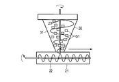
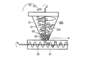
- FIG. 4C when pressure is applied, raw material compression proceeds in the lower part of the hopper 31, and the raw material G1 becomes the raw material G2. Since the gap between the hopper screw 32 and the granulating screw 22 is narrow, the raw material G2 is sent to the granulating device 20 without the retention of the raw material G2 (bridge phenomenon) at the outlet of the hopper 31. As shown in FIG.
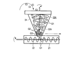
- the maximum portion of the raw material compression is the lowermost part of the hopper screw (immediately above the granulation screw), and the compressed raw material G3 is sent as it is by the granulation screw 22, so that the raw material conveyance speed is maintained. At this time, the temperature rises due to frictional heat, and unnecessary moisture evaporates.
- the raw material G1 is supplied from the supply device 80 to the hopper 31.
- the raw material G1 is in an uncompressed state and is bulky. Therefore, the raw material G1 is fed while applying pressure while rotating the hopper screw 32A. In this process, the raw material G1 is crushed and a twist, swivel, rotation, and frictional force are applied.
- the laminate layer LA and the paper component layer LB are separated, and are released from the laminate layer LA as a thermoplastic resin piece, and the fibrous cellulose F is released from the paper component layer LB. Furthermore, twisting, turning, rotation, and frictional force are applied to the fibrous cellulose F.
- FIG. 5A the raw material G1 is supplied from the supply device 80 to the hopper 31.
- the raw material G1 is in an uncompressed state and is bulky. Therefore, the raw material G1 is fed while applying pressure while rotating the hopper screw 32A. In this process, the raw material G1 is crushed and a twist, swivel, rotation, and frictional force are
- the raw material compression under the hopper 31 proceeds.
- the amount of the raw material G1 may not be large, and the raw materials G2 and G3 are smoothly fed to the granulation screw 22 with a small amount, and the fibrous cellulose F and the thermoplastic resin piece are kneaded and solidified.
- the maximum portion of the raw material compression is the lowermost portion of the hopper screw 32 ⁇ / b> A, and the compressed raw material G ⁇ b> 2 is easily accumulated in the hopper 31.
- the raw material conveying force to the granulator 20 decreases. As shown in FIG.
- the compression device 30 has a granulation amount of 200 kg / hour.
- the compression device 30A has a granulation amount of 20 to 30 kg / hour. Therefore, the configuration in which the tip of the hopper screw 32 is inserted into the barrel 21 increases the production efficiency by several to ten times.
- the raw material to be introduced is a soft and light material and has a high frictional resistance
- the hopper 31 outlet must be narrow in the granulation process
- the pushing pressure becomes weak and the bridge phenomenon occurs at the hopper 31 outlet. Occurs and the supply capacity of the raw material is extremely reduced.
- the hopper screw 32 is extended to a position where it does not hit the granulation screw 22, so that the pressing pressure is maintained and the smoothness to the granulation apparatus 20 is maintained. Supplying raw materials can improve production capacity.
- FIG. 3 shows the structure of the cellulose-containing resin pellet P produced in this way. That is, the fibrous cellulose F contained in the cellulose-containing resin pellet P is separated from the paper component layer LB of the laminated paper L.
- the resin component adhering to the fibrous cellulose F contained in the cellulose-containing resin pellet P is a synthetic resin component constituting the laminate layer LA of the laminate paper L.
- the cellulose-containing resin pellet P is a granular body formed by condensing the fibrous cellulose F, and the resin component is constrained to at least a part of the granular body.
- the fibrous cellulose F having a relatively long fiber length constituting the pellet P is formed by crushing a laminated paper L called a so-called used paper pack and then separating it from the paper component layer. .
- the cellulose-containing resin pellet P is composed of fibrous cellulose F having a fine fiber size and a relatively long fiber length. That is, the fibrous cellulose F has a fiber length of 500 to 1500 ⁇ m, and maintains a curved, bent or twisted form inside the cellulose-containing resin pellet P, and the synthetic cellulose F Dispersed and blended in the resin composition.
- the laminated paper L is regenerated to produce the cellulose-containing resin pellets P, the paper component layer LB and the laminated layer LA constituting the laminated paper L are not separated from each other.
- Cellulose-containing resin pellets P can be formed directly from the laminated paper L.
- the particle size of the cellulose-containing resin pellet P is not particularly limited, but it is a particle size that does not cause any obstacle in the injection molding process or the extrusion molding process in the subsequent molding process. It is desirable.
- the synthetic resin composition finally obtained is composed only of cellulose-containing resin pellets P, and therefore the basic raw materials are practically the same as the constituent materials of the paper pack.
- the strength was measured using a synthetic resin composition produced by the cellulose-containing resin pellet P according to the present embodiment and a wood pellet-containing resin pellet having a fiber length of less than 500 ⁇ m as a comparative example.
- the mass ratio between the paper component and the resin component was 50% each.
- Charpy impact strength of the cellulose-containing resin pellet P is 0.48 MPa / m 2, and has a sufficient strength than 0.28 ⁇ 0.34MPa / m 2 wood flour-containing resin pellets.
- the cellulose-containing resin pellet P is 32.1 MPa / m 2 , which is sufficiently stronger than 30.3 MPa / m 2 of the resin pellet containing wood flour.
- the fibrous cellulose F has a water absorption of about 0.8%, has conductivity, and has an antistatic function. This function is exhibited when the mass ratio of the fibrous cellulose F is 30% or more. In addition, when the mass ratio of the fibrous cellulose F exceeds 70%, solidification becomes difficult and the form cannot be maintained as pellets.
- the synthetic resin component may contain a synthetic resin or an additive other than the synthetic resin forming the laminate layer LA constituting the paper pack.
- the properties of the formed cellulose-containing resin pellets P and the synthetic resin composition can be controlled by synthetic resins and additives other than the synthetic resin forming the laminate layer LA.
- by mixing pumice or paint, cellulose-containing resin pellets P and synthetic resin compositions having a function suitable for the application can be generated.
- the laminate paper L is temporarily separated from the laminate paper L by a dry method instead of wet, and the laminate component and the paper component are formed in an ideal shape without changing the initial mixing ratio of the laminate component and the paper component. Even when melted at a high temperature, the paper component does not carbonize, has no odor, and has a low water absorption compared to wood, and has a high mechanical strength and an inexpensive long fiber mixed resin composition. .
- FIG. 6 is an explanatory view showing a cellulose-containing resin pellet manufacturing apparatus 110 according to the second embodiment of the present invention.
- the cellulose-containing resin pellet manufacturing apparatus 110 regenerates the laminated paper L to produce the cellulose-containing resin pellet P, the paper component layer LB and the laminated layer LA constituting the laminated paper L are separated from each other. Without this, the cellulose-containing resin pellets P are formed directly from the laminated paper L.
- the cellulose-containing resin pellet manufacturing apparatus (mixer) 110 includes a fixed processing tank (mixed layer) 101.
- a rotating shaft 103 is inserted into the bottom 102 of the fixed processing tank 101 and is driven to rotate by an electric motor 104.
- a blade 105 is provided on the rotating shaft 103.
- the blade 105 includes three rotary blades 105-1, 105-2, and 105-3.
- reference numeral 131 denotes a cut laminated paper L.
- the laminated paper L is put into the fixed processing tank 101, and the blade 105 is rotated at a high speed to generate frictional heat on the laminated paper L.
- the laminated resin layer LA of the laminated paper L and the paper component layer are generated by the frictional heat.
- a thermal expansion change is generated between the LB and at least a part of the interface between the laminate resin layer LA of the laminated paper L and the paper component layer LB is peeled and separated using the thermal expansion change.
- the laminate layer LA is released as a thermoplastic resin piece, and the fibrous cellulose F is released from the paper component layer LB.
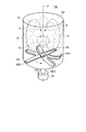
- the blade 105 in the fixed treatment tank 101 rotates at 1300 rpm / 110 kW or more and 1500 rpm / 110 kW (E in FIG. 6), and generates a rising or descending airflow (G in FIG. 6) with a wind speed of 10 to 30 m / s.
- twisting, twisting, turning, rotation, and frictional force are applied to the fibrous cellulose F contained in the paper component layer LB.
- the fine cellulose F is condensed into a dense state, and the fibrous cellulose F and the thermoplastic resin piece are kneaded and solidified. Thereafter, the condensate is appropriately granulated and deformed into granules having an appropriate size.
- the blade 105 does not have a function of cutting or cutting the laminated paper L, but has a function of rotating while pressing the laminated paper L.
- the laminated synthetic resin material constituting the laminated layer LA separated from the laminated paper L is melted by the frictional heat and rotational force generated by the rotation of the blade 105, and the viscosity of the molten synthetic resin material is melted.
- the paper component layer LB is broken, and the fibrous cellulose F separated from the paper component layer LB by the breaking action is subjected to twisting action, folding, folding, or rotation / swirl action, and is densely integrated with each other.
- the molten synthetic resin component is infiltrated into at least a part of the fiber lump and acts as an adhesive as a whole. To be constrained.
- the paper component layer LB in the laminated paper L is not finely cut, but the kneading force, that is, the viscosity of the resin constituting the laminated layer LA is used by the blade 105 of the cellulose-containing resin pellet manufacturing apparatus 100.
- the paper component layer LB is decomposed. For this reason, the fibrous cellulose F having a relatively long fiber length (500-1500 ⁇ m) that has not been cut is twisted, bent, folded, pulled, pressed, swung / rotated, entangled in an appropriate direction with an appropriate external force.
- the separated fibrous cellulose F is formed into a densely aggregated state in a bundled state, and a pellet-like lump having a minute particle size in harmony with the synthetic resin component contained therein Transform into a body. Furthermore, the pellet of the state which the said resin affixed is formed in the surface of the said pellet-like lump, or at least one part of the inside.
- the laminate paper L is temporarily separated from the laminate paper L by a dry method instead of wet, and the laminate component and the paper component are formed in an ideal shape without changing the initial mixing ratio of the laminate component and the paper component. Even when melted at a high temperature, the paper component does not carbonize, has no odor, and has a low water absorption compared to wood, and has a high mechanical strength and an inexpensive long fiber mixed resin composition. .
- FIG. 3 is an electron micrograph obtained by partially enlarging a cellulose-containing resin pellet P formed from a used milk pack according to the method for producing the cellulose-containing resin pellet P according to the present invention. That is, FIG. 3 is an electron micrograph of a part of cellulose-containing resin pellets P, which is a fluid produced by the method for producing cellulose-containing resin pellets according to the present invention, taken from the surface.
- the ultrafine fibrous cellulose F is twisted and elongated, and is intertwined with each other and arranged in a concentrated manner.
- the polyethylene resin separated from the laminate layer is It is shown as the part which appears black, and it understands that they are melt
- this structure proves that the resin component is a principle that the fibrous cellulose F is further entangled in a complicated manner so that the fibrous cellulose F is made thinner and longer and folded into the resin.
- the fact that the interval between the fibrous cellulose F is narrower is the basis that the fibrous cellulose F is narrower than the paper and the strength is increased.
- the mixed state of the cellulose-containing resin pellet P will be described.
- the fibrous cellulose F in a paper state is twisted and elongated.
- the resin is a black portion, it is dissolved without any gap between the fibrous cellulose F, and the mechanism in which the fibrous cellulose F is further entangled in the resin component so as to be further thinned and folded into the resin to improve the strength. It is as it is.
- the resin laminated in the fixed processing tank 101 is frictionally heated by the blade 105, and the laminated paper L is temporarily separated into a polyethylene component and a paper component, but the paper component is then twisted and thinned by the rotational force. Then, since the polyethylene component melts and penetrates into the fibrous cellulose F or covers the fibrous cellulose F, uniform mixing is established.
- the fiber length can be secured because the pellet is not subjected to rotational force in the conventional method.
- the fibrous cellulose F does not become thin as in the case of the present invention. That is, it is clear that a mixing method using the cellulose-containing resin pellet manufacturing apparatus 110 is advantageous for reducing the surface area of the fibers and mixing with the resin. In the conventional method, since the resin is not evenly adhered to the fiber, an air layer is generated inside, which causes a quality problem.
- Cellulose-containing resin pellets in which paper fibers are uniformly mixed without shortening the paper and the manufacturing method thereof, and the synthetic resin composition having increased strength and the manufacturing method thereof, and cellulose-containing resin pellet manufacturing A device is obtained.
Landscapes
- Engineering & Computer Science (AREA)
- Mechanical Engineering (AREA)
- Environmental & Geological Engineering (AREA)
- Processing And Handling Of Plastics And Other Materials For Molding In General (AREA)
- Separation, Recovery Or Treatment Of Waste Materials Containing Plastics (AREA)
- Compositions Of Macromolecular Compounds (AREA)
Abstract
紙と樹脂フィルムとが積層したラミネート材料を分解・混練して固形化するセルロース含有樹脂ペレット製造装置において、上部開口部から前記ラミネート材料が投入され、下部開口部から排出するホッパ31と、ホッパ31に同軸的に配置され、上部開口部から下部開口部へ向けて前記ラミネート材料を送り出すと共に、先端が前記ホッパの下部開口部から外部へ突出したホッパスクリュ32と、ホッパ31の下部開口部に接続された筒状のバレル21と、バレル21内に同軸的に収容されると共に、ホッパスクリュ32の直下に配置され、前記ラミネート材料を混練して送り出す造粒スクリュ22を備え、効率良くペレット化する。
Description
本発明は、セルロース含有樹脂ペレット及びその製造方法並びに当該セルロース含有樹脂ペレットを原料とした合成樹脂組成物及びその製造方法、セルロース含有樹脂ペレット製造装置に関し、例えば、ラミネート紙等を再生処理する方法の一環として実施されるものに関する。
ガラス繊維や炭素繊維、セルロース繊維等をプラスチック材料中に分散させることで、強度を高める技術が知られている(例えば、日本国特許公開公報2011-116838号)。特にセルロース繊維を用いたものは、使用済の紙類等を有効利用できることから、今後の利用が期待される。
一方、ラミネート紙(ラミネート材料)の再生利用については様々な技術が知られている。ラミネート紙とは、例えば、クラフト紙のような紙成分層(繊維状セルロースを含有)の一面或いは両面に、例えば、ポリエチレン系合成樹脂成分等からなる薄膜層で構成されたラミネート樹脂層が貼り合わされている加工紙材料である。ラミネート紙は、何も加工されていない通常のクラフト紙よりも強度、耐水性、防湿性に優れている。
このため、ラミネート紙は、牛乳やジュース、ヨーグルト等の飲料や、醤油、麺つゆ、ソース等の調味料等を含む各種の食品類を収容する為の紙容器として広範囲に実用されている。包装用紙、牛乳パック、お茶・コーヒー、カップ麺の容器、ブリックタイプの飲料パックなどがその用途例である。プラスチック、鉄鋼、金属関係の業種などの分野でも、様々な場面で当該ラミネート紙はよく使用されている。なお、「ラミネート紙」は、「ポリラミ」、「PEラミ」、「PEクラフト」、「クラフトラミ」などと呼ばれることもある。
ラミネート紙のクラフト紙は、その主成分がバージンパルプで、500μm~1500μm程度の長繊維が繊維の中で50%以上の割合を占める繊維状セルロースにより形成されている。一方、ラミネート樹脂の樹脂成分は、低臭で食品用の安全な低密度ポリエチレン等の流動性が高い樹脂が一般的である。例えば、ポリエチレンなどの樹脂、つまり、マテリアルリサイクルが最も良い原料が使われている。しかしながら、ラミネート紙を構成するそれぞれの構成成分は、マテリアルリサイクルに優れた原料ではあるが、複合材であるがためにリサイクルが難しく、又はコストがかかり採算が取れない。
ラミネート紙を再生処理する為の技術としては、これまで、種々の方法が提案されてきている。例えば、一般的な再生技術とは別に当該ラミネート紙を元の状態に戻す方法、或いは、紙成分と樹脂成分とを分離する方法、或いは、当該分離技術以外に、当該ラミネート紙に分離処理技術をしようせず、当該ラミネート紙を細かく裁断して、そのまま樹脂と紙との複合材として成形する方法等が知られている。当該方法の一具体的としては、例えば、当該ラミネート紙を裁断又は微細に裁断して得られた樹脂成分が付着したままのラミネート紙を熱溶融させ成形する技術がある。
上述したラミネート紙の再生処理においては、次のような問題があった。すなわち、ラミネート紙を分解した後、成形する場合、プラスチックの一般的な成形方法が採用される。しかし、ラミネート紙の紙成分を細かくしなくては紙(繊維状セルロース)の毛羽立ちが強く樹脂との混合を阻害する。このため紙成分は可能な限り細かくしなくてはならない。
その為、繊維セルロースは、全てが短くなり粉末となり、紙素材としての強度が低下する。したがって、紙素材としての特性(強度)は悪化する。また、これらの技術に近い別の混合方法に於いては、紙成分を裁断する方法がとられるが、当該紙を細かくする方法のみでは、当該紙成分に附帯する樹脂成分だけで再生紙素材は得られないので、別途、樹脂成分をバインダーとして添加して紙との複合樹脂組成物を形成させる方法も知られている。
ラミネート紙の一種であるミルクカートン(牛乳パック)については、回収されてトイレットペーパー等に再生されている。これらの再生工程では、当該ミルクカートンを展開した上で、パルパーという大きな洗濯機のような構造をしている機械に投入し、液状の離解液とする。離解液は当該機械底部のフィルターを通り異物を取り除き、水分を除去した後に固める。その際、ミルクカートンの両面に塗布されたポリエチレン樹脂も除去されるが、ポリエチレン樹脂はストレーナに詰ってしまうため、装置の掃除を繰り返す必要がある。このため、能率が下がることから敬遠されており、当該ラミネート紙の再生コストが上がり、焼却処分に回される物も多い。近年では、当該焼却するなら、当該ラミネート紙のポリエチレンは燃焼カロリーも高く有害な燃焼ガスも発生しないため燃料として再生する技術開発も注目されている。
一方では、当該ラミネート紙のマテリアルリサイクルとしては、湿式分離において当該紙パックの紙成分層とラミネート層からなる樹脂成分層とに分ける方法が確立されている。しかし、分離された樹脂成分紙成分は完全な分離が難しくリサイクル単一性分材の単一成分は物性が安定しない。そのため同一成分を多量に混入させて品質を向上させている。
この他、ラミネート紙の紙成分と樹脂成分とを分離することなくマテリアルリサイクルを行う技術として、ラミネート紙を裁断し微細化して熱溶融させて成形品を作る方法がある。しかしながら、樹脂成形においては射出成形方法もあり、当該樹脂を噴射ノズルから紙成分をも含めて、吐出させなくてはならなく、その為に、紙成分の微細化を行うことが必要であるものの、裁断の際、熱が発生し樹脂成分が溶融して裁断を妨げるため微細化が難しい。その他の技術としてはラミネート紙を裁断して熱硬化性樹脂で硬化させて成形物を作る方法も開示されている。更に、ラミネート紙はラミネートしている樹脂と紙成分が一定の割合で構成されており配合条件が担保されているにも関わらず分離して樹脂成分と紙成分の各々のリサイクル方法がとられている。
また、使用済の紙パックの再生処理方法が開示されている(例えば、日本国特許公開公報2003-235579号)。この再生処理方法では、使用済の紙パックの紙成分層の表面部に形成されている、例えば、ポリエチレン系合成樹脂層からなるラミネート層に細かい切り筋(切れ目)を形成した紙パックを、所定の水溶液に浸漬して、ラミネート層を剥離させ、紙成分層のみを再生紙素材として適宜の成型装置に掛けて成型する方法が開示されており、その再生紙素材の一部に当該ポリエチレン系合成樹脂が付着している紙シートを得る方法が開示されている。つまり、係る従来技術では、当該紙パックの紙成分層をそのままの形で再利用しようとするものであるが、当該紙パックに切り筋や切れ目を入れる工程が必要であり、コストの高騰につながる欠点が存在している。
また、当該使用済み紙パックを粉砕して粉状にした粉状紙パックに更に樹脂原料を追加して溶融混練し、できた再生合成樹脂を押し出し機等から押し出して、ペレット化する方法が開示されている(例えば、日本国特許公開公報2000-43037号)。当該紙パックを粉状態にまで粉砕処理する必要があり、同様にコスト高とならざるを得ないという欠点が存在している。
そこで本発明は、再生処理が困難で大量に発生する紙パック等のラミネート紙を、簡易な技術構成でありながら、成形樹脂へ混入して成形材として使用できる強度が出せるセルロース含有樹脂ペレット及びセルロース含有樹脂ペレット製造方法、セルロース含有樹脂ペレットを用いた合成樹脂組成物及び合成樹脂組成物の製造方法、セルロース含有樹脂ペレット製造装置を提供することを目的とする。
さらに、静電気が起きにくい帯電防止特性を有し、かつ、木質調の外観風合いを有する商品価値の高い合成樹脂組成物の製造に適したペレットを容易に、かつ、効率的に然も安価に製造出来る技術を提供するものであると同時に、当該ペレットを使用した、強度があり、静電気が起きにくい帯電防止特性を有し、かつ、木質調の外観風合いを有する商品価値の高い、合成樹脂組成物並びに、当該合成樹脂組成物を効率よく、容易に且つ安価に製造する為の方法・装置を提供することを目的としている。
本発明は、繊維状セルロースが集密的に凝縮されて形成された粒状体であって、当該粒状体の少なくとも一部に樹脂成分が拘束されていることを特徴とするセルロース含有樹脂ペレットである。
本発明は、当該ラミネート紙を再生処理して、前記された当該セルロース含有樹脂ペレットを生成するに際し、当該ラミネート紙を構成する当該紙成分層とラミネート層とを相互に分離することなく、当該ラミネート紙から直接的に当該セルロース含有樹脂ペレットを形成させることを特徴とするセルロース含有樹脂ペレットの製造方法である。
本発明は、当該セルロース含有樹脂ペレットを内蔵する合成樹脂組成物である。
本発明は、当該ペレットを含む合成樹脂組成物であり、並びに当該ペレットを、所要の重量比を以って再生合成樹脂に混合し、撹拌混合装置に於いて、所要の回転数(rpm)の下で、例えば、切断刃部を持たない回転刃の形状を持ったブレード部が配備されている撹拌混合装置内で、適宜の温度条件下で混合処理し、その後成形加工処理を行う合成樹脂組成物の製造方法である。
即ち、本発明に於ける当該基本的な技術構成は、従来のラミネート紙の再生テクニックとは全く異なる技術構成を持ったラミネート紙の再処理方法を提供するものであり、その基本的技術構成に於ける従来の技術構成との明確な技術上の相違は、当該ラミネート紙に於ける当該紙成分層を微裁断するのではなく、当該混合機のブレードによりラミネート層を構成する樹脂の練込力つまり粘性を利用して当該紙成分層を分解させる。切断されていない、比較的長い繊維長を有するセルロース系の紙繊維で構成される分離された個々の長繊維に適宜の外力で、適宜の方向に捻じれ、折り曲げ、折り畳み、引張、旋回・回転、絡合、摩擦力等作用を付与することによって、分離された当該セルロース系の微細な、繊度が極めて細い長繊維状のそれぞれの繊維或いは複数の相互に隣接した配置されている長繊維群が纏まった状態で集密的集合状態に形成され、それに含まれる合成樹脂成分と調和して微少な粒径を持ったペレット状塊状体に変身することになり、更に、当該ペレット状塊状体の表面或いはその内部の少なくとも一部に、当該樹脂が貼着した状態のペレットが形成されるものである。
本発明によれば、上記した問題点を実質的に解消させることが可能であることは勿論のこと、処理操作工程が簡易化されることにより、生産効率の向上と製造設備費や製造コスト等が低減されるので、全体的なコストが安価でありながら、当該合成樹脂組成物としての強度があり、静電気が起きにくい帯電防止特性を有し、かつ、木質調の外観風合いを有すると共に、軽量化で、然も釘を打ち込むことが可能な商品価値の高い、合成樹脂組成物並びにその製造方法を提供することが可能である。つまり、当該ラミネート紙を分離する工程を特別に設けず、当該紙成分層と当該ラミネート層を構成していた樹脂成分が相互に分散及び均一配合され、紙成分の高配合条件においても流動性があるペレット及びその製造方法が提供され、更には、当該ペレットを内蔵する高品質の及合成樹脂組成物とその製造方法が得られる。
更に、本発明に於いては、ラミネート紙を構成する樹脂成分と紙成分から、当該樹脂成分を当該紙成分に含浸混合させることでラミネート紙の完全なマテリアル利用が可能となり、含浸混合されたペレットは単体成形を可能にして樹脂成分を増加する場合も相溶効果がある。係るラミネート紙を湿式ではなく乾式にてラミネートと紙を一時的に分離させラミネート成分と紙成分を当初配合比を変えること無くラミネート成分と紙成分を理想的な形状にして混合し高温での溶融に対しても紙成分が炭化することなく、臭気がなく、木材に比べて吸水率が少ない機械強度に富んだ安価な長繊維混入樹脂組成物を提供する。
以下、添付図面にもとづき、本発明の実施形態に係るセルロース含有樹脂ペレット(成形樹脂混入用ペレット)P及びその製造方法、更には当該セルロース含有樹脂ペレットPを原料とした合成樹脂組成物及びその製造方法、セルロース含有樹脂ペレット製造装置10について詳細に説明する。なお、ここでの樹脂は、熱可塑性樹脂であり、例えばオレフィン系樹脂である。オレフィン系樹脂としては、ポリエチレンやポリプロピレンが一般的に用いられている。
図1は、本発明の実施形態に係るセルロース含有樹脂ペレット製造装置10及び合成樹脂組成物製造装置(再生合成樹脂組成物)50を示している。図2はセルロース含有樹脂ペレットPの材料となるラミネート紙Lを模式的に示す説明図、図3はセルロース含有樹脂ペレットPを電子顕微鏡写真で示す説明図である。
ラミネート紙Lは、図2に示すように、主な繊維長が500~1500μmの繊維状セルロース(微細繊維)Fが層状に形成された紙成分層LBと当該紙成分層LBの表裏の一面或いは双方の面に、適宜の合成樹脂成分が層状或いは薄膜状に形成されたラミネート層LAとから構成されるものである。なお、このようなラミネート紙Lにおける繊維成分のうち質量比で50%以上が500~1500μmの繊維状セルロースFである。ラミネート紙Lは、所定の目的の下に使用され回収されて来た使用済み、かつ、再生処理の対象となっている。なお、ミルクカートン等に用いられるラミネート紙Lは一般的に繊維状セルロースの繊維長が500~1500μmのものを多く含んでいる。また、繊維状セルロースFの質量はラミネート紙Lの質量の30~70%程度で、樹脂の質量はその残部である70~30%である。
ラミネート紙Lは、牛乳やジュース、ヨーグルト容器として使用されたものであり、再生処理対象として用いられるものである。なお、使用済みのラミネート紙のみでなく、新規にラミネート紙を工場内で製造し所定の型に従って裁断処理する際に、裁断くずとして大量に発生するいわゆる端材を用いてもよい。また、プラスチック、鉄鋼、金属関係の業種などの分野の様々な環境で使用されたものであっても良い。この他、目的の如何に関わらず、経済的に且つ効率的に再生処理することが可能である形態であれば広く用いることができる。
セルロース含有樹脂ペレット製造装置10は、造粒装置20と、この造粒装置20の上部に設けられた圧縮装置30と、この圧縮装置30に所定の長さに切断されたラミネート紙Lを投入する供給装置80とを備えている。
造粒装置20は、軸方向を水平方向にして配置された筒状のバレル21と、このバレル21内に同軸的に配置された造粒スクリュ22と、この造粒スクリュ22を回転駆動する電動機23とを備えている。
圧縮装置30は、切断されたラミネート紙Lが投入されるホッパ31と、このホッパ31に同軸的に配置され、投入されたラミネート紙Lを圧縮するホッパスクリュ32と、このホッパスクリュ32を回転駆動する電動機33とを備えている。なお、ホッパスクリュ32の先端は、バレル21内の造粒スクリュ22に干渉しない位置まで挿入されている。さらに詳細に説明すると、ホッパスクリュ32の先端は、バレル21の内壁面の内側であって、かつ、造粒スクリュ22の外径よりも外側に位置している。
合成樹脂組成物製造装置50は、造粒装置20の先端に配置され、セルロース含有樹脂ペレットPを押し出す押出成型機60と、押し出されたセルロース含有樹脂ペレットPの形状を形成する金型装置70とを備えている。なお、金型装置70はタイルやブロック材等の合成樹脂組成物を形成するためのキャビティが形成されている。
このように構成されたセルロース含有樹脂ペレット製造装置10及び合成樹脂組成物製造装置50では、次のようにしてセルロース含有樹脂ペレットPの生成及び合成樹脂組成物の製造を行う。なお、ラミネート紙Lを適当な長さ・大きさに切断したものを原料G1とする。また、原料G2は原料G1より圧縮されて高密度の状態、原料G3は原料G2よりさらに圧縮された高密度の状態を示している。
図4Aに示すように、供給装置80から原料G1をホッパ31に供給する。図4Bに示すように、原料G1は圧縮されていない状態であり嵩張るため、ホッパスクリュ32を回転させながら、圧力をかけて送る。図4Cに示すように、圧力がかかると、ホッパ31下部において原料圧縮が進み原料G1が原料G2となる。ホッパスクリュ32と造粒スクリュ22の間隔が狭いため、ホッパ31の出口に原料G2の滞留(ブリッジ現象)が起こらずに、原料G2が造粒装置20へ送られる。図4Dに示すように原料圧縮の最大箇所はホッパスクリュ最下部であり(造粒スクリュ直上)、さらに圧縮された原料G3がそのまま造粒スクリュ22によって送られるため、原料搬送スピードが維持される。この時、摩擦熱により温度上昇し、不要な水分が蒸発する。
比較例として先端がバレル21内に到達していないホッパスクリュ32Aを用いた圧縮装置30Aについて説明する。
図5Aに示すように、供給装置80から原料G1をホッパ31に供給する。図5Bに示すように、原料G1は圧縮されていない状態であり嵩張るため、ホッパスクリュ32Aを回転させながら、圧力をかけて送る。この過程において、原料G1が破砕され、ねじれ・旋回・回転・摩擦力が加えられる。これにより、ラミネート層LAと紙成分層LBとが分離し、ラミネート層LAからは熱可塑性樹脂片として遊離し、紙成分層LBからは繊維状セルロースFが遊離する。さらに、繊維状セルロースFはねじれ・旋回・回転・摩擦力が加えられる。図5Cに示すように、圧力がかかると、ホッパ31下部の原料圧縮が進む。運転開始直後は原料G1が多くないこともあり原料G2,G3は少量ながらも造粒スクリュ22に順調に送られ、繊維状セルロースFと熱可塑性樹脂片とを混練して固化する。図5Dに示すように、原料圧縮の最大箇所はホッパスクリュ32Aの最下部であり、圧縮された原料G2がホッパ31内に溜まりやすくなる。原料滞留が進むと、造粒装置20への原料搬送力が低下する。図5Eに示すように、原料G2が柔らかく、かつ嵩張る性質で摩擦力もあることからホッパ31下部で原料が詰まる(ブリッジ現象)が発生する。ホッパスクリュ32Aの空転が起こり始める。図5Fに示すように、ホッパスクリュ32Aの下部の押込み圧低下と原料性からくる強い復元力でホッパスクリュ32Aが空転する。ホッパスクリュ32Aの停止時にはホッパ31の下部で原料G2,G3が圧縮された状態で停止する。
本実施形態に係るホッパスクリュ32を用いた圧縮装置30と、比較例に係るホッパスクリュ32Aを用いた圧縮装置30Aとの生産量を同一条件で比較すると、圧縮装置30は造粒量200kg/時間であるのに対し、圧縮装置30Aは造粒量20~30kg/時間である。したがって、ホッパスクリュ32の先端がバレル21内に挿入されている構成は数倍から10倍程度に製造効率が高まる。
このように投入する原料が柔らかく軽い材質でかつ摩擦抵抗が強いこと、ホッパ31出口が造粒工程上狭くならざるを得なく、通常のホッパスクリュ32Aでは押込み圧力の弱くなるホッパ31出口でブリッジ現象が発生し、原料の供給能力が極端に低下する。これを防ぐため、このようにセルロース含有樹脂ペレット製造装置10では、ホッパスクリュ32を造粒スクリュ22に当たらない位置まで延長させることで、押込み圧力を維持した形で造粒装置20への円滑な原料供給を行い、生産能力を向上させることができる。
図3は、このようにして製造されたセルロース含有樹脂ペレットPの構成を示している。すなわち、セルロース含有樹脂ペレットPに含まれている当該繊維状セルロースFは、ラミネート紙Lの紙成分層LBから分離されたものである。セルロース含有樹脂ペレットPに含まれている繊維状セルロースFに付着している樹脂成分は、ラミネート紙Lのラミネート層LAを構成する合成樹脂成分である。
セルロース含有樹脂ペレットPは、図3に示すように、繊維状セルロースFが集密的に凝縮されて形成された粒状体であって、粒状体の少なくとも一部に樹脂成分が拘束されている。ところで、ペレットPを構成する比較的長い繊維長を持った繊維状セルロースFは、所謂使用済み紙パックと称されるラミネート紙Lを破砕した後に紙成分層から分離されて形成されたものである。
一方、セルロース含有樹脂ペレットPは、微細な繊度を有する比較的繊維長の長い繊維状セルロースFから構成されたものである。即ち、繊維状セルロースFは、500~1500μmの繊維長を有し、且つそれらが、セルロース含有樹脂ペレットPの内部に於いて湾曲状、折り曲げ状或いはねじれ状等の形態を保持して、当該合成樹脂組成物内に分散配合されている。
また、ラミネート紙Lを再生処理して、前記された当該セルロース含有樹脂ペレットPを生成するに際し、当該ラミネート紙Lを構成する当該紙成分層LBとラミネート層LAとを相互に分離することなく、当該ラミネート紙Lから直接的にセルロース含有樹脂ペレットPを形成させることができる。
更に、セルロース含有樹脂ペレットPの粒径は、特に限定されるものではないが、後工程の成型工程に於いて射出成型工程或いは押し出し成型工程に於いて、障害が発生しないような粒径であることが望ましい。
また、最終的に得られる合成樹脂組成物はセルロース含有樹脂ペレットPのみで構成されるものであり、従って、その基本的原材料は、当該紙パックの構成素材と実施的に同一である。
本実施形態に係るセルロース含有樹脂ペレットPによって生成された合成樹脂組成物と、比較例として繊維長が500μm未満である木粉入り樹脂ペレットを板状にして強度を測定した。なお、紙成分と樹脂成分との質量比は50%ずつとした。セルロース含有樹脂ペレットPのシャルピー衝撃強度は、0.48MPa/m2であり、木粉入り樹脂ペレットの0.28~0.34MPa/m2よりも十分な強度を有している。曲げ強度についても、セルロース含有樹脂ペレットPが、32.1MPa/m2であり、木粉入り樹脂ペレットの30.3MPa/m2よりも十分な強度を有している。これらは、繊維状セルロースFが一定の長さを有していることから、強度が増加したと考えられる。なお、繊維長が1500μmを超えると固化が困難になり、ペレットとして形態を保てない。
また、繊維状セルロースFは吸水率が0.8%程度であり、導電性を有し、静電気防止機能を有している。この機能は、繊維状セルロースFの質量比が30%以上の範囲で発揮される。なお、繊維状セルロースFの質量比が70%を超えると、固化が困難になり、ペレットとして形態を保てない。
なお、必要に応じて、当該合成樹脂成分として、当該紙パックを構成している当該ラミネート層LAを形成している合成樹脂以外の合成樹脂や添加剤が含まれている場合もある。ラミネート層LAを形成している合成樹脂以外の合成樹脂や添加剤により、形成されたセルロース含有樹脂ペレットPや合成樹脂組成物の特質を制御することができる。この他、軽石や塗料等を混合することで、用途に適した機能を有するセルロース含有樹脂ペレットPや合成樹脂組成物を生成できる。
なお、押出成型機60による押出成型においては、流動性の高い物質が成形品の外側に集中する傾向がある。このため、繊維状セルロースFは成形物内側に集まり、表面は滑らかな樹脂成分のみが露出する。このとき、合成樹脂組成物の樹脂成分が70%を超えると、一般的な接着剤(酢酸ビニル接着剤)で接合することが困難となり、溶融接着を用いることになる。しかしながら、合成樹脂組成物に繊維状セルロースFが30%以上含まれていると、紙やすりで表面を僅かに削るだけで繊維状セルロースFが露出し、一般的な接着剤(酢酸ビニル接着剤)で接合することが可能となる。すなわち、溶融接着以外の接合を行うことも可能となり、応用範囲を広げることができる。
本実施形態においては、ラミネート紙Lを湿式ではなく、乾式にてラミネート紙Lを一時的に分離させラミネート成分と紙成分を当初配合比を変えること無くラミネート成分と紙成分を理想的な形状にして混合し高温での溶融に対しても紙成分が炭化することなく、臭気がなく、木材に比べて吸水率が少ない機械強度に富んだ安価な長繊維混入樹脂組成物が得られるものである。
図6は、本発明の第2実施形態に係るセルロース含有樹脂ペレット製造装置110を示す説明図である。セルロース含有樹脂ペレット製造装置110は、ラミネート紙Lを再生処理して、当該セルロース含有樹脂ペレットPを生成するに際し、当該ラミネート紙Lを構成する当該紙成分層LBとラミネート層LAとを相互に分離することなく、当該ラミネート紙Lから直接的に当該セルロース含有樹脂ペレットPを形成させる。
セルロース含有樹脂ペレット製造装置(混合機)110は、固定処理槽(混合層)101を備えている。この固定処理槽101の底部102には、回転軸103が挿通され、電動機104によって回転駆動される。回転軸103にはブレード105が設けられている。ブレード105は、3枚の回転刃105-1,105-2,105-3から構成されている。なお、図中131は切断されたラミネート紙Lを示している。
ラミネート紙Lを、固定処理槽101内に投入し、ブレード105を高速回転させることにより、ラミネート紙Lに摩擦熱を発生させると共に、摩擦熱によりラミネート紙Lのラミネート樹脂層LAと当該紙成分層LBとの間に熱膨張変化を発生させ、熱膨張変化を利用して、当該ラミネート紙Lのラミネート樹脂層LAと当該紙成分層LBとの界面の少なくとも一部を剥離分離させる。ラミネート層LAからは熱可塑性樹脂片として遊離し、紙成分層LBからは繊維状セルロースFが遊離する。その際に、固定処理槽101内のブレード105は1300rpm/110kw以上1500rpm/110kWで回転し(図6中E)、風速10~30m/sの上昇又は下降気流(図6中G)を発生させて、当該紙成分層LB内に含まれる繊維状セルロースFにねじれ・捻り・旋回・回転・摩擦力が加えられる。繊状セルロースFを集密的な状態に凝縮させ、繊維状セルロースFと熱可塑性樹脂片とを混練して固化する。その後、当該凝縮体を適宜に造粒処理して適宜の大きさに形成された粒状体に変形させる。
ブレード105は、ラミネート紙Lを切断或いは裁断する機能は有せず、ラミネート紙Lを押圧しながら回転する機能を有するものを使用する。
一方、ブレード105の回転により発生する摩擦熱と回転力により、ラミネート紙Lから分離されたラミネート層LAを構成する当該ラミネート合成樹脂材が溶融されると共に、当該溶融された当該合成樹脂材料の粘性により、紙成分層LBが破壊され、破壊作用により紙成分層LBより分離された繊維状セルロースFが、捻じれ作用や、折り畳み、折り曲げ、或いは回転・旋回作用を受けて、集密的に相互に絡合し、凝縮された繊維塊状体に構成されると同時に、当該繊維塊状体の少なくとも一部には、当該溶融されたラミネート合成樹脂成分が、侵入し、全体的に接着材的な作用を呈するように拘束させる。
本実施形態においては、ラミネート紙Lに於ける当該紙成分層LBを微裁断せず、セルロース含有樹脂ペレット製造装置100のブレード105によりラミネート層LAを構成する樹脂の練込力つまり粘性を利用して当該紙成分層LBを分解させる。このため、切断されていない比較的長い繊維長(500~1500μm)を有する繊維状セルロースFに適宜の外力で、適宜の方向に、捻じれ、折り曲げ、折り畳み、引張、押圧、旋回・回転、絡合等作用を付与することによって、分離された繊維状セルロースFが纏まった状態で集密的集合状態に形成され、それに含まれる合成樹脂成分と調和して微少な粒径を持ったペレット状塊状体に変身する。更に、当該ペレット状塊状体の表面或いはその内部の少なくとも一部に、当該樹脂が貼着した状態のペレットが形成されるものである。
本実施形態においては、ラミネート紙Lを湿式ではなく、乾式にてラミネート紙Lを一時的に分離させラミネート成分と紙成分を当初配合比を変えること無くラミネート成分と紙成分を理想的な形状にして混合し高温での溶融に対しても紙成分が炭化することなく、臭気がなく、木材に比べて吸水率が少ない機械強度に富んだ安価な長繊維混入樹脂組成物が得られるものである。
この工程では、当該ラミネート樹脂層LAから分離された当該合成樹脂材のみでなく、必要に応じて、別途、同一の合成樹脂か異なる合成樹脂を併用追加することも可能である。
此処で、本発明により得られた当該セルロース含有樹脂ペレットPの具体例について、図3を参照しながら説明する。図3は、使用済みの牛乳パックを本発明に係る当該セルロース含有樹脂ペレットPの製造方法に従って形成されたセルロース含有樹脂ペレットPの部分拡大による電子顕微鏡写真である。即ち、図3は、本発明に係る当該セルロース含有樹脂ペレットの製造方法に従って形成された造流体であるセルロース含有樹脂ペレットPの一部を該表面から撮影した電子顕微鏡写真であって、図3から明らかな通り、極細の繊維状セルロースFはねじれを起こし細く長くなっており、且つ相互に絡合して集密状に固まって配置されていると同時に、当該ラミネート層から分離されたポリエチレン樹脂は黒く映る部分として示されており、それらは繊維状セルロースF間に隙間なく溶け込んでいることが理解される。
係る構造は、既に説明した通り、樹脂成分が繊維状セルロースFを更に細く長くして樹脂内に折り重なるように複雑に絡み合い強度向上となる原理となっていることを証明するものである。また繊維状セルロースF間の間隔が狭くなっていることは紙の状態より繊維状セルロースF間が狭くなり強度を増していることとの根拠となるものである。
次にセルロース含有樹脂ペレットPの混合状態について説明する。図3に示すように、紙の状態の繊維状セルロースFはねじれを起こし細く長くなっている。樹脂は黒く映る部分であるが、繊維状セルロースF間に隙間なく溶け込んでおり、樹脂成分中に当該繊維状セルロースFが更に細く長くして樹脂内に折り重なるように複雑に絡み合い強度向上となるメカニズムとなっている通りである。
固定処理槽101内でラミネートされた樹脂がブレード105により摩擦熱がかかり一時的に、ラミネート紙Lはポリエチレン分と紙成分に分離されるものの、紙成分はその後回転力で繊維がねじれて細くなり、そこに、ポリエチレン分が溶融して繊維状セルロースFに浸透又は繊維状セルロースFを覆うことから均一な混合が成り立つことになる。
一方、セルロース含有樹脂ペレット製造装置110を使用しない従来の混合方法で構成された同じペレットと比較すると、当該従来の方法にペレットでは、繊維に回転力が加わっていないため繊維長は確保できたとしても当該繊維状セルロースFが本発明の場合のように細くなることはない。つまり、当該繊維の表面積を少なくして樹脂と混合させるにはセルロース含有樹脂ペレット製造装置110を使用した混合方法が有利であることは明らかである。又、従来の方法によるものは、樹脂の状態も繊維に均一に付着していないため内部に空気層が発生することになり、品質上の問題が発生する。
以上、本実施形態を説明したが、上述の実施形態は、例として提示したものであり、実施形態の範囲を限定することは意図していない。この新規な実施形態は、その他の様々な形態で実施されることが可能であり、要旨を逸脱しない範囲で、種々の省略、置換え、変更を行うことができる。これら実施形態やその変形は、発明の範囲や要旨に含まれるとともに、特許請求の範囲に記載された発明とその均等の範囲に含まれる。
樹脂と紙とが混在した古紙から、紙の繊維を短くことなく均一に混合したセルロース含有樹脂ペレット及びその製造方法、また強度を増加させた合成樹脂組成物及びその製造方法、セルロース含有樹脂ペレット製造装置が得られる。
Claims (12)
- 熱可塑性樹脂と、
この熱可塑性樹脂内に分散され、500~1500μmの長さを有する繊維状セルロースとを備えていることを特徴とするセルロース含有樹脂ペレット。 - 前記熱可塑性樹脂は、30~70質量%であることを特徴とする請求項1に記載のセルロース含有樹脂ペレット。
- 前記繊維状セルロースは、30~70質量%であることを特徴とする請求項1に記載のセルロース含有樹脂ペレット。
- 前記繊維状セルロースは、500~1500μmの長さを有する繊維状セルロースを含む紙材から遊離されたものであり、
前記熱可塑性樹脂は、前記紙材に積層された熱可塑性樹脂シートから生成されたものであることを特徴とする請求項1に記載のセルロース含有樹脂ペレット。 - 500~1500μmの長さを有する繊維状セルロースを含む紙材と、熱可塑性樹脂シートとが積層されたラミネート材からセルロース含有樹脂ペレットを製造するセルロース含有樹脂ペレット製造方法において、
前記ラミネート材を破砕し、
破砕された前記ラミネート材に、ねじれ・旋回・回転・摩擦力の少なくとも一つを加えて、前記紙材と前記熱可塑性樹脂シートを分離すると共に、前記紙材から前記繊維状セルロースを遊離し、かつ、前記熱可塑性樹脂シートから熱可塑性樹脂片を生成し、
前記繊維状セルロースと前記熱可塑性樹脂片とを混練して固化することを特徴とするセルロース含有樹脂ペレット製造方法。 - 500~1500μmの長さを有する繊維状セルロースを含む紙材と、熱可塑性樹脂シートとが積層されたラミネート材からセルロース含有樹脂ペレットを製造するセルロース含有樹脂ペレット製造方法において、
前記ラミネート材をブレードを有する混合槽内に投入し、
前記ブレードを回転させて、前記ラミネート材に摩擦力を加えて、前記紙材と前記熱可塑性樹脂シートを分離すると共に、前記紙材から前記繊維状セルロースを遊離し、かつ、前記熱可塑性樹脂シートから熱可塑性樹脂片を生成し、
前記繊維状セルロースと前記熱可塑性樹脂片とを混練して固化することを特徴とするセルロース含有樹脂ペレット製造方法。 - 前記ブレードは1300rpm/110kw以上1500rpm/110kWで回転し、風速10~30m/sの上昇又は下降気流を発生させて、前記紙材に含まれる繊維状セルロース群に捻りを加えることを特徴とする請求項6に記載のセルロース含有樹脂ペレット製造方法。
- 前記ブレードは、前記ラミネート材を押圧しながら回転する機能を有することを特徴とする請求項6に記載のセルロース含有樹脂ペレット製造方法。
- 請求項1に記載されたセルロース含有樹脂ペレットが溶融されて、固化されて形成されたことを特徴とする合成樹脂組成物。
- 請求項1に記載されたセルロース含有樹脂ペレットを溶融し、
型内に押し出し、
冷却して固化することを特徴とする合成樹脂組成物製造方法。 - 紙成分を含む紙と樹脂成分を含む樹脂フィルムとが積層したラミネート材料を分解・混練してペレット状に固化された合成樹脂組成物を生成する合成樹脂組成物製造方法において、
前記ラミネート材料をブレードを有する混合槽内に投入し、
前記樹脂成分とは異なる添加樹脂成分を前記混合槽内に投入し、
前記ブレードを回転させて、前記紙成分と前記樹脂フィルムとを積層状態を維持したまま摩擦熱を発生させて前記紙成分と前記樹脂フィルムとを剥離させ、
前記紙成分と前記樹脂成分と前記添加樹脂成分とを混練し、集密的な状態に凝縮させたペレット状とすることを特徴とする合成樹脂組成物の製造方法。 - 紙と樹脂フィルムとが積層したラミネート材料を分解・混練して固形化するセルロース含有樹脂ペレット製造装置において、
上部開口部から前記ラミネート材料が投入され、下部開口部から排出するホッパと、
このホッパに同軸的に配置され、上部開口部から下部開口部へ向けて前記ラミネート材料を送り出すと共に、先端が前記ホッパの下部開口部から外部へ突出したホッパスクリュと、
前記ホッパの下部開口部に接続された筒状のバレルと、
前記バレル内に同軸的に収容されると共に、前記ホッパスクリュの直下に配置され、前記ラミネート材料を混練して送り出す造粒スクリュとを備えていることを特徴とするセルロース含有樹脂ペレット製造装置。
Priority Applications (2)
| Application Number | Priority Date | Filing Date | Title |
|---|---|---|---|
| JP2017523743A JPWO2016199942A1 (ja) | 2015-06-12 | 2016-06-13 | セルロース含有樹脂ペレット、セルロース含有樹脂ペレット製造方法、合成樹脂組成物、合成樹脂組成物の製造方法及びセルロース含有樹脂ペレット製造装置 |
| CN201680034299.XA CN107708950A (zh) | 2015-06-12 | 2016-06-13 | 含纤维素的树脂粒料、含纤维素的树脂粒料制法、合成树脂组合物、合成树脂组合物的制法及含纤维素的树脂粒料制造装置 |
Applications Claiming Priority (2)
| Application Number | Priority Date | Filing Date | Title |
|---|---|---|---|
| JP2015-118835 | 2015-06-12 | ||
| JP2015118835 | 2015-06-12 |
Publications (1)
| Publication Number | Publication Date |
|---|---|
| WO2016199942A1 true WO2016199942A1 (ja) | 2016-12-15 |
Family
ID=57503930
Family Applications (1)
| Application Number | Title | Priority Date | Filing Date |
|---|---|---|---|
| PCT/JP2016/067590 WO2016199942A1 (ja) | 2015-06-12 | 2016-06-13 | セルロース含有樹脂ペレット、セルロース含有樹脂ペレット製造方法、合成樹脂組成物、合成樹脂組成物の製造方法及びセルロース含有樹脂ペレット製造装置 |
Country Status (3)
| Country | Link |
|---|---|
| JP (1) | JPWO2016199942A1 (ja) |
| CN (1) | CN107708950A (ja) |
| WO (1) | WO2016199942A1 (ja) |
Cited By (5)
| Publication number | Priority date | Publication date | Assignee | Title |
|---|---|---|---|---|
| WO2019038869A1 (ja) * | 2017-08-23 | 2019-02-28 | 古河電気工業株式会社 | セルロース繊維分散ポリエチレン樹脂複合材、これを用いた成形体及びペレット、これらの製造方法、並びにセルロース繊維付着ポリエチレン薄膜片のリサイクル方法 |
| WO2019038868A1 (ja) * | 2017-08-23 | 2019-02-28 | 古河電気工業株式会社 | セルロース繊維分散ポリエチレン樹脂複合材、これを用いた成形体及びペレット、これらの製造方法、並びにセルロース繊維付着ポリエチレン薄膜片のリサイクル方法 |
| US11390723B2 (en) | 2016-12-05 | 2022-07-19 | Furukawa Electric Co., Ltd. | Cellulose-aluminum-dispersing polyethylene resin composite material, pellet and formed body using same, and production method therefor |
| US11466145B2 (en) | 2017-08-23 | 2022-10-11 | Furukawa Electric Co., Ltd. | Cellulose-fiber-dispersing polyolefin resin composite material |
| US11597826B2 (en) | 2017-08-23 | 2023-03-07 | Furukawa Electric Co., Ltd. | Cellulose-fiber-dispersing polyolefin resin composite material, pellet and formed body using same, and production method for cellulose-fiber-dispersing polyolefin resin composite material |
Citations (7)
| Publication number | Priority date | Publication date | Assignee | Title |
|---|---|---|---|---|
| JPH0780909A (ja) * | 1993-09-16 | 1995-03-28 | Kawaguchi Gosei Kk | 牛乳用紙パック及びフィルムラミネート紙の再利用方法 |
| JP2000052339A (ja) * | 1998-08-11 | 2000-02-22 | Trust:Kk | 成形用組成物の製造方法およびそれに用いる古紙ペレット |
| JP2001310326A (ja) * | 2000-04-28 | 2001-11-06 | Mitsubishi Paper Mills Ltd | プラスチックフィルムラミネート紙細断物、その製造方法及び該細断物を配合した合成樹脂組成物 |
| JP2006347031A (ja) * | 2005-06-16 | 2006-12-28 | Toa Kagaku Kogyo Kk | アルミ箔ラミネート紙を原料とする樹脂化ペレット製造方法 |
| JP2007260941A (ja) * | 2006-03-27 | 2007-10-11 | Hokuetsu Paper Mills Ltd | 紙配合熱可塑性樹脂組成物の製造方法及びそれに用いる紙ペレット |
| JP2011116838A (ja) * | 2009-12-02 | 2011-06-16 | Mitsubishi Paper Mills Ltd | セルロース含有熱可塑性樹脂の製造方法、セルロース含有熱可塑性樹脂およびその成形体 |
| JP2011190322A (ja) * | 2010-03-12 | 2011-09-29 | Mitsubishi Paper Mills Ltd | セルロース含有熱可塑性樹脂の製造方法、セルロース含有熱可塑性樹脂およびその成形体 |
-
2016
- 2016-06-13 CN CN201680034299.XA patent/CN107708950A/zh active Pending
- 2016-06-13 JP JP2017523743A patent/JPWO2016199942A1/ja active Pending
- 2016-06-13 WO PCT/JP2016/067590 patent/WO2016199942A1/ja active Application Filing
Patent Citations (7)
| Publication number | Priority date | Publication date | Assignee | Title |
|---|---|---|---|---|
| JPH0780909A (ja) * | 1993-09-16 | 1995-03-28 | Kawaguchi Gosei Kk | 牛乳用紙パック及びフィルムラミネート紙の再利用方法 |
| JP2000052339A (ja) * | 1998-08-11 | 2000-02-22 | Trust:Kk | 成形用組成物の製造方法およびそれに用いる古紙ペレット |
| JP2001310326A (ja) * | 2000-04-28 | 2001-11-06 | Mitsubishi Paper Mills Ltd | プラスチックフィルムラミネート紙細断物、その製造方法及び該細断物を配合した合成樹脂組成物 |
| JP2006347031A (ja) * | 2005-06-16 | 2006-12-28 | Toa Kagaku Kogyo Kk | アルミ箔ラミネート紙を原料とする樹脂化ペレット製造方法 |
| JP2007260941A (ja) * | 2006-03-27 | 2007-10-11 | Hokuetsu Paper Mills Ltd | 紙配合熱可塑性樹脂組成物の製造方法及びそれに用いる紙ペレット |
| JP2011116838A (ja) * | 2009-12-02 | 2011-06-16 | Mitsubishi Paper Mills Ltd | セルロース含有熱可塑性樹脂の製造方法、セルロース含有熱可塑性樹脂およびその成形体 |
| JP2011190322A (ja) * | 2010-03-12 | 2011-09-29 | Mitsubishi Paper Mills Ltd | セルロース含有熱可塑性樹脂の製造方法、セルロース含有熱可塑性樹脂およびその成形体 |
Cited By (9)
| Publication number | Priority date | Publication date | Assignee | Title |
|---|---|---|---|---|
| US11390723B2 (en) | 2016-12-05 | 2022-07-19 | Furukawa Electric Co., Ltd. | Cellulose-aluminum-dispersing polyethylene resin composite material, pellet and formed body using same, and production method therefor |
| WO2019038869A1 (ja) * | 2017-08-23 | 2019-02-28 | 古河電気工業株式会社 | セルロース繊維分散ポリエチレン樹脂複合材、これを用いた成形体及びペレット、これらの製造方法、並びにセルロース繊維付着ポリエチレン薄膜片のリサイクル方法 |
| WO2019038868A1 (ja) * | 2017-08-23 | 2019-02-28 | 古河電気工業株式会社 | セルロース繊維分散ポリエチレン樹脂複合材、これを用いた成形体及びペレット、これらの製造方法、並びにセルロース繊維付着ポリエチレン薄膜片のリサイクル方法 |
| JPWO2019038868A1 (ja) * | 2017-08-23 | 2020-08-06 | 古河電気工業株式会社 | セルロース繊維分散ポリエチレン樹脂複合材、これを用いた成形体及びペレット、これらの製造方法、並びにセルロース繊維付着ポリエチレン薄膜片のリサイクル方法 |
| JPWO2019038869A1 (ja) * | 2017-08-23 | 2020-08-06 | 古河電気工業株式会社 | セルロース繊維分散ポリエチレン樹脂複合材、これを用いた成形体及びペレット、これらの製造方法、並びにセルロース繊維付着ポリエチレン薄膜片のリサイクル方法 |
| US11390724B2 (en) | 2017-08-23 | 2022-07-19 | Furukawa Electric Co., Ltd. | Cellulose-fiber dispersion polyethylene resin composite material, formed body and pellet using same, production method therefor, and recycling method for cellulose-fiber adhesion polyethylene thin film piece |
| US11466145B2 (en) | 2017-08-23 | 2022-10-11 | Furukawa Electric Co., Ltd. | Cellulose-fiber-dispersing polyolefin resin composite material |
| US11597826B2 (en) | 2017-08-23 | 2023-03-07 | Furukawa Electric Co., Ltd. | Cellulose-fiber-dispersing polyolefin resin composite material, pellet and formed body using same, and production method for cellulose-fiber-dispersing polyolefin resin composite material |
| US11667763B2 (en) | 2017-08-23 | 2023-06-06 | Furukawa Electric Co., Ltd. | Cellulose-fiber dispersion polyethylene resin composite material, formed body and pellet using same, production method therefor, and recycling method for cellulose-fiber adhesion polyethylene thin film piece |
Also Published As
| Publication number | Publication date |
|---|---|
| JPWO2016199942A1 (ja) | 2018-05-17 |
| CN107708950A (zh) | 2018-02-16 |
Similar Documents
| Publication | Publication Date | Title |
|---|---|---|
| WO2016199942A1 (ja) | セルロース含有樹脂ペレット、セルロース含有樹脂ペレット製造方法、合成樹脂組成物、合成樹脂組成物の製造方法及びセルロース含有樹脂ペレット製造装置 | |
| JPS6257491B2 (ja) | ||
| EP3159127B1 (en) | Method for manufacturing a plastic composition comprising thermoplastic and thermoset material | |
| JP4680000B2 (ja) | 紙含有樹脂組成物及びその成形品並びにそれらの製造方法 | |
| KR940011143B1 (ko) | 압출성형 제품의 제조방법 및 장치 | |
| JP2017145392A (ja) | セルロース繊維分散ポリエチレン樹脂複合材、それを用いた成形体及びペレット、並びに、セルロース繊維付着ポリエチレン薄膜片のリサイクル方法 | |
| JP6284672B2 (ja) | セルロース繊維分散ポリエチレン樹脂複合材の製造方法、及びセルロース繊維付着ポリエチレン薄膜片のリサイクル方法 | |
| JP2017145393A (ja) | セルロース繊維分散ポリエチレン樹脂複合材、それを用いた成形体及びペレット、並びに、セルロース繊維分散ポリエチレン樹脂複合材の製造方法 | |
| CN108137826A (zh) | 用于生产木质纤维素塑料复合材料的方法 | |
| MX2014004455A (es) | Dispositivo para procesar material plastico. | |
| JP2006347031A (ja) | アルミ箔ラミネート紙を原料とする樹脂化ペレット製造方法 | |
| CN109789451A (zh) | 由复合膜生产致密材料的方法、生产设备和用途 | |
| WO1999042230A1 (fr) | Procede de production d'article moule en matieres plastiques fondues melangees de differents types | |
| JP2008238626A (ja) | 熱可塑性樹脂組成物の製造方法 | |
| JP2004017502A (ja) | ペレット製造装置およびペレット製造方法 | |
| JP2010138337A (ja) | 木粉を含有する成形品の製造方法ならびに成形品 | |
| US9145496B2 (en) | Composite product, a method for manufacturing a composite product and its use, a material component and a final product | |
| KR100856943B1 (ko) | 펠릿 및 그 제조방법 및 그 성형품 | |
| JP4695119B2 (ja) | 木質系コンパウンドの製造方法及び木質系コンパウンド | |
| JP2019199009A (ja) | 竹粉複合樹脂の製造方法、竹粉樹脂混合溶融体の製造方法、竹粉樹脂混合溶融体及び竹粉複合樹脂 | |
| JP4633585B2 (ja) | 樹脂含有積層体の製造方法 | |
| JP6914541B2 (ja) | 熱可塑性樹脂組成物の成形機、および製造方法 | |
| US20110109007A1 (en) | Recycled post-industrial waste for plastic industrial commercial and consumer products | |
| JP2015203111A (ja) | ガラスウール複合熱可塑性樹脂組成物及びその製造法、成形物。 | |
| JP3810982B2 (ja) | プラスチックフィルムラミネート紙細断物、その製造方法及び該細断物を配合した合成樹脂組成物 |
Legal Events
| Date | Code | Title | Description |
|---|---|---|---|
| 121 | Ep: the epo has been informed by wipo that ep was designated in this application |
Ref document number: 16807645 Country of ref document: EP Kind code of ref document: A1 |
|
| ENP | Entry into the national phase |
Ref document number: 2017523743 Country of ref document: JP Kind code of ref document: A |
|
| NENP | Non-entry into the national phase |
Ref country code: DE |
|
| 122 | Ep: pct application non-entry in european phase |
Ref document number: 16807645 Country of ref document: EP Kind code of ref document: A1 |