WO2016199721A1 - 伸縮ブームの取付構造 - Google Patents
伸縮ブームの取付構造 Download PDFInfo
- Publication number
- WO2016199721A1 WO2016199721A1 PCT/JP2016/066762 JP2016066762W WO2016199721A1 WO 2016199721 A1 WO2016199721 A1 WO 2016199721A1 JP 2016066762 W JP2016066762 W JP 2016066762W WO 2016199721 A1 WO2016199721 A1 WO 2016199721A1
- Authority
- WO
- WIPO (PCT)
- Prior art keywords
- boom
- base
- bracket
- width
- telescopic boom
- Prior art date
- Legal status (The legal status is an assumption and is not a legal conclusion. Google has not performed a legal analysis and makes no representation as to the accuracy of the status listed.)
- Ceased
Links
Images



Classifications
-
- B—PERFORMING OPERATIONS; TRANSPORTING
- B66—HOISTING; LIFTING; HAULING
- B66C—CRANES; LOAD-ENGAGING ELEMENTS OR DEVICES FOR CRANES, CAPSTANS, WINCHES, OR TACKLES
- B66C23/00—Cranes comprising essentially a beam, boom, or triangular structure acting as a cantilever and mounted for translatory of swinging movements in vertical or horizontal planes or a combination of such movements, e.g. jib-cranes, derricks, tower cranes
- B66C23/18—Cranes comprising essentially a beam, boom, or triangular structure acting as a cantilever and mounted for translatory of swinging movements in vertical or horizontal planes or a combination of such movements, e.g. jib-cranes, derricks, tower cranes specially adapted for use in particular purposes
- B66C23/36—Cranes comprising essentially a beam, boom, or triangular structure acting as a cantilever and mounted for translatory of swinging movements in vertical or horizontal planes or a combination of such movements, e.g. jib-cranes, derricks, tower cranes specially adapted for use in particular purposes mounted on road or rail vehicles; Manually-movable jib-cranes for use in workshops; Floating cranes
- B66C23/42—Cranes comprising essentially a beam, boom, or triangular structure acting as a cantilever and mounted for translatory of swinging movements in vertical or horizontal planes or a combination of such movements, e.g. jib-cranes, derricks, tower cranes specially adapted for use in particular purposes mounted on road or rail vehicles; Manually-movable jib-cranes for use in workshops; Floating cranes with jibs of adjustable configuration, e.g. foldable
-
- B—PERFORMING OPERATIONS; TRANSPORTING
- B66—HOISTING; LIFTING; HAULING
- B66C—CRANES; LOAD-ENGAGING ELEMENTS OR DEVICES FOR CRANES, CAPSTANS, WINCHES, OR TACKLES
- B66C23/00—Cranes comprising essentially a beam, boom, or triangular structure acting as a cantilever and mounted for translatory of swinging movements in vertical or horizontal planes or a combination of such movements, e.g. jib-cranes, derricks, tower cranes
- B66C23/62—Constructional features or details
- B66C23/82—Luffing gear
Definitions
- the present invention relates to a mounting structure for a telescopic boom that attaches the telescopic boom to a swing post so that it can be raised and lowered.
- a telescopic boom mounting structure in which a telescopic boom that can be telescopically mounted by nesting a plurality of intermediate booms nested inside a base boom on a pivot post that is pivotably provided on the base of a crane is known. (See Patent Document 1).
- the telescopic boom mounting structure is provided with a pair of holding plate portions opposed to the turning post, and the rear portion of the base boom of the telescopic boom is mounted between the holding plate portions via a shaft member, and the base boom is mounted by the shaft member.
- the swing post can be raised and lowered.
- the gap between the side wall portion of the base boom and the side wall portion of the intermediate boom is set narrow, and the base boom or the like is distorted in the side wall portion due to heat of welding or the like.
- the width of the base boom can be increased.
- the width of the base boom is set according to the width between the holding plates of the swivel post, try to increase the width of the base boom. Then, it was necessary to change to a swivel post having a larger width between the pair of holding plate portions of the swivel post.
- An object of the present invention is to provide a telescopic boom mounting structure capable of preventing interference between a base boom and an intermediate boom without changing an existing turning post.
- the present invention is a telescopic boom mounting structure in which a rear portion of a base boom of a telescopic boom of a work machine is held by a bracket, and the base boom is mounted to the swing post by the bracket so as to be raised and lowered.
- the bracket has a pair of contact plate portions joined to both side wall portions of the rear portion of the base boom, Each of the contact plate portions has a base piece that can be held up and down between a pair of opposing holding portions of the swivel post,
- the width of the bracket other than the base piece is set larger than the width of the bracket of the base piece.
- the width of the base boom can be increased without changing the turning post, and interference between the base boom and the intermediate boom can be prevented.
- FIG. 1 shows a truck crane (crane) 10 as a working machine to which a telescopic boom mounting structure is applied.
- the truck crane 10 includes a main frame 14 that extends in the front-rear direction and has a front wheel 11 and first and second rear wheels 12 and 13, a turning post 20 that is turnable on the main frame 14,
- the telescopic boom 100 provided at the upper part of the swing post 20, the hoisting cylinder 15 for lifting the telescopic boom 100, and the position of the swing post (position with respect to the front-rear direction) on both sides of the main frame 14.
- a pair of provided outrigger devices 30 (only one of them is shown), a cabin 16 provided on the main frame 14 on the front side of the turning post 20, a loading platform 17 provided on the rear side of the turning post 20, and the like are provided. .
- the swivel post 20 has a pair of opposing holding plate portions (holding portions) 21 (only one of them is shown) that holds the telescopic boom 100 so that it can be raised and lowered.
- a winch and a speed reducer (not shown) are arranged in the turning post 20, and a wire (not shown) for suspending a suspended load is wound up or fed out.
- the telescopic boom 100 includes a base boom 110, intermediate booms 111 and 112, and a tip boom 113, and is configured by being nested in the base boom 110 from the outside to the inside in this order.
- the telescopic boom 100 is expanded and contracted by an expansion cylinder (not shown).
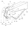
- FIGS. 2 and 2A show the mounting structure of the telescopic boom 100 for mounting the telescopic boom 100 to the turning post.
- a bracket 120 is attached to the rear portion of the base boom 110, and the base boom 110 is attached to the swing post 20 via the bracket 120 so as to be raised and lowered.
- the bracket 120 includes a pair of contact plate portions 130 and 130 that are in contact with both side wall portions 110 ⁇ / b> A and 110 ⁇ / b> B of the base boom 110, and a rear upper portion of the pair of contact plate portions 130 and 130. And an end plate 140 which is disposed between the rear ends and connects the contact plate portions 130.
- each abutment plate portion 130 is provided at a welding region portion 131 including a welding region welded to the side wall portion 110 ⁇ / b> A of the base boom 110 and a rear portion of the welding region portion 131 and the base boom 110. And a base piece 132 protruding rearward from the rear end position.
- the boundary between the base piece 132 and the welding region 131 is a stepped portion 133.
- the width W2 between the base piece 132,132 of the bracket 120 is set smaller than the width W1 between the welding area
- the welding area 131 of the bracket 120 has a V-shaped protruding piece 131A protruding downward from the lower surface 110C of the base boom 110.
- a shaft hole 129 is formed at the lowermost portion of the protruding piece 131A, and reinforcing flanges 127 and 128 are formed along ridgelines (edges) 122A and 122B of the protruding piece 131A.
- an opening 126 for ensuring welding strength is formed at the center of the welding region 131.
- the base piece 132 is fixed with a shaft hole 124 for mounting the telescopic boom 100 between the holding plate portions 21 of the swivel post 20, and one end of the telescopic cylinder of the telescopic boom 100.
- a shaft hole 125 for mounting a shaft member (not shown) is formed.
- the base piece 132, 132 of the bracket 120 is inserted between the holding plate parts 21, 21 of the turning post 20, and the turning post is inserted into the shaft holes 124, 124 of the base piece 132, 132.
- the bracket 120 is attached to the pivot post 20 by inserting the 20 shaft members 150.
- the shaft hole 129 of one welding region portion 131 of the bracket 120 and the shaft of a protruding piece (not shown) of the other welding region portion 131 are used.
- a shaft member (not shown) is attached to the hole. Accordingly, the telescopic boom 100 is raised and lowered around the shaft member 150 by the expansion and contraction operation of the hoisting cylinder 15.
- the width W1 between the contact plate portions 130, 130 other than the base piece 132 is set to be larger than the width W2 between the base pieces 132, 132.
- the width in the lateral direction can be increased, and a gap between the side wall portions 110A and 110B of the base boom 110 and the side wall portion (not shown) of the intermediate boom 111 (see FIG. 1) can be increased.
- strain by heat, such as welding has generate
- the width W2 can be the same as the conventional width, the existing one can be used without changing the swivel post 20, and the existing shaft member 150 for undulation can be used.
- the lateral width of the base boom 110 can be increased, the lateral rigidity of the telescopic boom 100 can be increased.
- a multi-stage boom can be easily configured.
- FIG. 3 shows a bracket 200 of the second embodiment.
- the bracket 200 is disposed between a pair of contact plate portions 230 and 230 joined to both side wall portions 110A and 110B of the base boom 110, and between the rear upper portion and the rear end of the pair of contact plate portions 230 and 230. And an end plate 240 for connecting the contact plate portions 230.
- Each abutment plate portion 230 is provided at a rear portion of the welded portion (abutting portion) 231 welded to the side wall portion 110 ⁇ / b> A of the base boom 110 and the two welded region portions 231 and behind the rear end position of the base boom 110. And a base piece 232 protruding toward the bottom.
- the width W ⁇ b> 3 between the contact plate portions 230 and 230 of the boundary portion 233 gradually increases as going from the base piece 232 to the welding region portion 231.
- the bracket 200 is configured such that the stepped portion 133 of the bracket 120 shown in FIG. 2 is eliminated. By eliminating this stepped portion 133, stress concentration generated in the stepped portion 133 can be eliminated.
- the width W1 between the welded region portions 231 and 231 of the bracket 200 is set larger than the width W2 between the base pieces 232 and 232, as in the first embodiment.
- the width W1 between the welded regions 131, 131, 231, 231 of the brackets 120, 200 is set larger than the width W2 between the base pieces 132, 132, 232, 232. If the width W2 between the base pieces 132, 132, 232, 232 is set to be narrower than the width W1 between the welding region portions 131, 131, 231, 231, the turning post 20 while maintaining the lateral rigidity of the telescopic boom 100 is maintained. Can be reduced in size and weight.
Landscapes
- Engineering & Computer Science (AREA)
- Mechanical Engineering (AREA)
- Jib Cranes (AREA)
Abstract
ベースブームの幅を大きくすることができ、ベースブームと中間ブームとの干渉を防止する伸縮ブームの取付構造を提供する。クレーンの伸縮ブーム(100)のベースブーム(110)の後部をブラケット(120)によって保持するとともに、ブラケット(120)によってベースブーム(110)を旋回ポストに対して起伏可能に取り付ける伸縮ブームの取付構造であって、ブラケット(120)は、ベースブーム(110)の後部の両側壁部(110A),(110B)に接合される当接板部(130),(130)を備え、この各当接板部(130)は、旋回ポストの相対向した一対の保持部間に起伏可能に保持される一対の基部片(132),(132)を有し、基部片(132)以外の部分の当接板部(130),(130)間の幅(W1)を基部片(132),(132)間の幅(W2)より大きく設定した。
Description
この発明は、伸縮ブームを旋回ポストに起伏可能に取り付ける伸縮ブームの取付構造に関する。
従来から、クレーンの基台に旋回自在に設けた旋回ポストに、ベースブームの内側に複数の中間ブームを入れ子状に重ねて伸縮可能にした伸縮ブームを起伏可能に取り付ける伸縮ブームの取付構造が知られている(特許文献1参照)。
係る伸縮ブームの取付構造は、旋回ポストに相対向した一対の保持板部を設け、伸縮ブームのベースブームの後部を前記保持板部間に軸部材を介して取り付け、この軸部材によってベースブームを旋回ポストに対して起伏可能にしたものである。
ところで、伸縮ブームは、ベースブームの側壁部と中間ブームの側壁部との間の隙間が狭く設定され、ベースブームなどは溶接の熱などにより側壁部に歪が発生していることにより、中間ブームの側壁部とベースブームの側壁部とが干渉してしまう虞があった。この問題を解消するためには、ベースブームの幅を大きくすればよいが、ベースブームの幅は旋回ポストの保持板部間の幅に合わせて設定されているため、ベースブームの幅を大きくしようとすると、旋回ポストの一対の保持板部間の幅を大きくした旋回ポストに変更する必要があった。
この発明の目的は、既存の旋回ポストを変更せずにベースブームと中間ブームとの干渉を防止することのできる伸縮ブームの取付構造を提供することにある。
この発明は、作業機の伸縮ブームのベースブームの後部をブラケットによって保持するとともに、該ブラケットによって前記ベースブームを旋回ポストに対して起伏可能に取り付ける伸縮ブームの取付構造であって、
前記ブラケットは、前記ベースブームの後部の両側壁部に接合される一対の当接板部を有し、
この各当接板部は、前記旋回ポストの相対向した一対の保持部間に起伏可能に保持される基部片を有し、
この基部片におけるブラケットの幅に対して、この基部片以外のブラケットの幅を大きく設定したことを特徴とする。
前記ブラケットは、前記ベースブームの後部の両側壁部に接合される一対の当接板部を有し、
この各当接板部は、前記旋回ポストの相対向した一対の保持部間に起伏可能に保持される基部片を有し、
この基部片におけるブラケットの幅に対して、この基部片以外のブラケットの幅を大きく設定したことを特徴とする。
この発明によれば、旋回ポストを変更せずにベースブームの幅を大きくでき、ベースブームと中間ブームとの干渉を防止することができる。
以下、この発明に係る伸縮ブームの取付構造の実施の形態である実施例を図面に基づいて説明する。
[第1実施例]
図1は、伸縮ブームの取付構造を適用した作業機としてトラッククレーン(クレーン)10を示す。
図1は、伸縮ブームの取付構造を適用した作業機としてトラッククレーン(クレーン)10を示す。
このトラッククレーン10は、前後方向に延び且つ前輪11と第1,第2後輪12,13を設けたメインフレーム14と、このメインフレーム14の上に旋回可能に設けた旋回ポスト20と、この旋回ポスト20の上部に起伏可能に設けた伸縮ブーム100と、この伸縮ブーム100を起伏させる起伏用シリンダ15と、メインフレーム14の両サイド側に旋回ポストの位置(前後方向に対する位置)の近傍に設けた一対のアウトリガ装置30(一方のみを図示)と、メインフレーム14上に旋回ポスト20の前側に設けたキャビン16と、その旋回ポスト20の後側に設けた荷台17等とを備えている。
[旋回ポスト]
旋回ポスト20は、伸縮ブーム100を起伏可能に保持する相対向した一対の保持板部(保持部)21(片方のみ図示)を有している。また、旋回ポスト20内には、図示しないウインチ及び減速機が配置されており、吊荷を吊るワイヤ(図示せず)を巻き上げたり繰り出したりするようになっている。
[伸縮ブーム]
伸縮ブーム100は、ベースブーム110と中間ブーム111,112と先端ブーム113とを有し、この順序でベースブーム110内に外側から内側に入れ子式に組み合わされて構成されている。また、伸縮ブーム100は伸縮シリンダ(図示せず)によって伸縮するようになっている。
[旋回ポスト]
旋回ポスト20は、伸縮ブーム100を起伏可能に保持する相対向した一対の保持板部(保持部)21(片方のみ図示)を有している。また、旋回ポスト20内には、図示しないウインチ及び減速機が配置されており、吊荷を吊るワイヤ(図示せず)を巻き上げたり繰り出したりするようになっている。
[伸縮ブーム]
伸縮ブーム100は、ベースブーム110と中間ブーム111,112と先端ブーム113とを有し、この順序でベースブーム110内に外側から内側に入れ子式に組み合わされて構成されている。また、伸縮ブーム100は伸縮シリンダ(図示せず)によって伸縮するようになっている。
図2及び図2Aは、伸縮ブーム100を旋回ポストへ取り付けるための伸縮ブーム100の取付構造を示す。
図2及び図2Aに示すように、ベースブーム110の後部にブラケット120が取り付けられており、このブラケット120を介してベースブーム110が旋回ポスト20に対して起伏可能に取り付けられる。
[ブラケット]
ブラケット120は、図2に示すように、ベースブーム110の両側壁部110A,110Bに当接される一対の当接板部130,130と、この一対の当接板部130,130の後部上方から後端間に配置され、各当接板部130を接続する端板140とを有している。
[ブラケット]
ブラケット120は、図2に示すように、ベースブーム110の両側壁部110A,110Bに当接される一対の当接板部130,130と、この一対の当接板部130,130の後部上方から後端間に配置され、各当接板部130を接続する端板140とを有している。
各当接板部130は、図2に示すように、ベースブーム110の側壁部110Aに溶接された溶接領域を含む溶接領域部131と、この溶接領域部131の後部に設けられるとともにベースブーム110の後端の位置から後方へ突出した基部片132とを有している。この基部片132と溶接領域部131との境界は段部133となっている。
そして、ブラケット120の基部片132,132間の幅W2は、溶接領域部131,131間の幅W1より小さく設定されている。すなわち、基部片132以外の部分の当接板部130,130間の幅W1が基部片132,132間の幅W2より大きく設定されている。つまり、基部片132におけるブラケット120の幅W2に対して、この基部片132以外のブラケットの幅W1が大きく設定されている。
ブラケット120の溶接領域部131は、ベースブーム110の下面110Cから下方に突出したV字形の突出片131Aを有している。この突出片131Aの最下部に軸穴129が形成され、突出片131Aの稜線(縁部)122A,122Bに沿って補強用のフランジ127,128が形成されている。また、溶接領域部131の中央部には溶接強度を確保するための開口部126が形成されている。
基部片132には、図2Aに示すように、伸縮ブーム100を旋回ポスト20の保持板部21間に起伏自在に装着するための軸穴124と、伸縮ブーム100の伸縮用シリンダの一端を固定する軸部材(図示せず)を装着するための軸穴125とが形成されている。
ベースブーム110の側壁部110Bに接合される当接板部130も上記と同様な構成となっているので、その説明は省略する。
[伸縮ブームの取り付け]
伸縮ブーム100のベースブーム110の後部の両側壁部110A,110Bにブラケット120の溶接領域部131,131を溶接して、図2に示すように、ベースブーム110の後部にブラケット120を取り付ける。
[伸縮ブームの取り付け]
伸縮ブーム100のベースブーム110の後部の両側壁部110A,110Bにブラケット120の溶接領域部131,131を溶接して、図2に示すように、ベースブーム110の後部にブラケット120を取り付ける。
この後、図2Aに示すように、ブラケット120の基部片132,132を旋回ポスト20の保持板部21,21間に挿入させるとともに、その基部片132,132の軸穴124,124に旋回ポスト20の軸部材150を挿入させて、ブラケット120を旋回ポスト20に取り付ける。
また、起伏シリンダ15(図1参照)の一端部をブラケット120に連結するために、ブラケット120の一方の溶接領域部131の軸穴129と、他方の溶接領域部131の図示しない突出片の軸穴とに軸部材(図示せず)を装着する。これにより、伸縮ブーム100は起伏用シリンダ15の伸縮動作によって軸部材150を中心にして起伏することになる。
ところで、図2に示すように、基部片132以外の部分の当接板部130,130間の幅W1が基部片132,132間の幅W2より大きく設定されていることにより、ベースブーム110の横方向の幅を大きくとることができ、ベースブーム110の側壁部110A,110Bと中間ブーム111(図1参照)の側壁部(図示せず)との間の隙間を広くとることができる。このため、ベースブーム110及び中間ブーム111の側壁部に溶接等の熱による歪が発生していても、ベースブーム110と中間ブーム111との干渉を防止することができる。このため、厳密な歪取り処理を行わなくてもよいことになる。
しかも、幅W2を従来の幅と同一に設定することにより、旋回ポスト20を変更せずに既存のものが使用することができ、さらに、既存の起伏用の軸部材150を使用することができる。また、ベースブーム110の横方向の幅を大きくとることができることにより、伸縮ブーム100の横方向の剛性を高めることができる。しかも、ベースブーム110の横方向の幅を大きくとることができることにより、多段ブームを構成し易いものとなる。
なお、ブラケット120の各当接板部130は、1枚の板材からプレス成形により形成するが、2枚の板材を溶接して形成するようにしてもよい。
[第2実施例]
図3は第2実施例のブラケット200を示す。このブラケット200は、ベースブーム110の両側壁部110A,110Bに接合される一対の当接板部230,230と、この一対の当接板部230,230の後部上方から後端間に配置され、各当接板部230を接続する端板240とを有している。
[第2実施例]
図3は第2実施例のブラケット200を示す。このブラケット200は、ベースブーム110の両側壁部110A,110Bに接合される一対の当接板部230,230と、この一対の当接板部230,230の後部上方から後端間に配置され、各当接板部230を接続する端板240とを有している。
各当接板部230は、ベースブーム110の側壁部110Aに溶接される溶接領域部(当接部)231と、両溶接領域部231の後部に設けられるとともにベースブーム110の後端位置より後方へ突出した基部片232とを有している。
この基部片232と溶接領域部231との境界部233は、基部片232から溶接領域部231へいくにしたがって、境界部233の当接板部230,230間の幅W3が除々に大きくなるように設定されている。
すなわち、ブラケット200は、図2に示すブラケット120の段部133を無くすようにしたものであり、この段部133を無くすことにより、段部133に発生する応力集中を無くすることができる。
また、ブラケット200の溶接領域部231,231間の幅W1は、第1実施例と同様に、基部片232,232間の幅W2より大きく設定されている。
上記実施例は、いずれもブラケット120,200の溶接領域部131,131、231,231間の幅W1を基部片132,132、232,232間の幅W2より大きく設定しているが、逆に、基部片132,132、232,232間の幅W2を溶接領域部131,131、231,231間の幅W1より狭く設定すれば、伸縮ブーム100の横方向の剛性を保ったまま旋回ポスト20の小型軽量化を図ることができる。
また、上記実施例は、トラッククレーンの伸縮ブーム100に伸縮ブームの取付構造を適用した場合について説明したが、これに限らず、高所作業車等の他の作業機の伸縮ブームに適用してもよい。
上記実施例は、上述のものに限定されるものではない。また、この発明は、発明を逸脱しない範囲で設計変更することは可能である。
[関連出願への相互参照]
本出願は、2015年6月11日に日本国特許庁に出願された特願2015-118617号に基づいて優先権を主張し、その全ての開示は完全に本明細書で参照により組み込まれる。
本出願は、2015年6月11日に日本国特許庁に出願された特願2015-118617号に基づいて優先権を主張し、その全ての開示は完全に本明細書で参照により組み込まれる。
10 トラッククレーン(作業機)
20 旋回ポスト
21 保持板部(保持部)
100 伸縮ブーム
110 ベースブーム
110A 側壁部
110B 側壁部
111 中間ブーム
120 ブラケット
130 当接板部
131 溶接領域部
132 基部片
200 ブラケット
230 当接板部
231 溶接領域部(当接部)
232 基部片
20 旋回ポスト
21 保持板部(保持部)
100 伸縮ブーム
110 ベースブーム
110A 側壁部
110B 側壁部
111 中間ブーム
120 ブラケット
130 当接板部
131 溶接領域部
132 基部片
200 ブラケット
230 当接板部
231 溶接領域部(当接部)
232 基部片
Claims (2)
- 作業機の伸縮ブームのベースブームの後部をブラケットによって保持するとともに、該ブラケットによって前記ベースブームを旋回ポストに対して起伏可能に取り付ける伸縮ブームの取付構造であって、
前記ブラケットは、前記ベースブームの後部の両側壁部に接合される一対の当接板部を有し、
この各当接板部は、前記旋回ポストの相対向した一対の保持部間に起伏可能に保持される基部片を有し、
この基部片におけるブラケットの幅に対して、この基部片以外のブラケットの幅を大きく設定したことを特徴とする伸縮ブームの取付構造。 - 前記各当接板部は、前記ベースブームの側壁部に当接される当接部と、この当接部の後部に設けられた前記基部片とを有し、
前記基部片と当接部との境界部におけるブラケットの幅を、その基部片から当接部へいくにしたがって徐々に広くなるように設定したことを特徴とする請求項1に記載の伸縮ブームの取付構造。
Priority Applications (2)
| Application Number | Priority Date | Filing Date | Title |
|---|---|---|---|
| KR1020177032309A KR101942213B1 (ko) | 2015-06-11 | 2016-06-06 | 신축 붐의 장착 구조 |
| CN201680029045.9A CN107735351B (zh) | 2015-06-11 | 2016-06-06 | 伸缩起重臂的安装构造 |
Applications Claiming Priority (2)
| Application Number | Priority Date | Filing Date | Title |
|---|---|---|---|
| JP2015118617A JP6531505B2 (ja) | 2015-06-11 | 2015-06-11 | 伸縮ブームの取付構造 |
| JP2015-118617 | 2015-06-11 |
Publications (1)
| Publication Number | Publication Date |
|---|---|
| WO2016199721A1 true WO2016199721A1 (ja) | 2016-12-15 |
Family
ID=57503384
Family Applications (1)
| Application Number | Title | Priority Date | Filing Date |
|---|---|---|---|
| PCT/JP2016/066762 Ceased WO2016199721A1 (ja) | 2015-06-11 | 2016-06-06 | 伸縮ブームの取付構造 |
Country Status (4)
| Country | Link |
|---|---|
| JP (1) | JP6531505B2 (ja) |
| KR (1) | KR101942213B1 (ja) |
| CN (1) | CN107735351B (ja) |
| WO (1) | WO2016199721A1 (ja) |
Families Citing this family (1)
| Publication number | Priority date | Publication date | Assignee | Title |
|---|---|---|---|---|
| JP7463865B2 (ja) * | 2020-06-08 | 2024-04-09 | 株式会社タダノ | ブーム |
Citations (5)
| Publication number | Priority date | Publication date | Assignee | Title |
|---|---|---|---|---|
| US5158189A (en) * | 1991-12-12 | 1992-10-27 | Watson Brothers Industries, Inc. | Boom support system |
| US5515654A (en) * | 1994-11-02 | 1996-05-14 | Anderson; Edward E. | Telescopic boom apparatus |
| JPH09194183A (ja) * | 1996-01-12 | 1997-07-29 | Hitachi Constr Mach Co Ltd | 型鋼の架設解体機 |
| JPH09249397A (ja) * | 1996-03-15 | 1997-09-22 | Aichi Corp | 伸縮ブーム |
| JP2008024419A (ja) * | 2006-07-20 | 2008-02-07 | Tadano Ltd | ブーム付き作業機における伸縮ブーム |
Family Cites Families (8)
| Publication number | Priority date | Publication date | Assignee | Title |
|---|---|---|---|---|
| JP2001097673A (ja) | 1999-09-28 | 2001-04-10 | Tadano Ltd | クレーン付きトラックの荷台後部域への重量物の積み下し方法。 |
| JP4943645B2 (ja) * | 2004-11-12 | 2012-05-30 | 株式会社タダノ | 伸縮ブームのブーム長さ検出器 |
| WO2012026233A1 (ja) * | 2010-08-26 | 2012-03-01 | 日立建機株式会社 | 建設機械 |
| JP5725777B2 (ja) * | 2010-09-17 | 2015-05-27 | 株式会社タダノ | コードリールの取付構造 |
| RU2547492C2 (ru) * | 2010-12-17 | 2015-04-10 | Тадано Фаун Гмбх | Передвижной телескопический подъемный кран |
| CN103547738B (zh) * | 2011-05-19 | 2016-01-20 | 日立建机株式会社 | 工程机械用悬臂 |
| JP2013108247A (ja) * | 2011-11-18 | 2013-06-06 | Hitachi Constr Mach Co Ltd | 作業機の上下連結ピンの着脱装置、および作業機の組立方法と分解方法 |
| EP2712836B1 (en) * | 2012-09-28 | 2015-06-03 | Mesera Cranes Finland Oy | A telescopic crane and a telescopic boom arrangement of a telescopic crane |
-
2015
- 2015-06-11 JP JP2015118617A patent/JP6531505B2/ja active Active
-
2016
- 2016-06-06 WO PCT/JP2016/066762 patent/WO2016199721A1/ja not_active Ceased
- 2016-06-06 CN CN201680029045.9A patent/CN107735351B/zh active Active
- 2016-06-06 KR KR1020177032309A patent/KR101942213B1/ko active Active
Patent Citations (5)
| Publication number | Priority date | Publication date | Assignee | Title |
|---|---|---|---|---|
| US5158189A (en) * | 1991-12-12 | 1992-10-27 | Watson Brothers Industries, Inc. | Boom support system |
| US5515654A (en) * | 1994-11-02 | 1996-05-14 | Anderson; Edward E. | Telescopic boom apparatus |
| JPH09194183A (ja) * | 1996-01-12 | 1997-07-29 | Hitachi Constr Mach Co Ltd | 型鋼の架設解体機 |
| JPH09249397A (ja) * | 1996-03-15 | 1997-09-22 | Aichi Corp | 伸縮ブーム |
| JP2008024419A (ja) * | 2006-07-20 | 2008-02-07 | Tadano Ltd | ブーム付き作業機における伸縮ブーム |
Also Published As
| Publication number | Publication date |
|---|---|
| JP6531505B2 (ja) | 2019-06-19 |
| CN107735351B (zh) | 2019-12-31 |
| JP2017001840A (ja) | 2017-01-05 |
| CN107735351A (zh) | 2018-02-23 |
| KR101942213B1 (ko) | 2019-01-24 |
| KR20170134714A (ko) | 2017-12-06 |
Similar Documents
| Publication | Publication Date | Title |
|---|---|---|
| CN107257772B (zh) | 用于配重的移动装置 | |
| US8684198B2 (en) | Working machine | |
| JP5082765B2 (ja) | クローラクレーン | |
| US11104553B2 (en) | Crawler crane | |
| CN107531465A (zh) | 履带起重机的车身配重支撑装置 | |
| JP6012043B2 (ja) | 旋回フレームおよび作業機械 | |
| JP6587964B2 (ja) | 作業機械のカーボディ | |
| WO2016182033A1 (ja) | 上部旋回体 | |
| JP6971674B2 (ja) | 分割型ベースウエイト | |
| JP2013237986A (ja) | 運転室昇降装置 | |
| JP6286618B2 (ja) | 伸縮ブームの取付構造 | |
| JP2017001840A (ja) | 伸縮ブームの取付構造 | |
| JP2006219241A (ja) | 建設機械 | |
| JP5747786B2 (ja) | 建設機械の補助プラットフォーム構造 | |
| JP2015086543A (ja) | 建設機械のキャブ支持構造 | |
| JP6561708B2 (ja) | 作業車両用フレーム | |
| JP6587824B2 (ja) | 建設機械の上部旋回体 | |
| JP6151521B2 (ja) | 移動式クレーンのカウンタウエイトおよび単位ウエイト | |
| JP5306520B1 (ja) | クレーンのアタッチメント | |
| JP7392546B2 (ja) | 作業機械およびウインチ着脱方法 | |
| JP5533936B2 (ja) | 建設機械 | |
| JP7314673B2 (ja) | ブーム支持構造 | |
| JP3521093B2 (ja) | ロードシーブ構造 | |
| JP6757679B2 (ja) | 旋回フレーム | |
| JP6862056B2 (ja) | 杭打機 |
Legal Events
| Date | Code | Title | Description |
|---|---|---|---|
| 121 | Ep: the epo has been informed by wipo that ep was designated in this application |
Ref document number: 16807428 Country of ref document: EP Kind code of ref document: A1 |
|
| ENP | Entry into the national phase |
Ref document number: 20177032309 Country of ref document: KR Kind code of ref document: A |
|
| NENP | Non-entry into the national phase |
Ref country code: DE |
|
| 122 | Ep: pct application non-entry in european phase |
Ref document number: 16807428 Country of ref document: EP Kind code of ref document: A1 |