WO2016199614A1 - 吸収性物品 - Google Patents
吸収性物品 Download PDFInfo
- Publication number
- WO2016199614A1 WO2016199614A1 PCT/JP2016/065937 JP2016065937W WO2016199614A1 WO 2016199614 A1 WO2016199614 A1 WO 2016199614A1 JP 2016065937 W JP2016065937 W JP 2016065937W WO 2016199614 A1 WO2016199614 A1 WO 2016199614A1
- Authority
- WO
- WIPO (PCT)
- Prior art keywords
- area
- region
- absorbent core
- absorbent
- absorbent article
- Prior art date
- Legal status (The legal status is an assumption and is not a legal conclusion. Google has not performed a legal analysis and makes no representation as to the accuracy of the status listed.)
- Ceased
Links
Images


Classifications
-
- A—HUMAN NECESSITIES
- A61—MEDICAL OR VETERINARY SCIENCE; HYGIENE
- A61F—FILTERS IMPLANTABLE INTO BLOOD VESSELS; PROSTHESES; DEVICES PROVIDING PATENCY TO, OR PREVENTING COLLAPSING OF, TUBULAR STRUCTURES OF THE BODY, e.g. STENTS; ORTHOPAEDIC, NURSING OR CONTRACEPTIVE DEVICES; FOMENTATION; TREATMENT OR PROTECTION OF EYES OR EARS; BANDAGES, DRESSINGS OR ABSORBENT PADS; FIRST-AID KITS
- A61F13/00—Bandages or dressings; Absorbent pads
- A61F13/15—Absorbent pads, e.g. sanitary towels, swabs or tampons for external or internal application to the body; Supporting or fastening means therefor; Tampon applicators
- A61F13/45—Absorbent pads, e.g. sanitary towels, swabs or tampons for external or internal application to the body; Supporting or fastening means therefor; Tampon applicators characterised by the shape
- A61F13/47—Sanitary towels, incontinence pads or napkins
- A61F13/472—Sanitary towels, incontinence pads or napkins specially adapted for female use
-
- A—HUMAN NECESSITIES
- A61—MEDICAL OR VETERINARY SCIENCE; HYGIENE
- A61F—FILTERS IMPLANTABLE INTO BLOOD VESSELS; PROSTHESES; DEVICES PROVIDING PATENCY TO, OR PREVENTING COLLAPSING OF, TUBULAR STRUCTURES OF THE BODY, e.g. STENTS; ORTHOPAEDIC, NURSING OR CONTRACEPTIVE DEVICES; FOMENTATION; TREATMENT OR PROTECTION OF EYES OR EARS; BANDAGES, DRESSINGS OR ABSORBENT PADS; FIRST-AID KITS
- A61F13/00—Bandages or dressings; Absorbent pads
- A61F13/15—Absorbent pads, e.g. sanitary towels, swabs or tampons for external or internal application to the body; Supporting or fastening means therefor; Tampon applicators
- A61F13/45—Absorbent pads, e.g. sanitary towels, swabs or tampons for external or internal application to the body; Supporting or fastening means therefor; Tampon applicators characterised by the shape
- A61F13/47—Sanitary towels, incontinence pads or napkins
- A61F13/472—Sanitary towels, incontinence pads or napkins specially adapted for female use
- A61F13/47236—Sanitary towels, incontinence pads or napkins specially adapted for female use characterised by an unusual contour
-
- A—HUMAN NECESSITIES
- A61—MEDICAL OR VETERINARY SCIENCE; HYGIENE
- A61F—FILTERS IMPLANTABLE INTO BLOOD VESSELS; PROSTHESES; DEVICES PROVIDING PATENCY TO, OR PREVENTING COLLAPSING OF, TUBULAR STRUCTURES OF THE BODY, e.g. STENTS; ORTHOPAEDIC, NURSING OR CONTRACEPTIVE DEVICES; FOMENTATION; TREATMENT OR PROTECTION OF EYES OR EARS; BANDAGES, DRESSINGS OR ABSORBENT PADS; FIRST-AID KITS
- A61F13/00—Bandages or dressings; Absorbent pads
- A61F13/15—Absorbent pads, e.g. sanitary towels, swabs or tampons for external or internal application to the body; Supporting or fastening means therefor; Tampon applicators
- A61F13/45—Absorbent pads, e.g. sanitary towels, swabs or tampons for external or internal application to the body; Supporting or fastening means therefor; Tampon applicators characterised by the shape
- A61F13/47—Sanitary towels, incontinence pads or napkins
- A61F13/4702—Sanitary towels, incontinence pads or napkins having a reinforcing member
-
- A—HUMAN NECESSITIES
- A61—MEDICAL OR VETERINARY SCIENCE; HYGIENE
- A61F—FILTERS IMPLANTABLE INTO BLOOD VESSELS; PROSTHESES; DEVICES PROVIDING PATENCY TO, OR PREVENTING COLLAPSING OF, TUBULAR STRUCTURES OF THE BODY, e.g. STENTS; ORTHOPAEDIC, NURSING OR CONTRACEPTIVE DEVICES; FOMENTATION; TREATMENT OR PROTECTION OF EYES OR EARS; BANDAGES, DRESSINGS OR ABSORBENT PADS; FIRST-AID KITS
- A61F13/00—Bandages or dressings; Absorbent pads
- A61F13/15—Absorbent pads, e.g. sanitary towels, swabs or tampons for external or internal application to the body; Supporting or fastening means therefor; Tampon applicators
- A61F13/45—Absorbent pads, e.g. sanitary towels, swabs or tampons for external or internal application to the body; Supporting or fastening means therefor; Tampon applicators characterised by the shape
- A61F13/47—Sanitary towels, incontinence pads or napkins
- A61F13/476—Sanitary towels, incontinence pads or napkins characterised by encircling the crotch region of the undergarment, e.g. with flaps
-
- A—HUMAN NECESSITIES
- A61—MEDICAL OR VETERINARY SCIENCE; HYGIENE
- A61F—FILTERS IMPLANTABLE INTO BLOOD VESSELS; PROSTHESES; DEVICES PROVIDING PATENCY TO, OR PREVENTING COLLAPSING OF, TUBULAR STRUCTURES OF THE BODY, e.g. STENTS; ORTHOPAEDIC, NURSING OR CONTRACEPTIVE DEVICES; FOMENTATION; TREATMENT OR PROTECTION OF EYES OR EARS; BANDAGES, DRESSINGS OR ABSORBENT PADS; FIRST-AID KITS
- A61F13/00—Bandages or dressings; Absorbent pads
- A61F13/15—Absorbent pads, e.g. sanitary towels, swabs or tampons for external or internal application to the body; Supporting or fastening means therefor; Tampon applicators
- A61F13/53—Absorbent pads, e.g. sanitary towels, swabs or tampons for external or internal application to the body; Supporting or fastening means therefor; Tampon applicators characterised by the absorbing medium
- A61F13/531—Absorbent pads, e.g. sanitary towels, swabs or tampons for external or internal application to the body; Supporting or fastening means therefor; Tampon applicators characterised by the absorbing medium having a homogeneous composition through the thickness of the pad
- A61F13/532—Absorbent pads, e.g. sanitary towels, swabs or tampons for external or internal application to the body; Supporting or fastening means therefor; Tampon applicators characterised by the absorbing medium having a homogeneous composition through the thickness of the pad inhomogeneous in the plane of the pad
- A61F13/533—Absorbent pads, e.g. sanitary towels, swabs or tampons for external or internal application to the body; Supporting or fastening means therefor; Tampon applicators characterised by the absorbing medium having a homogeneous composition through the thickness of the pad inhomogeneous in the plane of the pad having discontinuous areas of compression
-
- A—HUMAN NECESSITIES
- A61—MEDICAL OR VETERINARY SCIENCE; HYGIENE
- A61F—FILTERS IMPLANTABLE INTO BLOOD VESSELS; PROSTHESES; DEVICES PROVIDING PATENCY TO, OR PREVENTING COLLAPSING OF, TUBULAR STRUCTURES OF THE BODY, e.g. STENTS; ORTHOPAEDIC, NURSING OR CONTRACEPTIVE DEVICES; FOMENTATION; TREATMENT OR PROTECTION OF EYES OR EARS; BANDAGES, DRESSINGS OR ABSORBENT PADS; FIRST-AID KITS
- A61F13/00—Bandages or dressings; Absorbent pads
- A61F13/15—Absorbent pads, e.g. sanitary towels, swabs or tampons for external or internal application to the body; Supporting or fastening means therefor; Tampon applicators
- A61F13/53—Absorbent pads, e.g. sanitary towels, swabs or tampons for external or internal application to the body; Supporting or fastening means therefor; Tampon applicators characterised by the absorbing medium
- A61F13/534—Absorbent pads, e.g. sanitary towels, swabs or tampons for external or internal application to the body; Supporting or fastening means therefor; Tampon applicators characterised by the absorbing medium having an inhomogeneous composition through the thickness of the pad
- A61F13/535—Absorbent pads, e.g. sanitary towels, swabs or tampons for external or internal application to the body; Supporting or fastening means therefor; Tampon applicators characterised by the absorbing medium having an inhomogeneous composition through the thickness of the pad inhomogeneous in the plane of the pad, e.g. core absorbent layers being of different sizes
- A61F13/536—Absorbent pads, e.g. sanitary towels, swabs or tampons for external or internal application to the body; Supporting or fastening means therefor; Tampon applicators characterised by the absorbing medium having an inhomogeneous composition through the thickness of the pad inhomogeneous in the plane of the pad, e.g. core absorbent layers being of different sizes having discontinuous areas of compression
-
- A—HUMAN NECESSITIES
- A61—MEDICAL OR VETERINARY SCIENCE; HYGIENE
- A61F—FILTERS IMPLANTABLE INTO BLOOD VESSELS; PROSTHESES; DEVICES PROVIDING PATENCY TO, OR PREVENTING COLLAPSING OF, TUBULAR STRUCTURES OF THE BODY, e.g. STENTS; ORTHOPAEDIC, NURSING OR CONTRACEPTIVE DEVICES; FOMENTATION; TREATMENT OR PROTECTION OF EYES OR EARS; BANDAGES, DRESSINGS OR ABSORBENT PADS; FIRST-AID KITS
- A61F13/00—Bandages or dressings; Absorbent pads
- A61F13/15—Absorbent pads, e.g. sanitary towels, swabs or tampons for external or internal application to the body; Supporting or fastening means therefor; Tampon applicators
- A61F13/56—Supporting or fastening means
-
- A—HUMAN NECESSITIES
- A61—MEDICAL OR VETERINARY SCIENCE; HYGIENE
- A61F—FILTERS IMPLANTABLE INTO BLOOD VESSELS; PROSTHESES; DEVICES PROVIDING PATENCY TO, OR PREVENTING COLLAPSING OF, TUBULAR STRUCTURES OF THE BODY, e.g. STENTS; ORTHOPAEDIC, NURSING OR CONTRACEPTIVE DEVICES; FOMENTATION; TREATMENT OR PROTECTION OF EYES OR EARS; BANDAGES, DRESSINGS OR ABSORBENT PADS; FIRST-AID KITS
- A61F13/00—Bandages or dressings; Absorbent pads
- A61F13/15—Absorbent pads, e.g. sanitary towels, swabs or tampons for external or internal application to the body; Supporting or fastening means therefor; Tampon applicators
- A61F13/56—Supporting or fastening means
- A61F13/5605—Supporting or fastening means specially adapted for sanitary napkins or the like
- A61F13/5611—Supporting or fastening means specially adapted for sanitary napkins or the like using fastening strips, e.g. adhesive, on the undergarment-facing side
-
- A—HUMAN NECESSITIES
- A61—MEDICAL OR VETERINARY SCIENCE; HYGIENE
- A61F—FILTERS IMPLANTABLE INTO BLOOD VESSELS; PROSTHESES; DEVICES PROVIDING PATENCY TO, OR PREVENTING COLLAPSING OF, TUBULAR STRUCTURES OF THE BODY, e.g. STENTS; ORTHOPAEDIC, NURSING OR CONTRACEPTIVE DEVICES; FOMENTATION; TREATMENT OR PROTECTION OF EYES OR EARS; BANDAGES, DRESSINGS OR ABSORBENT PADS; FIRST-AID KITS
- A61F13/00—Bandages or dressings; Absorbent pads
- A61F13/15—Absorbent pads, e.g. sanitary towels, swabs or tampons for external or internal application to the body; Supporting or fastening means therefor; Tampon applicators
- A61F13/45—Absorbent pads, e.g. sanitary towels, swabs or tampons for external or internal application to the body; Supporting or fastening means therefor; Tampon applicators characterised by the shape
- A61F13/47—Sanitary towels, incontinence pads or napkins
- A61F2013/4706—Sanitary towels, incontinence pads or napkins enlarged in the anal area
-
- A—HUMAN NECESSITIES
- A61—MEDICAL OR VETERINARY SCIENCE; HYGIENE
- A61F—FILTERS IMPLANTABLE INTO BLOOD VESSELS; PROSTHESES; DEVICES PROVIDING PATENCY TO, OR PREVENTING COLLAPSING OF, TUBULAR STRUCTURES OF THE BODY, e.g. STENTS; ORTHOPAEDIC, NURSING OR CONTRACEPTIVE DEVICES; FOMENTATION; TREATMENT OR PROTECTION OF EYES OR EARS; BANDAGES, DRESSINGS OR ABSORBENT PADS; FIRST-AID KITS
- A61F13/00—Bandages or dressings; Absorbent pads
- A61F13/15—Absorbent pads, e.g. sanitary towels, swabs or tampons for external or internal application to the body; Supporting or fastening means therefor; Tampon applicators
- A61F13/53—Absorbent pads, e.g. sanitary towels, swabs or tampons for external or internal application to the body; Supporting or fastening means therefor; Tampon applicators characterised by the absorbing medium
- A61F13/534—Absorbent pads, e.g. sanitary towels, swabs or tampons for external or internal application to the body; Supporting or fastening means therefor; Tampon applicators characterised by the absorbing medium having an inhomogeneous composition through the thickness of the pad
- A61F13/537—Absorbent pads, e.g. sanitary towels, swabs or tampons for external or internal application to the body; Supporting or fastening means therefor; Tampon applicators characterised by the absorbing medium having an inhomogeneous composition through the thickness of the pad characterised by a layer facilitating or inhibiting flow in one direction or plane, e.g. a wicking layer
- A61F2013/53765—Absorbent pads, e.g. sanitary towels, swabs or tampons for external or internal application to the body; Supporting or fastening means therefor; Tampon applicators characterised by the absorbing medium having an inhomogeneous composition through the thickness of the pad characterised by a layer facilitating or inhibiting flow in one direction or plane, e.g. a wicking layer characterized by its geometry
Definitions
- the present invention relates to absorbent articles such as sanitary napkins.
- Patent Document 1 discloses an absorbent article such as a sanitary napkin, a panty liner, an incontinence pad and the like for absorbing menstrual blood and food.
- An absorbent article has a top sheet, a back sheet, and an absorber. The absorber is provided between the top sheet and the back sheet.
- the absorbent article has an embossed pattern obtained by squeezing at least the surface sheet and the absorber.
- the embossed pattern is formed to control the bending of the absorbent article, in particular the absorbent, when worn.
- an emboss pattern is formed in order to be able to fit in the groove of the buttocks reliably and to be able to fit in response to the collapse of the buttocks at bedtime.
- the inventor of the present application has found the following problems with an absorbent article such as a disposable napkin.
- the vicinity of the rear end in the front-rear direction of the absorbent article corresponds to the position of the wearer's sacrum.
- the area around the human sacrum protrudes, and the fat and muscles at the position of the sacrum are thin. Therefore, the part near the human sacrum may be soft, and the absorbent article may irritate the skin near the sacrum.
- this invention is made in view of the above-mentioned subject, and it aims at providing the absorptive article which can ease the irritation to the skin near the sacrum.
- the absorbent article according to the present disclosure is located in the longitudinal direction and width direction orthogonal to each other, a central area disposed in the crotch of the wearer, and a rear side of the central area, and is longer than the central area in the longitudinal direction
- a long rear area and an absorbent core disposed at least in the rear area, and the rear area is provided with a hip flap that bulges outward in the width direction
- the absorbent core is squeezed, and a pair of rear side pressing parts provided apart from each other across the center line passing through the widthwise center of the absorbent article are formed along the front-rear direction in the rear side region.
- the maximum width of the hip flap in the width direction is located rearward of the center of the rear region in the front-rear direction, and the pair of rear compression portions are the same as in the width direction. Behind the position of the maximum width of the hip flap Position, and side compression portions after the pair has a wide interval distance in the width direction is widened toward the rear side.
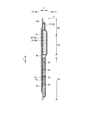
- FIG. 3 is a cross-sectional view of the absorbent article taken along line 3A-3A of FIG.
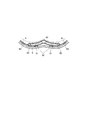
- FIG. 4 is a cross-sectional view of the absorbent article in use, taken along line 4A-4A of FIG. 1;
- 5 is a cross-sectional view of the absorbent article in use, taken along line 5A-5A of FIG. 1;
- the absorbent article may be any absorbent article such as a panty liner (cone sheet), a sanitary napkin or an incontinence pad.
- a disposable sanitary napkin will be described as an example of the absorbent article.
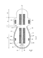
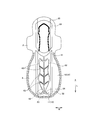
- FIG. 1 is a plan view of an absorbent article in one embodiment.
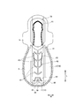
- FIG. 2 is a plan view of the absorbent article as viewed from the side opposite to FIG.
- FIG. 3 is a cross-sectional view of the absorbent article taken along line 3A-3A of FIG.
- the absorbent article 1 has a front and back direction L extending to the front side (ventral side) and a rear side (back side) of the wearer, a width direction W orthogonal to the front and back direction L, and the non-skin of the wearer And a thickness direction T extending to the facing surface side T2.
- the skin facing surface T1 corresponds to the side facing the wearer's skin at the time of use.
- the non-skin facing surface side T2 corresponds to the opposite side to the skin facing surface side T1.
- Absorbent article 1 has central area S1, front side area S2, and back side area S3.
- the central region S1 is located in an area that abuts on the wearer's excretory opening (eg, vaginal opening).
- the central region S1 is a region located at the crotch of the undergarment in a state where the absorbent article is attached to the undergarment. That is, the central area is the area that is placed between the wearer's crotch, ie, between the wearer's legs.
- the front side area S2 is located on the front side of the central area S1.
- the rear region S3 is located rearward of the central region S1. The length in the front-rear direction L of the rear region S3 may be longer than the length in the front-rear direction L of the central region S1.
- the central region S1 may be provided with wings 3 described later.
- the central region S1 can also be said to be a region in which the wing 3 is provided in the front-rear direction L.
- the hip flap 4 which bulged the outer side of the width direction W may be provided in back side area
- a width slit 41 described later may be provided at the boundary between the central area S1 and the rear area S3.
- the front edge of the width slit 41 may define the rear edge of the central area S1
- the rear edge of the width slit 41 may define the front edge of the rear area S3.
- the rear end edge of the rear area S3 defines the rear end edge of the absorbent article 1.
- the boundary between the central area S1 and the front area S2 corresponds to the front end edge of the wing 3.
- the front end edge of the wing 3 is a root of the wing 3 and is a portion located on the front side among two portions of the wing 3 which are recessed most inward in the width direction W.
- the root of the wing 3 on the front side may be located at the boundary between the central zone S1 and the front zone S2.
- the front end edge of the front side area S2 defines the front end edge of the absorbent article 1.
- the absorbent article 1 has a skin sheet 10, a non-skin sheet 20 and an absorbent body 30.
- the skin sheet 10 is provided on the skin facing surface T1 more than the absorber 30.
- the non-skin surface sheet 20 is provided closer to the non-skin facing surface T2 than the absorber 30.
- the absorber 30 is provided between the skin sheet 10 and the non-skin sheet 20.
- the skin sheet 10 may have a top sheet 11 and a side sheet 12.
- the surface sheet 11 is a liquid-permeable sheet which transmits liquid such as body fluid.
- the surface sheet 11 covers the center of at least the width direction W of the absorber 30.
- the top sheet 11 may extend from the front area S2 to the rear area S3 in the front-rear direction L.
- the side sheet 12 covers the outer edge (outside end in the width direction W) of the top sheet 11 and extends outward of the top sheet 11 in the width direction W.
- the absorbent article 1 has the side sheet 12 in the present embodiment, the absorbent article 1 may not have the side sheet 12. In this case, the top sheet 11 may cover the entire absorber 30.
- the top sheet 11 is made of a non-woven fabric, a woven fabric, a perforated plastic sheet, a mesh sheet, or any other sheet-like material having a liquid-permeable structure.
- materials for woven and non-woven fabrics either natural fibers or chemical fibers can be used.
- the side sheet 12 can be selected from the same material as the top sheet 11. However, in order to prevent the body fluid from flowing out of the absorbent article 1 over the side sheet 12, the side sheet 12 preferably has hydrophobicity or water repellency.
- the side sheets 12 are disposed on the outer edge of the absorber 30, the wings 3 and the hip flaps 4.
- the non-skin surface sheet 20 is a liquid impermeable sheet.
- the non-skin sheet 20 may be made of a polyethylene sheet, a laminated non-woven fabric mainly made of polypropylene or the like, an air-permeable resin film, a sheet having an air-permeable resin film joined to a non-woven fabric such as spunbond or spunlace. it can.
- the absorbent body 30 has an absorbent core 31 on which an absorbent material is laminated, and a core wrap 32 covering the absorbent core 31.
- the absorbent material can be formed, for example, of hydrophilic fibers, pulp and SAP.
- the absorbent core 31 is disposed at least in the central area S1 and the rear area S3.
- the absorbent core 31 may be separately disposed in each of the central area S1 and the rear area S3, or may be integrally disposed across the central area S1 and the rear area S3.
- the absorbent core 31 may extend from the central area S1 to the front area S2.
- the absorbent core 31 has a mid-high portion 33 located on the inner side in the width direction W than the outer edge 31 E of the absorbent core 31.
- the thickness of the middle high portion 33 of the absorbent core is thicker than the thickness of the absorbent core around the middle high portion 33.
- the middle and high portion 33 may be located in the central region S1.
- the basis weight of the absorbent material of the middle high portion 33 may be higher than the basis weight of the absorbent material located at the outer edge 31E of the absorbent core 31 in the central region S1.
- the mid-high portion 33 may be located on the rear side in the central region S ⁇ b> 1 and may be adjacent to the width slit 41.
- the rear edge 39 of the absorbent core 31 disposed in the rear region S3 is the inside from the outside in the width direction within the region R1 in which a pair of rear side compressed portions 84 described later in the width direction W of the absorbent article is formed. It may be inclined forward as it goes to The inclined portion of the trailing edge 39 may be connected to the front and rear slits 42 described later.
- the absorbent article 1 has the wings 3 and the hip flaps 4.
- the wings 3 and the hip flaps 4 may extend outward in the width direction W than the outer edge 31E of the absorbent core 31 in the central area S1.
- Wing 3 may have side sheet 12 and non-skin sheet 20.
- the center of the wing 3 in the front-rear direction L faces the outlet of the wearer.
- the wing 3 is configured to be foldable to the non-skin sheet 20 side.
- the wing 3 is folded back to the non-skin facing side of the crotch portion of the undergarment when in use.
- the hip flap 4 is located rearward of the wing 3 and is provided in the rear area S3.
- the hip flap 4 is not folded back at the time of use but is placed between the underwear and the buttocks of the wearer.
- the hip flap 4 is not provided with an absorbent material.
- the hip flap 4 may be provided with an absorbent material.
- the outer edge 4E of the hip flap may be formed in a corrugated shape having a large number of convex portions.
- the large number of convex portions pass from the outer edge 4E of one hip flap 4 to the rear end edge of the rear region S3 and the other hip flap It is preferable to extend to the outer edge 4E of 4.
- the large number of projections may be formed only on the outer edge 4E of the pair of hip flaps 4.
- the width of each protrusion is preferably 20 mm or less, more preferably 10 mm or less.
- variety of each convex part 4F is 3 mm or more.
- the width of the hip flap 4 in the width direction W of the absorbent article 1 may be substantially larger from the front to the rear in a region on the front side than the position P1 of the maximum width of the hip flap 4.
- the overall shape of the hip flap 4 is from the front side to the rear in the region on the front side of the position P1 of the maximum width of the hip flap 4 It is preferable that it becomes large as it goes to the side.
- a virtual line obtained by connecting the buttocks of the respective convex portions 4F formed on the outer edge 4E of the hip flap 4 is a front side in a region on the front side of the position P1 of the maximum width of the hip flap 4 And may expand monotonously to the outside in the width direction W from the rear side.
- the width of the hip flap 4 in the width direction W of the absorbent article 1 is substantially smaller from the front side to the rear side in the area on the rear side than the position P1 of the maximum width of the hip flap 4 Good.
- the width of the hip flap 4 in the width direction W of the absorbent article 1 may be substantially smaller from the front side to the rear side in a region behind the adhesive region 64 described later.
- the overall shape of the hip flap 4 is monotonous from the front side to the rear side in the area behind the adhesive area 64. It may be narrowed.
- an imaginary line obtained by connecting the buttocks of the respective convex portions 4F formed on the outer edge 4E of the hip flap 4 is directed from the front side to the rear side in the area behind the adhesive area 64.
- the position P1 of the maximum width of the hip flap is located rearward of the center of the rear region S3 in the front-rear direction L.
- the hip flap 4 may have a side seat 12 and a non-skin sheet 20. Alternatively, the hip flap 4 may not have the side seat 12. In this case, the top sheet 11 may extend to the area of the hip flap 4. In this case, the area in which a large number of convex portions are formed can be configured by the same number of sheets.
- the absorbent core 31 may have a width slit 41, an anteroposterior slit 42 and an auxiliary slit 43.
- the width slit 41, the front and rear slits 42, and the auxiliary slit 43 are formed so that the absorber 30 can be bent in the thickness direction T.
- the basis weight of the absorbent material of the width slit 41, the front and rear slits 42 and the auxiliary slit 43 is lower than the basis weight of the absorbent material of the absorbent core 31 around those slits 41, 42, 43.
- the width slit 41, the front and rear slits 42, and the auxiliary slit 43 may be a region where the basis weight of the absorbent material is zero, that is, a region where the absorbent material is not provided.
- the width slit 41, the front and rear slits 42, and the auxiliary slit 43 form a boundary where the rigidity of the absorbent article 1 changes.
- the rigidity of the region on the front side of the width slit 41 may be different from the rigidity of the region on the rear side of the width slit 41.
- the basis weight of the absorbent material in the region on the front side of the width slit 41 may be higher than the basis weight of the absorbent material of the width slit 41.
- the basis weight of the absorbent material in the region behind the width slit 41 may be higher than the basis weight of the absorbent material of the width slit 41.
- the width slit 41 extends in the width direction W between the central area S1 and the rear area S3.
- the width slit 41 may extend at least in the width direction W.
- the width slit 41 may extend linearly in parallel to the width direction W, or may extend linearly or curvilinearly at an angle to the width direction W.
- the width slit 41 of the present embodiment has a curved shape in which the center in the width direction W of the width slit 41 protrudes rearward. More specifically, the center of the width slit 41 in the width direction W is located rearward of the outer edge of the width slit 41.
- the length of the width slit 41 in the front-rear direction L may be constant or may be changed.
- the length of the width slit 41 in the front-rear direction L is preferably 10 mm or more and 50 mm or less, more preferably 10 mm or more and 30 mm or less at the position of the center line CL passing through the center of the width direction W of the absorbent article. .
- the absorber 30 can be easily bent along the wearer's skin at the width slit 41, and the absorber 30 can be fitted to the wearer's skin.
- the length of the width slit 41 in the width direction is preferably 25 mm or more. Thereby, it can control that movement of central area S1 of absorptive article 1 transmits to back side area S3.
- the width slit 41 may extend from one end to the other end in the width direction W of the absorbent core 31.
- the outer edge of the width slit 41 in the width direction W is located at the outer edge 31 E of the absorbent core 31.
- the absorbent core 31 in the central region S1 is separated from the absorbent core 31 in the rear region S3 by the width slit 41.
- the width slits 41 may extend partially in the width direction W of the absorbent core 31 across the center line CL.
- the front and rear slits 42 extend in the front and rear direction L along the center line CL of the absorbent article in the rear region S3.
- the front and rear slits 42 may extend linearly in parallel to the front and rear direction L, or may extend along the center line CL linearly or curvilinearly at an angle to the front and rear direction L.
- the front and rear slits 42 may be formed on the entire area in the front and rear direction L of the absorbent core 31 in the rear region S3. Instead of this, the front and rear slits 42 may be formed in a partial region in the front and rear direction of the absorbent core 31 in the rear region S3.
- the front end edge of the front and rear slits 42 be located 30 mm or more rearward from the center of the wing 3 in the front-rear direction L.
- the rear end edge of the front and rear slits 42 is preferably positioned 200 mm or more rearward from the center of the wing 3 in the front-rear direction L.
- the length of the front and rear direction L of the front and rear slits 42 is preferably 150 mm or more.
- a groove between the buttocks is present in the region from the back to the caudal bone than the perineal region.
- the front and rear slits 42 facilitate the deformation of the absorber 30 in a convex shape with the front and rear slits as apexes. That is, the absorber 30 is easily deformed so as to fit in the groove between the buttocks.
- the length in the width direction W of the front and rear slits 42 is 1 mm or more and 15 mm or less.
- the absorber 30 can be easily deformed so as to fit in the groove between the buttocks.
- the front and rear slits 42 may be connected to the width slit 41.
- the absorbent core 31 in the central region S1 the absorbent core 31 on one side in the width direction W of the rear region S3, and the absorbent core 31 on the other side in the width direction W of the rear region S3. Is divided. Instead of this, the front and rear slits 42 may be separated from the width slit 41.
- the auxiliary slit 43 is connected to the front and rear slits 42 and extends outward from the front and rear slits 42 in the width direction W.
- the auxiliary slit 43 may extend at least in the width direction W.
- the auxiliary slits 43 may be formed linearly in parallel to the width direction W, or may be formed linearly or in a curved manner inclined with respect to the width direction W.
- the auxiliary slits 43 are inclined forward as going from the inside to the outside in the width direction W.
- the auxiliary slits 43 respectively extend on both sides in the width direction W of the front and rear slits 42.
- a plurality of auxiliary slits 43 may be provided at intervals in the front-rear direction L.
- the outer edge of the auxiliary slit 43 in the width direction W is located inside the outer edge of the absorbent core 31 in the rear region S3. That is, on the outer side in the width direction of the auxiliary slit 43, an absorbent material is provided.
- the auxiliary slit 43 may extend to the outer edge of the absorbent core 31 of the rear zone S3.
- the auxiliary slit 43 constitutes a deformation base point at which the absorber 30 in the rear region S3 bends in the thickness direction T. That is, the absorbent article 1 is easily bent at the auxiliary slit 43. Thereby, when the absorbent article 1 is attached to the wearer, the absorber 30 is more easily fitted by the curved buttocks of the wearer.
- the absorbent article 1 has a pressed part formed by pressing at least the absorbent core 31 in the thickness direction T.
- the squeezing portion may have a front side squeezing portion 81, a longitudinal squeezing portion 82, and a pair of rear side squeezing portions 84.
- the front side pressing portion 81 is provided in the central area S1 and the front side area S2.
- the front pressing portion 81 may be formed by compressing the absorber 30 and the top sheet 11 in the thickness direction T.
- the front pressing portion 81 has a portion along the front-rear direction L provided on both sides in the width direction W of the middle high portion 33.
- the front pressing portion 81 may define side edges on both sides in the width direction W of the middle high portion 33.
- the front side pressing portion 81 is bent in the width direction near the front end edge of the absorbent core 31, and is continuously connected in a U-shape. Instead of this, the front side pressing portions 81 may be separately provided on both sides in the width direction W of the middle high portion 33. That is, a pair of front side pressing parts 81 may be separately provided in a form separated from each other.
- the longitudinal pressing portions 82 are provided on both sides of the center line CL in the rear region S3.
- the longitudinal pressing portion 82 may be formed on the front side of the position P1 of the maximum width of the hip flap 4.
- the longitudinal pressing portion 82 may be formed by compressing the absorber 30 and the surface sheet 11 in the thickness direction.
- the longitudinal pressing portion 82 extends in the front-rear direction L on both outer sides in the width direction W than the auxiliary slit 43.
- the longitudinal pressing portion 82 may extend in at least the front-rear direction L in a linear or dotted manner.
- the longitudinal pressing portion 82 may extend linearly in parallel with the front-rear direction L, or may extend curvilinearly with respect to the front-rear direction L.
- the pair of rear side pressing portions 84 are provided on both sides of the center line CL in the rear side region S3.
- the rear side pressing portion 84 may be formed by compressing the absorber 30 and the surface sheet 11 in the thickness direction.
- a pair of back side pressing parts 84 are mutually spaced apart and provided centering on center line CL which passes along the center of cross direction W of an absorptive article.
- the pair of rear side pressing portions 84 are located rearward of the position P1 of the maximum width of the hip flap 4 in the width direction W.
- the pair of rear side pressing portions 84 are located near the rear end of the rear side area S3.
- the pair of rear side pressing portions 84 are located in the vicinity of the region facing the sacrum of the wearer.
- the rear side pressing portion 84 may extend linearly or in a dotted line along the longitudinal direction L. In addition, even if it inclines or curves somewhat with respect to the front-rear direction L, the rear side pressing portion 84 is considered to extend along the front-rear direction L. Specifically, the pair of rear side pressing portions 84 may extend partially or entirely along the longitudinal direction L. The pair of rear side pressing portions 84 have wide sections in which the distance in the width direction W spreads toward the rear side. That is, the rear side pressing portion 84 is inclined outward in the width direction W as it goes to the rear side.
- the pair of longitudinal compressions 82 are spaced apart from the pair of rear compressions 84.
- the distance between the pair of longitudinal compressions 82 and the pair of back compressions 84 is preferably at least 1 cm, more preferably at least 3 cm.
- the section in which a pressing part is not formed between a pair of longitudinal pressing parts 82 and a pair of back side pressing parts 84 may straddle position P1 of the maximum width of a hip flap.
- a portion of the absorbent core 31 provided in the rear region S3 is disposed in the wide region R1 sandwiched by the wide sections. Further, it is preferable that a part of the front and rear slits 42 extend the wide region R1. It is more preferable that the front and rear slits 42 penetrate the wide region R1 along the front and rear direction L.
- the absorbent article 1 is a first compressed portion 85 formed by compressing at least two of the sheets constituting the skin side sheet 10 and the non-skin side sheet 20 in the thickness direction T, and a second compressed portion. It has 87 and the 3rd pressing part 86.
- the first squeezing portion 85, the second squeezing portion 87 and the third squeezing portion 86 are formed at least along the outer edge 4 E of the hip flap 4.
- the absorbent article 1 is provided with a first main adhesive region 61, a second main adhesive region 62, and a wing provided with an adhesive for stopping the absorbent article 1 on the underwear S.
- An adhesive area 63 and a hip flap adhesive area 64 are provided. These adhesive regions 61 to 64 are provided on the non-skin facing surface of the non-skin surface sheet 20.
- the adhesive areas 61 to 64 may be covered with a release sheet in a state before use. The release sheet prevents the deterioration of the adhesive in the adhesive areas 61 to 64 before use. Peeling sheet 65 is peeled off by the wearer when in use.
- the first main body adhesive area 61 is disposed in front of the second main body adhesive area 62.
- the first main body adhesive area 61 is spaced from the second main body adhesive area 62 in the front-rear direction L.
- the first main adhesive region 61 may be disposed on the front side of the width slit 41 and across the central region S1 and the front region S2.
- the second main body adhesive area 62 is disposed in the rear area S ⁇ b> 3 behind the width slit 41.
- the wing adhesion area 63 is provided on the wing 3.
- the hip flap adhesive area 64 is provided on the hip flap 4.
- the width slits 41 and the front and rear slits 42 do not overlap with all the adhesive regions 61 to 64 in the thickness direction T.
- the adhesive regions 61 to 64 are not provided in the region where the width slit 41 and the front and rear slits 42 are disposed in plan view.
- the wide region R1 sandwiched by the pair of rear side pressing portions 84 may be disposed in a region not overlapping the adhesive regions 61 to 64.
- the first squeezing portion 85, the second squeezing portion 87 and the third squeezing portion 86 extend between the outer edge 4E of the hip flap 4 and the hip flap adhesive area 64.
- no adhesive area is provided outside the hip flap adhesive area 64 in the width direction W.
- the cross-sectional shape of the body of the wearer along the width direction W of the absorbent article 1 differs between the vicinity of the crotch and the vicinity of the buttocks.
- the cross-sectional shape of the body in the vicinity of the wearer's crotch navy cleft is that the labia majora protrudes above the base of the labia minora and projects toward the absorbent article 1 side It has a convex shape.
- the central region S1 of the absorbent article is disposed to be opposed.
- the absorbent article 1 is worn on the undergarment S and worn by the wearer, the absorbent core of the central area S1 is pushed down to the bulge of the labia majora and deformed so as to bulge on the non-skin facing surface side.
- the absorbent core of the central region S1 can be placed along the body to control leakage in the crotch.
- the anus and the anal fissure is located behind the perineum located behind the wearer's labia majora.
- the cross-sectional shape of the body along the width direction near the rear than the perineal region is a shape in which the center in the width direction is recessed.
- the back area S3 of the absorbent article is disposed to face the buttocks of the wearer.
- FIG. 4 is a cross-sectional view of the rear area S3 of the absorbent article in a state of being worn by the wearer.
- FIG. 4 corresponds to a cross section taken along line 4A-4A of FIG.
- the line which shows a wearer's body is shown by the dashed-two dotted line.
- sanitary napkins for night are often used in a sleeping posture on the back.
- menstrual blood may be transmitted through the body to the rear of the back side and leak from the back of the absorbent article.
- the side portions of the absorbent core 31 are pushed down by the left and right buttocks in the rear region S3. Therefore, a force is applied to the side portion in the width direction of the absorbent core in the rear region than in the center in the width direction of the absorbent core 31 in the rear region.
- the widthwise center of the absorber in the back region bulges toward the wearer with the front and rear slits 42 as the apexes.
- the center in the width direction of the absorbent core 31 in the rear region S3 can be easily disposed in the recess between the buttocks, and the absorbent core 31 can be fitted along the buttocks of the wearer. As a result, it is possible to prevent body fluid such as menstrual blood from passing through the body and flowing backward and leaking from the back of the absorbent article.
- the palpebral region of the wearer becomes shallower towards the rear (back side).
- a sacrum is present behind the palpebral fissure.
- the cross-sectional shape of the body in the area where the sacrum is present is a flatter shape than the area in which the groin is present.
- the wide region R1 provided at the rear of the rear region S3 of the absorbent article 1 or a region rearward of the wide region R1 is disposed to face the portion of the sacrum of the wearer.
- FIG. 5 corresponds to a cross section taken along line 5A-5A of FIG.
- the relatively front area of the rear side area S3 bulges toward the wearer with the front and rear slits 42 as the apex. With such deformation, the central portion in the width direction W of the relatively rear region of the rear region S3 tends to rise.
- the absorbent core 31 forms a relatively flat surface FS in the wide region R1.
- FIG. 6 is a plan view of an absorbent article according to another embodiment.
- the same components as those of the above-described embodiment are denoted by the same reference numerals. In the following, configurations different from the above embodiment will be mainly described.
- the absorbent article shown in FIG. 6 differs from the absorbent article 1 shown in FIG. 1 in the length of the front and rear slits 42 and the shape of the rear edge 39 of the absorbent core 31 disposed in the rear region S3.
- the front and rear slits 42 do not extend to the rear edge 39 of the absorbent core 31 disposed in the rear region S3.
- the rear edge 39 of the absorbent core 31 disposed in the rear region S3 is from the outside in the width direction within the wide region R1 in which a pair of rear side compressed portions 84 described later in the width direction W of the absorbent article is formed. It is inclined forward as it goes inward. Furthermore, the sloped portion of the trailing edge 39 extends into the wide region R1, and forms a rear slit 44 in the wide region R1.
- the rear slit 44 is provided in a part of the wide region R1. Alternatively, the rear slit 44 may penetrate the wide region R1 in the front-rear direction L along the center line.
- the rear slit 44 may be an area of zero weight of the absorbent material, that is, a region where no absorbent material is provided.
- the rear slit 44 may be an area provided with an absorbent material lower than the weight of the absorbent material of the absorbent core 31 around the slit 44.
- FIG. 7 is a plan view of an absorbent article according to still another embodiment.
- the same components as those in the above-described embodiment are denoted by the same reference numerals. In the following, configurations different from the above embodiment will be mainly described.
- the longitudinal pressing portion 82 provided in the rear region extends long in the front-rear direction L, and is connected to the rear side pressing portion 84 provided in the rear of the rear region.
- the longitudinal pressing portion 82 points to a portion on the front side of the position P1 of the maximum width of the hip flap 4.
- the rear side pressing part 84 shall point out the part of the back side rather than the position P1 of the largest width of the hip flap 4.
- the rear side pressing parts 84 are provided on both sides across the center line CL in the width direction W.
- the distance between the pair of rear side pressing portions 84 is reduced at one end toward the rear side, and spreads further toward the rear side.
- a pair of back side pressing parts 84 have a wide section to which the distance of the cross direction W spreads as it goes to the back side.
- a region sandwiched by the wide sections of the pair of rear side pressing portions 84 corresponds to the wide region R1. Even in this case, as described in FIG. 5, the wide region R1 is formed on the relatively flat surface FS.
- the pair of rear side pressing portions 84 are located rearward of the position of the maximum width of the hip flap in the width direction, and the pair of rear side pressing portions 84 are It has a wide section in which the distance in the width direction spreads toward the side.
- the maximum width of the hip flap in the width direction is located behind the center of the rear area in the front-rear direction.
- the wide region R1 sandwiched by the wide sections corresponds to the vicinity of the wearer's sacrum. There are no squeezed parts in this area, and a relatively rigid pair of squeezed parts 84 exists on both sides of this area. Thus, the wide region R1 is maintained on the relatively flat surface FS. Since the relatively flat surface FS strikes the skin near the sacrum, the influence on the skin of the wearer can be reduced.
- the pair of pressing portions 84 are arranged to divide between a region facing the vicinity of the sacrum and a portion facing the thick portion of the buttocks. Since the buttocks move relatively violently, the part facing the buttocks of the absorbent article 1 is also easy to move according to the movement of the wearer. The movement of the absorbent article 1 is less likely to be transmitted to the region facing the sacrum, that is, the wide region R1, by the pair of relatively high-pressure pressing portions 84. As a result, the wide region R1 can be maintained on the relatively flat surface FS, and the influence on the wearer's skin can be reduced. Moreover, it is preferable that there is no rigid high compression part in wide area
- the absorbent article 1 has the non-skin surface sheet 20 provided on the non-skin facing surface side with respect to the absorbent core 31 and the adhesive region provided on the non-skin facing surface of the non-skin surface sheet 20. 61 to 64. Further, a region R1 sandwiched by the wide sections of the pair of pressing portions 84 and 184 is disposed in a region not overlapping the adhesive regions 61 to 64. Absorbent article 1 is used in the state where it was pinched between a wearer and underwear. The adhesive regions 61 to 64 attached to the underwear rub against each other between the wearer and the underwear, so wrinkles are likely to occur.
- the wide region R1 ie, the region facing the sacrum
- FIG. As a result, the region of the absorbent article 1 facing the sacrum can be maintained in a flatter shape.
- the absorbent core 31 disposed in the rear region S3 has slits 42 or 44 extending from the rear edge in the front-rear direction L of the absorbent article 1 into the wide region R1, and the slits It consists of a region where no absorbent material is provided, or a region where an absorbent material with a lower basis weight than the absorbent core 31 disposed in the rear region S3 is provided.
- the absorbent core 31 on the left side of the center line CL of the absorbent article 1 tries to move to the right.
- the absorbent core 31 on the right side of the center line CL tries to move to the left.
- the absorbent core 31 disposed in the rear region S3 has the front and rear slits 42 extending along the center line CL passing through the center of the width direction W of the absorbent article 1, and the front and rear slits 42 It consists of a region where no absorbent material is provided, or a region where an absorbent material with a lower basis weight than the absorbent core 31 disposed in the rear region S3 is provided. As described above, the side portions of the absorbent core 31 are pushed down by the left and right buttocks in the rear region S3.
- the widthwise center of the absorber in the back region bulges toward the wearer with the front and rear slits 42 as the apexes. Therefore, the center in the width direction of the absorbent core 31 in the rear region S3 can be easily disposed in the recess between the buttocks, and the absorbent core 31 can be fitted along the buttocks of the wearer. As a result, it is possible to prevent body fluid such as menstrual blood from passing through the body and flowing backward and leaking from the back of the absorbent article.
- the deformation of the absorbent core 31 affects the wide region R1 of the pair of compressed portions 84.
- the wide region R1 that is, the region facing the sacrum, slightly bulges toward the wearer's skin while maintaining the relatively flat surface FS (see also FIG. 5).
- the area behind the back side area S3 also easily conforms to the wearer's skin.
- At least the absorbent core 31 is squeezed, and the pair of longitudinal squeezed portions 82 provided on both sides across the center line CL is more than the position of the maximum width of the hip flap 4 in the rear area S3. It is formed on the front side.
- the pair of longitudinal pressing portions 82 serve as a base point of the deformation of the absorbent core 31 and cause the region of the front and rear slits 42 to bulge toward the wearer.
- absorber 30 can be made easy to fit in a crevice between a wearer's buttocks.
- the pair of longitudinal compressions 82 are spaced apart from the pair of back compressions 84. Thereby, it can suppress that movement of an absorption core behind back side field S3 follows movement of an absorption core ahead of back side field S3.
- the absorbent core in front of the back area S3 may move relatively large in accordance with the movement of the wearer's hip.
- the pair of longitudinal pressing portions 82 and the pair of rear side pressing portions 84 are separated from each other, the movement of the absorbent core behind the rear side region S3 is alleviated. Ru. Therefore, the movement of the absorbent core in the wide region R1 is alleviated, and therefore the stimulation given to the wearer's sacrum can be reduced.
- a width slit 41 extending along the width direction W of the absorbent article is provided between the absorbent core disposed in the central region S1 and the absorbent core disposed in the rear region S3.
- the width slit 41 is formed of an area where no absorbent material is provided, or an area where an absorbent material with a lower weight than absorbent cores disposed in the central area and the rear area is provided.
- the boundary between the width slit 41 and the absorbent core of the central region S1 can be a deformation starting point of the absorbent article.
- the boundary between the width slit 41 and the absorbent core of the rear region S3 can be a deformation starting point of the absorbent article.
- the absorbent article 1 can be flexibly deformed along the deformation of the buttocks when the swelling of the buttocks of the wearer is crushed.
- the width slit 41 is easily deformed flexibly because it is composed of a region where no absorbent material is provided, or a region where an absorbent material with a lower basis weight than the absorbent core disposed in the central region and the rear region is provided.
- the crushed part of the buttocks of the wearer moves to the crotch side, the deformation of the buttocks is absorbed by the width slits 41, and it becomes easy to keep the area before and after the width slits 41 applied to the wearer.
- the force applied to the absorbent core in the central region S1 can be suppressed from being transmitted to the absorbent core in the rear region S3 by the width slit 41.
- the absorbent core disposed in the central region S1 is located inside in the width direction than the outer edge of the absorbent core, and has a mid-high portion 33 thicker than the thickness of the outer edge of the absorbent core.
- the middle high portion 33 is adjacent to the width slit 41.
- the rear edge 39 of the absorbent core 31 disposed in the rear region S3 is in the width direction within the region R1 in which the pair of compressed portions 84 in the width direction W of the absorbent article 1 is formed. It inclines to the front side as it goes inward from the outside of W.
- the absorbent core 31 on the left side of the center line CL of the absorbent article 1 tries to move to the right.
- the absorbent core 31 on the right side of the center line CL tries to move to the left.
- the wide region R1 of the absorbent core 31 may be deformed to a strain near the center line CL due to a force collision.
- the trailing edge 39 of the absorbent core 31 is inclined forward in the wide region R1 in the width direction W of the absorbent article 1 from the outside in the width direction W toward the inside. This inclination makes it difficult for the left and right absorbent cores 31 to collide with each other at the trailing edge 39 of the absorbent core 31, and the force is relaxed.
- the shape of the wide region R1 is prevented from being broken. As a result, the wide region R1 can be maintained on a flatter surface.
Landscapes
- Health & Medical Sciences (AREA)
- Epidemiology (AREA)
- Engineering & Computer Science (AREA)
- Biomedical Technology (AREA)
- Heart & Thoracic Surgery (AREA)
- Vascular Medicine (AREA)
- Life Sciences & Earth Sciences (AREA)
- Animal Behavior & Ethology (AREA)
- General Health & Medical Sciences (AREA)
- Public Health (AREA)
- Veterinary Medicine (AREA)
- Absorbent Articles And Supports Therefor (AREA)
Abstract
仙骨付近の皮膚に対する刺激を緩和することができる吸収性物品を提供する。吸収性物品(1)は、着用者の股下に配置される中央域(S1)と、中央域(S1)よりも前後方向(L)の長さが長い後側域(S3)と、少なくとも後側域(S3)に配置される吸収コア(31)と、を有し、後側域(S3)には、幅方向(W)の外側に膨らんだヒップフラップ(4)が設けられており、少なくとも吸収コア(31)を圧搾し、中心線(CL)を挟んで互いに離間して設けられた一対の後側圧搾部(84)が、後側域(S3)に前後方向(L)に沿って形成されており、ヒップフラップ(4)の最大幅は、前後方向(L)における後側域(S3)の中央よりも後側に位置しており、一対の後側圧搾部(84)は、ヒップフラップ(4)の最大幅の位置(P1)よりも後側に位置し、一対の後側圧搾部(84)は、後側に向かうにつれて幅方向Wの距離が広がる幅広区間を有する。
Description
本発明は、生理用ナプキン等の吸収性物品に関する。
経血やおりものなどを吸収するための生理用ナプキン、パンティーライナー、失禁パッド等の吸収性物品が知られている。吸収性物品のうち特に生理用ナプキンは、下着により着用者の体の方に押し当てられ、着用者の体にフィットされるようにして使用される。特許文献1は、経血やおりものなどを吸収するための生理用ナプキン、パンティーライナー、失禁パッド等の吸収性物品を開示している。吸収性物品は、表面シート、裏面シート及び吸収体を有する。吸収体は、表面シートと裏面シートとの間に設けられている。吸収性物品は、少なくとも表面シートと吸収体とを圧搾したエンボスパターンを有する。エンボスパターンは、着用時に吸収性物品、特に吸収体の曲がり方を制御するように形成される。特許文献1では、臀部の溝(臀裂)に確実にフィットするとともに、就寝時の臀部の潰れに対応してフィットできるようにするために、エンボスパターンが形成されている。
本願の発明者は、例えば使い捨てナプキンのような吸収性物品について、以下のような課題を発見した。吸収性物品の前後方向の後端部付近は、着用者の仙骨の位置に相当する。人の仙骨周辺は突出しており、仙骨の位置における脂肪や筋肉は薄い。したがって、人の仙骨付近の部分は柔らかく、吸収性物品が仙骨付近の皮膚に刺激を与えることがある。
そこで、本発明は、上述の課題に鑑みてなされたものであり、仙骨付近の皮膚に対する刺激を緩和できる吸収性物品を提供することを目的とする。
本開示に係る吸収性物品は、互いに直交する前後方向及び幅方向と、着用者の股下に配置される中央域と、前記中央域の後側に位置し、前記中央域よりも前後方向の長さが長い後側域と、少なくとも前記後側域に配置される吸収コアと、を有し、前記後側域には、前記幅方向の外側に膨らんだヒップフラップが設けられており、少なくとも前記吸収コアを圧搾し、前記吸収性物品の前記幅方向の中心を通る中心線を挟んで互いに離間して設けられた一対の後側圧搾部が、前記後側域に前記前後方向に沿って形成されており、前記幅方向における前記ヒップフラップの最大幅は、前記前後方向における前記後側域の中央よりも後側に位置しており、前記一対の後側圧搾部は、前記幅方向における前記ヒップフラップの最大幅の位置よりも後側に位置し、前記一対の後側圧搾部は、後側に向かうにつれて前記幅方向の距離が広がる幅広区間を有する。
以下、図面を参照して、実施形態に係る吸収性物品ついて説明する。吸収性物品は、パンティーライナー(おりものシート)や生理用ナプキンや失禁パッド等の任意の吸収性物品であってよい。以下の実施形態では、吸収性物品の一例として使い捨ての生理用ナプキンについて説明する。
なお、以下の図面の記載において、同一又は類似の部分には、同一又は類似の符号を付している。ただし、図面は模式的なものであり、各寸法の比率等は現実のものとは異なることに留意すべきである。したがって、具体的な寸法等は、以下の説明を参酌して判断すべきである。また、図面相互間においても互いの寸法の関係や比率が異なる部分が含まれ得る。
(1)吸収性物品の全体的構成
図1は、一実施形態における吸収性物品の平面図である。図2は、図1とは反対側から見た吸収性物品の平面図である。図3は、図1の3A-3A線に沿った吸収性物品の断面図である。
図1は、一実施形態における吸収性物品の平面図である。図2は、図1とは反対側から見た吸収性物品の平面図である。図3は、図1の3A-3A線に沿った吸収性物品の断面図である。
吸収性物品1は、着用者の前側(腹側)及び後側(背側)に延びる前後方向Lと、前後方向Lと直交する幅方向Wと、着用者の肌対向面側T1から非肌対向面側T2へ延びる厚み方向Tと、を有する。肌対向面側T1は、使用時に、着用者の肌に対向する側に相当する。非肌対向面側T2は、肌対向面側T1とは反対側に相当する。
吸収性物品1は、中央域S1、前側域S2及び後側域S3を有する。中央域S1は、着用者の排泄口(例えば膣口)に当接する領域に位置する。中央域S1は、吸収性物品が下着に装着された状態で、下着の股下部に位置する領域である。つまり、中央域は、着用者の股下、すなわち着用者の両足の間に配置される領域である。前側域S2は、中央域S1よりも前側に位置する。後側域S3は、中央域S1よりも後側に位置する。後側域S3の前後方向Lの長さは、中央域S1の前後方向Lの長さよりも長くなっていてよい。
中央域S1には、後述するウイング3が設けられていてよい。この場合、中央域S1は、前後方向Lにおいてウイング3が設けられている領域とも言える。また、後側域S3には、幅方向Wの外側に膨らんだヒップフラップ4が設けられていてよい。
中央域S1と後側域S3の境界に、後述する幅スリット41が設けられていてよい。この場合、幅スリット41の前端縁が中央域S1の後端縁を規定してもよく、幅スリット41の後端縁が後側域S3の前端縁を規定してもよい。
後側域S3の後端縁は吸収性物品1の後端縁を規定する。中央域S1と前側域S2の境界はウイング3の前端縁に相当する。ウイング3の前端縁は、ウイング3の付け根であり、ウイング3において最も幅方向Wの内側に窪んだ2つの部分のうち、前側に位置する部分である。ウイング3の前側の付け根は、中央域S1と前側域S2との境界に位置してもよい。前側域S2の前端縁は吸収性物品1の前端縁を規定する。
吸収性物品1は、肌面シート10、非肌面シート20及び吸収体30を有する。肌面シート10は、吸収体30よりも肌対向面側T1に設けられる。非肌面シート20は、吸収体30よりも非肌対向面側T2に設けられる。吸収体30は、肌面シート10と非肌面シート20との間に設けられる。
肌面シート10は、表面シート11とサイドシート12を有していてよい。表面シート11は、体液等の液体を透過する液透過性のシートである。表面シート11は、吸収体30の少なくとも幅方向Wの中央を覆う。表面シート11は、前後方向Lに前側域S2から後側域S3まで延びていてよい。サイドシート12は、表面シート11の外側縁(幅方向Wの外側端部)を覆い、表面シート11よりも幅方向Wの外側に延びている。なお、本実施形態では、吸収性物品1はサイドシート12を有しているが、吸収性物品1はサイドシート12を有していなくてもよい。この場合、表面シート11は吸収体30全体を覆っていてよい。
表面シート11は、不織布、織布、有孔プラスチックシート、メッシュシート等、液体を透過する構造を有する任意のシート状の材料から構成される。織布や不織布の素材としては、天然繊維、化学繊維のいずれも使用できる。
サイドシート12は、表面シート11と同様の材料から選ぶことができる。但し、サイドシート12を乗り越えて吸収性物品1の外方へ体液が流出することを防止するためには、サイドシート12は、疎水性又は撥水性を有することが好ましい。サイドシート12は、吸収体30の外側縁、ウイング3及びヒップフラップ4に配置されている。
非肌面シート20は、液不透過性のシートである。非肌面シート20は、ポリエチレンシート、ポリプロピレン等を主体としたラミネート不織布、通気性の樹脂フィルム、スパンボンド、又はスパンレース等の不織布に通気性の樹脂フィルムが接合されたシートなどを用いることができる。
吸収体30は、吸収材料が積層された吸収コア31と、吸収コア31を覆うコアラップ32と、を有する。吸収材料は、例えば、親水性繊維、パルプ及びSAPから形成できる。
吸収コア31は、少なくとも中央域S1と後側域S3に配置される。なお、吸収コア31は、中央域S1と後側域S3のそれぞれに別個に配置されていてもよいし、中央域S1と後側域S3に跨って一体的に配置されていてもよい。また、吸収コア31は、中央域S1から前側域S2にまで延びていてもよい。
吸収コア31は、吸収コア31の外側縁31Eよりも幅方向Wの内側に位置する中高部33を有する。吸収コアの中高部33の厚みは、中高部33のまわりの吸収コアの厚みよりも厚い。中高部33は、中央域S1に位置していてよい。中高部33の吸収材料の目付は、中央域S1における吸収コア31の外側縁31Eに位置する吸収材料の目付よりも高くてもよい。中高部33は、中央域S1内の後側に位置し、幅スリット41に隣接していてよい。
後側域S3に配置される吸収コア31の後縁39は、吸収性物品の幅方向Wにおける後述の一対の後側圧搾部84が形成されている領域R1内で、幅方向の外側から内側に向かうにつれて前側に傾斜していてよい。この後縁39の傾斜部は、後述の前後スリット42と繋がっていてもよい。
前述したように、吸収性物品1は、ウイング3及びヒップフラップ4を有する。ウイング3及びヒップフラップ4は、中央域S1の吸収コア31の外側縁31Eよりも幅方向Wの外側に延出していてよい。
ウイング3は、サイドシート12と非肌面シート20を有していてよい。ウイング3の前後方向Lの中心は、着用者の排泄口に対向する。ウイング3は、非肌面シート20側に折り返し可能に構成されている。ウイング3は、使用時に下着のクロッチ部の非肌対向面側に折り返される。
ヒップフラップ4は、ウイング3よりも後側に位置し、後側域S3に設けられている。ヒップフラップ4は、使用時に折り返されず、下着と着用者の臀部との間に配置される。本実施形態では、ヒップフラップ4には吸収材料が設けられていない。この代わりに、ヒップフラップ4には、吸収材料が設けられていてもよい。
ヒップフラップの外縁4Eは、多数の凸部を有する波形形状に形成されていてよい多数の凸部は、一方のヒップフラップ4の外縁4Eから後側域S3の後端縁を経て他方のヒップフラップ4の外縁4Eまで延びていることが好ましい。この代わりに、多数の凸部は、一対のヒップフラップ4の外縁4Eのみに形成されていてもよい。各々の凸部の幅は、好ましくは20mm以下、より好ましくは10mm以下である。また、各々の凸部4Fの幅は、3mm以上であることが好ましい。
吸収性物品1の幅方向Wにおけるヒップフラップ4の幅は、ヒップフラップ4の最大幅の位置P1よりも前側の領域において、前側から後側に向かうにつれて実質的に大きくなっていてもよい。具体的には、ヒップフラップの外縁4Eの凸部4Fの形を考慮せず、ヒップフラップ4の全体的な形状が、ヒップフラップ4の最大幅の位置P1よりも前側の領域において、前側から後側に向かうにつれて大きくなっていることが好ましい。より具体的には、ヒップフラップ4の外縁4Eに形成された各々の凸部4Fの麓部を結んで得られる仮想線が、ヒップフラップ4の最大幅の位置P1よりも前側の領域において、前側から後側に向かうにつれて幅方向Wの外側に単調に膨らんでいてよい。
また、吸収性物品1の幅方向Wにおけるヒップフラップ4の幅は、ヒップフラップ4の最大幅の位置P1よりも後側の領域において、前側から後側に向かうにつれて実質的に小さくなっていてもよい。この代わりに、吸収性物品1の幅方向Wにおけるヒップフラップ4の幅は、後述する粘着領域64よりも後側の領域において、前側から後側に向かうにつれて実質的に小さくなっていてもよい。具体的には、ヒップフラップの外縁4Eの凸部4Fの形を考慮せず、ヒップフラップ4の全体的な形状が、粘着領域64よりも後側の領域において、前側から後側に向かうにつれて単調に狭くなっていてよい。より具体的には、ヒップフラップ4の外縁4Eに形成された各々の凸部4Fの麓部を結んで得られる仮想線が、粘着領域64よりも後側の領域において、前側から後側に向かうにつれて幅方向Wの内側に単調に狭くなっている。なお、ヒップフラップの最大幅の位置P1は、前後方向Lにおける後側域S3の中央よりも後側に位置している。
ヒップフラップ4は、サイドシート12と非肌面シート20を有していてよい。この代わりに、ヒップフラップ4はサイドシート12を有していなくてもよい。この場合、表面シート11がヒップフラップ4の領域まで延びていればよい。この場合、多数の凸部が形成された領域を、同一の枚数のシートによって構成することができる。
(2)吸収コアのスリット
吸収コア31は、幅スリット41、前後スリット42及び補助スリット43を有していてよい。幅スリット41、前後スリット42及び補助スリット43は、吸収体30を厚み方向Tに曲げることができるように形成されている。
吸収コア31は、幅スリット41、前後スリット42及び補助スリット43を有していてよい。幅スリット41、前後スリット42及び補助スリット43は、吸収体30を厚み方向Tに曲げることができるように形成されている。
幅スリット41、前後スリット42及び補助スリット43の吸収材料の目付は、それらのスリット41,42,43のまわりの吸収コア31の吸収材料の目付よりも低い。なお、幅スリット41、前後スリット42及び補助スリット43は、吸収材料の目付が0の領域、すなわち吸収材料が設けられていない領域であってもよい。
幅スリット41、前後スリット42及び補助スリット43は、吸収性物品1の剛性が変化する境目となる。例えば、幅スリット41よりも前側の領域の剛性は、幅スリット41よりも後側の領域の剛性と異なっていてよい。より詳細には、幅スリット41よりも前側の領域の吸収材料の目付は、幅スリット41の吸収材料の目付よりも高くてよい。また、幅スリット41よりも後側の領域の吸収材料の目付は、幅スリット41の吸収材料の目付よりも高くてよい。
幅スリット41は、中央域S1と後側域S3との間で幅方向Wに延びる。幅スリット41は、少なくとも幅方向Wに延びていればよい。幅スリット41は、幅方向Wに平行に直線的に延びていてもよいし、幅方向Wに対して傾斜して直線的又は曲線的に延びていてもよい。
本実施形態の幅スリット41は、幅スリット41の幅方向Wの中央が後方に突出した曲線形状である。より詳細には、幅スリット41の幅方向Wの中心は、幅スリット41の外側縁よりも後方に位置する。幅スリット41の前後方向Lにおける長さは、一定であってもよいし、変化していてもよい。幅スリット41の前後方向Lの長さは、吸収性物品の幅方向Wの中心を通る中心線CLの位置で、好ましくは10mm以上かつ50mm以下であり、より好ましくは10mm以上かつ30mm以下である。これにより、吸収体30が幅スリット41のところで着用者の肌に沿って曲がり易くなり、吸収体30を着用者の肌にフィットさせることができる。
幅スリット41の幅方向の長さは、25mm以上であることが好ましい。これにより、吸収性物品1の中央域S1の動きが、後側域S3に伝わることを抑制できる。
幅スリット41は、吸収コア31の幅方向Wの一端から他端まで延びていてもよい。この場合、幅スリット41の幅方向Wの外側縁は、吸収コア31の外側縁31Eに位置する。これにより、中央域S1の吸収コア31は、幅スリット41によって後側域S3の吸収コア31から分断される。この代わりに、幅スリット41は、中心線CLを跨ぎ、かつ吸収コア31の幅方向Wに部分的に延びていてもよい。
前後スリット42は、後側域S3において、吸収性物品の中心線CLに沿って前後方向Lに延びる。前後スリット42は、前後方向Lに平行に直線的に延びていてもよいし、前後方向Lに対して傾斜して直線的又は曲線的に、中心線CLに沿って延びていてもよい。前後スリット42は、後側域S3の吸収コア31の前後方向Lの全域に形成されていてもよい。この代わりに、前後スリット42は、後側域S3の吸収コア31の前後方向の一部の領域に形成されていてもよい。
前後スリット42の前端縁は、ウイング3の前後方向Lの中心から30mm以上後方に位置することが好ましい。前後スリット42の後端縁は、ウイング3の前後方向Lの中心から200mm以上後方に位置することが好ましい。前後スリット42の前後方向Lの長さは、150mm以上であることが好ましい。着用者の身体の前後方向Lに沿った断面において、臀部間の溝(臀裂)は、会陰部よりも後方から尾てい骨に至る領域に存在する。前後スリット42は、前後スリットを頂点として凸状に吸収体30を変形させ易くする。すなわち、吸収体30が臀部間の溝にフィットするように変形し易くなる。
好ましくは、前後スリット42の幅方向Wの長さは、1mm以上かつ15mm以下である。これにより、臀部間の溝にフィットするように吸収体30を変形させ易くすることができる。
前後スリット42は、幅スリット41と繋がっていてもよい。この場合、平面視にて、中央域S1の吸収コア31と、後側域S3の幅方向Wの一方側の吸収コア31と、後側域S3の幅方向Wの他方側の吸収コア31とは、分断されている。この代わりに、前後スリット42は、幅スリット41と離間していてもよい。
補助スリット43は、前後スリット42に繋がっており、かつ前後スリット42から幅方向Wの外側に延びる。補助スリット43は、少なくとも幅方向Wに延びていればよい。補助スリット43は、幅方向Wに平行に直線的に形成されていてもよいし、幅方向Wに対して傾斜して直線的又は曲線的に形成されていてもよい。補助スリット43は、幅方向Wの内側から外側に向かうにつれて前側に傾斜していることが好ましい。補助スリット43は、前後スリット42の幅方向Wの両側にそれぞれ延びている。補助スリット43は、前後方向Lに間隔を空けて複数設けられていてよい。
補助スリット43の幅方向Wの外側縁は、後側域S3の吸収コア31の外側縁よりも内側に位置する。すなわち、補助スリット43の幅方向の外側には、吸収材料が設けられている。この代わりに、補助スリット43は、後側域S3の吸収コア31の外側縁まで延びていてもよい。
補助スリット43は、後側域S3の吸収体30が厚み方向Tに曲がる変形基点を構成する。すなわち、吸収性物品1は補助スリット43のところで曲がり易くなっている。これにより、吸収性物品1が着用者に取り付けられたときに、吸収体30が、着用者の湾曲した臀部によりフィットし易くなる。
(3)圧搾部
吸収性物品1は、少なくとも吸収コア31が厚み方向Tに圧搾されることによって形成された圧搾部を有する。この圧搾部は、前側圧搾部81と、長手圧搾部82と、一対の後側圧搾部84と、を有していてよい。
吸収性物品1は、少なくとも吸収コア31が厚み方向Tに圧搾されることによって形成された圧搾部を有する。この圧搾部は、前側圧搾部81と、長手圧搾部82と、一対の後側圧搾部84と、を有していてよい。
前側圧搾部81は、中央域S1及び前側域S2に設けられている。前側圧搾部81は、吸収体30と表面シート11とが厚み方向Tに圧縮されることによって形成されていてよい。前側圧搾部81は、中高部33の幅方向W両側に設けられた前後方向Lに沿った部分を有する。前側圧搾部81は、中高部33の幅方向W両側の側縁を規定していてよい。
前側圧搾部81は、吸収コア31の前端縁付近で幅方向に向かって曲がっており、U字型に連続的に繋がっている。この代わりに、前側圧搾部81は、中高部33の幅方向W両側に、別個に設けられていても良い。すなわち、一対の前側圧搾部81が、互いに分断された形態で、別個に設けられていても良い。
長手圧搾部82は、後側域S3で、中心線CLを挟んで両側に設けられている。長手圧搾部82は、ヒップフラップ4の最大幅の位置P1よりも前側に形成されていてよい。長手圧搾部82は、吸収体30と表面シート11とが厚み方向に圧縮されることによって形成されていてよい。長手圧搾部82は、補助スリット43よりも幅方向Wの両外側において前後方向Lに延びる。長手圧搾部82は、線状又は点線状に、少なくとも前後方向Lに延びていればよい。長手圧搾部82は、前後方向Lに平行に直線的に延びていてもよいし、前後方向Lに対して傾斜して曲線的に延びていてもよい。
一対の後側圧搾部84は、後側域S3で、中心線CLを挟んで両側に設けられている。後側圧搾部84は、吸収体30と表面シート11とが厚み方向に圧縮されることによって形成されていてよい。一対の後側圧搾部84は、吸収性物品の幅方向Wの中心を通る中心線CLを挟んで互いに離間して設けられている。一対の後側圧搾部84は、幅方向Wにおけるヒップフラップ4の最大幅の位置P1よりも後側に位置する。好ましくは、一対の後側圧搾部84は、後側域S3の後側の端部付近に位置する。具体的には、一対の後側圧搾部84は、着用者の仙骨に対向する領域近傍に位置する。後側圧搾部84は、前後方向Lに沿って線状又は点線状に延びていてよい。なお、前後方向Lに対して多少傾斜又は湾曲していても、後側圧搾部84は、前後方向Lに沿って延びていると見なす。具体的には、一対の後側圧搾部84は、部分的又は全体的に前後方向Lに沿って延びていてよい。一対の後側圧搾部84は、後側に向かうにつれて幅方向Wの距離が広がる幅広区間を有する。すなわち、後側圧搾部84は、後側へ向かうにつれて、幅方向Wの外側に傾斜している。
図1に示す実施形態では、一対の長手圧搾部82は、一対の後側圧搾部84から離れて配置されている。一対の長手圧搾部82と一対の後側圧搾部84との間の距離は、好ましくは少なくとも1cm、より好ましくは少なくとも3cmである。一対の長手圧搾部82と一対の後側圧搾部84との間の、圧搾部が形成されていない区間は、ヒップフラップの最大幅の位置P1を跨っていてもよい。
後側域S3に設けられた吸収コア31の一部は、幅広区間によって挟まれた幅広領域R1内に配置される。また、前後スリット42の一部が、幅広領域R1を延びていることが好ましい。前後スリット42は、前後方向Lに沿って幅広領域R1を貫いていることがより好ましい。
吸収性物品1は、肌面シート10及び非肌面シート20を構成するシートのうちの少なくとも2枚を厚み方向Tに圧縮することによって形成された第1の圧搾部85、第2の圧搾部87及び第3の圧搾部86を有する。第1の圧搾部85、第2の圧搾部87及び第3の圧搾部86は、少なくともヒップフラップ4の外縁4Eに沿って形成されている。
(4)粘着領域
図2に示すように、吸収性物品1は、吸収性物品1を下着Sに止めるための粘着剤が設けられた第1本体粘着領域61、第2本体粘着領域62、ウイング粘着領域63及びヒップフラップ粘着領域64を有する。これらの粘着領域61~64は、非肌面シート20の非肌対向面に設けられている。粘着領域61~64は、使用前の状態において、剥離シートによって覆われていてもよい。剥離シートは、使用前に粘着領域61~64の粘着剤の劣化を防止する。剥離シート65、使用時に、着用者によって剥離される。
図2に示すように、吸収性物品1は、吸収性物品1を下着Sに止めるための粘着剤が設けられた第1本体粘着領域61、第2本体粘着領域62、ウイング粘着領域63及びヒップフラップ粘着領域64を有する。これらの粘着領域61~64は、非肌面シート20の非肌対向面に設けられている。粘着領域61~64は、使用前の状態において、剥離シートによって覆われていてもよい。剥離シートは、使用前に粘着領域61~64の粘着剤の劣化を防止する。剥離シート65、使用時に、着用者によって剥離される。
第1本体粘着領域61は、第2本体粘着領域62よりも前方に配置されている。第1本体粘着領域61は、第2本体粘着領域62から前後方向Lに離間して配置されている。第1本体粘着領域61は、幅スリット41よりも前側で、中央域S1と前側域S2に跨って配置されていてよい。第2本体粘着領域62は、幅スリット41よりも後側で、後側域S3に配置されている。ウイング粘着領域63はウイング3に設けられている。ヒップフラップ粘着領域64はヒップフラップ4に設けられている。
幅スリット41及び前後スリット42は、厚み方向Tにおいて、すべての粘着領域61~64と重なっていない。言い換えると、平面視にて、幅スリット41及び前後スリット42が配置された領域には、粘着領域61~64が設けられていない。また、一対の後側圧搾部84によって挟まれた幅広領域R1は、粘着領域61~64と重ならない領域に配置されていてよい。
第1の圧搾部85、第2の圧搾部87及び第3の圧搾部86は、ヒップフラップ4の外縁4Eとヒップフラップ粘着領域64との間を通って延びている。ヒップフラップ粘着領域64よりも幅方向Wの外側には、粘着領域が設けられていないことが好ましい。
(5)着用中の吸収性物品
生理用ナプキンとしての吸収性物品1を着用する際、吸収性物品1は下着Sに固定される。着用された状態の吸収性物品1の中央域S1は、装着者の両足によって挟まれ、幅方向Wの外側から幅方向Wの内側に向かう力を受ける。
生理用ナプキンとしての吸収性物品1を着用する際、吸収性物品1は下着Sに固定される。着用された状態の吸収性物品1の中央域S1は、装着者の両足によって挟まれ、幅方向Wの外側から幅方向Wの内側に向かう力を受ける。
吸収性物品1の幅方向Wに沿った着用者の身体の断面形状は、股下近傍と臀部近傍とで異なる。具体的には、着用者の股下の陰裂(経血が出る膣口あたり)近辺の身体の断面形状は、大陰唇が大陰唇の付け根よりも出っ張っており、吸収性物品1側に突出する凸形状である。この着用者の股下域に、吸収性物品の中央域S1が対向して配置される。吸収性物品1は、下着Sに装着され、かつ着用者に着用された状態で、中央域S1の吸収コアが大陰唇の出っ張りに押し下げられ、非肌対向面側に隆起するように変形する。着用者の股下においては、中央域S1の吸収コアが身体に沿って配置され、股下における漏れを抑制できる。
また、着用者の大陰唇より後方に位置する会陰部よりも後方には、肛門や臀裂が位置する。この会陰部よりも後方近辺の幅方向に沿った身体の断面形状は、幅方向の中心が窪んだ形状である。この着用者の臀部に、吸収性物品の後側域S3が対向して配置される。
図4は着用者に装着された状態の吸収性物品の後側域S3の断面図である。図4は、図1の4A-4A線に沿った断面に相当する。なお、図4において、着用者の身体を示すラインが二点鎖線で示されている。例えば夜用の生理用ナプキンは、仰向けの寝姿勢で使用されることが多い。体液の漏れの大半は、一回に多量に経血が排出されて、膣口の直下における経血の吸収が間に合わなかった場合や、膣口の直下に位置する吸収体が身体にフィットしていなかった場合に、臀部より窪んだ部分に経血が流れ込み、当該経血が身体を伝って漏れるものである。身体の臀部と吸収性物品の間に隙間が生じていると、経血が身体を伝わって背側後方に伝わり、吸収性物品の後ろから漏れてしまうおそれがある。
本実施の形態の吸収性物品は、後側域S3において吸収コア31の側部が左右の臀部によって押し下げされる。よって、後側域の吸収コアの幅方向の側部には、後側域の吸収コア31の幅方向の中央よりも力がかかる。吸収コアの側部が左右の臀部によって押し下げされると、後側域の吸収体の幅方向の中央は、前後スリット42を頂点として着用者側に隆起する。よって、後側域S3の吸収コア31の幅方向の中央が臀部間の窪みに配置され易く、より着用者の臀部に沿って吸収コア31をフィットできる。その結果、経血等の体液が身体を伝わって背側後方に伝わり流れ、吸収性物品の後ろから漏れることを防止できる。
着用者の臀裂は、後方(背中側)に向かうにつれて浅くなる。また、臀裂よりも後方には、仙骨が存在する。仙骨が存在する領域の身体の断面形状は、臀裂が存在する領域よりも平坦な形状である。吸収性物品1の後側域S3の後方に設けられた幅広領域R1、又は幅広領域R1よりも後方の領域が、この着用者の仙骨の部分に対向して配置される。
図5は、図1の5A-5A線に沿った断面に相当する。前述したように、後側域S3の比較的前側の領域は、前後スリット42を頂点として着用者側に隆起する。このような変形にともなって、後側域S3の比較的後側の領域の幅方向Wの中央部が隆起しようとする。ここで、吸収コア31の変形の起点となる一対の後側圧搾部84が設けられているため、幅広領域R1内では、吸収コア31が比較的平坦な面FSを形成する。
(6)別の実施形態
図6は、別の実施形態に係る吸収性物品の平面図である。図6において、上述の実施形態と同じ構成については、同じ符号が付されている。以下では、主に、上述の実施形態と異なる構成について説明する。
図6は、別の実施形態に係る吸収性物品の平面図である。図6において、上述の実施形態と同じ構成については、同じ符号が付されている。以下では、主に、上述の実施形態と異なる構成について説明する。
図6に示す吸収性物品では、前後スリット42の長さと、後側域S3に配置された吸収コア31の後縁39の形状が、図1に示す吸収性物品1と異なっている。図6に示す吸収性物品では、前後スリット42は、後側域S3に配置された吸収コア31の後縁39まで延びていない。
後側域S3に配置される吸収コア31の後縁39は、吸収性物品の幅方向Wにおける後述の一対の後側圧搾部84が形成されている幅広領域R1内で、幅方向の外側から内側に向かうにつれて前側に傾斜している。さらに、この後縁39の傾斜部は幅広領域R1内に達しており、幅広領域R1内で後方スリット44を形成している。後方スリット44は、幅広領域R1の一部に設けられている。この代わりに、後方スリット44は、中心線に沿って幅広領域R1を前後方向Lに貫いていてもよい。
後方スリット44は、吸収材料の目付が0の領域、すなわち吸収材料が設けられていない領域であってよい。この代わりに、後方スリット44は、スリット44のまわりの吸収コア31の吸収材料の目付よりも低い吸収材料が設けられた領域であってもよい。
図7は、さらに別の実施形態に係る吸収性物品の平面図である。図7において、上述の実施形態と同じ構成については、同じ符号が付されている。以下では、主に、上述の実施形態と異なる構成について説明する。
図7に示す吸収性物品では、後側域に設けられた長手圧搾部82が、前後方向Lに長く延びており、後側域の後方に設けられた後側圧搾部84と繋がっている。この場合、長手圧搾部82は、ヒップフラップ4の最大幅の位置P1よりも前側の部分を指すものとする。また、後側圧搾部84は、ヒップフラップ4の最大幅の位置P1よりも後側の部分を指すものとする。
後側圧搾部84は、幅方向Wの中心線CLを挟んで両側に設けられている。一対の後側圧搾部84間の間隔は、後側へ向かうにつれて一端減少し、さらに後側へ向かうにつれて広がっている。このように、一対の後側圧搾部84は、後側に向かうにつれて幅方向Wの距離が広がる幅広区間を有する。この一対の後側圧搾部84の幅広区間によって挟まれた領域が、幅広領域R1に相当する。この場合であっても、図5で説明したように、幅広領域R1が比較的平坦な面FSに形成される。
(7)作用・効果
一実施形態によれば、一対の後側圧搾部84は、幅方向におけるヒップフラップの最大幅の位置よりも後側に位置し、一対の後側圧搾部84は、後側に向かうにつれて幅方向の距離が広がる幅広区間を有する。幅方向におけるヒップフラップの最大幅は、前後方向における後側域の中央よりも後側に位置している。
一実施形態によれば、一対の後側圧搾部84は、幅方向におけるヒップフラップの最大幅の位置よりも後側に位置し、一対の後側圧搾部84は、後側に向かうにつれて幅方向の距離が広がる幅広区間を有する。幅方向におけるヒップフラップの最大幅は、前後方向における後側域の中央よりも後側に位置している。
幅広区間によって挟まれた幅広領域R1は、着用者の仙骨付近に相当する。この領域に圧搾部が存在せず、この領域の両側に比較的剛性の高い一対の圧搾部84が存在する。これより、幅広領域R1は、比較的平坦な面FSに維持される。比較的平坦な面FSが仙骨付近の皮膚にあたることから、着用者の肌に与える影響を軽減することができる。
一対の圧搾部84は、仙骨付近に対向する領域と、臀部の肉厚部に対向する部分との間を仕切るように配置されている。臀部は比較的激しく動くため、吸収性物品1の臀部に対向する部分も着用者の動きに応じて動きやすい。この吸収性物品1の移動は、比較的剛性の高い一対の圧搾部84によって、仙骨に対向する領域、すなわち幅広領域R1に伝わりにくくなっている。その結果、幅広領域R1を比較的平坦な面FSに維持することができ、着用者の肌に与える影響を軽減することができる。また、幅広領域R1内には剛性の高い圧搾部がないことが好ましい。これにより、着用者の肌へ与える影響をより緩和することができる。
一実施形態によれば、吸収性物品1は、吸収コア31よりも非肌対向面側に設けられた非肌面シート20と、非肌面シート20の非肌対向面に設けられた粘着領域61~64と、を有する。さらに、一対の圧搾部84,184の幅広区間によって挟まれた領域R1は、粘着領域61~64と重ならない領域に配置されている。吸収性物品1は、着用者と下着との間に挟まれた状態で使用される。下着に貼り付けられる粘着領域61~64は、着用者と下着との間で互いに擦れるため、皺が発生し易い。一実施形態では、幅広領域R1、すなわち仙骨に対向する領域は、粘着領域61~64と重ならない。これにより、吸収性物品1の、仙骨に対向する領域に、皺が発生することが抑制される。その結果、吸収性物品1の、仙骨に対向する領域を、よりフラットな形状に維持することができる。
一実施形態によれば、後側域S3に配置される吸収コア31は、吸収性物品1の前後方向Lの後縁から、幅広領域R1内へ延びるスリット42又は44を有し、このスリットは吸収材料が設けられていない領域、又は後側域S3に配置される吸収コア31よりも目付の低い吸収材料が設けられた領域からなる。吸収性物品の後側域S3に幅方向Wの外側から内側へ両方向に力が加えられたとき、吸収性物品1の中心線CLよりも左側の吸収コア31は、右側へ移動しようとする。一方で、中心線CLよりも右側の吸収コア31は、左側へ移動しようとする。これにより、吸収コア31は、力の衝突によって、中心線CL付近で歪に変形するおそれがある。一実施形態では、幅広領域R1内へ延びるスリット42又は44によって、この力の衝突を緩和することができる。その結果、幅広領域R1の形状が崩れることを抑制し、幅広領域R1をより平坦な面に維持することができる。
一実施形態によれば、後側域S3に配置される吸収コア31は、吸収性物品1の幅方向Wの中心を通る中心線CLに沿って延びる前後スリット42を有し、前後スリット42は吸収材料が設けられていない領域、又は後側域S3に配置される吸収コア31よりも目付の低い吸収材料が設けられた領域からなる。前述のように、後側域S3において吸収コア31の側部が左右の臀部によって押し下げされる。吸収コアの側部が左右の臀部によって押し下げされると、後側域の吸収体の幅方向の中央は、前後スリット42を頂点として着用者側に隆起する。よって、後側域S3の吸収コア31の幅方向の中央が臀部間の窪みに配置され易く、より着用者の臀部に沿って吸収コア31をフィットできる。その結果、経血等の体液が身体を伝わって背側後方に伝わり流れ、吸収性物品の後ろから漏れることを防止できる。
この吸収コア31の変形は、一対の圧搾部84の幅広領域R1に影響を与える。これにより、幅広領域R1、すなわち仙骨に対向する領域は、比較的平坦な面FSを維持したまま、着用者の肌に向けて若干隆起する(図5も参照)。これにより、後側域S3の後方の領域も、着用者の肌に沿い易くなる。
一実施形態によれば、少なくとも吸収コア31を圧搾し、中心線CLを挟んで両側に設けられた一対の長手圧搾部82が、後側域S3で、ヒップフラップ4の最大幅の位置よりも前側に形成されている。一対の長手圧搾部82が吸収コア31の変形の基点となり、前後スリット42の領域を着用者側に隆起させる。これにより、中央域S1の後方に位置する後側域S3において、着用者の臀部間の隙間に吸収体30をフィットさせ易くすることができる。
一実施形態によれば、一対の長手圧搾部82は、一対の後側圧搾部84から離れて配置されている。これにより、後側域S3の後方の吸収コアの動きが、後側域S3の前方の吸収コアの動きに追従することを抑制することができる。特に、後側域S3の前方の吸収コアは着用者のおしりの動きに合わせて比較的大きく動くことがある。この場合であっても、図1に示すように一対の長手圧搾部82と一対の後側圧搾部84とが互いに離間しているため、後側域S3の後方の吸収コアの動きが緩和される。したがって、幅広領域R1の吸収コアの動きが緩和されるため、着用者の仙骨付近に与える刺激を低下することができる。
一実施形態によれば、中央域S1に配置される吸収コアと後側域S3に配置される吸収コアとの間に吸収性物品の幅方向Wに沿って延びる幅スリット41が設けられている。幅スリット41は吸収材料が設けられていない領域、又は中央域及び後側域に配置される吸収コアよりも目付の低い吸収材料が設けられた領域からなる。幅スリット41と中央域S1の吸収コアとの境界は、吸収性物品の変形起点になり得る。同様に、幅スリット41と後側域S3の吸収コアとの境界は、吸収性物品の変形起点になり得る。この幅スリット41により、吸収性物品1は、着用者の臀部の膨らみが押し潰された際に、臀部の変形に沿って柔軟に変形し得る。また、幅スリット41は吸収材料が設けられていない領域、又は中央域及び後側域に配置される吸収コアよりも目付の低い吸収材料が設けられた領域からなるため、柔軟に変形し易い。着用者の臀部の潰れた部分が股下側に移動した際に、幅スリット41によって臀部の変形が吸収され、幅スリット41の前後の領域を着用者に当て続け易くなる。さらに、幅スリット41によって、中央域S1の吸収コアにかかった力が、後側域S3の吸収コアに伝播することを抑制できる。
一実施形態によれば、中央域S1に配置される吸収コアは、吸収コアの外側縁よりも幅方向の内側に位置し、吸収コアの外側縁の厚みよりも厚い中高部33を有する。好ましくは、中高部33は、幅スリット41に隣接している。これにより、幅スリット41と中央域S1の吸収コアとの境界が、より曲がり易くなり、より明確な変形起点が形成される。したがって、吸収性物品1をより着用者の体にフィットさせ易くなる。
一実施形態によれば、後側域S3に配置される吸収コア31の後縁39は、吸収性物品1の幅方向Wにおける一対の圧搾部84が形成されている領域R1内で、幅方向Wの外側から内側に向かうにつれて前側に傾斜している。吸収性物品の後側域S3に幅方向Wの外側から内側へ両方向に力が加えられたとき、吸収性物品1の中心線CLよりも左側の吸収コア31は、右側へ移動しようとする。一方で、中心線CLよりも右側の吸収コア31は、左側へ移動しようとする。これにより、吸収コア31の幅広領域R1が、力の衝突によって、中心線CL付近で歪に変形するおそれがある。一実施形態では、吸収コア31の後縁39は、吸収性物品1の幅方向Wにおける幅広領域R1内で、幅方向Wの外側から内側に向かうにつれて前側に傾斜している。この傾斜により、吸収コア31の後縁39において、左側と右側の吸収コア31が互いに衝突し難くなり、前記力が緩和される。このように、力の衝突を緩和することができるため、幅広領域R1の形状が崩れることが抑制される。その結果、幅広領域R1をより平坦な面に維持することができる。
以上、上述の実施形態を用いて本発明について詳細に説明したが、当業者にとっては、本発明が本明細書中に説明した実施形態に限定されるものではないということは明らかである。本発明は、特許請求の範囲の記載により定まる本発明の趣旨及び範囲を逸脱することなく修正及び変更態様として実施することができる。したがって、本明細書の記載は、例示説明を目的とするものであり、本発明に対して何ら制限的な意味を有するものではない。
なお、2015年6月8日に出願された日本国特許出願第2015-116102号の全内容が、参照により、本明細書に組み込まれる。
仙骨付近の皮膚に対する刺激を緩和することができる吸収性物品を提供することができる。
1 :吸収性物品
3 :ウイング
4 :ヒップフラップ
10 :肌面シート
11 :表面シート
12 :サイドシート
20 :非肌面シート
30 :吸収体
31 :吸収コア
31E :外側縁
32 :コアラップ
41 :幅スリット
42 :前後スリット
43 :補助スリット
61 :第1本体粘着領域
62 :第2本体粘着領域
63 :ウイング粘着領域
64 :ヒップフラップ粘着領域
81 :前側圧搾部
82 :長手圧搾部
84 :後側圧搾部
L :前後方向
T :厚み方向
T1 :肌対向面側
T2 :非肌対向面側
W :幅方向
S1 :中央域
S2 :前側域
S3 :後側域
CL :中心線
R1 :幅広領域
3 :ウイング
4 :ヒップフラップ
10 :肌面シート
11 :表面シート
12 :サイドシート
20 :非肌面シート
30 :吸収体
31 :吸収コア
31E :外側縁
32 :コアラップ
41 :幅スリット
42 :前後スリット
43 :補助スリット
61 :第1本体粘着領域
62 :第2本体粘着領域
63 :ウイング粘着領域
64 :ヒップフラップ粘着領域
81 :前側圧搾部
82 :長手圧搾部
84 :後側圧搾部
L :前後方向
T :厚み方向
T1 :肌対向面側
T2 :非肌対向面側
W :幅方向
S1 :中央域
S2 :前側域
S3 :後側域
CL :中心線
R1 :幅広領域
Claims (10)
- 互いに直交する前後方向及び幅方向と、
着用者の股下に配置される中央域と、
前記中央域の後側に位置し、前記中央域よりも前後方向の長さが長い後側域と、
少なくとも前記後側域に配置される吸収コアと、を有し、
前記後側域には、前記幅方向の外側に膨らんだヒップフラップが設けられており、
少なくとも前記吸収コアを圧搾し、前記吸収性物品の前記幅方向の中心を通る中心線を挟んで互いに離間して設けられた一対の後側圧搾部が、前記後側域に前記前後方向に沿って形成されており、
前記幅方向における前記ヒップフラップの最大幅は、前記前後方向における前記後側域の中央よりも後側に位置しており、
前記一対の後側圧搾部は、前記幅方向における前記ヒップフラップの最大幅の位置よりも後側に位置し、
前記一対の後側圧搾部は、後側に向かうにつれて前記幅方向の距離が広がる幅広区間を有する、吸収性物品。 - 前記吸収コアよりも非肌対向面側に設けられた非肌面シートと、
前記非肌面シートの非肌対向面に設けられた粘着領域と、を有し、
前記幅広区間によって挟まれた領域は、前記粘着領域と重ならない領域に配置されている、請求項1に記載の吸収性物品。 - 前記後側域に配置される吸収コアは、前記吸収コアの後縁から、前記幅広区間によって挟まれた領域内へ延びるスリットを有し、前記スリットは吸収材料が設けられていない領域、又は前記後側域に配置される吸収コアよりも目付の低い吸収材料が設けられた領域からなる、請求項1又は2に記載の吸収性物品。
- 前記後側域に配置される吸収コアは、前記中心線に沿って延びる前後スリットを有し、前記前後スリットは吸収材料が設けられていない領域、又は前記後側域に配置される吸収コアよりも目付の低い吸収材料が設けられた領域からなる、請求項1から3のいずれか1項に記載の吸収性物品。
- 少なくとも前記吸収コアを圧搾し、前記中心線を挟んで両側に設けられた一対の長手圧搾部が、前記後側域で、前記ヒップフラップの前記最大幅の位置よりも前側に形成されている、請求項1から4のいずれか1項に記載の吸収性物品。
- 前記一対の長手圧搾部は、前記一対の後側圧搾部から離れて配置されている、請求項5に記載の吸収性物品。
- 前記吸収コアは、前記中央域にも配置されており、
前記中央域に配置される吸収コアと前記後側域に配置される吸収コアとの間に前記吸収性物品の幅方向に沿って延びる幅スリットが設けられており、前記幅スリットは吸収材料が設けられていない領域、又は前記中央域及び前記後側域に配置される吸収コアよりも目付の低い吸収材料が設けられた領域からなる、請求項1から6のいずれか1項に記載の吸収性物品。 - 前記吸収コアは、前記中央域にも配置されており、
前記中央域に配置される吸収コアは、前記吸収コアの外側縁よりも前記幅方向の内側に位置し、前記吸収コアの外側縁の厚みよりも厚い中高部を有する、請求項1から7のいずれか1項に記載の吸収性物品。 - 前記吸収コアは、前記中央域にも配置されており、
前記中央域に配置される吸収コアの外側縁よりも前記幅方向の外側に延出したウイングをさらに有する、請求項1から8のいずれか1項に記載の吸収性物品。 - 前記後側域に配置される吸収コアの後縁は、前記吸収性物品の幅方向における前記一対の圧搾部が形成されている領域内で、前記幅方向の外側から内側に向かうにつれて前側に傾斜している、請求項1から9のいずれか1項に記載の吸収性物品。
Priority Applications (2)
| Application Number | Priority Date | Filing Date | Title |
|---|---|---|---|
| KR1020187000308A KR20180016489A (ko) | 2015-06-08 | 2016-05-30 | 흡수성 물품 |
| CN201680033597.7A CN107613923B (zh) | 2015-06-08 | 2016-05-30 | 吸收性物品 |
Applications Claiming Priority (2)
| Application Number | Priority Date | Filing Date | Title |
|---|---|---|---|
| JP2015116102A JP6034452B1 (ja) | 2015-06-08 | 2015-06-08 | 吸収性物品 |
| JP2015-116102 | 2015-06-08 |
Publications (1)
| Publication Number | Publication Date |
|---|---|
| WO2016199614A1 true WO2016199614A1 (ja) | 2016-12-15 |
Family
ID=57419910
Family Applications (1)
| Application Number | Title | Priority Date | Filing Date |
|---|---|---|---|
| PCT/JP2016/065937 Ceased WO2016199614A1 (ja) | 2015-06-08 | 2016-05-30 | 吸収性物品 |
Country Status (6)
| Country | Link |
|---|---|
| JP (1) | JP6034452B1 (ja) |
| KR (1) | KR20180016489A (ja) |
| CN (1) | CN107613923B (ja) |
| MY (1) | MY179824A (ja) |
| TW (1) | TWI587846B (ja) |
| WO (1) | WO2016199614A1 (ja) |
Families Citing this family (7)
| Publication number | Priority date | Publication date | Assignee | Title |
|---|---|---|---|---|
| JP6518803B1 (ja) * | 2018-02-28 | 2019-05-22 | 大王製紙株式会社 | 使い捨て着用物品 |
| JP6531195B1 (ja) | 2018-03-16 | 2019-06-12 | 大王製紙株式会社 | 吸収性物品 |
| MX2021006701A (es) * | 2018-12-05 | 2021-07-15 | Essity Hygiene & Health Ab | Articulo de higiene desechable con ajuste mejorado. |
| WO2020117109A1 (en) * | 2018-12-05 | 2020-06-11 | Essity Hygiene And Health Aktiebolag | Disposable hygiene article with improved fit |
| WO2021132620A1 (ja) * | 2019-12-27 | 2021-07-01 | ユニ・チャーム株式会社 | 吸収性物品 |
| JP7490411B2 (ja) * | 2020-03-26 | 2024-05-27 | 花王株式会社 | 吸収性物品 |
| JP7291668B2 (ja) * | 2020-06-12 | 2023-06-15 | ユニ・チャーム株式会社 | 吸収性物品 |
Citations (5)
| Publication number | Priority date | Publication date | Assignee | Title |
|---|---|---|---|---|
| JPH10201788A (ja) * | 1997-01-28 | 1998-08-04 | Kao Corp | 吸収性物品 |
| JP2009077927A (ja) * | 2007-09-26 | 2009-04-16 | Uni Charm Corp | 吸収性物品 |
| JP2011172658A (ja) * | 2010-02-23 | 2011-09-08 | Daio Paper Corp | 吸収性物品 |
| JP2012050497A (ja) * | 2010-08-31 | 2012-03-15 | Daio Paper Corp | 吸収性物品 |
| JP2015097715A (ja) * | 2013-11-20 | 2015-05-28 | 花王株式会社 | 吸収性物品 |
Family Cites Families (1)
| Publication number | Priority date | Publication date | Assignee | Title |
|---|---|---|---|---|
| TW201404371A (zh) * | 2012-07-17 | 2014-02-01 | yuan-zheng Jian | 衛生棉 |
-
2015
- 2015-06-08 JP JP2015116102A patent/JP6034452B1/ja active Active
-
2016
- 2016-05-30 WO PCT/JP2016/065937 patent/WO2016199614A1/ja not_active Ceased
- 2016-05-30 MY MYPI2017704638A patent/MY179824A/en unknown
- 2016-05-30 KR KR1020187000308A patent/KR20180016489A/ko not_active Withdrawn
- 2016-05-30 CN CN201680033597.7A patent/CN107613923B/zh active Active
- 2016-06-03 TW TW105117629A patent/TWI587846B/zh not_active IP Right Cessation
Patent Citations (5)
| Publication number | Priority date | Publication date | Assignee | Title |
|---|---|---|---|---|
| JPH10201788A (ja) * | 1997-01-28 | 1998-08-04 | Kao Corp | 吸収性物品 |
| JP2009077927A (ja) * | 2007-09-26 | 2009-04-16 | Uni Charm Corp | 吸収性物品 |
| JP2011172658A (ja) * | 2010-02-23 | 2011-09-08 | Daio Paper Corp | 吸収性物品 |
| JP2012050497A (ja) * | 2010-08-31 | 2012-03-15 | Daio Paper Corp | 吸収性物品 |
| JP2015097715A (ja) * | 2013-11-20 | 2015-05-28 | 花王株式会社 | 吸収性物品 |
Also Published As
| Publication number | Publication date |
|---|---|
| CN107613923B (zh) | 2021-10-29 |
| TW201711654A (zh) | 2017-04-01 |
| TWI587846B (zh) | 2017-06-21 |
| JP6034452B1 (ja) | 2016-11-30 |
| JP2017000328A (ja) | 2017-01-05 |
| KR20180016489A (ko) | 2018-02-14 |
| CN107613923A (zh) | 2018-01-19 |
| MY179824A (en) | 2020-11-17 |
Similar Documents
| Publication | Publication Date | Title |
|---|---|---|
| JP5264270B2 (ja) | 吸収性物品 | |
| JP4937225B2 (ja) | 生理用ナプキン | |
| CN1329011C (zh) | 具有压缩凹槽和柔性部分的吸收制品 | |
| CN100360101C (zh) | 具有纵长压缩槽的吸收性物品 | |
| WO2016199614A1 (ja) | 吸収性物品 | |
| TWI668001B (zh) | Absorbent article | |
| WO2017082056A1 (ja) | 吸収性物品 | |
| TWI674093B (zh) | 吸收性物品 | |
| TWI607744B (zh) | Absorbent articles | |
| TWI778254B (zh) | 吸收性物品 | |
| JP6042312B2 (ja) | 吸収性物品 | |
| JP6359221B1 (ja) | 吸収性物品 | |
| JP6091555B2 (ja) | 吸収性物品 | |
| JP6043406B1 (ja) | 吸収性物品 | |
| WO2016103774A1 (ja) | 吸収性物品 | |
| JP6576205B2 (ja) | 吸収性物品 | |
| JP2019188104A (ja) | 吸収性物品 | |
| JP2019188108A (ja) | 吸収性物品 |
Legal Events
| Date | Code | Title | Description |
|---|---|---|---|
| 121 | Ep: the epo has been informed by wipo that ep was designated in this application |
Ref document number: 16807321 Country of ref document: EP Kind code of ref document: A1 |
|
| NENP | Non-entry into the national phase |
Ref country code: DE |
|
| ENP | Entry into the national phase |
Ref document number: 20187000308 Country of ref document: KR Kind code of ref document: A |
|
| 122 | Ep: pct application non-entry in european phase |
Ref document number: 16807321 Country of ref document: EP Kind code of ref document: A1 |