WO2016103774A1 - 吸収性物品 - Google Patents
吸収性物品 Download PDFInfo
- Publication number
- WO2016103774A1 WO2016103774A1 PCT/JP2015/070631 JP2015070631W WO2016103774A1 WO 2016103774 A1 WO2016103774 A1 WO 2016103774A1 JP 2015070631 W JP2015070631 W JP 2015070631W WO 2016103774 A1 WO2016103774 A1 WO 2016103774A1
- Authority
- WO
- WIPO (PCT)
- Prior art keywords
- area
- region
- absorbent article
- low weight
- width direction
- Prior art date
Links
Images


Classifications
-
- A—HUMAN NECESSITIES
- A61—MEDICAL OR VETERINARY SCIENCE; HYGIENE
- A61F—FILTERS IMPLANTABLE INTO BLOOD VESSELS; PROSTHESES; DEVICES PROVIDING PATENCY TO, OR PREVENTING COLLAPSING OF, TUBULAR STRUCTURES OF THE BODY, e.g. STENTS; ORTHOPAEDIC, NURSING OR CONTRACEPTIVE DEVICES; FOMENTATION; TREATMENT OR PROTECTION OF EYES OR EARS; BANDAGES, DRESSINGS OR ABSORBENT PADS; FIRST-AID KITS
- A61F13/00—Bandages or dressings; Absorbent pads
- A61F13/15—Absorbent pads, e.g. sanitary towels, swabs or tampons for external or internal application to the body; Supporting or fastening means therefor; Tampon applicators
- A61F13/45—Absorbent pads, e.g. sanitary towels, swabs or tampons for external or internal application to the body; Supporting or fastening means therefor; Tampon applicators characterised by the shape
- A61F13/47—Sanitary towels, incontinence pads or napkins
- A61F13/472—Sanitary towels, incontinence pads or napkins specially adapted for female use
-
- A—HUMAN NECESSITIES
- A61—MEDICAL OR VETERINARY SCIENCE; HYGIENE
- A61F—FILTERS IMPLANTABLE INTO BLOOD VESSELS; PROSTHESES; DEVICES PROVIDING PATENCY TO, OR PREVENTING COLLAPSING OF, TUBULAR STRUCTURES OF THE BODY, e.g. STENTS; ORTHOPAEDIC, NURSING OR CONTRACEPTIVE DEVICES; FOMENTATION; TREATMENT OR PROTECTION OF EYES OR EARS; BANDAGES, DRESSINGS OR ABSORBENT PADS; FIRST-AID KITS
- A61F13/00—Bandages or dressings; Absorbent pads
- A61F13/15—Absorbent pads, e.g. sanitary towels, swabs or tampons for external or internal application to the body; Supporting or fastening means therefor; Tampon applicators
- A61F13/53—Absorbent pads, e.g. sanitary towels, swabs or tampons for external or internal application to the body; Supporting or fastening means therefor; Tampon applicators characterised by the absorbing medium
- A61F13/531—Absorbent pads, e.g. sanitary towels, swabs or tampons for external or internal application to the body; Supporting or fastening means therefor; Tampon applicators characterised by the absorbing medium having a homogeneous composition through the thickness of the pad
- A61F13/532—Absorbent pads, e.g. sanitary towels, swabs or tampons for external or internal application to the body; Supporting or fastening means therefor; Tampon applicators characterised by the absorbing medium having a homogeneous composition through the thickness of the pad inhomogeneous in the plane of the pad
- A61F13/533—Absorbent pads, e.g. sanitary towels, swabs or tampons for external or internal application to the body; Supporting or fastening means therefor; Tampon applicators characterised by the absorbing medium having a homogeneous composition through the thickness of the pad inhomogeneous in the plane of the pad having discontinuous areas of compression
Definitions
- the present invention relates to an absorbent article such as a sanitary napkin.
- Absorbent articles such as sanitary napkins, panty liners, and incontinence pads for absorbing menstrual blood and vaginal discharge are known.
- sanitary napkins are particularly pressed against the wearer's body by underwear and fit to the wearer's body (Patent Document 1 below).
- An absorbent article such as a sanitary napkin has a top sheet, a back sheet, and an absorbent body.
- the absorber is provided between the top sheet and the back sheet.
- the absorber has a middle and high portion protruding in a convex shape on the skin contact surface side.
- the middle-high portion is a part of the absorber that is thicker than the region other than the middle-high portion.
- the middle and high portions are separately provided in front and rear of the absorbent article.
- a bending start point is provided between the front middle-high part and the rear middle-high part.
- the bending starting point is a recess for joining the top sheet and the absorbent body to each other by embossing.
- the middle part of the front is disposed in the crotch of the wearer, that is, the area facing the vaginal opening, and the middle part of the rear is disposed in a crack in the upper buttocks behind the crotch of the wearer. Is done. Thereby, the absorber is fitted along the crack of the buttocks.
- the rear middle high section is arranged directly below the wearer's buttocks, that is, between the buttocks and the floor.
- the mid-high portion constitutes a particularly rigid region. Therefore, the wearer tends to feel uncomfortable in the sleeping posture.
- An absorbent article includes a front-rear direction and a width direction orthogonal to each other, an excretion opening contact area facing the excretion opening of the wearer, and a rear side area located on the rear side of the excretion opening contact area
- An absorber disposed at least in the excretory opening contact area and the rear side area, and the absorber extends in the width direction between the excretion opening contact area and the rear side area.
- a first low-weight area, and a second low-weight area extending in the front-rear direction along a center line connecting the centers in the width direction in the rear side area. The area is connected to the first low weight area.
- the “low-weight area” means an area composed of an absorbent core having a lower basis weight than the surrounding absorbent core, or an area having no absorbent core (that is, an area having zero basis weight).
- the absorbent article which concerns on another aspect extends in the outer side of the said width direction rather than the outer edge of the said absorber in the said width direction in the front-back direction and the width direction orthogonal to each other, and the said width direction, and can be turned back at the time of use
- the absorbent body has a first low weight area extending in the width direction on the rear side from the center of the wing in the front-rear direction and on the front side of the center of the rear side area in the front-rear direction, and the rear side area.
- a second low weight area extending to the rear side from the center of the rear side area in the front-rear direction along a center line connecting the centers in the width direction, and the second low weight area is 1st low weight area It is connected.
- FIG. 6 is a schematic cross-sectional view of the absorbent article in use along the line 6A-6A in FIG.
- FIG. 7 is a schematic cross-sectional view of the absorbent article in use, taken along line 7A-7A in FIG.
- FIG. 3 is a schematic cross-sectional view of the absorbent article in use, taken along line 3A-3A in FIG. It is a top view of the absorbent article folded along the fold line FL of FIG.
- FIG. 10 is a schematic side view of an absorbent article folded along fold lines F1 to F3 in FIG.
- the absorbent article may be any absorbent article, such as a panty liner (corimono sheet), a sanitary napkin, or an incontinence pad.
- a disposable sanitary napkin will be described as an example of an absorbent article.
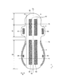
- FIG. 1 is a plan view of the absorbent article in one embodiment.
- FIG. 2 is a plan view of the absorbent article as seen from the side opposite to FIG.
- FIG. 3 is a cross-sectional view of the absorbent article taken along line 3A-3A in FIG.
- the absorbent article 1 has a front-rear direction L, a width direction W, and a thickness direction T.
- the front-rear direction L is a direction extending from the front side (abdomen side) of the wearer to the rear side (back side), or a direction extending from the rear side of the wearer to the front side.
- the width direction W is a direction orthogonal to the front-rear direction L.
- the thickness direction T is a direction extending from the wearer's skin side T1 to the non-skin side T2, and is a direction orthogonal to the front-rear direction L and the width direction W.
- the skin side T1 corresponds to the side facing the wearer's skin during use.
- the non-skin surface side T2 corresponds to the side opposite to the skin surface side T1, that is, the side facing away from the wearer's skin during use.
- the absorbent article 1 has an excretion opening contact area S1, a front side area S2, and a rear side area S3.
- the excretion opening contact area S1 is an area facing the excretion opening (for example, vaginal opening) of the wearer.
- the excretion opening contact area S1 is located in the crotch part of the underwear. That is, the excretion opening contact area is an area disposed between the wearer's crotch, that is, between the wearer's legs.
- the front side area S2 is located in front of the excretory opening contact area S1.
- the front edge of the front region S2 defines the front edge of the absorbent article 1.
- the rear side region S3 is located behind the excretory opening contact region S1.
- the rear edge of the rear side region S3 defines the rear edge of the absorbent article 1.
- the length in the front-rear direction L of the rear side region S3 may be longer than the length in the front-rear direction L of the excretory opening contact region S1.
- a wing 3 described later may be provided in the excretion opening contact area S1. Further, a hip flap 4 swelled outward in the width direction W may be provided in the rear side region S3.
- the front edge of the wing 3 is defined by the root of the wing 3, and corresponds to the portion located on the front side of the two portions that are recessed most in the width direction W.
- the front edge of the wing 3 may define a boundary between the excretory opening contact area S1 and the front side area S2.
- the rear edge of the wing 3 is defined by the root of the wing 3, and corresponds to a portion located on the rear side of the two portions that are recessed most in the width direction W.
- the rear edge of the wing 3 may be located between the excretory opening contact area S1 and the rear side area S3.
- a region between the front end edge of the wing 3 and the rear end edge of the wing 3 in the front-rear direction L is referred to as a “wing region”.
- the excretion opening contact area S1 is substantially the same area as the wing area. Therefore, it should be noted that in the present specification, the term “excretion opening contact area S1” can be read as “wing area”.
- the absorbent article 1 has a skin sheet 10, a non-skin sheet 20, and an absorber 30.
- the skin surface sheet 10 is provided on the skin surface side T ⁇ b> 1 from the absorbent body 30.
- the non-skin surface sheet 20 is provided on the non-skin surface side T2 with respect to the absorber 30.
- the absorber 30 is provided between the skin sheet 10 and the non-skin sheet 20.
- the skin sheet 10 may have a top sheet 11, a side sheet 12, and a second sheet 13.
- the top sheet 11 is a liquid-permeable sheet that transmits liquid such as body fluid.
- the top sheet 11 covers the central portion of the absorber 30 in the width direction W.
- the topsheet 11 may extend in the front-rear direction L from the front side region S2 to the rear side region S3.
- the top sheet 11 is made of any sheet-like material having a structure that allows liquid to permeate, such as a nonwoven fabric, a woven fabric, a perforated plastic sheet, and a mesh sheet. Either natural fibers or chemical fibers can be used as the woven or non-woven material.
- the side sheet 12 covers the outer edge of the top sheet 11 in the width direction W, and extends outward in the width direction W from the top sheet 11.
- the absorbent article 1 has the side sheet 12
- the absorbent article 1 does not need to have the side sheet 12.
- the top sheet 11 may cover the entire absorber 30.
- the side sheet 12 can be made of the same material as the top sheet 11. However, in order to prevent the body fluid adhering to the top sheet 11 from getting over the side sheet 12 and leaking outside the absorbent article 1 in the width direction W, the side sheet 12 has hydrophobicity or water repellency. It is preferable to have.
- the side seat 12 may be disposed on the outer edge of the absorbent body 30 in the width direction W, the wing 3 and the hip flap 4.
- the second sheet 13 is provided between the top sheet 11 and the absorber 30 at least in a non-joining region 46 described later.
- the second seat 13 may extend in the front-rear direction L from the front side region S2 to the rear side region S3. Instead, the second sheet 13 may be provided only in the non-joining region 46 described later.
- the second sheet 13 is preferably narrower in the width direction W than the width of the absorbent core 31 described later.
- the second sheet 13 is a liquid-permeable sheet that transmits liquid such as body fluid.
- the hydrophilicity of the second sheet 13 is higher than the hydrophilicity of the top sheet 11.
- the hydrophilicity of the second sheet 13 only needs to be higher than the hydrophilicity of the topsheet 11 at least in the non-bonding region 46 described later.
- the second sheet 13 can be made of the same material as the top sheet 11.
- the non-skin surface sheet 20 is a liquid-impermeable sheet.
- the non-skin sheet 20 may be a polyethylene sheet, a laminated nonwoven fabric mainly composed of polypropylene, a breathable resin film, a spunbond, or a sheet in which a breathable resin film is bonded to a nonwoven fabric such as spunlace. it can.
- the absorber 30 is disposed at least in the excretory opening contact area S1 and the rear side area S3. Moreover, the absorber 30 may extend from the excretory opening contact area S1 to the front side area S2.
- the absorber 30 includes an absorbent core 31 including an absorbent material that absorbs liquid, and a core wrap 32 that wraps the absorbent core 31.
- the core wrap 32 only needs to cover the absorbent core 31 at least on the skin surface side of the absorbent core 31.
- the core wrap 32 may include a sheet disposed on the skin surface side with respect to the absorbent core 31 and a sheet disposed on the non-skin surface side with respect to the absorbent core 31.
- the skin-side sheet and the non-skin-side sheet constituting the core wrap 32 may be composed of the same sheet.
- the absorbent material constituting the absorbent core 31 can be formed from, for example, hydrophilic fibers, pulp, and superabsorbent polymer (SAP).
- the core wrap 32 can be comprised, for example from a nonwoven fabric or a tissue sheet.
- the absorber 30 may not have the core wrap 31.
- the absorbent core 31 only needs to be covered with the skin sheet 10 and the non-skin sheet 20.
- the absorbent article 1 has the wing 3 and the hip flap 4.
- the wing 3 and the hip flap 4 extend outward in the width direction W from the outer edge of the absorbent core 31 in the excretory opening contact region S1.
- the wing 3 and the hip flap 4 may be configured by stacking the side sheet 12 and the non-skin sheet 20.
- the wing 3 is configured to be folded back to the non-skin surface sheet 20 side.
- the wing 3 is folded back to the non-skin surface side of the crotch portion of the underwear during use.
- the hip flap 4 is located on the rear side of the wing 3 and is provided in the rear side region S3.
- the hip flap 4 is not folded back during use, and is disposed between the underwear and the wearer's buttocks.
- the hip flap 4 is not provided with an absorbent material.
- the hip flap 4 may be provided with an absorbent material.
- FIG. 4 is a plan view of the absorber 30 in one embodiment.
- the absorber 30 has the middle-high part 33 at least in the excretion opening contact area S1.
- the middle / high part 33 may extend from the excretory opening contact area S1 to the front side area S2.
- the middle / high portion 33 is disposed across the center line CL in the excretion opening contact region S1.
- the middle-high portion 33 means a region where the thickness of the absorbent core 31 is thicker than the thickness of the absorbent core 31 in the region around the middle-high portion 33.
- the basis weight of the absorbent material of the middle-high portion 33 may be higher than the basis weight of the absorbent core 31 in a region other than the middle-high portion 33 in the excretory opening contact region S1.
- the middle-high portion 33 may be adjacent to a first low weight area 41 described later.
- the absorption core 31 on the rear side of the first low weight area 41 is thinner than the thickness of the middle-high portion 33. More preferably, the absorption core 31 of the entire rear side region S3 is thinner than the thickness of the middle-high portion 33.
- the middle-high part 33 has the thickest highest part and the inclined part connected to the highest part.
- the inclined portion may be disposed between the highest portion and a front pressing portion described later, and between the highest portion and the first low weight area 41.
- the absorber 30 may have a first low weight area 41, a second low weight area 42, and a third low weight area 43.
- the “low weight area” means a region composed of the absorbent core 31 having a lower basis weight than the surrounding absorbent core 31 or a region not having the absorbent core 31.
- the “low weight area” is a concept including an area where the weight of the absorbent core 31 is zero.
- the weight of the absorbent core 31 in the low weight areas 41 to 43 is preferably 150 g / m 2 or less, more preferably 100 g / m 2 or less. Further, the weight of the absorbent core 31 in the low weight areas 41 to 43 is more preferably substantially 0 g / m 2 . Further, the basis weight of the absorbent core 31 in the low basis weight areas 41 to 43 is preferably 60% or less, and 50% or less of the basis weight of the absorption cores (excluding middle and high portions) around the low basis weight areas 41 to 43. It is more preferable.
- the core wrap 32 may wrap the entire absorbent core 31 across the low-weight area. In this case, even if the absorbent core 31 is divided into a plurality of regions, the absorbent body 30 is integrally formed by the core wrap 32.
- the first low-weight area 41, the second low-weight area 42, and the third low-weight area 43 are boundaries where the rigidity of the absorber 30 changes. Therefore, the first low weight area 41, the second low weight area 42, and the third low weight area 43 correspond to areas where the absorber 30 is easily deformed.
- the first low weight area 41 extends in the width direction W between the excretory opening contact area S1 and the rear side area S3.
- the first low weight area 41 may extend linearly along the width direction W or may extend along a curve along the width direction W.
- the first low weight area 41 may be provided behind the center of the wing 3 in the front-rear direction L and on the front side of the rear edge of the absorber 30.
- the first low weight area 41 may be provided across the rear end edge of the wing 3 in the front-rear direction L.
- the first low weight area 41 has a curved shape in which the center in the width direction W of the first low weight area 41 protrudes rearward. More specifically, the center of the first low weight area 41 in the width direction W is located behind the outer edge of the first low weight area 41.
- the length in the front-rear direction L of the first low weight area 41 may be constant or may not be constant.
- the length of the first low weight area 41 in the width direction W is 25 mm or more. Thereby, it can suppress that the motion of the absorber 30 in the excretion opening
- the front edge of the first low weight area 41 may define the rear edge of the excretory opening contact area S1, and the rear edge of the first low weight area 41 defines the front edge of the rear area S3. It may be specified.
- the length of the first low weight area 41 in the front-rear direction L is preferably 10 mm or more and 50 mm or less, more preferably 10 mm or more and 30 mm or less, at the position of the center line CL of the absorbent article 1.
- the second low weight area 42 extends in the front-rear direction L along the center line CL of the absorbent article in the rear side area S3.
- the second low weight area 42 may extend linearly in the front-rear direction L.
- the second low weight area 42 is preferably connected to the first low weight area 41.
- the rear end edge of the second low weight area 42 may be located behind the center of the rear side area S3 in the front-rear direction. Further, the rear end edge of the second low weight area 42 may be located on the rear side of the position P1 of the maximum width of the hip flap 4.
- the length in the front-rear direction L of the second low weight area 42 is preferably 120 mm or more, and more preferably 150 mm or more. Preferably, the length of the second low weight area 42 in the width direction W is not less than 1 mm and not more than 15 mm.
- a groove (crack) between the hips exists in a region from the back to the caudal bone from the back of the perineum.
- the second low weight area 42 is located in the area of the wearer's rupture.
- the third low weight area 43 extends outward in the width direction W from the second low weight area 42 in the rear side area S3.
- the third low weight area 43 may be connected to the second low weight area 42.
- the front edge line of the third low weight area 43 may extend substantially parallel to the width direction W inside the width direction W. Further, the front edge line of the third low weight area 43 may protrude forward on the outer side in the width direction W.
- the rear edge line of the third low weight area 43 may be inclined forward as it goes from the inner side to the outer side in the width direction W.
- the outer edge of the third low weight area 43 in the width direction W is located inside the outer edge of the absorbent core 31 in the rear area S3.
- a plurality of third low weight areas 43 may be provided at intervals in the front-rear direction L.
- the absorbent article 1 includes crimping portions 51, 52, and 53 in which a sheet of the core wrap 32 on the skin surface side of the absorbent core 31 and a sheet of the core wrap 32 on the non-skin surface side of the absorbent core 31 are crimped to each other. (See FIG. 4).
- the first crimping part 51 extends in the width direction W along the first low weight area 41.
- the width of the first crimping part 51 in the front-rear direction L is preferably smaller than the width of the first low weight area 41 in the front-rear direction L.
- compression-bonding part 51 is continuously extended from the one end of the absorber 30 along the width direction W to the other end.
- the second crimping part 52 extends in the front-rear direction L along the second low weight area 42.
- the width of the second pressure-bonding portion 52 in the width direction W is preferably smaller than the width of the second low weight area 42 in the width direction W.
- the second crimping part 52 may be connected to the first crimping part 51.
- the third crimping portion 53 extends along the third low weight area 43.
- the width of the third pressure-bonding portion 53 in the front-rear direction L is preferably smaller than the width of the third low weight area 43 in the front-rear direction L.
- the third crimping part 53 may be connected to the second crimping part 52.
- the first pressure-bonding part 51, the second pressure-bonding part 52, and / or the third pressure-bonding part 53 are not formed on the skin sheet 10. More specifically, the first crimping part 51, the second crimping part 52, and / or the third crimping part 53 may be formed by crimping only the core wrap 32 or only the absorbent core 31 and the core wrap 32. preferable. When the absorbent core is present in the low weight areas 41, 42, 43, the crimping parts 51, 52, 53 may be parts where the absorbent cores of the low weight areas 41, 42, 43 and the core wrap 32 are crimped together. .
- the crimping parts 51, 52, 53 may be parts where only the core wrap 32 is crimped. In this case, the absorbent core 31 is divided from each other with the low weight areas 41, 42, 43 and the crimping parts 51, 52, 53 as boundaries.
- the crimping parts 51, 52 and 53 can be formed by embossing.
- compression-bonding parts 51, 52, and 53 are covered with the skin sheet 10, they cannot be visually recognized from the outside or are difficult to visually recognize.
- the first pressure-bonding part 51, the second pressure-bonding part 52 and / or the third pressure-bonding part 53 may be formed on the skin sheet 10 and / or the non-skin sheet 20.
- Non-joining region between the top sheet and the absorber The skin sheet 10 is not joined to a member provided on the non-skin surface side of the skin sheet 10 in the first low weight area 41. It has the joining area
- region 46 (refer FIG.1 and FIG.3). More specifically, the skin sheet 10 is not joined to the core wrap 32 in the non-joined region 46.
- the non-bonding region 46 is indicated by a region surrounded by a broken line in FIG.
- the non-bonding region 46 may extend at least from one end to the other end of the first low weight area 41 in the width direction W. Instead, the non-joining region 46 may not extend to both ends of the first low weight area 41 in the width direction W.
- the non-joining area 46 may extend from at least the first low weight area 41 to the third low weight area 43 closest to the first low weight area 41 among the plurality of third low weight areas 43. Accordingly, the skin sheet 10 can be lifted from the absorbent body 30 in the first low weight area 41 and the rear area.
- Pressing part Absorbent article 1 has a pressing part formed by compressing at least absorption core 31 in thickness direction T.
- This pressing part may have the front side pressing part 81, the longitudinal pressing part 82, and a pair of rear side pressing parts 84 (refer FIG.1 and FIG.4).
- the front pressing part 81 is provided at least in the excretion opening contact area S1.
- the front side pressing part 81 may extend from the excretion opening contact area S1 to the front side area S2.
- the front pressing part 81 may be formed by compressing the topsheet 11, the absorbent core 31, and the core wrap 32 in the thickness direction T.
- the front side compression part 81 has a section along the front-rear direction L provided on both sides in the width direction W of the middle-high part 33.
- the front side compressed portion 81 may define a side edge in the width direction W of the middle-high portion 33.
- the front pressing part 81 is bent toward the width direction W in the vicinity of the front end edge of the absorbent core 31, and is continuously connected in a U shape. Instead of this, the front pressing part 81 may be provided separately on both sides in the width direction W of the middle-high part 33. That is, the pair of front pressing parts 81 may be provided separately in a form separated from each other.
- the longitudinal pressing part 82 is provided on both sides of the center line CL, more specifically, the second low weight area 42 in the rear side area S3.
- the longitudinal pressing part 82 may be formed by the absorber 30 and the surface sheet 11 being compressed in the thickness direction.
- the longitudinal pressing part 82 extends along the front-rear direction L.
- the longitudinal pressing portion 82 may extend linearly in the front-rear direction L, or may extend in a curved manner inclined with respect to the front-rear direction L.
- the longitudinal pressing part 82 may be formed in front of the position P1 of the maximum width of the hip flap 4.
- the pair of rear side compression parts 84 is provided on both sides of the center line CL in the rear side region S3.
- the rear side pressing part 84 may be formed by the absorber 30 and the surface sheet 11 being compressed in the thickness direction.
- a pair of rear side compression parts 84 are spaced apart from each other with a center line CL passing through the center in the width direction W of the absorbent article.
- the pair of rear side compressed parts 84 may be located on the rear side of the position P1 of the maximum width of the hip flap 4.
- the absorbent article 1 includes a first pressing unit 85 and a second pressing unit formed by pressing at least two of the sheets constituting the skin sheet 10 and the non-skin sheet 20 in the thickness direction T. 87 and the 3rd pressing part 86 may be included (refer FIG. 1). The first pressing part 85, the second pressing part 87 and the third pressing part 86 may be formed along the outer edge of the hip flap 4.
- the absorbent article 1 may have a pressing part 88 formed by pressing the skin sheet 10 at least in the first low weight area 41. It is preferable that the pressing part 88 is formed only in the skin sheet 10 (refer FIG. 1).
- the compressed portion 88 may slightly reach the front side slightly beyond the first low weight area 41, but is preferably present on the rear side than the middle-high portion 33.
- the pressing part 88 may extend from at least the first low weight area 41 to the third low weight area 43 closest to the first low weight area 41 among the plurality of third low weight areas 43.
- the compressed portion 88 may be formed in a region that is substantially equivalent to the non-joining region 46 or a region that is narrower than the non-joining region 46.
- the compressed portion 88 is preferably formed continuously in the front-rear direction L at least in the first low weight area 41.
- the pressing part 88 continues in the front-back direction L, it is not necessary to be formed linearly.
- the compressed portion 88 may have a zigzag shape in the front-rear direction L. It replaces with this, and the pressing part 88 may be continuously formed in the front-back direction L at least in the 1st low weight area
- the pressing part 88 is formed in a lattice shape as shown in FIG. Specifically, the compressed portion 88 has a plurality of first linear patterns inclined with respect to the front-rear direction and a plurality of second linear patterns inclined with respect to the front-rear direction and the first linear pattern. Good. It is preferable that the pressing part 88 is provided in an area narrower than the area of the second sheet 13.
- the absorbent article 1 includes a first main body adhesive region 61, a second main body adhesive region 62, and a wing provided with an adhesive for fastening the absorbent article 1 to the underwear S. It has an adhesive region 63 and a hip flap adhesive region 64. These adhesive regions 61 to 64 are provided on the non-skin surface side of the non-skin sheet 20. The adhesive regions 61 to 64 may be covered with a release sheet in a state before use. The release sheet prevents deterioration of the adhesive in the adhesive regions 61 to 64 before use. The release sheet is removed by the wearer during use.
- the first main body adhesive region 61 is disposed in front of the second main body adhesive region 62.
- the first main body adhesive region 61 and the second main body adhesive region 62 extend in the front-rear direction L.
- the first main body adhesive region 61 is disposed away from the second main body adhesive region 62 in the front-rear direction L.
- the first main body adhesive region 61 may be disposed on the front side of the first low weight area 41 and straddling the excretory opening contact region S1 and the front side region S2.
- the second main body adhesive region 62 is disposed in the rear region S3 on the rear side of the first low weight area 41.
- region 62 are not provided on the centerline CL.
- the wing adhesive region 63 is provided in the wing 3.
- the hip flap adhesive region 64 is provided in the hip flap 4.
- the first low weight area 41 is preferably arranged in a region that does not overlap with the adhesive regions 61 to 64 in the thickness direction T. More specifically, the first low weight area 41 is provided in a region between the first main body adhesive region 61 and the second main body adhesive region 62.
- the second low weight area 42 is preferably arranged in a region that does not overlap with the adhesive regions 61 to 64 in the thickness direction T. More specifically, the second low weight area 42 is provided between the plurality of second main body adhesive areas 62.
- the pair of longitudinal pressing portions 82 is provided in a region overlapping the second main body adhesive region 62.
- FIG. 5 is a perspective view of the absorbent article in use.
- 6 is a schematic cross-sectional view of the absorbent article in use, taken along line 6A-6A in FIG. 7 is a schematic cross-sectional view of the absorbent article in use, taken along line 7A-7A in FIG. 8 is a schematic cross-sectional view of the absorbent article in use, taken along line 3A-3A in FIG.
- a line indicating the shape of the wearer's body is indicated by a two-dot chain line.
- the absorbent article 1 When the absorbent article 1 as a sanitary napkin is worn, the absorbent article 1 is fixed to the underwear S.
- the excretion opening contact area S1 of the absorbent article 1 is sandwiched between both legs of the wearer and receives a force from the outside in the width direction W toward the inside in the width direction W.
- the cross-sectional shape of the wearer's body along the width direction W of the absorbent article 1 is different between the crotch vicinity and the buttocks vicinity. Specifically, the cross-sectional shape of the body in the vicinity of the wearer's crotch incision (around the vaginal opening where menstrual blood appears) is such that the large labia protrudes from the base of the large labia and protrudes toward the absorbent article 1 side. Convex shape. In the inseam area of the wearer, the excretion opening contact area S1 of the absorbent article is arranged to face.
- the absorption core 31 of the excretory opening contact area S1 in particular, the middle / high part 33 is arranged along the body, and leakage of body fluid in the crotch can be suppressed (see FIG. 6).
- the anus and rupture are located behind the perineum located behind the wearer's large labia.
- the cross-sectional shape of the body near the rear of the perineum is a shape in which the center in the width direction is recessed.
- the rear side area S3 of the absorbent article is disposed to face the wearer's buttocks.
- a second low weight area 42 extending in the front-rear direction L along the center line CL is formed in the rear side region S3, a second low weight area 42 extending in the front-rear direction L along the center line CL is formed. Therefore, the center of the rear region S3 in the width direction W easily protrudes toward the wearer's body due to the force from the outside to the inside of the absorbent article (see FIG. 7). Thereby, in back side region S3, the absorbent article 1 can deform
- the absorbent article 1 tends to change into different shapes according to the shape of the wearer's body in the excretory opening contact area S1 and the rear side area S3.
- the first low weight area 41 suppresses the influence of the deformation of the absorbent body 30 in the excretory opening contact area S1 on the deformation of the absorbent body 30 in the rear side area S3. That is, the first low weight area 41 makes it easy for the absorbent article to be independently deformed in the excretory opening contact area S1 and the rear area S3.
- sanitary napkins for night use are often used in a sleeping posture on the back. In the posture where the wearer is lying on his back, a gap is easily formed between the buttocks and the absorbent article 1.
- the rear area S3 of the absorbent article 1 may slightly move toward the excretory opening contact area S1 by the force from the buttocks. is there. Thereby, distortion arises in the front-back direction L in the vicinity of the region between the excretory opening contact region S1 and the rear side region S3. Due to this distortion, a gap may be generated between the absorbent article 1 and the buttocks in the vicinity of the region between the excretory opening contact region S1 and the rear side region S3.
- menstrual blood may be transmitted to the back side of the body and leak from behind the absorbent article.
- the wearer may feel that menstrual blood is transmitted through the body and feel anxious.
- the non-bonded region 46 of the skin sheet 10 is present at least at the first low weight area 41. Therefore, when the rear region S3 of the absorbent article moves toward the excretory opening contact region S1, the non-bonded region 46 of the skin sheet 10 protrudes toward the wearer's body (reference sign “FIG. 8”. 47 "). The protrusion 47 of the skin sheet 10 fills a gap between the wearer's body. Thereby, even if it is a sleeping posture, menstrual blood can be prevented from being transmitted to the back side through the body.
- FIG. 9 is a plan view of the absorbent article 1 folded along the folding line FL of FIG.
- FIG. 10 is a schematic side view of the absorbent article folded along the fold lines F1 to F3 in FIG.
- the absorbent article 1 has a front / rear fold line FL extending along the front / rear direction L, and a first fold line F1, a second fold line F2, and a third fold line F3 extending along the width direction W. Good.
- These folding lines FL, F1, F2, and F3 are lines for folding the absorbent article 1.
- the front and rear fold line FL may be provided outside the outer end of the absorber 30 in the width direction W. Further, the front-rear fold line FL may be provided on the inner side in the width direction W than the first pressing portion 85, the second pressing portion 87, and the third pressing portion 86.
- the first fold line F1 is provided on the rear side of the second fold line F2.
- the first fold line F ⁇ b> 1 may be provided in a region on the rear side of the maximum width P ⁇ b> 1 of the hip flap 4. Further, the first folding line F ⁇ b> 1 may be provided between the longitudinal pressing portion 82 and the rear pressing portion 84 in the front-rear direction L.
- the first fold line F ⁇ b> 1 preferably passes through the third low weight area 43. In the absorbent article 1 in which the length of the rear side region S3 in the front-rear direction L is relatively short, the first fold line F1 may not be provided.
- the second fold line F2 is provided between the first fold line F1 and the third fold line F3 in the front-rear direction L.
- the second fold line F ⁇ b> 2 passes through an area on the rear side of the first low weight area 41 in the non-bonded area 46.
- the 2nd folding line F2 may be arrange
- the third fold line F3 is provided in front of the second fold line F2.
- the third fold line F3 may be provided on the front side of the highest part of the middle-high part 33. More specifically, it is preferable that the third fold line F ⁇ b> 3 avoids the highest portion of the middle-high portion 33 and passes through an inclined portion connected to the highest portion of the middle-high portion 33.
- the third fold line F3 may be provided in the front side area S2.
- the absorbent article 1 is folded inward from the front / rear fold line FL so that the non-skin side is exposed to the outside (see FIG. 9). From the state shown in FIG. 9, the absorbent article 1 is preferably folded in the order of the first fold line F1, the second fold line F2, and the third fold line F3 (see FIG. 10).
- the rear edge 92 of the absorbent article is located inside the absorbent article.
- the front edge 91 of the absorbent article is located outside the absorbent article.
- the first fold F1 is located inside the folded absorbent article 1.
- the second fold line F2 and the third fold line F3 are located outside the folded absorbent article 1.
- the absorber 30 includes a first low weight area 41 extending in the width direction W between the excretory opening contact area S1 and the rear side area S3, and the rear side area S3.
- the second low weight area 42 extends in the front-rear direction L along the center line CL.
- the second low weight area 42 is connected to the first low weight area 41.
- the absorber 30 has a first low basis weight extending in the width direction W on the rear side of the center of the wing 3 in the front-rear direction L and on the front side of the center of the rear side region S3 in the front-rear direction L.
- a region 41 and a second low-weight area 42 extending to the rear side from the center of the rear-side area S3 in the front-rear direction L along the center line CL in the rear-side area S3.
- the first low weight area 41 is connected.
- the rear side region S3 of the absorbent article is arranged directly below the wearer's buttocks, that is, between the buttocks and the floor. Since the second low weight area 42 formed in the rear side area S3 has a relatively low rigidity, the discomfort given to the wearer is small. Further, the absorbent material constituting the absorbent core 31 by the first low weight area 41 and the second low weight area 42 is the excretory opening contact area S1 (or wing area), the right side portion of the rear side area S3, and the rear It becomes difficult to move between the left side portion of the side region S3. Thereby, it can suppress that the absorption material which comprises the absorption core 31 concentrates locally by the operation
- the second low weight area 42 protrudes toward the wearer's skin side during wearing. Since the second low weight area 42 extends along the front-rear direction L in the rear side area S3, it is easy to fit along the wearer's crack. Further, as described above, the first low weight area 41 makes it easy for the absorbent article to be independently deformed in the excretory opening contact area S1 and the rear side area S3. That is, the absorbent article 1 fits in accordance with the shape of the body in both the excretory opening contact area S1 and the rear side area S3 by deforming independently in the excretion opening contact area S1 and the rear side area S3. obtain.
- the absorbent article becomes familiar with the wearer's body and can give a comfortable fit to the wearer.
- the first low weight area 41 continuously extends from one end of the absorber 30 to the other end along the width direction W.
- the absorption material which comprises the absorption core 31 becomes difficult to move more between the excretion opening
- the first low weight area 41 continuously extends from one end to the other end of the absorber 30, the absorption core of the excretory opening contact area S1 and the absorption core of the rear side area S3 are deformed independently of each other. It becomes easy to do.
- the absorption core of the excretory opening contact area S1 is more easily deformed according to the shape of the wearer's inseam, and the absorption core of the rear side area S3 is more deformed according to the shape of the wearer's buttocks (crack). It becomes easy. As a result, the absorbent article is more familiar with the wearer's body and can give a more comfortable fit to the wearer.
- the first low weight area 41 is curved in a convex shape toward the rear in a plan view.
- the portion of the first low weight area 41 that is convexly convex bulges convexly toward the rear together with the underwear and is pushed out in a direction away from the body.
- transformation of the absorbent article at the time of a supine posture can be absorbed. Therefore, the absorber 30 of the front side area S2 and the excretory opening contact area S1 is maintained in a shape that follows the roundness of the body, and as a result, the entire absorbent article is arranged along the roundness of the body.
- an absorptive article can adapt to a wearer's body more, and can give a more comfortable fit to a wearer.
- the absorbent body 30 has a pressure-bonding part in which a sheet closer to the skin surface than the absorbent core 31 and a sheet closer to the non-skin surface than the absorbent core 31 are bonded to each other.
- the sheet on the skin surface side from the absorbent core 31 is, for example, the core wrap 31 and / or the skin sheet 10.
- the sheet on the non-skin surface side of the absorbent core 31 is, for example, the core wrap 31 and / or the non-skin surface sheet 20.
- the pressure-bonding portion includes a first pressure-bonding portion 51 that extends along the first low-weighted area 41 and a second pressure-bonding portion 52 that extends along the second low-weighted area 42.
- the absorption core 31 is partitioned by the first crimping part 51 and the second crimping part 52 into an excretory opening contact area S1, a right side part of the rear side area S3, and a left side part of the rear side area S3.
- the absorption material which comprises the absorption core 31 can suppress moving between the excretion opening
- it can prevent that the absorbent material which comprises the absorption core 31 concentrates locally by the operation
- the wearer's discomfort can be alleviated while wearing the absorbent article. In particular, even when the wearer is sleeping, the wearer's discomfort can be alleviated, and a more comfortable fit can be given to the wearer.
- it has a core wrap 32 that covers the absorbent core 31 on the skin surface side at least with respect to the absorbent core 31, and a skin surface sheet 10 that is provided on the skin surface side with respect to the core wrap 32. At least one of the first pressure-bonding part 51 and the second pressure-bonding part 52 is not formed on the skin sheet 10. Thereby, the 1st crimping
- the first crimping part 51 extends from one end of the absorber 30 to the other end along the width direction W.
- the absorbent material constituting the absorbent core 31 becomes more difficult to pass through the first low weight area 41. That is, the absorbent material is less likely to move between the excretory opening contact area S1 and the rear side area S3. Therefore, it can suppress more that the absorption material which comprises the absorption core 31 concentrates locally by the operation
- a pair of longitudinal pressing parts 82 extending along the front-rear direction L are formed on both sides of the second low weight area 42. Since the pair of longitudinal compression portions 82 have relatively high rigidity, they serve as a base point for deformation of the absorbent core 31. The second low weight area 42 sandwiched between the pair of longitudinal pressing portions 82 is more likely to be raised on the wearer's body side. Thereby, the absorbent article which can be more familiar with a wearer's body and can give a more comfortable fit to a wearer can be provided.
- the first low weight area 41 and the second low weight area 42 are arranged in areas that do not overlap with the adhesive areas 61, 62, 63, 64.
- the first low weight area 41 and the second low weight area 42 can function as deformation base points. That is, the absorbent cores 31 adjacent to each other with the first low weight area 41 and the second low weight area 42 interposed therebetween can easily move independently of each other. Thereby, it becomes easy to fit the absorber 30 according to a wearer's inseam and the shape of a buttocks. Therefore, it is possible to provide an absorbent article that is more familiar with the wearer's body and can provide a more comfortable fit to the wearer.
- a pair of longitudinal squeezing portions 82 extending along the front-rear direction L are formed on both sides of the second low weight area 42, and the pair of longitudinal squeezing portions 82 and the adhesive region 62 It is provided in the overlapping area.
- a region where the pair of longitudinal pressing portions 82 is provided is fastened to the underwear.
- the absorber 30 has a third low weight area 43 extending outward from the second low weight area 42 in the width direction W in the rear side area S3.
- the third low weight area 43 forms a deformation base point extending along the width direction W. Since the absorbent core 31 in the rear side region S3 can be deformed with the third low weight area 43 as a base point, the absorbent article 1 can easily fit along the roundness along the front-rear direction L of the body. In particular, as shown in FIG. 7, when the second low weight area 42 protrudes along the fissure, it may be difficult to deform the rear side region S3 along the roundness along the front-rear direction L of the body. .
- the absorbent article which can be more familiar with a wearer's body and can give a more comfortable fit to a wearer can be provided.
- the absorber 30 is a middle-high portion 33 arranged across the center line CL in a region in front of the first low weight area 41, that is, in the excretory opening contact region S1 or the wing region.
- the middle / high portion 33 is thicker than the thickness of the absorber 30 around the middle / high portion.
- Excretion opening contact area S1 is located in a wearer's inseam.
- the relatively thick middle-high part 33 is easy to fit the shape of the wearer's crotch. Further, since the middle-high portion 33 has relatively high rigidity, only the region near the center line CL of the middle-high portion 33 is difficult to be locally deformed.
- the absorber 30 in the rear side area S3 is easily deformed so that the area in the vicinity of the center line CL protrudes toward the crack.
- the absorber 30 tends to be deformed into different shapes in the excretory opening contact area S1 and the rear side area S3.
- the absorber 30 is easily deformed independently from each other in the excretory opening contact region S1 and the rear region S3 by the first low weight area 41.
- an absorbent article can be made to fit more according to a wearer's body shape from a wearer's inseam to a crack. Therefore, it is possible to provide an absorbent article that is more familiar with the wearer's body and can provide a more comfortable fit to the wearer.
- the absorbent article has a hip flap 4 that swells outward in the width direction W in the rear side region S3. Since the hip flap 4 swells widely in the rear side region S3, a force from the outer side to the inner side in the width direction W is likely to be applied from the wearer's buttocks to the rear side region S3. Thereby, the 2nd low weight area 42 of back side field S3 becomes easier to protrude toward a wearer's explosion. As a result, the absorbent article 1 can be more easily fitted to the wearer in the rear side region S3 according to the shape of the buttocks.
- Absorbent article 10 Skin sheet 20: Non-skin sheet 30: Absorbent body 31: Absorbing core 32: Core wrap 33: Middle and high part 41: First low weight area 42: Second low weight area 43: Third low Weight area 51: 1st crimping part 52: 2nd crimping part 53: 3rd crimping part 61: 1st main body adhesion area 62: 2nd main body adhesion area 81: Front side compression part 82: Long side compression part 84: Rear side compression part L: front-rear direction W: width direction T: thickness direction S1: excretory opening contact area S2: front side area S3: rear side area CL: center line
Abstract
寝た姿勢において違和感を覚え難く、吸収体を臀裂に沿ってフィットさせ易い吸収性物品を提供する。吸収性物品(1)は、互いに直交する前後方向(L)及び幅方向(W)と、着用者の排泄口と対向する排泄口当接域(S1)と、排泄口当接域(S1)の後側に位置する後側域(S3)と、少なくとも排泄口当接域(S1)及び後側域(S3)に配置される吸収体(30)と、を有する。吸収体(30)は、排泄口当接域(S1)と後側域(S3)との間において幅方向(W)に延びる第1低目付領域(41)と、後側域(S3)において幅方向(W)の中心を結ぶ中心線(CL)に沿って前後方向(L)に延びる第2低目付領域(42)と、を有する。第2低目付領域(42)は、第1低目付領域(41)と繋がっている。
Description
本発明は、生理用ナプキン等の吸収性物品に関する。
経血やおりものなどを吸収するための生理用ナプキン、パンティーライナー、失禁パッド等の吸収性物品が知られている。吸収性物品のうち特に生理用ナプキンは、下着により着用者の体の方に押し当てられ、着用者の体にフィットされる(下記特許文献1)。生理用ナプキンのような吸収性物品は、表面シート、裏面シート及び吸収体を有する。吸収体は、表面シートと裏面シートとの間に設けられている。吸収体は、肌当接面側に凸状に突出する中高部を有している。中高部は、中高部以外の領域よりも厚みが厚い吸収体の一部分である。中高部は、吸収性物品の前方及び後方に、それぞれ別個に設けられている。前方の中高部と後方の中高部との間に、折り曲げ起点が設けられている。折り曲げ起点は、エンボス加工によって表面シートと吸収体とを互いに接合するための凹部である。
特許文献1に記載された吸収性物品では、前方の中高部は着用者の股下、すなわち膣口対向域に配置され、後方の中高部は着用者の股下よりも後ろ上方の臀部の割れ目に配置される。これにより、吸収体を臀部の臀裂に沿ってフィットさせている。
しかしながら、着用者が寝た姿勢において、後方の中高部は着用者の臀部の真下、すなわち臀部と床との間に配置される。中高部は特に剛性の高い領域を構成する。したがって、着用者は、寝た姿勢において、違和感を覚え易い。
そこで、寝た姿勢において違和感を覚え難く、吸収体を臀裂に沿ってフィットさせ易い吸収性物品が望まれる。
一態様に係る吸収性物品は、互いに直交する前後方向及び幅方向と、着用者の排泄口と対向する排泄口当接域と、前記排泄口当接域の後側に位置する後側域と、少なくとも前記排泄口当接域及び前記後側域に配置される吸収体と、を有し、前記吸収体は、前記排泄口当接域と前記後側域との間において前記幅方向に延びる第1の低目付領域と、前記後側域において前記幅方向の中心を結ぶ中心線に沿って前記前後方向に延びる第2の低目付領域と、を有しており、前記第2の低目付領域は、前記第1の低目付領域と繋がっている。
ここで、「低目付領域」は、その周囲の吸収コアよりも低い目付を有する吸収コアからなる領域、又は吸収コアを有していない領域(すなわち目付が零の領域)を意味するものとする。
別の態様に係る吸収性物品は、互いに直交する前後方向及び幅方向と、吸収体と、前記幅方向における前記吸収体の外側縁よりも前記幅方向の外側に延出し、使用時に折り返し可能なウイングと、前記前後方向における前記ウイングの前端縁と前記ウイングの後端縁との間の領域であるウイング域と、前記ウイング域よりも後側に位置する後側域と、を有し、前記吸収体は、前記前後方向における前記ウイングの中心よりも後側、かつ前記前後方向における前記後側域の中心よりも前側において、前記幅方向に延びる第1低目付領域と、前記後側域において前記幅方向の中心を結ぶ中心線に沿って前記前後方向における前記後側域の中心よりも後側まで延びる第2低目付領域と、を有しており、前記第2低目付領域は、前記第1低目付領域と繋がっている。
以下、図面を参照して、実施形態に係る吸収性物品ついて説明する。吸収性物品は、パンティーライナー(おりものシート)や生理用ナプキンや失禁パッド等の任意の吸収性物品であってよい。以下の実施形態では、吸収性物品の一例として使い捨ての生理用ナプキンについて説明する。
なお、以下の図面の記載において、同一又は類似の部分には、同一又は類似の符号を付している。ただし、図面は模式的なものであり、各寸法の比率等は現実のものとは異なる場合があることに留意すべきである。したがって、具体的な寸法等は、以下の説明を参酌して判断すべきである。また、図面相互間においても互いの寸法の関係や比率が異なる部分が含まれ得る。
(1)吸収性物品の全体的構成
図1は、一実施形態における吸収性物品の平面図である。図2は、図1とは反対側から見た吸収性物品の平面図である。図3は、図1の3A-3A線に沿った吸収性物品の断面図である。
図1は、一実施形態における吸収性物品の平面図である。図2は、図1とは反対側から見た吸収性物品の平面図である。図3は、図1の3A-3A線に沿った吸収性物品の断面図である。
吸収性物品1は、前後方向Lと幅方向Wと厚み方向Tとを有する。前後方向Lは、着用者の前側(腹側)から後側(背側)に延びる方向、又は着用者の後側から前側に延びる方向である。幅方向Wは、前後方向Lと直交する方向である。厚み方向Tは、着用者の肌面側T1から非肌面側T2へ延びる方向であり、前後方向L及び幅方向Wに直交する方向である。肌面側T1は、使用時に、着用者の肌に面する側に相当する。非肌面側T2は、使用時に、肌面側T1とは反対側、すなわち着用者の肌とは反対に向けられる側に相当する。
吸収性物品1は、排泄口当接域S1、前側域S2及び後側域S3を有する。排泄口当接域S1は、着用者の排泄口(例えば膣口)に対向する領域である。吸収性物品が下着に装着されたときに、排泄口当接域S1は、下着の股下部に位置する。つまり、排泄口当接域は、着用者の股下、すなわち着用者の両足の間に配置される領域である。
前側域S2は、排泄口当接域S1よりも前側に位置する。前側域S2の前端縁は吸収性物品1の前端縁を規定する。後側域S3は、排泄口当接域S1よりも後側に位置する。後側域S3の後端縁は吸収性物品1の後端縁を規定する。後側域S3の前後方向Lの長さは、排泄口当接域S1の前後方向Lの長さよりも長くなっていてよい。
排泄口当接域S1には、後述するウイング3が設けられていてよい。また、後側域S3には、幅方向Wの外側に膨らんだヒップフラップ4が設けられていてよい。
ウイング3の前端縁は、ウイング3の付け根によって規定されており、最も幅方向Wの内側に窪んだ2つの部分のうち、前側に位置する部分に相当する。ウイング3の前端縁は、排泄口当接域S1と前側域S2との境界を規定していてもよい。ウイング3の後端縁は、ウイング3の付け根によって規定されており、最も幅方向Wの内側に窪んだ2つの部分のうち、後側に位置する部分に相当する。ウイング3の後端縁は、排泄口当接域S1と後側域S3との間に位置していてよい。ここで、前後方向Lにおけるウイング3の前端縁とウイング3の後端縁との間の領域を「ウイング域」と称する。ウイングを有する吸収性物品では、排泄口当接域S1は、ウイング域と実質的に同じ領域となる。したがって、本明細書において、「排泄口当接域S1」との語は、「ウイング域」と読み替えることができることに留意すべきである。
吸収性物品1は、肌面シート10、非肌面シート20及び吸収体30を有する。肌面シート10は、吸収体30よりも肌面側T1に設けられる。非肌面シート20は、吸収体30よりも非肌面側T2に設けられる。吸収体30は、肌面シート10と非肌面シート20との間に設けられる。
肌面シート10は、表面シート11、サイドシート12及びセカンドシート13を有していてよい。表面シート11は、体液等の液体を透過する液透過性のシートである。表面シート11は、幅方向Wにおける吸収体30の中央部を覆う。表面シート11は、前後方向Lに前側域S2から後側域S3まで延びていてよい。
表面シート11は、不織布、織布、有孔プラスチックシート、メッシュシート等、液体を透過する構造を有する任意のシート状の材料から構成される。織布や不織布の素材としては、天然繊維、化学繊維のいずれも使用できる。
サイドシート12は、幅方向Wにおける表面シート11の外側縁を覆い、表面シート11よりも幅方向Wの外側へ延びている。なお、本実施形態では、吸収性物品1はサイドシート12を有しているが、吸収性物品1はサイドシート12を有していなくてもよい。この場合、表面シート11は吸収体30全体を覆っていてよい。
サイドシート12は、表面シート11と同様の材料から構成することができる。ただし、表面シート11に付着した体液が、サイドシート12を乗り越えて、幅方向Wにおいて吸収性物品1の外側へ漏れ出すことを防止するためには、サイドシート12は、疎水性又は撥水性を有することが好ましい。サイドシート12は、幅方向Wにおける吸収体30の外側縁、ウイング3及びヒップフラップ4に配置されていてよい。
セカンドシート13は、少なくとも後述する非接合領域46において、表面シート11と吸収体30との間に設けられている。セカンドシート13は、前後方向Lに前側域S2から後側域S3まで延びていてよい。この代わりに、セカンドシート13は、後述する非接合領域46にのみ設けられていてもよい。また、セカンドシート13は、幅方向Wにおいて、後述の吸収コア31の幅よりも狭いことが好ましい。
セカンドシート13は、体液等の液体を透過する液透過性のシートである。好ましくは、セカンドシート13の親水度は表面シート11の親水度よりも高い。具体的には、セカンドシート13の親水度は、少なくとも後述する非接合領域46において、表面シート11の親水度よりも高ければよい。セカンドシート13は、表面シート11と同様の材料から構成することができる。
非肌面シート20は、液不透過性のシートである。非肌面シート20は、ポリエチレンシート、ポリプロピレン等を主体としたラミネート不織布、通気性の樹脂フィルム、スパンボンド、又はスパンレース等の不織布に通気性の樹脂フィルムが接合されたシートなどを用いることができる。
吸収体30は、少なくとも排泄口当接域S1及び後側域S3に配置される。また、吸収体30は、排泄口当接域S1から前側域S2まで延びていてもよい。吸収体30は、液体を吸収する吸収材料を含む吸収コア31と、吸収コア31を包むコアラップ32と、を有する。コアラップ32は、少なくとも吸収コア31よりも肌面側で吸収コア31を覆っていればよい。具体的一例として、コアラップ32は、吸収コア31よりも肌面側に配置されるシートと、吸収コア31よりも非肌面側に配置されるシートと、を有していてよい。コアラップ32を構成する肌面側のシートと非肌面側のシートは、同一のシートから構成されていてもよい。吸収コア31を構成する吸収材料は、例えば、親水性繊維、パルプ及び高吸水性高分子(SAP)から形成できる。コアラップ32は、例えば不織布やティッシュシートから構成することができる。
上記実施形態の代わりに、吸収体30は、コアラップ31を有していなくてもよい。この場合、吸収コア31は、肌面シート10と非肌面シート20とによって覆われていればよい。
前述したように、吸収性物品1は、ウイング3及びヒップフラップ4を有する。ウイング3及びヒップフラップ4は、排泄口当接域S1における吸収コア31の外側縁よりも幅方向Wの外側に延出している。
ウイング3及びヒップフラップ4は、サイドシート12と非肌面シート20との積層によって構成されていてよい。ウイング3は、非肌面シート20側に折り返し可能に構成されている。ウイング3は、使用時に下着のクロッチ部の非肌面側に折り返される。
ヒップフラップ4は、ウイング3よりも後側に位置し、後側域S3に設けられている。ヒップフラップ4は、使用時に折り返されず、下着と着用者の臀部との間に配置される。本実施形態では、ヒップフラップ4には吸収材料が設けられていない。この代わりに、ヒップフラップ4には、吸収材料が設けられていてもよい。
(2)吸収体の詳細構成
次に、図1~図4を参照し、吸収体30の構成についてより具体的に説明する。図4は、一実施形態における吸収体30の平面図である。吸収体30は、少なくとも排泄口当接域S1に、中高部33を有する。中高部33は、排泄口当接域S1から前側域S2へ延びていてもよい。中高部33は、排泄口当接域S1において、中心線CLを跨いで配置されている。中高部33は、中高部33のまわりの領域の吸収コア31の厚みよりも吸収コア31の厚みが厚い領域を意味する。中高部33の吸収材料の目付は、排泄口当接域S1内の中高部33以外の領域における吸収コア31の目付よりも高くてもよい。中高部33は、後述する第1低目付領域41に隣接していてよい。好ましくは、第1低目付領域41の後側の吸収コア31は、中高部33の厚みよりも薄い。より好ましくは、後側域S3全体の吸収コア31は、中高部33の厚みよりも薄い。中高部33は、最も厚みが厚い最高部と、最高部へ繋がる傾斜部と、を有する。この傾斜部は、最高部と後述の前側圧搾部との間、及び最高部と第1低目付領域41との間に配置されていてよい。
次に、図1~図4を参照し、吸収体30の構成についてより具体的に説明する。図4は、一実施形態における吸収体30の平面図である。吸収体30は、少なくとも排泄口当接域S1に、中高部33を有する。中高部33は、排泄口当接域S1から前側域S2へ延びていてもよい。中高部33は、排泄口当接域S1において、中心線CLを跨いで配置されている。中高部33は、中高部33のまわりの領域の吸収コア31の厚みよりも吸収コア31の厚みが厚い領域を意味する。中高部33の吸収材料の目付は、排泄口当接域S1内の中高部33以外の領域における吸収コア31の目付よりも高くてもよい。中高部33は、後述する第1低目付領域41に隣接していてよい。好ましくは、第1低目付領域41の後側の吸収コア31は、中高部33の厚みよりも薄い。より好ましくは、後側域S3全体の吸収コア31は、中高部33の厚みよりも薄い。中高部33は、最も厚みが厚い最高部と、最高部へ繋がる傾斜部と、を有する。この傾斜部は、最高部と後述の前側圧搾部との間、及び最高部と第1低目付領域41との間に配置されていてよい。
吸収体30は、第1低目付領域41、第2低目付領域42及び第3低目付領域43を有していてよい。ここで、「低目付領域」は、その周囲の吸収コア31よりも低い目付を有する吸収コア31からなる領域、又は吸収コア31を有していない領域を意味する。このように、「低目付領域」は、吸収コア31の目付が零である領域を含む概念である。
低目付領域41~43における吸収コア31の目付は、好ましくは150g/m2以下、より好ましくは、100g/m2以下である。また、低目付領域41~43における吸収コア31の目付は、実質的に0g/m2であることがさらに好ましい。また、低目付領域41~43における吸収コア31の目付は、低目付領域41~43のまわりの吸収コア(中高部を除く)の目付の60%以下であることが好ましく、50%以下であることがより好ましい。
「低目付領域」が吸収コア31を有していない領域である場合でも、コアラップ32は、低目付領域を跨いで吸収コア31全体を包んでいてよい。この場合、吸収コア31が複数の領域に分断されていたとしても、吸収体30は、コアラップ32によって一体的に形成される。
第1低目付領域41、第2低目付領域42及び第3低目付領域43は、吸収体30の剛性が変化する境目となる。したがって、第1低目付領域41、第2低目付領域42及び第3低目付領域43は、吸収体30が変形し易い領域に相当する。
第1低目付領域41は、排泄口当接域S1と後側域S3との間において幅方向Wに延びている。第1低目付領域41は、幅方向Wに沿って直線的に延びていてもよいし、幅方向Wに沿って曲線的に延びていてもよい。
第1低目付領域41は、前後方向Lにおけるウイング3の中心よりも後側かつ吸収体30の後側縁よりも前側に設けられていてよい。第1低目付領域41は、前後方向Lにおいて、ウイング3の後端縁を跨ぐように設けられていてもよい。
本実施形態では、第1低目付領域41は、第1低目付領域41の幅方向Wの中央が後方に突出した曲線形状である。より詳細には、第1低目付領域41の幅方向Wの中心は、第1低目付領域41の外側縁よりも後方に位置する。第1低目付領域41の前後方向Lにおける長さは、一定であってもよいし、一定でなくてもよい。
好ましくは、幅方向Wにおける第1低目付領域41の長さは、25mm以上である。これにより、排泄口当接域S1における吸収体30の動きが、後側域S3に伝わることを抑制できる。より好ましくは、第1低目付領域41は、幅方向Wにおいて、吸収体30の一端から他端まで延びている。この場合、第1低目付領域41の前端縁が排泄口当接域S1の後端縁を規定していてもよく、第1低目付領域41の後端縁が後側域S3の前端縁を規定していてもよい。
前後方向Lにおける第1低目付領域41の長さは、吸収性物品1の中心線CLの位置で、好ましくは10mm以上かつ50mm以下であり、より好ましくは10mm以上かつ30mm以下である。
第2低目付領域42は、後側域S3において、吸収性物品の中心線CLに沿って前後方向Lに延びている。第2低目付領域42は、前後方向Lに直線的に延びていてよい。第2低目付領域42は、第1低目付領域41と繋がっていることが好ましい。
第2低目付領域42の後端縁は、前後方向における後側域S3の中心よりも後側に位置していてよい。また、第2低目付領域42の後端縁は、ヒップフラップ4の最大幅の位置P1よりも後側に位置していてもよい。第2低目付領域42の前後方向Lの長さは、120mm以上であることが好ましく、150mm以上であることがより好ましい。好ましくは、幅方向Wにおける第2低目付領域42の長さは、1mm以上かつ15mm以下である。着用者の身体の前後方向Lに沿った断面において、臀部間の溝(臀裂)は、会陰部よりも後方から尾てい骨に至る領域に存在する。吸収性物品の使用中に、第2低目付領域42は、着用者の臀裂の領域に配置される。
第3低目付領域43は、後側域S3において、第2低目付領域42から幅方向Wの外側に延びている。第3低目付領域43は、第2低目付領域42に繋がっていてよい。第3低目付領域43の前側の縁線は、幅方向Wの内側において、幅方向Wに実質的に平行に延びていてよい。また、第3低目付領域43の前側の縁線は、幅方向Wの外側において、前方に張り出していてよい。第3低目付領域43の後側の縁線は、幅方向Wの内側から外側に向かうにつれて、前方に傾斜していてよい。
幅方向Wにおける第3低目付領域43の外側縁は、後側域S3の吸収コア31の外側縁よりも内側に位置する。第3低目付領域43は、前後方向Lに間隔を空けて複数設けられていてよい。
吸収性物品1は、コアラップ32の、吸収コア31よりも肌面側のシートと、コアラップ32の、吸収コア31よりも非肌面側のシートとを、互いに圧着した圧着部51,52,53を有していてよい(図4参照)。
第1圧着部51は、第1低目付領域41に沿って幅方向Wに延びている。前後方向Lにおける第1圧着部51の幅は、前後方向Lにおける第1低目付領域41の幅よりも小さいことが好ましい。また、第1圧着部51は、幅方向Wに沿って、吸収体30の一端から他端まで連続的に延びていることが好ましい。
第2圧着部52は、第2低目付領域42に沿って前後方向Lに延びている。幅方向Wにおける第2圧着部52の幅は、幅方向Wにおける第2低目付領域42の幅よりも小さいことが好ましい。第2圧着部52は、第1圧着部51と繋がっていてよい。
第3圧着部53は、第3低目付領域43に沿って延びている。前後方向Lにおける第3圧着部53の幅は、前後方向Lにおける第3低目付領域43の幅よりも小さいことが好ましい。第3圧着部53は、第2圧着部52と繋がっていてよい。
第1圧着部51、第2圧着部52及び/又は第3圧着部53は、肌面シート10には形成されていないことが好ましい。より具体的には、第1圧着部51、第2圧着部52及び/又は第3圧着部53は、コアラップ32のみ、又は吸収コア31とコアラップ32のみを圧着することによって形成されていることが好ましい。低目付領域41,42,43に吸収コアが存在する場合、圧着部51,52,53は、低目付領域41,42,43の吸収コアとコアラップ32とを一緒に圧着した部分であってよい。低目付領域41,42,43に吸収コアが存在しない場合には、圧着部51,52,53は、コアラップ32のみを圧着した部分であってよい。この場合、吸収コア31は、低目付領域41,42,43及び圧着部51,52,53を境に、互いに分断される。圧着部51,52,53は、エンボス加工によって形成することができる。なお、圧着部51,52,53は、肌面シート10で覆われているため、外部から視認できない又は視認し難くなっている。なお、上記実施形態の代わりに、第1圧着部51、第2圧着部52及び/又は第3圧着部53は、肌面シート10及び/又は非肌面シート20に形成されていてもよい。
(3)表面シートと吸収体との間の非接合領域
肌面シート10は、第1低目付領域41において、肌面シート10よりも非肌面側に設けられた部材と接合されていない非接合領域46を有する(図1及び図3参照)。より具体的には、肌面シート10は、非接合領域46において、コアラップ32と接合されていない。非接合領域46は、図1において、破線で囲まれた領域によって示されている。
肌面シート10は、第1低目付領域41において、肌面シート10よりも非肌面側に設けられた部材と接合されていない非接合領域46を有する(図1及び図3参照)。より具体的には、肌面シート10は、非接合領域46において、コアラップ32と接合されていない。非接合領域46は、図1において、破線で囲まれた領域によって示されている。
非接合領域46は、少なくとも、幅方向Wにおける第1低目付領域41の一端から他端まで延びていてよい。この代わりに、非接合領域46は、幅方向Wにおいて第1低目付領域41の両端部まで延びていなくてもよい。非接合領域46は、少なくとも、第1低目付領域41から、複数の第3低目付領域43のうちの最も第1低目付領域41に近い第3低目付領域43まで延びていてよい。これにより、第1低目付領域41とその後側の領域において、肌面シート10は、吸収体30から浮き上がることができるようになる。
(4)圧搾部
吸収性物品1は、少なくとも吸収コア31が厚み方向Tに圧縮されることによって形成された圧搾部を有する。この圧搾部は、前側圧搾部81と、長手圧搾部82と、一対の後側圧搾部84と、を有していてよい(図1及び図4参照)。
吸収性物品1は、少なくとも吸収コア31が厚み方向Tに圧縮されることによって形成された圧搾部を有する。この圧搾部は、前側圧搾部81と、長手圧搾部82と、一対の後側圧搾部84と、を有していてよい(図1及び図4参照)。
前側圧搾部81は、少なくとも排泄口当接域S1に設けられている。前側圧搾部81は、排泄口当接域S1から前側域S2へ延びていてもよい。前側圧搾部81は、表面シート11と吸収コア31とコアラップ32とが厚み方向Tに圧縮されることによって形成されていてよい。前側圧搾部81は、中高部33の幅方向W両側に設けられた前後方向Lに沿った区間を有する。前側圧搾部81は、中高部33の幅方向Wにおける側縁を規定していてよい。
前側圧搾部81は、吸収コア31の前端縁付近で幅方向Wに向かって曲がっており、U字型に連続的に繋がっている。この代わりに、前側圧搾部81は、中高部33の幅方向W両側に、別個に設けられていてもよい。すなわち、一対の前側圧搾部81が、互いに分断された形態で、別個に設けられていてもよい。
長手圧搾部82は、後側域S3で、中心線CL、より具体的には第2低目付領域42を挟んで両側に設けられている。長手圧搾部82は、吸収体30と表面シート11とが厚み方向に圧縮されることによって形成されていてよい。
長手圧搾部82は、前後方向Lに沿って延びている。長手圧搾部82は、前後方向Lに直線的に延びていてもよいし、前後方向Lに対して傾斜して曲線的に延びていてもよい。長手圧搾部82は、ヒップフラップ4の最大幅の位置P1よりも前側に形成されていてよい。
一対の後側圧搾部84は、後側域S3で、中心線CLを挟んで両側に設けられている。後側圧搾部84は、吸収体30と表面シート11とが厚み方向に圧縮されることによって形成されていてよい。一対の後側圧搾部84は、吸収性物品の幅方向Wの中心を通る中心線CLを挟んで互いに離間して設けられている。一対の後側圧搾部84は、ヒップフラップ4の最大幅の位置P1よりも後側に位置していてよい。
吸収性物品1は、肌面シート10及び非肌面シート20を構成するシートのうちの少なくとも2枚を厚み方向Tに圧着することによって形成された第1の圧搾部85、第2の圧搾部87及び第3の圧搾部86を有していてもよい(図1参照)。第1の圧搾部85、第2の圧搾部87及び第3の圧搾部86は、ヒップフラップ4の外縁に沿って形成されていてよい。
吸収性物品1は、少なくとも第1低目付領域41において、肌面シート10を圧搾することによって形成された圧搾部88を有していてよい。圧搾部88は、肌面シート10にのみ形成されていることが好ましい(図1参照)。
圧搾部88は、前後方向Lにおいて、第1低目付領域41をわずかに超えて前側へ達していてもよいが、中高部33よりは後側に存在することが好ましい。圧搾部88は、少なくとも、第1低目付領域41から、複数の第3低目付領域43のうちの最も第1低目付領域41に近い第3低目付領域43まで延びていてもよい。圧搾部88は、実質的に非接合領域46と同等の領域か、非接合領域46よりも狭い領域に形成されていてよい。
圧搾部88は、少なくとも第1低目付領域41において、前後方向Lに連続して形成されていることが好ましい。ここで、圧搾部88は、前後方向Lに連続していれば、直線的に形成されている必要はない。例えば、圧搾部88は、図1に示すように、前後方向Lにおいてジグザグ形状であってもよい。これに代えて、圧搾部88は、少なくとも第1低目付領域41において、前後方向Lに直線的に連続して形成されていてもよい。
好ましくは、圧搾部88は、図1に示すように、格子状に形成されている。具体的には、圧搾部88は、前後方向に対して傾斜した複数の第1直線パターンと、前後方向及び第1直線パターンに対して傾斜した複数の第2直線パターンと、を有していてよい。圧搾部88は、セカンドシート13の領域よりも狭い領域に設けられていることが好ましい。
(5)粘着領域
図2に示すように、吸収性物品1は、吸収性物品1を下着Sに止めるための粘着剤が設けられた第1本体粘着領域61、第2本体粘着領域62、ウイング粘着領域63及びヒップフラップ粘着領域64を有する。これらの粘着領域61~64は、非肌面シート20の非肌面側に設けられている。粘着領域61~64は、使用前の状態において、剥離シートによって覆われていてもよい。剥離シートは、使用前に粘着領域61~64の粘着剤の劣化を防止する。剥離シートは、使用時に、着用者によって取り外される。
図2に示すように、吸収性物品1は、吸収性物品1を下着Sに止めるための粘着剤が設けられた第1本体粘着領域61、第2本体粘着領域62、ウイング粘着領域63及びヒップフラップ粘着領域64を有する。これらの粘着領域61~64は、非肌面シート20の非肌面側に設けられている。粘着領域61~64は、使用前の状態において、剥離シートによって覆われていてもよい。剥離シートは、使用前に粘着領域61~64の粘着剤の劣化を防止する。剥離シートは、使用時に、着用者によって取り外される。
第1本体粘着領域61は、第2本体粘着領域62よりも前方に配置されている。第1本体粘着領域61及び第2本体粘着領域62は、前後方向Lに延びている。第1本体粘着領域61は、第2本体粘着領域62から前後方向Lに離間して配置されている。第1本体粘着領域61は、第1低目付領域41よりも前側で、排泄口当接域S1と前側域S2に跨って配置されていてよい。第2本体粘着領域62は、第1低目付領域41よりも後側で、後側域S3に配置されている。第1本体粘着領域61及び第2本体粘着領域62は、中心線CL上に設けられていないことが好ましい。ウイング粘着領域63はウイング3に設けられている。ヒップフラップ粘着領域64はヒップフラップ4に設けられている。
第1低目付領域41は、厚み方向Tにおいて、粘着領域61~64と重ならない領域に配置されていることが好ましい。より具体的には、第1低目付領域41は、第1本体粘着領域61と第2本体粘着領域62との間の領域に設けられている。
第2低目付領域42は、厚み方向Tにおいて、粘着領域61~64と重ならない領域に配置されていることが好ましい。より具体的には、第2低目付領域42は、複数の第2本体粘着領域62どうしの間に設けられている。
一対の長手圧搾部82は、第2本体粘着領域62と重なる領域に設けられていることが好ましい。
(6)着用中の吸収性物品
次に、図5~図8を参照し、着用中の吸収性物品の形状について説明する。図5は、使用中の吸収性物品の斜視図である。図6は、使用中の吸収性物品の、図1の6A-6A線に沿った模式的断面図である。図7は、使用中の吸収性物品の、図1の7A-7A線に沿った模式的断面図である。図8は、使用中の吸収性物品の、図1の3A-3A線に沿った模式的断面図である。なお、図6,7では、着用者の身体の形状を示すラインを二点鎖線で示している。
次に、図5~図8を参照し、着用中の吸収性物品の形状について説明する。図5は、使用中の吸収性物品の斜視図である。図6は、使用中の吸収性物品の、図1の6A-6A線に沿った模式的断面図である。図7は、使用中の吸収性物品の、図1の7A-7A線に沿った模式的断面図である。図8は、使用中の吸収性物品の、図1の3A-3A線に沿った模式的断面図である。なお、図6,7では、着用者の身体の形状を示すラインを二点鎖線で示している。
生理用ナプキンとしての吸収性物品1を着用する際、吸収性物品1は下着Sに固定される。吸収性物品1の排泄口当接域S1は、着用者の両足によって挟まれ、幅方向Wの外側から幅方向Wの内側に向かう力を受ける。
吸収性物品1の幅方向Wに沿った着用者の身体の断面形状は、股下近傍と臀部近傍とで異なる。具体的には、着用者の股下の陰裂(経血が出る膣口あたり)近辺の身体の断面形状は、大陰唇が大陰唇の付け根よりも出っ張っており、吸収性物品1側に突出する凸形状である。この着用者の股下域に、吸収性物品の排泄口当接域S1が対向して配置される。着用者の股下においては、排泄口当接域S1の吸収コア31、特に中高部33が身体に沿って配置され、股下における体液の漏れを抑制できる(図6参照)。
着用者の大陰唇より後方に位置する会陰部よりも後方には、肛門や臀裂が位置する。この会陰部よりも後方近辺の身体の断面形状は、幅方向の中心が窪んだ形状である。この着用者の臀部に、吸収性物品の後側域S3が対向して配置される。
後側域S3では、中心線CLに沿って前後方向Lに延びる第2低目付領域42が形成されている。そのため、吸収性物品の外側から内側に向かう力により、幅方向Wにおける後側域S3の中心は、着用者の体に向けて突出し易い(図7参照)。これにより、後側域S3では、吸収性物品1は、着用者の臀裂の形状に合わせて変形することができる。その結果、着用者は、臀部においても、吸収性物品1との心地よいフィット感を得られる。
ここで、吸収性物品1は、排泄口当接域S1と後側域S3とで、着用者の体の形状に合わせて異なる形状に変化しようとする。第1低目付領域41は、排泄口当接域S1における吸収体30の変形が、後側域S3における吸収体30の変形に与える影響を抑制している。すなわち、第1低目付領域41によって、排泄口当接域S1と後側域S3とで、吸収性物品が独立して変形し易くなっている。
また、夜用の生理用ナプキンは、仰向けの寝姿勢で使用されることが多い。着用者が仰向けに寝ている姿勢では、臀部と吸収性物品1との間に隙間ができやすい。
具体的には、寝た姿勢において着用者の臀部は床によって押しつぶされるため、この臀部からの力によって吸収性物品1の後側域S3が排泄口当接域S1の方へ若干移動することがある。これにより、排泄口当接域S1と後側域S3との間の領域付近で、前後方向Lに歪みが生じる。この歪みにより、排泄口当接域S1と後側域S3との間の領域付近で、吸収性物品1と臀部との間に隙間が生じ得る。
臀部と吸収性物品との間に隙間が生じていると、経血が身体を伝わって背側後方に伝わり、吸収性物品の後ろから漏れてしまうおそれがある。また、着用者は、経血が身体を伝わっているということを感じ取り、不安感を覚えることがある。
一実施形態に係る吸収性物品1では、少なくとも第1低目付領域41のところに肌面シート10の非接合領域46が存在する。そのため、吸収性物品の後側域S3が排泄口当接域S1の方へ移動したときに、肌面シート10の非接合領域46が着用者の身体に向けて突出する(図8の符号「47」参照)。この肌面シート10の突出部47が、着用者の身体との間の隙間を埋める。これにより、寝た姿勢であっても、経血が身体を伝わって背側後方に伝わることを抑制できる。
(7)吸収性物品の折り畳み
吸収性物品1は、折り畳まれた状態で個別に包装されていてもよい。以下、図1,2,9,10を参照し、吸収性物品1の折り畳みについて説明する。図9は、図1の折り線FLに沿って折り畳まれた吸収性物品1の平面図である。図10は、図9の折り線F1~F3に沿って折り畳まれた吸収性物品の模式的側面図である。
吸収性物品1は、折り畳まれた状態で個別に包装されていてもよい。以下、図1,2,9,10を参照し、吸収性物品1の折り畳みについて説明する。図9は、図1の折り線FLに沿って折り畳まれた吸収性物品1の平面図である。図10は、図9の折り線F1~F3に沿って折り畳まれた吸収性物品の模式的側面図である。
吸収性物品1は、前後方向Lに沿って延びる前後折り線FLと、幅方向Wに沿って延びる第1折り線F1、第2折り線F2及び第3折り線F3と、を有していてよい。これらの折り線FL,F1,F2,F3は、吸収性物品1を折り畳むためのラインである。
前後折り線FLは、幅方向Wにおける吸収体30の外側端よりも外側に設けられていてよい。また、前後折り線FLは、第1の圧搾部85、第2の圧搾部87及び第3の圧搾部86よりも、幅方向Wの内側に設けられていてよい。
第1折り線F1は、第2折り線F2よりも後側に設けられている。第1折り線F1は、ヒップフラップ4の最大幅P1よりも後側の領域に設けられていてよい。また、第1折り線F1は、前後方向Lにおいて、長手圧搾部82と後側圧搾部84との間に設けられていてもよい。第1折り線F1は、第3低目付領域43を通っていることが好ましい。なお、前後方向Lにおける後側域S3の長さが比較的短い吸収性物品1では、第1折り線F1は、設けられていなくてもよい。
第2折り線F2は、前後方向Lにおいて、第1折り線F1と第3折り線F3との間に設けられている。第2折り線F2は、非接合領域46のうちの第1低目付領域41よりも後側の領域を通っている。第2折り線F2は、一対の長手圧搾部82よりも前側に配置されていてよい。第2折り線F2は、第2本体粘着領域62上を通っていることが好ましい。
第3折り線F3は、第2折り線F2よりも前側に設けられている。第3折り線F3は、中高部33の最高部よりも前側に設けられていてよい。より具体的には、第3折り線F3は、中高部33の最高部を避けており、中高部33の最高部へ繋がる傾斜部を通っていることが好ましい。第3折り線F3は、前側域S2に設けられていてよい。
吸収性物品1は、非肌面側が外側に露出するように、前後折り線FLを基点に内側に折り畳まれる(図9参照)。図9に示す状態から、吸収性物品1は、第1折り線F1、第2折り線F2及び第3折り線F3の順で折り畳まれることが好ましい(図10参照)。
吸収性物品1が折り畳まれた状態において、吸収性物品の後側縁92は、吸収性物品の内部に位置する。吸収性物品1が折り畳まれた状態において、吸収性物品の前側縁91は、吸収性物品の外側に位置する。また、第1折り目F1は、折り畳まれた吸収性物品1の内部に位置する。第2折り目F2及び第3折り目F3は、折り畳まれた吸収性物品1の外側に位置する。
(8)作用・効果
一実施形態によれば、吸収体30は、排泄口当接域S1と後側域S3との間において幅方向Wに延びる第1低目付領域41と、後側域S3において中心線CLに沿って前後方向Lに延びる第2低目付領域42と、を有し、第2低目付領域42は、第1低目付領域41と繋がっている。別の実施形態によれば、吸収体30は、前後方向Lにおけるウイング3の中心よりも後側、かつ前後方向Lにおける後側域S3の中心よりも前側において幅方向Wに延びる第1低目付領域41と、後側域S3において中心線CLに沿って前後方向Lにおける後側域S3の中心よりも後側まで延びる第2低目付領域42と、を有し、第2低目付領域42は、第1低目付領域41と繋がっている。
一実施形態によれば、吸収体30は、排泄口当接域S1と後側域S3との間において幅方向Wに延びる第1低目付領域41と、後側域S3において中心線CLに沿って前後方向Lに延びる第2低目付領域42と、を有し、第2低目付領域42は、第1低目付領域41と繋がっている。別の実施形態によれば、吸収体30は、前後方向Lにおけるウイング3の中心よりも後側、かつ前後方向Lにおける後側域S3の中心よりも前側において幅方向Wに延びる第1低目付領域41と、後側域S3において中心線CLに沿って前後方向Lにおける後側域S3の中心よりも後側まで延びる第2低目付領域42と、を有し、第2低目付領域42は、第1低目付領域41と繋がっている。
これらの実施形態によれば、着用者が寝た姿勢において、吸収性物品の後側域S3は着用者の臀部の真下、すなわち臀部と床との間に配置される。後側域S3に形成された第2低目付領域42は、比較的剛性が低いため、着用者に与える違和感は小さい。また、第1低目付領域41及び第2低目付領域42により、吸収コア31を構成する吸収材料は、排泄口当接域S1(又はウイング域)と、後側域S3の右側部分と、後側域S3の左側部分との間で移動し難くなる。これにより、着用中の動作により、吸収コア31を構成する吸収材料が局所的に集中することを抑制することができる。その結果、吸収性物品1の着用中に、着用者の違和感を緩和することができる。したがって、着用者は、特に寝た姿勢においても、違和感を覚え難い。
また、前述したように、着用中に、第2低目付領域42は、着用者の肌側に向けて突出する。第2低目付領域42は、後側域S3で前後方向Lに沿って延びているため、着用者の臀裂に沿ってフィットし易くなる。さらに、前述したように、第1低目付領域41によって、排泄口当接域S1と後側域S3とで、吸収性物品が独立して変形し易くなっている。すなわち、吸収性物品1は、排泄口当接域S1と後側域S3とで独立に変形することで、排泄口当接域S1と後側域S3の両方で身体の形状に合わせてフィットし得る。
以上のように、吸収性物品は、着用者の身体になじみ、着用者に対して心地よいフィット感を与えることができるようになる。
一実施形態によれば、第1低目付領域41は、幅方向Wに沿って、吸収体30の一端から他端まで連続的に延びている。これにより、吸収コア31を構成する吸収材料は、排泄口当接域S1と後側域S3との間でより移動し難くなる。したがって、着用中の動作により、吸収コア31を構成する吸収材料が局所的に集中することをより抑制することができる。また、第1低目付領域41が吸収体30の一端から他端まで連続的に延びているため、排泄口当接域S1の吸収コアと後側域S3の吸収コアとが、互いに独立に変形し易くなる。したがって、排泄口当接域S1の吸収コアは着用者の股下の形状に合わせてより変形しやすく、後側域S3の吸収コアは着用者の臀部(臀裂)の形状に合わせてより変形しやすくなる。その結果、吸収性物品は、より着用者の身体になじみ、着用者に対してより心地よいフィット感を与えることができる。
一実施形態によれば、第1低目付領域41は、平面視において、後方に向かって凸状に湾曲している。第1低目付領域41の、後方に向かって凸状に湾曲した部分は、着用者が仰向け姿勢の時に、下着と共に後方に向かって凸状に膨らみ、身体から離れる方向に押し出される。これにより、仰向け姿勢時における吸収性物品の変形を吸収できる。よって、前側域S2及び排泄口当接域S1の吸収体30が身体の丸みに追従する形状に維持され、その結果、吸収性物品全体が身体の丸みに沿って配置される。これにより、吸収性物品は、より着用者の身体になじみ、着用者に対してより心地よいフィット感を与えることができる。
一実施形態によれば、吸収体30は、吸収コア31よりも肌面側のシートと、吸収コア31よりも非肌面側のシートとを、互いに圧着した圧着部を有する。吸収コア31よりも肌面側のシートは、例えばコアラップ31及び/又は肌面シート10である。吸収コア31よりも非肌面側のシートは、例えばコアラップ31及び/又は非肌面シート20である。この圧着部は、第1低目付領域41に沿って延びた第1圧着部51と、第2低目付領域42に沿って延びた第2圧着部52と、を含む。第1圧着部51及び第2圧着部52により、吸収コア31は、排泄口当接域S1と、後側域S3の右側部分と、後側域S3の左側部分と、に区画される。これにより、吸収コア31を構成する吸収材料は、排泄口当接域S1と、後側域S3の右側部分と、後側域S3の左側部分と、の間で移動することを抑制できる。これにより、着用中の動作により、吸収コア31を構成する吸収材料が局所的に集中することを防止することができる。その結果、吸収性物品の着用中に、着用者の違和感を緩和することができる。特に、着用者が寝た姿勢においても、着用者の違和感を緩和することができ、着用者に対してより心地よいフィット感を与えることができる。
一実施形態によれば、少なくとも吸収コア31よりも肌面側で吸収コア31を覆うコアラップ32と、コアラップ32よりも肌面側に設けられた肌面シート10と、を有する。第1圧着部51及び第2圧着部52の少なくとも一方は、肌面シート10には形成されていない。これにより、第1圧着部51及び第2圧着部52は、吸収体30よりも肌面側に位置する肌面シート10で覆い隠される。これにより、吸収性物品の肌触りがよくなり、着用者に対してより心地よいフィット感を与えることができる。
一実施形態によれば、第1圧着部51は、幅方向Wに沿って、吸収体30の一端から他端まで延びている。これにより、吸収コア31を構成する吸収材料は、第1低目付領域41をより通り難くなる。すなわち、吸収材料は、排泄口当接域S1と後側域S3との間でより移動し難くなる。したがって、着用中の動作により、吸収コア31を構成する吸収材料が局所的に集中することをより抑制することができる。
一実施形態によれば、第2低目付領域42を挟んで両側に、前後方向Lに沿って延びる一対の長手圧搾部82が形成されている。一対の長手圧搾部82は、比較的剛性が高いため、吸収コア31の変形の基点となる。一対の長手圧搾部82の間に挟まれた第2低目付領域42は、より着用者の身体側に隆起し易くなる。これにより、より着用者の身体になじみ、着用者に対してより心地よいフィット感を与えることができる吸収性物品を提供することができる。
一実施形態によれば、第1低目付領域41及び第2低目付領域42は、粘着領域61,62,63,64と重ならない領域に配置されている。これにより、第1低目付領域41及び第2低目付領域42がより変形基点として機能し得るようになる。つまり、第1低目付領域41及び第2低目付領域42を挟んで隣り合う吸収コア31が互いに独立に動きやすくなる。これにより、吸収体30が着用者の股下及び臀部の形状に合わせてよりフィットし易くなる。したがって、より着用者の身体になじみ、着用者に対してより心地よいフィット感を与えることができる吸収性物品を提供することができる。
一実施形態によれば、第2低目付領域42を挟んで両側に、前後方向Lに沿って延びる一対の長手圧搾部82が形成されており、一対の長手圧搾部82は、粘着領域62と重なる領域に設けられている。一対の長手圧搾部82が設けられた領域が下着に止着される。これにより、吸収コア31が一対の長手圧搾部82を基点に変形する際に、下着によって一対の長手圧搾部82を支持できる。変形の基点となる一対の長手圧搾部82が支持されるため、一対の長手圧搾部82間の領域が突出した状態を維持し易くなる。
一実施形態によれば、吸収体30は、後側域S3において、第2低目付領域42から幅方向Wの外側に延びる第3低目付領域43を有する。第3低目付領域43は、幅方向Wに沿って延びる変形基点を形成する。後側域S3の吸収コア31は、第3低目付領域43を基点に変形できるため、吸収性物品1が身体の前後方向Lに沿った丸みに沿ってよいフィットし易くなる。特に、図7に示すように、第2低目付領域42が臀裂に沿って突出している場合、後側域S3を身体の前後方向Lに沿った丸みに沿って変形させ難くなることがある。この場合であっても、変形基点となる第3低目付領域43によって、後側域S3を身体の前後方向Lに沿った丸みに合わせて変形し易くすることができる。これにより、より着用者の身体になじみ、着用者に対してより心地よいフィット感を与えることができる吸収性物品を提供することができる。
一実施形態によれば、吸収体30は、第1低目付領域41よりも前側の領域、すなわち排泄口当接域S1又はウイング域において、中心線CLを跨いで配置された中高部33であって、中高部のまわりの吸収体30の厚みよりも厚い中高部33を有する。排泄口当接域S1は、着用者の股下に位置する。比較的厚みが厚い中高部33は、着用者の股下の形状にフィットし易い。また、中高部33は比較的剛性が高いため、中高部33の中心線CL近傍の領域のみが局所的に変形し難い。一方で、第2低目付領域42によって、後側域S3の吸収体30は、中心線CL近傍の領域が臀裂に向かって突出するよう変形しやすい。このように、吸収体30は、排泄口当接域S1と後側域S3とで異なった形状に変形しようとする。この場合であっても、第1低目付領域41によって、吸収体30は、排泄口当接域S1と後側域S3とで、互いに独立に変形し易くなっている。これにより、着用者の股下から臀裂にわたって吸収性物品をより着用者の身体の形状に合わせてよりフィットさせることができる。したがって、より着用者の身体になじみ、着用者に対してより心地よいフィット感を与えることができる吸収性物品を提供することができる。
一実施形態によれば、吸収性物品は、後側域S3において、幅方向Wの外側に膨らんだヒップフラップ4を有する。ヒップフラップ4が後側域S3で広く膨らんでいるため、着用者の臀部から後側域S3へ、幅方向Wにおける外側から内側に向けた力がかかり易い。これにより、後側域S3の第2低目付領域42が、着用者の臀裂に向けてより突出し易くなる。その結果、吸収性物品1は、後側域S3で着用者に臀部の形状に合わせてよりフィットし易くなる。
以上、上述の実施形態を用いて本発明について詳細に説明したが、当業者にとっては、本発明が本明細書中に説明した実施形態に限定されるものではないということは明らかである。本発明は、特許請求の範囲の記載により定まる本発明の趣旨及び範囲を逸脱することなく修正及び変更態様として実施することができる。したがって、本明細書の記載は、例示説明を目的とするものであり、本発明に対して何ら制限的な意味を有するものではない。
なお、2015年6月30日に出願された日本国特許出願第2015-132200号の全内容が、参照により、本明細書に組み込まれる。
寝た姿勢において違和感を覚え難く、吸収体を臀裂に沿ってフィットさせ易い吸収性物品を提供することができる。
1 :吸収性物品
10 :肌面シート
20 :非肌面シート
30 :吸収体
31 :吸収コア
32 :コアラップ
33 :中高部
41 :第1低目付領域
42 :第2低目付領域
43 :第3低目付領域
51 :第1圧着部
52 :第2圧着部
53 :第3圧着部
61 :第1本体粘着領域
62 :第2本体粘着領域
81 :前側圧搾部
82 :長手圧搾部
84 :後側圧搾部
L :前後方向
W :幅方向
T :厚み方向
S1 :排泄口当接域
S2 :前側域
S3 :後側域
CL :中心線
10 :肌面シート
20 :非肌面シート
30 :吸収体
31 :吸収コア
32 :コアラップ
33 :中高部
41 :第1低目付領域
42 :第2低目付領域
43 :第3低目付領域
51 :第1圧着部
52 :第2圧着部
53 :第3圧着部
61 :第1本体粘着領域
62 :第2本体粘着領域
81 :前側圧搾部
82 :長手圧搾部
84 :後側圧搾部
L :前後方向
W :幅方向
T :厚み方向
S1 :排泄口当接域
S2 :前側域
S3 :後側域
CL :中心線
Claims (13)
- 互いに直交する前後方向及び幅方向と、
着用者の排泄口と対向する排泄口当接域と、
前記排泄口当接域の後側に位置する後側域と、
少なくとも前記排泄口当接域及び前記後側域に配置される吸収体と、を有し、
前記吸収体は、前記排泄口当接域と前記後側域との間において前記幅方向に延びる第1低目付領域と、前記後側域において前記幅方向の中心を結ぶ中心線に沿って前記前後方向に延びる第2低目付領域と、を有しており、
前記第2低目付領域は、前記第1低目付領域と繋がっている、吸収性物品。 - 互いに直交する前後方向及び幅方向と、
吸収体と、
前記幅方向における前記吸収体の外側縁よりも前記幅方向の外側に延出し、使用時に折り返し可能なウイングと、
前記前後方向における前記ウイングの前端縁と前記ウイングの後端縁との間の領域であるウイング域と、
前記ウイング域よりも後側に位置する後側域と、を有し、
前記吸収体は、前記前後方向における前記ウイングの中心よりも後側、かつ前記前後方向における前記後側域の中心よりも前側において、前記幅方向に延びる第1低目付領域と、前記後側域において前記幅方向の中心を結ぶ中心線に沿って前記前後方向における前記後側域の中心よりも後側まで延びる第2低目付領域と、を有しており、
前記第2低目付領域は、前記第1低目付領域と繋がっている、吸収性物品。 - 前記第1低目付領域は、前記幅方向に沿って、前記吸収体の一端から他端まで連続的に延びている、請求項1又は2に記載の吸収性物品。
- 前記第1低目付領域は、平面視において、後方に向かって凸状に湾曲している、請求項1から3のいずれか1項に記載の吸収性物品。
- 前記吸収体は、液体を吸収する吸収材料を含む吸収コアを有し、
前記吸収性物品は、前記吸収コアよりも肌面側のシートと、前記吸収コアよりも非肌面側のシートとを、互いに圧着した圧着部を有し、
前記圧着部は、前記第1低目付領域内に沿って延びた第1圧着部と、前記第2低目付領域内に沿って延びた第2圧着部と、を含む、請求項1から4のいずれか1項に記載の吸収性物品。 - 少なくとも前記吸収コアよりも肌面側で前記吸収コアを覆うコアラップと、
前記コアラップよりも肌面側に設けられた肌面シートと、を有し、
前記第1圧着部及び前記第2圧着部の少なくとも一方は、前記肌面シートには形成されていない、請求項5に記載の吸収性物品。 - 前記第1圧着部は、前記幅方向に沿って、前記吸収体の一端から他端まで延びている、請求項5又は6に記載の吸収性物品。
- 前記第2低目付領域を挟んで両側に、前記前後方向に沿って延びる一対の長手圧搾部が形成されている、請求項1から7のいずれか1項に記載の吸収性物品。
- 前記吸収体よりも非肌面側に設けられた非肌面シートと、
前記非肌面シートの非肌面側に設けられた粘着領域と、を有し、
前記第1低目付領域及び前記第2低目付領域は、前記粘着領域と重ならない領域に配置されている、請求項1から8のいずれか1項に記載の吸収性物品。 - 前記第2低目付領域を挟んで両側に、前記前後方向に沿って延びる一対の長手圧搾部が形成されており、
前記一対の長手圧搾部は、前記粘着領域と重なる領域に設けられている、請求項9に記載の吸収性物品。 - 前記吸収体は、前記後側域において、前記第2低目付領域から前記幅方向の外側に延びる第3低目付領域を有する、請求項1から10のいずれか1項に記載の吸収性物品。
- 前記吸収体は、前記第1低目付領域よりも前側の領域において前記中心線を跨いで配置された中高部であって、中高部のまわりの吸収体の厚みよりも厚い中高部を有する、請求項1から11のいずれか1項に記載の吸収性物品。
- 前記吸収性物品は、前記後側域において、前記幅方向の外側に膨らんだヒップフラップを有する、請求項1から12のいずれか1項に記載の吸収性物品。
Applications Claiming Priority (16)
| Application Number | Priority Date | Filing Date | Title |
|---|---|---|---|
| JP2014260810A JP6442274B2 (ja) | 2014-12-24 | 2014-12-24 | 吸収性物品 |
| JP2014260741A JP6456136B2 (ja) | 2014-12-24 | 2014-12-24 | 吸収性物品 |
| JP2014-260741 | 2014-12-24 | ||
| JP2014-260810 | 2014-12-24 | ||
| JP2014260773A JP6456137B2 (ja) | 2014-12-24 | 2014-12-24 | 吸収性物品 |
| JP2014-260755 | 2014-12-24 | ||
| JP2014-260773 | 2014-12-24 | ||
| JP2014260755A JP6018168B2 (ja) | 2014-12-24 | 2014-12-24 | 吸収性物品 |
| JP2015116102A JP6034452B1 (ja) | 2015-06-08 | 2015-06-08 | 吸収性物品 |
| JP2015-116106 | 2015-06-08 | ||
| JP2015-116113 | 2015-06-08 | ||
| JP2015116113A JP6043406B1 (ja) | 2015-06-08 | 2015-06-08 | 吸収性物品 |
| JP2015-116102 | 2015-06-08 | ||
| JP2015116106A JP6420724B2 (ja) | 2015-06-08 | 2015-06-08 | 吸収性物品 |
| JP2015-132200 | 2015-06-30 | ||
| JP2015132200A JP5827770B1 (ja) | 2015-06-30 | 2015-06-30 | 吸収性物品 |
Publications (1)
| Publication Number | Publication Date |
|---|---|
| WO2016103774A1 true WO2016103774A1 (ja) | 2016-06-30 |
Family
ID=56149820
Family Applications (1)
| Application Number | Title | Priority Date | Filing Date |
|---|---|---|---|
| PCT/JP2015/070631 WO2016103774A1 (ja) | 2014-12-24 | 2015-07-17 | 吸収性物品 |
Country Status (1)
| Country | Link |
|---|---|
| WO (1) | WO2016103774A1 (ja) |
Cited By (1)
| Publication number | Priority date | Publication date | Assignee | Title |
|---|---|---|---|---|
| WO2022088035A1 (en) * | 2020-10-30 | 2022-05-05 | The Procter & Gamble Company | Patterned apertured nonwoven |
Citations (6)
| Publication number | Priority date | Publication date | Assignee | Title |
|---|---|---|---|---|
| JP2002301097A (ja) * | 2001-04-04 | 2002-10-15 | Pigeon Corp | 吸収性製品 |
| JP2004049507A (ja) * | 2002-07-19 | 2004-02-19 | Crecia Corp | 吸収コアおよびこれを備えた使い捨て吸収性物品 |
| JP2004181085A (ja) * | 2002-12-05 | 2004-07-02 | Uni Charm Corp | 縦長の吸収性物品 |
| JP2004208919A (ja) * | 2002-12-27 | 2004-07-29 | Uni Charm Corp | 圧縮溝と可撓部とを備えた吸収性物品 |
| JP2008183160A (ja) * | 2007-01-29 | 2008-08-14 | Daio Paper Corp | 吸収性物品 |
| JP2010284418A (ja) * | 2009-06-15 | 2010-12-24 | Oji Nepia Co Ltd | 吸収性物品 |
-
2015
- 2015-07-17 WO PCT/JP2015/070631 patent/WO2016103774A1/ja active Application Filing
Patent Citations (6)
| Publication number | Priority date | Publication date | Assignee | Title |
|---|---|---|---|---|
| JP2002301097A (ja) * | 2001-04-04 | 2002-10-15 | Pigeon Corp | 吸収性製品 |
| JP2004049507A (ja) * | 2002-07-19 | 2004-02-19 | Crecia Corp | 吸収コアおよびこれを備えた使い捨て吸収性物品 |
| JP2004181085A (ja) * | 2002-12-05 | 2004-07-02 | Uni Charm Corp | 縦長の吸収性物品 |
| JP2004208919A (ja) * | 2002-12-27 | 2004-07-29 | Uni Charm Corp | 圧縮溝と可撓部とを備えた吸収性物品 |
| JP2008183160A (ja) * | 2007-01-29 | 2008-08-14 | Daio Paper Corp | 吸収性物品 |
| JP2010284418A (ja) * | 2009-06-15 | 2010-12-24 | Oji Nepia Co Ltd | 吸収性物品 |
Cited By (1)
| Publication number | Priority date | Publication date | Assignee | Title |
|---|---|---|---|---|
| WO2022088035A1 (en) * | 2020-10-30 | 2022-05-05 | The Procter & Gamble Company | Patterned apertured nonwoven |
Similar Documents
| Publication | Publication Date | Title |
|---|---|---|
| JP5827770B1 (ja) | 吸収性物品 | |
| JP5264270B2 (ja) | 吸収性物品 | |
| JP4421222B2 (ja) | 吸収性物品 | |
| JP6453207B2 (ja) | 吸収性物品 | |
| JP6034452B1 (ja) | 吸収性物品 | |
| JP6352235B2 (ja) | 吸収性物品 | |
| JP6420724B2 (ja) | 吸収性物品 | |
| JP6147842B1 (ja) | 吸収性物品 | |
| WO2017002606A1 (ja) | 吸収性物品 | |
| JP2015097717A (ja) | 吸収性物品 | |
| JP6091555B2 (ja) | 吸収性物品 | |
| WO2016103774A1 (ja) | 吸収性物品 | |
| JP6018168B2 (ja) | 吸収性物品 | |
| TWI778254B (zh) | 吸收性物品 | |
| JP6576205B2 (ja) | 吸収性物品 | |
| JP6705839B2 (ja) | 吸収性物品 | |
| JP2019188104A (ja) | 吸収性物品 | |
| JP6359221B1 (ja) | 吸収性物品 | |
| CN111150554B (zh) | 吸收性物品 | |
| TW201936148A (zh) | 吸收性物品 | |
| JP2019188108A (ja) | 吸収性物品 |
Legal Events
| Date | Code | Title | Description |
|---|---|---|---|
| 121 | Ep: the epo has been informed by wipo that ep was designated in this application |
Ref document number: 15872343 Country of ref document: EP Kind code of ref document: A1 |
|
| NENP | Non-entry into the national phase |
Ref country code: DE |
|
| 122 | Ep: pct application non-entry in european phase |
Ref document number: 15872343 Country of ref document: EP Kind code of ref document: A1 |