WO2016199578A1 - 喫煙物品用棒状物品の製造機およびその製造方法 - Google Patents
喫煙物品用棒状物品の製造機およびその製造方法 Download PDFInfo
- Publication number
- WO2016199578A1 WO2016199578A1 PCT/JP2016/065473 JP2016065473W WO2016199578A1 WO 2016199578 A1 WO2016199578 A1 WO 2016199578A1 JP 2016065473 W JP2016065473 W JP 2016065473W WO 2016199578 A1 WO2016199578 A1 WO 2016199578A1
- Authority
- WO
- WIPO (PCT)
- Prior art keywords
- web
- section
- end region
- folding
- long
- Prior art date
- Legal status (The legal status is an assumption and is not a legal conclusion. Google has not performed a legal analysis and makes no representation as to the accuracy of the status listed.)
- Ceased
Links
Images





Classifications
-
- A—HUMAN NECESSITIES
- A24—TOBACCO; CIGARS; CIGARETTES; SIMULATED SMOKING DEVICES; SMOKERS' REQUISITES
- A24D—CIGARS; CIGARETTES; TOBACCO SMOKE FILTERS; MOUTHPIECES OF CIGARS OR CIGARETTES; MANUFACTURE OF TOBACCO SMOKE FILTERS OR MOUTHPIECES
- A24D3/00—Tobacco smoke filters, e.g. filter tips or filtering inserts; Filters specially adapted for simulated smoking devices; Mouthpieces of cigars or cigarettes
- A24D3/02—Manufacture of tobacco smoke filters
Definitions
- the present invention relates to a manufacturing machine for a rod-shaped article for smoking articles and a manufacturing method thereof.
- filter paper such as a winding paper that wraps the filter material of a filter for rod-shaped smoking articles and a chip paper that wraps the filter and tobacco rod together, and a tobacco rod cigarette.
- a wrapping paper for a rod to be wound is known.
- These wrapping papers used for stick-shaped smoking articles are joined together by, for example, overlapping the end areas of each other after being wound along the circumferential direction of the winding target part in the manufacturing process of the stick-like smoking article. It is formed into a cylindrical shape.
- the conventional end joining structure of the wrapping paper is such that the inner surface of the other end basin is overlapped with the outer surface of one end region of the wrapping paper to which the winding target portion of the stick-shaped smoking article is wound, and the end region is overlapped. They were bonded together with an adhesive.
- An object of the present invention is to provide a bar-shaped article manufacturing machine and a manufacturing method thereof.
- one end region of the long wrapping paper is elongated by the folding guide.
- One end of the ear was formed in the one end region by continuously folding back in the direction.
- the present invention is a machine for manufacturing a rod-shaped article for a smoking article, in which the one ear end formed in one end region in the width direction of the long wrapping paper and the inner surfaces of the other end regions are overlapped with each other.
- a winding section that continuously winds the periphery of the winding target portion with the long wrapping paper while being aligned, and a transport section that is arranged in a preceding stage of the winding section and that transports the long wrapping paper to the winding section
- the transport section is disposed on a transport path for feeding the long wrapping paper toward the winding section, and on the transport path of the long wrapping paper fed by the sending means.
- a folding guide that forms one ear end portion in the one end region by continuously folding the one end region along the longitudinal direction when the wrapping paper of the scale is passed.
- the folding guide includes a folded section that continuously folds the one end region of the long wrapping paper along a longitudinal direction, and the folded section includes the long section that passes through the folded section.
- a guide wall that contacts one end region of the wrapping paper and gradually folds the one end region may be provided.
- the folding guide has a ruled line roller unit disposed in a front stage of the folded section, and passes the ruled line roller unit through the long wrapping paper, whereby the long wrapping paper A folding ruled line may be formed in the one end region.
- the folding guide has a press roller unit disposed at a subsequent stage of the folding section, and the long roller is passed through the long roller by passing the press roller unit.
- You may comprise so that the said one ear
- the present invention can be understood as a method for producing a rod-shaped article for smoking articles. That is, the present invention is a method for manufacturing a rod-shaped article for a smoking article, wherein when the folding guide disposed in the transport path of the long wrapping paper is passed through the long wrapping paper, the long guide is used by the folding guide.
- One end region is formed in the one end region of the long wrapping paper by continuously folding back one end region in the lengthy wrapping paper along the longitudinal direction, and the one end portion and the other end region formed in the one end region in the long wrapping paper.
- the surroundings of the winding target portion are continuously wound by the long wrapping paper while overlapping the inner surfaces of each other so as to face each other.
- the folding guide includes a folding section that continuously folds the one end region of the long wrapping paper along a longitudinal direction, and when the long wrapping paper passes through the folding section, The one end region may be gradually folded by bringing the one end region of the long wrapping paper into contact with a guide wall disposed in the folded section.
- the folding guide passes a ruled line roller unit disposed in a preceding stage of the folded section through the long wrapping paper so that a folding ruled line is formed in the one end region of the long wrapping paper. You may make it form.
- the folding guide is formed in the one end region of the long wrapping paper by passing a press roller unit disposed downstream of the folding section through the long wrapping paper. You may make it press in the state which accumulated the one ear end part on the inner side area
- the manufacturing apparatus of the rod-shaped article for smoking articles which can make it difficult to peel the junction part of the edge area
- FIG. 1 is a schematic configuration diagram of a filter manufacturing machine according to the first embodiment.
- FIG. 2 is an exploded perspective view of the cigarette according to the first embodiment.
- FIG. 3 is a cross-sectional view of the filter according to the first embodiment.
- FIG. 4 is a schematic configuration diagram of the folding guide according to the first embodiment.
- FIG. 5 is a perspective view of the folding guide according to the first embodiment.
- FIG. 6 is a view showing a cross section taken along the line AA ′ of FIG.
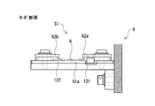
- FIG. 7 is a view showing a BB ′ cross section of FIG.
- FIG. 8 is a view showing a cross section taken along the line CC ′ of FIG.
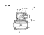
- FIG. 9 is a diagram showing a cross section along DD ′ of FIG.
- FIG. 10 is a diagram for explaining the wrapping web according to the first embodiment.
- FIG. 11 is a diagram illustrating a front folding guide portion and a rear folding guide portion of the folding guide according to the first embodiment.
- FIG. 1 is a schematic configuration diagram of a filter manufacturing machine 1 according to the first embodiment.
- the filter manufacturing machine 1 is an apparatus for manufacturing a cigarette filter (hereinafter simply referred to as “filter”) 100 attached to the cigarette C shown in FIG.
- the filter 100 is an example of a rod-shaped article for a smoking article according to the present invention.
- the filter 100 is connected to the tobacco rod 400 via the chip paper 300.
- the tobacco rod 400 is formed by winding a tobacco stamp 410 with a cigarette rod wrapping paper 420 to form a cylindrical shape (bar shape).
- the filter 100 includes, for example, a filter medium 110 such as cellulose acetate tow and a filter paper (hereinafter simply referred to as “wind paper”) 120 around which the filter medium 110 is wound.
- a solution is added to the filter medium 110 of the filter 100. Examples of the solution include an embodiment containing propylene glycol (PG), glycerin (G) and the like.
- FIG. 3 is a cross-sectional view of the filter 100 according to the first embodiment.
- a filter paper 120 is wound around the filter 100 along the circumferential direction of a filter medium 110 formed in a cylindrical shape.
- a liquid impervious layer 120a that suppresses the permeation of the solution L added to the filter medium 110 is formed.
- a resin material is preferable.
- Examples of the material for forming the liquid impermeable layer 62 include polyethylene, polypropylene, polystyrene, cellulose, acetyl cellulose, polytetrafluoroethylene, polyoxydimethylsilylene, polyvinyl acetate, polyvinyl chloride, polymethyl acrylate, and polymethacrylic acid. Mention may be made of one or more selected from methyl, natural rubber, polybutadiene, and copolymers thereof, aluminum, alumina and silica. Among these, polyethylene and polypropylene are particularly preferable as a material for forming the liquid impermeable layer 62.
- the liquid impervious layer 120a of the web 120 may be laminated on the surface of the substrate by means of coating or vapor deposition. In this embodiment, the liquid impervious layer 120a is formed by coating the base material of the web 120 with polyethylene.
- the web 120 is wound with the filter medium 110 with the liquid impervious layer 120 a facing inward so that the liquid impervious layer 120 a faces the outer peripheral surface of the filter medium 110.
- the web 120 has a palm portion 123 in which inner surfaces of a pair of first end region 121 and second end region 122 extending along the axial direction of the filter 100 are opposed to each other and overlapped with each other.
- the palm portion 123 is folded back to the adjacent winding portion 124 side where the filter medium 110 is wound adjacent to the adjacent winding portion 124, and is fixed by the adhesive paste 130 with the palm portion 123 attached to the adjacent winding portion 124.
- the first end region 121 is formed with a one-edge end 125 which is a folded back of the web 120, and the liquid impervious layer 120a at the one-edge end 125 is the second end portion 125.
- the liquid-impermeable layer 120a in the end region 122 is heat-sealed. More specifically, a bonding region in which the inner surface of the liquid impermeable layer 120a in the first end region 121 (one ear end portion 125) and the inner surface of the liquid impermeable layer 120a in the second end region 122 are overlapped with each other. At least a part is in a fused state without using a bonding agent.
- the positions of the end surface 121a of the first end region 121 (one ear end portion 125) and the end surface 122a of the second end region 122 are shifted, whereby a part (end surface 122a) of the second end region 122 is shifted.
- a non-wrapping inner surface region 122b that does not overlap with the inner surface of the first end region 63 is formed in the side region).
- An adhesive 130 is applied to the non-wrap inner surface region 122b in the second end region 122, and the non-wrap inner surface region 122b is adhered to the outer surface of the adjacent winding portion 124 by the adhesive 130, whereby the palm portion 123 is formed. It is fixed in a state of being attached to the adjacent winding part 124.
- the liquid impervious layer 120a in this embodiment is formed of polyethylene having a relatively low melting point, there is an advantage that it is easy to handle when heat-sealing.
- the liquid impervious layer 120a in the first end region 121 (one ear end 125) and the liquid impervious layer 120a in the second end region 122 are bonded together using a bonding agent resistant to liquid. Also good.
- the palm portion 123 is formed in a state where the liquid impervious layers 120a on the inner surface side in the first end region 121 and the second end region 122 are heat-sealed.
- the base material of the web 120 is suppressed from coming into contact with the solution L added to the filter medium 110. Thereby, it can suppress that the solution L added to the filter medium 110 penetrates into the base material of the web 120. Therefore, peeling of the first end region 121 and the second end region 122 on the web 120 can be suppressed.
- the exudation to the exterior of the solution L added to the filter medium 110 of the filter 100 can be suppressed. As a result, the appearance of the cigarette can be kept good.
- the filter manufacturing machine 1 includes a winding section 2 and a transport section 4.
- a continuous body of filter tow F that becomes the filter medium 110 of the filter 100 is supplied from a tow supply device (not shown).
- a known tow supply device can be applied as appropriate, and a continuous body of filter tow F to which the solution L is added is supplied to the winding section 2.
- the transport section 4 continuously transports and supplies the long web 8 serving as the web 120 of the filter 100 to the winding section 2.
- a filter rod FR that is a continuous body of the filter 100 is manufactured by wrapping the periphery of the continuous body of the filter tow F with a long web paper web 8.
- the transport section 4 is located below the winding section 2.
- the transport section 4 includes a bobbin 40 obtained by winding a long web paper web 8 in a roll shape.
- the bobbin 40 is set on a reel (not shown).
- the long web 8 wound around the bobbin 40 travels along a predetermined web travel path P and is continuously supplied to the winding section 2.
- the base material is coated with polyethylene that forms the liquid impermeable layer 120a described in FIG.
- the web travel path P in the transport section 4 is formed by a plurality of guide rollers 41.
- a pooling roller 42, a reservoir box 43, a suction brake 44, a paper guide 45, a folding guide 5, a rail paste application nozzle 47, a paper heater 48, and the like are arranged.
- the reservoir box 43 can store a long web paper web 8 therein before the bobbin 40 is replaced. Further, the pooling roller 42 feeds the long web paper web 8 toward the winding section 2 at a feeding speed that matches the traveling speed of the garniture tape 21 in the winding section 2 described later. In the present embodiment, the pooling roller 42 that feeds the long wrapping web 8 toward the winding section 2 corresponds to the feeding means.
- the suction brake 44 applies a braking force to the long wrapping web 8 traveling on the web travel path P, and causes the long wrapping web 8 supplied to the winding section 2 to have an appropriate tension, thereby loosening the slack. Is suppressed.
- the paper guide 45 is a guide member that adjusts the travel position of the web paper web 8 in the width direction of the long web paper web 8 traveling along the web travel path P.
- the width direction of the wrapping web 8 is a direction orthogonal to the longitudinal direction of the wrapping web 8.
- the rail paste application nozzle 47 continuously applies the rail paste to the coating surface of the long web paper web 8.
- the rail paste is an adhesive for adhering the coating surface of the wrapping web 8 to the filter tow F when the periphery of the continuous body of the filter tow F is wrapped by the long wrapping web 8 in the winding section 2.
- the rail paste application nozzle 47 continuously applies the rail paste along the longitudinal direction of the paper web 8 at a position near the center in the width direction of the paper web 8, for example.
- the paper heater 48 is a heater for appropriately heating the wrapping web 8 coated with rail paste.
- the filter tow F and the web paper web 8 are wrapped around the filter tow F by the paper web 8 in the winding section 2.
- the paper web web 8 is preliminarily warmed by the paper heater 48, so that the web paper web 8 and the paper adhesive 8 are fixed. Adhesiveness can be improved.
- the filter 100 manufactured by the filter manufacturing machine 1 has one ear end 125 formed in the first end region 121 of the web 120 around which the filter medium 110 is wound, and the liquid at the one ear end 125 is liquid.
- the impervious layer 120a is thermally fused to the liquid impervious layer 120a in the second end region 122, whereby the palm portion 123 of the web 120 is formed.
- the transport section 4 in the filter manufacturing machine 1 has one end side in the width direction of the wrapping web 8 along the longitudinal direction when the long wrapping web 8 passes through the folding guide 5 arranged on the web travel path P. It folds continuously and the one ear end part 125 is formed.
- FIG. 4 is a schematic configuration diagram of the folding guide 5 according to the first embodiment.
- FIG. 5 is a perspective view of the folding guide 5 according to the first embodiment.
- FIG. 6 is a view showing a cross section taken along the line AA ′ of FIG.
- FIG. 7 is a view showing a BB ′ cross section of FIG.
- FIG. 8 is a view showing a cross section taken along the line CC ′ of FIG.
- FIG. 9 is a diagram showing a cross section along DD ′ of FIG.
- the folding guide 5 includes a folding section 6, a ruled line roller unit 7, a press roller unit 9, and the like.
- the folded section 6 is a section in which one end region in the width direction of the long web paper web 8 is continuously folded along the longitudinal direction. Further, a ruled line roller unit 7 is disposed in the front stage of the folding section 6, and a press roller unit 9 is disposed in the rear stage of the folding section 6.
- the ruled line roller unit 7 has a pair of ruled line applying rollers 71 and 72. As shown in FIG. 6, in the ruled line roller unit 7, the long web paper web 8 is pressed by being sandwiched between a pair of ruled line applying rollers 71 and 72. As shown in the enlarged view surrounded by a broken line in FIG. 6, a protrusion 73 whose roller diameter is slightly larger than the other region is formed in one end region of the ruled line applying roller 72 located on the lower side. , Formed along the circumferential direction of the roller surface 72a.
- the protrusion 73 has an annular rib structure, and is formed to extend over the entire circumference of the roller surface 72a.
- the folding ruled line 82 is formed in the first end region 121 that is one end region of the wrapping web 8 as shown in FIG.
- symbol 81 in a figure is a coating surface by which polyethylene is coated among the wrapping paper webs 8.
- FIG. 1 since the ruled line roller unit 7 is continuously passed through the long web paper web 8, the folding ruled lines 82 can be continuously formed along the longitudinal direction of the web paper web 8.
- the folded section 6 includes a front section S1 positioned on the front stage side and a rear section S2 positioned on the rear stage side.
- the front section S 1 includes a traveling floor 61 a on which the long web paper web 8 travels, a front folding guide portion 62 a that guides the first end region 121 (see FIG. 10) side in the width direction of the web paper web 8, and the web paper web 8.
- a front guide portion 62b that guides the second end region 122 (see FIG. 10) side, which is the other end region in the width direction.
- the rear section S2 includes a traveling floor 61b on which the long web paper web 8 travels, a rear folding guide portion 63a that guides the first end region 121 side of the web paper web 8, and a second end region 122 of the web paper 8. It has a rear guide part 63b for guiding the side.
- Each traveling floor 61a, 61b of the front section S1 and the rear section S2 extends along the web traveling path P and is formed as a flat surface for traveling while supporting the wrapping web 8.
- the web paper web 8 is used.
- the surface opposite to the coating surface 81 is defined to travel in a state of facing the traveling floors 61a and 61b.
- symbols P1 and P2 in FIG. 4 represent the inlet end and the outlet end in the preceding section S1, respectively.
- Reference numerals P3 and P4 represent an inlet end and an outlet end in the rear section S2, respectively.
- an appropriate clearance for inserting and running the second end region 122 of the web paper web 8 is formed between the front guide portion 62b in the front section S1 and the traveling floor 61a on which the web paper web 8 travels. In this way, the second floor region 122 of the wrapping web 8 that has a ceiling surface (not shown) facing the traveling floor 61a and passes through the front section S1 is guided so as not to become unstable.
- an appropriate gap is formed between the rear guide portion 63b in the rear section S2 and the traveling floor 61b on which the web paper web 8 travels so that the second end region 122 of the web paper web 8 is inserted and travels.
- the second floor region 122 of the wrapping web 8 that has a ceiling surface (not shown) facing the traveling floor 61b and passes through the rear section S2 is guided so as not to become unstable.
- FIG. 11 shows the front-stage folding guide portion 62a and the rear-stage folding guide portion 63a that are removed from the folding guide 5.
- FIG. The front folding guide part 62a and the rear folding guide part 63a in FIG. 11 are shown in a state in which the top and bottom (upper and lower) are switched with reference to the state where they are installed at the normal positions of the folding section 6 as shown in FIG. ing.
- a first end region 121 (see FIGS. 7, 10, etc.) of the wrapping web 8 is guided to the front folding guide portion 62a and the rear folding guide portion 63a, and the folding ruled line 82 is guided.
- a first guide wall 621 and a second guide wall 631 are provided for turning back at the boundary.
- symbol 622 shown in FIG. 11 represents the ceiling surface of the front
- the ceiling surface 622 of the front folding guide portion 62a is between the traveling floor 61a on which the web paper web 8 travels in a state where the front folding guide portion 62a is mounted on the folding guide 5 and the first end region of the web paper web 8 is.
- symbol 632 shown in FIG. 11 represents the ceiling surface of the back
- the ceiling surface 632 of the rear-stage folding guide portion 63a is between the traveling floor 61b on which the web paper web 8 travels in a state where the rear-stage folding guide portion 63a is mounted on the folding guide 5 and the first end region of the web paper web 8 is. It arrange
- the shape of the first guide wall 621 in the front folding guide part 62a gradually changes from the start end portion 621a to the end end portion 621b.
- the shape of the second guide wall 631 in the rear turn-back guide portion 63a gradually changes from the start end portion 631a to the end end portion 631b.
- the first end region 121 of the wrapping web 8 is gradually folded.
- the first guide wall 621 in the front folding guide portion 62a bends the first end region 121 of the wrapping web 8 to 90 ° with the folding ruled line 82 as a boundary.
- the second guide wall 631 in the rear-stage folded guide portion 63a is configured to finally fold the wrapping web 8 in a state where the first end region 121 is folded to 90 ° by the first guide wall 621 to 180 °. It has become.
- the first guide wall 621 in the front bending guide portion 62a has an angle formed with the ceiling surface 622 at the start end portion 621a (hereinafter referred to as “guide wall angle”) is 180 °.
- the first guide wall 621 is formed as a guide surface that continues in parallel from the ceiling surface 622. Then, as shown in FIG. 11, the first guide wall 621 gradually rises from the start end 621a of the first guide wall 621 toward the end end 621b, and between the start end 621a and the end end 621b. In the middle portion 621 c located in the middle, the first guide wall 621 stands up to a posture perpendicular to the ceiling surface 622.
- the guide wall angle of the first guide wall 621 gradually decreases from the start end 621a toward the end end 621b, and the guide wall angle becomes 90 ° at the intermediate portion 621c.
- the guide wall angle is maintained at 90 ° from the intermediate portion 621c to the end portion 621b of the first guide wall 621. That is, the first guide wall 621 is maintained in an upright posture with respect to the ceiling surface 622 from the intermediate portion 621c to the terminal end portion 621b of the first guide wall 621.
- the second guide wall 631 in the rear turn-back guide portion 63a has an angle (hereinafter referred to as “guide wall angle”) of 90 ° with the ceiling surface 632 at the start end portion 631a.
- the guide wall angle is maintained at 90 ° up to an intermediate portion 631c located in the middle between the start end portion 631a and the end portion 631b.
- the guide wall angle is maintained at 90 ° in the section from the start end portion 631a to the intermediate portion 631c of the second guide wall 631, so that the posture stands upright with respect to the ceiling surface 632 Is maintained.
- the second guide wall 631 is continuously warped from the intermediate portion 613c to the terminal end portion 631b of the second guide wall 631, and as a result, the guide wall angle gradually decreases from 90 °.
- the guide wall angle is substantially 0 ° at the end portion 631b of the second guide wall 631.
- the start end 621a and the end 621b of the first guide wall 621 are respectively connected to the inlet end P1 and the outlet of the front section S1. It is arranged at the position of the end P2.
- the start end portion 631a and the end end portion 631b of the second guide wall 631 are disposed at the positions of the inlet end P3 and the outlet end P4 in the rear stage section S2, respectively. It is like that.
- the position of the folding ruled line 82 in the wrapping web 8 matches the boundary 624 between the ceiling surface 622 and the first guide wall 621 at the start end 621a of the first guide wall 621.
- the wrapping web 8 is transferred to the inlet end P1 of the preceding section S1 in the folded section 6.
- the wrapping web 8 transferred to the inlet end P1 of the front section S1 is gradually bent with the folding ruled line 82 as a boundary when the first end region 121 contacts the first guide wall 621.
- the bending angle of the first end region 121 in the wrapping web 8 is changed from 0 ° by changing the guide wall angle from 180 ° to 90 ° over the section from the inlet end P1 to the outlet end P2 of the front section S1. Changed to 90 °.
- the wrapping web 8 in which the first end region 121 is folded up to 90 ° with the folding ruled line 82 as a boundary in the front section S1 is transferred to the rear section S2.
- FIG. 11 schematically shows the transition of the bending angle of the wrapping web 8.
- the wrapping web 8 transferred to the rear section S2 is further folded with the folding ruled line 82 as a boundary when the first end region 121 comes into contact with the second guide wall 631.
- the guide wall angle is changed from 90 ° to 0 ° over the section from the inlet end P3 to the outlet end P4 of the rear section S2, so that the bending angle of the first end region 121 in the wrapping web 8 is 90 °.
- the angle is changed to 180 °, and one end portion 125 is formed in which the first end region 121 is folded back at the folding ruled line 82.
- FIG. 8 shows a state in which the first end region 121 of the wrapping web 8 is folded by 135 ° with the folding ruled line 82 as a boundary.
- the first end region 121 is continuously formed along the longitudinal direction of the wrapping web 8 when the long wrapping web 8 passes.
- the one ear end portion 125 can be suitably formed by folding back.
- the press roller unit 9 includes a pair of press rollers 91 and 92, and the wrapping web 8 is sandwiched therebetween and pressed.
- the wrapping web 8 has a pair of presses in a state where the one ear end 125 is overlapped with an inner region 83 (see FIG. 9) formed inside the one ear end 125. Pressed by rollers 91 and 92.
- folded with the ruled line 82 for folding can be attached exactly.
- the folding ruled line 82 is previously formed in the first end region 121 of the wrapping web 8 in the crease roller unit 7 before the wrapping web 8 is transferred to the folding section 6. Therefore, the first end region 121 can be folded back at a desired position in the folded section 6 with high accuracy. Thereby, the dimensional accuracy of the one ear
- the folding guide 5 is arranged on the downstream side (downstream side) of the paper guide 45 in the web travel path P in the transport section 4. According to this, the wrapping web 8 after the position in the width direction of the paper guide 45 is adjusted to an appropriate position can be transferred to the folding guide 5, and the dimensional error of the one-ear end portion 125 is less likely to occur.
- the folding guide 5 is disposed in front of the rail glue application nozzle 47 in the web travel path P in the transport section 4, the rail glue is passed when the wrapping web 8 passes through the folding guide 5. Adhering to the traveling floors 61a, 61b, etc. of the folding guide 5 can be suppressed.
- the guide roller 41 (a) in which (a) is written is the wrapping web 8 while sliding the one end portion 125 formed on the folded guide 5.
- a roller that guides the wrapping web 8 while curving one ear end portion 125 inward and hereinafter referred to as an “inner curved guide roller”.
- the guide roller 41 (b) in which (b) is written together among the plurality of guide rollers 41 shown in FIG. 1 is one ear formed on the folding guide 5, contrary to the “inner curved guide roller” described above.
- the wrapping web 8 passes through the inner curved guide roller 41 (b), it passes through the inner curved guide roller 41 (b) with respect to the inner region 83 of the wrapping web 8.
- the posture of the folded one ear end portion 125 easily returns to the original posture.
- the paper heater 48 is arranged in the web travel path P in the transport section 4 immediately after the inner curved guide roller 41 (a) (directly downstream).
- the paper heater 48 is a heater combined guide that slidably contacts the surface (the coating surface 81 in this embodiment) of the wrapping web 8 traveling along the web traveling path P in order to warm the rail paste applied to the wrapping web 8. It has a surface 48a.
- the web paper web 8 passes through the paper heater 48, the long web paper web 8 is warmed by the heater / guide surface 48a of the paper heater 48, and the web paper web 8 is given an appropriate tension, so that It is possible to easily maintain the posture in which the end portion 125 is folded with respect to the inner region portion 83.
- the winding section 2 includes a forming bed 20 extending in the horizontal direction.
- a molding groove (not shown) is formed on the upper surface of the molding bed 20, and the molding groove extends from the start end 20 a to the end 20 b of the molding bed 20.
- the forming groove is flat at the start end 20a, the depth of the forming groove gradually increases toward the end 20b, while the width of the forming groove gradually decreases toward the end 20b.
- the forming groove has a semicircular cross section at the end 20b.
- the winding section 2 further includes an endless garniture tape 21.
- a part of the garniture tape 21 is disposed in the molding groove of the molding bed 20.
- the garniture tape 21 is wound around a driving drum 22 rotated by a motor (not shown) below the molding bed 20 at a predetermined wrapping angle, and its traveling is guided by a plurality of guide rollers 23. Yes.
- the drive drum 22 When the drive drum 22 is rotated, the garniture tape 21 travels on the forming groove of the forming bed 20 from the start end 20a toward the end end 20b.
- the long wrapping web 8 fed out from the bobbin 40 travels along the web travel path P and is continuously supplied onto the garniture tape 21 in the winding section 2.
- a continuous body of filter tow F is supplied to the entrance of the winding section 2 from a tow supply device (not shown) at a speed that matches the traveling speed of the garniture tape 21. Is stacked on the long web paper web 8.
- a solution L containing propylene glycol or glycerin is added in advance by a tow supply device.
- the winding section 2 further includes a stuffer jet 24, a trumpet guide 25, a tong 26, a molding holder 27 having a glue gun 27a, a heater 28, a cooler 29, and the like.
- the stuffer jet 24 receives supply of compressed air, so that a continuous body of the filter tow F continuously supplied from the tow supply device is transferred to the trumpet guide 25 arranged at the rear stage. Force stuffing.
- the trumpet guide 25 has, for example, a substantially funnel shape, and guides the continuous body of filter tows F sent from the stuffer jet 24 toward the tongue 26 while collecting them in a rod shape (bar shape).
- the continuous filter tow F formed into a rod shape in the trumpet guide 25 is overlapped on the wrapping web 8 on the garniture tape 21 on the start end 20a side of the forming bed 20, and adhered to the wrapping web 8 with rail glue. Thereafter, the wrapping web 8 and the filter toe F travel along the molding groove on the molding bed 20 together with the garniture tape 21.
- the tong 26, the forming holder 27, the heater 28, and the cooler 29 are sequentially disposed immediately above the forming bed 20 from the start end 20a side.
- the tongue 26 squeezes the filter toe F from above and further compresses the filter toe F in cooperation with the forming groove of the forming bed 20.
- the garniture tape 21 and the wrapping web 8 are bent into a U shape so as to wrap the filter tow F from below along the forming groove.
- the coating surface 81 of the web 8 is opposed to the outer peripheral surface of the filter tow F.
- both side edges of the wrapping web 8 are sequentially bent toward the filter toe F through the garniture tape 21.
- the molding holder 27 is provided with the spray gun 27a that discharges the adhesive paste.
- the glue gun 27 a applies fixing glue to the coating surface 81 of the second end region 122 of the wrapping web 8.
- the glue gun 27a can continuously apply the adhesive paste along the longitudinal direction of the wrapping web 8 by discharging the adhesive paste continuously.
- the wrapping web 8 on which the adhesive paste from the glue gun 27a is applied to the coating surface 81 of the second end region 122 is composed of the first end region 121 in which the one end portion 125 is formed by the folding guide 5 and the opposite side.
- the second end region 122 is overlaid and the outer peripheral surface of the filter tow F is wrapped by the wrapping web 8.
- the coating surface 81 of the second end region 122 is covered with the coating surface 81 of the one end portion 125 of the wrapping web 8 and the coating surface 81 (
- the adhesive paste 130 applied to the liquid impervious layer 120a) is adhered to the inner region 83 in the first end region 121 (see FIG. 3).
- hot melt can be suitably used as the fixing paste 130.
- the hot melt paste for example, ethylene vinyl acetate copolymer (EVA) type hot melt can be suitably used.
- the continuous body of the filter rod FR is transferred to the heater 28 and heated.
- the coating surface 81 at the one end portion 125 of the wrapping web 8 and the coating surface 81 of the second end region 122 are heated to face each other. Is done.
- the polyethylene coated on the coating surfaces 81 of the first end region 121 and the second end region 122 of the wrapping web 8 is heat-sealed, and these can be bonded together.
- polyethylene since polyethylene has a relatively low melting point, there is an advantage that it is easy to handle when heat-sealing.
- the adhesive paste 130 (for example, hot melt) applied from the glue gun 27 a to the wrapping web 8 is reheated by the heating by the heater 28, and the first end region 121 and the second end region 122 of the wrapping web 8 are reheated. Bonding becomes stronger.
- the continuous body of the filter rod FR that has passed through the heater 28 is transferred to the cooler 29 and cooled.
- the cutting device 11 is disposed at the rear stage of the cooler 29.
- the continuous body of filter rods FR transferred to the cutting device 11 is cut at predetermined lengths in the cutting device 11.
- individual filters 100 are formed.
- the filter 100 formed in this way is received by the receiver 12 from the cutting device 11 and then transferred to a filter cigarette manufacturing machine, a so-called filter mounting machine.
- the cigarette rod 400 and the filter 100 are integrally wound by the chip paper 300 to form a filter cigarette.
- the filter manufacturing machine 1 of the present embodiment when the folding guide 5 disposed in the conveyance path of the long web paper web 8 is passed through the web paper web 8 in the conveyance section 4, the paper folding web 8 is folded.
- One end portion 125 is formed in the first end region 121 by continuously folding back the first end region 121 of the wrapping web 8 along the longitudinal direction by the guide 5, and the wrapping section 2
- the filter toe F that is the winding target portion by the wrapping web 8 while the coating surfaces 81 of the one end portion 125 formed in the first end region 121 and the coating surface 81 of the second end region 122 face each other. It was made to wind continuously.
- the filter 100 shown by FIG. 3 can be manufactured suitably.
- the one ear end portion 125 of the first end region 121 and the coating surface 81 of the second end region 122 of the wrapping web 8 are overlapped and heat-sealed.
- the palm portion 123 can be formed as an end joint structure of the web 120 in the filter 100 shown in FIG.
- the adhesive paste 130 applied to the coating surface 81 of the second end region 122 of the wrapping web 8 is adhered to the inner region 83 of the first end region 121.
- the palm portion 123 of the web 120 can be fixed in a state of being attached to the adjacent winding portion 124. Therefore, the shape of the filter 100 is suppressed from becoming distorted, and a good circular shape can be maintained.
- the one-edge end portion 125 is formed in advance on the web paper web 8 by the folding guide 5 arranged in the transport section 4. Therefore, it is possible to suppress the adhesive paste 130 from adhering to the traveling floors 61a, 61b of the folding guide 5 and the like.
- the palm portion 123 of the web 120 is heat-sealed between the liquid impervious layers 120a of the first end region 121 and the second end region 123.
- the first end region 121 and the second end region 121 are the same.
- the heat fusion between the liquid impermeable layers 120a in the first end region 121 and the second end region 122 may be omitted.
- a long web paper web 8 supplied to the winding section 2 by the transport section 4 is used with one surface coated with polyethylene. You may use the thing in which the coating which forms a permeable layer is not formed. Moreover, you may use the manufacturing apparatus and its manufacturing method of the rod-shaped article for smoking articles in this embodiment, for example in order to form the one ear
Landscapes
- Cigarettes, Filters, And Manufacturing Of Filters (AREA)
Abstract
巻装対象部を巻装する巻紙の端部領域同士の接合部分を従来に比べて剥離しにくくすることができる喫煙物品用棒状物品の製造機およびその製造方法を提供する。喫煙物品用棒状物品の製造機であって、長尺の巻紙の幅方向における一端領域に形成された片耳端部と他端領域の内面同士を互いに対向させて重ね合せつつ長尺の巻紙によって巻装対象部の周囲を連続的に巻上げる巻装セクションと、巻装セクションの前段に配置され、巻装セクションに長尺の巻紙を搬送する搬送セクションとを備え、搬送セクションは、長尺の巻紙を巻装セクションに向かって送り出す送出手段と、送出手段によって送り出される長尺の巻紙の搬送経路上に配置されて長尺の巻紙が通過する際に一端領域を長手方向に沿って連続的に折り返すことで一端領域に片耳端部を形成する折り返しガイドと、を有する。
Description
本発明は、喫煙物品用棒状物品の製造機およびその製造方法に関する。
シガレットなどの棒状喫煙物品における巻紙として、棒状喫煙物品用フィルターの濾材を巻装する巻取り紙およびフィルターとたばこロッドを一体に巻装するチップペーパーなどのフィルター用巻紙や、たばこロッドのたばこ刻を巻装するロッド用巻紙などが知られている。これら棒状喫煙物品に用いられる巻紙は、棒状喫煙物品の製造過程において、巻装対象部の周方向に沿って巻装した後、その端部領域同士を互いに重ね合わせて接着するなどして接合し、円筒状に成形されている。従来における巻紙の端部接合構造は、棒状喫煙物品の巻装対象部を巻装する巻紙における一方の端部領域の外面に他方の端部流域の内面を重ね合わせ、その重ね合せた端部領域同士を接着剤によって接着していた。
しかしながら、例えば蔵置中などに外力が掛ってたばこロッドやフィルターなどの喫煙物品用棒状物品が変形した際に、従来における巻紙の端部接合構造では、巻紙における端部領域同士の接着部分が剥離してしまう虞があった。
本発明は、このような実情に鑑みてなされたものであって、巻装対象部を巻装する巻紙の端部領域同士の接合部分を従来に比べて剥離しにくくすることができる喫煙物品用棒状物品の製造機およびその製造方法を提供することを目的とする。
本発明では、上記課題を解決するために、長尺の巻紙の搬送経路中に配置された折り返しガイドを該長尺の巻紙に通過させる際に、折り返しガイドによって長尺の巻紙における一端領域を長手方向に沿って連続的に折り返すことで該一端領域に片耳端部を形成するようにした。
より詳しくは、本発明は、喫煙物品用棒状物品の製造機であって、長尺の巻紙の幅方向における一端領域に形成された片耳端部と他端領域の内面同士を互いに対向させて重ね合せつつ該長尺の巻紙によって巻装対象部の周囲を連続的に巻装する巻装セクションと、前記巻装セクションの前段に配置され、該巻装セクションに長尺の巻紙を搬送する搬送セクションと、を備え、前記搬送セクションは、前記長尺の巻紙を前記巻装セクションに向かって送り出す送出手段と、前記送出手段によって送り出される前記長尺の巻紙の搬送経路上に配置されて、前記長尺の巻紙が通過する際に前記一端領域を長手方向に沿って連続的に折り返すことで該一端領域に片耳端部を形成する折り返しガイドと、を有することを特徴とする。
また、本発明において、前記折り返しガイドは、前記長尺の巻紙における前記一端領域を長手方向に沿って連続的に折り返す折り返しセクションを含み、前記折り返しセクションには、該折り返しセクションを通過する前記長尺の巻紙の一端領域に接触して該一端領域を徐々に折り込むガイド壁が配設されていてもよい。
また、本発明において、前記折り返しガイドは、前記折り返しセクションの前段に配設される罫線ローラーユニットを有し、前記長尺の巻紙に前記罫線ローラーユニットを通過させることで、前記長尺の巻紙における前記一端領域に折り込み用罫線を形成してもよい。
また、本発明において、前記折り返しガイドは、前記折り返しセクションの後段に配設されるプレスローラーユニットを有し、前記長尺の巻紙に前記プレスローラーユニットを通過させることで、前記長尺の巻紙における前記一端領域に形成された前記片耳端部をその内側に形成された内側領域部に重ね合せた状態でプレスするように構成されていてもよい。
また、本発明は喫煙物品用棒状物品の製造方法として捉えることができる。即ち、本発明は、喫煙物品用棒状物品の製造方法であって、長尺の巻紙の搬送経路中に配置された折り返しガイドを該長尺の巻紙に通過させる際に、前記折り返しガイドによって前記長尺の巻紙における一端領域を長手方向に沿って連続的に折り返すことで該一端領域に片耳端部を形成し、前記長尺の巻紙における前記一端領域に形成された前記片耳端部と他端領域の内面同士を互いに対向させて重ね合せつつ該長尺の巻紙によって巻装対象部の周囲を連続的に巻装することを特徴とする。
また、本発明において、前記折り返しガイドは、前記長尺の巻紙における前記一端領域を長手方向に沿って連続的に折り返す折り返しセクションを含み、前記長尺の巻紙が前記折り返しセクションを通過する際、該折り返しセクションに配設されるガイド壁に前記長尺の巻紙の一端領域を接触させることで該一端領域を徐々に折り込むようにしてもよい。
また、本発明において、前記折り返しガイドは、前記折り返しセクションの前段に配設される罫線ローラーユニットを前記長尺の巻紙に通過させることで、前記長尺の巻紙における前記一端領域に折り込み用罫線を形成するようにしてもよい。
また、本発明において、前記折り返しガイドは、前記折り返しセクションの後段に配設されるプレスローラーユニットを前記長尺の巻紙に通過させることで、前記長尺の巻紙における前記一端領域に形成された前記片耳端部をその内側に形成された内側領域部に重ね合せた状態でプレスするようにしてもよい。
なお、本発明における課題を解決するための手段は、可能な限り組み合わせて採用することができる。
本発明によれば、巻装対象部を巻装する巻紙の端部領域同士の接合部分を従来に比べて剥離しにくくすることができる喫煙物品用棒状物品の製造機およびその製造方法を提供することができる。
ここで、本発明に係る喫煙物品用棒状物品の製造機およびその製造方法の実施形態について、図面に基づいて説明する。また、本実施形態に記載されている構成要素の寸法、材質、形状、その相対配置等は、特に特定的な記載がない限りは、発明の技術的範囲をそれらのみに限定する趣旨のものではない。
<実施形態1>
図1は、実施形態1に係るフィルター製造機1の概略構成図である。フィルター製造機1は、図2に示すシガレットCに取り付けられるシガレット用フィルター(以下、単に「フィルター」と呼ぶ)100を製造する装置である。フィルター100は、本発明に係る喫煙物品用棒状物品の一例である。
図1は、実施形態1に係るフィルター製造機1の概略構成図である。フィルター製造機1は、図2に示すシガレットCに取り付けられるシガレット用フィルター(以下、単に「フィルター」と呼ぶ)100を製造する装置である。フィルター100は、本発明に係る喫煙物品用棒状物品の一例である。
まず、フィルター製造機1によって製造されるフィルター100の概略構造について説明する。フィルター100は、チップペーパー300を介してたばこロッド400と接続されている。たばこロッド400は、たばこ刻410をたばこロッド用巻紙420で巻装して円柱状(棒形状)に成形したものである。フィルター100は、例えばセルロースアセテートトウなどの濾材110と、濾材110を巻装するフィルター用巻取紙(以下、単に「巻取紙」と呼ぶ)120を含んでいる。フィルター100の濾材110には、溶液が添加されている。溶液は、例えばプロピレングリコール(PG)、グリセリン(G)などを含有する態様が挙げられる。
図3は、実施形態1に係るフィルター100の横断面図である。フィルター100は、円柱状に成形された濾材110の周方向に沿って巻取紙120が巻装されている。巻取紙120の内面側には、濾材110に添加されている溶液Lが透過することを抑制する液体不透過層120aが形成されている。液体不透過層120aを形成する材料としては、樹脂材料が好ましい。液体不透過層62を形成する材料として、例えば、ポリエチレン、ポリプロピレン、ポリスチレン、セルロース、アセチルセルロース、ポリテトラフルオロエチレン、ポリオキシジメチルシリレン、ポリ酢酸ビニル、ポリ塩化ビニル、ポリアクリル酸メチル、ポリメタクリル酸メチル、天然ゴム、ポリブタジエン、及びこれらの共重合体、アルミニウム、アルミナ及びシリカから選ばれる1以上を挙げることができる。これらの中では、ポリエチレン、ポリプロピレンが、液体不透過層62を形成する材料として特に好ましい。また、巻取紙120の液体不透過層120aは、基材の表面にコーティング、或いは蒸着等の手段で積層させてもよい。本実施形態においては、巻取紙120の基材にポリエチレンをコーティングすることで、液体不透過層120aを形成している。
図3に示すように、巻取紙120は、濾材110の外周面に液体不透過層120aが対向するように、液体不透過層120aを内側に向けて濾材110を巻装している。巻取紙120は、フィルター100の軸方向に沿って延びる一対の第1端部領域121と第2端部領域122における内面同士を互いに対向させて重ね合せた合掌部123を有し、合掌部123に隣接すると共に濾材110を巻装する隣接巻装部124側に合掌部123を折り返し、隣接巻装部124に合掌部123を添わせた状態で固着糊130によって固着している。
巻取紙120の合掌部123を更に詳しく説明すると、第1端部領域121には、巻取紙120を折り返した片耳端部125が形成されており、片耳端部125における液体不透過層120aが、第2端部領域122における液体不透過層120aと熱融着されている。より具体的には、第1端部領域121(片耳端部125)における液体不透過層120aの内面と、第2端部領域122における液体不透過層120aの内面を互いに重ね合わせた接合領域の少なくとも一部が、接合剤を介さずに融着された状態となっている。また、第1端部領域121(片耳端部125)における液体不透過層120aの内面と第2端部領域122における液体不透過層120aの内面を互いに重ね合わせた接合領域の全体(全領域)を、接合剤を介さずに融着してもよい。また、第1端部領域121(片耳端部125)の端面121aおよび第2端部領域122の端面122aの位置がずらされており、これによって、第2端部領域122の一部(端面122a側の領域)に第1端部領域63の内面と重なり合わない非ラップ内面領域122bが形成されている。第2端部領域122における非ラップ内面領域122bには接着剤130が塗布され、この接着剤130によって非ラップ内面領域122bが隣接巻装部124の外面に接着されることで、合掌部123が隣接巻装部124に添わせられた状態で固着される。なお、本実施形態における液体不透過層120aは、比較的融点が低いポリエチレンによって形成されているため、熱融着させる際に取扱い易いという利点がある。また、本実施形態においては、第1端部領域121(片耳端部125)における液体不透過層120aの内面と第2端部領域122における液体不透過層120aの内面を互いに重ね合わせた接合領域を接着剤を介さずに熱融着させるため、接着剤を用いていない分だけ接合領域の厚さを薄くすることができるという利点もある。但し、第1端部領域121(片耳端部125)における液体不透過層120aおよび第2端部領域122における液体不透過層120aを、液体に対して耐性のある接合剤を用いて貼り合わせてもよい。
上記構成に係るフィルター100によれば、第1端部領域121および第2端部領域122における内面側の液体不透過層120a同士が熱融着された状態で合掌部123が形成されているため、巻取紙120の基材が濾材110に添加された溶液Lに接触することが抑制される。これにより、濾材110に添加された溶液Lが巻取紙120の基材に染み込むことを抑制できる。よって、巻取紙120における第1端部領域121および第2端部領域122の剥離を抑制できる。また、フィルター100の濾材110に添加されている溶液Lの外部への染み出しを抑制できる。その結果、シガレットの外観を良好に保つことができる。
次に、上記のように構成されるフィルター100を製造するフィルター製造機1の詳細について説明する。図1に示されるように、フィルター製造機1は、巻装セクション2および搬送セクション4を備えている。巻装セクション2には、フィルター100の濾材110となるフィルタートウFの連続体が図示しないトウ供給装置から供給される。トウ供給装置は公知のものを適宜適用することができ、溶液Lを添加したフィルタートウFの連続体を巻装セクション2に供給する。一方、搬送セクション4は、フィルター100の巻取紙120となる長尺の巻紙ウエブ8を巻装セクション2に連続的に搬送および供給する。巻装セクション2においては、フィルタートウFの連続体における周囲を長尺の巻紙ウエブ8によって包み込むことで、フィルター100の連続体であるフィルターロッドFRが製造される。
図1に示す例では、搬送セクション4が巻装セクション2の下方に位置している。搬送セクション4は、長尺の巻紙ウエブ8をロール状に巻き取ったボビン40を備えている。ボビン40は、図示しないリールにセットされている。また、ボビン40に巻かれている長尺の巻紙ウエブ8は、所定のウエブ走行経路Pに沿って走行し、巻装セクション2に連続的に供給される。また、巻紙ウエブ8における一方の面(以下、「コーティング面」と呼ぶ)には、図3で説明した液体不透過層120aを形成するポリエチレンが基材にコーティングされている。
ここで、搬送セクション4におけるウエブ走行経路Pは、複数のガイドローラー41から形成されている。ウエブ走行経路Pの途中には、プーリングローラー42、リザーバボックス43、サクションブレーキ44、ペーパーガイド45、折り返しガイド5、レール糊塗布ノズル47、ペーパーヒーター48などが配置されている。
リザーバボックス43は、ボビン40の交換に先立ち、その内部に長尺の巻紙ウエブ8を蓄えることができる。また、プーリングローラー42は、後述する巻装セクション2におけるガニチャテープ21の走行速度に一致する繰り出し速度にて、長尺の巻紙ウエブ8を巻装セクション2に向けて繰り出す。本実施形態においては、長尺の巻紙ウエブ8を巻装セクション2に向かって送り出すプーリングローラー42が送出手段に相当する。サクションブレーキ44は、ウエブ走行経路Pを走行する長尺の巻紙ウエブ8に制動力を与え、巻装セクション2に供給される長尺の巻紙ウエブ8に適度な張りを持たせることで、その弛みを抑えている。ペーパーガイド45は、ウエブ走行経路Pを走行する長尺の巻紙ウエブ8の幅方向について、巻紙ウエブ8の走行位置を調整するガイド部材である。巻紙ウエブ8の幅方向とは、当該巻紙ウエブ8の長手方向に直交する方向である。
レール糊塗布ノズル47は、長尺の巻紙ウエブ8のコーティング面にレール糊を連続して塗布する。レール糊は、巻装セクション2において、フィルタートウFの連続体の周囲を長尺の巻紙ウエブ8によって包み込む際に、フィルタートウFに巻紙ウエブ8のコーティング面を接着するための接着剤である。レール糊塗布ノズル47は、例えば巻紙ウエブ8の幅方向における中央部付近の位置に、巻紙ウエブ8の長手方向に沿って連続してレール糊を塗布する。
ペーパーヒーター48は、レール糊が塗布された巻紙ウエブ8を適度に温めるためのヒーターである。ペーパーヒーター48によって、巻紙ウエブ8のコーティング面に塗布されたレール糊を若干乾燥させることで、巻装セクション2においてフィルタートウFの周囲を巻紙ウエブ8によって包み込む際に、フィルタートウFと巻紙ウエブ8との間の接着性を高めるようにしている。また、後述するように、長尺の巻紙ウエブ8には、巻装セクション2において固着糊が塗布されるところ、ペーパーヒーター48によって巻紙ウエブ8を予め温めておくことで、巻紙ウエブ8と固着糊との接着性を高めることができる。
次に、ウエブ走行経路Pにおけるペーパーガイド45とレール糊塗布ノズル47との間に配置される折り返しガイド5について説明する。フィルター製造機1において製造するフィルター100は、図3で説明したように、濾材110を巻装する巻取紙120における第1端部領域121に片耳端部125が形成され、この片耳端部125における液体不透過層120aが第2端部領域122における液体不透過層120aと熱融着されることで、巻取紙120の合掌部123が形成されている。フィルター製造機1における搬送セクション4は、ウエブ走行経路P上に配置される折り返しガイド5を長尺の巻紙ウエブ8が通過する際に、巻紙ウエブ8の幅方向における一端側を長手方向に沿って連続的に折り返し、片耳端部125を形成する。
図4は、実施形態1に係る折り返しガイド5の概略構成図である。図5は、実施形態1に係る折り返しガイド5の斜視図である。図6は、図4のA-A´断面を示す図である。図7は、図4のB-B´断面を示す図である。図8は、図4のC-C´断面を示す図である。図9は、図4のD-D´断面を示す図である。
折り返しガイド5は、折り返しセクション6、罫線ローラーユニット7、プレスローラーユニット9などを含む。折り返しセクション6は、長尺の巻紙ウエブ8の幅方向における一端領域を長手方向に沿って連続的に折り返すセクションである。また、折り返しセクション6の前段に罫線ローラーユニット7が配置され、折り返しセクション6の後段にプレスローラーユニット9が配置されている。
罫線ローラーユニット7は、一対の罫線付与ローラー71,72を有する。図6に示すように、罫線ローラーユニット7において、長尺の巻紙ウエブ8は一対の罫線付与ローラー71,72の間に挟まれることで押圧される。図6において破線で囲まれた拡大図に示すように、下方側に位置する罫線付与ローラー72における一方の端部領域には、他の領域に比べてローラー直径が一回り大きくなる突起部73が、ローラー面72aの周方向に沿って形成されている。突起部73は環状リブ構造を有しており、ローラー面72aの全周に亘って延伸形成されている。
罫線ローラーユニット7における一対の罫線付与ローラー71,72間を巻紙ウエブ8が通過する際、この罫線付与ローラー72のローラー面72aに形成されている突起部73が巻紙ウエブ8の表面に押し当てられる結果、図10に示すように巻紙ウエブ8の一端領域である第1端部領域121に、折り込み用罫線82が形成される。なお、図中の符号81は、巻紙ウエブ8のうち、ポリエチレンがコーティングされているコーティング面である。なお、本実施形態においては、長尺の巻紙ウエブ8に罫線ローラーユニット7を連続的に通過させるため、巻紙ウエブ8の長手方向に沿って折り込み用罫線82を連続的に形成することができる。
上記のように、罫線ローラーユニット7を通過する際に、第1端部領域121に折り込み用罫線82が形成された巻紙ウエブ8は、後段の折り返しセクション6へと移送される。図5に示すように、折り返しセクション6は、前段側に位置する前段セクションS1と、後段側に位置する後段セクションS2を含んでいる。前段セクションS1は、長尺の巻紙ウエブ8が走行する走行床61a、巻紙ウエブ8の幅方向における第1端部領域121(図10を参照)側をガイドする前段折り曲げガイド部62a、巻紙ウエブ8の幅方向における他端領域である第2端部領域122(図10を参照)側をガイドする前段ガイド部62bを有する。また、後段セクションS2は、長尺の巻紙ウエブ8が走行する走行床61b、巻紙ウエブ8の第1端部領域121側をガイドする後段折り返しガイド部63a、巻紙ウエブ8の第2端部領域122側をガイドする後段ガイド部63bを有する。
前段セクションS1および後段セクションS2の各走行床61a,61bは、ウエブ走行経路Pに沿って伸びており、巻紙ウエブ8を支持しつつ走行させるための平坦面として形成されている。本実施形態では、ウエブ走行経路Pに沿って搬送される長尺の巻紙ウエブ8が、折り返しセクション6(前段セクションS1,後段セクションS2)の走行床61a,61b上を走行する際、巻紙ウエブ8のコーティング面81とは反対側の面が走行床61a,61bに対向した状態で走行するように規定されている。
ここで、図4における符号P1およびP2は、前段セクションS1における入口端および出口端をそれぞれ表す。また、符号P3およびP4は、後段セクションS2における入口端および出口端をそれぞれ表す。なお、前段セクションS1における前段ガイド部62bは、巻紙ウエブ8が走行する走行床61aとの間に、巻紙ウエブ8の第2端部領域122を挿入して走行させるための適度な隙間が形成されるように走行床61aと対向する天井面(図示せず)を有し、前段セクションS1を通過する巻紙ウエブ8の第2端部領域122の姿勢が不安定にならないようにガイドしている。また、後段セクションS2における後段ガイド部63bは、巻紙ウエブ8が走行する走行床61bとの間に、巻紙ウエブ8の第2端部領域122を挿入して走行させるための適度な隙間が形成されるように走行床61bと対向する天井面(図示せず)を有し、後段セクションS2を通過する巻紙ウエブ8の第2端部領域122の姿勢が不安定にならないようにガイドしている。
次に、前段セクションS1における前段折り曲げガイド部62aおよび後段セクションS2の後段折り返しガイド部63aの詳細構造について説明する。ここで、図11に、折り返しガイド5から取り外した状態の前段折り曲げガイド部62aと後段折り返しガイド部63aを示す。図11における前段折り曲げガイド部62aと後段折り返しガイド部63aは、図5に示すようにこれらを折り返しセクション6の正規位置に設置した状態を基準として、天地(上下)が入れ替えられた状態が示されている。
図11に示すように、前段折り曲げガイド部62aおよび後段折り返しガイド部63aには、巻紙ウエブ8の第1端部領域121(図7、図10等を参照)をガイドして、折り込み用罫線82を境に折り返すための第1ガイド壁621および第2ガイド壁631がそれぞれ設けられている。ここで、図11に示す符号622は、前段折り曲げガイド部62aの天井面を表す。前段折り曲げガイド部62aの天井面622は、前段折り曲げガイド部62aが折り返しガイド5に装着された状態で、巻紙ウエブ8が走行する走行床61aとの間に、巻紙ウエブ8の第1端部領域121を挿入して走行させるための適度な隙間が形成されるように走行床61aと対向して配置されている。また、図11に示す符号632は、後段折り返しガイド部63aの天井面を表す。後段折り返しガイド部63aの天井面632は、後段折り返しガイド部63aが折り返しガイド5に装着された状態で、巻紙ウエブ8が走行する走行床61bとの間に、巻紙ウエブ8の第1端部領域121を挿入して走行させるための適度な隙間が形成されるように走行床61bと対向して配置されている。
次に、前段折り曲げガイド部62aにおける第1ガイド壁621および後段折り返しガイド部63aにおける第2ガイド壁631の詳細構造について説明する。前段折り曲げガイド部62aにおける第1ガイド壁621は、その始端部621aから終端部621bにかけて形状が徐々に変化している。また、後段折り返しガイド部63aにおける第2ガイド壁631も同様に、その始端部631aから終端部631bにかけて形状が徐々に変化している。
本実施形態においては、折り返しセクション6を通過する長尺の巻紙ウエブ8の第1端部領域121に対して、前段折り曲げガイド部62aにおける第1ガイド壁621および後段折り返しガイド部63aにおける第2ガイド壁631を接触させることで、巻紙ウエブ8の第1端部領域121を徐々に折り込むようにしている。本実施形態に係る折り返しガイド5は、前段折り曲げガイド部62aにおける第1ガイド壁621が、折り込み用罫線82を境にして巻紙ウエブ8の第1端部領域121を90°まで折り曲げる。そして、後段折り返しガイド部63aにおける第2ガイド壁631は、第1端部領域121が第1ガイド壁621によって90°まで折り曲げられた状態の巻紙ウエブ8を、最終的に180°まで折り返すようになっている。
図11を参照すると、前段折り曲げガイド部62aにおける第1ガイド壁621は、その始端部621aにおいて、天井面622とのなす角度(以下、「ガイド壁角度」という)が180°となっており、第1ガイド壁621は天井面622にから平行に連続するガイド面として形成されている。そして、図11に示されるように、第1ガイド壁621の始端部621aから終端部621bに向かって第1ガイド壁621が徐々に起立してゆき、始端部621aと終端部621bとの間の中程に位置する中間部621cにおいて、第1ガイド壁621が天井面622に対して垂直な姿勢まで起立している。言い換えると、第1ガイド壁621は、始端部621aから終端部621bに向かってガイド壁角度が徐々に減少してゆき、中間部621cにおいてガイド壁角度が90°となる。そして、第1ガイド壁621における中間部621cから終端部621bに至るまではガイド壁角度が90°に維持されている。つまり、第1ガイド壁621における中間部621cから終端部621bに至るまで、第1ガイド壁621は天井面622に対して垂直に起立した姿勢に維持されている。
次に、後段折り返しガイド部63aにおける第2ガイド壁631は、図11に示されるように、その始端部631aにおいて天井面632とのなす角度(以下、「ガイド壁角度」という)が90°となっており、始端部631aと終端部631bとの間の中程に位置する中間部631cまでガイド壁角度が90°に維持されている。即ち、図11に示す例では、第2ガイド壁631の始端部631aから中間部631cまでの区間においてガイド壁角度が90°に維持されることで、天井面632に対して垂直に起立した姿勢に維持されている。また、第2ガイド壁631における中間部613cから終端部631bにかけて、第2ガイド壁631は連続的に反り返っており、これによってガイド壁角度が90°から徐々に減少している。そして、第2ガイド壁631における終端部631bにおいては、ガイド壁角度がほぼ0°になっている。
ここで、図5に示すように、前段折り曲げガイド部62aが折り返しガイド5に装着されると、第1ガイド壁621における始端部621aおよび終端部621bが、それぞれ前段セクションS1における入口端P1および出口端P2の位置に配置されるようになっている。また、後段折り返しガイド部63aが折り返しガイド5に装着されると、第2ガイド壁631における始端部631aおよび終端部631bが、それぞれ後段セクションS2における入口端P3および出口端P4の位置に配置されるようになっている。
また、本実施形態においては、第1ガイド壁621の始端部621aにおける天井面622と第1ガイド壁621との境界部624に、巻紙ウエブ8における折り込み用罫線82の位置が合致するように、巻紙ウエブ8が折り返しセクション6における前段セクションS1の入口端P1に移送される。
そして、前段セクションS1の入口端P1に移送された巻紙ウエブ8は、その第1端部領域121が第1ガイド壁621に接触することで折り込み用罫線82を境に徐々に折り曲げられる。その際、前段セクションS1の入口端P1から出口端P2までの区間にわたりガイド壁角度が180°から90°まで変化することで、巻紙ウエブ8における第1端部領域121の折り曲げ角度が0°から90°まで変更される。このようにして前段セクションS1において折り込み用罫線82を境に90°まで第1端部領域121が折り込まれた巻紙ウエブ8は、後段セクションS2に移送される。なお、図11には、巻紙ウエブ8の折り曲げ角度の推移を、概略的に示している。
そして、後段セクションS2に移送された巻紙ウエブ8は、第1端部領域121が第2ガイド壁631に接触することで折り込み用罫線82を境に更に折り込まれる。その際、後段セクションS2の入口端P3から出口端P4までの区間にわたりガイド壁角度が90°から0°まで変化することで、巻紙ウエブ8における第1端部領域121の折り曲げ角度が90°から180°まで変更され、折り込み用罫線82を境に第1端部領域121が折れ返された片耳端部125が形成される。なお、図8には、巻紙ウエブ8の第1端部領域121が、折り込み用罫線82を境に135°折り返された状態が示されている。
以上のように、前段セクションS1および後段セクションS2を含む折り返しセクション6においては、長尺の巻紙ウエブ8が通過する際、巻紙ウエブ8の長手方向に沿って第1端部領域121を連続的に折り返すことで、片耳端部125を好適に形成することができる。
折り返しセクション6において片耳端部125が形成された巻紙ウエブ8は、次いで、プレスローラーユニット9に移送される。図4、図5、図9等に示すように、プレスローラーユニット9は、一対のプレスローラー91,92を有し、これらの間に巻紙ウエブ8が挟まれると共にプレスされる。その際、図9に示すように、巻紙ウエブ8は、片耳端部125を当該片耳端部125の内側に形成された内側領域部83(図9を参照)に重ね合せた状態で一対のプレスローラー91,92によってプレスされる。これにより、巻紙ウエブ8の第1端部領域121において、折り込み用罫線82を境に折り返される片耳端部125の折り癖をきっちりと付けることができる。
また、本実施形態に係る折り返しガイド5においては、折り返しセクション6に巻紙ウエブ8を移送する前に、罫線ローラーユニット7において巻紙ウエブ8の第1端部領域121に予め折り込み用罫線82を形成するため、折り返しセクション6において所望の位置で精度よく第1端部領域121を折り返すことができる。これにより、巻紙ウエブ8の第1端部領域121に形成される片耳端部125の寸法精度を高めることができる。
また、本実施形態においては、搬送セクション4におけるウエブ走行経路Pにおいて、ペーパーガイド45の後段(下流側)に折り返しガイド5を配置するようにした。これによれば、ペーパーガイド45において幅方向の位置が適正位置に調整された後の巻紙ウエブ8を折り返しガイド5に移送することができ、片耳端部125の寸法誤差が起こり難くなる。
また、本実施形態においては、搬送セクション4におけるウエブ走行経路Pにおいて、レール糊塗布ノズル47の前段に折り返しガイド5を配置したので、折り返しガイド5を巻紙ウエブ8が通過する際に、レール糊が折り返しガイド5の走行床61a,61b等に付着することを抑制できる。
ここで、図1に示す複数のガイドローラー41のうち、(a)が併記されているガイドローラー41(a)は、折り返しガイド5に形成された片耳端部125を摺接させながら巻紙ウエブ8をガイドするローラー、言い換えると片耳端部125を内側に湾曲させながら巻紙ウエブ8をガイドするローラーであり、以下では「内側湾曲ガイドローラー」と呼ぶ。一方、図1に示す複数のガイドローラー41のうち(b)が併記されているガイドローラー41(b)は、上述した「内側湾曲ガイドローラー」とは逆に、折り返しガイド5に形成された片耳端部125を外側に湾曲させながら巻紙ウエブ8をガイドするローラーであり、「外側湾曲ガイドローラー」と呼ぶ。ここで、巻紙ウエブ8が外側湾曲ガイドローラー41(b)を走行するときに比べて、内側湾曲ガイドローラー41(a)を通過するときの方が、巻紙ウエブ8の内側領域部83に対して折り返された片耳端部125の姿勢が元の姿勢に戻り易い。
そこで、本実施形態では、搬送セクション4におけるウエブ走行経路Pのうち、内側湾曲ガイドローラー41(a)の直後段(直下流)にペーパーヒーター48を配置するようにした。ここで、ペーパーヒーター48は、巻紙ウエブ8に塗布したレール糊を温めるために、ウエブ走行経路Pを走行する巻紙ウエブ8の表面(本実施形態では、コーティング面81)を摺接させるヒーター兼用ガイド面48aを有している。本実施形態では、巻紙ウエブ8がペーパーヒーター48を通過する際、ペーパーヒーター48のヒーター兼用ガイド面48aによって長尺の巻紙ウエブ8を温めると共に巻紙ウエブ8に適度な張りを持たせることで、片耳端部125が内側領域部83に対して折り返された姿勢を維持し易くすることができる。
次に、巻装セクション2の概略構成について説明する。巻装セクション2は、水平方向に延びる成形ベッド20を含む。成形ベッド20の上面には成形溝(不図示)が形成され、この成形溝は成形ベッド20の始端20aから終端20bまで延びている。成形溝は、始端20aにて平坦であるものの、成形溝の深さは終端20bに向けて徐々に増加し、一方、成形溝の幅は終端20bに向けて徐々に減少する。この結果、成形溝は終端20bにて半円形の横断面を有する。
巻装セクション2は、更に、無端状のガニチャテープ21を含む。成形ベッド20の成形溝には、ガニチャテープ21の一部が配置されている。ガニチャテープ21は、成形ベッド20の下方にて、図示しないモーターによって回転駆動される駆動ドラム22に所定の巻付け角にて巻付けられていると共に、複数のガイドローラー23によってその走行が案内されている。駆動ドラム22が回転されると、ガニチャテープ21は、成形ベッド20の成形溝上を始端20aから終端20bに向けて走行する。ボビン40から繰り出された長尺の巻紙ウエブ8はウエブ走行経路Pに沿って走行し、巻装セクション2におけるガニチャテープ21上に連続的に供給される。
一方、巻装セクション2の入口には、フィルタートウFの連続体がガニチャテープ21の走行速度に一致する速度でトウ供給装置(不図示)から供給され、このフィルタートウFの連続体はガニチャテープ21上における長尺の巻紙ウエブ8に重ねられる。なお、巻装セクション2に供給されるフィルタートウFの連続体には、例えばプロピレングリコールやグリセリンなどを含む溶液Lがトウ供給装置によって予め添加されている。
巻装セクション2は、更に、スタファージェット24、トランペットガイド25、トング26、グルーガン27aを備えた成形ホルダ27、ヒーター28、クーラー29などを含む。巻装セクション2の入口側において、スタファージェット24は圧縮空気の供給を受けることにより、トウ供給装置から連続的に供給されるフィルタートウFの連続体を、後段に配置されるトランペットガイド25に強制的に詰め込む。トランペットガイド25は、例えば略漏斗形をなしており、スタファージェット24から送られてくるフィルタートウFの連続体をロッド状(棒状)に集めつつ、トング26に向けて案内する。
トランペットガイド25において棒状に成形されたフィルタートウFの連続体は、成形ベッド20の始端20a側にて、ガニチャテープ21上の巻紙ウエブ8に重ね合され、レール糊により巻紙ウエブ8に接着される。この後、これら巻紙ウエブ8およびフィルタートウFは、ガニチャテープ21と共に成形ベッド20上を成形溝に沿って走行する。
成形ベッド20の直上には、その始端20a側からトング26、成形ホルダ27、ヒーター28およびクーラー29が順次配置されている。フィルタートウFが巻紙ウエブ8およびガニチャテープ21と共にトング26を通過する際、トング26はフィルタートウFを上方から絞り込み、成形ベッド20の成形溝と協働してフィルタートウFを更に圧縮する。この際、ガニチャテープ21および巻紙ウエブ8は成形溝に沿いフィルタートウFを下側から包み込むようなU字形に曲げられる。なお、その際、フィルタートウFの外周面に対して巻紙ウエブ8のコーティング面81が対向している。
その後、フィルタートウF、巻紙ウエブ8およびガニチャテープ21が成形ホルダ27を通過する過程にて、巻紙ウエブ8の両側縁部はガニチャテープ21を介してフィルタートウFに向けて順次曲げられる。上記のように、成形ホルダ27には、固着糊を吐出するスプレーガン27aが備えられている。グルーガン27aは、巻紙ウエブ8における第2端部領域122のコーティング面81に固着糊を塗布する。グルーガン27aは、連続的に固着糊を吐出することで、巻紙ウエブ8の長手方向に沿って連続的に固着糊を塗布することできる。
グルーガン27aからの固着糊が第2端部領域122のコーティング面81に塗布された巻紙ウエブ8は、折り返しガイド5によって片耳端部125が形成された第1端部領域121と、その反対側の第2端部領域122とが重ね合されると共に、フィルタートウFの外周面が巻紙ウエブ8によって包み込まれる。その際、巻紙ウエブ8の片耳端部125におけるコーティング面81に対して、第2端部領域122のコーティング面81が覆い被せられると共に、巻紙ウエブ8の第2端部領域122におけるコーティング面81(液体不透過層120a)に塗布された固着糊130が、第1端部領域121における内側領域部83に接着される(図3を参照)。この時点にて、フィルタートウFの外周面が巻紙ウエブ8によって完全に包み込まれ、フィルターロッドFRの連続体が成形される。なお、固着糊130は、例えばホットメルトを好適に使用することができる。ホットメルト糊としては、例えばエチレン酢酸ビニル共重合(EVA)系のホットメルトを好適に用いることができる。
その後、フィルターロッドFRの連続体は、ヒーター28に移送されて加熱される。フィルターロッドFRの連続体がヒーター28を通過する際、巻紙ウエブ8の片耳端部125におけるコーティング面81と、第2端部領域122のコーティング面81同士が対向して重ね合された状態で加熱される。その結果、巻紙ウエブ8の第1端部領域121および第2端部領域122の各コーティング面81にコーティングされたポリエチレンが熱融着し、これらを一体に貼り合わせることができる。その際、ポリエチレンは比較的融点が低いため、熱融着させる際に取扱い易いという利点がある。また、ヒーター28による加熱によって、グルーガン27aから巻紙ウエブ8に塗布された固着糊130(例えば、ホットメルト)が再加熱され、巻紙ウエブ8における第1端部領域121および第2端部領域122の接着が強固になる。
そして、ヒーター28を経たフィルターロッドFRの連続体は、クーラー29に移送され、冷却される。なお、クーラー29の後段には、切断装置11が配置されている。切断装置11に移送されたフィルターロッドFRの連続体は、切断装置11において、所定の長さ毎に切断される。これによって、個々のフィルター100が形成される。このようにして形成されたフィルター100は、切断装置11からレシーバ12に受け取られ、この後、フィルターシガレットの製造機、所謂、フィルター取付け機に向けて移送される。そして、チップペーパー300によってたばこロッド400とフィルター100が一体に巻き取られることでフィルターシガレットが形成される。
以上のように、本実施形態におけるフィルター製造機1によれば、搬送セクション4において、長尺の巻紙ウエブ8の搬送経路中に配置された折り返しガイド5を巻紙ウエブ8に通過させる際に、折り返しガイド5によって巻紙ウエブ8における第1端部領域121を長手方向に沿って連続的に折り返すことで該第1端部領域121に片耳端部125を形成し、巻装セクション2において巻紙ウエブ8における第1端部領域121に形成された片耳端部125と第2端部領域122のコーティング面81同士を互いに対向させて重ね合せつつ巻紙ウエブ8によって巻装対象部であるフィルタートウFの周囲を連続的に巻装するようにした。これにより、図3に示されるフィルター100を好適に製造することができる。
本実施形態では、フィルター製造機1の巻装セクション2において、巻紙ウエブ8における第1端部領域121の片耳端部125と第2端部領域122のコーティング面81同士を重ね合わせて熱融着させることで、図3に示したフィルター100における巻取紙120の端部接合構造として合掌部123を形成することができる。これにより、巻取紙120の基材がフィルター100に添加された溶液Lと接触することがないため、この溶液Lが巻取紙100の基材に染み込むことを抑制することができ、シガレットの外観を良好に維持することができる。
そして、フィルター製造機1の巻装セクション2において、巻紙ウエブ8における第2端部領域122のコーティング面81に塗布した固着糊130を、第1端部領域121の内側領域部83に接着することで、図3に示すように巻取紙120における合掌部123を隣接巻装部124に添わせた状態で固着することができる。よって、フィルター100の形状がいびつになることが抑制され、良好な円形状を維持することができる。
また、本実施形態においては、長尺の巻紙ウエブ8にホットメルトなどの固着糊130を塗布する前に、搬送セクション4に配置された折り返しガイド5によって巻紙ウエブ8に予め片耳端部125を形成することができるため、固着糊130が折り返しガイド5の走行床61a,61b等に付着することを抑制できる。
なお、上述した実施形態に対しては種々の変形、改良が可能である。例えば、巻取紙120の合掌部123は、第1端部領域121および第2端部領域123の液体不透過層120a同士を熱融着しているが、例えば、第1端部領域121および第2端部領域122の重ね合せ長さが十分に確保されることで、フィルター100に添加されている溶液Lが第1端部領域121の端面121aまで移動しにくい状況が得られる場合には、第1端部領域121および第2端部領域122における液体不透過層120a同士の熱融着を省略してもよい。
また、本実施形態に係るフィルター製造機1において、搬送セクション4によって巻装セクション2に供給する長尺の巻紙ウエブ8として、一方の面にポリエチレンをコーティングしたものを使用しているが、液体不透過層を形成するコーティングが形成されていないものを使用してもよい。また、本実施形態における喫煙物品用棒状物品の製造機およびその製造方法は、例えばたばこ刻を巻装するたばこロッド用巻紙の片耳端部を形成するために使用してもよい。
1・・・フィルター巻上げ機
2・・・巻装セクション
4・・・搬送セクション
5・・・折り返しガイド
6・・・折り返しセクション
7・・・罫線ローラーユニット
8・・・巻紙ウエブ
9・・・プレスローラーユニット
P・・・ウエブ走行経路
100・・・フィルター
110・・・濾材
120・・・巻取紙
120a・・・液体不透過層
121・・・第1端部領域
122・・・第2端部領域
123・・・合掌部
124・・・隣接巻装部
125・・・片耳端部
2・・・巻装セクション
4・・・搬送セクション
5・・・折り返しガイド
6・・・折り返しセクション
7・・・罫線ローラーユニット
8・・・巻紙ウエブ
9・・・プレスローラーユニット
P・・・ウエブ走行経路
100・・・フィルター
110・・・濾材
120・・・巻取紙
120a・・・液体不透過層
121・・・第1端部領域
122・・・第2端部領域
123・・・合掌部
124・・・隣接巻装部
125・・・片耳端部
Claims (8)
- 喫煙物品用棒状物品の製造機であって、
長尺の巻紙の幅方向における一端領域に形成された片耳端部と他端領域の内面同士を互いに対向させて重ね合せつつ該長尺の巻紙によって巻装対象部の周囲を連続的に巻装する巻装セクションと、
前記巻装セクションの前段に配置され、該巻装セクションに長尺の巻紙を搬送する搬送セクションと、
を備え、
前記搬送セクションは、
前記長尺の巻紙を前記巻装セクションに向かって送り出す送出手段と、
前記送出手段によって送り出される前記長尺の巻紙の搬送経路上に配置されて、前記長尺の巻紙が通過する際に前記一端領域を長手方向に沿って連続的に折り返すことで該一端領域に片耳端部を形成する折り返しガイドと、
を有する、
喫煙物品用棒状物品の製造機。 - 前記折り返しガイドは、前記長尺の巻紙における前記一端領域を長手方向に沿って連続的に折り返す折り返しセクションを含み、
前記折り返しセクションには、該折り返しセクションを通過する前記長尺の巻紙の一端領域に接触して該一端領域を徐々に折り込むガイド壁が配設されている、
請求項1に記載の喫煙物品用棒状物品の製造機。 - 前記折り返しガイドは、前記折り返しセクションの前段に配設される罫線ローラーユニットを有し、
前記長尺の巻紙に前記罫線ローラーユニットを通過させることで、前記長尺の巻紙における前記一端領域に折り込み用罫線を形成する、
請求項2に記載の喫煙物品用棒状物品の製造機。 - 前記折り返しガイドは、前記折り返しセクションの後段に配設されるプレスローラーユニットを有し、
前記長尺の巻紙に前記プレスローラーユニットを通過させることで、前記長尺の巻紙における前記一端領域に形成された前記片耳端部をその内側に形成された内側領域部に重ね合せた状態でプレスする、
請求項2又は3に記載の喫煙物品用棒状物品の製造機。 - 喫煙物品用棒状物品の製造方法であって、
長尺の巻紙の搬送経路中に配置された折り返しガイドを該長尺の巻紙に通過させる際に、前記折り返しガイドによって前記長尺の巻紙における一端領域を長手方向に沿って連続的に折り返すことで該一端領域に片耳端部を形成し、
前記長尺の巻紙における前記一端領域に形成された前記片耳端部と他端領域の内面同士を互いに対向させて重ね合せつつ該長尺の巻紙によって巻装対象部の周囲を連続的に巻装する、
喫煙物品用棒状物品の製造方法。 - 前記折り返しガイドは、前記長尺の巻紙における前記一端領域を長手方向に沿って連続的に折り返す折り返しセクションを含み、
前記長尺の巻紙が前記折り返しセクションを通過する際、該折り返しセクションに配設されるガイド壁に前記長尺の巻紙の一端領域を接触させることで該一端領域を徐々に折り込む、
請求項5に記載の喫煙物品用棒状物品の製造方法。 - 前記折り返しガイドは、前記折り返しセクションの前段に配設される罫線ローラーユニットを前記長尺の巻紙に通過させることで、前記長尺の巻紙における前記一端領域に折り込み用罫線を形成する、
請求項6に記載の喫煙物品用棒状物品の製造方法。 - 前記折り返しガイドは、前記折り返しセクションの後段に配設されるプレスローラーユニットを前記長尺の巻紙に通過させることで、前記長尺の巻紙における前記一端領域に形成された前記片耳端部をその内側に形成された内側領域部に重ね合せた状態でプレスする、
請求項6又は7に記載の喫煙物品用棒状物品の製造方法。
Applications Claiming Priority (2)
| Application Number | Priority Date | Filing Date | Title |
|---|---|---|---|
| JP2015-117363 | 2015-06-10 | ||
| JP2015117363A JP2018121526A (ja) | 2015-06-10 | 2015-06-10 | 喫煙物品用棒状物品の製造機およびその製造方法 |
Publications (1)
| Publication Number | Publication Date |
|---|---|
| WO2016199578A1 true WO2016199578A1 (ja) | 2016-12-15 |
Family
ID=57503939
Family Applications (1)
| Application Number | Title | Priority Date | Filing Date |
|---|---|---|---|
| PCT/JP2016/065473 Ceased WO2016199578A1 (ja) | 2015-06-10 | 2016-05-25 | 喫煙物品用棒状物品の製造機およびその製造方法 |
Country Status (2)
| Country | Link |
|---|---|
| JP (1) | JP2018121526A (ja) |
| WO (1) | WO2016199578A1 (ja) |
Cited By (2)
| Publication number | Priority date | Publication date | Assignee | Title |
|---|---|---|---|---|
| WO2018101201A1 (ja) * | 2016-11-30 | 2018-06-07 | 日本たばこ産業株式会社 | フィルター付シガレット及びシガレットパッケージ |
| WO2025150139A1 (ja) * | 2024-01-11 | 2025-07-17 | 日本たばこ産業株式会社 | 香味生成物品に用いるロッド、当該ロッドの製造機、及び当該ロッドの製造方法 |
Citations (3)
| Publication number | Priority date | Publication date | Assignee | Title |
|---|---|---|---|---|
| JPS54112900U (ja) * | 1978-01-26 | 1979-08-08 | ||
| JPH065497U (ja) * | 1991-12-12 | 1994-01-25 | 知子 信川 | タバコ |
| EP1459983A1 (de) * | 2003-03-19 | 2004-09-22 | TOPACK Verpackungstechnik GmbH | Verfahren zum Umhüllen von Verpackungen von Produkten der tabakverarbeitenden Industrie |
-
2015
- 2015-06-10 JP JP2015117363A patent/JP2018121526A/ja active Pending
-
2016
- 2016-05-25 WO PCT/JP2016/065473 patent/WO2016199578A1/ja not_active Ceased
Patent Citations (3)
| Publication number | Priority date | Publication date | Assignee | Title |
|---|---|---|---|---|
| JPS54112900U (ja) * | 1978-01-26 | 1979-08-08 | ||
| JPH065497U (ja) * | 1991-12-12 | 1994-01-25 | 知子 信川 | タバコ |
| EP1459983A1 (de) * | 2003-03-19 | 2004-09-22 | TOPACK Verpackungstechnik GmbH | Verfahren zum Umhüllen von Verpackungen von Produkten der tabakverarbeitenden Industrie |
Cited By (2)
| Publication number | Priority date | Publication date | Assignee | Title |
|---|---|---|---|---|
| WO2018101201A1 (ja) * | 2016-11-30 | 2018-06-07 | 日本たばこ産業株式会社 | フィルター付シガレット及びシガレットパッケージ |
| WO2025150139A1 (ja) * | 2024-01-11 | 2025-07-17 | 日本たばこ産業株式会社 | 香味生成物品に用いるロッド、当該ロッドの製造機、及び当該ロッドの製造方法 |
Also Published As
| Publication number | Publication date |
|---|---|
| JP2018121526A (ja) | 2018-08-09 |
Similar Documents
| Publication | Publication Date | Title |
|---|---|---|
| RU2746381C2 (ru) | Двухслойная трубочка перерабатывающей табак промышленности, а также способ изготовления подобной трубочки | |
| JP5921008B2 (ja) | 紙管製造機及びその製造方法 | |
| CN108371342B (zh) | 用于制造烟草加工业的条的方法以及条成形装置 | |
| JP7686004B2 (ja) | スペーサおよび/またはフィルタ機能を有する充填物を有する連続管状要素を製造するための機械および方法 | |
| KR19990006617A (ko) | 복합 웹 형성 장치 및 방법 | |
| JP7756649B2 (ja) | スペーサおよび/またはフィルタ機能を有する充填物を有する連続管状要素を製造するための機械および方法 | |
| CN105686073A (zh) | 烟草加工工业的双层的管子以及用于制造这样的管子的装置和方法 | |
| JP2022515109A (ja) | タバコ産業の管状セグメントを製造するための機械 | |
| JP2011088692A5 (ja) | ||
| JP2018514198A (ja) | 複合ウェブおよび喫煙品部材の製造方法 | |
| US10609954B2 (en) | Method of fabricating a filter element | |
| EP3407742B1 (en) | Method and machine for making pieces of a multilayer, cylindrical tubular rod used to make substantially cylindrical smokers' articles, and the pieces made by the method and machine | |
| JP2018121526A (ja) | 喫煙物品用棒状物品の製造機およびその製造方法 | |
| JP6858718B2 (ja) | 喫煙物品のための改善された管状要素 | |
| JPS585034B2 (ja) | フィルタ−・シガレットを製造する方法および装置 | |
| ES2303694T3 (es) | Maquina y procedimiento para la formacion de tubos mediante el enrollamiento helicoidal de tiras de material en banda. | |
| EP3752012B1 (en) | Wrapping paper pattern for an aerosol-generating article | |
| JP6434962B2 (ja) | 喫煙者商品を生産するための装置 | |
| US2091517A (en) | Paper or like tube | |
| EP4340645B1 (en) | Machine and method for making tubular segments, in particular of the tobacco industry or the straw industry | |
| WO2025150139A1 (ja) | 香味生成物品に用いるロッド、当該ロッドの製造機、及び当該ロッドの製造方法 |
Legal Events
| Date | Code | Title | Description |
|---|---|---|---|
| 121 | Ep: the epo has been informed by wipo that ep was designated in this application |
Ref document number: 16807285 Country of ref document: EP Kind code of ref document: A1 |
|
| NENP | Non-entry into the national phase |
Ref country code: DE |
|
| 122 | Ep: pct application non-entry in european phase |
Ref document number: 16807285 Country of ref document: EP Kind code of ref document: A1 |
|
| NENP | Non-entry into the national phase |
Ref country code: JP |