WO2016199330A1 - Procédé de codage d'image, procédé de décodage d'image, dispositif de codage d'image et dispositif de décodage d'image - Google Patents
Procédé de codage d'image, procédé de décodage d'image, dispositif de codage d'image et dispositif de décodage d'image Download PDFInfo
- Publication number
- WO2016199330A1 WO2016199330A1 PCT/JP2016/001582 JP2016001582W WO2016199330A1 WO 2016199330 A1 WO2016199330 A1 WO 2016199330A1 JP 2016001582 W JP2016001582 W JP 2016001582W WO 2016199330 A1 WO2016199330 A1 WO 2016199330A1
- Authority
- WO
- WIPO (PCT)
- Prior art keywords
- image
- parameter
- unit
- prediction
- block
- Prior art date
Links
Images


Classifications
-
- H—ELECTRICITY
- H04—ELECTRIC COMMUNICATION TECHNIQUE
- H04N—PICTORIAL COMMUNICATION, e.g. TELEVISION
- H04N19/00—Methods or arrangements for coding, decoding, compressing or decompressing digital video signals
- H04N19/60—Methods or arrangements for coding, decoding, compressing or decompressing digital video signals using transform coding
- H04N19/61—Methods or arrangements for coding, decoding, compressing or decompressing digital video signals using transform coding in combination with predictive coding
-
- G—PHYSICS
- G06—COMPUTING; CALCULATING OR COUNTING
- G06T—IMAGE DATA PROCESSING OR GENERATION, IN GENERAL
- G06T9/00—Image coding
- G06T9/002—Image coding using neural networks
-
- H—ELECTRICITY
- H04—ELECTRIC COMMUNICATION TECHNIQUE
- H04N—PICTORIAL COMMUNICATION, e.g. TELEVISION
- H04N19/00—Methods or arrangements for coding, decoding, compressing or decompressing digital video signals
- H04N19/10—Methods or arrangements for coding, decoding, compressing or decompressing digital video signals using adaptive coding
- H04N19/102—Methods or arrangements for coding, decoding, compressing or decompressing digital video signals using adaptive coding characterised by the element, parameter or selection affected or controlled by the adaptive coding
- H04N19/103—Selection of coding mode or of prediction mode
- H04N19/109—Selection of coding mode or of prediction mode among a plurality of temporal predictive coding modes
-
- H—ELECTRICITY
- H04—ELECTRIC COMMUNICATION TECHNIQUE
- H04N—PICTORIAL COMMUNICATION, e.g. TELEVISION
- H04N19/00—Methods or arrangements for coding, decoding, compressing or decompressing digital video signals
- H04N19/10—Methods or arrangements for coding, decoding, compressing or decompressing digital video signals using adaptive coding
- H04N19/102—Methods or arrangements for coding, decoding, compressing or decompressing digital video signals using adaptive coding characterised by the element, parameter or selection affected or controlled by the adaptive coding
- H04N19/103—Selection of coding mode or of prediction mode
- H04N19/11—Selection of coding mode or of prediction mode among a plurality of spatial predictive coding modes
-
- H—ELECTRICITY
- H04—ELECTRIC COMMUNICATION TECHNIQUE
- H04N—PICTORIAL COMMUNICATION, e.g. TELEVISION
- H04N19/00—Methods or arrangements for coding, decoding, compressing or decompressing digital video signals
- H04N19/10—Methods or arrangements for coding, decoding, compressing or decompressing digital video signals using adaptive coding
- H04N19/102—Methods or arrangements for coding, decoding, compressing or decompressing digital video signals using adaptive coding characterised by the element, parameter or selection affected or controlled by the adaptive coding
- H04N19/117—Filters, e.g. for pre-processing or post-processing
-
- H—ELECTRICITY
- H04—ELECTRIC COMMUNICATION TECHNIQUE
- H04N—PICTORIAL COMMUNICATION, e.g. TELEVISION
- H04N19/00—Methods or arrangements for coding, decoding, compressing or decompressing digital video signals
- H04N19/10—Methods or arrangements for coding, decoding, compressing or decompressing digital video signals using adaptive coding
- H04N19/134—Methods or arrangements for coding, decoding, compressing or decompressing digital video signals using adaptive coding characterised by the element, parameter or criterion affecting or controlling the adaptive coding
- H04N19/146—Data rate or code amount at the encoder output
- H04N19/147—Data rate or code amount at the encoder output according to rate distortion criteria
-
- H—ELECTRICITY
- H04—ELECTRIC COMMUNICATION TECHNIQUE
- H04N—PICTORIAL COMMUNICATION, e.g. TELEVISION
- H04N19/00—Methods or arrangements for coding, decoding, compressing or decompressing digital video signals
- H04N19/10—Methods or arrangements for coding, decoding, compressing or decompressing digital video signals using adaptive coding
- H04N19/134—Methods or arrangements for coding, decoding, compressing or decompressing digital video signals using adaptive coding characterised by the element, parameter or criterion affecting or controlling the adaptive coding
- H04N19/156—Availability of hardware or computational resources, e.g. encoding based on power-saving criteria
-
- H—ELECTRICITY
- H04—ELECTRIC COMMUNICATION TECHNIQUE
- H04N—PICTORIAL COMMUNICATION, e.g. TELEVISION
- H04N19/00—Methods or arrangements for coding, decoding, compressing or decompressing digital video signals
- H04N19/10—Methods or arrangements for coding, decoding, compressing or decompressing digital video signals using adaptive coding
- H04N19/169—Methods or arrangements for coding, decoding, compressing or decompressing digital video signals using adaptive coding characterised by the coding unit, i.e. the structural portion or semantic portion of the video signal being the object or the subject of the adaptive coding
- H04N19/17—Methods or arrangements for coding, decoding, compressing or decompressing digital video signals using adaptive coding characterised by the coding unit, i.e. the structural portion or semantic portion of the video signal being the object or the subject of the adaptive coding the unit being an image region, e.g. an object
- H04N19/176—Methods or arrangements for coding, decoding, compressing or decompressing digital video signals using adaptive coding characterised by the coding unit, i.e. the structural portion or semantic portion of the video signal being the object or the subject of the adaptive coding the unit being an image region, e.g. an object the region being a block, e.g. a macroblock
-
- H—ELECTRICITY
- H04—ELECTRIC COMMUNICATION TECHNIQUE
- H04N—PICTORIAL COMMUNICATION, e.g. TELEVISION
- H04N19/00—Methods or arrangements for coding, decoding, compressing or decompressing digital video signals
- H04N19/50—Methods or arrangements for coding, decoding, compressing or decompressing digital video signals using predictive coding
- H04N19/503—Methods or arrangements for coding, decoding, compressing or decompressing digital video signals using predictive coding involving temporal prediction
- H04N19/51—Motion estimation or motion compensation
-
- H—ELECTRICITY
- H04—ELECTRIC COMMUNICATION TECHNIQUE
- H04N—PICTORIAL COMMUNICATION, e.g. TELEVISION
- H04N19/00—Methods or arrangements for coding, decoding, compressing or decompressing digital video signals
- H04N19/50—Methods or arrangements for coding, decoding, compressing or decompressing digital video signals using predictive coding
- H04N19/593—Methods or arrangements for coding, decoding, compressing or decompressing digital video signals using predictive coding involving spatial prediction techniques
-
- H—ELECTRICITY
- H04—ELECTRIC COMMUNICATION TECHNIQUE
- H04N—PICTORIAL COMMUNICATION, e.g. TELEVISION
- H04N19/00—Methods or arrangements for coding, decoding, compressing or decompressing digital video signals
- H04N19/70—Methods or arrangements for coding, decoding, compressing or decompressing digital video signals characterised by syntax aspects related to video coding, e.g. related to compression standards
-
- H—ELECTRICITY
- H04—ELECTRIC COMMUNICATION TECHNIQUE
- H04N—PICTORIAL COMMUNICATION, e.g. TELEVISION
- H04N19/00—Methods or arrangements for coding, decoding, compressing or decompressing digital video signals
- H04N19/80—Details of filtering operations specially adapted for video compression, e.g. for pixel interpolation
- H04N19/82—Details of filtering operations specially adapted for video compression, e.g. for pixel interpolation involving filtering within a prediction loop
-
- H—ELECTRICITY
- H04—ELECTRIC COMMUNICATION TECHNIQUE
- H04N—PICTORIAL COMMUNICATION, e.g. TELEVISION
- H04N19/00—Methods or arrangements for coding, decoding, compressing or decompressing digital video signals
- H04N19/85—Methods or arrangements for coding, decoding, compressing or decompressing digital video signals using pre-processing or post-processing specially adapted for video compression
Definitions
- This disclosure relates to an image encoding method and an image decoding method.
- Non-patent document 1 discloses a technique related to an image encoding method for encoding an image (including a moving image) or an image decoding method for decoding an image.
- JCT-VC Joint Collaborative Team on Video Coding
- the present disclosure provides an image encoding method for efficiently encoding an image or an image decoding method for efficiently decoding an image.
- An image coding method includes: transforming a picture block by block; reconstructing the transformed block using an in-loop filter; and intra prediction using pixels in the picture or other An image encoding method for predicting the reconstructed block using inter prediction using pixels in a picture and encoding the block, wherein the intra prediction, the inter prediction, and the in-loop filter In at least one of them, non-linear processing in which the input / output relationship is non-linear is performed to encode an image including the block, and arithmetic parameters of a non-linear filter used for the non-linear processing are encoded.
- a recording medium such as a system, an apparatus, an integrated circuit, a computer program, or a computer-readable CD-ROM, and the system, apparatus, integrated circuit, computer program, and You may implement
- the image coding method of the present disclosure can efficiently encode an image.
- FIG. 1 is a block diagram showing a configuration of an image coding apparatus according to Embodiment 1.
- FIG. 2 is a flowchart showing overall processing of image coding by the image coding apparatus according to the first embodiment.
- FIG. 3 is a flowchart showing details of block coding in step S111 of FIG.
- FIG. 4 is a flowchart showing details of intra prediction block generation in step S121 of FIG.
- FIG. 5 is a flowchart showing details of inter prediction block generation in step S122 of FIG.
- FIG. 6 is a flowchart showing details of the in-loop filter in step S131 of FIG.
- FIG. 7 is a flowchart showing details of NN intra prediction parameter determination in step S106 of FIG.
- FIG. 8 is a flowchart showing details of the NN inter prediction parameter determination in step S108 of FIG.
- FIG. 9 is a flowchart showing details of determination of an NN in-loop filter parameter in step S110 of FIG.
- FIG. 10 is a diagram illustrating a relationship between reference pixels for NN intra prediction and a coding target block in the first embodiment.
- FIG. 11 is a diagram illustrating a relationship between a reference pixel for NN inter prediction and an encoding target block in the first embodiment.
- FIG. 12 is a diagram illustrating an example of the NN in-loop filter according to the first embodiment.
- FIG. 13 is a diagram illustrating an example of the NN intra prediction in the first embodiment.
- FIG. 14 is a diagram illustrating an example of NN inter prediction in the first embodiment.
- FIG. 15 is a diagram illustrating syntax relating to the SPS (sequence parameter set) in the first embodiment.
- FIG. 16 is a diagram illustrating the syntax of parameter information used in the NN intra prediction, the NN inter prediction, and the NN in-loop filter according to the first embodiment.
- FIG. 17 is a diagram illustrating the syntax of PPS (Picture Parameter Set) in the first embodiment.
- FIG. 18 is a diagram illustrating the syntax of the slice header in the first embodiment.
- FIG. 19 is a diagram illustrating the syntax of the parameter data of the NN intra prediction in the first embodiment.
- FIG. 20 is a diagram illustrating the syntax of the parameter data of the NN inter prediction in the first embodiment.
- FIG. 21 is a diagram illustrating the syntax of the parameter data of the NN loop filter according to the first embodiment.
- FIG. 22 is a diagram illustrating the syntax of a CU (encoded block) in the first embodiment.
- FIG. 23 is a diagram showing a modified example of the syntax of the CU in Embodiment 1, and is a diagram in which the NN intra prediction mode is merged with the fixed intra prediction mode.
- FIG. 24 is a diagram illustrating an example of a relationship among intra_pred_mode, a prediction type, a fixed intra prediction mode, and an NN intra prediction mode in a modified example of the CU syntax in the first embodiment.
- FIG. 22 is a diagram illustrating the syntax of a CU (encoded block) in the first embodiment.
- FIG. 23 is a diagram showing a modified example of the syntax of the CU in Embodiment 1, and is a diagram in which the NN intra prediction mode is merged with the fixed intra prediction mode.
- FIG. 24 is a diagram
- FIG. 25 is a diagram illustrating another example of the relationship among intra_pred_mode, the prediction type, the fixed intra prediction mode, and the NN intra prediction mode in the modification example of the CU syntax in the first embodiment.
- FIG. 26 is a diagram illustrating another modification of the CU syntax in the first embodiment and illustrating an example in which the NN inter prediction mode is extracted with MV decimal precision.
- FIG. 27 is a flowchart showing processing for switching the validity / invalidity of an NN according to a profile and a request in the first embodiment.
- FIG. 28 is a flowchart showing processing for setting parameters and the like according to profiles and requests in the first embodiment.
- FIG. 29 is a block diagram illustrating a configuration of the image decoding apparatus according to the second embodiment.
- FIG. 30 is a flowchart illustrating overall image decoding processing by the image decoding apparatus according to the second embodiment.
- FIG. 31 is a flowchart showing details of the block decoding in step S227 of FIG.
- FIG. 32 is a flowchart showing details of the intra compensation block generation in step S235 of FIG.
- FIG. 33 is a flowchart showing details of inter compensation block generation in step S236 of FIG.
- FIG. 34 is a flowchart showing details of the in-loop filter in step S238 of FIG.
- FIG. 35 is a block diagram illustrating a configuration of an image encoding device according to the third embodiment.
- FIG. 36 is a flowchart showing details of intra prediction block generation by the intra prediction unit and the NN process switching unit in the third embodiment.
- FIG. 37 is a flowchart showing details of inter prediction block generation by the inter prediction unit and the NN process switching unit in the third embodiment.
- FIG. 38 is a flowchart showing details of the in-loop filter by the in-loop filter unit and the NN process switching unit in the third embodiment.
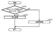
- FIG. 39 is a flowchart showing details of frequency conversion by the conversion unit in the third embodiment.
- FIG. 40 is a flowchart showing details of NN intra prediction parameter determination by the NN intra prediction parameter determination unit in the third embodiment.
- FIG. 41 is a flowchart showing details of NN inter prediction parameter determination by the NN inter prediction parameter determination unit in the third embodiment.
- FIG. 42 is a flowchart showing details of determination of an NN loop filter parameter by the NN loop filter parameter determination unit according to the third embodiment.
- FIG. 43 is a diagram illustrating the CU syntax in the third embodiment.
- FIG. 44 is a block diagram showing a configuration of the image decoding apparatus according to the fourth embodiment.
- FIG. 45 is a flowchart showing details of intra compensation block generation by the intra compensation unit and the NN process switching unit in the fourth embodiment.
- FIG. 46 is a flowchart showing details of inter compensation block generation by the inter compensation unit and the NN process switching unit in the fourth embodiment.
- FIG. 47 is a flowchart showing details of the in-loop filter by the in-loop filter unit and the NN process switching unit in the fourth embodiment.
- FIG. 48 is a flowchart showing details of inverse frequency conversion by the inverse conversion unit in the fourth embodiment.
- FIG. 49 is a block diagram showing a configuration of an image coding apparatus according to Embodiment 5.
- FIG. 50 is a flowchart showing details of the NN intra prediction parameter encoding in step S492 of FIG.
- FIG. 51 is a flowchart showing details of parameter non-reference type encoding in step S405 of FIG.
- FIG. 52 is a flowchart showing details of the parameter reference type encoding in step S406 of FIG.
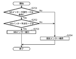
- FIG. 53 is a flowchart showing details of the parameter reference type layer number encoding in step S430 of FIG.
- FIG. 54 is a flowchart showing details of the parameter reference type node number encoding in step S447 of FIG.
- FIG. 50 is a flowchart showing details of the NN intra prediction parameter encoding in step S492 of FIG.
- FIG. 51 is a flowchart showing details of parameter non-reference type encoding in step S405 of FIG.
- FIG. 52 is a flowchart showing details of
- FIG. 55 is a flowchart showing details of the parameter reference type bias value encoding in step S449 of FIG.
- FIG. 56 is a flowchart showing details of parameter reference type weighting coefficient encoding in step S451 of FIG.
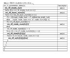
- FIG. 57 is a diagram illustrating the syntax of NN intra prediction parameter data according to Embodiment 5.
- FIG. 58 is a diagram illustrating the syntax of the parameter data of the NN intra prediction in the fifth embodiment.
- FIG. 59 is a flowchart showing overall processing of image coding by the image coding device according to the fifth embodiment.
- FIG. 60 is a block diagram showing the configuration of the image decoding apparatus in the sixth embodiment.
- FIG. 61 is a flowchart showing details of the NN intra prediction parameter decoding in step S602 of FIG. FIG.
- FIG. 62 is a flowchart showing details of parameter non-reference type decoding in step S505 in FIG.
- FIG. 63 is a flowchart showing details of the parameter reference type decoding in step S506 of FIG.
- FIG. 64 is a flowchart showing details of the parameter reference type hierarchy number decoding in step S540 of FIG.
- FIG. 65 is a flowchart showing details of the parameter reference type node number decoding in step S547 of FIG.
- FIG. 66 is a flowchart showing details of parameter reference type bias value decoding in step S549 of FIG.
- FIG. 67 is a flowchart showing details of parameter reference type weighting coefficient decoding in step S551 of FIG. FIG.
- FIG. 69A is a block diagram of an image encoding device according to an aspect of the present disclosure.
- FIG. 69B is a flowchart of an image encoding method according to an aspect of the present disclosure.
- FIG. 70A is a block diagram of an image decoding device according to an aspect of the present disclosure.
- FIG. 70B is a flowchart of an image decoding method according to an aspect of the present disclosure.
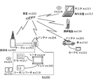
- FIG. 71 is an overall configuration diagram of a content supply system that realizes a content distribution service.
- FIG. 72 is an overall configuration diagram of a digital broadcasting system.
- FIG. 73 is a block diagram illustrating a configuration example of a television.
- FIG. 69A is a block diagram of an image encoding device according to an aspect of the present disclosure.
- FIG. 69B is a flowchart of an image encoding method according to an aspect of the present disclosure.
- FIG. 70A is a block diagram of an image decoding device according to an aspect of the
- FIG. 74 is a block diagram illustrating a configuration example of an information reproducing / recording unit that reads and writes information from and on a recording medium that is an optical disk.
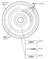
- FIG. 75 is a diagram illustrating a structure example of a recording medium that is an optical disk.
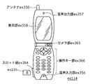
- FIG. 76A is a diagram illustrating an example of a mobile phone.
- FIG. 76B is a block diagram illustrating a configuration example of a mobile phone.
- FIG. 77 is a diagram showing a structure of multiplexed data.
- FIG. 78 is a diagram schematically showing how each stream is multiplexed in the multiplexed data.
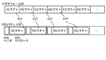
- FIG. 79 is a diagram showing in more detail how the video stream is stored in the PES packet sequence.
- FIG. 80 is a diagram showing the structure of TS packets and source packets in multiplexed data.
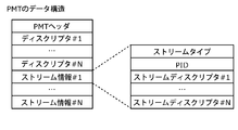
- FIG. 81 shows the data structure of the PMT.
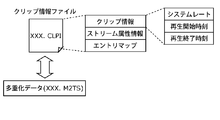
- FIG. 82 shows the internal structure of multiplexed data information.
- FIG. 83 shows the internal structure of stream attribute information.
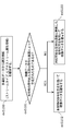
- FIG. 84 is a diagram showing steps for identifying video data.
- FIG. 85 is a block diagram illustrating a configuration example of an integrated circuit that implements the moving picture coding method and the moving picture decoding method according to each embodiment.
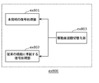
- FIG. 86 is a diagram showing a configuration for switching drive frequencies.
- FIG. 87 is a diagram showing steps for identifying video data and switching between driving frequencies.
- FIG. 88 is a diagram showing an example of a look-up table in which video data standards are associated with drive frequencies.
- FIG. 89A is a diagram illustrating an example of a configuration for sharing a module of a signal processing unit.
- FIG. 89B is a diagram illustrating another example of
- Non-patent Document 1 As an image coding standard, H.264 is used. H.264 / AVC (MPEG-4 AVC) is available, but the HEVC (High Efficiency Video Coding) standard (Non-patent Document 1) has been standardized as the next generation standard.
- the image encoding method in the HEVC standard includes a step of predicting an encoded image, a step of obtaining a difference between the predicted image and an encoding target image, a step of converting the difference image into a frequency coefficient, and a quantum of the frequency coefficient. And a step of arithmetically encoding the frequency coefficient and the prediction information, a step of decoding the encoded image, and an in-loop filter step of performing filter processing on the decoded image.
- the prediction step there are intra prediction to be predicted from within the screen and inter prediction to be predicted between the screens.
- Intra prediction, inter prediction, and in-loop filter are all realized by filters expressed by weighted linear sums of neighboring pixels, and fixed filter coefficients of several patterns are used for filter calculation.
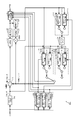
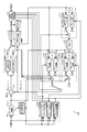
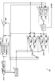
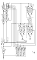
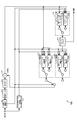
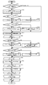
- FIG. 1 is a block diagram showing a configuration of an image encoding device according to the present embodiment.
- the image coding apparatus 100 includes a block dividing unit 101, a subtracting unit 102, a transforming unit 103, a quantizing unit 104, a variable length coding unit 105, an inverse transforming unit 106, an inverse quantizing unit 107, and an adding unit. 108, an NN parameter determination unit 109, an intra prediction unit 110, an inter prediction unit 111, a frame memory 112, and an in-loop filter unit 113.
- NN means a neural network.
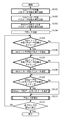
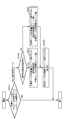
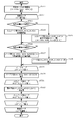
- FIG. 2 is a flowchart showing overall processing of image encoding by the image encoding device 100.
- the NN parameter determination unit 109 analyzes an encoding target image or an encoding target image group (sequence), and performs an NN intra prediction parameter switching unit, an NN inter prediction parameter switching unit, and an NN in-loop filter parameter switching unit (hereinafter referred to as “intra-loop filter parameter switching unit”). These are collectively referred to as NN parameter switching units) (S101, S102, S103).
- NN parameter switching units S101, S102, S103
- the NN parameter determination unit 109 obtains the pixel variance or average value of each block of the image, and sets the timing at which the block tendency differs in the coding order as the parameter switching timing.
- the NN parameter switching unit includes CU, CTU, slice, tile, picture, or GOP.
- the block division unit 101 divides the input image into blocks, and sequentially outputs the blocks to the subtraction unit 102, the intra prediction unit 110, and the inter prediction unit 111 (S104).
- the NN intra prediction parameter determination unit 109a determines whether or not the timing of the encoding target block is the NN intra prediction parameter switching timing, and if it is the NN intra prediction parameter switching timing, determines the NN intra prediction parameter (S105). , S106).
- the NN inter prediction parameter determination unit 109b determines whether the timing of the encoding target block is the NN inter prediction parameter switching timing, and determines the NN inter prediction parameter if it is the NN inter prediction parameter switching timing (S107). , S108).
- the NN loop filter parameter determination unit 109c determines whether or not the timing of the encoding target block is the NN loop filter parameter switching timing, and determines the NN loop filter parameter if it is the NN loop filter parameter switching timing. (S109, S110). Details regarding the determination of each parameter will be described later.
- the image encoding apparatus 100 encodes the block (S111), and repeats steps S105 to S111 until encoding of all the blocks in the encoding target image is completed (S112).
- the NN parameter switching unit may be the same between at least two of the NN intra prediction, the NN inter prediction, and the NN in-loop filter.
- the NN parameter switching unit may be a slice
- the NN parameter switching unit may be a picture.
- the parameter switching timing such as the above-described NN intra prediction parameter switching timing is such that a block included in a new NN parameter switching unit different from the NN parameter switching unit including the block encoded immediately before is encoded as an encoding target block. This is the timing when
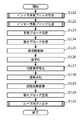
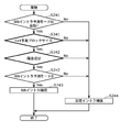
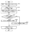
- FIG. 3 is a flowchart showing details of block coding in step S111 of FIG.
- the intra prediction unit 110 and the inter prediction unit 111 generate an intra prediction block and an inter prediction block (S121, S122). Details will be described later.
- the image coding apparatus 100 determines a prediction block by selecting either an intra prediction block or an inter prediction block (S123).
- the subtraction unit 102 subtracts the prediction block from the encoding target block to generate a difference block (S124).
- the conversion unit 103 performs frequency conversion on the difference block (S125), and the quantization unit 104 quantizes a plurality of frequency coefficients obtained by the frequency conversion (S126).
- the variable length coding unit 105 generates a code string by performing variable length coding on a plurality of quantized values obtained by quantization (S127).
- the inverse quantization unit 107 inversely quantizes a plurality of quantized values obtained by quantization (S128), and the inverse transform unit 106 performs inverse frequency transform on the plurality of frequency coefficients obtained by the inverse quantization. (S129).
- the adding unit 108 generates a restored block by adding the prediction block to the decoded difference block obtained by the inverse frequency transform (S130).
- the in-loop filter unit 113 performs an in-loop filter on the restored block and stores it in the frame memory 112 (S131). The in-loop filter will be described later.
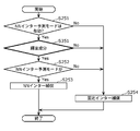
- FIG. 4 is a flowchart showing details of intra prediction block generation in step S121 of FIG.
- the intra prediction block generation is performed by the intra prediction unit 110.
- the fixed intra prediction unit 110b performs intra prediction using a fixed filter (S141). Since this is the same as the conventional HEVC, the description thereof is omitted.
- the NN intra prediction unit 110a determines whether or not the NN intra prediction mode is valid (S142), and performs intra prediction if it is valid (S143).
- the NN intra prediction unit 110a uses the parameters determined by the NN intra prediction parameter determination unit 109Aa for intra prediction. Although details will be described later, parameters exist for each class, the NN intra prediction unit 110a uses one class as one mode, has high prediction accuracy (the difference between the prediction image and the encoding target image is small), and prediction. By selecting and using a prediction mode with a small code amount of the mode identifier, a result of NN intra prediction is obtained.
- the intra prediction unit 110 compares the NN intra prediction evaluation value with the fixed intra prediction evaluation value (S144).
- the intra prediction unit 110 sets the NN intra prediction result to the intra prediction block (S145), and otherwise, sets the fixed intra prediction result to the intra prediction block. (S146).
- the evaluation value is a large value if the difference between the prediction image (intra prediction block) and the encoding target image (encoding target block) is small, and a parameter necessary for prediction (necessary weighting factor in the case of NN intra prediction). Alternatively, the smaller the code amount of the bias value or the like, the larger the value.
- FIG. 5 is a flowchart showing details of inter prediction block generation in step S122 of FIG. Steps S151 to S156 in the flowchart of FIG. 5 are substantially the same as steps S141 to S146 in the flowchart of intra prediction block generation in FIG. 4, and NN intra prediction and fixed intra prediction are replaced with NN inter prediction and fixed inter prediction. Therefore, the description is omitted.
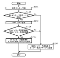
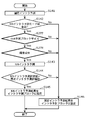
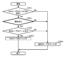
- FIG. 6 is a flowchart showing details of the in-loop filter in step S131 of FIG.
- Steps S161 to S164 in the flowchart of FIG. 6 are substantially the same as steps S141 to S144 in the flowchart of intra prediction block generation in FIG. 4, and the NN intra prediction and the fixed intra prediction are converted into the NN loop filter and the fixed loop filter. The description is omitted because it is simply replaced with.
- steps S165 and S166 in the flowchart of FIG. 6 the in-loop filter unit 113 stores the filter result with the better evaluation value in the frame memory 112.
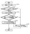
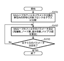
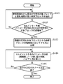
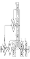
- FIG. 7 is a flowchart showing details of NN intra prediction parameter determination in step S106 of FIG.
- the NN intra prediction parameter determination unit 109a classifies each of the plurality of encoding target blocks in the NN intra prediction parameter switching unit into one of a plurality of classes (S171). For example, if the NN intra prediction parameter switching unit is a picture, the NN intra prediction parameter determination unit 109a classifies the block to be encoded in the picture. Classification is performed using block feature information. For example, the encoding target block is classified using pixel distribution or pixel distribution.
- the NN intra prediction parameter determination unit 109a determines NN intra prediction parameters for each classified class (S172). Details will be described with reference to FIGS. 10 and 13.
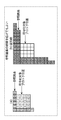
- FIG. 10 is a diagram showing a relationship between a reference pixel for NN intra prediction and a block to be encoded.
- One square represents one pixel.
- the NN intra prediction parameter determination unit 109a uses the upper adjacent pixel and the left adjacent pixel as the reference pixel.
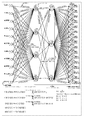
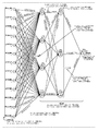
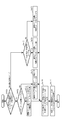
- FIG. 13 is a diagram illustrating an example of NN intra prediction.
- This NN intra prediction has a neural network configuration, and the eleven circles at the left end indicate reference pixels to be input, and correspond to reference pixels 0 to 10 in FIG. The 16 circles on the right end indicate prediction pixels to be output, and are prediction pixels corresponding to the numbers 0 to 15 of the encoding target block positions in FIG.
- the NN intra prediction parameter determination unit 109a determines the number of layers, the number of nodes, the weighting factor, and the bias value of the neural network illustrated in FIG.
- the number of layers is the number of layers in the mode (class) k, that is, the number of horizontal stages in FIG.
- the number of nodes is the number of nodes in the vertical direction of each layer.
- the number of nodes is the number of nodes in the 0th layer in the mode (class) k (in the example of FIG. 13, the number of nodes is 4).
- the weighting coefficient is a coefficient by which the input value of each node in the mode (class) k is multiplied.
- the weighting factor (nn_intra_w [k] [0] [0] [2]) is the number corresponding to the 0th node (n [k] [0] [0]) in the 0th hierarchy in the mode (class) k.
- a coefficient for multiplying the second input value (the value of the reference pixel 2 or the input node r2).
- the bias value (nn_intra_bias [k] [] []) is a value added to the weighted sum of the input values.
- the bias value (nn_intra_bias [k] [1] [1]) is an input value (n [k] [1] [1]) at the first node (n [k] [1] [1]) in the first layer in the mode (class) k. This value is added to the weighted sum of the input nodes n [k] [0] [0] to n [k] [0] [3].
- the output value of each node can be expressed by the following formula.
- Intra_pred_ref_pixel_num indicates the number of reference pixels, and is 11 in this example. Note that intra_pred_ref_pixel_num may be different depending on the mode (k) or the number of predicted pixels. Also, nn_intra_node_num indicates the number of nodes, and in this example, it is 4 in the first hierarchy and 3 in the second hierarchy. [K] indicates a class (mode). In the classification of step S171 in FIG. 7, when each block is divided into three classes, the NN intra-prediction parameter determination unit 109a constructs a network configuration as shown in FIG. ] Takes a value between 0 and 2.
- the NN intra prediction parameter determination unit 109a learns a pair of an encoding target block of the same class and its reference pixel (neighboring pixels) as teacher data, and uses the reference pixel as a reference data. A weighting factor and a bias value for generating (predicting) an encoding target block are calculated. More specifically, the NN intra prediction parameter determination unit 109a inputs a reference pixel, and uses an error back propagation method or the like so that a prediction pixel to be output is close to an encoding target block (an error is reduced).
- the weighting coefficient and the bias value are updated, and the weighting coefficient and the bias value are calculated so that the prediction error becomes the smallest for the input data (a pair group of the encoding target block of the same class and its surrounding pixels).
- the NN intra prediction parameter determination unit 109a performs such processing with a plurality of patterns in which the number of layers and the number of nodes are changed, and finds a combination of the number of layers, the number of nodes, the weighting factor, and the bias value with high prediction accuracy.
- the NN intra prediction parameter determination unit 109a Since the number of layers, the number of nodes, the weighting factor, and the bias value are encoded and incorporated in the code string, the NN intra prediction parameter determination unit 109a not only has the prediction accuracy but also the number of layers, the number of nodes, the weighting factor, and the bias. The optimum combination is derived in consideration of the code amount of the value.
- the NN intra prediction parameter determination unit 109a performs the process of step S172 on all classes (S173).
- FIG. 8 is a flowchart showing details of the NN inter prediction parameter determination in step S108 of FIG.
- the NN inter prediction parameter determination unit 109b extracts the reference block having the highest correlation from the reference image for each coding target block, and performs this on all the coding target blocks in the NN inter prediction parameter switching unit ( S181, S182).
- the NN inter prediction parameter determination unit 109b uses, for example, a sum of absolute differences of pixels for correlation calculation, and extracts a block having a small sum of absolute differences as a block having a high correlation.
- the NN inter prediction parameter determination unit 109b classifies each of the plurality of encoding target blocks into one of a plurality of classes according to the correlation between the encoding target block and the reference block (S183). .
- the NN inter prediction parameter determination unit 109b classifies a pixel having a small sum of absolute differences of values and a pixel having a large sum, or classifies using the variance or average of the differences for each pixel.
- the NN inter prediction parameter determination unit 109b determines the parameters of the NN inter prediction for each classified class (S184). Details will be described with reference to FIGS. 11 and 14.
- FIG. 11 is a diagram illustrating a relationship between a reference pixel for NN inter prediction and an encoding target block.
- One square represents one pixel.
- the NN inter prediction parameter determination unit 109b uses pixels in the 13-pixel reference image for prediction of one pixel of the encoding target block.
- the motion vector is information for indicating the block position having the highest correlation in the reference image.
- the NN inter prediction parameter determination unit 109b uses a peripheral pixel at a block position having the highest correlation as a reference pixel.
- FIG. 14 is a diagram illustrating an example of NN inter prediction.
- This NN network prediction has a neural network configuration as in the case of the NN intra prediction, and the 13 circles at the left end indicate input reference pixels and correspond to reference pixels 0 to 12 in FIG. One circle at the right end indicates a predicted pixel to be output, and is a predicted pixel corresponding to the encoding target block position number 0 in FIG.
- the NN inter prediction parameter determination unit 109b determines the number of layers, the number of nodes, the weighting factor, and the bias value of the neural network illustrated in FIG.
- the NN inter prediction parameter determination unit 109b receives 13 reference pixels and generates one prediction pixel.
- the NN inter prediction parameter determination unit 109b inputs the reference pixel position to the neural network in FIG. 14 while shifting the reference pixel by one pixel, and repeats 16 times to generate 16 prediction pixels. It will be.
- the NN inter prediction parameter determination unit 109b learns a pair of the encoding target pixel and the reference pixel of the same class as teacher data, and encodes the encoding target pixel from the reference pixel.
- the number of layers, the number of nodes, the weighting coefficient, and the bias value for generating (predicting) are calculated.
- the NN inter prediction parameter determination unit 109b performs the process of step S184 for all classes (S185).
- FIG. 9 is a flowchart showing details of determination of an NN in-loop filter parameter in step S110 of FIG.
- FIG. 12 is a diagram illustrating an example of the NN loop filter. Note that the processing of steps S191 to S193 performed by the NN in-loop filter parameter determination unit 109c in the flowchart of FIG. 9 is the same as the processing of steps S171 to S173 in the flowchart of NN intra prediction parameter determination shown in FIG. Therefore, the description of the flowchart of FIG. 9 is omitted. However, the NN in-loop filter parameter determination unit 109c uses 13 pixels around the pixel to be encoded as reference pixels as shown in FIG.
- the network configuration of the NN in-loop filter has a configuration as shown in FIG. 14 as in the NN inter prediction.
- the NN in-loop filter parameter determination unit 109c learns the reference pixel and the encoding target pixel as teacher data for each class, and generates the encoding target pixel from the reference pixel. A weight coefficient and a bias value are calculated.
- FIG. 15 is a diagram showing syntax related to SPS (sequence parameter set).
- nn_intra_pred_enabled_flag, nn_inter_pred_enabled_flag, and nn_ilf_enabled_flag are flags (valid / invalid information) indicating whether the NN intra prediction, the NN inter prediction, and the NN in-loop filter are valid, respectively. That is, the valid / invalid information is information for determining whether or not the process is valid in step S142 in FIG. 4, step S152 in FIG. 5, or step S162 in FIG. Also, such valid / invalid information may exist in the PPS, or may exist in a slice header or CTU (Coding
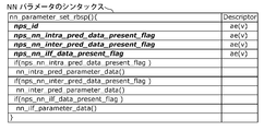
- FIG. 16 is a diagram illustrating the syntax of parameter information used in the NN intra prediction, the NN inter prediction, and the NN in-loop filter.
- nps_id is an identifier relating to this data set.
- nps_nn_intra_pred_data_present_flag, nps_nn_inter_pred_data_present_flag, and nps_nn_ilf_data_present_flag are parameters of NN intra prediction (nn_intra_pred_parameter_data ()), parameters of NN inter prediction (nn_inter_pred_parameter_data ()), parameters of NN This flag indicates whether or not When these flags are 1, the variable-length encoding unit 105 uses nn_intra_pred_parameter_data (), nn_inter_pred_parameter_data (), and nn_ilf_parameter_data () described later for NN intra prediction, NN inter prediction, and NN in-loop filter. Information on the number of layers, the number of nodes, weighting factors, and bias values (calculation parameters) is encoded.
- FIG. 17 is a diagram showing the syntax of PPS (Picture Parameter Set).
- PPS Picture Parameter Set
- the variable-length encoding unit 105 encodes pps_nps_id To do.
- the picture encoding apparatus 100 performs NN intra prediction, NN inter prediction, or NN intra-loop filtering using a calculation parameter of nps_id that matches pps_nps_id in a picture using this PPS.
- FIG. 18 is a diagram showing the syntax of the slice header.
- the variable-length encoding unit 105 encodes slice_nps_id To do.
- the image coding apparatus 100 performs NN intra prediction, NN inter prediction, or NN intra-loop filter using a calculation parameter of nps_id that matches slice_nps_id in a slice that uses this slice header. Note that the image encoding device 100 preferentially uses the value of slice_nps_id when pps_nps_id and slice_nps_id are different values.
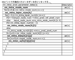
- FIG. 19 is a diagram showing the syntax of parameter data for NN intra prediction.
- nn_intra_mode_num indicates the number of NN intra prediction modes, and corresponds to the number of classes classified in step S171 in FIG.
- nn_intra_layer_num [k] indicates the number of layers of NN intra prediction, and [k] indicates the kth mode of NN intra prediction.
- nn_intra_node_num [k] [i] indicates the number of nodes in the i-th layer in the k-th mode.
- nn_intra_bias [k] [i] [j] indicates the bias value of the j-th node in the i-th layer of the k-th mode.
- variable-length encoding unit 105 encodes the parameter information (calculation parameters) of the network configuration in FIG. 13 with the syntax in FIG.
- FIG. 20 is a diagram illustrating the syntax of parameter data for NN inter prediction.
- FIG. 21 is a diagram illustrating the syntax of the parameter data of the filter in the NN loop.
- the variable length encoding unit 105 encodes the parameter information of the network configuration in FIG. 14 in the same manner as the NN intra prediction in FIG.
- FIG. 22 is a diagram illustrating the syntax of a CU (encoded block).
- the intra_pred_type is information indicating which of the NN intra prediction and the fixed intra prediction is used.
- the variable length encoding unit 105 encodes intra_pred_type indicating NN_INTRA_PRED when the evaluation value of NN intra prediction is large in S144 of FIG. 4, and encodes intra_pred_type indicating FIXED_INTRA_PRED when the evaluation value of fixed intra prediction is large. To do.
- the variable-length encoding part 105 does not encode intra_pred_type. In this case, the decoding side always operates to perform fixed intra prediction.
- variable length encoding unit 105 encodes the NN intra prediction mode as nn_intra_pred_mode.
- the variable length encoding unit 105 encodes a fixed intra prediction mode as fixed_intra_pred_mode.
- nn_intra_pred_mode is information indicating which class (mode) of operation parameter has been selected in the NN intra prediction of S143 in FIG. 4 and corresponds to [k] in FIG.
- fixed_intra_pred_mode corresponds to the prediction direction of HEVC intra prediction, and the fixed intra prediction unit 110b switches a plurality of sets of filter coefficients according to fixed_intra_pred_mode.
- inter_pred_type is information indicating whether NN inter prediction or fixed inter prediction is used.
- the variable length encoding unit 105 encodes inter_pred_type indicating NN_INTER_PRED when the evaluation value of NN inter prediction is large in S154 of FIG. 5, and encodes inter_pred_type indicating FIXED_INTER_PRED when the evaluation value of fixed inter prediction is large. To do.
- the variable-length encoding part 105 does not encode inter_pred_type. In this case, the decoding side always operates to perform fixed inter prediction.
- variable-length encoding unit 105 encodes the NN inter prediction mode as nn_inter_pred_mode.
- nn_inter_pred_mode is information indicating which class (mode) of the operation parameter is selected in the NN inter prediction of S153 in FIG. 5 and corresponds to [k] in FIG.
- prediction_unit () the variable-length encoding unit 105 encodes a motion vector and a reference image index as in HEVC.
- ilf_type is information indicating which of the NN loop filter and the fixed loop filter is used.
- the variable length encoding unit 105 encodes ilf_type indicating NN_ILF when the evaluation value of the filter in the NN loop is large in S164 of FIG. 6, and sets ilf_type indicating FIXED_ILF when the evaluation value of the filter in the fixed loop is large. Encode. Note that if the NN in-loop filter is not valid according to nn_ilf_enabled_flag, the variable-length encoding unit 105 does not encode ilf_type. In this case, the decoding side always operates so as to implement the fixed loop filter.
- variable length encoding unit 105 encodes the NN in-loop filter mode as nn_ilf_mode.
- nn_ilf_mode is information indicating which class (mode) of operation parameter is selected by the NN loop filter of S163 in FIG. 6, and corresponds to [k] in FIG.
- ⁇ Effect> it is possible to perform prediction pixel generation or in-loop filter specialized for the encoding target image, and it is possible to reduce prediction error or to perform in-loop filter processing close to the target image.
- Efficiency can be improved. More specifically, the relationship between the encoding target pixel and the reference pixel is learned by the neural network, so that the encoding target pixel can be generated from the reference pixel with high accuracy, and prediction accuracy is improved and noise is reduced. I can plan.
- intra prediction when an object that does not exist in surrounding pixels appears in the encoding target block, it is difficult to predict with conventional HEVC. However, with NN intra prediction, such data is also learned as teacher data in advance. Therefore, prediction is possible.
- the HEVC decimal pixel generation method is a general-purpose filtering process so that any input image can be handled. Depending on the input image, the decimal pixel prediction accuracy may be low. .
- the NN in-loop filter can construct a filter operation specialized for the input image, and can generate an image close to the original image with further reduced noise.
- the NN parameter switching unit can be set separately in the NN intra prediction, the NN inter prediction, and the NN in-loop filter, but may be all the same or partially the same.
- the NN parameter switching unit may be a slice unit, and in the NN intra-loop filter, the NN parameter switching unit may be a picture unit.
- the NN parameter switching unit may be a GOP that spans multiple pictures.
- the code amount of the identifier information for switching can be reduced, the number of types of NN parameters that must be encoded is reduced, and the code amount of the NN parameter is reduced. it can.
- the NN parameter determination unit 109 may input a plurality of pictures, learn from the blocks of those pictures, and determine the parameters of the NN, or use only representative image blocks. The parameter may be determined. By doing so, the learning time (parameter determination processing amount) can be reduced, and by determining the parameters using only the first picture for learning, encoding can be performed without waiting for subsequent picture inputs. You can start. As a result, the delay until the code string is output can be reduced.
- the validity / invalidity of the NN such as the NN intra prediction mode, the NN inter prediction mode, or the filter in the NN loop may be changed according to the profile, or may be designated by the user. Moreover, you may make it change according to the request
- FIG. 27 is a flowchart showing a process for switching the validity / invalidity of the NN according to the profile and the request.
- the image coding apparatus 100 performs the NN intra prediction, the NN inter prediction, and the NN loop when there is a real-time request and when the profile is for a low calculation amount.
- the inner filter may be disabled.
- An application having a real-time request is, for example, a TV phone, and conversely, an application having no real-time request is compression of movie content used for Internet distribution, for example.
- the NN prediction and the in-loop filter since it is necessary to learn the encoding target data in advance, it is necessary to scan the input image before encoding as in the case of 2-pass encoding. Therefore, the delay from the input of the image to the output of the code string is larger than that of the fixed filter.
- the NN inter prediction parameter determination unit 109b selects the encoding target block from any of a plurality of classes according to the correlation between the encoding target block and the reference block. Classified into classes. However, the NN inter prediction parameter determination unit 109b may classify the encoding target block using the decimal precision information of the motion vector, which is information for indicating a block position having a high correlation in the reference image.
- the NN inter prediction parameter determination unit 109b classifies the encoding target block into class 0, and the x component and y If both components have 1 ⁇ 2 pixel accuracy, the encoding target block may be classified into class 1.
- the learning data is classified into a plurality of classes, the parameters of the neural network are determined for each class, and the neural network of each class can be selected as one mode.
- the present disclosure is not limited to this, and only one mode may be used.
- each of the neural networks of the NN intra prediction, the NN inter prediction, and the NN in-loop filter may be set to one mode without being classified into a plurality of classes.
- the NN parameter determination unit 109 determines the number of layers, the number of nodes, the weighting factor, and the bias value as calculation parameters.
- the maximum value of the number of layers or the number of nodes may be set according to the request or profile of the application It is good also as a fixed value.
- FIG. 28 is a flowchart showing processing for setting parameters and the like according to a profile and a request.
- the NN parameter determination unit 109 sets the maximum number of layers in the neural network to 2 when profiling for applications requiring low real-time performance and low computational complexity. Then, the maximum number of nodes is set to 6.
- the amount of calculation for determining parameters of the image coding apparatus 100, and NN intra prediction, NN inter prediction, and NN in-loop filter processing in the image coding apparatus 100 and the image decoding apparatus The amount of calculation can be suppressed. As a result, it is useful for an application or a low-spec image decoding device that requires low delay.
- a user who operates the image encoding device 100 may set a limit value. By doing so, the user can control the encoding processing amount or the delay until the code string is output.
- the configuration example of the neural network shown in FIGS. 13 and 14 has a plurality of layers, it may have a single layer configuration, for example, a simple weighted linear sum configuration. By doing so, the configuration can be simplified and the processing amount can be reduced, and the parameter information to be encoded can be reduced. Depending on the input image, it may be more efficient to do so. In the minimum configuration, only the weighting coefficient for multiplying each reference pixel need be encoded.
- the image coding apparatus 100 performs preprocessing on reference pixels used when determining parameters, or reference pixels used for NN intra prediction, NN inter prediction, or NN in-loop filter, and then references them. Pixels may be input to the neural network.
- the preprocessing is a low-pass filter, a convolution operation, pooling, sampling, or the like. By doing so, the reference pixel becomes more generalized data, and the prediction accuracy or the in-loop filter performance may be improved.
- calculation parameters necessary for preprocessing may be separately included in the code string.
- the image coding apparatus 100 may use only a region where a prediction error or coding noise is likely to be large as learning data used for parameter determination. For example, only edge regions or regions with high complexity in the target image may be used as learning data. In a region where the prediction error or coding noise is small, the performance is often sufficient even with fixed intra prediction, fixed inter prediction, or fixed loop filter. Therefore, in that region, fixed intra prediction, fixed inter prediction, or a filter in a fixed loop may be used, and NN processing may be applied only to other regions where prediction errors or coding noise is likely to increase. .
- the reference pixels used for the NN intra prediction are not limited to 11 pixels in FIG.
- more reference pixels may be used as shown in FIG. 10B, and conversely, the reference pixels used for the NN intra prediction may be fewer than 11 pixels.
- Prediction accuracy may be increased by increasing the number of reference pixels (in a wide range).
- the parameter since the parameter amount necessary for the NN intra prediction tends to increase, the parameter may be switched depending on the NN intra prediction mode.
- 4x4 block size prediction and in-loop filter are described as an example, but the same processing is performed for 8x8 or 16x16 size as in HEVC, and the number of reference pixels increases as the block size increases. Needless to say.
- the reference pixels used for the NN inter prediction are not limited to the 13 pixels shown in FIG.
- more reference pixels may be used as shown in FIG.
- the shape composed of the reference pixel positions to be used may be a diamond shape as shown in FIG. 11A, or may be a square or a rectangle as shown in FIG.
- Prediction accuracy may be increased by increasing the number of reference pixels (in a wide range).
- switching may be performed depending on the NN inter prediction mode. By making the diamond shape, a pixel having a low correlation can be removed from the reference pixel while maintaining a certain range, and a necessary parameter amount can be reduced while maintaining the prediction performance.
- the reference pixels used for the NN loop filter are not limited to the 13 pixels shown in FIG.
- more reference pixels may be used as shown in FIG.
- the shape composed of the reference pixel positions to be used may be a diamond shape as shown in FIG. 12A, or may be a square or a rectangle as shown in FIG.
- In-loop filter performance may be improved by increasing the number of reference pixels (in a wide range).
- switching may be performed depending on the mode of the NN loop filter.
- a sigmoid function is used as f (x) of the activation function.
- the present disclosure is not limited to this, and the following function may be used.
- a table lookup using a lookup table is used, or the sigmoid function is replaced with an approximate expression having a smaller calculation amount. May be.
- a neural network is used.
- the present invention is not limited to this, and a simple weighted linear sum may be used as long as the prediction pixel or the in-loop filter result is calculated from the reference pixel.
- a nonlinear filter realized by combining primitive operations such as addition, subtraction, multiplication, or division may be used.
- all the reference pixels are coupled to all the nodes in the first layer, but this is not restrictive, and there may be reference pixels or nodes that are not coupled.
- a configuration in which the reference pixel is directly coupled to the second and subsequent nodes may be employed.
- the NN intra prediction, the NN inter prediction, and the NN in-loop filter valid flag are encoded by SPS, but may exist in PPS, or exist in slice header, CTU, or CU. May be.
- variable length coding unit 105 may collectively encode nn_parameter_set_rbsp () shown in FIG. 16 as a set of parameters to be used at the sequence head, GOP head, or picture head. Further, the image encoding apparatus 100 may use the NN parameter encoded immediately before, when the NN intra prediction, the NN inter prediction, or the NN intra-loop filter is used without using the nps_id. If encoding is performed collectively, variations in the code amount for each block can be suppressed, and rate control and the like can be easily performed. In addition, by specifying parameters using pps_nps_id or slice_nps_id shown in FIGS. 17 and 18, it is not necessary to encode duplicate parameters, which has an effect of reducing the amount of codes.
- NN intra prediction mode and the fixed intra prediction mode may be handled in a unified manner. Specifically, type information (intra_pred_type) indicating whether to use NN intra prediction or fixed intra prediction is not provided, and NN intra prediction may be used in a specific intra prediction mode.
- type information (intra_pred_type) indicating whether to use NN intra prediction or fixed intra prediction is not provided, and NN intra prediction may be used in a specific intra prediction mode.
- FIG. 23 shows a modified example of the syntax of the CU and shows a syntax in which the NN intra prediction mode is merged with the fixed intra prediction mode.
- FIG. 24 is a diagram illustrating an example of a relationship among intra_pred_mode, a prediction type, a fixed intra prediction mode, and an NN intra prediction mode in a modification of the CU syntax.
- FIG. 25 is a diagram illustrating another example of a relationship among intra_pred_mode, a prediction type, a fixed intra prediction mode, and an NN intra prediction mode in a modified example of the CU syntax.
- the intra prediction unit 110 uses fixed intra prediction when the intra prediction mode (intra_pred_mode) is 34 or less, and uses NN intra prediction when the intra prediction mode is 35 or more.
- the numerical value obtained by subtracting 35 from the intra prediction mode (intra_pred_mode) is the NN intra prediction mode (nn_intra_pred_mode).
- intra prediction type information (intra_pred_type) becomes unnecessary, and not only the amount of code but also a determination process becomes unnecessary.
- NN intra prediction may be used. In this case, mode 1 of fixed intra prediction is disabled, and mode 0 of NN intra prediction is enabled instead.
- NN intra prediction can be introduced without changing the total number of modes of intra prediction. That is, NN intra prediction can be introduced without increasing the code amount of the intra prediction mode. Moreover, this considers the case where some modes of fixed intra prediction become unnecessary by introduce
- Mode 0 of fixed intra prediction is a mode called Planar prediction
- mode 1 is a mode called DC prediction.
- DC prediction is easily selected in the case of a flat image. However, in the case of a flat image, a similar prediction image can be generated by Planar prediction, and in this case, the DC prediction mode becomes a redundant mode.
- it may be more effective to disable the DC prediction mode of fixed intra prediction and to use NN intra prediction when the DC prediction mode is designated.
- the inter prediction unit 111 may derive the NN inter prediction mode from the motion vector (MV).
- FIG. 26 is a diagram showing another modification of the CU syntax, in which an NN inter prediction mode is extracted with MV decimal precision.
- the inter prediction unit 111 derives the NN inter prediction mode from the MV decimal pixel accuracy information.
- the lower 2 bits of the MV indicate the fractional pixel position.
- the inter prediction unit 111 switches the NN inter prediction mode in accordance with the decimal pixel positions of the x component and the y component, and switches the configuration (parameter) of the neural network.
- Prediction calculation from neighboring pixels can be switched according to the decimal pixel position of MV, and it is not necessary to encode the NN inter prediction mode (nn_inter_pred_mode), and the code amount can be reduced. Further, since the prediction accuracy increases when the prediction calculation is switched according to the decimal pixel position of the MV, the prediction accuracy can be improved by this method.
- processing in this embodiment may be realized by software.
- the software may be distributed by downloading or the like. Further, this software may be recorded on a recording medium such as a CD-ROM and distributed. This also applies to other examples in this specification.
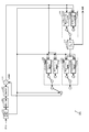
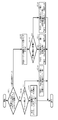
- FIG. 29 is a block diagram showing a configuration of the image decoding apparatus according to the present embodiment.
- An image decoding apparatus 200 includes a variable length decoding unit 201, an inverse quantization unit 202, an inverse transformation unit 203, an addition unit 204, an intra compensation unit 205, an inter compensation unit 206, a frame memory 207, and an in-loop filter.
- the unit 208 is provided.
- processing of these components will be described using a flowchart and the like.
- FIG. 30 is a flowchart showing the overall processing of image decoding by the image decoding apparatus 200.
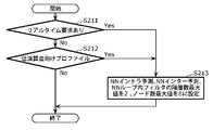
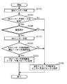
- the intra compensation unit 205 determines whether the timing of the decoding target block is the NN intra prediction parameter switching timing (S221). And if it is NN intra prediction parameter switching timing, the intra compensation part 205 will acquire the NN intra prediction parameter in a code sequence, and will set it to the NN intra compensation part 205a (S222). Similarly, the inter compensation unit 206 determines whether or not the timing of the decoding target block is the NN inter prediction parameter switching timing (S223). Then, if it is the NN inter prediction parameter switching timing, the inter compensation unit 206 acquires the NN inter prediction parameter in the code string and sets it in the NN inter compensation unit 206a (S224).
- the in-loop filter unit 208 determines whether the timing of the decoding target block is the NN in-loop filter parameter switching timing (S225). Then, if it is the NN loop filter parameter switching timing, the in-loop filter unit 208 acquires the NN loop filter parameter in the code string and sets it in the NN loop filter unit 208a (S226). Next, the image decoding apparatus 200 decodes the decoding target block (S227), and repeats the processing of steps S221 to S227 until decoding of all the blocks in the decoding target image is completed (S228).
- the parameter switching timing such as the above-described NN intra prediction parameter switching timing is such that a block included in a new NN parameter switching unit different from the NN parameter switching unit including the block decoded immediately before is decoded as a decoding target block. It is timing.
- FIG. 31 is a flowchart showing details of the block decoding in step S227 of FIG.
- variable length decoding unit 201 performs variable length decoding on the code string, and obtains a frequency converted and quantized block (S231).
- the inverse quantization unit 202 performs inverse quantization on the acquired block (S232), and the inverse transform unit 203 performs inverse frequency transform on the inversely quantized block (S233). .
- the image decoding apparatus 200 determines from the information in the code string whether the decoding target block is encoded by intra prediction or inter prediction (S234).
- the intra compensation unit 205 In the case of intra prediction, the intra compensation unit 205 generates an intra compensation block (S235), and in the case of inter prediction, the inter compensation unit 206 generates an inter compensation block (S236).
- the adding unit 204 generates a restoration block by adding any one of the intra compensation block and the inter compensation block and the result of the inverse frequency conversion (S237).
- the in-loop filter unit 208 performs an in-loop filter on the restored block, stores it in the frame memory 207, and outputs an image (S238).
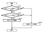
- FIG. 32 is a flowchart showing details of the intra compensation block generation in step S235 of FIG.
- the intra compensation unit 205 determines whether the NN intra prediction mode is valid or invalid, and whether the NN intra prediction mode is used for encoding using information in the code string (S241, S242).
- the NN intra compensation unit 205a when the NN intra prediction mode is valid and encoding is performed in the NN intra prediction mode, the NN intra compensation unit 205a generates an intra compensation block by performing NN intra compensation (S243). . Otherwise, the fixed intra compensation unit 205b generates an intra compensation block by performing fixed intra compensation (S244).
- the NN intra compensation block is generated using the reference pixel of FIG. 10 and the neural network of FIG.
- the parameters used in the NN intra compensation are parameters included in the code string set in step S222 in FIG.
- the syntax has the configuration shown in FIGS. 15 to 26 as in the first embodiment.
- the NN intra compensation unit 205a is a parameter specified by pps_nps_id or slice_nps_id as a parameter used in the NN intra compensation, and has a parameter (number of layers, nn_parameter_set_rbsp () having a nps_id that matches pps_nps_id or slice_nps_id.
- the number of nodes, weight coefficient, bias value) is acquired and used.
- FIG. 33 is a flowchart showing details of inter compensation block generation in step S236 of FIG. Steps S251 to S254 in the flowchart of FIG. 33 are substantially the same as steps S241 to S244 in the flowchart of intra-compensation block generation of FIG. 32, and only NN intra prediction and fixed intra prediction are replaced with NN inter prediction and fixed inter prediction. Therefore, explanation is omitted.
- the NN inter compensation block generation is realized using the reference pixel of FIG. 11 and the neural network of FIG. 14 as in the first embodiment.
- the parameters used in the NN inter compensation are parameters included in the code string set in step S224 in FIG.
- the syntax has the configuration shown in FIGS. 15 to 26 as in the first embodiment.
- the NN inter compensation unit 206a is a parameter specified by pps_nps_id or slice_nps_id as a parameter used in the NN inter compensation, and has parameters (number of layers, nn_parameter_set_rbsp () in the code string of nps_id that matches pps_nps_id or slice_nps_id.
- the number of nodes, weight coefficient, bias value) is acquired and used.
- the parameter exists for each NN inter prediction mode, and the NN inter compensation unit 206a switches the parameter using the NN inter prediction mode (nn_inter_pred_mode) included in the code string.
- FIG. 34 is a flowchart showing details of the in-loop filter in step S238 of FIG. Steps S261 to S264 in the flowchart of FIG. 34 are substantially the same as steps S241 to S244 in the flowchart of intra-compensation block generation in FIG. 32, and the NN intra prediction and the fixed intra prediction are applied to the NN loop filter and the fixed loop filter. The description is omitted because it is simply replaced.
- the NN in-loop filter is realized using the reference pixel of FIG. 12 and the neural network of FIG. Further, the parameters used in the NN loop filter are parameters included in the code string set in S226 of FIG.
- the syntax has the configuration shown in FIGS. 15 to 26 as in the first embodiment.
- the NN loop filter unit 208a is a parameter specified by pps_nps_id or slice_nps_id as a parameter to be used in the NN loop filter, and includes a parameter (hierarchy) in a code string of nn_parameter_set_rbsp () having nps_id that matches pps_nps_id or slice_nps_id. Number, number of nodes, weighting factor, bias value).
- a parameter exists for each mode of the NN loop filter, and the NN loop filter unit 208a switches the parameter using the NN loop filter mode (nn_ilf_mode) included in the code string.
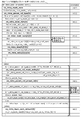
- the operation parameter of the nonlinear filter is encoded or decoded, and the target image is encoded or decoded using the operation parameter.
- This nonlinear filter is a filter other than a linear filter that is a weighted sum of a plurality of pixel values.
- the nonlinear filter is used in at least one of intra prediction, inter prediction, and in-loop filter in the method according to the first aspect. May be.
- the nonlinear filter includes a neural network, and at least a weighting factor between nodes is calculated as an operation parameter. It may be encoded or decoded.
- the operation parameter to be encoded or decoded may include information on the number of layers or the number of nodes. .
- the maximum value of the number of layers or the number of nodes may be defined by a profile in the method according to the fourth aspect.
- the switching information indicating whether to use a fixed parameter linear filter or the nonlinear filter is encoded.
- decoding may be performed to switch between using a linear filter and a nonlinear filter in accordance with the information.
- one or a plurality of modes are selected from a plurality of modes, and the mode using the nonlinear filter is used.
- the target image may be encoded or decoded using the nonlinear filter.
- the operation parameter of the nonlinear filter in at least one of a block, a slice, a tile, a picture, and a GOP May be switched.
- the nonlinear filter A calculation parameter may be encoded or decoded, and at least one of the calculation parameters may be designated by an identifier when the nonlinear filter is used.
- the validity / invalidity information of the nonlinear filter may be encoded or decoded in the method according to the first aspect.
- the validity / invalidity information of the nonlinear filter may be switched according to the profile in the method according to the tenth aspect.
- the nonlinear filter may be invalidated in an application having a low delay requirement.
- the method according to the first aspect includes a plurality of modes of the nonlinear filter, and encodes or decodes information indicating which mode is used.
- information indicating which mode is used may be extracted from the information in the code string.
- the operation parameter used for intra prediction is encoded or decoded.
- the calculation parameter may be any one of a linear filter and a non-linear filter.
- the intra prediction using the calculation parameter includes a single-layer or multi-layer neural network.
- at least a weighting factor between nodes may be encoded or decoded as an operation parameter.
- the operation parameter to be encoded or decoded may include information on the number of layers or the number of nodes. .
- the maximum value of the number of layers or the number of nodes may be defined by a profile.
- switching between intra prediction with a fixed parameter and intra prediction with the operation parameter is used.
- Information may be encoded or decoded, and switching between intra prediction using fixed parameters and intra prediction using calculation parameters may be switched according to the information.
- one or more modes are selected from among a plurality of modes using the calculation parameter.
- the target image may be encoded or decoded by the intra prediction using the calculation parameter.
- the calculation parameter for intra prediction in at least one of a block, a slice, a tile, a picture, and a GOP is provided. May be switched.
- the intra prediction is performed at at least one of a sequence head, a GOP head, and a picture head.
- at least one of the encoded or decoded operation parameters may be designated by an identifier and used.
- valid / invalid information of intra prediction using the calculation parameter may be encoded or decoded.
- the intra prediction valid / invalid information using the calculation parameter may be switched according to a profile.
- the method according to the fourteenth aspect there are a plurality of modes of intra prediction using the calculation parameter, and information indicating which mode is used May be extracted or information indicating which mode is used from the information in the code string.
- encoding is performed in an encoder that encodes an operation parameter of a linear filter or a nonlinear filter and encodes a target image using the operation parameter.
- the calculation parameter is determined by learning the target image as teacher data.
- the image encoding method according to the twenty-eighth aspect (3-1) of the present disclosure is the image encoding method according to the twenty-seventh aspect, wherein the image encoding method includes a plurality of modes using the calculation parameter,
- the learning data for each mode may be determined based on the above characteristics, and the calculation parameter may be determined for each mode.
- FIG. 35 is a block diagram showing the configuration of the image coding apparatus according to the present embodiment.
- the image coding apparatus 300 includes components other than the conversion unit 103 and the NN parameter determination unit 109A in the image coding apparatus 100 according to the first embodiment. Furthermore, the image coding apparatus 300 includes a conversion unit 103A and an NN parameter determination unit 109A instead of the conversion unit 103 and the NN parameter determination unit 109, and also includes an NN process switching unit 115.
- the overall flow of image coding by the image coding apparatus 300 and the flow of block coding are almost the same as the flows shown in FIGS. 2 and 3 in the first embodiment.
- the block division unit 101 in the image coding apparatus 300 divides the input image into blocks of several sizes such as 4 ⁇ 4 blocks, 8 ⁇ 8 blocks, 16 ⁇ 16 blocks, and 32 ⁇ 32 blocks in the block division (S104) in FIG.
- the block dividing unit 101 divides the block into blocks of any size using features such as the size of the object in the input image or the complexity of the pixel value.
- the image coding apparatus 300 may experimentally perform prediction or variable length coding, and the block division unit 101 may divide the block into blocks having a good coding performance.
- the image coding apparatus 300 performs block coding including prediction and the like on blocks of a plurality of types.
- FIG. 36 is a flowchart showing details of intra prediction block generation by the intra prediction unit 110 and the NN process switching unit 115.
- the flow of intra prediction block generation by the intra prediction unit 110 in the third embodiment is almost the same as the flow shown in FIG. 4 of the first embodiment, but the difference between the present embodiment and the first embodiment is that This is a condition for performing NN intra prediction (S143).
- the intra prediction unit 110 performs the NN intra prediction by the NN intra prediction unit 110a only when the prediction block size is 4 ⁇ 4 and the prediction is performed on the luminance component under the control of the NN process switching unit 115 ( S277, S278). Otherwise, the intra prediction unit 110 always performs the fixed intra prediction by the fixed intra prediction unit 110b.
- the NN process switching unit 115 determines whether or not the predicted block size is 4 ⁇ 4 (S277) and determines whether or not the prediction target is a luminance component (S278). Then, the NN process switching unit 115 instructs the intra prediction unit 110 to switch to the NN intra prediction only when the prediction block size is 4 ⁇ 4 and only when prediction is performed on the luminance component.
- FIG. 37 is a flowchart showing details of inter prediction block generation by the inter prediction unit 111 and the NN process switching unit 115.
- the flow of inter prediction block generation by the inter prediction unit 111 in the third embodiment is almost the same as the flow shown in FIG. 5 of the first embodiment, but the difference between the present embodiment and the first embodiment is that This is a condition for performing NN inter prediction (S153).
- the inter prediction unit 111 performs the NN inter prediction by the NN inter prediction unit 111a only by the prediction with respect to the luminance component under the control of the NN process switching unit 115 (S288). Otherwise, the inter prediction unit 111 always performs fixed inter prediction by the fixed inter prediction unit 111b.
- the NN process switching unit 115 determines whether the prediction target is a luminance component (S288). Then, the NN process switching unit 115 instructs the inter prediction unit 111 to switch to the NN inter prediction only in the case of prediction with respect to the luminance component.
- FIG. 38 is a flowchart showing details of the in-loop filter by the in-loop filter unit 113 and the NN process switching unit 115.
- the flow of the in-loop filter by the in-loop filter unit 113 in the third embodiment is almost the same as the flow shown in FIG. 6 of the first embodiment, but the difference between the present embodiment and the first embodiment is that This is a condition for performing the NN loop filter (S163).
- the in-loop filter unit 113 performs the NN in-loop filter by the NN loop filter unit 113a only by the in-loop filter for the luminance component under the control of the NN process switching unit 115 (S298). Otherwise, the in-loop filter unit 113 always performs a fixed loop filter by the fixed loop filter unit 113b.
- the NN process switching unit 115 determines whether or not the prediction target is a luminance component (S298). Then, the NN process switching unit 115 instructs the in-loop filter unit 113 to switch to the NN in-loop filter only in the case of prediction for the luminance component.
- FIG. 39 is a flowchart showing details of frequency conversion by the conversion unit 103A.
- the conversion unit 103A determines whether the prediction block selected in the prediction block determination (S123 in FIG. 3) is a block generated by NN intra prediction or NN inter prediction (S301). If the block is generated by any prediction, the KL conversion unit 103Aa performs frequency conversion by KL conversion (Karunen-Loeve conversion) (S302). In other cases, the fixed conversion unit 103Ab performs frequency conversion (fixed conversion) using a fixed conversion matrix such as discrete cosine conversion as in HEVC (S303). The KL conversion is conversion for changing the conversion matrix for each image.
- FIG. 40 is a flowchart showing details of NN intra prediction parameter determination by the NN intra prediction parameter determination unit 109Aa.
- FIG. 41 is a flowchart showing details of NN inter prediction parameter determination by the NN inter prediction parameter determination unit 109Ab.
- FIG. 42 is a flowchart showing details of the NN in-loop filter parameter determination by the NN in-loop filter parameter determination unit 109Ac.
- the flow for determining each parameter in the third embodiment is almost the same as the flow shown in FIGS. 7, 8, and 9 of the first embodiment.
- learning data is used.
- the data used for is different.
- the NN intra prediction parameter determination unit 109Aa learns by classifying the luminance component encoding target blocks of 4 ⁇ 4 size into classes as learning data used for NN intra prediction parameter determination (S311).
- the NN inter prediction parameter determination unit 109Ab targets a luminance component encoding target block as learning data used for NN inter prediction parameter determination (S321, S323).
- the NN loop filter parameter determination unit 109Ac targets the luminance component encoding target block as learning data used for the NN loop filter parameter determination (S331).
- the syntax configuration in the third embodiment is different from that in the first embodiment only in the CU syntax.
- FIG. 43 is a diagram showing the CU syntax in the present embodiment.
- the variable-length encoding unit 105 uses information (intra_pred_type) indicating whether to use NN intra prediction or fixed intra prediction, NN intra prediction is valid (nn_intra_pred_enabled_flag is 1), and the prediction block size is 4 ⁇ 4. Only in the case of. Otherwise, the image encoding device 300 operates to use fixed intra prediction. That is, the NN intra prediction can be used only when the prediction block size is 4 ⁇ 4.
- Fixed_intra_pred_mode_chroma indicates a prediction mode of fixed intra prediction of a color difference component, and in the case of a color difference component, only a mode of fixed intra prediction can be specified.
- nn_intra_pred_parameter_data is a 4 ⁇ 4 size prediction block and NN intra prediction parameter for luminance component, and no other parameters (prediction block or color difference component of 8 ⁇ 8 size or more) exist (encode).
- nn_inter_pred_parameter_data is a parameter of NN inter prediction for luminance components
- nn_ilf_parameter_data is a parameter of an NN loop filter for luminance components
- the code amount of the parameter used by NN intra prediction can be reduced. More specifically, the NN intra prediction is performed only on the 4 ⁇ 4 size prediction block. That is, since the NN intra prediction is not used in a prediction block of 8 ⁇ 8 size or more, a parameter for it is not necessary. In general, a large prediction block size is often selected in a flat region, and in that case, it is often possible to reduce a prediction residual even in intra prediction with a fixed parameter. Therefore, it is less necessary to use NN intra prediction with a large prediction block size than with a small prediction block size.
- the number of neighboring pixels is large in a large prediction block size, it is generally difficult to increase the prediction accuracy unless the number of reference pixels is increased.
- the amount of parameters for NN intra prediction increases.
- a small prediction block size is often selected in a region with high complexity, and in a region with high complexity, prediction errors tend to be large in intra prediction with fixed parameters.
- the number of adjacent neighboring pixels is small, so there is a possibility that the prediction accuracy can be increased with a small number of reference pixels. Therefore, by enabling NN intra prediction only with a small prediction block size and encoding only a parameter for a small prediction block size, the amount of parameter data can be reduced while suppressing a decrease in prediction performance. The encoding efficiency can be improved.
- the calculation amount (processing time) of the image coding apparatus 300 that determines the parameters can be reduced.
- the NN intra prediction, the NN inter prediction, and the NN in-loop filter are performed only on the luminance component signal. That is, since the NN intra prediction, the NN inter prediction, and the NN intra-loop filter are not used for the color difference component signal, parameters for the NN intra prediction, the NN inter prediction, and the NN inter prediction are not necessary.
- the complexity of the color difference component of the image is small, and the NN intra prediction, the NN inter prediction, and the NN intra-loop filter that are fixed parameters can often reduce the prediction residual or reduce the noise.
- the NN intra prediction, the NN inter prediction, and the NN in-loop filter for the color difference component it is less necessary to use the NN intra prediction, the NN inter prediction, and the NN in-loop filter for the color difference component than the luminance component. Therefore, by enabling the NN intra prediction, the NN inter prediction, and the NN in-loop filter only for the luminance component and encoding only the parameters for the luminance component, the parameters can be suppressed while suppressing a decrease in prediction accuracy and an increase in noise. The amount of data can be reduced, and the encoding efficiency can be improved. Further, since the NN intra prediction, the NN inter prediction, and the NN in-loop filter for the color difference component are not necessary, the calculation amount (processing time) of the image coding apparatus 300 that determines the parameters can be reduced.
- the tendency of the prediction residual is different from that when the fixed prediction is used.
- the prediction error suddenly increases when an object that does not exist in surrounding pixels appears in the encoding target block.
- the NN intra prediction if a neural network is constructed so as to cover such a case, there are few cases where the prediction error suddenly increases. Therefore, when NN intra prediction or NN inter prediction is used, the frequency conversion method is switched, and when NN prediction is used, the coding efficiency is improved by using conversion of a method suitable for the prediction residual. be able to.
- KL conversion is used.
- the present invention is not limited to this.
- NN intra prediction or NN inter prediction a conversion method different from that used when fixed prediction is used may be used. Conversion using a fixed conversion matrix may be used. Further, parameters such as a transformation matrix used in the transformation such as KL transformation may be separately encoded.
- the conversion is switched when NN intra prediction or NN inter prediction is used. However, the conversion may be switched only when NN intra prediction is used, or only when NN inter prediction is used. May be.
- NN intra prediction is used only when the prediction block size is 4x4, but this is not the case.
- NN intra prediction is permitted for a size of 8x8 or smaller, and NN intra prediction is prohibited for a size of 16x16 or larger. May be.
- the inverse conversion unit 106 in the present embodiment performs an inverse conversion corresponding to the conversion of the conversion unit 103A.
- FIG. 44 is a block diagram showing a configuration of the image decoding apparatus according to the present embodiment.
- the image decoding apparatus 400 includes components other than the inverse transform unit 203 in the image decoding apparatus 200 according to the second embodiment. Furthermore, the image decoding apparatus 400 includes an inverse transform unit 203A instead of the inverse transform unit 203 and an NN process switching unit 210.
- the overall flow of image decoding by the image decoding apparatus 400 and the flow of block decoding are substantially the same as the flows shown in FIGS. 30 and 31 in the second embodiment.
- the decoding target blocks in the image decoding apparatus 400 include blocks of several sizes such as 4 ⁇ 4 blocks, 8 ⁇ 8 blocks, 16 ⁇ 16 blocks, and 32 ⁇ 32 blocks.
- the image decoding apparatus 400 determines the block size using information in the code string. Further, the image decoding apparatus 400 performs block decoding including prediction and the like on blocks of a plurality of types of sizes.
- FIG. 45 is a flowchart showing details of intra compensation block generation by the intra compensation unit 205 and the NN process switching unit 210.
- the flow of intra-compensation block generation by the intra-compensation unit 205 in the fourth embodiment is almost the same as the flow shown in FIG. 32 of the second embodiment, but the difference between the present embodiment and the second embodiment is that This is a condition for performing NN intra compensation (S243).
- the intra compensation unit 205 performs the NN intra compensation by the NN intra compensation unit 205a only when the predicted block size is 4 ⁇ 4 and only for the luminance component under the control of the NN process switching unit 210 ( S341, S342). Otherwise, the intra compensation unit 205 always performs fixed intra compensation by the fixed intra compensation unit 205b.
- the NN process switching unit 210 determines whether or not the predicted block size is 4 ⁇ 4 (S341), and determines whether or not the compensation target is a luminance component (S342). Then, the NN processing switching unit 210 instructs the intra compensation unit 205 to switch to the NN intra compensation only when the predicted block size is 4 ⁇ 4 and only when the luminance component is compensated.
- FIG. 46 is a flowchart showing details of inter compensation block generation by the inter compensation unit 206 and the NN processing switching unit 210.
- the flow of inter compensation block generation by the inter compensation unit 206 in the fourth embodiment is almost the same as the flow shown in FIG. 33 of the second embodiment, but the difference between the present embodiment and the second embodiment is that This is a condition for performing NN inter compensation (S253).
- the inter-compensation unit 206 performs NN inter-compensation by the NN inter-compensation unit 206a only by compensation for the luminance component under the control of the NN process switching unit 210 (S351). Otherwise, the inter compensation unit 206 always performs fixed inter compensation by the fixed inter compensation unit 206b.
- the NN process switching unit 210 determines whether or not the compensation target is a luminance component (S351). Then, the NN processing switching unit 210 instructs the inter compensation unit 206 to switch to the NN inter compensation only when the luminance component is compensated.
- FIG. 47 is a flowchart showing details of the in-loop filter by the in-loop filter unit 208 and the NN process switching unit 210.
- the flow of the in-loop filter by the in-loop filter unit 208 in the fourth embodiment is substantially the same as the flow shown in FIG. 34 of the second embodiment, but the difference between the present embodiment and the second embodiment is that This is a condition for performing the NN loop filter (S263).
- the in-loop filter unit 208 performs the NN in-loop filter by the NN loop filter unit 208a only by the in-loop filter for the luminance component under the control of the NN processing switching unit 210 (S361). Otherwise, the in-loop filter unit 208 always implements the fixed loop filter by the fixed loop filter unit 208b.
- the NN process switching unit 210 determines whether or not the in-loop filter target is a luminance component (S361).
- the NN processing switching unit 210 instructs the in-loop filter unit 208 to switch to the NN in-loop filter only in the case of the in-loop filter for the luminance component.
- FIG. 48 is a flowchart showing details of inverse frequency conversion by the inverse conversion unit 203A.
- the inverse transform unit 203A determines whether a prediction block has been generated by NN inter prediction or NN intra prediction from information in the code string (S371). If the block is generated by any one of the predictions, the inverse KL transform unit 203Aa performs inverse frequency transform by inverse KL transform (Karunen-Loeve transform) (S372). In other cases, the inverse fixed transform unit 203Ab performs inverse frequency transform (inverse fixed transform) using a fixed transform matrix such as inverse discrete cosine transform as in HEVC (S373).
- an operation parameter used for intra prediction is encoded or decoded.
- intra prediction using the calculation parameter is performed only when the prediction block size of intra prediction is equal to or smaller than a specific size. In the case of other prediction block sizes, fixed parameter intra prediction may be performed.
- the conversion or inverse conversion method may be switched.
- the conversion using a changeable transformation matrix is possible when intra prediction using the calculation parameter is used.
- inverse transformation may be performed.
- the operation parameter of the nonlinear filter is encoded or decoded, and the target image is encoded or decoded using the operation parameter. To do.
- the luminance component uses the nonlinear filter.
- the color difference component may be encoded or decoded using a linear filter.
- the nonlinear filter is used in at least one of intra prediction and inter prediction, and the prediction block is When creating using a non-linear filter, the conversion or inverse conversion method may be switched.
- a changeable transformation matrix is used. Conversion or reverse conversion may be performed.
- FIG. 49 is a block diagram showing the configuration of the image coding apparatus according to the present embodiment.
- the image coding apparatus 500 includes each component of the image coding apparatus 100 according to the first embodiment, and further includes an NN parameter coding unit 120.
- FIG. 59 is a flowchart showing overall processing of image encoding by the image encoding device 500.
- the image coding apparatus 500 performs steps S101 to S112 included in the flow shown in FIG. 2 of the first embodiment, and further performs steps S491, S492, S493, and S494. That is, in Embodiment 5, the image coding apparatus 500 performs any one of steps S492 to S494 at the time of parameter switching timing of any one of NN intra prediction, NN inter prediction, and NN in-loop filter (S491). I do.
- NN parameter encoding section 120 performs special NN intra prediction parameter encoding, NN inter prediction parameter encoding, or NN intra-loop filter parameter encoding that is different from that in the first embodiment.
- FIG. 50 is a flowchart showing details of the NN intra prediction parameter encoding in step S492 of FIG.
- the NN parameter encoding unit 120 encodes the number of prediction modes (nn_intra_mode_num) of NN intra prediction (S401).
- the NN parameter encoding unit 120 performs the processing of steps S403 to S407 in each prediction mode (S402).
- k represents a prediction mode to be processed, and is a variable that increases by 1 from 0 to “number of prediction modes ⁇ 1”.
- the NN parameter encoding unit 120 determines a parameter reference type of the prediction mode k, a parameter to be referred to, and the like (S407).
- the parameter reference type is information on how to encode the NN intra prediction parameter, and there are three types.
- the first type refers to a method of referring to parameters of other prediction modes and encoding the difference between them (mode reference type).
- the second type refers to a method of referring to the information of the previous hierarchy or the previous node and encoding the difference with the information (previous reference type).
- the third type is a method of directly encoding a value without referring to anything (non-reference type).
- the NN parameter encoding unit 120 determines the parameter reference type, and in the case of the mode reference type, the reference mode information (nn_intra_param_ref_mode) indicating which prediction mode parameter is to be used, and whether to use the preset. Information (preset use mode ON / OFF) and a preset ID (nn_intra_param_ref_preset_id) indicating which preset is used when a preset parameter is used are determined.
- a parameter having the most similar parameter to the NN intra prediction parameter to be encoded may be selected, or a parameter having the smallest code amount may be selected by experimentally encoding.
- the NN parameter encoding unit 120 encodes the parameter reference type (nn_intra_param_ref_type [k]) of the prediction mode k determined in step S407 (S403).
- the NN parameter encoding unit 120 determines whether or not the parameter reference type is a non-reference type (S404). If the parameter reference type is a non-reference type, the parameter non-reference type encoding is performed (S405). On the other hand, when the type is not a non-reference type (in the case of a mode reference type or a previous reference type), the NN parameter encoding unit 120 performs parameter reference type encoding (S406).
- the mode (reference mode) including the parameter to be referred to indicated by the reference mode information is limited to the same structure as the prediction mode k. That is, the reference mode and the prediction mode k have the same number of layers, the same number of nodes, the same number of reference pixels, and the same number of output pixels.
- the reference mode information (nn_intra_param_ref_mode) indicating the reference mode indicates how many modes before the prediction mode k is the reference mode, and its default value is zero.
- FIG. 51 is a flowchart showing details of parameter non-reference type encoding in step S405 of FIG.
- the NN parameter encoding unit 120 encodes the number of layers (nn_intra_layer_num [k]) of the prediction mode k (S411), and repeats the subsequent processing for the number of layers (S412).
- i represents a hierarchy to be processed, and is a variable that increases by 1 from 0 to “number of hierarchies ⁇ 1”.
- the NN parameter encoding unit 120 determines whether or not the hierarchy i is the first hierarchy (S413), and if it is the first hierarchy, sets the reference pixel number as the input node number (input_node_num) ( S414). On the other hand, if it is not the first layer, the NN parameter encoding unit 120 sets the number of nodes in the immediately preceding layer (nn_intra_node_num [k] [i-1]) as the number of input nodes (input_node_num) (S415). Referring to FIG.
- the NN parameter encoding unit 120 determines whether or not the layer i is the last layer (S416). If the layer i is the last layer, the NN parameter encoding unit 120 predicts the number of nodes (nn_intra_node_num [k] [i]). The number of pixels (number of output pixels) (16 in the example of FIG. 13) is set (S417). On the other hand, if it is not the last layer, the NN parameter encoding unit 120 encodes the number of nodes (S418).
- the NN parameter encoding unit 120 encodes the bias value (nn_intra_bias [k] [i] [j]) for the number of nodes (S419, S420), and the weight coefficient (nn_intra_w) for the number of nodes and the number of input nodes.
- [k] [i] [j] [m]) are encoded (S421, S422).
- j represents a node to be processed, and is a variable that increases by 1 from 0 to “the number of nodes in hierarchy i ⁇ 1”.
- m represents an input node to be processed, and is a variable that increases by 1 from 0 to “the number of input nodes of node j of layer i ⁇ 1”.
- An input node is a node that inputs a value to a processing target node. For example, there are 12 input nodes n [k] [0] [0] in FIG.
- FIG. 52 is a flowchart showing details of the parameter reference type encoding in step S406 of FIG.
- the NN parameter encoding unit 120 determines whether or not the parameter reference type of the prediction mode k is a mode reference type (S431), and if it is a mode reference type, further determines whether or not it is a preset use mode. If it is the preset use mode, 0 is set to the reference mode delta (S433). Then, the NN parameter encoding unit 120 encodes the reference mode delta (S436), and encodes a preset ID to be used (S436, S437).
- the NN parameter encoding unit 120 calculates the reference mode delta by subtracting the reference mode (nn_intra_param_ref_mode) from k (S434), and then encodes the reference mode delta (S435). As described here, whether the preset use mode is ON or OFF is not directly encoded. If the reference mode delta is 0, the image decoding apparatus can determine that the preset use mode is ON. If the parameter reference type is the immediately preceding reference type (No in S431), the NN parameter encoding unit 120 does not perform the processes in steps S432 to S437.
- the NN parameter encoding unit 120 encodes the number of layers with the parameter reference type (S440). Details will be described later.
- the NN parameter encoding unit 120 repeats the following process for the number of layers (S441).
- i represents a hierarchy to be processed, and is a variable that increases by 1 from 0 to “number of hierarchies ⁇ 1”.
- the NN parameter encoding unit 120 determines whether or not the hierarchy i is the first hierarchy (S442), and if it is the first hierarchy, sets the number of reference pixels in the number of input nodes (input_node_num). (S443). On the other hand, if it is not the first layer, the NN parameter encoding unit 120 sets the number of nodes in the immediately preceding layer (nn_intra_node_num [k] [i-1]) as the number of input nodes (input_node_num) (S444).
- the NN parameter encoding unit 120 determines whether or not the hierarchy i is the last hierarchy (S445), and if it is the last hierarchy, predicts the number of nodes (nn_intra_node_num [k] [i]). The number of pixels (number of output pixels) is set (S446). On the other hand, if it is not the last layer, the NN parameter encoding unit 120 encodes the number of nodes with the parameter reference type (S447). Details of the encoding of the number of nodes will be described later.
- the NN parameter encoding unit 120 encodes the bias value for the number of nodes (S448, S449), and encodes the number of nodes and the weighting factor for the number of input nodes with the parameter reference type (S450, S451).
- j represents a node to be processed, and is a variable that increases by 1 from 0 to “the number of nodes in hierarchy i ⁇ 1”.
- m represents an input node to be processed, and is a variable that increases by 1 from 0 to “the number of input nodes of node j of layer i ⁇ 1”.
- FIG. 53 is a flowchart showing details of the parameter reference type layer number encoding in step S440 of FIG.
- the NN parameter encoding unit 120 determines whether or not the parameter reference type of the prediction mode k is the mode reference type (S431), and if it is not the mode reference type (if it is the immediately preceding reference type), the layer of the prediction mode k The number is encoded (S465). If it is a mode reference type, the image decoding apparatus can obtain the number of layers from the parameter of the prediction mode to be referred to or the preset parameter, so the NN parameter encoding unit 120 does not encode the number of layers.
- FIG. 54 is a flowchart showing details of the parameter reference type node number encoding in step S447 of FIG.
- the NN parameter encoding unit 120 determines whether or not the parameter reference type of the prediction mode k is the mode reference type (S431), and if it is not the mode reference type (if it is the immediately preceding reference type), the layer of the prediction mode k
- the node number delta of i is encoded (S462 to S465).
- the NN parameter encoding unit 120 determines whether or not the hierarchy i is the first hierarchy (S462).
- the NN parameter encoding unit 120 subtracts the number of nodes in the layer i in the prediction mode k from the number of reference pixels to obtain the number of nodes delta in the layer i in the prediction mode k.
- the NN parameter encoding unit 120 subtracts the number of nodes in the layer i in the prediction mode k from the number of nodes in the previous layer, thereby obtaining the node in the layer i in the prediction mode k.
- a number delta is calculated (S464), and the node number delta is encoded (S465).
- FIG. 55 is a flowchart showing details of the parameter reference type bias value encoding in step S449 of FIG.
- the NN parameter encoding unit 120 calculates a bias value delta by subtracting the bias value of the node j of the layer i in the prediction mode k from the reference bias value (S478), and calculates the value as the value of the layer i of the prediction mode k. It is encoded as the bias value delta of the node j (S479).
- the reference bias value varies depending on conditions. That is, the NN parameter encoding unit 120 determines whether or not the parameter reference type of the prediction mode k is a mode reference type (S431), and if it is a mode reference type, further determines whether or not it is a preset use mode ( S432).
- the NN parameter encoding unit 120 sets the bias value of the node j of the hierarchy i in the preset of the preset ID as the reference bias value. (S473). Conversely, even if the parameter reference type is the mode reference type, if the preset use mode is OFF, the NN parameter encoding unit 120 refers to the bias value of the node j in the hierarchy i in the prediction mode (reference mode) to be referred to. The bias value is set (S474).
- the NN parameter encoding unit 120 determines whether or not the node j is the first node in the hierarchy i (S475). If it is a node, the default bias value of layer i is set as the reference bias value (S476). On the other hand, if it can be the first node, the NN parameter encoding unit 120 sets the bias value of the immediately preceding node as the reference bias value (S477).
- the first node is a node of n [k] [x] [0] as described with reference to FIG. 13, and is a node at the top in each hierarchy.
- the immediately preceding node is a node that is one level higher in the same hierarchy in FIG. 13, and the immediately preceding node of n [k] [x] [1] is n [k] [x] [0]. is there.
- the default bias value is a bias value defined in advance.
- FIG. 56 is a flowchart showing details of parameter reference type weighting coefficient encoding in step S451 of FIG.
- the NN parameter encoding unit 120 calculates the weighting factor delta by subtracting the weighting factor of the input node m of the node j of the layer i in the prediction mode k from the reference weighting factor (S488), and uses the value as the prediction mode. Encoding is performed as a weighting coefficient of the input node m of the node j of the hierarchy i of k (S489).
- the reference weighting factor varies depending on conditions. That is, the NN parameter encoding unit 120 determines whether or not the parameter reference type of the prediction mode k is a mode reference type (S431), and if it is a mode reference type, further determines whether or not it is a preset use mode ( S432).
- the NN parameter encoding unit 120 calculates the weight coefficient of the input node m of the node j of the hierarchy i in the preset of the preset ID.
- the reference weight coefficient is set (S483).
- the NN parameter encoding unit 120 sets the input node m of the node j of the hierarchy i in the prediction mode (reference mode) to be referenced.
- the weighting factor is set as a reference weighting factor (S484).
- the NN parameter encoding unit 120 determines whether or not the input node m is the first input node at the node j (S485). If it is the first input node, the default weighting factor of node j of layer i is set as the reference weighting factor (S486). On the other hand, if it is not the first input node, the NN parameter encoding unit 120 sets the weight coefficient of the previous input node as the reference weight coefficient (S487).
- the first input node is the reference pixel 0 in n [k] [0] [0] as described with reference to FIG. 13, and is the top node among the input nodes.
- the immediately preceding input node is a node that is one above the input nodes in FIG. 13, and in n [k] [0] [0], the input node immediately before the reference pixel 1 is the reference pixel 0. It is.
- the default weight coefficient is a weight coefficient defined in advance.
- Each syntax in the present embodiment includes the syntax of parameter data for NN intra prediction (FIG. 19) and the syntax of parameter data for NN inter prediction among the syntaxes shown in FIGS. 15 to 26 of the first embodiment. Only the syntax (FIG. 20) and the syntax of the NN loop filter parameter data (FIG. 21) are different. In the present embodiment, the syntaxes shown in FIGS. 57 and 58 are used instead of the syntaxes shown in FIGS. The other syntax is the same.
- Descriptor ae (v) indicates that encoding is performed by context adaptive binary arithmetic coding (CABAC).
- CABAC context adaptive binary arithmetic coding
- nn_intra_param_ref_type is information indicating the type
- nn_intra_param_ref_type is NN_INTRA_PARAM_NO_REF
- the NN parameter encoding unit 120 encodes the parameter value itself as in the first embodiment.
- nn_intra_param_ref_type is NN_INTRA_PARAM_REF_MODE
- the NN parameter encoding unit 120 encodes the prediction mode information to be referenced, and encodes the NN parameter using the parameter value of the reference prediction mode.
- nn_intra_param_ref_type When nn_intra_param_ref_type is other than that, it is the immediately preceding reference type, and the NN parameter encoding unit 120 encodes the NN parameter (calculation parameter) using the value of the node encoded immediately before or the default value.
- the mode reference type a plurality of preset values defined in advance can be used.
- the prediction mode (reference mode) to be referred to is designated by a difference (nn_intra_param_ref_mode_delta) from the prediction mode value to be processed, and when the difference is 0, it means that the mode is the preset use mode.
- nn_intra_param_ref_preset_id When a preset is used, which preset is used is identified by nn_intra_param_ref_preset_id. Even when referring to a parameter, the NN parameter encoding unit 120 encodes a difference (nn_intra_bias_delta, nn_intra_w_delta) from a value to be referred to, instead of copying a bias value or a weight coefficient value. Even if the bias value or the weighting factor value is slightly different from the parameter, preset, or default value to be referred to, the parameter can be sent efficiently.
- the syntax of the NN inter prediction parameter or the filter parameter in the NN loop is the same as the syntax of the NN intra prediction parameter shown in FIGS. 57 and 58, and the description is omitted because intra_pred is simply replaced with inter_pred or ilf. To do.
- ⁇ Effect> it is possible to reduce the code amount of the parameters of the NN intra prediction, the NN inter prediction, and the NN in-loop filter, and improve the coding efficiency. More specifically, the amount of information is reduced by referring to a parameter of another prediction mode and encoding a difference from the parameter. This is based on the discovery that the NN parameters have similar values even if the prediction modes are different.
- an encoding method of the immediately preceding reference type is provided to encode the difference from the parameter encoded immediately before, thereby reducing the amount of code of the parameter. This is based on the discovery that the NN parameter has a high correlation with the immediately preceding node and the immediately preceding input node.
- the code amount is reduced by encoding the difference from the default value. This is based on the fact that the parameters of NN are somewhat biased in value, and that the code amount can be reduced by providing a default value.
- the preset parameter is switched to be referred to, and by doing so, whether to refer to a parameter of another prediction mode or a preset parameter is referred to.
- the code amount for switching is reduced. More specifically, when the reference mode delta is 0, preset parameters are referred to.
- the reference mode delta is a variable that designates a prediction mode to be referred to by a difference from the prediction mode to be processed, but it is an abnormal case (error) that it becomes 0. In the present embodiment, the fact that it cannot be 0 is utilized, and in the case of 0, the code amount is effectively utilized by switching to another reference method.
- parameter information is encoded by context adaptive binary arithmetic coding (CABAC).
- CABAC context adaptive binary arithmetic coding
- the present invention is not limited to this, and other variable-length encoding methods may be used. For example, Golomb coding may be used.
- the information on whether or not to use the preset is determined based on whether or not the reference mode delta is 0.
- the information is not limited to this, and information that the preset is used (for example, ref_preset_flag in FIG. 57) may be encoded separately. .
- the difference from the prediction mode or preset to be referenced is encoded, but this is not the case.
- the difference information is not encoded, and the prediction mode or preset value to be referenced is copied as it is and used as a parameter value. Also good.
- identifier information for example, nn_intra_param_ref_preset_id in FIG. 57
- identifier information indicating which preset is to be referred to becomes unnecessary.
- FIG. 60 is a block diagram showing a configuration of the image decoding apparatus according to the present embodiment.
- the image decoding apparatus 600 includes each component of the image decoding apparatus 200 according to the second embodiment, and further includes an NN parameter decoding unit 220.
- FIG. 68 is a flowchart showing the overall processing of image decoding by the image decoding apparatus 600.
- the image decoding apparatus 600 performs steps S221 to S228 included in the flow shown in FIG. 30 of the second embodiment, and further performs steps S601, S602, S603, and S604. That is, in Embodiment 6, the image decoding apparatus 600 performs any one of steps S602 to S604 at the parameter switching timing (S601) of any one of NN intra prediction, NN inter prediction, and NN in-loop filter. Do. In each of steps S602 to S604, NN parameter decoding section 220 performs special NN intra prediction parameter decoding, NN inter prediction parameter decoding, or NN in-loop filter parameter decoding different from the second embodiment.
- FIG. 61 is a flowchart showing details of the NN intra prediction parameter decoding in step S602 of FIG.
- the NN parameter decoding unit 220 decodes the number of prediction modes (nn_intra_mode_num) of NN intra prediction (S501).
- the NN parameter decoding unit 220 performs steps S503 to S506 in each prediction mode (S502).
- k represents a prediction mode to be processed, and is a variable that increases by 1 from 0 to “number of prediction modes ⁇ 1”.
- the NN parameter decoding unit 220 decodes the parameter reference type (nn_intra_param_ref_type [k]) of the prediction mode k (S503).
- the NN parameter decoding unit 220 determines whether the parameter reference type is a non-reference type (S504). If the parameter reference type is a non-reference type, the NN parameter decoding unit 220 performs parameter non-reference type decoding (S505). If it is not a reference type (in the case of a mode reference type or a previous reference type), the NN parameter decoding unit 220 performs parameter reference type decoding (S506).
- FIG. 62 is a flowchart showing details of parameter non-reference type decoding in step S505 in FIG.
- the NN parameter decoding unit 220 decodes the number of layers (nn_intra_layer_num [k]) of the prediction mode k (S511), and repeats the subsequent processing for the number of layers (S512).
- i indicates a hierarchy to be processed, and is a variable that increases by 1 from 0 to “number of hierarchies ⁇ 1”.
- the NN parameter decoding unit 220 determines whether or not the hierarchy i is the first hierarchy (S513), and if it is the first hierarchy, sets the reference pixel number as the number of input nodes (input_node_num) (S514). ). On the other hand, if it is not the first hierarchy, the NN parameter decoding unit 220 sets the number of nodes in the immediately preceding hierarchy (nn_intra_node_num [k] [i-1]) as the number of input nodes (input_node_num) (S515). Referring to FIG.
- the NN parameter decoding unit 220 determines whether or not the hierarchy i is the last hierarchy (S516). If the hierarchy i is the last hierarchy, the prediction pixel is set to the number of nodes (nn_intra_node_num [k] [i]). The number (number of output pixels) (16 in the example of FIG. 13) is set (S517). On the other hand, if it is not the last layer, the NN parameter decoding unit 220 decodes the number of nodes (S518).
- the NN parameter decoding unit 220 decodes the bias value (nn_intra_bias [k] [i] [j]) for the number of nodes (S519, S520), and the weighting coefficient (nn_intra_w [ k] [i] [j] [m]) are decoded (S521, S522).
- j represents a node to be processed, and is a variable that increases by 1 from 0 to “the number of nodes in hierarchy i ⁇ 1”.
- m represents an input node to be processed, and is a variable that increases by 1 from 0 to “the number of input nodes of node j of layer i ⁇ 1”.
- An input node is a node that inputs a value to a processing target node. For example, there are 12 input nodes n [k] [0] [0] in FIG.
- FIG. 63 is a flowchart showing details of the parameter reference type decoding in step S506 of FIG.
- the NN parameter decoding unit 220 determines whether or not the parameter reference type of the prediction mode k is a mode reference type (S531), and if it is a mode reference type, decodes a reference mode delta (nn_intra_param_ref_mode_delta) (S532). ). Then, the NN parameter decoding unit 220 determines whether or not the reference mode delta is 0 (S533). If the reference mode delta is 0, the preset use mode is turned on (S534). It is turned off (S535).
- the NN parameter decoding unit 220 determines whether or not the preset use mode is ON (S536), and if it is ON, decodes the ID (nn_intra_param_ref_preset_id) of the preset to be used (S537). On the other hand, if not ON, the NN parameter decoding unit 220 calculates the reference mode (nn_intra_param_ref_mode) by subtracting the reference mode delta from k (S538). If the parameter reference type is the immediately preceding reference type (No in S531), the NN parameter decoding unit 220 does not perform the processes in steps S532 to S538.
- the NN parameter decoding unit 220 decodes the number of layers using the parameter reference type (S540). Details will be described later.
- the NN parameter decoding unit 220 repeats the following process for the number of layers (S541).
- i represents a hierarchy to be processed, and is a variable that increases by 1 from 0 to “number of hierarchies ⁇ 1”.
- the NN parameter decoding unit 220 determines whether or not the hierarchy i is the first hierarchy (S542), and if it is the first hierarchy, sets the reference pixel number as the number of input nodes (input_node_num). (S543). On the other hand, if it is not the first hierarchy, the NN parameter decoding unit 220 sets the number of nodes in the immediately preceding hierarchy (nn_intra_node_num [k] [i-1]) as the number of input nodes (input_node_num) (S544).
- the NN parameter decoding unit 220 determines whether or not the hierarchy i is the last hierarchy (S545). If the hierarchy i is the last hierarchy, the prediction pixel is set to the number of nodes (nn_intra_node_num [k] [i]). The number (number of output pixels) is set (S546). On the other hand, if it is not the last layer, the NN parameter decoding unit 220 decodes the number of nodes with the parameter reference type (S547). Details of the decoding of the number of nodes will be described later.
- the NN parameter decoding unit 220 decodes the bias value for the number of nodes (S548, S549), and decodes the number of nodes and the weighting factor for the number of input nodes with the parameter reference type (S550, S551).
- j represents a node to be processed, and is a variable that increases by 1 from 0 to “the number of nodes in hierarchy i ⁇ 1”.
- m represents an input node to be processed, and is a variable that increases by 1 from 0 to “the number of input nodes of node j of layer i ⁇ 1”.
- FIG. 64 is a flowchart showing details of the parameter reference type hierarchy number decoding in step S540 of FIG.
- the NN parameter decoding unit 220 determines whether or not the parameter reference type of the prediction mode k is a mode reference type (S531), and if it is a mode reference type, whether or not the preset use mode is ON. Is determined (S536).
- the NN parameter decoding unit 220 sets the number of layers of the preset indicated by the preset ID as the number of layers of the prediction mode k (S563).
- the preset use mode is OFF, the NN parameter decoding unit 220 sets the number of layers of the prediction mode to be referred to as the number of layers of the prediction mode k (S564).
- the NN parameter decoding unit 220 decodes the number of layers of the prediction mode k (S565).
- the NN parameter decoding unit 220 does not decode the number of layers, but acquires the number of layers from the information of the preset or other prediction modes.
- FIG. 65 is a flowchart showing details of the parameter reference type node number decoding in step S547 of FIG.
- the NN parameter decoding unit 220 determines whether or not the parameter reference type of the prediction mode k is a mode reference type (S531), and if it is a mode reference type, whether or not the preset use mode is ON. Is determined (S536). If the preset use mode is ON, the NN parameter decoding unit 220 sets the number of preset nodes indicated by the preset ID to the number of nodes in the hierarchy i of the prediction mode k (S573). On the other hand, when the preset use mode is OFF, the NN parameter decoding unit 220 sets the number of nodes in the prediction mode to be referred to as the number of nodes in the hierarchy i of the prediction mode k (S574).
- the NN parameter decoding unit 220 decodes the node number delta of the layer i of the prediction mode k (S575). Then, the NN parameter decoding unit 220 determines whether or not the hierarchy i is the first hierarchy (S576), and if it is the first hierarchy, subtracts the node number delta decoded in step S575 from the reference pixel number. Then, the subtraction result is set to the number of nodes in the hierarchy i of the prediction mode k (S577).
- the NN parameter decoding unit 220 subtracts the node number delta decoded in step S575 from the number of nodes in the immediately preceding layer, and the subtraction result is the layer i of the prediction mode k.
- the number of nodes is set (S578).
- the NN parameter decoding unit 220 does not decode the number of nodes, and acquires the number of nodes from the information of the preset or other prediction modes.
- FIG. 66 is a flowchart showing details of parameter reference type bias value decoding in step S549 of FIG.
- the NN parameter decoding unit 220 decodes the bias value delta of the node j of the layer i in the prediction mode k (S581).
- the NN parameter decoding unit 220 determines whether or not the parameter reference type of the prediction mode k is a mode reference type (S531), and if it is a mode reference type, whether or not the preset use mode is ON. It is determined whether or not (S536). If the preset use mode is ON, the NN parameter decoding unit 220 sets the preset bias value indicated by the preset ID as the reference bias value (S584). On the other hand, when the preset use mode is OFF, the NN parameter decoding unit 220 sets the bias value of the prediction mode to be referred to as the reference bias value (S585).
- the NN parameter decoding unit 220 determines whether or not the node j is the first node in the hierarchy i (S586). If it is the first node, the NN parameter decoding unit 220 sets the default bias value of layer i to the reference bias value (S587), and if it is not the first node, sets the bias value of the immediately preceding node to the reference bias value. (S588).
- the NN parameter decoding unit 220 subtracts the bias value delta decoded in step S581 from the reference bias value, and sets the subtraction result as the bias value of the node j of the layer i in the prediction mode k (S589).
- FIG. 67 is a flowchart showing details of parameter reference type weighting coefficient decoding in step S551 of FIG.
- the NN parameter decoding unit 220 decodes the weighting factor delta of the input node m of the node j in the hierarchy i of the prediction mode k (S591).
- the NN parameter decoding unit 220 determines whether or not the parameter reference type of the prediction mode k is a mode reference type (S531), and if it is a mode reference type, whether or not the preset use mode is ON. It is determined whether or not (S536).
- the NN parameter decoding unit 220 sets the preset reference weight coefficient indicated by the preset ID as the reference weight coefficient (S594).
- the NN parameter decoding unit 220 sets the weighting factor of the prediction mode to be referred to as the reference weighting factor (S595).
- the NN parameter decoding unit 220 determines whether or not the input node m is the first input node at the node j (S596). . If it is the first input node, NN parameter decoding section 220 sets the default weight coefficient of node j in layer i as the reference weight coefficient (S597), and if it is not the first input node, the weight coefficient of the previous input node. Is set as a reference weighting coefficient (S598).
- the NN parameter decoding unit 220 subtracts the weighting factor delta decoded in step S591 from the reference weighting factor, and sets the subtraction result as the weighting factor of the input node m of the node j in the hierarchy i of the prediction mode k. (S599).
- the operation parameter of the nonlinear filter is encoded or decoded, and the target image is encoded or decoded using the operation parameter.
- an operation parameter is encoded or decoded with reference to an operation parameter that has been encoded or decoded. Also good.
- the method according to the second aspect includes a plurality of modes using the calculation parameter, and the calculation parameter is encoded or decoded.
- the encoding or decoding may be performed with reference to calculation parameters of other modes.
- the operation parameter is encoded or referred to by referring to the operation parameter encoded or decoded immediately before. You may decode.
- a difference value with reference data may be encoded or decoded in the method according to the second aspect.
- a specific calculation parameter is defined, and the calculation parameter is encoded or decoded with reference to the specific calculation parameter. Also good.
- an identifier for defining a plurality of calculation parameters and designating one of them is provided. May be encoded or decoded, and the operation parameter may be encoded or decoded with reference to the specified operation parameter.
- a difference value with reference data may be encoded or decoded in the method according to the sixth aspect.
- the operation parameter used for intra prediction is encoded or decoded.
- the operation parameter is encoded or decoded with reference to the operation parameter that has been encoded or decoded. Also good.
- the processing using the calculation parameter is provided in a plurality of modes, and the calculation parameter is encoded or decoded.
- the encoding or decoding may be performed with reference to calculation parameters of other modes.
- the calculation parameter is encoded or referred to by referring to the calculation parameter encoded or decoded immediately before. You may decode.
- a difference value with reference data may be encoded or decoded in the method according to the tenth aspect.
- a specific calculation parameter is defined, and the calculation parameter is encoded or decoded with reference to the specific calculation parameter. Also good.
- an identifier for specifying a plurality of operation parameters and designating one of them is provided. May be encoded or decoded, and the operation parameter may be encoded or decoded with reference to the specified operation parameter.
- a difference value with reference data may be encoded or decoded in the method according to the fourteenth aspect.
- each of the functional blocks can usually be realized by an MPU, a memory, or the like. Further, the processing by each of the functional blocks can be usually realized by software (program), and the software is recorded in a recording medium such as a ROM. Such software may be distributed by downloading or the like, or may be recorded on a recording medium such as a CD-ROM for distribution. Naturally, each functional block can be realized by hardware (dedicated circuit).
- each embodiment may be realized by performing centralized processing using a single device (system), or may be realized by performing distributed processing using a plurality of devices.
- the computer that executes the program may be singular or plural. That is, centralized processing may be performed, or distributed processing may be performed.
- FIG. 69A is a block diagram of an image encoding device according to an aspect of the present disclosure.
- the image encoding device 10 corresponds to the image encoding devices 100, 300, and 500 in each of the above embodiments, converts a picture for each block, reconstructs the converted block using an in-loop filter, The intra-prediction using the pixels in the picture or the inter prediction using the pixels in the other picture is used to predict the reconstructed block and encode the block.
- the image encoding device 10 includes an image encoding unit 11 and a parameter encoding unit 12.
- the image encoding unit 11 encodes an image including the block by performing nonlinear processing in which the input / output relationship is nonlinear in at least one of intra prediction, inter prediction, and in-loop filter.
- the parameter encoding unit 12 encodes the operation parameter of the nonlinear filter used for the nonlinear processing.
- FIG. 69B is a flowchart of an image encoding method according to an aspect of the present disclosure.
- the image encoding method converts a picture block by block, reconstructs a converted block using an in-loop filter, and performs intra prediction using pixels in the picture or inter prediction using pixels in another picture.
- a method of predicting a reconstructed block using prediction and encoding the block which includes steps S11 and S12.
- step S11 in at least one of intra prediction, inter prediction, and in-loop filter, nonlinear processing in which the input / output relationship is nonlinear is performed to encode an image including the block.
- step S12 the operation parameters of the nonlinear filter used for the nonlinear processing are encoded.
- an image can be efficiently encoded by using a nonlinear filter.
- the non-linear filter may include a neural network, and in the calculation of the operation parameter, the weighting coefficient between the nodes included in the neural network may be encoded as the operation parameter.
- the number of layers or the number of nodes of the neural network may be further encoded as the calculation parameter.
- a maximum value of the number of layers or the number of nodes of the neural network is defined according to the profile of the image to be encoded, and a neural network having the number of layers or the number of nodes equal to or less than the defined maximum value. You may perform the nonlinear process using.
- the number of layers or the number of nodes is limited according to the profile, so that the amount of calculation of nonlinear processing can be suppressed, and a low delay can be realized.
- the image encoding method further encodes switching information indicating one of a linear filter having a fixed parameter and the nonlinear filter as a filter to be used. According to the switching information, the processing used for encoding is performed using the nonlinear processing using the nonlinear filter and the linear filter in at least one of the intra prediction, the inter prediction, and the in-loop filter. It is also possible to switch to the linear processing.
- the switching information is intra_pred_type, inter_pred_type, or ilf_type shown in FIG.
- the linear processing is at least one of conventional intra prediction, inter prediction, and in-loop filter, and uses a linear filter having a fixed parameter (such as a weighting factor).
- non-linear processing may be associated with any one of a plurality of modes, and in image encoding, when the mode is designated, the image may be encoded by performing non-linear processing.
- nn_intra_pred_mode nn_inter_pred_mode
- nn_ilf_mode a mode such as nn_intra_pred_mode, nn_inter_pred_mode, and nn_ilf_mode shown in FIG. 22
- appropriate nonlinear processing corresponding to the mode can be performed.
- information indicating a designated mode may be further encoded.
- information indicating the mode is encoded, so that the mode can be notified to the image decoding apparatus, and the image can be appropriately decoded.
- the calculation parameter is further switched for each image unit that is a block, slice, tile, picture, or GOP (Group Of Picture) included in the image.
- the image unit may be encoded by performing non-linear processing using the non-linear filter having the operation parameter switched for the image unit.
- the operation parameter associated with the first identifier corresponding to each of the plurality of nonlinear filters is encoded at the head of at least one of the sequence, the GOP, and the picture included in the image.
- an operation parameter is designated by a first identifier, and an image is coded by performing non-linear processing using a non-linear filter of the designated operation parameter.
- a calculation parameter (nn_intra_pred_parameter_data (), nn_inter_pred_parameter_data ( ) Or nn_ilf_parameter_data ()) is specified.
- a calculation parameter can be used appropriately for every image unit.
- the image coding method further encodes valid / invalid information indicating whether the nonlinear filter is valid or invalid, and the image coding performs nonlinear processing when the valid / invalid information indicates valid. Also good.
- the contents indicated by the valid / invalid information may be switched according to the profile of the image to be encoded.
- the content indicated by the valid / invalid information may be switched to invalid.
- an application program that requires a low delay can perform linear processing such as intra prediction using a linear filter having a fixed parameter instead of nonlinear processing, and can encode an image according to the request. Can be realized.
- the operation parameter may be determined by learning using the image as teacher data. For example, in the image coding method, for each block included in the image, the block is classified into one of a plurality of classes according to the feature of the block, and in the determination of the operation parameter, For each class, the operation parameters corresponding to the class are determined by learning using at least one block classified into the class and peripheral pixels of the at least one block as teacher data.
- the operation parameters can be optimized for the image to be encoded, and the image can be encoded more efficiently.
- the calculation parameter may be determined by learning using only an area of the image having a higher complexity than a predetermined reference.
- conversion from the spatial domain to the frequency domain in the image is performed, depending on whether intra prediction or inter prediction using a nonlinear filter is performed, or whether intra prediction or inter prediction using a linear filter is performed.
- the conversion method may be switched. For example, in the conversion, when intra prediction using a non-linear filter is performed, the conversion method is switched to a method using a changeable conversion matrix, and conversion is performed according to a method using a changeable conversion matrix. Do.
- NN intra prediction when intra prediction using a non-linear filter (NN intra prediction) is performed, conversion is performed by a method using a changeable conversion matrix such as KL conversion, and a linear filter is converted.
- the intra prediction used conventional intra prediction
- the conversion is performed by fixed conversion such as discrete cosine conversion.
- intra prediction using a nonlinear filter is performed on the block as nonlinear processing, and the block is larger than the predetermined size.
- intra prediction using a fixed parameter linear filter may be performed on the block.
- the NN intra prediction is performed on the prediction block, and the size is larger than the size of 4 ⁇ 4 pixels. If so, fixed intra prediction is performed on the prediction block. Thereby, it is possible to reduce the data amount of the calculation parameter while suppressing a decrease in the prediction performance, and it is possible to improve the encoding efficiency.
- nonlinear processing is performed on the luminance component of the image, and for the color difference component of the image, at least one of intra prediction, inter prediction, and in-loop filter, Linear processing in which the input / output relationship is linear may be performed.
- NN intra prediction, NN inter prediction, or NN intra-loop filtering is performed on the luminance component, and fixed intra prediction, fixed inter prediction, Alternatively, a fixed in-loop filter is performed.
- each of the fixed intra prediction, the fixed inter prediction, and the fixed intra-loop filter is a conventional inter prediction, intra prediction, or intra-loop filter performed using a linear filter having a fixed parameter.
- the operation parameter to be encoded may be encoded with reference to an operation parameter that has been encoded that is different from the operation parameter to be encoded. Specifically, in the calculation of the calculation parameter, the difference between the calculation target calculation parameter and the encoded calculation parameter is encoded.
- the operation parameters can be efficiently encoded.
- the non-linear processing has a plurality of modes
- the encoded operation parameter is an encoded operation parameter of the non-linear processing of another mode different from the non-linear processing mode corresponding to the operation parameter to be encoded. It may be.
- the operation parameters can be efficiently encoded.
- the weighting factor of the input node m of the node j of the hierarchy i in the reference mode in step S484 is an encoded calculation parameter.
- the encoded operation parameter may be an operation parameter encoded immediately before the operation parameter to be encoded.
- the operation parameters can be efficiently encoded.
- the weighting coefficient of the input node immediately before in step S487 is a calculation parameter encoded immediately before the calculation parameter to be encoded.
- the calculation parameter to be encoded may be encoded with reference to a specified parameter that is a predetermined parameter.
- the operation parameter (weighting factor) can be efficiently encoded.
- the weighting factor of the input node m of the node j of the preset hierarchy i of the preset ID in step S483 is a specified parameter that is a parameter specified in advance.
- any one of a plurality of predetermined parameters is designated using the second identifier of the parameter, the designated parameter is referred to as a specified parameter,
- the second identifier may be further encoded.
- the preset ID is designated as the second identifier and encoded.
- an appropriate specified parameter can be selected, and the operation parameter can be encoded more efficiently.
- FIG. 70A is a block diagram of an image decoding device according to an aspect of the present disclosure.
- the image decoding device 20 corresponds to the image decoding devices 200, 400, and 600 in each of the above embodiments, inversely transforms the encoded picture for each block, and reconstructs the inversely transformed block using an in-loop filter. And predicting the reconstructed block using intra prediction using decoded pixels in the encoded picture or inter prediction using decoded pixels in another encoded picture, and the block Is decrypted. Further, the image decoding device 20 includes a parameter decoding unit 21 and an image decoding unit 22.
- the parameter decoding unit 21 decodes the operation parameter of the nonlinear filter.
- the image decoding unit 22 performs non-linear processing in which at least one of intra prediction, inter prediction, and in-loop filter uses a non-linear filter having decoded operation parameters so that the input / output relationship is non-linear. Decode the image containing the block.
- FIG. 70B is a flowchart of an image decoding method according to an aspect of the present disclosure.
- an encoded picture is inversely transformed block by block, the inversely transformed block is reconstructed by using an in-loop filter, and intra prediction using a decoded pixel in the encoded picture or other is performed.
- a method for predicting the reconstructed block using inter prediction using decoded pixels in the encoded picture and decoding the block which includes steps S21 and S22.
- step S21 the operation parameter of the nonlinear filter is decoded.
- step S22 in at least one of intra prediction, inter prediction, and in-loop filter, a non-linear process using a non-linear filter having a decoded operation parameter is performed so that the input / output relationship becomes non-linear. Decode the containing image.
- the image decoding device and the image decoding method according to an aspect of the present disclosure it is possible to appropriately decode an efficiently encoded image by using the nonlinear filter.
- the non-linear filter may include a neural network, and in the decoding of the calculation parameter, the weighting coefficient between the nodes included in the neural network may be decoded as the calculation parameter. Further, for example, in the decoding of calculation parameters, the number of layers or the number of nodes of the neural network may be further decoded as calculation parameters.
- the image decoding method further decodes switching information indicating one of a linear filter and a nonlinear filter having a fixed parameter as a filter to be used.
- the image decoding method is used for image decoding.
- the processing to be performed may be switched between nonlinear processing using a nonlinear filter and linear processing using a linear filter in at least one of intra prediction, inter prediction, and in-loop filter according to switching information.
- the switching information is intra_pred_type, inter_pred_type, or ilf_type shown in FIG.
- the linear processing is at least one of conventional intra prediction, inter prediction, and in-loop filter, and uses a linear filter having a fixed parameter (such as a weighting factor).
- the non-linear processing is associated with any one of a plurality of modes, and in the decoding of the image, when the mode is designated, the non-linear processing may be performed to decode the image.
- nn_intra_pred_mode nn_inter_pred_mode
- nn_ilf_mode a mode such as nn_intra_pred_mode, nn_inter_pred_mode, and nn_ilf_mode shown in FIG. 22
- appropriate nonlinear processing corresponding to the mode can be performed.
- information indicating the designated mode may be further decoded.
- the information indicating the mode is decoded, so that the image can be appropriately decoded according to the mode notified from the image encoding device.
- the operation parameter is switched for each image unit that is a block, slice, tile, picture, or GOP (Group Of Picture) included in the image.
- the image unit may be decoded by performing non-linear processing using a non-linear filter having the calculated operation parameters.
- the calculation parameter associated with the first identifier corresponding to each of the plurality of nonlinear filters is decoded at the head of at least one of the sequence, the GOP, and the picture included in the image.
- an operation parameter is designated by the first identifier, and the image is decoded by performing nonlinear processing using a nonlinear filter of the designated operation parameter.
- a calculation parameter (nn_intra_pred_parameter_data (), nn_inter_pred_parameter_data ( ) Or nn_ilf_parameter_data ()) is specified.
- a calculation parameter can be used appropriately for every image unit.
- valid / invalid information indicating whether the non-linear filter is valid or invalid is further decoded, and in the image decoding, nonlinear processing may be performed when the valid / invalid information indicates valid. .
- the inverse conversion method may be switched.
- the inverse transformation when intra prediction using a nonlinear filter is performed, the inverse transformation method is switched to a method using a changeable transformation matrix, and the inverse transformation is performed according to a method using a changeable transformation matrix. Conversion may be performed.
- NN intra prediction when intra prediction using a non-linear filter (NN intra prediction) is performed, conversion is performed by a method using a changeable conversion matrix such as inverse KL conversion, and linear filter is performed.
- intra prediction conventional intra prediction
- inverse transformation is performed by inverse fixed transformation such as inverse discrete cosine transformation.
- intra prediction using a non-linear filter is performed on the block as a non-linear process, and the block is larger than the predetermined size. May perform intra prediction on the block using a linear filter with a fixed parameter.
- NN intra prediction is performed on the prediction block, and the size is larger than the size of 4 ⁇ 4 pixels. If so, fixed intra prediction is performed on the prediction block. Thereby, it is possible to reduce the data amount of the calculation parameter while suppressing a decrease in the prediction performance, and it is possible to improve the encoding efficiency.
- nonlinear processing is performed on the luminance component of the image, and the chrominance component of the image is input in at least one of intra prediction, inter prediction, and in-loop filter.
- Linear processing in which the output relationship is linear may be performed.
- NN intra prediction, NN inter prediction, or NN intra-loop filtering is performed on the luminance component, and fixed intra prediction, fixed inter prediction, Alternatively, a fixed in-loop filter is performed.
- each of the fixed intra prediction, the fixed inter prediction, and the fixed intra-loop filter is a conventional inter prediction, intra prediction, or intra-loop filter performed using a linear filter having a fixed parameter.
- the calculation parameter to be decoded may be decoded with reference to the decoded calculation parameter different from the calculation parameter to be decoded. Specifically, in the decoding of the calculation parameter, the difference between the calculation parameter to be decoded and the decoded calculation parameter is decoded.
- the operation parameters can be efficiently decoded.
- the decoded operation parameter is a decoded operation parameter for non-linear processing in another mode different from the non-linear processing mode corresponding to the operation parameter to be decoded. Also good.
- the operation parameter (weighting factor) can be efficiently decoded.
- the weighting factor of the input node m of the node j of the hierarchy i in the reference mode in step S595 is a decoded operation parameter.
- the decrypted computation parameter may be a computation parameter decoded immediately before the computation parameter to be decoded.
- the operation parameter (weighting factor) can be efficiently decoded.
- the weighting factor of the input node immediately before in step S598 is a decoded calculation parameter.
- the operation parameter to be decoded may be decoded with reference to a specified parameter that is a parameter specified in advance.
- the operation parameter (weighting factor) can be efficiently decoded.
- the weighting factor of the input node m of the node j of the preset hierarchy i of the preset ID in step S594 is a prescribed parameter that is a predefined parameter.
- the second identifier is further decoded, and in the calculation parameter decoding, any one of a plurality of predetermined parameters is designated using the second identifier.
- the designated parameter may be referred to as the specified parameter.
- step S537 of FIG. 63 the preset ID is decoded as the second identifier.
- an appropriate specified parameter can be selected, and the operation parameter can be decoded more efficiently.
- the storage medium may be any medium that can record a program, such as a magnetic disk, an optical disk, a magneto-optical disk, an IC card, and a semiconductor memory.
- the system has an image encoding / decoding device including an image encoding device using an image encoding method and an image decoding device using an image decoding method.
- image encoding / decoding device including an image encoding device using an image encoding method and an image decoding device using an image decoding method.
- Other configurations in the system can be appropriately changed according to circumstances.
- FIG. 71 is a diagram showing an overall configuration of a content supply system ex100 that realizes a content distribution service.
- a communication service providing area is divided into desired sizes, and base stations ex106, ex107, ex108, ex109, and ex110, which are fixed wireless stations, are installed in each cell.
- the content supply system ex100 includes a computer ex111, a PDA (Personal Digital Assistant) ex112, a camera ex113, a mobile phone ex114, a game machine ex115 via the Internet ex101, the Internet service provider ex102, the telephone network ex104, and the base stations ex106 to ex110. Etc. are connected.
- PDA Personal Digital Assistant
- each device may be directly connected to the telephone network ex104 without going from the base station ex106, which is a fixed wireless station, to ex110.
- the devices may be directly connected to each other via short-range wireless or the like.
- the camera ex113 is a device that can shoot moving images such as a digital video camera
- the camera ex116 is a device that can shoot still images and movies such as a digital camera.
- the mobile phone ex114 is a GSM (registered trademark) (Global System for Mobile Communications) system, a CDMA (Code Division Multiple Access) system, a W-CDMA (Wideband-Code Division Multiple Access) system, or an LTE (Long Terminal Term Evolution). It is possible to use any of the above-mentioned systems, HSPA (High Speed Packet Access) mobile phone, PHS (Personal Handyphone System), or the like.
- the camera ex113 and the like are connected to the streaming server ex103 through the base station ex109 and the telephone network ex104, thereby enabling live distribution and the like.
- live distribution content that is shot by the user using the camera ex113 (for example, music live video) is encoded as described in the above embodiments (that is, in one aspect of the present disclosure).
- the streaming server ex103 stream-distributes the content data transmitted to the requested client. Examples of the client include a computer ex111, a PDA ex112, a camera ex113, a mobile phone ex114, and a game machine ex115 that can decode the encoded data.
- Each device that has received the distributed data decodes and reproduces the received data (that is, functions as an image decoding device according to one aspect of the present disclosure).
- the captured data may be encoded by the camera ex113, the streaming server ex103 that performs data transmission processing, or may be shared with each other.
- the decryption processing of the distributed data may be performed by the client, the streaming server ex103, or may be performed in common with each other.
- still images and / or moving image data captured by the camera ex116 may be transmitted to the streaming server ex103 via the computer ex111.
- the encoding process in this case may be performed by any of the camera ex116, the computer ex111, and the streaming server ex103, or may be performed in a shared manner.
- these encoding / decoding processes are generally performed in the computer ex111 and the LSI ex500 included in each device.
- the LSI ex500 may be configured as a single chip or a plurality of chips.
- moving image encoding / decoding software is incorporated into some recording medium (CD-ROM, flexible disk, hard disk, etc.) that can be read by the computer ex111, etc., and encoding / decoding processing is performed using the software. May be.
- moving image data acquired by the camera may be transmitted.
- the moving image data at this time is data encoded by the LSI ex500 included in the mobile phone ex114.
- the streaming server ex103 may be a plurality of servers or a plurality of computers, and may process, record, and distribute data in a distributed manner.
- the encoded data can be received and reproduced by the client.
- the information transmitted by the user can be received, decrypted and reproduced by the client in real time, and personal broadcasting can be realized even for a user who does not have special rights or facilities.
- the digital broadcast system ex200 also includes at least the video encoding device (video encoding device) or video decoding of each of the above embodiments. Any of the devices (image decoding devices) can be incorporated.
- video encoding device video encoding device
- Any of the devices (image decoding devices) can be incorporated.
- the broadcast station ex201 multiplexed data obtained by multiplexing music data and the like on video data is transmitted to a communication or satellite ex202 via radio waves.
- This video data is data encoded by the moving image encoding method described in the above embodiments (that is, data encoded by the image encoding apparatus according to one aspect of the present disclosure).
- the broadcasting satellite ex202 transmits a radio wave for broadcasting, and this radio wave is received by a home antenna ex204 capable of receiving satellite broadcasting.
- the received multiplexed data is decoded and reproduced by an apparatus such as the television (receiver) ex300 or the set top box (STB) ex217 (that is, functions as an image decoding apparatus according to one embodiment of the present disclosure).
- a reader / recorder ex218 that reads and decodes multiplexed data recorded on a recording medium ex215 such as a DVD or a BD, or encodes a video signal on the recording medium ex215 and, in some cases, multiplexes and writes it with a music signal. It is possible to mount the moving picture decoding apparatus or moving picture encoding apparatus described in the above embodiments. In this case, the reproduced video signal is displayed on the monitor ex219, and the video signal can be reproduced in another device or system using the recording medium ex215 on which the multiplexed data is recorded.
- a moving picture decoding apparatus may be mounted in a set-top box ex217 connected to a cable ex203 for cable television or an antenna ex204 for satellite / terrestrial broadcasting and displayed on the monitor ex219 of the television.
- the moving picture decoding apparatus may be incorporated in the television instead of the set top box.
- FIG. 73 is a diagram illustrating a television (receiver) ex300 that uses the video decoding method and the video encoding method described in each of the above embodiments.
- the television ex300 obtains or outputs multiplexed data in which audio data is multiplexed with video data via the antenna ex204 or the cable ex203 that receives the broadcast, and demodulates the received multiplexed data.
- the modulation / demodulation unit ex302 that modulates multiplexed data to be transmitted to the outside, and the demodulated multiplexed data is separated into video data and audio data, or the video data and audio data encoded by the signal processing unit ex306 Is provided with a multiplexing / demultiplexing unit ex303.
- the television ex300 decodes the audio data and the video data, or encodes the information
- the audio signal processing unit ex304 the video signal processing unit ex305 (the image encoding device or the image according to one embodiment of the present disclosure)
- a signal processing unit ex306 that functions as a decoding device
- a speaker ex307 that outputs the decoded audio signal
- an output unit ex309 that includes a display unit ex308 such as a display that displays the decoded video signal.
- the television ex300 includes an interface unit ex317 including an operation input unit ex312 that receives an input of a user operation.
- the television ex300 includes a control unit ex310 that performs overall control of each unit, and a power supply circuit unit ex311 that supplies power to each unit.
- the interface unit ex317 includes a bridge unit ex313 connected to an external device such as a reader / recorder ex218, a recording unit ex216 such as an SD card, and an external recording unit such as a hard disk.
- a driver ex315 for connecting to a medium, a modem ex316 for connecting to a telephone network, and the like may be included.
- the recording medium ex216 is capable of electrically recording information by using a nonvolatile / volatile semiconductor memory element to be stored.
- Each part of the television ex300 is connected to each other via a synchronous bus.
- the television ex300 receives a user operation from the remote controller ex220 or the like, and demultiplexes the multiplexed data demodulated by the modulation / demodulation unit ex302 by the multiplexing / demultiplexing unit ex303 based on the control of the control unit ex310 having a CPU or the like. Furthermore, in the television ex300, the separated audio data is decoded by the audio signal processing unit ex304, and the separated video data is decoded by the video signal processing unit ex305 using the decoding method described in each of the above embodiments.
- the decoded audio signal and video signal are output from the output unit ex309 to the outside. At the time of output, these signals may be temporarily stored in the buffers ex318, ex319, etc. so that the audio signal and the video signal are reproduced in synchronization. Also, the television ex300 may read multiplexed data from recording media ex215 and ex216 such as a magnetic / optical disk and an SD card, not from broadcasting. Next, a configuration in which the television ex300 encodes an audio signal or a video signal and transmits the signal to the outside or to a recording medium will be described.
- the television ex300 receives a user operation from the remote controller ex220 and the like, encodes an audio signal with the audio signal processing unit ex304, and converts the video signal with the video signal processing unit ex305 based on the control of the control unit ex310. Encoding is performed using the encoding method described in (1).
- the encoded audio signal and video signal are multiplexed by the multiplexing / demultiplexing unit ex303 and output to the outside. When multiplexing, these signals may be temporarily stored in the buffers ex320, ex321, etc. so that the audio signal and the video signal are synchronized.
- a plurality of buffers ex318, ex319, ex320, and ex321 may be provided as illustrated, or one or more buffers may be shared. Further, in addition to the illustrated example, data may be stored in the buffer as a buffer material that prevents system overflow and underflow, for example, between the modulation / demodulation unit ex302 and the multiplexing / demultiplexing unit ex303.
- the television ex300 has a configuration for receiving AV input of a microphone and a camera, and performs encoding processing on the data acquired from them. Also good.
- the television ex300 has been described as a configuration capable of the above-described encoding processing, multiplexing, and external output, but these processing cannot be performed, and only the above-described reception, decoding processing, and external output are possible. It may be a configuration.
- the decoding process or the encoding process may be performed by either the television ex300 or the reader / recorder ex218,
- the reader / recorder ex218 may share with each other.
- FIG. 74 shows the configuration of the information reproducing / recording unit ex400 when data is read from or written to an optical disk.
- the information reproducing / recording unit ex400 includes elements ex401, ex402, ex403, ex404, ex405, ex406, and ex407 described below.
- the optical head ex401 irradiates a laser spot on the recording surface of the recording medium ex215 that is an optical disk to write information, and detects information reflected from the recording surface of the recording medium ex215 to read the information.
- the modulation recording unit ex402 electrically drives a semiconductor laser built in the optical head ex401 and modulates the laser beam according to the recording data.
- the reproduction demodulator ex403 amplifies the reproduction signal obtained by electrically detecting the reflected light from the recording surface by the photodetector built in the optical head ex401, separates and demodulates the signal component recorded on the recording medium ex215, and is necessary To play back information.
- the buffer ex404 temporarily holds information to be recorded on the recording medium ex215 and information reproduced from the recording medium ex215.
- the disk motor ex405 rotates the recording medium ex215.
- the servo control unit ex406 moves the optical head ex401 to a predetermined information track while controlling the rotational drive of the disk motor ex405, and performs a laser spot tracking process.
- the system control unit ex407 controls the entire information reproduction / recording unit ex400.
- the system control unit ex407 uses various types of information held in the buffer ex404, and generates and adds new information as necessary.
- the modulation recording unit ex402, the reproduction demodulation unit This is realized by recording / reproducing information through the optical head ex401 while operating the ex403 and the servo control unit ex406 in a coordinated manner.
- the system control unit ex407 includes, for example, a microprocessor, and executes these processes by executing a read / write program.
- the optical head ex401 has been described as irradiating a laser spot.
- a configuration in which higher-density recording is performed using near-field light may be used.
- FIG. 75 shows a schematic diagram of a recording medium ex215 that is an optical disk.
- Guide grooves grooves
- address information indicating the absolute position on the disc is recorded in advance on the information track ex230 by changing the shape of the groove.
- This address information includes information for specifying the position of the recording block ex231 that is a unit for recording data, and the recording block is specified by reproducing the information track ex230 and reading the address information in a recording or reproducing apparatus.
- the recording medium ex215 includes a data recording area ex233, an inner peripheral area ex232, and an outer peripheral area ex234.
- the area used for recording user data is the data recording area ex233, and the inner circumference area ex232 and the outer circumference area ex234 arranged on the inner or outer circumference of the data recording area ex233 are used for specific purposes other than user data recording. Used.
- the information reproducing / recording unit ex400 reads / writes encoded audio data, video data, or multiplexed data obtained by multiplexing these data with respect to the data recording area ex233 of the recording medium ex215.
- an optical disk such as a single-layer DVD or BD has been described as an example.
- the present invention is not limited to these, and an optical disk having a multilayer structure and capable of recording other than the surface may be used.
- an optical disc with a multi-dimensional recording / reproducing structure such as recording information using light of different wavelengths in the same place on the disc, or recording different layers of information from various angles. It may be.
- the car ex210 having the antenna ex205 can receive data from the satellite ex202 and the like, and the moving image can be reproduced on a display device such as the car navigation ex211 that the car ex210 has.
- the configuration of the car navigation ex211 may be, for example, a configuration in which a GPS receiving unit is added in the configuration illustrated in FIG. 73, and the same may be considered for the computer ex111, the mobile phone ex114, and the like.
- FIG. 76A is a diagram showing the mobile phone ex114 using the moving picture decoding method and the moving picture encoding method described in the above embodiment.
- the mobile phone ex114 includes an antenna ex350 for transmitting and receiving radio waves to and from the base station ex110, a camera unit ex365 capable of capturing video and still images, a video captured by the camera unit ex365, a video received by the antenna ex350, and the like Is provided with a display unit ex358 such as a liquid crystal display for displaying the decrypted data.
- the mobile phone ex114 further includes a main body unit having an operation key unit ex366, an audio output unit ex357 such as a speaker for outputting audio, an audio input unit ex356 such as a microphone for inputting audio, a captured video,
- an audio input unit ex356 such as a microphone for inputting audio
- a captured video In the memory unit ex367 for storing encoded data or decoded data such as still images, recorded audio, received video, still images, mails, or the like, or an interface unit with a recording medium for storing data
- a slot ex364 is provided.
- the mobile phone ex114 has a power supply circuit part ex361, an operation input control part ex362, and a video signal processing part ex355 with respect to a main control part ex360 that comprehensively controls each part of the main body including the display part ex358 and the operation key part ex366.
- a camera interface unit ex363, an LCD (Liquid Crystal Display) control unit ex359, a modulation / demodulation unit ex352, a multiplexing / demultiplexing unit ex353, an audio signal processing unit ex354, a slot unit ex364, and a memory unit ex367 are connected to each other via a bus ex370. ing.
- the power supply circuit unit ex361 starts up the mobile phone ex114 in an operable state by supplying power from the battery pack to each unit.
- the cellular phone ex114 converts the audio signal collected by the audio input unit ex356 in the voice call mode into a digital audio signal by the audio signal processing unit ex354 based on the control of the main control unit ex360 having a CPU, a ROM, a RAM, and the like. Then, this is subjected to spectrum spread processing by the modulation / demodulation unit ex352, digital-analog conversion processing and frequency conversion processing are performed by the transmission / reception unit ex351, and then transmitted via the antenna ex350.
- the mobile phone ex114 also amplifies the received data received via the antenna ex350 in the voice call mode, performs frequency conversion processing and analog-digital conversion processing, performs spectrum despreading processing by the modulation / demodulation unit ex352, and performs voice signal processing unit After being converted into an analog audio signal by ex354, this is output from the audio output unit ex357.
- the text data of the e-mail input by operating the operation key unit ex366 of the main unit is sent to the main control unit ex360 via the operation input control unit ex362.
- the main control unit ex360 performs spread spectrum processing on the text data in the modulation / demodulation unit ex352, performs digital analog conversion processing and frequency conversion processing in the transmission / reception unit ex351, and then transmits the text data to the base station ex110 via the antenna ex350.
- almost the reverse process is performed on the received data and output to the display unit ex358.
- the video signal processing unit ex355 compresses the video signal supplied from the camera unit ex365 by the moving image encoding method described in the above embodiments. Encode (that is, function as an image encoding apparatus according to an aspect of the present disclosure), and send the encoded video data to the multiplexing / demultiplexing unit ex353.
- the audio signal processing unit ex354 encodes the audio signal picked up by the audio input unit ex356 while the camera unit ex365 images a video, a still image, etc., and sends the encoded audio data to the multiplexing / separating unit ex353. To do.
- the multiplexing / demultiplexing unit ex353 multiplexes the encoded video data supplied from the video signal processing unit ex355 and the encoded audio data supplied from the audio signal processing unit ex354 by a predetermined method, and is obtained as a result.
- the multiplexed data is subjected to spread spectrum processing by the modulation / demodulation unit (modulation / demodulation circuit unit) ex352, digital-analog conversion processing and frequency conversion processing by the transmission / reception unit ex351, and then transmitted via the antenna ex350.
- the multiplexing / separating unit ex353 separates the multiplexed data into a video data bit stream and an audio data bit stream, and performs video signal processing on the video data encoded via the synchronization bus ex370.
- the encoded audio data is supplied to the audio signal processing unit ex354 while being supplied to the unit ex355.
- the video signal processing unit ex355 decodes the video signal by decoding using a video decoding method corresponding to the video encoding method described in each of the above embodiments (that is, an image according to an aspect of the present disclosure).
- video and still images included in the moving image file linked to the home page are displayed from the display unit ex358 via the LCD control unit ex359.
- the audio signal processing unit ex354 decodes the audio signal, and the audio is output from the audio output unit ex357.
- the terminal such as the mobile phone ex114 is referred to as a transmission terminal having only an encoder and a receiving terminal having only a decoder.
- a transmission terminal having only an encoder
- a receiving terminal having only a decoder.
- multiplexed data in which music data or the like is multiplexed with video data is received and transmitted, but data in which character data or the like related to video is multiplexed in addition to audio data It may be video data itself instead of multiplexed data.
- the moving picture encoding method or the moving picture decoding method shown in each of the above embodiments can be used in any of the above-described devices / systems. The described effect can be obtained.
- multiplexed data obtained by multiplexing audio data or the like with video data is configured to include identification information indicating which standard the video data conforms to.
- identification information indicating which standard the video data conforms to.
- FIG. 77 is a diagram showing a structure of multiplexed data.
- multiplexed data can be obtained by multiplexing one or more of a video stream, an audio stream, a presentation graphics stream (PG), and an interactive graphics stream.
- the video stream indicates the main video and sub-video of the movie
- the audio stream (IG) indicates the main audio portion of the movie and the sub-audio mixed with the main audio
- the presentation graphics stream indicates the subtitles of the movie.
- the main video indicates a normal video displayed on the screen
- the sub-video is a video displayed on a small screen in the main video.
- the interactive graphics stream indicates an interactive screen created by arranging GUI components on the screen.
- the video stream is encoded by the moving image encoding method or apparatus shown in the above embodiments, or the moving image encoding method or apparatus conforming to the conventional standards such as MPEG-2, MPEG4-AVC, and VC-1. ing.
- the audio stream is encoded by a method such as Dolby AC-3, Dolby Digital Plus, MLP, DTS, DTS-HD, or linear PCM.
- Each stream included in the multiplexed data is identified by PID. For example, 0x1011 for video streams used for movie images, 0x1100 to 0x111F for audio streams, 0x1200 to 0x121F for presentation graphics, 0x1400 to 0x141F for interactive graphics streams, 0x1B00 to 0x1B1F are assigned to video streams used for sub-pictures, and 0x1A00 to 0x1A1F are assigned to audio streams used for sub-audio mixed with the main audio.
- FIG. 78 is a diagram schematically showing how multiplexed data is multiplexed.
- a video stream ex235 composed of a plurality of video frames and an audio stream ex238 composed of a plurality of audio frames are converted into PES packet sequences ex236 and ex239, respectively, and converted into TS packets ex237 and ex240.
- the data of the presentation graphics stream ex241 and interactive graphics ex244 are converted into PES packet sequences ex242 and ex245, respectively, and further converted into TS packets ex243 and ex246.
- the multiplexed data ex247 is configured by multiplexing these TS packets into one stream.
- FIG. 79 shows in more detail how the video stream is stored in the PES packet sequence.
- the first row in FIG. 79 shows a video frame sequence of the video stream.
- the second level shows a PES packet sequence.
- a plurality of Video Presentation Units in the video stream are divided into pictures, B pictures, and P pictures, and are stored in the payload of the PES packet.
- Each PES packet has a PES header, and a PTS (Presentation Time-Stamp) that is a display time of a picture and a DTS (Decoding Time-Stamp) that is a decoding time of a picture are stored in the PES header.
- PTS Presentation Time-Stamp
- DTS Decoding Time-Stamp
- FIG. 80 shows the format of TS packets that are finally written in the multiplexed data.
- the TS packet is a 188-byte fixed-length packet composed of a 4-byte TS header having information such as a PID for identifying a stream and a 184-byte TS payload for storing data.
- the PES packet is divided and stored in the TS payload.
- a 4-byte TP_Extra_Header is added to a TS packet, forms a 192-byte source packet, and is written in multiplexed data.
- TP_Extra_Header information such as ATS (Arrival_Time_Stamp) is described.
- ATS indicates the transfer start time of the TS packet to the PID filter of the decoder.
- Source packets are arranged in the multiplexed data as shown in the lower part of FIG. 80, and the number incremented from the head of the multiplexed data is called SPN (source packet number).
- TS packets included in the multiplexed data include PAT (Program Association Table), PMT (Program Map Table), PCR (Program Clock Reference), and the like in addition to each stream such as video / audio / caption.
- PAT indicates what the PID of the PMT used in the multiplexed data is, and the PID of the PAT itself is registered as 0.
- the PMT has the PID of each stream such as video / audio / subtitles included in the multiplexed data and the attribute information of the stream corresponding to each PID, and has various descriptors related to the multiplexed data.
- the descriptor includes copy control information for instructing permission / non-permission of copying of multiplexed data.
- the PCR corresponds to the ATS in which the PCR packet is transferred to the decoder. Contains STC time information.
- FIG. 81 is a diagram for explaining the data structure of the PMT in detail.
- a PMT header describing the length of data included in the PMT is arranged at the head of the PMT.
- a plurality of descriptors related to multiplexed data are arranged.
- the copy control information and the like are described as descriptors.
- a plurality of pieces of stream information regarding each stream included in the multiplexed data are arranged.
- the stream information includes a stream descriptor in which a stream type, a stream PID, and stream attribute information (frame rate, aspect ratio, etc.) are described to identify a compression codec of the stream.
- the multiplexed data is recorded together with the multiplexed data information file.
- the multiplexed data information file is management information of multiplexed data, has a one-to-one correspondence with the multiplexed data, and includes multiplexed data information, stream attribute information, and an entry map.
- the multiplexed data information includes a system rate, a reproduction start time, and a reproduction end time.
- the system rate indicates a maximum transfer rate of multiplexed data to a PID filter of a system target decoder described later.
- the ATS interval included in the multiplexed data is set to be equal to or less than the system rate.
- the playback start time is the PTS of the first video frame of the multiplexed data
- the playback end time is set by adding the playback interval for one frame to the PTS of the video frame at the end of the multiplexed data.
- attribute information about each stream included in the multiplexed data is registered for each PID.
- the attribute information has different information for each video stream, audio stream, presentation graphics stream, and interactive graphics stream.
- the video stream attribute information includes the compression codec used to compress the video stream, the resolution of the individual picture data constituting the video stream, the aspect ratio, and the frame rate. It has information such as how much it is.
- the audio stream attribute information includes the compression codec used to compress the audio stream, the number of channels included in the audio stream, the language supported, and the sampling frequency. With information. These pieces of information are used for initialization of the decoder before the player reproduces it.
- the stream type included in the PMT is used.
- video stream attribute information included in the multiplexed data information is used.
- the video encoding shown in each of the above embodiments for the stream type or video stream attribute information included in the PMT.
- FIG. 84 shows steps of the moving picture decoding method according to the present embodiment.
- step exS100 the stream type included in the PMT or the video stream attribute information included in the multiplexed data information is acquired from the multiplexed data.
- step exS101 it is determined whether or not the stream type or the video stream attribute information indicates multiplexed data generated by the moving picture encoding method or apparatus described in the above embodiments. To do.
- step exS102 the above embodiments are performed. Decoding is performed by the moving picture decoding method shown in the form.
- the conventional information Decoding is performed by a moving image decoding method compliant with the standard.
- FIG. 85 shows a configuration of LSI ex500 that is made into one chip.
- the LSI ex500 includes elements ex501, ex502, ex503, ex504, ex505, ex506, ex507, ex508, and ex509 described below, and each element is connected via a bus ex510.
- the power supply circuit unit ex505 is activated to an operable state by supplying power to each unit when the power supply is on.
- the LSI ex500 uses the AV I / O ex509 to perform the microphone ex117 and the camera ex113 based on the control of the control unit ex501 including the CPU ex502, the memory controller ex503, the stream controller ex504, the driving frequency control unit ex512, and the like.
- the AV signal is input from the above.
- the input AV signal is temporarily stored in an external memory ex511 such as SDRAM.
- the accumulated data is divided into a plurality of times as appropriate according to the processing amount and the processing speed and sent to the signal processing unit ex507, and the signal processing unit ex507 encodes an audio signal and / or video. Signal encoding is performed.
- the encoding process of the video signal is the encoding process described in the above embodiments.
- the signal processing unit ex507 further performs processing such as multiplexing the encoded audio data and the encoded video data according to circumstances, and outputs the result from the stream I / Oex 506 to the outside.
- the output multiplexed data is transmitted to the base station ex107 or written to the recording medium ex215. It should be noted that data should be temporarily stored in the buffer ex508 so as to be synchronized when multiplexing.
- the memory ex511 is described as an external configuration of the LSI ex500.
- a configuration included in the LSI ex500 may be used.
- the number of buffers ex508 is not limited to one, and a plurality of buffers may be provided.
- the LSI ex500 may be made into one chip or a plurality of chips.
- control unit ex501 includes the CPU ex502, the memory controller ex503, the stream controller ex504, the drive frequency control unit ex512, and the like, but the configuration of the control unit ex501 is not limited to this configuration.
- the signal processing unit ex507 may further include a CPU.
- the CPU ex502 may be configured to include a signal processing unit ex507 or, for example, an audio signal processing unit that is a part of the signal processing unit ex507.
- the control unit ex501 is configured to include a signal processing unit ex507 or a CPU ex502 having a part thereof.
- LSI LSI
- IC system LSI
- super LSI ultra LSI depending on the degree of integration
- the method of circuit integration is not limited to LSI, and implementation with a dedicated circuit or a general-purpose processor is also possible.
- An FPGA Field Programmable Gate Array
- Such a programmable logic device typically loads or reads a program constituting software or firmware from a memory or the like, so that the moving image encoding method or the moving image described in each of the above embodiments is used.
- An image decoding method can be performed.
- FIG. 86 shows a configuration ex800 in the present embodiment.
- the drive frequency switching unit ex803 sets the drive frequency high when the video data is generated by the moving image encoding method or apparatus described in the above embodiments.
- the decoding processing unit ex801 that executes the moving picture decoding method described in each of the above embodiments is instructed to decode the video data.
- the video data is video data compliant with the conventional standard, compared to the case where the video data is generated by the moving picture encoding method or apparatus shown in the above embodiments, Set the drive frequency low. Then, it instructs the decoding processing unit ex802 compliant with the conventional standard to decode the video data.
- the drive frequency switching unit ex803 includes the CPU ex502 and the drive frequency control unit ex512 in FIG.
- the decoding processing unit ex801 that executes the video decoding method shown in each of the above embodiments and the decoding processing unit ex802 that conforms to the conventional standard correspond to the signal processing unit ex507 in FIG.
- the CPU ex502 identifies which standard the video data conforms to.
- the drive frequency control unit ex512 sets the drive frequency.
- the signal processing unit ex507 decodes the video data.
- the identification of the video data for example, it is conceivable to use the identification information described in the eighth embodiment.
- the identification information is not limited to that described in Embodiment 8, and any information that can identify which standard the video data conforms to may be used. For example, it is possible to identify which standard the video data conforms to based on an external signal that identifies whether the video data is used for a television or a disk. In some cases, identification may be performed based on such an external signal. In addition, the selection of the driving frequency in the CPU ex502 may be performed based on, for example, a lookup table in which video data standards and driving frequencies are associated with each other as shown in FIG. The look-up table is stored in the buffer ex508 or the internal memory of the LSI, and the CPU ex502 can select the drive frequency by referring to the look-up table.
- FIG. 87 shows steps for executing the method of the present embodiment.
- the signal processing unit ex507 acquires identification information from the multiplexed data.
- the CPU ex502 identifies whether the video data is generated by the encoding method or apparatus described in each of the above embodiments based on the identification information.
- the CPU ex502 sends a signal for setting the drive frequency high to the drive frequency control unit ex512. Then, the drive frequency control unit ex512 sets a high drive frequency.
- step exS203 the CPU ex502 drives the signal for setting the drive frequency low. This is sent to the frequency control unit ex512. Then, in the drive frequency control unit ex512, the drive frequency is set to be lower than that in the case where the video data is generated by the encoding method or apparatus described in the above embodiments.
- the power saving effect can be further enhanced by changing the voltage applied to the LSI ex500 or the device including the LSI ex500 in conjunction with the switching of the driving frequency. For example, when the drive frequency is set low, it is conceivable that the voltage applied to the LSI ex500 or the device including the LSI ex500 is set low as compared with the case where the drive frequency is set high.
- the setting method of the driving frequency may be set to a high driving frequency when the processing amount at the time of decoding is large, and to a low driving frequency when the processing amount at the time of decoding is small. It is not limited to the method.
- the amount of processing for decoding video data compliant with the MPEG4-AVC standard is larger than the amount of processing for decoding video data generated by the moving picture encoding method or apparatus described in the above embodiments. It is conceivable that the setting of the driving frequency is reversed to that in the case described above.
- the method for setting the drive frequency is not limited to the configuration in which the drive frequency is lowered.
- the voltage applied to the LSIex500 or the apparatus including the LSIex500 is set high.
- the driving of the CPU ex502 is stopped.
- the CPU ex502 is temporarily stopped because there is room in processing. Is also possible. Even when the identification information indicates that the video data is generated by the moving image encoding method or apparatus described in each of the above embodiments, if there is a margin for processing, the CPU ex502 is temporarily driven. It can also be stopped. In this case, it is conceivable to set the stop time shorter than in the case where the video data conforms to the conventional standards such as MPEG-2, MPEG4-AVC, and VC-1.
- a plurality of video data that conforms to different standards may be input to the above-described devices and systems such as a television and a mobile phone.
- the signal processing unit ex507 of the LSI ex500 needs to support a plurality of standards in order to be able to decode even when a plurality of video data complying with different standards is input.
- the signal processing unit ex507 corresponding to each standard is used individually, there is a problem that the circuit scale of the LSI ex500 increases and the cost increases.
- a decoding processing unit for executing the moving picture decoding method shown in each of the above embodiments and a decoding conforming to a standard such as MPEG-2, MPEG4-AVC, or VC-1
- the processing unit is partly shared.
- An example of this configuration is shown as ex900 in FIG. 89A.
- the moving picture decoding method shown in each of the above embodiments and the moving picture decoding method compliant with the MPEG4-AVC standard are processed in processes such as entropy coding, inverse quantization, deblocking filter, and motion compensation. Some contents are common.
- the decoding processing unit ex902 corresponding to the MPEG4-AVC standard is shared, and for other processing content specific to one aspect of the present disclosure that does not support the MPEG4-AVC standard, a dedicated decoding processing unit A configuration using ex901 is conceivable.
- the decoding processing unit for executing the moving picture decoding method described in each of the above embodiments is shared, and the processing content specific to the MPEG4-AVC standard As for, a configuration using a dedicated decoding processing unit may be used.
- ex1000 in FIG. 89B shows another example in which processing is partially shared.
- a dedicated decoding processing unit ex1001 corresponding to the processing content specific to one aspect of the present disclosure
- a dedicated decoding processing unit ex1002 corresponding to the processing content specific to another conventional standard
- a common decoding processing unit ex1003 corresponding to the processing contents common to the moving image decoding method according to the above and other conventional moving image decoding methods.
- the dedicated decoding processing units ex1001 and ex1002 are not necessarily specialized for one aspect of the present disclosure or processing content specific to other conventional standards, and can execute other general-purpose processing. Also good.
- the configuration of the present embodiment can be implemented by LSI ex500.
- the processing content common to the moving image decoding method according to one aspect of the present disclosure and the moving image decoding method of the conventional standard is shared by the decoding processing unit, thereby reducing the circuit scale of the LSI, In addition, the cost can be reduced.
- the present disclosure has an effect of being able to efficiently encode an image, and is used for an information display device and an imaging device such as a television, a digital video recorder, a car navigation, a mobile phone, a digital camera, and a digital video camera. It is possible and has high utility value.
Landscapes
- Engineering & Computer Science (AREA)
- Multimedia (AREA)
- Signal Processing (AREA)
- Theoretical Computer Science (AREA)
- Artificial Intelligence (AREA)
- Evolutionary Computation (AREA)
- Physics & Mathematics (AREA)
- General Physics & Mathematics (AREA)
- Computing Systems (AREA)
- Compression Or Coding Systems Of Tv Signals (AREA)
Abstract
Priority Applications (5)
| Application Number | Priority Date | Filing Date | Title |
|---|---|---|---|
| KR1020177035512A KR102517615B1 (ko) | 2015-06-12 | 2016-03-18 | 화상 부호화 방법, 화상 복호 방법, 화상 부호화 장치 및 화상 복호 장치 |
| EP16807050.6A EP3310058B1 (fr) | 2015-06-12 | 2016-03-18 | Procédé de codage d'image, procédé de décodage d'image, dispositif de codage d'image et dispositif de décodage d'image |
| JP2017523088A JP6715466B2 (ja) | 2015-06-12 | 2016-03-18 | 画像符号化方法、画像復号方法、画像符号化装置および画像復号装置 |
| US15/735,427 US10681380B2 (en) | 2015-06-12 | 2016-03-18 | Image encoding method, image decoding method, image encoding apparatus, and image decoding apparatus |
| CN201680033220.1A CN107736027B (zh) | 2015-06-12 | 2016-03-18 | 图像编码方法、图像解码方法、图像编码装置及图像解码装置 |
Applications Claiming Priority (8)
| Application Number | Priority Date | Filing Date | Title |
|---|---|---|---|
| US201562174789P | 2015-06-12 | 2015-06-12 | |
| US201562174864P | 2015-06-12 | 2015-06-12 | |
| US62/174,864 | 2015-06-12 | ||
| US62/174,789 | 2015-06-12 | ||
| US201562175583P | 2015-06-15 | 2015-06-15 | |
| US62/175,583 | 2015-06-15 | ||
| JP2016021372 | 2016-02-05 | ||
| JP2016-021372 | 2016-02-05 |
Publications (1)
| Publication Number | Publication Date |
|---|---|
| WO2016199330A1 true WO2016199330A1 (fr) | 2016-12-15 |
Family
ID=57503234
Family Applications (1)
| Application Number | Title | Priority Date | Filing Date |
|---|---|---|---|
| PCT/JP2016/001582 WO2016199330A1 (fr) | 2015-06-12 | 2016-03-18 | Procédé de codage d'image, procédé de décodage d'image, dispositif de codage d'image et dispositif de décodage d'image |
Country Status (6)
| Country | Link |
|---|---|
| US (1) | US10681380B2 (fr) |
| EP (1) | EP3310058B1 (fr) |
| JP (1) | JP6715466B2 (fr) |
| KR (1) | KR102517615B1 (fr) |
| CN (1) | CN107736027B (fr) |
| WO (1) | WO2016199330A1 (fr) |
Cited By (33)
| Publication number | Priority date | Publication date | Assignee | Title |
|---|---|---|---|---|
| JP2018125718A (ja) * | 2017-02-01 | 2018-08-09 | 日本放送協会 | モード予測情報生成装置およびプログラム |
| JP2018125713A (ja) * | 2017-02-01 | 2018-08-09 | 日本放送協会 | 予測装置およびプログラム |
| WO2018163011A1 (fr) * | 2017-03-09 | 2018-09-13 | 株式会社半導体エネルギー研究所 | Dispositif à semi-conducteur et système de diffusion |
| WO2018189613A1 (fr) * | 2017-04-11 | 2018-10-18 | 株式会社半導体エネルギー研究所 | Dispositif à semi-conducteur, dispositif d'imagerie et système d'affichage |
| WO2018199051A1 (fr) * | 2017-04-25 | 2018-11-01 | パナソニック インテレクチュアル プロパティ コーポレーション オブ アメリカ | Dispositif de codage, dispositif de décodage, procédé de codage et procédé de décodage |
| JP2018201117A (ja) * | 2017-05-26 | 2018-12-20 | 日本電気株式会社 | 映像符号化装置、映像符号化方法およびプログラム |
| WO2019031410A1 (fr) * | 2017-08-10 | 2019-02-14 | シャープ株式会社 | Dispositif filtre d'image, dispositif de décodage d'image et dispositif de codage d'image |
| WO2019072921A1 (fr) * | 2017-10-13 | 2019-04-18 | Fraunhofer-Gesellschaft zur Förderung der angewandten Forschung e.V. | Concept de mode d'intra-prédiction pour codage d'image par bloc |
| WO2019072097A1 (fr) | 2017-10-12 | 2019-04-18 | Mediatek Inc. | Procédé de codage vidéo utilisant un réseau neuronal |
| KR20190043930A (ko) * | 2017-10-19 | 2019-04-29 | 삼성전자주식회사 | 머신 러닝을 사용하는 영상 부호화기 및 그것의 데이터 처리 방법 |
| JP2019087778A (ja) * | 2017-11-01 | 2019-06-06 | 日本放送協会 | 画像復元フィルタ及び学習装置 |
| JP2019097066A (ja) * | 2017-11-24 | 2019-06-20 | Kddi株式会社 | 動画像圧縮装置及び動画像圧縮方法 |
| WO2019115865A1 (fr) * | 2017-12-13 | 2019-06-20 | Nokia Technologies Oy | Appareil, procédé et programme informatique pour le codage et le décodage de vidéo |
| WO2019185808A1 (fr) * | 2018-03-29 | 2019-10-03 | Fraunhofer-Gesellschaft zur Förderung der angewandten Forschung e.V. | Concept de mode de prédiction intra pour codage d'image par blocs |
| JP2019201332A (ja) * | 2018-05-16 | 2019-11-21 | シャープ株式会社 | 画像符号化装置、画像復号装置、及び画像符号化システム |
| JP2020005201A (ja) * | 2018-06-29 | 2020-01-09 | 日本放送協会 | 送信装置及び受信装置 |
| KR20200024275A (ko) * | 2017-07-07 | 2020-03-06 | 가부시키가이샤 한도오따이 에네루기 켄큐쇼 | 표시 시스템, 및 표시 시스템의 동작 방법 |
| EP3621304A4 (fr) * | 2017-07-06 | 2020-03-11 | Samsung Electronics Co., Ltd. | Procédé et dispositif de codage ou de décodage d'image |
| KR20200033339A (ko) * | 2017-11-02 | 2020-03-27 | 삼성전자주식회사 | 로우-퀄리티 부호화 모드에 따라 영상을 부호화하는 방법 및 장치, 및 영상을 복호화하는 방법 및 장치 |
| WO2020075396A1 (fr) * | 2018-10-10 | 2020-04-16 | 株式会社アクセル | Dispositif, procédé et programme d'inférence |
| JP2020522153A (ja) * | 2017-05-26 | 2020-07-27 | グーグル エルエルシー | ニューラルネットワークを使用するタイル型画像圧縮 |
| EP3745720A1 (fr) | 2019-05-30 | 2020-12-02 | Fujitsu Limited | Codage vidéo avec filtrage en boucle utilisant un réseau de neurones pour améliorer l'image de référence restituée |
| WO2021059476A1 (fr) * | 2019-09-27 | 2021-04-01 | 三菱電機株式会社 | Dispositif de traitement de données, système de traitement de données et procédé de traitement de données |
| JP2021072539A (ja) * | 2019-10-30 | 2021-05-06 | キヤノン株式会社 | 画像符号化装置、復号装置、伝送システム、及びその制御方法 |
| CN113228646A (zh) * | 2018-12-21 | 2021-08-06 | 佳能株式会社 | 具有非线性限幅的自适应环路滤波(alf) |
| CN113574887A (zh) * | 2019-03-15 | 2021-10-29 | 交互数字Vc控股公司 | 基于低位移秩的深度神经网络压缩 |
| JP2022500916A (ja) * | 2018-09-13 | 2022-01-04 | フラウンホファー ゲセルシャフト ツール フェールデルンク ダー アンゲヴァンテン フォルシュンク エー.ファオ. | アフィン線形加重イントラ予測 |
| JP2022522577A (ja) * | 2019-03-08 | 2022-04-20 | キヤノン株式会社 | アダプティブループフィルタ |
| JP2022522685A (ja) * | 2019-03-15 | 2022-04-20 | ドルビー・インターナショナル・アーベー | ニューラルネットワークを更新するための方法および装置 |
| US11323716B2 (en) | 2018-04-27 | 2022-05-03 | Interdigital Vc Holdings, Inc. | Method and apparatus for video encoding and decoding based on neural network implementation of CABAC |
| JP2022525897A (ja) * | 2019-11-22 | 2022-05-20 | テンセント・アメリカ・エルエルシー | ニューラルネットワークモデルの圧縮/解凍のための方法および装置 |
| JP2022527447A (ja) * | 2019-03-18 | 2022-06-02 | フラウンホーファー-ゲゼルシャフト・ツール・フェルデルング・デル・アンゲヴァンテン・フォルシュング・アインゲトラーゲネル・フェライン | ニューラルネットワークのパラメータを圧縮する方法および装置 |
| JP2023510504A (ja) * | 2020-10-08 | 2023-03-14 | テンセント・アメリカ・エルエルシー | ニューラルネットワークベースのビデオコーディングのためのプルーニング方法、装置およびコンピュータプログラム |
Families Citing this family (34)
| Publication number | Priority date | Publication date | Assignee | Title |
|---|---|---|---|---|
| EP2996269A1 (fr) | 2014-09-09 | 2016-03-16 | Fraunhofer-Gesellschaft zur Förderung der angewandten Forschung e.V. | Concept d'épissage audio |
| WO2017036370A1 (fr) | 2015-09-03 | 2017-03-09 | Mediatek Inc. | Procédé et appareil de traitement basé sur un réseau neuronal dans un codage vidéo |
| US10630978B2 (en) * | 2017-05-12 | 2020-04-21 | Blackberry Limited | Methods and devices for intra-coding in video compression |
| US10841577B2 (en) * | 2018-02-08 | 2020-11-17 | Electronics And Telecommunications Research Institute | Method and apparatus for video encoding and video decoding based on neural network |
| EP3750320B1 (fr) * | 2018-02-09 | 2023-11-08 | Fraunhofer-Gesellschaft zur Förderung der angewandten Forschung e.V. | Filtre en boucle adaptatif avec de multiples classifications basées sur des caractéristiques |
| US20190289327A1 (en) * | 2018-03-13 | 2019-09-19 | Mediatek Inc. | Method and Apparatus of Loop Filtering for VR360 Videos |
| WO2019201239A1 (fr) * | 2018-04-17 | 2019-10-24 | Mediatek Inc. | Procédé et appareil de réseau neuronal pour codage vidéo |
| DE102018110383A1 (de) * | 2018-04-30 | 2019-10-31 | Basler Ag | Verfahren und Vorrichtung zum Kodieren von Bilddaten |
| WO2020008104A1 (fr) * | 2018-07-02 | 2020-01-09 | Nokia Technologies Oy | Procédé, appareil et produit-programme informatique de compression d'image |
| GB2575628A (en) * | 2018-07-09 | 2020-01-22 | Nokia Technologies Oy | Video processing |
| US11062210B2 (en) | 2018-10-02 | 2021-07-13 | Nokia Technologies Oy | Method and apparatus for training a neural network used for denoising |
| US11159789B2 (en) * | 2018-10-24 | 2021-10-26 | City University Of Hong Kong | Generative adversarial network based intra prediction for video coding |
| US11601644B2 (en) * | 2018-12-11 | 2023-03-07 | Google Llc | Image and video coding using machine learning prediction coding models |
| TWI755665B (zh) * | 2018-12-20 | 2022-02-21 | 弗勞恩霍夫爾協會 | 使用具有鄰近取樣縮減的線性或仿射變換的內預測 |
| KR20200082227A (ko) * | 2018-12-28 | 2020-07-08 | 한국전자통신연구원 | 오디오 신호를 위한 손실 함수 결정 방법 및 손실 함수 결정 장치 |
| US11240492B2 (en) * | 2019-01-22 | 2022-02-01 | Apple Inc. | Neural network based residual coding and prediction for predictive coding |
| WO2020165493A1 (fr) * | 2019-02-15 | 2020-08-20 | Nokia Technologies Oy | Appareil, procédé et programme informatique pour le codage et le décodage de vidéo |
| EP3938965A4 (fr) * | 2019-03-14 | 2022-12-28 | Nokia Technologies Oy | Appareil, procédé et programme d'ordinateur pour l'apprentissage d'un réseau neuronal |
| AU2020256658A1 (en) | 2019-04-12 | 2021-10-28 | Beijing Bytedance Network Technology Co., Ltd. | Most probable mode list construction for matrix-based intra prediction |
| CN117499656A (zh) | 2019-04-16 | 2024-02-02 | 北京字节跳动网络技术有限公司 | 帧内编解码模式下的矩阵推导 |
| KR20220002318A (ko) | 2019-05-01 | 2022-01-06 | 베이징 바이트댄스 네트워크 테크놀로지 컴퍼니, 리미티드 | 필터링을 이용한 행렬 기반 인트라 예측 |
| CN117097912A (zh) | 2019-05-01 | 2023-11-21 | 北京字节跳动网络技术有限公司 | 基于矩阵的帧内预测的上下文编码 |
| JP2022533190A (ja) | 2019-05-22 | 2022-07-21 | 北京字節跳動網絡技術有限公司 | アップサンプリングを使用した行列ベースのイントラ予測 |
| CN114051735A (zh) | 2019-05-31 | 2022-02-15 | 北京字节跳动网络技术有限公司 | 基于矩阵的帧内预测中的一步下采样过程 |
| CN117768652A (zh) | 2019-06-05 | 2024-03-26 | 北京字节跳动网络技术有限公司 | 视频处理方法、装置、介质、以及存储比特流的方法 |
| US11412262B2 (en) * | 2019-06-24 | 2022-08-09 | Qualcomm Incorporated | Nonlinear extensions of adaptive loop filtering for video coding |
| KR20220082847A (ko) | 2019-10-28 | 2022-06-17 | 베이징 바이트댄스 네트워크 테크놀로지 컴퍼니, 리미티드 | 색상 성분에 기초한 신택스 시그널링 및 파싱 |
| US20230095387A1 (en) * | 2020-02-21 | 2023-03-30 | Interdigital Vc Holdings France | Neural network-based intra prediction for video encoding or decoding |
| US20230110503A1 (en) * | 2020-02-24 | 2023-04-13 | Nokia Technologies Oy | Method, an apparatus and a computer program product for video encoding and video decoding |
| CN111541894B (zh) * | 2020-04-21 | 2021-04-20 | 电子科技大学 | 一种基于边缘增强残差网络的环路滤波方法 |
| CN115918071A (zh) * | 2020-06-18 | 2023-04-04 | 交互数字Vc控股法国有限公司 | 使变换过程自适应于基于神经网络的帧内预测模式 |
| US11889112B2 (en) * | 2021-04-30 | 2024-01-30 | Tencent America LLC | Block-wise content-adaptive online training in neural image compression |
| WO2023059235A1 (fr) * | 2021-10-08 | 2023-04-13 | Telefonaktiebolaget Lm Ericsson (Publ) | Combinaison d'un filtre de déblocage et d'un autre filtre pour codage et/ou décodage vidéo |
| WO2023194650A1 (fr) * | 2022-04-04 | 2023-10-12 | Nokia Technologies Oy | Procédé, appareil et produit-programme informatique de codage vidéo |
Citations (7)
| Publication number | Priority date | Publication date | Assignee | Title |
|---|---|---|---|---|
| JPH05191796A (ja) * | 1992-01-10 | 1993-07-30 | Sharp Corp | ブロック歪補正器 |
| US5491776A (en) * | 1991-08-05 | 1996-02-13 | Kawasaki Steel Corporation | Signal processing apparatus and learning method therefor |
| US20050129306A1 (en) * | 2003-12-12 | 2005-06-16 | Xianglin Wang | Method and apparatus for image deinterlacing using neural networks |
| JP2008527932A (ja) * | 2005-01-13 | 2008-07-24 | 株式会社エヌ・ティ・ティ・ドコモ | ハイブリッドビデオ圧縮の量子化雑音除去用の非線形ループ内デノイズフィルタ |
| JP2009544222A (ja) * | 2006-07-18 | 2009-12-10 | トムソン ライセンシング | 適応的参照フィルタリングの方法及び装置 |
| WO2013001727A1 (fr) * | 2011-06-30 | 2013-01-03 | 三菱電機株式会社 | Dispositif de codage d'image, dispositif de décodage d'image, procédé de codage d'image et procédé de décodage d'image |
| JP2013012895A (ja) * | 2011-06-29 | 2013-01-17 | Nippon Telegr & Teleph Corp <Ntt> | 画像符号化装置、画像復号装置、画像符号化方法、画像復号方法、画像符号化プログラム及び画像復号プログラム |
Family Cites Families (19)
| Publication number | Priority date | Publication date | Assignee | Title |
|---|---|---|---|---|
| US5041916A (en) * | 1989-02-07 | 1991-08-20 | Matsushita Electric Industrial Co., Ltd. | Color image data compression and recovery apparatus based on neural networks |
| JPH03198593A (ja) * | 1989-12-27 | 1991-08-29 | Nippon Television Network Corp | テレビジョン方式 |
| KR0139154B1 (ko) * | 1994-07-08 | 1998-06-15 | 김광호 | 신경망을 이용한 부호화방법 및 그 장치 |
| US5598354A (en) * | 1994-12-16 | 1997-01-28 | California Institute Of Technology | Motion video compression system with neural network having winner-take-all function |
| HUP0301368A3 (en) * | 2003-05-20 | 2005-09-28 | Amt Advanced Multimedia Techno | Method and equipment for compressing motion picture data |
| US8150151B2 (en) * | 2005-05-12 | 2012-04-03 | Bracco Imaging S.P.A. | Method for coding pixels or voxels of a digital image and a method for processing digital images |
| JP4384130B2 (ja) * | 2006-03-28 | 2009-12-16 | 株式会社東芝 | 動画像復号方法及び装置 |
| KR101277255B1 (ko) * | 2006-06-13 | 2013-06-26 | 서강대학교산학협력단 | 복합 영상 신호에서의 화질 개선 방법 및 그 장치, 복합영상 신호에서의 왜곡 제거 방법 및 그 장치 |
| US8204128B2 (en) * | 2007-08-01 | 2012-06-19 | Her Majesty The Queen In Right Of Canada, As Represented By The Minister Of Industry, Through The Communications Research Centre Canada | Learning filters for enhancing the quality of block coded still and video images |
| JP2009111691A (ja) * | 2007-10-30 | 2009-05-21 | Hitachi Ltd | 画像符号化装置及び符号化方法、画像復号化装置及び復号化方法 |
| CN101626506B (zh) * | 2008-07-10 | 2011-06-01 | 华为技术有限公司 | 一种视频码流的质量评估方法、装置及系统 |
| US8311111B2 (en) * | 2008-09-11 | 2012-11-13 | Google Inc. | System and method for decoding using parallel processing |
| WO2010036772A2 (fr) * | 2008-09-26 | 2010-04-01 | Dolby Laboratories Licensing Corporation | Affectation de complexités pour applications de codage de vidéo et d'images |
| US20120183041A1 (en) * | 2011-01-14 | 2012-07-19 | Sony Corporation | Interpolation filter for intra prediction of hevc |
| RU2584501C1 (ru) * | 2012-04-16 | 2016-05-20 | Нокиа Текнолоджиз Ой | Способ и устройство для видеокодирования |
| US8819525B1 (en) * | 2012-06-14 | 2014-08-26 | Google Inc. | Error concealment guided robustness |
| US10567806B2 (en) * | 2013-11-15 | 2020-02-18 | Mediatek Inc. | Method of block-based adaptive loop filtering |
| CN110177276B (zh) * | 2014-02-26 | 2021-08-24 | 杜比实验室特许公司 | 处理视频图像的空间区域的方法、存储介质及计算装置 |
| US10034005B2 (en) * | 2015-06-05 | 2018-07-24 | Sony Corporation | Banding prediction for video encoding |
-
2016
- 2016-03-18 KR KR1020177035512A patent/KR102517615B1/ko active IP Right Grant
- 2016-03-18 CN CN201680033220.1A patent/CN107736027B/zh active Active
- 2016-03-18 US US15/735,427 patent/US10681380B2/en active Active
- 2016-03-18 EP EP16807050.6A patent/EP3310058B1/fr active Active
- 2016-03-18 JP JP2017523088A patent/JP6715466B2/ja active Active
- 2016-03-18 WO PCT/JP2016/001582 patent/WO2016199330A1/fr active Application Filing
Patent Citations (7)
| Publication number | Priority date | Publication date | Assignee | Title |
|---|---|---|---|---|
| US5491776A (en) * | 1991-08-05 | 1996-02-13 | Kawasaki Steel Corporation | Signal processing apparatus and learning method therefor |
| JPH05191796A (ja) * | 1992-01-10 | 1993-07-30 | Sharp Corp | ブロック歪補正器 |
| US20050129306A1 (en) * | 2003-12-12 | 2005-06-16 | Xianglin Wang | Method and apparatus for image deinterlacing using neural networks |
| JP2008527932A (ja) * | 2005-01-13 | 2008-07-24 | 株式会社エヌ・ティ・ティ・ドコモ | ハイブリッドビデオ圧縮の量子化雑音除去用の非線形ループ内デノイズフィルタ |
| JP2009544222A (ja) * | 2006-07-18 | 2009-12-10 | トムソン ライセンシング | 適応的参照フィルタリングの方法及び装置 |
| JP2013012895A (ja) * | 2011-06-29 | 2013-01-17 | Nippon Telegr & Teleph Corp <Ntt> | 画像符号化装置、画像復号装置、画像符号化方法、画像復号方法、画像符号化プログラム及び画像復号プログラム |
| WO2013001727A1 (fr) * | 2011-06-30 | 2013-01-03 | 三菱電機株式会社 | Dispositif de codage d'image, dispositif de décodage d'image, procédé de codage d'image et procédé de décodage d'image |
Non-Patent Citations (1)
| Title |
|---|
| See also references of EP3310058A4 * |
Cited By (95)
| Publication number | Priority date | Publication date | Assignee | Title |
|---|---|---|---|---|
| JP2018125713A (ja) * | 2017-02-01 | 2018-08-09 | 日本放送協会 | 予測装置およびプログラム |
| JP2018125718A (ja) * | 2017-02-01 | 2018-08-09 | 日本放送協会 | モード予測情報生成装置およびプログラム |
| WO2018163011A1 (fr) * | 2017-03-09 | 2018-09-13 | 株式会社半導体エネルギー研究所 | Dispositif à semi-conducteur et système de diffusion |
| JP7208889B2 (ja) | 2017-03-09 | 2023-01-19 | 株式会社半導体エネルギー研究所 | 放送システム |
| JPWO2018163011A1 (ja) * | 2017-03-09 | 2020-03-05 | 株式会社半導体エネルギー研究所 | 半導体装置および放送システム |
| JP7179718B2 (ja) | 2017-04-11 | 2022-11-29 | 株式会社半導体エネルギー研究所 | 半導体装置、撮像装置及び表示システム |
| WO2018189613A1 (fr) * | 2017-04-11 | 2018-10-18 | 株式会社半導体エネルギー研究所 | Dispositif à semi-conducteur, dispositif d'imagerie et système d'affichage |
| JPWO2018189613A1 (ja) * | 2017-04-11 | 2020-03-26 | 株式会社半導体エネルギー研究所 | 半導体装置、撮像装置及び表示システム |
| WO2018199051A1 (fr) * | 2017-04-25 | 2018-11-01 | パナソニック インテレクチュアル プロパティ コーポレーション オブ アメリカ | Dispositif de codage, dispositif de décodage, procédé de codage et procédé de décodage |
| US11190804B2 (en) | 2017-04-25 | 2021-11-30 | Panasonic Intellectual Property Corporation Of America | Encoder, decoder, encoding method, and decoding method |
| US11477485B2 (en) | 2017-04-25 | 2022-10-18 | Panasonic Intellectual Property Corporation Of America | Encoder, decoder, encoding method, and decoding method |
| JP2018201117A (ja) * | 2017-05-26 | 2018-12-20 | 日本電気株式会社 | 映像符号化装置、映像符号化方法およびプログラム |
| JP2021192525A (ja) * | 2017-05-26 | 2021-12-16 | グーグル エルエルシーGoogle LLC | ニューラルネットワークを使用するタイル型画像圧縮 |
| JP2020522153A (ja) * | 2017-05-26 | 2020-07-27 | グーグル エルエルシー | ニューラルネットワークを使用するタイル型画像圧縮 |
| JP7225333B2 (ja) | 2017-05-26 | 2023-02-20 | グーグル エルエルシー | ニューラルネットワークを使用するタイル型画像圧縮 |
| US11250595B2 (en) | 2017-05-26 | 2022-02-15 | Google Llc | Tiled image compression using neural networks |
| US11218695B2 (en) | 2017-07-06 | 2022-01-04 | Samsung Electronics Co., Ltd. | Method and device for encoding or decoding image |
| EP3621304A4 (fr) * | 2017-07-06 | 2020-03-11 | Samsung Electronics Co., Ltd. | Procédé et dispositif de codage ou de décodage d'image |
| US20200120340A1 (en) * | 2017-07-06 | 2020-04-16 | Samsung Electronics Co., Ltd. | Method and device for encoding or decoding image |
| KR102480182B1 (ko) * | 2017-07-07 | 2022-12-21 | 가부시키가이샤 한도오따이 에네루기 켄큐쇼 | 표시 시스템, 및 표시 시스템의 동작 방법 |
| KR20200024275A (ko) * | 2017-07-07 | 2020-03-06 | 가부시키가이샤 한도오따이 에네루기 켄큐쇼 | 표시 시스템, 및 표시 시스템의 동작 방법 |
| US20210150994A1 (en) * | 2017-07-07 | 2021-05-20 | Semiconductor Energy Laboratory Co., Ltd. | Display system and operation method of the display system |
| US11676547B2 (en) * | 2017-07-07 | 2023-06-13 | Semiconductor Energy Laboratory Co., Ltd. | Display system and operation method of the display system |
| CN111373751A (zh) * | 2017-08-10 | 2020-07-03 | 夏普株式会社 | 图像滤波装置、图像解码装置以及图像编码装置 |
| US11631199B2 (en) | 2017-08-10 | 2023-04-18 | Sharp Kabushiki Kaisha | Image filtering apparatus, image decoding apparatus, and image coding apparatus |
| WO2019031410A1 (fr) * | 2017-08-10 | 2019-02-14 | シャープ株式会社 | Dispositif filtre d'image, dispositif de décodage d'image et dispositif de codage d'image |
| JPWO2019031410A1 (ja) * | 2017-08-10 | 2020-08-27 | シャープ株式会社 | 画像フィルタ装置、画像復号装置、および画像符号化装置 |
| CN111373751B (zh) * | 2017-08-10 | 2023-02-28 | 夏普株式会社 | 图像滤波装置、图像解码装置以及图像编码装置 |
| JP7260472B2 (ja) | 2017-08-10 | 2023-04-18 | シャープ株式会社 | 画像フィルタ装置 |
| US11363302B2 (en) | 2017-10-12 | 2022-06-14 | Mediatek Inc. | Method and apparatus of neural network for video coding |
| WO2019072097A1 (fr) | 2017-10-12 | 2019-04-18 | Mediatek Inc. | Procédé de codage vidéo utilisant un réseau neuronal |
| EP3685577A4 (fr) * | 2017-10-12 | 2021-07-28 | MediaTek Inc. | Procédé de codage vidéo utilisant un réseau neuronal |
| CN111466115B (zh) * | 2017-10-13 | 2023-12-15 | 弗劳恩霍夫应用研究促进协会 | 用于逐块图片编码的帧内预测模式概念 |
| US11889066B2 (en) | 2017-10-13 | 2024-01-30 | Fraunhofer-Gesellschaft zur Förderung der angewandten Forschung e.V. | Intra-prediction mode concept for block-wise picture coding |
| TWI794623B (zh) * | 2017-10-13 | 2023-03-01 | 弗勞恩霍夫爾協會 | 用於逐塊圖片編碼的幀內預測模式概念 |
| US11363259B2 (en) | 2017-10-13 | 2022-06-14 | Fraunhofer-Gesellschaft Zur Förderung Der Angewandten Forschung E.V., München | Intra-prediction mode concept for block-wise picture coding |
| TWI702824B (zh) * | 2017-10-13 | 2020-08-21 | 弗勞恩霍夫爾協會 | 用於逐塊圖片編碼的幀內預測模式概念 |
| KR102454936B1 (ko) * | 2017-10-13 | 2022-10-17 | 프라운호퍼 게젤샤프트 쭈르 푀르데룽 데어 안겐반텐 포르슝 에. 베. | 블록 단위의 화상 코딩을 위한 인트라 예측 모드 개념 |
| CN111466115A (zh) * | 2017-10-13 | 2020-07-28 | 弗劳恩霍夫应用研究促进协会 | 用于逐块图片编码的帧内预测模式概念 |
| KR20200062322A (ko) * | 2017-10-13 | 2020-06-03 | 프라운호퍼 게젤샤프트 쭈르 푀르데룽 데어 안겐반텐 포르슝 에. 베. | 블록 단위의 화상 코딩을 위한 인트라 예측 모드 개념 |
| JP7210568B2 (ja) | 2017-10-13 | 2023-01-23 | フラウンホーファー-ゲゼルシャフト・ツール・フェルデルング・デル・アンゲヴァンテン・フォルシュング・アインゲトラーゲネル・フェライン | ブロック単位の画像符号化のためのイントラ予測モード概念 |
| WO2019072921A1 (fr) * | 2017-10-13 | 2019-04-18 | Fraunhofer-Gesellschaft zur Förderung der angewandten Forschung e.V. | Concept de mode d'intra-prédiction pour codage d'image par bloc |
| JP2020537445A (ja) * | 2017-10-13 | 2020-12-17 | フラウンホーファー−ゲゼルシャフト・ツール・フェルデルング・デル・アンゲヴァンテン・フォルシュング・アインゲトラーゲネル・フェライン | ブロック単位の画像符号化のためのイントラ予測モード概念 |
| KR20190043930A (ko) * | 2017-10-19 | 2019-04-29 | 삼성전자주식회사 | 머신 러닝을 사용하는 영상 부호화기 및 그것의 데이터 처리 방법 |
| US11694125B2 (en) | 2017-10-19 | 2023-07-04 | Samsung Electronics Co., Ltd. | Image encoder using machine learning and data processing method of the image encoder |
| KR102535361B1 (ko) * | 2017-10-19 | 2023-05-24 | 삼성전자주식회사 | 머신 러닝을 사용하는 영상 부호화기 및 그것의 데이터 처리 방법 |
| JP2019087778A (ja) * | 2017-11-01 | 2019-06-06 | 日本放送協会 | 画像復元フィルタ及び学習装置 |
| KR102323395B1 (ko) | 2017-11-02 | 2021-11-08 | 삼성전자주식회사 | 로우-퀄리티 부호화 모드에 따라 영상을 부호화하는 방법 및 장치, 및 영상을 복호화하는 방법 및 장치 |
| KR20200033339A (ko) * | 2017-11-02 | 2020-03-27 | 삼성전자주식회사 | 로우-퀄리티 부호화 모드에 따라 영상을 부호화하는 방법 및 장치, 및 영상을 복호화하는 방법 및 장치 |
| EP3672243A4 (fr) * | 2017-11-02 | 2020-07-29 | Samsung Electronics Co., Ltd. | Procédé et dispositif de codage d'image selon un mode de codage basse qualité, et procédé et dispositif de décodage d'image |
| JP2019097066A (ja) * | 2017-11-24 | 2019-06-20 | Kddi株式会社 | 動画像圧縮装置及び動画像圧縮方法 |
| WO2019115865A1 (fr) * | 2017-12-13 | 2019-06-20 | Nokia Technologies Oy | Appareil, procédé et programme informatique pour le codage et le décodage de vidéo |
| US11228767B2 (en) | 2017-12-13 | 2022-01-18 | Nokia Technologies Oy | Apparatus, a method and a computer program for video coding and decoding |
| JP7217288B2 (ja) | 2018-03-29 | 2023-02-02 | フラウンホーファー-ゲゼルシャフト・ツール・フェルデルング・デル・アンゲヴァンテン・フォルシュング・アインゲトラーゲネル・フェライン | ブロック単位の画像符号化のためのイントラ予測モードの概念 |
| JP2023052578A (ja) * | 2018-03-29 | 2023-04-11 | フラウンホーファー-ゲゼルシャフト・ツール・フェルデルング・デル・アンゲヴァンテン・フォルシュング・アインゲトラーゲネル・フェライン | ブロック単位の画像符号化のためのイントラ予測モードの概念 |
| KR20200128586A (ko) * | 2018-03-29 | 2020-11-13 | 프라운호퍼 게젤샤프트 쭈르 푀르데룽 데어 안겐반텐 포르슝 에. 베. | 블록 단위의 화상 코딩을 위한 인트라 예측 모드 개념 |
| JP2021519542A (ja) * | 2018-03-29 | 2021-08-10 | フラウンホーファー−ゲゼルシャフト・ツール・フェルデルング・デル・アンゲヴァンテン・フォルシュング・アインゲトラーゲネル・フェライン | ブロック単位の画像符号化のためのイントラ予測モードの概念 |
| KR102524593B1 (ko) | 2018-03-29 | 2023-04-21 | 프라운호퍼 게젤샤프트 쭈르 푀르데룽 데어 안겐반텐 포르슝 에. 베. | 블록 단위의 화상 코딩을 위한 인트라 예측 모드 개념 |
| US11601672B2 (en) | 2018-03-29 | 2023-03-07 | Fraunhofer-Gesellschaft Zur Forderung Der Angewandten Forschung E.V. | Intra-prediction mode concept for block-wise picture coding |
| WO2019185808A1 (fr) * | 2018-03-29 | 2019-10-03 | Fraunhofer-Gesellschaft zur Förderung der angewandten Forschung e.V. | Concept de mode de prédiction intra pour codage d'image par blocs |
| CN112204963A (zh) * | 2018-03-29 | 2021-01-08 | 弗劳恩霍夫应用研究促进协会 | 逐块图像编码的帧内预测模式概念 |
| US11323716B2 (en) | 2018-04-27 | 2022-05-03 | Interdigital Vc Holdings, Inc. | Method and apparatus for video encoding and decoding based on neural network implementation of CABAC |
| JP2019201332A (ja) * | 2018-05-16 | 2019-11-21 | シャープ株式会社 | 画像符号化装置、画像復号装置、及び画像符号化システム |
| JP2020005201A (ja) * | 2018-06-29 | 2020-01-09 | 日本放送協会 | 送信装置及び受信装置 |
| US11659169B2 (en) | 2018-09-13 | 2023-05-23 | Fraunhofer-Gesellschaft zur Förderung der angewandten Forschung e.V. | Affine Linear Weighted Intra Predictions |
| JP2022500916A (ja) * | 2018-09-13 | 2022-01-04 | フラウンホファー ゲセルシャフト ツール フェールデルンク ダー アンゲヴァンテン フォルシュンク エー.ファオ. | アフィン線形加重イントラ予測 |
| JP7089303B2 (ja) | 2018-10-10 | 2022-06-22 | 株式会社アクセル | 推論装置、処理システム、推論方法及び推論プログラム |
| JPWO2020075396A1 (ja) * | 2018-10-10 | 2021-12-09 | 株式会社アクセル | 推論装置、推論方法及び推論プログラム |
| WO2020075396A1 (fr) * | 2018-10-10 | 2020-04-16 | 株式会社アクセル | Dispositif, procédé et programme d'inférence |
| CN113228646B (zh) * | 2018-12-21 | 2024-04-05 | 佳能株式会社 | 具有非线性限幅的自适应环路滤波(alf) |
| CN113228646A (zh) * | 2018-12-21 | 2021-08-06 | 佳能株式会社 | 具有非线性限幅的自适应环路滤波(alf) |
| US11750804B2 (en) | 2018-12-21 | 2023-09-05 | Canon Kabushiki Kaisha | Adaptive loop filtering (ALF) with non-linear clipping |
| JP7256874B2 (ja) | 2019-03-08 | 2023-04-12 | キヤノン株式会社 | アダプティブループフィルタ |
| JP7391170B2 (ja) | 2019-03-08 | 2023-12-04 | キヤノン株式会社 | アダプティブループフィルタ |
| JP2023015248A (ja) * | 2019-03-08 | 2023-01-31 | キヤノン株式会社 | アダプティブループフィルタ |
| JP2022522577A (ja) * | 2019-03-08 | 2022-04-20 | キヤノン株式会社 | アダプティブループフィルタ |
| US11991353B2 (en) | 2019-03-08 | 2024-05-21 | Canon Kabushiki Kaisha | Adaptive loop filter |
| CN113574887A (zh) * | 2019-03-15 | 2021-10-29 | 交互数字Vc控股公司 | 基于低位移秩的深度神经网络压缩 |
| JP7196331B2 (ja) | 2019-03-15 | 2022-12-26 | ドルビー・インターナショナル・アーベー | ニューラルネットワークを更新するための方法および装置 |
| JP2022522685A (ja) * | 2019-03-15 | 2022-04-20 | ドルビー・インターナショナル・アーベー | ニューラルネットワークを更新するための方法および装置 |
| JP7356513B2 (ja) | 2019-03-18 | 2023-10-04 | フラウンホーファー-ゲゼルシャフト・ツール・フェルデルング・デル・アンゲヴァンテン・フォルシュング・アインゲトラーゲネル・フェライン | ニューラルネットワークのパラメータを圧縮する方法および装置 |
| JP2022527447A (ja) * | 2019-03-18 | 2022-06-02 | フラウンホーファー-ゲゼルシャフト・ツール・フェルデルング・デル・アンゲヴァンテン・フォルシュング・アインゲトラーゲネル・フェライン | ニューラルネットワークのパラメータを圧縮する方法および装置 |
| US11128873B2 (en) | 2019-05-30 | 2021-09-21 | Fujitsu Limited | Storage medium, encoding device, decoding device, encoding method, and decoding method |
| EP3745720A1 (fr) | 2019-05-30 | 2020-12-02 | Fujitsu Limited | Codage vidéo avec filtrage en boucle utilisant un réseau de neurones pour améliorer l'image de référence restituée |
| JPWO2021059476A1 (ja) * | 2019-09-27 | 2021-11-04 | 三菱電機株式会社 | データ処理装置、データ処理システムおよびデータ処理方法 |
| WO2021059476A1 (fr) * | 2019-09-27 | 2021-04-01 | 三菱電機株式会社 | Dispositif de traitement de données, système de traitement de données et procédé de traitement de données |
| JP7058801B2 (ja) | 2019-09-27 | 2022-04-22 | 三菱電機株式会社 | データ処理装置、データ処理システムおよびデータ処理方法 |
| TWI759706B (zh) * | 2019-09-27 | 2022-04-01 | 日商三菱電機股份有限公司 | 資料處理裝置、資料處理系統及資料處理方法 |
| JP2021072539A (ja) * | 2019-10-30 | 2021-05-06 | キヤノン株式会社 | 画像符号化装置、復号装置、伝送システム、及びその制御方法 |
| US11791837B2 (en) | 2019-11-22 | 2023-10-17 | Tencent America LLC | Method and apparatus for neural network model compression/decompression |
| JP7379524B2 (ja) | 2019-11-22 | 2023-11-14 | テンセント・アメリカ・エルエルシー | ニューラルネットワークモデルの圧縮/解凍のための方法および装置 |
| JP2022525897A (ja) * | 2019-11-22 | 2022-05-20 | テンセント・アメリカ・エルエルシー | ニューラルネットワークモデルの圧縮/解凍のための方法および装置 |
| US11765376B2 (en) | 2020-10-08 | 2023-09-19 | Tencent America LLC | Pruning methods and apparatuses for neural network based video coding |
| JP2023510504A (ja) * | 2020-10-08 | 2023-03-14 | テンセント・アメリカ・エルエルシー | ニューラルネットワークベースのビデオコーディングのためのプルーニング方法、装置およびコンピュータプログラム |
| JP7489466B2 (ja) | 2020-10-08 | 2024-05-23 | テンセント・アメリカ・エルエルシー | ニューラルネットワークベースのビデオコーディングのためのプルーニング方法、装置およびコンピュータプログラム |
Also Published As
| Publication number | Publication date |
|---|---|
| EP3310058B1 (fr) | 2023-02-22 |
| US10681380B2 (en) | 2020-06-09 |
| KR102517615B1 (ko) | 2023-04-04 |
| JP6715466B2 (ja) | 2020-07-01 |
| EP3310058A4 (fr) | 2018-06-20 |
| EP3310058A1 (fr) | 2018-04-18 |
| KR20180018544A (ko) | 2018-02-21 |
| CN107736027A (zh) | 2018-02-23 |
| JPWO2016199330A1 (ja) | 2018-04-05 |
| US20180184123A1 (en) | 2018-06-28 |
| CN107736027B (zh) | 2021-06-01 |
Similar Documents
| Publication | Publication Date | Title |
|---|---|---|
| JP6715466B2 (ja) | 画像符号化方法、画像復号方法、画像符号化装置および画像復号装置 | |
| JP6216021B2 (ja) | フィルタ方法及び画像処理システム | |
| JP6078921B2 (ja) | 画像符号化復号装置 | |
| AU2017203193B2 (en) | Filtering method, moving picture coding apparatus, moving picture decoding apparatus, and moving picture coding and decoding apparatus | |
| AU2013284866B2 (en) | Image decoding method, image coding method, image decoding apparatus, image coding apparatus, and image coding and decoding apparatus | |
| JP6384690B2 (ja) | 画像符号化方法、画像符号化装置、画像復号方法及び画像復号装置 | |
| EP2665264B1 (fr) | Procédé de codage d'image, procédé de décodage d'image, dispositif de codage d'image, dispositif de décodage d'image et dispositif de codage/décodage d'image | |
| JP2017063452A (ja) | 画像復号方法および画像復号装置 | |
| CA2825767C (fr) | Procede de codage d'une image, dispositif de codage d'image, procede de decodage d'une image, dispositif de decodage d'image et dispositif de codage/decodage d'image | |
| JP6300047B2 (ja) | 算術復号方法および算術符号化方法 |
Legal Events
| Date | Code | Title | Description |
|---|---|---|---|
| 121 | Ep: the epo has been informed by wipo that ep was designated in this application |
Ref document number: 16807050 Country of ref document: EP Kind code of ref document: A1 |
|
| ENP | Entry into the national phase |
Ref document number: 2017523088 Country of ref document: JP Kind code of ref document: A |
|
| ENP | Entry into the national phase |
Ref document number: 20177035512 Country of ref document: KR Kind code of ref document: A |
|
| WWE | Wipo information: entry into national phase |
Ref document number: 15735427 Country of ref document: US |
|
| NENP | Non-entry into the national phase |
Ref country code: DE |
|
| WWE | Wipo information: entry into national phase |
Ref document number: 2016807050 Country of ref document: EP |