WO2016199259A1 - 画像読取装置 - Google Patents
画像読取装置 Download PDFInfo
- Publication number
- WO2016199259A1 WO2016199259A1 PCT/JP2015/066795 JP2015066795W WO2016199259A1 WO 2016199259 A1 WO2016199259 A1 WO 2016199259A1 JP 2015066795 W JP2015066795 W JP 2015066795W WO 2016199259 A1 WO2016199259 A1 WO 2016199259A1
- Authority
- WO
- WIPO (PCT)
- Prior art keywords
- optical unit
- sensor
- unit
- optical axis
- scanning direction
- Prior art date
- Legal status (The legal status is an assumption and is not a legal conclusion. Google has not performed a legal analysis and makes no representation as to the accuracy of the status listed.)
- Ceased
Links
Images












Classifications
-
- G—PHYSICS
- G06—COMPUTING OR CALCULATING; COUNTING
- G06T—IMAGE DATA PROCESSING OR GENERATION, IN GENERAL
- G06T1/00—General purpose image data processing
-
- H—ELECTRICITY
- H04—ELECTRIC COMMUNICATION TECHNIQUE
- H04N—PICTORIAL COMMUNICATION, e.g. TELEVISION
- H04N1/00—Scanning, transmission or reproduction of documents or the like, e.g. facsimile transmission; Details thereof
- H04N1/04—Scanning arrangements, i.e. arrangements for the displacement of active reading or reproducing elements relative to the original or reproducing medium, or vice versa
- H04N1/10—Scanning arrangements, i.e. arrangements for the displacement of active reading or reproducing elements relative to the original or reproducing medium, or vice versa using flat picture-bearing surfaces
-
- H—ELECTRICITY
- H04—ELECTRIC COMMUNICATION TECHNIQUE
- H04N—PICTORIAL COMMUNICATION, e.g. TELEVISION
- H04N1/00—Scanning, transmission or reproduction of documents or the like, e.g. facsimile transmission; Details thereof
- H04N1/04—Scanning arrangements, i.e. arrangements for the displacement of active reading or reproducing elements relative to the original or reproducing medium, or vice versa
- H04N1/10—Scanning arrangements, i.e. arrangements for the displacement of active reading or reproducing elements relative to the original or reproducing medium, or vice versa using flat picture-bearing surfaces
- H04N1/107—Scanning arrangements, i.e. arrangements for the displacement of active reading or reproducing elements relative to the original or reproducing medium, or vice versa using flat picture-bearing surfaces with manual scanning
-
- H—ELECTRICITY
- H04—ELECTRIC COMMUNICATION TECHNIQUE
- H04N—PICTORIAL COMMUNICATION, e.g. TELEVISION
- H04N5/00—Details of television systems
- H04N5/222—Studio circuitry; Studio devices; Studio equipment
Definitions
- This disclosure relates to an image reading apparatus.
- Some image reading devices that use an image sensor that converts received light into an electrical signal to capture an image capture the position read by the line sensor using a so-called line sensor in which the image sensors are arranged in a line. Some devices perform reading while moving on a medium in a sub-scanning direction that is a direction orthogonal to the direction in which the elements are arranged.
- a line sensor is rotated or a mirror that reflects an optical axis when reading is performed by the line sensor. In some cases, the reading position is moved without largely moving the line sensor.
- the optical path length between the line sensor and the medium changes with the movement of the reading position, and the read image Distortion occurs.
- a lens with a deep depth of field is required.
- the image quality tends to deteriorate or the lens aperture needs to be increased. Therefore, it becomes dark and the image quality is likely to deteriorate.
- the position of the line sensor is moved in a direction in which the optical path length can be changed along with the rotation of the mirror that reflects the optical axis of the line sensor when reading the image. Therefore, there is one in which the optical path length at the time of image reading is constant (for example, Patent Document 1).
- a line sensor whose position is fixed in a direction in which the optical axis is in the vertical direction, and a mirror that can move the reading position in the sub-scanning direction by rotating.
- the optical axis of the line sensor has a mirror that reflects the optical axis toward the rotating mirror, and when the image is read by moving the mirror that turns the optical axis in the vertical direction.
- the optical path length is constant (for example, Patent Document 2).
- each device such as a line sensor included in the image reading apparatus is normally installed in the casing, a mirror that moves the reading position in the sub-scanning direction by rotating is an opening formed in the casing.
- the medium is read from the part.
- the opening is formed in a housing so that it can be read while avoiding a device such as a mirror that turns the optical axis in the vertical direction. It will be formed on the side wall of the body. For this reason, an opening part becomes long in the vertical direction.
- the rotating mirror reads the medium from the position above the opening formed in the side wall portion of the housing, the lower end side of the opening is separated from the position of the rotating mirror. Since the reading range in the main scanning direction increases in the main scanning direction as it moves away from the rotating mirror, the lower end side of the opening is enlarged in the main scanning direction in accordance with the reading range that increases in the main scanning direction in this way. There is a need. As described above, when using a mirror that reflects and rotates the optical axis of the line sensor to move the reading position in the sub-scanning direction, a large space may be required to make the optical path length constant. Since the casing in which the opening is formed needs to be enlarged, the apparatus is supposed to be enlarged.
- the present disclosure has been made in view of the above, and an object thereof is to provide an image reading apparatus capable of achieving both high image quality of a read image and miniaturization of the apparatus.
- an image reading apparatus includes a line sensor that reads a medium placed on a placement surface in a line shape in the main scanning direction of the placement surface; A first optical unit including a condenser lens disposed on a sensor optical axis of the line sensor; a second optical unit that folds the sensor optical axis by 180 °; and the sensor light that is folded by the second optical unit.
- a third optical unit that moves the sensor optical axis in a sub-scanning direction perpendicular to the main scanning direction on the mounting surface with respect to the mounting surface by rotating an axis, and the second optical unit
- the first optical unit moves the first optical unit relative to the first optical unit in the optical axis direction between the second optical unit and the third optical unit.
- a second actuator that rotates about a rotation axis parallel to the direction, and a control circuit that controls at least the first actuator and the second actuator, and the moving direction of the second optical unit is from the main scanning direction.
- the control circuit faces the mounting surface, and when the control circuit moves the sensor optical axis in the sub-scanning direction, the total optical path length of the sensor optical axis is a constant distance.
- the movement amount of the second optical unit is controlled in conjunction with the rotation amount of the third optical unit.
- the image reading apparatus has an effect that both high image quality of an image to be read and miniaturization of the apparatus can be achieved.
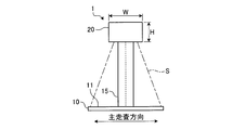
- FIG. 1 is a perspective view of an image reading apparatus according to an embodiment.
- FIG. 2 is an AA arrow view of FIG.
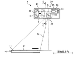
- FIG. 3 is a schematic diagram showing the configuration of the image reading apparatus shown in FIG.
- FIG. 4 is a detailed view of part C of FIG.
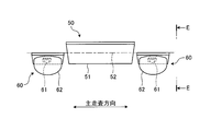
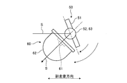
- FIG. 5 is a DD arrow view of FIG. 6 is a view taken along the line EE in FIG.
- FIG. 7 is a detailed view of the reading unit shown in FIG. 3, and is an explanatory diagram of the arrangement configuration of the reading unit.
- FIG. 8 is a schematic diagram showing the relationship between the arrangement configuration of the reading units and the optical path length.
- FIG. 9 is a BB arrow view of FIG.
- FIG. 10 is a block diagram illustrating a main configuration of the image reading apparatus according to the embodiment.
- FIG. 10 is a block diagram illustrating a main configuration of the image reading apparatus according to the embodiment.
- FIG. 11 is an explanatory diagram showing a state at the start of reading.
- FIG. 12 is an explanatory diagram showing a state at the end of reading.
- FIG. 13 is an explanatory diagram of the operation amount during the reading operation.
- FIG. 14 is an explanatory diagram showing an example of the rotational angular velocity of the sensor optical axis during scanning.
- FIG. 15 is an explanatory diagram illustrating an example of the moving speed of the second optical unit during scanning.
- FIG. 16 is an explanatory diagram of the resolution when the total optical path length is not constant.
- FIG. 17 is an explanatory diagram of the resolution when the total optical path length is constant.
- FIG. 18 is an explanatory diagram of a reading state on the placement surface.
- FIG. 16 is an explanatory diagram of the resolution when the total optical path length is not constant.
- FIG. 17 is an explanatory diagram of the resolution when the total optical path length is constant.
- FIG. 18 is an explanatory diagram of a reading state on the placement surface
- FIG. 19 is an explanatory diagram of the angle between the light emitted from the illumination unit and the sensor optical axis.
- FIG. 20 is an explanatory diagram when the moving direction of the second optical unit is vertical.
- FIG. 21 is a modified example of the image reading apparatus according to the embodiment, and is an explanatory diagram illustrating a state in which the first optical unit and the third optical unit overlap in the vertical direction.
- FIG. 22 is a modified example of the image reading apparatus according to the embodiment, and is an explanatory diagram illustrating a state in which the first optical unit is positioned between the second optical unit and the third optical unit in the sub-scanning direction.
- FIG. 23 is a modified example of the image reading apparatus according to the embodiment, and is an explanatory diagram in the case where a cylindrical mirror is used for the second optical unit.
- FIG. 24 is a modified example of the image reading apparatus according to the embodiment, and is an explanatory diagram when a prism is used for the second optical unit.
- FIG. 25 is a modified example of the image reading apparatus according to the embodiment, and is an explanatory diagram when a plurality of reading units are provided.
- FIG. 1 is a perspective view of an image reading apparatus according to an embodiment.
- FIG. 2 is an AA arrow view of FIG.
- the image reading apparatus 1 shown in FIGS. 1 and 2 is an apparatus that reads the medium P by imaging the medium P from above.
- the image reading apparatus 1 includes a mounting table 10 on which a medium P is placed and a reading unit 20 that reads the medium P.
- the mounting table 10 is formed in a rectangular plate shape, and a mounting surface 11 on which the medium P is mounted is provided on the upper surface side.
- the reading unit 20 is disposed on the upper side of the mounting table 10, that is, on the upper side of the mounting surface 11, and is connected by an arm 15 that extends substantially in the vertical direction.
- the lower end side of the arm 15 is connected to the mounting table 10 and the upper end side is connected to the reading unit 20, so that the mounting table 10 and the reading unit 20 protrude in the same direction side with respect to the arm 15 in the horizontal direction.
- the arm 15 is connected to the mounting table 10 and the reading unit 20.
- the mounting table 10 and the reading unit 20 are arranged to face each other in the vertical direction by connecting the arm 15 in this way.
- the reading unit 20 disposed to face the mounting table 10 is provided with an illumination unit 60 that can emit light toward the mounting surface 11 when the reading unit 20 reads the medium P.
- the illumination unit 60 is provided at two locations of the reading unit 20. When the reading unit 20 is viewed in the vertical direction, the two illumination units 60 are located at positions other than the portion where the arm 15 is connected in the reading unit 20 and at positions opposite to each other in the horizontal direction. Projecting in opposite directions to each other.
- FIG. 3 is a schematic diagram showing the configuration of the image reading apparatus shown in FIG.
- the reading unit 20 includes a first optical unit 30 that reads the medium P, a second optical unit 40 that turns back the optical axis when the first optical unit 30 performs reading, and light that is turned back by the second optical unit 40.
- a third optical unit 50 that reflects the axis toward the mounting surface 11 of the mounting table 10.
- the first optical unit 30, the second optical unit 40, and the third optical unit 50 are all installed in the housing 21 of the reading unit 20.
- the first optical unit 30 includes a line sensor 31 and a condenser lens 35 and is fixed to the housing 21, and the line sensor 31 places the medium P placed on the placement surface 11.
- the surface 11 can be read in a line shape in the main scanning direction.
- the main scanning direction in this case refers to the direction in which the imaging elements are arranged in the line sensor 31 formed by arranging a plurality of imaging elements that capture an image. That is, the line sensor 31 can read the imaging target in a line shape by arranging a plurality of imaging elements in a linear shape. That is, the line sensor 31 having a plurality of image sensors can generate image data by converting light received by the image sensors into electronic data by photoelectric conversion.
- the condensing lens 35 is disposed on the sensor optical axis S that is an optical axis when the line sensor 31 performs imaging, and the light that travels along the sensor optical axis S toward the line sensor 31 is transmitted to the line sensor 31. It is possible to form an image on 31 image sensors.
- the line sensor 31 receives the imaged light, and outputs an electric signal corresponding to the received light, thereby generating line-shaped image data in the main scanning direction. Note that the number of lines of the image sensor included in the line sensor 31 may be single or plural.
- the sensor optical axis S when the line sensor 31 performs imaging is an optical axis that spreads in a plane in the main scanning direction. Yes.
- the second optical unit 40 can turn back the sensor optical axis S by 180 ° when the line sensor 31 of the first optical unit 30 performs reading.
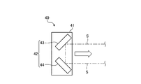
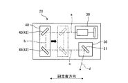
- FIG. 4 is a detailed view of part C of FIG.
- the second optical unit 40 includes a pair of folding mirrors 42 and a carrier 41 that holds the folding mirrors 42.
- the folding mirror 42 is located on the sensor optical axis S from the first optical unit 30, and the first optical unit side mirror 43 reflecting the sensor optical axis S and the sensor light reflected by the first optical unit side mirror 43.
- a third optical unit side mirror 44 which is located on the axis S and reflects the sensor optical axis S toward the third optical unit 50.
- the first optical unit side mirror 43 is installed such that the reflection surface is inclined at an angle of 45 ° with respect to the sensor optical axis S, and thus the first optical unit side mirror 43 is configured to be the first optical unit.
- the sensor optical axis S from the unit 30 can be reflected by changing the direction of 90 °.
- the first optical unit side mirror 43 can reflect the sensor optical axis S from the first optical unit 30 by changing the direction of 90 ° downward.
- the third optical unit side mirror 44 is disposed below the first optical unit side mirror 43, and reflects the sensor optical axis S reflected downward by the first optical unit side mirror 43.
- the surface is installed so as to be inclined at an angle of 45 °. Accordingly, the third optical unit side mirror 44 can reflect the sensor optical axis S reflected by the first optical unit side mirror 43 by changing the direction by 90 °.
- the third optical unit side mirror 44 can reflect the sensor optical axis S reflected by the first optical unit side mirror 43 to the side where the first optical unit 30 is located. .
- the second optical unit 40 having the folding mirror 42 composed of the first optical unit side mirror 43 and the third optical unit side mirror 44 can fold the sensor optical axis S from the first optical unit 30 by 180 °. It is possible.
- the second optical unit 40 configured as described above is provided in the housing 21 so as to be movable in the optical axis direction between the first optical unit 30 and the second optical unit 40. That is, the moving direction of the second optical unit 40 is a direction facing the mounting surface 11 of the mounting table 10 when viewed from the main scanning direction, in other words, the moving direction of the second optical unit 40. Is in a direction parallel to the mounting surface 11.
- FIG. 5 is a DD arrow view of FIG. 6 is a view taken along the line EE in FIG.
- the third optical unit 50 rotates the sensor optical axis S folded by the second optical unit 40, so that the sensor optical axis S is orthogonal to the main scanning direction on the mounting surface 11 with respect to the mounting surface 11. It can be moved in the sub-scanning direction.
- the third optical unit 50 is positioned in the sub-scanning direction between the first optical unit 30 and the second optical unit 40 in the same direction.
- the third optical unit 50 has a rotating mirror 51 that reflects the sensor optical axis S folded back by the second optical unit 40.
- the rotating mirror 51 is disposed on the sensor optical axis S folded back by the second optical unit 40, and the reflecting surface is disposed on the second optical unit 40 side and in a direction facing the lower side. ing. Accordingly, the rotating mirror 51 can reflect the sensor optical axis S folded back by the second optical unit 40 downward.
- the rotating mirror 51 is rotatable about a rotating shaft 52 extending in the main scanning direction, and the rotating shaft 52 is provided on the reflecting surface of the rotating mirror 51.
- the rotating shaft 52 is provided on the reflecting surface of the rotating mirror 51 so as to be positioned near the position where the sensor optical axis S folded by the second optical unit 40 is reflected.
- the third optical unit 50 can move the reflection direction of the sensor optical axis S reflected by the rotary mirror 51 in the sub-scanning direction by rotating the rotary mirror 51 about the rotary shaft 52.
- the rotating mirror 51 is installed in a direction capable of reflecting the sensor optical axis S on the side where the second optical unit 40 is positioned in the sub-scanning direction from the position below the rotating mirror 51 in the vertical direction.
- the third optical unit 50 moves the sensor optical axis S in the sub-scanning direction within a range not including the position where the angle of the sensor optical axis S with respect to the placement surface 11 when viewed from the main scanning direction is 90 °. It can be moved.
- An opening 25 through which the sensor optical axis S between the third optical unit 50 and the placement surface 11 passes is formed in the housing 21 of the reading unit 20.
- the opening 25 is formed in the vicinity of the third optical unit 50 on the lower surface side of the housing 21 and faces the mounting surface 11.
- the opening 25 rotates even when the sensor optical axis S reflected by the rotating mirror 51 is positioned in any part of the moving range when the rotating mirror 51 moves in the sub-scanning direction.
- the sensor optical axis S between the mirror 51 and the mounting surface 11 can be passed.
- the third optical unit 50 provided in the reading unit 20 can reflect the sensor optical axis S folded back by the second optical unit 40 toward the placement surface 11 by passing through the opening 25. it can.
- Illumination units 60 provided at two locations of the reading unit 20 are respectively disposed near both ends of the third optical unit 50 in the main scanning direction.
- Each of these illumination units 60 includes a light emitting unit 61 such as an LED (Light Emitting Diode), and a lens 62 that can irradiate light emitted from the light emitting unit 61 in a line shape.
- the illumination unit 60 can irradiate the medium P with line-shaped light.
- the illuminating unit 60 is directed to the mounting surface 11 along the sensor optical axis S that reflects light that is linear in the main scanning direction from the third optical unit 50 toward the mounting surface 11. Irradiation is possible.
- the illumination unit 60 can rotate around the rotation axis 63 of the illumination unit 60, and the rotation axis 63 is oriented to extend in the main scanning direction. For this reason, the illuminating unit 60 moves around the rotation axis 63 to move the linear light emitted from the illuminating unit 60 in the sub-scanning direction of the mounting surface 11 with respect to the mounting surface 11. It is possible.
- the rotation shaft 63 is coaxial with the rotation shaft 52 of the third optical unit 50. That is, the rotation shaft 63 of the illumination unit 60 is located on an extension line of the rotation shaft 52 of the third optical unit 50 extending in the main scanning direction. For this reason, the illumination unit 60 can rotate around the rotation axis 63 that is coaxial with the rotation axis 52 of the rotation mirror 51 of the third optical unit 50.
- the illumination unit 60 can rotate at a rotational speed twice that of the rotary mirror 51. Thereby, even when the sensor optical axis S reflected by the rotating mirror 51 moves in the sub-scanning direction in accordance with the rotation of the rotating mirror 51, the illuminating unit 60 rotates around the rotating shaft 63 to form a line shape. Light can be moved along the sensor optical axis S along with the sensor optical axis S in the sub-scanning direction.
- FIG. 7 is a detailed diagram of the reading unit shown in FIG. 3, and is an explanatory diagram of the arrangement configuration of the reading unit.
- FIG. 8 is a schematic diagram showing the relationship between the arrangement configuration of the reading units and the optical path length.
- FIG. 9 is a BB arrow view of FIG.
- the reading unit 20 includes an optical path length a of the sensor optical axis S between the first optical unit 30 and the second optical unit 40, an optical path length b between the folding mirrors 42 of the second optical unit 40, and a second optical unit.
- Each unit is arranged in a positional relationship in which the ratio of the optical path length obtained by adding the optical path length c between 40 and the third optical unit 50 to the total optical path length L, which is the entire optical path length, is small.
- the optical path length a and the optical path with respect to the total optical path length L which is the optical path length obtained by adding the optical path length d between the third optical unit 50 and the mounting surface 11 to the optical path length a, the optical path length b, and the optical path length c.
- the first optical unit 30, the second optical unit 40, and the third optical unit 50 are configured in a positional relationship in which the ratio of the length b to the optical path length c is reduced.
- the sensor optical axis S spreads in the main scanning direction as the distance from the line sensor 31 increases, so that the optical path length a between the first optical unit 30 and the second optical unit 40 increases at the position of the second optical unit 40.
- the width of the sensor optical axis S in the main scanning direction increases.
- the width of the sensor optical axis S in the main scanning direction at the position of the third optical unit side mirror 44 increases. For these reasons, as the optical path length a between the first optical unit 30 and the second optical unit 40 becomes longer or the optical path length b between the folding mirrors 42 becomes longer, the second optical unit 40 in the main scanning direction becomes longer. It is necessary to increase the width e.
- the width in the main scanning direction of the sensor optical axis S at the position of the third optical unit 50 increases.
- the width f of the third optical unit 50 in the main scanning direction needs to be increased.
- the width e of the second optical unit 40 and the width f of the third optical unit 50 in the main scanning direction can be reduced, and the width W of the reading unit 20 can be reduced.
- the first optical unit 30, the second optical unit 40, and the third optical unit 50 are arranged in a positional relationship that allows the optical path length a, the optical path length b, and the optical path length c to be relatively short.
- the first optical unit 30, the second optical unit 40, and the third optical unit 50 are arranged in a positional relationship in which the ratio of the optical path length a, the optical path length b, and the optical path length c to the total optical path length L is small. Yes.
- FIG. 10 is a block diagram illustrating a main configuration of the image reading apparatus according to the embodiment.
- the reading unit 20 is provided with a U-turn motor 45 and a rotation motor 55.
- the U-turn motor 45 is a first actuator that moves the second optical unit 40 relative to the first optical unit 30 in the optical axis direction between the first optical unit 30 and the second optical unit 40. It is provided as. That is, the U-turn motor 45 moves the second optical unit 40 close to or away from the first optical unit 30 by moving the second optical unit 40 along the optical axis direction between the first optical unit 30 and the second optical unit 40. It is possible to do.
- the rotation motor 55 is provided as a second actuator that rotates the third optical unit 50 around a rotation axis 52 parallel to the main scanning direction. That is, the rotation motor 55 rotates the rotation mirror 51 around the rotation axis 52. It can be rotated.
- the rotation motor 55 can rotate the illumination unit 60 about the rotation shaft 63.
- the rotation motor 55 can transmit the power generated by the rotation motor 55 to the rotary mirror 51 and the illumination unit 60 via the speed ratio transmission mechanism.
- the speed ratio when the generated power is transmitted to the rotating mirror 51 and the illumination unit 60 can be transmitted at a speed ratio of 1: 2. That is, among the rotary mirror 51 and the illumination unit 60 that are both rotated by the power transmitted from the rotary motor 55, the illumination unit 60 rotates with a change amount that is twice the change amount of the rotation angle of the rotary mirror 51. do.
- the image reading apparatus 1 also includes a control circuit 70.
- the control circuit 70 is a CPU (Central Processing Unit) that functions as a controller that executes various processes, and a RAM (Random) that functions as a memory that stores various information.
- the computer has an Access Memory (ROM) and a ROM (Read Only Memory). All or part of each function of the control circuit 70 is realized by reading and writing data in the RAM or ROM by loading an application program held in the ROM into the RAM and executing it by the CPU. .
- the control circuit 70 controls the line sensor 31 included in the first optical unit 30 to read an image, a motor control unit 72 that controls the U-turn motor 45 and the rotation motor 55, and an illumination unit 60. And an illumination control unit 73 that controls turning on and off.
- the control circuit 70 includes an image processing unit 74 that performs image processing of an image read by the image reading control unit 71 and a storage unit 75 that stores various types of information such as read image information.
- the control circuit 70 includes a communication unit 76 that communicates with an external device.
- the communication unit 76 is connected to an external device by wire or wireless, and can transmit and receive information.
- a PC (Personal Computer) 80 is used, and the communication unit 76 can communicate with the PC 80.
- the image reading apparatus 1 is provided with a scan switch 78 that causes the image reading apparatus 1 to perform a reading operation.
- the scan switch 78 is disposed on the top surface of the mounting table 10, and when an input operation is performed by the user, the scan switch 78 transmits the fact to the control circuit 70, thereby reading the image reading apparatus 1. It is possible to make an action take place.
- FIG. 11 is an explanatory diagram showing a state at the start of reading.
- the control circuit 70 controls the reading unit 20 when the user performs an input operation on the scan switch 78 with the medium P placed on the placement surface 11 of the placement table 10.
- the reading unit 20 is caused to read the medium P.
- the control circuit 70 controls the U-turn motor 45 and the rotation motor 55 by the motor control unit 72, thereby causing the second optical unit 40 and the third optical unit 50 to move.
- the image reading control unit 71 obtains an image read by the line sensor 31 included in the first optical unit 30 in a reading start state.
- control circuit 70 moves the second optical unit 40 to a position farthest from the first optical unit 30 in the moving direction of the second optical unit 40.
- control circuit 70 reflects the sensor optical axis S turned back by the second optical unit 40 by the rotary mirror 51 and moves the vertical position of the rotary mirror 51 in the movement range when moving the sensor optical axis S on the mounting surface 11 in the sub-scanning direction.
- the rotary mirror 51 is rotated at a rotation angle that directs the sensor optical axis S to a position closest to the lower side in the direction.
- the image reading apparatus 1 is reflected at the position closest to the lower side in the vertical direction of the rotating mirror 51 in the moving direction of the sensor optical axis S moving in the sub-scanning direction on the mounting surface 11, that is, reflected by the rotating mirror 51.
- the position closest to the arm 15 in the moving direction of the sensor optical axis S that moves in the sub-scanning direction on the mounting surface 11 is the position of the sensor optical axis S at the start of reading.
- the illumination control unit 73 controls the illumination unit 60 to turn on the illumination unit 60, thereby irradiating the mounting surface 11 with linear light that spreads in the main scanning direction.
- the power of the rotary motor 55 is transmitted to the illumination unit 60 via the speed ratio transmission mechanism, and the illumination unit 60 is rotated on the placement surface 11 by the rotation of the illumination unit 60 by the rotation motor 55. Irradiate the position where S is located. That is, when viewed in the main scanning direction, the illumination unit 60 irradiates the mounting surface 11 with the irradiation light so as to overlap the sensor optical axis S that is reflected by the rotary mirror 51 and travels toward the mounting surface 11.
- the irradiation light irradiated from the illumination unit 60 is linear light spreading in the main scanning direction
- the irradiation light irradiated to the mounting surface 11 is linear in the main scanning direction on the mounting surface 11. It is irradiated in a state where it overlaps the sensor optical axis S that spreads out. That is, the illuminating unit 60 irradiates light onto a region that is read in a line shape in the main scanning direction on the placement surface 11 by the line sensor 31.
- the control circuit 70 acquires an image read by the line sensor 31 by the image reading control unit 71, thereby acquiring line-shaped image information extending in the main scanning direction on the placement surface 11. That is, the medium P on the placement surface 11 irradiated with the light from the illumination unit 60 reflects this light, and a part of the reflected light enters the rotating mirror 51 along the sensor optical axis S.
- the rotating mirror 51 reflects this light along the sensor optical axis S toward the second optical unit 40, and the second optical unit 40 returns this light along the sensor optical axis S by the folding mirror 42. It is directed to the first optical unit 30.
- the first optical unit 30 transmits light traveling from the second optical unit 40 along the sensor optical axis S toward the first optical unit 30 through the condenser lens 35 and then received by the line sensor 31.
- the line sensor 31 converts the received light into an electrical signal, and transmits the converted electrical signal to the image reading control unit 71, whereby the image reading control unit 71 acquires the image information.
- the image reading control unit 71 acquires line-shaped image information extending in the main scanning direction on the placement surface 11.
- the control circuit 70 controls the U-turn motor 45 and the rotary motor 55 by the motor control unit 72 while acquiring the line-shaped image information by the image reading control unit 71.
- the sensor optical axis S reflected by the rotating mirror 51 of the third optical unit 50 toward the mounting surface 11 is moved in the sub-scanning direction while the second optical unit 40 is moved in the direction approaching the first optical unit 30.
- the rotating mirror 51 is rotated in the direction of moving away from the arm 15.
- the illumination unit 60 rotates at a rotational speed twice that of the rotary mirror 51, so that the irradiation direction of the illumination unit 60 along with the sensor optical axis S moving in the sub-scanning direction on the mounting surface 11 is the arm 15. Is moved in the sub-scanning direction, and the line-shaped light is irradiated to the position where the sensor optical axis S is located on the placement surface 11. Accordingly, the line sensor 31 reads the medium P on the placement surface 11 while moving on the placement surface 11 in the sub-scanning direction.
- FIG. 12 is an explanatory diagram showing a state at the end of reading.
- the reading unit 20 moves the sensor optical axis S in the sub-scanning direction on the placement surface 11 as described above while reading with the line sensor 31, and the arm 15 is located in the movement range of the sensor optical axis S.
- the reading operation is finished when the end of the side is moved to the opposite end. That is, the control circuit 70 controls the U-turn motor 45 and the rotary motor 55 by the motor control unit 72, thereby moving the second optical unit 40 to the position at the start of reading and the third optical unit 50.
- the rotating mirror 51 and the illumination unit 60 are rotated to the rotation position at the start of reading.
- the second optical unit 40 is moved in the direction in which the second optical unit 40 is separated from the first optical unit 30 along the sensor optical axis S between the first optical unit 30 and the second optical unit 40.
- the rotating mirror 51 rotates the sensor optical axis S on the placement surface 11 in the sub-scanning direction in a direction approaching the arm 15, and the illumination unit 60 similarly irradiates the placement surface 11 in the sub-scanning direction.
- the light irradiation position is rotated in a direction approaching the arm 15.
- the image reading control unit 71 reads the image while moving the sensor optical axis S on the mounting surface 11 in the sub-scanning direction as described above, thereby converting the line-shaped image information extending in the main scanning direction into the sub-scanning direction. Are combined and read as a two-dimensional image in the main scanning direction and the sub-scanning direction.
- the image read as described above is subjected to image processing such as cropping by the image processing unit 74 so as to be an appropriate image as the image on the medium P, and stored in the storage unit 75.
- the image stored in the storage unit 75 is transmitted to the PC 80 via the communication unit 76 as necessary, and is stored in the PC 80 or performs arbitrary information processing.
- FIG. 13 is an explanatory diagram of the operation amount during the reading operation.
- the time is t
- the position of the sensor optical axis S on the placement surface 11 in the sub-scanning direction is y (t)
- the sensor optical axis S at the start of reading can be expressed by the following equation (1).
- y (0) y 0 (1)
- the rotation speed of the rotating mirror 51 is rotated so that the moving speed of the sensor optical axis S in the sub-scanning direction during the reading operation is constant on the placement surface 11.
- y (t) vt + y 0 (3)
- the rotating mirror 51 when the rotating mirror 51 is rotated, the incident angle of the sensor optical axis S incident on the rotating mirror 51 from the second optical unit 40 and the sensor optical axis S reflected by the rotating mirror 51 toward the mounting surface 11 Both the emission angle changes. For this reason, when the sensor optical axis S reflected by the rotating mirror 51 and directed to the placement surface 11 is to be rotated by an arbitrary ⁇ , the rotating mirror 51 is rotated by ⁇ / 2. As a result, the sensor optical axis S incident on the rotary mirror 51 from the second optical unit 40 and reflected by the rotary mirror 51 toward the mounting surface 11 rotates by ⁇ .
- the optical path length d between the third optical unit 50 and the placement surface 11 changes.
- the amount of change in the optical path length d is calculated based on the optical path length a of the sensor optical axis S between the first optical unit 30 and the second optical unit 40, and the second.
- the second optical unit 40 is moved in a direction in which the optical path length a and the optical path length c can be changed. That is, the second optical unit 40 is moved in the sub scanning direction.
- the relationship between the total optical path length L and the optical path length a, the optical path length b, the optical path length c, and the optical path length d can be represented by the following formula (4).
- the optical path length a and the optical path length c are decreased by ⁇ d / 2, respectively. That is, when the optical path length d increases by ⁇ d, the optical path length a and the optical path length are moved by moving the second optical unit 40 toward the first optical unit 30 or the third optical unit 50 by ⁇ d / 2. c is decreased by ⁇ d / 2.
- the moving amount x of the second optical unit 40 is 1 ⁇ 2 of the increment of the optical path length d changed by the rotation of the sensor optical axis S.
- the moving speed u (t) of the second optical unit 40 is expressed by the following formula (8).
- u (t) (2v 2 t + 2 vy 0 ) / (h 2 + v 2 t 2 +2 vty 0 + y 0 2 ) 0.5 / 4 (8)
- FIG. 14 is an explanatory diagram showing an example of the rotational angular velocity of the sensor optical axis during scanning.
- FIG. 15 is an explanatory diagram illustrating an example of the moving speed of the second optical unit during scanning. Since the rotational angular velocity ⁇ (t) of the sensor optical axis S when reading the medium P can be expressed by the above equation (6), the rotational angular velocity ⁇ (t) of the sensor optical axis S is shown in FIG. As shown in FIG. 4, the speed decreases as the scanning time t in scanning the mounting surface 11 elapses. Thereby, the sensor optical axis S can be moved on the mounting surface 11 at a constant speed in the sub-scanning direction, and the mounting surface 11 can be scanned at a constant speed in the sub-scanning direction.
- the moving speed u (t) of the second optical unit 40 can be expressed as in (8) above, the moving speed u (t) of the second optical unit 40 is as shown in FIG.
- the scanning time t in scanning the mounting surface 11 elapses, the speed increases. That is, the optical path length d between the third optical unit 50 and the placement surface 11 increases as the rotation angle ⁇ of the sensor optical axis S increases, with respect to the change amount of the rotation angle ⁇ . . Therefore, in order to compensate for the amount of change in the optical path length d that increases as the rotation angle ⁇ of the sensor optical axis S increases, the rotation angle ⁇ of the sensor optical axis S increases as the scanning time t elapses. The moving speed u (t) of the second optical unit 40 is increased. As a result, the total optical path length L can be made constant regardless of the position of the sensor optical axis S in the sub-scanning direction on the placement surface 11.
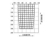
- FIG. 16 is an explanatory diagram of the resolution when the total optical path length is not constant.
- FIG. 17 is an explanatory diagram of the resolution when the total optical path length is constant.
- the optical path length d between the rotating mirror 51 and the placement surface 11 reads a position far from the lower part in the vertical direction of the rotating mirror 51 than the optical path length in the case of reading the lower part in the vertical direction of the rotating mirror 51. In this case, the optical path length is longer.
- the sensor optical axis S spreads in the main scanning direction as the distance from the line sensor 31 increases. Therefore, in the read image, an image in a wider range is read in the main scanning direction as the distance from the line sensor 31 increases. For this reason, an image of a reading object having an arbitrary width in the main scanning direction is read as a part of a wide reading range as the distance from the line sensor 31 increases, so that the width in the main scanning direction is reduced. Therefore, as shown in FIG. 16, the image read by the line sensor 31 has a width in the main scanning direction as the sensor optical axis S is inclined and the scanning position moves away from the vertical lower side of the rotary mirror 51 in the sub-scanning direction. Is reduced and read.
- the image reading apparatus 1 when the medium P is read by rotating the sensor optical axis S, the total optical path length L is constant, so that the rotation angle of the sensor optical axis S is related.
- the reading range g (see FIG. 8) in the main scanning direction can be made constant.
- the image read by the line sensor 31 is independent of the scanning position in the sub-scanning direction even when the scanning position is moved in the sub-scanning direction by rotating the sensor optical axis S.
- the reading width g in the main scanning direction can be read with a constant value.
- the control circuit 70 adjusts the third optical unit so that the total optical path length L of the sensor optical axis S is a constant distance.
- the amount of movement of the second optical unit 40 is controlled in conjunction with the amount of rotation of 50. As a result, reading is performed with the reading range g in the main scanning direction constant, regardless of the scanning position in the sub-scanning direction.
- the rotation range of the sensor optical axis S is the angle ⁇ of the sensor optical axis S with respect to the angle below the vertical direction of the rotary mirror 51. If the angle exceeds 45 °, the amount of change in the optical path length d between the third optical unit 50 and the placement surface 11 increases. In this case, since the amount of movement of the second optical unit 40 increases to compensate for the amount of change in the optical path length d, the entire reading unit 20 becomes large.
- the angle ⁇ of the sensor optical axis S becomes too large, the reading range g in the main scanning direction becomes too wide, so that the width of the image of the reading object such as the medium P in the main scanning direction becomes relatively small. Since the sensor optical axis S is directed from an oblique direction that is greatly inclined with respect to the mounting surface 11, the resolution is lowered. For this reason, when reading an image, it is preferable to read the sensor optical axis S while rotating the sensor optical axis S in a range where the angle ⁇ of the sensor optical axis S is less than 45 °.
- the angle ⁇ of the sensor optical axis S tends to increase as the maximum angle ⁇ at the time of reading increases as the height from the mounting surface 11 to the rotating mirror 51 decreases.
- the height from the mounting surface 11 to the rotating mirror 51 is set so that the angle ⁇ of the sensor optical axis S at the time of image reading is less than 45 °.
- FIG. 18 is an explanatory diagram of a reading state on the placement surface.
- the reading range in the sub-scanning direction changes according to the angle of the sensor optical axis S with respect to the mounting surface 11. That is, the reading range of one pixel of the line sensor 31 on the placement surface 11, and the sub-scanning direction in the case of reading in a line in the main scanning direction by the line sensor 31 on the placement surface 11 by the sensor optical axis S.
- the one-pixel reading range 90 which is the reading range
- the length q in the sub-scanning direction changes according to the angle of the sensor optical axis S with respect to the placement surface 11.
- the length q of the one-pixel reading range 90 in the sub-scanning direction becomes shorter as the rotation angle ⁇ of the sensor optical axis S becomes smaller and the sensor optical axis S becomes nearly vertical, and the rotation angle ⁇ of the sensor optical axis S becomes smaller. Increases and becomes longer as the sensor optical axis S tilts. Therefore, the one-pixel reading range 90 includes a wide range of the image 91 in the sub-scanning direction as the rotation angle ⁇ of the sensor optical axis S increases, and various image shapes are included in the one-pixel reading range 90. May be included.
- the line sensor 31 converts the total light amount incident on each pixel into an electric signal 92 and outputs the electric signal 92, and reads the image as one image by combining the electric signal 92 converted by each pixel. For this reason, when the one-pixel reading range 90 includes a wide range of the image 91, the electric signal 92 suitable for an image that may include various shapes is included in one pixel of the line sensor 31. It becomes difficult to generate.
- the pitch p when the sensor optical axis S moves in the sub-scanning direction is a pitch according to the resolution of the image to be captured, and is constant regardless of the rotation angle ⁇ of the sensor optical axis S. For this reason, when the sensor optical axis S is rotated to move the reading position in the sub-scanning direction, the one-pixel reading range 90 is moved within a range that is 1.4 times the moving pitch p of the sensor optical axis S. Is preferred.
- the third optical unit 50 has a length q in the sub-scanning direction of the one-pixel reading range 90 equal to 1. of the movement pitch p when moving the sensor optical axis S in the sub-scanning direction. It is preferable to move the sensor optical axis S in the sub-scanning direction by rotating the rotary mirror 51 within a range of 4 times or less.
- the line sensor 31 reads the image of the medium P by detecting light when the irradiation light from the illumination unit 60 is reflected by the medium P. However, the irradiation light from the illumination unit 60 is regularly reflected by the medium P. However, when the specularly reflected light is incident on the line sensor 31, an area where reading cannot be performed by the specularly reflected light may occur. For this reason, in the image reading apparatus 1 according to the present embodiment, the sensor optical axis S is moved in the sub-scanning direction within a range in which an area that cannot be read by regular reflection light does not occur when reading an image.
- FIG. 19 is an explanatory diagram of the angle of the light irradiated from the illumination unit and the sensor optical axis.
- the angle at which the light 100 reflected as a specularly reflected light to the line sensor 31 when reflected by the medium P is directed to the placement surface 11 is such that the sensor optical axis S at a predetermined rotation angle ⁇ intersects the placement surface 11.
- the angle is 2 ⁇ with respect to the sensor optical axis S.
- the illuminating unit 60 of the image reading apparatus 1 rotates around the rotation axis 63 coaxial with the rotation axis 52 of the rotary mirror 51 of the third optical unit 50 and irradiates along the sensor optical axis S. Irradiate light. For this reason, when the irradiation light from the illumination unit 60 is regularly reflected by the medium P, this light is reflected along the sensor optical axis S when the rotation angle ⁇ of the sensor optical axis S is 0 °. End up.
- the image reading apparatus 1 when the irradiation light from the illumination unit 60 is regularly reflected by the medium P, the light is not reflected along the sensor optical axis S from the main scanning direction.
- the sensor optical axis S is moved in the sub-scanning direction within a range not including a position where the angle of the sensor optical axis S with respect to the placement surface 11 when viewed is 90 °. That is, when reading the image by moving the sensor optical axis S from the position close to the arm 15 in the sub-scanning direction to the direction away from the arm 15 in the sub-scanning direction, the sensor light at the reading start position is read.
- the rotation angle ⁇ 0 of the axis S should not be 0 °.
- the rotation angle ⁇ 0 of the sensor optical axis S at the reading start position is preferably ⁇ 0 > 10 ° by including the margin in consideration of the shape of the illumination unit 60 and the unevenness of the medium P.
- the image reading apparatus 1 When reading an image, the image reading apparatus 1 according to the above embodiment is configured so that the total optical path length L of the sensor optical axis S is a constant distance when the sensor optical axis S is moved in the sub-scanning direction. Since the movement amount of the second optical unit 40 is controlled in conjunction with the rotation amount of the optical unit 50, an image is read with a constant resolution regardless of the position of the sensor optical axis S in the sub-scanning direction on the mounting surface 11. be able to. Thereby, a high quality image can be easily obtained. Further, since the moving direction of the second optical unit 40 is the direction facing the placement surface 11 when viewed from the main scanning direction, that is, the direction parallel to the placement surface 11, the reading unit 20 is small. Can be achieved.
- FIG. 20 is an explanatory diagram when the moving direction of the second optical unit is vertical.
- the second optical unit 40 is positioned below the rotating mirror 51 of the third optical unit 50, and thus the sensor optical axis reflected by the rotating mirror 51.
- S scans by reflecting the sensor optical axis S toward a position far away from the lower part of the rotating mirror 51 in the vertical direction.
- the rotating mirror 51 needs to be arranged at a high position.
- the moving direction of the second optical unit 40 is the direction facing the placement surface 11 when viewed from the main scanning direction
- the image is viewed from a position near the lower side in the vertical direction of the rotating mirror 51.
- the illumination unit irradiates the mounting surface 11 with linear light, and moves the irradiation light in the sub-scanning direction on the mounting surface 11 with the rotation shaft 63 being coaxial with the rotation shaft 52 of the rotating mirror 51.
- the reading position of the line sensor 31 can be illuminated by the illumination unit 60 regardless of the angle of the sensor optical axis S reflected by the rotating mirror 51. Thereby, a high quality image can be obtained.
- the illumination unit 60 rotates coaxially with the rotation axis 52 of the rotary mirror 51, the position where the sensor optical axis S intersects the medium P is illuminated regardless of the thickness of the medium P to be read. It can be illuminated with part 60. As a result, a high-quality image can be obtained regardless of the thickness of the medium P.
- the third optical unit 50 moves the sensor optical axis S in the sub-scanning direction within a range not including the position where the angle of the sensor optical axis S with respect to the placement surface 11 when viewed from the main scanning direction is 90 °. Therefore, it is possible to suppress the occurrence of an area that cannot be read due to the specularly reflected light reflected by the medium P when the image is read. As a result, a high-quality image can be obtained more reliably regardless of the material of the medium P.
- the reading unit 20 can be more reliably downsized. That is, as shown in FIG. 20, when the second optical unit 40 is disposed below the rotating mirror 51 by making the moving direction of the second optical unit 40 vertical, the second optical unit 40 is reflected by the rotating mirror 51.
- the opening 25 through which the sensor optical axis S passes is formed on the side surface of the housing 21 in a direction opening in the horizontal direction. In this case, since the hole through which the sensor optical axis S that scans in the horizontal direction passes is formed in the side surface of the housing 21, the opening 25 is formed with a large width in the vertical direction. Become.
- the opening 25 is formed on the side surface of the housing 21, the opening 25 is formed at a position away from the rotary mirror 51, so that the width in the main scanning direction is also large. Become. That is, the sensor optical axis S spreads in the main scanning direction as the distance from the line sensor 31 increases. Therefore, when the opening 25 is formed at a position away from the rotary mirror 51, the sensor optical axis that passes through the opening 25 is used. S passes in a wide state in the main scanning direction. Accordingly, in order to pass the sensor optical axis S having a wide width in the main scanning direction, the opening 25 needs to be wide in the main scanning direction. For this reason, when the moving direction of the second optical unit 40 is set to the vertical direction, the size of the housing 21 is increased due to the opening 25 being large, and the reading unit 20 is easily increased in size.
- the moving direction of the second optical unit 40 is set to a direction facing the placement surface 11 when viewed from the main scanning direction, and the opening 25 is oriented to face the placement surface 11.
- the opening 25 can be brought close to the rotating mirror 51.
- the size of the opening 25 can be reduced, and the size of the housing 21 can be reduced, whereby the reading unit 20 can be reduced in size.
- the length q in the sub-scanning direction of the one-pixel reading range 90 is within a range that is 1.4 times or less of the pitch p when the sensor optical axis S is moved in the sub-scanning direction. Since the axis S is moved in the sub-scanning direction, an image can be read with high resolution regardless of the rotation angle ⁇ of the sensor optical axis S. As a result, the image quality of the read image can be improved more reliably.
- the reading unit 20 is configured such that the arrangement position of the third optical unit 50 in the sub-scanning direction is the arrangement position of the first optical unit 30 and the second optical unit 40. Although it is configured to be positioned between the arrangement positions, the reading unit 20 may be configured in other arrangement forms.
- FIG. 21 is a modified example of the image reading apparatus according to the embodiment, and is an explanatory diagram illustrating a state where the first optical unit and the third optical unit overlap in the vertical direction. For example, as shown in FIG. 21, the reading unit 20 may be arranged such that the first optical unit 30 and the third optical unit 50 overlap in the vertical direction.
- the optical path length b between the folding mirrors 42 becomes long, and the vertical height H of the reading unit 20 (see FIG. 9) is.
- the length of the reading unit 20 in the sub-scanning direction can be shortened. Thereby, size reduction of the reading unit 20 can be achieved.
- FIG. 22 is a modified example of the image reading apparatus according to the embodiment, and is an explanatory diagram illustrating a state in which the first optical unit is positioned between the second optical unit and the third optical unit in the sub-scanning direction.
- the reading unit 20 may be arranged such that the first optical unit 30 is positioned between the second optical unit 40 and the third optical unit 50 in the sub-scanning direction. In this case, in the sub-scanning direction, it is possible to reduce the number of members disposed in the portion opposite to the side where the second optical unit 40 is located with respect to the third optical unit 50.
- the image reading apparatus 1 when viewed as a whole in the image reading apparatus 1, it is possible to reduce a portion that protrudes on the opposite side of the side on which the mounting surface 11 is located from the arm 15 in the sub-scanning direction. The size can be reduced when viewed.
- the arrangement of the first optical unit 30, the second optical unit 40, and the third optical unit 50 included in the reading unit 20 is such that the optical path length a + the optical path length b + the optical path length c is reduced, or reading in front of the image reading apparatus 1. It is preferable to set appropriately in consideration of the protruding state of the unit 20 and the apparent volume.
- the second optical unit 40 has a sensor optical axis S of 180 by the folding mirror 42 including the first optical unit side mirror 43 and the third optical unit side mirror 44.
- the configuration of folding back the sensor optical axis S may be realized by means other than the folding mirror 42.
- FIG. 23 is a modified example of the image reading apparatus according to the embodiment, and is an explanatory diagram in the case where a cylindrical mirror is used for the second optical unit.
- FIG. 24 is a modified example of the image reading apparatus according to the embodiment, and is an explanatory diagram when a prism is used for the second optical unit. For example, as shown in FIG.
- the second optical unit 40 uses a cylindrical mirror 110 whose inner surface is a reflecting surface of a semicircular cylindrical member, and reflects twice by the reflecting surface of the cylindrical mirror 110. Accordingly, the sensor optical axis S may be folded back 180 °.
- the second optical unit 40 may use a prism 115 and reflect the sensor optical axis S 180 ° by reflecting twice by internal reflection of the prism 115.
- the member for turning back the sensor optical axis S by 180 ° can be constituted by one member, so that the productivity is improved. Can be improved.
- the illumination units 60 are provided at two locations of the reading unit 20, but the illumination units 60 may be provided at two or more locations of the reading unit 20.
- a plurality of illumination units 60 provided in the reading unit 20 may be provided on both sides in the main scanning direction with the rotating mirror 51 of the third optical unit 50 interposed therebetween.
- FIG. 25 is a modified example of the image reading apparatus according to the embodiment, and is an explanatory diagram when a plurality of reading units are provided.
- two reading units 20 may be provided in one image reading apparatus 1.
- the two reading units 20 are arranged by being connected to one arm 15. In this way, by providing a plurality of reading units 20, a large medium P can be read by one reading unit 20, and when the medium P is a book, different pages can be read by each reading unit 20. Can do.
Landscapes
- Engineering & Computer Science (AREA)
- Multimedia (AREA)
- Signal Processing (AREA)
- Physics & Mathematics (AREA)
- General Physics & Mathematics (AREA)
- Theoretical Computer Science (AREA)
- Facsimile Scanning Arrangements (AREA)
Abstract
画像読取装置1において読み取る画像の高画質化と装置の小型化とを両立するために、載置面11に載置された媒体Pを読み取るラインセンサ31と、ラインセンサ31のセンサ光軸S上に配置される集光レンズ35とを備える第1光学ユニット30と、センサ光軸Sを180°折り返す第2光学ユニット40と、第2光学ユニット40により折り返されたセンサ光軸Sを回転することで載置面11における副走査方向に移動させる第3光学ユニット50と、第2光学ユニット40を第1光学ユニット30と第2光学ユニット40との間の光軸方向に相対移動させるUターンモータ45と、を備え、第2光学ユニット40の移動方向は主走査方向から見た場合に載置面11に対して対向しており、センサ光軸Sを副走査方向に移動する際に、センサ光軸Sの全光路長Lが一定距離となるように、第3光学ユニット50の回転量に連動して第2光学ユニット40の移動量を制御する。
Description
本開示は、画像読取装置に関する。
受光した光を電気信号に変換する撮像素子を用いて撮像を行う画像読取装置の中には、撮像素子がライン状に並んだ、いわゆるラインセンサを使用し、ラインセンサでの読み取り位置を、撮像素子が並ぶ方向と直交する方向である副走査方向に媒体上で移動させながら読み取りを行うものがある。また、このように読み取り位置を副走査方向に移動させながら読み取りを行う画像読取装置の中には、ラインセンサを回転させたり、ラインセンサで読み取りを行う際における光軸を反射するミラーを回転させたりすることにより、ラインセンサを大きく移動させることなく読み取り位置を移動させるものがある。しかし、このようにラインセンサやミラーを回転させることにより、読み取り位置を媒体上で移動させる場合、読み取り位置の移動に伴ってラインセンサと媒体との間の光路長が変化してしまい、読み取り画像に歪みが発生しまう。また、光路長が変化する場合には、被写界深度の深いレンズが必要になるが、被写界深度の深いレンズを用いると、画質が低下し易くなったり、レンズの絞りを大きくする必要があるため暗くなって画質が劣化したりし易くなる。
このため、従来の画像読取装置の中には、画像の読み取り時に、ラインセンサの光軸を反射するミラーの回転に伴って光路長を変更することができる方向にラインセンサの位置を移動させることにより、画像の読み取り時における光路長を一定にしているものがある(例えば、特許文献1)。また、従来の画像読取装置の中には、他にも光軸が垂直方向になる向きで位置が固定されるラインセンサと、回転することにより読み取り位置を副走査方向に移動させることができるミラーとを備え、さらに、ラインセンサの光軸を折り返すことにより、回転するミラーに向けて光軸を反射するミラーを有し、光軸を折り返すミラーを垂直方向に移動させることにより、画像の読み取り時における光路長を一定にしているものがある(例えば、特許文献2)。
しかしながら、光路長を一定にするためにラインセンサを移動させる場合、ラインセンサを移動させるためのスペースを大きくとる必要がある。また、画像読取装置が有するラインセンサ等の各機器は、通常、筐体に内設されているため、回転することによって読み取り位置を副走査方向に移動させるミラーは、筐体に形成される開口部から媒体を読み取ることになる。この場合、回転するミラーでラインセンサの光軸を反射することによって媒体を読み取る際に、垂直方向に向かう光軸を折り返すミラー等の機器を避けて読み取ることができるように、開口部は、筐体の側壁部分に形成されることになる。このため、開口部は、縦方向に長くなることになる。
また、回転するミラーは、筐体の側壁部分に形成される開口部の上方側の位置から媒体を読み取るため、開口部の下端側は、回転するミラーの位置から離れることになる。主走査方向の読み取り範囲は、回転するミラーから離れるに従って、主走査方向に大きくなるため、開口部の下端側は、このように主走査方向に大きくなる読み取り範囲に合わせて主走査方向に大きくする必要がある。これらのように、ラインセンサの光軸を反射し、回転することによって読み取り位置を副走査方向に移動させるミラーを用いる場合において、光路長を一定にする際には、大きなスペースが必要であったり、開口部が形成される筐体を大きくする必要があったりするため、装置が大型化してしまうことになっていた。
本開示は、上記に鑑みてなされたものであって、読み取る画像の高画質化と装置の小型化とを両立することのできる画像読取装置を提供することを目的とする。
上述した課題を解決し、目的を達成するために、本開示に係る画像読取装置は、載置面に載置された媒体を前記載置面の主走査方向においてライン状に読み取るラインセンサと、前記ラインセンサのセンサ光軸上に配置される集光レンズとを備える第1光学ユニットと、前記センサ光軸を180°折り返す第2光学ユニットと、前記第2光学ユニットにより折り返された前記センサ光軸を回転することで、前記載置面に対して、前記センサ光軸を前記載置面における前記主走査方向と直交する副走査方向に移動させる第3光学ユニットと、前記第2光学ユニットを前記第1光学ユニットに対して、前記第1光学ユニットと、前記第2光学ユニットとの間の光軸方向に相対移動させる第1アクチュエータと、前記第3光学ユニットを前記主走査方向と平行な回転軸周りに回転させる第2アクチュエータと、少なくとも前記第1アクチュエータ及び前記第2アクチュエータを制御する制御回路と、を備え、前記第2光学ユニットの移動方向は、前記主走査方向から見た場合に前記載置面に対して対向しており、前記制御回路は、前記センサ光軸を前記副走査方向に移動する際に、前記センサ光軸の全光路長が一定距離となるように、前記第3光学ユニットの回転量に連動して前記第2光学ユニットの移動量を制御する。
本開示に係る画像読取装置は、読み取る画像の高画質化と装置の小型化とを両立することができる、という効果を奏する。
以下に、本開示に係る画像読取装置の実施形態を図面に基づいて詳細に説明する。なお、この実施形態によりこの発明が限定されるものではない。また、下記実施形態における構成要素には、当業者が置換可能、且つ、容易なもの、或いは実質的に同一のものが含まれる。
〔実施形態〕
図1は、実施形態に係る画像読取装置の斜視図である。図2は、図1のA-A矢視図である。図1、図2に示す画像読取装置1は、媒体Pを上方から撮像することにより媒体Pを読み取る装置になっている。この画像読取装置1は、媒体Pを載置する載置台10と、媒体Pを読み取る読取ユニット20と、を有している。載置台10は、矩形の板状の形状で形成されており、上面側に、媒体Pを載置する載置面11が設けられている。読取ユニット20は、載置台10の上方側、即ち、載置面11の上方側に配設されており、略上下方向に延在するアーム15によって連結されている。アーム15は、下端側が載置台10に連結され、上端側が読取ユニット20に連結されており、水平方向において載置台10と読取ユニット20とがアーム15に対して同じ方向側に突出するように、アーム15は載置台10と読取ユニット20とに連結されている。載置台10と読取ユニット20とは、このようにアーム15が連結されることにより、上下方向において対向して配設されている。
図1は、実施形態に係る画像読取装置の斜視図である。図2は、図1のA-A矢視図である。図1、図2に示す画像読取装置1は、媒体Pを上方から撮像することにより媒体Pを読み取る装置になっている。この画像読取装置1は、媒体Pを載置する載置台10と、媒体Pを読み取る読取ユニット20と、を有している。載置台10は、矩形の板状の形状で形成されており、上面側に、媒体Pを載置する載置面11が設けられている。読取ユニット20は、載置台10の上方側、即ち、載置面11の上方側に配設されており、略上下方向に延在するアーム15によって連結されている。アーム15は、下端側が載置台10に連結され、上端側が読取ユニット20に連結されており、水平方向において載置台10と読取ユニット20とがアーム15に対して同じ方向側に突出するように、アーム15は載置台10と読取ユニット20とに連結されている。載置台10と読取ユニット20とは、このようにアーム15が連結されることにより、上下方向において対向して配設されている。
載置台10に対して対向して配設される読取ユニット20には、読取ユニット20での媒体Pの読み取り時に、光を載置面11に向けて照射することのできる照明部60が設けられており、照明部60は、読取ユニット20の2箇所に設けられている。2箇所の照明部60は、読取ユニット20を上下方向に見た場合に、読取ユニット20においてアーム15が連結されている部分以外の位置で、且つ、水平方向において互いに反対側となる位置に、互いに反対方向に突出して設けられている。
図3は、図1に示す画像読取装置の構成を示す模式図である。読取ユニット20は、媒体Pを読み取る第1光学ユニット30と、第1光学ユニット30で読み取りを行う際における光軸を180°折り返す第2光学ユニット40と、第2光学ユニット40で折り返された光軸を反射して載置台10の載置面11に向かわせる第3光学ユニット50と、を有している。これらの第1光学ユニット30と第2光学ユニット40と第3光学ユニット50とは、読取ユニット20が有する筐体21に全て内設されている。
このうち、第1光学ユニット30は、ラインセンサ31と集光レンズ35とを備えて筐体21に固定されており、ラインセンサ31は、載置面11に載置された媒体Pを載置面11の主走査方向においてライン状に読み取ることが可能になっている。なお、この場合における主走査方向は、画像を撮像する撮像素子が複数配列されることにより形成されるラインセンサ31において、撮像素子が配列されている方向をいう。即ち、ラインセンサ31は、複数の撮像素子が直線状に配列されていることにより、撮像対象をライン状に読み取ることが可能になっている。つまり、複数の撮像素子を有するラインセンサ31は、撮像素子で受光した光を光電変換によって電子データに変換することにより、画像データを生成することが可能になっている。
また、集光レンズ35は、ラインセンサ31で撮像を行う際における光軸であるセンサ光軸S上に配設されており、センサ光軸Sに沿ってラインセンサ31に向かう光を、ラインセンサ31の撮像素子に結像させることが可能になっている。ラインセンサ31は、この結像した光を受光し、受光した光に対応する電気信号を出力することにより、主走査方向に向かうライン状の画像データを生成する。なお、ラインセンサ31が有する撮像素子のライン数は、単数であっても複数であってもよい。また、ラインセンサ31は、複数が主走査方向に並ぶ撮像素子によって撮像を行うため、ラインセンサ31で撮像を行う際におけるセンサ光軸Sは、主走査方向に平面状に広がる光軸になっている。
第2光学ユニット40は、このように第1光学ユニット30のラインセンサ31で読み取りを行う場合におけるセンサ光軸Sを180°折り返すことが可能になっている。図4は、図3のC部詳細図である。詳しくは、第2光学ユニット40は、2つで1組の折り返しミラー42と、この折り返しミラー42を保持するキャリア41と、を有している。折り返しミラー42は、第1光学ユニット30からのセンサ光軸S上に位置し、このセンサ光軸Sを反射する第1光学ユニット側ミラー43と、第1光学ユニット側ミラー43で反射したセンサ光軸S上に位置し、このセンサ光軸Sを第3光学ユニット50に向けて反射する第3光学ユニット側ミラー44と、を有している。
このうち、第1光学ユニット側ミラー43は、センサ光軸Sに対して反射面が45°の角度で傾斜するように設置されており、これにより第1光学ユニット側ミラー43は、第1光学ユニット30からのセンサ光軸Sを、90°向きを変えて反射することができる。詳しくは、第1光学ユニット側ミラー43は、第1光学ユニット30からのセンサ光軸Sを、下方に90°向きを変えて反射することができる。
また、第3光学ユニット側ミラー44は、第1光学ユニット側ミラー43の下方に配設されており、第1光学ユニット側ミラー43で下方に向けて反射したセンサ光軸Sに対して、反射面が45°の角度で傾斜するように設置されている。これにより第3光学ユニット側ミラー44は、第1光学ユニット側ミラー43で反射したセンサ光軸Sを、90°向きを変えて反射することができる。
その際に、第3光学ユニット側ミラー44は、第1光学ユニット側ミラー43で反射したセンサ光軸Sを、第1光学ユニット30が位置している側に反射することが可能になっている。このため、第1光学ユニット側ミラー43と第3光学ユニット側ミラー44とからなる折り返しミラー42を有する第2光学ユニット40は、第1光学ユニット30からのセンサ光軸Sを180°折り返すことが可能になっている。また、これらのように構成される第2光学ユニット40は、第1光学ユニット30と第2光学ユニット40との間の光軸方向に移動可能に、筐体21に内設されている。即ち、第2光学ユニット40の移動方向は、主走査方向から見た場合に載置台10の載置面11に対して対向する方向になっており、換言すると、第2光学ユニット40の移動方向は、載置面11に対して平行な方向になっている。
図5は、図3のD-D矢視図である。図6は、図5のE-E矢視図である。第3光学ユニット50は、第2光学ユニット40により折り返されたセンサ光軸Sを回転することで、載置面11に対して、センサ光軸Sを載置面11における主走査方向と直交する副走査方向に移動させることが可能になっている。この第3光学ユニット50は、副走査方向における配設位置が、同方向における第1光学ユニット30の配設位置と第2光学ユニット40の配設位置との間に位置している。詳しくは、第3光学ユニット50は、第2光学ユニット40により折り返されたセンサ光軸Sを反射する回転ミラー51を有している。この回転ミラー51は、第2光学ユニット40により折り返されたセンサ光軸S上に配設されており、反射面が第2光学ユニット40側で、且つ、下方側に面する向きで配設されている。これにより、回転ミラー51は、第2光学ユニット40により折り返されたセンサ光軸Sを、下方側に反射することが可能になっている。
また、回転ミラー51は、主走査方向に延びる回転軸52を中心として回転可能になっており、回転軸52は、回転ミラー51の反射面上に位置するように設けられている。詳しくは、回転軸52は、回転ミラー51の反射面における、第2光学ユニット40により折り返されたセンサ光軸Sを反射する位置付近に位置するように設けられている。第3光学ユニット50は、回転軸52を中心として回転ミラー51が回転することにより、回転ミラー51で反射するセンサ光軸Sの反射方向を、副走査方向に移動させることができる。
また、回転ミラー51は、当該回転ミラー51の鉛直方向下方の位置よりも、副走査方向において第2光学ユニット40が位置する側にセンサ光軸Sを反射することができる向きで設置されている。これにより、第3光学ユニット50は、主走査方向から見た場合における載置面11に対するセンサ光軸Sの角度が90°になる位置を含まない範囲で、センサ光軸Sを副走査方向に移動させることが可能になっている。
読取ユニット20が有する筐体21には、第3光学ユニット50と載置面11との間のセンサ光軸Sが通る開口部25が形成されている。この開口部25は、筐体21の下面側における第3光学ユニット50の近傍に形成され、載置面11に対して対向している。これにより、開口部25は、回転ミラー51で反射するセンサ光軸Sが、回転ミラー51が回転することにより副走査方向に移動する際における移動範囲内のいずれの部分に位置する場合でも、回転ミラー51と載置面11との間のセンサ光軸Sを通過させることができる。読取ユニット20に内設される第3光学ユニット50は、第2光学ユニット40により折り返されたセンサ光軸Sを、開口部25を通過させることにより、載置面11に向けて反射することができる。
読取ユニット20の2箇所に設けられている照明部60は、主走査方向における第3光学ユニット50の両端付近にそれぞれ配設されている。これらの照明部60は、共にLED(Light Emitting Diode)等の発光部61と、発光部61から照射された光をライン状に照射することができるレンズ62と、を備えている。これにより、照明部60は、媒体Pに対してライン状の光を照射することが可能になっている。詳しくは、照明部60は、主走査方向においてライン状になる光を、第3光学ユニット50から載置面11に向けて反射するセンサ光軸Sに沿わせて、載置面11に対して照射することが可能になっている。
また、照明部60は、当該照明部60の回転軸63を中心として回転することが可能になっており、回転軸63は主走査方向に延びる向きになっている。このため、照明部60は、回転軸63を中心として回転することで、載置面11に対して、当該照明部60から照射するライン状の光を載置面11の副走査方向に移動することが可能になっている。
また、このように回転可能に設けられる照明部60は、回転軸63が第3光学ユニット50の回転軸52と同軸になっている。即ち、照明部60の回転軸63は、主走査方向に延びる第3光学ユニット50の回転軸52の延長線上に位置している。このため、照明部60は、第3光学ユニット50が有する回転ミラー51の回転軸52と同軸になっている回転軸63を中心として回転することができる。
その際に、照明部60は、回転ミラー51の回転速度に対して2倍の回転速度で回転することが可能になっている。これにより、照明部60は、回転ミラー51で反射したセンサ光軸Sが回転ミラー51の回転に合わせて副走査方向に移動する場合でも、回転軸63を中心として回転することにより、ライン状の光をセンサ光軸Sに沿わせてセンサ光軸Sと共に副走査方向に移動させることができる。
図7は、図3に示す読取ユニットの詳細図であり、読取ユニットの配置構成についての説明図である。図8は、読取ユニットの配置構成と光路長との関係について示す模式図である。図9は、図2のB-B矢視図である。読取ユニット20は、第1光学ユニット30と第2光学ユニット40との間のセンサ光軸Sの光路長aと、第2光学ユニット40の折り返しミラー42間の光路長bと、第2光学ユニット40と第3光学ユニット50との間の光路長cとを足した光路長の、全体の光路長である全光路長Lに対する比率が小さくなる位置関係で、各ユニットが配置されている。つまり、光路長aと光路長bと光路長cに、第3光学ユニット50と載置面11との間の光路長dを足した光路長である全光路長Lに対する、光路長aと光路長bと光路長cの比率が小さくなる位置関係で、第1光学ユニット30と第2光学ユニット40と第3光学ユニット50は構成されている。
つまり、センサ光軸Sは、ラインセンサ31から遠ざかるに従って主走査方向に広がるため、第1光学ユニット30と第2光学ユニット40との光路長aが長くなるに従って、第2光学ユニット40の位置でのセンサ光軸Sの主走査方向における幅は広がる。同様に、第2光学ユニット40の折り返しミラー42間の光路長bが長くなるに従って、第3光学ユニット側ミラー44の位置でのセンサ光軸Sの主走査方向における幅は広がる。これらのため、第1光学ユニット30と第2光学ユニット40との光路長aが長くなったり、折り返しミラー42間の光路長bが長くなったりするに従って、主走査方向における第2光学ユニット40の幅eを大きくする必要がある。また、第2光学ユニット40と第3光学ユニット50との光路長cが長くなるに従って、第3光学ユニット50の位置でのセンサ光軸Sの主走査方向における幅は広がるため、この光路長cが長くなるに従って、主走査方向における第3光学ユニット50の幅fを大きくする必要がある。
これらのように、光路長aや光路長b、光路長cが長くなるに従って、主走査方向における第2光学ユニット40の幅eや第3光学ユニット50の幅fを大きくする必要があるため、主走査方向における読取ユニット20の幅Wを大きくする必要がある。このため、本実施形態に係る画像読取装置1では、主走査方向における第2光学ユニット40の幅eや第3光学ユニット50の幅fを小さくし、読取ユニット20の幅Wを小さくできるように、光路長aと光路長bと光路長cを比較的短くすることができる位置関係で、第1光学ユニット30と第2光学ユニット40と第3光学ユニット50とは配設されている。即ち、全光路長Lに対する、光路長aと光路長bと光路長cの比率が小さくなる位置関係で、第1光学ユニット30と第2光学ユニット40と第3光学ユニット50は配設されている。
図10は、実施形態に係る画像読取装置の要部構成を示すブロック図である。読取ユニット20は、第1光学ユニット30と第2光学ユニット40と第3光学ユニット50と照明部60の他に、Uターンモータ45と回転モータ55とが設けられている。このうち、Uターンモータ45は、第2光学ユニット40を第1光学ユニット30に対して、第1光学ユニット30と、第2光学ユニット40との間の光軸方向に相対移動させる第1アクチュエータとして設けられている。即ち、Uターンモータ45は、第2光学ユニット40を、第1光学ユニット30と第2光学ユニット40との間の光軸方向に沿って移動させることにより、第1光学ユニット30に近付けたり遠ざけたりすることが可能になっている。
回転モータ55は、第3光学ユニット50を主走査方向と平行な回転軸52周りに回転させる第2アクチュエータとして設けられており、即ち、回転モータ55は、回転軸52を中心として回転ミラー51を回転させることが可能になっている。また、回転モータ55は、回転軸63を中心として照明部60を回転させることが可能になっている。詳しくは、回転モータ55は、回転モータ55で発生した動力を、速度比変速機構を介して回転ミラー51と照明部60とに伝達可能になっており、速度比変速機構は、回転モータ55で発生した動力を回転ミラー51と照明部60とに伝達する際における速度比を、1:2の速度比で伝達することができる。つまり、共に回転モータ55から伝達される動力によって回転する回転ミラー51と照明部60とのうち、照明部60は、回転ミラー51の回転角度の変化量に対して、2倍の変化量で回転をする。
また、画像読取装置1は、制御回路70を備えており、制御回路70は、各種処理を実行するコントローラとして機能するCPU(Central Processing Unit)と、各種情報を記憶するメモリとして機能するRAM(Random Access Memory)及びROM(Read Only Memory)などを有するコンピュータになっている。この制御回路70の各機能の全部または一部は、ROMに保持されるアプリケーションプログラムをRAMにロードしてCPUで実行することによって、RAMやROMにおけるデータの読み出し及び書き込みを行うことで実現される。
制御回路70は、第1光学ユニット30が有するラインセンサ31を制御することにより画像を読み取る画像読取制御部71と、Uターンモータ45及び回転モータ55を制御するモータ制御部72と、照明部60の点灯や消灯の制御を行う照明制御部73と、を有している。また、制御回路70は、画像読取制御部71で読み取った画像の画像処理を行う画像処理部74と、読み取った画像情報等の各種情報を記憶する記憶部75と、を有している。さらに、制御回路70は、外部装置と通信を行う通信部76を有している。この通信部76は、有線や無線によって外部装置と接続し、情報の送受信を行うことが可能になっている。外部装置としては、例えば、PC(Personal Computer)80が用いられ、通信部76は、PC80との間で通信を行うことができる。
また、画像読取装置1は、画像読取装置1に対して読み取り動作を行わせるスキャンスイッチ78が設けられている。スキャンスイッチ78は、例えば、載置台10の上面に配設されており、ユーザによって入力操作が行われた際に、その旨を制御回路70に伝達することにより、画像読取装置1に対して読み取り動作を行わせることが可能になっている。
本実施形態に係る画像読取装置1は、以上のような構成からなり、以下、その作用について説明する。図11は、読み取り開始時の状態を示す説明図である。画像読取装置1は、載置台10の載置面11に媒体Pを載置した状態で、ユーザがスキャンスイッチ78に対して入力操作を行うことにより、制御回路70は、読取ユニット20を制御して読取ユニット20に対して媒体Pの読み取り動作を行わせる。読取ユニット20に読み取り動作を行わせる際には、制御回路70は、モータ制御部72によってUターンモータ45と回転モータ55とを制御することにより、第2光学ユニット40と第3光学ユニット50を、読み取り開始の状態にし、第1光学ユニット30が有するラインセンサ31で読み取った画像を画像読取制御部71で取得する。
具体的には、制御回路70は、第2光学ユニット40の移動方向において、第1光学ユニット30から最も離れる位置に第2光学ユニット40を移動させる。また、制御回路70は、第2光学ユニット40で折り返したセンサ光軸Sを回転ミラー51で反射して載置面11上で副走査方向に移動させる際の移動範囲における、回転ミラー51の鉛直方向下方に最も近い位置にセンサ光軸Sを向かわせる回転角度に、回転ミラー51を回転させる。画像読取装置1は、このように載置面11上での副走査方向に移動するセンサ光軸Sの移動方向における回転ミラー51の鉛直方向下方に最も近い位置、即ち、回転ミラー51で反射して載置面11上で副走査方向に移動するセンサ光軸Sの移動方向においてアーム15に最も近い位置が、読み取り開始時におけるセンサ光軸Sの位置になる。
また、この場合、照明制御部73で照明部60を制御し、照明部60を点灯させることにより、主走査方向に広がるライン状の光を載置面11に向けて照射する。その位置は、回転モータ55の動力が速度比変速機構を介して照明部60に伝達され、回転モータ55によって照明部60が回転することにより、照明部60は載置面11上においてセンサ光軸Sが位置する位置に照射する。つまり、照明部60は、主走査方向に見た場合に、回転ミラー51で反射して載置面11に向かうセンサ光軸Sに重なるように照射光を載置面11に向けて照射する。照明部60から照射される照射光は、主走査方向に広がるライン状の光になっているため、載置面11に照射される照射光は、載置面11上において主走査方向にライン状に広がるセンサ光軸Sに重なる状態で照射される。即ち、照明部60は、ラインセンサ31によって載置面11上において主走査方向にライン状に読み取る領域に光を照射する。
制御回路70は、この状態で、ラインセンサ31で読み取った画像を画像読取制御部71によって取得することにより、載置面11上で主走査方向に延びるライン状の画像情報を取得する。つまり、照明部60からの光が照射された載置面11の媒体Pは、この光を反射し、反射光の一部は、センサ光軸Sに沿って回転ミラー51に入射する。回転ミラー51は、この光をセンサ光軸Sに沿って第2光学ユニット40に向けて反射し、第2光学ユニット40は、この光を、折り返しミラー42によりセンサ光軸Sに沿って折り返して第1光学ユニット30に向かわせる。第1光学ユニット30は、第2光学ユニット40からセンサ光軸Sに沿って当該第1光学ユニット30に向かう光を、集光レンズ35を透過させた後、ラインセンサ31で受光する。ラインセンサ31は、受光した光を電気信号に変換し、変換した電気信号を画像読取制御部71に伝達することにより、画像読取制御部71で画像情報として取得する。これにより、画像読取制御部71は、載置面11上で主走査方向に延びるライン状の画像情報を取得する。
制御回路70は、画像読取制御部71によってライン状の画像情報を取得しながら、モータ制御部72によってUターンモータ45と回転モータ55とを制御する。これにより、第2光学ユニット40を第1光学ユニット30に近付かせる方向に移動させながら、第3光学ユニット50の回転ミラー51で載置面11に向かって反射するセンサ光軸Sが副走査方向においてアーム15から離れる方向に移動する方向に、回転ミラー51を回転させる。
その際に、照明部60は、回転ミラー51の回転速度の2倍の回転速度で回転をすることにより、載置面11上で副走査方向に移動するセンサ光軸Sと共に照射方向がアーム15から離れる方向に副走査方向に移動し、載置面11上においてセンサ光軸Sが位置する位置に対してライン状の光を照射する。ラインセンサ31は、これにより、載置面11上を副走査方向に移動しながら、載置面11上の媒体Pを読み取る。
図12は、読み取り終了時の状態を示す説明図である。読取ユニット20は、ラインセンサ31で読み取りを行いながら、これらのように載置面11上においてセンサ光軸Sを副走査方向に移動させ、センサ光軸Sの移動範囲における、アーム15が位置する側の反対側の端部まで移動させたら、読み取り動作を終了する。つまり、制御回路70は、モータ制御部72でUターンモータ45と回転モータ55とを制御することにより、第2光学ユニット40を、読み取り開始時の位置まで移動させると共に、第3光学ユニット50の回転ミラー51と照明部60を、読み取り開始時の回転位置まで回転させる。
即ち、第2光学ユニット40は、第1光学ユニット30と第2光学ユニット40との間のセンサ光軸Sに沿って第1光学ユニット30から第2光学ユニット40が離れる方向に移動させる。また、回転ミラー51は、副走査方向における載置面11上のセンサ光軸Sを、アーム15に近付ける方向に回転させ、同様に照明部60は、副走査方向における載置面11上の照射光の照射位置を、アーム15に近付ける方向に回転させる。
画像読取制御部71は、これらのようにセンサ光軸Sを、載置面11上において副走査方向に移動させながら画像を読み取ることにより、主走査方向に延びるライン状の画像情報を副走査方向に繋ぎ合わせて合成し、主走査方向と副走査方向との二次元の画像として読み取る。これらのように読み取った画像は、画像処理部74でクロッピング等の画像処理を行うことにより、媒体Pの画像として適切な画像になるように処理を行い、記憶部75で記憶する。記憶部75で記憶した画像は、必要に応じて通信部76を介してPC80に伝達され、PC80で記憶したり、任意の情報処理を行ったりする。
次に、これらのように読み取り動作を行う場合における各部の動作量の制御について説明する。図13は、読み取り動作時の動作量についての説明図である。まず、時間をtとし、読み取り開始時における時間をt=0とし、副走査方向における載置面11上でのセンサ光軸Sの位置をy(t)とし、読み取り開始時におけるセンサ光軸Sの位置をy0とすると、読み取り開始時におけるセンサ光軸Sの位置は、下記の式(1)で表すことができる。
y(0)=y0・・・(1)
y(0)=y0・・・(1)
また、回転ミラー51で反射して載置面11に向かうセンサ光軸Sが、回転軸52を中心として回転する場合におけるセンサ光軸Sの回転角度をθとし、読み取り開始時におけるセンサ光軸Sの回転角度をθ0とすると、読み取り開始時におけるセンサ光軸Sの回転角度は、下記の式(2)で表すことができる。
θ(0)=θ0・・・(2)
θ(0)=θ0・・・(2)
また、回転ミラー51の回転速度は、読み取り動作時の副走査方向におけるセンサ光軸Sの移動速度が、載置面11上で等速になるように回転させる。なお、載置面11上で等速にならないようにしても制御は可能であるが、載置面11上で等速にすることにより、ラインセンサ31での読み取り周期が一定になるため、制御を容易にすることができる。このため、載置面11上におけるセンサ光軸Sの移動速度vを、v=const(一定)とすると、センサ光軸Sの位置は、下記の式(3)で表すことができる。
y(t)=vt+y0・・・(3)
y(t)=vt+y0・・・(3)
また、回転ミラー51を回転させた場合、第2光学ユニット40から回転ミラー51へ入射するセンサ光軸Sの入射角度と、回転ミラー51で反射して載置面11に向かうセンサ光軸Sの出射角度との双方が共に変化する。このため、回転ミラー51で反射して載置面11に向かわせるセンサ光軸Sを、任意のθだけ回転させたい場合は、回転ミラー51はθ/2だけ回転させることとなる。これにより、第2光学ユニット40から回転ミラー51に対して入射し、回転ミラー51で反射して載置面11に向かうセンサ光軸Sは、θだけ回転する。
また、回転ミラー51を回転させて載置面11上のセンサ光軸Sを副走査方向に移動させた場合、第3光学ユニット50と載置面11との間の光路長dが変化する。このため、本実施形態に係る画像読取装置1では、この光路長dの変化量を、第1光学ユニット30と第2光学ユニット40との間のセンサ光軸Sの光路長aと、第2光学ユニット40と第3光学ユニット50との間の光路長cとで補正することで、副走査方向におけるセンサ光軸Sでの走査位置に関わらず、全光路長Lを一定にする。これを実現するために、画像の読み取り動作時には、光路長aと光路長cとを変化させることができる方向に、第2光学ユニット40を移動させる。即ち、第2光学ユニット40を、副走査方向に移動させる。本実施形態に係る画像読取装置1では、これらのようにして全光路長Lを一定にするため、全光路長Lと、光路長a、光路長b、光路長c、光路長dとの関係は、下記の式(4)で表すことができる。
全光路長L=a+b+c+d=const(一定)・・・(4)
全光路長L=a+b+c+d=const(一定)・・・(4)
即ち、例えば光路長dがΔd増加した場合には、光路長aと光路長cをそれぞれΔd/2減少させる。つまり、光路長dがΔd増加した場合には、第2光学ユニット40を、Δd/2だけ第1光学ユニット30や第3光学ユニット50に近付ける方向に移動させることにより、光路長aと光路長cとを共にΔd/2減少させる。
次に、第3光学ユニット50の回転ミラー51の回転について説明すると、センサ光軸Sを載置面11上において等速で移動させる場合、センサ光軸Sの回転角度θは、下記の式(5)で表すことができる。
θ(t)=arctan(y(t)/h)
=arctan((vt+y0)/h)・・・(5)
θ(t)=arctan(y(t)/h)
=arctan((vt+y0)/h)・・・(5)
また、y=arctan(x)の微分は、y’=1/(1+x2)であるため、センサ光軸Sの回転角速度ω(t)は、下記の式(6)で表すことができる。
ω(t)=vh{h2+(vt+y0)2}・・・(6)
ω(t)=vh{h2+(vt+y0)2}・・・(6)
次に、第2光学ユニット40の移動速度について説明すると、第2光学ユニット40の移動量xは、センサ光軸Sが回転をすることにより変化した光路長dの増分の1/2であるため、第2光学ユニット40の移動量xは、下記の式(7)で表すことができる。
x={(h2+y(t)2)0.5-(h2+y0 2)0.5}/2
={(h2+V2t2+2vty0+y0 2)0.5-(h2+y0 2)0.5}/2・・・(7)
x={(h2+y(t)2)0.5-(h2+y0 2)0.5}/2
={(h2+V2t2+2vty0+y0 2)0.5-(h2+y0 2)0.5}/2・・・(7)
また、y=x0.5の微分は、y’=1/(2x0.5)であるため、第2光学ユニット40の移動速度u(t)は、下記の式(8)で表すことができる。
u(t)=(2v2t+2vy0)/(h2+v2t2+2vty0+y0 2)0.5/4・・・(8)
u(t)=(2v2t+2vy0)/(h2+v2t2+2vty0+y0 2)0.5/4・・・(8)
図14は、走査時におけるセンサ光軸の回転角速度の一例を示す説明図である。図15は、走査時における第2光学ユニットの移動速度の一例を示す説明図である。媒体Pの読み取りを行う際におけるセンサ光軸Sの回転角速度ω(t)は、上記式(6)のように表すことができるため、センサ光軸Sの回転角速度ω(t)は、図14に示すように、載置面11を走査する際における走査時間tが経過するに従って、速度が遅くなる。これにより、センサ光軸Sを、載置面11上で等速で副走査方向に移動させることができ、載置面11を等速で副走査方向に走査することができる。
一方、第2光学ユニット40の移動速度u(t)は、上記(8)のように表すことができるため、第2光学ユニット40の移動速度u(t)は、図15に示すように、載置面11を走査する際における走査時間tが経過するに従って、速度が速くなる。つまり、第3光学ユニット50と載置面11との間の光路長dは、センサ光軸Sの回転角度θが大きくなるに従って、回転角度θの変化量に対する光路長dの変化量が大きくなる。このため、このようにセンサ光軸Sの回転角度θが大きくなるに従って大きくなる光路長dの変化量を補うために、走査時間tが経過してセンサ光軸Sの回転角度θが大きくなるに従って、第2光学ユニット40の移動速度u(t)を速くする。これらにより、載置面11上での副走査方向におけるセンサ光軸Sの位置に関わらず、全光路長Lを一定にすることができる。
図16は、全光路長を一定にしない場合における解像度の説明図である。図17は、全光路長を一定にする場合における解像度の説明図である。センサ光軸Sを回転させることによってセンサ光軸Sを載置面11上で副走査方向に移動させ、媒体Pを読み取る場合において、全光路長Lを一定にしない場合には、副走査方向における走査位置によって、読み取った解像度が変化する。つまり、読み取り時における光路長は、センサ光軸Sが垂直に近い状態で走査を行う場合における光路長よりも、センサ光軸Sが大きく傾斜した状態で走査を行う場合における光路長の方が長くなる。換言すると、回転ミラー51と載置面11との間の光路長dは、回転ミラー51の鉛直方向下方を読み取る場合における光路長よりも、回転ミラー51の鉛直方向下方から大きく離れた位置を読み取る場合における光路長の方が長くなる。
一方、センサ光軸Sは、ラインセンサ31から遠ざかるに従って主走査方向に広がるため、読み取った画像では、ラインセンサ31から遠ざかるに従って、主走査方向においてより広い範囲の画像が読み取られることになる。このため、主走査方向において任意の幅となる読取対象物の画像は、ラインセンサ31から遠ざかるに従って、広い読み取り範囲の一部として読み取られるため、主走査方向における幅が小さくなって読み取られる。従って、ラインセンサ31で読み取った画像は、図16に示すように、センサ光軸Sが傾斜して、走査位置が副走査方向において回転ミラー51の鉛直方向下方から離れるに従って、主走査方向における幅が小さくなって読み取られる。
これに対し、本実施形態に係る画像読取装置1では、センサ光軸Sを回転させることによって媒体Pを読み取る際に、全光路長Lを一定にするため、センサ光軸Sの回転角度に関わらず、主走査方向における読み取り範囲g(図8参照)を一定にすることができる。これにより、ラインセンサ31で読み取った画像は、図17に示すように、センサ光軸Sを回転することによって走査位置を副走査方向に移動させた場合でも、副走査方向における走査位置に関わらず、主走査方向における読み取り幅gを一定にして読み取ることができる。
制御回路70は、これらのように画像の読み取り時に、センサ光軸Sを副走査方向に移動する際には、センサ光軸Sの全光路長Lが一定距離となるように、第3光学ユニット50の回転量に連動して第2光学ユニット40の移動量を制御する。これにより、副走査方向における走査位置に関わらず、主走査方向における読み取り範囲gを一定にして読み取る。
なお、回転ミラー51を回転させることによってセンサ光軸Sを副走査方向に移動させる際に、センサ光軸Sの回転範囲として、回転ミラー51の鉛直方向下方の角度に対するセンサ光軸Sの角度θが45°を超える位置まで含めると、第3光学ユニット50と載置面11との間の光路長dの変化量が大きくなる。この場合、光路長dの変化量を補うために第2光学ユニット40の移動量も多くなるため、読取ユニット20全体が大きくなってしまう。
また、センサ光軸Sの角度θが大きくなり過ぎると、主走査方向における読み取り範囲gが広くなり過ぎるため、主走査方向における媒体P等の読取対象物の画像の幅が相対的に小さくなると共に、センサ光軸Sが載置面11に対して大きく傾斜した斜め方向から向かうことになるため、解像度が低下する。このため、画像の読み取り時には、センサ光軸Sの角度θが45°未満となる範囲でセンサ光軸Sを回転させて読み取るのが好ましい。
一方で、センサ光軸Sの角度θは、載置面11から回転ミラー51までの高さが低くなるに従って、読み取り時における最大の角度θが大きくなり易くなる。このため、画像読取装置1は、画像の読み取り時におけるセンサ光軸Sの角度θが、45°未満となるように、載置面11から回転ミラー51まで高さが設定されるのが好ましい。
図18は、載置面上での読み取り状態についての説明図である。センサ光軸Sで載置面11上を走査する際には、載置面11に対するセンサ光軸Sの角度に応じて、副走査方向における読み取り範囲が変化する。即ち、載置面11上における、ラインセンサ31の1つの画素の読み取り範囲であり、センサ光軸Sにより載置面11上でラインセンサ31によって主走査方向にライン状に読み取る場合における副走査方向の読み取り範囲である1画素読取範囲90は、副走査方向における長さqが、載置面11に対するセンサ光軸Sの角度に応じて変化する。つまり、1画素読取範囲90の副走査方向における長さqは、センサ光軸Sの回転角度θが小さくなり、センサ光軸Sが垂直に近くなるに従って短くなり、センサ光軸Sの回転角度θが大きくなり、センサ光軸Sが傾斜するに従って長くなる。このため、1画素読取範囲90は、センサ光軸Sの回転角度θが大きくなるに従って、副走査方向における画像91の広い範囲を含むことになり、1画素読取範囲90中に、多様な画像形状が含まれる可能性がある。
一方、ラインセンサ31は、各画素に入射する総光量を電気信号92に変換して出力し、各画素で変換した電気信号92を組み合わせることにより、1つの画像として読み取る。このため、1画素読取範囲90が、画像91の広い範囲を含む場合には、ラインセンサ31の1つの画素で、多様な形状が含まれている可能性がある画像に適した電気信号92を生成するのが困難になる。
また、副走査方向におけるセンサ光軸Sの移動時におけるピッチpは、撮像する画像の解像度に応じたピッチになるため、センサ光軸Sの回転角度θに関わらず一定になる。このため、センサ光軸Sを回転させて読み取り位置を副走査方向に移動させる際には、1画素読取範囲90が、センサ光軸Sの移動ピッチpの1.4倍となる範囲で移動させるのが好ましい。
つまり、センサ光軸Sの角度θが0°の場合における、1画素読取範囲90の副走査方向の長さqが、センサ光軸Sの移動ピッチpと同じ大きさである場合、センサ光軸Sの角度θが45°になると、1画素読取範囲90の副走査方向における長さqは、センサ光軸Sの移動ピッチpの約1.4倍になる。このため、画像の読み取り時には、第3光学ユニット50は、1画素読取範囲90の副走査方向における長さqが、センサ光軸Sを副走査方向に移動させる際における移動のピッチpの1.4倍以下となる範囲で、回転ミラー51を回転させてセンサ光軸Sを副走査方向に移動させるのが好ましい。
また、ラインセンサ31は、照明部60からの照射光が媒体Pで反射した際に光を検出することにより、媒体Pの画像を読み取るが、照明部60からの照射光が媒体Pで正反射し、正反射光がラインセンサ31に入射すると、この正反射光によって読み取りを行うことができない領域が発生することがある。このため、本実施形態に係る画像読取装置1では、画像の読み取り時に、正反射光によって読み取りを行うことができない領域が発生しない範囲内で、センサ光軸Sを副走査方向に移動させる。
図19は、照明部からの照射光とセンサ光軸の角度についての説明図である。媒体Pで反射した際にラインセンサ31に対して正反射光となって反射する光100が載置面11に向かう角度は、所定の回転角度θのセンサ光軸Sが載置面11に交差する位置に、このセンサ光軸Sに対して2θとなる角度になる。この角度で載置面11に照射される光100は、媒体Pで正反射した場合には、この光は正反射光としてセンサ光軸Sに沿って反射し、読取不可の領域を発生させる原因になる。
一方、本実施形態に係る画像読取装置1の照明部60は、第3光学ユニット50の回転ミラー51の回転軸52と同軸の回転軸63を中心として回転し、センサ光軸Sに沿って照射光を照射する。このため、照明部60からの照射光が媒体Pで正反射した際には、この光は、センサ光軸Sの回転角度θが0°のときに、センサ光軸Sに沿って反射をしてしまう。
従って、本実施形態に係る画像読取装置1では、照明部60からの照射光が媒体Pで正反射した際に、この光がセンサ光軸Sに沿って反射をしないように、主走査方向から見た場合における載置面11に対するセンサ光軸Sの角度が90°になる位置を含まない範囲で、センサ光軸Sを副走査方向に移動させる。つまり、画像の読み取り時に、センサ光軸Sを、副走査方向においてアーム15に近い位置から、アーム15から遠ざかる方向に副走査方向に移動させることにより読み取る際には、読み取りの開始位置のセンサ光軸Sの回転角度θ0=0°にならないようにする。なお、この読み取りの開始位置のセンサ光軸Sの回転角度θ0は、照明部60の形状や媒体Pの凹凸を考慮し、マージンを含むことにより、θ0>10°であるのが望ましい。
以上の実施形態に係る画像読取装置1は、画像の読み取り時には、センサ光軸Sを副走査方向に移動する際に、センサ光軸Sの全光路長Lが一定距離となるように、第3光学ユニット50の回転量に連動して第2光学ユニット40の移動量を制御するため、載置面11上の副走査方向におけるセンサ光軸Sの位置に関わらず、一定の解像度で画像を読み取ることができる。これにより、高画質の画像を容易に得ることができる。また、第2光学ユニット40の移動方向を、主走査方向から見た場合に載置面11に対して対向する方向、即ち、載置面11に平行な方向としているため、読取ユニット20の小型化を図ることができる。
図20は、第2光学ユニットの移動方向を垂直にした場合の説明図である。第2光学ユニット40の移動方向を垂直方向にした場合、第3光学ユニット50の回転ミラー51の下方には第2光学ユニット40が位置することになるため、回転ミラー51で反射したセンサ光軸Sは、回転ミラー51の鉛直方向下方から大きく離れた位置に向けてセンサ光軸Sを反射して、走査を行うことになる。その際に、載置面11に対するセンサ光軸Sの角度が大きく傾斜し過ぎると、解像度が低下するため、解像度を確保するためには、回転ミラー51を高い位置に配置する必要がある。このように、第2光学ユニット40の移動方向を垂直方向にした場合には、回転ミラー51を高い位置に配置する必要があるため、読取ユニット20が大型化し易くなる。
これに対し、第2光学ユニット40の移動方向を、主走査方向から見た場合に載置面11に対して対向する方向にした場合には、回転ミラー51の鉛直方向下方に近い位置から画像を読み取ることができる。これにより、回転ミラー51の高さを抑えつつ、載置面11に対するセンサ光軸Sの角度が大きく傾斜し過ぎることを防ぐことができ、読取ユニット20やアーム15を含めた装置全体の小型化を図ることができる。これらの結果、読み取る画像の高画質化と装置の小型化とを両立することができる。
また、載置面11に対してライン状の光を照射すると共に、回転軸63が回転ミラー51の回転軸52と同軸となって照射光を載置面11における副走査方向に移動させる照明部60を備えているため、回転ミラー51で反射したセンサ光軸Sの角度に関わらず、ラインセンサ31での読み取り位置を照明部60で照らすことができる。これにより、高画質の画像を得ることができる。また、照明部60は、回転ミラー51の回転軸52と同軸となって回転をするため、読み取る媒体Pの厚さに関わらず、媒体Pに対してセンサ光軸Sが交差する位置を、照明部60で照らすことができる。これらの結果、媒体Pの厚さに関わらず、高画質の画像を得ることができる。
また、第3光学ユニット50は、主走査方向から見た場合における載置面11に対するセンサ光軸Sの角度が90°になる位置を含まない範囲でセンサ光軸Sを副走査方向に移動させるため、画像の読み取り時に、媒体Pで反射した正反射光によって読取不可となる領域が発生することを抑制できる。この結果、媒体Pの材質に関わらず、より確実に高画質の画像を得ることができる。
また、センサ光軸Sが通る筐体21の開口部25は、載置面11に対して対向しているため、より確実に、読取ユニット20の小型化を図ることができる。つまり、図20に示すように、第2光学ユニット40の移動方向を垂直方向にすることにより、回転ミラー51の下方に第2光学ユニット40が配置される場合には、回転ミラー51で反射したセンサ光軸Sが通る開口部25は、筐体21の側面に、水平方向に開口する向きで形成されることになる。この場合、水平方向に走査するセンサ光軸Sが通る孔を、筐体21の側面に形成することになるため、開口部25は、上下方向における幅が大きな幅となって形成されることになる。
また、筐体21の側面に開口部25が形成される際には、開口部25は、回転ミラー51からの距離が離れた位置に形成されることになるため、主走査方向における幅も大きくなる。つまり、センサ光軸Sは、ラインセンサ31から遠ざかるに従って主走査方向に広がるため、開口部25が、回転ミラー51から離れた位置に形成される場合には、開口部25を通過するセンサ光軸Sは、主走査方向における幅が広い状態となって通過することになる。これにより、この主走査方向における幅が広いセンサ光軸Sを通過させるために、開口部25は、主走査方向における幅を広くする必要がある。このため、第2光学ユニット40の移動方向を垂直方向にした場合には、開口部25が大きくなることにより、筐体21の大きさが大きくなり、読取ユニット20が大型化し易くなる。
これに対し、第2光学ユニット40の移動方向を、主走査方向から見た場合に載置面11に対して対向する方向にし、開口部25を、載置面11に対して対向する向きで形成した場合には、開口部25を回転ミラー51に近付かせることができる。これにより、開口部25の大きさを小さくすることができ、筐体21の大きさを小さくできることにより、読取ユニット20の小型化を図ることができる。これらの結果、より確実に、読み取る画像の高画質化と装置の小型化とを両立することができる。
また、画像の読み取り時には、1画素読取範囲90の副走査方向における長さqが、センサ光軸Sを副走査方向に移動させる際におけるピッチpの1.4倍以下となる範囲で、センサ光軸Sを副走査方向に移動させるため、センサ光軸Sの回転角度θに関わらず、高い解像度で画像を読み取ることができる。この結果、より確実に、読み取る画像の高画質化を図ることができる。
〔変形例〕
なお、上述した実施形態に係る画像読取装置1では、読取ユニット20は、副走査方向における第3光学ユニット50の配設位置が、第1光学ユニット30の配設位置と第2光学ユニット40の配設位置との間に位置するように構成されているが、読取ユニット20は、これ以外の配置形態で構成されていてもよい。図21は、実施形態に係る画像読取装置の変形例であり、第1光学ユニットと第3光学ユニットとが上下方向に重なる状態を示す説明図である。読取ユニット20は、例えば、図21に示すように、第1光学ユニット30と第3光学ユニット50とが上下方向に重なるように配置してよい。この場合、第1光学ユニット30と第3光学ユニット50とが上下方向に重なるため、折り返しミラー42間の光路長bが長くなり、読取ユニット20の上下方向の高さH(図9参照)は高くなるが、副走査方向における読取ユニット20の長さを短くすることができる。これにより、読取ユニット20の小型化を図ることができる。
なお、上述した実施形態に係る画像読取装置1では、読取ユニット20は、副走査方向における第3光学ユニット50の配設位置が、第1光学ユニット30の配設位置と第2光学ユニット40の配設位置との間に位置するように構成されているが、読取ユニット20は、これ以外の配置形態で構成されていてもよい。図21は、実施形態に係る画像読取装置の変形例であり、第1光学ユニットと第3光学ユニットとが上下方向に重なる状態を示す説明図である。読取ユニット20は、例えば、図21に示すように、第1光学ユニット30と第3光学ユニット50とが上下方向に重なるように配置してよい。この場合、第1光学ユニット30と第3光学ユニット50とが上下方向に重なるため、折り返しミラー42間の光路長bが長くなり、読取ユニット20の上下方向の高さH(図9参照)は高くなるが、副走査方向における読取ユニット20の長さを短くすることができる。これにより、読取ユニット20の小型化を図ることができる。
図22は、実施形態に係る画像読取装置の変形例であり、副走査方向において第2光学ユニットと第3光学ユニットとの間に第1光学ユニットが位置する状態を示す説明図である。また、読取ユニット20は、図22に示すように、副走査方向において第2光学ユニット40と第3光学ユニット50との間に第1光学ユニット30が位置するように配置してもよい。この場合、副走査方向において、第3光学ユニット50に対して第2光学ユニット40が位置する側の反対側の部分に配置する部材を少なくすることができる。これにより、画像読取装置1全体で見た場合に、副走査方向においてアーム15よりも載置面11が位置する側の反対側に突出する部分を少なくすることができ、画像読取装置1全体で見た場合の小型化を図ることができる。読取ユニット20が有する第1光学ユニット30、第2光学ユニット40、第3光学ユニット50の配置は、光路長a+光路長b+光路長cを小さくすることや、画像読取装置1の手前への読取ユニット20の飛び出し状態や、見かけの容積感等を状慮して、適宜設定するのが好ましい。
また、上述した実施形態に係る画像読取装置1では、第2光学ユニット40は、第1光学ユニット側ミラー43と第3光学ユニット側ミラー44とからなる折り返しミラー42により、センサ光軸Sを180度折り返すように構成されているが、センサ光軸Sを折り返す構成は、折り返しミラー42以外によって実現してもよい。図23は、実施形態に係る画像読取装置の変形例であり、第2光学ユニットに円筒状ミラーを用いる場合の説明図である。図24は、実施形態に係る画像読取装置の変形例であり、第2光学ユニットにプリズムを用いる場合の説明図である。第2光学ユニット40は、例えば、図23に示すように、半円の円筒状の部材における内面を反射面とする円筒状ミラー110を使用し、円筒状ミラー110の反射面で2回反射することにより、センサ光軸Sを180°折り返すようにしてもよい。または、第2光学ユニット40は、図24に示すように、プリズム115を使用し、プリズム115の内部反射によって2回反射することにより、センサ光軸Sを180°折り返すようにしてもよい。これらのように、第2光学ユニット40において、円筒状ミラー110やプリズム115を用いることにより、センサ光軸Sを180°折り返すための部材を1つの部材で構成することができるため、製造性を向上させることができる。
また、上述した実施形態に係る画像読取装置1では、照明部60は読取ユニット20の2箇所に設けられているが、照明部60は読取ユニット20の2箇所以上に設けられていてもよい。読取ユニット20に設けられる照明部60は、例えば、第3光学ユニット50の回転ミラー51を挟んで主走査方向の両側に、それぞれ複数が配設されてもよい。
また、上述した実施形態に係る画像読取装置1では、読取ユニット20は1つが設けられているが、読取ユニット20は複数設けられていてもよい。図25は、実施形態に係る画像読取装置の変形例であり、読取ユニットが複数設けられる場合の説明図である。読取ユニット20は、例えば、図25に示すように、1つの画像読取装置1に2つが設けられていてもよい。この場合、2つの読取ユニット20は、1つのアーム15に連結されることによって配設される。このように、読取ユニット20を複数設けることにより、1つの読取ユニット20によって大きな媒体Pを読み取ったり、また、媒体Pが本である場合に、それぞれの読取ユニット20によって異なる頁を読み取ったりすることができる。
1 画像読取装置
10 載置台
11 載置面
15 アーム
20 読取ユニット
21 筐体
25 開口部
30 第1光学ユニット
31 ラインセンサ
35 集光レンズ
40 第2光学ユニット
42 折り返しミラー
43 第1光学ユニット側ミラー
44 第3光学ユニット側ミラー
45 Uターンモータ(第1アクチュエータ)
50 第3光学ユニット
51 回転ミラー
52 回転軸
55 回転モータ(第2アクチュエータ)
60 照明部
61 発光部
62 レンズ
63 回転軸
70 制御回路
71 画像読取制御部
72 モータ制御部
73 照明制御部
74 画像処理部
80 PC
110 円筒状ミラー
115 プリズム
10 載置台
11 載置面
15 アーム
20 読取ユニット
21 筐体
25 開口部
30 第1光学ユニット
31 ラインセンサ
35 集光レンズ
40 第2光学ユニット
42 折り返しミラー
43 第1光学ユニット側ミラー
44 第3光学ユニット側ミラー
45 Uターンモータ(第1アクチュエータ)
50 第3光学ユニット
51 回転ミラー
52 回転軸
55 回転モータ(第2アクチュエータ)
60 照明部
61 発光部
62 レンズ
63 回転軸
70 制御回路
71 画像読取制御部
72 モータ制御部
73 照明制御部
74 画像処理部
80 PC
110 円筒状ミラー
115 プリズム
Claims (5)
- 載置面に載置された媒体を前記載置面の主走査方向においてライン状に読み取るラインセンサと、前記ラインセンサのセンサ光軸上に配置される集光レンズとを備える第1光学ユニットと、
前記センサ光軸を180°折り返す第2光学ユニットと、
前記第2光学ユニットにより折り返された前記センサ光軸を回転することで、前記載置面に対して、前記センサ光軸を前記載置面における前記主走査方向と直交する副走査方向に移動させる第3光学ユニットと、
前記第2光学ユニットを前記第1光学ユニットに対して、前記第1光学ユニットと、前記第2光学ユニットとの間の光軸方向に相対移動させる第1アクチュエータと、
前記第3光学ユニットを前記主走査方向と平行な回転軸周りに回転させる第2アクチュエータと、
少なくとも前記第1アクチュエータ及び前記第2アクチュエータを制御する制御回路と、
を備え、
前記第2光学ユニットの移動方向は、前記主走査方向から見た場合に前記載置面に対して対向しており、
前記制御回路は、前記センサ光軸を前記副走査方向に移動する際に、前記センサ光軸の全光路長が一定距離となるように、前記第3光学ユニットの回転量に連動して前記第2光学ユニットの移動量を制御することを特徴とする画像読取装置。 - 前記主走査方向においてライン状の光を前記載置面に対して照射し、且つ、回転することで、前記載置面に対して、前記ライン状の光を前記載置面の前記副走査方向に移動する照明部をさらに備え、
前記照明部は、回転軸が前記第3光学ユニットの回転軸と同軸である請求項1に記載の画像読取装置。 - 前記第3光学ユニットは、前記主走査方向から見た場合における前記載置面に対する前記センサ光軸の角度が90°になる位置を含まない範囲で前記センサ光軸を前記副走査方向に移動させる請求項1または2に記載の画像読取装置。
- 前記第1光学ユニットと前記第2光学ユニットと前記第3光学ユニットとを内設する筐体を備え、
前記筐体には、前記第3光学ユニットと前記載置面との間の前記センサ光軸が通る開口部が形成されており、
前記開口部は、前記載置面に対して対向している請求項1~3のいずれか1項に記載の画像読取装置。 - 前記第3光学ユニットは、前記センサ光軸により前記載置面上で前記ラインセンサによって前記主走査方向に前記ライン状に読み取る場合における前記副走査方向の読み取り範囲が、前記センサ光軸を前記副走査方向に移動させる際における移動のピッチの1.4倍以下となる範囲で、前記センサ光軸を前記副走査方向に移動させる請求項1~4のいずれか1項に記載の画像読取装置。
Priority Applications (1)
| Application Number | Priority Date | Filing Date | Title |
|---|---|---|---|
| PCT/JP2015/066795 WO2016199259A1 (ja) | 2015-06-10 | 2015-06-10 | 画像読取装置 |
Applications Claiming Priority (1)
| Application Number | Priority Date | Filing Date | Title |
|---|---|---|---|
| PCT/JP2015/066795 WO2016199259A1 (ja) | 2015-06-10 | 2015-06-10 | 画像読取装置 |
Publications (1)
| Publication Number | Publication Date |
|---|---|
| WO2016199259A1 true WO2016199259A1 (ja) | 2016-12-15 |
Family
ID=57503108
Family Applications (1)
| Application Number | Title | Priority Date | Filing Date |
|---|---|---|---|
| PCT/JP2015/066795 Ceased WO2016199259A1 (ja) | 2015-06-10 | 2015-06-10 | 画像読取装置 |
Country Status (1)
| Country | Link |
|---|---|
| WO (1) | WO2016199259A1 (ja) |
Cited By (1)
| Publication number | Priority date | Publication date | Assignee | Title |
|---|---|---|---|---|
| WO2018163249A1 (ja) * | 2017-03-06 | 2018-09-13 | 株式会社Pfu | 画像読取装置 |
Citations (6)
| Publication number | Priority date | Publication date | Assignee | Title |
|---|---|---|---|---|
| JPH06326835A (ja) * | 1993-05-13 | 1994-11-25 | Hitachi Ltd | 画像入力装置 |
| JP2000125116A (ja) * | 1998-10-15 | 2000-04-28 | Matsushita Electric Ind Co Ltd | 画像読み取り装置 |
| JP2000307811A (ja) * | 1999-04-26 | 2000-11-02 | Oki Electric Ind Co Ltd | スキャナ |
| JP2002354331A (ja) * | 2001-05-25 | 2002-12-06 | Canon Inc | 画像撮影装置および電子機器 |
| JP2007082005A (ja) * | 2005-09-15 | 2007-03-29 | Ricoh Co Ltd | 画像読み取り装置、画像読み取り方法 |
| JP2013005034A (ja) * | 2011-06-13 | 2013-01-07 | Pfu Ltd | 画像読取装置 |
-
2015
- 2015-06-10 WO PCT/JP2015/066795 patent/WO2016199259A1/ja not_active Ceased
Patent Citations (6)
| Publication number | Priority date | Publication date | Assignee | Title |
|---|---|---|---|---|
| JPH06326835A (ja) * | 1993-05-13 | 1994-11-25 | Hitachi Ltd | 画像入力装置 |
| JP2000125116A (ja) * | 1998-10-15 | 2000-04-28 | Matsushita Electric Ind Co Ltd | 画像読み取り装置 |
| JP2000307811A (ja) * | 1999-04-26 | 2000-11-02 | Oki Electric Ind Co Ltd | スキャナ |
| JP2002354331A (ja) * | 2001-05-25 | 2002-12-06 | Canon Inc | 画像撮影装置および電子機器 |
| JP2007082005A (ja) * | 2005-09-15 | 2007-03-29 | Ricoh Co Ltd | 画像読み取り装置、画像読み取り方法 |
| JP2013005034A (ja) * | 2011-06-13 | 2013-01-07 | Pfu Ltd | 画像読取装置 |
Cited By (1)
| Publication number | Priority date | Publication date | Assignee | Title |
|---|---|---|---|---|
| WO2018163249A1 (ja) * | 2017-03-06 | 2018-09-13 | 株式会社Pfu | 画像読取装置 |
Similar Documents
| Publication | Publication Date | Title |
|---|---|---|
| JP3200364U (ja) | 3dプリンタスキャナー装置 | |
| CN102833453B (zh) | 图像读取装置 | |
| CN101393399B (zh) | 激光直描装置 | |
| US20110299135A1 (en) | Overhead image reading apparatus | |
| JP5723687B2 (ja) | 画像読取装置、画像処理方法、および、プログラム | |
| US8941889B2 (en) | Overhead image reading apparatus | |
| JP2018037714A (ja) | スキャンシステムおよび画像データの生成方法 | |
| JP2013005191A (ja) | オーバーヘッド型画像読取装置、画像処理方法、および、プログラム | |
| KR101116684B1 (ko) | 비접촉식 3차원 스캐너 | |
| JP6785636B2 (ja) | ポリゴンミラー回転装置 | |
| CN107800920B (zh) | 扫描仪及图像数据的生成方法 | |
| US6323964B1 (en) | Image scanning apparatus and method | |
| US6292275B1 (en) | Image scanning apparatus and method, and mirror drive method and mechanism | |
| US6373599B1 (en) | Image scanning apparatus and method | |
| JP6349034B2 (ja) | 画像読取装置 | |
| JP4532088B2 (ja) | 画像入力装置 | |
| CN107547772A (zh) | 扫描仪、传感器芯片 | |
| JP6922171B2 (ja) | スキャナー、ラインセンサーおよび画像データの生成方法 | |
| US7082278B2 (en) | Variable magnification reflecting mirror apparatus | |
| JP3178914U (ja) | ポータブルスキャナー | |
| JP2018037713A (ja) | スキャナーおよび画像データの生成方法 | |
| JPS62291259A (ja) | 読取装置 | |
| JPH1155460A (ja) | 画像読取り装置 | |
| JP2021061540A (ja) | 電子黒板 | |
| JP4243533B2 (ja) | 画像読取装置 |
Legal Events
| Date | Code | Title | Description |
|---|---|---|---|
| 121 | Ep: the epo has been informed by wipo that ep was designated in this application |
Ref document number: 15894944 Country of ref document: EP Kind code of ref document: A1 |
|
| NENP | Non-entry into the national phase |
Ref country code: DE |
|
| 122 | Ep: pct application non-entry in european phase |
Ref document number: 15894944 Country of ref document: EP Kind code of ref document: A1 |
|
| NENP | Non-entry into the national phase |
Ref country code: JP |