WO2016199253A1 - 画像処理システム、画像読取装置、領域検出方法及びコンピュータプログラム - Google Patents
画像処理システム、画像読取装置、領域検出方法及びコンピュータプログラム Download PDFInfo
- Publication number
- WO2016199253A1 WO2016199253A1 PCT/JP2015/066778 JP2015066778W WO2016199253A1 WO 2016199253 A1 WO2016199253 A1 WO 2016199253A1 JP 2015066778 W JP2015066778 W JP 2015066778W WO 2016199253 A1 WO2016199253 A1 WO 2016199253A1
- Authority
- WO
- WIPO (PCT)
- Prior art keywords
- image
- input image
- pixel
- projection
- color
- Prior art date
- Legal status (The legal status is an assumption and is not a legal conclusion. Google has not performed a legal analysis and makes no representation as to the accuracy of the status listed.)
- Ceased
Links
Images







Classifications
-
- G—PHYSICS
- G01—MEASURING; TESTING
- G01B—MEASURING LENGTH, THICKNESS OR SIMILAR LINEAR DIMENSIONS; MEASURING ANGLES; MEASURING AREAS; MEASURING IRREGULARITIES OF SURFACES OR CONTOURS
- G01B11/00—Measuring arrangements characterised by the use of optical techniques
- G01B11/24—Measuring arrangements characterised by the use of optical techniques for measuring contours or curvatures
- G01B11/25—Measuring arrangements characterised by the use of optical techniques for measuring contours or curvatures by projecting a pattern, e.g. one or more lines, moiré fringes on the object
-
- G—PHYSICS
- G06—COMPUTING OR CALCULATING; COUNTING
- G06T—IMAGE DATA PROCESSING OR GENERATION, IN GENERAL
- G06T7/00—Image analysis
-
- G—PHYSICS
- G06—COMPUTING OR CALCULATING; COUNTING
- G06T—IMAGE DATA PROCESSING OR GENERATION, IN GENERAL
- G06T7/00—Image analysis
- G06T7/10—Segmentation; Edge detection
- G06T7/11—Region-based segmentation
-
- G—PHYSICS
- G06—COMPUTING OR CALCULATING; COUNTING
- G06T—IMAGE DATA PROCESSING OR GENERATION, IN GENERAL
- G06T7/00—Image analysis
- G06T7/10—Segmentation; Edge detection
- G06T7/13—Edge detection
-
- G—PHYSICS
- G06—COMPUTING OR CALCULATING; COUNTING
- G06T—IMAGE DATA PROCESSING OR GENERATION, IN GENERAL
- G06T7/00—Image analysis
- G06T7/10—Segmentation; Edge detection
- G06T7/174—Segmentation; Edge detection involving the use of two or more images
-
- G—PHYSICS
- G06—COMPUTING OR CALCULATING; COUNTING
- G06T—IMAGE DATA PROCESSING OR GENERATION, IN GENERAL
- G06T7/00—Image analysis
- G06T7/10—Segmentation; Edge detection
- G06T7/194—Segmentation; Edge detection involving foreground-background segmentation
-
- G—PHYSICS
- G06—COMPUTING OR CALCULATING; COUNTING
- G06T—IMAGE DATA PROCESSING OR GENERATION, IN GENERAL
- G06T7/00—Image analysis
- G06T7/50—Depth or shape recovery
- G06T7/521—Depth or shape recovery from laser ranging, e.g. using interferometry; from the projection of structured light
-
- G—PHYSICS
- G06—COMPUTING OR CALCULATING; COUNTING
- G06T—IMAGE DATA PROCESSING OR GENERATION, IN GENERAL
- G06T7/00—Image analysis
- G06T7/60—Analysis of geometric attributes
- G06T7/62—Analysis of geometric attributes of area, perimeter, diameter or volume
-
- G—PHYSICS
- G06—COMPUTING OR CALCULATING; COUNTING
- G06V—IMAGE OR VIDEO RECOGNITION OR UNDERSTANDING
- G06V10/00—Arrangements for image or video recognition or understanding
- G06V10/10—Image acquisition
- G06V10/12—Details of acquisition arrangements; Constructional details thereof
- G06V10/14—Optical characteristics of the device performing the acquisition or on the illumination arrangements
- G06V10/145—Illumination specially adapted for pattern recognition, e.g. using gratings
-
- G—PHYSICS
- G06—COMPUTING OR CALCULATING; COUNTING
- G06V—IMAGE OR VIDEO RECOGNITION OR UNDERSTANDING
- G06V10/00—Arrangements for image or video recognition or understanding
- G06V10/40—Extraction of image or video features
- G06V10/56—Extraction of image or video features relating to colour
-
- G—PHYSICS
- G06—COMPUTING OR CALCULATING; COUNTING
- G06V—IMAGE OR VIDEO RECOGNITION OR UNDERSTANDING
- G06V20/00—Scenes; Scene-specific elements
- G06V20/60—Type of objects
- G06V20/64—Three-dimensional [3D] objects
-
- H—ELECTRICITY
- H04—ELECTRIC COMMUNICATION TECHNIQUE
- H04N—PICTORIAL COMMUNICATION, e.g. TELEVISION
- H04N1/00—Scanning, transmission or reproduction of documents or the like, e.g. facsimile transmission; Details thereof
- H04N1/04—Scanning arrangements, i.e. arrangements for the displacement of active reading or reproducing elements relative to the original or reproducing medium, or vice versa
- H04N1/10—Scanning arrangements, i.e. arrangements for the displacement of active reading or reproducing elements relative to the original or reproducing medium, or vice versa using flat picture-bearing surfaces
-
- H—ELECTRICITY
- H04—ELECTRIC COMMUNICATION TECHNIQUE
- H04N—PICTORIAL COMMUNICATION, e.g. TELEVISION
- H04N1/00—Scanning, transmission or reproduction of documents or the like, e.g. facsimile transmission; Details thereof
- H04N1/04—Scanning arrangements, i.e. arrangements for the displacement of active reading or reproducing elements relative to the original or reproducing medium, or vice versa
- H04N1/10—Scanning arrangements, i.e. arrangements for the displacement of active reading or reproducing elements relative to the original or reproducing medium, or vice versa using flat picture-bearing surfaces
- H04N1/107—Scanning arrangements, i.e. arrangements for the displacement of active reading or reproducing elements relative to the original or reproducing medium, or vice versa using flat picture-bearing surfaces with manual scanning
-
- H—ELECTRICITY
- H04—ELECTRIC COMMUNICATION TECHNIQUE
- H04N—PICTORIAL COMMUNICATION, e.g. TELEVISION
- H04N5/00—Details of television systems
- H04N5/222—Studio circuitry; Studio devices; Studio equipment
-
- G—PHYSICS
- G06—COMPUTING OR CALCULATING; COUNTING
- G06T—IMAGE DATA PROCESSING OR GENERATION, IN GENERAL
- G06T2207/00—Indexing scheme for image analysis or image enhancement
- G06T2207/10—Image acquisition modality
- G06T2207/10024—Color image
-
- G—PHYSICS
- G06—COMPUTING OR CALCULATING; COUNTING
- G06T—IMAGE DATA PROCESSING OR GENERATION, IN GENERAL
- G06T2207/00—Indexing scheme for image analysis or image enhancement
- G06T2207/10—Image acquisition modality
- G06T2207/10141—Special mode during image acquisition
- G06T2207/10152—Varying illumination
-
- G—PHYSICS
- G06—COMPUTING OR CALCULATING; COUNTING
- G06T—IMAGE DATA PROCESSING OR GENERATION, IN GENERAL
- G06T2207/00—Indexing scheme for image analysis or image enhancement
- G06T2207/20—Special algorithmic details
- G06T2207/20076—Probabilistic image processing
-
- G—PHYSICS
- G06—COMPUTING OR CALCULATING; COUNTING
- G06T—IMAGE DATA PROCESSING OR GENERATION, IN GENERAL
- G06T2207/00—Indexing scheme for image analysis or image enhancement
- G06T2207/20—Special algorithmic details
- G06T2207/20112—Image segmentation details
- G06T2207/20132—Image cropping
-
- G—PHYSICS
- G06—COMPUTING OR CALCULATING; COUNTING
- G06V—IMAGE OR VIDEO RECOGNITION OR UNDERSTANDING
- G06V2201/00—Indexing scheme relating to image or video recognition or understanding
- G06V2201/07—Target detection
Definitions
- the present disclosure relates to an image processing system, an image reading apparatus, an area detection method, and a computer program, and more particularly, to an image processing system, an image reading apparatus, an area detection method, and a computer program for detecting an area where an object exists from an input image.
- an exhibitor of a product can create a three-dimensional image of the product by using a projector that projects a predetermined projection image and a camera that captures the product on which the projection image is projected.
- An image input device in which a projection image is radiated to a subject from a projection unit and a projection image having a distortion of the projection pattern is captured by an imaging unit.
- the relative position between the light projecting unit and the image capturing unit is fixed, and the image capturing unit is relatively moved by the moving unit to capture a plurality of light projection images having different image capturing positions (see Patent Document 1).
- pan and tray are imaged with the backlight illuminated from behind the tray on which the pan is placed, the pan area is cut out from the captured color digital image, and the type of bread is identified based on the cut out pan area
- Patent Document 2 An apparatus is disclosed (see Patent Document 2).
- An object of the image processing system, the image reading apparatus, the region detection method, and the computer program is to easily and accurately detect a region where the target object exists in an image obtained by capturing the target object.
- An image processing system includes an image projection device that projects a projected image of a striped pattern or a lattice pattern toward an object, an image reading device that captures an object on which the projection image is projected, The image reading apparatus calculates the height information of each pixel in the input image by using the input image acquisition unit that acquires the input image obtained by capturing the object on which the projection image is projected, and the input image.
- a height information calculation unit; and a target region detection unit that detects a target region where the target exists in the input image based on the height information of each pixel in the input image.
- an image reading apparatus includes an input image acquisition unit that acquires an input image obtained by capturing an object on which a projected image having a striped pattern or a lattice pattern is projected by the image projection apparatus, and an input image Using the height information calculation unit for calculating the height information of each pixel in the input image, and detecting the object region where the object exists in the input image based on the height information of each pixel in the input image An object region detecting unit.
- An area detection method is an area detection method in an image processing system having an image projection apparatus and an image reading apparatus, and the image projection apparatus has a striped pattern or a lattice pattern toward an object.
- the image reading apparatus projects an input image obtained by capturing an image of the object on which the projection image is projected, calculates the height information of each pixel in the input image using the input image, and inputs the input image. This includes detecting an object region where the object exists in the input image based on the height information of each pixel in the image.
- the computer program acquires an input image obtained by capturing an object on which a projected image having a striped pattern or a lattice pattern is projected by the image projecting device, and uses the input image to store the input image.
- the height information of each pixel is calculated, and based on the height information of each pixel in the input image, the computer is caused to detect a target region where the target is present in the input image.
- the image processing system, the image reading apparatus, the region detection method, and the computer program can easily and accurately detect the region where the target object exists in the image obtained by capturing the target object. .
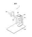
- FIG. 1 is a diagram illustrating a schematic configuration of an image processing system 1 according to an embodiment.
- 1 is an exploded view of an image processing system 1 according to an embodiment.
- 2 is a hardware configuration diagram of the image reading apparatus 100.
- FIG. It is a figure which shows schematic structure of 1st CPU110.
- 2 is a hardware configuration diagram of an image projection apparatus 200.
- FIG. It is a flowchart which shows the operation
- It is a schematic diagram for demonstrating each input image. It is a schematic diagram for demonstrating each input image. It is a schematic diagram for demonstrating each input image. It is a schematic diagram for demonstrating each input image. It is a schematic diagram for demonstrating each input image.
- FIG. 1A is a diagram showing a schematic configuration of an image processing system according to the embodiment
- FIG. 1B is an exploded view of the image processing system.
- the image processing system 1 includes an image reading apparatus 100, an image projection apparatus 200, a mounting table 300, an installation table 400, a support member 500, and the like.
- the image reading apparatus 100 is an apparatus that is disposed above an object mounted on the mounting table 300 and images the object.
- the image reading apparatus 100 is, for example, a multi-function mobile phone (so-called smartphone) having a camera or the like, a tablet PC (Personal Computer), a portable information terminal, or the like.
- An object to be imaged by the image reading apparatus 100 is, for example, an object having a three-dimensional shape.
- the image projection apparatus 200 is an apparatus that is disposed above an object mounted on the mounting table 300 and projects a projection image toward the object, for example, a projector.
- the mounting table 300 is a table on which an object to be imaged by the image reading apparatus 100 is mounted.
- the installation table 400 is a table on which the image reading apparatus 100 is installed.
- the installation table 400 has a U-shape including a pedestal 401, a connection member 402, and an installation member 403.
- the pedestal 401 has a planar shape and is attached to a predetermined position 301 of the mounting table 300 with screws or the like. Note that the pedestal 401 may be simply placed without being attached to the predetermined position 301.
- the connecting member 402 has a planar shape and extends from the base 401 upward in the vertical direction.
- the installation member 403 has a planar shape, and is attached to the upper end in the vertical direction of the connection member 402 in the same direction as the direction in which the base 401 is attached.
- the image reading apparatus 100 is placed on the installation member 403 so that the object placed on the placement table 300 can be imaged, that is, the imaging direction is vertically downward and the installation member 403 is not included in the imaging range. Is done.
- the support member 500 is a member that supports the image projection apparatus 200.
- the support member 500 has an L shape, is attached to a predetermined position 302 of the mounting table 300 with screws or the like, and extends from the mounting table 300 in the vertical direction.
- the image projection apparatus 200 is attached to the end of the support member 500 opposite to the end attached to the mounting table 300 by screws or the like.
- the image projecting device 200 is attached to the support member 500 so that a projected image can be projected toward an object mounted on the mounting table 300, that is, the projection direction is downward in the vertical direction.
- the installation table 400 and the support member 500 are arranged at predetermined predetermined positions 301 and 302 of the mounting table 300, respectively, so that the image reading device 100, the image projection device 200, and the mounting device are placed.
- the arrangement position of the mounting table 300 is fixed. Thereby, the positional relationship between the optical center and imaging direction of the imaging device of the image reading device 100, the optical center and projection direction of the image projection device 200, and the mounting surface of the mounting table 300 is kept constant.
- the support member 500 may be attached to the installation table 400 instead of being attached to the mounting table 300. Further, the image reading apparatus 100 and the installation table 400 may be integrally configured using, for example, an overhead type scanner apparatus or the like.
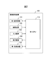
- FIG. 2 is a hardware configuration diagram of the image reading apparatus 100.
- the image reading apparatus 100 includes a first communication circuit 101, an imaging device 102, an input device 103, a display device 104, a first storage device 105, a first CPU (Central Processing Unit) 110, and the like.
- a first communication circuit 101 As shown in FIG. 2, the image reading apparatus 100 includes a first communication circuit 101, an imaging device 102, an input device 103, a display device 104, a first storage device 105, a first CPU (Central Processing Unit) 110, and the like.
- CPU Central Processing Unit
- the first communication circuit 101 includes an antenna that transmits and receives radio signals and a radio communication interface circuit that transmits and receives signals through a radio communication line according to a predetermined communication protocol such as a wireless LAN (Local Area Network).
- the first communication circuit 101 communicates with the image projection apparatus 200 via an access point (not shown), transmits information output from the first CPU 110 to the image projection apparatus 200, and receives information received from the image projection apparatus 200 from the first CPU 110. Output to.
- the first communication circuit 101 may directly communicate with the image projection apparatus 200 without using an access point. Further, the first communication circuit 101 may communicate with the image projection device 200 by short-range wireless communication.
- the imaging device 102 has an imaging sensor that images a target object.
- the image sensor includes an image sensor and an optical system that forms an image of an object on the image sensor. Each image sensor outputs an analog value corresponding to each color of RGB.
- the image sensor is a CCD (Charge-Coupled Device), CMOS (Complementary Metal-Oxide Semiconductor) or the like arranged in one or two dimensions.
- the imaging device 102 converts each analog value output from the imaging sensor into a digital value to generate pixel data, and generates image data (hereinafter referred to as an input image) composed of the generated pixel data.
- This input image is color image data in which each pixel data is composed of a total of 24 bits of RGB values represented by 8 bits for each RGB color, for example.
- the imaging device 102 outputs the generated input image to the first CPU 110.
- the input device 103 includes an input device such as a touch pad and an interface circuit that acquires a signal from the input device, and outputs a signal corresponding to a user operation to the first CPU 110.
- the display device 104 includes a display composed of liquid crystal, organic EL (Electro-Luminescence), and the like, and an interface circuit that outputs image data to the display, and displays the image data output from the first CPU 110.
- a display composed of liquid crystal, organic EL (Electro-Luminescence), and the like
- an interface circuit that outputs image data to the display, and displays the image data output from the first CPU 110.
- the first storage device 105 includes a volatile semiconductor memory such as a RAM (Random Access Memory), a non-volatile semiconductor memory such as a ROM (Read Only Memory), and the like. Further, the first storage device 105 stores computer programs, databases, tables, various images, and the like that are used in various processes of the image reading apparatus 100.
- the computer program may be installed in the first storage device 14 using a known setup program or the like from a computer-readable portable recording medium.
- the portable recording medium is, for example, a CD-ROM (compact disk read only memory) or a DVD-ROM (digital versatile disk read only memory).
- the first storage device 105 has a positional relationship between the optical center of the imaging device 102 and the optical center of the image projection device 200, a positional relationship between the optical center of the imaging device 102 and the mounting surface of the mounting table 300, and the like.
- a positional relationship between the optical center of the imaging apparatus 102 and the optical center of the image projection apparatus 200 for example, a vector from the optical center of the imaging apparatus 102 to the optical center of the image projection apparatus 200 is stored.
- the distance from the optical center of the imaging device 102 to the mounting surface of the mounting table 300, the mounting of the mounting table 300 in the imaging direction of the imaging device 102 The angle with respect to the surface is stored. These pieces of information are measured in advance when the image processing system 1 is shipped or installed.
- the first CPU 110 is connected to the first communication circuit 101, the imaging device 102, the input device 103, the display device 104, and the first storage device 105, and controls each of these units.
- the first CPU 110 performs data transmission / reception control with the image projection device 200 via the first communication circuit 101, image generation control of the imaging device 102, input control of the input device 103, display control of the display device 104, and the first storage device 105. Control and so on.
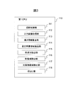
- FIG. 3 is a diagram showing a schematic configuration of the first CPU 110.
- the first CPU 110 includes a projection control unit 111, an input image acquisition unit 112, a height information calculation unit 113, an estimated background region extraction unit 114, a color component extraction unit 115, a shadow region detection unit 116, and an object region. It has a detection unit 117, a cutout unit 118, and the like.
- Each of these units is a functional module implemented by software operating on the processor.
- Each of these units may be composed of an independent integrated circuit, a microprocessor, firmware, and the like.
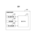
- FIG. 4 is a hardware configuration diagram of the image projection apparatus 200.
- the image projection apparatus 200 includes a second communication circuit 201, a projection apparatus 202, a second storage device 203, a second CPU 210, and the like.
- a second communication circuit 201 As shown in FIG. 4, the image projection apparatus 200 includes a second communication circuit 201, a projection apparatus 202, a second storage device 203, a second CPU 210, and the like.
- the image projection apparatus 200 includes a second communication circuit 201, a projection apparatus 202, a second storage device 203, a second CPU 210, and the like.
- each part of the image projector 200 will be described in detail.
- the second communication circuit 201 has the same interface circuit as the first communication circuit 101 of the image reading apparatus 100.
- the second communication circuit 201 communicates with the image reading apparatus 100, transmits information output from the second CPU 210 to the image reading apparatus 100, and outputs information received from the image reading apparatus 100 to the second CPU 210.
- the projection device 202 includes a light source, an optical system, and the like, and projects an image output from the second CPU 210 toward an object.
- the second storage device 203 includes a volatile semiconductor memory such as a RAM, a non-volatile semiconductor memory such as a ROM, and the like.
- the second storage device 203 stores a computer program, a database, a table, various images, and the like used for various processes of the image projection apparatus 200.
- the computer program may be installed in the second storage device 203 using a known setup program or the like from a computer-readable portable recording medium such as a CD-ROM or DVD-ROM.
- the second CPU 210 is connected to the second communication circuit 201, the projection device 202, and the second storage device 203, and controls these components.
- the second CPU 210 performs data transmission / reception control with the image reading device 100 via the second communication circuit 201, image projection control of the projection device 202, control of the second storage device 203, and the like.
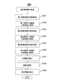
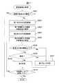
- FIG. 5 is a flowchart showing the operation of area extraction processing by the image reading apparatus 100.
- the operation of the area extraction process will be described with reference to the flowchart shown in FIG.
- the operation flow described below is mainly executed by the first CPU 110 in cooperation with each element of the image reading apparatus 100 based on a program stored in the first storage device 105 in advance.
- the first CPU 110 performs a height information calculation process (step S101).
- the first CPU 110 calculates the height information of each pixel in an input image (hereinafter sometimes referred to as a projection input image) obtained by capturing an object on which the projection image is projected.
- the projection input image is an example of the input image. Details of the height information calculation process will be described later.
- the first CPU 110 performs a background color determination process (step S102).
- the background color determination process the first CPU 110 determines a background color component in an input image (hereinafter, also referred to as a non-projection input image) obtained by capturing an object on which a projection image is not projected.
- the non-projection input image is an example of a second input image. Details of the background color determination processing will be described later.
- the first CPU 110 performs a shadow area detection process (step S103).
- the first CPU 110 detects a shadow area in which a shadow appears in the projection input image and the non-projection input image. Details of the shadow area detection processing will be described later.
- the first CPU 110 performs target area detection processing (step S104).
- the target area detection process the first CPU 110 detects a target area where the target is present in the projection input image and the non-projection input image. Details of the object region detection process will be described later.
- the first CPU 110 generates a cut-out image obtained by cutting out the detected object region from the non-projection input image, stores the cut-out image in the first storage device 105 (step S105), and ends a series of steps.
- the user can use the input device 103 to display the cut-out image stored in the first storage device 105 on the display device 104 or transmit it to another device.
- the first CPU 110 may convert the cut image into a three-dimensional image using the height information calculated in the height information calculation process. In the three-dimensional image, height information is stored in association with the pixel value for each pixel arranged two-dimensionally, and the three-dimensional image is displayed on the display device 104 in a three-dimensional manner based on the height information of each pixel. Is done.
- the first CPU 110 switches the viewpoint of the displayed 3D image in accordance with an instruction from the user using the input device 103.
- FIG. 6 is a flowchart showing an example of the operation of the height information calculation process. The operation flow shown in FIG. 6 is executed in step S101 of the flowchart shown in FIG.
- the projection control unit 111 first transmits a first request signal for requesting to project the first projection image toward the object to the image projection device 200 via the first communication circuit 101 ( Step S201).
- the first request signal includes the first projection image.
- the first projected image is a striped pattern or a lattice pattern image. In the embodiment described later, an example in which a striped image is used is shown as an example.
- the second CPU 210 of the image projection apparatus 200 When receiving the first request signal via the second communication circuit 201, the second CPU 210 of the image projection apparatus 200 stores the first projection image included in the first request signal in the second storage device 203 and stores it in the projection apparatus 202. Project.
- the first projection image is stored in advance in the second storage device 203 of the image projection device 200, and the first CPU 110 transmits a first request signal including identification information of the first projection image instead of the first projection image. May be.
- the imaging device 102 generates a first projection input image obtained by imaging the object on which the first projection image is projected, and outputs the first projection input image to the first CPU 110.
- the input image acquisition unit 112 acquires the first projection input image and stores it in the first storage device 105 (step S202).
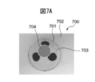
- FIG. 7A to 7D are schematic diagrams for explaining each input image captured by the imaging apparatus 102.
- FIG. An image 700 illustrated in FIG. 7A is an example of a non-projection input image.
- the non-projection input image 700 is an image obtained by capturing a teacup 701 placed on the placement table 300 as an object.
- the tea bowl 701 has a plain portion 703 having the same color as the background 702 in which the mounting table 300 is reflected, and a pattern 704 having a color different from the background 702.
- the first projection input image 710 is an image obtained by capturing a teacup 701 in which a predetermined sine wave pattern is projected as the first projection image.
- the sine wave pattern has a striped pattern in which a white portion 711 and a predetermined color portion 712 other than white are periodically repeated.
- the fringe due to the sine wave pattern is a straight line, but on the teacup 701 having a swelled shape with respect to the mounting table 300, the fringe due to the sine wave pattern is distorted and does not become a straight line.
- the projection control unit 111 transmits a second request signal for requesting to project the second projection image toward the object to the image projection device 200 via the first communication circuit 101 (step S203).
- the second request signal includes the second projection image.
- the second projected image is a striped or lattice pattern image.
- the second CPU 210 of the image projection device 200 receives the second request signal via the second communication circuit 201, the second projection image included in the second request signal is stored in the second storage device 203 and stored in the projection device 202. Project.
- the imaging apparatus 102 generates a second projection input image obtained by imaging the object on which the second projection image is projected, and outputs the second projection input image to the first CPU 110.
- the input image acquisition unit 112 acquires the second projection input image and stores it in the first storage device 105 (step S204).
- the second projection input image 720 is an image obtained by capturing a bowl 701 in which a sine wave pattern whose phase is shifted by ⁇ / 2 from the sine wave pattern of the first projection image is projected as the second projection image. It is.
- the white portion 721 and the predetermined color portion 722 are respectively shifted in phase by ⁇ / 2 from the position where the white portion 711 and the predetermined color portion 712 are projected in the first projection input image 710. Is projected.
- the projection control unit 111 transmits a third request signal for requesting to project the third projection image toward the object to the image projection device 200 via the first communication circuit 101 (step S205).
- the third request signal includes the third projection image.
- the third projected image is a striped or lattice pattern image.
- the second CPU 210 of the image projection apparatus 200 When receiving the third request signal via the second communication circuit 201, the second CPU 210 of the image projection apparatus 200 stores the third projection image included in the third request signal in the second storage device 203 and stores it in the projection apparatus 202. Project.
- the imaging apparatus 102 generates a third projection input image obtained by imaging the object on which the third projection image is projected, and outputs the third projection input image to the first CPU 110.
- the input image acquisition unit 112 acquires the third projection input image and stores it in the first storage device 105 (step S206).
- An image 730 shown in FIG. 7D is an example of a third projection input image.
- the third projection input image 730 is an image of a tea bowl 701 in which a sine wave pattern whose phase is further shifted by 2 ⁇ / 3 from the sine wave pattern of the second projection image is projected as the third projection image. It is an image.
- the white portion 731 and the predetermined color portion 732 are further shifted in phase by 2 ⁇ / 3 from the position where the white portion 721 and the predetermined color portion 722 are projected in the second projection input image 720, respectively. Projected to position.
- the height information calculation unit 113 calculates the phase value of the sine wave pattern at the position of each pixel from the luminance value of each pixel in the first projection input image, the second projection input image, and the third projection input image. (Step S207).
- the height information calculation unit 113 calculates the luminance value I (x, y) of the pixel located at the coordinates (x, y) in each projection input image by the following equation (1).
- R, G, and B are color values for each RGB color in each projection input image.
- the height information calculation unit 113 calculates the phase value phase (x, y) of the sine wave pattern at the position of the coordinates (x, y) in each projection input image by the following equation (2).
- I 1 (x, y) is the luminance value of the pixel located at the coordinates (x, y) in the first projection input image.
- I 2 (x, y) is a luminance value of the pixel located at the coordinates (x, y) in the second projection input image.
- I 3 (x, y) is the luminance value of the pixel located at the coordinates (x, y) in the third projection input image.
- I 1 (x, y), I 2 (x, y), and I 3 (x, y) are represented as I 1 , I 2 , and I 3 , respectively.
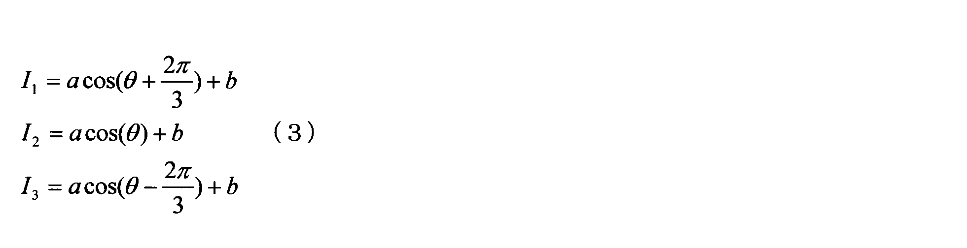
- I 1 , I 2 , and I 3 can be expressed by the following formula (3), respectively.
- a is the intensity of the projection light
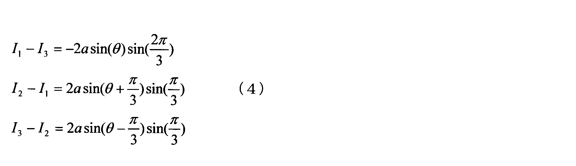
- b is the intensity of the ambient light. Therefore, the following formula (4) is established. From the equation (4), the following equation (5) is established. Equation (2) is derived from this equation (5).
- the height information calculation unit 113 performs phase connection by adding 2 ⁇ for each period of the sine wave pattern to the phase value of each pixel calculated by Expression (2).
- the phase value subjected to phase coupling is referred to as an absolute phase value.
- the height information calculation unit 113 calculates the depth for each corresponding pixel in the first projection input image, the second projection input image, and the third projection input image (step S208). Depth is the distance from the optical center of the imaging device 102 to the object shown in the pixel.
- the height information calculation unit 113 connects the pixels on the projection input image having the same absolute phase value, and associates the group of the connected pixels with each line of the sine wave pattern on the projection image. Do. Furthermore, the height information calculation unit 113 calculates the distance from the pixels located at both ends of the group for each pixel included in each group. Based on the calculated distance, the height information calculation unit 113 associates each pixel included in each group with each pixel on the line of the sine wave pattern associated with the group. Then, the height information calculation unit 113 calculates the depth of each pixel on the projection input image based on the positional relationship with the pixel on the associated projection image.
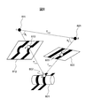
- FIG. 8 is a schematic diagram for explaining a depth calculation method.
- an object 801 is an object
- a point c 811 is an optical center of the imaging device 102
- a plane 812 is an imaging surface of the projection device 202
- a point p 821 is an optical center of the projection device 202.
- a plane 822 is a projection plane of the projection device 202.
- the s ′ point 813 on the imaging surface 812 and the s ′′ point 823 on the projection surface 822 correspond to the s point 802 on the object 801 and are associated with each other.
- the positional relationship between the optical center of the imaging device 102 and the optical center of the projection device 202 is kept constant.
- a vector T cp from the optical center c point 811 of the imaging apparatus 102 to the optical center p point 821 of the projection apparatus 202 is stored in the first storage device 105 in advance.
- T c-s ′ is a vector from the optical center c point 811 of the imaging apparatus 102 to the s ′ point 813 on the imaging surface 812.
- an angle ⁇ p formed by a vector from the c point 811 to the p point 821 and a vector from the p point 821 to the s point 802 is calculated by the following equation (7).
- T p-s ′′ is a vector from the optical center p point 821 of the projection device 202 toward the s ′′ point 823 on the projection plane 822.
- the depth of the s ′ point 813 on the imaging surface 812 is represented by the absolute value of the vector T cs from the optical center c point 821 of the imaging device 102 to the optical center p point 811 of the projection device 202. This depth is calculated by the following equation (8) by applying the principle of triangulation to a triangle having apexes c, p, and s.
- the height information calculation unit 113 calculates the height information of each pixel in the first projection input image, the second projection input image, and the third projection input image based on the calculated depth (step S209).
- the height information calculation unit 113 performs imaging in a direction orthogonal to the mounting surface based on the depth of the s ′ point 813 on the imaging surface 812 and the angle of the imaging direction of the imaging device 102 with respect to the mounting surface of the mounting table 300. The distance from the optical center of the apparatus 102 to the s point 802 on the object 801 is calculated. In addition, the height information calculation unit 113 determines the distance from the placement surface to the s point 802 on the object 801 based on the calculated distance and the distance from the optical center of the imaging device 102 to the placement surface of the placement table 300. Calculate the height. Then, the height information calculation unit 113 stores the calculated height from the placement surface in the first storage device 105 as pixel height information corresponding to the s ′ point 813 on the imaging surface 812.
- the height information calculation unit 113 calculates the height information of each pixel using the first projection input image, the second projection input image, and the third projection input image.
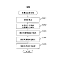
- FIG. 9 is a flowchart showing an example of the operation of the background color determination process. The operation flow shown in FIG. 9 is executed in step S102 of the flowchart shown in FIG.
- the projection control unit 111 transmits a stop request signal for requesting to stop the projection of the projection image to the image projection apparatus 200 via the first communication circuit 101 (step S301).
- the second CPU 210 of the image projection apparatus 200 When the second CPU 210 of the image projection apparatus 200 receives the stop request signal via the second communication circuit 201, the second CPU 210 causes the projection apparatus 202 to stop projecting the projection image.
- the imaging device 102 generates a non-projection input image obtained by capturing an object on which the projection image is not projected, and outputs the non-projection input image to the first CPU 110.
- the input image acquisition unit 112 acquires a non-projection input image and stores it in the first storage device 105 (step S302).
- the estimated background region extraction unit 114 estimates the target object region estimated from the non-projection input image based on the height information of each pixel calculated by the height information calculation unit 113. Is extracted (step S303).
- the estimated background area extraction unit 114 determines, for each pixel in the non-projection input image, whether the height indicated by the height information of the pixel corresponding to each pixel exceeds a predetermined value.
- the predetermined value is 0, for example.
- the predetermined value may be a value larger than 0 (for example, a value corresponding to 1 mm) in consideration of the influence of noise or calculation error of height information.
- the estimated background area extraction unit 114 extracts pixels whose height indicated by the height information exceeds a predetermined value as candidate pixels in which the object is shown.
- the estimated background area extraction unit 114 groups the extracted pixels by labeling and extracts them as an estimation object area.
- the estimated background region extraction unit 114 extracts an estimated background region that is estimated to include the background from the non-projection input image based on the extracted estimation target region (step S304).
- the estimated background area extraction unit 114 extracts a circumscribed rectangle that includes all of the extracted estimated object areas, and extracts a rectangle that has a predetermined length margin outside the extracted circumscribed rectangle.
- the estimated background area extraction unit 114 extracts a band-shaped area having a predetermined width (for example, 5 pixels) surrounding the extracted rectangle so as to be adjacent to the rectangle as the estimated background area.
- the estimated background area extraction unit 114 may extract a band-like area directly adjacent to the extracted circumscribed rectangle as the estimated background area. Further, the estimated background area extraction unit 114 may extract only the four corner areas of the band-shaped area surrounding the extracted rectangle as the estimated background area.
- FIG. 10 is a schematic diagram for explaining the estimated background region.
- An image 1000 illustrated in FIG. 10 is an example of a non-projection input image.
- an area 1001 is an estimation object area
- a rectangle 1002 is a circumscribed rectangle of the estimation object area 1001
- a rectangle 1003 is a rectangle with a margin 1004 with respect to the rectangle 1002.
- a band-like region 1005 is an estimated background region.
- the four corner regions 1006 to 1009 of the band-like region may be estimated background regions.
- the color component extraction unit 115 determines a background color component in the non-projection input image based on the pixels in the estimated background region (step S305), and ends a series of steps.
- the color component extraction unit 115 calculates an average value of each color value for each RGB color for each pixel in the estimated background region, and determines each calculated average value as a background color component.
- the estimated background area extraction unit 114 sets not only the entire area outside the estimated object area but only the area near the estimated object area as the estimated background area.
- the color component extraction unit 115 can accurately calculate the background color component from a region not affected by disturbance such as illumination. Further, since the color component extraction unit 115 does not calculate the background color component from the entire region outside the target object candidate region, the processing load related to the color component calculation can be reduced. Furthermore, the color component extraction unit 115 can further reduce the processing load related to the color component calculation by using only the four corner regions of the band-like region as the estimated background region.
- FIG. 11 is a flowchart showing an example of the operation of the shadow area detection process. The operation flow shown in FIG. 11 is executed in step S103 of the flowchart shown in FIG.
- the shadow area detection unit 116 determines whether or not the background color component determined by the color component extraction unit 115 is black (step S401).
- Black means a color in a range that absorbs light.
- the shadow region detection unit 116 determines that the background color component is black when all the RGB color values determined as the background color components are 32 or less, and if any of the color values is greater than 32, It is determined that the background color component is not black.
- the shadow area detection unit 116 determines that the background color component is black, the shadow area detection unit 116 determines that the background is not affected by the shadow, and ends the series of steps without detecting the shadow area.
- the projection control unit 111 transmits a first color request signal for requesting to project light of the first color toward the object in the first communication circuit. It transmits to the image projection apparatus 200 via 101 (step S402).
- the first color is, for example, green.
- the second CPU 210 of the image projection apparatus 200 When receiving the first color request signal via the second communication circuit 201, the second CPU 210 of the image projection apparatus 200 causes the projection apparatus 202 to project light of the first color toward the object.
- the imaging device 102 generates a first color input image obtained by imaging the object on which the first color light is projected, and outputs the first color input image to the first CPU 110.
- the input image acquisition unit 112 acquires the first color input image and stores it in the first storage device 105 (step S403).
- FIG. 12A is a schematic diagram for explaining the first color input image.
- An image 1200 illustrated in FIG. 12A is an example of a first color input image.
- a first color input image 1200 illustrated in FIG. 12A is an image obtained by capturing an object 1202 having a black pattern 1201. As illustrated in FIG. 12A, the object 1202 and the background 1203 have a first color, but the black pattern 1201 absorbs the first color and does not have the first color. Further, a shadow 1204 is generated around the object 1202 by the first color light. The shadow 1204 does not have the color of the first color, and becomes lighter gray than black due to natural light or ambient light.
- the projection control unit 111 transmits a second color request signal for requesting to project light of the second color toward the object to the image projection apparatus 200 via the first communication circuit 101 (Ste S404).
- the second color is a color different from the first color, for example, pink.
- the second CPU 210 of the image projection apparatus 200 When receiving the second color request signal via the second communication circuit 201, the second CPU 210 of the image projection apparatus 200 causes the projection apparatus 202 to project light of the second color toward the object.
- the imaging device 102 generates a second color input image obtained by imaging the object on which the second color light is projected, and outputs the second color input image to the first CPU 110.
- the input image acquisition unit 112 acquires the second color input image and stores it in the first storage device 105 (step S405).
- FIG. 12B is a schematic diagram for explaining the second color input image.
- An image 1210 shown in FIG. 12B is an example of a second color input image.
- a second color input image 1210 illustrated in FIG. 12B is an image obtained by capturing the same object 1212 as the object 1202 illustrated in FIG. 12A.
- the object 1212 and the background 1213 have a second color, but the black pattern 1211 absorbs the second color and does not have the second color.
- a shadow 1214 is generated around the object 1212 by the second color light.
- the shadow 1214 does not have the second color, and becomes a lighter gray than black due to natural light or ambient light, similar to the shadow 1204 illustrated in FIG. 12A.
- steps S406 to S410 is executed for each pixel combination existing at a corresponding position in the first color input image and the second color input image.
- the shadow area detection unit 116 determines whether or not the difference between the color components of the pixel in the first color input image and the pixel in the second color input image corresponding to the pixel is equal to or less than the threshold (step). S406).
- the shadow area detection unit 116 calculates the difference between the color values of the two pixels for each color of RGB, and calculates the sum of the calculated differences as the difference between the color components.
- the threshold value is set to, for example, a color difference (for example, 20) that allows a person to visually distinguish the color difference on the image.
- the shadow area detection unit 116 When the difference between the color components of each pixel is larger than the threshold value, the shadow area detection unit 116 has each pixel having a first color tint and a second color tint, and the pixel has a shadow. It is determined that there is no image (step S407).
- the shadow area detection unit 116 determines whether the color component of each pixel in the first color input image and the second color input image is black. (Step S408). The shadow area detection unit 116 determines whether or not the color component of each pixel is black, as in step S401.
- the shadow region detection unit 116 determines that the black object or background is reflected in the pixel and no shadow is captured (step S407).
- the shadow area detection unit 116 determines that each pixel has a gray color and that the pixel has a shadow. Then, the shadow area detection unit 116 detects a position in each projection input image and non-projection input image corresponding to the position of the pixel as a shadow area (step S409).
- the shadow area detection unit 116 determines whether or not processing has been performed for all pixel combinations existing at corresponding positions in the first color input image and the second color input image (step S410). When there is a pixel combination that has not yet been processed, the shadow area detection unit 116 returns the process to step S406 and repeats the processes of steps S406 to S410. When the process has been performed for all pixel combinations, a series of steps are performed. Exit.
- the shadow area detection unit 116 shadows the positions in the projection input image and the non-projection input image corresponding to the positions of the pixel combinations in which the difference in color components of the pixels is equal to or less than the threshold value and each pixel is not black. Detect as a region.
- FIG. 13 is a flowchart showing an example of the operation of the object area detection process. The operation flow shown in FIG. 13 is executed in step S104 of the flowchart shown in FIG.
- steps S501 to S506 are executed for each pixel combination existing at a corresponding position in the first to third projection input images, the non-projection input image, and the first to second color input images.
- the object region detection unit 117 determines whether or not the shadow region detection unit 116 determines that a shadow is reflected in a pixel of interest in the first color input image and the second color input image ( Step S501).
- the target object region detection unit 117 determines that the target object is not in the pixel (step S502).
- the target area detection unit 117 sets the height indicated by the height information of the pixel in the projection input image corresponding to the pixel to a predetermined value. It is determined whether or not it exceeds (step S503).
- the predetermined value is the same value as the predetermined value used for extracting the object candidate region.
- the predetermined value may be a value different from the predetermined value used for extracting the target object candidate area.
- the object area detection unit 117 determines that the object is captured in the pixel when the height indicated by the height information of the pixel exceeds a predetermined value (step S504).
- the color component extraction unit 115 extracts the color component of the pixel in the non-projection input image corresponding to the pixel. Then, the color component extraction unit 115 determines whether or not the difference between the extracted color component and the background color component is greater than or equal to a predetermined value (step S505).
- the color component extraction unit 115 calculates the difference between the extracted color value and the background color value for each color of RGB, and calculates the sum of the calculated differences as the difference between the color components.
- the predetermined value is set to, for example, a color difference (for example, 20) that allows a person to visually distinguish the color difference on the image.
- the object area detection unit 117 determines that the object is reflected in the pixel (step S504).
- the object region detection unit 117 determines that the object is not captured in the pixel (step S505).
- the object area detection unit 117 determines whether or not the process has been executed for all the pixels (step S506). If there is a pixel that has not yet been processed, the object area detection unit 117 returns the process to step S501 and repeats the processes of steps S501 to S506.
- the object area detection unit 117 when the processing is executed for all the pixels, the object area detection unit 117 generates a mask image for identifying the area where the object is reflected and the area where the object is not captured (step S507).
- the object region detection unit 117 uses a pixel corresponding to a pixel determined to be an object as a valid pixel, and an image having a pixel corresponding to a pixel determined to be an object as an invalid pixel as a mask image.
- the object region detection unit 117 groups the effective pixels by labeling in the mask image (step S508).
- the object area detection unit 117 detects each pixel at a position corresponding to a position where a group of effective pixels in the mask image exists in each projection input image and non-projection input image as an object area (Ste S509), a series of steps is finished.
- the object area detection unit 117 detects the object area in each projection input image based on the height information of each pixel in each projection input image. As a result, the object area detection unit 117 can detect the object area with high accuracy even for the object 701 having a color similar to the background, as shown in FIGS. 7A to 7D.
- the object area detection unit 117 detects the object area in the non-projection input image based on the color component of each pixel and the background color component in the non-projection input image. Thereby, even if it is the target object which has a low planar shape, the target object area
- the object area detection unit 117 detects the object area so as not to include the shadow area detected by the shadow area detection unit 116. As a result, the object region detection unit 117 can prevent a shadow portion from being included in the cut-out image even when a shadow is generated by an object having a three-dimensional shape. In addition, since the projection image projected from the image projection apparatus 200 is not projected onto the shadow area, the image reading apparatus 100 cannot correctly calculate the height information. The object area detection unit 117 detects the object area so as not to include the shadow area, thereby detecting the object area with high accuracy without using the height information calculated in the area with low reliability. be able to.
- step S501 may be omitted.
- the object area detection unit 117 detects the object area based on the height information of each pixel regardless of whether or not each pixel has a shadow.
- the process of step S503 may be omitted. In that case, when the height indicated by the height information of each pixel is equal to or less than a predetermined value, the target object area detection unit 117 determines that the target object is not captured in the pixel. Further, the order of the processing in step S503 and step S505 may be reversed.
- the object region detection unit 117 detects the object region based on the height information of the pixel. Also in these cases, the object region detection unit 117 can detect the object with high accuracy.
- the object region detection unit 117 calculates an object degree indicating the likelihood that the object is reflected for each pixel, and the object is detected in each pixel depending on whether the object degree is a predetermined value or more. You may determine whether it is reflected. In that case, the object region detection unit 117 increases the object degree so that the object degree increases as the height indicated by the height information of each pixel increases, and the object degree decreases as the height decreases. calculate. Further, the object region detection unit 117 increases the object degree as the difference between the color component of each pixel and the background color component increases, and the object degree as the difference between the color component and the background color component decreases. The degree of object is calculated so as to be low. Thereby, the target object area
- the object area detection unit 117 may generate an edge image based on the height information of each pixel and detect the object based on the edge image.
- the object region detection unit 117 determines the absolute value of the difference in height between the adjacent pixels in the horizontal or vertical direction (hereinafter referred to as the adjacent difference) with respect to the height indicated by the height information of each pixel in the projection input image. (Referred to as value).
- the object region detection unit 117 extracts pixels whose adjacent difference values in the horizontal or vertical direction exceed a threshold value as edge pixels, and generates an image including the edge pixels as an edge image.
- the object area detection unit 117 groups the edge pixels in the generated edge image by labeling, and detects an area surrounded by the grouped edge pixels as the object area. Also by this, the object area detection unit 117 can detect the object with high accuracy.
- the object region detection unit 117 does not detect the object region based on the color component of each pixel in the non-projection input image, but based on the color component of each pixel in the projection input image. May be detected.
- the estimated background area extraction unit 114 extracts the estimated background area from the projection input image based on the height information of each pixel in the projection input image.
- the color component extraction unit 115 determines a background color component in the projection input image based on the pixels in the estimated background region, and extracts a color component of each pixel in the projection input image. Then, the object area detection unit 117 detects the object area based on the background color component and the color component of each pixel in the projection input image.
- the image processing system 1 can easily and accurately target an object region in an image obtained by capturing an object. It became possible to detect. In particular, the image processing system 1 can detect the object region with high accuracy even when the whole or a part of the color of the object is similar to the background color by using the height information. became. In addition, the image processing system 1 can detect an object region without using special background equipment such as a blue back and special lighting equipment such as a backlight.
- special background equipment such as a blue back and special lighting equipment such as a backlight.
Landscapes
- Engineering & Computer Science (AREA)
- Physics & Mathematics (AREA)
- General Physics & Mathematics (AREA)
- Theoretical Computer Science (AREA)
- Computer Vision & Pattern Recognition (AREA)
- Multimedia (AREA)
- Signal Processing (AREA)
- Artificial Intelligence (AREA)
- Optics & Photonics (AREA)
- Geometry (AREA)
- Controls And Circuits For Display Device (AREA)
- Projection Apparatus (AREA)
- Length Measuring Devices By Optical Means (AREA)
- Image Analysis (AREA)
Abstract
Description






100 画像読取装置
111 投影制御部
112 入力画像取得部
113 高さ情報算出部
114 推定背景領域抽出部
115 色成分抽出部
116 影領域検出部
117 対象物領域検出部
118 切出し部
200 画像投影装置
Claims (8)
- 対象物に向けて縞模様又は格子模様の投影画像を投影する画像投影装置と、
前記投影画像が投影された対象物を撮像する画像読取装置と、を有し、
前記画像読取装置は、
前記投影画像が投影された対象物を撮像した入力画像を取得する入力画像取得部と、
前記入力画像を用いて、前記入力画像内の各画素の高さ情報を算出する高さ情報算出部と、
前記入力画像内の各画素の高さ情報に基づいて、前記入力画像において対象物が存在する対象物領域を検出する対象物領域検出部と、
を有することを特徴とする画像処理システム。 - 前記入力画像取得部は、前記投影画像が投影されていない対象物を撮像した第2入力画像をさらに取得し、
前記画像読取装置は、前記第2入力画像内の各画素の色成分を抽出する色成分抽出部をさらに有し、
前記対象物領域検出部は、さらに前記第2入力画像内の各画素の色成分に基づいて、前記第2入力画像において対象物が存在する第2対象物領域を検出する、請求項1に記載の画像処理システム。 - 前記画像読取装置は、前記入力画像内の各画素の高さ情報に基づいて、前記第2入力画像から、背景が写っていると推定される推定背景領域を抽出する推定背景領域抽出部をさらに有し、
前記色成分抽出部は、前記推定背景領域内の画素に基づいて、前記第2入力画像内の背景の色成分を決定し、
前記対象物領域検出部は、前記決定した背景の色成分に基づいて、前記第2対象物領域を検出する、請求項2に記載の画像処理システム。 - 前記画像投影装置は、さらに、前記対象物に向けて、第一色の光及び前記第一色と異なる第二色の光を投影し、
前記入力画像取得部は、前記第一色の光が投影された対象物を撮像した第一色入力画像と、前記第二色の光が投影された対象物を撮像した第二色入力画像と、をさらに取得し、
前記画像読取装置は、前記第一色入力画像と前記第二色入力画像で対応する位置に存在する画素組合せのそれぞれについて、各画素の色成分の差が閾値以下であるか否かと、各画素の色成分が黒色であるか否かとを判定し、各画素の色成分の差が閾値以下であり且つ各画素の色成分が黒色でない画素組合せの位置に対応する前記入力画像内の位置を影領域として検出する影領域検出部をさらに有し、
前記対象物領域検出部は、前記影領域検出部が検出した影領域を含まないように前記対象物領域を検出する、請求項3に記載の画像処理システム。 - 前記影領域検出部は、前記決定した背景の色成分が黒色である場合、前記影領域を検出しない、請求項4に記載の画像処理システム。
- 画像投影装置により縞模様又は格子模様の投影画像が投影された対象物を撮像した入力画像を取得する入力画像取得部と、
前記入力画像を用いて、前記入力画像内の各画素の高さ情報を算出する高さ情報算出部と、
前記入力画像内の各画素の高さ情報に基づいて、前記入力画像において対象物が存在する対象物領域を検出する対象物領域検出部と、
を有することを特徴とする画像読取装置。 - 画像投影装置及び画像読取装置を有する画像処理システムにおける領域検出方法であって、
前記画像投影装置が、対象物に向けて縞模様又は格子模様の投影画像を投影し、
前記画像読取装置が、
前記投影画像が投影された対象物を撮像した入力画像を取得し、
前記入力画像を用いて、前記入力画像内の各画素の高さ情報を算出し、
前記入力画像内の各画素の高さ情報に基づいて、前記入力画像において対象物が存在する対象物領域を検出する、
ことを含むことを特徴とする領域検出方法。 - 画像投影装置により縞模様又は格子模様の投影画像が投影された対象物を撮像した入力画像を取得し、
前記入力画像を用いて、前記入力画像内の各画素の高さ情報を算出し、
前記入力画像内の各画素の高さ情報に基づいて、前記入力画像において対象物が存在する対象物領域を検出する、
ことをコンピュータに実行させることを特徴とするコンピュータプログラム。
Priority Applications (3)
| Application Number | Priority Date | Filing Date | Title |
|---|---|---|---|
| PCT/JP2015/066778 WO2016199253A1 (ja) | 2015-06-10 | 2015-06-10 | 画像処理システム、画像読取装置、領域検出方法及びコンピュータプログラム |
| US15/580,918 US10247546B2 (en) | 2015-06-10 | 2015-06-10 | Image processing system and method for detecting a target object area based on height information |
| JP2017523033A JP6440836B2 (ja) | 2015-06-10 | 2015-06-10 | 画像処理システム、画像読取装置、領域検出方法及びコンピュータプログラム |
Applications Claiming Priority (1)
| Application Number | Priority Date | Filing Date | Title |
|---|---|---|---|
| PCT/JP2015/066778 WO2016199253A1 (ja) | 2015-06-10 | 2015-06-10 | 画像処理システム、画像読取装置、領域検出方法及びコンピュータプログラム |
Publications (1)
| Publication Number | Publication Date |
|---|---|
| WO2016199253A1 true WO2016199253A1 (ja) | 2016-12-15 |
Family
ID=57503209
Family Applications (1)
| Application Number | Title | Priority Date | Filing Date |
|---|---|---|---|
| PCT/JP2015/066778 Ceased WO2016199253A1 (ja) | 2015-06-10 | 2015-06-10 | 画像処理システム、画像読取装置、領域検出方法及びコンピュータプログラム |
Country Status (3)
| Country | Link |
|---|---|
| US (1) | US10247546B2 (ja) |
| JP (1) | JP6440836B2 (ja) |
| WO (1) | WO2016199253A1 (ja) |
Cited By (2)
| Publication number | Priority date | Publication date | Assignee | Title |
|---|---|---|---|---|
| WO2018142625A1 (ja) * | 2017-02-06 | 2018-08-09 | 株式会社Pfu | 画像読取補助装置および画像読取装置 |
| CN113793293A (zh) * | 2020-05-25 | 2021-12-14 | 中移(苏州)软件技术有限公司 | 轮廓检测方法、装置、系统及计算机可读存储介质 |
Families Citing this family (6)
| Publication number | Priority date | Publication date | Assignee | Title |
|---|---|---|---|---|
| WO2018145113A1 (en) | 2017-02-06 | 2018-08-09 | MODit3D, INC. | System and method for 3d scanning |
| CN111060027A (zh) * | 2019-12-09 | 2020-04-24 | 英特维科技(深圳)有限公司 | 一种三维检测系统及方法 |
| CN111626919B (zh) * | 2020-05-08 | 2022-11-15 | 北京字节跳动网络技术有限公司 | 图像合成方法、装置、电子设备及计算机可读存储介质 |
| CN113255658B (zh) * | 2020-12-31 | 2023-05-30 | 深圳怡化电脑股份有限公司 | 一种介质鉴定方法、装置、电子设备和存储介质 |
| CN114782616B (zh) * | 2022-06-20 | 2022-09-20 | 北京飞渡科技有限公司 | 模型处理方法、装置、存储介质及电子设备 |
| WO2026006888A1 (pt) * | 2024-07-04 | 2026-01-08 | Crmall Sistema De Informação De Marketing Ltda - Epp | Configuração construtiva aplicada a suporte para dispositivos eletrônicos |
Citations (3)
| Publication number | Priority date | Publication date | Assignee | Title |
|---|---|---|---|---|
| JPH1054709A (ja) * | 1996-08-09 | 1998-02-24 | Techno Horon:Kk | 顕微鏡を用いた3次元画像認識装置 |
| WO2008149923A1 (ja) * | 2007-06-07 | 2008-12-11 | The University Of Electro-Communications | 物体検出装置とそれを適用したゲート装置 |
| JP2013145441A (ja) * | 2012-01-13 | 2013-07-25 | Burein:Kk | 物体識別装置 |
Family Cites Families (14)
| Publication number | Priority date | Publication date | Assignee | Title |
|---|---|---|---|---|
| JP2919284B2 (ja) * | 1994-02-23 | 1999-07-12 | 松下電工株式会社 | 物体認識方法 |
| JP4012710B2 (ja) | 2001-02-14 | 2007-11-21 | 株式会社リコー | 画像入力装置 |
| JP2009031150A (ja) * | 2007-07-27 | 2009-02-12 | Omron Corp | 三次元形状計測装置、三次元形状計測方法、三次元形状計測プログラム、および記録媒体 |
| US7758097B2 (en) * | 2008-07-24 | 2010-07-20 | Honda Motor Co., Ltd. | Cover assembly for a vehicle storage compartment striker |
| US8284240B2 (en) * | 2008-08-06 | 2012-10-09 | Creaform Inc. | System for adaptive three-dimensional scanning of surface characteristics |
| NL2003364A (en) * | 2008-09-26 | 2010-03-29 | Asml Netherlands Bv | Lithographic apparatus and method. |
| JP2012014535A (ja) * | 2010-07-02 | 2012-01-19 | Nec Corp | 物体領域抽出システム、方法、及び、プログラム |
| EP2622576A4 (en) * | 2010-10-01 | 2017-11-08 | Saab AB | Method and apparatus for solving position and orientation from correlated point features in images |
| US9182221B2 (en) * | 2011-06-13 | 2015-11-10 | Canon Kabushiki Kaisha | Information processing apparatus and information processing method |
| US9217636B2 (en) * | 2012-06-11 | 2015-12-22 | Canon Kabushiki Kaisha | Information processing apparatus, information processing method, and a computer-readable storage medium |
| TWI485361B (zh) * | 2013-09-11 | 2015-05-21 | Univ Nat Taiwan | 三維形貌輪廓量測裝置及其方法 |
| JP6417099B2 (ja) * | 2014-03-13 | 2018-10-31 | キヤノン株式会社 | 計測装置、および物品の製造方法 |
| WO2015183550A1 (en) * | 2014-05-27 | 2015-12-03 | Bourbaki 13, Inc. | Determining three-dimensional information from projections or placement of two-dimensional patterns |
| JP6460938B2 (ja) * | 2015-07-30 | 2019-01-30 | 株式会社キーエンス | 測定対象物計測プログラム、測定対象物計測方法および拡大観察装置 |
-
2015
- 2015-06-10 JP JP2017523033A patent/JP6440836B2/ja not_active Expired - Fee Related
- 2015-06-10 US US15/580,918 patent/US10247546B2/en active Active
- 2015-06-10 WO PCT/JP2015/066778 patent/WO2016199253A1/ja not_active Ceased
Patent Citations (3)
| Publication number | Priority date | Publication date | Assignee | Title |
|---|---|---|---|---|
| JPH1054709A (ja) * | 1996-08-09 | 1998-02-24 | Techno Horon:Kk | 顕微鏡を用いた3次元画像認識装置 |
| WO2008149923A1 (ja) * | 2007-06-07 | 2008-12-11 | The University Of Electro-Communications | 物体検出装置とそれを適用したゲート装置 |
| JP2013145441A (ja) * | 2012-01-13 | 2013-07-25 | Burein:Kk | 物体識別装置 |
Cited By (4)
| Publication number | Priority date | Publication date | Assignee | Title |
|---|---|---|---|---|
| WO2018142625A1 (ja) * | 2017-02-06 | 2018-08-09 | 株式会社Pfu | 画像読取補助装置および画像読取装置 |
| JPWO2018142625A1 (ja) * | 2017-02-06 | 2019-06-27 | 株式会社Pfu | 画像読取補助装置および画像読取装置 |
| CN113793293A (zh) * | 2020-05-25 | 2021-12-14 | 中移(苏州)软件技术有限公司 | 轮廓检测方法、装置、系统及计算机可读存储介质 |
| CN113793293B (zh) * | 2020-05-25 | 2024-01-26 | 中移(苏州)软件技术有限公司 | 轮廓检测方法、装置、系统及计算机可读存储介质 |
Also Published As
| Publication number | Publication date |
|---|---|
| US20180328724A1 (en) | 2018-11-15 |
| JP6440836B2 (ja) | 2018-12-19 |
| US10247546B2 (en) | 2019-04-02 |
| JPWO2016199253A1 (ja) | 2017-11-09 |
Similar Documents
| Publication | Publication Date | Title |
|---|---|---|
| JP6440836B2 (ja) | 画像処理システム、画像読取装置、領域検出方法及びコンピュータプログラム | |
| US10083522B2 (en) | Image based measurement system | |
| US11375165B2 (en) | Image calibration for projected images | |
| CN107534751B (zh) | 显示设备及其图像显示方法 | |
| JP5951043B2 (ja) | 画像計測装置 | |
| JP6099457B2 (ja) | 画像処理装置、領域決定方法及びコンピュータプログラム | |
| CN104094082A (zh) | 虚拟尺 | |
| US8155387B2 (en) | Method and system for position determination using image deformation | |
| US20150369593A1 (en) | Orthographic image capture system | |
| TW201042235A (en) | Three-dimensional shape measuring device, three-dimensional shape measuring method, and three-dimensional shape measuring program | |
| JP6566768B2 (ja) | 情報処理装置、情報処理方法、プログラム | |
| CN109920003A (zh) | 相机标定检测方法、装置以及设备 | |
| WO2016018393A1 (en) | Touch region projection onto a touch-sensitive surface | |
| JP2016184362A (ja) | 入力装置、入力操作検出方法及び入力操作検出用コンピュータプログラム | |
| US20130331145A1 (en) | Measuring system for mobile three dimensional imaging system | |
| WO2019198446A1 (ja) | 検出装置、検出方法、情報処理装置、及び情報処理プログラム | |
| JP5651659B2 (ja) | 物体検出システムおよびプログラム | |
| JPWO2018167971A1 (ja) | 画像処理装置、制御方法及び制御プログラム | |
| KR101314101B1 (ko) | 3차원 계측 시스템 및 그 방법 | |
| JP2019169913A (ja) | 投影制御装置、投影装置、補正用画像投影方法及びプログラム | |
| JP6299269B2 (ja) | 画像処理システム、プログラム及び投影装置 | |
| KR20220134183A (ko) | 조명부를 구비한 균열 측정기구 및 이를 이용한 균열 측정방법 | |
| KR101996226B1 (ko) | 피사체의 3차원 위치 측정 장치 및 그 방법 | |
| Ukida et al. | Omni-directional 3d measurement by hyperbolic mirror cameras and pattern projection | |
| CN109323691B (zh) | 一种定位系统以及定位方法 |
Legal Events
| Date | Code | Title | Description |
|---|---|---|---|
| 121 | Ep: the epo has been informed by wipo that ep was designated in this application |
Ref document number: 15894938 Country of ref document: EP Kind code of ref document: A1 |
|
| ENP | Entry into the national phase |
Ref document number: 2017523033 Country of ref document: JP Kind code of ref document: A |
|
| WWE | Wipo information: entry into national phase |
Ref document number: 15580918 Country of ref document: US |
|
| NENP | Non-entry into the national phase |
Ref country code: DE |
|
| 122 | Ep: pct application non-entry in european phase |
Ref document number: 15894938 Country of ref document: EP Kind code of ref document: A1 |