WO2016194940A1 - 切断装置、及び切断データ生成プログラム - Google Patents
切断装置、及び切断データ生成プログラム Download PDFInfo
- Publication number
- WO2016194940A1 WO2016194940A1 PCT/JP2016/066161 JP2016066161W WO2016194940A1 WO 2016194940 A1 WO2016194940 A1 WO 2016194940A1 JP 2016066161 W JP2016066161 W JP 2016066161W WO 2016194940 A1 WO2016194940 A1 WO 2016194940A1
- Authority
- WO
- WIPO (PCT)
- Prior art keywords
- pattern
- processing unit
- cutting
- patterns
- holding member
- Prior art date
- Legal status (The legal status is an assumption and is not a legal conclusion. Google has not performed a legal analysis and makes no representation as to the accuracy of the status listed.)
- Ceased
Links
Images







Classifications
-
- B—PERFORMING OPERATIONS; TRANSPORTING
- B26—HAND CUTTING TOOLS; CUTTING; SEVERING
- B26D—CUTTING; DETAILS COMMON TO MACHINES FOR PERFORATING, PUNCHING, CUTTING-OUT, STAMPING-OUT OR SEVERING
- B26D5/00—Arrangements for operating and controlling machines or devices for cutting, cutting-out, stamping-out, punching, perforating, or severing by means other than cutting
- B26D5/005—Computer numerical control means
-
- B—PERFORMING OPERATIONS; TRANSPORTING
- B26—HAND CUTTING TOOLS; CUTTING; SEVERING
- B26F—PERFORATING; PUNCHING; CUTTING-OUT; STAMPING-OUT; SEVERING BY MEANS OTHER THAN CUTTING
- B26F1/00—Perforating; Punching; Cutting-out; Stamping-out; Apparatus therefor
- B26F1/38—Cutting-out; Stamping-out
- B26F1/3806—Cutting-out; Stamping-out wherein relative movements of tool head and work during cutting have a component tangential to the work surface
- B26F1/3813—Cutting-out; Stamping-out wherein relative movements of tool head and work during cutting have a component tangential to the work surface wherein the tool head is moved in a plane parallel to the work in a coordinate system fixed with respect to the work
-
- B—PERFORMING OPERATIONS; TRANSPORTING
- B26—HAND CUTTING TOOLS; CUTTING; SEVERING
- B26D—CUTTING; DETAILS COMMON TO MACHINES FOR PERFORATING, PUNCHING, CUTTING-OUT, STAMPING-OUT OR SEVERING
- B26D5/00—Arrangements for operating and controlling machines or devices for cutting, cutting-out, stamping-out, punching, perforating, or severing by means other than cutting
- B26D2005/002—Performing a pattern matching operation
Definitions
- the present invention relates to a cutting device that cuts a sheet-like workpiece and a cutting data generation program that generates cutting data used in the cutting device.
- a cutting apparatus that automatically cuts a sheet-like paper or the like to be cut into a pattern shape desired by a user.
- the cutting device includes a holding member, and the object to be cut is disposed on the holding member. And a cutting device produces
- the function is a function of generating cutting data in which each pattern is automatically arranged at an appropriate position with respect to the holding member when a plurality of patterns are cut by one cutting operation.
- the appropriate position on the holding member is a position where the distance between the patterns is as small as possible.
- the present invention has been made in view of the above circumstances, and its purpose is to arrange the objects to be cut with respect to the holding member by the user when a plurality of patterns having different attributes are mixed in the pattern to be cut. To provide a cutting apparatus and a cutting data generation program that can be easily performed.
- the cutting apparatus specifies a cutting mechanism for cutting an object to be cut arranged on a holding member based on cutting data and a plurality of patterns to be cut.
- a processing unit an acquisition processing unit that acquires attribute information representing the attribute of the pattern specified by the specific processing unit, and each pattern is classified into two or more groups based on the attribute information acquired by the acquisition processing unit
- a generation processing unit that generates the cutting data in which the pattern is arranged for each of the groups classified by the classification processing unit within a cuttable range determined by the holding member.
- the cutting data generation program according to claim 9 is executed by a computer that generates cutting data used in a cutting apparatus provided with a cutting mechanism for cutting an object to be cut placed on a holding member. Then, the cutting data generation program, in the computer, a specifying process for specifying a plurality of patterns to be cut, an acquisition process for acquiring attribute information indicating attributes of the pattern specified in the specifying process, A classification process for classifying the patterns into two or more groups based on the attribute information acquired in the acquisition process, and each of the groups classified by the classification process within the cuttable range determined by the holding member Generation processing for generating the cutting data in which a pattern is arranged can be executed.
- each pattern is divided into a group constituted by patterns having the same attribute by the classification processing unit. being classified. Then, the generation processing unit generates cutting data in which each pattern is arranged for each group. According to this, each pattern is arranged together for each attribute. Therefore, even when a plurality of patterns having different attributes are to be cut, they are not arranged in a state where a plurality of types of patterns having different attributes are mixed, that is, in a state where patterns of each attribute are mixed. Therefore, the user should arrange
- the cutting data generation program according to claim 9 is for generating cutting data generated by the cutting apparatus according to claim 1.
- the cutting data generation program according to claim 9 is executed by, for example, a personal computer or an existing cutting device, the above-described cutting data can be generated by the personal computer or the existing cutting device.
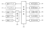
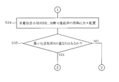
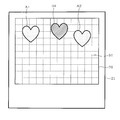
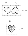
- the perspective view which shows the cutting device by one Embodiment Block diagram showing the electrical configuration of the cutting device The figure which shows the attribute information which the pattern has Flow chart showing the overall processing flow of the cutting data creation program Flow chart showing intra-group placement processing Flowchart showing on-sheet arrangement processing (part 1) Flowchart showing on-sheet arrangement processing (part 2) The figure which shows an example of the display content displayed on a display in a specific process Diagram showing the concept of classification processing Diagram showing the concept of group placement processing The figure which shows the concept at the time of calculating the minimum inclusion rectangle by calculation processing The figure which shows the concept at the time of arranging each pattern in the four corners of the cuttable range The figure which shows an example of the display content displayed on a display by alerting
- the cutting apparatus 10 shown in FIG. 1 cuts the workpiece 100 held by the holding member 90 into a desired shape.
- the cutting device 10 includes a main body cover 11, a platen 12, a carriage 13, and a cutter cartridge 14.
- the platen 12 is provided in the main body cover 11 and has a substantially horizontal plate shape.
- the cutter cartridge 14 is detachably attached to the carriage 13.
- a cutter having a blade portion at the tip is attached in a replaceable manner.
- the main body cover 11 constitutes a casing of the cutting device 10.
- the main body cover 11 has an opening 111 and is configured as a rectangular box as a whole.
- the main body cover 11 covers the entire outside of the platen 12, the carriage 13, and the cutter cartridge 14.
- the opening 111 side with respect to the main body cover 11 is the front side of the cutting device 10.
- a front-rear direction in which the holding member 90 is transferred on the platen 12 is a Y direction
- a left-right direction orthogonal to the Y direction is an X direction.
- the vertical direction perpendicular to the platen 12 is taken as the Z direction.
- the holding member 90 is formed in a rectangular flat plate shape and has an adhesive layer on the surface thereof.
- the holding member 90 holds the workpiece 100 attached to the adhesive layer and is placed on the platen 12.
- a cutable range 91 is set on the holding member 90.
- the cutable range 91 is a rectangular shape that is slightly smaller than the outer shape of the holding member 90.
- the cutting device 10 can cut the workpiece 100 arranged in the cuttable range 91.
- a plurality of ruled lines extending across the X direction and the Y direction are provided at equal intervals.
- the plurality of grids 92 are formed at equal intervals by the plurality of ruled lines.
- the cutting device 10 includes an X-axis movement mechanism, a Y-axis movement mechanism, and a Z-axis movement mechanism.
- the X-axis movement mechanism, the Y-axis movement mechanism, and the Z-axis movement mechanism constitute a cutting mechanism that cuts the workpiece 100 disposed on the holding member 90.
- the X-axis moving mechanism includes the X-axis guide rail 15 shown in FIG. 1 and the X-axis motor 16 shown in FIG.
- the X-axis guide rail 15 is provided in a machine frame (not shown) in the main body cover 11 and extends in the X direction.
- the X-axis motor 16 is provided in the main body cover 11.
- the X-axis moving mechanism moves the carriage 13 in the X direction along the X-axis guide rail 15 by the rotation of the X-axis motor 16.
- the Y-axis moving mechanism includes the drive roller 17 and the pinch roller 18 shown in FIG. 1, and the Y-axis motor 19 shown in FIG.
- the drive roller 17 and the pinch roller 18 are attached to a machine frame (not shown) in the main body cover 11 and extend in the X direction.
- the driving roller 17 and the pinch roller 18 sandwich the both end portions of the holding member 90 set on the platen 12 from above and below.
- the Y-axis motor 19 is provided in the main body cover 11.
- the Y-axis moving mechanism moves the holding member 90 in the Y direction by transmitting the rotational motion of the Y-axis motor 19 to the drive roller 17.
- the Z-axis moving mechanism includes a Z-axis motor 20 shown in FIG.
- the Z-axis motor 20 is provided in the carriage 13.
- the Z-axis moving mechanism moves the cutter cartridge 14 in the vertical direction, that is, in the Z direction by the rotation of the Z-axis motor 20.
- the leading end of the cutter attached to the cutter cartridge 14 bites into the workpiece 100 held by the holding member 90.
- the cutting device 10 moves the carriage 13 in the X direction by the X-axis moving mechanism and moves the workpiece 100 in the Y direction by the Y-axis moving mechanism in a state where the tip of the cutter is bitten into the workpiece 100. By doing so, the workpiece 100 is cut into a desired shape.
- an XY coordinate system is set with the origin O as the left corner of the cutable range 91 of the holding member 90 shown in FIG. 1, and the holding member 90 and the cutter described above are based on the XY coordinate system. Relative movement with the cartridge 14 is performed.
- the cutting device 10 includes a display 21 and various operation switches 22 as shown in FIGS. 1 and 2.
- the display 21 is a color liquid crystal display, for example, and displays a message or the like necessary for the user. The user checks various settings and operating conditions by operating the various operation switches 22.
- the display 21 may be a touch type liquid crystal display having an input function.
- the cutting device 10 includes a control circuit 30 as shown in FIG.
- the control circuit 30 is mainly composed of a microcomputer having a storage area such as a CPU, ROM, RAM, and rewritable flash memory (not shown), and controls the entire cutting apparatus 10.
- the display 21 and various operation switches 22 are connected to the control circuit 30.
- the X-axis motor 16, the Y-axis motor 19, and the Z-axis motor 20 are connected to the control circuit 30 via the drive circuit 23.
- the ROM of the control circuit 30 stores a control program such as a cutting data generation program and an operation program.
- the RAM of the control circuit 30 stores cutting data and the like for driving the motors 16, 19, and 20 to cut the workpiece 100 into a desired shape.
- the cutting device 10 can generate cutting data by executing the cutting data generation program.
- the cutting apparatus 10 can also acquire cutting data generated by another computer via, for example, the Internet or a removable storage medium.
- the control circuit 30 executes the cutting data generation program stored in the ROM by the CPU, thereby enabling the specific processing unit 31, the acquisition processing unit 32, the classification processing unit 33, the generation processing unit 34, the calculation processing unit 35, and the like. Virtually realized by software.
- Each of the processing units 31 to 35 may be realized in hardware as an integrated circuit integrated with the control circuit 30, for example, or may be realized in cooperation with hardware and software.
- the control circuit 30 executes the cutting data generation program when the cutting device 10 is powered on.
- the control circuit 30 first executes specific processing by the operation of the specific processing unit 31 in step S11 of FIG.
- the specifying process is a process for specifying a plurality of patterns to be cut.
- the user operates the various operation switches 22 while viewing information such as patterns displayed on the display 21 and inputs information such as the type and number of patterns to be cut.
- FIG. 8 it is assumed that the user has selected three patterns, for example, a green heart-shaped pattern A1 and a pattern A2, and a yellow heart-shaped pattern B1. In this case, there are two types of patterns: a green heart-shaped pattern and a yellow heart-shaped pattern.
- the display 21 displays a cutable range 91 of the holding member 90 together with, for example, the grid 92.
- the control circuit 30 specifies that the pattern to be cut is the three patterns of the pattern A1, the pattern A2, and the pattern B1.
- the control circuit 30 specifies the pattern to be cut in the order of the pattern selected by the user, and causes the display 21 to display the pattern.
- the control circuit 30 specifies patterns to be cut in the order of patterns A1, B1, and A2, and displays the patterns in the order of patterns A1, B1, and A2. 21 is displayed.
- the control circuit 30 specifies the pattern A1 as the pattern to be cut, and displays the pattern A1 on the display 21. Then, the user operates the various operation switches 22 while viewing the pattern A1 displayed on the display 21 and arranges the pattern A1 at an arbitrary position within the cuttable range 91 displayed on the display 21.
- the control circuit 30 specifies the pattern B1 as a pattern to be cut and displays the pattern B1 on the display 21. Then, the user places the pattern B1 in a vacant space where the pattern A1 is not arranged in the cuttable range 91 displayed on the display 21.
- the patterns A1, A2, and B2 are not aligned, and are arranged in a state where a plurality of patterns having different colors are mixed.
- the specifying process may specify a pattern to be cut by the user selecting cutting data for a single pattern that has already been generated.
- the control circuit 30 can specify the pattern based on the file name attached to the cutting data.
- a pattern to be cut may be specified based on an image captured by the scanner function.
- the acquisition process is a process of acquiring attribute information representing the attributes of the patterns A1, A2, and B1 specified by the specifying process.
- Each pattern A1, A2, B1 has attribute information as shown in FIG. 3, for example.
- the attribute information indicates the attribute of each pattern A1, A2, B1, and is, for example, a color or a shape name.
- the attributes of the patterns A1 and A2 are the color “green” and the shape name “heart”.
- the attributes of the pattern B1 are a color “yellow” and a shape name “heart”.
- the attribute information may be stored in association with each pattern, or may be included in cutting data for cutting the pattern.
- the pattern to be cut may be specified based on the image captured by the scanner function, the color or shape of the pattern may be specified, and the pattern attribute information may be stored in association with the pattern.
- step S13 in FIG. 4 the control circuit 30 determines whether or not the total number of patterns to be cut is two or more.
- the control circuit 30 shifts the processing to step S16.
- the control circuit 30 proceeds to step S14.
- step S ⁇ b> 14 the control circuit 30 executes the classification process by the action of the classification processing unit 33.
- the classification process is a process of classifying each pattern into one or more groups based on the pattern attribute information acquired in the acquisition process.
- the group includes at least one pattern.
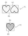
- groups are classified according to the colors of patterns A1, A2, and B1 to be cut. That is, in this case, the control circuit 30 classifies the patterns A1, A2, and B1 into a first group 61 and a second group 62 as shown in FIG.
- the first group 61 includes patterns A1 and A2 having an attribute of color “green”.
- the second group 62 includes a pattern B1 having an attribute of color “yellow”.
- the intra-group arrangement process is a process for optimizing the distance relationship between patterns belonging to the same group by rearranging each pattern at an appropriate position for each group classified by the classification process. Specifically, the process shown in FIG. 5 is performed.
- the variable i is a positive integer of 1 or more.
- step S22 the control circuit 30 determines whether or not the variable i is N or less.
- the control circuit 30 repeats steps S22 to S26 until the variable i exceeds N.
- the control circuit 30 proceeds to step S23 and arranges the i-th group pattern at an optimal position.
- a conventionally used technique such as nesting can be employed.
- the control circuit 30 executes calculation processing by the operation of the calculation processing unit 35 in step S24 of FIG.
- the calculation process calculates an inclusion rectangle that is a rectangle that includes all patterns belonging to the same group.
- the control circuit 30 calculates the minimum inclusion rectangle Ri of each group. “I” of Ri indicates a group number, and the value of the variable i is entered.
- the minimum inclusion rectangle R 1 is the minimum inclusion rectangle of the first group 61
- the minimum inclusion rectangle R 2 is the minimum inclusion rectangle of the second group 62. Note that the minimum inclusion rectangle R is used to collectively indicate the minimum inclusion rectangle of each group.
- the minimum inclusion rectangle R is an aspect of the inclusion rectangle and is included in the concept of the inclusion rectangle.
- the minimum inclusion rectangle R is a rectangle that touches the outer shape of the pattern belonging to the same group.
- the size of the minimum inclusion rectangle R is the minimum size of the workpiece 100 necessary for cutting the pattern arranged in the minimum inclusion rectangle R.
- the minimum inclusion rectangle R1 of the first group 61 is a rectangle in contact with the outer shapes of the patterns A1 and A2, and includes all the patterns A1 and A2 belonging to the color “green”.
- control circuit 30 memorize
- the control circuit 30 executes an on-sheet arrangement process in step S16 of FIG.
- the on-sheet arrangement process is a process for virtually arranging each pattern to be cut within the cuttable range 91.
- “virtually arranging a pattern” represents processing performed in the control circuit 30. In this case, it does not matter whether the result of virtually arranging the pattern is displayed on the display 21 or the like and visualized.
- the control circuit 30 When the on-sheet arrangement process is executed, the control circuit 30 first determines in step S31 shown in FIG. 6 whether or not the sum of the areas of the minimum inclusion rectangle R of each group is equal to or smaller than the area of the cuttable range 91. .
- the area of the cuttable range 91 is stored in advance in the ROM, RAM, or the like of the control circuit 30.
- the control circuit 30 shifts the process to step S32.
- step S33 the control circuit 30 determines whether the total number of groups is 4 or less.
- step S34 the control circuit 30 shifts the processing to step S34 in FIG.
- step S ⁇ b> 34 the control circuit 30 arranges the minimum inclusion rectangle R of each group at each of the four corners of the cuttable range 91, thereby virtually arranging the pattern of each group on the holding member 90. “Arrangement of minimum inclusion rectangle R” means that the patterns are arranged while maintaining the positional relationship between the patterns included in the minimum inclusion rectangle R.
- the control circuit 30 arranges the minimum inclusion rectangle R with reference to the corner of the cuttable range 91. Specifically, the control circuit 30 arranges each minimum inclusion rectangle R so that one corner of the minimum inclusion rectangle R matches the corner of the cuttable range 91. Note that the corners of the minimum inclusion rectangle R and the corners of the cuttable range 91 do not have to be completely matched, and a margin of about several mm may be provided.
- the minimum inclusion rectangle R1 of the first group 61 is arranged at the upper left corner of the cuttable range 91.
- the control circuit 30 matches the upper left corner of the minimum inclusion rectangle R1 with the upper left corner of the cuttable range 91.
- the patterns A1 and A2 belonging to the first group 61 are virtually arranged in the minimum inclusion rectangle R1 arranged at the upper left corner of the cuttable range 91.
- the minimum inclusion rectangle R ⁇ b> 2 of the second group 62 is arranged at the lower right corner of the cuttable range 91.
- the control circuit 30 matches the lower right corner of the minimum inclusion rectangle R2 with the lower right corner of the cuttable range 91.
- the pattern B1 belonging to the second group 62 is virtually arranged in the minimum inclusion rectangle R2 arranged in the lower right corner of the cuttable range 92.
- the control circuit 30 determines whether or not the minimum inclusion rectangles R overlap in step S35 of FIG. When the minimum inclusion rectangles R overlap each other (YES in step S35), the control circuit 30 shifts the processing to step S36 in FIG. On the other hand, when there is no overlap between the minimum inclusion rectangles R (NO in step S35), the control circuit 30 shifts the processing to step S43 in FIG. Then, the control circuit 30 stores “processing success” in step S43, calculates the recommended paper size for each of the groups 61 and 62 in step S44, and then shifts the processing to step S17 in FIG. 4 (return).
- the calculation of the recommended paper size is performed based on the minimum inclusion rectangles R1 and R2 of the groups 61 and 62. For example, when the minimum inclusion rectangle R1 of the first group 61 is larger than the A6 standard paper and smaller than the A5 standard paper, the recommended paper size of the first group 61 is A5. Similarly, for example, when the minimum inclusion rectangle R2 of the second group 62 is larger than the A7 standard paper and smaller than the A6 standard paper, the recommended paper size of the second group 62 is A6.
- step S17 the control circuit 30 determines whether or not the on-sheet arrangement process in step S16 is successful. If the on-sheet arrangement process is unsuccessful (NO in step S17), the control circuit 30 shifts the process to step S20 and notifies the user that the process has failed. In this case, the control circuit 30 displays an error message on the display 21, for example. A specific example of this error message is, for example, “Automatic placement could not be performed and processing will be terminated”.
- the control circuit 30 shifts the process to step S18 and executes the notification process.
- the notification process provides the user with information regarding the arrangement position of each pattern within the cuttable range 91 of the holding member 90, information regarding the recommended paper size corresponding to each group, information regarding the position where each paper is attached to the holding member 90, and the like. This is a notification process.
- Each of the above information is displayed on, for example, the display 21 as shown in FIG.
- the display 21 includes, for example, a graphic P1 indicating the recommended paper size and pasting position of the first group 61, a graphic P2 indicating the recommended paper size and pasting position of the second group 62, and the groups 61 and 62. Character information P3 indicating the recommended paper size is displayed. In this case, the display 21 also displays a frame indicating the cuttable range 91 and a grid 92.
- step S19 the control circuit 30 generates cutting data by the action of the generation processing unit 34.
- the control circuit 30 generates cutting data in which each pattern is arranged so that the minimum inclusion rectangles R of each group do not overlap each other.
- This cutting data is a pattern in which each pattern is automatically arranged by the above-described processing, and includes all the patterns to be cut, in this case, the patterns A1, A2, and B1. Then, the control circuit 30 ends the series of processes (end in FIG. 4).
- control circuit 30 determines that the total number of groups exceeds 4 (NO in step S33 in FIG. 6), or the total number of groups is 4 or less (YES in step S33) and the minimum inclusion rectangle R is set. If there is an overlap (YES in step S35 in FIG. 7), steps S36 to S44 in FIG. 6 are executed.
- steps S36 to S44 in FIG. 6 are executed.
- FIG. 14 it is assumed that six types of patterns are specified.
- the patterns A1, A2, and A3 have the same attribute and belong to the first group 71.
- the patterns B1, B2, and B3 have the same attribute and belong to the second group 72.
- the patterns C1 and C2 have the same attribute and belong to the third group 73.
- the patterns D1 and D2 have the same attribute and belong to the fourth group 74.
- the pattern E1 and the pattern F1 belong to the fifth group 75 and the sixth group 76, respectively.
- the patterns A1 to A3, B1 to B3, C1, C2, D1, D2, F1, and E1 are not aligned, and are arranged in a state where a plurality of colors are mixed.
- the patterns are classified into the same groups by the above-described processing, and the minimum inclusion rectangle R is calculated for each group.
- step S33 the control circuit 30 determines that the total number of groups exceeds 4 in step S33 (NO in step S33).
- the control circuit 30 proceeds to step S36.
- step S36 the control circuit 30 virtually arranges the minimum inclusion rectangles R1 to R6 of the groups 71 to 76 on the cuttable range 91 so that the minimum inclusion rectangles R do not overlap each other. .
- the control circuit 30 transfers a process to step S37.
- step S37 the control circuit 30 determines whether or not all the minimum inclusion rectangles R1 to R6 of the groups 71 to 76 are within the cuttable range 91.
- the control circuit 30 shifts the process to step S32.
- the control circuit 30 memorize
- the control circuit 30 shifts the processing to step S38.
- the control circuit 30 acquires the initial value of the distance L in step S38 of FIG.
- the distance L indicates a target value of the distance between two adjacent patterns belonging to different groups among a plurality of patterns virtually arranged on the holding member 90.
- the initial value of the distance L may be stored in advance by the control circuit 30 or may be determined by a user input.
- the control circuit 30 calculates the expanded inclusion rectangle NR of each group, in this case, the enlarged inclusion rectangles NR1 to NR6, by the operation of the calculation processing unit 35.
- the enlarged inclusion rectangle NR is obtained by enlarging the minimum inclusion rectangle R by a predetermined range as shown in FIGS. 15 and 16.
- the expanded inclusion rectangle NR is an aspect of the inclusion rectangle and is included in the concept of the inclusion rectangle.
- the enlarged inclusion rectangle NR is a rectangle obtained by enlarging the outer periphery of the minimum inclusion rectangle R by L / 2 as shown in FIG. That is, the predetermined range for enlarging the minimum inclusion rectangle R is the distance L. In this case, when the width of the minimum inclusion rectangle is W and the height is H, the width of the enlarged inclusion rectangle is W + L and the height is H + L.
- step S40 the control circuit 30 virtually arranges the enlarged inclusion rectangles NR1 to NR6 of the groups 71 to 76 on the cuttable range 91 so that the enlarged inclusion rectangles NR do not overlap each other.
- “arrangement of enlarged inclusion rectangle NR” means that the patterns are arranged while maintaining the positional relationship between the patterns included in the enlarged inclusion rectangle NR.
- the control circuit 30 When virtually arranging each enlarged inclusion rectangle NR, the control circuit 30 expands the inclusion rectangle along the grid 92 with reference to the upper left corner of the cuttable range 91, for example, as shown in FIG. They are arranged in order from the largest NR area. In this case, the control circuit 30 arranges at least one side of the enlarged inclusion rectangle NR so as to match the ruled line that forms the grid 92. In the present embodiment, the control circuit 30 arranges the expanded inclusion rectangle NR so that one corner of the expanded inclusion rectangle NR matches the corner of the grid 92.
- step S42 the control circuit 30 displays on the display 21 such that the distance L smaller than the current distance L is input again, and prompts the user to input the distance L again. And the control circuit 30 re-acquires the distance L re-input by the user, and performs step S39 and subsequent steps again. Note that the re-acquisition of the distance L in step S42 may automatically decrease the distance L within the control circuit 30, for example, regardless of the user input.
- step S41 when all of the expanded inclusion rectangles NR1 to NR6 of the groups 71 to 76 are within the cuttable range 91 (YES in step S41), the control circuit 30 shifts the processing to step S43 and displays “Successful processing”. Is memorized. In step S44, the control circuit 30 calculates the recommended paper size for each of the groups 71 to 76, and then proceeds to step S17 in FIG. 4 (return).
- step S17 If the on-sheet arrangement process fails (NO in step S17), the control circuit 30 shifts the process to step S20 and causes the display 21 to display the error message described above. On the other hand, if the on-sheet arrangement process is successful (YES in step S17), the control circuit 30 shifts the process to step S18 and executes the notification process. As a result, as shown in FIG. 18, graphics Q1 to Q6 indicating the recommended paper size of each group 71 to 76 and the pasting position of the paper, and character information Q7 indicating the recommended paper size of each group 71 to 76. Is displayed on the display 21.
- the recommended paper size is calculated based on the expanded inclusion rectangles NR1 to NR6 of the groups 71 to 76.
- the control circuit 30 causes the display 21 to display enlarged inclusion rectangles NR1 to NR6 of the groups 71 to 76 and figures Q1 to Q6 indicating the positions thereof.
- the recommended paper size is represented by the number of vertical and horizontal grids 92 in the case of graphics Q1 to Q6, and the height H [mm] ⁇ in the case of character information Q7. It is represented by a numerical value such as a width W [mm].
- a number is assigned to each of the vertical and horizontal ruled lines constituting the grid 92, and the number of the ruled line corresponding to the grid 92 at the recommended paper pasting position is displayed on the display 21. May be. Further, for example, the following may be performed. That is, all the squares 92 are numbered.
- the number may be displayed on the display 21.
- control circuit 30 produces
- control circuit 30 generates cutting data after each pattern is automatically arranged.
- This cutting data includes all the patterns to be cut, in this case, the patterns A1 to A3, B1 to B3, C1, C2, D1, D2, E1, and F1.
- two adjacent patterns among patterns belonging to different groups are arranged at least a distance L apart.
- the pattern A3 is used as a reference.
- a distance between another pattern A2 that belongs to the same first group 71 as the reference pattern A3 and is adjacent to the reference pattern A3, and the reference pattern A3 is a distance X1.
- a distance between another pattern B3 belonging to a group different from the reference pattern A3, for example, the second group 72 and adjacent to the reference pattern A3, and the reference pattern A3 is X2.
- the control circuit 30 arranges each pattern so that the distance X2 is larger than the distance X1.
- the distance X1 and the distance X2 are distances at which the distance between the reference pattern and another adjacent pattern is the shortest.
- each expanded inclusion rectangle NR are not necessarily the corners of the grids 92 as shown in FIGS. There is no need to match the part. In this case, the enlarged inclusion rectangles NR may be in contact with each other so as not to overlap each other.
- control circuit 30 ends a series of processing (end in FIG. 4).
- the cutting apparatus 10 can cut all the patterns to be cut by operating the cutting mechanism based on the cutting data generated in step S19.
- each pattern is classified into a group composed of patterns having the same attribute. The Then, cutting data in which each pattern is virtually arranged for each group is generated. According to this, each pattern is arranged together for each attribute. Therefore, for example, even when a plurality of patterns having different attributes such as color are to be cut, they are arranged in a state where a plurality of types of patterns having different attributes are mixed, that is, in a state where patterns of each attribute are mixed. There is nothing to do. Therefore, the user should arrange
- the control circuit 30 determines the distance between adjacent patterns belonging to different groups, for example, the distance between adjacent patterns in the same group, for example, the distance X1 between the patterns A3 and A2.
- the cutting data in which each pattern is arranged is generated so that the distance X2 between the pattern A3 and the pattern B3 becomes larger. According to this, waste of the workpiece 100 can be reduced by reducing the distance between patterns belonging to the same group. Further, by increasing the distance between the groups, the workpiece 100 corresponding to each group can be easily placed on the holding member 90.
- control circuit 30 calculates an inclusion rectangle that is a rectangle that includes all patterns belonging to the same group, for example, a minimum inclusion rectangle R or an enlarged inclusion rectangle NR. Then, the control circuit 30 generates cutting data in which each pattern is arranged so that the minimum inclusion rectangle R or the enlarged inclusion rectangle NR of each group does not overlap each other. According to this, by calculating the size and position of the workpiece 100 to be placed on the holding member 90 based on the minimum inclusion rectangle R or the enlarged inclusion rectangle NR, the workpiece to be cut arranged on the holding member 90. The objects 100 do not overlap each other. Therefore, it becomes easy to arrange the workpiece 100 with respect to the holding member 90.
- control circuit 30 generates cutting data in which each pattern is arranged so that the enlarged inclusion rectangles NR do not overlap each other. That is, the control circuit 30 generates cutting data in which patterns belonging to other groups are arranged outside a range that is enlarged by a predetermined distance L from the minimum inclusion rectangle R. According to this, since the distance between groups can be ensured large, it becomes easier to arrange the workpiece 100.
- the predetermined distance for enlarging the minimum inclusion rectangle R may be the same distance in the vertical and horizontal directions of the minimum inclusion rectangle R, or may be different distances in each direction.
- the control circuit 30 arranges each pattern by aligning the corners of the minimum inclusion rectangle R or the enlarged inclusion rectangle NR for each group with respect to each corner of the cuttable range 91. Generated cutting data. According to this, when the total number of groups is 4 or less, the user arranges the workpiece 100 on the holding member 90 so that the corners of the workpiece 100 and the corners of the cutable range 91 are aligned. Therefore, the arrangement of the workpiece 100 is further facilitated.
- the holding member 90 has grids 92 arranged at a predetermined interval.
- the control circuit 30 NR overlaps with each other, cutting data in which each pattern is arranged with the corner of the minimum inclusion rectangle R or the enlarged inclusion rectangle NR aligned with the corner of the grid 92 is generated.
- the user can cut the workpiece 100 so that the corner of the workpiece 100 and the corner of the cutable range 91 or the corner of the workpiece 100 and the corner of the grid 92 match each other. Since it can arrange
- the cutting device 10 displays on the display 21 the size of the workpiece 100 determined by the minimum inclusion rectangle N or the enlarged inclusion rectangle NR and the position where the workpiece 100 is to be disposed with respect to the holding member 90. According to this, the user can easily confirm the size of the workpiece 100 and the position where the workpiece 100 should be disposed with respect to the holding member 90.
- the present invention is not limited to the above-described embodiments, and various expansions and modifications can be made without departing from the scope of the present invention.
- the number of patterns is not limited to the number of groups.
- the processing of the above-described embodiment can be applied even when there is one group as a result of the classification of the specified pattern. Can be applied.
- the above-described cutting data creation program is recorded not only on the control circuit 30 of the cutting apparatus 10 but also on various recording media such as a USB memory, a CD-ROM, a flexible disk, a DVD, and a memory card. In this case, the program recorded on the recording medium is read and executed by the computer of various data processing apparatuses, and the same operations and effects as the above-described embodiment are obtained.
- Cutting Device 31 Specific Processing Unit 32 Acquisition Processing Unit 33 Classification Processing Unit 34 Generation Processing Unit 35 Calculation Processing Unit 90 Holding Member 91 Cutable Range 92 Grid
Landscapes
- Engineering & Computer Science (AREA)
- Life Sciences & Earth Sciences (AREA)
- Forests & Forestry (AREA)
- Mechanical Engineering (AREA)
- General Engineering & Computer Science (AREA)
- Control Of Cutting Processes (AREA)
Abstract
切断対象となる模様に属性が異なる複数の模様が混在している場合に、ユーザが保持部材に対する各被切断物の配置を容易に行うことができるようにする。切断装置は、切断データに基づいて保持部材上に配置された被切断物を切断する切断機構と、切断対象となる複数の模様を特定する特定処理部と、特定処理部で特定した模様の属性を表す属性情報を取得する取得処理部と、取得処理部で取得した属性情報に基づいて各模様を2以上のグループに分類する分類処理部と、保持部材によって定まる切断可能範囲内において、分類処理部で分類されたグループ毎に模様を配置した切断データを生成する生成処理部と、を備える。
Description
本発明は、シート状の被切断物を切断する切断装置、及びその切断装置に用いられる切断データを生成する切断データ生成プログラムに関する。
従来、被切断物であるシート状の紙等を、ユーザが所望する模様形状に自動的に切断する切断装置が知られている。切断装置は保持部材を備えており、被切断物は保持部材上に配置される。そして、切断装置は、ユーザが所望する模様形状から切断データを生成し、その切断データに基づいて保持部材上の被切断物を切断する。
このような切断装置には、次のような機能を備えたものがある。その機能とは、複数の模様を一度の切断作業で切断する際に、各模様を保持部材に対する適切な位置に自動配置した切断データを生成する機能である。この場合、保持部材上の適切な位置とは、各模様間の距離が極力小さくなるような位置である。
しかし、色等の属性が異なる複数の模様を切断対象とした場合に上記の自動配置を行うと、属性の異なる複数種類の模様が混在した状態で、つまり各属性の模様が入り混じった状態で配置されることになる。この場合、ユーザは、各模様が切断される位置に合わせて、その模様の属性に対応する被切断物を保持部材上に配置しなければならず、その作業は煩雑なものであった。
本発明は上記事情に鑑みてなされたものであり、その目的は、切断対象となる模様に属性が異なる複数の模様が混在している場合に、ユーザが保持部材に対する各被切断物の配置を容易に行うことができるようにする切断装置、及び切断データ生成プログラムを提供することである。
上記の目的を達成するために、請求項1の切断装置は、切断データに基づいて保持部材上に配置された被切断物を切断する切断機構と、切断対象となる複数の模様を特定する特定処理部と、前記特定処理部で特定した前記模様の属性を表す属性情報を取得する取得処理部と、前記取得処理部で取得した前記属性情報に基づいて各前記模様を2以上のグループに分類する分類処理部と、前記保持部材によって定まる切断可能範囲内において、前記分類処理部で分類された前記グループ毎に前記模様を配置した前記切断データを生成する生成処理部と、を備える。
また、請求項9の切断データ生成用プログラムは、保持部材上に載置された被切断物を切断する切断機構を備えた切断装置で用いられる切断データを生成するコンピュータによって実行される。そして、前記切断データ生成用プログラムは、前記コンピュータに、切断対象となる複数の模様を特定する特定処理と、前記特定処理で特定した前記模様の属性を表す属性情報を取得する取得処理と、前記取得処理で取得した前記属性情報に基づいて各前記模様を2以上のグループに分類する分類処理と、前記保持部材によって定まる切断可能範囲内において、前記分類処理で分類された前記グループ毎に各前記模様を配置した前記切断データを生成する生成処理と、を実行させることができる。
請求項1の切断装置によれば、切断対象となる模様に属性が異なる複数の模様が混在している場合、各模様は、分類処理部によって、同一の属性を有する模様で構成されたグループに分類される。そして、生成処理部によって、グループ毎に各模様を配置した切断データが生成される。これによれば、各模様は、その属性毎にまとまって配置される。したがって、属性が異なる複数の模様を切断対象とした場合であっても、属性の異なる複数種類の模様が混在した状態で、つまり各属性の模様が入り混じった状態で配置されることが無くなる。そのため、ユーザは、グループを構成する模様の属性に合わせて被切断物を配置すれば良く、その結果、保持部材に対する各被切断物の配置を容易に行うことができる。
請求項9に記載の切断データ生成プログラムは、請求項1に記載の切断装置によって生成される切断データを生成するためのものである。請求項9に記載の切断データ生成プログラムを、例えばパソコンや既存の切断装置で実行することにより、そのパソコンや既存の切断装置で、上述した切断データを生成することができる。
以下、一実施形態による切断装置及び切断データ生成プログラムについて、図面を参照しながら説明する。
図1に示す切断装置10は、保持部材90に保持された被切断物100を、所望の形状に切断するものである。切断装置10は、本体カバー11、プラテン12、キャリッジ13、及びカッタカートリッジ14を備えている。プラテン12は、本体カバー11内に設けられ、略水平な板状に構成されている。カッタカートリッジ14は、キャリッジ13に着脱可能に取り付けられている。また、カッタカートリッジ14には、詳細は図示しないが、先端に刃部が設けられたカッタが交換可能に取り付けられている。
図1に示す切断装置10は、保持部材90に保持された被切断物100を、所望の形状に切断するものである。切断装置10は、本体カバー11、プラテン12、キャリッジ13、及びカッタカートリッジ14を備えている。プラテン12は、本体カバー11内に設けられ、略水平な板状に構成されている。カッタカートリッジ14は、キャリッジ13に着脱可能に取り付けられている。また、カッタカートリッジ14には、詳細は図示しないが、先端に刃部が設けられたカッタが交換可能に取り付けられている。
本体カバー11は、切断装置10の筐体を構成するものである。本体カバー11は、開口部111を有し、全体として矩形の箱状に構成されている。本体カバー11は、プラテン12、キャリッジ13、及びカッタカートリッジ14の外側全体を覆っている。以下の説明では、本体カバー11に対して開口部111側を、切断装置10の前側とする。また、プラテン12上において保持部材90が移送される前後方向をY方向とし、Y方向と直交する左右方向をX方向とする。そして、プラテン12と直交する上下方向をZ方向とする。
保持部材90は、矩形の平板状に形成されており、その表面に粘着層を有する。保持部材90は、粘着層に貼り付けられた被切断物100を保持し、プラテン12上に載置される。保持部材90上には、切断可能範囲91が設定されている。切断可能範囲91は、保持部材90の外形よりも一回り小さい矩形状である。切断装置10は、切断可能範囲91内に配置された被切断物100を切断することができる。切断可能範囲91内には、X方向及びY方向に交差して延びる複数の罫線が等間隔に設けられている。そして、この複数の罫線によって複数のマス目92が等間隔に形成されている。
切断装置10は、X軸移動機構、Y軸移動機構、及びZ軸移動機構を備えている。X軸移動機構、Y軸移動機構、及びZ軸移動機構は、保持部材90上に配置された被切断物100を切断する切断機構を構成する。X軸移動機構は、図1に示すX軸ガイドレール15と、図2に示すX軸モータ16等を含んで構成されている。X軸ガイドレール15は、本体カバー11内の図示しない機枠に設けられ、X方向へ延びている。X軸モータ16は、本体カバー11内に設けられている。X軸移動機構は、X軸モータ16の回転により、キャリッジ13をX軸ガイドレール15に沿ってX方向へ移動させる。
Y軸移動機構は、図1に示す駆動ローラ17及びピンチローラ18と、図2に示すY軸モータ19を含んで構成されている。駆動ローラ17及びピンチローラ18は、本体カバー11内の図示しない機枠に取り付けられ、X方向に延びている。駆動ローラ17及びピンチローラ18は、プラテン12上にセットされた保持部材90の両端部分を上下方向から挟む。Y軸モータ19は、本体カバー11内に設けられている。Y軸移動機構は、Y軸モータ19の回転運動を駆動ローラ17に伝達することで、保持部材90をY方向へ移動させる。
Z軸移動機構は、図2に示すZ軸モータ20を含んで構成されている。Z軸モータ20は、キャリッジ13内に設けられている。Z軸移動機構は、Z軸モータ20の回転により、カッタカートリッジ14を上下方向つまりZ方向へ移動させる。
この構成において、Z軸移動機構によってカッタカートリッジ14が下方へ移動されると、カッタカートリッジ14に取り付けられたカッタの先端部は、保持部材90に保持されている被切断物100に食い込む。切断装置10は、カッタの先端部を被切断物100に食い込ませた状態で、X軸移動機構によってキャリッジ13をX方向へ移動させるとともに、Y軸移動機構によって被切断物100をY方向へ移動させることで、被切断物100を所望の形状に切断する。
なお、切断装置10では、例えば図1に示す保持部材90の切断可能範囲91の左角部を原点OとしたXY座標系が設定され、そのXY座標系に基づいて上記した保持部材90とカッタカートリッジ14との相対移動が行われる。
切断装置10は、図1及び図2に示すように、ディスプレイ21と、各種操作スイッチ22と、を備えている。ディスプレイ21は、例えばカラー液晶ディスプレイであり、ユーザに対して必要なメッセージ等の表示を行う。ユーザは、各種操作スイッチ22を操作することによって、各種の設定や動作状況の確認を行う。なお、ディスプレイ21は、入力機能を有するタッチ式液晶ディスプレイであってもよい。
切断装置10は、図2に示すように、制御回路30を備えている。制御回路30は、例えば図示しないCPU、ROM、RAM、及び書き換え可能なフラッシュメモリ等の記憶領域を有するマイクロコンピュータを主体に構成されており、切断装置10の全体を制御する。ディスプレイ21及び各種操作スイッチ22は、制御回路30に接続されている。また、X軸モータ16、Y軸モータ19、及びZ軸モータ20は、駆動回路23を介して制御回路30に接続されている。
制御回路30のROMは、切断データ生成プログラムや動作プログラム等の制御プログラムを記憶している。制御回路30のRAMは、各モータ16、19、20を駆動させて被切断物100を所望の形状に切断するための切断データ等を記憶する。切断装置10は、切断データ生成プログラムの実行によって自ら切断データを生成することができる。また、切断装置10は、例えばインターネットや着脱可能な記憶媒体を介して、他のコンピュータで生成された切断データを取得することもできる。
制御回路30は、ROMに記憶されている切断データ生成プログラムをCPUで実行することにより、特定処理部31、取得処理部32、分類処理部33、生成処理部34、及び算出処理部35等を、ソフトウェアによって仮想的に実現する。なお、これら各処理部31~35は、例えば制御回路30と一体の集積回路としてハードウェア的に実現してもよいし、ハードウェアとソフトウェアとの協働によって実現してもよい。
次に、制御回路30で行われる制御内容について説明する。なお、以下の説明において、各処理部31~35が行う処理は、全て制御回路30が行う処理として説明する。図4~図7のフローチャートは、制御回路30が実行する切断データ作成プログラムの流れを示している。また、図8等において模様に付されたハッチングは、模様の色彩を意味する。すなわち、模様のハッチングが異なることは、模様の色彩が異なることを意味する。
制御回路30は、切断装置10の電源がオンされることにより、切断データ生成プログラムを実行する。制御回路30は、切断データ生成プログラムを実行すると、まず、図4のステップS11において、特定処理部31の作用により特定処理を実行する。特定処理は、切断対象となる複数の模様を特定する処理である。例えばユーザは、ディスプレイ21に表示される模様等の情報を見ながら各種操作スイッチ22を操作して、切断対象にする模様の種類や数等の情報を入力する。ここでは、図8に示すように、ユーザが、例えば緑色のハート型の模様A1、模様A2と、黄色のハート型の模様B1との3つの模様を選択した場合を想定する。この場合、模様の種類は、緑色のハート型の模様と黄色のハート型の模様との2種類である。
図8に示すように、ディスプレイ21には、例えばマス目92と共に保持部材90の切断可能範囲91が表示されている。ユーザは、例えば切断対象として模様A1と模様A2と模様B1とを選択し、ディスプレイ21に表示された切断可能範囲91内に配置する。これにより制御回路30は、切断対象となる模様が、模様A1と模様A2と模様B1との3つの模様であることを特定する。この場合、制御回路30は、ユーザが選択した模様の順に、切断対象となる模様を特定し、その模様をディスプレイ21に表示させる。例えばユーザが、模様A1、B1、A2の順に選択した場合、制御回路30は、模様A1、B1、A2の順に切断対象となる模様を特定し、模様A1、B1、A2の順に各模様をディスプレイ21に表示させる。
具体的には、ユーザが、まず、模様A1を選択すると、制御回路30は、切断対象となる模様として模様A1を特定し、その模様A1をディスプレイ21に表示させる。そしてユーザは、ディスプレイ21に表示された模様A1を見ながら、各種操作スイッチ22を操作して、その模様A1をディスプレイ21に表示された切断可能範囲91内の任意の位置に配置する。次に、ユーザが、模様B1を選択すると、制御回路30は、切断対象となる模様として模様B1を特定し、その模様B1をディスプレイ21に表示させる。そしてユーザは、その模様B1を、ディスプレイ21に表示された切断可能範囲91内において模様A1が配置されていない空いたスペースに配置する。模様A2についても、同様である。この場合、各模様A1、A2、B2は、整列しておらず、また、色が異なる複数の模様が混在した状態で配置されている。
なお、特定処理は、既に生成されている模様単体の切断データをユーザが選択することにより、切断対象となる模様を特定するようにしてもよい。この場合、制御回路30は、切断データに付されたファイル名等に基づいて、その模様を特定することができる。また、切断装置10がスキャナ機能を備えている場合には、スキャナ機能によって取り込んだ画像に基づいて、切断対象となる模様を特定するようにしてもよい。
次に、制御回路30は、図4のステップS12において、取得処理部32の作用により取得処理を実行する。取得処理は、特定処理で特定した模様A1、A2、B1の属性を表す属性情報を取得する処理である。各模様A1、A2、B1は、例えば図3に示すように、属性情報を有している。属性情報は、各模様A1、A2、B1の属性を示すもので、例えば色や形状名等である。本実施形態の場合、模様A1、A2の属性は、色彩「緑」、形状名「ハート」である。模様B1の属性は、色彩「黄」、形状名「ハート」である。
なお、これら属性情報は、模様毎に関連付けて記憶されていてもよいし、その模様を切断する切断データに含まれていてもよい。また、スキャナ機能によって取り込んだ画像に基づいて、切断対象となる模様を特定するとともに、その模様の色彩や形状などを特定し、その模様の属性情報としてその模様に関連付けて記憶してもよい。
次に、制御回路30は、図4のステップS13において、切断対象となる模様の総数が2個以上であるか否かを判断する。切断対象となる模様の総数が1個である場合(ステップS13でNO)、制御回路30は、ステップS16へ処理を移行する。一方、切断対象となる模様の総数が2個以上である場合(ステップS13でYES)、制御回路30は、ステップS14へ処理を移行する。制御回路30は、ステップS14において、分類処理部33の作用により分類処理を実行する。分類処理は、取得処理で取得した模様の属性情報に基づいて、各模様を1以上のグループに分類する処理である。グループは、少なくとも1つの模様を含む。
例えば本実施形態では、切断対象となる模様A1、A2、B1の色彩によってグループを分類する。すなわち、この場合、制御回路30は、図9に示すように、各模様A1、A2、B1を、第1グループ61と、第2グループ62と、に分類する。第1グループ61は、色彩「緑」の属性を有する模様A1、A2で構成されている。第2グループ62は、色彩「黄」の属性を有する模様B1で構成されている。
次に、制御回路30は、図4のステップS15において、グループ内配置処理を実行する。グループ内配置処理は、分類処理で分類したグループ毎に、各模様を適切な位置に再配置することで、同一グループに属する各模様の距離関係を最適化する処理である。具体的には、図5に示す処理が行われる。制御回路30は、グループ内配置処理を実行すると、図5のステップS21において、まず初期設定として変数i=1、N=グループ総数、を設定する。例えば、上述したように切断対象を模様A1、A2、B1とする場合、グループ総数は2であるため、N=2となる。また、変数iは、1以上の正の整数である。
次に、制御回路30は、ステップS22において、変数iがN以下であるか否かを判断する。制御回路30は、変数iがNを超えるまで、ステップS22~S26を繰り返す。変数iがN以下である場合(ステップS22でYES)、制御回路30は、ステップS23へ移行し、第iグループの模様を最適な位置に配置する。この模様の配置の最適化は、例えば従来から用いられているネスティング等の手法を採用することができる。
制御回路30は、例えば図10に示すように、各グループについて、各模様を回転等しながら、各模様間の距離を切断装置10の切断可能な範囲で最小化する。例えば変数i=1の場合、制御回路30は、図10に示すように、第1グループ61に属する模様A1、A2の配置を最適化する。同様に、変数i=2の場合、制御回路30は、第2グループ62に属する模様B1の配置を最適化する。
例えば本実施形態の場合、ステップS21において、初期設定として、i=1、N=2が設定される。この場合、ステップS22においてiが2以下であるため(ステップS22でYES)、制御回路30は、ステップS23において、第1グループ61の各模様A1、A2を配置する。具体的には、模様A1,A2の距離が、切断装置10の切断可能な範囲で最小化した位置関係となるように各模様を配置する。そして、制御回路30は、ステップS24において第1グループ61の最小包含矩形R1を算出した後、ステップS25において第1グループ61の配置後の模様A1、A2を記憶する。具体的には、他の模様との位置関係と関連付けて各模様を記憶する。そして、制御回路30は、ステップS26において、iに1を加算してi=2にする。
次も、ステップS22においてiが2以下であるため(ステップS22でYES)、制御回路30は、ステップS23において、第2グループ62の模様B1を配置する。そして、制御回路30は、ステップS24において第2グループ62の最小包含矩形R2を算出した後、ステップS25において第2グループ62の配置後の模様B1を記憶する。そして、制御回路30は、ステップS26において、iに1を加算してi=3にする。すると、ステップS22においてiが2を超えたため(ステップS22でNO)、制御回路30は、グループ内配置処理を終了する(リターン)。
制御回路30は、図5のステップS24において、算出処理部35の作用により算出処理を実行する。算出処理は、同一のグループに属する模様を全て包含する矩形である包含矩形を算出する。本実施形態において、制御回路30は、各グループの最小包含矩形Riを算出する。Riの「i」は、グループの番号を示すもので、変数iの値が入る。例えば、最小包含矩形R1は、第1グループ61の最小包含矩形であり、最小包含矩形R2は、第2グループ62の最小包含矩形である。なお、各グループの最小包含矩形を総称して示す場合は、最小包含矩形Rとする。
最小包含矩形Rは、包含矩形の一態様であり、包含矩形の概念に含まれる。最小包含矩形Rは、同一のグループに属する模様の外形に接する矩形である。最小包含矩形Rのサイズは、当該最小包含矩形R内に配置された模様を切断するために最低限必要な被切断物100のサイズとなる。図11に示すように、例えば第1グループ61の最小包含矩形R1は、模様A1、A2の外形に接する矩形であり、色彩「緑」に属する模様A1、A2を全て含んでいる。
そして、制御回路30は、図5のステップS25において、各グループ61、62の配置後の模様を記憶し、その後、ステップS26で変数iに1を加算する。そして、ステップS22~S26を繰り返し、全てのグループについてステップS22~S26の処理を実行した後、グループ内配置処理を終了する(リターン)。
次に、制御回路30は、図4のステップS16において、シート上配置処理を実行する。シート上配置処理は、切断対象となる各模様を、切断可能範囲91内に仮想的に配置する処理である。なお、本実施形態の説明において、「模様を仮想的に配置」とは、制御回路30内で行われる処理を表現するものである。この場合、模様を仮想的に配置した結果がディスプレイ21等に表示されて可視化されているか否かは問わない。
制御回路30は、シート上配置処理を実行すると、まず図6に示すステップS31において、各グループの最小包含矩形Rの面積の総和が、切断可能範囲91の面積以下であるか否かを判断する。切断可能範囲91の面積は、制御回路30のROM、RAM等に予め記憶されている。各グループの最小包含矩形Rの総面積が切断可能範囲91の面積を超えている場合、切断可能範囲91の内側に全ての模様を配置することは物理的に不可能である。したがって、各グループの最小包含矩形Rの総面積が切断可能範囲91の面積を超えた場合(ステップS31でNO)、制御回路30は、ステップS32へ処理を移行する。そして、制御回路30は、ステップS32において「処理失敗」を記憶し、図4のステップS17へ処理を移行する(リターン)。
一方、各グループの最小包含矩形Rの総面積が切断可能範囲91の面積以下である場合(図6のステップS31でYES)、制御回路30は、ステップS33へ処理を移行する。ステップS33において、制御回路30は、グループの総数が4以下であるか否かを判断する。グループの総数が4以下である場合(ステップS33でYES)、制御回路30は、図7のステップS34へ処理を移行する。制御回路30は、ステップS34において、各グループの最小包含矩形Rを、切断可能範囲91の四隅に夫々配置し、これにより、各グループの模様を保持部材90上に仮想的に配置する。「最小包含矩形Rを配置」とは、最小包含矩形R内に含まれる各模様の相互間の位置関係を維持したまま各模様を配置することを意味する。
この場合、制御回路30は、切断可能範囲91の角部を基準にして、最小包含矩形Rを配置する。具体的には、制御回路30は、最小包含矩形Rの1の角部を切断可能範囲91の角部に合わせるようにして、各最小包含矩形Rを配置する。なお、最小包含矩形Rの角部と切断可能範囲91の角部とは、完全に一致させる必要は無く、数mm程度の余白を設けてもよい。
本実施形態の場合、例えば図12に示すように、第1グループ61の最小包含矩形R1は、切断可能範囲91の左上隅部に配置される。その際、制御回路30は、切断可能範囲91の左上の角部に、最小包含矩形R1の左上の角部を一致させる。これにより、第1グループ61に属する模様A1、A2は、切断可能範囲91の左上隅部に配置された最小包含矩形R1内に仮想的に配置される。また、第2グループ62の最小包含矩形R2は、切断可能範囲91の右下隅部に配置される。その際、制御回路30は、切断可能範囲91の右下の角部に、最小包含矩形R2の右下の角部を一致させる。これにより、第2グループ62に属する模様B1は、切断可能範囲92の右下隅部に配置された最小包含矩形R2内に仮想的に配置される。
その後、制御回路30は、図7のステップS35において、各最小包含矩形Rの重なりが有るか否かを判断する。各最小包含矩形Rが互いに重なる場合(ステップS35でYES)、制御回路30は、図6のステップS36へ処理を移行する。一方、各最小包含矩形Rに重なりが無い場合(ステップS35でNO)、制御回路30は、図6のステップS43へ処理を移行する。そして、制御回路30は、ステップS43において「処理成功」を記憶し、ステップS44で各グループ61、62に対する推奨用紙サイズを算出した後、図4のステップS17へ処理を移行する(リターン)。
推奨用紙サイズの算出は、各グループ61、62の最小包含矩形R1、R2に基づいて行われる。例えば第1グループ61の最小包含矩形R1が、A6規格の紙よりも大きく、かつA5規格の紙よりは小さい場合、第1グループ61の推奨用紙サイズはA5となる。同様に、例えば第2グループ62の最小包含矩形R2が、A7規格の紙よりも大きく、かつA6規格の紙よりは小さい場合、第2グループ62の推奨用紙サイズはA6となる。
制御回路30は、ステップS17において、ステップS16のシート上配置処理が成功したか否かを判断する。シート上配置処理が失敗である場合(ステップS17でNO)、制御回路30は、ステップS20へ処理を移行し、処理が失敗した旨をユーザに報知する。この場合、制御回路30は、例えばディスプレイ21にエラーメッセージを表示する。このエラーメッセージの具体例としては、例えば「自動配置できませんでしたので、処理を終了します」等である。
一方、シート上配置処理が成功した場合(ステップS17でYES)、制御回路30は、ステップS18へ処理を移行し、報知処理を実行する。報知処理は、保持部材90の切断可能範囲91内における各模様の配置位置に関する情報、各グループに対応した推奨用紙サイズに関する情報、及び保持部材90に対する各用紙の貼り付け位置に関する情報等をユーザに報知する処理である。上記の各情報は、図13に示すように、例えばディスプレイ21に表示される。ディスプレイ21には、例えば第1グループ61の推奨用紙のサイズと貼り付け位置を示す図形P1と、第2グループ62の推奨用紙のサイズと貼り付け位置を示す図形P2と、各グループ61、62の推奨用紙のサイズを示す文字情報P3と、が表示される。この場合、ディスプレイ21には、切断可能範囲91を示す枠やマス目92も表示される。
その後、制御回路30は、ステップS19において、生成処理部34の作用によって、切断データを生成する。このようにして、制御回路30は、各グループの最小包含矩形Rが相互に重ならないようにして各模様を配置した切断データを生成する。この切断データは、上述の処理によって各模様を自動配置したもので、切断対象となる模様、この場合、模様A1、A2、B1を全て含んだものである。そして、制御回路30は、一連の処理を終了する(図4でエンド)。
また、制御回路30は、グループの総数が4を超えている場合(図6のステップS33でNO)、又はグループの総数が4以下であって(ステップS33でYES)かつ各最小包含矩形Rに重なりが有る場合(図7のステップS35でYES)、図6のステップS36~S44を実行する。ここでは、例えば図14に示すように、6種類の模様が特定された場合を想定する。
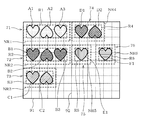
図14に示す各模様のうち、模様A1、A2、A3は、同一の属性を有し、第1グループ71に属する。模様B1、B2、B3は、同一の属性を有し、第2グループ72に属する。模様C1、C2は、同一の属性を有し、第3グループ73に属する。模様D1、D2は、同一の属性を有し、第4グループ74に属する。模様E1及び模様F1は、それぞれ第5グループ75、第6グループ76に属する。この場合、各模様A1~A3、B1~B3、C1、C2、D1、D2、F1、E1は、整列しておらず、また、複数の色が混在した状態で配置されている。各模様は、上述した処理により、図15に示すように、同一のグループ毎に分類され、各グループについて最小包含矩形Rが算出される。
制御回路30は、ステップS33においてグループの総数が4を超えていると判断すると(ステップS33でNO)、ステップS36へ処理を移行する。制御回路30は、ステップS36において、各グループ71~76の各最小包含矩形R1~R6を、切断可能範囲91上に、各最小包含矩形Rが相互に重ならないように詰めて仮想的に配置する。そして、制御回路30は、ステップS37へ処理を移行する。
次に、制御回路30は、ステップS37において、各グループ71~76の最小包含矩形R1~R6が、全て切断可能範囲91内に収まったか否かを判断する。各グループ71~76の最小包含矩形R1~R6が、全て切断可能範囲91内に収まっていない場合(ステップS37でNO)、制御回路30は、ステップS32へ処理を移行する。そして、制御回路30は、ステップS32において「処理失敗」を記憶し、図4のステップS17へ処理を移行する(リターン)。一方、各グループ71~76の最小包含矩形R1~R6が、全て切断可能範囲91内に収まっている場合(ステップS37でYES)、制御回路30は、ステップS38へ処理を移行する。
制御回路30は、図6のステップS38において、距離Lの初期値を取得する。距離Lは、保持部材90上に仮想的に配置される複数の模様のうち、相互に異なるグループに属し、かつ隣接する2つの模様間の距離の目標値を示すものである。距離Lの初期値は、予め制御回路30が記憶しておいてもよいし、ユーザの入力によって決定してもよい。
次に、制御回路30は、ステップS39において、算出処理部35の作用により、各グループの拡大包含矩形NR、この場合、拡大包含矩形NR1~NR6を算出する。拡大包含矩形NRは、図15及び図16に示すように、最小包含矩形Rを所定範囲拡大したものである。拡大包含矩形NRは、包含矩形の一態様であり、包含矩形の概念に含まれる。本実施形態の場合、拡大包含矩形NRは、図16に示すように、最小包含矩形Rの外周をL/2ずつ拡大した矩形である。すなわち、最小包含矩形Rを拡大する所定範囲は、距離Lである。この場合、最小包含矩形の幅をW、高さをHとすると、拡大包含矩形の幅はW+L、高さはH+Lになる。
次に、制御回路30は、ステップS40において、各グループ71~76の各拡大包含矩形NR1~NR6を、切断可能範囲91上に、各拡大包含矩形NRが相互に重ならないように仮想的に配置する。この場合、「拡大包含矩形NRを配置」とは、拡大包含矩形NR内に含まれる各模様の相互間の位置関係を維持したまま各模様を配置することを意味する。
各拡大包含矩形NRを仮想的に配置する際、制御回路30は、例えば図17に示すように、切断可能範囲91の左上の角部を基準にして、マス目92に沿って、拡大包含矩形NRの面積が大きいものから順に詰めて配置する。この場合、制御回路30は、拡大包含矩形NRの少なくとも一辺を、マス目92を構成する罫線に合わせて配置する。本実施形態では、制御回路30は、拡大包含矩形NRの1の角部を、マス目92の角部に合わせるようにして、拡大包含矩形NRを配置する。なお、拡大包含矩形NRの角部と切断可能範囲91の角部と、及び拡大包含矩形NRの角部とマス目92の角部とは、完全に一致させる必要は無く、数mm程度の余白を設けてもよい。
次に、制御回路30は、図6のステップS41において、各グループ71~76の拡大包含矩形NR1~NR6が、全て切断可能範囲91内に収まったか否かを判断する。各グループ71~76の拡大包含矩形NR1~NR6が、全て切断可能範囲91内に収まっていない場合(ステップS41でNO)、制御回路30は、ステップS42へ処理を移行する。制御回路30は、ステップS42において、例えば現在の距離Lよりも小さい距離Lを再入力するようディスプレイ21に表示し、ユーザに距離Lの再入力を促す。そして、制御回路30は、ユーザによって再入力された距離Lを再取得し、ステップS39以降を再度実行する。なお、ステップS42における距離Lの再取得は、ユーザの入力によらず、例えば制御回路30内で距離Lを自動的に減少するようにしてもよい。
一方、各グループ71~76の拡大包含矩形NR1~NR6が、全て切断可能範囲91内に収まっている場合(ステップS41でYES)、制御回路30は、ステップS43へ処理を移行して「処理成功」を記憶する。そして、ステップS44において、制御回路30は、各グループ71~76に対する推奨用紙サイズを算出した後、図4のステップS17へ処理を移行する(リターン)。
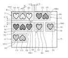
そして、制御回路30は、シート上配置処理が失敗であれば(ステップS17でNO)、ステップS20に処理を移行してディスプレイ21に上述したエラーメッセージを表示させる。一方、制御回路30は、シート上配置処理が成功であれば(ステップS17でYES)、ステップS18へ処理を移行して報知処理を実行する。これにより、図18に示すように、各グループ71~76の推奨用紙のサイズ及びその用紙の貼り付け位置を示す図形Q1~Q6と、各グループ71~76の推奨用紙のサイズを示す文字情報Q7とが、ディスプレイ21に表示される。
この場合、推奨用紙サイズの算出は、各グループ71~76の拡大包含矩形NR1~NR6に基づいて行われる。ここで、例えば全てのグループ71~76について規格紙を用いると、全ての用紙が切断可能範囲91内に収まりきらない場合がある。この場合、制御回路30は、例えば図18に示すように、各グループ71~76の拡大包含矩形NR1~NR6及びその位置を示す図形Q1~Q6を、ディスプレイ21に表示させる。
本実施形態において、推奨用紙サイズは、図18に示すように、図形Q1~Q6の場合には縦横のマス目92の数によって表され、文字情報Q7の場合には高さH[mm]×幅W[mm]等の数値で表されている。この場合、例えばマス目92を構成する縦方向及び横方向のそれぞれ罫線に対して番号を付しておき、推奨用紙の貼り付け位置のマス目92に対応する罫線の番号をディスプレイ21に表示してもよい。また、例えば次のようにしてもよい。すなわち、全てのマス目92にそれぞれ番号を付しておく。そして、推奨用紙の角部を合わせるマス目92の番号、又は推奨用紙の角部を合わせるマス目92に隣接しかつ推奨用紙が貼り付けられた際に推奨用紙によって隠れない3つのマス目92の番号をディスプレイ21に表示してもよい。
そして、制御回路30は、ステップS19において、生成処理部34の作用によって、切断データを生成する。このようにして、制御回路30は、各模様を自動配置した後の切断データを生成する。この切断データは、切断対象となる模様、この場合、模様A1~A3、B1~B3、C1、C2、D1、D2、E1、F1を全て含んだものである。
また、図19に示すように、異なるグループに属する模様のうち隣接する2つの模様は、少なくとも距離L以上離れて配置されている。ここで、複数の模様のうち任意の一の模様、例えば模様A3を基準にした場合について見る。この場合、基準になる模様A3と同一の第1グループ71に属し、かつ基準になる模様A3に隣接する他の模様A2と、その基準になる模様A3との距離を距離X1とする。また、基準になる模様A3と異なるグループ、例えば第2グループ72に属し、かつ基準になる模様A3に隣接する他の模様B3と、その基準になる模様A3との距離をX2とする。この場合、制御回路30は、距離X1よりも距離X2の方が大きくなるように、各模様を配置する。本実施形態においては、距離X1と距離X2は、それぞれ、基準になる模様と、隣接する他の模様との距離が最短となる距離である。
なお、距離X1よりも距離X2の方が大きくなるように距離Lが設定されていれば、必ずしも、各拡大包含矩形NRの角部を、図17及び図18に示すようにマス目92の角部に合わせる必要はない。この場合、拡大包含矩形NR同士が相互に重ならないように接していてもよい。
その後、制御回路30は、一連の処理を終了する(図4でエンド)。切断装置10は、ステップS19で生成した切断データに基づいて切断機構を動作させることで、切断対象となる模様を全て切断することができる。
以上の実施形態によれば、切断装置10は、切断対象となる模様に属性が異なる複数の模様が混在している場合、各模様は、同一の属性を有する模様で構成されたグループに分類される。そして、そのグループ毎に各模様を仮想的に配置した切断データが生成される。これによれば、各模様は、その属性毎にまとまって配置される。したがって、例えば色等の属性が異なる複数の模様を切断対象とした場合であっても、その属性の異なる複数種類の模様が混在した状態で、つまり各属性の模様が入り混じった状態で配置されることが無くなる。そのため、ユーザは、グループを構成する模様の属性に合わせて被切断物を配置すれば良く、その結果、保持部材に対する各被切断物の配置を容易に行うことができる。
また、制御回路30は、例えば図19に示すように、同一グループ内で隣接する模様間の距離、例えば模様A3と模様A2との距離X1よりも、異なるグループに属して隣接する模様間の距離、例えば模様A3と模様B3との距離X2の方が大きくなるように、各模様を配置した切断データを生成する。これによれば、同一グループに属する模様間の距離を小さくすることで、被切断物100の無駄を低減できる。また、グループ間の距離を大きくすることで、各グループに対応した被切断物100を保持部材90上に配置し易くなる。
また、制御回路30は、同一のグループに属する模様を全て含む矩形である包含矩形、例えば最小包含矩形R又は拡大包含矩形NRを算出する。そして、制御回路30は、各グループの最小包含矩形R又は拡大包含矩形NRが相互に重ならないように各模様を配置した切断データを生成する。これによれば、最小包含矩形R又は拡大包含矩形NRを基準にして保持部材90上に配置すべき被切断物100のサイズ及び位置を算出することで、保持部材90上に配置される被切断物100同士が重ならない。したがって、保持部材90に対する被切断物100の配置がし易くなる。
また、制御回路30は、拡大包含矩形NR同士が重ならないようにして各模様を配置した切断データを生成する。すなわち、制御回路30は、最小包含矩形Rから所定距離L拡大した範囲の外側に、他のグループに属する模様を配置した切断データを生成する。これによれば、グループ間の距離を大きく確保することができるため、被切断物100の配置がよりし易くなる。なお、最小包含矩形Rを拡大する所定距離は、最小包含矩形Rの上下左右方向において同じ距離であってもよいし、各方向に対してそれぞれ異なる距離であってもよい。
制御回路30は、グループの総数が4以下である場合に、切断可能範囲91の角部の夫々に対してグループ毎に最小包含矩形R又は拡大包含矩形NRの角部を合わせて各模様を配置した切断データを生成する。これによれば、グループの総数が4以下の場合、ユーザは、被切断物100の角部と切断可能範囲91の角部とが合うように、被切断物100を保持部材90上に配置することができるため、被切断物100の配置が更に容易になる。
また、保持部材90は所定間隔で配置されたマス目92を有している。そして、制御回路30は、グループの総数が4を超える場合、又はグループの総数が4以下であって各グループの包含矩形N、NRを切断可能範囲91の四隅に配置した場合に各包含矩形N、NRが相互に重なる場合、最小包含矩形R又は拡大包含矩形NRの角部をマス目92の角部に合わせて各模様を配置した切断データを生成する。これによれば、ユーザは、被切断物100の角部と切断可能範囲91の角部と、又は被切断物100の角部とマス目92の角部とが合うように、被切断物100を保持部材90上に配置することができるため、被切断物100の配置が更に容易になる。
そして、切断装置10は、最小包含矩形N又は拡大包含矩形NRによって定まる被切断物100のサイズと、保持部材90に対して被切断物100を配置すべき位置と、をディスプレイ21に表示する。これによれば、ユーザは、被切断物100のサイズと、保持部材90に対して被切断物100を配置すべき位置と、容易に確認することができる。
本発明は、上記した実施形態にのみ限定されるものではなく、その要旨を逸脱しない範囲で様々な拡張、変更が可能である。
上記実施形態では、複数の模様が2つのグループ又は4つのグループに分類される例を説明したが、それらの数のグループに限るものではない。例えば、特定した模様の分類の結果、グループが1つである場合にも上記実施形態の処理を適用できるし、3つのグループ、更には5つ以上のグループに分類される場合にも上記実施形態の処理を適用できる。
上述の切断データ作成プログラムは、切断装置10の制御回路30のみならず、例えばUSBメモリ、CD-ROM、フレキシブルディスク、DVD、メモリカード等の各種の記録媒体に記録される。この場合、当該記録媒体に記録されたプログラムを、種々のデータ処理装置のコンピュータに読み込んで実行させることにより、上記実施形態と同様の作用及び効果を奏する。
上記実施形態では、複数の模様が2つのグループ又は4つのグループに分類される例を説明したが、それらの数のグループに限るものではない。例えば、特定した模様の分類の結果、グループが1つである場合にも上記実施形態の処理を適用できるし、3つのグループ、更には5つ以上のグループに分類される場合にも上記実施形態の処理を適用できる。
上述の切断データ作成プログラムは、切断装置10の制御回路30のみならず、例えばUSBメモリ、CD-ROM、フレキシブルディスク、DVD、メモリカード等の各種の記録媒体に記録される。この場合、当該記録媒体に記録されたプログラムを、種々のデータ処理装置のコンピュータに読み込んで実行させることにより、上記実施形態と同様の作用及び効果を奏する。
10 切断装置
31 特定処理部
32 取得処理部
33 分類処理部
34 生成処理部
35 算出処理部
90 保持部材
91 切断可能範囲
92 マス目
31 特定処理部
32 取得処理部
33 分類処理部
34 生成処理部
35 算出処理部
90 保持部材
91 切断可能範囲
92 マス目
Claims (9)
- 切断データに基づいて保持部材上に配置された被切断物を切断する切断機構と、
切断対象となる複数の模様を特定する特定処理部と、
前記特定処理部で特定した前記模様の属性を表す属性情報を取得する取得処理部と、
前記取得処理部で取得した前記属性情報に基づいて各前記模様を2以上のグループに分類する分類処理部と、
前記保持部材によって定まる切断可能範囲内において、前記分類処理部で分類された前記グループ毎に前記模様を配置した前記切断データを生成する生成処理部と、
を備えることを特徴とする切断装置。 - 前記生成処理部は、複数の前記模様のうち任意の一の前記模様を基準にした場合に、前記基準になる模様と同一の前記グループに属しかつ前記基準になる模様に隣接する他の前記模様と前記基準になる模様との距離よりも、前記基準になる模様と異なる前記グループに属しかつ前記基準になる模様に隣接する他の前記模様と前記基準になる模様との距離を大きくした前記切断データを生成することを特徴とする、
請求項1に記載の切断装置。 - 同一の前記グループに属する前記模様を全て包含する矩形である包含矩形を算出する算出処理部を更に備え、
前記生成処理部は、各前記グループの前記包含矩形が相互に重ならないように各前記模様を配置した前記切断データを生成することを特徴とする、
請求項1又は2に記載の切断装置。 - 前記生成処理部は、前記算出処理部で算出した前記包含矩形から所定距離拡大した範囲の外側に他の前記グループに属する前記模様を配置した前記切断データを生成することを特徴とする、
請求項3に記載の切断装置。 - 前記保持部材は矩形状であって、
前記生成処理部は、前記分類処理部によって分類された前記グループの数が4以下である場合に、前記保持部材によって定まる矩形状の前記切断可能範囲の4つの角部の夫々に対して前記グループ毎に前記包含矩形の角部を合わせて各前記模様を配置した前記切断データを生成することを特徴とする、
請求項3又は4に記載の切断装置。 - 前記保持部材は所定間隔で配置されたマス目を有し、
前記生成処理部は、前記包含矩形の角部を前記マス目の角部に合わせて各前記模様を配置した前記切断データを生成することを特徴とする、
請求項3から5のいずれか一項に記載の切断装置。 - 前記包含矩形によって定まる前記被切断物のサイズと、前記保持部材に対して前記被切断物を配置すべき位置と、を報知する報知処理部を更に備えている、
請求項3から6のいずれか一項に記載の切断装置。 - 前記取得処理部は、前記属性情報として前記模様の色を示す色情報を取得することを特徴とする、
請求項1から7のいずれか一項に記載の切断装置。 - 保持部材上に載置された被切断物を切断する切断機構を備えた切断装置で用いられる切断データを生成するコンピュータによって実行される切断データ生成用プログラムであって、
前記コンピュータに、
切断対象となる複数の模様を特定する特定処理と、
前記特定処理で特定した前記模様の属性を表す属性情報を取得する取得処理と、
前記取得処理で取得した前記属性情報に基づいて各前記模様を2以上のグループに分類する分類処理と、
前記保持部材によって定まる切断可能範囲内において、前記分類処理で分類された前記グループ毎に各前記模様を配置した前記切断データを生成する生成処理と、
を実行させることができる切断データ生成用プログラム。
Priority Applications (1)
| Application Number | Priority Date | Filing Date | Title |
|---|---|---|---|
| US15/829,005 US20180079099A1 (en) | 2015-06-03 | 2017-12-01 | Cutting apparatus and non-transitory recording medium for storing cutting data genarating program |
Applications Claiming Priority (2)
| Application Number | Priority Date | Filing Date | Title |
|---|---|---|---|
| JP2015-113072 | 2015-06-03 | ||
| JP2015113072A JP2016221658A (ja) | 2015-06-03 | 2015-06-03 | 切断装置、及び切断データ生成プログラム |
Related Child Applications (1)
| Application Number | Title | Priority Date | Filing Date |
|---|---|---|---|
| US15/829,005 Continuation US20180079099A1 (en) | 2015-06-03 | 2017-12-01 | Cutting apparatus and non-transitory recording medium for storing cutting data genarating program |
Publications (1)
| Publication Number | Publication Date |
|---|---|
| WO2016194940A1 true WO2016194940A1 (ja) | 2016-12-08 |
Family
ID=57441980
Family Applications (1)
| Application Number | Title | Priority Date | Filing Date |
|---|---|---|---|
| PCT/JP2016/066161 Ceased WO2016194940A1 (ja) | 2015-06-03 | 2016-06-01 | 切断装置、及び切断データ生成プログラム |
Country Status (3)
| Country | Link |
|---|---|
| US (1) | US20180079099A1 (ja) |
| JP (1) | JP2016221658A (ja) |
| WO (1) | WO2016194940A1 (ja) |
Families Citing this family (2)
| Publication number | Priority date | Publication date | Assignee | Title |
|---|---|---|---|---|
| EP3805912B1 (en) | 2019-10-07 | 2026-01-28 | Duplo Seiko Corporation | Processing job generation apparatus and sheet processing system |
| JP7413851B2 (ja) * | 2020-03-10 | 2024-01-16 | 京セラドキュメントソリューションズ株式会社 | 画像形成装置 |
Citations (3)
| Publication number | Priority date | Publication date | Assignee | Title |
|---|---|---|---|---|
| JPS5372978A (en) * | 1976-12-10 | 1978-06-28 | Toray Ind Inc | Form piece transfer method in form piece disposing process |
| JPH08229889A (ja) * | 1995-03-02 | 1996-09-10 | Sekisui Chem Co Ltd | パネルの割付け装置 |
| JP2014176935A (ja) * | 2013-03-15 | 2014-09-25 | Brother Ind Ltd | 加工装置、及び加工装置用プログラム |
Family Cites Families (3)
| Publication number | Priority date | Publication date | Assignee | Title |
|---|---|---|---|---|
| US20050019148A1 (en) * | 2003-05-16 | 2005-01-27 | Sieber Jonathan D. | Method and apparatus for producing social stationery |
| CN102770864B (zh) * | 2010-01-29 | 2014-05-28 | 香港科技大学 | 基于图像的建筑物图案检测以及建模 |
| US8855802B2 (en) * | 2011-03-30 | 2014-10-07 | Brother Kogyo Kabushiki Kaisha | Cutting apparatus, cutting data processing device and cutting control program therefor |
-
2015
- 2015-06-03 JP JP2015113072A patent/JP2016221658A/ja active Pending
-
2016
- 2016-06-01 WO PCT/JP2016/066161 patent/WO2016194940A1/ja not_active Ceased
-
2017
- 2017-12-01 US US15/829,005 patent/US20180079099A1/en not_active Abandoned
Patent Citations (3)
| Publication number | Priority date | Publication date | Assignee | Title |
|---|---|---|---|---|
| JPS5372978A (en) * | 1976-12-10 | 1978-06-28 | Toray Ind Inc | Form piece transfer method in form piece disposing process |
| JPH08229889A (ja) * | 1995-03-02 | 1996-09-10 | Sekisui Chem Co Ltd | パネルの割付け装置 |
| JP2014176935A (ja) * | 2013-03-15 | 2014-09-25 | Brother Ind Ltd | 加工装置、及び加工装置用プログラム |
Also Published As
| Publication number | Publication date |
|---|---|
| US20180079099A1 (en) | 2018-03-22 |
| JP2016221658A (ja) | 2016-12-28 |
Similar Documents
| Publication | Publication Date | Title |
|---|---|---|
| JP6033668B2 (ja) | Cam装置及び製品形状加工方法 | |
| JP2003150220A (ja) | シミュレーション装置 | |
| JP2016221658A (ja) | 切断装置、及び切断データ生成プログラム | |
| US8149239B2 (en) | Image processing apparatus, image processing method, and storage medium storing a program for causing an image processing apparatus to execute an image processing method | |
| US20170190070A1 (en) | Cutting data creation method, cutting data creation device, and computer-readable recording medium | |
| JP2016170504A (ja) | データ生成装置、加工装置、データ生成方法、及びデータ生成プログラム | |
| JP2009252084A (ja) | 壁面用部品の板取り装置と壁面用部品の板取りプログラムと記録媒体とプレカット装置 | |
| JP2020192584A (ja) | 造形物の製造方法、積層制御装置、プログラム | |
| JP6544224B2 (ja) | レイアウトデータ作成装置、レイアウトデータ作成方法及びレイアウトデータ作成プログラム | |
| JPWO2018155698A1 (ja) | Cad装置及びプログラム | |
| JP2017027205A (ja) | 図面作成装置及び図面作成プログラム | |
| WO2016208341A1 (ja) | 切断データ作成装置、切断データ作成方法、切断データ作成プログラム | |
| JP2017030127A (ja) | 切断データ作成装置及び切断データ作成プログラム | |
| JP3951551B2 (ja) | プログラム編集装置 | |
| JP2017030130A (ja) | 切断データ作成装置及び切断データ作成プログラム | |
| JP6092048B2 (ja) | カッティングプロッタ | |
| JP2017064855A (ja) | 切断データ作成装置及び切断データ作成プログラム | |
| JP2017030129A (ja) | 切断データ作成装置及び切断データ作成プログラム | |
| JP2005286613A (ja) | 印刷データ編集装置及び印刷データ編集プログラム | |
| JP4198412B2 (ja) | 3次元形状データ処理装置、3次元形状データ処理方法、記録媒体およびプログラム | |
| JP2009134101A (ja) | データ管理装置およびパターン描画システム | |
| JP6565552B2 (ja) | 図面作成装置及び図面作成プログラム | |
| JP2017094465A (ja) | 加工データ作成装置及び加工データ作成プログラム | |
| JP2017030128A (ja) | 切断データ作成装置及び切断データ作成プログラム | |
| JP2017030126A (ja) | 切断データ作成装置及び切断データ作成プログラム |
Legal Events
| Date | Code | Title | Description |
|---|---|---|---|
| 121 | Ep: the epo has been informed by wipo that ep was designated in this application |
Ref document number: 16803374 Country of ref document: EP Kind code of ref document: A1 |
|
| NENP | Non-entry into the national phase |
Ref country code: DE |
|
| 122 | Ep: pct application non-entry in european phase |
Ref document number: 16803374 Country of ref document: EP Kind code of ref document: A1 |