WO2016194722A1 - 運転支援装置 - Google Patents
運転支援装置 Download PDFInfo
- Publication number
- WO2016194722A1 WO2016194722A1 PCT/JP2016/065401 JP2016065401W WO2016194722A1 WO 2016194722 A1 WO2016194722 A1 WO 2016194722A1 JP 2016065401 W JP2016065401 W JP 2016065401W WO 2016194722 A1 WO2016194722 A1 WO 2016194722A1
- Authority
- WO
- WIPO (PCT)
- Prior art keywords
- control
- driving
- driving support
- unit
- assistance device
- Prior art date
- Legal status (The legal status is an assumption and is not a legal conclusion. Google has not performed a legal analysis and makes no representation as to the accuracy of the status listed.)
- Ceased
Links
Images


Classifications
-
- B—PERFORMING OPERATIONS; TRANSPORTING
- B60—VEHICLES IN GENERAL
- B60W—CONJOINT CONTROL OF VEHICLE SUB-UNITS OF DIFFERENT TYPE OR DIFFERENT FUNCTION; CONTROL SYSTEMS SPECIALLY ADAPTED FOR HYBRID VEHICLES; ROAD VEHICLE DRIVE CONTROL SYSTEMS FOR PURPOSES NOT RELATED TO THE CONTROL OF A PARTICULAR SUB-UNIT
- B60W30/00—Purposes of road vehicle drive control systems not related to the control of a particular sub-unit, e.g. of systems using conjoint control of vehicle sub-units
- B60W30/10—Path keeping
- B60W30/12—Lane keeping
-
- B—PERFORMING OPERATIONS; TRANSPORTING
- B60—VEHICLES IN GENERAL
- B60W—CONJOINT CONTROL OF VEHICLE SUB-UNITS OF DIFFERENT TYPE OR DIFFERENT FUNCTION; CONTROL SYSTEMS SPECIALLY ADAPTED FOR HYBRID VEHICLES; ROAD VEHICLE DRIVE CONTROL SYSTEMS FOR PURPOSES NOT RELATED TO THE CONTROL OF A PARTICULAR SUB-UNIT
- B60W30/00—Purposes of road vehicle drive control systems not related to the control of a particular sub-unit, e.g. of systems using conjoint control of vehicle sub-units
- B60W30/14—Adaptive cruise control
- B60W30/143—Speed control
- B60W30/146—Speed limiting
-
- B—PERFORMING OPERATIONS; TRANSPORTING
- B60—VEHICLES IN GENERAL
- B60W—CONJOINT CONTROL OF VEHICLE SUB-UNITS OF DIFFERENT TYPE OR DIFFERENT FUNCTION; CONTROL SYSTEMS SPECIALLY ADAPTED FOR HYBRID VEHICLES; ROAD VEHICLE DRIVE CONTROL SYSTEMS FOR PURPOSES NOT RELATED TO THE CONTROL OF A PARTICULAR SUB-UNIT
- B60W30/00—Purposes of road vehicle drive control systems not related to the control of a particular sub-unit, e.g. of systems using conjoint control of vehicle sub-units
- B60W30/18—Propelling the vehicle
- B60W30/18009—Propelling the vehicle related to particular drive situations
- B60W30/18145—Cornering
-
- B—PERFORMING OPERATIONS; TRANSPORTING
- B60—VEHICLES IN GENERAL
- B60W—CONJOINT CONTROL OF VEHICLE SUB-UNITS OF DIFFERENT TYPE OR DIFFERENT FUNCTION; CONTROL SYSTEMS SPECIALLY ADAPTED FOR HYBRID VEHICLES; ROAD VEHICLE DRIVE CONTROL SYSTEMS FOR PURPOSES NOT RELATED TO THE CONTROL OF A PARTICULAR SUB-UNIT
- B60W40/00—Estimation or calculation of non-directly measurable driving parameters for road vehicle drive control systems not related to the control of a particular sub unit, e.g. by using mathematical models
- B60W40/02—Estimation or calculation of non-directly measurable driving parameters for road vehicle drive control systems not related to the control of a particular sub unit, e.g. by using mathematical models related to ambient conditions
- B60W40/06—Road conditions
- B60W40/072—Curvature of the road
-
- B—PERFORMING OPERATIONS; TRANSPORTING
- B60—VEHICLES IN GENERAL
- B60W—CONJOINT CONTROL OF VEHICLE SUB-UNITS OF DIFFERENT TYPE OR DIFFERENT FUNCTION; CONTROL SYSTEMS SPECIALLY ADAPTED FOR HYBRID VEHICLES; ROAD VEHICLE DRIVE CONTROL SYSTEMS FOR PURPOSES NOT RELATED TO THE CONTROL OF A PARTICULAR SUB-UNIT
- B60W50/00—Details of control systems for road vehicle drive control not related to the control of a particular sub-unit, e.g. process diagnostic or vehicle driver interfaces
- B60W50/08—Interaction between the driver and the control system
- B60W50/14—Means for informing the driver, warning the driver or prompting a driver intervention
-
- B—PERFORMING OPERATIONS; TRANSPORTING
- B62—LAND VEHICLES FOR TRAVELLING OTHERWISE THAN ON RAILS
- B62D—MOTOR VEHICLES; TRAILERS
- B62D15/00—Steering not otherwise provided for
- B62D15/02—Steering position indicators ; Steering position determination; Steering aids
- B62D15/025—Active steering aids, e.g. helping the driver by actively influencing the steering system after environment evaluation
-
- B—PERFORMING OPERATIONS; TRANSPORTING
- B62—LAND VEHICLES FOR TRAVELLING OTHERWISE THAN ON RAILS
- B62D—MOTOR VEHICLES; TRAILERS
- B62D7/00—Steering linkage; Stub axles or their mountings
- B62D7/06—Steering linkage; Stub axles or their mountings for individually-pivoted wheels, e.g. on king-pins
- B62D7/14—Steering linkage; Stub axles or their mountings for individually-pivoted wheels, e.g. on king-pins the pivotal axes being situated in more than one plane transverse to the longitudinal centre line of the vehicle, e.g. all-wheel steering
- B62D7/15—Steering linkage; Stub axles or their mountings for individually-pivoted wheels, e.g. on king-pins the pivotal axes being situated in more than one plane transverse to the longitudinal centre line of the vehicle, e.g. all-wheel steering characterised by means varying the ratio between the steering angles of the steered wheels
- B62D7/159—Steering linkage; Stub axles or their mountings for individually-pivoted wheels, e.g. on king-pins the pivotal axes being situated in more than one plane transverse to the longitudinal centre line of the vehicle, e.g. all-wheel steering characterised by means varying the ratio between the steering angles of the steered wheels characterised by computing methods or stabilisation processes or systems, e.g. responding to yaw rate, lateral wind, load, road condition
-
- G—PHYSICS
- G08—SIGNALLING
- G08G—TRAFFIC CONTROL SYSTEMS
- G08G1/00—Traffic control systems for road vehicles
- G08G1/16—Anti-collision systems
- G08G1/167—Driving aids for lane monitoring, lane changing, e.g. blind spot detection
-
- B—PERFORMING OPERATIONS; TRANSPORTING
- B60—VEHICLES IN GENERAL
- B60W—CONJOINT CONTROL OF VEHICLE SUB-UNITS OF DIFFERENT TYPE OR DIFFERENT FUNCTION; CONTROL SYSTEMS SPECIALLY ADAPTED FOR HYBRID VEHICLES; ROAD VEHICLE DRIVE CONTROL SYSTEMS FOR PURPOSES NOT RELATED TO THE CONTROL OF A PARTICULAR SUB-UNIT
- B60W2420/00—Indexing codes relating to the type of sensors based on the principle of their operation
- B60W2420/40—Photo, light or radio wave sensitive means, e.g. infrared sensors
- B60W2420/403—Image sensing, e.g. optical camera
-
- B—PERFORMING OPERATIONS; TRANSPORTING
- B60—VEHICLES IN GENERAL
- B60W—CONJOINT CONTROL OF VEHICLE SUB-UNITS OF DIFFERENT TYPE OR DIFFERENT FUNCTION; CONTROL SYSTEMS SPECIALLY ADAPTED FOR HYBRID VEHICLES; ROAD VEHICLE DRIVE CONTROL SYSTEMS FOR PURPOSES NOT RELATED TO THE CONTROL OF A PARTICULAR SUB-UNIT
- B60W2520/00—Input parameters relating to overall vehicle dynamics
- B60W2520/10—Longitudinal speed
-
- B—PERFORMING OPERATIONS; TRANSPORTING
- B60—VEHICLES IN GENERAL
- B60W—CONJOINT CONTROL OF VEHICLE SUB-UNITS OF DIFFERENT TYPE OR DIFFERENT FUNCTION; CONTROL SYSTEMS SPECIALLY ADAPTED FOR HYBRID VEHICLES; ROAD VEHICLE DRIVE CONTROL SYSTEMS FOR PURPOSES NOT RELATED TO THE CONTROL OF A PARTICULAR SUB-UNIT
- B60W2540/00—Input parameters relating to occupants
- B60W2540/18—Steering angle
-
- B—PERFORMING OPERATIONS; TRANSPORTING
- B60—VEHICLES IN GENERAL
- B60W—CONJOINT CONTROL OF VEHICLE SUB-UNITS OF DIFFERENT TYPE OR DIFFERENT FUNCTION; CONTROL SYSTEMS SPECIALLY ADAPTED FOR HYBRID VEHICLES; ROAD VEHICLE DRIVE CONTROL SYSTEMS FOR PURPOSES NOT RELATED TO THE CONTROL OF A PARTICULAR SUB-UNIT
- B60W2552/00—Input parameters relating to infrastructure
- B60W2552/05—Type of road, e.g. motorways, local streets, paved or unpaved roads
-
- B—PERFORMING OPERATIONS; TRANSPORTING
- B60—VEHICLES IN GENERAL
- B60W—CONJOINT CONTROL OF VEHICLE SUB-UNITS OF DIFFERENT TYPE OR DIFFERENT FUNCTION; CONTROL SYSTEMS SPECIALLY ADAPTED FOR HYBRID VEHICLES; ROAD VEHICLE DRIVE CONTROL SYSTEMS FOR PURPOSES NOT RELATED TO THE CONTROL OF A PARTICULAR SUB-UNIT
- B60W2552/00—Input parameters relating to infrastructure
- B60W2552/30—Road curve radius
-
- B—PERFORMING OPERATIONS; TRANSPORTING
- B60—VEHICLES IN GENERAL
- B60W—CONJOINT CONTROL OF VEHICLE SUB-UNITS OF DIFFERENT TYPE OR DIFFERENT FUNCTION; CONTROL SYSTEMS SPECIALLY ADAPTED FOR HYBRID VEHICLES; ROAD VEHICLE DRIVE CONTROL SYSTEMS FOR PURPOSES NOT RELATED TO THE CONTROL OF A PARTICULAR SUB-UNIT
- B60W2556/00—Input parameters relating to data
- B60W2556/45—External transmission of data to or from the vehicle
- B60W2556/50—External transmission of data to or from the vehicle of positioning data, e.g. GPS [Global Positioning System] data
Definitions
- the present invention relates to a technology that supports at least a part of a driving operation by a driver.
- Patent Document 1 Various driving support control technologies that support at least part of driving operations by drivers have been proposed.
- the driving support system notifies the driver that a predetermined condition for executing driving support control is established, and the driving support system executes driving support control when the driver releases his handle. Techniques to do this are disclosed.
- Patent Literature 1 when it is detected that the driver has touched a specific position on the steering wheel during the driving support control, it is determined that the condition for ending the driving support control is satisfied, and the driving support control is ended. Then, it shifts to the driving operation by the driver.
- the vehicle may travel on a road with a large degree of bending.
- the driver immediately shifts from the driving support control to the driving operation by the driver, the driver suddenly responds to the difficult situation of the driving operation to drive the driving road with a large degree of bending. It will be a burden.
- the present invention has been made in view of the above, and when the condition for ending the driving support control and shifting to the driving operation by the driver is satisfied, the burden of the driving operation by the driver is reduced as much as possible according to the bending condition of the traveling path. It aims at providing the technology to reduce.
- a driving support apparatus includes a driving support control unit, a support determination unit, a physical quantity acquisition unit, a bending condition determination unit, and an end command unit.
- the driving support control unit executes driving support control that supports at least a part of the driving operation by the driver.
- the support determination unit determines whether or not a predetermined condition for the driving support control unit to end the driving support control is satisfied.
- the physical quantity acquisition unit acquires a physical quantity corresponding to the degree of bending of the travel path on which the host vehicle travels.
- the bend state determination unit determines whether the bend state indicated by the physical quantity acquired by the physical amount acquisition unit is smaller than a predetermined size. .
- the end command unit instructs the drive support control unit to end the drive support control.
- the driving support control is continued when the degree of bending of the travel path on which the host vehicle travels is a predetermined magnitude or more.
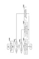
- the block diagram which shows the driving assistance system by this embodiment The functional block diagram of the LTC part in the driving assistance system of FIG. 1A.
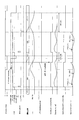
- the flowchart which shows the process by a camera part. The schematic diagram explaining calculation of a curvature.
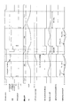
- the other schematic diagram explaining calculation of a curvature. The flowchart which shows the detection process of LTC starting SW.
- the flowchart which shows LTC processing. The flowchart which shows LTC processing.
- (1. Configuration) 1A includes a driving support device 10, a camera unit 20, an LTC (Lane Trace Control) activation switch (SW) 22, a vehicle speed setting device 24, a navigation device 26, a vehicle speed sensor 28, and the like. , An HMI (Human Machine Interface) unit 30, a steering system 40, a powertrain system 42, and a brake system 44.
- a vehicle equipped with the driving support system 2 is referred to as a host vehicle.
- the driving support device 10 is equipped with a computer having a CPU (central processing unit), a RAM (random access memory), a ROM (read-only memory), an input / output interface, etc., and the CPU is stored in the ROM. By executing various programs, it functions as the LTC unit 12, the lateral motion control unit 14, and the longitudinal motion control unit 16.
- the LTC unit 12 executes lane trace control that causes the host vehicle to travel on a travel path that is divided into left and right by a white line on which the host vehicle is currently traveling, based on image data captured by the camera unit 20.
- the lateral motion control unit 14 instructs the steering system 40 on the torque to drive the steering wheel based on the parameters and flags acquired from the LTC unit 12 in the lane trace control.
- the lateral movement control unit 14 commands the steering system 40 with a torque for driving the steering wheel, so that the host vehicle travels in the commanded lateral position on the travel path.
- the front-rear motion control unit 16 instructs the powertrain system 42 to drive the vehicle to travel based on the parameters and flags acquired from the LTC unit 12, and instructs the brake system 44 to apply the braking force. To do.
- the front-rear direction motion control unit 16 commands the powertrain system 42 to output a drive and commands the brake system 44 to apply a braking force, so that the host vehicle travels at the commanded vehicle speed set by the vehicle speed setting unit 24 in the lane trace control. To do.
- the vehicle speed setting device 24 is used when the host vehicle follows the preceding vehicle or when leaving the automobile exclusive road.
- the command vehicle speed is appropriately reduced regardless of the set vehicle speed.
- the camera unit 20 generates, for example, left and right white lines that define a travel path on which the host vehicle travels based on image data captured by a camera attached near the center of a mirror of a window shield in the vehicle interior of the host vehicle. Detection is based on the luminance difference between the white line and the road surface.
- the camera unit 20 calculates the curvature of the traveling road based on, for example, the coordinates of the left and right white lines detected as described later. Further, the camera unit 20 calculates the yaw angle of the host vehicle and the lateral position of the host vehicle with respect to the reference point of the travel path based on the image data.
- the LTC activation SW 22 is a lever switch attached to the center portion of the steering handle, and can select either the on or off position from the reference position by the driver's operation. When the driver selects on or off from the reference position of the LTC activation SW 22 and releases the hand, the LTC activation SW 22 returns from the on or off to the reference position.
- the LTC unit 12 determines that the driver has instructed activation of the lane trace control.
- the LTC unit 12 determines that the driver has commanded the end of the lane trace control.
- the vehicle speed setter 24 is used by a driver to input a command vehicle speed when the LTC unit 12 executes lane trace control by operating a touch panel or the like.
- the navigation device 26 guides the route to the destination based on the current position of the host vehicle and the destination of the host vehicle input from the touch panel or the like.
- the navigation device 26 receives a positioning signal from a positioning satellite such as a GPS satellite, and maps the position of the host vehicle based on map information stored in the map DB.
- the navigation device 26 acquires the passage of the ETC gate from the ETC device if it is a toll road, so that it can enter the vehicle-only road and only for the vehicle. The exit from the road is detected and transmitted to the LTC unit 12.
- ETC Electronic Toll Collection System: registered trademark
- the navigation device 26 detects entry into and exit from the automobile road based on the position of the own vehicle, and the LTC unit 12 You may send it.
- the HMI unit 30 notifies the driver of the execution state of the lane trace control according to an instruction from the LTC unit 12 using at least one of sound, image, and light.
- the steering system 40 drives the steering handle according to the torque commanded from the lateral motion control unit 14 and controls the lateral motion of the host vehicle.
- the powertrain system 42 controls the opening degree of the throttle device and the fuel injection amount according to the drive output commanded from the longitudinal motion control unit 16 as a drive source.
- the power supplied to the motor is controlled.
- the brake system 44 controls the actuator provided in the hydraulic circuit of the hydraulic brake according to the braking force commanded from the longitudinal motion control unit 16.
- the brake system 44 controls the power supplied to the motor in accordance with the braking force commanded from the front-rear direction motion control unit 16 and the braking force by the regenerative braking. May be generated.
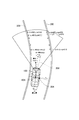
- step S400 of FIG. 2 the camera unit 20 detects a white line from the captured image data, and uses the positions of the white lines on both the left and right sides up to about 150 m ahead of the traveling direction as the boundary position of the traveling path on which the vehicle will travel. calculate.
- the camera unit 20 uses, for example, the center of gravity 102 of the host vehicle 100 as the origin, the horizontal direction of the host vehicle 100 as the x axis, and the direction orthogonal to the x axis as the y axis. That is, the y axis represents the direction of the host vehicle 100. And the camera part 20 calculates the position of the white lines 200 and 202 on either side from the own vehicle 100 to about 150 m ahead.
- the camera unit 20 acquires the x-coordinate and y-coordinate of the position of the left white line 200 from (x_left [0], y_left [0]) to (x_left [n], y_left [n]). Further, the camera unit 20 acquires the x coordinate and the y coordinate of the position of the white line 202 on the right side from (x_right [0], y_right [0]) to (x_right [n], y_right [n]).
- the camera unit 20 sets the curvature (rho) of the traveling path of the host vehicle defined by the coordinate positions of the left and right white lines 200 and 202 calculated in step S400, for example, about 150 m ahead of the host vehicle 100. 15 are calculated every 10 m.
- the curvature (rho) of the travel path the curvature of one of the left and right white lines 200 and 202 may be calculated, or the curvature of the center line of the travel path passing through the center position 204 in the width direction of the travel path is calculated. Also good.
- the curvature of the travel path ahead of the host vehicle 100 in the travel direction is calculated as a physical quantity corresponding to the degree of curvature of the travel path ahead of the host vehicle 100 in the travel direction.
- the camera unit 20 sets the left and right boundary lines 220 and 222 so as to avoid the obstacle 300 instead of the left and right white lines 210 and 212.
- the x and y coordinates of the boundary lines 220 and 222 are calculated in the same manner as the white lines 210 and 212.
- the camera unit 20 travels the host vehicle defined by the coordinate positions of the left and right white lines 210 and 212 and the boundary lines 220 and 222 instead of the white lines 210 and 212 in the range where the boundary lines 220 and 222 are set.
- the curvature of the road is calculated every 10 m from the own vehicle 100 to about 150 m ahead.
- the camera unit 20 calculates the yaw angle and the lateral position of the host vehicle.
- the yaw angle (theta) of the host vehicle represents an angle formed by the y-axis that is the direction of the host vehicle and the tangent line 206 of the travel path at the center of gravity 102 of the host vehicle 100 as shown in FIG.
- the lateral position (yc) represents the distance from the center position 204 of the travel path passing through the center of gravity 102 of the host vehicle 100 to the center of gravity 102 of the host vehicle 100.
- step S410 of FIG. 5 when the driver turns on the LTC activation SW 22 (step S410: Yes), the LTC activation SW 22 turns on driver_apl_sw_flg and initializes the counter to 0 (step S412). If the driver_apl_sw_flg is on, it indicates that the driver has turned on the LTC start SW22 to instruct the start of lane trace control, and if off, the driver has turned off the LTC start SW22 and instructed the end of the lane trace control. It is a flag indicating that it has been done.
- step S410 When the driver turns off the LTC activation SW 22 instead of on (step S410: No, step S414: Yes), the LTC activation SW 22 turns off the driver_apl_sw_flg and initializes the counter to 0 (step S416).
- step S410 If the driver does not turn on or off the LTC activation SW 22 (step S410: No, step S414: No), the LTC activation SW 22 increments the counter by 1 (step S418), and the counter value is set to a predetermined constant (step S418). It is determined whether or not (CNT_TH) or more (step S420). Since the processing of FIG. 5 is executed at predetermined time intervals, whether or not the counter value is equal to or greater than a constant (CNT_TH) is determined by determining whether or not a predetermined time corresponding to the constant (CNT_TH) has elapsed. It represents.
- step S420: Yes the LTC activation SW 22 sets the driver_apl_sw_flg to neutral and sets the counter to 0 (step S422). Setting the driver_apl_sw_flg to neutral in step S422 indicates that the LTC activation SW 22 has not been operated either on or off and a predetermined time has elapsed.
- step S420: No the LTC activation SW 22 ends this process. That is, when the driver turns on the LTC activation SW 22, the driver_apl_sw_flg is kept on until the counter value becomes CNT_TH or more and a predetermined time elapses. When the driver turns off the LTC activation SW 22, the driver_apl_sw_flg continues to be turned off until the counter value becomes equal to or greater than CNT_TH and a predetermined time elapses.
- step S430 of FIG. 6 the LTC unit 12 acquires driveway_state and rho from the camera unit 20, acquires driver_apl_sw_flg from the LTC activation SW 22, and acquires the HMI_state set by the LTC unit 12 itself.
- HMI_state represents the content that the HMI unit 30 informs the driver of the execution state of the lane trace control based on an instruction from the LTC unit 12.
- the notification contents of HMI_state are the following five types (1) to (5).
- the content of the HMI_state is notified by at least one of sound, image, and light using at least one of a speaker and a display.
- the initial value of HMI_state is NON_DISPLAY.
- LTC_ENABLE LTC executable
- LTC_CTRL LTC running
- LTC_DESABLE_WARNING LTC end notice
- LTC_HANDOVER Driver sovereignty to YN_DISP None of 2) to 5 indicates that there is no content for notifying the driver of the execution state of the lane trace control.
- LTC_ENABLE indicates that the host vehicle can enter the automobile road and execute the lane trace control, but the LTC activation SW 22 is not yet turned on.
- LTC_CTRL indicates that lane trace control is being executed.
- LTC_DESABLE_WARNING the conditions for ending the lane trace control after the own vehicle exits from the automobile-only road are satisfied, but the lane trace control is large and the lane trace control is large. It means that it is waiting.
- LTC_HANDOVER indicates that the lane trace control is finished and a process for transferring the sovereignty of the driving operation to the driver is started.
- step S432 Yes
- step S434 the LTC unit 12 sets the values of various parameters as follows (step S436).
- HMI_state LTC_ENABLE
- lateral_control_enable_flg off
- longitudinal_control_ref 0.
- step S434 As shown in FIG. 10 and FIG. 11, when the host vehicle enters the automobile exclusive road, the HMI_state is set from NON_DISPLAY to LTC_ENABLE in step S436, so the determination in step S434 becomes “No” in the next processing, and step The process proceeds to S438.
- Lateral_control_enable_flg indicates that the lateral movement of the vehicle is being controlled by steering control that drives the steering wheel in lane trace control, and if it is off, steering control that drives the steering wheel is stopped. Represents. Lateral_control_ref represents the command lateral position for the host vehicle.
- the center position 204 in the width direction of the travel path that is, the middle position between the white line 200 on the left side and the white line 202 on the right side is set as the command lateral position.
- the center position in the width direction of the travel path defined by the left boundary line 220 including the white lines 200 and 210 and the right boundary line 222 is set as the command lateral position.
- Longitudinal_control_enable_flg indicates that the vehicle speed control of the host vehicle is being executed by the powertrain system 42 and the brake system 44 in the lane trace control if it is on, and the vehicle speed control of the host vehicle is stopped if it is off.
- longitudinal_control_ref represents a command acceleration for the host vehicle for controlling the vehicle speed of the host vehicle to the command vehicle speed set by the vehicle speed setter 24.
- the LTC unit 12 sets the values of various parameters as shown in FIG. 10 and FIG. (Step S440).
- lateral_control_enable_flg If lateral_control_enable_flg is on, it means that the lateral movement control for controlling the lateral position of the host vehicle is executed by executing steering control for the steering wheel in the lane trace control, and if it is off, the lateral movement control is terminated. Represents.
- Longitudinal_control_enable_flg indicates that the vehicle motion of the host vehicle is controlled to the command vehicle speed set by the vehicle speed setting device 24 in the lane trace control if it is on, and the longitudinal motion control is terminated if it is off. Indicates to do.
- step S440 the LTC unit 12 calculates a command acceleration (longitudinal_control_ref) for the host vehicle based on the following equations (1) to (3) (step S440).
- diffV Vspd_ref ⁇ Vspd (1)
- diffV_int DiffV_int [n-1] + (diffV [n-1] + diffV) * TS / 2
- longitudinal_control_ref KP_LONG * diffV + KI_LONG * diffV_int ...
- diffV represents the difference between the command vehicle speed (Vspd_ref) and the actual vehicle speed (Vspd).
- diffV_int is obtained by adding the sum of the difference between the command vehicle speed and the actual vehicle speed in the time interval (TS) between the previous process and the current process to the sum of the difference between the command vehicle speed and the actual vehicle speed until the previous time. Value. That is, diffV_int represents the integration of the difference between the command vehicle speed up to this time and the actual vehicle speed.
- the LTC start SW 22 is operated to be turned off from the reference position while the host vehicle is traveling on the automobile exclusive road, or it is started to transfer the sovereignty of the driving operation to the driver.
- the LTC unit 12 sets the values of various parameters as follows (step S444).
- HMI_state When HMI_state is set to LTC_handover, it is notified by at least one of sound, image, and light that transfer of sovereignty of driving operation to the driver is started.
- the handover_timer measures the period for notifying that the transfer of the sovereignty of the driving operation to the driver is started.
- HOV_TH represents a period for informing that the transfer of the sovereignty of the driving operation to the driver is started.
- step S446 Yes
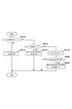
- step S450 of FIG. 7 the LTC unit 12 determines whether or not the conditions (1) to (3) described below are satisfied at the same time.
- max (rho) ⁇ RHO_TH If max (rho) ⁇ RHO_TH in step S450, the maximum value (max (rho)) of the curvature of the traveling path ahead of the traveling direction of the host vehicle is a predetermined value when the host vehicle leaves the automobile exclusive road. It represents that it is more than a certain RHO_TH.
- max (rho) is the maximum value of 15 curvatures calculated at intervals of 10 m on the traveling road ahead in the traveling direction of the host vehicle. As the curvature increases, the radius of curvature of the travel path decreases. Therefore, the curvature increases as the curvature increases.
- the above conditions (1) and (2) are satisfied, and the above condition (3) is established in which the degree of bending of the traveling road ahead of the own vehicle in the traveling direction after exiting the automobile exclusive road is greater than or equal to a predetermined value.
- the LTC unit 12 does not immediately transfer the sovereignty of the driving operation to the driver, but continues the lane trace control by executing the processes of steps S452 to S458 below.
- step S450 When the above conditions (1) to (3) are simultaneously satisfied (step S450: Yes), the LTC unit 12 sets HMI_state to LTC_DESABLE_WARNING and notifies the driver that the lane trace control is finished (step S452). . In this case, in addition to notifying the end of the lane trace control, the lane trace control will be ended soon, so that the driver may be notified of the driving operation such as “hold the steering wheel”.
- LTC unit 12 increments the LTC_shotdown_timer by 1 (step S452).
- LTC_shotdown_timer is a timer for measuring an elapsed time after the host vehicle leaves the automobile road.
- step S454 when the LTC_shotdown_timer becomes equal to or greater than SDT_TH (step S454: Yes), the LTC unit 12 has a predetermined elapsed time since the end of the lane trace control after the vehicle exited the automobile exclusive road. It is determined that SDT_TH, which is the time, has elapsed, LTC_HANDOVER is set in HMI_state, and LTC_shotdown_timer is initialized to 0 (step S456).
- step S458 when longitudinal_control_ref is set based on the above-described equations (1) to (3) in step S458, the host vehicle exits from the road for exclusive use of the car, so that regardless of the vehicle speed set by the driver using the vehicle speed setter 24.
- the command vehicle speed (Vspd_ref) is decelerated, for example, to the speed limit for passing through the ETC gate and the speed limit for the exit road until the vehicle enters the general road.
- step S450 after the own vehicle leaves the car-only road is “No” when rho ⁇ RHO_TH or when LTC_shotdown_timer ⁇ SDT_TH.
- the curve of the traveling path becomes smaller than a predetermined value before a predetermined time has elapsed after the own vehicle exits the automobile exclusive road, or as shown in FIG. This is when a predetermined time elapses after the vehicle leaves the automobile road.
- the LTC activation SW 22 is not moved from the reference position.
- the process of transferring the sovereignty of the driving operation to the driver is immediately executed.
- driver_apl_sw_flg off, the driver is instructing transfer of the sovereignty of the driving operation.
- HMI_state LTC_CTRL
- step S460 LTC_HANDOVER
- HMI_state LTC_HANDOVER
- driver_apl_sw_flg off or HMI_state is other than NON_DISPLAY (step S460: Yes)
- the LTC unit 12 sets values of various parameters in the same manner as step S444 in FIG. 6 (step S462).
- step S ⁇ b> 470 of FIG. 8 the lateral motion control unit 14 acquires lateral_control_enable_flg, lateral_control_ref, max (rho), metadata, yc from the LTC unit 12.
- step S476 Yes
- the lateral motion control unit 14 determines that the lane trace control is being executed, and determines the steering wheel based on the following expressions (4) to (6).
- a torque control command value (handle_trq_ref) for executing the steering control for is calculated (step S478).
- diffy lateral_control_ref-yc ...
- diffy represents the difference between the command lateral position and the lateral position of the center of gravity 102 of the host vehicle 100.
- lateral_control_ref 0.
- diffy_int is the sum of the difference between the previous command lateral position and the actual lateral position, and the difference between the command lateral position and the actual lateral position in the time interval (TS) between the previous and current processing. It is a value obtained by adding the integration of the difference. That is, diffy_int represents the integration of the difference between the commanded lateral position up to this time and the actual lateral position.
- step S480: Yes) the lateral motion control unit 14 determines that the end of the lane trace control has been commanded, and controls the sovereignty of the driving operation. The process to transfer to the driver is started.
- step S482 the lateral motion control unit 14 sets the smoothing rate (K_NAMASI ⁇ 1) of the torque control command value for executing the steering control smoothing process for the steering wheel, and max (rho) as the parameter. Is calculated from the map by the following equation (7).
- K_NAMASI MAP (max (rho)) (7) It is desirable that the greater the maximum value of the travel path curvature, that is, the greater the maximum value of the travel path bend, the smaller the smoothing rate and the lower the torque control command value. As a result, the amount of driving operation of the steering wheel by the driver can be increased gradually, and the burden of driving operation by the driver can be increased gradually.
- handle_trq_ref handle_trq_ref * K_NAMES (8) Since K_NAMASI ⁇ 1, every time step S484 is executed, the absolute value of handle_trq_ref calculated in step S484 becomes smaller as indicated by the period of the annealing process in FIGS.
- step S486 When the absolute value of handle_trq_ref becomes equal to or less than the predetermined value HTRQ_TH (step S486: Yes), the lateral motion control unit 14 sets handle_trq_ref to 0 and ends the annealing process as shown in FIGS. (Step S488). Thereby, when the torque command control value becomes equal to or lower than HTRQ_TH, the annealing process can be ended.
- handle_trq_ref While the absolute value of handle_trq_ref is larger than HTRQ_TH (step S486: No), the lateral motion control unit 14 continues the annealing process.
- step S ⁇ b> 490 of FIG. 9 the longitudinal motion control unit 16 acquires longitudinal_control_enable_flg and longitudinal_control_ref from the LTC unit 12.
- longitudinal_control_enable_flg ON, that is, when lane trace control is being performed (step S492: Yes)
- the longitudinal motion control unit 16 determines whether or not longitudinal_control_ref ⁇ 0 (step S494).
- step S494 Yes
- the longitudinal motion control unit 16 calculates the drive output (powertrain_control_ref) commanded to the powertrain system 42 from the following equation (9). (Step S496).
- powertrain_control_ref longitudinal_control_ref * VEHICLE_MASS ... (9)
- the longitudinal motion control unit 16 sets the braking force (break_control_ref) commanded to the brake system 44 to 0 (step S496).
- step S494 When longitudinal_control_ref ⁇ 0 (step S494: No), that is, when the commanded acceleration is negative, the longitudinal motion control unit 16 calculates the braking force (break_control_ref) commanded to the brake system 44 from the following formula (10) (step 10). S498).
- break_control_ref longitudinal_control_ref * VEHICLE_MASS (10)
- the longitudinal motion control unit 16 sets the drive output (powertrain_control_ref) commanded to the powertrain system 42 to 0 (step S498).
- step S492 No
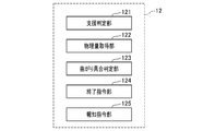
- FIG. 1B shows functional blocks representing the functions of the LTC unit 2.
- the LTC unit 2 includes functional blocks such as a support determination unit 121, a physical quantity acquisition unit 122, a bending state determination unit 123, an end command unit 124, and a notification command unit 125.
- the support determination unit 121 is a functional block that executes Step S432, and is configured to determine whether or not a predetermined condition for the driving support control unit 17 to end the driving support control is satisfied. For example, the support determination unit 121 may determine that the predetermined condition is satisfied when the host vehicle exits the automobile-only road.
- the physical quantity acquisition unit 122 is a functional block that executes Step S450, and is configured to acquire a physical quantity corresponding to the degree of bending of the travel path on which the host vehicle travels.
- the bending state determination unit 123 is also a functional block that executes step S450.
- the support determination unit 121 determines that a predetermined condition is satisfied, the bending state indicated by the physical quantity acquired by the physical quantity acquisition unit 122 is greater than a predetermined size. It is determined whether or not it is small.
- the physical quantity acquisition unit 122 acquires the curvature of the traveling road as the physical quantity, and the bending condition determination unit 123 determines whether the bending condition is smaller than the predetermined magnitude depending on whether the curvature is smaller than a predetermined value.
- the physical quantity acquisition unit 122 may acquire, as the curvature of the travel path, the curvature of the travel path ahead of the host vehicle in the travel direction based on, for example, map information. Alternatively or additionally, the physical quantity acquisition unit 122 acquires a steering angle, and the bending condition determination unit 123 determines whether the bending condition is smaller than the predetermined magnitude depending on whether the steering angle is smaller than a predetermined value. May be configured to determine.
- the end command unit 124 is a functional block that executes Step S462.
- the bend state determination unit determines that the bend state is smaller than the predetermined size
- the end command unit 124 instructs the drive support control unit to end the drive support control.
- the end command unit 124 is a functional block that further executes steps S454 and S456.
- steps S454 and S456 When a predetermined time elapses after the predetermined condition is satisfied, the driving support is performed even if the bending degree is equal to or greater than the predetermined magnitude.
- the control unit is instructed to end the driving support control.
- the notification command unit 125 is a functional block that executes Step S452, and is configured to notify the end of the driving support control before the end command unit instructs the driving support control unit to end the driving support control. Is done.
- the lateral motion control unit 14 that executes steps S470 to S488 and the longitudinal motion control unit 16 that executes steps S490 to S500 perform at least a part of the driving operation by the driver.
- a driving support control unit 17 that executes driving support control to be supported is configured. As shown in steps S482 to S486, the driving support control unit 17 is configured to gradually decrease the control amount by the driving support control when the end command unit 124 instructs the end of the driving support control. At this time, the driving support control unit 17 adjusts the degree of decrease in the control amount according to the physical quantity, for example, the vehicle speed of the host vehicle.
- the driving support control unit 17 performs steps S470 to S488 through the lateral motion control unit 14 to support steering control.
- the driving support control unit 17 performs steps S490 to S500 through the longitudinal motion control unit 16 to support vehicle speed control.
- the curvature of the travel path is used as a physical quantity corresponding to the degree of bending of the travel path of the host vehicle.
- a steering angle, a lateral acceleration of the host vehicle detected by an acceleration sensor, or the like may be used as a physical quantity corresponding to the curve of the traveling path of the host vehicle. It can be determined that the greater the steering angle, the greater the curve of the travel path, and the greater the lateral acceleration, the greater the curve of the travel path.
- the lateral motion control unit 14 acquires the steering angle from the steering system 40 as shown in FIG. 1A.
- the driving support device 10 may acquire the curvature of the travel path from the map information of the map DB provided in the navigation device 26 shown in FIG. 1A instead of the image data captured by the camera unit 20.
- the smoothing rate of the torque control command value for driving the steering wheel may be variably set according to the vehicle speed.
- the degree of decrease in torque control command value may be reduced by decreasing the smoothing rate as the vehicle speed increases.
- the lane trace control is ended even if the curvature is equal to or greater than the predetermined value.
- the predetermined time may be set longer as the curvature increases in a range where the curvature is equal to or greater than a predetermined value.
- the lane trace control is executed as the driving support control when the host vehicle enters the automobile road and the driver turns on the LTC activation SW 22.
- the driving support control may be executed when the LTC activation SW 22 is turned on regardless of whether or not the own vehicle has entered the automobile road.
- both the vehicle speed control and the steering control of the host vehicle are controlled as the driving support control.
- only one of the vehicle speed control or the steering control of the host vehicle may be controlled as the driving support control.
- the condition for terminating the lane trace control as the driving support control is that the host vehicle exits from the automobile-only road.
- the driver turns off the LTC start SW 22 during the driving support control or whether the driver operates the steering handle while holding the steering handle, regardless of whether or not the own vehicle exits from the automobile road.
- the driving support control may be terminated.
- a driving support system 2 including the driving support device 10 as a constituent element, a driving support program for causing a computer to function as the driving support device 10, and the driving support program are recorded.
- the present invention can also be realized in various forms such as a recording medium and a driving support method.
Landscapes
- Engineering & Computer Science (AREA)
- Transportation (AREA)
- Mechanical Engineering (AREA)
- Automation & Control Theory (AREA)
- Physics & Mathematics (AREA)
- Mathematical Physics (AREA)
- Combustion & Propulsion (AREA)
- Chemical & Material Sciences (AREA)
- Human Computer Interaction (AREA)
- General Physics & Mathematics (AREA)
- Theoretical Computer Science (AREA)
- Steering Control In Accordance With Driving Conditions (AREA)
- Control Of Driving Devices And Active Controlling Of Vehicle (AREA)
- Traffic Control Systems (AREA)
Priority Applications (1)
| Application Number | Priority Date | Filing Date | Title |
|---|---|---|---|
| US15/579,124 US11014556B2 (en) | 2015-06-04 | 2016-05-25 | Driving support apparatus |
Applications Claiming Priority (2)
| Application Number | Priority Date | Filing Date | Title |
|---|---|---|---|
| JP2015-114163 | 2015-06-04 | ||
| JP2015114163A JP6390525B2 (ja) | 2015-06-04 | 2015-06-04 | 運転支援装置 |
Publications (1)
| Publication Number | Publication Date |
|---|---|
| WO2016194722A1 true WO2016194722A1 (ja) | 2016-12-08 |
Family
ID=57440584
Family Applications (1)
| Application Number | Title | Priority Date | Filing Date |
|---|---|---|---|
| PCT/JP2016/065401 Ceased WO2016194722A1 (ja) | 2015-06-04 | 2016-05-25 | 運転支援装置 |
Country Status (3)
| Country | Link |
|---|---|
| US (1) | US11014556B2 (enExample) |
| JP (1) | JP6390525B2 (enExample) |
| WO (1) | WO2016194722A1 (enExample) |
Families Citing this family (3)
| Publication number | Priority date | Publication date | Assignee | Title |
|---|---|---|---|---|
| KR102262132B1 (ko) * | 2017-03-27 | 2021-06-10 | 현대자동차주식회사 | 차량용 조향 제어방법 |
| KR102532338B1 (ko) | 2018-06-21 | 2023-05-16 | 현대자동차주식회사 | 차량용 조향 제어방법 |
| JP2024164418A (ja) * | 2023-05-15 | 2024-11-27 | 株式会社Subaru | 道路曲率推定装置 |
Citations (4)
| Publication number | Priority date | Publication date | Assignee | Title |
|---|---|---|---|---|
| JP2008260381A (ja) * | 2007-04-11 | 2008-10-30 | Toyota Motor Corp | 操舵支援装置 |
| JP2009298192A (ja) * | 2008-06-10 | 2009-12-24 | Fuji Heavy Ind Ltd | 車両の運転支援装置 |
| JP2012041020A (ja) * | 2010-08-23 | 2012-03-01 | Denso Corp | 運転支援装置 |
| JP2015085823A (ja) * | 2013-10-31 | 2015-05-07 | マツダ株式会社 | 車両用挙動制御装置 |
Family Cites Families (15)
| Publication number | Priority date | Publication date | Assignee | Title |
|---|---|---|---|---|
| JP2918617B2 (ja) * | 1990-03-30 | 1999-07-12 | マツダ株式会社 | 自律走行車両の制御装置 |
| JP3430832B2 (ja) * | 1997-01-27 | 2003-07-28 | 日産自動車株式会社 | 道路曲率推定装置 |
| US7260465B2 (en) * | 2002-04-30 | 2007-08-21 | Ford Global Technology, Llc | Ramp identification in adaptive cruise control |
| DE102007020280A1 (de) * | 2007-04-30 | 2008-11-06 | Robert Bosch Gmbh | Verfahren und Vorrichtung für die Steuerung eines Fahrerassistenzsystems |
| JP2009298182A (ja) | 2008-06-10 | 2009-12-24 | Nissan Motor Co Ltd | 自動車の荷室構造 |
| US8589028B2 (en) * | 2009-04-10 | 2013-11-19 | Toyota Jidosha Kabushiki Kaisha | Control apparatus for vehicle |
| US8260482B1 (en) | 2010-04-28 | 2012-09-04 | Google Inc. | User interface for displaying internal state of autonomous driving system |
| JP2012144053A (ja) * | 2011-01-06 | 2012-08-02 | Denso Corp | アクセル・ブレーキ踏み間違い判定装置 |
| JP5696712B2 (ja) * | 2012-11-05 | 2015-04-08 | 株式会社デンソー | 情報表示システム |
| FR3005924B1 (fr) * | 2013-05-27 | 2016-10-21 | Renault Sa | Procede de fonctionnement d'un vehicule en mode manuel et en mode autonome |
| AT514754B1 (de) * | 2013-09-05 | 2018-06-15 | Avl List Gmbh | Verfahren und Vorrichtung zur Optimierung von Fahrassistenzsystemen |
| JP6115520B2 (ja) * | 2014-05-30 | 2017-04-19 | 株式会社デンソー | 運転支援装置 |
| JP6453586B2 (ja) * | 2014-08-26 | 2019-01-16 | 株式会社ゼンリン | 自動運転システム |
| DE102014220496A1 (de) * | 2014-10-09 | 2016-04-14 | Robert Bosch Gmbh | Verfahren und Vorrichtung zum Unterstützen eines Fahrers eines Fahrzeugs beim Auffahren auf eine Fahrbahn über eine Auffahrstrecke |
| EP3230142B1 (en) * | 2014-12-12 | 2022-03-16 | Sony Group Corporation | Method for switching modes for operating a vehicle |
-
2015
- 2015-06-04 JP JP2015114163A patent/JP6390525B2/ja not_active Expired - Fee Related
-
2016
- 2016-05-25 US US15/579,124 patent/US11014556B2/en not_active Expired - Fee Related
- 2016-05-25 WO PCT/JP2016/065401 patent/WO2016194722A1/ja not_active Ceased
Patent Citations (4)
| Publication number | Priority date | Publication date | Assignee | Title |
|---|---|---|---|---|
| JP2008260381A (ja) * | 2007-04-11 | 2008-10-30 | Toyota Motor Corp | 操舵支援装置 |
| JP2009298192A (ja) * | 2008-06-10 | 2009-12-24 | Fuji Heavy Ind Ltd | 車両の運転支援装置 |
| JP2012041020A (ja) * | 2010-08-23 | 2012-03-01 | Denso Corp | 運転支援装置 |
| JP2015085823A (ja) * | 2013-10-31 | 2015-05-07 | マツダ株式会社 | 車両用挙動制御装置 |
Also Published As
| Publication number | Publication date |
|---|---|
| JP6390525B2 (ja) | 2018-09-19 |
| US11014556B2 (en) | 2021-05-25 |
| JP2017004057A (ja) | 2017-01-05 |
| US20180162395A1 (en) | 2018-06-14 |
Similar Documents
| Publication | Publication Date | Title |
|---|---|---|
| CN107735309B (zh) | 车道脱离抑制装置 | |
| JP6849415B2 (ja) | 自動運転システム | |
| JP5975172B2 (ja) | 駐車支援装置 | |
| CN105523037B (zh) | 用于车辆的驾驶支持设备以及驾驶支持方法 | |
| JP7187840B2 (ja) | 牽引支援装置 | |
| JP6483264B2 (ja) | 車両用駐車支援装置 | |
| JP5899664B2 (ja) | 車両用加速抑制装置及び車両用加速抑制方法 | |
| JP6637553B1 (ja) | 車両制御装置 | |
| JP5835566B2 (ja) | 駐車支援装置 | |
| JP4488012B2 (ja) | 車両走行支援装置 | |
| US10407063B2 (en) | Driving supporter | |
| JPWO2017064981A1 (ja) | 車両制御装置 | |
| US11639171B2 (en) | Lane keeping system responsive to steering input | |
| JP2017087923A (ja) | 運転支援装置 | |
| EP2933152A1 (en) | Parking assistance device | |
| JP4277907B2 (ja) | 自動車の走行制御装置 | |
| WO2018189912A1 (ja) | 車両制御方法及び車両制御装置 | |
| WO2014203334A1 (ja) | 運転支援装置 | |
| JP2017073060A (ja) | 車線変更支援装置 | |
| JP6390525B2 (ja) | 運転支援装置 | |
| JP2011088574A (ja) | 車両制御装置 | |
| JP2014024462A (ja) | 駐車支援装置 | |
| JP6373916B2 (ja) | 駐車出庫支援装置 | |
| JP2021129185A (ja) | 車両周辺監視装置 | |
| JP2007191156A (ja) | 車両用走行支援装置 |
Legal Events
| Date | Code | Title | Description |
|---|---|---|---|
| 121 | Ep: the epo has been informed by wipo that ep was designated in this application |
Ref document number: 16803157 Country of ref document: EP Kind code of ref document: A1 |
|
| WWE | Wipo information: entry into national phase |
Ref document number: 15579124 Country of ref document: US |
|
| NENP | Non-entry into the national phase |
Ref country code: DE |
|
| 122 | Ep: pct application non-entry in european phase |
Ref document number: 16803157 Country of ref document: EP Kind code of ref document: A1 |