WO2016194722A1 - Driving assist system - Google Patents
Driving assist system Download PDFInfo
- Publication number
- WO2016194722A1 WO2016194722A1 PCT/JP2016/065401 JP2016065401W WO2016194722A1 WO 2016194722 A1 WO2016194722 A1 WO 2016194722A1 JP 2016065401 W JP2016065401 W JP 2016065401W WO 2016194722 A1 WO2016194722 A1 WO 2016194722A1
- Authority
- WO
- WIPO (PCT)
- Prior art keywords
- control
- driving
- driving support
- unit
- assistance device
- Prior art date
Links
- 238000005452 bending Methods 0.000 claims description 34
- 230000007423 decrease Effects 0.000 claims description 7
- 238000000034 method Methods 0.000 description 31
- 230000004913 activation Effects 0.000 description 28
- 230000001133 acceleration Effects 0.000 description 10
- 230000006870 function Effects 0.000 description 6
- 230000007935 neutral effect Effects 0.000 description 6
- 230000005484 gravity Effects 0.000 description 5
- 238000009499 grossing Methods 0.000 description 5
- 238000000137 annealing Methods 0.000 description 4
- 238000010586 diagram Methods 0.000 description 4
- 238000001514 detection method Methods 0.000 description 3
- 238000005516 engineering process Methods 0.000 description 3
- 230000010354 integration Effects 0.000 description 3
- 230000003247 decreasing effect Effects 0.000 description 2
- 230000000694 effects Effects 0.000 description 2
- 230000014509 gene expression Effects 0.000 description 2
- NAWXUBYGYWOOIX-SFHVURJKSA-N (2s)-2-[[4-[2-(2,4-diaminoquinazolin-6-yl)ethyl]benzoyl]amino]-4-methylidenepentanedioic acid Chemical compound C1=CC2=NC(N)=NC(N)=C2C=C1CCC1=CC=C(C(=O)N[C@@H](CC(=C)C(O)=O)C(O)=O)C=C1 NAWXUBYGYWOOIX-SFHVURJKSA-N 0.000 description 1
- 238000002485 combustion reaction Methods 0.000 description 1
- 239000000470 constituent Substances 0.000 description 1
- 239000000446 fuel Substances 0.000 description 1
- 238000002347 injection Methods 0.000 description 1
- 239000007924 injection Substances 0.000 description 1
- 230000001172 regenerating effect Effects 0.000 description 1
- 238000005096 rolling process Methods 0.000 description 1
Images


Classifications
-
- B—PERFORMING OPERATIONS; TRANSPORTING
- B60—VEHICLES IN GENERAL
- B60W—CONJOINT CONTROL OF VEHICLE SUB-UNITS OF DIFFERENT TYPE OR DIFFERENT FUNCTION; CONTROL SYSTEMS SPECIALLY ADAPTED FOR HYBRID VEHICLES; ROAD VEHICLE DRIVE CONTROL SYSTEMS FOR PURPOSES NOT RELATED TO THE CONTROL OF A PARTICULAR SUB-UNIT
- B60W30/00—Purposes of road vehicle drive control systems not related to the control of a particular sub-unit, e.g. of systems using conjoint control of vehicle sub-units
- B60W30/10—Path keeping
- B60W30/12—Lane keeping
-
- B—PERFORMING OPERATIONS; TRANSPORTING
- B60—VEHICLES IN GENERAL
- B60W—CONJOINT CONTROL OF VEHICLE SUB-UNITS OF DIFFERENT TYPE OR DIFFERENT FUNCTION; CONTROL SYSTEMS SPECIALLY ADAPTED FOR HYBRID VEHICLES; ROAD VEHICLE DRIVE CONTROL SYSTEMS FOR PURPOSES NOT RELATED TO THE CONTROL OF A PARTICULAR SUB-UNIT
- B60W30/00—Purposes of road vehicle drive control systems not related to the control of a particular sub-unit, e.g. of systems using conjoint control of vehicle sub-units
- B60W30/14—Adaptive cruise control
- B60W30/143—Speed control
- B60W30/146—Speed limiting
-
- B—PERFORMING OPERATIONS; TRANSPORTING
- B60—VEHICLES IN GENERAL
- B60W—CONJOINT CONTROL OF VEHICLE SUB-UNITS OF DIFFERENT TYPE OR DIFFERENT FUNCTION; CONTROL SYSTEMS SPECIALLY ADAPTED FOR HYBRID VEHICLES; ROAD VEHICLE DRIVE CONTROL SYSTEMS FOR PURPOSES NOT RELATED TO THE CONTROL OF A PARTICULAR SUB-UNIT
- B60W30/00—Purposes of road vehicle drive control systems not related to the control of a particular sub-unit, e.g. of systems using conjoint control of vehicle sub-units
- B60W30/18—Propelling the vehicle
- B60W30/18009—Propelling the vehicle related to particular drive situations
- B60W30/18145—Cornering
-
- B—PERFORMING OPERATIONS; TRANSPORTING
- B60—VEHICLES IN GENERAL
- B60W—CONJOINT CONTROL OF VEHICLE SUB-UNITS OF DIFFERENT TYPE OR DIFFERENT FUNCTION; CONTROL SYSTEMS SPECIALLY ADAPTED FOR HYBRID VEHICLES; ROAD VEHICLE DRIVE CONTROL SYSTEMS FOR PURPOSES NOT RELATED TO THE CONTROL OF A PARTICULAR SUB-UNIT
- B60W40/00—Estimation or calculation of non-directly measurable driving parameters for road vehicle drive control systems not related to the control of a particular sub unit, e.g. by using mathematical models
- B60W40/02—Estimation or calculation of non-directly measurable driving parameters for road vehicle drive control systems not related to the control of a particular sub unit, e.g. by using mathematical models related to ambient conditions
- B60W40/06—Road conditions
- B60W40/072—Curvature of the road
-
- B—PERFORMING OPERATIONS; TRANSPORTING
- B60—VEHICLES IN GENERAL
- B60W—CONJOINT CONTROL OF VEHICLE SUB-UNITS OF DIFFERENT TYPE OR DIFFERENT FUNCTION; CONTROL SYSTEMS SPECIALLY ADAPTED FOR HYBRID VEHICLES; ROAD VEHICLE DRIVE CONTROL SYSTEMS FOR PURPOSES NOT RELATED TO THE CONTROL OF A PARTICULAR SUB-UNIT
- B60W50/00—Details of control systems for road vehicle drive control not related to the control of a particular sub-unit, e.g. process diagnostic or vehicle driver interfaces
- B60W50/08—Interaction between the driver and the control system
- B60W50/14—Means for informing the driver, warning the driver or prompting a driver intervention
-
- B—PERFORMING OPERATIONS; TRANSPORTING
- B62—LAND VEHICLES FOR TRAVELLING OTHERWISE THAN ON RAILS
- B62D—MOTOR VEHICLES; TRAILERS
- B62D15/00—Steering not otherwise provided for
- B62D15/02—Steering position indicators ; Steering position determination; Steering aids
- B62D15/025—Active steering aids, e.g. helping the driver by actively influencing the steering system after environment evaluation
-
- B—PERFORMING OPERATIONS; TRANSPORTING
- B62—LAND VEHICLES FOR TRAVELLING OTHERWISE THAN ON RAILS
- B62D—MOTOR VEHICLES; TRAILERS
- B62D7/00—Steering linkage; Stub axles or their mountings
- B62D7/06—Steering linkage; Stub axles or their mountings for individually-pivoted wheels, e.g. on king-pins
- B62D7/14—Steering linkage; Stub axles or their mountings for individually-pivoted wheels, e.g. on king-pins the pivotal axes being situated in more than one plane transverse to the longitudinal centre line of the vehicle, e.g. all-wheel steering
- B62D7/15—Steering linkage; Stub axles or their mountings for individually-pivoted wheels, e.g. on king-pins the pivotal axes being situated in more than one plane transverse to the longitudinal centre line of the vehicle, e.g. all-wheel steering characterised by means varying the ratio between the steering angles of the steered wheels
- B62D7/159—Steering linkage; Stub axles or their mountings for individually-pivoted wheels, e.g. on king-pins the pivotal axes being situated in more than one plane transverse to the longitudinal centre line of the vehicle, e.g. all-wheel steering characterised by means varying the ratio between the steering angles of the steered wheels characterised by computing methods or stabilisation processes or systems, e.g. responding to yaw rate, lateral wind, load, road condition
-
- G—PHYSICS
- G08—SIGNALLING
- G08G—TRAFFIC CONTROL SYSTEMS
- G08G1/00—Traffic control systems for road vehicles
- G08G1/16—Anti-collision systems
- G08G1/167—Driving aids for lane monitoring, lane changing, e.g. blind spot detection
-
- B—PERFORMING OPERATIONS; TRANSPORTING
- B60—VEHICLES IN GENERAL
- B60W—CONJOINT CONTROL OF VEHICLE SUB-UNITS OF DIFFERENT TYPE OR DIFFERENT FUNCTION; CONTROL SYSTEMS SPECIALLY ADAPTED FOR HYBRID VEHICLES; ROAD VEHICLE DRIVE CONTROL SYSTEMS FOR PURPOSES NOT RELATED TO THE CONTROL OF A PARTICULAR SUB-UNIT
- B60W2420/00—Indexing codes relating to the type of sensors based on the principle of their operation
- B60W2420/40—Photo, light or radio wave sensitive means, e.g. infrared sensors
- B60W2420/403—Image sensing, e.g. optical camera
-
- B—PERFORMING OPERATIONS; TRANSPORTING
- B60—VEHICLES IN GENERAL
- B60W—CONJOINT CONTROL OF VEHICLE SUB-UNITS OF DIFFERENT TYPE OR DIFFERENT FUNCTION; CONTROL SYSTEMS SPECIALLY ADAPTED FOR HYBRID VEHICLES; ROAD VEHICLE DRIVE CONTROL SYSTEMS FOR PURPOSES NOT RELATED TO THE CONTROL OF A PARTICULAR SUB-UNIT
- B60W2520/00—Input parameters relating to overall vehicle dynamics
- B60W2520/10—Longitudinal speed
-
- B—PERFORMING OPERATIONS; TRANSPORTING
- B60—VEHICLES IN GENERAL
- B60W—CONJOINT CONTROL OF VEHICLE SUB-UNITS OF DIFFERENT TYPE OR DIFFERENT FUNCTION; CONTROL SYSTEMS SPECIALLY ADAPTED FOR HYBRID VEHICLES; ROAD VEHICLE DRIVE CONTROL SYSTEMS FOR PURPOSES NOT RELATED TO THE CONTROL OF A PARTICULAR SUB-UNIT
- B60W2540/00—Input parameters relating to occupants
- B60W2540/18—Steering angle
-
- B—PERFORMING OPERATIONS; TRANSPORTING
- B60—VEHICLES IN GENERAL
- B60W—CONJOINT CONTROL OF VEHICLE SUB-UNITS OF DIFFERENT TYPE OR DIFFERENT FUNCTION; CONTROL SYSTEMS SPECIALLY ADAPTED FOR HYBRID VEHICLES; ROAD VEHICLE DRIVE CONTROL SYSTEMS FOR PURPOSES NOT RELATED TO THE CONTROL OF A PARTICULAR SUB-UNIT
- B60W2552/00—Input parameters relating to infrastructure
- B60W2552/05—Type of road, e.g. motorways, local streets, paved or unpaved roads
-
- B—PERFORMING OPERATIONS; TRANSPORTING
- B60—VEHICLES IN GENERAL
- B60W—CONJOINT CONTROL OF VEHICLE SUB-UNITS OF DIFFERENT TYPE OR DIFFERENT FUNCTION; CONTROL SYSTEMS SPECIALLY ADAPTED FOR HYBRID VEHICLES; ROAD VEHICLE DRIVE CONTROL SYSTEMS FOR PURPOSES NOT RELATED TO THE CONTROL OF A PARTICULAR SUB-UNIT
- B60W2552/00—Input parameters relating to infrastructure
- B60W2552/30—Road curve radius
-
- B—PERFORMING OPERATIONS; TRANSPORTING
- B60—VEHICLES IN GENERAL
- B60W—CONJOINT CONTROL OF VEHICLE SUB-UNITS OF DIFFERENT TYPE OR DIFFERENT FUNCTION; CONTROL SYSTEMS SPECIALLY ADAPTED FOR HYBRID VEHICLES; ROAD VEHICLE DRIVE CONTROL SYSTEMS FOR PURPOSES NOT RELATED TO THE CONTROL OF A PARTICULAR SUB-UNIT
- B60W2556/00—Input parameters relating to data
- B60W2556/45—External transmission of data to or from the vehicle
- B60W2556/50—External transmission of data to or from the vehicle of positioning data, e.g. GPS [Global Positioning System] data
Definitions
- the present invention relates to a technology that supports at least a part of a driving operation by a driver.
- Patent Document 1 Various driving support control technologies that support at least part of driving operations by drivers have been proposed.
- the driving support system notifies the driver that a predetermined condition for executing driving support control is established, and the driving support system executes driving support control when the driver releases his handle. Techniques to do this are disclosed.
- Patent Literature 1 when it is detected that the driver has touched a specific position on the steering wheel during the driving support control, it is determined that the condition for ending the driving support control is satisfied, and the driving support control is ended. Then, it shifts to the driving operation by the driver.
- the vehicle may travel on a road with a large degree of bending.
- the driver immediately shifts from the driving support control to the driving operation by the driver, the driver suddenly responds to the difficult situation of the driving operation to drive the driving road with a large degree of bending. It will be a burden.
- the present invention has been made in view of the above, and when the condition for ending the driving support control and shifting to the driving operation by the driver is satisfied, the burden of the driving operation by the driver is reduced as much as possible according to the bending condition of the traveling path. It aims at providing the technology to reduce.
- a driving support apparatus includes a driving support control unit, a support determination unit, a physical quantity acquisition unit, a bending condition determination unit, and an end command unit.
- the driving support control unit executes driving support control that supports at least a part of the driving operation by the driver.
- the support determination unit determines whether or not a predetermined condition for the driving support control unit to end the driving support control is satisfied.
- the physical quantity acquisition unit acquires a physical quantity corresponding to the degree of bending of the travel path on which the host vehicle travels.
- the bend state determination unit determines whether the bend state indicated by the physical quantity acquired by the physical amount acquisition unit is smaller than a predetermined size. .
- the end command unit instructs the drive support control unit to end the drive support control.
- the driving support control is continued when the degree of bending of the travel path on which the host vehicle travels is a predetermined magnitude or more.
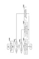
- the block diagram which shows the driving assistance system by this embodiment The functional block diagram of the LTC part in the driving assistance system of FIG. 1A.
- the flowchart which shows the process by a camera part. The schematic diagram explaining calculation of a curvature.
- the other schematic diagram explaining calculation of a curvature. The flowchart which shows the detection process of LTC starting SW.
- the flowchart which shows LTC processing. The flowchart which shows LTC processing.
- (1. Configuration) 1A includes a driving support device 10, a camera unit 20, an LTC (Lane Trace Control) activation switch (SW) 22, a vehicle speed setting device 24, a navigation device 26, a vehicle speed sensor 28, and the like. , An HMI (Human Machine Interface) unit 30, a steering system 40, a powertrain system 42, and a brake system 44.
- a vehicle equipped with the driving support system 2 is referred to as a host vehicle.
- the driving support device 10 is equipped with a computer having a CPU (central processing unit), a RAM (random access memory), a ROM (read-only memory), an input / output interface, etc., and the CPU is stored in the ROM. By executing various programs, it functions as the LTC unit 12, the lateral motion control unit 14, and the longitudinal motion control unit 16.
- the LTC unit 12 executes lane trace control that causes the host vehicle to travel on a travel path that is divided into left and right by a white line on which the host vehicle is currently traveling, based on image data captured by the camera unit 20.
- the lateral motion control unit 14 instructs the steering system 40 on the torque to drive the steering wheel based on the parameters and flags acquired from the LTC unit 12 in the lane trace control.
- the lateral movement control unit 14 commands the steering system 40 with a torque for driving the steering wheel, so that the host vehicle travels in the commanded lateral position on the travel path.
- the front-rear motion control unit 16 instructs the powertrain system 42 to drive the vehicle to travel based on the parameters and flags acquired from the LTC unit 12, and instructs the brake system 44 to apply the braking force. To do.
- the front-rear direction motion control unit 16 commands the powertrain system 42 to output a drive and commands the brake system 44 to apply a braking force, so that the host vehicle travels at the commanded vehicle speed set by the vehicle speed setting unit 24 in the lane trace control. To do.
- the vehicle speed setting device 24 is used when the host vehicle follows the preceding vehicle or when leaving the automobile exclusive road.
- the command vehicle speed is appropriately reduced regardless of the set vehicle speed.
- the camera unit 20 generates, for example, left and right white lines that define a travel path on which the host vehicle travels based on image data captured by a camera attached near the center of a mirror of a window shield in the vehicle interior of the host vehicle. Detection is based on the luminance difference between the white line and the road surface.
- the camera unit 20 calculates the curvature of the traveling road based on, for example, the coordinates of the left and right white lines detected as described later. Further, the camera unit 20 calculates the yaw angle of the host vehicle and the lateral position of the host vehicle with respect to the reference point of the travel path based on the image data.
- the LTC activation SW 22 is a lever switch attached to the center portion of the steering handle, and can select either the on or off position from the reference position by the driver's operation. When the driver selects on or off from the reference position of the LTC activation SW 22 and releases the hand, the LTC activation SW 22 returns from the on or off to the reference position.
- the LTC unit 12 determines that the driver has instructed activation of the lane trace control.
- the LTC unit 12 determines that the driver has commanded the end of the lane trace control.
- the vehicle speed setter 24 is used by a driver to input a command vehicle speed when the LTC unit 12 executes lane trace control by operating a touch panel or the like.
- the navigation device 26 guides the route to the destination based on the current position of the host vehicle and the destination of the host vehicle input from the touch panel or the like.
- the navigation device 26 receives a positioning signal from a positioning satellite such as a GPS satellite, and maps the position of the host vehicle based on map information stored in the map DB.
- the navigation device 26 acquires the passage of the ETC gate from the ETC device if it is a toll road, so that it can enter the vehicle-only road and only for the vehicle. The exit from the road is detected and transmitted to the LTC unit 12.
- ETC Electronic Toll Collection System: registered trademark
- the navigation device 26 detects entry into and exit from the automobile road based on the position of the own vehicle, and the LTC unit 12 You may send it.
- the HMI unit 30 notifies the driver of the execution state of the lane trace control according to an instruction from the LTC unit 12 using at least one of sound, image, and light.
- the steering system 40 drives the steering handle according to the torque commanded from the lateral motion control unit 14 and controls the lateral motion of the host vehicle.
- the powertrain system 42 controls the opening degree of the throttle device and the fuel injection amount according to the drive output commanded from the longitudinal motion control unit 16 as a drive source.
- the power supplied to the motor is controlled.
- the brake system 44 controls the actuator provided in the hydraulic circuit of the hydraulic brake according to the braking force commanded from the longitudinal motion control unit 16.
- the brake system 44 controls the power supplied to the motor in accordance with the braking force commanded from the front-rear direction motion control unit 16 and the braking force by the regenerative braking. May be generated.
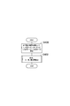
- step S400 of FIG. 2 the camera unit 20 detects a white line from the captured image data, and uses the positions of the white lines on both the left and right sides up to about 150 m ahead of the traveling direction as the boundary position of the traveling path on which the vehicle will travel. calculate.
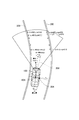
- the camera unit 20 uses, for example, the center of gravity 102 of the host vehicle 100 as the origin, the horizontal direction of the host vehicle 100 as the x axis, and the direction orthogonal to the x axis as the y axis. That is, the y axis represents the direction of the host vehicle 100. And the camera part 20 calculates the position of the white lines 200 and 202 on either side from the own vehicle 100 to about 150 m ahead.
- the camera unit 20 acquires the x-coordinate and y-coordinate of the position of the left white line 200 from (x_left [0], y_left [0]) to (x_left [n], y_left [n]). Further, the camera unit 20 acquires the x coordinate and the y coordinate of the position of the white line 202 on the right side from (x_right [0], y_right [0]) to (x_right [n], y_right [n]).
- the camera unit 20 sets the curvature (rho) of the traveling path of the host vehicle defined by the coordinate positions of the left and right white lines 200 and 202 calculated in step S400, for example, about 150 m ahead of the host vehicle 100. 15 are calculated every 10 m.
- the curvature (rho) of the travel path the curvature of one of the left and right white lines 200 and 202 may be calculated, or the curvature of the center line of the travel path passing through the center position 204 in the width direction of the travel path is calculated. Also good.
- the curvature of the travel path ahead of the host vehicle 100 in the travel direction is calculated as a physical quantity corresponding to the degree of curvature of the travel path ahead of the host vehicle 100 in the travel direction.
- the camera unit 20 sets the left and right boundary lines 220 and 222 so as to avoid the obstacle 300 instead of the left and right white lines 210 and 212.
- the x and y coordinates of the boundary lines 220 and 222 are calculated in the same manner as the white lines 210 and 212.
- the camera unit 20 travels the host vehicle defined by the coordinate positions of the left and right white lines 210 and 212 and the boundary lines 220 and 222 instead of the white lines 210 and 212 in the range where the boundary lines 220 and 222 are set.
- the curvature of the road is calculated every 10 m from the own vehicle 100 to about 150 m ahead.
- the camera unit 20 calculates the yaw angle and the lateral position of the host vehicle.
- the yaw angle (theta) of the host vehicle represents an angle formed by the y-axis that is the direction of the host vehicle and the tangent line 206 of the travel path at the center of gravity 102 of the host vehicle 100 as shown in FIG.
- the lateral position (yc) represents the distance from the center position 204 of the travel path passing through the center of gravity 102 of the host vehicle 100 to the center of gravity 102 of the host vehicle 100.
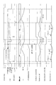
- step S410 of FIG. 5 when the driver turns on the LTC activation SW 22 (step S410: Yes), the LTC activation SW 22 turns on driver_apl_sw_flg and initializes the counter to 0 (step S412). If the driver_apl_sw_flg is on, it indicates that the driver has turned on the LTC start SW22 to instruct the start of lane trace control, and if off, the driver has turned off the LTC start SW22 and instructed the end of the lane trace control. It is a flag indicating that it has been done.
- step S410 When the driver turns off the LTC activation SW 22 instead of on (step S410: No, step S414: Yes), the LTC activation SW 22 turns off the driver_apl_sw_flg and initializes the counter to 0 (step S416).
- step S410 If the driver does not turn on or off the LTC activation SW 22 (step S410: No, step S414: No), the LTC activation SW 22 increments the counter by 1 (step S418), and the counter value is set to a predetermined constant (step S418). It is determined whether or not (CNT_TH) or more (step S420). Since the processing of FIG. 5 is executed at predetermined time intervals, whether or not the counter value is equal to or greater than a constant (CNT_TH) is determined by determining whether or not a predetermined time corresponding to the constant (CNT_TH) has elapsed. It represents.
- step S420: Yes the LTC activation SW 22 sets the driver_apl_sw_flg to neutral and sets the counter to 0 (step S422). Setting the driver_apl_sw_flg to neutral in step S422 indicates that the LTC activation SW 22 has not been operated either on or off and a predetermined time has elapsed.
- step S420: No the LTC activation SW 22 ends this process. That is, when the driver turns on the LTC activation SW 22, the driver_apl_sw_flg is kept on until the counter value becomes CNT_TH or more and a predetermined time elapses. When the driver turns off the LTC activation SW 22, the driver_apl_sw_flg continues to be turned off until the counter value becomes equal to or greater than CNT_TH and a predetermined time elapses.
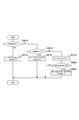
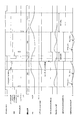
- step S430 of FIG. 6 the LTC unit 12 acquires driveway_state and rho from the camera unit 20, acquires driver_apl_sw_flg from the LTC activation SW 22, and acquires the HMI_state set by the LTC unit 12 itself.
- HMI_state represents the content that the HMI unit 30 informs the driver of the execution state of the lane trace control based on an instruction from the LTC unit 12.
- the notification contents of HMI_state are the following five types (1) to (5).
- the content of the HMI_state is notified by at least one of sound, image, and light using at least one of a speaker and a display.
- the initial value of HMI_state is NON_DISPLAY.
- LTC_ENABLE LTC executable
- LTC_CTRL LTC running
- LTC_DESABLE_WARNING LTC end notice
- LTC_HANDOVER Driver sovereignty to YN_DISP None of 2) to 5 indicates that there is no content for notifying the driver of the execution state of the lane trace control.
- LTC_ENABLE indicates that the host vehicle can enter the automobile road and execute the lane trace control, but the LTC activation SW 22 is not yet turned on.
- LTC_CTRL indicates that lane trace control is being executed.
- LTC_DESABLE_WARNING the conditions for ending the lane trace control after the own vehicle exits from the automobile-only road are satisfied, but the lane trace control is large and the lane trace control is large. It means that it is waiting.
- LTC_HANDOVER indicates that the lane trace control is finished and a process for transferring the sovereignty of the driving operation to the driver is started.
- step S432 Yes
- step S434 the LTC unit 12 sets the values of various parameters as follows (step S436).
- HMI_state LTC_ENABLE
- lateral_control_enable_flg off
- longitudinal_control_ref 0.
- step S434 As shown in FIG. 10 and FIG. 11, when the host vehicle enters the automobile exclusive road, the HMI_state is set from NON_DISPLAY to LTC_ENABLE in step S436, so the determination in step S434 becomes “No” in the next processing, and step The process proceeds to S438.
- Lateral_control_enable_flg indicates that the lateral movement of the vehicle is being controlled by steering control that drives the steering wheel in lane trace control, and if it is off, steering control that drives the steering wheel is stopped. Represents. Lateral_control_ref represents the command lateral position for the host vehicle.
- the center position 204 in the width direction of the travel path that is, the middle position between the white line 200 on the left side and the white line 202 on the right side is set as the command lateral position.
- the center position in the width direction of the travel path defined by the left boundary line 220 including the white lines 200 and 210 and the right boundary line 222 is set as the command lateral position.
- Longitudinal_control_enable_flg indicates that the vehicle speed control of the host vehicle is being executed by the powertrain system 42 and the brake system 44 in the lane trace control if it is on, and the vehicle speed control of the host vehicle is stopped if it is off.
- longitudinal_control_ref represents a command acceleration for the host vehicle for controlling the vehicle speed of the host vehicle to the command vehicle speed set by the vehicle speed setter 24.
- the LTC unit 12 sets the values of various parameters as shown in FIG. 10 and FIG. (Step S440).
- lateral_control_enable_flg If lateral_control_enable_flg is on, it means that the lateral movement control for controlling the lateral position of the host vehicle is executed by executing steering control for the steering wheel in the lane trace control, and if it is off, the lateral movement control is terminated. Represents.
- Longitudinal_control_enable_flg indicates that the vehicle motion of the host vehicle is controlled to the command vehicle speed set by the vehicle speed setting device 24 in the lane trace control if it is on, and the longitudinal motion control is terminated if it is off. Indicates to do.
- step S440 the LTC unit 12 calculates a command acceleration (longitudinal_control_ref) for the host vehicle based on the following equations (1) to (3) (step S440).
- diffV Vspd_ref ⁇ Vspd (1)
- diffV_int DiffV_int [n-1] + (diffV [n-1] + diffV) * TS / 2
- longitudinal_control_ref KP_LONG * diffV + KI_LONG * diffV_int ...
- diffV represents the difference between the command vehicle speed (Vspd_ref) and the actual vehicle speed (Vspd).
- diffV_int is obtained by adding the sum of the difference between the command vehicle speed and the actual vehicle speed in the time interval (TS) between the previous process and the current process to the sum of the difference between the command vehicle speed and the actual vehicle speed until the previous time. Value. That is, diffV_int represents the integration of the difference between the command vehicle speed up to this time and the actual vehicle speed.
- the LTC start SW 22 is operated to be turned off from the reference position while the host vehicle is traveling on the automobile exclusive road, or it is started to transfer the sovereignty of the driving operation to the driver.
- the LTC unit 12 sets the values of various parameters as follows (step S444).
- HMI_state When HMI_state is set to LTC_handover, it is notified by at least one of sound, image, and light that transfer of sovereignty of driving operation to the driver is started.
- the handover_timer measures the period for notifying that the transfer of the sovereignty of the driving operation to the driver is started.
- HOV_TH represents a period for informing that the transfer of the sovereignty of the driving operation to the driver is started.
- step S446 Yes
- step S450 of FIG. 7 the LTC unit 12 determines whether or not the conditions (1) to (3) described below are satisfied at the same time.
- max (rho) ⁇ RHO_TH If max (rho) ⁇ RHO_TH in step S450, the maximum value (max (rho)) of the curvature of the traveling path ahead of the traveling direction of the host vehicle is a predetermined value when the host vehicle leaves the automobile exclusive road. It represents that it is more than a certain RHO_TH.
- max (rho) is the maximum value of 15 curvatures calculated at intervals of 10 m on the traveling road ahead in the traveling direction of the host vehicle. As the curvature increases, the radius of curvature of the travel path decreases. Therefore, the curvature increases as the curvature increases.
- the above conditions (1) and (2) are satisfied, and the above condition (3) is established in which the degree of bending of the traveling road ahead of the own vehicle in the traveling direction after exiting the automobile exclusive road is greater than or equal to a predetermined value.
- the LTC unit 12 does not immediately transfer the sovereignty of the driving operation to the driver, but continues the lane trace control by executing the processes of steps S452 to S458 below.
- step S450 When the above conditions (1) to (3) are simultaneously satisfied (step S450: Yes), the LTC unit 12 sets HMI_state to LTC_DESABLE_WARNING and notifies the driver that the lane trace control is finished (step S452). . In this case, in addition to notifying the end of the lane trace control, the lane trace control will be ended soon, so that the driver may be notified of the driving operation such as “hold the steering wheel”.
- LTC unit 12 increments the LTC_shotdown_timer by 1 (step S452).
- LTC_shotdown_timer is a timer for measuring an elapsed time after the host vehicle leaves the automobile road.
- step S454 when the LTC_shotdown_timer becomes equal to or greater than SDT_TH (step S454: Yes), the LTC unit 12 has a predetermined elapsed time since the end of the lane trace control after the vehicle exited the automobile exclusive road. It is determined that SDT_TH, which is the time, has elapsed, LTC_HANDOVER is set in HMI_state, and LTC_shotdown_timer is initialized to 0 (step S456).
- step S458 when longitudinal_control_ref is set based on the above-described equations (1) to (3) in step S458, the host vehicle exits from the road for exclusive use of the car, so that regardless of the vehicle speed set by the driver using the vehicle speed setter 24.
- the command vehicle speed (Vspd_ref) is decelerated, for example, to the speed limit for passing through the ETC gate and the speed limit for the exit road until the vehicle enters the general road.
- step S450 after the own vehicle leaves the car-only road is “No” when rho ⁇ RHO_TH or when LTC_shotdown_timer ⁇ SDT_TH.
- the curve of the traveling path becomes smaller than a predetermined value before a predetermined time has elapsed after the own vehicle exits the automobile exclusive road, or as shown in FIG. This is when a predetermined time elapses after the vehicle leaves the automobile road.
- the LTC activation SW 22 is not moved from the reference position.
- the process of transferring the sovereignty of the driving operation to the driver is immediately executed.
- driver_apl_sw_flg off, the driver is instructing transfer of the sovereignty of the driving operation.
- HMI_state LTC_CTRL
- step S460 LTC_HANDOVER
- HMI_state LTC_HANDOVER
- driver_apl_sw_flg off or HMI_state is other than NON_DISPLAY (step S460: Yes)
- the LTC unit 12 sets values of various parameters in the same manner as step S444 in FIG. 6 (step S462).
- step S ⁇ b> 470 of FIG. 8 the lateral motion control unit 14 acquires lateral_control_enable_flg, lateral_control_ref, max (rho), metadata, yc from the LTC unit 12.
- step S476 Yes
- the lateral motion control unit 14 determines that the lane trace control is being executed, and determines the steering wheel based on the following expressions (4) to (6).
- a torque control command value (handle_trq_ref) for executing the steering control for is calculated (step S478).
- diffy lateral_control_ref-yc ...
- diffy represents the difference between the command lateral position and the lateral position of the center of gravity 102 of the host vehicle 100.
- lateral_control_ref 0.
- diffy_int is the sum of the difference between the previous command lateral position and the actual lateral position, and the difference between the command lateral position and the actual lateral position in the time interval (TS) between the previous and current processing. It is a value obtained by adding the integration of the difference. That is, diffy_int represents the integration of the difference between the commanded lateral position up to this time and the actual lateral position.
- step S480: Yes) the lateral motion control unit 14 determines that the end of the lane trace control has been commanded, and controls the sovereignty of the driving operation. The process to transfer to the driver is started.
- step S482 the lateral motion control unit 14 sets the smoothing rate (K_NAMASI ⁇ 1) of the torque control command value for executing the steering control smoothing process for the steering wheel, and max (rho) as the parameter. Is calculated from the map by the following equation (7).
- K_NAMASI MAP (max (rho)) (7) It is desirable that the greater the maximum value of the travel path curvature, that is, the greater the maximum value of the travel path bend, the smaller the smoothing rate and the lower the torque control command value. As a result, the amount of driving operation of the steering wheel by the driver can be increased gradually, and the burden of driving operation by the driver can be increased gradually.
- handle_trq_ref handle_trq_ref * K_NAMES (8) Since K_NAMASI ⁇ 1, every time step S484 is executed, the absolute value of handle_trq_ref calculated in step S484 becomes smaller as indicated by the period of the annealing process in FIGS.
- step S486 When the absolute value of handle_trq_ref becomes equal to or less than the predetermined value HTRQ_TH (step S486: Yes), the lateral motion control unit 14 sets handle_trq_ref to 0 and ends the annealing process as shown in FIGS. (Step S488). Thereby, when the torque command control value becomes equal to or lower than HTRQ_TH, the annealing process can be ended.
- handle_trq_ref While the absolute value of handle_trq_ref is larger than HTRQ_TH (step S486: No), the lateral motion control unit 14 continues the annealing process.
- step S ⁇ b> 490 of FIG. 9 the longitudinal motion control unit 16 acquires longitudinal_control_enable_flg and longitudinal_control_ref from the LTC unit 12.
- longitudinal_control_enable_flg ON, that is, when lane trace control is being performed (step S492: Yes)
- the longitudinal motion control unit 16 determines whether or not longitudinal_control_ref ⁇ 0 (step S494).
- step S494 Yes
- the longitudinal motion control unit 16 calculates the drive output (powertrain_control_ref) commanded to the powertrain system 42 from the following equation (9). (Step S496).
- powertrain_control_ref longitudinal_control_ref * VEHICLE_MASS ... (9)
- the longitudinal motion control unit 16 sets the braking force (break_control_ref) commanded to the brake system 44 to 0 (step S496).
- step S494 When longitudinal_control_ref ⁇ 0 (step S494: No), that is, when the commanded acceleration is negative, the longitudinal motion control unit 16 calculates the braking force (break_control_ref) commanded to the brake system 44 from the following formula (10) (step 10). S498).
- break_control_ref longitudinal_control_ref * VEHICLE_MASS (10)
- the longitudinal motion control unit 16 sets the drive output (powertrain_control_ref) commanded to the powertrain system 42 to 0 (step S498).
- step S492 No
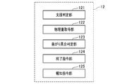
- FIG. 1B shows functional blocks representing the functions of the LTC unit 2.
- the LTC unit 2 includes functional blocks such as a support determination unit 121, a physical quantity acquisition unit 122, a bending state determination unit 123, an end command unit 124, and a notification command unit 125.
- the support determination unit 121 is a functional block that executes Step S432, and is configured to determine whether or not a predetermined condition for the driving support control unit 17 to end the driving support control is satisfied. For example, the support determination unit 121 may determine that the predetermined condition is satisfied when the host vehicle exits the automobile-only road.
- the physical quantity acquisition unit 122 is a functional block that executes Step S450, and is configured to acquire a physical quantity corresponding to the degree of bending of the travel path on which the host vehicle travels.
- the bending state determination unit 123 is also a functional block that executes step S450.
- the support determination unit 121 determines that a predetermined condition is satisfied, the bending state indicated by the physical quantity acquired by the physical quantity acquisition unit 122 is greater than a predetermined size. It is determined whether or not it is small.
- the physical quantity acquisition unit 122 acquires the curvature of the traveling road as the physical quantity, and the bending condition determination unit 123 determines whether the bending condition is smaller than the predetermined magnitude depending on whether the curvature is smaller than a predetermined value.
- the physical quantity acquisition unit 122 may acquire, as the curvature of the travel path, the curvature of the travel path ahead of the host vehicle in the travel direction based on, for example, map information. Alternatively or additionally, the physical quantity acquisition unit 122 acquires a steering angle, and the bending condition determination unit 123 determines whether the bending condition is smaller than the predetermined magnitude depending on whether the steering angle is smaller than a predetermined value. May be configured to determine.
- the end command unit 124 is a functional block that executes Step S462.
- the bend state determination unit determines that the bend state is smaller than the predetermined size
- the end command unit 124 instructs the drive support control unit to end the drive support control.
- the end command unit 124 is a functional block that further executes steps S454 and S456.
- steps S454 and S456 When a predetermined time elapses after the predetermined condition is satisfied, the driving support is performed even if the bending degree is equal to or greater than the predetermined magnitude.
- the control unit is instructed to end the driving support control.
- the notification command unit 125 is a functional block that executes Step S452, and is configured to notify the end of the driving support control before the end command unit instructs the driving support control unit to end the driving support control. Is done.
- the lateral motion control unit 14 that executes steps S470 to S488 and the longitudinal motion control unit 16 that executes steps S490 to S500 perform at least a part of the driving operation by the driver.
- a driving support control unit 17 that executes driving support control to be supported is configured. As shown in steps S482 to S486, the driving support control unit 17 is configured to gradually decrease the control amount by the driving support control when the end command unit 124 instructs the end of the driving support control. At this time, the driving support control unit 17 adjusts the degree of decrease in the control amount according to the physical quantity, for example, the vehicle speed of the host vehicle.
- the driving support control unit 17 performs steps S470 to S488 through the lateral motion control unit 14 to support steering control.
- the driving support control unit 17 performs steps S490 to S500 through the longitudinal motion control unit 16 to support vehicle speed control.
- the curvature of the travel path is used as a physical quantity corresponding to the degree of bending of the travel path of the host vehicle.
- a steering angle, a lateral acceleration of the host vehicle detected by an acceleration sensor, or the like may be used as a physical quantity corresponding to the curve of the traveling path of the host vehicle. It can be determined that the greater the steering angle, the greater the curve of the travel path, and the greater the lateral acceleration, the greater the curve of the travel path.
- the lateral motion control unit 14 acquires the steering angle from the steering system 40 as shown in FIG. 1A.
- the driving support device 10 may acquire the curvature of the travel path from the map information of the map DB provided in the navigation device 26 shown in FIG. 1A instead of the image data captured by the camera unit 20.
- the smoothing rate of the torque control command value for driving the steering wheel may be variably set according to the vehicle speed.
- the degree of decrease in torque control command value may be reduced by decreasing the smoothing rate as the vehicle speed increases.
- the lane trace control is ended even if the curvature is equal to or greater than the predetermined value.
- the predetermined time may be set longer as the curvature increases in a range where the curvature is equal to or greater than a predetermined value.
- the lane trace control is executed as the driving support control when the host vehicle enters the automobile road and the driver turns on the LTC activation SW 22.
- the driving support control may be executed when the LTC activation SW 22 is turned on regardless of whether or not the own vehicle has entered the automobile road.
- both the vehicle speed control and the steering control of the host vehicle are controlled as the driving support control.
- only one of the vehicle speed control or the steering control of the host vehicle may be controlled as the driving support control.
- the condition for terminating the lane trace control as the driving support control is that the host vehicle exits from the automobile-only road.
- the driver turns off the LTC start SW 22 during the driving support control or whether the driver operates the steering handle while holding the steering handle, regardless of whether or not the own vehicle exits from the automobile road.
- the driving support control may be terminated.
- a driving support system 2 including the driving support device 10 as a constituent element, a driving support program for causing a computer to function as the driving support device 10, and the driving support program are recorded.
- the present invention can also be realized in various forms such as a recording medium and a driving support method.
Landscapes
- Engineering & Computer Science (AREA)
- Transportation (AREA)
- Mechanical Engineering (AREA)
- Automation & Control Theory (AREA)
- Physics & Mathematics (AREA)
- Mathematical Physics (AREA)
- Chemical & Material Sciences (AREA)
- Combustion & Propulsion (AREA)
- Human Computer Interaction (AREA)
- General Physics & Mathematics (AREA)
- Theoretical Computer Science (AREA)
- Steering Control In Accordance With Driving Conditions (AREA)
- Control Of Driving Devices And Active Controlling Of Vehicle (AREA)
- Traffic Control Systems (AREA)
Abstract
A driving assist control unit (17, 14, 16) of this driving assist device (10) executes driving assist control for assisting at least a part of a driving operation performed by the driver. An assist determination part (12, 121) determines whether or not predetermined conditions for ending the driving assist control are met. A physical quantity acquisition part (12, 122) acquires a physical quantity that corresponds to a degree of curvature of a traveling path along which the host vehicle is traveling. When the conditions for ending the driving assist control are met, a curvature degree determination part (12, 123) determines whether or not the curvature degree indicated by the physical quantity acquired by the physical quantity acquisition part is smaller than a predetermined degree. When the curvature degree determination part has determined that the curvature degree is smaller than the predetermined degree, an end instruction part (12, 124) instructs the driving assist control unit to end the driving assist control.
Description
本出願は、2015年6月4日に出願された日本出願番号2015-114163号に基づくもので、ここにその記載内容を援用する。
This application is based on Japanese Application No. 2015-114163 filed on June 4, 2015, the contents of which are incorporated herein by reference.
本発明は、ドライバによる運転操作の少なくとも一部を支援する技術に関する。
The present invention relates to a technology that supports at least a part of a driving operation by a driver.
ドライバによる運転操作の少なくとも一部を支援する運転支援制御の技術が種々提案されている。例えば、特許文献1には、運転支援制御を実行するための所定の条件が成立したことを運転支援システムがドライバに報知し、ドライバがハンドルから手を離すと運転支援システムが運転支援制御を実行する技術が開示されている。
Various driving support control technologies that support at least part of driving operations by drivers have been proposed. For example, in Patent Document 1, the driving support system notifies the driver that a predetermined condition for executing driving support control is established, and the driving support system executes driving support control when the driver releases his handle. Techniques to do this are disclosed.
特許文献1に開示されている技術では、運転支援制御中にドライバがハンドルの特定の場所に接触したことを検出すると、運転支援制御を終了する条件が成立したと判断し、運転支援制御を終了してドライバによる運転操作に移行する。
In the technique disclosed in Patent Literature 1, when it is detected that the driver has touched a specific position on the steering wheel during the driving support control, it is determined that the condition for ending the driving support control is satisfied, and the driving support control is ended. Then, it shifts to the driving operation by the driver.
しかしながら、運転支援制御を実行中に運転支援制御を終了する条件が成立し運転支援制御からドライバによる運転操作に移行するときに、車両が曲がり具合の大きい走行路を走行することがある。この場合、運転支援制御からドライバによる運転操作にすぐに移行すると、曲がり具合の大きい走行路を運転する運転操作の困難な状況にドライバが急に対応することになるので、ドライバにとって運転操作が大きな負担になる。
However, when the condition for ending the driving support control is satisfied while the driving support control is being executed and the driving operation is shifted from the driving support control to the driving operation by the driver, the vehicle may travel on a road with a large degree of bending. In this case, if the driver immediately shifts from the driving support control to the driving operation by the driver, the driver suddenly responds to the difficult situation of the driving operation to drive the driving road with a large degree of bending. It will be a burden.
本発明は上記に鑑みてなされたものであり、運転支援制御を終了してドライバによる運転操作に移行する条件が成立するときに、走行路の曲がり具合に応じてドライバによる運転操作の負担を極力低減する技術を提供することを目的とする。
The present invention has been made in view of the above, and when the condition for ending the driving support control and shifting to the driving operation by the driver is satisfied, the burden of the driving operation by the driver is reduced as much as possible according to the bending condition of the traveling path. It aims at providing the technology to reduce.
本発明の一態様による運転支援装置は、運転支援制御部と、支援判定部と、物理量取得部と、曲がり具合判定部と、終了指令部と、を備えている。
運転支援制御部は、ドライバによる運転操作の少なくとも一部を支援する運転支援制御を実行する。支援判定部は、運転支援制御部が運転支援制御を終了する所定条件が成立しているか否かを判定する。物理量取得部は、自車両が走行する走行路の曲がり具合に対応する物理量を取得する。 A driving support apparatus according to an aspect of the present invention includes a driving support control unit, a support determination unit, a physical quantity acquisition unit, a bending condition determination unit, and an end command unit.
The driving support control unit executes driving support control that supports at least a part of the driving operation by the driver. The support determination unit determines whether or not a predetermined condition for the driving support control unit to end the driving support control is satisfied. The physical quantity acquisition unit acquires a physical quantity corresponding to the degree of bending of the travel path on which the host vehicle travels.
曲がり具合判定部は、運転支援制御を終了する所定条件が成立していると支援判定部が判定すると、物理量取得部が取得する物理量が示す曲がり具合が所定の大きさより小さいか否かを判定する。終了指令部は、曲がり具合が所定の大きさより小さいと曲がり具合判定部が判定すると、運転支援制御部に運転支援制御の終了を指令する。
When the support determination unit determines that the predetermined condition for ending the driving support control is satisfied, the bend state determination unit determines whether the bend state indicated by the physical quantity acquired by the physical amount acquisition unit is smaller than a predetermined size. . When the bend state determination unit determines that the bend state is smaller than a predetermined size, the end command unit instructs the drive support control unit to end the drive support control.
この構成によれば、運転支援制御を終了する所定条件が成立しても、自車両が走行する走行路の曲がり具合が所定の大きさ以上の場合は運転支援制御を継続する。これにより、曲がり具合の大きい走行路を運転する運転操作の困難な状況にドライバが急に対応することを避けることができるので、ドライバによる運転操作の負担を極力低減できる。
According to this configuration, even if the predetermined condition for ending the driving support control is satisfied, the driving support control is continued when the degree of bending of the travel path on which the host vehicle travels is a predetermined magnitude or more. As a result, it is possible to prevent the driver from suddenly responding to a difficult situation of driving operation for driving on a road with a large degree of bending, so that the burden of driving operation by the driver can be reduced as much as possible.
以下、本発明の実施形態を、添付図面を参照しながら、より詳細に説明する。しかし、本発明は、多くの異なる形態で実施されてもよく、本明細書で説明される実施形態に限定されると解釈されるべきではない。むしろ、これらの実施形態は、この発明の開示を徹底的でかつ完全にし、本発明の範囲を当業者に完全に伝えるために、提供される。尚、類似の符号は、図面全体にわたって類似の構成要素を示す。
Hereinafter, embodiments of the present invention will be described in more detail with reference to the accompanying drawings. However, the present invention may be implemented in many different forms and should not be construed as limited to the embodiments set forth herein. Rather, these embodiments are provided so that this disclosure will be thorough and complete, and will fully convey the scope of the invention to those skilled in the art. Note that similar reference numbers indicate similar components throughout the drawings.
(1.構成)
図1Aに示す運転支援システム2は、運転支援装置10と、カメラ部20と、LTC(Lane Trace Control)起動スイッチ(SW)22と、車速設定器24と、ナビゲーション装置26と、車速センサ28と、HMI(Human Machine Interface)部30と、ステアリングシステム40と、パワートレインシステム42と、ブレーキシステム44とを備えている。以下の記述において、運転支援システム2を搭載した車両を自車両と言う。 (1. Configuration)
1A includes adriving support device 10, a camera unit 20, an LTC (Lane Trace Control) activation switch (SW) 22, a vehicle speed setting device 24, a navigation device 26, a vehicle speed sensor 28, and the like. , An HMI (Human Machine Interface) unit 30, a steering system 40, a powertrain system 42, and a brake system 44. In the following description, a vehicle equipped with the driving support system 2 is referred to as a host vehicle.
図1Aに示す運転支援システム2は、運転支援装置10と、カメラ部20と、LTC(Lane Trace Control)起動スイッチ(SW)22と、車速設定器24と、ナビゲーション装置26と、車速センサ28と、HMI(Human Machine Interface)部30と、ステアリングシステム40と、パワートレインシステム42と、ブレーキシステム44とを備えている。以下の記述において、運転支援システム2を搭載した車両を自車両と言う。 (1. Configuration)
1A includes a
運転支援装置10は、CPU(central processing unit)、RAM(random access memory)、ROM(read-only memory)、入出力インタフェース等を備えるコンピュータを搭載しており、CPUが、ROMに格納されている各種プログラムを実行することで、LTC部12と、横方向運動制御部14と、前後方向運動制御部16として機能する。
The driving support device 10 is equipped with a computer having a CPU (central processing unit), a RAM (random access memory), a ROM (read-only memory), an input / output interface, etc., and the CPU is stored in the ROM. By executing various programs, it functions as the LTC unit 12, the lateral motion control unit 14, and the longitudinal motion control unit 16.
LTC部12は、カメラ部20が撮像する画像データに基づいて、自車両が現在走行中の白線で左右を区切られた走行路内で自車両を走行させるレーントレース制御を実行する。
The LTC unit 12 executes lane trace control that causes the host vehicle to travel on a travel path that is divided into left and right by a white line on which the host vehicle is currently traveling, based on image data captured by the camera unit 20.
横方向運動制御部14は、レーントレース制御において、LTC部12から取得するパラメータおよびフラグに基づいて、ステアリングハンドルを駆動するトルクをステアリングシステム40に指令する。レーントレース制御において、横方向運動制御部14がステアリングハンドルを駆動するトルクをステアリングシステム40に指令することにより、自車両は走行路において指令横位置を走行する。
The lateral motion control unit 14 instructs the steering system 40 on the torque to drive the steering wheel based on the parameters and flags acquired from the LTC unit 12 in the lane trace control. In the lane trace control, the lateral movement control unit 14 commands the steering system 40 with a torque for driving the steering wheel, so that the host vehicle travels in the commanded lateral position on the travel path.
前後方向運動制御部16は、レーントレース制御において、LTC部12から取得するパラメータおよびフラグに基づいて、パワートレインシステム42に自車両を走行させる駆動出力を指令し、ブレーキシステム44に制動力を指令する。前後方向運動制御部16がパワートレインシステム42に駆動出力を指令し、ブレーキシステム44に制動力を指令することにより、自車両は、レーントレース制御において車速設定器24により設定される指令車速で走行する。
In the lane trace control, the front-rear motion control unit 16 instructs the powertrain system 42 to drive the vehicle to travel based on the parameters and flags acquired from the LTC unit 12, and instructs the brake system 44 to apply the braking force. To do. The front-rear direction motion control unit 16 commands the powertrain system 42 to output a drive and commands the brake system 44 to apply a braking force, so that the host vehicle travels at the commanded vehicle speed set by the vehicle speed setting unit 24 in the lane trace control. To do.
尚、レーントレース制御において車速設定器24により指令車速が設定されていても、前方車両に追随して自車両が走行する場合、あるいは自動車専用道路から退出する場合等においては、車速設定器24により設定されている車速に関わらず指令車速は適宜減速される。
Even if the command vehicle speed is set by the vehicle speed setting device 24 in the lane trace control, the vehicle speed setting device 24 is used when the host vehicle follows the preceding vehicle or when leaving the automobile exclusive road. The command vehicle speed is appropriately reduced regardless of the set vehicle speed.
カメラ部20は、例えば自車両の車室内のウィンドウシールドのミラーの中央付近に取り付けられているカメラが撮像する画像データに基づいて、自車両が走行する走行路を規定する左右の白線を、例えば白線と路面との輝度差に基づいて検出する。カメラ部20は、例えば後述するように検出した左右の白線の座標に基づいて走行路の曲率を算出する。さらに、カメラ部20は、自車両のヨー角と走行路の基準点に対する自車両の横位置等も画像データに基づいて算出する。
For example, the camera unit 20 generates, for example, left and right white lines that define a travel path on which the host vehicle travels based on image data captured by a camera attached near the center of a mirror of a window shield in the vehicle interior of the host vehicle. Detection is based on the luminance difference between the white line and the road surface. The camera unit 20 calculates the curvature of the traveling road based on, for example, the coordinates of the left and right white lines detected as described later. Further, the camera unit 20 calculates the yaw angle of the host vehicle and the lateral position of the host vehicle with respect to the reference point of the travel path based on the image data.
LTC起動SW22は、ステアリングハンドルの中央部に取り付けられたレバースイッチであり、ドライバの操作により基準位置からオンまたはオフのいずれかの位置を選択できる。ドライバがLTC起動SW22の基準位置からオンまたはオフを選択して手を離すと、オンまたはオフから基準位置までLTC起動SW22は戻る。
The LTC activation SW 22 is a lever switch attached to the center portion of the steering handle, and can select either the on or off position from the reference position by the driver's operation. When the driver selects on or off from the reference position of the LTC activation SW 22 and releases the hand, the LTC activation SW 22 returns from the on or off to the reference position.
ドライバがLTC起動SW22をオンにすると、LTC部12は、ドライバがレーントレース制御の起動を指令したと判断する。ドライバがLTC起動SW22をオフにすると、LTC部12は、ドライバがレーントレース制御の終了を指令したと判断する。
When the driver turns on the LTC activation SW 22, the LTC unit 12 determines that the driver has instructed activation of the lane trace control. When the driver turns off the LTC activation SW 22, the LTC unit 12 determines that the driver has commanded the end of the lane trace control.
車速設定器24は、LTC部12がレーントレース制御を実行するときの指令車速をドライバがタッチパネル等を操作して入力するものである。
ナビゲーション装置26は、自車両の現在位置とタッチパネル等から入力される自車両の目的地とに基づき、目的地までの経路を案内する。ナビゲーション装置26は、GPS衛星等の測位衛星から測位信号を受信して、自車両の位置を地図DBに記憶されている地図情報に基づいてマッピングする。 Thevehicle speed setter 24 is used by a driver to input a command vehicle speed when the LTC unit 12 executes lane trace control by operating a touch panel or the like.
Thenavigation device 26 guides the route to the destination based on the current position of the host vehicle and the destination of the host vehicle input from the touch panel or the like. The navigation device 26 receives a positioning signal from a positioning satellite such as a GPS satellite, and maps the position of the host vehicle based on map information stored in the map DB.
ナビゲーション装置26は、自車両の現在位置とタッチパネル等から入力される自車両の目的地とに基づき、目的地までの経路を案内する。ナビゲーション装置26は、GPS衛星等の測位衛星から測位信号を受信して、自車両の位置を地図DBに記憶されている地図情報に基づいてマッピングする。 The
The
ETC(Electronic Toll Collection System:登録商標)装置を搭載している場合、ナビゲーション装置26は、有料道路であればETCゲートの通過をETC装置から取得することにより、自動車専用道路への進入および自動車専用道路からの退出を検出し、LTC部12に送信する。
When an ETC (Electronic Toll Collection System: registered trademark) device is installed, the navigation device 26 acquires the passage of the ETC gate from the ETC device if it is a toll road, so that it can enter the vehicle-only road and only for the vehicle. The exit from the road is detected and transmitted to the LTC unit 12.
ETC装置を搭載していないか、あるいは無料の自動車専用道路の場合、ナビゲーション装置26は、自車位置に基づいて自動車専用道路への進入および自動車専用道路からの退出を検出し、LTC部12に送信してもよい。
In the case where the ETC device is not installed or the road is free of charge, the navigation device 26 detects entry into and exit from the automobile road based on the position of the own vehicle, and the LTC unit 12 You may send it.
ナビゲーション装置26は、自車両が自動車専用道路に進入しているか退出しているかを、driveway_stateで表わす。driveway_state=1であれば自動車専用道路に進入している状態を表わし、driveway_state=0であれば自動車専用道路から退出している状態を表わす。
The navigation device 26 indicates by driveway_state whether the vehicle is entering or leaving the car road. If driveway_state = 1, it represents a state where the vehicle is entering the exclusive road, and if driveway_state = 0, it represents a state where the vehicle is leaving the exclusive road.
HMI部30は、音と画像と光との少なくともいずれかを使用して、LTC部12からの指示に従ってドライバにレーントレース制御の実行状態を報知する。
The HMI unit 30 notifies the driver of the execution state of the lane trace control according to an instruction from the LTC unit 12 using at least one of sound, image, and light.
ステアリングシステム40は、横方向運動制御部14から指令されるトルクにしたがってステアリングハンドルを駆動し、自車両の横方向の運動を制御する。
The steering system 40 drives the steering handle according to the torque commanded from the lateral motion control unit 14 and controls the lateral motion of the host vehicle.
パワートレインシステム42は、前後方向運動制御部16から指令される駆動出力にしたがって、駆動源として内燃機関を搭載している場合にはスロットル装置の開度および燃料噴射量を制御し、駆動源としてモータを搭載している場合にはモータへの供給電力を制御する。
In the case where an internal combustion engine is mounted as a drive source, the powertrain system 42 controls the opening degree of the throttle device and the fuel injection amount according to the drive output commanded from the longitudinal motion control unit 16 as a drive source. When a motor is installed, the power supplied to the motor is controlled.
ブレーキシステム44は、前後方向運動制御部16から指令される制動力にしたがって、油圧式ブレーキの液圧回路に設けられたアクチュエータを制御する。自車両が駆動源としてモータを搭載している場合には、ブレーキシステム44は、前後方向運動制御部16から指令される制動力にしたがって、モータへの供給電力を制御して回生ブレーキによる制動力を生成してもよい。
The brake system 44 controls the actuator provided in the hydraulic circuit of the hydraulic brake according to the braking force commanded from the longitudinal motion control unit 16. When the host vehicle is equipped with a motor as a drive source, the brake system 44 controls the power supplied to the motor in accordance with the braking force commanded from the front-rear direction motion control unit 16 and the braking force by the regenerative braking. May be generated.
(2.処理)
以下、運転支援システム2が実行する処理について説明する。図2、図5~図9のフローチャートは所定時間間隔で常時実行される。 (2. Processing)
Hereinafter, the process which thedriving assistance system 2 performs is demonstrated. The flowcharts of FIGS. 2 and 5 to 9 are always executed at predetermined time intervals.
以下、運転支援システム2が実行する処理について説明する。図2、図5~図9のフローチャートは所定時間間隔で常時実行される。 (2. Processing)
Hereinafter, the process which the
(2-1.カメラ部20の処理)
カメラ部20が実行する処理について説明する。図2のステップS400において、カメラ部20は撮像した画像データから白線を検出し、自車両がこれから走行する走行路の境界位置として、走行方向前方の150m程度先までの左右両側の白線の位置を算出する。 (2-1. Processing of Camera Unit 20)
Processing executed by thecamera unit 20 will be described. In step S400 of FIG. 2, the camera unit 20 detects a white line from the captured image data, and uses the positions of the white lines on both the left and right sides up to about 150 m ahead of the traveling direction as the boundary position of the traveling path on which the vehicle will travel. calculate.
カメラ部20が実行する処理について説明する。図2のステップS400において、カメラ部20は撮像した画像データから白線を検出し、自車両がこれから走行する走行路の境界位置として、走行方向前方の150m程度先までの左右両側の白線の位置を算出する。 (2-1. Processing of Camera Unit 20)
Processing executed by the
図3に示すように、カメラ部20は、例えば自車両100の重心102を原点とし、自車両100の横幅方向をx軸、x軸と直交する方向をy軸とする。つまり、y軸は自車両100の向きを表わしている。そして、カメラ部20は、左右の白線200、202の位置を例えば自車両100から150m程度先まで算出する。
As shown in FIG. 3, the camera unit 20 uses, for example, the center of gravity 102 of the host vehicle 100 as the origin, the horizontal direction of the host vehicle 100 as the x axis, and the direction orthogonal to the x axis as the y axis. That is, the y axis represents the direction of the host vehicle 100. And the camera part 20 calculates the position of the white lines 200 and 202 on either side from the own vehicle 100 to about 150 m ahead.
カメラ部20は、左側の白線200の位置のx座標およびy座標を、(x_left[0]、y_left[0])から(x_left[n]、y_left[n])まで取得する。さらに、カメラ部20は、右側の白線202の位置のx座標およびy座標を、(x_right[0]、y_right[0])から(x_right[n]、y_right[n])まで取得する。
The camera unit 20 acquires the x-coordinate and y-coordinate of the position of the left white line 200 from (x_left [0], y_left [0]) to (x_left [n], y_left [n]). Further, the camera unit 20 acquires the x coordinate and the y coordinate of the position of the white line 202 on the right side from (x_right [0], y_right [0]) to (x_right [n], y_right [n]).
そして、ステップS402において、カメラ部20は、ステップS400で算出した左右両側の白線200、202の座標位置で規定される自車両の走行路の曲率(rho)を、例えば自車両100から150m程度先まで10m間隔毎に15個算出する。走行路の曲率(rho)として、左右の白線200、202のいずれかの曲率を算出してもよいし、走行路の幅方向の中央位置204を通る走行路の中央線の曲率を算出してもよい。
In step S402, the camera unit 20 sets the curvature (rho) of the traveling path of the host vehicle defined by the coordinate positions of the left and right white lines 200 and 202 calculated in step S400, for example, about 150 m ahead of the host vehicle 100. 15 are calculated every 10 m. As the curvature (rho) of the travel path, the curvature of one of the left and right white lines 200 and 202 may be calculated, or the curvature of the center line of the travel path passing through the center position 204 in the width direction of the travel path is calculated. Also good.
本実施形態では、自車両100の走行方向前方の走行路の曲がり具合に対応する物理量として、自車両100の走行方向前方の走行路の曲率を算出する。
In the present embodiment, the curvature of the travel path ahead of the host vehicle 100 in the travel direction is calculated as a physical quantity corresponding to the degree of curvature of the travel path ahead of the host vehicle 100 in the travel direction.
図4に示すように、自車両100の前方に障害物300が存在する場合、カメラ部20は、左右の白線210、212に代えて障害物300を避けるように左右の境界線220、222を設定し、境界線220、222のx座標およびy座標を白線210、212と同様に算出する。
As shown in FIG. 4, when the obstacle 300 exists in front of the host vehicle 100, the camera unit 20 sets the left and right boundary lines 220 and 222 so as to avoid the obstacle 300 instead of the left and right white lines 210 and 212. The x and y coordinates of the boundary lines 220 and 222 are calculated in the same manner as the white lines 210 and 212.
そして、カメラ部20は左右の白線210、212と、境界線220、222が設定されている範囲では白線210、212に代えて境界線220、222との座標位置で規定される自車両の走行路の曲率を、自車両100から150m程度先まで10m間隔毎に算出する。
The camera unit 20 travels the host vehicle defined by the coordinate positions of the left and right white lines 210 and 212 and the boundary lines 220 and 222 instead of the white lines 210 and 212 in the range where the boundary lines 220 and 222 are set. The curvature of the road is calculated every 10 m from the own vehicle 100 to about 150 m ahead.
さらに、ステップS402において、カメラ部20は、自車両のヨー角と横位置とを算出する。自車両のヨー角(theta)は、図3に示すように自車両の向きであるy軸と、自車両100の重心102における走行路の接線206とが形成する角度を表わしている。横位置(yc)は、自車両100の重心102を通る走行路の中央位置204から自車両100の重心102までの距離を表わしている。
Furthermore, in step S402, the camera unit 20 calculates the yaw angle and the lateral position of the host vehicle. The yaw angle (theta) of the host vehicle represents an angle formed by the y-axis that is the direction of the host vehicle and the tangent line 206 of the travel path at the center of gravity 102 of the host vehicle 100 as shown in FIG. The lateral position (yc) represents the distance from the center position 204 of the travel path passing through the center of gravity 102 of the host vehicle 100 to the center of gravity 102 of the host vehicle 100.
(2-2.LTC起動SW22の検出処理)
ドライバによるLTC起動SW22の操作を検出する処理について説明する。
図5のステップS410において、ドライバがLTC起動SW22をオンにすると(ステップS410:Yes)、LTC起動SW22はdriver_apl_sw_flgをオンにし、counterを0にして初期化する(ステップS412)。driver_apl_sw_flgは、オンであれば、ドライバがLTC起動SW22をオンにしてレーントレース制御の起動を指令したことを示し、オフであれば、ドライバがLTC起動SW22をオフにしてレーントレース制御の終了を指令したことを示すフラグである。 (2-2. Detection process of LTC start SW22)
Processing for detecting the operation of theLTC activation SW 22 by the driver will be described.
In step S410 of FIG. 5, when the driver turns on the LTC activation SW 22 (step S410: Yes), theLTC activation SW 22 turns on driver_apl_sw_flg and initializes the counter to 0 (step S412). If the driver_apl_sw_flg is on, it indicates that the driver has turned on the LTC start SW22 to instruct the start of lane trace control, and if off, the driver has turned off the LTC start SW22 and instructed the end of the lane trace control. It is a flag indicating that it has been done.
ドライバによるLTC起動SW22の操作を検出する処理について説明する。
図5のステップS410において、ドライバがLTC起動SW22をオンにすると(ステップS410:Yes)、LTC起動SW22はdriver_apl_sw_flgをオンにし、counterを0にして初期化する(ステップS412)。driver_apl_sw_flgは、オンであれば、ドライバがLTC起動SW22をオンにしてレーントレース制御の起動を指令したことを示し、オフであれば、ドライバがLTC起動SW22をオフにしてレーントレース制御の終了を指令したことを示すフラグである。 (2-2. Detection process of LTC start SW22)
Processing for detecting the operation of the
In step S410 of FIG. 5, when the driver turns on the LTC activation SW 22 (step S410: Yes), the
ドライバがLTC起動SW22をオンではなくオフにすると(ステップS410:No、ステップS414:Yes)、LTC起動SW22は、driver_apl_sw_flgをオフにし、counterを0にして初期化する(ステップS416)。
When the driver turns off the LTC activation SW 22 instead of on (step S410: No, step S414: Yes), the LTC activation SW 22 turns off the driver_apl_sw_flg and initializes the counter to 0 (step S416).
ドライバがLTC起動SW22をオンにせずオフにもしないと(ステップS410:No、ステップS414:No)、LTC起動SW22は、counterを+1し(ステップS418)、counterの値が予め設定された定数(CNT_TH)以上であるか否かを判定する(ステップS420)。図5の処理は所定時間間隔で実行されるので、counterの値が定数(CNT_TH)以上であるか否かの判定は、定数(CNT_TH)に対応した所定時間が経過したか否かの判定を表わしている。
If the driver does not turn on or off the LTC activation SW 22 (step S410: No, step S414: No), the LTC activation SW 22 increments the counter by 1 (step S418), and the counter value is set to a predetermined constant (step S418). It is determined whether or not (CNT_TH) or more (step S420). Since the processing of FIG. 5 is executed at predetermined time intervals, whether or not the counter value is equal to or greater than a constant (CNT_TH) is determined by determining whether or not a predetermined time corresponding to the constant (CNT_TH) has elapsed. It represents.
counterの値がCNT_TH以上であれば(ステップS420:Yes)、LTC起動SW22は、driver_apl_sw_flgをニュートラルにし、counterを0にして初期化する(ステップS422)。ステップS422においてdriver_apl_sw_flgをニュートラルにすることは、LTC起動SW22がオンまたはオフのいずれにも操作されず所定時間経過したことを表わしている。
If the counter value is equal to or greater than CNT_TH (step S420: Yes), the LTC activation SW 22 sets the driver_apl_sw_flg to neutral and sets the counter to 0 (step S422). Setting the driver_apl_sw_flg to neutral in step S422 indicates that the LTC activation SW 22 has not been operated either on or off and a predetermined time has elapsed.
counterの値がCNT_TH未満であれば(ステップS420:No)、LTC起動SW22は本処理を終了する。つまり、ドライバがLTC起動SW22をオンにすると、counterの値がCNT_TH以上になり所定時間が経過するまで、driver_apl_sw_flgはオンの状態を継続する。また、ドライバがLTC起動SW22をオフにすると、counterの値がCNT_TH以上になり所定時間が経過するまで、driver_apl_sw_flgはオフの状態を継続する。
If the counter value is less than CNT_TH (step S420: No), the LTC activation SW 22 ends this process. That is, when the driver turns on the LTC activation SW 22, the driver_apl_sw_flg is kept on until the counter value becomes CNT_TH or more and a predetermined time elapses. When the driver turns off the LTC activation SW 22, the driver_apl_sw_flg continues to be turned off until the counter value becomes equal to or greater than CNT_TH and a predetermined time elapses.
(2-3.LTC処理)
LTC部12が実行するLTC処理について説明する。
図6のステップS430において、LTC部12は、カメラ部20からdriveway_stateおよびrhoを取得し、LTC起動SW22からdriver_apl_sw_flgを取得し、LTC部12自体が設定するHMI_stateを取得する。 (2-3. LTC processing)
The LTC process executed by theLTC unit 12 will be described.
In step S430 of FIG. 6, theLTC unit 12 acquires driveway_state and rho from the camera unit 20, acquires driver_apl_sw_flg from the LTC activation SW 22, and acquires the HMI_state set by the LTC unit 12 itself.
LTC部12が実行するLTC処理について説明する。
図6のステップS430において、LTC部12は、カメラ部20からdriveway_stateおよびrhoを取得し、LTC起動SW22からdriver_apl_sw_flgを取得し、LTC部12自体が設定するHMI_stateを取得する。 (2-3. LTC processing)
The LTC process executed by the
In step S430 of FIG. 6, the
HMI_stateは、LTC部12からの指示に基づき、HMI部30がレーントレース制御の実行状態をドライバに報知する内容を表わす。HMI_stateの報知内容は、以下の(1)~(5)の5種類である。HMI_stateの内容は、スピーカとディスプレイ等の少なくともいずれかを使用して音と画像と光との少なくともいずれかにより報知される。HMI_stateの初期値はNON_DISPLAYである。
(1)NON_DISPLAY:報知情報なし
(2)LTC_ENABLE:LTC実行可能
(3)LTC_CTRL:LTC実行中
(4)LTC_DESABLE_WARNING:LTC終了予告
(5)LTC_HANDOVER:ドライバへの運転主権移譲
NON_DISPLAYは、HMI_stateが上記(2)~(5)のいずれでもなく、レーントレース制御の実行状態をドライバに報知する内容がないことを表わしている。LTC_ENABLEは、自車両が自動車専用道路に進入してレーントレース制御を実行可能であるがLTC起動SW22がまだオンになっていないことを表している。LTC_CTRLはレーントレース制御を実行中であることを表わしている。 HMI_state represents the content that theHMI unit 30 informs the driver of the execution state of the lane trace control based on an instruction from the LTC unit 12. The notification contents of HMI_state are the following five types (1) to (5). The content of the HMI_state is notified by at least one of sound, image, and light using at least one of a speaker and a display. The initial value of HMI_state is NON_DISPLAY.
(1) NON_DISPLAY: No broadcast information (2) LTC_ENABLE: LTC executable (3) LTC_CTRL: LTC running (4) LTC_DESABLE_WARNING: LTC end notice (5) LTC_HANDOVER: Driver sovereignty to YN_DISP None of 2) to 5) indicates that there is no content for notifying the driver of the execution state of the lane trace control. LTC_ENABLE indicates that the host vehicle can enter the automobile road and execute the lane trace control, but theLTC activation SW 22 is not yet turned on. LTC_CTRL indicates that lane trace control is being executed.
(1)NON_DISPLAY:報知情報なし
(2)LTC_ENABLE:LTC実行可能
(3)LTC_CTRL:LTC実行中
(4)LTC_DESABLE_WARNING:LTC終了予告
(5)LTC_HANDOVER:ドライバへの運転主権移譲
NON_DISPLAYは、HMI_stateが上記(2)~(5)のいずれでもなく、レーントレース制御の実行状態をドライバに報知する内容がないことを表わしている。LTC_ENABLEは、自車両が自動車専用道路に進入してレーントレース制御を実行可能であるがLTC起動SW22がまだオンになっていないことを表している。LTC_CTRLはレーントレース制御を実行中であることを表わしている。 HMI_state represents the content that the
(1) NON_DISPLAY: No broadcast information (2) LTC_ENABLE: LTC executable (3) LTC_CTRL: LTC running (4) LTC_DESABLE_WARNING: LTC end notice (5) LTC_HANDOVER: Driver sovereignty to YN_DISP None of 2) to 5) indicates that there is no content for notifying the driver of the execution state of the lane trace control. LTC_ENABLE indicates that the host vehicle can enter the automobile road and execute the lane trace control, but the
LTC_DESABLE_WARNINGは、自車両が自動車専用道路から退出してからレーントレース制御を終了する条件は成立しているが、走行路の曲率が大きく走行路の曲がり具合が大きいので、レーントレース制御を終了するまでの待機中であることを表わしている。LTC_HANDOVERは、レーントレース制御を終了し、運転操作の主権をドライバに移譲する処理が開始されたことを表わしている。
In LTC_DESABLE_WARNING, the conditions for ending the lane trace control after the own vehicle exits from the automobile-only road are satisfied, but the lane trace control is large and the lane trace control is large. It means that it is waiting. LTC_HANDOVER indicates that the lane trace control is finished and a process for transferring the sovereignty of the driving operation to the driver is started.
ステップS432において、LTC部12は、driveway_state=1であるか、つまり自車両が自動車専用道路に進入しているか否かを判定する。driveway_state=0、つまり自車両が自動車専用道路から退出している場合(ステップS432:No)、LTC部12は図7のステップS450に処理を移行する。
In step S432, the LTC unit 12 determines whether or not driveway_state = 1, that is, whether or not the own vehicle has entered the automobile-only road. If driveway_state = 0, that is, if the host vehicle has left the car-only road (step S432: No), the LTC unit 12 shifts the processing to step S450 in FIG.
driveway_state=1の場合(ステップS432:Yes)、LTC部12は、HMI_state=NON_DISPLAYであるか否かを判定する(ステップS434)。
HMI_state=NON_DISPLAYの場合(ステップS434:Yes)、LTC部12は、各種パラメータの値を次のように設定する(ステップS436)。HMI_state=LTC_ENABLE、lateral_control_enable_flg=オフ、lateral_control_ref=0、longitudinal_control_enable_flg=オフ、longitudinal_control_ref=0。 When driveway_state = 1 (step S432: Yes), theLTC unit 12 determines whether or not HMI_state = NON_DISPLAY (step S434).
If HMI_state = NON_DISPLAY (step S434: Yes), theLTC unit 12 sets the values of various parameters as follows (step S436). HMI_state = LTC_ENABLE, lateral_control_enable_flg = off, lateral_control_ref = 0, longitudinal_control_enable_flg = off, longitudinal_control_ref = 0.
HMI_state=NON_DISPLAYの場合(ステップS434:Yes)、LTC部12は、各種パラメータの値を次のように設定する(ステップS436)。HMI_state=LTC_ENABLE、lateral_control_enable_flg=オフ、lateral_control_ref=0、longitudinal_control_enable_flg=オフ、longitudinal_control_ref=0。 When driveway_state = 1 (step S432: Yes), the
If HMI_state = NON_DISPLAY (step S434: Yes), the
図10および図11に示すように、自車両が自動車専用道路に進入すると、ステップS436においてHMI_stateはNON_DISPLAYからLTC_ENABLEに設定されるので、次回の処理でステップS434の判定は「No」になり、ステップS438に処理が移行される。
As shown in FIG. 10 and FIG. 11, when the host vehicle enters the automobile exclusive road, the HMI_state is set from NON_DISPLAY to LTC_ENABLE in step S436, so the determination in step S434 becomes “No” in the next processing, and step The process proceeds to S438.
lateral_control_enable_flgは、オンであればレーントレース制御においてステアリングハンドルを駆動するステアリング制御により自車両の横方向運動を制御中であることを表わし、オフであればステアリングハンドルを駆動するステアリング制御を停止中であることを表わす。lateral_control_refは、自車両に対する指令横位置を表わす。
If lateral_control_enable_flg is on, it indicates that the lateral movement of the vehicle is being controlled by steering control that drives the steering wheel in lane trace control, and if it is off, steering control that drives the steering wheel is stopped. Represents. Lateral_control_ref represents the command lateral position for the host vehicle.
本実施形態では、図3においては、走行路の幅方向の中央位置204、つまり左側の白線200と右側の白線202との真ん中の位置を指令横位置としている。また、図4においては、白線200、210を含んだ左側の境界線220と右側の境界線222とで規定される走行路の幅方向の中央位置を指令横位置としている。
In the present embodiment, in FIG. 3, the center position 204 in the width direction of the travel path, that is, the middle position between the white line 200 on the left side and the white line 202 on the right side is set as the command lateral position. In FIG. 4, the center position in the width direction of the travel path defined by the left boundary line 220 including the white lines 200 and 210 and the right boundary line 222 is set as the command lateral position.
longitudinal_control_enable_flgは、オンであればレーントレース制御において、パワートレインシステム42およびブレーキシステム44による自車両の車速制御を実行中であることを表わし、オフであれば自車両の車速制御を停止中であることを表わす。longitudinal_control_refは、自車両の車速を車速設定器24により設定された指令車速に制御するための自車両に対する指令加速度を表わす。
Longitudinal_control_enable_flg indicates that the vehicle speed control of the host vehicle is being executed by the powertrain system 42 and the brake system 44 in the lane trace control if it is on, and the vehicle speed control of the host vehicle is stopped if it is off. Represents. longitudinal_control_ref represents a command acceleration for the host vehicle for controlling the vehicle speed of the host vehicle to the command vehicle speed set by the vehicle speed setter 24.
HMI_state=NON_DISPLAYではない場合(ステップS434:No)、LTC部12は、driver_apl_sw_flg=オンか、あるいはdriver_apl_sw_flg=オンまたはニュートラルのいずれかでかつHMI_state=LTC_CTRLであるか否かを判定する(ステップS438)。
If HMI_state = NON_DISPLAY is not satisfied (step S434: No), the LTC unit 12 determines whether driver_apl_sw_flg = on or driver_apl_sw_flg = on or neutral and whether HMI_state = LTC_CTRL is S4 (step 4).
つまり、LTC起動SW22が基準位置からオンに操作されて所定時間経過していないか、あるいはLTC起動SW22が基準位置からオフに操作されておらずLTC制御を実行中であるか否かを判定する。
That is, it is determined whether the LTC activation SW 22 is turned on from the reference position and a predetermined time has not elapsed, or whether the LTC activation SW 22 is not operated off from the reference position and the LTC control is being executed. .
driver_apl_sw_flg=オンか、あるいはdriver_apl_sw_flg=オンまたはニュートラルのいずれかでかつHMI_state=LTC_CTRLである場合(ステップS438:Yes)、LTC部12は、図10および図11に示すように、各種パラメータの値を次のように設定する(ステップS440)。
If driver_apl_sw_flg = on, or driver_apl_sw_flg = on or neutral and HMI_state = LTC_CTRL (step S438: Yes), the LTC unit 12 sets the values of various parameters as shown in FIG. 10 and FIG. (Step S440).
HMI_state=LTC_CTRL、lateral_control_enable_flg=オン、lateral_control_ref=0、longitudinal_control_enable_flg=オン。
HMI_state = LTC_CTRL, lateral_control_enable_flg = on, lateral_control_ref = 0, longitudinal_control_enable_flg = on.
lateral_control_enable_flgは、オンであればレーントレース制御においてステアリングハンドルに対するステアリング制御を実行して自車両の横位置を制御する横方向運動制御を実行することを表わし、オフであれば横方向運動制御を終了することを表わす。
If lateral_control_enable_flg is on, it means that the lateral movement control for controlling the lateral position of the host vehicle is executed by executing steering control for the steering wheel in the lane trace control, and if it is off, the lateral movement control is terminated. Represents.
lateral_control_refは自車両に対する指令横位置である。lateral_control_ref=0は指令横位置の基準点を表わしている。図3において、lateral_control_ref=0の指令横位置は、走行路の幅方向の中央位置204を表わす。
Lateral_control_ref is the command lateral position for the host vehicle. Lateral_control_ref = 0 represents the reference point of the command lateral position. In FIG. 3, the command lateral position of lateral_control_ref = 0 represents the center position 204 in the width direction of the travel path.
longitudinal_control_enable_flgは、オンであればレーントレース制御において自車両の車速を車速設定器24で設定された指令車速に制御する前後方向運動制御を実行することを表わし、オフであれば前後方向運動制御を終了することを表わす。
Longitudinal_control_enable_flg indicates that the vehicle motion of the host vehicle is controlled to the command vehicle speed set by the vehicle speed setting device 24 in the lane trace control if it is on, and the longitudinal motion control is terminated if it is off. Indicates to do.
さらに、ステップS440において、LTC部12は、次式(1)~(3)に基づいて自車両に対する指令加速度(longitudinal_control_ref)を算出する(ステップS440)。
Further, in step S440, the LTC unit 12 calculates a command acceleration (longitudinal_control_ref) for the host vehicle based on the following equations (1) to (3) (step S440).
diffV=Vspd_ref-Vspd ・・・(1)
diffV_int
=diffV_int[n-1]+(diffV[n-1]+diffV)*TS/2 ・・・(2)
longitudinal_control_ref
=KP_LONG*diffV+KI_LONG*diffV_int
・・・(3)
式(1)において、diffVは指令車速(Vspd_ref)と実車速(Vspd)との差分を表わしている。式(2)においてdiffV_intは、前回までの指令車速と実車速との差分の積算に、前回から今回の処理の間の時間間隔(TS)における指令車速と実車速との差分の積算を加算した値である。つまり、diffV_intは、今回までの指令車速と実車速との差分の積算を表わしている。 diffV = Vspd_ref−Vspd (1)
diffV_int
= DiffV_int [n-1] + (diffV [n-1] + diffV) * TS / 2 (2)
longitudinal_control_ref
= KP_LONG * diffV + KI_LONG * diffV_int
... (3)
In equation (1), diffV represents the difference between the command vehicle speed (Vspd_ref) and the actual vehicle speed (Vspd). In equation (2), diffV_int is obtained by adding the sum of the difference between the command vehicle speed and the actual vehicle speed in the time interval (TS) between the previous process and the current process to the sum of the difference between the command vehicle speed and the actual vehicle speed until the previous time. Value. That is, diffV_int represents the integration of the difference between the command vehicle speed up to this time and the actual vehicle speed.
diffV_int
=diffV_int[n-1]+(diffV[n-1]+diffV)*TS/2 ・・・(2)
longitudinal_control_ref
=KP_LONG*diffV+KI_LONG*diffV_int
・・・(3)
式(1)において、diffVは指令車速(Vspd_ref)と実車速(Vspd)との差分を表わしている。式(2)においてdiffV_intは、前回までの指令車速と実車速との差分の積算に、前回から今回の処理の間の時間間隔(TS)における指令車速と実車速との差分の積算を加算した値である。つまり、diffV_intは、今回までの指令車速と実車速との差分の積算を表わしている。 diffV = Vspd_ref−Vspd (1)
diffV_int
= DiffV_int [n-1] + (diffV [n-1] + diffV) * TS / 2 (2)
longitudinal_control_ref
= KP_LONG * diffV + KI_LONG * diffV_int
... (3)
In equation (1), diffV represents the difference between the command vehicle speed (Vspd_ref) and the actual vehicle speed (Vspd). In equation (2), diffV_int is obtained by adding the sum of the difference between the command vehicle speed and the actual vehicle speed in the time interval (TS) between the previous process and the current process to the sum of the difference between the command vehicle speed and the actual vehicle speed until the previous time. Value. That is, diffV_int represents the integration of the difference between the command vehicle speed up to this time and the actual vehicle speed.
そして、式(1)で求めたdiffVと、式(2)で求めたdiffV_intとに基づいてフィードバック制御の比例項(P項)と積分項(I項)とを求め、式(3)から自車両に対する指令加速度を算出する。
Then, a proportional term (P term) and an integral term (I term) of feedback control are obtained based on diffV obtained by equation (1) and diffV_int obtained by equation (2). Command acceleration for the vehicle is calculated.
driver_apl_sw_flg=オンではなく、かつHMI_state=LTC_CTRL以外かまたはdriver_apl_sw_flg=オフの場合(ステップS438:No)、LTC部12は、driver_apl_sw_flg=オフか、あるいはHMI_state=HAND_OVERであるか否かを判定する(ステップS442)。
If driver_apl_sw_flg = not on and HMI_state = LTC_CTRL or other than driver_apl_sw_flg = off (step S438: No), the LTC unit 12 determines whether driver_apl_sw_flg = O, H = 44 ).
つまり、自車両が自動車専用道路を走行中にLTC起動SW22が基準位置からオフに操作されたか、あるいは運転操作の主権をドライバに移譲することが開始されたか否かを判定する。
That is, it is determined whether or not the LTC start SW 22 is operated to be turned off from the reference position while the host vehicle is traveling on the automobile exclusive road, or it is started to transfer the sovereignty of the driving operation to the driver.
driver_apl_sw_flg=オフか、あるいはHMI_state=HAND_OVERである場合(ステップS442:Yes)、LTC部12は、各種パラメータの値を次のように設定する(ステップS444)。
If driver_apl_sw_flg = off or HMI_state = HAND_OVER (step S442: Yes), the LTC unit 12 sets the values of various parameters as follows (step S444).
HMI_state=LTC_handover、lateral_control_enable_flg=オフ、lateral_control_ref=0、longitudinal_control_enable_flg=オフ、longitudinal_control_ref=0、handover_timer=handover_timer+1。
HMI_state = LTC_handover, lateral_control_enable_flg = off, lateral_control_ref = 0, longitudinal_control_enable_flg = off, longitudinal_control_and_ref_and_ref = 0
HMI_stateがLTC_handoverに設定されることにより、運転操作の主権をドライバに移譲することが開始されたことが音と画像と光との少なくともいずれかにより報知される。handover_timerは運転操作の主権をドライバに移譲することが開始されたことを報知する期間を計測する。
When HMI_state is set to LTC_handover, it is notified by at least one of sound, image, and light that transfer of sovereignty of driving operation to the driver is started. The handover_timer measures the period for notifying that the transfer of the sovereignty of the driving operation to the driver is started.
lateral_control_enable_flgとlongitudinal_control_enable_flgとがオフになることにより、運転操作の主権をレーントレース制御からドライバに移譲する処理が開始される。
When lateral_control_enable_flg and longitudinal_control_enable_flg are turned off, a process of transferring the sovereignty of the driving operation from the lane trace control to the driver is started.
次に、LTC部12は、handover_timer≧HOV_THであるか否かを判定する(ステップS446)。HOV_THは、運転操作の主権をドライバに移譲することが開始されたことを報知する期間を表わしている。
Next, the LTC unit 12 determines whether or not handover_timer ≧ HOV_TH (step S446). HOV_TH represents a period for informing that the transfer of the sovereignty of the driving operation to the driver is started.
handover_timer≧HOV_THであれば(ステップS446:Yes)、LTC部12は、運転操作の主権をドライバに移譲することが開始されたことを報知する期間が終了したと判断し、各種パラメータの値を次のように設定する(ステップS448)。HMI_state=NON_DISPLAY、handover_timer=0、diffV_int=0。
If handover_timer≥HOV_TH (step S446: Yes), the LTC unit 12 determines that the period for notifying that the transfer of the sovereignty of the driving operation to the driver has ended, and sets the values of various parameters next. (Step S448). HMI_state = NON_DISPLAY, handover_timer = 0, diffV_int = 0.
HMI_state=NON_DISPLAYにすることにより、運転操作の主権をドライバに移譲することが開始されたことの報知が終了する。diffV_int=0にすることにより、次回のレーントレース制御において前後方向の速度指令値を算出するときに式(2)で使用するdiffV_int[n-1]を初期化する。
By setting HMI_state = NON_DISPLAY, the notification that the transfer of the sovereignty of the driving operation to the driver has started is completed. By setting diffV_int = 0, diffV_int [n−1] used in equation (2) is initialized when calculating the speed command value in the front-rear direction in the next lane trace control.
図7のステップS450において、LTC部12は、以下に説明する(1)~(3)の条件が同時に成立しているか否かを判定する。
(1)HMI_state=LTC_CTRLまたはHMI_state=LTC_DESABLE_WARNING
ステップS450においてHMI_state=LTC_CTRLであれば、自車両が自動車専用道路から退出しても、まだレーントレース制御を実行中であることを表わしている。450においてHMI_state=LTC_DESABLE_WARNINGであれば、自車両が自動車専用道路から退出して、レーントレース制御を終了することを報知していることを表わしている。 In step S450 of FIG. 7, theLTC unit 12 determines whether or not the conditions (1) to (3) described below are satisfied at the same time.
(1) HMI_state = LTC_CTRL or HMI_state = LTC_DESABLE_WARNING
If HMI_state = LTC_CTRL in step S450, it means that the lane trace control is still being executed even if the host vehicle exits from the automobile road. If HMI_state = LTC_DESABLE_WARNING at 450, it indicates that the vehicle has left the car-only road and is informing that the lane trace control is to be terminated.
(1)HMI_state=LTC_CTRLまたはHMI_state=LTC_DESABLE_WARNING
ステップS450においてHMI_state=LTC_CTRLであれば、自車両が自動車専用道路から退出しても、まだレーントレース制御を実行中であることを表わしている。450においてHMI_state=LTC_DESABLE_WARNINGであれば、自車両が自動車専用道路から退出して、レーントレース制御を終了することを報知していることを表わしている。 In step S450 of FIG. 7, the
(1) HMI_state = LTC_CTRL or HMI_state = LTC_DESABLE_WARNING
If HMI_state = LTC_CTRL in step S450, it means that the lane trace control is still being executed even if the host vehicle exits from the automobile road. If HMI_state = LTC_DESABLE_WARNING at 450, it indicates that the vehicle has left the car-only road and is informing that the lane trace control is to be terminated.
(2)driver_apl_sw_flg=オンまたはニュートラル
ステップS450においてdriver_apl_sw_flg=オンまたはニュートラルのいずれか一方であれば、自車両が自動車専用道路から退出したときに、LTC起動SW22は基準位置からオフに操作されていないことを表わしている。 (2) driver_apl_sw_flg = on or neutral If driver_apl_sw_flg = on or neutral in step S450, theLTC activation SW 22 is not operated off from the reference position when the host vehicle exits the motor vehicle road. Represents.
ステップS450においてdriver_apl_sw_flg=オンまたはニュートラルのいずれか一方であれば、自車両が自動車専用道路から退出したときに、LTC起動SW22は基準位置からオフに操作されていないことを表わしている。 (2) driver_apl_sw_flg = on or neutral If driver_apl_sw_flg = on or neutral in step S450, the
(3)max(rho)≧RHO_TH
ステップS450において、max(rho)≧RHO_THであれば、自車両が自動車専用道路から退出したときに、自車両の走行方向前方の走行路の曲率の最大値(max(rho))が所定値であるRHO_TH以上であることを表わしている。本実施形態では、max(rho)は、自車両の走行方向前方の走行路において10m間隔で15個算出した曲率のうちの最大値である。曲率が大きいほど走行路の曲率半径は小さいので、曲率が大きいほど走行路の曲がり具合は大きい。 (3) max (rho) ≧ RHO_TH
If max (rho) ≧ RHO_TH in step S450, the maximum value (max (rho)) of the curvature of the traveling path ahead of the traveling direction of the host vehicle is a predetermined value when the host vehicle leaves the automobile exclusive road. It represents that it is more than a certain RHO_TH. In the present embodiment, max (rho) is the maximum value of 15 curvatures calculated at intervals of 10 m on the traveling road ahead in the traveling direction of the host vehicle. As the curvature increases, the radius of curvature of the travel path decreases. Therefore, the curvature increases as the curvature increases.
rho≧RHO_THのときに運転操作の主権をドライバにすぐに移譲すると、自動車専用道路を退出してすぐに曲がり具合の大きい走行路をドライバがステアリングハンドルを操作して走行する必要がある。これは、ドライバにとって運転操作の負担が大きい。
If the sovereignty of the driving operation is immediately transferred to the driver when rho ≧ RHO_TH, the driver needs to drive the steering road by operating the steering wheel immediately after leaving the automobile road. This is a heavy driving burden for the driver.
そこで、上記条件(1)および(2)が成立し、かつ自動車専用道路を退出して自車両の走行方向前方の走行路の曲がり具合が所定値以上である上記の条件(3)が成立する場合、LTC部12は、運転操作の主権をドライバにすぐに移譲せず、以下のステップS452~S458の処理を実行してレーントレース制御を継続する。
Therefore, the above conditions (1) and (2) are satisfied, and the above condition (3) is established in which the degree of bending of the traveling road ahead of the own vehicle in the traveling direction after exiting the automobile exclusive road is greater than or equal to a predetermined value. In such a case, the LTC unit 12 does not immediately transfer the sovereignty of the driving operation to the driver, but continues the lane trace control by executing the processes of steps S452 to S458 below.
上記(1)~(3)の条件が同時に成立すると(ステップS450:Yes)、LTC部12は、HMI_stateをLTC_DESABLE_WARNINGに設定して、レーントレース制御を終了することをドライバに報知する(ステップS452)。この場合、レーントレース制御の終了を報知するだけでなく、レーントレース制御をまもなく終了するのでドライバに、「ステアリングハンドルを握って下さい。」等の運転操作を促す報知をしてもよい。
When the above conditions (1) to (3) are simultaneously satisfied (step S450: Yes), the LTC unit 12 sets HMI_state to LTC_DESABLE_WARNING and notifies the driver that the lane trace control is finished (step S452). . In this case, in addition to notifying the end of the lane trace control, the lane trace control will be ended soon, so that the driver may be notified of the driving operation such as “hold the steering wheel”.
さらに、LTC部12は、LTC_shutdown_timerを+1する(ステップS452)。LTC_shutdown_timerは、自車両が自動車専用道路から退出してからの経過時間を計測するためのタイマである。
Furthermore, the LTC unit 12 increments the LTC_shotdown_timer by 1 (step S452). LTC_shotdown_timer is a timer for measuring an elapsed time after the host vehicle leaves the automobile road.
図11に示すように、LTC_shutdown_timerがSDT_TH以上になると(ステップS454:Yes)、LTC部12は、自車両が自動車専用道路から退出してレーントレース制御の終了を報知してからの経過時間が所定時間であるSDT_TH経過したと判断し、HMI_stateにLTC_HANDOVERを設定し、LTC_shutdown_timerを初期化して0にする(ステップS456)。
As shown in FIG. 11, when the LTC_shotdown_timer becomes equal to or greater than SDT_TH (step S454: Yes), the LTC unit 12 has a predetermined elapsed time since the end of the lane trace control after the vehicle exited the automobile exclusive road. It is determined that SDT_TH, which is the time, has elapsed, LTC_HANDOVER is set in HMI_state, and LTC_shotdown_timer is initialized to 0 (step S456).
これにより、自車両が自動車専用道路から退出してレーントレース制御の終了を報知してから所定時間が経過すると、rho≧RHO_THLであり走行路の曲がり具合が所定の大きさ以上の状態であっても、運転操作をドライバに移譲する処理が開始される。
As a result, when a predetermined time elapses after the vehicle exits the automobile exclusive road and notifies the end of the lane trace control, rho ≧ RHO_THL, and the degree of bending of the traveling road is greater than or equal to the predetermined size. In addition, the process of transferring the driving operation to the driver is started.
LTC_shutdown_timerがSDT_TH未満であれば(ステップS454:No)、LTC部12は、各種パラメータの値を次のように設定する(ステップS458)。
lateral_control_enable_flg=オン、lateral_control_ref=0、longitudinal_control_enable_flg=オン。さらに、longitudinal_control_refを前述した式(1)~(3)に基づいて設定する(ステップS458)。つまり、LTC部12は、LTC_shutdown_timerがSDT_TH未満の間、レーントレース制御を継続して実行する。 If LTC_shotdown_timer is less than SDT_TH (step S454: No), theLTC unit 12 sets various parameter values as follows (step S458).
lateral_control_enable_flg = on, lateral_control_ref = 0, longitudinal_control_enable_flg = on. Furthermore, longitudinal_control_ref is set based on the above-described equations (1) to (3) (step S458). That is, theLTC unit 12 continues to execute the lane trace control while the LTC_shot_timer is less than SDT_TH.
lateral_control_enable_flg=オン、lateral_control_ref=0、longitudinal_control_enable_flg=オン。さらに、longitudinal_control_refを前述した式(1)~(3)に基づいて設定する(ステップS458)。つまり、LTC部12は、LTC_shutdown_timerがSDT_TH未満の間、レーントレース制御を継続して実行する。 If LTC_shotdown_timer is less than SDT_TH (step S454: No), the
lateral_control_enable_flg = on, lateral_control_ref = 0, longitudinal_control_enable_flg = on. Furthermore, longitudinal_control_ref is set based on the above-described equations (1) to (3) (step S458). That is, the
尚、ステップS458でlongitudinal_control_refを前述した式(1)~(3)に基づいて設定する場合、自車両は自動車専用道路から退出するので、ドライバが車速設定器24により設定している車速に関わらず、指令車速(Vspd_ref)は、例えばETCゲートの通過制限速度、自動車専用道路から一般道に進入するまでの出口道路の制限速度に減速される。
Note that when longitudinal_control_ref is set based on the above-described equations (1) to (3) in step S458, the host vehicle exits from the road for exclusive use of the car, so that regardless of the vehicle speed set by the driver using the vehicle speed setter 24. The command vehicle speed (Vspd_ref) is decelerated, for example, to the speed limit for passing through the ETC gate and the speed limit for the exit road until the vehicle enters the general road.
自車両が自動車専用道路を退出してからステップS450の判定が「No」になるのは、rho<RHO_THになるときか、あるいはLTC_shutdown_timer≧SDT_THになるときである。つまり、図10に示すように、自車両が自動車専用道路から退出してから所定時間が経過する前に走行路の曲がり具合が所定値よりも小さくなるか、あるいは、図11に示すように自車両が自動車専用道路から退出してから所定時間が経過するときである。
The determination in step S450 after the own vehicle leaves the car-only road is “No” when rho <RHO_TH or when LTC_shotdown_timer ≧ SDT_TH. In other words, as shown in FIG. 10, the curve of the traveling path becomes smaller than a predetermined value before a predetermined time has elapsed after the own vehicle exits the automobile exclusive road, or as shown in FIG. This is when a predetermined time elapses after the vehicle leaves the automobile road.
また、LTC_shutdown_timer<SDT_THで、かつrho≧RHO_THであっても、LTC起動SW22が基準位置からオフに操作されHMI_state=オフになると、ドライバが運転操作の主権の移譲を指令しているので、ステップS450の判定は「No」になる。その結果、運転操作の主権をドライバに移譲する後述するステップS462~S466の処理がすぐに実行される。
Even if LTC_shutdown_timer <SDT_TH and rho ≧ RHO_TH, when the LTC activation SW 22 is turned off from the reference position and HMI_state = off, the driver commands the transfer of the sovereignty of the driving operation. The determination is “No”. As a result, the processing of steps S462 to S466 described later for transferring the sovereignty of the driving operation to the driver is immediately executed.
つまり、自車両が自動車専用道路から退出して所定時間が経過しておらず、かつ自車両の走行方向前方の走行路の曲がり具合が所定値以上であっても、LTC起動SW22が基準位置からオフに操作されると、運転操作の主権をドライバに移譲する処理がすぐに実行される。
In other words, even if the vehicle has left the automobile-only road and the predetermined time has not elapsed, and the curve of the traveling road ahead of the vehicle in the traveling direction is greater than or equal to the predetermined value, the LTC activation SW 22 is not moved from the reference position. When operated off, the process of transferring the sovereignty of the driving operation to the driver is immediately executed.
ステップS450の判定が「No」になると、LTC部12は、driver_apl_sw_flg=オフか、あるいはHMI_stateがNON_DISPLAY以外であるか否かを判定する(ステップS460)。driver_apl_sw_flg=オフの場合は、ドライバが運転操作の主権の移譲を指令している場合である。
When the determination in step S450 is “No”, the LTC unit 12 determines whether driver_apl_sw_flg = off or whether the HMI_state is other than NON_DISPLAY (step S460). When driver_apl_sw_flg = off, the driver is instructing transfer of the sovereignty of the driving operation.
ステップS460において、HMI_stateがNON_DISPLAY以外になるのは、以下の(1)~(3)の状態が考えられる。HMI_state=LTC_ENABLEの場合は、ステップS460では起こりえない。
In step S460, the following (1) to (3) can be considered as the reason why the HMI_state becomes other than NON_DISPLAY. If HMI_state = LTC_ENABLE, it cannot occur in step S460.
(1)HMI_state=LTC_CTRL
自車両が自動車専用道路から退出したときに走行路の曲がり具合が所定値よりも小さい。 (1) HMI_state = LTC_CTRL
When the host vehicle exits from the car-only road, the curve of the travel path is smaller than a predetermined value.
自車両が自動車専用道路から退出したときに走行路の曲がり具合が所定値よりも小さい。 (1) HMI_state = LTC_CTRL
When the host vehicle exits from the car-only road, the curve of the travel path is smaller than a predetermined value.
(2)HMI_state=LTC_DESABLE_WARNING
自車両が自動車専用道路から退出したときに走行路の曲がり具合が所定値以上であり、LTC終了を報知している間に走行路の曲がり具合が所定値よりも小さくなった。 (2) HMI_state = LTC_DESABLE_WARNING
When the host vehicle exited from the automobile-only road, the curve of the travel path is greater than or equal to a predetermined value, and the curve of the travel path has become smaller than the predetermined value while reporting the end of LTC.
(3)HMI_state=LTC_HANDOVER
ステップS460の判定が「Yes」になりステップS462の処理で、HMI_stateがLTC_HANDOVERに設定された。 (3) HMI_state = LTC_HANDOVER
The determination in step S460 is “Yes”, and HMI_state is set to LTC_HANDOVER in the process of step S462.
ステップS460の判定が「Yes」になりステップS462の処理で、HMI_stateがLTC_HANDOVERに設定された。 (3) HMI_state = LTC_HANDOVER
The determination in step S460 is “Yes”, and HMI_state is set to LTC_HANDOVER in the process of step S462.
driver_apl_sw_flg=オフか、あるいはHMI_stateがNON_DISPLAY以外の場合(ステップS460:Yes)、LTC部12は、図6のステップS444と同様に、各種パラメータの値を設定する(ステップS462)。
If driver_apl_sw_flg = off or HMI_state is other than NON_DISPLAY (step S460: Yes), the LTC unit 12 sets values of various parameters in the same manner as step S444 in FIG. 6 (step S462).
次に、LTC部12は、handover_timer≧HOV_THであるか否かを判定する(ステップS464)。
handover_timer≧HOV_THであれば(ステップS464:Yes)、LTC部12は、運転操作の主権をドライバに移譲することが開始されたことを報知する期間が終了したと判断し、各種パラメータの値を次のように設定する(ステップS466)。HMI_state=NON_DISPLAY、handover_timer=0、diffV_int=0、LTC_shutdown_timer=0。 Next, theLTC unit 12 determines whether or not handover_time ≧ HOV_TH (step S464).
If handover_timer≥HOV_TH (step S464: Yes), theLTC unit 12 determines that the period for notifying that the transfer of the sovereignty of the driving operation to the driver has ended, and sets the values of various parameters. (Step S466). HMI_state = NON_DISPLAY, handover_timer = 0, diffV_int = 0, LTC_shortdown_timer = 0.
handover_timer≧HOV_THであれば(ステップS464:Yes)、LTC部12は、運転操作の主権をドライバに移譲することが開始されたことを報知する期間が終了したと判断し、各種パラメータの値を次のように設定する(ステップS466)。HMI_state=NON_DISPLAY、handover_timer=0、diffV_int=0、LTC_shutdown_timer=0。 Next, the
If handover_timer≥HOV_TH (step S464: Yes), the
HMI_state=NON_DISPLAYにすることにより、運転操作の主権をドライバに移譲することが開始されたことの報知が終了する。diffV_int=0にすることにより、次回のレーントレース制御において前後方向の速度指令値を算出ときに式(2)で使用するdiffV_int[n-1]を初期化する。
By setting HMI_state = NON_DISPLAY, the notification that the transfer of the sovereignty of the driving operation to the driver has started is completed. By setting diffV_int = 0, diffV_int [n−1] used in equation (2) is initialized when calculating the speed command value in the front-rear direction in the next lane trace control.
LTC_shutdown_timer=0にすることにより、ステップS452でLTC_shutdown_timerのカウント中にステップS450の判定が「No」になることを考慮して、LTC_shutdown_timerを初期化する。
By setting LTC_shutdown_timer = 0, LTC_shutdown_timer is initialized in consideration of the determination in step S450 being “No” during the counting of LTC_shutdown_timer in step S452.
(2-4.横方向運動制御処理)
横方向運動制御部14が実行する横方向運動制御処理について説明する。
図8のステップS470において、横方向運動制御部14は、LTC部12からlateral_control_enable_flg、lateral_control_ref、max(rho)、theta、ycを取得する。 (2-4. Lateral motion control processing)
A lateral motion control process executed by the lateralmotion control unit 14 will be described.
In step S <b> 470 of FIG. 8, the lateralmotion control unit 14 acquires lateral_control_enable_flg, lateral_control_ref, max (rho), metadata, yc from the LTC unit 12.
横方向運動制御部14が実行する横方向運動制御処理について説明する。
図8のステップS470において、横方向運動制御部14は、LTC部12からlateral_control_enable_flg、lateral_control_ref、max(rho)、theta、ycを取得する。 (2-4. Lateral motion control processing)
A lateral motion control process executed by the lateral
In step S <b> 470 of FIG. 8, the lateral
次に、ステップS472において、横方向運動制御部14は、lateral_control_enable_flg[n-1]=OFFでかつlateral_control_enable_flg[n]=ONであるか否かを判定する。lateral_control_enable_flg[n-1]は前回取得した値であり、lateral_control_enable_flg[n]は今回取得した値である。
Next, in step S472, the lateral movement control unit 14 determines whether lateral_control_enable_flg [n−1] = OFF and lateral_control_enable_flg [n] = ON. Lateral_control_enable_flg [n−1] is the value acquired last time, and lateral_control_enable_flg [n] is the value acquired this time.
lateral_control_enable_flg[n-1]=OFFでかつlateral_control_enable_flg[n]=ONであれば(ステップS472:Yes)、横方向運動制御部14は、自車両が自動車専用道路に進入し、レーントレース制御の開始が指令されたと判断する。この場合、横方向運動制御部14は、ステアリングハンドルに対するステアリング制御をフィードバック制御するために、積分項であるdiffy_int=0にして初期化する(ステップS474)。
If lateral_control_enable_flg [n−1] = OFF and lateral_control_enable_flg [n] = ON (step S472: Yes), the lateral motion control unit 14 enters the automobile-only road, and starts the lane trace control. Judged to have been commanded. In this case, the lateral motion control unit 14 initializes diffy_int = 0, which is an integral term, in order to perform feedback control of steering control for the steering wheel (step S474).
lateral_control_enable_flg[n-1]=OFFでかつlateral_control_enable_flg[n]=ONではない場合(ステップS472:No)、横方向運動制御部14は、lateral_control_enable_flg[n]=ONであるか否かを判定する(ステップS476)。
When lateral_control_enable_flg [n−1] = OFF and lateral_control_enable_flg [n] = ON is not satisfied (step S472: No), the lateral motion control unit 14 determines whether lateral_control_enable_flg [n] = ON (step S472). S476).
lateral_control_enable_flg[n]=ONの場合(ステップS476:Yes)、横方向運動制御部14は、レーントレース制御が実行中であると判断し、次式(4)~(6)に基づいて、ステアリングハンドルに対するステアリング制御を実行するためのトルク制御指令値(handle_trq_ref)を算出する(ステップS478)。
When lateral_control_enable_flg [n] = ON (step S476: Yes), the lateral motion control unit 14 determines that the lane trace control is being executed, and determines the steering wheel based on the following expressions (4) to (6). A torque control command value (handle_trq_ref) for executing the steering control for is calculated (step S478).
diffy=lateral_control_ref-yc
・・・(4)
diffy_int
=diffy_int[n-1]+(diffy[N-1]+diffy)*TS/2 ・・・(5)
handle_trq_ref=KP1_LATE*diffy+
KI_LATE*diffy_int+KP2_LATE*theta
・・・(6)
(4)において、diffyは指令横位置と自車両100の重心102の横位置との差分を表わしている。前述したように、本実施形態では、走行路の横方向幅の中央位置204を横位置の基準点とし、基準点を指令横位置としているので、lateral_control_ref=0である。 diffy = lateral_control_ref-yc
... (4)
diffy_int
= Diffy_int [n-1] + (diffy [N-1] + diffy) * TS / 2 (5)
handle_trq_ref = KP1_LATE * diffy +
KI_LATE * diffy_int + KP2_LATE * theta
... (6)
In (4), diffy represents the difference between the command lateral position and the lateral position of the center ofgravity 102 of the host vehicle 100. As described above, in this embodiment, since the center position 204 of the lateral width of the travel path is set as the reference point of the horizontal position and the reference point is set as the command horizontal position, lateral_control_ref = 0.
・・・(4)
diffy_int
=diffy_int[n-1]+(diffy[N-1]+diffy)*TS/2 ・・・(5)
handle_trq_ref=KP1_LATE*diffy+
KI_LATE*diffy_int+KP2_LATE*theta
・・・(6)
(4)において、diffyは指令横位置と自車両100の重心102の横位置との差分を表わしている。前述したように、本実施形態では、走行路の横方向幅の中央位置204を横位置の基準点とし、基準点を指令横位置としているので、lateral_control_ref=0である。 diffy = lateral_control_ref-yc
... (4)
diffy_int
= Diffy_int [n-1] + (diffy [N-1] + diffy) * TS / 2 (5)
handle_trq_ref = KP1_LATE * diffy +
KI_LATE * diffy_int + KP2_LATE * theta
... (6)
In (4), diffy represents the difference between the command lateral position and the lateral position of the center of
式(5)においてdiffy_intは、前回までの指令横位置と実際の横位置との差分の積算に、前回から今回の処理の間の時間間隔(TS)における指令横位置と実際の横位置との差分の積算を加算した値である。つまり、diffy_intは、今回までの指令横位置と実際の横位置との差分の積算を表わしている。
In equation (5), diffy_int is the sum of the difference between the previous command lateral position and the actual lateral position, and the difference between the command lateral position and the actual lateral position in the time interval (TS) between the previous and current processing. It is a value obtained by adding the integration of the difference. That is, diffy_int represents the integration of the difference between the commanded lateral position up to this time and the actual lateral position.
そして、式(4)で求めたdiffyと、式(5)で求めたdiffy_intと、現在のヨー角(theta)とに基づいて、フィードバック制御の比例項(P1項、P2項)と積分項(I項)とを求め、式(6)からステアリングハンドルを駆動するトルク制御指令値を算出する。
Then, based on the diffy obtained by the equation (4), the diffy_int obtained by the equation (5), and the current yaw angle (theta), the proportional term (P1 term, P2 term) of the feedback control and the integral term ( I term), and a torque control command value for driving the steering wheel is calculated from the equation (6).
これにより、lateral_control_enable_flg=ONの間、式(6)で算出されたトルク制御指令値(handle_trq_ref)によりステアリングハンドルに対するステアリング制御が実行される。図10および図11には、lateral_control_enable_flg=ONの間のトルク制御指令値(handle_trq_ref)の絶対値の変化が示されている。
Thereby, while lateral_control_enable_flg = ON, the steering control for the steering wheel is executed by the torque control command value (handle_trq_ref) calculated by Expression (6). FIGS. 10 and 11 show changes in the absolute value of the torque control command value (handle_trq_ref) while lateral_control_enable_flg = ON.
lateral_control_enable_flg[n]=OFFの場合(ステップS476:No)、横方向運動制御部14は、lateral_control_enable_flg[n-1]=ONでかつlateral_control_enable_flg[n]=OFFであるか否かを判定する(ステップS480)。
When lateral_control_enable_flg [n] = OFF (step S476: No), the lateral motion control unit 14 determines whether or not lateral_control_enable_flg [n−1] = ON and lateral_control_enable_flg [n] = OFF (step S80). ).
lateral_control_enable_flg[n-1]=ONでかつlateral_control_enable_flg[n]=OFFである場合(ステップS480:Yes)、横方向運動制御部14は、レーントレース制御の終了が指令されたと判断し、運転操作の主権をドライバに移譲する処理を開始する。
If lateral_control_enable_flg [n−1] = ON and lateral_control_enable_flg [n] = OFF (step S480: Yes), the lateral motion control unit 14 determines that the end of the lane trace control has been commanded, and controls the sovereignty of the driving operation. The process to transfer to the driver is started.
この場合、ステップS482において、横方向運動制御部14は、ステアリングハンドルに対するステアリング制御のなまし処理を実行するためのトルク制御指令値のなまし率(K_NAMASI<1)を、max(rho)をパラメータとしてマップから次式(7)により算出する。
In this case, in step S482, the lateral motion control unit 14 sets the smoothing rate (K_NAMASI <1) of the torque control command value for executing the steering control smoothing process for the steering wheel, and max (rho) as the parameter. Is calculated from the map by the following equation (7).
K_NAMASI=MAP(max(rho)) ・・・(7)
走行路曲率の最大値が大きいほど、つまり走行路の曲がり具合の最大値が大きいほどなまし率を小さくし、トルク制御指令値を緩やかに低下させることが望ましい。これにより、運転者によるステアリングハンドルの運転操作量を緩やかに増加し、運転者による運転操作の負担を緩やかに増加できる。 K_NAMASI = MAP (max (rho)) (7)
It is desirable that the greater the maximum value of the travel path curvature, that is, the greater the maximum value of the travel path bend, the smaller the smoothing rate and the lower the torque control command value. As a result, the amount of driving operation of the steering wheel by the driver can be increased gradually, and the burden of driving operation by the driver can be increased gradually.
lateral_control_enable_flg[n-1]=ONでかつlateral_control_enable_flg[n]=OFFではない場合(ステップS480:No)、横方向運動制御部14は、運転操作の主権をドライバに移譲する処理を開始するためのなまし処理が開始されたと判断し、次式(8)からステアリングハンドルを駆動するトルク制御指令値(handle_trq_ref)を算出する(ステップS484)。
If lateral_control_enable_flg [n−1] = ON and lateral_control_enable_flg [n] = OFF is not satisfied (step S480: No), the lateral motion control unit 14 does not start the process of transferring the sovereignty of the driving operation to the driver. It is determined that the processing has started, and a torque control command value (handle_trq_ref) for driving the steering wheel is calculated from the following equation (8) (step S484).
handle_trq_ref=handle_trq_ref*K_NAMASI ・・・(8)
K_NAMASI<1であるから、ステップS484を実行する毎に、図10および図11のなまし処理の期間が示すように、ステップS484で算出されるhandle_trq_refの絶対値は小さくなる。 handle_trq_ref = handle_trq_ref * K_NAMES (8)
Since K_NAMASI <1, every time step S484 is executed, the absolute value of handle_trq_ref calculated in step S484 becomes smaller as indicated by the period of the annealing process in FIGS.
handle_trq_refの絶対値が所定値であるHTRQ_TH以下になると(ステップS486:Yes)、横方向運動制御部14は、handle_trq_refを0に設定し、図10および図11に示すようになまし処理を終了する(ステップS488)。これにより、トルク指令制御値がHTRQ_TH以下になると、なまし処理を終了できる。
When the absolute value of handle_trq_ref becomes equal to or less than the predetermined value HTRQ_TH (step S486: Yes), the lateral motion control unit 14 sets handle_trq_ref to 0 and ends the annealing process as shown in FIGS. (Step S488). Thereby, when the torque command control value becomes equal to or lower than HTRQ_TH, the annealing process can be ended.
handle_trq_refの絶対値がHTRQ_THより大きい間(ステップS486:No)、横方向運動制御部14はなまし処理を継続する。
While the absolute value of handle_trq_ref is larger than HTRQ_TH (step S486: No), the lateral motion control unit 14 continues the annealing process.
(2-5.前後方向運動制御処理)
前後方向運動制御部16が実行する前後方向運動制御処理について説明する。
図9のステップS490において、前後方向運動制御部16は、LTC部12からlongitudinal_control_enable_flg、longitudinal_control_refを取得する。 (2-5. Longitudinal motion control process)
The front-rear direction motion control process executed by the front-rear directionmotion control unit 16 will be described.
In step S <b> 490 of FIG. 9, the longitudinalmotion control unit 16 acquires longitudinal_control_enable_flg and longitudinal_control_ref from the LTC unit 12.
前後方向運動制御部16が実行する前後方向運動制御処理について説明する。
図9のステップS490において、前後方向運動制御部16は、LTC部12からlongitudinal_control_enable_flg、longitudinal_control_refを取得する。 (2-5. Longitudinal motion control process)
The front-rear direction motion control process executed by the front-rear direction
In step S <b> 490 of FIG. 9, the longitudinal
次に、ステップS492において、前後方向運動制御部16は、longitudinal_control_enable_flg=ONであるか否か、つまりレーントレース制御中であるか否かを判定する。longitudinal_control_enable_flg=ON、つまりレーントレース制御中の場合(ステップS492:Yes)、前後方向運動制御部16は、longitudinal_control_ref≧0であるか否かを判定する(ステップS494)。
Next, in step S492, the longitudinal motion control unit 16 determines whether or not longitudinal_control_enable_flg = ON, that is, whether or not lane trace control is being performed. When longitudinal_control_enable_flg = ON, that is, when lane trace control is being performed (step S492: Yes), the longitudinal motion control unit 16 determines whether or not longitudinal_control_ref ≧ 0 (step S494).
longitudinal_control_ref≧0の場合(ステップS494:Yes)、つまり指令加速度が0以上の場合、前後方向運動制御部16は、パワートレインシステム42に指令する駆動出力(powertrain_control_ref)を次式(9)から算出する(ステップS496)。
When longitudinal_control_ref ≧ 0 (step S494: Yes), that is, when the command acceleration is 0 or more, the longitudinal motion control unit 16 calculates the drive output (powertrain_control_ref) commanded to the powertrain system 42 from the following equation (9). (Step S496).
powertrain_control_ref=longitudinal_control_ref*VEHICLE_MASS
・・・(9)
指令加速度が0以上の場合、制動力を作動させる必要はないので、前後方向運動制御部16は、ブレーキシステム44に指令する制動力(break_control_ref)を0に設定する(ステップS496)。 powertrain_control_ref = longitudinal_control_ref * VEHICLE_MASS
... (9)
When the commanded acceleration is equal to or greater than 0, it is not necessary to operate the braking force, so the longitudinalmotion control unit 16 sets the braking force (break_control_ref) commanded to the brake system 44 to 0 (step S496).
・・・(9)
指令加速度が0以上の場合、制動力を作動させる必要はないので、前後方向運動制御部16は、ブレーキシステム44に指令する制動力(break_control_ref)を0に設定する(ステップS496)。 powertrain_control_ref = longitudinal_control_ref * VEHICLE_MASS
... (9)
When the commanded acceleration is equal to or greater than 0, it is not necessary to operate the braking force, so the longitudinal
longitudinal_control_ref<0の場合(ステップS494:No)、つまり指令加速度が負の場合、前後方向運動制御部16は、ブレーキシステム44に指令する制動力(break_control_ref)を次式(10)から算出する(ステップS498)。
When longitudinal_control_ref <0 (step S494: No), that is, when the commanded acceleration is negative, the longitudinal motion control unit 16 calculates the braking force (break_control_ref) commanded to the brake system 44 from the following formula (10) (step 10). S498).
break_control_ref=longitudinal_control_ref*VEHICLE_MASS ・・・(10)
指令加速度が負の場合、駆動出力を作動させる必要はないので、前後方向運動制御部16は、パワートレインシステム42に指令する駆動出力(powertrain_control_ref)を0に設定する(ステップS498)。 break_control_ref = longitudinal_control_ref * VEHICLE_MASS (10)
When the commanded acceleration is negative, it is not necessary to activate the drive output, so the longitudinalmotion control unit 16 sets the drive output (powertrain_control_ref) commanded to the powertrain system 42 to 0 (step S498).
指令加速度が負の場合、駆動出力を作動させる必要はないので、前後方向運動制御部16は、パワートレインシステム42に指令する駆動出力(powertrain_control_ref)を0に設定する(ステップS498)。 break_control_ref = longitudinal_control_ref * VEHICLE_MASS (10)
When the commanded acceleration is negative, it is not necessary to activate the drive output, so the longitudinal
このように、longitudinal_control_refの値に基づいてレーントレース制御により駆動出力および制動力を制御することにより、図10および図11に示すように、ドライバによるアクセルオン操作およびブレーキオン操作と同様の制御が実行される。
Thus, by controlling the drive output and braking force by lane trace control based on the value of longitudinal_control_ref, the same control as the accelerator-on operation and brake-on operation by the driver is executed as shown in FIGS. Is done.
longitudinal_control_enable_flg=OFFの場合(ステップS492:No)、レーントレース制御が停止中であるから、前後方向運動制御部16は、powertrain_control_ref=0、break_control_ref=0とする(ステップS500)。
When longitudinal_control_enable_flg = OFF (step S492: No), since the lane trace control is stopped, the longitudinal motion control unit 16 sets powertrain_control_ref = 0 and break_control_ref = 0 (step S500).
図1Bは、LTC部2の機能を表す機能ブロックを示している。LTC部2は、支援判定部121、物理量取得部122、曲がり具合判定部123、終了指令部124、報知指令部125といった機能ブロックを有する。
FIG. 1B shows functional blocks representing the functions of the LTC unit 2. The LTC unit 2 includes functional blocks such as a support determination unit 121, a physical quantity acquisition unit 122, a bending state determination unit 123, an end command unit 124, and a notification command unit 125.
支援判定部121は、ステップS432を実行する機能ブロックであり、運転支援制御部17が運転支援制御を終了する所定条件が成立しているか否かを判定するように構成されている。支援判定部121は、例えば、自車両が自動車専用道路から出ると所定条件が成立すると判定してよい。
The support determination unit 121 is a functional block that executes Step S432, and is configured to determine whether or not a predetermined condition for the driving support control unit 17 to end the driving support control is satisfied. For example, the support determination unit 121 may determine that the predetermined condition is satisfied when the host vehicle exits the automobile-only road.
物理量取得部122は、ステップS450を実行する機能ブロックであり、自車両が走行する走行路の曲がり具合に対応する物理量を取得するように構成されている。曲がり具合判定部123も、ステップS450を実行する機能ブロックであり、所定条件が成立していると支援判定部121が判定すると、物理量取得部122が取得する物理量が示す曲がり具合が所定の大きさより小さいか否かを判定する。例えば、物理量取得部122は、走行路の曲率を前記物理量として取得し、曲がり具合判定部123は、前記曲率が所定値より小さいか否かによって前記曲がり具合が前記所定の大きさより小さいか否かを判定するように構成されてよい。このとき、物理量取得部122は、走行路の曲率として、自車両の走行方向前方の走行路の曲率を、例えば地図情報に基づいて取得してよい。代替的あるいは付加的に、物理量取得部122は、ステアリング角度を取得し、曲がり具合判定部123は、前記ステアリング角度が所定値より小さいか否かによって前記曲がり具合が前記所定の大きさより小さいか否かを判定するように構成されてよい。
The physical quantity acquisition unit 122 is a functional block that executes Step S450, and is configured to acquire a physical quantity corresponding to the degree of bending of the travel path on which the host vehicle travels. The bending state determination unit 123 is also a functional block that executes step S450. When the support determination unit 121 determines that a predetermined condition is satisfied, the bending state indicated by the physical quantity acquired by the physical quantity acquisition unit 122 is greater than a predetermined size. It is determined whether or not it is small. For example, the physical quantity acquisition unit 122 acquires the curvature of the traveling road as the physical quantity, and the bending condition determination unit 123 determines whether the bending condition is smaller than the predetermined magnitude depending on whether the curvature is smaller than a predetermined value. May be configured to determine. At this time, the physical quantity acquisition unit 122 may acquire, as the curvature of the travel path, the curvature of the travel path ahead of the host vehicle in the travel direction based on, for example, map information. Alternatively or additionally, the physical quantity acquisition unit 122 acquires a steering angle, and the bending condition determination unit 123 determines whether the bending condition is smaller than the predetermined magnitude depending on whether the steering angle is smaller than a predetermined value. May be configured to determine.
終了指令部124は、ステップS462を実行する機能ブロックであり、前記曲がり具合が前記所定の大きさより小さいと前記曲がり具合判定部が判定すると、前記運転支援制御部に前記運転支援制御の終了を指令する。終了指令部124は、更にステップS454、S456を実行する機能ブロックであり、前記所定条件が成立してから所定時間が経過すると、前記曲がり具合が前記所定の大きさ以上であっても前記運転支援制御部に前記運転支援制御の終了を指令する。
The end command unit 124 is a functional block that executes Step S462. When the bend state determination unit determines that the bend state is smaller than the predetermined size, the end command unit 124 instructs the drive support control unit to end the drive support control. To do. The end command unit 124 is a functional block that further executes steps S454 and S456. When a predetermined time elapses after the predetermined condition is satisfied, the driving support is performed even if the bending degree is equal to or greater than the predetermined magnitude. The control unit is instructed to end the driving support control.
報知指令部125は、ステップS452を実行する機能ブロックであり、前記終了指令部が前記運転支援制御部に前記運転支援制御の終了を指令する前に前記運転支援制御の終了を報知させるように構成される。
The notification command unit 125 is a functional block that executes Step S452, and is configured to notify the end of the driving support control before the end command unit instructs the driving support control unit to end the driving support control. Is done.
本実施形態では、図1Aに示すように、ステップS470~S488を実行する横方向運動制御部14とステップS490~S500を実行する前後方向運動制御部16は、ドライバによる運転操作の少なくとも一部を支援する運転支援制御を実行する運転支援制御部17を構成する。運転支援制御部17は、ステップS482~S486に示されるように、運転支援制御の終了を終了指令部124から指令されると、運転支援制御による制御量を徐々に低下させるように構成される。この際、運転支援制御部17は、前記物理量、例えば自車両の車速、に応じて前記制御量の低下程度を調整する。運転支援制御部17は、横方向運動制御部14を通じてステップS470~S488を実行し、ステアリング制御を支援する。運転支援制御部17は、前後方向運動制御部16を通じてステップS490~S500を実行し、車速制御を支援する。
In the present embodiment, as shown in FIG. 1A, the lateral motion control unit 14 that executes steps S470 to S488 and the longitudinal motion control unit 16 that executes steps S490 to S500 perform at least a part of the driving operation by the driver. A driving support control unit 17 that executes driving support control to be supported is configured. As shown in steps S482 to S486, the driving support control unit 17 is configured to gradually decrease the control amount by the driving support control when the end command unit 124 instructs the end of the driving support control. At this time, the driving support control unit 17 adjusts the degree of decrease in the control amount according to the physical quantity, for example, the vehicle speed of the host vehicle. The driving support control unit 17 performs steps S470 to S488 through the lateral motion control unit 14 to support steering control. The driving support control unit 17 performs steps S490 to S500 through the longitudinal motion control unit 16 to support vehicle speed control.
(3.効果)
以上説明した上記実施形態では、以下の効果を得ることができる。
(1)自車両が自動車専用道路から退出しても、自車両の走行方向前方の走行路の最大曲率が所定値以上であり走行路の曲がり具合が大きい場合には、レーントレース制御をすぐに終了しない。そして、自車両の走行方向前方の走行路の最大曲率が所定値よりも小さくなり走行路の曲がり具合が小さくなるか、あるいは自車両が自動車専用道路から退出してから所定時間が経過するまでレーントレース制御を継続する。 (3. Effect)
In the embodiment described above, the following effects can be obtained.
(1) Even if the host vehicle exits the motor vehicle exclusive road, if the maximum curvature of the travel path ahead of the travel direction of the host vehicle is greater than or equal to a predetermined value and the travel path bends largely, the lane trace control is immediately performed. Does not end. The maximum curvature of the traveling road ahead in the traveling direction of the host vehicle is smaller than the predetermined value and the bending of the traveling path is decreased, or the lane is left until a predetermined time has elapsed after the host vehicle leaves the automobile-only road. Continue trace control.
これにより、自車両が自動車専用道路から退出しても、自車両の走行方向前方の走行路の最大曲率が所定値以上であり走行路の曲がり具合が大きい場合には、走行路の曲率に沿って自車両の横位置を指令横位置にするために、ステアリングハンドルを駆動する適切なトルク値を指令できる。
As a result, even if the host vehicle exits from the car road, if the maximum curvature of the road ahead of the host vehicle in the running direction is greater than or equal to a predetermined value and the degree of curve of the road is large, it follows the curvature of the road. Thus, in order to set the lateral position of the host vehicle to the commanded lateral position, an appropriate torque value for driving the steering handle can be commanded.
したがって、自車両が自動車専用道路から退出しても、最大曲率が所定値以上であり曲がり具合が大きい走行路を走行するステアリング操作の困難な状況にドライバが急に対応することを避けることができるので、ドライバによるステアリング操作の負担を極力低減できる。
Therefore, even when the own vehicle leaves the road for exclusive use of the car, it is possible to avoid the driver from suddenly responding to a difficult steering operation situation where the maximum curvature is greater than a predetermined value and the vehicle is traveling on a road with a large degree of bending. Therefore, the burden of steering operation by the driver can be reduced as much as possible.
(2)自車両が自動車専用道路から退出して、自車両の走行方向前方の走行路の最大曲率が所定値以上であり走行路の曲がり具合が大きくても、自車両が自動車専用道路から退出してから所定時間が経過すると、レーントレース制御を終了する。これにより、所定時間を適切に設定すれば、自車両が自動車専用道路から退出し走行路の曲がり具合が大きい状態が続く場合にも、自動車専用道路から退出してからレーントレース制御を継続したまま一般道に進入することを避けることができる。
(2) The host vehicle exits from the motor vehicle road, and the host vehicle exits from the motor vehicle road even if the maximum curvature of the travel path ahead of the host vehicle is greater than a predetermined value and the curve of the travel path is large. When a predetermined time has elapsed since then, the lane trace control is terminated. As a result, if the predetermined time is appropriately set, the lane trace control is continued after the vehicle exits from the automobile exclusive road even when the vehicle exits from the automobile exclusive road and the state of bending of the traveling road continues to be large. You can avoid entering the general road.
(3)上記実施形態では、自車両の走行方向前方の走行路の曲率を算出するので、自動車専用道路を退出した直後の走行路の曲率が所定値より小さくても、それよりも前方の曲率が所定値以上であればレーントレース制御を継続する。したがって、自動車専用道路を退出したときに、走行方向前方の走行路の曲がり具合が大きい場合には、ドライバによるステアリング操作の負担を極力低減できる。
(3) In the above embodiment, since the curvature of the traveling road ahead of the traveling direction of the host vehicle is calculated, even if the curvature of the traveling road immediately after exiting the automobile exclusive road is smaller than a predetermined value, the curvature ahead If is equal to or greater than a predetermined value, lane trace control is continued. Therefore, when leaving the automobile-only road and the degree of bending of the traveling road ahead in the traveling direction is large, the burden of steering operation by the driver can be reduced as much as possible.
(4.他の実施形態)
(1)上記実施形態では、自車両の走行路の曲がり具合に対応する物理量として走行路の曲率を使用した。これ以外にも、自車両の走行路の曲がり具合に対応する物理量として、ステアリング角度、加速度センサが検出する自車両の横方向の加速度等を使用してもよい。ステアリング角度が大きいほど走行路の曲がり具合が大きく、横方向の加速度が大きいほど走行路の曲がり具合が大きいと判定できる。 (4. Other embodiments)
(1) In the above embodiment, the curvature of the travel path is used as a physical quantity corresponding to the degree of bending of the travel path of the host vehicle. In addition to this, a steering angle, a lateral acceleration of the host vehicle detected by an acceleration sensor, or the like may be used as a physical quantity corresponding to the curve of the traveling path of the host vehicle. It can be determined that the greater the steering angle, the greater the curve of the travel path, and the greater the lateral acceleration, the greater the curve of the travel path.
自車両の走行路の曲がり具合に対応する物理量としてステアリング角度を使用する場合、図1Aに示すように、横方向運動制御部14はステアリングシステム40からステアリング角度を取得する。
When the steering angle is used as a physical quantity corresponding to the degree of bending of the traveling path of the host vehicle, the lateral motion control unit 14 acquires the steering angle from the steering system 40 as shown in FIG. 1A.
(2)運転支援装置10は、走行路の曲率を、カメラ部20が撮像する画像データではなく、図1Aに示すナビゲーション装置26が備える地図DBの地図情報から取得してもよい。
(2) The driving support device 10 may acquire the curvature of the travel path from the map information of the map DB provided in the navigation device 26 shown in FIG. 1A instead of the image data captured by the camera unit 20.
(3)ステアリングハンドルを駆動するトルク制御指令値のなまし率は、車速に応じて可変に設定してもよい。例えば、車速が速いほどなまし率を小さくしてトルクの制御指令値の低下程度を小さくしてもよい。
(3) The smoothing rate of the torque control command value for driving the steering wheel may be variably set according to the vehicle speed. For example, the degree of decrease in torque control command value may be reduced by decreasing the smoothing rate as the vehicle speed increases.
(4)上記実施形態では、自車両が自動車専用道路から退出してから所定時間が経過すると、曲率が所定値以上であってもレーントレース制御を終了した。この場合、曲率が所定値以上の範囲で曲率が大きいほど所定時間を長く設定してもよい。これにより、走行路の曲がり具合が大きいほどレーントレース制御を継続する時間は長くなる。
(4) In the above-described embodiment, when a predetermined time has elapsed after the own vehicle exits the automobile exclusive road, the lane trace control is ended even if the curvature is equal to or greater than the predetermined value. In this case, the predetermined time may be set longer as the curvature increases in a range where the curvature is equal to or greater than a predetermined value. As a result, the longer the curve of the travel path, the longer the time for which the lane trace control is continued.
(5)上記実施形態では、運転支援制御としてレーントレース制御を実行するのは、自車両が自動車専用道路に進入してドライバがLTC起動SW22をオンにしたときである。これに対し、自車両が自動車専用道路に進入しているか否かに関わらず、LTC起動SW22がオンになると運転支援制御を実行してもよい。
(5) In the above embodiment, the lane trace control is executed as the driving support control when the host vehicle enters the automobile road and the driver turns on the LTC activation SW 22. On the other hand, the driving support control may be executed when the LTC activation SW 22 is turned on regardless of whether or not the own vehicle has entered the automobile road.
(6)上記実施形態では、運転支援制御として自車両の車速制御とステアリング制御との両方を制御した。これに対し、運転支援制御として自車両の車速制御またはステアリング制御の一方だけを制御してもよい。
(6) In the above embodiment, both the vehicle speed control and the steering control of the host vehicle are controlled as the driving support control. On the other hand, only one of the vehicle speed control or the steering control of the host vehicle may be controlled as the driving support control.
(7)上記実施形態では、運転支援制御としてレーントレース制御を終了する条件は、自車両が自動車専用道路から退出することである。これに対し、自車両が自動車専用道路から退出するか否かに関わらず、運転支援制御中にドライバがLTC起動SW22をオフにするか、ドライバがステアリングハンドルを握ってステアリングハンドルを操作するか、ドライバがアクセルペダルおよびブレーキペダルを操作すると、運転支援制御を終了してもよい。
(7) In the above embodiment, the condition for terminating the lane trace control as the driving support control is that the host vehicle exits from the automobile-only road. On the other hand, whether the driver turns off the LTC start SW 22 during the driving support control or whether the driver operates the steering handle while holding the steering handle, regardless of whether or not the own vehicle exits from the automobile road. When the driver operates the accelerator pedal and the brake pedal, the driving support control may be terminated.
この場合も、運転支援制御をすぐに終了するのではなく、自車両の走行路の曲がり具合が所定値よりも小さくなるまで、運転支援制御を継続することが望ましい。
In this case as well, it is desirable not to end the driving support control immediately, but to continue the driving support control until the curve of the traveling path of the host vehicle becomes smaller than a predetermined value.
(8)図9の前後方向運動制御処理において、駆動出力および制動力を算出する場合、走行の勾配、空気抵抗、およびタイヤの転がり抵抗等を考慮してもよい。
(8) In the longitudinal motion control process of FIG. 9, when calculating the drive output and the braking force, the running gradient, air resistance, tire rolling resistance, and the like may be taken into consideration.
(9)上記実施形態における一つの構成要素が有する機能を複数の構成要素として分散させたり、複数の構成要素が有する機能を一つの構成要素に統合させたりしてもよい。また、上記実施形態の構成の少なくとも一部を、同様の機能を有する公知の構成に置き換えてもよい。また、上記実施形態の構成の一部を、課題を解決できる限りにおいて省略してもよい。尚、特許請求の範囲に記載した文言のみによって特定される技術思想に含まれるあらゆる態様が本発明の実施形態である。
(9) The functions of one component in the above embodiment may be distributed as a plurality of components, or the functions of a plurality of components may be integrated into one component. Further, at least a part of the configuration of the above embodiment may be replaced with a known configuration having the same function. Moreover, you may abbreviate | omit a part of structure of the said embodiment as long as a subject can be solved. In addition, all the aspects included in the technical idea specified only by the wording described in the claims are embodiments of the present invention.
(10)上述した運転支援装置10の他、当該運転支援装置10を構成要素とする運転支援システム2、当該運転支援装置10としてコンピュータを機能させるための運転支援プログラム、この運転支援プログラムを記録した記録媒体、運転支援方法など、種々の形態で本発明を実現することもできる。
(10) In addition to the driving support device 10 described above, a driving support system 2 including the driving support device 10 as a constituent element, a driving support program for causing a computer to function as the driving support device 10, and the driving support program are recorded. The present invention can also be realized in various forms such as a recording medium and a driving support method.
Claims (13)
- ドライバによる運転操作の少なくとも一部を支援する運転支援制御を実行する運転支援制御部(17、14、16、S470~S488、S490~S500)と、
前記運転支援制御部が前記運転支援制御を終了する所定条件が成立しているか否かを判定する支援判定部(12、121、S432)と、
自車両が走行する走行路の曲がり具合に対応する物理量を取得する物理量取得部(12、122、S450)と、
前記所定条件が成立していると前記支援判定部が判定すると、前記物理量取得部が取得する前記物理量が示す前記曲がり具合が所定の大きさより小さいか否かを判定する曲がり具合判定部(12、123、S450)と、
前記曲がり具合が前記所定の大きさより小さいと前記曲がり具合判定部が判定すると、前記運転支援制御部に前記運転支援制御の終了を指令する終了指令部(12、124、S462)と、
を備えることを特徴とする運転支援装置(10)。 A driving support control unit (17, 14, 16, S470 to S488, S490 to S500) that executes driving support control that supports at least part of the driving operation by the driver;
A support determination unit (12, 121, S432) for determining whether or not a predetermined condition for the driving support control unit to end the driving support control is satisfied;
A physical quantity acquisition unit (12, 122, S450) for acquiring a physical quantity corresponding to the degree of bending of the travel path on which the host vehicle travels;
When the support determination unit determines that the predetermined condition is satisfied, a bending condition determination unit (12, 12) that determines whether the bending condition indicated by the physical quantity acquired by the physical quantity acquisition unit is smaller than a predetermined size. 123, S450),
An end command section (12, 124, S462) for instructing the driving support control section to end the driving support control when the bending determination section determines that the bending condition is smaller than the predetermined size;
A driving support device (10) comprising: - 請求項1に記載の運転支援装置において、
前記物理量取得部(12、122)は前記走行路の曲率を前記物理量として取得し、
前記曲がり具合判定部(12、123)は、前記曲率が所定値より小さいか否かによって前記曲がり具合が前記所定の大きさより小さいか否かを判定する、
ことを特徴とする運転支援装置(10)。 The driving support device according to claim 1,
The physical quantity acquisition unit (12, 122) acquires the curvature of the travel path as the physical quantity,
The bending degree determination unit (12, 123) determines whether the bending degree is smaller than the predetermined magnitude depending on whether the curvature is smaller than a predetermined value.
The driving assistance device (10) characterized by the above. - 請求項2に記載の運転支援装置において、
前記物理量取得部(12、122)は、前記自車両の走行方向前方の前記走行路の曲率を前記物理量として取得する、
ことを特徴とする運転支援装置(10)。 In the driving assistance device according to claim 2,
The physical quantity acquisition unit (12, 122) acquires, as the physical quantity, a curvature of the traveling path ahead in the traveling direction of the host vehicle.
The driving assistance device (10) characterized by the above. - 請求項3に記載の運転支援装置において、
前記物理量取得部(12、122)は地図情報に基づいて前記曲率を取得する、
ことを特徴とする運転支援装置(10)。 In the driving assistance device according to claim 3,
The physical quantity acquisition unit (12, 122) acquires the curvature based on map information.
The driving assistance device (10) characterized by the above. - 請求項1に記載の運転支援装置において、
前記物理量取得部(12、122)は、ステアリング角度を取得し、
前記曲がり具合判定部(12、123)は、前記ステアリング角度が所定値より小さいか否かによって前記曲がり具合が前記所定の大きさより小さいか否かを判定する、
ことを特徴とする運転支援装置(10)。 The driving support device according to claim 1,
The physical quantity acquisition unit (12, 122) acquires a steering angle,
The bending degree determination unit (12, 123) determines whether the bending degree is smaller than the predetermined magnitude depending on whether the steering angle is smaller than a predetermined value.
The driving assistance device (10) characterized by the above. - 請求項1から5のいずれか一項に記載の運転支援装置において、
前記終了指令部(12、124、S454、S456、S462)は、前記所定条件が成立してから所定時間が経過すると、前記曲がり具合が前記所定の大きさ以上であっても前記運転支援制御部(17)に前記運転支援制御の終了を指令する、
ことを特徴とする運転支援装置(10)。 In the driving assistance device according to any one of claims 1 to 5,
The end command unit (12, 124, S454, S456, S462) is configured such that when a predetermined time elapses after the predetermined condition is satisfied, the driving support control unit even if the bending degree is equal to or greater than the predetermined size. Command (17) to end the driving support control;
The driving assistance device (10) characterized by the above. - 請求項1から6のいずれか一項に記載の運転支援装置において、
前記終了指令部(12、124)が前記運転支援制御部(17)に前記運転支援制御の終了を指令する前に前記運転支援制御の終了を報知させる報知指令部(12、125、S452)を備える、
ことを特徴とする運転支援装置(10)。 In the driving assistance device according to any one of claims 1 to 6,
A notification command unit (12, 125, S452) that informs the end of the driving support control before the end command unit (12, 124) commands the driving support control unit (17) to end the driving support control. Prepare
The driving assistance device (10) characterized by the above. - 請求項1から7のいずれか一項に記載の運転支援装置において、
前記運転支援制御部(17、S482~S486)は、前記運転支援制御の終了を前記終了指令部(12、124)から指令されると、前記運転支援制御による制御量を徐々に低下させる、
ことを特徴とする運転支援装置(10)。 In the driving assistance device according to any one of claims 1 to 7,
The driving support control unit (17, S482 to S486), when instructed by the end command unit (12, 124) to end the driving support control, gradually decreases the control amount by the driving support control.
The driving assistance device (10) characterized by the above. - 請求項8に記載の運転支援装置において、
前記運転支援制御部(17、14)は前記物理量に応じて前記制御量の低下程度を調整する、
ことを特徴とする運転支援装置(10)。 The driving support device according to claim 8, wherein
The driving support control unit (17, 14) adjusts the degree of decrease in the control amount according to the physical quantity,
The driving assistance device (10) characterized by the above. - 請求項8または9記載の運転支援装置において、
前記運転支援制御部(17、14)は前記自車両の車速に応じて前記制御量の低下程度を調整する、
ことを特徴とする運転支援装置(10)。 The driving support device according to claim 8 or 9,
The driving support control unit (17, 14) adjusts the degree of decrease in the control amount according to the vehicle speed of the host vehicle.
The driving assistance device (10) characterized by the above. - 請求項1から10のいずれか一項に記載の運転支援装置において、
前記運転支援制御部(17、14、S470~S488)はステアリング制御を支援する、
ことを特徴とする運転支援装置(10)。 In the driving assistance device according to any one of claims 1 to 10,
The driving support control unit (17, 14, S470 to S488) supports steering control.
The driving assistance device (10) characterized by the above. - 請求項1から11のいずれか一項に記載の運転支援装置において、
前記運転支援制御部(17、16、S490~S500)は車速制御を支援する、
ことを特徴とする運転支援装置(10)。 In the driving assistance device according to any one of claims 1 to 11,
The driving support control unit (17, 16, S490 to S500) supports vehicle speed control.
The driving assistance device (10) characterized by the above. - 請求項1から12のいずれか一項に記載の運転支援装置において、
前記支援判定部(12、121)は、前記自車両が自動車専用道路から出ると前記所定条件が成立すると判定する、
ことを特徴とする運転支援装置(10)。 In the driving assistance device according to any one of claims 1 to 12,
The support determination unit (12, 121) determines that the predetermined condition is satisfied when the host vehicle exits an automobile exclusive road.
The driving assistance device (10) characterized by the above.
Priority Applications (1)
| Application Number | Priority Date | Filing Date | Title |
|---|---|---|---|
| US15/579,124 US11014556B2 (en) | 2015-06-04 | 2016-05-25 | Driving support apparatus |
Applications Claiming Priority (2)
| Application Number | Priority Date | Filing Date | Title |
|---|---|---|---|
| JP2015-114163 | 2015-06-04 | ||
| JP2015114163A JP6390525B2 (en) | 2015-06-04 | 2015-06-04 | Driving assistance device |
Publications (1)
| Publication Number | Publication Date |
|---|---|
| WO2016194722A1 true WO2016194722A1 (en) | 2016-12-08 |
Family
ID=57440584
Family Applications (1)
| Application Number | Title | Priority Date | Filing Date |
|---|---|---|---|
| PCT/JP2016/065401 WO2016194722A1 (en) | 2015-06-04 | 2016-05-25 | Driving assist system |
Country Status (3)
| Country | Link |
|---|---|
| US (1) | US11014556B2 (en) |
| JP (1) | JP6390525B2 (en) |
| WO (1) | WO2016194722A1 (en) |
Families Citing this family (2)
| Publication number | Priority date | Publication date | Assignee | Title |
|---|---|---|---|---|
| KR102262132B1 (en) * | 2017-03-27 | 2021-06-10 | 현대자동차주식회사 | Steering control method for vehicles |
| KR102532338B1 (en) | 2018-06-21 | 2023-05-16 | 현대자동차주식회사 | Steering control method for vehicles |
Citations (4)
| Publication number | Priority date | Publication date | Assignee | Title |
|---|---|---|---|---|
| JP2008260381A (en) * | 2007-04-11 | 2008-10-30 | Toyota Motor Corp | Steering assistant device |
| JP2009298192A (en) * | 2008-06-10 | 2009-12-24 | Fuji Heavy Ind Ltd | Driving support device of vehicle |
| JP2012041020A (en) * | 2010-08-23 | 2012-03-01 | Denso Corp | Drive supporting apparatus |
| JP2015085823A (en) * | 2013-10-31 | 2015-05-07 | マツダ株式会社 | Behavior control device for vehicle |
Family Cites Families (15)
| Publication number | Priority date | Publication date | Assignee | Title |
|---|---|---|---|---|
| JP2918617B2 (en) * | 1990-03-30 | 1999-07-12 | マツダ株式会社 | Control device for autonomous vehicle |
| JP3430832B2 (en) * | 1997-01-27 | 2003-07-28 | 日産自動車株式会社 | Road curvature estimator |
| US7260465B2 (en) * | 2002-04-30 | 2007-08-21 | Ford Global Technology, Llc | Ramp identification in adaptive cruise control |
| DE102007020280A1 (en) * | 2007-04-30 | 2008-11-06 | Robert Bosch Gmbh | Method and device for controlling a driver assistance system |
| JP2009298182A (en) | 2008-06-10 | 2009-12-24 | Nissan Motor Co Ltd | Luggage compartment structure for automobile |
| JP5324648B2 (en) * | 2009-04-10 | 2013-10-23 | トヨタ自動車株式会社 | Vehicle control device |
| US8260482B1 (en) | 2010-04-28 | 2012-09-04 | Google Inc. | User interface for displaying internal state of autonomous driving system |
| JP2012144053A (en) * | 2011-01-06 | 2012-08-02 | Denso Corp | Apparatus for determining erroneous depression of accelerator and brake |
| JP5696712B2 (en) * | 2012-11-05 | 2015-04-08 | 株式会社デンソー | Information display system |
| FR3005924B1 (en) * | 2013-05-27 | 2016-10-21 | Renault Sa | METHOD FOR OPERATING A VEHICLE IN MANUAL MODE AND IN AUTONOMOUS MODE |
| AT514754B1 (en) * | 2013-09-05 | 2018-06-15 | Avl List Gmbh | Method and device for optimizing driver assistance systems |
| JP6115520B2 (en) * | 2014-05-30 | 2017-04-19 | 株式会社デンソー | Driving assistance device |
| JP6453586B2 (en) * | 2014-08-26 | 2019-01-16 | 株式会社ゼンリン | Automated driving system |
| DE102014220496A1 (en) * | 2014-10-09 | 2016-04-14 | Robert Bosch Gmbh | Method and device for assisting a driver of a vehicle when driving on a roadway over a roadway |
| CN107207013B (en) * | 2014-12-12 | 2020-01-21 | 索尼公司 | Automatic driving control apparatus, automatic driving control method, and program |
-
2015
- 2015-06-04 JP JP2015114163A patent/JP6390525B2/en active Active
-
2016
- 2016-05-25 WO PCT/JP2016/065401 patent/WO2016194722A1/en active Application Filing
- 2016-05-25 US US15/579,124 patent/US11014556B2/en active Active
Patent Citations (4)
| Publication number | Priority date | Publication date | Assignee | Title |
|---|---|---|---|---|
| JP2008260381A (en) * | 2007-04-11 | 2008-10-30 | Toyota Motor Corp | Steering assistant device |
| JP2009298192A (en) * | 2008-06-10 | 2009-12-24 | Fuji Heavy Ind Ltd | Driving support device of vehicle |
| JP2012041020A (en) * | 2010-08-23 | 2012-03-01 | Denso Corp | Drive supporting apparatus |
| JP2015085823A (en) * | 2013-10-31 | 2015-05-07 | マツダ株式会社 | Behavior control device for vehicle |
Also Published As
| Publication number | Publication date |
|---|---|
| JP6390525B2 (en) | 2018-09-19 |
| JP2017004057A (en) | 2017-01-05 |
| US20180162395A1 (en) | 2018-06-14 |
| US11014556B2 (en) | 2021-05-25 |
Similar Documents
| Publication | Publication Date | Title |
|---|---|---|
| JP6849415B2 (en) | Autonomous driving system | |
| JP5975172B2 (en) | Parking assistance device | |
| JP6483264B2 (en) | Parking assistance device for vehicles | |
| JP5899664B2 (en) | Vehicle acceleration suppression device and vehicle acceleration suppression method | |
| JP5835566B2 (en) | Parking assistance device | |
| JP4488012B2 (en) | Vehicle travel support device | |
| WO2017064981A1 (en) | Vehicle control device | |
| JP6817413B2 (en) | Vehicle control device | |
| JP7187840B2 (en) | Traction support device | |
| JP6540465B2 (en) | Driving support device | |
| JP4277907B2 (en) | Driving control device for automobile | |
| JP6318204B2 (en) | Parking exit support device | |
| US20180170379A1 (en) | Driving supporter | |
| WO2014203334A1 (en) | Driving assistance device | |
| JP6637553B1 (en) | Vehicle control device | |
| EP2933152A1 (en) | Parking assistance device | |
| JP2011088574A (en) | Vehicle controller | |
| WO2016194722A1 (en) | Driving assist system | |
| JP6398951B2 (en) | Lane maintenance control device | |
| JP6373916B2 (en) | Parking exit support device | |
| JP2020011537A (en) | Vehicle and automatic steering gear | |
| JP2007191156A (en) | Travel supporting device for vehicle | |
| US11639171B2 (en) | Lane keeping system responsive to steering input | |
| JP5292965B2 (en) | Travel control device | |
| US11136032B2 (en) | Vehicle and method for controlling the same |
Legal Events
| Date | Code | Title | Description |
|---|---|---|---|
| 121 | Ep: the epo has been informed by wipo that ep was designated in this application |
Ref document number: 16803157 Country of ref document: EP Kind code of ref document: A1 |
|
| WWE | Wipo information: entry into national phase |
Ref document number: 15579124 Country of ref document: US |
|
| NENP | Non-entry into the national phase |
Ref country code: DE |
|
| 122 | Ep: pct application non-entry in european phase |
Ref document number: 16803157 Country of ref document: EP Kind code of ref document: A1 |