WO2016194306A1 - 車輪位置検出装置およびそれを備えたタイヤ空気圧検出システム - Google Patents
車輪位置検出装置およびそれを備えたタイヤ空気圧検出システム Download PDFInfo
- Publication number
- WO2016194306A1 WO2016194306A1 PCT/JP2016/002293 JP2016002293W WO2016194306A1 WO 2016194306 A1 WO2016194306 A1 WO 2016194306A1 JP 2016002293 W JP2016002293 W JP 2016002293W WO 2016194306 A1 WO2016194306 A1 WO 2016194306A1
- Authority
- WO
- WIPO (PCT)
- Prior art keywords
- wheel
- frame
- transmitter
- vehicle
- identification information
- Prior art date
- Legal status (The legal status is an assumption and is not a legal conclusion. Google has not performed a legal analysis and makes no representation as to the accuracy of the status listed.)
- Ceased
Links
Images




Classifications
-
- B—PERFORMING OPERATIONS; TRANSPORTING
- B60—VEHICLES IN GENERAL
- B60C—VEHICLE TYRES; TYRE INFLATION; TYRE CHANGING; CONNECTING VALVES TO INFLATABLE ELASTIC BODIES IN GENERAL; DEVICES OR ARRANGEMENTS RELATED TO TYRES
- B60C23/00—Devices for measuring, signalling, controlling, or distributing tyre pressure or temperature, specially adapted for mounting on vehicles; Arrangement of tyre inflating devices on vehicles, e.g. of pumps or of tanks; Tyre cooling arrangements
- B60C23/02—Signalling devices actuated by tyre pressure
- B60C23/04—Signalling devices actuated by tyre pressure mounted on the wheel or tyre
- B60C23/0408—Signalling devices actuated by tyre pressure mounted on the wheel or tyre transmitting the signals by non-mechanical means from the wheel or tyre to a vehicle body mounted receiver
- B60C23/0415—Automatically identifying wheel mounted units, e.g. after replacement or exchange of wheels
- B60C23/0416—Automatically identifying wheel mounted units, e.g. after replacement or exchange of wheels allocating a corresponding wheel position on vehicle, e.g. front/left or rear/right
-
- B—PERFORMING OPERATIONS; TRANSPORTING
- B60—VEHICLES IN GENERAL
- B60C—VEHICLE TYRES; TYRE INFLATION; TYRE CHANGING; CONNECTING VALVES TO INFLATABLE ELASTIC BODIES IN GENERAL; DEVICES OR ARRANGEMENTS RELATED TO TYRES
- B60C23/00—Devices for measuring, signalling, controlling, or distributing tyre pressure or temperature, specially adapted for mounting on vehicles; Arrangement of tyre inflating devices on vehicles, e.g. of pumps or of tanks; Tyre cooling arrangements
- B60C23/02—Signalling devices actuated by tyre pressure
- B60C23/04—Signalling devices actuated by tyre pressure mounted on the wheel or tyre
- B60C23/0486—Signalling devices actuated by tyre pressure mounted on the wheel or tyre comprising additional sensors in the wheel or tyre mounted monitoring device, e.g. movement sensors, microphones or earth magnetic field sensors
- B60C23/0488—Movement sensor, e.g. for sensing angular speed, acceleration or centripetal force
-
- B—PERFORMING OPERATIONS; TRANSPORTING
- B60—VEHICLES IN GENERAL
- B60C—VEHICLE TYRES; TYRE INFLATION; TYRE CHANGING; CONNECTING VALVES TO INFLATABLE ELASTIC BODIES IN GENERAL; DEVICES OR ARRANGEMENTS RELATED TO TYRES
- B60C23/00—Devices for measuring, signalling, controlling, or distributing tyre pressure or temperature, specially adapted for mounting on vehicles; Arrangement of tyre inflating devices on vehicles, e.g. of pumps or of tanks; Tyre cooling arrangements
- B60C23/02—Signalling devices actuated by tyre pressure
- B60C23/04—Signalling devices actuated by tyre pressure mounted on the wheel or tyre
- B60C23/0486—Signalling devices actuated by tyre pressure mounted on the wheel or tyre comprising additional sensors in the wheel or tyre mounted monitoring device, e.g. movement sensors, microphones or earth magnetic field sensors
- B60C23/0489—Signalling devices actuated by tyre pressure mounted on the wheel or tyre comprising additional sensors in the wheel or tyre mounted monitoring device, e.g. movement sensors, microphones or earth magnetic field sensors for detecting the actual angular position of the monitoring device while the wheel is turning
-
- G—PHYSICS
- G01—MEASURING; TESTING
- G01P—MEASURING LINEAR OR ANGULAR SPEED, ACCELERATION, DECELERATION, OR SHOCK; INDICATING PRESENCE, ABSENCE, OR DIRECTION, OF MOVEMENT
- G01P15/00—Measuring acceleration; Measuring deceleration; Measuring shock, i.e. sudden change of acceleration
Definitions
- the present disclosure relates to a wheel position detection device that automatically detects a position where a target wheel is mounted on a vehicle, and a direct tire pressure detection system including the wheel position detection device.
- TPMS Tire Pressure Monitoring System
- a transmitter equipped with a sensor such as a pressure sensor is directly attached to a wheel side to which a tire is attached.
- an antenna and a receiver are provided on the vehicle body side.
- Patent Document 1 proposes a technique for automatically registering ID information.
- the correlation between the driving pattern of the host vehicle and the temperature and pressure in the tire is obtained, and the driving of the host vehicle is determined.
- none of the conventional ID information registration methods can register the ID information of the receivers attached to both the traveling wheel and the spare wheel (auxiliary wheel) of the host vehicle while specifying the wheel position.
- the ID information of the spare wheel is excluded from the ID information of the own vehicle.
- the same reception frequency is obtained for both the traveling wheel and the spare wheel. Therefore, even if the vehicle can be registered as the ID information of the host vehicle, the wheel position is specified and each ID is specified. Information cannot be registered.
- the spare wheel ID information is excluded from the ID information of the own vehicle because there is no change in the temperature or pressure in the tire accompanying traveling.
- the antenna in the vicinity of each wheel, if the antenna is also arranged in the vicinity of the spare wheel, it is possible to register the ID information of each wheel including the spare wheel.
- An additional component called an antenna is required, resulting in an increase in the number of components and a high cost.
- the present disclosure provides a wheel position detection device capable of accurately registering ID information of a transmitter attached to a spare wheel without providing an antenna for each wheel, and a tire pressure detection system including the wheel position detection device. For the purpose.
- the wheel position detection device is applied to a vehicle to which a plurality of wheels including a traveling wheel provided with a tire and a spare wheel are attached to a vehicle body, and provided to each of the plurality of wheels.
- a receiver having a second control unit for detecting a wheel position for registering the plurality of wheels and the identification information of the transmitter provided to each of the plurality of wheels in association with each other.
- the transmitter has an acceleration sensor that outputs a detection signal corresponding to an acceleration that changes with rotation of a wheel to which the transmitter is attached, and the transmitter is attached as a function of the first control unit. It detects that the wheel speed of the detected wheel has reached a predetermined speed at which the acceleration sensor can detect the acceleration, and stores data indicating the state of the acceleration sensor in the frame based on the detection result. It has a function.
- the second control unit of the receiver is configured to determine whether the data indicating the state of the acceleration sensor stored in the received frame satisfies a condition that the acceleration sensor is not in an on state. 1 judging device and the first judging device, when it is judged that the condition is satisfied, a candidate registration device for registering as a candidate for identification information of the spare wheel, A second determination device that determines whether or not there is a travel history; and when the second determination device determines that there is a travel history, the spare device is registered among the spare wheel identification information candidates. A registration device that identifies the identification information of the wheel and registers the identification information in association with the spare wheel.
- the wheel position detection device As in the wheel position detection device described above, it is determined whether data indicating that the acceleration sensor is not on is stored when the vehicle state is traveling, and the data is stored during traveling. Only the frame ID information is registered as a candidate for spare wheel identification information. And the identification information of a spare wheel is specified from the identification information registered as this candidate. Specifically, it is confirmed that there is a travel history after shifting to the registration mode, and only when there is a travel history, the host vehicle is selected from a frame in which data indicating that the acceleration sensor is not on is stored. And other vehicles are discriminated. Thus, when the identification information of the spare wheel transmitter in the host vehicle is not registered as a candidate because the memory capacity is full or the like, the determination of the spare wheel identification information can be prevented. . Accordingly, it is possible to prevent erroneously registering the identification information of the surrounding vehicle, the loaded other vehicle or the loaded wheel transmitter as the identification information of the spare wheel transmitter in the own vehicle.
- the tire air pressure detection system includes the wheel position detection device of the first aspect.
- the transmitter includes a sensing unit that outputs a detection signal corresponding to an air pressure of the tire included in each of the plurality of wheels, and relates to a tire air pressure obtained by signal-processing the detection signal of the sensing unit by the first control unit. After storing the information in a frame, the frame is transmitted to the receiver.
- the receiver detects the air pressure of the tire provided in each of the plurality of wheels from the information related to the tire air pressure in the second control unit.
- the spare wheel identification information is determined when the identification information of the spare wheel transmitter in the host vehicle is not registered as a candidate because the memory capacity is full. You can avoid it. Accordingly, it is possible to prevent erroneously registering the identification information of the surrounding vehicle, the loaded other vehicle or the loaded wheel transmitter as the identification information of the spare wheel transmitter in the own vehicle.
- FIG. 1 is a diagram illustrating an overall configuration of a tire pressure detection device to which a wheel position detection device according to a first embodiment of the present disclosure is applied.
- FIG. 2A is a diagram illustrating a block configuration of the transmitter 2.
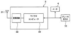
- FIG. 2B is a diagram showing a block configuration of the TPMS-ECU 3.
- FIG. 3 is a timing chart for explaining wheel position detection.
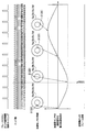
- FIG. 4 is an image diagram showing changes in gear information.
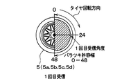
- FIG. 5A is a schematic diagram illustrating the wheel position determination logic.
- FIG. 5B is a schematic diagram illustrating the wheel position determination logic.
- FIG. 5C is a schematic diagram illustrating wheel position determination logic.
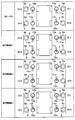
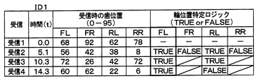
- FIG. 6A is a chart showing the evaluation result of the wheel position of ID1
- FIG. 6B is a chart showing the evaluation result of the wheel position of ID2
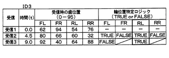
- FIG. 6C is a chart showing the evaluation result of the wheel position of ID3.
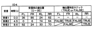
- FIG. 6D is a chart showing the evaluation results of the wheel position of ID4.
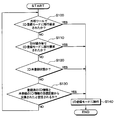
- FIG. 7 is a flowchart of registration start determination processing executed by the TPMS-ECU 3.
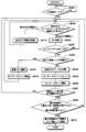
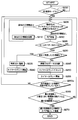
- FIG. 8 is a flowchart of the spare wheel registration process executed by the TPMS-ECU 3.
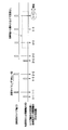
- FIG. 9 is a time chart when frames are received from spare wheels of the host vehicle and other vehicles.
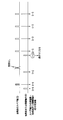
- FIG. 10 is a time chart when frames are received from spare wheels of the host vehicle and other vehicles.
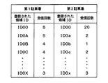
- FIG. 11 is a chart showing the relationship between the candidate ID registered and the number of receptions when the vehicle is parked in the first parking lot and then parked in the second parking lot after shifting to the registration mode.
- FIG. 12 is a flowchart of spare wheel registration processing executed by the TPMS-ECU 3 described in the second embodiment of the present disclosure.
- FIG. 1 is a diagram illustrating an overall configuration of a TPMS to which a wheel position detection device according to a first embodiment of the present disclosure is applied.
- the upper direction in the drawing of FIG. 1 corresponds to the front of the vehicle 1, and the lower direction of the drawing corresponds to the rear of the vehicle 1.
- TPMS in this embodiment is demonstrated.
- the TPMS is provided in the vehicle 1, and includes a transmitter 2, an ECU for TPMS (hereinafter referred to as TPMS-ECU) 3 serving as a receiver, and a meter 4. Yes.
- the wheel position detection device uses the transmitter 2 and TPMS-ECU 3 provided in the TPMS, and the wheels provided corresponding to the wheels 5 (5a to 5e) from the brake control ECU (hereinafter referred to as brake ECU) 10.
- the wheel position is specified by acquiring gear information obtained from detection signals of the speed sensors 11a to 11d.
- the transmitter 2 is attached to each of the wheels 5a to 5e including the traveling wheels 5a to 5d and the spare wheel 5e.
- the transmitter 2 detects the air pressure of the tires attached to the wheels 5a to 5e, and stores information related to the tire air pressure indicating the detection result in the frame together with the unique ID information of each transmitter 2 and transmits it.
- acceleration on data hereinafter referred to as G-ON data
- G-ON data acceleration off data
- G-OFF data is stored.
- G-ON data and G-OFF data correspond to data indicating the state of the acceleration sensor 22.
- the transmitter 2 has a function of detecting that the acceleration sensor 22 is turned on, and stores G-ON data or G-OFF data in a frame based on the detection result. Yes.
- the transmitter 2 is provided with a physical switch (not shown) in which a movable contact that is displaced according to acceleration in the centrifugal direction is in contact with a fixed contact. Is detected to have been turned on.
- the TPMS-ECU 3 is attached to the vehicle body 6 side of the vehicle 1 and receives the frame transmitted from the transmitter 2 and performs various processes and calculations based on the detection signal stored therein. Thus, wheel position detection and tire air pressure detection are performed.
- the transmitter 2 creates a frame by, for example, FSK (frequency shift keying), and the TPMS-ECU 3 demodulates the frame to read data in the frame to detect the wheel position and the tire air pressure.
- 2A and 2B show block configurations of the transmitter 2 and the TPMS-ECU 3.
- the transmitter 2 includes a sensing unit 21, an acceleration sensor 22, a microcomputer 23, a transmission circuit 24, and a transmission antenna 25, and supplies power from a battery (not shown). Each part is driven based on the above.
- the sensing unit 21 includes a diaphragm type pressure sensor 21a and a temperature sensor 21b, for example, and outputs a detection signal corresponding to the tire pressure and a detection signal corresponding to the temperature.
- the acceleration sensor 22 is used to detect the position of the sensor itself on the traveling wheels 5a to 5d to which the transmitter 2 is attached, that is, to detect the position of the transmitter 2 and the vehicle speed.
- the acceleration sensor 22 according to the present embodiment is, for example, the acceleration acting on the traveling wheels 5a to 5d when the traveling wheels 5a to 5d are rotated, in the radial direction of each traveling wheel 5a to 5d, that is, the acceleration in both directions perpendicular to the circumferential direction.
- a corresponding detection signal is output.
- the microcomputer 23 is a well-known one having a control unit (first control unit) and the like, and executes predetermined processing according to a program stored in a memory in the control unit.
- Individual ID information including identification information unique to the transmitter for identifying each transmitter 2 and identification information unique to the vehicle for identifying the host vehicle is stored in the memory in the control unit.
- the microcomputer 23 receives the detection signal related to the tire pressure from the sensing unit 21, processes the signal and processes it as necessary, and stores the information related to the tire pressure in the frame together with the ID information of each transmitter 2. .
- the microcomputer 23 monitors the detection signal of the acceleration sensor 22 to detect the position (angle detection) of the transmitter 2 on the traveling wheels 5a to 5d to which the transmitters 2 are attached, and to detect the vehicle speed. ing.
- the microcomputer 23 creates the frame, the microcomputer 23 transmits the frame (data transmission) from the transmission antenna 25 to the TPMS-ECU 3 via the transmission circuit 24 based on the position detection result of the transmitter 2 and the vehicle speed detection result. )I do.
- the microcomputer 23 starts frame transmission on the condition that the vehicle 1 is traveling, and at a timing at which the angle of the acceleration sensor 22 becomes a predetermined angle based on the detection signal of the acceleration sensor 22. Repeated frame transmission. Whether the vehicle is running is determined based on the vehicle speed detection result, and the angle of the acceleration sensor 22 is determined based on the position detection result of the transmitter 2 based on the detection signal of the acceleration sensor 22. .
- the microcomputer 23 detects the vehicle speed using the detection signal of the acceleration sensor 22, and determines that the vehicle 1 is running when the vehicle speed becomes a predetermined speed (for example, 5 km / h) or more.
- the output of the acceleration sensor 22 includes acceleration based on centrifugal force (centrifugal acceleration).
- the vehicle speed can be calculated by integrating the centrifugal acceleration and multiplying the coefficient. For this reason, the microcomputer 23 calculates the centrifugal acceleration by removing the gravitational acceleration component from the output of the acceleration sensor 22, and calculates the vehicle speed based on the centrifugal acceleration.
- the acceleration sensor 22 outputs a detection signal corresponding to the rotation of each of the traveling wheels 5a to 5d
- the gravitational acceleration component is included in the detection signal during traveling, and the amplitude corresponding to the wheel rotation.
- a signal having For example, the amplitude of the detection signal is a negative maximum amplitude when the transmitter 2 is located at the upper position around the central axis of the traveling wheels 5a to 5d, zero when located at the horizontal position, and a position at the lower position. When it is, the maximum amplitude is positive.
- the position of the acceleration sensor 22 can be detected based on this amplitude, and the acceleration sensor 22 is located at an upper position around the angle of the position of the transmitter 2, for example, the central axis of each traveling wheel 5a to 5d.
- the angle formed by the acceleration sensor 22 when the time is 0 ° can be grasped.
- the frame transmission from each transmitter 2 is performed at the start timing when the acceleration sensor 22 reaches a predetermined angle at the same time when the vehicle speed reaches the predetermined speed or after the vehicle speed reaches the predetermined speed.
- the frame is transmitted repeatedly at the timing when the angle formed by the acceleration sensor 22 becomes the same angle as the first frame transmission.
- the angle formed by the acceleration sensor 22 may be the same as that at the time of the first frame transmission.
- the frame transmission is always performed every time the angle is reached. For example, it is preferable that frame transmission is performed only once in a predetermined time (for example, 15 seconds).
- the transmission circuit 24 functions as an output unit that transmits a frame transmitted from the microcomputer 23 to the TPMS-ECU 3 through the transmission antenna 25.
- frame transmission for example, radio waves in the RF band are used.
- the transmitter 2 configured in this manner is attached to an air injection valve in each of the wheels 5a to 5e, for example, and is arranged so that the sensing unit 21 is exposed inside the tire.
- the transmitter 2 detects the tire air pressure of the wheel to which the transmitter 2 is attached, and when the vehicle speed exceeds the predetermined speed as described above, the angle of the acceleration sensor 22 of each traveling wheel 5a to 5d becomes a predetermined angle.
- frame transmission is repeatedly performed through the transmission antenna 25 provided in each transmitter 2. After that, it is possible to transmit a frame from the transmitter 2 at the timing when the angle of the acceleration sensor 22 of each traveling wheel 5a to 5d becomes a predetermined angle.
- the mode is switched from the wheel position determination mode to the periodic transmission mode, and frame transmission is performed at a longer fixed period (for example, every minute), so that the TPMS-ECU 3 A signal related to tire pressure is periodically transmitted to the side.
- the transmission timing of each transmitter 2 can be shifted, and reception by the TPMS-ECU 3 side due to radio wave interference from a plurality of transmitters 2 is possible. It can be prevented from disappearing.
- the TPMS-ECU 3 is configured to include a receiving antenna 31, a receiving circuit 32, a microcomputer 33, and the like.
- the TPMS-ECU 3 is indicated by the number of teeth (or the number of teeth) of the gears rotated together with the traveling wheels 5a to 5d by acquiring gear information from the brake ECU 10 through an in-vehicle LAN such as CAN as will be described later. The tooth position is acquired.
- the receiving antenna 31 is for receiving a frame sent from each transmitter 2.
- the receiving antenna 31 is fixed to the vehicle body 6 and may be an internal antenna disposed in the main body of the TPMS-ECU 3, or may be an external antenna in which wiring is extended from the main body.
- the receiving circuit 32 functions as an input unit that receives a transmission frame from each transmitter 2 received by the receiving antenna 31 and sends the frame to the microcomputer 33.
- the receiving circuit 32 transmits the received signal to the microcomputer 33.
- the microcomputer 33 corresponds to a second control unit, and executes wheel position detection processing according to a program stored in a memory in the microcomputer 33. Specifically, the microcomputer 33 performs wheel position detection based on the relationship between the information acquired from the brake ECU 10 and the reception timing at which the transmission frame from each transmitter 2 is received. From the brake ECU 10, in addition to the wheel speed information of the traveling wheels 5a to 5d, the gear information of the wheel speed sensors 11a to 11d provided corresponding to the traveling wheels 5a to 5d is acquired at predetermined intervals (for example, 10 ms). is doing.
- Gear information is information indicating the tooth positions of gears (gears) that are rotated together with the traveling wheels 5a to 5d.
- the wheel speed sensors 11a to 11d are constituted by, for example, electromagnetic pickup sensors arranged to face the gear teeth, and change the detection signal as the gear teeth pass. Since these types of wheel speed sensors 11a to 11d output square pulse waves corresponding to the passage of teeth as detection signals, the rising and falling of the square pulse waves pass through the tooth edge of the gear. Will be expressed. Therefore, the brake ECU 10 counts the number of teeth of the gear, that is, the number of passing edges, from the number of rising and falling edges of the detection signals of the wheel speed sensors 11a to 11d, and the tooth edge at that time is counted every predetermined period. The number is transmitted to the microcomputer 33 as gear information indicating the tooth position. Thereby, in the microcomputer 33, it is possible to grasp which tooth of the gear has passed.
- the number of tooth edges is reset every time the gear rotates once. For example, when the number of teeth provided on the gear is 48 teeth, the number of edges is counted as a total of 96 from 0 to 95, and when the count value reaches 95, it is returned to 0 and counted again.
- the number of tooth edges of the gear is transmitted from the brake ECU 10 to the microcomputer 33 as gear information.
- the number of teeth may be a count value of the number of passing teeth.
- the number of edges or teeth passed during the predetermined period is transmitted to the microcomputer 33, and the microcomputer 33 adds the number of edges or teeth passed during the predetermined period to the previous number of edges or teeth. You may make it count the number of edges or the number of teeth in the period. That is, it is only necessary that the microcomputer 33 can finally acquire the number of edges or the number of teeth in the cycle as gear information.
- the brake ECU 10 resets the number of gear teeth (or the number of teeth) every time the power is turned off, but again starts measuring at the same time when the power is turned on or when the vehicle speed reaches the predetermined vehicle speed. ing. Thus, even if the power is turned off every time the power is turned off, the same teeth are represented by the same number of edges (or the number of teeth) while the power is turned on.
- the microcomputer 33 measures the reception timing when the frame transmitted from each transmitter 2 is received, and the frame reception timing is determined from the number of edges (or the number of teeth) of the acquired gear.
- the wheel position is detected based on the number of edges (or the number of teeth) of the gear. As a result, it is possible to perform wheel position detection that identifies which traveling wheel 5a to 5d each transmitter 2 is attached to. A specific method for detecting the wheel position will be described in detail later.
- the microcomputer 33 stores the ID information of each transmitter 2 in association with the position of each traveling wheel 5a to 5d to which each transmitter 2 is attached based on the result of wheel position detection. After that, based on the ID information stored in the transmission frame from each transmitter 2 and the data related to the tire pressure, the tire pressure of each of the traveling wheels 5a to 5d is detected, and an electric signal corresponding to the tire pressure is sent to the CAN. To the meter 4 through the in-vehicle LAN. For example, the microcomputer 33 detects a decrease in tire air pressure by comparing the tire air pressure with a predetermined threshold Th, and outputs a signal to that effect to the meter 4 when a decrease in tire air pressure is detected. Thus, the meter 4 is informed that the tire air pressure of any of the four traveling wheels 5a to 5d has decreased.
- the meter 4 functions as an alarm unit, and as shown in FIG. 1, is arranged at a place where the driver can visually recognize, and is configured by a meter display or the like installed in an instrument panel in the vehicle 1, for example. .
- a signal indicating that the tire air pressure has decreased is sent from the microcomputer 33 in the TPMS-ECU 3, the meter 4 displays the decrease in tire air pressure while identifying the traveling wheels 5 a to 5 d. Informs the driver of a decrease in tire pressure of a specific wheel.
- the microcomputer 23 monitors the detection signal of the acceleration sensor 22 at every predetermined sampling period based on the power supply from the battery, thereby determining the vehicle speed and the angle of the acceleration sensor 22 at each of the wheels 5a to 5e. Detected. Then, when the vehicle speed reaches a predetermined speed, the microcomputer 23 repeatedly transmits frames at a timing at which the angle of the acceleration sensor 22 becomes a predetermined angle. For example, frame transmission from each transmitter 2 is performed with a predetermined angle when the vehicle speed reaches a predetermined speed or a start timing when the acceleration sensor 22 reaches a predetermined angle after the vehicle speed reaches the predetermined speed. I have to. The frame is transmitted repeatedly at the timing when the angle formed by the acceleration sensor 22 becomes the same angle as the first frame transmission.
- the gear information of the wheel speed sensors 11a to 11d provided corresponding to the traveling wheels 5a to 5d is acquired from the brake ECU 10 every predetermined period (for example, 10 ms). Then, the TPMS-ECU 3 measures the reception timing when the frame transmitted from each transmitter 2 is received, and when the frame reception timing is selected from the number of gear edges (or the number of teeth). Get the number of gear edges (or the number of teeth).
- the reception timing of the frame transmitted from each transmitter 2 does not always coincide with the cycle of acquiring gear information from the brake ECU 10.
- the number of edges (or the number of teeth) of the gear indicated by the gear information acquired in the cycle closest to the reception timing of the frame among the cycles in which the gear information is acquired from the brake ECU 10, that is, the cycle immediately before or immediately after that Can be used as the number of gear edges (or the number of teeth).
- the frame reception timing is obtained by using the number of gear edges (or the number of teeth) indicated by the gear information acquired in the period immediately before and after the frame reception timing from the period in which the gear information is acquired from the brake ECU 10.
- the number of edges (or the number of teeth) of the gear may be calculated.
- the intermediate value of the number of gear edges (or the number of teeth) indicated by the gear information acquired immediately before and after the frame reception timing is used as the number of gear edges (or the number of teeth) at the frame reception timing. Can be used.
- the operation of obtaining the number of gear edges (or the number of teeth) at the reception timing of the frame is repeated every time the frame is received, and the number of gear edges (or the number of gear edges at the received frame reception timing)
- the wheel position is detected based on the number of teeth. Specifically, the variation in the number of gear edges (or the number of teeth) at the frame reception timing is within a predetermined range set based on the number of gear edges (or the number of teeth) at the previous reception timing.
- the wheel position is detected by determining whether or not there is.
- the tooth position indicated by the number of gear edges (or the number of teeth) at the frame reception timing Is almost the same as the previous time. For this reason, the variation in the number of edges (or the number of teeth) of the gears at the frame reception timing is small and falls within a predetermined range. This is true even when multiple frames are received, and the variation in the number of gear edges (or the number of teeth) at the reception timing of each frame is within a predetermined range determined at the first frame reception timing. It will fit.
- the tooth position indicated by the number of edges (or the number of teeth) of the gear at the reception timing of the frame transmitted from the transmitter 2 of the other wheel varies.
- the rotation of the gears of the wheel speed sensors 11a to 11d is linked to the traveling wheels 5a to 5d, the number of gear edges (or the number of teeth) at the reception timing of the frame for the wheel that has received the frame.
- the tooth positions indicated by are almost the same.
- the rotational state of the traveling wheels 5a to 5d varies depending on road conditions, turning or lane change, and therefore the traveling state of the traveling wheels 5a to 5d cannot be completely the same. For this reason, for a wheel that is different from the wheel that received the frame, the tooth position indicated by the number of gear edges (or the number of teeth) at the frame reception timing varies.
- the tooth position indicated by the number of gear edges (or the number of teeth) at the frame reception timing varies.
- the wheel position is detected by determining whether or not the variation is within a predetermined range.
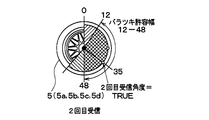
- the variation allowable width which is the allowable width for the number of gear edges (or the number of teeth), is a value corresponding to a range of 180 ° centered on the first reception angle (the range of the first reception angle ⁇ 90 °).
- the number of edges is a range of ⁇ 24 edges centered on the number of edges at the first reception
- the number of teeth is a range of ⁇ 12 teeth centered on the number of teeth at the first reception. In this case, as shown in FIG.
- the wheel having the number of edges (or the number of teeth) may coincide with the wheel on which the frame transmission is performed, and becomes TRUE (correct).
- the variation allowable width is determined around the second reception angle that is the angle of the transmitter 2 at the time of the second frame reception, and is equivalent to 180 ° ( ⁇ 90 °) around the second reception angle. Value. For this reason, a variation allowable width of 180 ° ( ⁇ 90 °) centered on the first reception angle that is the previous allowable variation width and a variation allowable width of 180 ° ( ⁇ 90 °) centered on the second reception angle
- the overlapping portion becomes a new variation allowable width (edge number range is 12 to 48), and the new variation allowable width can be narrowed to the overlapping range.
- the number of gear edges (or the number of teeth) is obtained at each reception timing of the frame, and the corresponding wheel is obtained. This is stored for each (left front wheel FL, right front wheel FR, left rear wheel RL, right rear wheel RR).
- a transmitter that transmits the frame out of the range is transmitted. 2 is excluded from the attached wheel candidates. And the wheel which was not excluded until the last is registered as a wheel with which the transmitter 2 with which the flame
- the right front wheel FR, the right rear wheel RR, and the left rear wheel RL are excluded from the candidates in this order, and the remaining left front wheel FL is finally attached to the transmitter 2 to which the frame is transmitted.
- the wheel is registered in association with the ID information.
- the microcomputer 33 stores the ID information of each transmitter 2 that has transmitted the frame in association with the position of the wheel to which it is attached.
- the TPMS-ECU 3 receives the frame transmitted when the vehicle speed reaches the predetermined speed, and stores the gear information at the reception timing. However, the TPMS-ECU 3 stores a predetermined traveling stop determination speed (for example, 5 km). / H) When it becomes below, the gear information so far is discarded. When the vehicle starts running again, the wheel position is newly detected as described above.
- the basic wheel position detection is performed by the above method. This makes it possible to detect the wheel positions of the left front wheel FL, the right front wheel FR, the left rear wheel RL, and the right rear wheel RR, which are the traveling wheels 5a to 5d.
- ID information that is a candidate for registration of ID information stored in the frame (hereinafter referred to as candidate ID) can be.
- candidate ID ID information that is a candidate for registration of ID information stored in the frame.
- the timing at which the frame transmitted from the transmitter of the other vehicle is received does not match the tooth position of the gear of any wheel of the own vehicle. For this reason, it can avoid registering the ID information of the transmitter of another vehicle, and can register only the ID information of the transmitter 2 of the own vehicle.
- the ID information of the transmitter of the other vehicle can also be a candidate ID.
- the ID information of the transmitter can also be a candidate ID.
- the ID information is only included when the tooth position at the frame reception timing is included in the variation allowable range continuously for a predetermined number of times (for example, 10 times). Is registered.
- the number of gear edges (or teeth) acquired at each frame reception timing is also received for that frame, as in the case of the host vehicle. It is determined whether or not (number) is within the range of variation tolerance. And, similarly to the transmitter 2 of the own vehicle, for the frame transmitted from the transmitter of the other vehicle, the wheel that is out of the range of the allowable variation range is selected from the wheel candidates attached to the transmitter 2 to which the frame is transmitted. Will be excluded. At this time, since the elimination method is used, at the time when only one wheel is finally left without being excluded in each frame, the wheel candidate to which the transmitter 2 to which the wheel transmits the frame is attached. It becomes.
- the ID information of the transmitter attached to the wheels of the other vehicle is erroneously registered as that of the own vehicle.
- the frames transmitted from the transmitters attached to the wheels of the other vehicle are not of the own vehicle, and thus are likely to vary, and are transmitted from the transmitter 2 attached to the traveling wheels 5a to 5d of the own vehicle. It tends to be excluded from wheel candidates earlier than the frame. For this reason, most of the frames transmitted from the transmitters of the wheels of other vehicles are identified as wheel candidates that are attached to the transmitters that transmitted the frames. It is easy to become the state that was done.
- the ID information registration condition is that the tooth position at the reception timing of the frame is continuously included within the tolerance range after the wheel is specified, the other vehicle is in the meantime.
- the tooth position of the reception timing of the frame from the transmitter is out of the tolerance range. Therefore, it is possible to prevent the ID information of the transmitter attached to the wheels of the other vehicle from being erroneously registered as that of the own vehicle.
- the wheel positions of the left front wheel FL, the right front wheel FR, the left rear wheel RL, and the right rear wheel RR that are the traveling wheels 5a to 5d can be detected by the above-described method.
- the process for specifying the spare wheel 5e is further performed.
- the TPMS-ECU 3 determines whether or not there is data indicating the state of the acceleration sensor 22 stored in the received frame and the traveling history of the host vehicle, and based on the determination result and the like.
- the ID information of the transmitter 2 of the spare wheel 5e in the vehicle is also registered.
- the spare wheel registration process executed by TPMS-ECU 3 will be described. This process is performed together with the wheel position detection process of the traveling wheels 5a to 5d described above. For example, when a power switch is turned on to turn on the TPMS-ECU 3 when the wheel position detection execution switch (not shown) is operated, the TPMS-ECU 3 enters the ID registration mode. Then, this processing is executed every predetermined control period together with the wheel position detection processing of the traveling wheels 5a to 5d.
- the registration start determination process shown in FIG. 7 is executed to determine whether or not it is necessary to shift to the ID registration mode.
- the spare wheel registration process shown in FIG. 8 is performed. By executing, the wheel position detection is performed while leaving only the candidate ID that should be truly left. Note that the processing shown in FIGS. 7 and 8 is executed at predetermined control cycles when, for example, the TPMS-ECU 3 is turned on by turning on the IG.
- steps 100 to 130 it is determined whether or not the situation where the transition to the ID registration mode is required has been made.
- step 100 it is determined whether or not a request for shifting to the ID registration mode has been issued through an external tool (not shown) that instructs execution of wheel position detection.
- the external tool for example, transmits a command for requesting transition to the ID registration mode to the TPMS-ECU 3, and transmits the command to the TPMS-ECU 3 through the in-vehicle LAN such as CAN even if the command is transmitted to the TPMS-ECU 3 using radio waves. It may be a thing.
- step 110 it is determined whether or not a request for shifting to the ID registration mode has been issued by operating a wheel position detection execution switch (not shown).
- a wheel position detection execution switch is provided on, for example, an instrument panel. When the execution switch is operated by a user, it is transmitted to the TPMS-ECU 3 through an in-vehicle LAN such as CAN.
- step 120 it is determined whether or not the ID information of the transmitter 2 of each wheel 5a to 5d is in an unregistered state. For example, immediately after the vehicle manufacture is completed, the ID information of any transmitter 2 is still unregistered, and it is necessary to detect the wheel position.
- step 130 it is determined whether or not it is assumed that the tire has been changed based on the comparison of the number of times of reception of the registered ID information and the unregistered ID information. Even in such a case, it is necessary to detect the wheel position. For example, it is determined that the tire replacement or the like is assumed when the number of times of reception of the unregistered ID information is more than a predetermined number of times than the registered ID information.
- step 140 the process proceeds to the ID registration mode, and the process is terminated. Return and repeat the above process. In this way, the registration start determination process for determining whether to start the registration of the ID information of the transmitter 2 of the host vehicle by detecting the wheel position is completed.
- step 200 it is first determined in step 200 whether or not the ID registration mode is set. If the transition to the ID registration mode has been performed in step 140 of FIG. 7 described above, an affirmative determination is made in this step and the routine proceeds to step 205.
- Step 205 it is determined whether or not there is a candidate ID whose timer count value is equal to or longer than a predetermined time (for example, 10 minutes).
- the count value of the timer here is a count value after the timer count is started in Steps 240 and 255 described later, and is counted for each candidate ID, and a frame including each candidate ID is received last time. It represents the elapsed time from.
- the transmission interval of frames from the transmitter 2 is basically determined although it varies depending on the situation. For example, during a period in which wheel position detection may be performed, such as when the vehicle starts to travel, the wheel position determination mode is set and the frame transmission interval is relatively short. Further, when the time assumed to be necessary for wheel position detection elapses, the mode is switched to the regular transmission mode, and frame transmission is performed at a longer fixed period. Further, when the vehicle is stopped, there may be a case where a transmission mode during stopping that sets a transmission cycle longer than that of the regular transmission mode is provided and frame transmission is performed every longer fixed cycle. However, in any of these modes, frame transmission is performed within a certain period, and frame reception is performed on the TPMS-ECU 3 side.
- the system has a specification that a frame transmitted from the transmitter 2 of the own vehicle is received at least once within a predetermined time, and in some countries, this is obligated by laws and regulations. For example, it is specified that a frame transmitted from the transmitter 2 of the own vehicle is received during a predetermined period of 20 minutes in North America and 10 minutes in Europe.
- the frame transmitted from each transmitter 2 of the host vehicle is received by the TPMS-ECU 3, and for candidate IDs not received during the predetermined period, transmission of the host vehicle is performed. It can be determined that the ID information is not the machine 2.
- step 205 when it is determined in step 205 that there is a corresponding ID as described above, the process proceeds to step 210 to delete the corresponding ID from the candidate IDs, and then the process returns to step 205.
- step 205 determines whether there is no corresponding ID. If it is determined in step 205 that there is no corresponding ID, the process proceeds to step 220. Then, when a frame transmitted as RF reception, that is, a radio wave in the RF band, is received, the processing after step 225 is executed.
- step 225 it is determined whether G-OFF data is stored as data indicating the state of the acceleration sensor 22 in the received frame. That is, it is determined whether or not the acceleration sensor 22 provided in the transmitter 2 that has transmitted the received frame is in an on state.
- the traveling wheels 5a to 5d when the host vehicle is traveling, if the wheel speed of the traveling wheels 5a to 5d reaches a predetermined speed, the frame of the transmitter 2 attached to the traveling wheels 5a to 5d is displayed. Stores G-ON data. However, in the case of the spare wheel 5e, even if the vehicle is running, it cannot be rotated, and therefore G-OFF data is stored in the frame of the transmitter 2 attached to the spare wheel 5e. Therefore, when the G-OFF data is stored in the received frame, the received frame may be transmitted from the transmitter 2 of the spare wheel 5e. Therefore, if an affirmative determination is made in this step, the process proceeds to step 230 and thereafter, and if a negative determination is made, the process returns to step 205.
- step 230 it is determined whether or not the ID information stored in the currently received frame is the ID received for the first time. If the determination is affirmative, the process proceeds to step 235 and is registered as a candidate ID. Then, the process proceeds to step 240, and the timer count for the candidate ID is started.
- step 230 if a negative determination is made in step 230, since the ID information stored in the frame received this time has already been registered as a candidate ID, the process proceeds to step 245 to receive a registered candidate ID. Add a number.
- step 250 the timer count for the candidate ID is once reset, and then the process proceeds to step 255 to start the timer count for the candidate ID. Thereby, the timer count for the candidate ID is performed again from the beginning.
- step 260 it is determined whether or not there is a travel history after shifting to the registration mode.
- the predetermined period here is set to a frame transmission cycle of the transmitter 2 of the spare wheel 5e, that is, a time longer than the transmission cycle longer than in the regular transmission mode, and the frame transmitted from the transmitter 2 of the spare wheel 5e. Is set to a time at which the receiver 3 receives at least once.
- Whether or not the vehicle state is running is determined by obtaining vehicle speed data from the brake ECU 10 because the brake ECU 10 performs vehicle speed calculation based on detection signals from the wheel speed sensors 11a to 11d. be able to.
- the candidate ID When there is a travel history after shifting to the registration mode, the candidate ID is basically registered in a situation where there is no specific vehicle around. For this reason, it is considered that the frame is received from the transmitter 2 of the spare wheel 5e, and the ID information of the transmitter 2 of the spare wheel 5e in the host vehicle is already registered in the candidate ID.
- a candidate ID is registered in a situation where a specific vehicle exists around.
- a candidate ID may be registered in a situation where a plurality of vehicles are parked around such as a parking lot or waiting for a signal.
- the ID information of the transmitter of the wheel of the other vehicle may be registered in the candidate ID and reach the memory capacity. There is sex. In such a case, there is a possibility that the ID information of the transmitter 2 of the spare wheel 5e in the own vehicle cannot be registered in the candidate ID.
- step 260 it is determined whether or not there is a travel history after shifting to the registration mode. If the determination is affirmative, the ID information of the transmitter 2 of the spare wheel 5e in the host vehicle is already registered in the candidate ID. If not, the process proceeds to step 265. If a negative determination is made in step 260, the ID information of the transmitter 2 of the spare wheel 5e in the own vehicle may not be registered in the candidate ID, and the process returns to step 205.
- step 260 If a negative determination is made in step 260 as described above, the frame including the ID information once registered as the candidate ID will not be received when the vehicle travels thereafter. It is determined that there is ID information. As a result, the ID information of the transmitters of other vehicles can be excluded and the memory capacity can be made free. Thereby, even if the ID information of the transmitter 2 of the spare wheel 5e in the host vehicle is not registered in the candidate ID, it is registered as a candidate ID due to the vacant memory capacity.
- step 265 it is determined whether the received frame is the transmitter 2 of the spare wheel 5e in the own vehicle or the transmitter of another vehicle. If the frame is transmitted from the transmitter 2 of the spare wheel 5e in the host vehicle, the ID information of the frame is registered as that of the spare wheel 5e.
- step 265 it is determined whether or not the difference between the maximum number of receptions and the second largest number of receptions is 3 or more and the maximum number of receptions is 4 or more. Thereby, it is determined whether the received frame is the transmitter 2 of the spare wheel 5e in the own vehicle or the transmitter of the other vehicle. This will be described with reference to time chart examples shown in FIGS.
- the frame When the vehicle state of the host vehicle is running and the G-OFF data is stored in the received frame, the frame is basically attached to the spare wheel 5e in the host vehicle.
- a transmitter 2 is assumed. However, there may be a case where the frame is not transmitted by the transmitter 2 of the spare wheel 5e in the own vehicle. For example, when there is another vehicle running side by side with the host vehicle, there is a possibility that the frame is transmitted from a spare wheel transmitter of the other vehicle. Further, when another vehicle or wheel is loaded on the host vehicle, there is a possibility that the frame is transmitted from a wheel of another vehicle being loaded or a transmitter of the loaded wheel.
- the loaded other vehicle or loaded wheel is separated from the own vehicle, so that the frame transmitted from the loaded vehicle wheel or loaded wheel transmitter cannot be received. For this reason, there is a difference in the number of received frames, and a frame with a large number of received frames is transmitted from the transmitter 2 of the spare wheel 5e in the host vehicle. It can be determined that it is transmitted from the transmitter of the loading wheel.
- a frame transmitted from the transmitter 2 of the spare wheel 5e in the host vehicle and a frame transmitted from the transmitter of the other vehicle or the loaded wheel are transmitted at predetermined frame transmission timings (for example, at intervals of 96 s). ).
- the transmitter 2 normally performs acceleration detection or the like at a low frequency (for example, at intervals of 16 s) in order to suppress current consumption.
- the acceleration sensor 22 is not in an on state, the frequency is even lower than normal (for example, at an interval of 96 s). Acceleration detection and so on are performed.
- the frame transmitted from the transmitter 2 of the spare wheel 5e has not been received yet when the frame transmitted from the transmitter of the other vehicle or the loaded wheel is received immediately.
- the difference between the maximum received number and the second most received number is that the number of received frames transmitted from the transmitter 2 of the spare wheel 5e is 0 and the frame transmitted from the transmitter of the other vehicle or the loaded wheel Since the number of reception is 1, it is 1.
- the difference between the maximum received number and the second most received number is the reception of the frame transmitted from the transmitter 2 of the spare wheel 5e.
- the number is 1, and the number of received frames transmitted from the transmitter of the other vehicle or the loaded wheel is 1, so it is 0.
- the difference between the maximum reception number and the second most reception number is finally 3 or more, and it can be determined that the ID information of the frame with the maximum reception number is the ID information of the transmitter 2 of the spare wheel 5e.
- the difference between the maximum reception number and the second most reception number is 2 or more, it is determined that the ID information of the frame with the maximum reception number is the ID information of the transmitter 2 of the spare wheel 5e.
- the frame transmitted from the transmitter 2 of the spare wheel 5e may not be received by the TPMS-ECU 3 due to data collision during transmission or interference of disturbing radio waves.
- the difference between the maximum received number and the second most received number is 2. End up.
- the difference between the maximum received number and the second most received number is 3 or more, it is determined that the ID information of the frame with the maximum received number is the ID information of the transmitter 2 of the spare wheel 5e. .
- the ID information of the transmitter of the loaded other vehicle or the loaded wheel is mistakenly registered as the ID information of the transmitter 2 of the spare wheel 5e in the own vehicle due to the data missing once.
- the shorter the transmission timing the more likely data collision occurs, and there is a possibility that the frame transmitted by the transmitter of the spare wheel 5e cannot be received by the TPMS-ECU3. It is effective to set the difference from the large number of receptions to 3 or more.
- step 265 it is also determined that the maximum number of receptions is 4 or more.
- the maximum number of receptions is set to 4 or more.
- the higher the lower limit value the better the reliability.
- the lower limit value of the maximum number of receptions is set to 4 times here.
- this determination item for the maximum number of receptions is not an indispensable item in the determination in step 265, and only the difference between the maximum reception number and the second most reception number may be used as the determination item.
- step 265 it is determined that there is a difference between the maximum received number and the second most received number. Then, when an affirmative determination is made in step 265, the process proceeds to step 270, and the ID information of the frame with the maximum number of receptions is registered as the ID information of the transmitter 2 of the spare wheel 5e in the host vehicle, thereby transmitting the spare wheel 5e. Registration of the ID information of the machine 2 is completed.
- the tire air pressure is detected. Specifically, at the time of tire pressure detection, a frame is transmitted from each transmitter 2 at regular intervals, and every time a frame is transmitted from each transmitter 2, four traveling wheels and spare wheels are transmitted. The frame is received by the TPMS-ECU 3. Then, the TPMS-ECU 3 identifies which frame is sent from the transmitter 2 attached to the wheels 5a to 5e based on the ID information stored in each frame, and determines each frame from information related to the tire pressure. The tire pressure of the wheels 5a to 5e is detected.
- the spare wheel 5e is excluded from the notification target when the tire pressure decreases because the tire pressure does not hinder even if the tire pressure is decreased, and the tire pressure of the traveling wheels 5a to 5d is matched. Only a decrease in tire air pressure may be reported.
- the tooth positions of the gears 12a to 12d are shown based on the detection signals of the wheel speed sensors 11a to 11d that detect the passage of the teeth of the gears 12a to 12d rotated in conjunction with the wheels 5a to 5d. Gear information is acquired every predetermined period. And if the variation allowable width is set based on the tooth position at the reception timing of the frame and the tooth position at the reception timing of the frame after setting the variation allowable width is outside the range of the variation allowable width, The wheel is excluded from the wheel candidates attached to the transmitter 2 to which the frame is transmitted, and the remaining wheels are registered as wheels to which the transmitter 2 to which the frame is transmitted is attached. For this reason, the wheel positions of the traveling wheels 5a to 5d can be specified even if a large amount of data is not available.
- spare wheel registration processing it is determined whether or not G-OFF data is stored when the vehicle state is traveling, and only ID information of a frame in which G-OFF data is stored during traveling is used as a spare wheel. Register as a candidate ID of 5e. And ID information of spare wheel 5e is specified from this registration ID. Specifically, after the transition to the registration mode, it is confirmed that there is a traveling history, and only when there is a traveling history, the frame of the own vehicle and that of the other vehicle are selected from the frames storing the G-OFF data. It is made to discriminate. For example, it is determined whether the difference between the maximum number of received frames in which G-OFF data is stored and the second most received number is a predetermined number (eg, 3) or more.
- a predetermined number eg, 3
- the ID information of the transmitter 2 of the spare wheel 5e in the own vehicle is not registered in the candidate ID due to the memory capacity being full or the like, the ID information of the spare wheel 5e is determined. I can not. Accordingly, it is possible to prevent the ID information of the transmitter of the surrounding vehicle, the loaded other vehicle, or the loaded wheel from being erroneously registered as the ID information of the transmitter 2 of the spare wheel 5e in the own vehicle.
- the ID information of the transmitter 2 of the traveling wheels 5a to 5d and the spare wheel 5e can be registered in this way, it is not necessary to provide an antenna for each wheel, and the number of parts increases due to the need for additional parts. As a result, high costs can be avoided.
- step 260 the spare wheel registration process is executed in the present embodiment as in the first embodiment. However, instead of step 260, the processing of step 260a is performed.
- step 260a it is determined whether or not the identification information of the traveling wheels 5a to 5d has been specified.
- the identification of the ID information of the traveling wheels 5a to 5d is not completed if there is no traveling history after shifting to the registration mode. For this reason, the completion of the identification of the ID information of the traveling wheels 5a to 5d is one of results obtained when there is a traveling history after shifting to the registration mode. Therefore, if an affirmative determination is made in step 260a, the processing proceeds to step 265 and the subsequent steps and the same processing as in the first embodiment is performed.
- the criteria for determining whether or not there is a travel history in step 260 of FIG. 8 described in the first embodiment may be changed as appropriate.
- the travel history after the transition to the registration mode based on the event that occurs as a result of the travel history after the transition to the registration mode. It can be determined whether or not there is.
- another determination criterion can be used, such as the fact that there is a travel history when the travel distance after shifting to the registration mode reaches a predetermined distance.
- the variation allowable width is changed at each frame reception timing, and the variation allowable width is gradually reduced. did.
- other methods may be used for the wheel position detection method on the traveling wheels 5a to 5d side.
- the variation allowable width is changed at each frame reception timing so that the variation allowable width is gradually narrowed.
- the variation allowable width set around the tooth position is constant. .
- the variation allowable width set around this tooth position can also be changed.
- the variation in the tooth position may increase as the vehicle speed increases. For this reason, it is possible to set a more accurate variation allowable width by increasing the variation allowable width as the vehicle speed increases.
- the longer the sampling period when the acceleration sensor 22 performs acceleration detection the lower the timing detection accuracy when the angle of the acceleration sensor 22 becomes a predetermined angle, and therefore the variation tolerance is changed accordingly.
- a more accurate variation tolerance can be set. In that case, since the transmitter 2 knows the sampling period and the like, the frame transmitted by the transmitter 2 can be transmitted including data for determining the variation allowable width.
- the angle at which frame transmission is performed is that the position where the angle is 0 ° is when the acceleration sensor 22 is positioned above the center axis of each wheel 5a to 5d.
- this is merely an example, and an arbitrary position in the circumferential direction of the wheel may be set to 0 °.
- the TPMS-ECU 3 acquires the gear information from the brake ECU 10. However, since it is sufficient that the TPMS-ECU 3 can acquire the number of teeth or the number of teeth of the gear as the gear information, it may be acquired from another ECU, or the detection signals of the wheel speed sensors 11a to 11d are input, The number of teeth or the number of teeth of the gear may be acquired from the detection signal.
- the case where the TPMS-ECU 3 and the brake ECU 10 are configured as separate ECUs has been described, but there may be a case where they are configured as a single ECU in which these are integrated.
- the ECU directly inputs the detection signals of the wheel speed sensors 11a to 11d, and acquires the number of teeth or the number of teeth of the gear from the detection signals.
- the number of teeth or the number of teeth of the gear can always be obtained, unlike the case where these pieces of information are obtained every predetermined period, based on the gear information exactly at the reception timing of the frame. Wheel position detection can be performed.
- the wheel position detection device provided for the vehicle 1 provided with the traveling wheels 5a to 5d and the spare wheel 5e has been described.
- the vehicle has a larger number of traveling wheels and spare wheels.
- the present disclosure can be applied.
- the wheel speed sensors 11a to 11d can detect the passage of gear teeth that are rotated in conjunction with the rotation of the wheels 5a to 5d. For this reason, as a gear, what is necessary is just the structure from which the magnetic resistance differs in which the part located in between the tooth
- the outer edge portion is made uneven so that the outer peripheral surface is not only a general structure composed of a convex portion that becomes a conductor and a space that becomes a nonconductor, but, for example, the outer peripheral surface becomes a conductor and a nonconductor
- a rotor switch made of an insulator is also included (see, for example, Japanese Patent Laid-Open No. 10-048233).
- the steps shown in each figure correspond to a device that executes various processes. That is, the part that executes the process of step 225 performs the first determination apparatus, the part that executes the process of step 260 performs the second determination apparatus, the part that executes the process of step 230 performs the third determination apparatus, and the process of step 265
- the part to perform corresponds to the fourth determination device.
- the part that executes the process of step 235 corresponds to the candidate registration apparatus
- the part that executes the process of step 245 corresponds to the received number adding apparatus
- the part that executes the process of step 270 corresponds to the registration apparatus.
- each section is expressed as S100, for example.
- each section can be divided into a plurality of subsections, while a plurality of sections can be combined into one section.
- each section configured in this manner can be referred to as a device, module, or means.
Landscapes
- Engineering & Computer Science (AREA)
- Mechanical Engineering (AREA)
- Physics & Mathematics (AREA)
- General Physics & Mathematics (AREA)
- Measuring Fluid Pressure (AREA)
- Arrangements For Transmission Of Measured Signals (AREA)
Abstract
車輪位置検出装置は、車両(1)の各車輪に設けられ、識別情報を含めたフレームを送信する第1制御部(23)と車輪の加速度センサ(22)を有する送信機(2)と、車体に設けられ、前記車輪と前記識別情報とを対応づけて登録する第2制御部(33)を有する受信機(3)とを備える。前記第1制御部は、車輪速度が所定速度に至ったことを検知して、前記加速度センサのデータを前記フレームに格納する。前記第2制御部は、該加速度センサがオンではない条件を判定する第1判定装置(S225)と、前記条件を満たしていると、スペア輪の識別情報の候補に登録する候補登録装置(S235)と、前記車両の走行履歴を判定する第2判定装置(S260)と、走行履歴が有ると、前記スペア輪の識別情報を特定し、前記スペア輪と対応付けて登録する登録装置(S270)とを備える。
Description
本出願は、2015年6月4日に出願された日本特許出願番号2015-114240号に基づくもので、ここにその記載内容を援用する。
本開示は、対象車輪が車両のどの位置に搭載されている車輪かを自動的に検出する車輪位置検出装置、およびそれを備えたダイレクト式のタイヤ空気圧検出システムに関するものである。
従来より、タイヤ空気圧検出システム(以下、TPMS:Tire Pressure Monitoring Systemという)の1つとして、ダイレクト式のものがある。このタイプのTPMSでは、タイヤが取り付けられた車輪側に、圧力センサ等のセンサが備えられた送信機が直接取り付けられている。また、車体側には、アンテナおよび受信機が備えられており、センサからの検出信号が送信機から送信されると、アンテナを介して受信機にその検出信号が受信され、タイヤ空気圧の検出が行われる。
このようなダイレクト式のTPMSでは、送信されてきたデータが自車両のものであるかどうか及び送信機がどの車輪に取り付けられたものかを判別できるようにする必要がある。このため、送信機が送信するデータ中に、自車両か他車両かを判別するため及び送信機が取り付けられた車輪を判別するためのID情報を個々に付与している。
送信データに含まれるID情報から送信機の位置を特定するためには、各送信機のID情報を各車輪の位置と関連づけて受信機側に予め登録しておく必要がある。このため、タイヤのローテーション時や冬用タイヤ交換などの際には、送信機のID情報と車輪の位置関係を受信機に登録し直す必要があり、ユーザが自由にタイヤ交換を行うことができないことから、ID情報の登録作業を自動でできるシステムが求められている。そこで、例えば特許文献1において、ID情報の登録作業を自動的に行えるようにする技術が提案されている。
具体的には、特許文献1に示す装置では、車輪側の送信機に備えた加速度センサの加速度検知信号に基づいて車輪が所定の回転位置(回転角度)になったことを検出し、車輪側からフレーム送信を行わせている。そして、ユーザの登録指示操作が行われると、車輪と連動して回転させられる歯車の歯の通過を車輪速度センサで検出し、フレームの受信タイミングでの歯位置のバラツキ幅に基づいて、車輪位置を特定している。
その他、受信した複数の未知のID情報のうち、一定期間中における受信頻度に着目し、頻度の高いID情報を自車両のID情報として登録する方法もある。また、受信した複数の未知のID情報を含む送信フレームに含まれるタイヤ内の温度や圧力情報に基づき、自車両の走行パターンとタイヤ内の温度や圧力との相関を求めて、自車両の走行パターンに対応するID情報を自車両のID情報として登録する方法もある。さらに、各車輪の近傍にアンテナを配置し、アンテナがフレーム受信をしたときの受信電波の強度(RSSI)を測定し、その値の大きいものをアンテナの近傍の車輪のID情報として登録する方法もある。
しかしながら、従来のID情報の登録方法では、いずれも自車両における走行車輪とスペア輪(補助輪)の双方に取り付けられた受信機のID情報について車輪位置を特定しつつ登録することができない。例えば、特許文献1の方法では、スペア輪については走行に伴って回転させられないため、走行に伴う加速度が発生せず、スペア輪のID情報が自車両のID情報から除外される。また、受信頻度に着目する方法では、走行車輪とスペア輪いずれの場合も同様の受信頻度となることから、自車両のID情報として登録することはできても、車輪位置を特定して各ID情報を登録できない。また、走行パターンを利用する方法では、スペア輪については走行に伴うタイヤ内の温度や圧力の変動が無いことから、スペア輪のID情報が自車両のID情報から除外される。
また、アンテナを各車輪の近傍に配置する手法の場合、スペア輪の近傍にもアンテナを配置すれば、スペア輪を含めた各車輪のID情報を登録することが可能となるが、車輪毎にアンテナという追加部品が必要になり、部品点数の増加ひいてはコスト高を招く。
本開示は、車輪毎にアンテナを備えなくても、スペア輪に取り付けられた送信機のID情報を的確に登録することが可能な車輪位置検出装置およびそれを備えたタイヤ空気圧検出システムを提供することを目的とする。
本開示の第一の態様において、車輪位置検出装置は、車体に対してタイヤを備えた走行車輪およびスペア輪を含む複数の車輪が取り付けられた車両に適用され、前記複数の車輪それぞれに設けられ、固有の識別情報を含めたフレームを作成すると共に送信する第1制御部を有する送信機と、前記車体側に設けられ、所定の登録モードに移行したときに、受信アンテナを介して前記送信機から送信されたフレームを受信することで、該フレームに含まれた前記識別情報毎に、前記フレームを送信してきた前記送信機が前記複数の車輪のいずれに取り付けられたものであるかを特定し、前記複数の車輪と該複数の車輪それぞれに設けられた前記送信機の識別情報とを対応づけて登録する車輪位置検出を行う第2制御部を有する受信機とを備える。前記送信機は、該送信機が取り付けられた車輪の回転に伴って変化する加速度に応じた検出信号を出力する加速度センサを有すると共に、前記第1制御部の機能として、該送信機の取り付けられた車輪の車輪速度が前記加速度センサによる加速度検出が行えるオンの状態となる所定速度に至ったことを検知して、該検知結果に基づいて前記加速度センサの状態を示すデータを前記フレームに格納する機能を有する。前記受信機の前記第2制御部には、受信した前記フレームに格納された前記加速度センサの状態を示すデータが、該加速度センサがオンの状態ではないという条件を満たすか否かを判定する第1判定装置と、前記第1判定装置で前記条件を満たしていると判定されると、前記スペア輪の識別情報の候補に登録する候補登録装置と、前記登録モードに移行してから前記車両の走行履歴が有るか否かを判定する第2判定装置と、前記第2判定装置にて走行履歴が有ると判定されると、前記スペア輪の識別情報の候補に登録された中から、前記スペア輪の識別情報を特定し、当該識別情報が前記スペア輪のものであることを対応付けて登録する登録装置とが備えられている。
上記の車輪位置検出装置のように、車両状態が走行中の際に加速度センサがオンの状態ではないことを示すデータが格納されているか否かを判定し、走行中にそのデータが格納されたフレームのID情報のみをスペア輪の識別情報の候補として登録する。そして、この候補として登録した識別情報の中から、スペア輪の識別情報を特定している。具体的には、登録モードに移行した後に走行履歴が有ることを確認し、走行履歴が有る場合にのみ、加速度センサがオンの状態ではないことを示すデータが格納されたフレームの中から自車両のものと他車両のものとの判別を行うようにしている。これにより、メモリ容量が一杯等の理由によって自車両におけるスペア輪の送信機の識別情報が候補として登録されていない状態になったときに、スペア輪の識別情報の判定が行われないようにできる。よって、周囲の車両や積載した他車両もしくは積載輪の送信機の識別情報を誤って自車両におけるスペア輪の送信機の識別情報として登録することを防止できる。
本開示の第二の態様において、タイヤ空気圧検出システムは、第一の態様の車輪位置検出装置を含む。前記送信機は、前記複数の車輪それぞれに備えられた前記タイヤの空気圧に応じた検出信号を出力するセンシング部を備え、前記第1制御部によって前記センシング部の検出信号を信号処理したタイヤ空気圧に関する情報をフレームに格納したのち、当該フレームを前記受信機に送信する。前記受信機は、前記第2制御部にて、該タイヤ空気圧に関する情報より、前記複数の車輪それぞれに備えられた前記タイヤの空気圧を検出する。
上記のタイヤ空気圧検出システムでは、メモリ容量が一杯等の理由によって自車両におけるスペア輪の送信機の識別情報が候補として登録されていない状態になったときに、スペア輪の識別情報の判定が行われないようにできる。よって、周囲の車両や積載した他車両もしくは積載輪の送信機の識別情報を誤って自車両におけるスペア輪の送信機の識別情報として登録することを防止できる。
本開示についての上記目的およびその他の目的、特徴や利点は、添付の図面を参照しながら下記の詳細な記述により、より明確になる。その図面は、
図1は、本開示の第1実施形態にかかる車輪位置検出装置が適用されるタイヤ空気圧検出装置の全体構成を示す図であり、
図2(a)は、送信機2のブロック構成を示す図であり、
図2(b)は、TPMS-ECU3のブロック構成を示す図であり、
図3は、車輪位置検出を説明するためのタイミングチャートであり、
図4は、歯車情報の変化を示したイメージ図であり、
図5(a)は、車輪位置確定ロジックを図解した模式図であり、
図5(b)は、車輪位置確定ロジックを図解した模式図であり、
図5(c)は、車輪位置確定ロジックを図解した模式図であり、
図6(a)は、ID1の車輪位置の評価結果を示した図表であり、
図6(b)は、ID2の車輪位置の評価結果を示した図表であり、
図6(c)は、ID3の車輪位置の評価結果を示した図表であり、
図6(d)は、ID4の車輪位置の評価結果を示した図表であり、
図7は、TPMS-ECU3が実行する登録開始判定処理のフローチャートであり、
図8は、TPMS-ECU3が実行するスペア輪登録処理のフローチャートであり、
図9は、自車両と他車両のスペア輪からのフレーム受信が行われたときのタイムチャートであり、
図10は、自車両と他車両のスペア輪からのフレーム受信が行われたときのタイムチャートであり、
図11は、登録モードに移行してから第1駐車場に駐車し、さらに第2駐車場に駐車したときに登録された候補IDと受信回数との関係を示した図表であり、
図12は、本開示の第2実施形態で説明するTPMS-ECU3が実行するスペア輪登録処理のフローチャートである。
以下、本開示の実施形態について図に基づいて説明する。なお、以下の各実施形態相互において、互いに同一もしくは均等である部分には、同一符号を付して説明を行う。
(第1実施形態)
本開示の第1実施形態について図を参照して説明する。図1は、本開示の第1実施形態における車輪位置検出装置が適用されるTPMSの全体構成を示す図である。図1の紙面上方向が車両1の前方、紙面下方向が車両1の後方に一致する。この図を参照して、本実施形態におけるTPMSについて説明する。
本開示の第1実施形態について図を参照して説明する。図1は、本開示の第1実施形態における車輪位置検出装置が適用されるTPMSの全体構成を示す図である。図1の紙面上方向が車両1の前方、紙面下方向が車両1の後方に一致する。この図を参照して、本実施形態におけるTPMSについて説明する。
図1に示すように、TPMSは、車両1に備えられるもので、送信機2、受信機の役割を果たすTPMS用のECU(以下、TPMS-ECUという)3およびメータ4を備えて構成されている。車輪位置検出装置は、TPMSに備えられる送信機2およびTPMS-ECU3を用いると共に、ブレーキ制御用ECU(以下、ブレーキECUという)10から各車輪5(5a~5e)に対応して備えられた車輪速度センサ11a~11dの検出信号から得られる歯車情報を取得することで、車輪位置の特定を行っている。
図1に示すように、送信機2は、走行車輪5a~5dおよびスペア輪5eを含む各車輪5a~5eに取り付けられる。送信機2は、車輪5a~5eに取り付けられたタイヤの空気圧を検出すると共に、その検出結果を示すタイヤ空気圧に関する情報を各送信機2の固有のID情報と共にフレーム内に格納して送信する。また、フレーム内には、後述する加速度センサ22がオンの状態になったことを示す加速度オンデータ(以下、G-ONデータという)もしくはオンの状態になっていないことを示す加速度オフデータ(以下、G-OFFデータという)が格納される。これらG-ONデータおよびG-OFFデータが加速度センサ22の状態を示すデータに相当する。加速度センサ22は、常に加速度検出を行っているものの、車輪速度が所定速度に至ると遠心方向の加速度成分が他の成分よりも十分に大きくなって的確な加速度検出が行えるようになる。このように加速度センサ22が的確な加速度検出が行えるようになったことを加速度センサ22がオンの状態と言っている。送信機2には、加速度センサ22がオンの状態になったことを検知する機能が備えられており、その検知結果に基づいて、フレーム内にG-ONデータもしくはG-OFFデータを格納している。例えば、送信機2には、遠心方向の加速度に応じて変位する可動接点が固定接点に接する物理スイッチ(図示せず)が備えられており、この物理スイッチがオンして導通すると、加速度センサ22がオンの状態になったと検知している。
一方、TPMS-ECU3は、車両1における車体6側に取り付けられるもので、送信機2から送信されたフレームを受信すると共に、その中に格納された検出信号に基づいて各種処理や演算等を行うことで車輪位置検出およびタイヤ空気圧検出を行う。
送信機2は、例えばFSK(周波数偏移変調)によりフレームを作成し、TPMS-ECU3は、そのフレームを復調することでフレーム内のデータを読取り、車輪位置検出およびタイヤ空気圧検出を行っている。図2(a)、(b)に送信機2およびTPMS-ECU3のブロック構成を示す。
図2(a)に示すように、送信機2は、センシング部21、加速度センサ22、マイクロコンピュータ23、送信回路24および送信アンテナ25を備えた構成となっており、図示しない電池からの電力供給に基づいて各部が駆動される。
センシング部21は、例えばダイアフラム式の圧力センサ21aや温度センサ21bを備えた構成とされ、タイヤ空気圧に応じた検出信号や温度に応じた検出信号を出力する。加速度センサ22は、送信機2が取り付けられた走行車輪5a~5dでのセンサ自身の位置検出、つまり送信機2の位置検出や車速検出を行うために用いられる。本実施形態の加速度センサ22は、例えば、走行車輪5a~5dの回転時に走行車輪5a~5dに働く加速度のうち、各走行車輪5a~5dの径方向、つまり周方向に垂直な両方向の加速度に応じた検出信号を出力する。
マイクロコンピュータ23は、制御部(第1制御部)などを備えた周知のもので、制御部内のメモリに記憶されたプログラムに従って、所定の処理を実行する。制御部内のメモリには、各送信機2を特定するための送信機固有の識別情報と自車両を特定するための車両固有の識別情報とを含む個別のID情報が格納されている。
マイクロコンピュータ23は、センシング部21からのタイヤ空気圧に関する検出信号を受け取り、それを信号処理すると共に必要に応じて加工し、そのタイヤ空気圧に関する情報を各送信機2のID情報と共にフレーム内に格納する。また、マイクロコンピュータ23は、加速度センサ22の検出信号をモニタし、各送信機2が取り付けられた走行車輪5a~5dでの送信機2の位置検出(角度検出)を行ったり、車速検出を行っている。そして、マイクロコンピュータ23は、フレームを作成すると、送信機2の位置検出の結果や車速検出の結果に基づいて、送信回路24を介して送信アンテナ25よりTPMS-ECU3に向けてフレーム送信(データ送信)を行う。
具体的には、マイクロコンピュータ23は、車両1が走行中であることを条件としてフレーム送信を開始しており、加速度センサ22の検出信号に基づいて加速度センサ22の角度が所定角度になるタイミングで繰り返しフレーム送信を行っている。走行中であることについては、車速検出の結果に基づいて判定しており、加速度センサ22の角度については加速度センサ22の検出信号に基づく送信機2の位置検出の結果に基づいて判定している。
すなわち、マイクロコンピュータ23で加速度センサ22の検出信号を利用して車速検出を行い、車速が所定速度(例えば5km/h)以上になると車両1が走行中であると判定している。加速度センサ22の出力には遠心力に基づく加速度(遠心加速度)が含まれる。この遠心加速度を積分して係数を掛けることにより、車速を演算することが可能となる。このため、マイクロコンピュータ23では、加速度センサ22の出力から重力加速度成分を取り除いて遠心加速度を演算し、その遠心加速度に基づいて車速の演算を行っている。
また、加速度センサ22によって各走行車輪5a~5dの回転に応じた検出信号を出力させていることから、走行時には、その検出信号に重力加速度成分が含まれることになり、車輪回転に応じた振幅を有する信号となる。例えば、検出信号の振幅は、送信機2が走行車輪5a~5dの中心軸を中心として上方位置に位置しているときには負の最大振幅、水平位置に位置しているときにはゼロ、下方位置に位置しているときには正の最大振幅となる。このため、この振幅に基づいて加速度センサ22の位置検出を行え、送信機2の位置の角度、例えば各走行車輪5a~5dの中心軸を中心として、加速度センサ22が上方位置に位置しているときを0°としたときの加速度センサ22の成す角度を把握できる。
したがって、車速が所定速度に達すると同時もしくは車速が所定速度に達したのち加速度センサ22が所定角度になったときを開始タイミングとして、各送信機2からのフレーム送信を行うようにしている。そして、加速度センサ22の成す角度が1回目のフレーム送信のときと同じ角度になるタイミングに、それを送信タイミングとして繰り返しフレーム送信を行うようにしている。なお、送信タイミングについては、加速度センサ22の成す角度が1回目のフレーム送信のときと同じ角度になる毎としても良いが、電池寿命を考慮して、その角度になる毎に常にフレーム送信を行わず、例えば所定時間(例えば15秒間)に1回のみフレーム送信を行うようにすると好ましい。
送信回路24は、送信アンテナ25を通じて、マイクロコンピュータ23から送られてきたフレームをTPMS-ECU3に向けて送信する出力部としての機能を果たす。フレーム送信には、例えばRF帯の電波を用いている。
このように構成される送信機2は、例えば、各車輪5a~5eのホイールにおけるエア注入バルブに取り付けられ、センシング部21がタイヤの内側に露出するように配置される。そして、送信機2は、送信機2が取り付けられた車輪のタイヤ空気圧を検出し、上記したように車速が所定速度を超えると、各走行車輪5a~5dの加速度センサ22の角度が所定角度になるタイミングで繰り返し各送信機2に備えられた送信アンテナ25を通じてフレーム送信を行う。その後も、送信機2から各走行車輪5a~5dの加速度センサ22の角度が所定角度になるタイミングでフレーム送信を行うようにすることもできるが、電池寿命を考慮して送信間隔を長くした方が良いため、車輪位置検出に必要と想定される時間が経過すると車輪位置確定モードから定期送信モードに切り替わり、より長い一定周期毎(例えば1分毎)にフレーム送信を行うことで、TPMS-ECU3側にタイヤ空気圧に関する信号を定期送信する。このとき、例えば送信機2毎にランダムディレイを設けることで、各送信機2の送信タイミングがずれるようにすることができ、複数の送信機2からの電波の混信によってTPMS-ECU3側で受信できなくなることを防止することができる。
また、図2(b)に示すように、TPMS-ECU3は、受信アンテナ31、受信回路32およびマイクロコンピュータ33などを備えた構成とされている。TPMS-ECU3は、CANなどの車内LANを通じて、後述するようにブレーキECU10から歯車情報を取得することで各走行車輪5a~5dと共に回転させられる歯車の歯のエッジ数(もしくは歯数)で示される歯位置を取得している。
受信アンテナ31は、各送信機2から送られてくるフレームを受信するためのものである。受信アンテナ31は、車体6に固定されており、TPMS-ECU3の本体内に配置された内部アンテナでも良いし、本体から配線を引き伸ばした外部アンテナとされていても良い。
受信回路32は、受信アンテナ31によって受信された各送信機2からの送信フレームを入力し、そのフレームをマイクロコンピュータ33に送る入力部としての機能を果たす。受信回路32は、受信アンテナ31を通じて信号(フレーム)を受信すると、その受信した信号をマイクロコンピュータ33に伝えている。
マイクロコンピュータ33は、第2制御部に相当するもので、マイクロコンピュータ33内のメモリに記憶されたプログラムに従って車輪位置検出処理を実行する。具体的には、マイクロコンピュータ33は、ブレーキECU10から取得する情報と、各送信機2からの送信フレームを受信した受信タイミングとの関係に基づいて車輪位置検出を行っている。ブレーキECU10からは、各走行車輪5a~5dの車輪速度情報に加えて各走行車輪5a~5dに対応して備えられた車輪速度センサ11a~11dの歯車情報を所定周期(例えば10ms)毎に取得している。
歯車情報とは、各走行車輪5a~5dと共に回転させられる歯車(ギア)の歯位置を示す情報である。車輪速度センサ11a~11dは、例えば歯車の歯に対向して配置される電磁ピックアップ式センサによって構成され、歯車の歯の通過に伴って検出信号を変化させる。このようなタイプの車輪速度センサ11a~11dでは、検出信号として歯の通過に対応する方形パルス波を出力していることから、その方形パルス波の立上りおよび立下りが歯車の歯のエッジの通過を表すことになる。したがって、ブレーキECU10では、車輪速度センサ11a~11dの検出信号の立上りおよび立下りの数から歯車の歯のエッジ数、つまりエッジの通過数をカウントし、所定周期毎に、そのときの歯のエッジ数を、歯位置を示す歯車情報としてマイクロコンピュータ33に伝えている。これにより、マイクロコンピュータ33では、歯車のどの歯が通過したタイミングであるかを把握することが可能になっている。
歯のエッジ数は、歯車が1回転する毎にリセットされる。例えば、歯車に備えられた歯の数が48歯である場合、エッジ数は0~95の合計96個でカウントされ、カウント値が95に至ると再び0に戻ってカウントされる。
なお、ここではブレーキECU10から歯車情報として歯車の歯のエッジ数をマイクロコンピュータ33に伝えるようにしたが、歯の通過数のカウント値である歯数であっても良い。また、所定周期の間に通過したエッジ数もしくは歯数をマイクロコンピュータ33に伝え、マイクロコンピュータ33で前回までのエッジ数もしくは歯数に所定周期の間に通過したエッジ数もしくは歯数を加算させ、その周期でのエッジ数もしくは歯数をカウントさせるようにしても良い。つまり、マイクロコンピュータ33で最終的に歯車情報としてその周期でのエッジ数もしくは歯数が取得できれば良い。また、ブレーキECU10では、歯車の歯のエッジ数(もしくは歯数)を電源オフのたびにリセットすることになるが、電源オンすると同時もしくは電源オンしてから所定車速になったときから再び計測している。このように、電源オフのたびにリセットされたとしても、電源オン中には同じ歯が同じエッジ数(もしくは歯数)で表されることになる。
そして、マイクロコンピュータ33は、各送信機2から送信されたフレームを受信したときにその受信タイミングを計測し、取得している歯車のエッジ数(もしくは歯数)の中からフレームの受信タイミングのときの歯車のエッジ数(もしくは歯数)に基づいて車輪位置検出を行っている。これにより、各送信機2がどの走行車輪5a~5dに取り付けられたものかを特定する車輪位置検出を行うことが可能となる。この車輪位置検出の具体的な方法については後で詳細に説明する。
また、マイクロコンピュータ33は、車輪位置検出の結果に基づいて、各送信機2のID情報と各送信機2が取り付けられている各走行車輪5a~5dの位置とを関連づけて記憶する。そして、その後は各送信機2からの送信フレーム内に格納されたID情報およびタイヤ空気圧に関するデータに基づいて、各走行車輪5a~5dのタイヤ空気圧検出を行い、タイヤ空気圧に応じた電気信号をCANなどの車内LANを通じてメータ4に出力する。例えば、マイクロコンピュータ33は、タイヤ空気圧を所定のしきい値Thと比較することでタイヤ空気圧の低下を検知し、タイヤ空気圧の低下を検知するとその旨の信号をメータ4に出力する。これにより、4つの走行車輪5a~5dのいずれかのタイヤ空気圧が低下したことがメータ4に伝えられる。
メータ4は、警報部として機能するものであり、図1に示されるように、ドライバが視認可能な場所に配置され、例えば車両1におけるインストルメントパネル内に設置されるメータディスプレイ等によって構成される。このメータ4は、例えばTPMS-ECU3におけるマイクロコンピュータ33からタイヤ空気圧が低下した旨を示す信号が送られてくると、走行車輪5a~5dを特定しつつタイヤ空気圧の低下を示す表示を行うことでドライバに特定車輪のタイヤ空気圧の低下を報知する。
続いて、本実施形態のTPMSの作動について説明する。以下、TPMSの作動について説明するが、TPMSで行われる車輪位置検出とタイヤ空気圧検出とに分けて説明する。まず、図3~図6を参照して車輪位置検出の具体的な方法を説明する。
送信機2側では、マイクロコンピュータ23が電池からの電力供給に基づいて所定のサンプリング周期毎に加速度センサ22の検出信号をモニタすることで車速および車輪5a~5eそれぞれでの加速度センサ22の角度を検出している。そして、マイクロコンピュータ23は、車速が所定速度に達すると、加速度センサ22の角度が所定角度になるタイミングで繰り返しフレーム送信を行う。例えば、車速が所定速度に達した時を所定角度として、もしくは車速が所定速度に達したのち加速度センサ22が所定角度になったときを開始タイミングとして、各送信機2からのフレーム送信を行うようにしている。そして、加速度センサ22の成す角度が1回目のフレーム送信のときと同じ角度になるタイミングに、それを送信タイミングとして繰り返しフレーム送信を行うようにしている。
すなわち、加速度センサ22の検出信号の重力加速度成分を抽出すると、図3に示すようなsin波となる。このsin波に基づいて加速度センサ22の角度が分かる。このため、sin波に基づいて加速度センサ22が同じ角度になるタイミングで、フレーム送信を行うようにしている。
一方、TPMS-ECU3側では、ブレーキECU10から各走行車輪5a~5dに対応して備えられた車輪速度センサ11a~11dの歯車情報を所定周期(例えば10ms)毎に取得している。そして、TPMS-ECU3は、各送信機2から送信されたフレームを受信したときにその受信タイミングを計測し、取得している歯車のエッジ数(もしくは歯数)の中からフレームの受信タイミングのときの歯車のエッジ数(もしくは歯数)を取得する。
このとき、各送信機2から送信されたフレームの受信タイミングとブレーキECU10から歯車情報を取得している周期とが一致するとは限らない。このため、ブレーキECU10から歯車情報を取得した周期の中からフレームの受信タイミングに最も近い周期、つまりその直前または直後の周期に取得した歯車情報が示す歯車のエッジ数(もしくは歯数)を、フレームの受信タイミングのときの歯車のエッジ数(もしくは歯数)として用いることができる。また、ブレーキECU10から歯車情報を取得した周期の中からフレームの受信タイミングの直前および直後の周期に取得した歯車情報が示す歯車のエッジ数(もしくは歯数)を用いて、フレームの受信タイミングのときの歯車のエッジ数(もしくは歯数)を演算しても良い。例えば、フレームの受信タイミングの直前および直後の周期に取得した歯車情報が示す歯車のエッジ数(もしくは歯数)の中間値を、フレームの受信タイミングのときの歯車のエッジ数(もしくは歯数)として用いることができる。
そして、このようなフレームの受信タイミングのときの歯車のエッジ数(もしくは歯数)を取得する動作がフレームを受信する毎に繰り返され、取得したフレームの受信タイミングのときの歯車のエッジ数(もしくは歯数)に基づいて車輪位置検出を行う。具体的には、フレームの受信タイミングのときの歯車のエッジ数(もしくは歯数)のバラツキが前回の受信タイミングのときの歯車のエッジ数(もしくは歯数)に基づいて設定される所定範囲内であるか否かを判定することにより、車輪位置検出を行う。
フレームを受信した車輪については、加速度センサ22の角度が所定角度になるタイミングでフレーム送信を行っていることから、フレームの受信タイミングのときの歯車のエッジ数(もしくは歯数)で示される歯位置が前回のときとほぼ一致する。このため、フレームの受信タイミングのときの歯車のエッジ数(もしくは歯数)のバラツキが小さく、所定範囲内に収まることになる。このことは、複数回フレームを受信した場合でも成り立ち、各フレームの受信タイミングのときの歯車のエッジ数(もしくは歯数)のバラツキは、1回目のフレーム受信タイミングのときに決められる所定範囲内に収まる。一方、フレームを受信した車輪とは異なる車輪については、他の車輪の送信機2から送信されたフレームの受信タイミングのときの歯車のエッジ数(もしくは歯数)で示される歯位置がばらつく。
すなわち、車輪速度センサ11a~11dの歯車の回転は各走行車輪5a~5dと連動しているため、フレームを受信した車輪については、フレームの受信タイミングのときの歯車のエッジ数(もしくは歯数)で示される歯位置がほぼ一致する。しかし、道路状況や旋回もしくは車線変更などによって各走行車輪5a~5dの回転状態が変動したりするため、走行車輪5a~5dの回転状態が完全に同じになることはあり得ない。このため、フレームを受信した車輪とは異なる車輪については、フレームの受信タイミングのときの歯車のエッジ数(もしくは歯数)で示される歯位置がばらつくのである。
したがって、図4に示したように、イグニッションスイッチ(IG)がオンした当初に歯車12a~12dのエッジ数が0であった状態から、走行開始後に徐々にフレームを受信した車輪とは異なる車輪については、フレームの受信タイミングのときの歯車のエッジ数(もしくは歯数)で示される歯位置にバラツキが生じる。このバラツキが所定範囲内であるか否かを判定することにより、車輪位置検出を行う。
例えば、図5(a)に示すように、1回目のフレーム送信時の送信機2の位置が1回目受信角度であったとする。また、歯車のエッジ数(もしくは歯数)のバラツキとして許容できる幅であるバラツキ許容幅が1回目受信角度を中心とした180°の範囲(1回目受信角度±90°の範囲)相当の値であるとする。エッジ数であれば1回目受信時のエッジ数を中心とした±24のエッジ数範囲、歯数であれば1回目受信時の歯数を中心とした±12の歯数範囲であるとする。この場合において、図5(b)に示すように、2回目のフレーム受信時の歯車のエッジ数(もしくは歯数)が1回目のフレーム受信によって決められたバラツキ許容幅の範囲内であれば、そのエッジ数(もしくは歯数)の車輪はフレーム送信が行われた車輪と一致している可能性があり、TRUE(正しい)となる。
ただし、この場合にも2回目のフレーム受信時の送信機2の角度である2回目受信角度を中心としてバラツキ許容幅が決まり、2回目受信角度を中心とした180°(±90°)相当の値となる。このため、前回のバラツキ許容幅となる1回目受信角度を中心とした180°(±90°)のバラツキ許容幅と、2回目受信角度を中心とした180°(±90°)のバラツキ許容幅の重なる部分が新たなバラツキ許容幅(エッジ数範囲が12~48)となり、その重複範囲に新たなバラツキ許容幅を狭めることができる。
したがって、図5(c)に示すように、3回目のフレーム受信時の歯車のエッジ数(もしくは歯数)が1、2回目のフレーム受信によって決められたバラツキ許容幅の範囲外であれば、そのエッジ数(もしくは歯数)の車輪はフレーム送信が行われた車輪と一致していないため、FALSE(誤り)となる。このとき、たとえ1回目のフレーム受信によって決められたバラツキ許容幅の範囲内であっても、1、2回目のフレーム受信によって決められたバラツキ許容幅の範囲外であれば、FALSEと判定している。このようにして、受信したフレームを送信した送信機2が走行車輪5a~5dのいずれに取り付けられたものであるかを特定することが可能となる。
すなわち、図6(a)に示すように、ID情報としてID1が含まれたフレームについては、そのフレームの受信タイミングの毎に歯車のエッジ数(もしくは歯数)を取得し、それを対応する車輪(左前輪FL、右前輪FR、左後輪RL、右後輪RR)毎に記憶する。そして、フレームを受信するたびに、取得した歯車のエッジ数(もしくは歯数)がバラツキ許容幅の範囲内であるか否かを判定し、その範囲から外れた車輪をフレームが送信された送信機2の取り付けられた車輪候補から除外していく。そして、最後まで除外されなかった車輪をフレームが送信された送信機2の取り付けられた車輪として登録する。ID1が含まれたフレームの場合、右前輪FR、右後輪RR、左後輪RLの順に候補から除外され、最終的に残った左前輪FLをフレームが送信された送信機2の取り付けられた車輪としてID情報と対応付けて登録する。
そして、図6(b)~(d)に示すように、ID情報としてID2~ID4が含まれたフレームについてもID1が含まれたフレームと同様の処理を行う。これにより、各フレームが送信された送信機2の取り付けられた車輪を特定することができ、送信機2が取り付けられた4輪すべてを特定することが可能となる。
このようにして、各フレームが走行車輪5a~5dのいずれに取り付けられたものであるかを特定する。そして、マイクロコンピュータ33は、フレームを送信してきた各送信機2のID情報を、それが取り付けられた車輪の位置と関連付けて記憶する。
なお、TPMS-ECU3では、車速が所定速度になったときに送信されたフレームを受信することで、その受信タイミングにおける歯車情報を記憶するようにしているが、所定の走行停止判定時速(例えば5km/h)以下になったときに、それまでの歯車情報を破棄している。そして、再び走行開始したときに、新たに上記のようにして車輪位置検出を行うようにしている。
以上のような手法によって、基本的な車輪位置検出を行っている。これにより、走行車輪5a~5dである左前輪FL、右前輪FR、左後輪RL、右後輪RRの車輪位置検出を行うことが可能となる。なお、車輪位置検出の際に、他車両の送信機から送信されたフレームが受信された場合には、そのフレームに格納されたID情報も登録する候補となるID情報(以下、候補IDという)となり得る。しかしながら、上記した車輪位置特定ロジックを用いた車輪位置の特定中に、他車両の送信機から送信されたフレームが受信されるタイミングが自車両のいずれの車輪の歯車の歯位置とも一致しなくなる。このため、他車両の送信機のID情報が登録されることを避けて、自車両の送信機2のID情報のみが登録されるようにすることができる。
この場合、例えば、次に示す登録手法を採用すれば、より他車両の送信機のID情報が登録されることを防止することができる。すなわち、上記の車輪位置検出において、自車両の既存のID情報が全く登録されていない場合の車輪位置検出中に他車両の車輪に取り付けられた送信機からのID情報を含むフレームを受信した場合には、その送信機のID情報も候補IDとなり得る。同様に、自車両の既存のID情報が登録されている場合であっても、自車両の走行車輪5a~5dに取り付けられた送信機2が取り替えられ、受信できているフレームのID情報の数が登録されているID情報の数よりも少ない場合もある。このような場合において、車輪位置検出中に他車両の車輪に取り付けられた送信機からのID情報を含むフレームを受信した場合に、その送信機のID情報も候補IDとなり得る。
これらの場合には、車輪が特定された後、所定回数(例えば10回)連続してフレームの受信タイミングのときの歯位置がバラツキ許容幅の範囲内に含まれている場合にのみ、ID情報を登録するようにしている。
他車両の車輪に取り付けられた送信機のフレームを受信している場合、当該フレームについても、自車両の場合と同様に、そのフレームの受信タイミングの毎に取得された歯車のエッジ数(もしくは歯数)がバラツキ許容幅の範囲内であるか否かが判定される。そして、自車両の送信機2と同様に、他車両の送信機から送信されたフレームについても、バラツキ許容幅の範囲から外れた車輪をフレームが送信された送信機2の取り付けられた車輪候補から除外していくことになる。このとき、消去法が用いられているため、各フレームそれぞれで除外されずに最終的に1つの車輪のみが残った時点で、その車輪がそのフレームを送信した送信機2の取り付けられた車輪候補となる。この時点でそのID情報を登録してしまうと、他車両の車輪に取り付けられた送信機のID情報なのに、誤って自車両のものと登録されることになる。特に、他車両の車輪に取り付けられた送信機から送信されるフレームは、自車両のものではないためバラツキが生じ易く、自車両の走行車輪5a~5dに取り付けられた送信機2から送信されるフレームよりも早く車輪候補から除外されがちである。このため、他車両の車輪の送信機から送信されたフレームについては、殆どが、早い段階でバラツキ許容幅から外れ、偶然外れなかった車輪がフレームを送信した送信機の取り付けられた車輪候補として特定された状態になり易い。
しかし、車輪が特定された後、所定回数連続してフレームの受信タイミングのときの歯位置がバラツキ許容幅の範囲内に含まれていることをID情報の登録条件とすれば、その間に他車両の送信機からのフレームの受信タイミングの歯位置はバラツキ許容幅から外れる。したがって、他車両の車輪に取り付けられた送信機のID情報なのに、誤って自車両のものと登録されることを防止することが可能となる。
なお、ここでは車輪が特定された後から所定回数連続してフレームの受信タイミングのときの歯位置がバラツキ許容幅の範囲内に含まれているか否かを判定する場合を想定しているが、勿論、車輪位置検出の開始から所定回数連続しているかの判定としても良い。
このように、上記の手法によって、走行車輪5a~5dである左前輪FL、右前輪FR、左後輪RL、右後輪RRの車輪位置検出を行うことが可能である。ただし、上記の手法によって車輪位置検出を行えるのは走行車輪5a~5dである左前輪FL、右前輪FR、左後輪RL、右後輪RRである。このため、本実施形態では、さらにスペア輪5eを特定するための処理を行っている。
具体的には、TPMS-ECU3にて、受信したフレームに格納された加速度センサ22の状態を示すデータと自車両の走行履歴があるか否かなどを判定し、その判定結果などに基づいて自車両におけるスペア輪5eの送信機2のID情報についても登録する。図7および図8を参照して、TPMS-ECU3が実行するスペア輪登録処理について説明する。なお、本処理は、上記した走行車輪5a~5dの車輪位置検出の処理と共に実行される。例えば、IGオンによってTPMS-ECU3に電源が投入されているときに、図示しない車輪位置検出の実行スイッチが操作されると、TPMS-ECU3がID登録モードとなる。そして、上記した走行車輪5a~5dの車輪位置検出の処理と共に本処理を所定の制御周期毎に実行する。
まず、図7に示す登録開始判定処理を実行することで、ID登録モードへの移行の要否を判定し、ID登録モードへの移行が為されると、図8に示すスペア輪登録処理を実行することで、真に残すべき候補IDのみを残して、車輪位置検出が行われるようにする。なお、図7および図8に示す処理は、例えば、IGオンによってTPMS-ECU3に電源が投入されると、所定の制御周期毎に実行される。
図7に示すように、ステップ100~130では、ID登録モードへの移行が必要とされるような状況になったか否かを判定している。
具体的には、ステップ100では、車輪位置検出の実行を指示する図示しない外部ツールを通じてID登録モードへの移行要求が出されたか否かを判定する。外部ツールは、例えばTPMS-ECU3に対してID登録モードへの移行要求コマンドを伝えるものであり、TPMS-ECU3に対して無線電波を用いて伝えるものであっても、CANなどの車内LANを通じて伝えるものであっても良い。
ステップ110では、図示しない車輪位置検出の実行スイッチなどが操作されることでID登録モードへの移行要求が出されたか否かを判定する。車輪位置検出の実行スイッチは、例えばインストルメントパネルに備えられており、ユーザによって実行スイッチが操作されると、それがCANなどの車内LANを通じてTPMS-ECU3に伝えられる。
ステップ120では、各車輪5a~5dの送信機2のID情報が未登録の状態であるか否かを判定する。例えば、車両製造が完了して直ぐのときには、まだいずれの送信機2のID情報も未登録の状態であり、車輪位置検出を行う必要がある。
ステップ130では、登録済みのID情報と未登録のID情報の受信回数の比較に基づいて、タイヤ交換などが為されたと想定される場合であるか否かを判定する。このような場合にも、車輪位置検出を行う必要がある。例えば、登録済みのID情報よりも未登録のID情報の方が受信回数が所定数以上多くなったような場合に、タイヤ交換などが為されたと想定される場合であると判定している。
したがって、上記したステップ100~130の各判定処理のいずれか1つでも肯定判定されればステップ140に進み、ID登録モードに移行して処理を終了し、いずれも否定判定されればステップ100に戻って上記処理を繰り返す。このようにして、車輪位置検出を行って自車両の送信機2のID情報の登録を開始するか否かを判定する登録開始判定処理が完了する。
続いて、図8に示すスペア輪登録処理では、まずステップ200でID登録モードになっているか否かを判定する。上記した図7のステップ140でID登録モードへの移行が行われていれば、本ステップで肯定判定されてステップ205に進む。
ステップ205では、候補IDの中でタイマーのカウント値が所定時間(例えば10分間)以上の候補IDがあるか否かを判定する。ここでいうタイマーのカウント値とは、後述するステップ240、255でタイマーカウント開始してからのカウント値であり、各候補ID毎にカウントされており、各候補IDを含むフレームが前回受信されてからの経過時間を表している。
送信機2からのフレームの送信間隔は、状況によって変化するものの基本的には決まっている。例えば、車両の走行開始時のように、車輪位置検出が実行される可能性がある期間中には、車輪位置確定モードとなってフレームの送信間隔が比較的短くなる。また、車輪位置検出に必要と想定される時間が経過すると、定期送信モードに切り替わり、より長い一定周期毎にフレーム送信が行われる。さらに、停車中においては、定期送信モードよりも長い送信周期を設定する停車中送信モードを設けて、さらに長い一定周期毎にフレーム送信を行う場合もある。しかしながら、これらいずれのモードであっても、ある程度の期間内においてフレーム送信が行われ、TPMS-ECU3側でフレーム受信が行われることになる。
特に、TPMSでは、システム上、自車両の送信機2から送信されるフレームが所定時間以内に1回以上は受信される仕様とされており、それが法規などによって義務付けられている国もある。例えば、北米では20分間、欧州では10分間という所定期間中に、自車両の送信機2から送信されるフレームが受信されることが規定されている。
したがって、少なくともこの所定期間中には、自車両の各送信機2から送信されたフレームがTPMS-ECU3に受信されることになり、所定期間中に受信されなかった候補IDについては自車両の送信機2のID情報ではないと判定できる。
よって、上記したようにステップ205で該当するIDがあると判定されたときには、ステップ210に進んで該当するIDを候補IDの中から削除し、その後、ステップ205に戻る。
このようにして、所定期間中に1度も受信されなかったID情報については、候補IDから除外している。これにより、TPMS-ECU3のメモリに記憶させるデータ量を減少させられ、メモリ容量に達してオーバーフローしてしまうことを抑制できる。また、長期間受信されていない候補IDについて、候補IDから除外できるため、車輪位置検出をより早く行うことが可能となる。
一方、ステップ205において、該当するIDが無いと判定されると、ステップ220に進む。そして、RF受信、つまりRF帯の電波として送信されたフレームを受信すると、ステップ225以降の処理を実行する。
ステップ225では、受信したフレームに加速度センサ22の状態を示すデータとしてG-OFFデータが格納されているか否かを判定する。すなわち、受信したフレームを送信してきた送信機2に備えられる加速度センサ22がオン状態になっていない状態であるか否かを判定している。
走行車輪5a~5dの場合、自車両が走行中の際には、走行車輪5a~5dの車輪速度が所定速度に至っていれば、その走行車輪5a~5dに取り付けられた送信機2のフレームにはG-ONデータが格納されることになる。しかしながら、スペア輪5eの場合には、車両が走行中であったとしても回転させられないため、スペア輪5eに取り付けられた送信機2のフレームにはG-OFFデータが格納されている。したがって、受信したフレームにG-OFFデータが格納されている場合には、その受信したフレームはスペア輪5eの送信機2から送信されたものである可能性がある。よって、本ステップで肯定判定された場合には、ステップ230以降に進み、否定判定された場合にはステップ205に戻る。
ステップ230では、今回受信したフレームに格納されたID情報が初めて受信したIDであるか否かを判定する。ここで、肯定判定された場合には、ステップ235に進んで候補IDに登録する。そして、ステップ240に進み、当該候補IDについてのタイマーカウントを開始する。
一方、ステップ230で否定判定された場合には、既に今回受信したフレームに格納されたID情報が候補IDとして登録済みであることから、ステップ245に進んで登録済みとなっている候補IDの受信数を加算する。
その後、ステップ250に進んで当該候補IDについてのタイマーカウントを一旦リセットしたのち、ステップ255に進んで当該候補IDについてのタイマーカウントを開始する。これにより、当該候補IDについてのタイマーカウントが改めて最初から行われることになる。
その後、ステップ260以降に進み、登録モードに移行した後に走行履歴が有るか否かを判定する。例えば、図7のステップ140で登録モードに移行した後に車両状態が走行中となった期間が所定期間以上になったときに走行履歴が有ったことを記憶するようにしている。ここでいう所定期間は、スペア輪5eの送信機2のフレームの送信周期、つまり定期送信モードのときよりも長い送信周期以上の時間に設定され、スペア輪5eの送信機2から送信されたフレームが受信機3で1回以上受信される程度の時間に設定している。また、車両状態が走行中であるか否かは、ブレーキECU10で車輪速度センサ11a~11dの検出信号に基づいて車速演算を行っていることから、ブレーキECU10から車速データを入手することによって判定することができる。
ここで、登録モードに移行した後に走行履歴が有るか否かを判定しているが、その理由について説明する。
登録モードに移行した後に走行履歴が有る場合、基本的には周囲に特定の車両が存在しない状況で候補IDの登録が行われることになる。このため、スペア輪5eの送信機2からのフレーム受信が行われた状態であり、自車両におけるスペア輪5eの送信機2のID情報が既に候補IDに登録されていると考えられる。
一方、登録モードに移行した後に走行履歴が無い場合、周囲に特定の車両が存在している状況で候補IDの登録が行われている可能性がある。例えば、駐車場や信号待ちなどのように周囲に複数の車両が停まっている状況において候補IDの登録が行われていることがある。この場合、自車両におけるスペア輪5eの送信機2のID情報が候補IDに登録される前に、他車両の車輪の送信機のID情報が候補IDに登録され、メモリ容量に達している可能性がある。このような場合には、自車両におけるスペア輪5eの送信機2のID情報が候補IDに登録できていない可能性がある。
したがって、ステップ260において、登録モードに移行した後に走行履歴が有るか否かを判定し、肯定判定されれば候補IDの中に自車両におけるスペア輪5eの送信機2のID情報が既に登録されているとしてステップ265に進む。そして、ステップ260で否定判定されれば候補IDの中に自車両におけるスペア輪5eの送信機2のID情報が登録されていない可能性があるとして、ステップ205に戻る。
なお、このようにステップ260で否定判定された場合には、その後、車両が走行したときに候補IDとして一旦登録されていたID情報を含むフレームの受信が行われなくなることから、ステップ205において該当のID情報ありと判定されることになる。その結果、他車両の送信機のID情報について除外されていき、メモリ容量に空きが生じるようにできる。これにより、仮に自車両におけるスペア輪5eの送信機2のID情報が候補IDに登録されていなかった場合でも、メモリ容量の空きに伴って候補IDとして登録されることになる。
そして、ステップ265に進み、受信したフレームが自車両におけるスペア輪5eの送信機2と他車両の送信機のいずれのものであるかの判定を行う。そして、自車両におけるスペア輪5eの送信機2から送信されたフレームであれば、そのフレームのID情報をスペア輪5eのものとして登録する。
具体的には、ステップ265では、最大受信数と2番目に多い受信数の差が3以上であり、かつ、最大受信回数が4以上であるか否かを判定する。これにより、受信したフレームが自車両におけるスペア輪5eの送信機2と他車両の送信機のいずれのものであるかを判定している。これについて、図9および図10に示すタイムチャート例を参照して説明する。
自車両の車両状態が走行中である場合において、受信したフレームにG-OFFデータが格納されている場合、基本的にはそのフレームを送信してきたのは自車両におけるスペア輪5eに取り付けられた送信機2と想定される。しかしながら、そのフレームを送信してきたのが自車両におけるスペア輪5eの送信機2ではない場合も有り得る。例えば、自車両に対して併走する他車両が存在する場合、その他車両のスペア輪の送信機から送信されたフレームである可能性がある。また、自車両に他車両もしくは車輪を積載している場合、積載中の他車両の車輪もしくは積載輪の送信機から送信されたフレームである可能性もある。
しかしながら、積載後には、積載した他車両もしくは積載輪が自車両から離れることになることから、積載した他車両の車輪や積載輪の送信機から送信されたフレームが受信できなくなる。このため、フレームの受信数に差が生じて、受信数が多いフレームが自車両におけるスペア輪5eの送信機2から送信されたもので、それよりも受信数が少ないフレームが他車両の車輪もしくは積載輪の送信機から送信されたものと判別できる。
例えば、図9に示すように、自車両におけるスペア輪5eの送信機2から送信されたフレームと他車両または積載輪の送信機から送信されたフレームを所定のフレームの送信タイミング毎(例えば96s間隔)に受信したとする。送信機2は、消費電流を抑えるために通常低頻度で加速度検出などを行っており(例えば16s間隔)、加速度センサ22がオンの状態ではないときには、通常よりも更に低頻度(例えば96s間隔)で加速度検出などを行っている。
ここで、仮に、最初に他車両または積載輪の送信機から送信されたフレームを受信し、続いて自車両におけるスペア輪5eの送信機2から送信されたフレームを受信したとする。
その場合、最初に他車両または積載輪の送信機から送信されたフレームを受信して直ぐのときには、まだスペア輪5eの送信機2から送信されたフレームが受信されていない。このため、最大受信数と2番目に多い受信数との差は、スペア輪5eの送信機2から送信されたフレームの受信数が0、他車両または積載輪の送信機から送信されたフレームの受信数が1であるため、1となる。
続いて、スペア輪5eの送信機2から送信されたフレームが受信されると、最大受信数と2番目に多い受信数との差は、スペア輪5eの送信機2から送信されたフレームの受信数が1、他車両または積載輪の送信機から送信されたフレームの受信数が1であるため、0となる。このように、最大受信数と2番目に多い受信数との差が0または1の状態が繰り返されたのち、積載後には、積載した他車両もしくは積載輪が自車両から離れると、他車両または積載輪の送信機から送信されたフレームの受信数が増えなくなる。このため、最終的に最大受信数と2番目に多い受信数との差が3以上となり、最大受信数のフレームのID情報がスペア輪5eの送信機2のID情報であると判別できる。
ここで、最大受信数と2番目に多い受信数との差が2以上になったときに、最大受信数のフレームのID情報がスペア輪5eの送信機2のID情報であると判別することも可能である。しかしながら、送信の際のデータの衝突や妨害電波の干渉などによってスペア輪5eの送信機2の送信したフレームがTPMS-ECU3で受信されないことも有り得る。その場合、図10に示すように、スペア輪5eの送信機2の送信したフレームがTPMS-ECU3で受信されなかったときに、最大受信数と2番目に多い受信数との差が2になってしまう。
したがって、最大受信数と2番目に多い受信数との差が3以上になったときに、最大受信数のフレームのID情報がスペア輪5eの送信機2のID情報であると判別している。これにより、1回のデータ抜けのために、積載した他車両もしくは積載輪の送信機のID情報を誤って自車両におけるスペア輪5eの送信機2のID情報として登録することを防止できる。特に、送信タイミングが短いほど、データの衝突が起き易く、スペア輪5eの送信機が送信したフレームがTPMS-ECU3で受信できなくなる可能性があり、本実施形態のように最大受信数と2番目に多い受信数との差を3以上に設定するのが有効である。
なお、ステップ265では、最大受信回数が4以上であることも判定しているが、これは、受信回数3回のみでは少な過ぎる可能性があり、ある程度の受信回数を確保することで、信頼性を向上させるためである。ここでは最大受信回数を4回以上としたが、下限値については多いほうが信頼性向上には良い。ただし、下限値を多くするほど車輪位置検出に時間を要することになるため、ここでは最大受信回数の下限値を4回に設定している。勿論、この最大受信回数の判定項目についてはステップ265の判定において必須の項目ではなく、単に最大受信数と2番目に多い受信数の差のみを判定項目としても良い。
このように、ステップ265において、最大受信数と2番目に多い受信数の差が生じていることを判定している。そして、ステップ265で肯定判定されたときに、ステップ270に進んで最大受信数のフレームのID情報を自車両におけるスペア輪5eの送信機2のID情報として登録することで、スペア輪5eの送信機2のID情報の登録が完了する。
このようにして車輪位置検出が行われると、その後は、タイヤ空気圧検出が行われる。具体的には、タイヤ空気圧検出の際には、一定周期毎に各送信機2からフレームが送信され、各送信機2からフレームが送信されるたびに、走行車輪4輪分とスペア輪分のフレームがTPMS-ECU3で受信される。そして、TPMS-ECU3では、各フレームに格納されたID情報に基づいて車輪5a~5eに取り付けられたいずれの送信機2から送られてきたフレームであるかを特定し、タイヤ空気圧に関する情報より各車輪5a~5eのタイヤ空気圧を検出する。これにより、各車輪5a~5eのタイヤ空気圧の低下を検出でき、車輪5a~5eのいずれのタイヤ空気圧が低下しているかを特定することが可能となる。そして、タイヤ空気圧の低下が検出されると、その旨をメータ4に伝えることで、メータ4によって車輪5a~5eを特定しつつタイヤ空気圧の低下を示す表示を行い、ドライバに特定車輪のタイヤ空気圧の低下を報知する。
この場合、スペア輪5eについては、タイヤ空気圧が低下していても走行には支障がないためタイヤ空気圧低下時の報知対象から除外し、走行車輪5a~5dのタイヤ空気圧の低下が合った場合にのみ、タイヤ空気圧の低下が報知されるようにしても良い。
以上説明したように、車輪5a~5dと連動して回転させられる歯車12a~12dの歯の通過を検出する車輪速度センサ11a~11dの検出信号に基づいて、歯車12a~12dの歯位置を示す歯車情報を所定周期毎に取得している。そして、フレームの受信タイミングのときの歯位置に基づいてバラツキ許容幅を設定し、該バラツキ許容幅を設定した後におけるフレームの受信タイミングのときの歯位置がバラツキ許容幅の範囲外であれば、該フレームが送信された送信機2の取り付けられた車輪の候補から除外していき、残った車輪をフレームが送信された送信機2の取り付けられた車輪として登録している。このため、多くのデータ量が揃わなくても走行車輪5a~5dの車輪位置の特定を行うことができる。
また、スペア輪登録処理として、車両状態が走行中の際にG-OFFデータが格納されているか否かを判定し、走行中にG-OFFデータが格納されたフレームのID情報のみをスペア輪5eの候補IDとして登録する。そして、この登録IDの中から、スペア輪5eのID情報を特定している。具体的には、登録モードに移行した後に走行履歴が有ることを確認し、走行履歴が有る場合にのみ、G-OFFデータが格納されたフレームの中から自車両のものと他車両のものとの判別を行うようにしている。例えば、G-OFFデータが格納されたフレームの最大受信数と2番目に多い受信数の差が所定数(例えば3)以上であるかを判定している。これにより、メモリ容量が一杯等の理由によって自車両におけるスペア輪5eの送信機2のID情報が候補IDに登録されていない状態になったときに、スペア輪5eのID情報の判定が行われないようにできる。よって、周囲の車両や積載した他車両もしくは積載輪の送信機のID情報を誤って自車両におけるスペア輪5eの送信機2のID情報として登録することを防止できる。
また、登録モードに移行した後に走行履歴があったとしても、自車両におけるスペア輪5eの送信機2と他車両のスペア輪の送信機から送られてきたフレームの受信回数の差が少ない場合もある。その場合、自車両におけるスペア輪5eの送信機2から送られてきたフレームを特定できないが、例えば周囲の車両から離れたときに、フレームの受信数に差が生じることから、そのときに自車両におけるスペア輪5eの送信機から送られてきたフレームのID情報を登録することができる。
例えば、図11に示すように、登録モードに移行して直ぐに第1駐車場に停車した場合に、自車両におけるスペア輪5eの送信機2のID情報ID00に加えて、他車両の送信機のID情報ID0A~ID0Xが候補IDとして登録されていたとする。この場合でも、自車両が第1駐車場から移動したときに、古い候補IDについてはタイマカウントが10分経過したら削除される。このため、フレームの最大受信回数に差が発生し、自車両におけるスペア輪5eの送信機2のID情報が正しくスペア輪4eの送信機2のID情報として登録されることになる。仮に、図11に示すように、自車両が直ぐに第2駐車場に停まり、新たに他車両の送信機のID情報ID0a~ID0xが候補IDとして登録されたとしても、フレームの受信数に差が生じている。このため、この場合にも、自車両におけるスペア輪5eの送信機2のID情報が正しくスペア輪4eの送信機2のID情報として登録されることになる。
また、このようにして走行車輪5a~5dとスペア輪5eの送信機2のID情報を登録できることから、車輪毎にアンテナを備えなくても良く、追加部品が必要になることによる部品点数の増加ひいてはコスト高を避けることが可能となる。
(第2実施形態)
本開示の第2実施形態について説明する。本実施形態は、第1実施形態で説明した図8のステップ260で実行する処理を変更したものであり、その他については第1実施形態と同様であるため、第1実施形態と異なる部分についてのみ説明する。
本開示の第2実施形態について説明する。本実施形態は、第1実施形態で説明した図8のステップ260で実行する処理を変更したものであり、その他については第1実施形態と同様であるため、第1実施形態と異なる部分についてのみ説明する。
図12に示すように、本実施形態でも第1実施形態と同様にスペア輪登録処理を実行する。ただし、ステップ260の代わりに、ステップ260aの処理を行う。
具体的には、ステップ260aでは、走行車輪5a~5dのID情報の特定が完了しているか否かを判定する。走行車輪5a~5dのID情報の特定は、登録モードに移行した後に走行履歴がなければ完了しない。このため、走行車輪5a~5dのID情報の特定の完了は、登録モードに移行した後に走行履歴が有った場合に為される結果の1つである。したがって、ステップ260aで肯定判定されるとステップ265以降に進んで第1実施形態と同様の処理を行う。
このように、登録モードに移行した後に走行履歴があったことを、その結果としてなされる事象に基づいて判定することもできる。これにより、第1実施形態と同様の効果を得ることができる。
(他の実施形態)
例えば、上記第1実施形態で説明した図8のステップ260における走行履歴が有るか否かの判定基準を適宜変更してもよい。例えば、第2実施形態で説明した図12のステップ260aで示したように登録モードに移行した後に走行履歴が有った場合の結果としてなされる事象に基づいて、登録モードに移行した後に走行履歴が有ったか否かを判定できる。また、走行履歴が有ったことの判定基準を変更してもよい。例えば、上記第1実施形態では、登録モードに移行した後に車両状態が走行中となった期間が所定期間以上になったときに走行履歴が有ったとしている。これに対して、登録モードに移行してからの走行距離が所定距離に達した場合に走行履歴が有ったとするなど、他の判定基準とすることもできる。
例えば、上記第1実施形態で説明した図8のステップ260における走行履歴が有るか否かの判定基準を適宜変更してもよい。例えば、第2実施形態で説明した図12のステップ260aで示したように登録モードに移行した後に走行履歴が有った場合の結果としてなされる事象に基づいて、登録モードに移行した後に走行履歴が有ったか否かを判定できる。また、走行履歴が有ったことの判定基準を変更してもよい。例えば、上記第1実施形態では、登録モードに移行した後に車両状態が走行中となった期間が所定期間以上になったときに走行履歴が有ったとしている。これに対して、登録モードに移行してからの走行距離が所定距離に達した場合に走行履歴が有ったとするなど、他の判定基準とすることもできる。
また、上記実施形態では、走行車輪5a~5d側の車輪位置検出として、フレームの受信タイミング毎にバラツキ許容幅を変更し、徐々にバラツキ許容幅が狭くなるようにする形態を例に挙げて説明した。しかしながら、走行車輪5a~5d側の車輪位置検出の方法については、他の手法であっても良い。
また、上記実施形態では、フレームの受信タイミング毎にバラツキ許容幅を変更し、徐々にバラツキ許容幅が狭くなるようにしているが、歯位置を中心として設定されるバラツキ許容幅については一定としている。この歯位置を中心として設定されるバラツキ許容幅についても変更可能である。例えば、歯位置のバラツキは、車速が大きいほど大きくなる可能性がある。このため、車速が大きくなるほどバラツキ許容幅を大きくすることで、より的確なバラツキ許容幅を設定できる。また、加速度センサ22で加速度検出を行うときのサンプリング周期が長いほど、加速度センサ22の角度が所定角度になったときのタイミングの検出精度が落ちることから、それに応じてバラツキ許容幅を変更することで、より的確なバラツキ許容幅を設定できる。その場合、送信機2側でサンプリング周期などを把握していることから、送信機2が送信するフレーム内にバラツキ許容幅の大きさを決めるデータを含めて送信するようにすることができる。
また、上記実施形態では、フレーム送信を行う角度として、角度が0°の位置を各車輪5a~5dの中心軸を中心として加速度センサ22が上方位置に位置しているときとしている。しかしながら、これは単なる一例であり、車輪の周方向の任意の位置を角度0°とすればよい。
上記実施形態では、TPMS-ECU3がブレーキECU10から歯車情報を取得するようにしている。しかしながら、TPMS-ECU3が歯車情報として歯車の歯のエッジ数もしくは歯数を取得できればよいことから、他のECUから取得しても良いし、車輪速度センサ11a~11dの検出信号を入力し、その検出信号から歯車の歯のエッジ数もしくは歯数を取得するようにしても良い。特に、上記実施形態では、TPMS-ECU3とブレーキECU10を別々のECUで構成する場合について説明したが、これらが一体化された単独のECUで構成される場合もあり得る。その場合には、そのECUが直接車輪速度センサ11a~11dの検出信号を入力し、その検出信号から歯車の歯のエッジ数もしくは歯数を取得することになる。また、その場合には、歯車の歯のエッジ数もしくは歯数を常時取得することができるため、これらの情報を所定周期毎に取得する場合と異なり、フレームの受信タイミング丁度の歯車情報に基づいて車輪位置検出を行うことが可能となる。
また、上記実施形態では、走行車輪5a~5dとスペア輪5eが備えられた車両1に対して備えられた車輪位置検出装置について説明したが、さらに走行車輪やスペア輪の車輪数が多い車両についても、同様に本開示を適用することができる。
なお、本開示では、車輪速度センサ11a~11dにより車輪5a~5dの回転に連動して回転させられる歯車の歯の通過を検出できれば良い。このため、歯車としては、外周面が導体とされた歯の部分と歯の間に位置する部分が交互に繰り返される磁気抵抗の異なる構造であれば良い。つまり、外縁部が凹凸とされることで外周面が導体となる凸部と非導体となる空間で構成された一般的なもののみではなく、例えば外周面が導体となる部分と非導体となる絶縁体で構成されたロータスイッチ等も含まれる(例えば特開平10-048233号公報参照)。
なお、各図中に示したステップは、各種処理を実行する装置に対応するものである。すなわち、ステップ225の処理を実行する部分が第1判定装置、ステップ260の処理を実行する部分が第2判定装置、ステップ230の処理を実行する部分が第3判定装置、ステップ265の処理を実行する部分が第4判定装置に相当する。また、ステップ235の処理を実行する部分が候補登録装置、ステップ245の処理を実行する部分が受信数加算装置、ステップ270の処理を実行する部分が登録装置に相当する。
ここで、この出願に記載されるフローチャート、あるいは、フローチャートの処理は、複数のセクション(あるいはステップと言及される)から構成され、各セクションは、たとえば、S100と表現される。さらに、各セクションは、複数のサブセクションに分割されることができる、一方、複数のセクションが合わさって一つのセクションにすることも可能である。さらに、このように構成される各セクションは、デバイス、モジュール、ミーンズとして言及されることができる。
本開示は、実施例に準拠して記述されたが、本開示は当該実施例や構造に限定されるものではないと理解される。本開示は、様々な変形例や均等範囲内の変形をも包含する。加えて、様々な組み合わせや形態、さらには、それらに一要素のみ、それ以上、あるいはそれ以下、を含む他の組み合わせや形態をも、本開示の範疇や思想範囲に入るものである。
Claims (6)
- 車体(6)に対してタイヤを備えた走行車輪(5a~5d)およびスペア輪(5e)を含む複数の車輪(5)が取り付けられた車両(1)に適用され、
前記複数の車輪それぞれに設けられ、固有の識別情報を含めたフレームを作成すると共に送信する第1制御部(23)を有する送信機(2)と、
前記車体側に設けられ、所定の登録モードに移行したときに、受信アンテナ(31)を介して前記送信機から送信されたフレームを受信することで、該フレームに含まれた前記識別情報毎に、前記フレームを送信してきた前記送信機が前記複数の車輪のいずれに取り付けられたものであるかを特定し、前記複数の車輪と該複数の車輪それぞれに設けられた前記送信機の識別情報とを対応づけて登録する車輪位置検出を行う第2制御部(33)を有する受信機(3)とを備えた車輪位置検出装置であって、
前記送信機は、該送信機が取り付けられた車輪の回転に伴って変化する加速度に応じた検出信号を出力する加速度センサ(22)を有すると共に、前記第1制御部の機能として、該送信機の取り付けられた車輪の車輪速度が前記加速度センサによる加速度検出が行えるオンの状態となる所定速度に至ったことを検知して、該検知結果に基づいて前記加速度センサの状態を示すデータを前記フレームに格納する機能を有し、
前記受信機の前記第2制御部には、
受信した前記フレームに格納された前記加速度センサの状態を示すデータが、該加速度センサがオンの状態ではないという条件を満たすか否かを判定する第1判定装置(S225)と、
前記第1判定装置で前記条件を満たしていると判定されると、前記スペア輪の識別情報の候補に登録する候補登録装置(S235)と、
前記登録モードに移行してから前記車両の走行履歴が有るか否かを判定する第2判定装置(S260)と、
前記第2判定装置にて走行履歴が有ると判定されると、前記スペア輪の識別情報の候補に登録された中から、前記スペア輪の識別情報を特定し、当該識別情報が前記スペア輪のものであることを対応付けて登録する登録装置(S270)と、が備えられている車輪位置検出装置。 - 前記第2判定装置は、
前記登録モードに移行した後に前記車両の走行時間が所定時間以上になると前記走行履歴があると判定する請求項1に記載の車輪位置検出装置。 - 前記第2判定装置は、
前記登録モードに移行した後に前記走行車輪についての前記車輪位置検出が完了していると前記走行履歴があると判定する請求項1に記載の車輪位置検出装置。 - 前記第2制御部には、
前記第1判定装置にて前記条件を満たしていると判定されると、該フレームに格納された識別情報を初めて受信したものであるか否かを判定すると共に、初めて受信したものであると判定すると、前記候補登録装置による前記スペア輪の識別情報の候補への登録を行わせる第3判定装置(S230)と、
前記第3判定装置で初めて受信したものでないと判定されると、前記候補登録装置で既に登録されている前記スペア輪の識別情報の候補のうち、受信した前記フレームに格納されている識別情報のものの受信数を加算する受信数加算装置(S245)と、
前記受信数加算装置で加算されている前記スペア輪の識別情報の候補のうち、受信数が最も多い最大受信数と2番目に多い受信数との差が所定値以上になったか否かを判定する第4判定装置(S265)と、が備えられ、
前記登録装置は、前記第4判定装置にて前記差が前記所定値以上になったと判定されると、前記最大受信数となっている前記スペア輪の識別情報の候補を前記スペア輪の識別情報として登録する請求項1ないし3のいずれか1つに記載の車輪位置検出装置。 - 前記第4判定装置は、前記差が前記所定値として3以上になったか否かを判定する請求項4に記載の車輪位置検出装置。
- 請求項1ないし5のいずれか1つに記載の車輪位置検出装置を含むタイヤ空気圧検出システムであって、
前記送信機は、前記複数の車輪それぞれに備えられた前記タイヤの空気圧に応じた検出信号を出力するセンシング部(21)を備え、前記第1制御部によって前記センシング部の検出信号を信号処理したタイヤ空気圧に関する情報をフレームに格納したのち、当該フレームを前記受信機に送信し、
前記受信機は、前記第2制御部にて、該タイヤ空気圧に関する情報より、前記複数の車輪それぞれに備えられた前記タイヤの空気圧を検出するタイヤ空気圧検出システム。
Priority Applications (3)
| Application Number | Priority Date | Filing Date | Title |
|---|---|---|---|
| CN201680021237.5A CN107531114A (zh) | 2015-06-04 | 2016-05-10 | 车轮位置检测装置以及具备其的轮胎压力检测系统 |
| DE112016002494.0T DE112016002494T5 (de) | 2015-06-04 | 2016-05-10 | Radpositions-erfassungsvorrichtung und reifendruck-erfassungssystem, das mit der radpositions-erfassungsvorrichtung ausgestattet ist |
| US15/575,006 US10214060B2 (en) | 2015-06-04 | 2016-05-10 | Wheel position detection device and tire-pressure detection system equipped with same |
Applications Claiming Priority (2)
| Application Number | Priority Date | Filing Date | Title |
|---|---|---|---|
| JP2015114240A JP2017001416A (ja) | 2015-06-04 | 2015-06-04 | 車輪位置検出装置およびそれを備えたタイヤ空気圧検出システム |
| JP2015-114240 | 2015-06-04 |
Publications (1)
| Publication Number | Publication Date |
|---|---|
| WO2016194306A1 true WO2016194306A1 (ja) | 2016-12-08 |
Family
ID=57440361
Family Applications (1)
| Application Number | Title | Priority Date | Filing Date |
|---|---|---|---|
| PCT/JP2016/002293 Ceased WO2016194306A1 (ja) | 2015-06-04 | 2016-05-10 | 車輪位置検出装置およびそれを備えたタイヤ空気圧検出システム |
Country Status (5)
| Country | Link |
|---|---|
| US (1) | US10214060B2 (ja) |
| JP (1) | JP2017001416A (ja) |
| CN (1) | CN107531114A (ja) |
| DE (1) | DE112016002494T5 (ja) |
| WO (1) | WO2016194306A1 (ja) |
Families Citing this family (12)
| Publication number | Priority date | Publication date | Assignee | Title |
|---|---|---|---|---|
| US9225307B2 (en) * | 2012-06-28 | 2015-12-29 | Sonos, Inc. | Modification of audio responsive to proximity detection |
| DE102016214865A1 (de) * | 2016-08-10 | 2018-02-15 | Continental Automotive Gmbh | Elektronische Radeinheit für ein Fahrzeugrad, sowie Verfahren zum Betreiben einer derartigen elektronischen Radeinheit |
| WO2018179109A1 (ja) * | 2017-03-28 | 2018-10-04 | 太平洋工業 株式会社 | 送信機、受信機、及び、送受信システム |
| JP6848601B2 (ja) * | 2017-03-29 | 2021-03-24 | 横浜ゴム株式会社 | 情報表示装置、情報表示システム、情報出力方法および制御プログラム |
| JP6477966B1 (ja) * | 2018-04-20 | 2019-03-06 | 株式会社デンソー | 車輪登録装置およびそれを備えたタイヤ空気圧監視システム |
| GB2573291B (en) * | 2018-04-30 | 2020-09-02 | Schrader Electronics Ltd | Methods and apparatus for determining the orientation of a tire mounted device |
| EP3741588B1 (en) * | 2019-05-23 | 2023-03-01 | Melexis Technologies SA | Contact patch data acquisition |
| EP3741587B1 (en) * | 2019-05-23 | 2023-09-27 | Melexis Technologies SA | Auto-location using tire mounted system |
| CN111845218B (zh) * | 2020-06-15 | 2022-04-26 | 东风柳州汽车有限公司 | 一种基于车桥一侧为双胎的整车轮胎位置自动定位系统 |
| JPWO2022107287A1 (ja) * | 2020-11-19 | 2022-05-27 | ||
| US11787242B2 (en) * | 2021-01-29 | 2023-10-17 | Sensata Technologies, Inc. | System and method for compensating transmission delays in tire pressure monitoring system |
| CN116141882B (zh) * | 2022-12-30 | 2024-05-03 | 保隆霍富(上海)电子有限公司 | 一种车辆轮胎工作模式识别方法、识别装置、识别设备及计算机可读存储介质 |
Citations (2)
| Publication number | Priority date | Publication date | Assignee | Title |
|---|---|---|---|---|
| JP2006015955A (ja) * | 2004-07-05 | 2006-01-19 | Honda Motor Co Ltd | タイヤ空気圧監視システムおよびタイヤ空気圧監視方法 |
| JP2015051746A (ja) * | 2013-09-09 | 2015-03-19 | 株式会社東海理化電機製作所 | タイヤid登録システム |
Family Cites Families (17)
| Publication number | Priority date | Publication date | Assignee | Title |
|---|---|---|---|---|
| DE4205911A1 (de) | 1992-02-26 | 1993-09-02 | Uwatec Ag | Kontrollvorrichtung fuer den luftdruck von luftbereiften fahrzeugraedern |
| JP2000071726A (ja) | 1998-08-27 | 2000-03-07 | Pacific Ind Co Ltd | タイヤ空気圧警報システム |
| DE69917997T2 (de) | 1998-08-25 | 2005-06-09 | Pacific Industrial Co., Ltd., Ogaki | System zur Luftdruckkontrolle von Reifen |
| GB0203230D0 (en) * | 2002-02-12 | 2002-03-27 | Lucas Industries Ltd | Tyre pressure monitor system |
| JP4000891B2 (ja) * | 2002-04-12 | 2007-10-31 | トヨタ自動車株式会社 | タイヤ状態取得装置 |
| JP3661670B2 (ja) | 2002-08-26 | 2005-06-15 | 株式会社デンソー | タイヤ空気圧監視システム、タイヤ空気圧監視装置、及びタイヤ空気圧監視プログラム |
| JP4389571B2 (ja) * | 2003-12-08 | 2009-12-24 | トヨタ自動車株式会社 | 車輪情報取得装置 |
| JP2006015895A (ja) | 2004-07-02 | 2006-01-19 | Nissan Motor Co Ltd | タイヤ空気圧モニター装置 |
| JP4631746B2 (ja) * | 2006-03-02 | 2011-02-16 | 株式会社デンソー | 車輪位置検出装置およびそれを備えたタイヤ空気圧検出装置 |
| JP4858034B2 (ja) * | 2006-09-19 | 2012-01-18 | 株式会社デンソー | 車輪位置検出装置およびそれを備えたタイヤ空気圧検出装置 |
| DE102008022107A1 (de) * | 2007-05-07 | 2008-11-13 | Denso Corp., Kariya-shi | Raderkennungs-Vorrichtung und Reifendruckerfassungs-Vorrichtung mit der Funktion der Raderkennung |
| US8072319B2 (en) * | 2008-05-05 | 2011-12-06 | GM Global Technology Operations LLC | System and method for identifying a spare wheel |
| JP5585595B2 (ja) | 2012-01-18 | 2014-09-10 | 株式会社デンソー | 車輪位置検出装置およびそれを備えたタイヤ空気圧検出装置 |
| DE102012110689A1 (de) * | 2012-11-08 | 2014-05-08 | Huf Hülsbeck & Fürst Gmbh & Co. Kg | Verfahren zum Zuordnen von Reifendruckkontrollvorrichtungen zu den verschiedenen Positionen einer Anzahl von Rädern eines Fahrzeugs |
| JP6507675B2 (ja) * | 2015-01-28 | 2019-05-08 | 株式会社デンソー | 車輪位置検出装置およびそれを備えたタイヤ空気圧検出システム |
| JP2016137842A (ja) | 2015-01-28 | 2016-08-04 | 株式会社デンソー | 車輪位置検出装置およびそれを備えたタイヤ空気圧検出システム |
| JP6375970B2 (ja) | 2015-01-28 | 2018-08-22 | 株式会社デンソー | 車輪位置検出装置およびそれを備えたタイヤ空気圧検出システム |
-
2015
- 2015-06-04 JP JP2015114240A patent/JP2017001416A/ja active Pending
-
2016
- 2016-05-10 US US15/575,006 patent/US10214060B2/en not_active Expired - Fee Related
- 2016-05-10 DE DE112016002494.0T patent/DE112016002494T5/de not_active Withdrawn
- 2016-05-10 WO PCT/JP2016/002293 patent/WO2016194306A1/ja not_active Ceased
- 2016-05-10 CN CN201680021237.5A patent/CN107531114A/zh active Pending
Patent Citations (2)
| Publication number | Priority date | Publication date | Assignee | Title |
|---|---|---|---|---|
| JP2006015955A (ja) * | 2004-07-05 | 2006-01-19 | Honda Motor Co Ltd | タイヤ空気圧監視システムおよびタイヤ空気圧監視方法 |
| JP2015051746A (ja) * | 2013-09-09 | 2015-03-19 | 株式会社東海理化電機製作所 | タイヤid登録システム |
Also Published As
| Publication number | Publication date |
|---|---|
| CN107531114A (zh) | 2018-01-02 |
| JP2017001416A (ja) | 2017-01-05 |
| DE112016002494T5 (de) | 2018-02-22 |
| US10214060B2 (en) | 2019-02-26 |
| US20180134102A1 (en) | 2018-05-17 |
Similar Documents
| Publication | Publication Date | Title |
|---|---|---|
| WO2016194306A1 (ja) | 車輪位置検出装置およびそれを備えたタイヤ空気圧検出システム | |
| JP5477368B2 (ja) | 車輪位置検出装置およびそれを備えたタイヤ空気圧検出装置 | |
| JP5585595B2 (ja) | 車輪位置検出装置およびそれを備えたタイヤ空気圧検出装置 | |
| US10112448B2 (en) | Tire wheel position detection device and tire pressure monitoring system having the same | |
| JP5585596B2 (ja) | 車輪位置検出装置およびそれを備えたタイヤ空気圧検出装置 | |
| JP5585597B2 (ja) | 車輪位置検出装置およびそれを備えたタイヤ空気圧検出装置 | |
| JP5477369B2 (ja) | 車輪位置検出装置およびそれを備えたタイヤ空気圧検出装置 | |
| JP5609860B2 (ja) | 車輪位置検出装置およびそれを備えたタイヤ空気圧検出装置 | |
| JP7102998B2 (ja) | 車輪位置検出装置およびそれを備えたタイヤ空気圧監視システム | |
| JP6372226B2 (ja) | 車輪位置検出装置およびそれを備えたタイヤ空気圧検出装置 | |
| JP6375970B2 (ja) | 車輪位置検出装置およびそれを備えたタイヤ空気圧検出システム | |
| JP6507676B2 (ja) | 車輪位置検出装置およびそれを備えたタイヤ空気圧検出システム | |
| WO2016121365A1 (ja) | 車輪位置検出装置およびそれを備えたタイヤ空気圧検出システム | |
| JP5810940B2 (ja) | 車輪位置検出装置およびそれを備えたタイヤ空気圧検出装置 | |
| JP2014013221A (ja) | 車輪位置検出装置およびそれを備えたタイヤ空気圧検出装置 | |
| JP2014016288A (ja) | 車輪位置検出装置およびそれを備えたタイヤ空気圧検出装置 | |
| WO2016121366A1 (ja) | 車輪位置検出装置およびそれを備えたタイヤ空気圧検出システム |
Legal Events
| Date | Code | Title | Description |
|---|---|---|---|
| 121 | Ep: the epo has been informed by wipo that ep was designated in this application |
Ref document number: 16802749 Country of ref document: EP Kind code of ref document: A1 |
|
| WWE | Wipo information: entry into national phase |
Ref document number: 15575006 Country of ref document: US |
|
| WWE | Wipo information: entry into national phase |
Ref document number: 112016002494 Country of ref document: DE |
|
| 122 | Ep: pct application non-entry in european phase |
Ref document number: 16802749 Country of ref document: EP Kind code of ref document: A1 |