WO2016194306A1 - Dispositif de détection de position de roue et système de détection de pression de pneu équipé de ce dernier - Google Patents
Dispositif de détection de position de roue et système de détection de pression de pneu équipé de ce dernier Download PDFInfo
- Publication number
- WO2016194306A1 WO2016194306A1 PCT/JP2016/002293 JP2016002293W WO2016194306A1 WO 2016194306 A1 WO2016194306 A1 WO 2016194306A1 JP 2016002293 W JP2016002293 W JP 2016002293W WO 2016194306 A1 WO2016194306 A1 WO 2016194306A1
- Authority
- WO
- WIPO (PCT)
- Prior art keywords
- wheel
- frame
- transmitter
- vehicle
- identification information
- Prior art date
Links
Images


Classifications
-
- B—PERFORMING OPERATIONS; TRANSPORTING
- B60—VEHICLES IN GENERAL
- B60C—VEHICLE TYRES; TYRE INFLATION; TYRE CHANGING; CONNECTING VALVES TO INFLATABLE ELASTIC BODIES IN GENERAL; DEVICES OR ARRANGEMENTS RELATED TO TYRES
- B60C23/00—Devices for measuring, signalling, controlling, or distributing tyre pressure or temperature, specially adapted for mounting on vehicles; Arrangement of tyre inflating devices on vehicles, e.g. of pumps or of tanks; Tyre cooling arrangements
- B60C23/02—Signalling devices actuated by tyre pressure
- B60C23/04—Signalling devices actuated by tyre pressure mounted on the wheel or tyre
- B60C23/0408—Signalling devices actuated by tyre pressure mounted on the wheel or tyre transmitting the signals by non-mechanical means from the wheel or tyre to a vehicle body mounted receiver
- B60C23/0415—Automatically identifying wheel mounted units, e.g. after replacement or exchange of wheels
- B60C23/0416—Automatically identifying wheel mounted units, e.g. after replacement or exchange of wheels allocating a corresponding wheel position on vehicle, e.g. front/left or rear/right
-
- B—PERFORMING OPERATIONS; TRANSPORTING
- B60—VEHICLES IN GENERAL
- B60C—VEHICLE TYRES; TYRE INFLATION; TYRE CHANGING; CONNECTING VALVES TO INFLATABLE ELASTIC BODIES IN GENERAL; DEVICES OR ARRANGEMENTS RELATED TO TYRES
- B60C23/00—Devices for measuring, signalling, controlling, or distributing tyre pressure or temperature, specially adapted for mounting on vehicles; Arrangement of tyre inflating devices on vehicles, e.g. of pumps or of tanks; Tyre cooling arrangements
- B60C23/02—Signalling devices actuated by tyre pressure
- B60C23/04—Signalling devices actuated by tyre pressure mounted on the wheel or tyre
- B60C23/0486—Signalling devices actuated by tyre pressure mounted on the wheel or tyre comprising additional sensors in the wheel or tyre mounted monitoring device, e.g. movement sensors, microphones or earth magnetic field sensors
- B60C23/0488—Movement sensor, e.g. for sensing angular speed, acceleration or centripetal force
-
- B—PERFORMING OPERATIONS; TRANSPORTING
- B60—VEHICLES IN GENERAL
- B60C—VEHICLE TYRES; TYRE INFLATION; TYRE CHANGING; CONNECTING VALVES TO INFLATABLE ELASTIC BODIES IN GENERAL; DEVICES OR ARRANGEMENTS RELATED TO TYRES
- B60C23/00—Devices for measuring, signalling, controlling, or distributing tyre pressure or temperature, specially adapted for mounting on vehicles; Arrangement of tyre inflating devices on vehicles, e.g. of pumps or of tanks; Tyre cooling arrangements
- B60C23/02—Signalling devices actuated by tyre pressure
- B60C23/04—Signalling devices actuated by tyre pressure mounted on the wheel or tyre
- B60C23/0486—Signalling devices actuated by tyre pressure mounted on the wheel or tyre comprising additional sensors in the wheel or tyre mounted monitoring device, e.g. movement sensors, microphones or earth magnetic field sensors
- B60C23/0489—Signalling devices actuated by tyre pressure mounted on the wheel or tyre comprising additional sensors in the wheel or tyre mounted monitoring device, e.g. movement sensors, microphones or earth magnetic field sensors for detecting the actual angular position of the monitoring device while the wheel is turning
-
- G—PHYSICS
- G01—MEASURING; TESTING
- G01P—MEASURING LINEAR OR ANGULAR SPEED, ACCELERATION, DECELERATION, OR SHOCK; INDICATING PRESENCE, ABSENCE, OR DIRECTION, OF MOVEMENT
- G01P15/00—Measuring acceleration; Measuring deceleration; Measuring shock, i.e. sudden change of acceleration
Definitions
- the present disclosure relates to a wheel position detection device that automatically detects a position where a target wheel is mounted on a vehicle, and a direct tire pressure detection system including the wheel position detection device.
- TPMS Tire Pressure Monitoring System
- a transmitter equipped with a sensor such as a pressure sensor is directly attached to a wheel side to which a tire is attached.
- an antenna and a receiver are provided on the vehicle body side.
- Patent Document 1 proposes a technique for automatically registering ID information.
- the correlation between the driving pattern of the host vehicle and the temperature and pressure in the tire is obtained, and the driving of the host vehicle is determined.
- none of the conventional ID information registration methods can register the ID information of the receivers attached to both the traveling wheel and the spare wheel (auxiliary wheel) of the host vehicle while specifying the wheel position.
- the ID information of the spare wheel is excluded from the ID information of the own vehicle.
- the same reception frequency is obtained for both the traveling wheel and the spare wheel. Therefore, even if the vehicle can be registered as the ID information of the host vehicle, the wheel position is specified and each ID is specified. Information cannot be registered.
- the spare wheel ID information is excluded from the ID information of the own vehicle because there is no change in the temperature or pressure in the tire accompanying traveling.
- the antenna in the vicinity of each wheel, if the antenna is also arranged in the vicinity of the spare wheel, it is possible to register the ID information of each wheel including the spare wheel.
- An additional component called an antenna is required, resulting in an increase in the number of components and a high cost.
- the present disclosure provides a wheel position detection device capable of accurately registering ID information of a transmitter attached to a spare wheel without providing an antenna for each wheel, and a tire pressure detection system including the wheel position detection device. For the purpose.
- the wheel position detection device is applied to a vehicle to which a plurality of wheels including a traveling wheel provided with a tire and a spare wheel are attached to a vehicle body, and provided to each of the plurality of wheels.
- a receiver having a second control unit for detecting a wheel position for registering the plurality of wheels and the identification information of the transmitter provided to each of the plurality of wheels in association with each other.
- the transmitter has an acceleration sensor that outputs a detection signal corresponding to an acceleration that changes with rotation of a wheel to which the transmitter is attached, and the transmitter is attached as a function of the first control unit. It detects that the wheel speed of the detected wheel has reached a predetermined speed at which the acceleration sensor can detect the acceleration, and stores data indicating the state of the acceleration sensor in the frame based on the detection result. It has a function.
- the second control unit of the receiver is configured to determine whether the data indicating the state of the acceleration sensor stored in the received frame satisfies a condition that the acceleration sensor is not in an on state. 1 judging device and the first judging device, when it is judged that the condition is satisfied, a candidate registration device for registering as a candidate for identification information of the spare wheel, A second determination device that determines whether or not there is a travel history; and when the second determination device determines that there is a travel history, the spare device is registered among the spare wheel identification information candidates. A registration device that identifies the identification information of the wheel and registers the identification information in association with the spare wheel.
- the wheel position detection device As in the wheel position detection device described above, it is determined whether data indicating that the acceleration sensor is not on is stored when the vehicle state is traveling, and the data is stored during traveling. Only the frame ID information is registered as a candidate for spare wheel identification information. And the identification information of a spare wheel is specified from the identification information registered as this candidate. Specifically, it is confirmed that there is a travel history after shifting to the registration mode, and only when there is a travel history, the host vehicle is selected from a frame in which data indicating that the acceleration sensor is not on is stored. And other vehicles are discriminated. Thus, when the identification information of the spare wheel transmitter in the host vehicle is not registered as a candidate because the memory capacity is full or the like, the determination of the spare wheel identification information can be prevented. . Accordingly, it is possible to prevent erroneously registering the identification information of the surrounding vehicle, the loaded other vehicle or the loaded wheel transmitter as the identification information of the spare wheel transmitter in the own vehicle.
- the tire air pressure detection system includes the wheel position detection device of the first aspect.
- the transmitter includes a sensing unit that outputs a detection signal corresponding to an air pressure of the tire included in each of the plurality of wheels, and relates to a tire air pressure obtained by signal-processing the detection signal of the sensing unit by the first control unit. After storing the information in a frame, the frame is transmitted to the receiver.
- the receiver detects the air pressure of the tire provided in each of the plurality of wheels from the information related to the tire air pressure in the second control unit.
- the spare wheel identification information is determined when the identification information of the spare wheel transmitter in the host vehicle is not registered as a candidate because the memory capacity is full. You can avoid it. Accordingly, it is possible to prevent erroneously registering the identification information of the surrounding vehicle, the loaded other vehicle or the loaded wheel transmitter as the identification information of the spare wheel transmitter in the own vehicle.
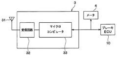
- FIG. 1 is a diagram illustrating an overall configuration of a tire pressure detection device to which a wheel position detection device according to a first embodiment of the present disclosure is applied.
- FIG. 2A is a diagram illustrating a block configuration of the transmitter 2.
- FIG. 2B is a diagram showing a block configuration of the TPMS-ECU 3.
- FIG. 3 is a timing chart for explaining wheel position detection.
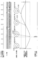
- FIG. 4 is an image diagram showing changes in gear information.
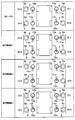
- FIG. 5A is a schematic diagram illustrating the wheel position determination logic.
- FIG. 5B is a schematic diagram illustrating the wheel position determination logic.
- FIG. 5C is a schematic diagram illustrating wheel position determination logic.
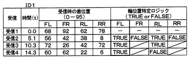
- FIG. 6A is a chart showing the evaluation result of the wheel position of ID1
- FIG. 6B is a chart showing the evaluation result of the wheel position of ID2
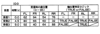
- FIG. 6C is a chart showing the evaluation result of the wheel position of ID3.
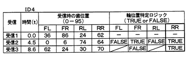
- FIG. 6D is a chart showing the evaluation results of the wheel position of ID4.
- FIG. 7 is a flowchart of registration start determination processing executed by the TPMS-ECU 3.
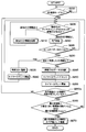
- FIG. 8 is a flowchart of the spare wheel registration process executed by the TPMS-ECU 3.
- FIG. 9 is a time chart when frames are received from spare wheels of the host vehicle and other vehicles.
- FIG. 10 is a time chart when frames are received from spare wheels of the host vehicle and other vehicles.
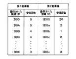
- FIG. 11 is a chart showing the relationship between the candidate ID registered and the number of receptions when the vehicle is parked in the first parking lot and then parked in the second parking lot after shifting to the registration mode.
- FIG. 12 is a flowchart of spare wheel registration processing executed by the TPMS-ECU 3 described in the second embodiment of the present disclosure.
- FIG. 1 is a diagram illustrating an overall configuration of a TPMS to which a wheel position detection device according to a first embodiment of the present disclosure is applied.
- the upper direction in the drawing of FIG. 1 corresponds to the front of the vehicle 1, and the lower direction of the drawing corresponds to the rear of the vehicle 1.
- TPMS in this embodiment is demonstrated.
- the TPMS is provided in the vehicle 1, and includes a transmitter 2, an ECU for TPMS (hereinafter referred to as TPMS-ECU) 3 serving as a receiver, and a meter 4. Yes.
- the wheel position detection device uses the transmitter 2 and TPMS-ECU 3 provided in the TPMS, and the wheels provided corresponding to the wheels 5 (5a to 5e) from the brake control ECU (hereinafter referred to as brake ECU) 10.
- the wheel position is specified by acquiring gear information obtained from detection signals of the speed sensors 11a to 11d.
- the transmitter 2 is attached to each of the wheels 5a to 5e including the traveling wheels 5a to 5d and the spare wheel 5e.
- the transmitter 2 detects the air pressure of the tires attached to the wheels 5a to 5e, and stores information related to the tire air pressure indicating the detection result in the frame together with the unique ID information of each transmitter 2 and transmits it.
- acceleration on data hereinafter referred to as G-ON data
- G-ON data acceleration off data
- G-OFF data is stored.
- G-ON data and G-OFF data correspond to data indicating the state of the acceleration sensor 22.
- the transmitter 2 has a function of detecting that the acceleration sensor 22 is turned on, and stores G-ON data or G-OFF data in a frame based on the detection result. Yes.
- the transmitter 2 is provided with a physical switch (not shown) in which a movable contact that is displaced according to acceleration in the centrifugal direction is in contact with a fixed contact. Is detected to have been turned on.
- the TPMS-ECU 3 is attached to the vehicle body 6 side of the vehicle 1 and receives the frame transmitted from the transmitter 2 and performs various processes and calculations based on the detection signal stored therein. Thus, wheel position detection and tire air pressure detection are performed.
- the transmitter 2 creates a frame by, for example, FSK (frequency shift keying), and the TPMS-ECU 3 demodulates the frame to read data in the frame to detect the wheel position and the tire air pressure.
- 2A and 2B show block configurations of the transmitter 2 and the TPMS-ECU 3.
- the transmitter 2 includes a sensing unit 21, an acceleration sensor 22, a microcomputer 23, a transmission circuit 24, and a transmission antenna 25, and supplies power from a battery (not shown). Each part is driven based on the above.
- the sensing unit 21 includes a diaphragm type pressure sensor 21a and a temperature sensor 21b, for example, and outputs a detection signal corresponding to the tire pressure and a detection signal corresponding to the temperature.
- the acceleration sensor 22 is used to detect the position of the sensor itself on the traveling wheels 5a to 5d to which the transmitter 2 is attached, that is, to detect the position of the transmitter 2 and the vehicle speed.
- the acceleration sensor 22 according to the present embodiment is, for example, the acceleration acting on the traveling wheels 5a to 5d when the traveling wheels 5a to 5d are rotated, in the radial direction of each traveling wheel 5a to 5d, that is, the acceleration in both directions perpendicular to the circumferential direction.
- a corresponding detection signal is output.
- the microcomputer 23 is a well-known one having a control unit (first control unit) and the like, and executes predetermined processing according to a program stored in a memory in the control unit.
- Individual ID information including identification information unique to the transmitter for identifying each transmitter 2 and identification information unique to the vehicle for identifying the host vehicle is stored in the memory in the control unit.
- the microcomputer 23 receives the detection signal related to the tire pressure from the sensing unit 21, processes the signal and processes it as necessary, and stores the information related to the tire pressure in the frame together with the ID information of each transmitter 2. .
- the microcomputer 23 monitors the detection signal of the acceleration sensor 22 to detect the position (angle detection) of the transmitter 2 on the traveling wheels 5a to 5d to which the transmitters 2 are attached, and to detect the vehicle speed. ing.
- the microcomputer 23 creates the frame, the microcomputer 23 transmits the frame (data transmission) from the transmission antenna 25 to the TPMS-ECU 3 via the transmission circuit 24 based on the position detection result of the transmitter 2 and the vehicle speed detection result. )I do.
- the microcomputer 23 starts frame transmission on the condition that the vehicle 1 is traveling, and at a timing at which the angle of the acceleration sensor 22 becomes a predetermined angle based on the detection signal of the acceleration sensor 22. Repeated frame transmission. Whether the vehicle is running is determined based on the vehicle speed detection result, and the angle of the acceleration sensor 22 is determined based on the position detection result of the transmitter 2 based on the detection signal of the acceleration sensor 22. .
- the microcomputer 23 detects the vehicle speed using the detection signal of the acceleration sensor 22, and determines that the vehicle 1 is running when the vehicle speed becomes a predetermined speed (for example, 5 km / h) or more.
- the output of the acceleration sensor 22 includes acceleration based on centrifugal force (centrifugal acceleration).
- the vehicle speed can be calculated by integrating the centrifugal acceleration and multiplying the coefficient. For this reason, the microcomputer 23 calculates the centrifugal acceleration by removing the gravitational acceleration component from the output of the acceleration sensor 22, and calculates the vehicle speed based on the centrifugal acceleration.
- the acceleration sensor 22 outputs a detection signal corresponding to the rotation of each of the traveling wheels 5a to 5d
- the gravitational acceleration component is included in the detection signal during traveling, and the amplitude corresponding to the wheel rotation.
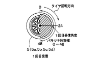
- a signal having For example, the amplitude of the detection signal is a negative maximum amplitude when the transmitter 2 is located at the upper position around the central axis of the traveling wheels 5a to 5d, zero when located at the horizontal position, and a position at the lower position. When it is, the maximum amplitude is positive.
- the position of the acceleration sensor 22 can be detected based on this amplitude, and the acceleration sensor 22 is located at an upper position around the angle of the position of the transmitter 2, for example, the central axis of each traveling wheel 5a to 5d.
- the angle formed by the acceleration sensor 22 when the time is 0 ° can be grasped.
- the frame transmission from each transmitter 2 is performed at the start timing when the acceleration sensor 22 reaches a predetermined angle at the same time when the vehicle speed reaches the predetermined speed or after the vehicle speed reaches the predetermined speed.
- the frame is transmitted repeatedly at the timing when the angle formed by the acceleration sensor 22 becomes the same angle as the first frame transmission.
- the angle formed by the acceleration sensor 22 may be the same as that at the time of the first frame transmission.
- the frame transmission is always performed every time the angle is reached. For example, it is preferable that frame transmission is performed only once in a predetermined time (for example, 15 seconds).
- the transmission circuit 24 functions as an output unit that transmits a frame transmitted from the microcomputer 23 to the TPMS-ECU 3 through the transmission antenna 25.
- frame transmission for example, radio waves in the RF band are used.
- the transmitter 2 configured in this manner is attached to an air injection valve in each of the wheels 5a to 5e, for example, and is arranged so that the sensing unit 21 is exposed inside the tire.
- the transmitter 2 detects the tire air pressure of the wheel to which the transmitter 2 is attached, and when the vehicle speed exceeds the predetermined speed as described above, the angle of the acceleration sensor 22 of each traveling wheel 5a to 5d becomes a predetermined angle.
- frame transmission is repeatedly performed through the transmission antenna 25 provided in each transmitter 2. After that, it is possible to transmit a frame from the transmitter 2 at the timing when the angle of the acceleration sensor 22 of each traveling wheel 5a to 5d becomes a predetermined angle.
- the mode is switched from the wheel position determination mode to the periodic transmission mode, and frame transmission is performed at a longer fixed period (for example, every minute), so that the TPMS-ECU 3 A signal related to tire pressure is periodically transmitted to the side.
- the transmission timing of each transmitter 2 can be shifted, and reception by the TPMS-ECU 3 side due to radio wave interference from a plurality of transmitters 2 is possible. It can be prevented from disappearing.
- the TPMS-ECU 3 is configured to include a receiving antenna 31, a receiving circuit 32, a microcomputer 33, and the like.
- the TPMS-ECU 3 is indicated by the number of teeth (or the number of teeth) of the gears rotated together with the traveling wheels 5a to 5d by acquiring gear information from the brake ECU 10 through an in-vehicle LAN such as CAN as will be described later. The tooth position is acquired.
- the receiving antenna 31 is for receiving a frame sent from each transmitter 2.
- the receiving antenna 31 is fixed to the vehicle body 6 and may be an internal antenna disposed in the main body of the TPMS-ECU 3, or may be an external antenna in which wiring is extended from the main body.
- the receiving circuit 32 functions as an input unit that receives a transmission frame from each transmitter 2 received by the receiving antenna 31 and sends the frame to the microcomputer 33.
- the receiving circuit 32 transmits the received signal to the microcomputer 33.
- the microcomputer 33 corresponds to a second control unit, and executes wheel position detection processing according to a program stored in a memory in the microcomputer 33. Specifically, the microcomputer 33 performs wheel position detection based on the relationship between the information acquired from the brake ECU 10 and the reception timing at which the transmission frame from each transmitter 2 is received. From the brake ECU 10, in addition to the wheel speed information of the traveling wheels 5a to 5d, the gear information of the wheel speed sensors 11a to 11d provided corresponding to the traveling wheels 5a to 5d is acquired at predetermined intervals (for example, 10 ms). is doing.
- Gear information is information indicating the tooth positions of gears (gears) that are rotated together with the traveling wheels 5a to 5d.
- the wheel speed sensors 11a to 11d are constituted by, for example, electromagnetic pickup sensors arranged to face the gear teeth, and change the detection signal as the gear teeth pass. Since these types of wheel speed sensors 11a to 11d output square pulse waves corresponding to the passage of teeth as detection signals, the rising and falling of the square pulse waves pass through the tooth edge of the gear. Will be expressed. Therefore, the brake ECU 10 counts the number of teeth of the gear, that is, the number of passing edges, from the number of rising and falling edges of the detection signals of the wheel speed sensors 11a to 11d, and the tooth edge at that time is counted every predetermined period. The number is transmitted to the microcomputer 33 as gear information indicating the tooth position. Thereby, in the microcomputer 33, it is possible to grasp which tooth of the gear has passed.
- the number of tooth edges is reset every time the gear rotates once. For example, when the number of teeth provided on the gear is 48 teeth, the number of edges is counted as a total of 96 from 0 to 95, and when the count value reaches 95, it is returned to 0 and counted again.
- the number of tooth edges of the gear is transmitted from the brake ECU 10 to the microcomputer 33 as gear information.
- the number of teeth may be a count value of the number of passing teeth.
- the number of edges or teeth passed during the predetermined period is transmitted to the microcomputer 33, and the microcomputer 33 adds the number of edges or teeth passed during the predetermined period to the previous number of edges or teeth. You may make it count the number of edges or the number of teeth in the period. That is, it is only necessary that the microcomputer 33 can finally acquire the number of edges or the number of teeth in the cycle as gear information.
- the brake ECU 10 resets the number of gear teeth (or the number of teeth) every time the power is turned off, but again starts measuring at the same time when the power is turned on or when the vehicle speed reaches the predetermined vehicle speed. ing. Thus, even if the power is turned off every time the power is turned off, the same teeth are represented by the same number of edges (or the number of teeth) while the power is turned on.
- the microcomputer 33 measures the reception timing when the frame transmitted from each transmitter 2 is received, and the frame reception timing is determined from the number of edges (or the number of teeth) of the acquired gear.
- the wheel position is detected based on the number of edges (or the number of teeth) of the gear. As a result, it is possible to perform wheel position detection that identifies which traveling wheel 5a to 5d each transmitter 2 is attached to. A specific method for detecting the wheel position will be described in detail later.
- the microcomputer 33 stores the ID information of each transmitter 2 in association with the position of each traveling wheel 5a to 5d to which each transmitter 2 is attached based on the result of wheel position detection. After that, based on the ID information stored in the transmission frame from each transmitter 2 and the data related to the tire pressure, the tire pressure of each of the traveling wheels 5a to 5d is detected, and an electric signal corresponding to the tire pressure is sent to the CAN. To the meter 4 through the in-vehicle LAN. For example, the microcomputer 33 detects a decrease in tire air pressure by comparing the tire air pressure with a predetermined threshold Th, and outputs a signal to that effect to the meter 4 when a decrease in tire air pressure is detected. Thus, the meter 4 is informed that the tire air pressure of any of the four traveling wheels 5a to 5d has decreased.
- the meter 4 functions as an alarm unit, and as shown in FIG. 1, is arranged at a place where the driver can visually recognize, and is configured by a meter display or the like installed in an instrument panel in the vehicle 1, for example. .
- a signal indicating that the tire air pressure has decreased is sent from the microcomputer 33 in the TPMS-ECU 3, the meter 4 displays the decrease in tire air pressure while identifying the traveling wheels 5 a to 5 d. Informs the driver of a decrease in tire pressure of a specific wheel.
- the microcomputer 23 monitors the detection signal of the acceleration sensor 22 at every predetermined sampling period based on the power supply from the battery, thereby determining the vehicle speed and the angle of the acceleration sensor 22 at each of the wheels 5a to 5e. Detected. Then, when the vehicle speed reaches a predetermined speed, the microcomputer 23 repeatedly transmits frames at a timing at which the angle of the acceleration sensor 22 becomes a predetermined angle. For example, frame transmission from each transmitter 2 is performed with a predetermined angle when the vehicle speed reaches a predetermined speed or a start timing when the acceleration sensor 22 reaches a predetermined angle after the vehicle speed reaches the predetermined speed. I have to. The frame is transmitted repeatedly at the timing when the angle formed by the acceleration sensor 22 becomes the same angle as the first frame transmission.
- the gear information of the wheel speed sensors 11a to 11d provided corresponding to the traveling wheels 5a to 5d is acquired from the brake ECU 10 every predetermined period (for example, 10 ms). Then, the TPMS-ECU 3 measures the reception timing when the frame transmitted from each transmitter 2 is received, and when the frame reception timing is selected from the number of gear edges (or the number of teeth). Get the number of gear edges (or the number of teeth).
- the reception timing of the frame transmitted from each transmitter 2 does not always coincide with the cycle of acquiring gear information from the brake ECU 10.
- the number of edges (or the number of teeth) of the gear indicated by the gear information acquired in the cycle closest to the reception timing of the frame among the cycles in which the gear information is acquired from the brake ECU 10, that is, the cycle immediately before or immediately after that Can be used as the number of gear edges (or the number of teeth).
- the frame reception timing is obtained by using the number of gear edges (or the number of teeth) indicated by the gear information acquired in the period immediately before and after the frame reception timing from the period in which the gear information is acquired from the brake ECU 10.
- the number of edges (or the number of teeth) of the gear may be calculated.
- the intermediate value of the number of gear edges (or the number of teeth) indicated by the gear information acquired immediately before and after the frame reception timing is used as the number of gear edges (or the number of teeth) at the frame reception timing. Can be used.
- the operation of obtaining the number of gear edges (or the number of teeth) at the reception timing of the frame is repeated every time the frame is received, and the number of gear edges (or the number of gear edges at the received frame reception timing)
- the wheel position is detected based on the number of teeth. Specifically, the variation in the number of gear edges (or the number of teeth) at the frame reception timing is within a predetermined range set based on the number of gear edges (or the number of teeth) at the previous reception timing.
- the wheel position is detected by determining whether or not there is.
- the tooth position indicated by the number of gear edges (or the number of teeth) at the frame reception timing Is almost the same as the previous time. For this reason, the variation in the number of edges (or the number of teeth) of the gears at the frame reception timing is small and falls within a predetermined range. This is true even when multiple frames are received, and the variation in the number of gear edges (or the number of teeth) at the reception timing of each frame is within a predetermined range determined at the first frame reception timing. It will fit.
- the tooth position indicated by the number of edges (or the number of teeth) of the gear at the reception timing of the frame transmitted from the transmitter 2 of the other wheel varies.
- the rotation of the gears of the wheel speed sensors 11a to 11d is linked to the traveling wheels 5a to 5d, the number of gear edges (or the number of teeth) at the reception timing of the frame for the wheel that has received the frame.
- the tooth positions indicated by are almost the same.
- the rotational state of the traveling wheels 5a to 5d varies depending on road conditions, turning or lane change, and therefore the traveling state of the traveling wheels 5a to 5d cannot be completely the same. For this reason, for a wheel that is different from the wheel that received the frame, the tooth position indicated by the number of gear edges (or the number of teeth) at the frame reception timing varies.
- the tooth position indicated by the number of gear edges (or the number of teeth) at the frame reception timing varies.
- the wheel position is detected by determining whether or not the variation is within a predetermined range.
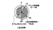
- the variation allowable width which is the allowable width for the number of gear edges (or the number of teeth), is a value corresponding to a range of 180 ° centered on the first reception angle (the range of the first reception angle ⁇ 90 °).
- the number of edges is a range of ⁇ 24 edges centered on the number of edges at the first reception
- the number of teeth is a range of ⁇ 12 teeth centered on the number of teeth at the first reception. In this case, as shown in FIG.
- the wheel having the number of edges (or the number of teeth) may coincide with the wheel on which the frame transmission is performed, and becomes TRUE (correct).
- the variation allowable width is determined around the second reception angle that is the angle of the transmitter 2 at the time of the second frame reception, and is equivalent to 180 ° ( ⁇ 90 °) around the second reception angle. Value. For this reason, a variation allowable width of 180 ° ( ⁇ 90 °) centered on the first reception angle that is the previous allowable variation width and a variation allowable width of 180 ° ( ⁇ 90 °) centered on the second reception angle
- the overlapping portion becomes a new variation allowable width (edge number range is 12 to 48), and the new variation allowable width can be narrowed to the overlapping range.
- the number of gear edges (or the number of teeth) is obtained at each reception timing of the frame, and the corresponding wheel is obtained. This is stored for each (left front wheel FL, right front wheel FR, left rear wheel RL, right rear wheel RR).
- a transmitter that transmits the frame out of the range is transmitted. 2 is excluded from the attached wheel candidates. And the wheel which was not excluded until the last is registered as a wheel with which the transmitter 2 with which the flame
- the right front wheel FR, the right rear wheel RR, and the left rear wheel RL are excluded from the candidates in this order, and the remaining left front wheel FL is finally attached to the transmitter 2 to which the frame is transmitted.
- the wheel is registered in association with the ID information.
- the microcomputer 33 stores the ID information of each transmitter 2 that has transmitted the frame in association with the position of the wheel to which it is attached.
- the TPMS-ECU 3 receives the frame transmitted when the vehicle speed reaches the predetermined speed, and stores the gear information at the reception timing. However, the TPMS-ECU 3 stores a predetermined traveling stop determination speed (for example, 5 km). / H) When it becomes below, the gear information so far is discarded. When the vehicle starts running again, the wheel position is newly detected as described above.
- the basic wheel position detection is performed by the above method. This makes it possible to detect the wheel positions of the left front wheel FL, the right front wheel FR, the left rear wheel RL, and the right rear wheel RR, which are the traveling wheels 5a to 5d.
- ID information that is a candidate for registration of ID information stored in the frame (hereinafter referred to as candidate ID) can be.
- candidate ID ID information that is a candidate for registration of ID information stored in the frame.
- the timing at which the frame transmitted from the transmitter of the other vehicle is received does not match the tooth position of the gear of any wheel of the own vehicle. For this reason, it can avoid registering the ID information of the transmitter of another vehicle, and can register only the ID information of the transmitter 2 of the own vehicle.
- the ID information of the transmitter of the other vehicle can also be a candidate ID.
- the ID information of the transmitter can also be a candidate ID.
- the ID information is only included when the tooth position at the frame reception timing is included in the variation allowable range continuously for a predetermined number of times (for example, 10 times). Is registered.
- the number of gear edges (or teeth) acquired at each frame reception timing is also received for that frame, as in the case of the host vehicle. It is determined whether or not (number) is within the range of variation tolerance. And, similarly to the transmitter 2 of the own vehicle, for the frame transmitted from the transmitter of the other vehicle, the wheel that is out of the range of the allowable variation range is selected from the wheel candidates attached to the transmitter 2 to which the frame is transmitted. Will be excluded. At this time, since the elimination method is used, at the time when only one wheel is finally left without being excluded in each frame, the wheel candidate to which the transmitter 2 to which the wheel transmits the frame is attached. It becomes.
- the ID information of the transmitter attached to the wheels of the other vehicle is erroneously registered as that of the own vehicle.
- the frames transmitted from the transmitters attached to the wheels of the other vehicle are not of the own vehicle, and thus are likely to vary, and are transmitted from the transmitter 2 attached to the traveling wheels 5a to 5d of the own vehicle. It tends to be excluded from wheel candidates earlier than the frame. For this reason, most of the frames transmitted from the transmitters of the wheels of other vehicles are identified as wheel candidates that are attached to the transmitters that transmitted the frames. It is easy to become the state that was done.
- the ID information registration condition is that the tooth position at the reception timing of the frame is continuously included within the tolerance range after the wheel is specified, the other vehicle is in the meantime.
- the tooth position of the reception timing of the frame from the transmitter is out of the tolerance range. Therefore, it is possible to prevent the ID information of the transmitter attached to the wheels of the other vehicle from being erroneously registered as that of the own vehicle.
- the wheel positions of the left front wheel FL, the right front wheel FR, the left rear wheel RL, and the right rear wheel RR that are the traveling wheels 5a to 5d can be detected by the above-described method.
- the process for specifying the spare wheel 5e is further performed.
- the TPMS-ECU 3 determines whether or not there is data indicating the state of the acceleration sensor 22 stored in the received frame and the traveling history of the host vehicle, and based on the determination result and the like.
- the ID information of the transmitter 2 of the spare wheel 5e in the vehicle is also registered.
- the spare wheel registration process executed by TPMS-ECU 3 will be described. This process is performed together with the wheel position detection process of the traveling wheels 5a to 5d described above. For example, when a power switch is turned on to turn on the TPMS-ECU 3 when the wheel position detection execution switch (not shown) is operated, the TPMS-ECU 3 enters the ID registration mode. Then, this processing is executed every predetermined control period together with the wheel position detection processing of the traveling wheels 5a to 5d.
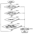
- the registration start determination process shown in FIG. 7 is executed to determine whether or not it is necessary to shift to the ID registration mode.
- the spare wheel registration process shown in FIG. 8 is performed. By executing, the wheel position detection is performed while leaving only the candidate ID that should be truly left. Note that the processing shown in FIGS. 7 and 8 is executed at predetermined control cycles when, for example, the TPMS-ECU 3 is turned on by turning on the IG.
- steps 100 to 130 it is determined whether or not the situation where the transition to the ID registration mode is required has been made.
- step 100 it is determined whether or not a request for shifting to the ID registration mode has been issued through an external tool (not shown) that instructs execution of wheel position detection.
- the external tool for example, transmits a command for requesting transition to the ID registration mode to the TPMS-ECU 3, and transmits the command to the TPMS-ECU 3 through the in-vehicle LAN such as CAN even if the command is transmitted to the TPMS-ECU 3 using radio waves. It may be a thing.
- step 110 it is determined whether or not a request for shifting to the ID registration mode has been issued by operating a wheel position detection execution switch (not shown).
- a wheel position detection execution switch is provided on, for example, an instrument panel. When the execution switch is operated by a user, it is transmitted to the TPMS-ECU 3 through an in-vehicle LAN such as CAN.
- step 120 it is determined whether or not the ID information of the transmitter 2 of each wheel 5a to 5d is in an unregistered state. For example, immediately after the vehicle manufacture is completed, the ID information of any transmitter 2 is still unregistered, and it is necessary to detect the wheel position.
- step 130 it is determined whether or not it is assumed that the tire has been changed based on the comparison of the number of times of reception of the registered ID information and the unregistered ID information. Even in such a case, it is necessary to detect the wheel position. For example, it is determined that the tire replacement or the like is assumed when the number of times of reception of the unregistered ID information is more than a predetermined number of times than the registered ID information.
- step 140 the process proceeds to the ID registration mode, and the process is terminated. Return and repeat the above process. In this way, the registration start determination process for determining whether to start the registration of the ID information of the transmitter 2 of the host vehicle by detecting the wheel position is completed.
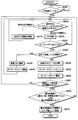
- step 200 it is first determined in step 200 whether or not the ID registration mode is set. If the transition to the ID registration mode has been performed in step 140 of FIG. 7 described above, an affirmative determination is made in this step and the routine proceeds to step 205.
- Step 205 it is determined whether or not there is a candidate ID whose timer count value is equal to or longer than a predetermined time (for example, 10 minutes).
- the count value of the timer here is a count value after the timer count is started in Steps 240 and 255 described later, and is counted for each candidate ID, and a frame including each candidate ID is received last time. It represents the elapsed time from.
- the transmission interval of frames from the transmitter 2 is basically determined although it varies depending on the situation. For example, during a period in which wheel position detection may be performed, such as when the vehicle starts to travel, the wheel position determination mode is set and the frame transmission interval is relatively short. Further, when the time assumed to be necessary for wheel position detection elapses, the mode is switched to the regular transmission mode, and frame transmission is performed at a longer fixed period. Further, when the vehicle is stopped, there may be a case where a transmission mode during stopping that sets a transmission cycle longer than that of the regular transmission mode is provided and frame transmission is performed every longer fixed cycle. However, in any of these modes, frame transmission is performed within a certain period, and frame reception is performed on the TPMS-ECU 3 side.
- the system has a specification that a frame transmitted from the transmitter 2 of the own vehicle is received at least once within a predetermined time, and in some countries, this is obligated by laws and regulations. For example, it is specified that a frame transmitted from the transmitter 2 of the own vehicle is received during a predetermined period of 20 minutes in North America and 10 minutes in Europe.
- the frame transmitted from each transmitter 2 of the host vehicle is received by the TPMS-ECU 3, and for candidate IDs not received during the predetermined period, transmission of the host vehicle is performed. It can be determined that the ID information is not the machine 2.
- step 205 when it is determined in step 205 that there is a corresponding ID as described above, the process proceeds to step 210 to delete the corresponding ID from the candidate IDs, and then the process returns to step 205.
- step 205 determines whether there is no corresponding ID. If it is determined in step 205 that there is no corresponding ID, the process proceeds to step 220. Then, when a frame transmitted as RF reception, that is, a radio wave in the RF band, is received, the processing after step 225 is executed.
- step 225 it is determined whether G-OFF data is stored as data indicating the state of the acceleration sensor 22 in the received frame. That is, it is determined whether or not the acceleration sensor 22 provided in the transmitter 2 that has transmitted the received frame is in an on state.
- the traveling wheels 5a to 5d when the host vehicle is traveling, if the wheel speed of the traveling wheels 5a to 5d reaches a predetermined speed, the frame of the transmitter 2 attached to the traveling wheels 5a to 5d is displayed. Stores G-ON data. However, in the case of the spare wheel 5e, even if the vehicle is running, it cannot be rotated, and therefore G-OFF data is stored in the frame of the transmitter 2 attached to the spare wheel 5e. Therefore, when the G-OFF data is stored in the received frame, the received frame may be transmitted from the transmitter 2 of the spare wheel 5e. Therefore, if an affirmative determination is made in this step, the process proceeds to step 230 and thereafter, and if a negative determination is made, the process returns to step 205.
- step 230 it is determined whether or not the ID information stored in the currently received frame is the ID received for the first time. If the determination is affirmative, the process proceeds to step 235 and is registered as a candidate ID. Then, the process proceeds to step 240, and the timer count for the candidate ID is started.
- step 230 if a negative determination is made in step 230, since the ID information stored in the frame received this time has already been registered as a candidate ID, the process proceeds to step 245 to receive a registered candidate ID. Add a number.
- step 250 the timer count for the candidate ID is once reset, and then the process proceeds to step 255 to start the timer count for the candidate ID. Thereby, the timer count for the candidate ID is performed again from the beginning.
- step 260 it is determined whether or not there is a travel history after shifting to the registration mode.
- the predetermined period here is set to a frame transmission cycle of the transmitter 2 of the spare wheel 5e, that is, a time longer than the transmission cycle longer than in the regular transmission mode, and the frame transmitted from the transmitter 2 of the spare wheel 5e. Is set to a time at which the receiver 3 receives at least once.
- Whether or not the vehicle state is running is determined by obtaining vehicle speed data from the brake ECU 10 because the brake ECU 10 performs vehicle speed calculation based on detection signals from the wheel speed sensors 11a to 11d. be able to.
- the candidate ID When there is a travel history after shifting to the registration mode, the candidate ID is basically registered in a situation where there is no specific vehicle around. For this reason, it is considered that the frame is received from the transmitter 2 of the spare wheel 5e, and the ID information of the transmitter 2 of the spare wheel 5e in the host vehicle is already registered in the candidate ID.
- a candidate ID is registered in a situation where a specific vehicle exists around.
- a candidate ID may be registered in a situation where a plurality of vehicles are parked around such as a parking lot or waiting for a signal.
- the ID information of the transmitter of the wheel of the other vehicle may be registered in the candidate ID and reach the memory capacity. There is sex. In such a case, there is a possibility that the ID information of the transmitter 2 of the spare wheel 5e in the own vehicle cannot be registered in the candidate ID.
- step 260 it is determined whether or not there is a travel history after shifting to the registration mode. If the determination is affirmative, the ID information of the transmitter 2 of the spare wheel 5e in the host vehicle is already registered in the candidate ID. If not, the process proceeds to step 265. If a negative determination is made in step 260, the ID information of the transmitter 2 of the spare wheel 5e in the own vehicle may not be registered in the candidate ID, and the process returns to step 205.
- step 260 If a negative determination is made in step 260 as described above, the frame including the ID information once registered as the candidate ID will not be received when the vehicle travels thereafter. It is determined that there is ID information. As a result, the ID information of the transmitters of other vehicles can be excluded and the memory capacity can be made free. Thereby, even if the ID information of the transmitter 2 of the spare wheel 5e in the host vehicle is not registered in the candidate ID, it is registered as a candidate ID due to the vacant memory capacity.
- step 265 it is determined whether the received frame is the transmitter 2 of the spare wheel 5e in the own vehicle or the transmitter of another vehicle. If the frame is transmitted from the transmitter 2 of the spare wheel 5e in the host vehicle, the ID information of the frame is registered as that of the spare wheel 5e.
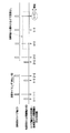
- step 265 it is determined whether or not the difference between the maximum number of receptions and the second largest number of receptions is 3 or more and the maximum number of receptions is 4 or more. Thereby, it is determined whether the received frame is the transmitter 2 of the spare wheel 5e in the own vehicle or the transmitter of the other vehicle. This will be described with reference to time chart examples shown in FIGS.
- the frame When the vehicle state of the host vehicle is running and the G-OFF data is stored in the received frame, the frame is basically attached to the spare wheel 5e in the host vehicle.
- a transmitter 2 is assumed. However, there may be a case where the frame is not transmitted by the transmitter 2 of the spare wheel 5e in the own vehicle. For example, when there is another vehicle running side by side with the host vehicle, there is a possibility that the frame is transmitted from a spare wheel transmitter of the other vehicle. Further, when another vehicle or wheel is loaded on the host vehicle, there is a possibility that the frame is transmitted from a wheel of another vehicle being loaded or a transmitter of the loaded wheel.
- the loaded other vehicle or loaded wheel is separated from the own vehicle, so that the frame transmitted from the loaded vehicle wheel or loaded wheel transmitter cannot be received. For this reason, there is a difference in the number of received frames, and a frame with a large number of received frames is transmitted from the transmitter 2 of the spare wheel 5e in the host vehicle. It can be determined that it is transmitted from the transmitter of the loading wheel.
- a frame transmitted from the transmitter 2 of the spare wheel 5e in the host vehicle and a frame transmitted from the transmitter of the other vehicle or the loaded wheel are transmitted at predetermined frame transmission timings (for example, at intervals of 96 s). ).
- the transmitter 2 normally performs acceleration detection or the like at a low frequency (for example, at intervals of 16 s) in order to suppress current consumption.
- the acceleration sensor 22 is not in an on state, the frequency is even lower than normal (for example, at an interval of 96 s). Acceleration detection and so on are performed.
- the frame transmitted from the transmitter 2 of the spare wheel 5e has not been received yet when the frame transmitted from the transmitter of the other vehicle or the loaded wheel is received immediately.
- the difference between the maximum received number and the second most received number is that the number of received frames transmitted from the transmitter 2 of the spare wheel 5e is 0 and the frame transmitted from the transmitter of the other vehicle or the loaded wheel Since the number of reception is 1, it is 1.
- the difference between the maximum received number and the second most received number is the reception of the frame transmitted from the transmitter 2 of the spare wheel 5e.
- the number is 1, and the number of received frames transmitted from the transmitter of the other vehicle or the loaded wheel is 1, so it is 0.
- the difference between the maximum reception number and the second most reception number is finally 3 or more, and it can be determined that the ID information of the frame with the maximum reception number is the ID information of the transmitter 2 of the spare wheel 5e.
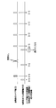
- the difference between the maximum reception number and the second most reception number is 2 or more, it is determined that the ID information of the frame with the maximum reception number is the ID information of the transmitter 2 of the spare wheel 5e.
- the frame transmitted from the transmitter 2 of the spare wheel 5e may not be received by the TPMS-ECU 3 due to data collision during transmission or interference of disturbing radio waves.
- the difference between the maximum received number and the second most received number is 2. End up.
- the difference between the maximum received number and the second most received number is 3 or more, it is determined that the ID information of the frame with the maximum received number is the ID information of the transmitter 2 of the spare wheel 5e. .
- the ID information of the transmitter of the loaded other vehicle or the loaded wheel is mistakenly registered as the ID information of the transmitter 2 of the spare wheel 5e in the own vehicle due to the data missing once.
- the shorter the transmission timing the more likely data collision occurs, and there is a possibility that the frame transmitted by the transmitter of the spare wheel 5e cannot be received by the TPMS-ECU3. It is effective to set the difference from the large number of receptions to 3 or more.
- step 265 it is also determined that the maximum number of receptions is 4 or more.
- the maximum number of receptions is set to 4 or more.
- the higher the lower limit value the better the reliability.
- the lower limit value of the maximum number of receptions is set to 4 times here.
- this determination item for the maximum number of receptions is not an indispensable item in the determination in step 265, and only the difference between the maximum reception number and the second most reception number may be used as the determination item.
- step 265 it is determined that there is a difference between the maximum received number and the second most received number. Then, when an affirmative determination is made in step 265, the process proceeds to step 270, and the ID information of the frame with the maximum number of receptions is registered as the ID information of the transmitter 2 of the spare wheel 5e in the host vehicle, thereby transmitting the spare wheel 5e. Registration of the ID information of the machine 2 is completed.
- the tire air pressure is detected. Specifically, at the time of tire pressure detection, a frame is transmitted from each transmitter 2 at regular intervals, and every time a frame is transmitted from each transmitter 2, four traveling wheels and spare wheels are transmitted. The frame is received by the TPMS-ECU 3. Then, the TPMS-ECU 3 identifies which frame is sent from the transmitter 2 attached to the wheels 5a to 5e based on the ID information stored in each frame, and determines each frame from information related to the tire pressure. The tire pressure of the wheels 5a to 5e is detected.
- the spare wheel 5e is excluded from the notification target when the tire pressure decreases because the tire pressure does not hinder even if the tire pressure is decreased, and the tire pressure of the traveling wheels 5a to 5d is matched. Only a decrease in tire air pressure may be reported.
- the tooth positions of the gears 12a to 12d are shown based on the detection signals of the wheel speed sensors 11a to 11d that detect the passage of the teeth of the gears 12a to 12d rotated in conjunction with the wheels 5a to 5d. Gear information is acquired every predetermined period. And if the variation allowable width is set based on the tooth position at the reception timing of the frame and the tooth position at the reception timing of the frame after setting the variation allowable width is outside the range of the variation allowable width, The wheel is excluded from the wheel candidates attached to the transmitter 2 to which the frame is transmitted, and the remaining wheels are registered as wheels to which the transmitter 2 to which the frame is transmitted is attached. For this reason, the wheel positions of the traveling wheels 5a to 5d can be specified even if a large amount of data is not available.
- spare wheel registration processing it is determined whether or not G-OFF data is stored when the vehicle state is traveling, and only ID information of a frame in which G-OFF data is stored during traveling is used as a spare wheel. Register as a candidate ID of 5e. And ID information of spare wheel 5e is specified from this registration ID. Specifically, after the transition to the registration mode, it is confirmed that there is a traveling history, and only when there is a traveling history, the frame of the own vehicle and that of the other vehicle are selected from the frames storing the G-OFF data. It is made to discriminate. For example, it is determined whether the difference between the maximum number of received frames in which G-OFF data is stored and the second most received number is a predetermined number (eg, 3) or more.
- a predetermined number eg, 3
- the ID information of the transmitter 2 of the spare wheel 5e in the own vehicle is not registered in the candidate ID due to the memory capacity being full or the like, the ID information of the spare wheel 5e is determined. I can not. Accordingly, it is possible to prevent the ID information of the transmitter of the surrounding vehicle, the loaded other vehicle, or the loaded wheel from being erroneously registered as the ID information of the transmitter 2 of the spare wheel 5e in the own vehicle.
- the ID information of the transmitter 2 of the traveling wheels 5a to 5d and the spare wheel 5e can be registered in this way, it is not necessary to provide an antenna for each wheel, and the number of parts increases due to the need for additional parts. As a result, high costs can be avoided.
- step 260 the spare wheel registration process is executed in the present embodiment as in the first embodiment. However, instead of step 260, the processing of step 260a is performed.
- step 260a it is determined whether or not the identification information of the traveling wheels 5a to 5d has been specified.
- the identification of the ID information of the traveling wheels 5a to 5d is not completed if there is no traveling history after shifting to the registration mode. For this reason, the completion of the identification of the ID information of the traveling wheels 5a to 5d is one of results obtained when there is a traveling history after shifting to the registration mode. Therefore, if an affirmative determination is made in step 260a, the processing proceeds to step 265 and the subsequent steps and the same processing as in the first embodiment is performed.
- the criteria for determining whether or not there is a travel history in step 260 of FIG. 8 described in the first embodiment may be changed as appropriate.
- the travel history after the transition to the registration mode based on the event that occurs as a result of the travel history after the transition to the registration mode. It can be determined whether or not there is.
- another determination criterion can be used, such as the fact that there is a travel history when the travel distance after shifting to the registration mode reaches a predetermined distance.
- the variation allowable width is changed at each frame reception timing, and the variation allowable width is gradually reduced. did.
- other methods may be used for the wheel position detection method on the traveling wheels 5a to 5d side.
- the variation allowable width is changed at each frame reception timing so that the variation allowable width is gradually narrowed.
- the variation allowable width set around the tooth position is constant. .
- the variation allowable width set around this tooth position can also be changed.
- the variation in the tooth position may increase as the vehicle speed increases. For this reason, it is possible to set a more accurate variation allowable width by increasing the variation allowable width as the vehicle speed increases.
- the longer the sampling period when the acceleration sensor 22 performs acceleration detection the lower the timing detection accuracy when the angle of the acceleration sensor 22 becomes a predetermined angle, and therefore the variation tolerance is changed accordingly.
- a more accurate variation tolerance can be set. In that case, since the transmitter 2 knows the sampling period and the like, the frame transmitted by the transmitter 2 can be transmitted including data for determining the variation allowable width.
- the angle at which frame transmission is performed is that the position where the angle is 0 ° is when the acceleration sensor 22 is positioned above the center axis of each wheel 5a to 5d.
- this is merely an example, and an arbitrary position in the circumferential direction of the wheel may be set to 0 °.
- the TPMS-ECU 3 acquires the gear information from the brake ECU 10. However, since it is sufficient that the TPMS-ECU 3 can acquire the number of teeth or the number of teeth of the gear as the gear information, it may be acquired from another ECU, or the detection signals of the wheel speed sensors 11a to 11d are input, The number of teeth or the number of teeth of the gear may be acquired from the detection signal.
- the case where the TPMS-ECU 3 and the brake ECU 10 are configured as separate ECUs has been described, but there may be a case where they are configured as a single ECU in which these are integrated.
- the ECU directly inputs the detection signals of the wheel speed sensors 11a to 11d, and acquires the number of teeth or the number of teeth of the gear from the detection signals.
- the number of teeth or the number of teeth of the gear can always be obtained, unlike the case where these pieces of information are obtained every predetermined period, based on the gear information exactly at the reception timing of the frame. Wheel position detection can be performed.
- the wheel position detection device provided for the vehicle 1 provided with the traveling wheels 5a to 5d and the spare wheel 5e has been described.
- the vehicle has a larger number of traveling wheels and spare wheels.
- the present disclosure can be applied.
- the wheel speed sensors 11a to 11d can detect the passage of gear teeth that are rotated in conjunction with the rotation of the wheels 5a to 5d. For this reason, as a gear, what is necessary is just the structure from which the magnetic resistance differs in which the part located in between the tooth
- the outer edge portion is made uneven so that the outer peripheral surface is not only a general structure composed of a convex portion that becomes a conductor and a space that becomes a nonconductor, but, for example, the outer peripheral surface becomes a conductor and a nonconductor
- a rotor switch made of an insulator is also included (see, for example, Japanese Patent Laid-Open No. 10-048233).
- the steps shown in each figure correspond to a device that executes various processes. That is, the part that executes the process of step 225 performs the first determination apparatus, the part that executes the process of step 260 performs the second determination apparatus, the part that executes the process of step 230 performs the third determination apparatus, and the process of step 265
- the part to perform corresponds to the fourth determination device.
- the part that executes the process of step 235 corresponds to the candidate registration apparatus
- the part that executes the process of step 245 corresponds to the received number adding apparatus
- the part that executes the process of step 270 corresponds to the registration apparatus.
- each section is expressed as S100, for example.
- each section can be divided into a plurality of subsections, while a plurality of sections can be combined into one section.
- each section configured in this manner can be referred to as a device, module, or means.
Abstract
Le dispositif de détection de position de roue selon l'invention est équipé des éléments suivants : un émetteur (2) qui est situé sur chaque roue d'un véhicule (1) et qui comprend un capteur d'accélération (22) de la roue et une première unité de commande (23) qui transmet une trame comprenant des informations d'identification ; et un récepteur (3) qui est situé sur la carrosserie du véhicule et qui comprend une seconde unité de commande (33) qui associe et enregistre les roues avec les informations d'identification. La première unité de commande détecte que la vitesse de roue a atteint une vitesse prédéterminée et stocke les données du capteur d'accélération dans la trame. La seconde unité de commande est équipée des éléments suivants : un premier dispositif de détermination (S225) qui détermine si oui ou non les conditions dans lesquelles le capteur d'accélération n'est pas dans la position MARCHE (ON) sont remplies ; un dispositif d'enregistrement de candidat (S235) qui enregistre les informations d'identification en tant que candidat pour les informations d'identification d'une roue de secours si les conditions sont remplies ; un second dispositif de détermination (S260) qui détermine l'historique de déplacement du véhicule ; et un dispositif d'enregistrement (S270) qui identifie les informations d'identification de la roue de secours et enregistre les informations d'identification en association avec la roue de secours si l'historique de déplacement est disponible.
Priority Applications (3)
| Application Number | Priority Date | Filing Date | Title |
|---|---|---|---|
| US15/575,006 US10214060B2 (en) | 2015-06-04 | 2016-05-10 | Wheel position detection device and tire-pressure detection system equipped with same |
| CN201680021237.5A CN107531114A (zh) | 2015-06-04 | 2016-05-10 | 车轮位置检测装置以及具备其的轮胎压力检测系统 |
| DE112016002494.0T DE112016002494T5 (de) | 2015-06-04 | 2016-05-10 | Radpositions-erfassungsvorrichtung und reifendruck-erfassungssystem, das mit der radpositions-erfassungsvorrichtung ausgestattet ist |
Applications Claiming Priority (2)
| Application Number | Priority Date | Filing Date | Title |
|---|---|---|---|
| JP2015-114240 | 2015-06-04 | ||
| JP2015114240A JP2017001416A (ja) | 2015-06-04 | 2015-06-04 | 車輪位置検出装置およびそれを備えたタイヤ空気圧検出システム |
Publications (1)
| Publication Number | Publication Date |
|---|---|
| WO2016194306A1 true WO2016194306A1 (fr) | 2016-12-08 |
Family
ID=57440361
Family Applications (1)
| Application Number | Title | Priority Date | Filing Date |
|---|---|---|---|
| PCT/JP2016/002293 WO2016194306A1 (fr) | 2015-06-04 | 2016-05-10 | Dispositif de détection de position de roue et système de détection de pression de pneu équipé de ce dernier |
Country Status (5)
| Country | Link |
|---|---|
| US (1) | US10214060B2 (fr) |
| JP (1) | JP2017001416A (fr) |
| CN (1) | CN107531114A (fr) |
| DE (1) | DE112016002494T5 (fr) |
| WO (1) | WO2016194306A1 (fr) |
Families Citing this family (11)
| Publication number | Priority date | Publication date | Assignee | Title |
|---|---|---|---|---|
| US9225307B2 (en) * | 2012-06-28 | 2015-12-29 | Sonos, Inc. | Modification of audio responsive to proximity detection |
| DE102016214865A1 (de) * | 2016-08-10 | 2018-02-15 | Continental Automotive Gmbh | Elektronische Radeinheit für ein Fahrzeugrad, sowie Verfahren zum Betreiben einer derartigen elektronischen Radeinheit |
| JP6617219B2 (ja) * | 2017-03-28 | 2019-12-11 | 太平洋工業株式会社 | 送信機、受信機、及び、送受信システム |
| JP6848601B2 (ja) * | 2017-03-29 | 2021-03-24 | 横浜ゴム株式会社 | 情報表示装置、情報表示システム、情報出力方法および制御プログラム |
| JP6477966B1 (ja) * | 2018-04-20 | 2019-03-06 | 株式会社デンソー | 車輪登録装置およびそれを備えたタイヤ空気圧監視システム |
| GB2573291B (en) * | 2018-04-30 | 2020-09-02 | Schrader Electronics Ltd | Methods and apparatus for determining the orientation of a tire mounted device |
| EP3741588B1 (fr) * | 2019-05-23 | 2023-03-01 | Melexis Technologies SA | Acquisition de données de surface de contact |
| EP3741587B1 (fr) | 2019-05-23 | 2023-09-27 | Melexis Technologies SA | Localisation automatique à l'aide d'un système monté sur pneu |
| CN111845218B (zh) * | 2020-06-15 | 2022-04-26 | 东风柳州汽车有限公司 | 一种基于车桥一侧为双胎的整车轮胎位置自动定位系统 |
| KR20220150961A (ko) * | 2020-11-19 | 2022-11-11 | 다이헤요 고교 가부시키가이샤 | 수신기, 송신기 및 송수신 시스템 |
| US11787242B2 (en) * | 2021-01-29 | 2023-10-17 | Sensata Technologies, Inc. | System and method for compensating transmission delays in tire pressure monitoring system |
Citations (2)
| Publication number | Priority date | Publication date | Assignee | Title |
|---|---|---|---|---|
| JP2006015955A (ja) * | 2004-07-05 | 2006-01-19 | Honda Motor Co Ltd | タイヤ空気圧監視システムおよびタイヤ空気圧監視方法 |
| JP2015051746A (ja) * | 2013-09-09 | 2015-03-19 | 株式会社東海理化電機製作所 | タイヤid登録システム |
Family Cites Families (17)
| Publication number | Priority date | Publication date | Assignee | Title |
|---|---|---|---|---|
| DE4205911A1 (de) | 1992-02-26 | 1993-09-02 | Uwatec Ag | Kontrollvorrichtung fuer den luftdruck von luftbereiften fahrzeugraedern |
| JP2000071726A (ja) | 1998-08-27 | 2000-03-07 | Pacific Ind Co Ltd | タイヤ空気圧警報システム |
| DE69917997T2 (de) | 1998-08-25 | 2005-06-09 | Pacific Industrial Co., Ltd., Ogaki | System zur Luftdruckkontrolle von Reifen |
| GB0203230D0 (en) | 2002-02-12 | 2002-03-27 | Lucas Industries Ltd | Tyre pressure monitor system |
| JP4000891B2 (ja) * | 2002-04-12 | 2007-10-31 | トヨタ自動車株式会社 | タイヤ状態取得装置 |
| JP3661670B2 (ja) | 2002-08-26 | 2005-06-15 | 株式会社デンソー | タイヤ空気圧監視システム、タイヤ空気圧監視装置、及びタイヤ空気圧監視プログラム |
| JP4389571B2 (ja) * | 2003-12-08 | 2009-12-24 | トヨタ自動車株式会社 | 車輪情報取得装置 |
| JP2006015895A (ja) | 2004-07-02 | 2006-01-19 | Nissan Motor Co Ltd | タイヤ空気圧モニター装置 |
| JP4631746B2 (ja) * | 2006-03-02 | 2011-02-16 | 株式会社デンソー | 車輪位置検出装置およびそれを備えたタイヤ空気圧検出装置 |
| JP4858034B2 (ja) * | 2006-09-19 | 2012-01-18 | 株式会社デンソー | 車輪位置検出装置およびそれを備えたタイヤ空気圧検出装置 |
| US7854163B2 (en) * | 2007-05-07 | 2010-12-21 | Denso Corporation | Wheel identifying apparatus and tire inflation pressure detecting apparatus with function of wheel identification |
| US8072319B2 (en) * | 2008-05-05 | 2011-12-06 | GM Global Technology Operations LLC | System and method for identifying a spare wheel |
| JP5585595B2 (ja) | 2012-01-18 | 2014-09-10 | 株式会社デンソー | 車輪位置検出装置およびそれを備えたタイヤ空気圧検出装置 |
| DE102012110689A1 (de) * | 2012-11-08 | 2014-05-08 | Huf Hülsbeck & Fürst Gmbh & Co. Kg | Verfahren zum Zuordnen von Reifendruckkontrollvorrichtungen zu den verschiedenen Positionen einer Anzahl von Rädern eines Fahrzeugs |
| JP6375970B2 (ja) | 2015-01-28 | 2018-08-22 | 株式会社デンソー | 車輪位置検出装置およびそれを備えたタイヤ空気圧検出システム |
| JP2016137842A (ja) | 2015-01-28 | 2016-08-04 | 株式会社デンソー | 車輪位置検出装置およびそれを備えたタイヤ空気圧検出システム |
| JP6507675B2 (ja) * | 2015-01-28 | 2019-05-08 | 株式会社デンソー | 車輪位置検出装置およびそれを備えたタイヤ空気圧検出システム |
-
2015
- 2015-06-04 JP JP2015114240A patent/JP2017001416A/ja active Pending
-
2016
- 2016-05-10 WO PCT/JP2016/002293 patent/WO2016194306A1/fr active Application Filing
- 2016-05-10 US US15/575,006 patent/US10214060B2/en not_active Expired - Fee Related
- 2016-05-10 DE DE112016002494.0T patent/DE112016002494T5/de not_active Withdrawn
- 2016-05-10 CN CN201680021237.5A patent/CN107531114A/zh active Pending
Patent Citations (2)
| Publication number | Priority date | Publication date | Assignee | Title |
|---|---|---|---|---|
| JP2006015955A (ja) * | 2004-07-05 | 2006-01-19 | Honda Motor Co Ltd | タイヤ空気圧監視システムおよびタイヤ空気圧監視方法 |
| JP2015051746A (ja) * | 2013-09-09 | 2015-03-19 | 株式会社東海理化電機製作所 | タイヤid登録システム |
Also Published As
| Publication number | Publication date |
|---|---|
| DE112016002494T5 (de) | 2018-02-22 |
| JP2017001416A (ja) | 2017-01-05 |
| US20180134102A1 (en) | 2018-05-17 |
| US10214060B2 (en) | 2019-02-26 |
| CN107531114A (zh) | 2018-01-02 |
Similar Documents
| Publication | Publication Date | Title |
|---|---|---|
| WO2016194306A1 (fr) | Dispositif de détection de position de roue et système de détection de pression de pneu équipé de ce dernier | |
| JP5585595B2 (ja) | 車輪位置検出装置およびそれを備えたタイヤ空気圧検出装置 | |
| JP5477368B2 (ja) | 車輪位置検出装置およびそれを備えたタイヤ空気圧検出装置 | |
| WO2016121364A1 (fr) | Dispositif de détection de position de roue et système de surveillance de la pression des pneus | |
| JP5585597B2 (ja) | 車輪位置検出装置およびそれを備えたタイヤ空気圧検出装置 | |
| JP5585596B2 (ja) | 車輪位置検出装置およびそれを備えたタイヤ空気圧検出装置 | |
| JP5477369B2 (ja) | 車輪位置検出装置およびそれを備えたタイヤ空気圧検出装置 | |
| JP5609860B2 (ja) | 車輪位置検出装置およびそれを備えたタイヤ空気圧検出装置 | |
| JP2013159265A (ja) | 車輪位置検出装置およびそれを備えたタイヤ空気圧検出装置 | |
| JP6372226B2 (ja) | 車輪位置検出装置およびそれを備えたタイヤ空気圧検出装置 | |
| US20140372070A1 (en) | Wheel position detector and tire inflation pressure detector having the same | |
| WO2020013240A1 (fr) | Dispositif de détection de position de roue et système de surveillance de la pression des pneus comprenant celui-ci | |
| WO2016121363A1 (fr) | Dispositif de détection de position de roue et système de surveillance de la pression des pneus | |
| JP2014019214A (ja) | 車輪位置検出装置およびそれを備えたタイヤ空気圧検出装置 | |
| JP6375970B2 (ja) | 車輪位置検出装置およびそれを備えたタイヤ空気圧検出システム | |
| WO2016121365A1 (fr) | Dispositif de détection de position de roue et système de détection de pression de pneu doté de celui-ci | |
| JP5810940B2 (ja) | 車輪位置検出装置およびそれを備えたタイヤ空気圧検出装置 | |
| WO2014006823A1 (fr) | Dispositif de détection de position de roue et dispositif de détection de pression de pneumatique équipé de celui-ci | |
| JP5954001B2 (ja) | 車輪位置検出装置およびそれを備えたタイヤ空気圧検出装置 | |
| WO2016121366A1 (fr) | Dispositif de détection de position de roue et système de détection de pression de pneu doté de celui-ci |
Legal Events
| Date | Code | Title | Description |
|---|---|---|---|
| 121 | Ep: the epo has been informed by wipo that ep was designated in this application |
Ref document number: 16802749 Country of ref document: EP Kind code of ref document: A1 |
|
| WWE | Wipo information: entry into national phase |
Ref document number: 15575006 Country of ref document: US |
|
| WWE | Wipo information: entry into national phase |
Ref document number: 112016002494 Country of ref document: DE |
|
| 122 | Ep: pct application non-entry in european phase |
Ref document number: 16802749 Country of ref document: EP Kind code of ref document: A1 |