WO2016194232A1 - 映像表示装置および制御方法 - Google Patents
映像表示装置および制御方法 Download PDFInfo
- Publication number
- WO2016194232A1 WO2016194232A1 PCT/JP2015/066383 JP2015066383W WO2016194232A1 WO 2016194232 A1 WO2016194232 A1 WO 2016194232A1 JP 2015066383 W JP2015066383 W JP 2015066383W WO 2016194232 A1 WO2016194232 A1 WO 2016194232A1
- Authority
- WO
- WIPO (PCT)
- Prior art keywords
- video display
- video
- unit
- display device
- user
- Prior art date
- Legal status (The legal status is an assumption and is not a legal conclusion. Google has not performed a legal analysis and makes no representation as to the accuracy of the status listed.)
- Ceased
Links
Images

















Classifications
-
- G—PHYSICS
- G09—EDUCATION; CRYPTOGRAPHY; DISPLAY; ADVERTISING; SEALS
- G09G—ARRANGEMENTS OR CIRCUITS FOR CONTROL OF INDICATING DEVICES USING STATIC MEANS TO PRESENT VARIABLE INFORMATION
- G09G3/00—Control arrangements or circuits, of interest only in connection with visual indicators other than cathode-ray tubes
- G09G3/001—Control arrangements or circuits, of interest only in connection with visual indicators other than cathode-ray tubes using specific devices not provided for in groups G09G3/02 - G09G3/36, e.g. using an intermediate record carrier such as a film slide; Projection systems; Display of non-alphanumerical information, solely or in combination with alphanumerical information, e.g. digital display on projected diapositive as background
-
- H—ELECTRICITY
- H04—ELECTRIC COMMUNICATION TECHNIQUE
- H04N—PICTORIAL COMMUNICATION, e.g. TELEVISION
- H04N7/00—Television systems
- H04N7/01—Conversion of standards, e.g. involving analogue television standards or digital television standards processed at pixel level
- H04N7/0127—Conversion of standards, e.g. involving analogue television standards or digital television standards processed at pixel level by changing the field or frame frequency of the incoming video signal, e.g. frame rate converter
- H04N7/0132—Conversion of standards, e.g. involving analogue television standards or digital television standards processed at pixel level by changing the field or frame frequency of the incoming video signal, e.g. frame rate converter the field or frame frequency of the incoming video signal being multiplied by a positive integer, e.g. for flicker reduction
-
- G—PHYSICS
- G02—OPTICS
- G02B—OPTICAL ELEMENTS, SYSTEMS OR APPARATUS
- G02B27/00—Optical systems or apparatus not provided for by any of the groups G02B1/00 - G02B26/00, G02B30/00
- G02B27/01—Head-up displays
- G02B27/017—Head mounted
- G02B27/0172—Head mounted characterised by optical features
-
- G—PHYSICS
- G06—COMPUTING OR CALCULATING; COUNTING
- G06F—ELECTRIC DIGITAL DATA PROCESSING
- G06F3/00—Input arrangements for transferring data to be processed into a form capable of being handled by the computer; Output arrangements for transferring data from processing unit to output unit, e.g. interface arrangements
- G06F3/14—Digital output to display device ; Cooperation and interconnection of the display device with other functional units
- G06F3/147—Digital output to display device ; Cooperation and interconnection of the display device with other functional units using display panels
-
- G—PHYSICS
- G09—EDUCATION; CRYPTOGRAPHY; DISPLAY; ADVERTISING; SEALS
- G09G—ARRANGEMENTS OR CIRCUITS FOR CONTROL OF INDICATING DEVICES USING STATIC MEANS TO PRESENT VARIABLE INFORMATION
- G09G3/00—Control arrangements or circuits, of interest only in connection with visual indicators other than cathode-ray tubes
- G09G3/20—Control arrangements or circuits, of interest only in connection with visual indicators other than cathode-ray tubes for presentation of an assembly of a number of characters, e.g. a page, by composing the assembly by combination of individual elements arranged in a matrix no fixed position being assigned to or needed to be assigned to the individual characters or partial characters
- G09G3/34—Control arrangements or circuits, of interest only in connection with visual indicators other than cathode-ray tubes for presentation of an assembly of a number of characters, e.g. a page, by composing the assembly by combination of individual elements arranged in a matrix no fixed position being assigned to or needed to be assigned to the individual characters or partial characters by control of light from an independent source
- G09G3/3406—Control of illumination source
- G09G3/3413—Details of control of colour illumination sources
-
- H—ELECTRICITY
- H04—ELECTRIC COMMUNICATION TECHNIQUE
- H04N—PICTORIAL COMMUNICATION, e.g. TELEVISION
- H04N9/00—Details of colour television systems
- H04N9/12—Picture reproducers
- H04N9/31—Projection devices for colour picture display, e.g. using electronic spatial light modulators [ESLM]
- H04N9/3102—Projection devices for colour picture display, e.g. using electronic spatial light modulators [ESLM] using two-dimensional electronic spatial light modulators
- H04N9/3111—Projection devices for colour picture display, e.g. using electronic spatial light modulators [ESLM] using two-dimensional electronic spatial light modulators for displaying the colours sequentially, e.g. by using sequentially activated light sources
-
- H—ELECTRICITY
- H04—ELECTRIC COMMUNICATION TECHNIQUE
- H04N—PICTORIAL COMMUNICATION, e.g. TELEVISION
- H04N9/00—Details of colour television systems
- H04N9/12—Picture reproducers
- H04N9/31—Projection devices for colour picture display, e.g. using electronic spatial light modulators [ESLM]
- H04N9/3179—Video signal processing therefor
- H04N9/3182—Colour adjustment, e.g. white balance, shading or gamut
-
- H—ELECTRICITY
- H04—ELECTRIC COMMUNICATION TECHNIQUE
- H04N—PICTORIAL COMMUNICATION, e.g. TELEVISION
- H04N9/00—Details of colour television systems
- H04N9/12—Picture reproducers
- H04N9/31—Projection devices for colour picture display, e.g. using electronic spatial light modulators [ESLM]
- H04N9/3191—Testing thereof
- H04N9/3194—Testing thereof including sensor feedback
-
- G—PHYSICS
- G02—OPTICS
- G02B—OPTICAL ELEMENTS, SYSTEMS OR APPARATUS
- G02B27/00—Optical systems or apparatus not provided for by any of the groups G02B1/00 - G02B26/00, G02B30/00
- G02B27/01—Head-up displays
- G02B27/0101—Head-up displays characterised by optical features
- G02B2027/0118—Head-up displays characterised by optical features comprising devices for improving the contrast of the display / brillance control visibility
-
- G—PHYSICS
- G02—OPTICS
- G02B—OPTICAL ELEMENTS, SYSTEMS OR APPARATUS
- G02B27/00—Optical systems or apparatus not provided for by any of the groups G02B1/00 - G02B26/00, G02B30/00
- G02B27/01—Head-up displays
- G02B27/0101—Head-up displays characterised by optical features
- G02B2027/0138—Head-up displays characterised by optical features comprising image capture systems, e.g. camera
-
- G—PHYSICS
- G02—OPTICS
- G02B—OPTICAL ELEMENTS, SYSTEMS OR APPARATUS
- G02B27/00—Optical systems or apparatus not provided for by any of the groups G02B1/00 - G02B26/00, G02B30/00
- G02B27/01—Head-up displays
- G02B27/0101—Head-up displays characterised by optical features
- G02B2027/014—Head-up displays characterised by optical features comprising information/image processing systems
-
- G—PHYSICS
- G02—OPTICS
- G02B—OPTICAL ELEMENTS, SYSTEMS OR APPARATUS
- G02B27/00—Optical systems or apparatus not provided for by any of the groups G02B1/00 - G02B26/00, G02B30/00
- G02B27/01—Head-up displays
- G02B27/0179—Display position adjusting means not related to the information to be displayed
- G02B2027/0187—Display position adjusting means not related to the information to be displayed slaved to motion of at least a part of the body of the user, e.g. head, eye
-
- G—PHYSICS
- G09—EDUCATION; CRYPTOGRAPHY; DISPLAY; ADVERTISING; SEALS
- G09G—ARRANGEMENTS OR CIRCUITS FOR CONTROL OF INDICATING DEVICES USING STATIC MEANS TO PRESENT VARIABLE INFORMATION
- G09G2310/00—Command of the display device
- G09G2310/02—Addressing, scanning or driving the display screen or processing steps related thereto
- G09G2310/0235—Field-sequential colour display
-
- G—PHYSICS
- G09—EDUCATION; CRYPTOGRAPHY; DISPLAY; ADVERTISING; SEALS
- G09G—ARRANGEMENTS OR CIRCUITS FOR CONTROL OF INDICATING DEVICES USING STATIC MEANS TO PRESENT VARIABLE INFORMATION
- G09G2320/00—Control of display operating conditions
- G09G2320/02—Improving the quality of display appearance
- G09G2320/0242—Compensation of deficiencies in the appearance of colours
-
- G—PHYSICS
- G09—EDUCATION; CRYPTOGRAPHY; DISPLAY; ADVERTISING; SEALS
- G09G—ARRANGEMENTS OR CIRCUITS FOR CONTROL OF INDICATING DEVICES USING STATIC MEANS TO PRESENT VARIABLE INFORMATION
- G09G2320/00—Control of display operating conditions
- G09G2320/10—Special adaptations of display systems for operation with variable images
- G09G2320/106—Determination of movement vectors or equivalent parameters within the image
-
- G—PHYSICS
- G09—EDUCATION; CRYPTOGRAPHY; DISPLAY; ADVERTISING; SEALS
- G09G—ARRANGEMENTS OR CIRCUITS FOR CONTROL OF INDICATING DEVICES USING STATIC MEANS TO PRESENT VARIABLE INFORMATION
- G09G2340/00—Aspects of display data processing
- G09G2340/04—Changes in size, position or resolution of an image
- G09G2340/0407—Resolution change, inclusive of the use of different resolutions for different screen areas
- G09G2340/0435—Change or adaptation of the frame rate of the video stream
-
- G—PHYSICS
- G09—EDUCATION; CRYPTOGRAPHY; DISPLAY; ADVERTISING; SEALS
- G09G—ARRANGEMENTS OR CIRCUITS FOR CONTROL OF INDICATING DEVICES USING STATIC MEANS TO PRESENT VARIABLE INFORMATION
- G09G2360/00—Aspects of the architecture of display systems
- G09G2360/02—Graphics controller able to handle multiple formats, e.g. input or output formats
-
- G—PHYSICS
- G09—EDUCATION; CRYPTOGRAPHY; DISPLAY; ADVERTISING; SEALS
- G09G—ARRANGEMENTS OR CIRCUITS FOR CONTROL OF INDICATING DEVICES USING STATIC MEANS TO PRESENT VARIABLE INFORMATION
- G09G2370/00—Aspects of data communication
- G09G2370/16—Use of wireless transmission of display information
Definitions
- the present invention relates to a video display device that can be mounted on a user's head and displays a video in front of the user's eyes, and a control method thereof.
- This type of video display device has an advantage that information can be obtained while both hands can be used freely, and is expected to be applied to a wide range of applications.
- This video disturbance can be attributed to the display method of the video display device. For example, if the video display device uses a liquid crystal, the screen flickers when updating the video information on the screen, and if the video display device uses a field sequential method (color time division method), color breaks (color breaks) may be considered. It is done. In the case of a wearable video display device, these video disturbances may be recognized as a great discomfort by the device user when the device user moves. In addition, a display method that reduces image disturbance increases power consumption.
- a video display device that can be mounted on a user's head for solving the above-described problem, a video display unit that can switch between two or more display methods, and a control unit that instructs the video display unit to display the display method
- a first detection unit that detects the movement of the user's head, a second detection unit that detects the movement of the user's viewpoint, the output of the first detection unit, and the second detection unit
- an exercise determination unit for determining the exercise status of the apparatus user based on the output of.
- the control unit instructs the video display unit to change the display method according to the determination result of the motion determination unit.
- a wearable image display device in a wearable image display device, it is possible to reduce the discomfort felt by the device user from the image with low power consumption.
- FIG. 1 is a block diagram of a video display device 10 according to a first embodiment.
- 1 is an example of an external view of a video display device 10.
- FIG. It is a figure when the video display apparatus 10 shown to FIG. 1B is mounted
- FIG. 6 is another example of an external view of the video display device 10.
- the video display apparatus 10 shown to FIG. 1D is mounted
- another example of the video display apparatus 10 is mounted.
- 2 is a block diagram showing an embodiment of a video display unit 1001 in the video display device 10.
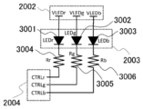
- FIG. 10 is a circuit diagram showing an example of a light source element 2003 in the image display unit 1001.
- 3 is a timing chart showing an example of a 1 ⁇ speed display operation of a video display unit 1001 in the video display device 10.
- 3 is a timing chart showing an example of a double speed display operation of the video display unit 1001 in the video display device 10.
- 4 is a timing chart illustrating an example in which a double-speed display operation and frame complementation are performed by a video display unit 1001 in the video display device 10.
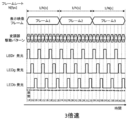
- 4 is a timing chart showing an example of a triple speed display operation of the video display unit 1001 in the video display device 10. It is a table
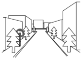
- 10 is a flowchart illustrating a determination processing flow by a control unit 1003 and an exercise determination processing unit 1006. It is an example of the outside world.
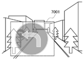
- 3 is a display example by the video display device 10.
- This is a video display example in which the contrast is weakened by the video processing unit 1008.
- This is an image display example in which the sharpness is weakened by the image processing unit 1008.
- 6 is an example of a video that is a target of the video determination processing unit 1009; It is another example of the image
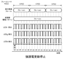
- 4 is a timing chart showing an example of a light source control stop display operation of a video display unit in the video display device 10.
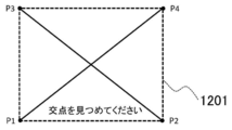
- FIG. 6 is a timing chart showing an example of an update stop operation example of a ferroelectric liquid crystal in a video display unit in the video display device 10; It is a figure which shows one Example of a 2nd sensor. It is detail drawing which shows one Example of a 2nd sensor. It is an example of a video at the time of initial setting of a video display device. It is a figure which shows the video display range at the time of the initial setting of a video display apparatus.
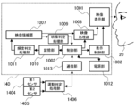
- FIG. 6 is a block diagram illustrating a video display device according to a second embodiment. It is a block diagram which shows the video display apparatus 140 by Example 2.
- FIG. It is a block diagram which shows the video display apparatus 150 by Example 2.
- FIG. It is a block diagram which shows the video display apparatus 160 by Example 3.
- FIG. FIG. 10 is a block diagram illustrating an example of a method for controlling a video display device according to a third embodiment.
- FIG. 1A is a block diagram showing an image display device that can be worn by a user and displays an image in front of the user's eyes.
- the video display device 10 includes a video display unit 1001, a display control unit 1002, a control unit 1003, a first sensor 1004, a second sensor 1005, a motion determination processing unit 1006, a video information source 1007, a video processing unit 1008, and a video determination processing unit. 1009, a storage unit 1010, a frequency determination processing unit 1011, and a power supply unit 1012.
- the video display apparatus 10 transmits the video information acquired from the video information source 1007 to the video display unit 1001 via the video processing unit 1008 to display the video.
- the video display unit 1001 is typically a display using a liquid crystal element or a mirror array element.
- the video information source 1007 appropriately selects video information data stored in a storage device (not shown), performs processing such as data decryption and decryption as necessary, and transmits the video information to 1008.
- a time-series moving image may be transmitted in time series, or a still image may be transmitted sequentially.
- the control unit 1003 is connected to a controller 1020 outside the video display device 10 by wire or wirelessly.
- the controller 1020 may be a controller dedicated to the video display device 10 or may be used as a controller by installing a dedicated application program on the smartphone.
- the power supply unit 1012 is provided with a switch for turning the power on / off separately from the controller.
- the display control unit 1002, the control unit 1003, the motion determination processing unit 1006, the video information source 1007, the video processing unit 1008, the video determination processing unit 1009, and the frequency determination processing unit 1011 are mounted on the video display device 10 as independent hardware. Is done. Alternatively, they may be realized by one or more arithmetic processors, microprocessors, software, and firmware. They may be implemented as a part of functional blocks of an integrated circuit, or may be realized by a programmable logic device such as an FPGA (Field-Programmable Gate Array).
- FPGA Field-Programmable Gate Array
- the storage unit 1010 does not need to be mounted as an individual component, and may be mounted as a partial functional block of the integrated circuit.
- FIG. 1B is an external view of an example of the video display device 10.
- Main components are housed in the joint between the lens and the vine, and an image is projected onto the lens portion that is a half mirror.
- the controller 1020 and the main body of the apparatus are connected by a cable.
- FIG. 1C is a diagram when the video display device 10 of FIG. 1B is mounted.
- FIG. 1D is an external view of another example of the video display device 10.
- Main components are housed in the joint between the lens and the vine, and the prism is a projection unit (2007 in FIG. 2) of the image display unit 1001.
- FIG. 1E is a diagram when the video display device 10 of FIG. 1D is mounted.
- FIG. 1F is an external view of still another example of the video display device 10.
- the prism in front of the eyes is a projection unit (2007 in FIG. 2) of the image display unit 1001, and other components are distributed and stored in the helmet and the vine portion.
- the video display unit 1001 includes a video signal processing unit 2001, a light source element power source control unit 2002, a light source element 2003, a light source driver 2004, a modulator 2005, a modulator driver 2006, a projection unit 2007, and a setting control unit 2008.
- the video information from the video processing unit 1008 is transmitted to the video signal processing unit 2001, and the video signal processing unit 2001 determines the brightness of the light source, the timing of driving the light source, and the modulator driving pattern corresponding to the received video information.
- the light source element power control unit 2002 controls the supply voltage to the light source element 2003 according to the received brightness information.
- the timing of driving the light source is transmitted to the light source driver 2004.
- the light source driver 2004 controls the light source element 2003 according to the timing of driving the light source.
- the light source element power control unit 2002 and the light source driver 2004 may be mounted in the same element.
- FIG. 3 shows a detailed configuration diagram of the light source element power source control unit 2002, the light source element 2003, and the light source driver 2004.
- the light source element 2003 includes three LEDs of three primary colors of a red LED 3001, a green LED 3002, and a blue LED 3003.
- the three LEDs are connected in series with current limiting resistors 3004, 3005, and 3006, respectively, and potentials VLEDr, VLEDg, and VLEDb are applied from the light source element power supply control unit 2002, respectively.
- the potentials of VLEDr, VLEDg, and VLEDb can be set to arbitrary values by the light source element power supply control unit 2002, and the light emission of the red LED 3001, the green LED 3002, and the blue LED 3003 can be controlled.
- the terminals of the current limiting resistors 3004, 3005, and 3006 on the opposite side of the LED are connected to the light source driver 2004.
- the light source driver 2004 changes the potential of each terminal of CTRLr, CTRLg, and CTRLb to control the light emission amount and the light emission time of the red LED 3001, the green LED 3002, and the blue LED 3003, respectively, and the modulator 2005 controls all the pixels (pixels). ) Is modulated.
- the display control unit 1002 sends a control signal designating the brightness of the light source to the setting control unit 2008 of the video display unit 1001.
- the light source has been described as having a configuration of three primary color LEDs one by one, it is not limited to this. It is good also as a structure which has one or more white LED. Moreover, light sources other than LED may be sufficient.
- the three primary colors may not be configured so that the light source emits only the primary color, and may be configured such that a specific color is extracted by a filter using, for example, a white light source and a dichroic filter or a color wheel.
- the modulator drive pattern is transmitted to the modulator driver 2006.
- the modulator driver 2006 drives the modulator 2005 according to the modulator driving pattern.
- the modulator 2005 is, for example, a transmissive liquid crystal element, LCOS (Liquid Crystal On Silicon), DMD (Digital Mirror Device), or the like.
- the modulator 2005 and the modulator driver 2006 may be configured as one element component.
- description will be made assuming that the modulator 2005 is an LCOS system.
- Light emitted from the light source element 2003 is modulated by the modulator 2005 and projected onto the projection unit 2007.
- the projection unit 2007 include a reflector such as a mirror, a scatterer such as a screen, a prism, a half mirror, and a lens. Also, a combination of these may be used.
- the video display device 10 of the present invention has a form like an opaque goggle that covers the entire field of view of the device user 20, and the device user 20 visually recognizes the outside world. It is possible to adopt a transmissive type in which an image is recognized by a part of the field of view. The following description assumes a transmissive type.
- the device user 20 visually recognizes an image as shown in FIGS. 7A, 7B, and 7C. That is, the device user 20 can recognize the external world as shown in FIG. 7A and the virtual video 7001 as shown in FIG.
- the video display device 10 has a mode in which video is projected on both eyes of the device user 20 and a mode in which only one eye is projected. In FIG. 2, it is assumed that only one eye is projected. However, when projecting to both eyes, two projection units 2007 are provided so that light from the modulator 2005 is incident on the left and right eyes. Configure as follows.
- the video display unit 1001 as a whole may have two configurations for the right eye and the left eye, and different images with parallax may be projected to form a stereoscopic video.
- the apparatus user 20 observes the light from the projection unit 2007, so that the light corresponding to the input video information can be recognized as a video.
- the setting control unit 2008 can receive the control signal and change the setting of the video signal processing unit 2001.
- the video display unit 1001 has two or more display methods for displaying video.
- the display method is illustrated in FIGS. 4A, 4B, 4C, and 4D.
- the video information is treated as moving image information in which N still images are arranged in a predetermined order per second on average, and N is a positive number of 1 or more.
- N is referred to as a frame rate, and is expressed as frames per second (fps: frames per second) as the number of still images per second.
- the frame rate is generally 30 fps or 60 fps, for example.
- the display count of the video display unit 1001 is changed with respect to the frame rate of the video information.
- FIG. 4A illustrates the first display method.
- the video display unit 1001 changes the display video once per 1 / N second with respect to the frame rate N.
- the display image is called a frame.
- a field sequential method (color time division method) will be described as an example. That is, for one frame display, the video display unit 1001 divides video information into primary color components of red, green, and blue, and displays video of each color component separately within a time obtained by further dividing 1 / N second into three. .
- the display of the modulator 2005 which is an LCOS, is set (1R) corresponding to the red component divided from the video information of frame 1, and the red LED 3001 is shorter than 1 / (3N) seconds. Light is emitted for a predetermined time (period 1R).
- the modulator 2005 is set to a setting (1G) corresponding to the green component of frame 1, and the green LED 3002 emits light for a predetermined time (period 1G) shorter than 1 / (3N) seconds.
- the modulator 2005 is set (1B) corresponding to the blue component of the frame 1, and the blue LED 3003 emits light for a predetermined time (period 1B) shorter than 1 / (3N) seconds.
- Such display of each color component is similarly performed on the frame 2 and the frame 3 of the display image.
- FIGS. 4A to 4D the description up to frame 3 is shown, but the same processing is repeated for the subsequent frames.
- FIG. 4B illustrates the second display method.
- the display time of each color component of the modulator 2005 for each frame is further divided into two, and 1 / N second corresponding to the frame rate N of the display image.
- One color component is displayed in a period divided into six.
- This second display method is called double speed drive because the modulator 2005 is driven at twice the update speed of the first display method.
- Changing the driving speed of the modulator 2005 and the light source element 2003 means changing the update period of the pixel information of the liquid crystal element or mirror array element.
- FIG. 4D shows a timing chart of the triple speed driving.
- FIG. 4C shows a modification at the time of double speed driving.
- the driving cycle of the modulator 2005 and the light source element 2003 is the same as the display method of FIG. 4B.
- the generation of the intermediate frame is performed by the video processing unit 1008.
- an intermediate frame can be generated even at an update rate such as 3 ⁇ speed or 4 ⁇ speed faster than 2 ⁇ speed, and is not limited to 2 ⁇ speed.
- the device user 20 When the 1 ⁇ speed display, 2 ⁇ speed display, 3 ⁇ speed display, and double speed are given, or by generating an intermediate frame, the device user 20 is less likely to perceive color breakup, and the motion of the image is reduced. Will be smooth, but power consumption will increase.
- the display control unit 1002 transmits a control signal instructing switching of the display method via the setting control unit 2008 of the video display unit 1001.
- the video processing unit 1008 can change the video information input from the video information source 1007 and output it to the video display unit 1001.
- the video information is, for example, information including data of H ⁇ V pixels vertically (H is an integer of 1 or more) and V (V is an integer of 1 or more) horizontally.
- Changing the contrast of an image is a process for changing the difference between light and dark colors.
- a pixel value input from the video information source 1007 is multiplied by a proportional coefficient higher than 1 to be a pixel value to be output to the video display unit 1001. It is processing.
- the image brightness change is a process of incrementing a pixel value by a specified value to obtain an output pixel value.
- An arbitrary value is added to the pixel value input from the video information source 1007 to display a video. This is processing for converting the pixel value to be output to the display unit 1001.
- the video processing unit 1008 performs processing such as increasing or decreasing the contrast of the image and / or increasing or decreasing the brightness of the image in accordance with a signal from the control unit 1003.
- the video processing unit 1008 may change other parameters related to the image, for example, sharpness, saturation, and hue in accordance with a signal from the control unit.
- the video processing unit 1008 can be switched to send video information to the video display unit 1001 without performing these processes in accordance with a signal from the control unit 1003.
- the first sensor 1004 is a sensor for detecting the rotation of the head of the device user 20, for example, a gyro sensor.
- the first sensor 1004 outputs a three-dimensional motion vector indicating the head movement for a predetermined time.
- the second sensor 1005 is a line-of-sight sensor for detecting the movement of the line of sight and the position of the gazing point, and outputs a two-dimensional motion vector or a three-dimensional vector indicating the line-of-sight movement of the device user 20 for a predetermined time.
- the exercise determination processing unit 1006 determines the exercise status of the device user 20 from the outputs of the first sensor 1004 and the second sensor 1005. Specifically, there are three directions: head movement, line-of-sight movement, head movement, and line-of-sight movement direction. Processing for determining these three items from the sensor output will be described later.
- the motion determination processing unit 1006 determines whether or not the gazing point is on the virtual video 7001 by the video display device, and the processing will be described later.
- the control unit 1003 determines the processing contents from the determination result of the motion determination processing unit 1006 according to FIG. 5, the display speed of the video display unit 1001 is displayed on the display control unit 1002, and the processing related to the video parameters is performed on the video processing.
- the unit 1008 is instructed.
- the process A is a process in which the display method of the video display unit 1001 is set to 1 ⁇ speed driving, the video processing by the video processing unit 1008 is not performed, and the video from the video information source is passed to the video display unit 1001 without any change. .
- This is the process with the least power consumption.
- Pattern 5 is different from Pattern 1 in that the point of gaze detected by the second sensor 1005 is not on the virtual image. At this time, the apparatus user 20 is stopped, and the virtual image 7001 is not visually recognized, and the importance of visibility is reduced, so the control unit 1003 instructs the process B.
- Processing B is processing in which the display method of the video display unit 1001 is set to 1 ⁇ speed driving and the video processing unit 1008 reduces the contrast and brightness of the video by a predetermined amount.
- Pattern 3, pattern 5, and pattern 8 in FIG. 5 are either when the movement of the head of the apparatus user 20 is detected or the movement of the line of sight is detected, and are on the gazing point virtual image It is. In these patterns, the device user 20 is not stationary, and the possibility that the device user 20 of the video display device 10 feels uncomfortable increases, so the need for consideration for discomfort increases.
- the control unit 1003 for reducing discomfort instructs the processing C.
- the display method of the video display unit 1001 is set to the triple speed with a higher update speed, while the video processing by the video processing unit 1008 is returned to the initial value.
- Pattern 4, pattern 6, and pattern 9 in FIG. 5 are either when the movement of the head of the apparatus user 20 is detected or the movement of the line of sight is detected, and the gazing point is not on the virtual video. It is. In these patterns, the device user 20 is not stationary, and the necessity of considering the discomfort of the device user 20 is increased. However, the device user 20 does not visually recognize the virtual image 6001 and is visually recognized. Therefore, the control unit 1003 instructs the process D.
- the display method of the video display unit 1001 is set to triple speed with a faster update speed, while the video processing unit 1008 reduces the contrast and brightness of the video by a predetermined amount.
- the movement of the head of the apparatus user 20 is detected and the movement of the line of sight is detected. If the direction of movement of the head at this time and the direction of movement of the line of sight are substantially the same direction, the eye movement is highly likely to be a so-called saccade (intermittent movement), and the device user 20 There is a high possibility that both the outside world and the virtual video 7001 are not recognized. In such a case as well, it is necessary to consider the discomfort of the device user 20 in the video, but since the importance of the visibility of the virtual video is low, the control unit 1003 instructs the process D described above.
- FIG. 6 is a flowchart for realizing the control mode by the pattern shown in FIG. 5, and is executed by the control unit 1003 and the motion determination processing unit 1006.
- the process starts from step S010.
- step S020 the control unit 1003 performs initial setting and energization processing of the first sensor 1004 and the second sensor 1005.
- the display method of the video display unit 1001 is set to double speed, and various parameters of the video processing unit 1008 are set to specified initial values.
- step S030 the motion determination processing unit 1006 acquires a sensor output from the first sensor 1004.
- step S040 the motion determination processing unit 1006 acquires a sensor output from the second sensor 1005.
- step S050 the motion determination processing unit 1006 determines from the output of the first sensor whether the magnitude of the rotational speed of the head is equal to or greater than the specified value A1 (A1 is a positive value), and the determination result is X. . X is true ('1') if the detection result is greater than or equal to the specified value A1, and X is false ('0') if it is less than A1.
- step S060 the motion determination processing unit 1006 determines from the output of the second sensor whether the magnitude of the movement speed of the line of sight is equal to or greater than a specified value S1 (S1 is a positive value). And If the detection result is greater than or equal to the specified value S1, Y is true ('1'), and if it is less than S1, Y is false ('0').
- step S070 the motion determination processing unit 1006 determines whether the two-dimensional coordinates of the line-of-sight position (gaze point) are on the virtual image (within a predetermined range) from the output of the second sensor, and the determination result Is Z.
- Z is true ('1')
- Z is false ('0').
- XOR exclusive OR
- step S100 the motion determination processing unit 1006 compares the head moving speed direction output from the first sensor 1004 with the line-of-sight moving direction output from the second sensor 1005, and the motion vector direction is determined. It is determined whether or not they substantially match. The determination method will be described later.
- step S111 conditional branching is performed based on the determination result Z. If Z is true, the process proceeds to step S140, and the control unit 1003 instructs process C. If Z is false, the process proceeds to step S150, and the control unit 1003 instructs process D.
- step S160 it is determined whether this flow is set to be continuously executed.
- the apparatus user 20 may set or change the setting, or a default may be set. If the setting is valid, the process proceeds to standby step S170, and if the setting is invalid, the process proceeds to end step S180.
- step S170 after waiting for a predetermined time (about 300 milliseconds to 10 seconds), the process returns to step S030.
- step S180 power-off processing and suspension setting for the first sensor 1004 and the second sensor 1005 are performed. The process ends in end step S190.
- the video display device 10 has a storage unit 1010.
- the control unit 1003 records the changed history, time, and the like in the storage unit 1010.
- the frequency determination processing unit 1011 is a video information source 1007. Is requested to change the setting of the video information according to the change history.
- the video information change request is performed, for example, at the timing of the end process in step S180 in FIG. 6, and the video information change is a change in parameters such as image contrast, sharpness, saturation, hue, and image brightness. .
- Gaze Sensor An example of a gaze sensor that is the second sensor 1005 will be introduced. As shown in FIG. 11A, a sensor A element 1101, a sensor B element 1102, and a detection controller 1103 are provided. When the sensor A element 1101 detects movement, the detection controller 1103 activates the sensor 2 element 1102 and instructs the sensor B element to output more precise data.
- FIG. 11B A more specific configuration is shown in FIG. 11B. It is suitable for mounting on a frame portion of a glasses-type device as shown in FIGS. 1B and 1D.
- the line-of-sight sensor can detect the movement of the eye 1111 of the device user 20, and includes a first light projecting unit 1112 and a second light projecting unit 1113 that emit infrared light, a first light receiver 1114, and a second light receiving unit.
- the infrared light emitted from the first light projecting unit 1112 and the second light projecting unit 1113 is projected onto the eye 1111 of the device user 20 and reflected.
- the reflected infrared light is incident on the first light receiver 1114 and the second light receiver 1115.
- the first light receiver 1114 and the second light receiver 1115 are installed in different directions with respect to the eye 1111, and the amount of received light varies depending on the position of the black eye and the white eye. Since the first light receiver 1114 and the second light receiver 1115 are arranged on the left and right of the eye 1111, the change in the amount of received light when the eye 1111 is displaced differs depending on the light receiver.
- the movement of the eye 1111 can be detected by obtaining a difference by the comparator 1116 from the amount of light received by the first light receiver 1114 and the amount of light received by the second light receiver 1115. This is a detection method called scleral reflection method.
- the motion detector 1120 determines that the movement of the eye 1111 is detected when the output of the comparator 1116 is equal to or greater than a predetermined value, outputs a motion detection signal, and moves to the eye 1111 when the output of the comparator 1116 is smaller than the predetermined value. It is determined that there is no motion, and a motion non-detection signal is output.
- the pause control unit 1121 places the first camera 1117 and the second camera 1118 in an imaging state capable of capturing an image, and these cameras are reflected from the eyes 1111.
- the eye 1111 is imaged with infrared light.
- Image processing is performed by an image processing unit (not shown) from videos captured by the first camera 1117 and the second camera 1118, and more detailed movement of the line of sight and the position of the viewpoint are estimated.
- a dark pupil method, a corneal reflection method, or the like is used.
- the pause control unit 1121 stops a part of functions in the first camera and the second camera and puts them into a pause state that suppresses power consumption.
- the motion detection processing unit 1120 changes the power supplied to the first light projecting unit 1112 and the second light projecting unit 1113 by sending a motion detection or motion non-detection signal to the current control unit 1119. Control is performed so that the amount of current in the imaging state is greater than the amount of current in the resting state.
- a camera element has higher power consumption than a photoreceiver, and more light is required for detection. For this reason, the power consumption of the apparatus is suppressed by this control method in which the camera element is in the imaging state only when a rough movement is detected by the light receiver, rather than the camera element is always in the imaging state.
- the case where there are two light projecting units is illustrated, but the number is not limited to this. Furthermore, you may have many light projection parts. Further, the light receiving timing of each light projecting unit may be controlled to be different, and the light receiver or the camera element may acquire data in accordance with the light emission of each light projecting unit.
- the number of camera elements and light receivers is exemplified as two, but the number is not limited to this.
- the light receiver and the camera element may be configured as one element.
- some pixels of the camera element may be configured as a light receiver.
- Initialization processing of the second sensor 1005 may be performed in the initial setting step S020 shown in FIG.
- the second sensor 1005 is a sensor that detects the line of sight of the device user 20
- the motion determination processing unit 1006 displays a diagonal virtual image 1201 in the display area as shown in FIG. 12A on the video display unit 1001 during the initialization process, and looks at the intersection of the device user 20. Display a text prompting you to do so.
- the second sensor 1005 detects that the position of the gazing point is stationary for a predetermined number of seconds, it is determined that the device user 20 is staring at the intersection of the virtual images 1201, and the position of the gazing point is determined.
- the reference position p0 (h0, v0) of the two sensors 1005 is set.
- the detection timing of the reference position may be performed at the time designated by the apparatus user 20 by the controller 1020 in addition to the initial processing.
- the device user 20 may instruct the second sensor 1005 to detect the detection timing by intentionally blinking a specific length or a specific order before and after gaze at a specified point.
- the virtual display image 1202 does not have to be a square, and may be another figure such as a triangle or a circle.
- Direction of Eye Movement of Head Movement In the movement determination unit 1006, the direction of movement of each of the head movement and the eye movement is calculated from the motion vector output of the first sensor 1004 and the motion vector output of the second sensor 1005. Detect if matches.
- the output of the first sensor 1004 and can be expressed by three-dimensional vector A 0.
- the orthogonal projection vector of the three-dimensional vector A 0 with respect to the plane S is A.
- a similar vector conversion process is performed when the output of the second sensor 1005 is a three-dimensional vector.
- the distance that the device user 20 recognizes the virtual image 7001 is determined by the optical configuration of the projection unit 2007 and the like in the image display unit 1001, and the device user 20 moves the virtual image 7001 away by a predetermined distance by the focus adjustment function of the eyeball. Recognize at the position.
- the second sensor 1005 When the second sensor 1005 outputs a two-dimensional vector B0, consider the plane T of the three-dimensional space including the detecting axis of the second sensor 1005, converts the two-dimensional vector B0 to a three-dimensional vector B 1 on the plane T and, the orthogonal projection vector relative to the plane S of the three-dimensional vector B 1 and B.
- a similar vector conversion process may be performed when the detection result of the first sensor 1004 is obtained as a two-dimensional output.
- the movement vector of the output of the first sensor 1004 is A
- the movement vector B of the output of the second sensor 1005 is an angle formed by both vectors.
- (ANGLE) ⁇ A comparison is made by comparing the absolute value of ANGLE (AB) with an arbitrary value ⁇ ( ⁇ is a positive value).
- the first sensor 1004 and the second sensor 1005 are an acceleration sensor, a geomagnetic sensor, a GPS, a camera that shoots a user, a camera that shoots an external image viewed from the user, and measures the pulse of the user.
- a sensor, a sensor for measuring the blood flow of the user, a clock, or the like may be used.
- the first sensor 1004 and the second sensor 1005 may each include a filter, an amplifier, a level shifter, and the like.
- a configuration including a comparator and transmitting a binary result indicating whether the detection result is higher or lower than the threshold value together with the vector value may be used.
- a signal may be output indicating that motion has been detected.
- the video determination processing unit 1009 may determine the feature of the image.
- the video determination processing unit 1009 determines whether or not the video information may cause display discomfort to the device user 20. For example, as shown in FIG. 9A, in the case of an image in which an object moves continuously in the screen, the apparatus user 20 is predicted to follow the moving image by moving the eyeball. Further, for example, as shown in FIG. 9B, when the video includes content that makes sense by continuously recognizing a character string or the like in the vertical, horizontal, and diagonal directions, the user 20 It is expected to move the viewpoint along the image by moving.
- Such an image can be detected in advance by the video determination processing unit 1009 analyzing the digital image and referring to the amount of difference data between image frames. 9A and 9B, the video determination processing unit 1009 outputs a control signal to the control unit 1003 so that the process C is applied in the case of a video whose movement of the viewpoint is predicted in advance.
- the video determination processing unit 1009 determines whether the video to be displayed is a video related to the outside world, for example, an augmented reality (AR) video. You may judge.
- the video determination processing unit 1009 can determine the type of video from video metadata and additional information.
- the virtual video 7001 in FIG. 7B displays information related to the external world in FIG. 7A, and when it is determined that the video is related to the external world in this way, the point of interest is a position other than the virtual video 7001. Even if it is detected (Z is false), since the importance of the visibility of the display image is high, the controller 1003 is instructed to apply the process C in FIG.
- the display method shown in FIG. 10A may be adopted.
- the double speed driving shown in FIG. 4B is performed, the control of the light source is stopped, and the light emission periods of the red LED 3001, green LED 3002, and blue LED 3003 of the light source element 2003 are made substantially simultaneous.
- the light from the three LEDs is mixed, and the device user 20 recognizes the video as a black and white image, and in principle, no color break occurs.
- the present invention may be applied to the processes C and D in FIG.
- the frame update of the modulator 2005 may be stopped. For example, as shown in FIG. 10B, when the frames 1, 2, and 3 are substantially the same image, the modulator 2005 continues to display the same frame 1 during the period corresponding to these frames.
- the video information can be expressed as H ⁇ V pixel information (both H and V are positive integers)
- the number of pixels whose information has been changed between consecutive frames is that the images are substantially the same.
- H ⁇ V the number of pixels whose information has been changed between consecutive frames
- the color information of each pixel can be expressed as primary color information of R, G, B (for example, R, G, B are positive integers from 0 to 255)
- continuous frames The change in the R, G, and B values of each pixel is sufficiently small.
- the modulator 2005 uses a ferroelectric liquid crystal, power is consumed for erasing and redisplaying information in order to display the same frame a plurality of times. Stopping the frame update of the modulator 2005 further reduces power consumption. You may apply to the process C and the process D of FIG.
- the video information source 1007 may be configured to acquire video information from the outside.
- it may be a receiver that complies with video transmission standards such as DVI, HDMI (registered trademark), and DisplayPort, or a receiver that uses a general electric signal transmission method such as SPI, I2C, RS232, or USB.
- It may be a wired network receiver such as Ethernet (registered trademark) or a wireless network receiver such as a wireless LAN or Bluetooth (registered trademark).
- the video information source 1007 may include a decoder that receives compressed information and expands it to video information, and includes a function that receives and decrypts encrypted video information. Also good.
- the power supply unit 1012 supplies power to the video display device 10.
- the power supply unit 1012 is a rechargeable battery that can be charged from an external power source as a power source, a power supply circuit that extracts desired power from a replaceable primary battery, a converter that connects to an external power source such as an outlet, and power Includes one or more of the stabilizing circuits.
- the power supply unit 1012 may include a power control integrated circuit for controlling charging, supply power, etc. or observing the power source.
- the control unit 1003 acquires information on the remaining power amount of the power source from the power supply unit 1012, and controls the video processing unit 1008 to operate the video processing only when the remaining power amount exceeds a predetermined value.
- the control unit 1003 may be configured to change the display method of the video display unit 1001 so that the display cycle is shortened only when the remaining power amount of the power supply unit 1012 exceeds a predetermined value.
- the control unit 1003 may be configured to change the display method of the video display unit 1001 so that the display cycle becomes longer when the remaining power amount of the power supply unit 1012 is lower than a predetermined value.
- FIG. 13 is an explanatory diagram of the second embodiment. Only the parts different from FIG. 1 will be described.
- the first sensor 1304 and the second sensor 1305 are provided separately from the housing of the video display device 130. Each sensor detects the operation of the device user 20 as in the first embodiment.
- exchange of information between the first sensor 1304 and the video display device 130 is performed via the communication unit 1013.
- the communication unit 1013 and the first sensor 1304 may communicate with each other as an electrical signal on a physically connected conductor, or via wireless communication such as a wireless LAN, Bluetooth (registered trademark), or Zigbee (registered trademark). It may be done.
- the first sensor 1304 may be configured to include a communication unit (not shown). When using wireless communication, the first sensor 1304 may be supplied with power from a power source different from that of the video display device 130.
- the second sensor 1305 may exchange information with the communication unit 1013 using the wired communication or the wireless communication.
- the second sensor 1305 may be configured to include a communication unit (not shown). Further, when wireless communication is used, power may be supplied from a power source different from that of the video display device 130.
- the motion determination processing unit 1006 receives the outputs of the first sensor 1304 and the second sensor 1305 via the communication unit 1013.
- the first sensor 1404, the second sensor 1405, and the motion determination processing unit 1406 are provided separately from the housing of the video display device 140. Information exchange between the motion determination processing unit 1406 and the control unit 1003 is performed via the communication unit 1013, and may be performed by the wired communication or the wireless communication.
- the first sensor 1404, the second sensor 1405, and the motion determination processing unit 1406 may be included in the same housing. Further, the motion determination processing unit 1406 may be configured to include a communication unit (not shown).
- the second sensor 1305 is provided separately from the casing of the video display device 150.
- Information exchange between the second sensor 1305 and the motion determination processing unit 1006 is performed via the communication unit 1013, and may be performed by wired communication or wireless communication as described above.
- the first sensor 1304 and the second sensor 1305 provided separately do not need to be attached to the device user 20, and may only detect the movement of the head of the device user 20, the movement of the eyes, etc.
- a sensor using image processing may be used. It is assumed that the apparatus user 20 works while watching the image at a fixed position, and the camera-type first sensor 1304 and the second sensor 1305 are installed on the work table. Further, when the device user 20 stands upright or sits at a fixed position and uses the image display device 130, the image display device 140, or the image display device 150, the pressure distribution for measuring the displacement of the center of gravity position below the device user 20.
- a first sensor 1304 or a second sensor 1305 may be provided by providing a detection sensor such as a measuring instrument.
- FIG. 16 is an explanatory diagram of the third embodiment. Only the parts different from FIG. 1 will be described.
- the storage unit 1610 and the frequency determination processing unit 1611 are provided in the server 1601 separately from the video display device 160.
- the operations of the storage unit 1610 and the frequency determination processing unit 1611 are the same as those of the storage unit 1010 and the frequency determination processing unit 1011 of the first embodiment.
- Information exchange between the storage unit 1310 and the control unit 1003 is performed via the communication unit 1013 of the video display device 160 and the communication unit 1612 of the server 1601, and the communication unit 1013 and the communication unit 1612 are physically connected. It may be communicated as an electrical signal on a conductive wire connected to, or may be performed via wireless communication such as wireless LAN, Bluetooth (registered trademark), Zigbee (registered trademark). Similarly, information exchange between the frequency determination processing unit 1611 and the video information source 1007 is performed via the communication unit 1013 and the communication unit 1612, and may be performed by wired communication or wireless communication as described above. .
- FIG. 17 shows a control method in a system including a plurality of video display devices 160.
- the first video display device 1711, the second video display device 1712, the third video display device 1713, and the fourth video display device 1714 can communicate with the server 1601 via the network 1730.
- the first video display device 1711 is used by the first user 1721
- the second video display device 1712 is used by the second user 1722
- the third video display device 1713 is used by the third user 1723
- the fourth video display device 1714 is used by the fourth user 1724.
- the server 1601 includes a storage unit 1610 and a frequency determination processing unit 1611, and includes a first video display device 1711, a second video display device 1712, a third video display device 1713, and a fourth video display device 1714.
- a history or time when the display method of the video display unit 1001 is changed or the processing method of the video processing unit 1008 is changed is received from the control unit 1003 via the network 1730.
- the server 1601 extracts common information from the change information sent from each video display device, and the processing of each video display device recorded in the storage unit 1610 by the frequency determination processing unit 1611 is common.
- the common processing exceeds a predetermined number of times within a predetermined time, the video information source 1007 is requested to change the video information.
- the change of the video information is, for example, a change of parameters such as image contrast, sharpness, saturation, hue, and image brightness.
- the number of video display devices 160 connected to the network 1730 is not limited to the number shown in the present embodiment, and one or more video display devices 160 may be connected.
- DESCRIPTION OF SYMBOLS 10 ... Video display apparatus 1001 ... Video display part 1002 ... Display control part 1003 ... Control part 1004 ... 1st sensor 1005 ... 2nd sensor 1006 ... Motion determination process part 1007 ... Video information source 1008 ... Video processing unit 1009 ... Video judgment processing unit 1010 ... Storage unit 1011 ... Frequency judgment processing unit 1012 ... Power supply unit 1013 ... Communication unit 1020 ... Controller 20: Device user 2001 ... Video signal processing unit 2002 ... Light source element power source control unit 2003 ... Light source element 2004 ... Light source driver 2005 ... Modulator 2006 ... Modulator Driver 2007 ... Projection unit 2008 ... Setting control unit 3001 ... Red LED 3002 ... Green LED 3003 ...
- Frequency determination processing unit 1612 Communication unit 1711 ... First video display device 1712 ... Second video display device 713 ... Third video display device 1714 ... Fourth video display device 1721 ... First user 1722 ... Second user 1723 ... Third user 1724 ... ⁇ Fourth user 1730 ... Network
Landscapes
- Engineering & Computer Science (AREA)
- Physics & Mathematics (AREA)
- General Physics & Mathematics (AREA)
- Theoretical Computer Science (AREA)
- Multimedia (AREA)
- Signal Processing (AREA)
- Computer Hardware Design (AREA)
- Optics & Photonics (AREA)
- Human Computer Interaction (AREA)
- General Engineering & Computer Science (AREA)
- Control Of Indicators Other Than Cathode Ray Tubes (AREA)
- Controls And Circuits For Display Device (AREA)
- Liquid Crystal Display Device Control (AREA)
Abstract
Description
1.装置の概要
図1Aは使用者に装着可能で、使用者の眼前に映像が表示される映像表示装置を示すブロック図である。
映像表示部1001の構成例を図2に図示する。映像表示部1001は、映像信号処理部2001、光源素子電源制御部2002、光源素子2003、光源ドライバ2004、変調器2005、変調器ドライバ2006、投影部2007、設定制御部2008を備えている。
光源駆動のタイミングは光源ドライバ2004に送信される。光源ドライバ2004は 光源駆動のタイミングに応じて、光源素子2003を制御する。
光源素子電源制御部2002と光源ドライバ2004は同一の素子内に実装されていてもよい。
変調器駆動パターンは変調器ドライバ2006に送信される。変調器ドライバ2006は前記変調器駆動パターンに応じて変調器2005を駆動する。
変調器2005は例えば透過型液晶素子やLCOS(Liquid Crystal On Silicon)、DMD(Digital Mirror Device)などである。
変調器2005と変調器ドライバ2006は一つの素子部品として構成されてもよい。
以下変調器2005をLCOS方式と想定して説明する。
投影部2007は例えばミラーなどの反射物やスクリーンなどの散乱物、またはプリズム、ハーフミラー、レンズなどが挙げられる。また、これら複数の組み合わせでもよい。
設定制御部2008は制御信号を受信し、映像信号処理部2001の設定を変更することができる。
例えば図4Dのように2倍速よりも速い3倍速や4倍速などの更新速度であっても、中間フレームの生成は可能であり、2倍速に限るものではない。
映像情報は例えば1フレームにつき縦にH個(Hは1以上の整数)横にV個(Vは1以上の整数)のH×V個の画素のデータを含む情報である。
画像のコントラスト変更とは、色の明暗の差異を変化させる処理で、映像情報源1007から入力された画素値に1より高い比例係数を掛けた値を映像表示部1001に出力する画素値とする処理である。
映像処理部1008は、制御部1003からの信号に応じて画像のコントラストを上げるまたは下げる、および/または画像の明るさを上げるまたは下げるなどの処理をおこなう。
映像処理部1008は、制御部1003からの信号に応じて、これらの処理を行わずに映像情報を映像表示部1001に送るように切り替えることも可能である。
第1センサ1004は装置利用者20の頭部の回転を検出するためのセンサであり、例えばジャイロセンサである。第1センサ1004は、所定時間の頭部の動きを示す3次元動きベクトルを出力する。第2センサ1005は視線の動きや注視点の位置を検出するための視線センサであり、装置利用者20の所定時間の視線の動きを示す2次元動きベクトルまたは3次元ベクトルを出力する。
制御部1003は、前記運動判定処理部1006の判定結果から、処理内容を図5にしたがって決定して、映像表示部1001の表示速度を表示制御部1002に、および映像のパラメータに関する処理を映像処理部1008に指示する。
これらのパターンでは、装置利用者20は静止しておらず、映像表示装置10の装置利用者20が不快を感じる可能性が増すため、不快感への配慮の必要性は高くなる。不快感を低減するための制御部1003は処理Cを指示する。
これらのパターンでは、装置利用者20は静止しておらず、装置利用者20の不快感への配慮の必要性は高くなるが、装置利用者20は仮想映像6001を視認しておらず、視認性の重要度も低いため、制御部1003は処理Dを指示する。
本体電源スイッチがONにされた時、あるいは、装置利用者20からの指示があった時に、ステップS010から処理が開始される。
ステップS040において、運動判定処理部1006が第2センサ1005からセンサ出力を取得する。
ステップS060では、運動判定処理部1006が、第2センサの出力から、視線の移動の速度の大きさが、規定値S1(S1は正の値)以上であるかを判定し、判定結果をYとする。該検出結果が規定値S1以上であればYは真(‘1’)とし、S1未満であればYは偽(‘0’)とする。
ステップS080では、運動判定処理部1006が、前記判定結果Xと前記判定結果Yの論理積に基づいて条件分岐をおこなう。X・Y=0であるならば、ステップS110に進み、X・Y=1であるならばステップS090に進む。
ステップS110では、Zが真であるならばステップS120に進み、制御部1003が処理Aを指示し、Zが偽であるならばステップS130に進み、制御部1003が処理Bを指示する。
ステップS111では、判定結果Zに基づいて条件分岐を行う。Zが真であるならばステップS140に進み、制御部1003が処理Cを指示し、Zが偽であるならばステップS150に進み、制御部1003が処理Dを指示する。
ステップS180では第1センサ1004および第2センサ1005の電源遮断処理や休止設定を実施する。
終了ステップS190で処理が終了する。
第2センサ1005である視線センサの1例を紹介する。
図11Aに示すようにセンサA素子1101とセンサB素子1102と検出制御器1103を備える構成である。センサA素子1101が動きを検出すると検出制御器1103がセンサ2素子1102を起動し、より精密なデータを出力するようにセンサB素子に命令する。
動き検出処理部1120は、動き検出あるいは動き不検出の信号を電流制御部1119に送る事によって、第一の投光部1112および第二の投光部1113への供給電力を変更する。休止状態における電流量よりも撮像状態における電流量が大きくなるように制御する。
本実施例では投光部は二つの場合を例示したが、個数はこれに限るものではない。さらに多くの投光部を有してもよい。また、各投光部の発光タイミングを異なるように制御して、各投光部の発光に合わせて受光器またはカメラ素子はデータを取得する構成でもよい。
図6に示した初期設定ステップS020では、第2センサ1005の初期化処理を行ってもよい。第2センサ1005が装置利用者20の視線を検出するセンサである場合、装置利用者20の注視点と第2センサと位置の間に、装置の使用毎にずれが生じる可能性がある。
仮想表示映像1202は四角形である必要はなく、三角形や円形などその他の図形でもよい。
運動判定部1006では、第1センサ1004の動きベクトル出力と、第2センサ1005の動きベクトル出力から、頭部の動きと視線の動きのそれぞれの動きの方向が一致するかを検出する。
装置利用者20が仮想映像7001を認識する距離は映像表示部1001内の投影部2007などの光学的な構成によって決まり、装置利用者20は眼球の焦点調節機能により仮想映像7001を所定の距離離れた位置に認識する。
(1)第1センサ1004と第2センサ1005は、加速度センサ、地磁気センサ、GPS、使用者を撮影するカメラ、使用者から見た外界映像を撮影するカメラ、使用者の脈拍を測定するセンサ、使用者の血流を測定するセンサ、時計などでもよい。また、第1センサ1004および第2センサ1005はそれぞれにフィルタや増幅器やレベルシフタなどを含んでいてもよい。または、コンパレータを含んで、閾値に対して検出結果が高いか低いかの二値での結果をベクトル値とともに送信する構成でもよい。また、検出結果である動きの持続時間が所定の時間を超えた場合、動きが所定の速度を超えた場合、動きが所定の変動量を超えた場合のいずれかの一つ以上の条件を満たすときに、動きが検出されたとする信号を出力する構成でもよい。
映像判定処理部1009は、映像情報が装置利用者20に対して、表示の不快感を発生する可能性があるかを判定する。例えば図9Aに示すように画面内を物体が連続的に移動するような映像の場合、装置使用者20は移動する映像に対して眼球を動かして追従すると予測される。また、例えば図9Bに示すように画面内に文字列などの縦、横、斜めの方向に連続的に認識することで意味を生じるような内容が映像に含まれる場合、装置使用者20は眼球を動かして視点を映像に沿って動かすことが予想される。
図9A、図9Bのようにあらかじめ視点を動かすことが予測されるような映像の場合は、処理Cを適用するように、映像判定処理部1009が制御部1003に制御信号を出力する。
また、映像情報源1007は、圧縮された情報を受信して伸張することで映像情報にするデコーダを含んでいてもよいし、暗号化された映像情報を受信して復号する機能を含んでいてもよい。
制御部1003は、電源部1012の残り電力量が所定値を上回る場合のみ、映像表示部1001の表示方法を表示周期が短くなるように変更できる構成としてもよい。
制御部1003は、電源部1012の残り電力量が所定値を下回る場合、映像表示部1001の表示方法を表示周期が長くなるように変更する構成としてもよい。
第1センサ1304、第2センサ1305は映像表示装置130の筐体とは分離して設けられている。いずれのセンサも実施例1と同様、装置使用者20の動作を検出する。
運動判定処理部1006は通信部1013を介して、第1センサ1304ないし第2センサ1305の出力を受信する。
図14に示す変形例では、第1センサ1404、第2センサ1405、運動判定処理部1406は、映像表示装置140の筐体とは分離して設けられている。運動判定処理部1406と制御部1003との間の情報のやり取りは通信部1013を介して行われ、前記の有線通信で行っても前記の無線通信で行ってもよい。また、第1センサ1404、第2センサ1405、運動判定処理部1406が、同一の筐体内に含まれる構成でもよい。また、運動判定処理部1406は図示しない通信部を含んで構成されてもよい。
また、装置使用者20が定位置に直立または着座して映像表示装置130、映像表示装置140、映像表示装置150を使用する場合、装置利用者20の下に重心位置の変位を測定する圧力分布測定器などの検出センサを設けることで、第1センサ1304または第2センサ1305としてもよい。
本実施例では、記憶部1610、頻度判定処理部1611は映像表示装置160と分離してサーバー1601に設けられる。記憶部1610、頻度判定処理部1611の動作は実施例1の記憶部1010、頻度判定処理部1011とそれぞれ同様である。
頻度判定処理部1611と映像情報源1007との間の情報のやり取りも同様に通信部1013と通信部1612を介して行われ、前述の様に有線通信で行っても無線通信で行ってもよい。
サーバー1601は記憶部1610と頻度判定処理部1611を有しており、第一の映像表示装置1711、第二の映像表示装置1712、第三の映像表示装置1713、第四の映像表示装置1714の制御部1003から、ネットワーク1730を介して、映像表示部1001の表示方法を変更した際、または映像処理部1008の処理方式を変更した際の履歴や時刻などを受信する。
1001・・・映像表示部
1002・・・表示制御部
1003・・・制御部
1004・・・第1センサ
1005・・・第2センサ
1006・・・運動判定処理部
1007・・・映像情報源
1008・・・映像処理部
1009・・・映像判定処理部
1010・・・記憶部
1011・・・頻度判定処理部
1012・・・電源部
1013・・・通信部
1020・・・コントローラ
20・・・装置利用者
2001・・・映像信号処理部
2002・・・光源素子電源制御部
2003・・・光源素子
2004・・・光源ドライバ
2005・・・変調器
2006・・・変調器ドライバ
2007・・・投影部
2008・・・設定制御部
3001・・・赤色LED
3002・・・緑色LED
3003・・・青色LED
3004、3005、3006・・・電流制限抵抗
7001・・・仮想映像
1101・・・センサA
1102・・・センサB
1103・・・検出制御部
1111・・・目
1112、1113・・・投光部
1114、1115・・・受光器
1116・・・比較器
1117、1118・・・カメラ
1119・・・電流制御部
1120・・・動き検出処理部
1121・・・休止制御部
1201・・・仮想映像
1202・・・仮想表示映像
130・・・映像表示装置
1304・・・第1センサ
1305・・・第2センサ
140・・・映像表示装置
1404・・・第1センサ
1405・・・第2センサ
1406・・・運動判定処理部
150・・・映像表示装置
160・・・映像表示装置
1601・・・サーバー
1610・・・記憶部
1611・・・頻度判定処理部
1612・・・通信部
1711・・・第一の映像表示装置
1712・・・第二の映像表示装置
1713・・・第三の映像表示装置
1714・・・第四の映像表示装置
1721・・・第一の使用者
1722・・・第二の使用者
1723・・・第三の使用者
1724・・・第四の使用者
1730・・・ネットワーク
Claims (15)
- 利用者の頭部に装着可能な映像表示装置であって、
二つ以上の表示方法を切り替えることができる映像表示部と、
前記映像表示部に表示方法を指定する制御部と、
利用者の頭部の動きを検出する第一の検出部と、
利用者の視点の動きを検出する第二の検出部と、
前記第一の検出部の出力と前記第二の検出部の出力により装置利用者の運動状況を判定する運動判定部と、
を含み、
前記制御部は前記運動判定部の判定結果に応じて、前記映像表示部に前記表示方法の変更を指示することを特徴とする映像表示装置。 - 請求項1に記載の映像表示装置であって、
前記映像表示部は液晶素子またはミラーアレイ素子を用いたディスプレイであって、
前記二つ以上の表示方法とは、液晶素子またはミラーアレイ素子の画素情報の更新周期、光源の点灯周期のうち一つ以上が異なる方法である、
映像表示装置。 - 請求項1に記載の映像表示装置であって、
映像のパラメータであるコントラスト、シャープネス、彩度、色相、画像の明るさの少なくとも1つを変更可能な映像処理手段を有し、
前記二つ以上の表示方法とは、前記映像処理手段にコントラスト、シャープネス、彩度、色相、画像の明るさの少なくとも1つを変更する方法である、
映像表示装置。 - 請求項2に記載の映像表示装置であって、
映像のパラメータであるコントラスト、シャープネス、彩度、色相、画像の明るさの少なくとも1つを変更可能な映像処理手段を有し、
前記二つ以上の表示方法とは、前記映像処理手段にコントラスト、シャープネス、彩度、色相、画像の明るさの少なくとも1つを変更する方法である、
映像表示装置。 - 請求項2に記載の映像表示装置であって、
前記運動判定部が、前記第一の検出部の出力と前記第二の検出部の出力から、利用者の頭部の動きの有無、利用者の視線の動きの有無、利用者の視点が映像表示部により表示されている映像上にあるか否か、頭部の動きと視線の動きが一致するか否かを利用者の運動状況として判定する、
映像表示装置。 - 請求項5に記載の映像表示装置であって、
前記制御部は、利用者の頭部に対する視線の相対的な動きが大きいほど、前記映像表示部の液晶素子またはミラーアレイ素子の画素情報の更新周期と光源の点灯周期の少なくとも一方を大きくし、利用者の視点が映像表示部により表示されている映像上に無い場合に、映像のコントラスト、明るさの少なくとも1つを下げる処理を行う、
映像表示装置。 - 請求項1記載の映像表示装置であって、更に
前記制御部が映像パラメータの切り替えを指示したことを記憶する記憶部と、
前記記憶部に記憶された切り替えの内容と規定の時間内の切り替え回数を判定する頻度判定部を有し、
前記頻度判定部が、切り替え回数の多かった映像パラメータの変更を映像情報源に伝達することを特徴とする映像表示装置。 - 請求項5に記載の映像表示装置であって、
前記映像表示部はフィールドシーケンシャル方式のディスプレイであって、
R,G,Bの全光源の発光周期をほぼ同時として、白黒表示とすることができ、
前記運動判定部が、利用者の頭部の動きと利用者の視線の動きの少なくとも一方があると判定した場合に、前記制御部は前記映像表示部に白黒表示を指示する、
映像表示装置。 - 請求項5に記載の映像表示装置であって、
前記運動判定部は、第一の検出部の出力ベクトルと第二の検出部の出力ベクトルを映像表示平面に正射影して、それぞれ二次元ベクトルに変換し、2つの変換された二次元ベクトルの角度が規定値を下回った時に頭部の動きと視線の動きの方向が一致すると判定する、
映像表示装置。 - 請求項1に記載の映像表示装置であって、
前記第一の検出部はジャイロセンサ、加速度センサ、地磁気センサ、GPS、カメラのいずれか1つを含む構成である、
映像表示装置。 - 請求項1に記載の映像表示装置であって、
前記制御部は電源の残り電力量の情報を得て、前記映像表示部の表示方法の変更を制限する映像表示装置。 - 利用者の頭部に装着可能であり、二つ以上の表示方法を切り替えることができる映像表示部により映像を表示する方法であって、
第一の検出部により利用者の頭部の動きを検出し、
第二の検出部により利用者の視点の動きを検出し、
運動判定部により前記第一の検出部の出力と前記第二の検出部の出力により装置利用者の運動状況を判定し、
前記運動判定部の判定結果に応じて、前記映像表示部に表示方法の変更を指示する、
映像表示方法。 - 視線の動きまたは視点を検出する方法であって、
第一のセンサ素子により視線の動きを検出し、
前記第一のセンサ素子が視線の動きを検出したことに応じて、第一のセンサ素子より詳細に視線の動きを検出可能な第二のセンサ素子を、視線検出可能な動作状態と休止状態の二つの状態の間で切り替える、
方法。 - 利用者の頭部に装着可能な映像表示装置における、視点のずれの補正方法であって、
映像表示装置に規定点を表示し、
利用者に規定点を注視するように促し、
視点検出センサにより利用者の注視点の位置を決定し、
決定された注視点の位置を基準点とし、
前記視点検出センサにより検出された利用者の視点が、基準点からの距離にしたがって、表示されている映像上にあるか否かが判定される、
方法。 - 視線検出器であって、
目の異なる位置に対して、光を照射する少なくとも2つの投光器と、
前記照射された光の目から反射光を受信する異なる位置にある2つの受光器と、
前記2つの受光器の出力から眼球の動きを検出する動き検出器と、
前記動き検出器が眼球の動きを検出している間に動作する少なくとも1つの目を撮影するカメラ、
を含む、視線検出器。
Priority Applications (6)
| Application Number | Priority Date | Filing Date | Title |
|---|---|---|---|
| JP2017521479A JP6571767B2 (ja) | 2015-06-05 | 2015-06-05 | 映像表示装置および制御方法 |
| US15/579,295 US20180184042A1 (en) | 2015-06-05 | 2015-06-05 | Video display device and control method |
| CN201580080171.2A CN107836020B (zh) | 2015-06-05 | 2015-06-05 | 影像显示装置和控制方法 |
| PCT/JP2015/066383 WO2016194232A1 (ja) | 2015-06-05 | 2015-06-05 | 映像表示装置および制御方法 |
| US16/546,612 US11856323B2 (en) | 2015-06-05 | 2019-08-21 | Video display device and control method |
| US18/389,249 US12284462B2 (en) | 2015-06-05 | 2023-11-14 | Video display device and control method |
Applications Claiming Priority (1)
| Application Number | Priority Date | Filing Date | Title |
|---|---|---|---|
| PCT/JP2015/066383 WO2016194232A1 (ja) | 2015-06-05 | 2015-06-05 | 映像表示装置および制御方法 |
Related Child Applications (2)
| Application Number | Title | Priority Date | Filing Date |
|---|---|---|---|
| US15/579,295 A-371-Of-International US20180184042A1 (en) | 2015-06-05 | 2015-06-05 | Video display device and control method |
| US16/546,612 Division US11856323B2 (en) | 2015-06-05 | 2019-08-21 | Video display device and control method |
Publications (1)
| Publication Number | Publication Date |
|---|---|
| WO2016194232A1 true WO2016194232A1 (ja) | 2016-12-08 |
Family
ID=57440838
Family Applications (1)
| Application Number | Title | Priority Date | Filing Date |
|---|---|---|---|
| PCT/JP2015/066383 Ceased WO2016194232A1 (ja) | 2015-06-05 | 2015-06-05 | 映像表示装置および制御方法 |
Country Status (4)
| Country | Link |
|---|---|
| US (3) | US20180184042A1 (ja) |
| JP (1) | JP6571767B2 (ja) |
| CN (1) | CN107836020B (ja) |
| WO (1) | WO2016194232A1 (ja) |
Cited By (5)
| Publication number | Priority date | Publication date | Assignee | Title |
|---|---|---|---|---|
| JP2018101051A (ja) * | 2016-12-20 | 2018-06-28 | ブラザー工業株式会社 | ヘッドマウントディスプレイ |
| WO2019059150A1 (ja) * | 2017-09-23 | 2019-03-28 | ブラザー工業株式会社 | 携帯型画像表示装置及び画像表示制御方法 |
| WO2020157979A1 (ja) * | 2019-02-01 | 2020-08-06 | 株式会社ソニー・インタラクティブエンタテインメント | ヘッドマウントディスプレイおよび画像表示方法 |
| JP2021131428A (ja) * | 2020-02-18 | 2021-09-09 | 株式会社ジャパンディスプレイ | 表示装置 |
| WO2026164214A1 (ja) * | 2025-01-30 | 2026-08-06 | 株式会社ジャパンディスプレイ | 表示装置及び表示方法 |
Families Citing this family (4)
| Publication number | Priority date | Publication date | Assignee | Title |
|---|---|---|---|---|
| JP6987346B2 (ja) * | 2018-01-18 | 2021-12-22 | マクセル株式会社 | ウェアラブル装置およびこれに用いるバッテリーと給電システム |
| US11176901B1 (en) * | 2019-08-13 | 2021-11-16 | Facebook Technologies, Llc. | Pan-warping and modifying sub-frames with an up-sampled frame rate |
| CN110706675A (zh) * | 2019-09-29 | 2020-01-17 | Oppo广东移动通信有限公司 | 信息显示方法和装置 |
| US11308920B1 (en) * | 2021-05-07 | 2022-04-19 | Facebook Technologies, Llc. | Display artifact reduction |
Citations (12)
| Publication number | Priority date | Publication date | Assignee | Title |
|---|---|---|---|---|
| JPH0264513A (ja) * | 1988-08-31 | 1990-03-05 | Canon Inc | 視線検出装置 |
| JPH04138432A (ja) * | 1990-09-29 | 1992-05-12 | Canon Inc | 視線検出手段を有した光学装置 |
| JPH05215960A (ja) * | 1992-02-06 | 1993-08-27 | Minolta Camera Co Ltd | 視線検知カメラ |
| JPH0634873A (ja) * | 1992-07-16 | 1994-02-10 | Canon Inc | 視線検出装置を有した光学装置 |
| JPH07148114A (ja) * | 1993-11-25 | 1995-06-13 | Canon Inc | 視線検出装置及び視線検出方法 |
| JP2007101618A (ja) * | 2005-09-30 | 2007-04-19 | Konica Minolta Photo Imaging Inc | 表示装置 |
| JP2007114579A (ja) * | 2005-10-21 | 2007-05-10 | Pioneer Electronic Corp | 表示装置、表示方法、表示システム及びサーバ及びプログラム |
| WO2011111711A1 (ja) * | 2010-03-09 | 2011-09-15 | 株式会社Hdt | カラー表示装置及び方法 |
| JP2012203128A (ja) * | 2011-03-24 | 2012-10-22 | Seiko Epson Corp | 頭部装着型表示装置および頭部装着型表示装置の制御方法 |
| WO2014050841A1 (ja) * | 2012-09-25 | 2014-04-03 | 京セラ株式会社 | 携帯端末および表示制御方法 |
| JP2014225725A (ja) * | 2013-05-15 | 2014-12-04 | ソニー株式会社 | 表示装置及び画像表示装置用光源 |
| JP2015028654A (ja) * | 2014-09-24 | 2015-02-12 | ソニー株式会社 | 頭部装着型表示装置、表示方法 |
Family Cites Families (16)
| Publication number | Priority date | Publication date | Assignee | Title |
|---|---|---|---|---|
| JP5228305B2 (ja) * | 2006-09-08 | 2013-07-03 | ソニー株式会社 | 表示装置、表示方法 |
| CN101729918A (zh) * | 2009-10-30 | 2010-06-09 | 无锡景象数字技术有限公司 | 一种实现双目立体图像校正和显示优化的方法 |
| CN102263874B (zh) * | 2010-05-28 | 2014-03-12 | 京瓷办公信息系统株式会社 | 具有省电模式的图像形成装置 |
| US9497501B2 (en) * | 2011-12-06 | 2016-11-15 | Microsoft Technology Licensing, Llc | Augmented reality virtual monitor |
| US9501152B2 (en) * | 2013-01-15 | 2016-11-22 | Leap Motion, Inc. | Free-space user interface and control using virtual constructs |
| JP5994412B2 (ja) * | 2012-06-13 | 2016-09-21 | 富士ゼロックス株式会社 | 画像表示装置、画像制御装置、画像形成装置およびプログラム |
| US8736692B1 (en) * | 2012-07-09 | 2014-05-27 | Google Inc. | Using involuntary orbital movements to stabilize a video |
| US9448404B2 (en) * | 2012-11-13 | 2016-09-20 | Qualcomm Incorporated | Modifying virtual object display properties to increase power performance of augmented reality devices |
| JP5640178B1 (ja) * | 2013-02-04 | 2014-12-10 | 株式会社 オルタステクノロジー | 液晶表示装置 |
| US9367960B2 (en) * | 2013-05-22 | 2016-06-14 | Microsoft Technology Licensing, Llc | Body-locked placement of augmented reality objects |
| US9230368B2 (en) * | 2013-05-23 | 2016-01-05 | Microsoft Technology Licensing, Llc | Hologram anchoring and dynamic positioning |
| JP6337433B2 (ja) * | 2013-09-13 | 2018-06-06 | セイコーエプソン株式会社 | 頭部装着型表示装置および頭部装着型表示装置の制御方法 |
| US20160147063A1 (en) * | 2014-11-26 | 2016-05-26 | Osterhout Group, Inc. | See-through computer display systems |
| US9753288B2 (en) * | 2014-01-21 | 2017-09-05 | Osterhout Group, Inc. | See-through computer display systems |
| US10156721B2 (en) * | 2015-03-09 | 2018-12-18 | Microsoft Technology Licensing, Llc | User-based context sensitive hologram reaction |
| US10643390B2 (en) * | 2016-03-30 | 2020-05-05 | Seiko Epson Corporation | Head mounted display, method for controlling head mounted display, and computer program |
-
2015
- 2015-06-05 CN CN201580080171.2A patent/CN107836020B/zh active Active
- 2015-06-05 JP JP2017521479A patent/JP6571767B2/ja active Active
- 2015-06-05 US US15/579,295 patent/US20180184042A1/en not_active Abandoned
- 2015-06-05 WO PCT/JP2015/066383 patent/WO2016194232A1/ja not_active Ceased
-
2019
- 2019-08-21 US US16/546,612 patent/US11856323B2/en active Active
-
2023
- 2023-11-14 US US18/389,249 patent/US12284462B2/en active Active
Patent Citations (12)
| Publication number | Priority date | Publication date | Assignee | Title |
|---|---|---|---|---|
| JPH0264513A (ja) * | 1988-08-31 | 1990-03-05 | Canon Inc | 視線検出装置 |
| JPH04138432A (ja) * | 1990-09-29 | 1992-05-12 | Canon Inc | 視線検出手段を有した光学装置 |
| JPH05215960A (ja) * | 1992-02-06 | 1993-08-27 | Minolta Camera Co Ltd | 視線検知カメラ |
| JPH0634873A (ja) * | 1992-07-16 | 1994-02-10 | Canon Inc | 視線検出装置を有した光学装置 |
| JPH07148114A (ja) * | 1993-11-25 | 1995-06-13 | Canon Inc | 視線検出装置及び視線検出方法 |
| JP2007101618A (ja) * | 2005-09-30 | 2007-04-19 | Konica Minolta Photo Imaging Inc | 表示装置 |
| JP2007114579A (ja) * | 2005-10-21 | 2007-05-10 | Pioneer Electronic Corp | 表示装置、表示方法、表示システム及びサーバ及びプログラム |
| WO2011111711A1 (ja) * | 2010-03-09 | 2011-09-15 | 株式会社Hdt | カラー表示装置及び方法 |
| JP2012203128A (ja) * | 2011-03-24 | 2012-10-22 | Seiko Epson Corp | 頭部装着型表示装置および頭部装着型表示装置の制御方法 |
| WO2014050841A1 (ja) * | 2012-09-25 | 2014-04-03 | 京セラ株式会社 | 携帯端末および表示制御方法 |
| JP2014225725A (ja) * | 2013-05-15 | 2014-12-04 | ソニー株式会社 | 表示装置及び画像表示装置用光源 |
| JP2015028654A (ja) * | 2014-09-24 | 2015-02-12 | ソニー株式会社 | 頭部装着型表示装置、表示方法 |
Cited By (10)
| Publication number | Priority date | Publication date | Assignee | Title |
|---|---|---|---|---|
| JP2018101051A (ja) * | 2016-12-20 | 2018-06-28 | ブラザー工業株式会社 | ヘッドマウントディスプレイ |
| WO2018116519A1 (ja) * | 2016-12-20 | 2018-06-28 | ブラザー工業株式会社 | ヘッドマウントディスプレイ |
| WO2019059150A1 (ja) * | 2017-09-23 | 2019-03-28 | ブラザー工業株式会社 | 携帯型画像表示装置及び画像表示制御方法 |
| JP2019060913A (ja) * | 2017-09-23 | 2019-04-18 | ブラザー工業株式会社 | 携帯型画像表示装置及び画像表示制御方法 |
| WO2020157979A1 (ja) * | 2019-02-01 | 2020-08-06 | 株式会社ソニー・インタラクティブエンタテインメント | ヘッドマウントディスプレイおよび画像表示方法 |
| JPWO2020157979A1 (ja) * | 2019-02-01 | 2021-11-25 | 株式会社ソニー・インタラクティブエンタテインメント | ヘッドマウントディスプレイおよび画像表示方法 |
| US11955094B2 (en) | 2019-02-01 | 2024-04-09 | Sony Interactive Entertainment Inc. | Head-mounted display and image displaying method |
| JP2021131428A (ja) * | 2020-02-18 | 2021-09-09 | 株式会社ジャパンディスプレイ | 表示装置 |
| JP7377124B2 (ja) | 2020-02-18 | 2023-11-09 | 株式会社ジャパンディスプレイ | 表示装置 |
| WO2026164214A1 (ja) * | 2025-01-30 | 2026-08-06 | 株式会社ジャパンディスプレイ | 表示装置及び表示方法 |
Also Published As
| Publication number | Publication date |
|---|---|
| US20240080412A1 (en) | 2024-03-07 |
| JPWO2016194232A1 (ja) | 2018-05-24 |
| US20190379860A1 (en) | 2019-12-12 |
| JP6571767B2 (ja) | 2019-09-04 |
| CN107836020A (zh) | 2018-03-23 |
| US12284462B2 (en) | 2025-04-22 |
| US11856323B2 (en) | 2023-12-26 |
| US20180184042A1 (en) | 2018-06-28 |
| CN107836020B (zh) | 2020-09-25 |
Similar Documents
| Publication | Publication Date | Title |
|---|---|---|
| JP6571767B2 (ja) | 映像表示装置および制御方法 | |
| US9269193B2 (en) | Head-mount type display device | |
| US10725300B2 (en) | Display device, control method for display device, and program | |
| KR101615573B1 (ko) | 입체 영상 3d 시스템의 적응형 안정한 이미지 타이밍을 위한 방법 및 장치 | |
| KR102600905B1 (ko) | 디스플레이에 있어서 그리고 디스플레이에 관한 개선 | |
| US20130038520A1 (en) | Automatic shutdown of 3d based on glasses orientation | |
| US20150130915A1 (en) | Apparatus and system for dynamic adjustment of depth for stereoscopic video content | |
| US9846305B2 (en) | Head mounted display, method for controlling head mounted display, and computer program | |
| JP2023500026A (ja) | 瞳孔サイズに基づく画像調整のためのシステムおよび方法 | |
| US9898097B2 (en) | Information processing apparatus and control method of information processing apparatus | |
| US20140078271A1 (en) | Display apparatus, projection apparatus, display assist apparatus, and system | |
| US20120236131A1 (en) | Display device, display system, and method for controlling display device | |
| CN102792214A (zh) | 彩色显示装置及方法 | |
| KR102600906B1 (ko) | 디스플레이에 있어서 그리고 디스플레이에 관한 개선 | |
| US10679589B2 (en) | Image processing system, image processing apparatus, and program for generating anamorphic image data | |
| JP5370174B2 (ja) | 映像信号処理装置、映像信号処理方法および映像表示装置 | |
| JP6743254B2 (ja) | 映像表示装置および制御方法 | |
| KR20190081202A (ko) | 낮은 레이턴시 가상 현실을 구동 및 보상하는 표시장치 | |
| JP5828400B2 (ja) | 映像表示装置および映像表示方法 | |
| US11189249B2 (en) | Operation method for head-mounted display device and head-mounted display device | |
| JP6430347B2 (ja) | 電子機器および表示方法 | |
| WO1998038803A1 (en) | 3d-viewing | |
| KR102868241B1 (ko) | 표시 장치 및 이를 포함하는 가상 현실 표시 시스템 | |
| WO2025140182A1 (zh) | 电子设备及其显示方法、处理设备、计算机可读存储介质 | |
| KR101142176B1 (ko) | 입체 영상 제공 장치 및 그 방법 |
Legal Events
| Date | Code | Title | Description |
|---|---|---|---|
| 121 | Ep: the epo has been informed by wipo that ep was designated in this application |
Ref document number: 15894265 Country of ref document: EP Kind code of ref document: A1 |
|
| ENP | Entry into the national phase |
Ref document number: 2017521479 Country of ref document: JP Kind code of ref document: A |
|
| WWE | Wipo information: entry into national phase |
Ref document number: 15579295 Country of ref document: US |
|
| NENP | Non-entry into the national phase |
Ref country code: DE |
|
| 122 | Ep: pct application non-entry in european phase |
Ref document number: 15894265 Country of ref document: EP Kind code of ref document: A1 |