WO2016190411A1 - 二重容器 - Google Patents
二重容器 Download PDFInfo
- Publication number
- WO2016190411A1 WO2016190411A1 PCT/JP2016/065701 JP2016065701W WO2016190411A1 WO 2016190411 A1 WO2016190411 A1 WO 2016190411A1 JP 2016065701 W JP2016065701 W JP 2016065701W WO 2016190411 A1 WO2016190411 A1 WO 2016190411A1
- Authority
- WO
- WIPO (PCT)
- Prior art keywords
- layer
- introduction hole
- air introduction
- double container
- outer layer
- Prior art date
Links
Images


Classifications
-
- B—PERFORMING OPERATIONS; TRANSPORTING
- B65—CONVEYING; PACKING; STORING; HANDLING THIN OR FILAMENTARY MATERIAL
- B65D—CONTAINERS FOR STORAGE OR TRANSPORT OF ARTICLES OR MATERIALS, e.g. BAGS, BARRELS, BOTTLES, BOXES, CANS, CARTONS, CRATES, DRUMS, JARS, TANKS, HOPPERS, FORWARDING CONTAINERS; ACCESSORIES, CLOSURES, OR FITTINGS THEREFOR; PACKAGING ELEMENTS; PACKAGES
- B65D1/00—Containers having bodies formed in one piece, e.g. by casting metallic material, by moulding plastics, by blowing vitreous material, by throwing ceramic material, by moulding pulped fibrous material, by deep-drawing operations performed on sheet material
- B65D1/02—Bottles or similar containers with necks or like restricted apertures, designed for pouring contents
Definitions
- the present invention relates to a double container, and in particular, to a technique for preventing water from entering from an air introduction hole.
- a valve is built in a cap attached to the mouth of the container body.
- a valve is provided inside the body portion of the outer shell.
- the delamination container is often used as a food container, and after filling the contents at a high temperature, shower cooling is often performed for cooling.
- shower cooling is a method in which water is sprayed in the shower to cool the container.
- the water on the container is sucked from the air introduction hole, and between the outer shell and the inner bag.
- There is a high possibility of entering the space If water enters the intermediate space, bacteria and the like may propagate, which is not preferable in terms of food hygiene. Further, the water that has entered may adversely affect the operation of the valve.
- the present invention has been made in view of such conventional circumstances, and even when shower cooling or the like is performed, water can be reliably prevented from entering from the air introduction hole, and the outer shell and the inner shell can be prevented.
- An object of the present invention is to provide a double container that can avoid the adverse effects of water entering the intermediate space between the bags.
- the double container of the present invention is a double container having an outer shell and an inner bag, and the inner bag shrinks as the contents contained in the inner bag decrease.
- An air introduction hole is formed in the outer shell, and a hydrophobic filter that transmits air and blocks water is provided so as to close the air introduction hole.
- a hydrophobic filter such as a non-woven fabric made of polypropylene has a property of allowing air to pass therethrough but not allowing water to pass. Since the hydrophobic filter does not allow water to pass, even if water is splashed by shower cooling or the like, water does not enter the intermediate space between the outer shell and the inner bag through the air introduction hole. On the other hand, since the hydrophobic filter allows air to pass therethrough, it does not prevent air from entering and exiting through the air introduction hole.
- FIG. 1 It is a perspective view which shows the structure of the double container of one Embodiment of this invention. It is a schematic sectional drawing of the double container shown in FIG. It is sectional drawing which shows the layer structure of an outer layer and an inner layer. It is a principal part schematic perspective view which expands and shows the atmosphere introduction hole vicinity. It is a principal part schematic sectional drawing which expands and shows the atmosphere introduction hole vicinity. It is a schematic sectional drawing which shows an example of a hydrophobic filter. It is a principal part schematic sectional drawing which shows an example of the rib formed in the attachment part of a hydrophobic filter.
- a double container 1 is a so-called delamination container and mainly includes a container main body 2, and the container main body 2 is a storage portion that stores contents. 3 and a mouth part 4 for discharging the contents from the storage part 3.
- the container body 2 includes an outer layer 11 that is an outer shell and an inner layer 12 that is an inner bag in the accommodating portion 3 and the mouth portion 4. Contracts.
- the outer layer 11 and the inner layer 12 are subjected to blow molding as a multi-layer parison and are molded in a state of being integrally joined.
- the inner layer 12 is peeled from the outer layer 11 in advance before use. The contents are filled until the inner layer 12 contacts the outer layer 11. By pushing out the contents, the inner layer 12 contracts smoothly.
- the inner layer 12 may remain bonded to the outer layer 11, and the inner layer 12 may be peeled from the outer layer 11 and contracted as the contents are discharged.
- the layer structure of the container body 2 will be further described.
- the container body 2 includes the outer layer 11 and the inner layer 12 as described above, and the outer layer 11 is formed to be thicker than the inner layer 12 so as to be highly recoverable. Yes.
- the outer layer 11 is composed of, for example, low density polyethylene, linear low density polyethylene, high density polyethylene, polypropylene, ethylene-propylene copolymer, and a mixture thereof.
- the outer layer 11 has a single layer or a plurality of layers, and preferably contains a lubricant in at least one of the innermost layer and the outermost layer.
- the outer layer 11 has a single layer configuration, the single layer is the innermost layer and the outermost layer, and therefore, a lubricant may be contained in the layer.
- the outer layer 11 has a two-layer structure, the inner layer layer is the innermost layer, and the outer layer layer is the outermost layer, so that at least one of them may contain a lubricant.
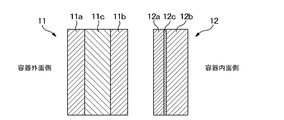
- the outer layer 11 When the outer layer 11 is composed of three or more layers, the innermost layer is the innermost layer, and the outermost layer is the outermost layer. As shown in FIG. 3, the outer layer 11 preferably includes a repro layer 11c between the innermost layer 11b and the outermost layer 11a.
- the repro layer refers to a layer that is used by recycling burrs that are produced when a container is molded.
- lubricant those generally marketed as a lubricant can be used, and any of hydrocarbon-based, fatty acid-based, aliphatic amide-based, metal soap-based may be used, and two or more types may be used in combination. Good.
- hydrocarbon lubricant include liquid paraffin, paraffin wax, and synthetic polyethylene wax.
- fatty acid lubricants include stearic acid and stearyl alcohol.
- Examples of the aliphatic amide-based lubricant include fatty acid amides of stearic acid amide, oleic acid amide, and erucic acid amide, and alkylene fatty acid amides of methylene bis stearic acid amide and ethylene bis stearic acid amide.
- Examples of metal soap lubricants include metal stearates.
- the innermost layer of the outer layer 11 is a layer in contact with the inner layer 12, and the peelability between the outer layer 11 and the inner layer 13 can be improved by adding a lubricant to the innermost layer of the outer layer 11.
- the outermost layer of the outer layer 11 is a layer that comes into contact with the mold during blow molding, and the release property can be improved by containing a lubricant in the outermost layer of the outer layer 11.
- One or both of the innermost layer and the outermost layer of the outer layer 11 can be formed of a random copolymer between propylene and another monomer. Thereby, the shape restoration property, transparency, and heat resistance of the outer layer 11 that is the outer shell can be improved.
- the random copolymer has a content of monomers other than propylene of less than 50 mol%, preferably 5 to 35 mol%. Specifically, this content is, for example, 5, 10, 15, 20, 25, 30 mol%, and may be within a range between any two of the numerical values exemplified here.
- the monomer copolymerized with propylene may be any monomer that improves the impact resistance of the random copolymer when compared with a polypropylene homopolymer, and ethylene is particularly preferable.
- the ethylene content is preferably 5 to 30 mol%, specifically, for example, 5, 10, 15, 20, 25, 30 mol%, and the numerical values exemplified here It may be within the range between any two.
- the weight average molecular weight of the random copolymer is preferably 100,000 to 500,000, and more preferably 100,000 to 300,000. Specifically, the weight average molecular weight is, for example, 10, 15, 20, 25, 30, 35, 40, 45, 500,000, and is within a range between any two of the numerical values exemplified here. Also good.
- the tensile modulus of the random copolymer is preferably 400 to 1600 MPa, more preferably 1000 to 1600 MPa. This is because the shape restoring property is particularly good when the tensile elastic modulus is in such a range.
- the tensile elastic modulus is, for example, 400, 500, 600, 700, 800, 900, 1000, 1100, 1200, 1300, 1400, 1500, 1600 MPa, and between any two of the numerical values exemplified here It may be within the range.
- the outer layer 11 may be configured by mixing a random copolymer with a flexible material such as linear low density polyethylene.
- the material to be mixed with the random copolymer is preferably mixed so as to be less than 50% by weight with respect to the whole mixture so as not to significantly inhibit the effective characteristics of the random copolymer.
- the outer layer 11 can be made of a material in which a random copolymer and linear low-density polyethylene are mixed at a weight ratio of 85:15.
- the inner layer 12 includes an EVOH layer 13a provided on the container outer surface side, an inner surface layer 12b provided on the container inner surface side of the EVOH layer 12a, and an adhesive layer 12c provided between the EVOH layer 12a and the inner surface layer 12b. .
- the gas barrier property and the peelability from the outer layer 11 can be improved.
- the EVOH layer 12a is a layer made of an ethylene-vinyl alcohol copolymer (EVOH) resin, and is obtained by hydrolysis of ethylene and vinyl acetate copolymer.
- EVOH ethylene-vinyl alcohol copolymer
- the ethylene content of the EVOH resin is, for example, 25 to 50 mol%, and is preferably 32 mol% or less from the viewpoint of oxygen barrier properties.
- the EVOH layer 12a preferably contains an oxygen absorbent. By containing the oxygen absorbent in the EVOH layer 12a, the oxygen barrier property of the EVOH layer 12a can be further improved.
- the melting point of the EVOH resin is preferably higher than the melting point of the random copolymer constituting the outer layer 11.
- the outside air introduction hole 15 is preferably formed in the outer layer 11 using a heating type punching device, but the outside air introduction hole 15 is formed in the outer layer 11 by making the melting point of the EVOH resin higher than the melting point of the random copolymer. When forming, the hole is prevented from reaching the inner layer 13. From this point of view, the difference between (melting point of EVOH) ⁇ (melting point of random copolymer layer) should be large, preferably 15 ° C. or higher, and particularly preferably 30 ° C. or higher.
- the difference in melting point is, for example, 5 to 50 ° C., specifically, for example, 5, 10, 15, 20, 25, 30, 35, 40, 45, 50 ° C., and any of the numerical values exemplified here. Or within a range between the two.
- the inner surface layer 12b is a layer that comes into contact with the contents of the double container 1, and is, for example, a polyolefin such as low density polyethylene, linear low density polyethylene, high density polyethylene, polypropylene, ethylene-propylene copolymer, and mixtures thereof. It is preferably made of low-density polyethylene or linear low-density polyethylene.
- the tensile elastic modulus of the resin constituting the inner surface layer 12b is preferably 50 to 300 MPa, more preferably 70 to 200 MPa. This is because the inner surface layer 13b is particularly flexible when the tensile elastic modulus is in such a range.
- the tensile modulus is specifically, for example, specifically, for example, 50, 100, 150, 200, 250, 300 MPa, and may be within a range between any two of the numerical values exemplified here. .
- the adhesive layer 12c is a layer having a function of adhering the EVOH layer 12a and the inner surface layer 12b.
- an acid-modified polyolefin in which a carboxyl group is introduced into the above-described polyolefin eg, maleic anhydride-modified polyethylene
- EVA ethylene vinyl acetate copolymer
- An example of the adhesive layer 12c is a mixture of low-density polyethylene or linear low-density polyethylene and acid-modified polyethylene.
- the layer structure of the container main body 2 is as described above.
- a male screw part is provided in the mouth part 4, and a cap (lid) having a female screw is attached to the male screw part (illustrated). Is omitted). If a cap having an inner ring is used, the outer surface of the inner ring abuts against the abutment surface of the mouth portion 4, thereby preventing leakage of contents.
- a concave portion 7a is formed in the outer layer 11, and an air introduction hole 15 is formed therein.
- the air introduction hole 15 is a through hole provided only in the outer layer 11 and does not reach the inner layer 12. Then, air is introduced from the air introduction hole 15, whereby an intermediate space 21 is formed between the outer layer 11 that is an outer shell and the inner layer 12 that is an inner bag. That is, the intermediate space 21 and the external space S are communicated with each other by the atmosphere introduction hole 15.
- the hydrophobic filter F is attached so as to close the air introduction hole 15, whereby the air introduction hole 15. To prevent water from entering.
- the delamination container often employs shower cooling for cooling after so-called hot-packing.
- shower cooling is performed after hot pack, there is a possibility that a negative pressure is generated between the outer layer 11 and the inner layer 12 and water is sucked from the air introduction hole 15.
- the hydrophobic filter F has a property of repelling water, and by adhering it, it is possible to prevent water from entering from the air introduction hole 15.
- the characteristics required for the hydrophobic filter F are, for example, as follows. (1) Air is allowed to pass but water (liquid) is not allowed to pass (2) Since the role similar to that of the air introduction valve is necessary, it is better that the air permeability is less. However, if air is not allowed to pass through at all, air does not enter between the outer layer 11 and the inner layer 12, which is inappropriate. It is also necessary to consider the balance of breathability. (3) When mounting by ultrasonic welding, the material should be suitable for ultrasonic welding (no fine powder should be generated during ultrasonic welding). By using the hydrophobic filter F that satisfies these requirements, it is possible to control internal pressure maintenance during squeeze and external air introduction during restoration.
- the hydrophobic filter F for example, a nonwoven fabric made of polypropylene is preferable. Since the nonwoven fabric made of polypropylene is hydrophobic, it repels water and has good air permeability.
- the nonwoven fabric made of polypropylene preferably has a basis weight of 160 g / m 2 to 250 g / m 2 , and by setting the basis weight within this range, it is possible to ensure good air permeability and reliably prevent water from entering. Can do.
- the hydrophobic filter F may be a laminate of a hydrophobic microporous membrane and a nonwoven fabric.
- FIG. 6 shows an example of a hydrophobic filter F in which a hydrophobic microporous membrane F1 and a nonwoven fabric F2 are laminated.
- the hydrophobic microporous membrane F1 is a membrane formed of polyethylene terephthalate (PET), polycarbonate, or the like, with pores formed therein. And liquids do not penetrate.
- PET polyethylene terephthalate
- the pores formed in the microporous membrane F1 penetrate the membrane at various angles, and the shape thereof is cylindrical.
- the density of the pores is about 10 5 to 10 9 / cm 2 , and the diameter of the pores is about 0.1 ⁇ m to 10 ⁇ m.
- pores are formed by first subjecting a membrane formed of polyethylene terephthalate (PET) or polycarbonate to ion bombardment by heavy ion bombardment and then chemical etching. Can be formed. By applying ion bombardment, scratches are formed on the surface of the membrane, and pores are formed by chemical etching starting from the scratches.
- PET polyethylene terephthalate
- etching etching
- the nonwoven fabric F2 is reinforced by being lined with the microporous membrane F1.
- the material of the non-woven fabric F2 can be arbitrarily selected.
- a non-woven fabric made of hydrophobic polypropylene can be used.
- hydrophobic filter F in which the hydrophobic microporous membrane F1 and the nonwoven fabric F2 are laminated, a commercially available filter can be used, and examples thereof include trade names M2657 and RoTrac manufactured by Oxyphen. .
- the air permeability and thickness of representative examples of hydrophobic filters are as follows.
- the present invention is not limited to these, and any of those having good air permeability, such as water, can be used for the hydrophobic filter F.
- the hydrophobic filter F may be attached to a portion where the air introduction hole 15 of the double container is formed by adhesion or heat welding.
- the outer layer 11 constituting the double container may be melted. It is difficult to apply because there are.
- high-frequency welding requires a metal film serving as a heat source, and is difficult to apply to the attachment of the hydrophobic filter F.
- the hydrophobic filter F is preferably attached to the double container by ultrasonic welding.
- a horn is brought into contact with the back surface of the hydrophobic filter F, and ultrasonic welding and pressure can be applied to instantly weld.
- the welded portion of the double container is soft, so it is easy to dent, and it may be difficult to make the horn contact uniformly. In such a case, if the shape is maintained by blowing air into the double container and applying an internal pressure, the contact of the horn and the ultrasonic welding can be performed smoothly.
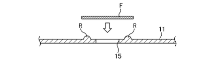
- FIG. 7 shows how the rib R is formed on the outer layer 11 and the hydrophobic filter F is ultrasonically welded.
- the rib R may be formed in a circle around the atmosphere introduction hole 15 with a diameter slightly smaller than the diameter of the hydrophobic filter F.
- the height of the rib R is preferably 0.15 mm or more, for example, about 0.25 mm.
- the inner layer 12 when the inner layer 12 is in contact with the outer layer 11 during ultrasonic welding of the hydrophobic filter F, there is a possibility that a hole is opened in the inner layer 12 due to ultrasonic vibration. Therefore, in ultrasonic welding, it is preferable that the inner layer 12 escapes from the outer layer 11 in the vicinity of the attachment portion of the hydrophobic filter F.
- the air introduction hole 15 is preferably 3 to 4 mm in diameter. If the diameter of the air introduction hole 15 is too small, the restoration of the outer layer 11 becomes worse. On the other hand, if the diameter of the air introduction hole 15 is too large, it is difficult to apply an internal pressure between the outer layer 11 and the inner layer 12 and it may be difficult to discharge. However, since the diameter of the air introduction hole 15 is also related to the air permeability of the hydrophobic filter F, it is preferable to set it appropriately in consideration of the air permeability of the selected hydrophobic filter F.
- the above-described hydrophobic filter F is preferably attached so as to block the air introduction hole 15 even when the air introduction hole 15 is provided with a valve member. This is because when the valve member is simply attached, water easily enters when the water touches.
- FIG. 8 shows an embodiment of a double container (laminated peeling container) having a valve member.
- the configuration of the container body 2 is the same as that of the previous embodiment, and here, the atmosphere introduction hole 15 in which the valve member is installed will be described.
- the valve member 5 is inserted into the outside air introduction hole 15 and is slidably movable with respect to the outside air introduction hole 15.
- the valve member 5 is provided on the intermediate space 21 side of the shaft part 5 a and from the shaft part 5 a.
- a cover portion 5c having a large cross-sectional area and a locking portion 5b provided on the outer space S side of the shaft portion 5a and preventing the valve member 5 from entering the intermediate space 21 are provided.
- the lid portion 5c is configured to substantially close the outside air introduction hole 15 when the outer layer 11 is compressed, and has a shape in which a cross-sectional area becomes smaller as it approaches the shaft portion 5a. Moreover, the latching
- the outer layer 11 When the outer layer 11 is further compressed in this state, the pressure in the intermediate space 21 increases, and as a result, the inner layer 12 is compressed and the contents in the inner layer 12 are discharged. Further, when the compressive force applied to the outer layer 11 is released, the outer layer 11 tries to recover by its own elasticity. At this time, the lid portion 5 c is separated from the outside air introduction hole 15, the outside air introduction hole 15 is released from being blocked, and outside air is introduced into the intermediate space 21.
- the locking portion 5b is provided with a protrusion 5d at a portion that comes into contact with the outer layer 11, and the protrusion 5d comes into contact with the outer layer 11 A gap is provided between the outer layer 11 and the locking portion 5b.
- a groove may be provided in the locking portion 5b to prevent the locking portion 5b from closing the outside air introduction hole 15.
- the valve member 5 can be mounted on the container body 2 by inserting the lid 5c into the intermediate space 21 while the lid 5c pushes the outside air introduction hole 15 wide. Therefore, it is preferable that the tip of the lid portion 5c has a tapered shape. Such a valve member 5 is excellent in productivity because it can be mounted simply by pushing the lid 5c into the intermediate space 21 from the outside of the container body 2.
- the housing part 3 is covered with a shrink film after the valve member 5 is attached.
- the valve member 5 is mounted in the mounting recess 7 a provided in the housing portion 3 so that the valve member 5 does not interfere with the shrink film.
- an air flow groove 7b extending from the mounting recess 7a in the direction of the mouth 4 is provided so that the mounting recess 7a is not sealed with the shrink film.
- the mounting recess 7a has a two-stage structure
- the valve member 5 is attached to the lower stage 7c
- the hydrophobic filter F is attached to the upper stage 7d. Intrusion of water from the air introduction hole 15 can be reliably prevented.
- the product filled with the contents is tilted and the side surface of the outer layer 11 is held and compressed to discharge the contents.
- the compressive force applied to the outer layer 11 becomes the compressive force of the inner layer 12 as it is, and the inner layer 12 is compressed and the contents are compressed. Discharged.
- the cap 23 incorporates a check valve (not shown) and can discharge the contents in the inner layer 12, but cannot take outside air into the inner layer 12. Therefore, if the compressive force applied to the outer layer 11 after discharging the contents is removed, the outer layer 11 tries to return to its original shape by its own restoring force, but the inner layer 12 remains deflated and only the layer 11 expands. Become. Then, as shown in FIG. 10 (d), the inside of the intermediate space 21 between the inner layer 12 and the outer layer 11 is in a reduced pressure state, and outside air is introduced into the intermediate space 21 through the outside air introduction hole 15 formed in the outer layer 11. . When the intermediate space 21 is in a depressurized state, the valve member 5 is not pressed against the air introduction hole 15, so that the introduction of outside air is not hindered.
- a molten laminated parison 31 having a laminated structure corresponding to the double container 1 to be produced is formed as a die head.
- the melted laminated parison 31 is set in blow molds 33 and 34, and the molds 33 and 34 are closed.
- the blow nozzle 35 is inserted into the opening on the mouth 4 side of the double container 1 and the molds are clamped, and the inside of the cavities of the split molds 33 and 34 is placed. Blow in air.
- the split molds 33 and 34 are opened, and the blow-molded product (double container 1 which is a delamination container) is taken out.
- the split molds 33 and 34 have a cavity shape such that the shape of each part of the blow molded product is a predetermined shape. Further, the split molds 33 and 34 are provided with a pinch-off portion below the bottom seal portion, and remove a lower burr formed below the bottom seal portion.
- the double container 1 having the outer layer 11 and the inner layer 12 is formed by the above steps (container body forming step).
- the taken out double container 1 is aligned.
- the upper tubular body 41 remains as a burr in the mouth portion 4 of the double container 1 so as to extend the mouth 4, and this portion needs to be removed by cutting as an unnecessary portion. .
- the upper cylindrical body 41 has been cut by cutting with a blade so far.
- the inner layer 12 is thin, it is understood that a phenomenon occurs in which the inner layer 12 is peeled off from the outer layer 11 along with the cutting. I came. As a result of studies by the present inventors, it has been found that the occurrence of this phenomenon is remarkable particularly when the thickness of the inner layer 12 is 150 ⁇ m or less.
- the upper cylindrical body 41 is cut and removed by cutting using a laser. As shown in FIG. 12, the resin-made upper cylindrical body 41 is cut and removed by irradiating the laser beam L so that the focal point coincides with the cut portion. In addition, when irradiating the laser beam L from one direction, the upper cylindrical body 41 is rotated over the entire circumference by rotating the double container 1 or rotating the light source of the laser light L around the double container 1. It is possible to cut.
- the laser beam to be used may be anything as long as it can cut the resin laminate constituting the double container 1, and a gas laser such as an excimer laser, a solid laser, a dye laser, or the like can be used.
- a gas laser such as an excimer laser, a solid laser, a dye laser, or the like
- a carbon dioxide laser or a YAG laser is suitable.
- a molten resin piece 42 called “resin dripping” may be formed at the cutting position (inner diameter side of the mouth portion 4). If the molten resin piece 42 is formed inside the mouth portion 4 and interferes with, for example, the inner ring of the cap, there is a risk of hindering the mounting of the cap. Therefore, the molten resin piece 42 is positioned outside the inner ring contact surface 4a of the mouth part 4 by devising the shape of the mouth part 4 or making the laser irradiation conditions appropriate. Thereby, the molten resin piece 42 does not come into contact with the inner ring of the cap, and the mounting of the cap having the inner ring is not hindered.
Abstract
Description
(1)空気は通すが水(液体)は通さないこと
(2)大気導入弁と同様の役割が必要であることから、通気性は少ないほうが良い。ただし、全く空気を通さないと、外層11と内層12の間に空気が入らないので、不適である。また、通気性のバランスも考慮する必要がある。
(3)超音波溶着による取り付けを行う場合、超音波溶着で適する材質であること(超音波溶着の際に微細粉が発生しないこと)
これら要件を満たす疎水性フィルタFを用いることにより、スクイズ時の内圧維持と、復元時の外気導入をコントロールすることが可能である。
・オクシフェン社製、商品名M2657:>3.3l/(min cm2 bar)、t=155±40μm
・オクシフェン社製、商品名R5587:>6.5l/(min cm2 bar)、t=155±40μm
・オクシフェン社製、商品名M2810:8±2.5l/(min cm2 bar)、t=140±40μm
・オクシフェン社製、商品名M2803:17.5±3.8l/(min cm2 bar)、t=140±40μm
・オクシフェン社製、商品名M2802:35±8l/(min cm2 bar)、t=140±40μm
Claims (5)
- 外殻と内袋とを有し、内袋に収容される内容物の減少に伴って前記内袋が収縮する二重容器であって、
前記外殻には空気導入孔が形成されるとともに、空気を透過し水を遮断する疎水性フィルタが前記空気導入孔を塞ぐように設けられていることを特徴とする二重容器。 - 前記疎水性フィルタは、ポリプロピレンの不織布により形成されていることを特徴とする請求項1記載の二重容器。
- 前記ポリプロピレンの不織布の目付けが160g/m2~250g/m2であることを特徴とする請求項2記載の二重容器。
- 前記疎水性フィルタは、疎水性の微多孔膜と不織布を積層したものであることを特徴とする請求項1記載の二重容器。
- 前記大気導入孔は、外殻と内袋の間の中間空間と外部空間との間の空気の出入りを調節する弁部材を備えることを特徴とする請求項1から4のいずれか1項記載の二重容器。
Priority Applications (4)
| Application Number | Priority Date | Filing Date | Title |
|---|---|---|---|
| EP16800115.4A EP3305673B1 (en) | 2015-05-28 | 2016-05-27 | Double container |
| KR1020177036836A KR102005246B1 (ko) | 2015-05-28 | 2016-05-27 | 이중 용기 |
| US15/577,086 US10479545B2 (en) | 2015-05-28 | 2016-05-27 | Double container |
| CN201680029817.9A CN107614387B (zh) | 2015-05-28 | 2016-05-27 | 双层容器 |
Applications Claiming Priority (6)
| Application Number | Priority Date | Filing Date | Title |
|---|---|---|---|
| JP2015-108399 | 2015-05-28 | ||
| JP2015108844A JP2016222264A (ja) | 2015-05-28 | 2015-05-28 | 二重容器の製造方法 |
| JP2015108399 | 2015-05-28 | ||
| JP2015-108844 | 2015-05-28 | ||
| JP2015234032A JP6675069B2 (ja) | 2015-05-28 | 2015-11-30 | 二重容器 |
| JP2015-234032 | 2015-11-30 |
Publications (1)
| Publication Number | Publication Date |
|---|---|
| WO2016190411A1 true WO2016190411A1 (ja) | 2016-12-01 |
Family
ID=57394031
Family Applications (1)
| Application Number | Title | Priority Date | Filing Date |
|---|---|---|---|
| PCT/JP2016/065701 WO2016190411A1 (ja) | 2015-05-28 | 2016-05-27 | 二重容器 |
Country Status (1)
| Country | Link |
|---|---|
| WO (1) | WO2016190411A1 (ja) |
Cited By (1)
| Publication number | Priority date | Publication date | Assignee | Title |
|---|---|---|---|---|
| JP2020011739A (ja) * | 2018-07-13 | 2020-01-23 | 東洋製罐グループホールディングス株式会社 | 二重容器及びその製造方法 |
Citations (5)
| Publication number | Priority date | Publication date | Assignee | Title |
|---|---|---|---|---|
| JPH03133748A (ja) * | 1989-10-13 | 1991-06-06 | Riyouichi Kitase | 注出容器 |
| JPH05124675A (ja) * | 1991-10-23 | 1993-05-21 | Asahi Chem Ind Co Ltd | 各種薬剤の包材 |
| JP2006335398A (ja) * | 2005-05-31 | 2006-12-14 | Yoshino Kogyosho Co Ltd | 内側層が剥離可能な積層容器その成形方法 |
| WO2014157258A1 (ja) * | 2013-03-29 | 2014-10-02 | 株式会社吉野工業所 | 積層ボトル |
| WO2014202278A1 (de) * | 2013-06-18 | 2014-12-24 | Aptar Radolfzell Gmbh | Spender für flüssigkeiten |
-
2016
- 2016-05-27 WO PCT/JP2016/065701 patent/WO2016190411A1/ja active Application Filing
Patent Citations (5)
| Publication number | Priority date | Publication date | Assignee | Title |
|---|---|---|---|---|
| JPH03133748A (ja) * | 1989-10-13 | 1991-06-06 | Riyouichi Kitase | 注出容器 |
| JPH05124675A (ja) * | 1991-10-23 | 1993-05-21 | Asahi Chem Ind Co Ltd | 各種薬剤の包材 |
| JP2006335398A (ja) * | 2005-05-31 | 2006-12-14 | Yoshino Kogyosho Co Ltd | 内側層が剥離可能な積層容器その成形方法 |
| WO2014157258A1 (ja) * | 2013-03-29 | 2014-10-02 | 株式会社吉野工業所 | 積層ボトル |
| WO2014202278A1 (de) * | 2013-06-18 | 2014-12-24 | Aptar Radolfzell Gmbh | Spender für flüssigkeiten |
Cited By (2)
| Publication number | Priority date | Publication date | Assignee | Title |
|---|---|---|---|---|
| JP2020011739A (ja) * | 2018-07-13 | 2020-01-23 | 東洋製罐グループホールディングス株式会社 | 二重容器及びその製造方法 |
| JP7192278B2 (ja) | 2018-07-13 | 2022-12-20 | 東洋製罐グループホールディングス株式会社 | 二重容器及びその製造方法 |
Similar Documents
| Publication | Publication Date | Title |
|---|---|---|
| KR102005246B1 (ko) | 이중 용기 | |
| JP7108206B2 (ja) | 積層剥離容器 | |
| US10822135B2 (en) | Delaminatable container | |
| JP6421458B2 (ja) | 積層剥離容器 | |
| WO2017179529A1 (ja) | 積層剥離容器 | |
| US10723500B2 (en) | Delamination container, method for attaching cap to delamination container, and method for manufacturing delamination container | |
| JP2019055825A (ja) | 積層剥離容器 | |
| WO2010073650A1 (ja) | プラスチック容器及びその製造方法 | |
| JP6675069B2 (ja) | 二重容器 | |
| JP6451087B2 (ja) | 積層剥離容器 | |
| WO2016190411A1 (ja) | 二重容器 | |
| JP2019206397A (ja) | 積層剥離容器 | |
| WO2016039134A1 (ja) | 被加工物の加工方法、穴あけドリル | |
| JP2016222264A (ja) | 二重容器の製造方法 | |
| JP6880386B2 (ja) | 積層剥離容器 | |
| JP2016074466A (ja) | 積層剥離容器 | |
| JP2017165452A (ja) | 二重容器 | |
| JP2018052578A (ja) | 多層容器及び多層容器の外層部と内層部を分離する方法 | |
| JP2018034850A (ja) | キャップ付き容器 | |
| JP2015127237A (ja) | 積層剥離容器 | |
| JP7104875B2 (ja) | 二重容器 |
Legal Events
| Date | Code | Title | Description |
|---|---|---|---|
| 121 | Ep: the epo has been informed by wipo that ep was designated in this application |
Ref document number: 16800115 Country of ref document: EP Kind code of ref document: A1 |
|
| WWE | Wipo information: entry into national phase |
Ref document number: 15577086 Country of ref document: US |
|
| NENP | Non-entry into the national phase |
Ref country code: DE |
|
| ENP | Entry into the national phase |
Ref document number: 20177036836 Country of ref document: KR Kind code of ref document: A |
|
| WWE | Wipo information: entry into national phase |
Ref document number: 2016800115 Country of ref document: EP |