WO2016190016A1 - 光学部材、光導光部材、及び、光学部材を生産する方法 - Google Patents
光学部材、光導光部材、及び、光学部材を生産する方法 Download PDFInfo
- Publication number
- WO2016190016A1 WO2016190016A1 PCT/JP2016/062774 JP2016062774W WO2016190016A1 WO 2016190016 A1 WO2016190016 A1 WO 2016190016A1 JP 2016062774 W JP2016062774 W JP 2016062774W WO 2016190016 A1 WO2016190016 A1 WO 2016190016A1
- Authority
- WO
- WIPO (PCT)
- Prior art keywords
- light
- carbon
- optical member
- carbon black
- silicone resin
- Prior art date
- Legal status (The legal status is an assumption and is not a legal conclusion. Google has not performed a legal analysis and makes no representation as to the accuracy of the status listed.)
- Ceased
Links
Images



Classifications
-
- G—PHYSICS
- G02—OPTICS
- G02B—OPTICAL ELEMENTS, SYSTEMS OR APPARATUS
- G02B6/00—Light guides; Structural details of arrangements comprising light guides and other optical elements, e.g. couplings
- G02B6/0001—Light guides; Structural details of arrangements comprising light guides and other optical elements, e.g. couplings specially adapted for lighting devices or systems
- G02B6/0011—Light guides; Structural details of arrangements comprising light guides and other optical elements, e.g. couplings specially adapted for lighting devices or systems the light guides being planar or of plate-like form
- G02B6/0013—Means for improving the coupling-in of light from the light source into the light guide
- G02B6/0015—Means for improving the coupling-in of light from the light source into the light guide provided on the surface of the light guide or in the bulk of it
- G02B6/0016—Grooves, prisms, gratings, scattering particles or rough surfaces
-
- G—PHYSICS
- G02—OPTICS
- G02B—OPTICAL ELEMENTS, SYSTEMS OR APPARATUS
- G02B6/00—Light guides; Structural details of arrangements comprising light guides and other optical elements, e.g. couplings
- G02B6/24—Coupling light guides
- G02B6/241—Light guide terminations
- G02B6/243—Light guide terminations as light absorbers
-
- G—PHYSICS
- G02—OPTICS
- G02B—OPTICAL ELEMENTS, SYSTEMS OR APPARATUS
- G02B1/00—Optical elements characterised by the material of which they are made; Optical coatings for optical elements
- G02B1/04—Optical elements characterised by the material of which they are made; Optical coatings for optical elements made of organic materials, e.g. plastics
-
- G—PHYSICS
- G02—OPTICS
- G02B—OPTICAL ELEMENTS, SYSTEMS OR APPARATUS
- G02B1/00—Optical elements characterised by the material of which they are made; Optical coatings for optical elements
- G02B1/04—Optical elements characterised by the material of which they are made; Optical coatings for optical elements made of organic materials, e.g. plastics
- G02B1/045—Light guides
-
- G—PHYSICS
- G02—OPTICS
- G02B—OPTICAL ELEMENTS, SYSTEMS OR APPARATUS
- G02B5/00—Optical elements other than lenses
- G02B5/003—Light absorbing elements
-
- G—PHYSICS
- G02—OPTICS
- G02B—OPTICAL ELEMENTS, SYSTEMS OR APPARATUS
- G02B6/00—Light guides; Structural details of arrangements comprising light guides and other optical elements, e.g. couplings
- G02B6/0001—Light guides; Structural details of arrangements comprising light guides and other optical elements, e.g. couplings specially adapted for lighting devices or systems
- G02B6/0096—Light guides; Structural details of arrangements comprising light guides and other optical elements, e.g. couplings specially adapted for lighting devices or systems the lights guides being of the hollow type
Definitions
- the present invention relates to an optical member, a light guiding member, and a method of producing an optical member, and more particularly to an optical member that attenuates incident light, which is used adjacent to a light guiding portion that transmits incident light.
- the sensitivity of luminescence analysis utilizing the phenomenon of luminescence of substances, molecules and atoms is very high.
- a sample is irradiated with light, and analysis using light emitted from the sample is also performed.
- a light analysis there are an absorbance method and a laser organic fluorescence method (Laser Induced Fluorescence (LIF)).
- the distance between the light source for irradiating the sample with light and the detector for monitoring the observation light from the sample becomes short in the device.
- a condenser lens or an optical filter is provided in a light guiding path that constitutes an irradiation optical system that guides irradiation light from a light source to a sample, and a light guiding path that constitutes an observation light collecting optical system that guides observation light from a sample to a detector.
- stray light which may become noise in measurement, such as reflected light or scattered light generated when light travels in the light guide path in the device, becomes remarkable as the device is miniaturized.
- Such stray light is also generated on the inner wall of the device housing.
- Patent Document 1 relates to the LIF device.
- a light guiding path constituting the irradiation optical system and a part of the light guiding path constituting the observation light collecting optical system are filled with a resin transparent to the irradiation light and the observation light.
- a resin is further provided so as to surround the transparent resin constituting these light guide paths.
- the resin contains a pigment.
- the pigment has a property of absorbing stray light.
- the pigment content is set to an amount that absorbs at least all stray light.
- the material of resin of transparent resin and pigment containing resin is the same.
- the following actions and effects can be obtained.
- the pigment is a particle and has a characteristic of absorbing stray light
- a part of the stray light incident on the pigment is scattered.
- scattering of part of the stray light may be Mie scattering, Rayleigh scattering, or geometric scattering.
- Patent Document 1 focuses on the absorption characteristics of the pigment. However, the influence of scattering of stray light by pigment particles is not sufficiently taken into consideration.
- this invention aims at provision of the optical member etc. which becomes possible to suppress scattering of the stray light by a pigment, even if it is used adjacent to the light guide part which permeate
- an optical member for reducing the incident light which is used to be adjacent to a light guiding portion for transmitting the incident light, wherein the optical member is formed on a specific region in silicone resin. It is an optical member which comprises a carbon particle dispersed part in which carbon particles are dispersed, and the carbon particle is a stray light scattering suppression particle which suppresses the intensity of light which is incident on the carbon particle and scattered.
- a second aspect of the present invention is the optical member according to the first aspect, wherein the carbon particles of the carbon particle dispersed portion contain carbon black particles, and the carbon black of the carbon particle dispersed portion
- the particles are optical members which are only carbon black particles having a minor diameter of 2 ⁇ m or less.
- a third aspect of the present invention is the optical member according to the first or second aspect, wherein the carbon particles of the carbon particle dispersed portion contain carbon nanotubes.
- a fourth aspect of the present invention is the optical member according to the second or third aspect, wherein the specific region is the light guide portion when the optical member is used adjacent to the light guide portion.
- the optical member is a region corresponding to a region from the boundary between the light source and the optical member to the depth of the absorption length of the specific light.
- a fifth aspect of the present invention is the optical member according to the fourth aspect, wherein the specific light is noise light different from the incident light.
- a sixth aspect of the present invention is a light guiding member for guiding incident light, wherein the light guiding portion transmits the incident light and has a silicone resin transparent to the incident light at least in part;
- a stray light absorbing portion adjacent to the light guiding portion and having a carbon particle dispersed silicone resin in which carbon particles are dispersed in a silicone resin having the same refractive index as the transparent silicone resin, and the carbon particles
- It is a light guiding member which is a stray light scattering suppression particle which suppresses the intensity of light which is incident and scattered.
- a seventh aspect of the present invention is the light guiding member according to the sixth aspect, wherein the carbon particles of the carbon particle dispersed portion contain carbon black particles, and the carbon of the carbon particle dispersed portion is included.
- the black particles are only carbon black particles having a minor diameter of 2 ⁇ m or less.
- An eighth aspect of the present invention is the light guiding member according to the sixth or seventh aspect, wherein the carbon particles of the carbon particle dispersed portion contain carbon nanotubes.
- a ninth aspect of the present invention is a method of producing an optical member for reducing the incident light, which is used to be adjacent to a light guide portion for transmitting the incident light, wherein the uncured undispersed silicone resin before curing is used.
- a method of producing an optical member, wherein the concentration of the carbon black dispersed in the uncured undispersed silicone resin is 5 wt% or more and 20 wt% or less.
- each aspect of the present invention it is possible to provide an optical member or the like that reduces light that is less likely to be scattered even when used adjacent to a light guide that transmits incident light.
- the second aspect of the present invention it is possible to use both a resin in which carbon black is dispersed adjacent to a light guide that transmits incident light to achieve both suppression of stray light scattering and intensity attenuation of stray light. It becomes.
- the particle diameter of pigments such as carbon black refers to the minor diameter of the particles.
- the intensity of scattering by Rayleigh scattering is proportional to (1 / ⁇ 4 ).
- the longer the wavelength of the incident light the smaller the scattering intensity.
- the scattered light intensity is proportional to (1 / ⁇ 2 ), and has smaller wavelength dependence than Rayleigh scattering. Therefore, light of any wavelength is scattered relatively equally. Therefore, it is preferable to make the particle diameter as small as possible the influence of Mie scattering.
- the present invention makes it possible to suppress the influence of scattering when stray light is incident on a pigment by appropriately setting the content of the carbon black pigment in the silicone resin based on the findings of the present inventors. is there.
- scattering suppression of stray light and intensity attenuation of stray light can be compatible by using a resin in which carbon nanotubes are dispersed adjacent to a light guiding portion that transmits incident light. It becomes.
- carbon-based materials other than carbon black it is unknown as to what kind of scattering suppression effect can be expected. If the materials are different, the characteristics may also be greatly different.
- the effect of the third aspect of the present invention is based on the optical properties of carbon nanotubes that the inventors have clarified through research and development.
- the fourth aspect of the present invention it is easy to particularly suppress the scattering of light entering the optical member from the light guide.
- the wavelength used for light measurement is approximately in the range of ultraviolet light to visible light (200 to 780 nm). It becomes easy to adjust an optical member based on the wavelength of the noise light which should suppress especially scattering in light measurement.
- the discoid sample 1 is a discoid transparent silicone resin, and has a transparent semicircular part 3 made of a transparent silicone resin and a pigment semicircular part 5 made of a silicone resin containing a pigment.
- a transparent silicone resin PDMS resin (made by Shin-Etsu Silicone (registered trademark): silicone impression material SIM-360) was used.
- the pigment-containing silicone resin was formed by dispersing the pigment in the PDMS. Specifically, first, carbon black (manufactured by Shin-Etsu Silicone (registered trademark): KE-COLOR-BL) is added to the main component of the above SIM-360, and then it is added to a revolution automatic mixer (manufactured by KURABO (registered trademark: KK-505) Stirred. The stirring operation was carried out twice under a stirring condition of revolution number 1440 rpm, rotation number 1008 rpm and stirring time 200 sec.
- carbon black manufactured by Shin-Etsu Silicone (registered trademark): KE-COLOR-BL
- KURABO registered trademark: KK-505
- the concentration of carbon black dispersed in the PDMS is 1 wt%, 5 wt%, 10 wt%, and 20 wt%.
- the curing time of PDMS was 1 hour.
- the carbon black added to the main agent of the SIM-360 exhibits remarkable aggregation in the main agent of the SIM-360, and the main agent and the carbon black It came to separate in multiple places. Even if it separates by the revolution automatic mixer in this separated state, the separation of the above-mentioned main ingredient and carbon black is not canceled, and it was impossible to disperse carbon black to the above-mentioned main ingredient. Therefore, it was found that in order to prevent the separation of the main agent and carbon black, the carbon black concentration should be 20 wt% or less.
- the particle size of carbon black was approximately 0.5 to 2.0 ⁇ m.
- the concentration of carbon black is 1 wt%, 5 wt%, and 10 wt%, the particle size of carbon black almost entirely falls within the above range, and the variation in particle size is relatively small.
- the concentration of carbon black is 20 wt%
- the particle size of most carbon blacks falls within the range of about 0.5 to 2.0 ⁇ m as in the cases of 1 wt%, 5 wt% and 10 wt% of carbon black.
- aggregation of carbon black occurred.
- this carbon black aggregation occurred when the concentration of carbon black exceeded 10 wt%.
- the carbon black concentration is 1 wt%, 5 wt%, and 10 wt%, no aggregation occurs, and the characteristics as a silicone resin (rubber) in which carbon black is dispersed can be maintained.
- the curing time of the PDMS resin which is a silicone resin
- the particle size of carbon black even if the carbon black concentration exceeds 20 wt% It may also be possible to prevent separation of the main agent and carbon black from occurring at 2 ⁇ m or less.
- the practical carbon black concentration is 20 wt% or less.
- the interface between the transparent semicircular part 3 and the pigment semicircular part 5 is to be clearly defined to some extent when the concentration of carbon black is 10 wt% and 20 wt%. That is, it was confirmed that carbon black particles were densely packed along the interface.
- FIG. 3 shows an angular characteristic measurement system 11 of the scattered light intensity used for this measurement.
- the disk-shaped sample 1 is placed on a rotation stage 15 having a rotation axis 13.
- the rotating shaft 13 has a branch 17 extending from the rotating shaft 13 in a direction orthogonal to the axial direction of the rotating shaft 13.
- the branch portion 17 is connected to the support 21 of the light source support portion 19.
- the light source support 19 includes a support 21 and a light source fixing unit 23 branched from the support 21.
- a DPSS laser light source 25 for emitting a laser beam with a wavelength of 532 nm is fixed to the light source fixing unit 23.
- the laser beam 27 emitted from the DPSS laser light source 25 travels downward as shown in FIG. 3 and is supported by a reflection mirror 31 supported by a reflection mirror support 29 provided on the rotation shaft 13 of the rotation stage 15. It is folded back and enters the disc-shaped sample 1.
- the reflection mirror 31 is adjusted so that the laser beam 27 is incident at an incident angle of 45 degrees with respect to the interface 7 between the transparent semicircular portion 3 and the pigment semicircular portion 5 of the disk-shaped sample 1 There is.
- the discoid sample 1 is composed of the transparent semicircular portion 3 and the pigment semicircular portion 5 as described above.
- the silicone resin which comprises both semicircle parts is resin of the same kind, the refractive index is also the same. Therefore, interface reflection at the interface 7 of the laser beam 27 incident on the discoid sample 1 does not basically occur.
- the laser beam 27 enters the pigment semicircular portion 5 without being interface-reflected at the interface 7.
- the materials of carbon black and silicone resin are different, and their refractive indices are different from each other. Therefore, the laser beam 27 reaching the carbon black is absorbed or scattered by the carbon black.
- the absorption coefficient of carbon black is 7.2 ⁇ 10 2 / cm for the laser beam 27 at a wavelength of 532 nm. Therefore, the laser beam 27 that has reached the carbon black is strongly absorbed by the carbon black. The laser beam 27 not absorbed by the carbon black is scattered by the carbon black in various directions. Of the scattered light, the light that has progressed from the pigment semicircular part 5 to the transparent semicircular part 3 is emitted from the transparent semicircular part 3 to the outside.
- a scattered light measurement unit 39 is provided having a condensing lens 35 for condensing light and a detector 37 formed of a photodiode for measuring the intensity of the laser beam 27 condensed by the condensing lens 35.
- the scattered light measurement unit 39 limits the light incident on the detector 37 by the slit 33.
- the disk-shaped sample 1, the DPSS laser light source 25 and the reflection mirror 31 are integrated by the light source support 19 and the reflection mirror support 29 connected by the rotating shaft 13 and the branch 17. It is held. Therefore, even when the rotation shaft 13 is rotated, the incident angle of the light of the DPSS laser light sources 25 and the like incident on the disk-shaped sample 1 is maintained.
- the slit 33 fixes the incident angle of the incident light as shown in FIG. Therefore, by rotating the rotation axis 13 of the rotation stage 15, only the intensity of light scattered in a specific angular direction can be measured by the scattered light measurement unit 39. That is, it becomes possible to measure the angular characteristics of the scattered light intensity emitted from the disk-shaped sample 1.
- FIG. 4 is a view showing the angular characteristic distribution of the scattered light intensity in a sample of which the carbon black concentration is (a) 1 wt%, (b) 5 wt%, (c) 10 wt%, (d) 20 wt%.
- the length of the line segment in each angular direction indicates the scattered light intensity. Therefore, the area formed by the curve connecting the tips of the line segments indicates the integrated reflection intensity (scattering intensity) of the laser beam incident on the sample.
- the concentration of carbon black is 1 wt%
- the integrated reflection intensity (scattering intensity) is large. Therefore, in order to absorb stray light in a light guide made of a transparent silicone resin, the light guide is surrounded by a silicone resin in which a pigment (carbon black) is dispersed, and stray light from the light guide is dispersed in the pigment dispersed silicone resin.
- the carbon black is absorbed at a concentration of 1 wt%, it may be considered that the influence of the scattered light from the pigment-dispersed silicone resin can not be ignored.
- the concentration of carbon black is 5 wt%, 10 wt%, and 20 wt%, the integrated reflection intensity (scattering intensity) is small. Therefore, the pigment-dispersed silicone resin for absorbing stray light is considered to be able to perform a sufficient function.
- the reason for the large integrated reflection intensity (scattering intensity) when the concentration of carbon black is 1 wt% is not necessarily clear, but is considered as follows.
- concentration of carbon black is 1 wt%
- the distance between carbon black particles is large, and the influence of multiple scattering is considered to be large. That is, when the scattered light from one carbon black collides with another carbon black and is further scattered, since the distance between each carbon black particle is large, it passes through the space between each carbon black and the transparent semicircular portion It is considered that the probability of progressing to 3 is high.
- silicone resin which is made of a transparent light guide made of a silicone resin and the same material as the transparent silicone resin and in which a pigment (carbon black) having an absorption characteristic for stray light from the light guide is dispersed.
- a pigment-dispersed silicone resin is prepared, and an optical system consisting of a two-layered silicone resin in which the light guide path is surrounded by the pigment-dispersed silicone resin is considered.
- the transparent silicone resin and the pigment-dispersed silicone resin that constitute the light guide are made of the same material, interface reflection of light at the interface between the two resins does not occur. Therefore, stray light which enters the pigment-dispersed silicone resin from the light guide is directly incident on the pigment-dispersed silicone resin, and most of the stray light is absorbed by the carbon black.
- stray light that has reached carbon black but has not been absorbed will be scattered on the carbon black surface. In some cases, part of the scattered light (reflected light) may again enter the light guide.
- an optical system made of silicone resin of the above two-layer structure for reducing the influence of stray light from the light guide has (1) the integral reflection intensity (scattering intensity) in carbon black as small as possible, and (2) carbon black as possible It is desirable for the backscattering intensity to be small.
- the scattering conditions (1) and (2) in an optical system comprising a silicone resin having a two-layer structure are also practical. It turned out that it was lost.
- the particle size of carbon black in the pigment-dispersed silicone resin it is preferable to set the particle size of carbon black in the pigment-dispersed silicone resin to 0.5 to 2.0 ⁇ m. Further, it is preferable to set the concentration of carbon black to 5 to 20 wt%.
- the order of importance is given by the interface shape between the transparent silicone resin and the pigment-dispersed silicone resin that constitute the light guide.
- FIG. 5 is a view showing that desirable scattering conditions are different due to the difference in the state on the light emission side of the light guide.
- the emission end 55 of the light guide 53 through which the light 51 as a signal passes is open without being closed by the pigment-dispersed silicone resin 57.
- the emitting end 55 is a sensor 59 that receives an optical signal (for example, an optical sensor that measures the light intensity).
- the scattered light 61 noise light
- the scattered light 61 noise light
- the scattered light 61 noise light
- the light emitting end 67 of the light guiding portion 65 through which the light 63 which is a signal passes is blocked by the pigment dispersed silicone resin 69 and the light 63 which is a signal is pigment dispersed silicone resin.
- the scattered light 71 (noise light) from the pigment-dispersed silicone resin 69 is desired to be as small as possible and not to travel backward. That is, (2) the smaller the backscattering intensity, the more important.
- the light guiding portion is not necessarily completely filled with a transparent silicone resin, and may have a space.
- the thickness of the silicone resin when the optical density (OD value) was 6 was investigated.
- the wavelength of light was 532 nm.
- the thickness of the transparent light guide and the thickness of the pigment dispersed silicone resin surrounding the upper part of the transparent light guide is about 2 mm. That is, the thickness of the microchip is at least the thickness of the transparent light guide + about 4 mm, and the thickness of the microchip is increased. Therefore, when producing a pigment dispersed silicone resin, it is not preferable to set the carbon black concentration to 1 wt% or less.
- the particle size of carbon black is 0.5 to 2.0 ⁇ m.
- (3) 10 wt% ⁇ C cb ⁇ 20 wt% ⁇ ⁇ ⁇ ⁇ Agglomeration of carbon black may occur.
- the particle size of carbon black in the region where aggregation does not occur is 0.5 to 2.0 ⁇ m.
- the concentration of carbon black is increased to some extent, depending on the concentration, the main agent SIM-360 of PDMS and carbon black come to be completely separated, making it impossible to disperse carbon black in a silicone resin.
- an optical member having a light shielding function an example of the “optical member” and the “stray light absorbing portion” in the claims of the present application
- dispersing carbon black in silicone resin for use in a microchip 5 wt% ⁇ C cb ⁇ 20 wt% is preferable, and 5 wt% ⁇ C cb ⁇ 10 wt% is more preferable.
- carbon black of a desired concentration is added to a main ingredient of silicone impression material SIM-360 before curing (an example of "uncured undispersed silicone resin” in the claims of this application) and stirred. It disperse
- three types of disk-shaped samples 1 were prepared by changing the concentration of carbon nanotubes dispersed in PDMS.
- one type of carbon black was used as a carbon-based material.
- the concentrations of carbon nanotubes dispersed in the PDMS are 0.17 wt%, 0.83 wt%, and 1.7 wt%.
- distributed to said PDMS was 10 wt%.
- the curing time of PDMS was 1 hour.
- the shape of the carbon nanotubes was almost uniform as a whole, the average diameter was 10 to 15 nm, and the average length was 10 ⁇ m.
- the angular characteristics of the scattered light intensity in a sample having a carbon nanotube concentration of 0.17 wt%, 0.83 wt%, 1.7 wt%, and a carbon black concentration of 10 wt% were measured.
- FIG. 6 is a diagram showing the angular characteristic distribution of the scattered light intensity in a sample having a carbon nanotube concentration of 0.17 wt%, 0.83 wt%, 1.7 wt% and a carbon black concentration of 10 wt%.
- the length (distance) from the origin 0 to each curve indicates the scattered light intensity. Therefore, the area of each curve represents the integrated reflection intensity (scattering intensity) of the laser beam incident on the sample.
- the integrated reflection intensity is smaller as compared to when carbon black is used as a pigment.
- the light guide is surrounded by a silicone resin in which a pigment (carbon black) is dispersed, and the light guide is formed.
- a pigment carbon black
- the integrated reflection intensity is small when the concentration of carbon black is 10 wt%, and the pigment-dispersed silicone resin for absorbing stray light can perform a sufficient function.
- the scattered light intensity is smaller than in the case of using carbon black at a concentration of 10 wt%, so when using carbon black, the silicone resin for stray light absorption in which carbon nanotubes are dispersed It is considered to be even better and capable of performing a sufficient function.
- Carbon black generally has a particle structure, but carbon nanotubes have a linear structure. Therefore, it is considered that the relative relationship between the direction (light distribution) of the carbon nanotube dispersed in the silicone resin and the traveling direction of the scattered light is a relationship suitable for the improvement of the scattering suppression effect.
- the integrated reflection intensity (scattering intensity) is 0.83 wt%. Time is the smallest. Therefore, when carbon nanotubes are used, it is considered that the optimum carbon nanotube concentration capable of minimizing the integrated reflection intensity (scattering intensity) is within the concentration range of 0.17 to 1.7 wt%. .
- the integral reflection intensity (scattering intensity) is smaller compared to when carbon black is used as a pigment, and therefore the silicone resin for absorbing stray light in which carbon nanotubes are dispersed is When using carbon black, it is considered to be better and perform a sufficient function.
- the optical system as shown in FIG. 7 was constructed, and the stray light absorption characteristics of the silicone resin for absorbing stray light in which carbon nanotubes were dispersed and the silicone resin for absorbing stray light in which carbon black was dispersed were compared.
- FIG. 7 it comprises a light guide made of a transparent PDMS resin having an area of the incident surface of 2 mm ⁇ 1 mm and a length of 50 mm, and a pigment dispersed silicone resin in which a carbon based pigment surrounding this light guide is dispersed.
- a light guide made of a transparent PDMS resin having an area of the incident surface of 2 mm ⁇ 1 mm and a length of 50 mm
- a pigment dispersed silicone resin in which a carbon based pigment surrounding this light guide is dispersed.
- the transparent silicone resin and the pigment-dispersed silicone resin that constitute the light guide are made of the same material, interface reflection of light at the interface between the two resins does not occur. Therefore, stray light which enters the pigment-dispersed silicone resin from the light guide is directly incident on the pigment-dispersed silicone resin, and most of the stray light is absorbed by the carbon-based pigment.
- a laser beam with a wavelength of 532 nm having a beam diameter of 1 mm is incident from the A end of the optical member.
- part of the laser light may be a pigment-dispersed PDMS resin if the spread of the laser light and the absorption by the light guide itself are ignored. As the laser beam travels from the end A to the end B of the light guide, the laser beam is not attenuated.
- the optical member 1 has a structure in which the light guide is hollow and carbon black having a concentration of 10 wt% is dispersed in the pigment-dispersed PDMS.
- the optical member 2 has a structure in which a PDMS resin having a transparent light guide path is filled, and has a structure in which carbon black having a concentration of 10 wt% is dispersed in the pigment-dispersed PDMS.
- the optical member 3 has a structure in which a PDMS resin having a transparent light guide path is filled, and a carbon nanotube having a concentration of 0.83 wt% is dispersed in the pigment-dispersed PDMS.
- FIG. 8 shows the relationship between the bending angle of the optical member and the attenuation factor of the incident laser beam for the optical member 1, the optical member 2 and the optical member 3.
- the laser beam intensity at the B end at the bending angle of 0 degree was 100%.
- the laser beam at the B end when the bending angle is 30 degrees
- the intensity is attenuated to 10%
- the laser beam intensity at a bending angle of 30 degrees is about 6%.
- the laser beam intensity at a bending angle of 60 degrees is about 0.005%
- the attenuation factor of the optical member 2 is better than that of the optical member 1 is that, in the optical member 2, the transparent PDMS resin constituting the light guide and the carbon black pigment dispersed PDMS resin are the same material. Therefore, it is considered that interface reflection of light at the interface between both resins does not occur. That is, it is considered that the Fresnel reflection of the S polarization component as in the optical member 1 does not occur in the optical member 2.
- the laser beam intensity is already 0.005 when the bending angle is 30 degrees.
- the pigment-dispersed PDMS is carbon nanotubes at a bending angle of 30 degrees or more, a remarkable stray light quenching effect can be obtained as compared to when the pigment is carbon black. This is considered to be because, as described above, carbon nanotubes have smaller integrated reflection intensity (scattering intensity) than carbon black, so the intensity of scattered light reaching the B end of the optical member is extremely small.
- the suppression of stray light scattering when a carbon nanotube is employed as a carbon-based pigment and a resin portion in which the carbon nanotube is dispersed is used adjacent to a light guide through which incident light passes is more effective than when the pigment is carbon black. Is also more effective, and it is possible to attenuate stray light intensity better.
Landscapes
- Physics & Mathematics (AREA)
- General Physics & Mathematics (AREA)
- Optics & Photonics (AREA)
- Optical Elements Other Than Lenses (AREA)
- Compositions Of Macromolecular Compounds (AREA)
- Optical Measuring Cells (AREA)
Abstract
本発明は、入射光を透過する導光部に隣接して用いられても顔料による迷光の散乱を抑制することが可能となる光学部材等の提供を目的とする。 入射光を透過する導光部に隣接して用いられる、前記入射光を減光する光学部材であって、前記光学部材は、シリコーン樹脂中の特定の領域に炭素粒子を分散させた炭素粒子分散部を備え、前記炭素粒子は、当該炭素粒子に入射して散乱する光の強度を抑制する迷光散乱抑制粒子である、光学部材である。
Description
本発明は、光学部材、光導光部材、及び、光学部材を生産する方法に関し、特に、入射光を透過する導光部に隣接して用いられる、前記入射光を減光する光学部材等に関する。
一般に、物質、分子、原子の発光現象を利用した発光分析の感度は非常に高い。また、試料に光を照射し、当該試料から放出される光を用いた分析も行われている。このような光分析の例として、吸光度法やレーザ有機蛍光法(Laser Induced Fluorescence:LIF)がある。
近年、このような光測定器や光測定装置の携帯可能な程度までの小型化や測定の高性能化が要請されている。
ここで、光測定装置を小型化すると、装置内において、試料に光を照射するための光源と、試料からの観測光をモニタする検出器との距離が近くなる。光源からの照射光を試料に導く照射光学系を構成する導光路や、試料からの観測光を検出器に導光する観測光収集光学系を構成する導光路には、集光レンズや光学フィルタ等の光学素子が存在する。そのため、装置内の導光路を光が進行する際に発生する反射光や散乱光といった、測定においてノイズとなりうる迷光の影響は、装置が小型化するにつれて顕著になる。このような迷光は、装置筐体の内壁においても発生する。
発明者らは、迷光の影響をできるだけ抑制し、光学測定装置の小型化を実現するために、顔料を少なくとも一部に含む樹脂を用いて光学系およびモノリシックな筐体を構成した光誘起蛍光測定器(特許文献1)を提案した。これはLIF装置に関するものである。
具体的には、以下の構成の特徴を有する。(1)照射光学系を構成する導光路、観測光収集光学系を構成する導光路の一部に、照射光及び観測光に対して透明な樹脂が充填されている。(2)これらの導光路を構成する透明樹脂を包囲するようにさらに樹脂を設ける。この樹脂には顔料が含有されている。(3)顔料は、迷光を吸収する特性を有する。顔料の含有量は、少なくとも迷光を全て吸収する量に設定されている。(4)透明樹脂と顔料含有樹脂との樹脂の材質は同じである。
上記の構成により、例えば、以下の作用・効果を奏する。まず、透明樹脂と顔料含有樹脂との樹脂の材質を同じにすることにより、両樹脂が接触する界面において光の反射や散乱が抑制される。また、顔料含有樹脂に入射した迷光は、顔料により吸収される。そのため、導光路を構成する透明樹脂に戻ることはほとんどない。さらに、顔料含有樹脂から外部へ迷光が漏れることもない。そのため、迷光の複雑な多重反射がほとんど発生しない。結果として、観測光収集光学系は、複雑な多重反射に対応する必要がない。
しかしながら、顔料は粒子であり、迷光の吸収特性を有しているとはいえ、顔料に入射した迷光の一部は散乱される。迷光の波長と顔料粒子との大きさの関係により、迷光の一部の散乱は、Mie散乱になったり、Rayleigh散乱になったり、幾何学的散乱になったりする。
特許文献1に記載の発明は、顔料の吸収特性について着目したものである。しかし、顔料粒子による迷光の散乱の影響までは十分に考慮されていない。
そこで、本発明は、入射光を透過する導光部に隣接して用いられても顔料による迷光の散乱を抑制することが可能となる光学部材等の提供を目的とする。
本発明の第1の観点は、入射光を透過する導光部に隣接して用いられる、前記入射光を減光する光学部材であって、前記光学部材は、シリコーン樹脂中の特定の領域に炭素粒子を分散させた炭素粒子分散部を備え、前記炭素粒子は、当該炭素粒子に入射して散乱する光の強度を抑制する迷光散乱抑制粒子である光学部材である。
本発明の第2の観点は、第1の観点の光学部材であって、前記炭素粒子分散部の前記炭素粒子には、カーボンブラック粒子が含まれており、前記炭素粒子分散部の前記カーボンブラック粒子は、短径が2μm以下のカーボンブラック粒子のみである光学部材である。
本発明の第3の観点は、第1又は第2の観点の光学部材であって、前記炭素粒子分散部の前記炭素粒子には、カーボンナノチューブが含まれている光学部材である。
本発明の第4の観点は、第2又は第3の観点の光学部材であって、前記特定の領域は、当該光学部材を前記導光部に隣接して用いた際に、前記導光部と当該光学部材との境界から特定の光の吸収長の深さまでの領域に相当する領域である光学部材である。
本発明の第5の観点は、第4の観点の光学部材であって、前記特定の光は、前記入射光とは異なるノイズ光である光学部材である。
本発明の第6の観点は、入射光を導光する光導光部材であって、前記入射光を透過し、前記入射光に対して透明なシリコーン樹脂を少なくとも一部に有する導光部と、前記導光部に隣接し、前記透明なシリコーン樹脂と同じ屈折率のシリコーン樹脂に炭素粒子を分散させた炭素粒子分散シリコーン樹脂を有する迷光吸収部とを備え、前記炭素粒子は、当該炭素粒子に入射して散乱する光の強度を抑制する迷光散乱抑制粒子である光導光部材である。
本発明の第7の観点は、第6の観点の光導光部材であって、前記炭素粒子分散部の前記炭素粒子には、カーボンブラック粒子が含まれており、前記炭素粒子分散部の前記カーボンブラック粒子は、短径が2μm以下のカーボンブラック粒子のみである、請求項6記載の光導光部材である。
本発明の第8の観点は、第6又は第7の観点の光導光部材であって、前記炭素粒子分散部の前記炭素粒子には、カーボンナノチューブが含まれている、光導光部材である。
本発明の第9の観点は、入射光を透過する導光部に隣接して用いられる、前記入射光を減光する光学部材を生産する方法であって、硬化前の未硬化未分散シリコーン樹脂にカーボンブラックを分散させて未硬化分散済シリコーン樹脂を形成する分散ステップと、前記未硬化分散済シリコーン樹脂を硬化させて硬化済分散済シリコーン樹脂を形成する硬化ステップとを含み、前記分散ステップにおいて、前記未硬化未分散シリコーン樹脂に分散させる前記カーボンブラックの濃度が、5wt%以上かつ20wt%以下である、光学部材を生産する方法である。
本発明の各観点によれば、入射光を透過する導光部に隣接して用いられても散乱が起こりにくい減光する光学部材等を提供可能となる。
本発明の第2の観点によれば、カーボンブラックが分散された樹脂を、入射光を透過する導光部に隣接して用いて、迷光の散乱抑制及び迷光の強度減衰を両立させることが可能となる。
以下、カーボンブラック等の顔料の粒径は、粒子の短径を指す。顔料の粒径は、透明樹脂へ含有させる含有量(重量%)により、凝集が進み、粒径が大きくなる。光の波長をλとすると、Rayleigh散乱による散乱の強度は(1/λ4)に比例する。よって、入射光の波長が長いほど散乱強度は小さくなる。他方、Mie散乱の場合、散乱光強度は(1/λ2)に比例し、Rayleigh散乱に比べて波長依存性が小さい。そのため、どの波長の光も比較的同等に散乱される。そのため、粒子径は、できるだけMie散乱の影響が小さくなるようにすることが好ましい。
発明者らの研究の結果、透明樹脂に含有させる含有量(重量%)に応じて凝集が進み、実質的に粒径が大きくなることが分かった。本発明は、本発明者らのこの知見に基づき、カーボンブラック顔料のシリコーン樹脂への含有量を適切に設定することにより、迷光が顔料に入射した際の散乱の影響を抑制可能としたものである。
本発明の第3の観点によれば、カーボンナノチューブが分散された樹脂を、入射光を透過する導光部に隣接して用いて、迷光の散乱抑制及び迷光の強度減衰を両立させることが可能となる。カーボンブラック以外のカーボン系材料については、どのような散乱抑制の効果が期待できるかについて未知である。材料が異なれば、特性も大きく異なることも考えられる。本発明の第3の観点の効果は、発明者らが研究開発により明らかにしたカーボンナノチューブの光学特性に基づくものである。
また、本発明の第4の観点によれば、導光部から光学部材へ進入する光の散乱を特に抑えることが容易となる。
さらに、本発明の第5の観点によれば、具体的に光学部材を提供することがさらに容易となる。一般に、光測定で使用する波長はおよそ紫外光~可視光の範囲(200~780nm)である。光測定において特に散乱を抑制すべきノイズ光の波長に基づいて光学部材を調整することが容易となる。
以下、図面を参照して、本発明の実施例について述べる。なお、本発明の実施の形態は、以下の実施例に限定されるものではない。
顔料含有シリコーン樹脂の遮光性の評価(散乱特性の評価)を実施するために、図1に示すような円板状試料1を作製した。円板状試料1は、円板状の透明なシリコーン樹脂であり、透明なシリコーン樹脂からなる透明半円部3と顔料が含有されたシリコーン樹脂からなる顔料半円部5とを有する。透明なシリコーン樹脂としては、PDMS樹脂(信越シリコーン(登録商標)製:シリコーン印象材SIM-360)を使用した。
また、顔料含有シリコーン樹脂は、上記PDMSに顔料を分散させて形成した。具体的には、まず上記SIM-360の主剤にカーボンブラック(信越シリコーン(登録商標)製:KE-COLOR-BL)を投入し、公転自動ミキサー(KURABO(登録商標)製:KK-505)にて撹拌した。撹拌作業は、公転数1440rpm、自転数1008rpm、撹拌時間200secの撹拌条件にて2回実施した。
円板状試料1として、PDMSに分散させるカーボンブラックの濃度を変えて、4種類作製した。具体的には、上記PDMSに分散させるカーボンブラックの濃度を1wt%、5wt%、10wt%、20wt%とした。また、PDMSの硬化時間は1時間とした。
なお、上記カーボンブラックの濃度を20wt%より大きくした場合、上記SIM-360の主剤に投入されたカーボンブラックは、上記SIM-360の主剤内にての凝集が顕著となり、上記主剤とカーボンブラックが複数箇所で分離するようになった。この分離した状態で公転自動ミキサーで撹拌しても、上記主剤とカーボンブラックとの分離は解消されず、上記主剤にカーボンブラックを分散させることは不可能であった。よって、主剤とカーボンブラックとの分離が起こらないようにするには、カーボンブラック濃度を20wt%以下とすればよいことが分かった。
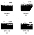
図2に、上記円板状試料において、カーボンブラックの濃度を(a)1wt%、(b)5wt%、(c)10wt%、(d)20wt%としたときの透明半円部と顔料半円部との界面の様子の観測結果を示す。観測倍率は400倍である。この観測図は、上記界面及び界面近傍における波長532nmの光の透過光の強度をモニタしたものを示す。
観測の結果、カーボンブラックの粒径は、ほぼ約0.5~2.0μmであった。ここで、カーボンブラック濃度1wt%、5wt%、10wt%の場合、カーボンブラックの粒径は、上記範囲内にほぼ全て収まり、粒径のバラつきは比較的小さいことが分かった。
他方、カーボンブラックの濃度が20wt%の場合、ほとんどのカーボンブラックの粒径は、カーボンブラック濃度1wt%、5wt%、10wt%のときと同様、ほぼ約0.5~2.0μmの範囲に収まった。しかし、ところどころ、カーボンブラックの凝集が発生していた。他の実験にて確認したところ、このカーボンブラックの凝集は、カーボンブラックの濃度が10wt%を超えたところで発生することが分かった。
すなわち、カーボンブラック濃度が1wt%、5wt%、10wt%のときは凝集が発生せず、カーボンブラックを分散させたシリコーン樹脂(ゴム)としての特性が維持できた。
カーボンブラック濃度が10wt%を超えると、カーボンブラックの凝集が始まった。しかしながら、20wt%まではカーボンブラックの粒径は、2μm以下であった。
カーボンブラック濃度が10wt%を超えると、カーボンブラックの凝集に起因し、カーボンブラックの粒径で2μmを超えるものがでてきた。さらに、上記したように、濃度が20wt%を超えると、濃度によってはPDMSの主剤とカーボンブラックがところどころ分離するようになった。
なお、シリコーン樹脂であるPDMS樹脂の硬化時間が、現状のもの(ここでは1時間)よりも短縮可能となるPDMSが開発されれば、カーボンブラック濃度が20wt%を超えてもカーボンブラックの粒径が2μm以下で、上記主剤とカーボンブラックの分離が発生しないようにすることも可能となりうる。
しかしながら、現状のPDMS樹脂の性能では、実用的なカーボンブラック濃度は、20wt%以下となる。
また、透明半円部3と顔料半円部5との界面は、カーボンブラックの濃度が10wt%、20wt%のとき、ある程度明確に画定されるようになっている。すなわち、カーボンブラック粒子が界面に沿って密集していることが確認された。
次に、カーボンブラック濃度1wt%、5wt%、10wt%、20wt%の試料における散乱光強度の角度特性を測定した。
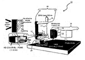
図3は、今回の測定に用いた散乱光強度の角度特性測定システム11である。図3に示すように、円板状試料1は、回転軸13を有する回転ステージ15に設置される。
回転軸13は、回転軸13から回転軸13の軸方向と直交する方向に延びる分岐部17を有する。分岐部17は、光源支持部19の支柱21に連結されている。光源支持部19は、支柱21と、支柱21から分岐された光源固定部23とからなる。光源固定部23には、波長532nmのレーザビームを放出するDPSSレーザ光源25が固定されている。
DPSSレーザ光源25から放出されるレーザビーム27は、図3に示すように、下方向に進行し、回転ステージ15の回転軸13に設けられた反射ミラー支持部29に支持された反射ミラー31により折り返され、円板状試料1に入射する。ここで、反射ミラー31は、円板状試料1の透明半円部3と顔料半円部5との境界面7に対してレーザビーム27が45度の入射角で入射するように調整されている。
円板状試料1は、上記したように、透明半円部3と顔料半円部5とからなる。ここで、両半円部を構成するシリコーン樹脂は同種の樹脂であるので、屈折率も同じである。よって、円板状試料1に入射したレーザビーム27の境界面7における界面反射は、基本的に生じない。
上記したように、レーザビーム27は境界面7にて界面反射されることなく顔料半円部5に入射する。カーボンブラックとシリコーン樹脂とは材質が異なり、屈折率が互いに異なる。そのため、このカーボンブラックに到達したレーザビーム27は、カーボンブラックにより吸収されたり、散乱されたりする。
カーボンブラックの吸収係数は、波長532nmのレーザビーム27に対して7.2×10²/cmである。そのため、カーボンブラックに到達したレーザビーム27は、カーボンブラックに強く吸収される。カーボンブラックにて吸収されなかったレーザビーム27は、当該カーボンブラックにより様々な方向に散乱される。上記散乱光のうち、顔料半円部5から透明半円部3へ進行したものは、透明半円部3から外部へと放出される。
透明半円部3から外部へとレーザビーム27が放出される側には、図3に示すように、幅2mm×上下方向の長さ30mmの開口部分を有するスリット33と、スリット33を透過する光を集光する集光レンズ35と、集光レンズ35で集光されるレーザビーム27の強度を計測するためのフォトダイオードからなるディテクタ37とを有する散乱光測定部39が設けられる。散乱光測定部39は、ディテクタ37へ入射する光をスリット33により限定している。
他方、上記したように、円板状試料1とDPSSレーザ光源25と反射ミラー31は、回転軸13と分岐部17で連結されている光源支持部19及び反射ミラー支持部29により、一体となって保持されている。よって、回転軸13を回転させても、円板状試料1へ入射するDPSSレーザ光源25らの光の入射角は維持される。
この状態で回転ステージ15の回転軸13を回転させることにより、上記入射角を維持したまま、透明半円部3から外部へと放出されるレーザビーム27の散乱光の一部が散乱光測定部39のスリット33へ導光されるように調整することが可能となる。
上記したように、スリット33は、図3に示すように、入射光の入射角を固定している。そのため、回転ステージ15の回転軸13を回転させることにより、特定の角度方向に散乱された光の強度のみ散乱光測定部39で測定することができる。すなわち、円板状試料1から放出される散乱光強度の角度特性を測定することが可能となる。
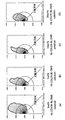
図4は、カーボンブラックの濃度が(a)1wt%、(b)5wt%、(c)10wt%、(d)20wt%の試料における散乱光強度の角度特性分布を示す図である。
図4に示す角度特性分布において、各角度方向の線分の長さは、散乱光強度を示す。よって、各線分の先端を結ぶ曲線がなす面積は、試料に入射したレーザビームの積分反射強度(散乱強度)を示す。
図4(a)~(d)から明らかなように、カーボンブラックの濃度が1wt%のときは、積分反射強度(散乱強度)が大きい。よって、透明なシリコーン樹脂からなる導光路における迷光を吸収するために、顔料(カーボンブラック)を分散させたシリコーン樹脂にてこの導光路を包囲して、導光路からの迷光を当該顔料分散シリコーン樹脂で吸収させる場合、カーボンブラックの濃度が1wt%のときは、顔料分散シリコーン樹脂からの散乱光の影響を無視できなくなるときがあると考えられる。
他方、カーボンブラックの濃度が5wt%、10wt%、20wt%の場合、積分反射強度(散乱強度)が小さい。そのため、上記迷光吸収用の顔料分散シリコーン樹脂は、十分な機能を果たせると考えられる。
カーボンブラックの濃度が1wt%のときの積分反射強度(散乱強度)が大きい理由は必ずしも明らかではないが、以下のように考えられる。カーボンブラックの濃度が1wt%の場合、各カーボンブラック粒子間の距離が大きく、多重散乱の影響が大きいものと考えられる。すなわち、1個のカーボンブラックからの散乱光が他のカーボンブラックに衝突しさらに散乱する場合、各カーボンブラック粒子間の距離が大きいので、各カーボンブラック間の空間を通過して、透明半円部3へ進行する確率が高いものと考えられる。
ここで、透明なシリコーン樹脂からなる導光路と、上記透明なシリコーン樹脂と同じ材質からなり、上記導光路からの迷光に対して吸収特性を有する顔料(カーボンブラック)が分散されたシリコーン樹脂である顔料分散シリコーン樹脂とを準備し、上記導光路を上記顔料分散シリコーン樹脂により包囲した2層構造のシリコーン樹脂からなる光学系を考える。
上記構造の光学系において、導光路を構成する透明なシリコーン樹脂と顔料分散シリコーン樹脂とが同質の材料であるので、両樹脂間の界面における光の界面反射は発生しない。よって、導光路から顔料分散シリコーン樹脂に入射する迷光は、そのまま上記顔料分散シリコーン樹脂に入射し、その大部分はカーボンブラックにより吸収される。
なお、カーボンブラックに到達したが吸収されなかった迷光は、カーボンブラック表面において散乱することとなる。その散乱光(反射光)の一部は、場合によっては、導光路に再び入射することもある。
よって、導光路からの迷光の影響を小さくするための上記2層構造のシリコーン樹脂からなる光学系は、(1)できるだけカーボンブラックにおける積分反射強度(散乱強度)が小さく、(2)できるだけカーボンブラックにおける後方散乱強度が小さい方が望ましい。
発明者らが計算したところ、カーボンブラックの粒径が2.0μmより大きくなると散乱が大きくなり、例えば2層構造のシリコーン樹脂からなる光学系における散乱条件(1)及び(2)についても実用的でなくなることが分かった。
そのため、顔料分散シリコーン樹脂におけるカーボンブラックの粒径を0.5~2.0μmとすることが好ましい。また、カーボンブラックの濃度を5~20wt%とすることが好ましい。
また、上記(1)及び(2)は、導光路を構成する透明なシリコーン樹脂と顔料分散シリコーン樹脂との界面形状により、その重要性に順列がつく。
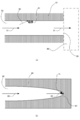
図5は、導光部の光出射側の状態の違いにより、望ましい散乱条件が異なることを示す図である。図5(a)に示すように、信号である光51が通過する導光部53の出射端55が顔料分散シリコーン樹脂57で閉じておらず開放されているとする。また、出射端55が光信号を受信するセンサ59(例えば、光強度を測定する光センサ)である場合を考える。この場合、迷光60が顔料分散シリコーン樹脂57に入射したときの顔料分散シリコーン樹脂57からの散乱光61(ノイズ光)は、できるだけ小さく、特にセンサ59に届かないことが望まれる。すなわち、(1)積分反射強度(散乱強度)が小さい方がより重要となる。
他方、図5(b)に示すように、信号である光63が通過する導光部65の出射端67が顔料分散シリコーン樹脂69により閉塞されていて、信号である光63を顔料分散シリコーン樹脂69に全て吸収させたい場合を考える。この場合、顔料分散シリコーン樹脂69からの散乱光71(ノイズ光)は、できるだけ小さく、後方に進行しないことが望まれる。すなわち、(2)後方散乱強度が小さい方がより重要となる。
なお、発明者らが先に提案した顔料を少なくとも一部に含む樹脂を用いて光学系およびモノリシックな筐体を構成した光誘起蛍光測定器(特許文献1)のように、透明なシリコーン樹脂からなる光導光部は、必ずしも透明なシリコーン樹脂で全て充填されている状態である必要はなく、空間を有していてもよい。
ここで、顔料分散シリコーン樹脂について、光学濃度(OD値)が6となるときのシリコーン樹脂の厚みを調査した。ここで光の波長は532nmとした。
カーボンブラック濃度が1wt%のとき、OD=0.3(透過率50%)となるときのシリコーン樹脂の厚みは約0.1mmであった。すなわち、透明なシリコーン樹脂からなる導光路を顔料分散シリコーン樹脂で包囲した構造の光学系を有するマイクロチップを構成する場合、カーボンブラック濃度が1wt%のときにOD=6を実現するためには、顔料分散シリコーン樹脂の厚みが1.9mm(約2mm)となる。さらに、透明シリコーン樹脂からなる導光路も導光路として機能するためにある程度の厚みが必要となる。
よって、上記マイクロチップを作製する場合、マイクロチップの上下方向の厚みを考えるとカーボンブラック濃度が1wt%のときには、透明導光路の厚み+透明導光路の上部を包囲する顔料分散シリコーン樹脂の厚み約2mm+透明導光路の下部を包囲する顔料分散シリコーン樹脂の厚み約2mmとなる。すなわち上記マイクロチップの厚みは、少なくとも透明導光路の厚み+約4mmとなり、マイクロチップとしては厚膜化してしまう。そのため、顔料分散シリコーン樹脂を作製する際、カーボンブラック濃度を1wt%以下とするのは好ましくない。
他方、カーボンブラック濃度が5wt%のとき、OD=6を実現するための顔料分散シリコーン樹脂の厚みは0.4mmとなる。よって、上記マイクロチップの上下方向の厚みは、透明導光路の厚み+0.8mmとなり、マイクロチップのサイズを実用的な大きさとすることが可能となる。よって、顔料分散シリコーン樹脂を作製する際、カーボンブラック濃度は、少なくとも5wt%以上とすることが好ましい。
以上をまとめると、シリコーン樹脂にカーボンブラックを分散させて遮光機能を有する光学部材を製造する場合、カーボンブラック濃度をCcbとすると、製造された光学部材は、Ccbに応じて以下のような特性となった。
(1)Ccb≦5wt%・・・積分反射強度(散乱強度)が大きくなり、遮光機能が乏しい。また、上記2層構造のマイクロチップを製造する場合、OD=6を実現するためには、マイクロチップの厚みが厚くなりすぎる。
(2)5wt%≦Ccb≦10wt%・・・カーボンブラックの凝集が発生せず、シリコーン樹脂(ゴム)としての特性の維持が可能。また、カーボンブラックの粒径は、0.5~2.0μmとなる。
(3)10wt%≦Ccb≦20wt%・・・カーボンブラックの凝集が発生する場合がある。また、凝集が起きてない領域のカーボンブラックの粒径は、0.5~2.0μmとなる。
(4)20wt%<Ccb・・・カーボンブラックの凝集に起因し、カーボンブラックの粒径で2μmを超えるものが出てくる。また、ある程度カーボンブラックの濃度が大きくなると、濃度によってはPDMSの主剤SIM-360とカーボンブラックが完全に分離するようになり、シリコーン樹脂にカーボンブラックを分散させることが不可能となる。
(1)Ccb≦5wt%・・・積分反射強度(散乱強度)が大きくなり、遮光機能が乏しい。また、上記2層構造のマイクロチップを製造する場合、OD=6を実現するためには、マイクロチップの厚みが厚くなりすぎる。
(2)5wt%≦Ccb≦10wt%・・・カーボンブラックの凝集が発生せず、シリコーン樹脂(ゴム)としての特性の維持が可能。また、カーボンブラックの粒径は、0.5~2.0μmとなる。
(3)10wt%≦Ccb≦20wt%・・・カーボンブラックの凝集が発生する場合がある。また、凝集が起きてない領域のカーボンブラックの粒径は、0.5~2.0μmとなる。
(4)20wt%<Ccb・・・カーボンブラックの凝集に起因し、カーボンブラックの粒径で2μmを超えるものが出てくる。また、ある程度カーボンブラックの濃度が大きくなると、濃度によってはPDMSの主剤SIM-360とカーボンブラックが完全に分離するようになり、シリコーン樹脂にカーボンブラックを分散させることが不可能となる。
すなわち、マイクロチップに使用するために、シリコーン樹脂にカーボンブラックを分散させて遮光機能を有する光学部材(本願請求項における「光学部材」及び「迷光吸収部」の一例)を製造する場合には、5wt%≦Ccb≦20wt%が好ましく、5wt%≦Ccb≦10wt%がさらに好ましい。このような光学部材を入射光を透過(導光)する導光部(本願請求項における「導光部」の一例)に隣接して用いることにより、迷光やノイズ光がセンサに入ることを抑制することが可能な光導光
部材(本願請求項における「光導光部材」の一例)を製造可能となる。
部材(本願請求項における「光導光部材」の一例)を製造可能となる。
他方、上記製造方法に基づき製造される光学部材に分散されるカーボンブラックの大きさDcbは、Dcb≦2.0μmのとき、積分反射強度(散乱強度)が小さくなり、良好な遮光性能を有することが分かった。また、Dcb>2.0μmのとき、積分反射強度が大きくなり、良好な遮光性能を実現することが難しくなることが分かった。
上記光学部材を製造するためには、硬化前のシリコーン印象材SIM-360の主剤(本願請求項における「未硬化未分散シリコーン樹脂」の一例)に所望の濃度のカーボンブラックを投入して撹拌により分散させる(本願請求項における「分散ステップ」の一例)。続いて、分散後のシリコーン樹脂(本願請求項における「未硬化分散済シリコーン樹脂」の一例)を1時間かけて硬化させて顔料分散シリコーン樹脂(本願請求項における「硬化済分散済シリコーン樹脂」の一例)を得る(本願請求項における「硬化ステップ」の一例)。
なお、ノイズ光(本願請求項における「ノイズ光」の一例)が届かない領域においては、カーボンブラックの大きさに起因して積分反射強度が大きくなっても問題ない。そのため、ノイズ光の吸収長の深さまでの領域(本願請求項における「特定の領域」及び「特定の光の吸収長の深さまでの領域」の一例)でDcb≦2.0μmであれば、好ましいマイクロチップを製造可能であるといえる。
続いて、カーボン系顔料としてカーボンナノチューブ(米国CNano社製:Flotube9000)を用い、実施例1と同様に、図1に示す円板状試料1、及び、図3の散乱光強度の角度特性測定システム11において迷光の散乱抑制性能の試験を行った。なお、性能を比較するために、カーボン系顔料としてカーボンブラック(信越シリコーン(登録商標)製:KE-COLOR-BL)も用いた。
円板状試料1として、まず、PDMSに分散させるカーボンナノチューブの濃度を変えて、3種類作製した。また、比較例としてカーボン系材料をカーボンブラックとしたものを1種類作製した。具体的には、カーボンナノチューブを用いたものについては、上記PDMSに分散させるカーボンナノチューブの濃度を0.17wt%、0.83wt%、1.7wt%とした。また、カーボンブラックを用いたものについては、上記PDMSに分散させるカーボンブラックの濃度を10wt%とした。また、PDMSの硬化時間は1時間とした。
なお、カーボンナノチューブの形状は全体的にほぼ均一であり、平均直径は10~15nmであり、平均長さは10μmであった。
一方、カーボンブラックの形状はばらつきが存在する。このカーボンブラックが分散されたPDMS樹脂を観察したところ、カーボンブラックの粒径は、ほぼ約0.5~2.0μmの範囲内にほぼ全て収まり、粒径のバラつきは比較的小さかった。
まず、カーボンナノチューブ濃度0.17wt%、0.83wt%、1.7wt%、カーボンブラック濃度10wt%の試料における散乱光強度の角度特性を測定した。
図6は、カーボンナノチューブの濃度が0.17wt%、0.83wt%、1.7wt%、カーボンブラックの濃度が10wt%の試料における散乱光強度の角度特性分布を示す図である。
図6に示す角度特性分布において、原点0から各曲線までの長さ(距離)は、散乱光強度を示す。よって、各曲線がなす面積は、試料に入射したレーザビームの積分反射強度(散乱強度)を示す。
図6から明らかなように、3種類の濃度のカーボンナノチューブを顔料として使用した場合はいずれも、カーボンブラックを顔料として使用した場合と比較すると積分反射強度(散乱強度)が小さい。
実施例1で提案しているように、透明なシリコーン樹脂からなる導光路における迷光を吸収するために、顔料(カーボンブラック)を分散させたシリコーン樹脂にてこの導光路を包囲して、導光路からの迷光を当該顔料分散シリコーン樹脂で吸収させる場合、カーボンブラックの濃度が10wt%のときは積分反射強度(散乱強度)が小さく、上記迷光吸収用の顔料分散シリコーン樹脂は、十分な機能を果たせる。
カーボンナノチューブを顔料とする場合、上記したように10wt%の濃度のカーボンブラックを用いる場合より更に散乱光強度が小さいので、カーボンナノチューブを分散した迷光吸収用のシリコーン樹脂は、カーボンブラックを使用する場合より更に良好で、十分な機能を果たせると考えられる。
顔料としてカーボンナノチューブを用いた場合の積分反射強度(散乱強度)が、カーボンブラックを用いた場合の積分反射強度(散乱強度)より顕著に小さくなる理由は必ずしも明らかではないが、以下のように考えられる。
カーボンブラックは一般的に粒子構造であるが、カーボンナノチューブは線状構造である。よって、シリコーン樹脂中に分散したカーボンナノチューブの向き(配光)と散乱光の進行方向との相対関係が、散乱の抑制効果の向上に適した関係となっているものと考えられる。
また、カーボンナノチューブの濃度が0.17wt%、0.83wt%、1.7wt%の場合について比較すると、図6から明らかなように、積分反射強度(散乱強度)は、濃度が0.83wt%のときが一番小さい。よって、カーボンナノチューブを使用した場合、積分反射強度(散乱強度)をできるだけ小さくすることが可能な最適なカーボンナノチューブ濃度は、0.17~1.7wt%の濃度範囲内に存在するものと考えられる。
上記したように、カーボンナノチューブを顔料として使用した場合はいずれも、カーボンブラックを顔料として使用した場合と比較すると積分反射強度(散乱強度)が小さいのでカーボンナノチューブを分散した迷光吸収用のシリコーン樹脂は、カーボンブラックを使用する場合より更に良好で、十分な機能を果たせると考えられる。
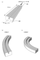
これを確認するために、図7に示すような光学系を構築し、カーボンナノチューブを分散した迷光吸収用のシリコーン樹脂とカーボンブラックを分散した迷光吸収用のシリコーン樹脂の迷光吸収特性を比較した。
図7に示すように、入射面の面積が2mm×1mm、長さ50mmの透明なPDMS樹脂からなる導光路と、この導光路を包囲するカーボン系顔料が分散された顔料分散シリコーン樹脂とからなる2層構造の光学部材を準備する。図7では、理解を容易にするために、透明なPDMS樹脂からなる導光路の上面側が剥き出しとなっているが、実際は、透明導光路の両端部以外は顔料分散シリコーン樹脂により包囲されている。
上記構造の光学系において、導光路を構成する透明なシリコーン樹脂と顔料分散シリコーン樹脂とが同質の材料であるので、両樹脂間の界面における光の界面反射は発生しない。よって、導光路から顔料分散シリコーン樹脂に入射する迷光は、そのまま上記顔料分散シリコーン樹脂に入射し、その大部分はカーボン系顔料により吸収される。
図7(a)のような光学部材において、当該光学部材のA端から、例えばビーム径が1mmである波長532nmのレーザ光を入射する。導光路の部分が透明なPDMS樹脂が充填されている構造ではなく単なる空洞であっても、レーザ光の広がりや導光路自体による吸収を無視すれば、レーザ光の一部が顔料分散PDMS樹脂にすることもないので、導光路のA端からB端までレーザビームが進行する際、レーザビームは減衰しない。
一方、図7(b)、(c)のように、45度、90度と光学部材を曲げた場合、導光路のA端から入射したレーザビームは顔料分散PDMS樹脂に衝突し、衝突したレーザビームの殆どは顔料分散PDMSに吸収されるので、レーザビームは減衰する。光学部材の曲げ角度が大きくなるほど、導光路のA端から入射したレーザビームが導光路を包囲する顔料PDMS樹脂に衝突する割合が高くなる。すなわち、B端へ到達するレーザビームの強度は小さくなる。
そこで、3つの光学部材(光学部材1、光学部材2、光学部材3)を用意し、当該光学部材の曲げ角度と入射レーザビームの減衰率との関係を調べた。3つの光学部材の構成は以下の通りである。
光学部材1は、導光路が空洞であって、顔料分散PDMSには濃度10wt%のカーボンブラックが分散している構造である。
光学部材2は、導光路が透明なPDMS樹脂が充填されている構造であって、顔料分散PDMSには濃度10wt%のカーボンブラックが分散している構造である。
光学部材3は、導光路が透明なPDMS樹脂が充填されている構造であって、顔料分散PDMSには濃度0.83wt%のカーボンナノチューブが分散している構造である。
光学部材1は、導光路が空洞であって、顔料分散PDMSには濃度10wt%のカーボンブラックが分散している構造である。
光学部材2は、導光路が透明なPDMS樹脂が充填されている構造であって、顔料分散PDMSには濃度10wt%のカーボンブラックが分散している構造である。
光学部材3は、導光路が透明なPDMS樹脂が充填されている構造であって、顔料分散PDMSには濃度0.83wt%のカーボンナノチューブが分散している構造である。
図8に、光学部材1、光学部材2、光学部材3について、光学部材の曲げ角度と入射レーザビームの減衰率との関係を示す。なお、光学部材1(空洞導光路/カーボンブラック分散樹脂)において、曲げ角度0度のときのB端におけるレーザビーム強度を100%とした。
図8に示すように、導光路が空洞であって、カーボンブラックが分散した顔料分散樹脂により上記空洞が包囲されている光学部材1の場合、曲げ角度が30度のときB端でのレーザビーム強度が10%まで減衰するが、曲げ角度が90度となってもレーザビーム強度は10%前後である。すなわち、減衰率は1/10(OD=1)のままあまり変わらない。これは、A端から入射するレーザビームにおいて、フレネル反射が大きなs偏光成分が、空洞導光路を包囲する顔料分散PDMS樹脂表面での反射によりB端まで導光されてしまうためと考えられる。
一方、導光路が透明なPDMS樹脂からなり、カーボンブラックが分散した顔料分散樹脂により上記空洞が包囲されている光学部材2の場合、曲げ角度が30度のときのレーザビーム強度は6%程度で減衰率は1/6程度(OD=1.2程度)であり、曲げ角度が60度のときのレーザビーム強度は0.005%程度で減衰率は5/1000程度(OD=2.3程度)となった。
光学部材1と比べて光学部材2のときの減衰率が良好であるのは、光学部材2においては、導光路を構成する透明なPDMS樹脂とカーボンブラック顔料分散PDMS樹脂とが同質の材料であるので、両樹脂間の界面における光の界面反射は発生しないためであると考えられる。すなわち、光学部材1のときのようなS偏光成分のフレネル反射が、光学部材2では発生しないためであると考えられる。
さらに、導光路が透明なPDMS樹脂からなり、カーボンナノチューブが分散した顔料分散樹脂により上記空洞が包囲されている光学部材3の場合、曲げ角度が30度のときに既にレーザビーム強度が0.005%程度で減衰率が1/20000程度(OD=4.3程度)となり、曲げ角度が45度のときはレーザビームを観測することができなかった。測定器の観測限界がOD=5.5程度であったので、曲げ角度が45度のときはOD=6を達成できている可能性がある。
このように、曲げ角度30度以上では、顔料分散PDMSをカーボンナノチューブとしたとき、当該顔料をカーボンブラックとしたときと比較すると飛躍的な迷光の消光効果が得られることが分かった。これは、上記したようにカーボンナノチューブの方がカーボンブラックより積分反射強度(散乱強度)が小さいので、光学部材のB端にまで到達する散乱光の強度が著しく小さいためと考えられる。
すなわち、カーボン系顔料としてカーボンナノチューブを採用し当該カーボンナノチューブが分散した樹脂部分が入射光を透過する導光部に隣接して用いた場合の迷光の散乱の抑制は、顔料がカーボンブラックのときよりも更に効果的であり、迷光の強度を更に良好に減衰させることが可能となる。
1・・・円板状試料、3・・・透明半円部、5・・・顔料半円部、7・・・境界面、11・・・角度特性測定システム、13・・・回転軸、15・・・回転ステージ、17・・・分岐部、19・・・光源支持部、21・・・支柱、23・・・光源固定部、25・・・DPSSレーザ光源、27・・・レーザビーム、29・・・反射ミラー支持部、31・・・反射ミラー、33・・・スリット、35・・・集光レンズ、37・・・ディテクタ、39・・・散乱光測定部、51・・・光、53・・・導光部、55・・・出射端、57・・・顔料分散シリコーン樹脂、59・・・センサ、60・・・迷光、61・・・散乱光、63・・・光、65・・・導光部、67・・・出射端、69・・・顔料分散シリコーン樹脂、71・・・散乱光
Claims (9)
- 入射光を透過する導光部に隣接して用いられる、前記入射光を減光する光学部材であって、
前記光学部材は、シリコーン樹脂中の特定の領域に炭素粒子を分散させた炭素粒子分散部を備え、
前記炭素粒子は、当該炭素粒子に入射して散乱する光の強度を抑制する迷光散乱抑制粒子である、光学部材。 - 前記炭素粒子分散部の前記炭素粒子には、カーボンブラック粒子が含まれており、
前記炭素粒子分散部の前記カーボンブラック粒子は、短径が2μm以下のカーボンブラック粒子のみである、請求項1記載の光学部材。 - 前記炭素粒子分散部の前記炭素粒子には、カーボンナノチューブが含まれている、請求項1又は2記載の光学部材。
- 前記特定の領域は、当該光学部材を前記導光部に隣接して用いた際に、前記導光部と当該光学部材との境界から特定の光の吸収長の深さまでの領域に相当する領域である、請求項2又は3記載の光学部材。
- 前記特定の光は、前記入射光とは異なるノイズ光である、請求項4記載の光学部材。
- 入射光を導光する光導光部材であって、
前記入射光を透過し、前記入射光に対して透明なシリコーン樹脂を少なくとも一部に有する導光部と、
前記導光部に隣接し、前記透明なシリコーン樹脂と同じ屈折率のシリコーン樹脂に炭素粒子を分散させた炭素粒子分散シリコーン樹脂を有する迷光吸収部とを備え、
前記炭素粒子は、当該炭素粒子に入射して散乱する光の強度を抑制する迷光散乱抑制粒子である、光導光部材。 - 前記炭素粒子分散部の前記炭素粒子には、カーボンブラック粒子が含まれており、
前記炭素粒子分散部の前記カーボンブラック粒子は、短径が2μm以下のカーボンブラック粒子のみである、請求項6記載の光導光部材。 - 前記炭素粒子分散部の前記炭素粒子には、カーボンナノチューブが含まれている、請求項6又は7記載の光導光部材。
- 入射光を透過する導光部に隣接して用いられる、前記入射光を減光する光学部材を生産する方法であって、
硬化前の未硬化未分散シリコーン樹脂にカーボンブラックを分散させて未硬化分散済シリコーン樹脂を形成する分散ステップと、
前記未硬化分散済シリコーン樹脂を硬化させて硬化済分散済シリコーン樹脂を形成する硬化ステップとを含み、
前記分散ステップにおいて、前記未硬化未分散シリコーン樹脂に分散させる前記カーボンブラックの濃度が、5wt%以上かつ20wt%以下である、光学部材を生産する方法。
Priority Applications (1)
| Application Number | Priority Date | Filing Date | Title |
|---|---|---|---|
| US15/576,737 US10739506B2 (en) | 2015-05-27 | 2016-04-22 | Optical member, light guiding member, and method for producing optical member |
Applications Claiming Priority (4)
| Application Number | Priority Date | Filing Date | Title |
|---|---|---|---|
| JP2015107930A JP2016224135A (ja) | 2015-05-27 | 2015-05-27 | 光学部材、光導光部材、及び、光学部材を生産する方法 |
| JP2015-107930 | 2015-05-27 | ||
| JP2015-134803 | 2015-07-03 | ||
| JP2015134803A JP6682095B2 (ja) | 2015-07-03 | 2015-07-03 | 光学部材及び光導光部材 |
Publications (1)
| Publication Number | Publication Date |
|---|---|
| WO2016190016A1 true WO2016190016A1 (ja) | 2016-12-01 |
Family
ID=57393103
Family Applications (1)
| Application Number | Title | Priority Date | Filing Date |
|---|---|---|---|
| PCT/JP2016/062774 Ceased WO2016190016A1 (ja) | 2015-05-27 | 2016-04-22 | 光学部材、光導光部材、及び、光学部材を生産する方法 |
Country Status (2)
| Country | Link |
|---|---|
| US (1) | US10739506B2 (ja) |
| WO (1) | WO2016190016A1 (ja) |
Families Citing this family (1)
| Publication number | Priority date | Publication date | Assignee | Title |
|---|---|---|---|---|
| WO2023019139A1 (en) * | 2021-08-10 | 2023-02-16 | Edmund Optics, Inc. | Optical component for redirecting light |
Citations (7)
| Publication number | Priority date | Publication date | Assignee | Title |
|---|---|---|---|---|
| JP2006337837A (ja) * | 2005-06-03 | 2006-12-14 | Shin Etsu Polymer Co Ltd | 光射出方向制御フィルム |
| JP2008102278A (ja) * | 2006-10-18 | 2008-05-01 | Shin Etsu Polymer Co Ltd | 電卓用視野角制御フィルム及び電卓 |
| JP2011186437A (ja) * | 2010-02-12 | 2011-09-22 | Canon Inc | 光学素子用の遮光膜および光学素子 |
| JP2013020118A (ja) * | 2011-07-12 | 2013-01-31 | Shin Etsu Polymer Co Ltd | 機能性遮光フィルム |
| JP2013205509A (ja) * | 2012-03-27 | 2013-10-07 | Dainippon Printing Co Ltd | 光学シート、これを備えた表示装置、および光学シートの製造方法 |
| JP2014021231A (ja) * | 2012-07-17 | 2014-02-03 | Canon Chemicals Inc | 光学素子用内面反射防止黒色塗料 |
| JP2014071229A (ja) * | 2012-09-28 | 2014-04-21 | Toshiba Tec Corp | 遮光性インク、マイクロレンズアレイユニット及び画像形成装置 |
Family Cites Families (3)
| Publication number | Priority date | Publication date | Assignee | Title |
|---|---|---|---|---|
| EP2208096B1 (en) * | 2007-10-16 | 2019-11-27 | 3M Innovative Properties Company | Higher transmission light control film |
| JP5665811B2 (ja) | 2012-08-02 | 2015-02-04 | 国立大学法人九州大学 | 光誘起蛍光測定器 |
| US9094593B2 (en) * | 2013-07-30 | 2015-07-28 | Heptagon Micro Optics Pte. Ltd. | Optoelectronic modules that have shielding to reduce light leakage or stray light, and fabrication methods for such modules |
-
2016
- 2016-04-22 US US15/576,737 patent/US10739506B2/en active Active
- 2016-04-22 WO PCT/JP2016/062774 patent/WO2016190016A1/ja not_active Ceased
Patent Citations (7)
| Publication number | Priority date | Publication date | Assignee | Title |
|---|---|---|---|---|
| JP2006337837A (ja) * | 2005-06-03 | 2006-12-14 | Shin Etsu Polymer Co Ltd | 光射出方向制御フィルム |
| JP2008102278A (ja) * | 2006-10-18 | 2008-05-01 | Shin Etsu Polymer Co Ltd | 電卓用視野角制御フィルム及び電卓 |
| JP2011186437A (ja) * | 2010-02-12 | 2011-09-22 | Canon Inc | 光学素子用の遮光膜および光学素子 |
| JP2013020118A (ja) * | 2011-07-12 | 2013-01-31 | Shin Etsu Polymer Co Ltd | 機能性遮光フィルム |
| JP2013205509A (ja) * | 2012-03-27 | 2013-10-07 | Dainippon Printing Co Ltd | 光学シート、これを備えた表示装置、および光学シートの製造方法 |
| JP2014021231A (ja) * | 2012-07-17 | 2014-02-03 | Canon Chemicals Inc | 光学素子用内面反射防止黒色塗料 |
| JP2014071229A (ja) * | 2012-09-28 | 2014-04-21 | Toshiba Tec Corp | 遮光性インク、マイクロレンズアレイユニット及び画像形成装置 |
Also Published As
| Publication number | Publication date |
|---|---|
| US10739506B2 (en) | 2020-08-11 |
| US20190011624A1 (en) | 2019-01-10 |
Similar Documents
| Publication | Publication Date | Title |
|---|---|---|
| Nashold et al. | Investigations of optical limiting mechanisms in carbon particle suspensions and fullerene solutions | |
| DE102013211854B4 (de) | Verfahren und Vorrichtung zur Bestimmung einer spektralen Änderung von gestreutem Licht | |
| DE3811475C2 (ja) | ||
| DE69816809T2 (de) | Vorrichtung für fluoreszenznachweis | |
| JP6682095B2 (ja) | 光学部材及び光導光部材 | |
| EP2361375A1 (de) | Zellaufbau für lichtstreudetektoren mit selbstfokussierenden eigenschaften | |
| EP2095071A1 (de) | Neigungssensor mit optoelektronischer libelle | |
| JP6399520B2 (ja) | 光測定装置及び光測定方法 | |
| Oelkrug et al. | Quantitative Raman spectroscopy in turbid matter: reflection or transmission mode? | |
| EP2600139A1 (de) | Kalibrierelement und Verfahren zum Kalibrieren eines Streulichtmessgeräts | |
| JP6931895B2 (ja) | 光学部材、光導光部材、及び、光学部材を生産する方法 | |
| RU2610942C1 (ru) | Способ оптического измерения счетной концентрации дисперсных частиц в жидких средах и устройство для его осуществления | |
| JP2016224135A (ja) | 光学部材、光導光部材、及び、光学部材を生産する方法 | |
| WO2019009209A1 (ja) | 光測定装置、導光部材及び光測定方法 | |
| US10739506B2 (en) | Optical member, light guiding member, and method for producing optical member | |
| AT513186B1 (de) | Kalibrierelement und Verfahren zur Herstellung eines solchen Kalibrierelements | |
| JP2015031682A (ja) | 蛍光検出器 | |
| CN102954957B (zh) | 一种拉曼光谱仪探针及其制作方法 | |
| JP2020085615A (ja) | 光学測定器 | |
| DE102014014414B4 (de) | Verfahren und Anordnung zur Wasserstoff- Sensorik | |
| JP6924439B2 (ja) | 光測定装置、導光部材及び光測定方法 | |
| JP2008249363A (ja) | 濁度計 | |
| David et al. | Fundamental review to ozone gas sensing using optical fibre sensors | |
| JP6723534B2 (ja) | 光学部材、光測定装置、試料保持部材、光測定システム及び特定波長集光部材 | |
| WO2017150369A1 (ja) | 光学系構造体、光学測定装置及び光学測定方法 |
Legal Events
| Date | Code | Title | Description |
|---|---|---|---|
| 121 | Ep: the epo has been informed by wipo that ep was designated in this application |
Ref document number: 16799724 Country of ref document: EP Kind code of ref document: A1 |
|
| NENP | Non-entry into the national phase |
Ref country code: DE |
|
| 122 | Ep: pct application non-entry in european phase |
Ref document number: 16799724 Country of ref document: EP Kind code of ref document: A1 |