WO2016189981A1 - 加工機械 - Google Patents
加工機械 Download PDFInfo
- Publication number
- WO2016189981A1 WO2016189981A1 PCT/JP2016/061390 JP2016061390W WO2016189981A1 WO 2016189981 A1 WO2016189981 A1 WO 2016189981A1 JP 2016061390 W JP2016061390 W JP 2016061390W WO 2016189981 A1 WO2016189981 A1 WO 2016189981A1
- Authority
- WO
- WIPO (PCT)
- Prior art keywords
- processing
- workpiece
- machining
- area
- additional
- Prior art date
- Legal status (The legal status is an assumption and is not a legal conclusion. Google has not performed a legal analysis and makes no representation as to the accuracy of the status listed.)
- Ceased
Links
- 0 CC*CC(C)(*C)N=O Chemical compound CC*CC(C)(*C)N=O 0.000 description 9
- BYNHJQOCCODZBE-UHFFFAOYSA-N CC1(CC2)C3C2CCCC3C1 Chemical compound CC1(CC2)C3C2CCCC3C1 BYNHJQOCCODZBE-UHFFFAOYSA-N 0.000 description 2
Images



Classifications
-
- B—PERFORMING OPERATIONS; TRANSPORTING
- B23—MACHINE TOOLS; METAL-WORKING NOT OTHERWISE PROVIDED FOR
- B23P—METAL-WORKING NOT OTHERWISE PROVIDED FOR; COMBINED OPERATIONS; UNIVERSAL MACHINE TOOLS
- B23P23/00—Machines or arrangements of machines for performing specified combinations of different metal-working operations not covered by a single other subclass
- B23P23/04—Machines or arrangements of machines for performing specified combinations of different metal-working operations not covered by a single other subclass for both machining and other metal-working operations
-
- B—PERFORMING OPERATIONS; TRANSPORTING
- B22—CASTING; POWDER METALLURGY
- B22F—WORKING METALLIC POWDER; MANUFACTURE OF ARTICLES FROM METALLIC POWDER; MAKING METALLIC POWDER; APPARATUS OR DEVICES SPECIALLY ADAPTED FOR METALLIC POWDER
- B22F10/00—Additive manufacturing of workpieces or articles from metallic powder
- B22F10/20—Direct sintering or melting
- B22F10/25—Direct deposition of metal particles, e.g. direct metal deposition [DMD] or laser engineered net shaping [LENS]
-
- B—PERFORMING OPERATIONS; TRANSPORTING
- B22—CASTING; POWDER METALLURGY
- B22F—WORKING METALLIC POWDER; MANUFACTURE OF ARTICLES FROM METALLIC POWDER; MAKING METALLIC POWDER; APPARATUS OR DEVICES SPECIALLY ADAPTED FOR METALLIC POWDER
- B22F10/00—Additive manufacturing of workpieces or articles from metallic powder
- B22F10/60—Treatment of workpieces or articles after build-up
- B22F10/66—Treatment of workpieces or articles after build-up by mechanical means
-
- B—PERFORMING OPERATIONS; TRANSPORTING
- B22—CASTING; POWDER METALLURGY
- B22F—WORKING METALLIC POWDER; MANUFACTURE OF ARTICLES FROM METALLIC POWDER; MAKING METALLIC POWDER; APPARATUS OR DEVICES SPECIALLY ADAPTED FOR METALLIC POWDER
- B22F12/00—Apparatus or devices specially adapted for additive manufacturing; Auxiliary means for additive manufacturing; Combinations of additive manufacturing apparatus or devices with other processing apparatus or devices
- B22F12/22—Driving means
-
- B—PERFORMING OPERATIONS; TRANSPORTING
- B22—CASTING; POWDER METALLURGY
- B22F—WORKING METALLIC POWDER; MANUFACTURE OF ARTICLES FROM METALLIC POWDER; MAKING METALLIC POWDER; APPARATUS OR DEVICES SPECIALLY ADAPTED FOR METALLIC POWDER
- B22F3/00—Manufacture of workpieces or articles from metallic powder characterised by the manner of compacting or sintering; Apparatus specially adapted therefor ; Presses and furnaces
- B22F3/24—After-treatment of workpieces or articles
-
- B—PERFORMING OPERATIONS; TRANSPORTING
- B23—MACHINE TOOLS; METAL-WORKING NOT OTHERWISE PROVIDED FOR
- B23K—SOLDERING OR UNSOLDERING; WELDING; CLADDING OR PLATING BY SOLDERING OR WELDING; CUTTING BY APPLYING HEAT LOCALLY, e.g. FLAME CUTTING; WORKING BY LASER BEAM
- B23K26/00—Working by laser beam, e.g. welding, cutting or boring
- B23K26/0093—Working by laser beam, e.g. welding, cutting or boring combined with mechanical machining or metal-working covered by other subclasses than B23K
-
- B—PERFORMING OPERATIONS; TRANSPORTING
- B23—MACHINE TOOLS; METAL-WORKING NOT OTHERWISE PROVIDED FOR
- B23K—SOLDERING OR UNSOLDERING; WELDING; CLADDING OR PLATING BY SOLDERING OR WELDING; CUTTING BY APPLYING HEAT LOCALLY, e.g. FLAME CUTTING; WORKING BY LASER BEAM
- B23K26/00—Working by laser beam, e.g. welding, cutting or boring
- B23K26/08—Devices involving relative movement between laser beam and workpiece
- B23K26/083—Devices involving movement of the workpiece in at least one axial direction
- B23K26/0853—Devices involving movement of the workpiece in at least two axial directions, e.g. in a plane
- B23K26/0861—Devices involving movement of the workpiece in at least two axial directions, e.g. in a plane in at least three axial directions
-
- B—PERFORMING OPERATIONS; TRANSPORTING
- B23—MACHINE TOOLS; METAL-WORKING NOT OTHERWISE PROVIDED FOR
- B23K—SOLDERING OR UNSOLDERING; WELDING; CLADDING OR PLATING BY SOLDERING OR WELDING; CUTTING BY APPLYING HEAT LOCALLY, e.g. FLAME CUTTING; WORKING BY LASER BEAM
- B23K26/00—Working by laser beam, e.g. welding, cutting or boring
- B23K26/08—Devices involving relative movement between laser beam and workpiece
- B23K26/0869—Devices involving movement of the laser head in at least one axial direction
- B23K26/0876—Devices involving movement of the laser head in at least one axial direction in at least two axial directions
- B23K26/0884—Devices involving movement of the laser head in at least one axial direction in at least two axial directions in at least three axial directions, e.g. manipulators, robots
-
- B—PERFORMING OPERATIONS; TRANSPORTING
- B23—MACHINE TOOLS; METAL-WORKING NOT OTHERWISE PROVIDED FOR
- B23K—SOLDERING OR UNSOLDERING; WELDING; CLADDING OR PLATING BY SOLDERING OR WELDING; CUTTING BY APPLYING HEAT LOCALLY, e.g. FLAME CUTTING; WORKING BY LASER BEAM
- B23K26/00—Working by laser beam, e.g. welding, cutting or boring
- B23K26/12—Working by laser beam, e.g. welding, cutting or boring in a special environment or atmosphere, e.g. in an enclosure
- B23K26/123—Working by laser beam, e.g. welding, cutting or boring in a special environment or atmosphere, e.g. in an enclosure in an atmosphere of particular gases
-
- B—PERFORMING OPERATIONS; TRANSPORTING
- B23—MACHINE TOOLS; METAL-WORKING NOT OTHERWISE PROVIDED FOR
- B23K—SOLDERING OR UNSOLDERING; WELDING; CLADDING OR PLATING BY SOLDERING OR WELDING; CUTTING BY APPLYING HEAT LOCALLY, e.g. FLAME CUTTING; WORKING BY LASER BEAM
- B23K26/00—Working by laser beam, e.g. welding, cutting or boring
- B23K26/34—Laser welding for purposes other than joining
-
- B—PERFORMING OPERATIONS; TRANSPORTING
- B23—MACHINE TOOLS; METAL-WORKING NOT OTHERWISE PROVIDED FOR
- B23K—SOLDERING OR UNSOLDERING; WELDING; CLADDING OR PLATING BY SOLDERING OR WELDING; CUTTING BY APPLYING HEAT LOCALLY, e.g. FLAME CUTTING; WORKING BY LASER BEAM
- B23K26/00—Working by laser beam, e.g. welding, cutting or boring
- B23K26/34—Laser welding for purposes other than joining
- B23K26/342—Build-up welding
-
- B—PERFORMING OPERATIONS; TRANSPORTING
- B23—MACHINE TOOLS; METAL-WORKING NOT OTHERWISE PROVIDED FOR
- B23K—SOLDERING OR UNSOLDERING; WELDING; CLADDING OR PLATING BY SOLDERING OR WELDING; CUTTING BY APPLYING HEAT LOCALLY, e.g. FLAME CUTTING; WORKING BY LASER BEAM
- B23K26/00—Working by laser beam, e.g. welding, cutting or boring
- B23K26/352—Working by laser beam, e.g. welding, cutting or boring for surface treatment
- B23K26/354—Working by laser beam, e.g. welding, cutting or boring for surface treatment by melting
-
- B—PERFORMING OPERATIONS; TRANSPORTING
- B23—MACHINE TOOLS; METAL-WORKING NOT OTHERWISE PROVIDED FOR
- B23Q—DETAILS, COMPONENTS, OR ACCESSORIES FOR MACHINE TOOLS, e.g. ARRANGEMENTS FOR COPYING OR CONTROLLING; MACHINE TOOLS IN GENERAL CHARACTERISED BY THE CONSTRUCTION OF PARTICULAR DETAILS OR COMPONENTS; COMBINATIONS OR ASSOCIATIONS OF METAL-WORKING MACHINES, NOT DIRECTED TO A PARTICULAR RESULT
- B23Q7/00—Arrangements for handling work specially combined with or arranged in, or specially adapted for use in connection with, machine tools, e.g. for conveying, loading, positioning, discharging, sorting
- B23Q7/04—Arrangements for handling work specially combined with or arranged in, or specially adapted for use in connection with, machine tools, e.g. for conveying, loading, positioning, discharging, sorting by means of grippers
-
- B—PERFORMING OPERATIONS; TRANSPORTING
- B33—ADDITIVE MANUFACTURING TECHNOLOGY
- B33Y—ADDITIVE MANUFACTURING, i.e. MANUFACTURING OF THREE-DIMENSIONAL [3D] OBJECTS BY ADDITIVE DEPOSITION, ADDITIVE AGGLOMERATION OR ADDITIVE LAYERING, e.g. BY 3D PRINTING, STEREOLITHOGRAPHY OR SELECTIVE LASER SINTERING
- B33Y30/00—Apparatus for additive manufacturing; Details thereof or accessories therefor
-
- B—PERFORMING OPERATIONS; TRANSPORTING
- B33—ADDITIVE MANUFACTURING TECHNOLOGY
- B33Y—ADDITIVE MANUFACTURING, i.e. MANUFACTURING OF THREE-DIMENSIONAL [3D] OBJECTS BY ADDITIVE DEPOSITION, ADDITIVE AGGLOMERATION OR ADDITIVE LAYERING, e.g. BY 3D PRINTING, STEREOLITHOGRAPHY OR SELECTIVE LASER SINTERING
- B33Y40/00—Auxiliary operations or equipment, e.g. for material handling
-
- B—PERFORMING OPERATIONS; TRANSPORTING
- B22—CASTING; POWDER METALLURGY
- B22F—WORKING METALLIC POWDER; MANUFACTURE OF ARTICLES FROM METALLIC POWDER; MAKING METALLIC POWDER; APPARATUS OR DEVICES SPECIALLY ADAPTED FOR METALLIC POWDER
- B22F10/00—Additive manufacturing of workpieces or articles from metallic powder
- B22F10/20—Direct sintering or melting
- B22F10/28—Powder bed fusion, e.g. selective laser melting [SLM] or electron beam melting [EBM]
-
- B—PERFORMING OPERATIONS; TRANSPORTING
- B22—CASTING; POWDER METALLURGY
- B22F—WORKING METALLIC POWDER; MANUFACTURE OF ARTICLES FROM METALLIC POWDER; MAKING METALLIC POWDER; APPARATUS OR DEVICES SPECIALLY ADAPTED FOR METALLIC POWDER
- B22F12/00—Apparatus or devices specially adapted for additive manufacturing; Auxiliary means for additive manufacturing; Combinations of additive manufacturing apparatus or devices with other processing apparatus or devices
- B22F12/80—Plants, production lines or modules
- B22F12/82—Combination of additive manufacturing apparatus or devices with other processing apparatus or devices
- B22F12/86—Serial processing with multiple devices grouped
-
- B—PERFORMING OPERATIONS; TRANSPORTING
- B22—CASTING; POWDER METALLURGY
- B22F—WORKING METALLIC POWDER; MANUFACTURE OF ARTICLES FROM METALLIC POWDER; MAKING METALLIC POWDER; APPARATUS OR DEVICES SPECIALLY ADAPTED FOR METALLIC POWDER
- B22F2999/00—Aspects linked to processes or compositions used in powder metallurgy
-
- B—PERFORMING OPERATIONS; TRANSPORTING
- B33—ADDITIVE MANUFACTURING TECHNOLOGY
- B33Y—ADDITIVE MANUFACTURING, i.e. MANUFACTURING OF THREE-DIMENSIONAL [3D] OBJECTS BY ADDITIVE DEPOSITION, ADDITIVE AGGLOMERATION OR ADDITIVE LAYERING, e.g. BY 3D PRINTING, STEREOLITHOGRAPHY OR SELECTIVE LASER SINTERING
- B33Y10/00—Processes of additive manufacturing
-
- C—CHEMISTRY; METALLURGY
- C04—CEMENTS; CONCRETE; ARTIFICIAL STONE; CERAMICS; REFRACTORIES
- C04B—LIME, MAGNESIA; SLAG; CEMENTS; COMPOSITIONS THEREOF, e.g. MORTARS, CONCRETE OR LIKE BUILDING MATERIALS; ARTIFICIAL STONE; CERAMICS; REFRACTORIES; TREATMENT OF NATURAL STONE
- C04B2235/00—Aspects relating to ceramic starting mixtures or sintered ceramic products
- C04B2235/60—Aspects relating to the preparation, properties or mechanical treatment of green bodies or pre-forms
- C04B2235/602—Making the green bodies or pre-forms by moulding
- C04B2235/6026—Computer aided shaping, e.g. rapid prototyping
-
- Y—GENERAL TAGGING OF NEW TECHNOLOGICAL DEVELOPMENTS; GENERAL TAGGING OF CROSS-SECTIONAL TECHNOLOGIES SPANNING OVER SEVERAL SECTIONS OF THE IPC; TECHNICAL SUBJECTS COVERED BY FORMER USPC CROSS-REFERENCE ART COLLECTIONS [XRACs] AND DIGESTS
- Y02—TECHNOLOGIES OR APPLICATIONS FOR MITIGATION OR ADAPTATION AGAINST CLIMATE CHANGE
- Y02P—CLIMATE CHANGE MITIGATION TECHNOLOGIES IN THE PRODUCTION OR PROCESSING OF GOODS
- Y02P10/00—Technologies related to metal processing
- Y02P10/25—Process efficiency
Definitions
- the present invention generally relates to a processing machine, and more particularly to a processing machine capable of removing and adding a workpiece.
- Japanese Patent Application Laid-Open No. 2004-314168 discloses a laser cladding apparatus for pump equipment intended to quickly and accurately overlay a base material without causing cracks.
- Patent Document 1 The laser cladding apparatus disclosed in Patent Document 1 includes a powder feeder that supplies a metal material (powder) using argon gas as a carrier gas, and uniformly mixes the supplied metal material with argon gas, and at the same time as a shield gas.
- JP 2012-206137 A discloses a repair device for the purpose of easy overlay welding without human intervention (Patent Document 2).
- the repair device disclosed in Patent Document 2 includes a material supply unit, a laser device that emits laser spot light, and a welding robot that has a multi-joint arm and moves the laser spot light in a three-dimensional direction.
- an object of the present invention is to solve the above-described problems, and to provide a processing machine capable of removing and adding a workpiece with a simple configuration.
- the processing machine is a processing machine capable of workpiece removal processing and additional processing.
- the processing machine is provided in a first processing area and holds a workpiece holding part, a tool holding part that is provided in the first processing area and holds a tool for workpiece removal processing, and a second processing area.
- An additional machining head provided and a manipulator that holds the workpiece and conveys the workpiece between the first machining area and the second machining area.
- the additional processing head discharges the material to the work held by the manipulator during the additional processing of the work.
- FIG. 1 It is a front view which shows the processing machine in Embodiment 1 of this invention. It is a perspective view which shows the robot arm with which the processing machine in FIG. 1 is provided. It is sectional drawing which expands and shows the workpiece
- FIG. 1 is a front view showing a processing machine according to Embodiment 1 of the present invention.
- the inside of the processing machine is shown by seeing through the cover body that forms the appearance of the processing machine.
- a processing machine 100 is an AM / SM hybrid processing machine capable of workpiece addition processing (AM (Additive manufacturing) processing) and workpiece removal processing (SM (Subtractive manufacturing) processing).
- the processing machine 100 has a turning function using a fixed tool and a milling function using a rotating tool as SM processing functions.
- the processing machine 100 includes a bed 141, a first spindle stock 111, a second spindle stock 116, a tool spindle 121 and a lower tool rest 131 for workpiece removal processing, and an additional machining head 61 for workpiece machining. And have.
- the bed 141 is a base member for supporting the first spindle stock 111, the second spindle stock 116, the tool spindle 121, the lower tool post 131, and the additional processing head 61, and is installed on an installation surface such as a factory. .
- the first spindle stock 111, the second spindle stock 116, the tool spindle 121, and the lower tool rest 131 are provided in the first machining area 200.
- the additional processing head 61 is provided in the second processing area 210.
- the first machining area 200 and the second machining area 210 are provided adjacent to each other in the Z-axis direction extending in the horizontal direction.
- the first head stock 111 and the second head stock 116 are provided to face each other in the Z-axis direction.
- the first spindle stock 111 and the second spindle stock 116 have a first spindle 112 and a second spindle 117 for rotating the workpiece during turning using a fixed tool, respectively.
- the first main shaft 112 is provided to be rotatable around a central axis 201 parallel to the Z axis
- the second main shaft 117 is provided to be rotatable about a central axis 202 parallel to the Z axis.
- the first main shaft 112 and the second main shaft 117 are provided with a chuck mechanism for detachably holding the workpiece.
- the second head stock 116 is provided to be movable in the Z-axis direction by various feed mechanisms, guide mechanisms, servo motors, and the like.
- the tool spindle (upper tool post) 121 rotates the rotary tool during milling using the rotary tool.
- the tool spindle 121 is provided to be rotatable around a central axis 203 parallel to the X axis extending in the vertical direction.
- the tool spindle 121 is provided with a clamp mechanism for detachably holding the rotary tool.
- the tool spindle 121 is supported on the bed 141 by a column or the like (not shown).
- the tool spindle 121 extends in the X-axis direction, the horizontal direction, and can be moved in the Y-axis direction and the Z-axis direction orthogonal to the Z-axis direction by various feed mechanisms, guide mechanisms, servo motors, and the like provided in the column. Is provided.
- the machining position by the rotary tool mounted on the tool spindle 121 moves three-dimensionally.
- the tool spindle 121 is further provided so as to be pivotable about a central axis parallel to the Y axis.
- the additional processing head 61 performs additional processing by discharging material powder onto the workpiece and irradiating the workpiece with laser light (Directed Energy Deposition).
- the additional processing head 61 has a main body portion 62 and a laser beam emitting portion 65.
- the main body portion 62 incorporates a collimation lens, a reflecting mirror, and the like, and guides laser light introduced from the outside toward the laser light emitting portion 65.
- An opening 66 is formed in the laser light emitting portion 65, laser light is emitted through the opening 66, and material powder is discharged.
- the additional processing head 61 is provided so as to be movable in the X-axis direction by various feed mechanisms, guide mechanisms, servo motors, and the like.
- the additional processing head 61 is not limited to such a configuration.
- the additional processing head 61 may be fixedly provided in the second processing area 210 or may be provided to be movable in an axial direction other than the X axis.
- the additional processing head 61 may include a turning mechanism, and may be provided so as to be turnable about a central axis parallel to the Y axis, for example.
- the processing machine 100 further includes a material powder supply device 70, a laser oscillation device 76, and a tube member 73.
- the material powder supply device 70 supplies the material powder used for the additional processing toward the additional processing head 61.
- the material powder supply apparatus 70 includes a material powder tank 72 that stores material powder used for additional processing, and a mixing unit 71 that mixes material powder and carrier gas.
- the laser oscillation device 76 oscillates a laser beam used for additional processing.
- the tube member 73 is routed from the material powder supply device 70 and the laser oscillation device 76 to the additional processing head 61.
- An optical fiber for guiding the laser beam from the laser oscillation device 76 toward the additional processing head 61 and the material powder supplied from the material powder supply device 70 are directed to the additional processing head 61.
- a pipe for guiding is accommodated.
- the processing machine 100 further includes an inert gas tank 81 and a pipe 82 as an inert gas supply unit that supplies an inert gas to the second processing area 210.
- the inert gas tank 81 stores an inert gas such as argon or nitrogen.
- the pipe 82 is routed from the inert gas tank 81 toward the second processing area 210.
- the inert gas stored in the inert gas tank 81 is supplied to the second processing area 210 through the pipe 82.
- an oxygen concentration detection sensor 86 for detecting the oxygen concentration in the area is provided.
- the processing machine 100 has a cover body 142.
- the cover body 142 defines each area of the first processing area 200 and the second processing area 210.
- the cover body 142 is configured by combining a plurality of sheet metals and seal members.
- the cover body 142 includes a partition wall 143 that separates the first processing area 200 and the second processing area 210.
- the partition wall 143 is provided on the opposite side of the first spindle stock 111 with respect to the second spindle stock 116.
- the partition wall 143 is provided with a shutter 144 that can be opened and closed in order to enable movement of a robot arm 31 described later.
- the cover body 142 is provided so that the second processing area 210 is a substantially sealed space.
- the sealing degree of the second processing area 210 by the cover body 142 is higher than the sealing degree of the first processing area 200 by the cover body 142.
- the leakage of the inert gas from the second processing area 210 or the inflow of outside air containing oxygen to the second processing area 210 is suppressed, and the second processing area is added during the workpiece additional processing.
- 210 can be an inert gas atmosphere more reliably.
- the first machining area 200 where the removal process is performed needs to discharge chips and cutting oil to the outside of the machine, and thus it is difficult to make the space highly sealed.
- the second process area 210 can be a highly sealed space.
- FIG. 2 is a perspective view showing a robot arm provided in the processing machine in FIG. With reference to FIGS. 1 and 2, the processing machine 100 further includes a robot arm 31.
- the robot arm 31 holds a workpiece and conveys the workpiece between the first machining area 200 and the second machining area 210.
- the robot arm 31 includes a moving mechanism unit 21, a base unit 32 supported by the moving mechanism unit 21, an arm unit 33 rotatably connected to the base unit 21, and a workpiece gripping unit 51 that detachably grips a workpiece. And a robot arm that can control six axes independently of each other.
- the moving mechanism unit 21 is configured to be movable between the first processing area 200 and the second processing area 210.
- the moving mechanism unit 21 includes a base member 23, a linear guide 22, a rack and pinion 25, and a servo motor (not shown) as a mechanism for moving the robot arm 31 back and forth linearly.
- the robot arm 31 capable of 6-axis control has been described, but a robot arm capable of multi-axis control other than 6 axes may be used.
- the robot arm 31 includes the linear motion mechanism (moving mechanism unit 21).
- the robot arm 31 is linearly movable.
- a robot arm without a mechanism may be used.
- the robot arm may be configured to be rotatable about a rotation axis parallel to the X axis.
- the robot arm may be configured to include only a linear motion mechanism having a plurality of axes (typically, three axes).
- the processing machine 100 may further include a work stocker unit that can store a work.
- the robot arm may be configured to transfer the workpiece between the removal processing position, the additional processing position, and the work stocker unit.
- FIG. 3 is a cross-sectional view showing an enlarged work surface during additional machining.
- the additional processing head 61 discharges material to the workpiece gripped by the robot arm 31 during additional processing of the workpiece.
- the workpiece 41 is gripped by the workpiece gripping portion 51 during additional machining of the workpiece.
- the gripped work 41 is brought close to the additional processing head 61.
- the additional processing head 61 and the work 41 are relatively moved while the opening surface of the opening 66 faces the surface of the work 41.
- the laser beam 311, the material powder 312, and the shield and carrier gas 313 are discharged from the opening 66 of the additional processing head 61 toward the workpiece 41.
- a melting point 314 is formed on the surface of the workpiece 41, and as a result, the material powder 312 is welded.
- the overlay layer 316 is formed on the surface of the work 41.
- a build-up material 315 is placed on the build-up layer 316.
- a workable layer is formed on the surface of the workpiece 41.
- an electron beam may be used instead of the laser beam 311.
- metal powder such as aluminum alloy and magnesium alloy, or ceramic powder can be used.
- the processing machine 100 capable of removing and adding a workpiece can be configured simply.
- the processing machine 100 in this Embodiment is a processing machine in which the removal process of a workpiece
- the processing machine 100 is provided in a first machining area 200, and is provided in a first spindle stock 111 and a second spindle stock 116 as workpiece holding parts for holding a workpiece, and in the first machining area 200, and is used for workpiece removal machining.
- the additional processing head 61 discharges material to the work held by the robot arm 31 during the additional processing of the work.
- processing machine 100 configured as described above, it is possible to realize a processing machine capable of workpiece removal processing and additional processing with a simple configuration.
- an AM / SM hybrid processing machine is configured based on the combined processing machine having the turning function and the milling function.
- the present invention is not limited to such a configuration, and a lathe having a turning function.
- an AM / SM hybrid processing machine may be configured based on a machining center having a milling function.
- a table is used as a work holding unit that holds a work in the first processing area.
- the additional processing executed by the processing machine 100 is not limited to the directional energy deposition method.
- a material extrusion method in which a molten thermoplastic resin is laminated on a workpiece to create a three-dimensional shape, or the surface of a powder bed It may be a powder bed fusion bonding method in which the vicinity is selectively melted and solidified by heat and laminated.
- FIG. 4 is a diagram showing a form of a workpiece that changes with addition processing and removal processing.
- a base material 42 is prepared.
- the base material 42 has a disk shape.
- the intermediate workpiece 46 in which the built-up portion 43 is formed on the end surface of the base material 42 is obtained by additional processing.
- the built-up portion 43 has a cylindrical shape.
- the screw portion 44 is formed on the outer peripheral surface of the built-up portion 43 by removal processing.
- a final product 47 in which the screw portion 44 is formed is obtained.
- 5 to 10 are diagrams schematically showing the steps of the workpiece machining method according to the second embodiment of the present invention.
- the base material 42 is gripped by the work gripping portion 51 in the second processing area 210.
- the gripped work 41 is brought close to the additional processing head 61. While depositing material powder from the additional processing head 61 toward the base material 42, irradiation with a laser beam forms the built-up portion 43 on the base material 42 (manufacture of the intermediate workpiece 46).
- the robot arm 31 is moved from the second processing area 210 to the first processing area 200.
- the held intermediate workpiece 46 is brought close to the second head stock 116.
- the built-up portion 43 is positioned at a predetermined position with respect to the second main shaft 117, the built-up portion 43 is chucked by the second main shaft 117.
- the gripping of the base material 42 by the work gripping part 51 is released.
- the robot arm 31 is retracted from the first processing area 200 to the second processing area 210.
- the first head stock 111 and the second head stock 116 are brought close to each other. While the base material 42 is chucked by the first spindle 112 and the chucking of the built-up portion 43 by the second spindle 117 is released, the intermediate workpiece 46 is transferred from the second spindle stock 116 to the first spindle stock 111. Change. On the other hand, in the second machining area 210, a new base material 42 is gripped by the workpiece gripping portion 51.
- the removal processing in the first processing area 200 and the additional processing in the second processing area 210 can proceed simultaneously. Further, at the time of removal processing, the first processing area 200 is placed in an atmosphere of cutting oil. In the present embodiment, since the additional processing head 61 is in the second processing area 210 during the removal processing, it is possible to prevent the additional processing head 61 including an optical component from being exposed to the cutting oil.
- the first main spindle 111 and the second main spindle 116 are brought close to each other while synchronizing the rotations of the first main spindle 112 and the second main spindle 117.
- the end of the built-up portion 43 of the intermediate workpiece 46 is chucked by the second main shaft 117.
- removal processing parting-off processing for separating the base material 42 and the built-up portion 43 is performed.
- the base material 42 remains on the first head stock 111 and the final product 47 remains on the second head stock 116. From the first processing area 200, the base material 42 and the final product 47 are collected.
- FIG. 11 is a front view schematically showing a processing machine according to Embodiment 3 of the present invention.
- the processing machine in the present embodiment basically has the same structure as the processing machine 100 in the first embodiment.
- the description of the overlapping structure will not be repeated.
- moving mechanism unit 21 of robot arm 31 has a carriage unit 411 and a rail 412.
- the rail 412 extends linearly between the first processing area 200 and the second processing area 210.
- the rail 412 is provided at the bottom of the first processing area 200 and the second processing area 210.
- the carriage unit 411 is provided so as to be able to travel on the rail 412.
- the base portion 32 has a shape protruding vertically upward from the moving mechanism portion 21 (cart unit 411).
- the structure of the arm part 33 extending in an arm shape from the base part 32 is the same as that of the processing machine 100 in the first embodiment.
- the shutter 144 is provided at a position close to the bottom of the first processing area 200 and the second processing area 210 according to the height at which the robot arm 31 moves.
- the processing machine is a processing machine capable of workpiece removal processing and additional processing.
- the processing machine is provided in a first processing area and holds a workpiece holding part, a tool holding part that is provided in the first processing area and holds a tool for workpiece removal processing, and a second processing area.
- An additional machining head provided and a manipulator that holds the workpiece and conveys the workpiece between the first machining area and the second machining area.
- the additional processing head discharges the material to the work held by the manipulator during the additional processing of the work.
- a mechanism for holding the workpiece in the second processing area is provided in order to discharge the material to the workpiece held by the workpiece transfer manipulator during the workpiece additional machining. There is no need to provide it separately. For this reason, it is possible to realize a processing machine capable of workpiece removal processing and additional processing with a simple configuration.
- the processing machine includes an inert gas supply unit that supplies an inert gas to the second processing area, and a partition that separates the first processing area and the second processing area, and the second processing area is substantially sealed. And a cover body formed in the formed space.
- the second processing area by suppressing leakage of the inert gas from the second processing area, the second processing area can be more surely set to the inert gas atmosphere during the additional processing of the workpiece. Can do.
- the manipulator is a robot arm that has a moving mechanism that can move between the first machining area and the second machining area and is capable of multi-axis control.
- the relative positional relationship between the workpiece held by the robot arm and the additional processing head can be freely changed during additional processing of the workpiece.
- the present invention is mainly applied to an AM / SM hybrid processing machine capable of workpiece removal processing and additional processing.
Landscapes
- Engineering & Computer Science (AREA)
- Physics & Mathematics (AREA)
- Optics & Photonics (AREA)
- Mechanical Engineering (AREA)
- Manufacturing & Machinery (AREA)
- Plasma & Fusion (AREA)
- Chemical & Material Sciences (AREA)
- Materials Engineering (AREA)
- Robotics (AREA)
- Powder Metallurgy (AREA)
- Laser Beam Processing (AREA)
- Feeding Of Workpieces (AREA)
Abstract
加工機械(100)は、ワークの除去加工および付加加工が可能な加工機械である。加工機械(100)は、第1加工エリア(200)に設けられ、ワークを保持する第1主軸台(111)および第2主軸台(116)と、第1加工エリア(200)に設けられ、ワークの除去加工のための工具を保持する下刃物台(131)および工具主軸(121)と、第2加工エリア(210)に設けられる付加加工用ヘッド(61)と、ワークを保持し、第1加工エリア(200)および第2加工エリア(210)の間でワークを搬送するロボットアーム(31)とを備える。付加加工用ヘッド(61)は、ワークの付加加工時に、ロボットアーム(31)により保持されたワークに対して材料を吐出する。このような構成により、簡易な構成で、ワークの除去加工および付加加工が可能な加工機械を提供する。
Description
この発明は、一般的には、加工機械に関し、より特定的には、ワークの除去加工および付加加工が可能な加工機械に関する。
従来の加工機械に関して、たとえば、特開2004-314168号公報には、母材に割れを発生させることなく、迅速かつ正確に肉盛することを目的とした、ポンプ機器類のレーザ肉盛装置が開示されている(特許文献1)。特許文献1に開示されたレーザ肉盛装置は、アルゴンガスをキャリアガスとして金属材料(粉末)を供給する粉末供給機と、供給された金属材料をアルゴンガスと均一に混合し、同時にシールドガスとしてアルゴンおよび窒素の混合ガスを用いる過流式粉末供給ノズルと、過流式粉末供給ノズルを移動させる多軸ロボットとを有する。
また、特開2012-206137号公報には、人手を介さずに容易に肉盛溶接することを目的とした、補修装置が開示されている(特許文献2)。特許文献2に開示された補修装置は、材料供給部と、レーザスポット光を照射するレーザ装置と、多関節のアームを有し、レーザスポット光を3次元方向に移動させる溶接ロボットとを有する。
材料を付着することによってワークに3次元形状を作成するものとして、付加加工法(Additive manufacturing)がある。他方、材料を除去することによってワークに3次元形状を作成するものとして、除去加工法(Subtractive manufacturing)がある。付加加工では、加工前後でワークの質量が増加し、除去加工では、加工前後でワークの質量が減少する。それぞれの加工法の特性を生かして、付加加工および除去加工を組み合わせ、ワークの最終的な形状を得る加工が行われる。
一方、上述の特許文献には、付加加工のための各種の加工機械が開示されている。しかしながら、除去加工のための工作機械と、付加加工のための加工機械とをそれぞれ独立して設けると、設備費用が高コストとなる。このため、簡易な構成で、ワークの除去加工および付加加工が可能な加工機械を実現することが求められる。
そこでこの発明の目的は、上記の課題を解決することであり、簡易な構成で、ワークの除去加工および付加加工が可能な加工機械を提供することである。
この発明に従った加工機械は、ワークの除去加工および付加加工が可能な加工機械である。加工機械は、第1加工エリアに設けられ、ワークを保持するワーク保持部と、第1加工エリアに設けられ、ワークの除去加工のための工具を保持する工具保持部と、第2加工エリアに設けられる付加加工用ヘッドと、ワークを保持し、第1加工エリアおよび第2加工エリアの間でワークを搬送するマニピュレータとを備える。付加加工用ヘッドは、ワークの付加加工時に、マニピュレータにより保持されたワークに対して材料を吐出する。
この発明に従えば、簡易な構成で、ワークの除去加工および付加加工が可能な加工機械を提供することができる。
この発明の実施の形態について、図面を参照して説明する。なお、以下で参照する図面では、同一またはそれに相当する部材には、同じ番号が付されている。
(実施の形態1)
図1は、この発明の実施の形態1における加工機械を示す正面図である。図1中には、加工機械の外観をなすカバー体を透視することにより、加工機械の内部が示されている。
図1は、この発明の実施の形態1における加工機械を示す正面図である。図1中には、加工機械の外観をなすカバー体を透視することにより、加工機械の内部が示されている。
図1を参照して、加工機械100は、ワークの付加加工(AM(Additive manufacturing)加工)と、ワークの除去加工(SM(Subtractive manufacturing)加工)とが可能なAM/SMハイブリッド加工機である。加工機械100は、SM加工の機能として、固定工具を用いた旋削機能と、回転工具を用いたミーリング機能とを有する。
加工機械100は、ベッド141と、ワークの除去加工のための第1主軸台111、第2主軸台116、工具主軸121および下刃物台131と、ワークの付加加工のための付加加工用ヘッド61とを有する。
ベッド141は、第1主軸台111、第2主軸台116、工具主軸121、下刃物台131および付加加工用ヘッド61を支持するためのベース部材であり、工場などの据付け面に設置されている。
第1主軸台111、第2主軸台116、工具主軸121および下刃物台131は、第1加工エリア200に設けられている。付加加工用ヘッド61は、第2加工エリア210に設けられている。第1加工エリア200および第2加工エリア210は、水平方向に延びるZ軸方向において、互いに隣り合って設けられている。
第1主軸台111および第2主軸台116は、Z軸方向において、互いに対向して設けられている。第1主軸台111および第2主軸台116は、それぞれ、固定工具を用いた旋削加工時にワークを回転させるための第1主軸112および第2主軸117を有する。第1主軸112は、Z軸に平行な中心軸201を中心に回転可能に設けられ、第2主軸117は、Z軸に平行な中心軸202を中心に回転可能に設けられている。第1主軸112および第2主軸117には、ワークを着脱可能に保持するためのチャック機構が設けられている。
第2主軸台116は、各種の送り機構や案内機構、サーボモータなどにより、Z軸方向に移動可能に設けられている。
工具主軸(上刃物台)121は、回転工具を用いたミーリング加工時に回転工具を回転させる。工具主軸121は、鉛直方向に延びるX軸に平行な中心軸203を中心に回転可能に設けられている。工具主軸121には、回転工具を着脱可能に保持するためのクランプ機構が設けられている。
工具主軸121は、図示しないコラム等によりベッド141上に支持されている。工具主軸121は、コラム等に設けられた各種の送り機構や案内機構、サーボモータなどにより、X軸方向、水平方向に延び、Z軸方向に直交するY軸方向、およびZ軸方向に移動可能に設けられている。工具主軸121に装着された回転工具による加工位置は、3次元的に移動する。工具主軸121は、さらに、Y軸に平行な中心軸を中心に旋回可能に設けられている。
付加加工用ヘッド61は、ワークに対して材料粉末を吐出するとともにレーザ光を照射することにより付加加工を行なう(指向性エネルギ堆積法(Directed Energy Deposition))。
付加加工用ヘッド61は、本体部62およびレーザ光出射部65を有する。本体部62には、コリメーションレンズや反射鏡等が内蔵されており、外部から導入されたレーザ光をレーザ光出射部65に向けて導く。レーザ光出射部65には、開口部66が形成されており、その開口部66を通じてレーザ光が出射され、材料粉末が吐出される。
付加加工用ヘッド61は、各種の送り機構や案内機構、サーボモータなどにより、X軸方向に移動可能に設けられている。付加加工用ヘッド61は、このような構成に限られず、たとえば、第2加工エリア210内に固定して設けられてもよいし、X軸以外の軸方向に移動可能に設けられてもよい。付加加工用ヘッド61は、旋回機構を備えてもよく、たとえば、Y軸に平行な中心軸を中心に旋回可能に設けられてもよい。
加工機械100は、材料粉末供給装置70、レーザ発振装置76および管部材73をさらに有する。材料粉末供給装置70は、付加加工に用いられる材料粉末を付加加工用ヘッド61に向けて供給する。材料粉末供給装置70は、付加加工に用いられる材料粉末を貯留する材料粉末タンク72と、材料粉末とキャリアガスとを混合する混合部71とを有する。
レーザ発振装置76は、付加加工に用いられるレーザ光を発振する。管部材73は、材料粉末供給装置70およびレーザ発振装置76から付加加工用ヘッド61まで配索されている。管部材73には、レーザ発振装置76からのレーザ光を付加加工用ヘッド61に向けて導くための光ファイバと、材料粉末供給装置70より供給された材料粉末を付加加工用ヘッド61に向けて導くための配管とが収容されている。
ワークに材料粉末を吐出することにより付加加工を行なう指向性エネルギ堆積法においては、加工エリアを不活性ガス雰囲気にすることが求められる。そこで、加工機械100は、第2加工エリア210に不活性ガスを供給する不活性ガス供給部として、不活性ガスタンク81および配管82をさらに有する。
不活性ガスタンク81は、アルゴンや窒素等の不活性ガスを貯える。配管82は、不活性ガスタンク81から第2加工エリア210に向けて配索されている。不活性ガスタンク81に貯えられた不活性ガスは、配管82を通じて第2加工エリア210に供給される。第2加工エリア210には、エリア内の酸素濃度を検出するための酸素濃度検出センサ86が設けられている。
加工機械100は、カバー体142を有する。カバー体142は、第1加工エリア200および第2加工エリア210の各エリアを区画形成する。カバー体142は、複数枚の板金やシール部材が組み合わさって構成されている。
カバー体142は、第1加工エリア200および第2加工エリア210を隔てる隔壁部143を有する。隔壁部143は、第2主軸台116に対して第1主軸台111の反対側に設けられている。隔壁部143には、後述するロボットアーム31の移動を可能とするために、開閉可能なシャッタ144が設けられている。
カバー体142は、第2加工エリア210を略密閉された空間とするように設けられている。カバー体142による第2加工エリア210の密閉度は、カバー体142による第1加工エリア200の密閉度よりも高い。
このような構成によれば、第2加工エリア210からの不活性ガスの漏洩、または、第2加工エリア210への酸素を含む外気の流入を抑制し、ワークの付加加工時、第2加工エリア210をより確実に不活性ガス雰囲気とすることができる。除去加工を行なう第1加工エリア200は、切粉や切削油を機外に排出する必要があるため、密閉度の高い空間にすることが難しい。本実施の形態では、除去加工および付加加工を隔壁部143により隔てられた別々の加工エリアで行なうため、第2加工エリア210を密閉度の高い空間にすることが可能である。
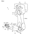
図2は、図1中の加工機械が備えるロボットアームを示す斜視図である。図1および図2を参照して、加工機械100は、ロボットアーム31をさらに有する。ロボットアーム31は、ワークを保持し、第1加工エリア200および第2加工エリア210の間でワークを搬送する。
ロボットアーム31は、移動機構部21と、移動機構部21に支持される基部32と、基部21に回動可能に連結されるアーム部33と、ワークを着脱可能に把持するワーク把持部51とを有し、6軸を互いに独立して制御可能なロボットアームである。
移動機構部21は、第1加工エリア200および第2加工エリア210の間で移動可能なように構成されている。移動機構部21は、ロボットアーム31を直線往復移動させるための機構として、ベース部材23、リニアガイド22、ラックピニオン25およびサーボモータ(不図示)を有する。
なお、本実施の形態では、6軸制御可能なロボットアーム31について説明したが、6軸以外の多軸制御可能なロボットアームであってもよい。また、本実施の形態では、ロボットアーム31が直動機構(移動機構部21)を備えるが、第1加工エリア200および第2加工エリア210の間でワークの搬送が可能であれば、直動機構を備えないロボットアームであってもよい。たとえば、ロボットアームを、X軸に平行な回転軸を中心に旋回可能な構成としてもよい。また、ロボットアームを、複数軸(代表的には、3軸)の直動機構のみを備える構成としてもよい。
加工機械100は、ワークを格納可能なワークストッカ部をさらに有してもよい。この場合に、ロボットアームを、除去加工位置、付加加工位置およびワークストッカ部の間でワークを搬送する構成としてもよい。
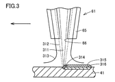
図3は、付加加工時のワーク表面を拡大して示す断面図である。図1から図3を参照して、付加加工用ヘッド61は、ワークの付加加工時に、ロボットアーム31により把持されたワークに対して材料を吐出する。
より具体的に説明すると、ワークの付加加工時、ワーク把持部51によりワーク41を把持する。ロボットアーム31を動作させることによって、把持したワーク41を付加加工用ヘッド61に接近させる。ロボットアーム31の動作および/または付加加工用ヘッド61の移動によって、開口部66の開口面をワーク41の表面に対面させたまま、付加加工用ヘッド61およびワーク41を相対的に移動させる。このとき、付加加工用ヘッド61の開口部66からワーク41に向けて、レーザ光311と、材料粉末312と、シールドおよびキャリア用のガス313とが吐出される。これにより、ワーク41の表面に溶融点314が形成され、その結果、材料粉末312が溶着する。
具体的には、ワーク41の表面に肉盛層316が形成される。肉盛層316上には、肉盛素材315が盛られる。肉盛素材315が冷却されると、ワーク41の表面に加工可能な層が形成された状態となる。なお、レーザ光311に替えて、電子ビームが用いられてもよい。材料粉末としては、アルミニウム合金およびマグネシウム合金等の金属粉末や、セラミック粉末を利用することができる。
このような構成によれば、ワークの付加加工時、ワーク搬送用のロボットアーム31によりワークを把持するため、第2加工エリア210にワークを保持するための機構を別途設ける必要がない。このため、ワークの除去加工および付加加工が可能な加工機械100を簡易な構成とすることができる。
以上に説明した、この発明の実施の形態1における加工機械100の構造についてまとめて説明すると、本実施の形態における加工機械100は、ワークの除去加工および付加加工が可能な加工機械である。加工機械100は、第1加工エリア200に設けられ、ワークを保持するワーク保持部としての第1主軸台111および第2主軸台116と、第1加工エリア200に設けられ、ワークの除去加工のための工具を保持する工具保持部としての下刃物台131および工具主軸121と、第2加工エリア210に設けられる付加加工用ヘッド61と、ワークを保持し、第1加工エリア200および第2加工エリア210の間でワークを搬送するマニピュレータとしてのロボットアーム31とを備える。付加加工用ヘッド61は、ワークの付加加工時に、ロボットアーム31により保持されたワークに対して材料を吐出する。
このように構成された、この発明の実施の形態1における加工機械100によれば、簡易な構成で、ワークの除去加工および付加加工が可能な加工機械を実現することができる。
なお、本実施の形態では、旋削機能とミーリング機能とを有する複合加工機をベースにAM/SMハイブリッド加工機を構成した場合について説明したが、このような構成に限られず、旋削機能を有する旋盤またはミーリング機能を有するマシニングセンタをベースにAM/SMハイブリッド加工機を構成してもよい。マシニングセンタをベースにAM/SMハイブリッド加工機を構成する場合、第1加工エリア内でワークを保持するワーク保持部として、テーブルが用いられる。
また、加工機械100によって実行される付加加工は、指向性エネルギ堆積法に限られず、たとえば、ワークに溶融した熱可塑性樹脂を積層して3次元形状を作成する材料押出法や、粉末床の表面付近を熱により選択的に溶融・固化して積層する粉末床溶融結合法であってもよい。
(実施の形態2)
本実施の形態では、実施の形態1における加工機械100を用いて、ワークの付加加工および除去加工を行なう加工方法について説明する。
本実施の形態では、実施の形態1における加工機械100を用いて、ワークの付加加工および除去加工を行なう加工方法について説明する。
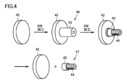
図4は、付加加工および除去加工に伴って変化するワークの形態を示す図である。図4を参照して、まず、母材42を準備する。母材42は、円盤形状を有する。次に、付加加工により、母材42の端面上に肉盛部43が形成された中間加工物46を得る。肉盛部43は、円柱形状を有する。次に、除去加工により、肉盛部43の外周面にネジ部44を形成する。最後に、母材42および肉盛部43の間を分離することにより、ネジ部44が形成された最終製品47を得る。
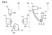
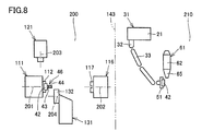
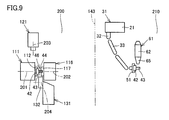
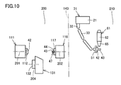
図5から図10は、この発明の実施の形態2におけるワークの加工方法の工程を模式的に表す図である。
図5を参照して、第2加工エリア210において、ワーク把持部51により母材42を把持する。ロボットアーム31を動作させることによって、把持したワーク41を付加加工用ヘッド61に接近させる。付加加工用ヘッド61から母材42に向けて材料粉末を吐出しつつ、レーザ光を照射することによって、母材42に肉盛部43を形成する(中間加工物46の製造)。
図6を参照して、次に、ロボットアーム31を第2加工エリア210から第1加工エリア200に移動させる。ロボットアーム31を動作させることによって、保持した中間加工物46を第2主軸台116に接近させる。肉盛部43が第2主軸117に対して所定位置に位置決めされたら、肉盛部43を第2主軸117によりチャッキングする。肉盛部43がチャッキングされたタイミングで、ワーク把持部51による母材42の把持を解除する。ロボットアーム31を第1加工エリア200から第2加工エリア210に退避させる。
図7を参照して、第1加工エリア200において、第1主軸台111および第2主軸台116を接近させる。母材42を第1主軸112によりチャッキングするとともに、第2主軸117による肉盛部43のチャッキングを解除することにより、中間加工物46を第2主軸台116から第1主軸台111に移し替える。一方、第2加工エリア210において、ワーク把持部51により新たな母材42を把持する。
図8を参照して、第1加工エリア200において、肉盛部43にネジ部44を形成するための除去加工を開始する。一方、第2加工エリア210において、母材42に肉盛部43を形成するための付加加工を開始する。
本実施の形態における加工機械100では、第1加工エリア200における除去加工と、第2加工エリア210における付加加工とを同時に進行させることが可能である。また、除去加工時、第1加工エリア200は、切削油の雰囲気下に置かれる。本実施の形態では、除去加工の間、付加加工用ヘッド61が第2加工エリア210にあるため、光学部品を備えた付加加工用ヘッド61が切削油に晒されることを防止できる。
図9を参照して、第1主軸112および第2主軸117の回転を同期させながら、第1主軸台111および第2主軸台116を接近させる。第2主軸117により、中間加工物46の肉盛部43の端部をチャッキングする。中間加工物46の両端が第1主軸台111および第2主軸台116により保持された状態で、母材42および肉盛部43の間を分離するための除去加工(突っ切り加工)を行なう。
図10を参照して、第1主軸台111に母材42が残り、第2主軸台116に最終製品47が残る。第1加工エリア200から、母材42および最終製品47を回収する。
このように構成された、この発明の実施の形態2における加工機械100および加工方法によれば、実施の形態1に記載の効果を同様に奏することができる。
(実施の形態3)
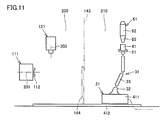
図11は、この発明の実施の形態3における加工機械を模式的に表す正面図である。本実施の形態における加工機械は、実施の形態1における加工機械100と比較して、基本的には同様の構造を有する。以下、重複する構造については、その説明を繰り返さない。
図11は、この発明の実施の形態3における加工機械を模式的に表す正面図である。本実施の形態における加工機械は、実施の形態1における加工機械100と比較して、基本的には同様の構造を有する。以下、重複する構造については、その説明を繰り返さない。
図11を参照して、本実施の形態における加工機械では、ロボットアーム31の移動機構部21が、台車部411およびレール412を有する。レール412は、第1加工エリア200および第2加工エリア210の間で直線状に延びている。レール412は、第1加工エリア200および第2加工エリア210の底部に設けられている。台車部411は、レール412上を走行可能に設けられている。
基部32は、移動機構部21(台車部411)から鉛直上方向に突出する形状を有する。基部32からアーム状に延出するアーム部33の構造は、実施の形態1における加工機械100と同様である。本実施の形態では、シャッタ144が、ロボットアーム31が移動する高さに合わせて、第1加工エリア200および第2加工エリア210の底部に近い位置に設けられている。
このように構成された、この発明の実施の形態3における加工機械によれば、実施の形態1に記載の効果を同様に奏することができる。
この発明に従った加工機械は、ワークの除去加工および付加加工が可能な加工機械である。加工機械は、第1加工エリアに設けられ、ワークを保持するワーク保持部と、第1加工エリアに設けられ、ワークの除去加工のための工具を保持する工具保持部と、第2加工エリアに設けられる付加加工用ヘッドと、ワークを保持し、第1加工エリアおよび第2加工エリアの間でワークを搬送するマニピュレータとを備える。付加加工用ヘッドは、ワークの付加加工時に、マニピュレータにより保持されたワークに対して材料を吐出する。
このように構成された加工機械によれば、ワークの付加加工時に、ワーク搬送用のマニピュレータにより保持されたワークに対して材料を吐出するため、第2加工エリアにワークを保持するための機構を別途設ける必要がない。このため、簡易な構成で、ワークの除去加工および付加加工が可能な加工機械を実現することができる。
また好ましくは、加工機械は、第2加工エリアに不活性ガスを供給する不活性ガス供給部と、第1加工エリアおよび第2加工エリアを隔てる隔壁部を有し、第2加工エリアを略密閉された空間に形成するカバー体とをさらに備える。
このように構成された加工機械によれば、第2加工エリアからの不活性ガスの漏洩を抑制することにより、ワークの付加加工時、第2加工エリアをより確実に不活性ガス雰囲気とすることができる。
また好ましくは、マニピュレータは、第1加工エリアおよび第2加工エリアの間で移動可能な移動機構部を有し、多軸制御可能なロボットアームである。
このように構成された加工機械によれば、ワークの付加加工時、ロボットアームにより保持されたワークと、付加加工用ヘッドとの相対的な位置関係を自在に変化させることができる。
今回開示された実施の形態はすべての点で例示であって制限的なものではないと考えられるべきである。本発明の範囲は上記した説明ではなくて請求の範囲によって示され、請求の範囲と均等の意味および範囲内でのすべての変更が含まれることが意図される。
この発明は、主に、ワークの除去加工および付加加工が可能なAM/SMハイブリッド加工機に適用される。
21 移動機構部、22 リニアガイド、23 ベース部材、25 ラックピニオン、31 ロボットアーム、32 基部、33 アーム部、33L 第1可動部、33M 第2可動部、33N 第3可動部、36 連結部、41 ワーク、42 母材、43 肉盛部、44 ネジ部、46 中間加工物、47 最終製品、51 ワーク把持部、61 付加加工用ヘッド、62 本体部、65 レーザ光出射部、66 開口部、68 光学部品、70 材料粉末供給装置、71 混合部、72 材料粉末タンク、73 管部材、76 レーザ発振装置、81 不活性ガスタンク、82 配管、86 酸素濃度検出センサ、100 加工機械、111 第1主軸台、112 第1主軸、116 第2主軸台、117 第2主軸、121 工具主軸、131 下刃物台、132 旋回部、141 ベッド、142 カバー体、143 隔壁部、144 シャッタ、200 第1加工エリア、201,202,203,204 中心軸、210 第2加工エリア、211,212,213 回動軸、214,215,216 回転軸、311 レーザ光、312 材料粉末、313 ガス、314 溶融点、315 肉盛素材、316 肉盛層、411 台車部、412 レール。
Claims (3)
- ワークの除去加工および付加加工が可能な加工機械であって、
第1加工エリアに設けられ、ワークを保持するワーク保持部と、
前記第1加工エリアに設けられ、ワークの除去加工のための工具を保持する工具保持部と、
第2加工エリアに設けられる付加加工用ヘッドと、
ワークを保持し、前記第1加工エリアおよび前記第2加工エリアの間でワークを搬送するマニピュレータとを備え、
前記付加加工用ヘッドは、ワークの付加加工時に、前記マニピュレータにより保持されたワークに対して材料を吐出する、加工機械。 - 前記第2加工エリアに不活性ガスを供給する不活性ガス供給部と、
前記第1加工エリアおよび前記第2加工エリアを隔てる隔壁部を有し、前記第2加工エリアを略密閉された空間に形成するカバー体とをさらに備える、請求項1に記載の加工機械。 - 前記マニピュレータは、前記第1加工エリアおよび前記第2加工エリアの間で移動可能な移動機構部を有し、多軸制御可能なロボットアームである、請求項1または2に記載の加工機械。
Priority Applications (3)
| Application Number | Priority Date | Filing Date | Title |
|---|---|---|---|
| US15/576,300 US10377002B2 (en) | 2015-05-25 | 2016-04-07 | Manufacturing machine |
| CN201680030145.3A CN107735215B (zh) | 2015-05-25 | 2016-04-07 | 加工机械 |
| DE112016002368.5T DE112016002368T5 (de) | 2015-05-25 | 2016-04-07 | Fertigungsmaschine |
Applications Claiming Priority (2)
| Application Number | Priority Date | Filing Date | Title |
|---|---|---|---|
| JP2015-105249 | 2015-05-25 | ||
| JP2015105249A JP5940712B1 (ja) | 2015-05-25 | 2015-05-25 | 加工機械 |
Publications (1)
| Publication Number | Publication Date |
|---|---|
| WO2016189981A1 true WO2016189981A1 (ja) | 2016-12-01 |
Family
ID=56244663
Family Applications (1)
| Application Number | Title | Priority Date | Filing Date |
|---|---|---|---|
| PCT/JP2016/061390 Ceased WO2016189981A1 (ja) | 2015-05-25 | 2016-04-07 | 加工機械 |
Country Status (5)
| Country | Link |
|---|---|
| US (1) | US10377002B2 (ja) |
| JP (1) | JP5940712B1 (ja) |
| CN (1) | CN107735215B (ja) |
| DE (1) | DE112016002368T5 (ja) |
| WO (1) | WO2016189981A1 (ja) |
Cited By (1)
| Publication number | Priority date | Publication date | Assignee | Title |
|---|---|---|---|---|
| DE102017009398B4 (de) | 2016-10-11 | 2022-05-12 | Fanuc Corporation | Werkzeugmaschine |
Families Citing this family (37)
| Publication number | Priority date | Publication date | Assignee | Title |
|---|---|---|---|---|
| US20170129180A1 (en) | 2014-06-09 | 2017-05-11 | Hybrid Manufacturing Technologies Limited | Material processing methods and related apparatus |
| JP6033368B1 (ja) * | 2015-06-15 | 2016-11-30 | Dmg森精機株式会社 | 加工機械 |
| JP6735148B2 (ja) * | 2016-05-11 | 2020-08-05 | オークマ株式会社 | 工作機械 |
| JP6487373B2 (ja) | 2016-05-25 | 2019-03-20 | ファナック株式会社 | ワーク固定装置 |
| WO2018033973A1 (ja) * | 2016-08-17 | 2018-02-22 | ヤマザキマザック株式会社 | 複合加工装置及び複合加工方法 |
| JP6525933B2 (ja) | 2016-10-11 | 2019-06-05 | ファナック株式会社 | 工作機械 |
| CN106312574B (zh) * | 2016-10-31 | 2018-11-02 | 华中科技大学 | 一种大幅面零部件的增减材复合制造设备 |
| JP6731329B2 (ja) * | 2016-11-10 | 2020-07-29 | Dmg森精機株式会社 | 三次元形状物製造装置 |
| JP2018161724A (ja) | 2017-03-27 | 2018-10-18 | ファナック株式会社 | 工作機械システムおよびクランプ方法 |
| EP3626369B1 (en) | 2017-05-16 | 2023-04-19 | Toshiba Kikai Kabushiki Kaisha | Additive manufacturing device |
| DE102017121526A1 (de) * | 2017-09-15 | 2019-03-21 | Rollomatic S.A. | Vorrichtung zur Ausrichtung und Positionierung eines Werkstücks relativ zu einem Laserstrahl einer Laserbearbeitungsmaschine |
| WO2019112192A1 (ko) * | 2017-12-04 | 2019-06-13 | 주식회사 진영코퍼레이션 | 공작물 자동 공급 장치 |
| US11097484B1 (en) * | 2018-02-13 | 2021-08-24 | Made In Space, Inc. | System and method for hybrid additive and subtractive manufacturing with part movement |
| JP6994411B2 (ja) * | 2018-02-28 | 2022-01-14 | オークマ株式会社 | 工作機械システム |
| DE102018204143B4 (de) * | 2018-03-19 | 2025-03-27 | Ford Global Technologies, Llc | Additives Fertigungsverfahren |
| US11426818B2 (en) | 2018-08-10 | 2022-08-30 | The Research Foundation for the State University | Additive manufacturing processes and additively manufactured products |
| US10780498B2 (en) * | 2018-08-22 | 2020-09-22 | General Electric Company | Porous tools and methods of making the same |
| DE102018122499A1 (de) * | 2018-09-14 | 2020-03-19 | HELLA GmbH & Co. KGaA | Einrichtung mit einem ersten und einem zweiten Roboter und Verfahren zu deren Betrieb |
| FR3087703B1 (fr) * | 2018-10-25 | 2020-12-04 | Poietis | Systeme de bio-impression robotise |
| TWI689368B (zh) * | 2018-12-03 | 2020-04-01 | 財團法人金屬工業研究發展中心 | 複合式雷射加工裝置 |
| CN109604598A (zh) * | 2019-01-09 | 2019-04-12 | 深圳光韵达光电科技股份有限公司 | 一种增减材复合加工设备 |
| JP7213744B2 (ja) * | 2019-04-23 | 2023-01-27 | オークマ株式会社 | 3次元形状加工方法 |
| JP6745945B1 (ja) * | 2019-05-15 | 2020-08-26 | Dmg森精機株式会社 | 加工機械 |
| JP2020196020A (ja) * | 2019-05-31 | 2020-12-10 | 株式会社ジェイテクト | 金属付加製造装置 |
| DE102019213381A1 (de) * | 2019-09-04 | 2021-03-04 | Guangdong Yizumi Precision Machinery Co., Ltd. | Extruder einer Werkzeugmaschine zur additiven Fertigung |
| DE102019213384A1 (de) * | 2019-09-04 | 2021-03-04 | Guangdong Yizumi Precision Machinery Co., Ltd. | Werkzeugmaschine zur additiven Fertigung mit einem Extruder |
| DE102019215814B4 (de) | 2019-10-15 | 2023-12-07 | Guangdong Yizumi Precision Machinery Co., Ltd. | Vorrichtung und Verfahren zur additiven Fertigung von Bauteilen |
| IT201900023982A1 (it) * | 2019-12-13 | 2021-06-13 | Cms Spa | Centro di lavoro a controllo numerico |
| JP7364478B2 (ja) * | 2020-01-23 | 2023-10-18 | オークマ株式会社 | 工作機械 |
| DE102020002815B3 (de) | 2020-05-12 | 2021-07-15 | Günther Zimmer | Bearbeitungsroboter zur spanenden Bearbeitung |
| CN117440874A (zh) * | 2021-06-04 | 2024-01-23 | Dmg森精機株式会社 | 作业机械 |
| BG67645B1 (bg) | 2021-06-28 | 2024-08-15 | Технически Университет - София | Производствена система за хибридна обработка чрез стружкоотнемане и електродъгово добавяне на материал |
| US20260054335A1 (en) * | 2021-09-06 | 2026-02-26 | Jtekt Corporation | Composite grinding machine |
| CN113909695A (zh) * | 2021-10-01 | 2022-01-11 | 江苏烁石焊接科技有限公司 | 一种大型复杂构件的智能协同增减材复合成型装备 |
| CN114274116B (zh) * | 2021-12-17 | 2023-09-05 | 武汉数字化设计与制造创新中心有限公司 | 一种水轮机移动式机器人增减材混合制造装置 |
| DE102022200690A1 (de) | 2022-01-21 | 2023-06-07 | Zf Friedrichshafen Ag | Verfahren zur automatisierten Herstellung eines Bauteils in einer Produktionszelle und Produktionszelle |
| JP7678920B1 (ja) | 2024-10-04 | 2025-05-16 | ヤマザキマザック株式会社 | 工作機械、および、ワーク加工方法 |
Citations (3)
| Publication number | Priority date | Publication date | Assignee | Title |
|---|---|---|---|---|
| WO1997024217A1 (fr) * | 1995-12-31 | 1997-07-10 | Shinko Sellbic Co., Ltd. | Procede de moulage sans moule, equipement approprie |
| JP2007146216A (ja) * | 2005-11-25 | 2007-06-14 | Matsushita Electric Works Ltd | 三次元形状造形物製造装置 |
| US20130015596A1 (en) * | 2011-06-23 | 2013-01-17 | Irobot Corporation | Robotic fabricator |
Family Cites Families (14)
| Publication number | Priority date | Publication date | Assignee | Title |
|---|---|---|---|---|
| US6314686B1 (en) * | 1999-12-16 | 2001-11-13 | Genesis Systems Group, Ltd. | Light seal for use with robotic equipment |
| US6621091B2 (en) * | 2000-03-03 | 2003-09-16 | Motoman, Inc. | Workpiece enclosure and processing system |
| US6649868B2 (en) * | 2000-03-03 | 2003-11-18 | Motoman, Inc. | Workpiece enclosure system and robotic laser processing system including pass through partitions |
| US20040096586A1 (en) * | 2002-11-15 | 2004-05-20 | Schulberg Michelle T. | System for deposition of mesoporous materials |
| JP2004314168A (ja) | 2003-04-18 | 2004-11-11 | Katsushige Yamada | ポンプ機器類のレーザ肉盛装置及び肉盛方法 |
| JP2011241450A (ja) * | 2010-05-19 | 2011-12-01 | Keijiro Yamamoto | 積層造形方法及び積層造形装置 |
| JP5622636B2 (ja) | 2011-03-29 | 2014-11-12 | 株式会社東芝 | 補修装置および補修方法 |
| US8867101B2 (en) * | 2011-10-18 | 2014-10-21 | Think Laboratory Co., Ltd. | Photoengraving consumable material remote administration method |
| KR20160004304A (ko) * | 2013-04-29 | 2016-01-12 | 레클루즈 모터 스포츠, 아이엔씨. | 로봇 텐딩을 사용한 다양한 부품 형상 저장과 처리를 위한 시스템 및 방법 |
| US10213876B2 (en) * | 2013-11-12 | 2019-02-26 | Magna International Inc. | System and method for high output laser trimming |
| CN203599850U (zh) | 2013-12-02 | 2014-05-21 | 嵇纪新 | 自动化组合机床 |
| JP6320123B2 (ja) * | 2014-03-31 | 2018-05-09 | 三菱重工業株式会社 | 三次元積層装置及び三次元積層方法 |
| CN203843168U (zh) | 2014-05-22 | 2014-09-24 | 华中科技大学 | 一种高能束增材制造大尺寸金属零部件的设备 |
| CN104384936B (zh) * | 2014-09-18 | 2017-04-12 | 大连理工大学 | 一种增减材复合制造机床 |
-
2015
- 2015-05-25 JP JP2015105249A patent/JP5940712B1/ja active Active
-
2016
- 2016-04-07 DE DE112016002368.5T patent/DE112016002368T5/de active Pending
- 2016-04-07 US US15/576,300 patent/US10377002B2/en active Active
- 2016-04-07 CN CN201680030145.3A patent/CN107735215B/zh active Active
- 2016-04-07 WO PCT/JP2016/061390 patent/WO2016189981A1/ja not_active Ceased
Patent Citations (3)
| Publication number | Priority date | Publication date | Assignee | Title |
|---|---|---|---|---|
| WO1997024217A1 (fr) * | 1995-12-31 | 1997-07-10 | Shinko Sellbic Co., Ltd. | Procede de moulage sans moule, equipement approprie |
| JP2007146216A (ja) * | 2005-11-25 | 2007-06-14 | Matsushita Electric Works Ltd | 三次元形状造形物製造装置 |
| US20130015596A1 (en) * | 2011-06-23 | 2013-01-17 | Irobot Corporation | Robotic fabricator |
Cited By (1)
| Publication number | Priority date | Publication date | Assignee | Title |
|---|---|---|---|---|
| DE102017009398B4 (de) | 2016-10-11 | 2022-05-12 | Fanuc Corporation | Werkzeugmaschine |
Also Published As
| Publication number | Publication date |
|---|---|
| US20180141174A1 (en) | 2018-05-24 |
| JP2016215346A (ja) | 2016-12-22 |
| CN107735215A (zh) | 2018-02-23 |
| CN107735215B (zh) | 2020-10-16 |
| US10377002B2 (en) | 2019-08-13 |
| JP5940712B1 (ja) | 2016-06-29 |
| DE112016002368T5 (de) | 2018-02-15 |
Similar Documents
| Publication | Publication Date | Title |
|---|---|---|
| JP5940712B1 (ja) | 加工機械 | |
| JP5937249B1 (ja) | 加工機械 | |
| JP5937248B1 (ja) | ワークの加工方法 | |
| CN107735209B (zh) | 加工机械 | |
| JP5937713B1 (ja) | 加工機械 | |
| JP6660681B2 (ja) | 加工機械 | |
| JP6785055B2 (ja) | 加工機械 | |
| JP6810823B1 (ja) | ワークの付加加工方法および加工機械 | |
| JPWO2017115406A1 (ja) | 付加加工用ヘッド、加工機械および加工方法 | |
| JPWO2018033973A1 (ja) | 複合加工装置及び複合加工方法 | |
| JP2018075778A (ja) | 三次元形状物製造装置 | |
| CN117440874A (zh) | 作业机械 | |
| WO2022091266A1 (ja) | 複合加工機 | |
| CN115768592A (zh) | 金属制品的再加工方法 |
Legal Events
| Date | Code | Title | Description |
|---|---|---|---|
| 121 | Ep: the epo has been informed by wipo that ep was designated in this application |
Ref document number: 16799689 Country of ref document: EP Kind code of ref document: A1 |
|
| WWE | Wipo information: entry into national phase |
Ref document number: 15576300 Country of ref document: US |
|
| WWE | Wipo information: entry into national phase |
Ref document number: 112016002368 Country of ref document: DE |
|
| 122 | Ep: pct application non-entry in european phase |
Ref document number: 16799689 Country of ref document: EP Kind code of ref document: A1 |