WO2016189854A1 - 軌条車両用台車及びそれを備えた軌条車両 - Google Patents
軌条車両用台車及びそれを備えた軌条車両 Download PDFInfo
- Publication number
- WO2016189854A1 WO2016189854A1 PCT/JP2016/002500 JP2016002500W WO2016189854A1 WO 2016189854 A1 WO2016189854 A1 WO 2016189854A1 JP 2016002500 W JP2016002500 W JP 2016002500W WO 2016189854 A1 WO2016189854 A1 WO 2016189854A1
- Authority
- WO
- WIPO (PCT)
- Prior art keywords
- nut
- spacer
- receiving seat
- bolt
- vehicle
- Prior art date
- Legal status (The legal status is an assumption and is not a legal conclusion. Google has not performed a legal analysis and makes no representation as to the accuracy of the status listed.)
- Ceased
Links
Images










Classifications
-
- B—PERFORMING OPERATIONS; TRANSPORTING
- B61—RAILWAYS
- B61F—RAIL VEHICLE SUSPENSIONS, e.g. UNDERFRAMES, BOGIES OR ARRANGEMENTS OF WHEEL AXLES; RAIL VEHICLES FOR USE ON TRACKS OF DIFFERENT WIDTH; PREVENTING DERAILING OF RAIL VEHICLES; WHEEL GUARDS, OBSTRUCTION REMOVERS OR THE LIKE FOR RAIL VEHICLES
- B61F5/00—Constructional details of bogies; Connections between bogies and vehicle underframes; Arrangements or devices for adjusting or allowing self-adjustment of wheel axles or bogies when rounding curves
- B61F5/02—Arrangements permitting limited transverse relative movements between vehicle underframe or bolster and bogie; Connections between underframes and bogies
- B61F5/16—Centre bearings or other swivel connections between underframes and bolsters or bogies
Definitions
- the present invention relates to a rail vehicle carriage and a rail vehicle including the same.
- the driving force of the bogie or the braking force of the brake is transmitted from the bogie to the vehicle body by connecting the central pin of the vehicle body and the bogie frame by one traction link extending in the longitudinal direction of the vehicle.
- This link type traction device may be provided (for example, refer to patent documents 1).
- a receiving seat for fixing to the vehicle longitudinal direction end portion of the traction link is integrally provided on the center pin and the carriage frame, respectively.
- the traction link and the receiving seat are fixed with bolts, and the receiving seat is formed with a screw hole having an inner peripheral surface with a female screw to be screwed with a male screw of the bolt.
- an object of the present invention is to provide a rail vehicle carriage provided with a suitable one-link traction device capable of improving workability and maintainability.
- a rail vehicle bogie includes a bogie frame, and a one-link traction device that couples the bogie frame and the vehicle body and transmits a force acting on the bogie frame to the vehicle body.
- the one-link traction device is provided on a fixed object that connects a central pin of the vehicle body and the bogie frame and extends in the vehicle longitudinal direction and the central pin or the bogie frame.
- the receiving seat is formed with an insertion hole through which the bolt is inserted, and the end of the link member and the receiving seat are fixed by screwing the nut into the bolt. Therefore, it is not necessary to form a screw hole to be screwed to the bolt, and workability can be improved. And even if the torque management at the time of fastening between the bolt and the nut is wrong and the screw hole is damaged, the nut in which the screw hole is formed can be replaced. Therefore, maintenance and the like can be improved.
- FIG. 2 is a view around a receiving seat provided in the bogie frame of FIG. 1. It is the figure which extracted only the receiving seat from FIG.
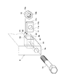
- FIG. 3 is a perspective view of a state where a fastening member and a spacer are removed from the receiving seat of FIG. 2. It is a figure which shows the state in which the nut of FIG. 2 was accommodated in the nut accommodation space of a receiving seat. It is a figure equivalent to FIG. 2 of the 1 link type traction apparatus of the rail vehicle trolley
- FIG. 10 is a view corresponding to FIG. 9 of a one-link traction device for a rail vehicle dolly according to a seventh embodiment.
- FIG. 1 is a side view of the periphery of a single link traction device 1 in a rail vehicle 10 provided with a rail vehicle carriage 5 according to the present embodiment.
- the rail vehicle 10 includes a vehicle body 3 and a rail vehicle cart 5 (hereinafter referred to as a cart 5) that supports the vehicle body 3.
- a center pin 4 is fixed to the lower surface of the pillow beam 3 a of the vehicle body 3 by a bolt 15.
- the cart 5 is a so-called bolsterless cart that does not have a pillow beam.
- the vehicle body 3 is coupled to a bogie frame 6 via a single-link traction device 1 of the bogie 5.
- the single link type traction device 1 has a single link member 2 extending in the longitudinal direction of the vehicle.
- the link member 2 connects the center pin 4 and the bogie frame 6.
- the carriage frame 6 includes a horizontal beam 6a extending in the vehicle width direction.
- a motor (not shown) is fixed to the side beam 6a, and the driving force of the motor is transmitted to the wheels of the carriage 5 through a speed reducer or the like to drive the carriage 5.
- a brake device (not shown) is fixed to the carriage 5 via a mounting seat. The force acting on the carriage frame 6 such as the driving force of the carriage 5 or the braking force of the brake is transmitted from the lateral beam 6 a of the carriage frame 6 to the center pin 4 through the link member 2.
- the link member 2 has pivot portions 21 that are fixed to the center pin 4 or the carriage frame 6 at both ends in the longitudinal direction of the vehicle.
- the pivot portion 21 faces the lateral beam 6a in the vertical direction.
- the pivot portion 21 includes a cylindrical portion 21a, a mandrel 21b, and a rubber bush 21c.
- the cylindrical portion 21a is open on both sides in the vehicle width direction, and a mandrel 21b is inserted through the cylindrical portion 21a via a rubber bush 21c.
- the mandrel 21b protrudes from the openings on both sides in the vehicle width direction of the cylindrical portion 21a.
- the both ends of the mandrel 21b in the vehicle width direction are fixed to the center pin 4 and the carriage frame 6, respectively. That is, in the present embodiment, the center pin 4 and the carriage frame 6 are objects to be fixed to the link member 2. Then, the mandrel 21b of the pivot portion 21 corresponding to the vehicle longitudinal direction end portion of the link member 2 is fixed to the fixed object.
- the center pin 4 and the carriage frame 6 that are fixed objects are provided with receiving seats 8 and 9 that are fixed to the mandrel 21b of the link member 2, respectively.
- the receiving seats 8 and 9 are metal members.
- the receiving seat 8 is joined to the lower surface of the center pin 4 by welding and is provided integrally with the center pin 4.
- the receiving seat 9 is joined to the lower surface of the horizontal beam 6 a of the carriage frame 6 by welding and is provided integrally with the carriage frame 6.
- the receiving seat 9 is formed integrally with a motor case (not shown) that accommodates the motor of the carriage 5.
- the receiving seats 8 and 9 are fixed by the mandrel 21b of the link member 2 and the first fastening member 7, respectively.
- FIG. 2 is a view around the receiving seat 9 provided in the bogie frame 6 of FIG.
- the first fastening member 7 includes a bolt 71 inserted into the mandrel 21 b and the receiving seat 9 from one side in the vehicle longitudinal direction, and a nut 72 screwed into the bolt 71 from the other side in the vehicle longitudinal direction.
- the mandrel 21b and the receiving seat 9 are respectively formed with insertion holes 21d and 9a through which the bolts 71 are inserted.
- the nut 72 is formed with a screw hole 72a having a female screw threadedly engaged with the male screw of the bolt 71 on the inner peripheral surface.
- the bolt 71 is a hexagonal bolt whose head has a hexagonal outer shape
- the nut 72 is a hexagonal nut whose outer shape is a hexagonal (see FIG. 4).
- FIG. 3 is a diagram in which only the receiving seat 9 is extracted from FIG.
- FIG. 4 is a perspective view of a state in which the first fastening member 7 and the spacer 11 are removed from the receiving seat 9 shown in FIG.
- FIG. 5 is a front view showing a state in which the nut 72 of FIG. 2 is housed in the nut housing space V ⁇ b> 1 of the receiving seat 9.
- illustration of the link member 2 is abbreviate
- the receiving seat 9 is formed with a nut housing space V1 for housing the nut 72.
- the nut housing space V1 is an internal space of the square hole 9b that penetrates the receiving seat 9 in the vehicle width direction.
- the square hole 9b is a substantially quadrangular square hole in a side view.
- the nut housing space V1 communicates with the internal space of the insertion hole 9a through which the bolt 71 is inserted. Further, the nut housing space V1 is orthogonal to the first surface S1 and the second surface S2 facing the nut 72 in the longitudinal direction of the vehicle (the axial direction of the bolt 71), and to the axis J1 of the bolt 71 with respect to the nut 72. It is formed by the third surface S3 facing in the direction. In the present embodiment, the third surface S ⁇ b> 3 has surfaces that are located with gaps on both sides of the nut 72 in the vertical direction.
- the shortest distance L between the third surface S3 and the axis J1 of the bolt 71 is smaller than the maximum radius R of the nut 72 when viewed from the direction of the axis J1 (see FIG. 5).
- the square hole 9b is formed by cutting using an end mill as a tool.
- the end mill has a substantially cylindrical shape, and a plurality of blades are provided in the circumferential direction at the tip portion. For example, an angle penetrating in the vehicle width direction by moving the end mill by a predetermined distance in the vehicle width direction and the vehicle longitudinal direction while rotating the end mill about the axis extending in the vehicle width direction with respect to the seat 9.
- a hole 9b is formed.
- the locus drawn by the outer diameter of the end mill is an arc, so that each of the four corners of the square hole 9b is an arc surface.
- the corners of the square holes 9b are formed by the first surface S1, the third surface S3, the second surface S2, and the third surface S3, and the nut of the first surface S1 in the nut housing space V1.
- the opposing region A facing the fastening surface 72b of 72 is not seen in the plane part parallel to the fastening surface 72b of the nut 72 and the fastening surface 72b of the nut 72 located on both upper and lower sides of the plane part when viewed from the vehicle width direction.
- a spacer 11 which is a metal member is accommodated in the nut accommodating space V1.
- the spacer 11 is sandwiched between the first surface S ⁇ b> 1 and the fastening surface 72 b of the nut 72.
- the spacer 11 is formed with a first insertion hole 11a through which the bolt 71 is inserted.
- the surface 11b on the first surface S1 side of the spacer 11 has the same shape as the facing region A of the first surface S1, and has a shape having arcuate surface portions on both upper and lower sides of the flat surface portion.
- the surface 11c on the fastening surface 72b side of the spacer 11 has the same shape as the fastening surface 72b and a planar shape.
- the bolt 71 is fixed to the mandrel 21b, the receiving seat 9 and the spacer 11 in the vehicle longitudinal direction with the spacer 11 and the nut 72 accommodated in the nut accommodating space V1. Insert from one side. Then, by rotating the bolt 71 around the axis J1 and fastening the female screw of the screw hole 72a formed in the nut 72 to the male screw of the bolt 71, the mandrel 21b of the link member 2 and the receiving seat 9 are fixed. .
- the surface 11b on the first surface S1 side of the spacer 11 is in surface contact with the facing region A of the first surface S1, and on the other hand, the fastening surface 72b of the spacer 11
- the side surface 11 c is in surface contact with the fastening surface 72 b of the nut 72.
- the receiving seat 9 has a base 90, a first projecting portion 91, a second projecting portion 92, and a connecting portion 93.
- the base 90 is a portion of the receiving seat 9 that is positioned above the nut housing space V1 and is joined to the carriage frame 6 that is a fixed object by welding.
- the base part 90 contains 3rd surface S3 located above the nut 72 among the surfaces which form nut accommodation space V1. From the vehicle longitudinal direction one side of the base 90, the 1st protrusion part 91 protrudes below.
- the 1st protrusion part 91 contains 1st surface S1 located in the vehicle longitudinal direction one side of the nut 72 among the surfaces which form the nut accommodation space V1, and the protrusion end is below from the nut accommodation space V1. It extends. Further, the above-described insertion hole 9 a through which the bolt 71 is inserted is formed in the first projecting portion 91.
- a second projecting portion 92 projects downward from the other side of the base portion 90 in the longitudinal direction of the vehicle.
- the second projecting portion 92 projects so as to overlap the first projecting portion 91 when viewed from one side in the vehicle longitudinal direction.
- the 2nd protrusion part 92 contains 2nd surface S2 located in the vehicle longitudinal direction other side of the nut 72 among the surfaces which form nut accommodation space V1.
- the first projecting portion 91 and the second projecting portion 92 are connected on the projecting end side of the first projecting portion 91 from the axis J1 of the bolt 71 by a connecting portion 93 extending in the vehicle longitudinal direction.
- the connecting portion 93 includes a third surface S3 located below the nut 72 among the surfaces forming the nut housing space V1.
- the one-link traction device 1 of the rail vehicle 10 configured as described above has the following effects.
- an insertion hole 9 a for inserting the bolt 71 is formed, and a nut 72 is screwed into the bolt 71 to fix the mandrel 21 b of the link member 2 and the receiving seat 9.
- the driving force or the braking force of the carriage 5 is transmitted from the carriage 5 to the vehicle body 3 by one link member 2, thereby acting on the receiving seats 8 and 9 fixed to the link member 2. Since the load increases, it is necessary to secure the strength of the receiving seats 8 and 9.
- the link member 2 is fixed to the receiving seat 9 with bolts 71 and nuts 72, the first projecting portion is simply removed from the base portion joined to the carriage frame 6 that is a fixing object. If it is only projected, the first projecting portion is supported in a cantilever state, and when a driving force or a braking force of a brake is transmitted from the carriage to the vehicle body, the load in the longitudinal direction of the vehicle is reduced.
- the first projecting portion 91 is connected to the first projecting portion 91 by the connecting portion 93 on the projecting end side of the first projecting portion 91 with respect to the axis J1 of the bolt 71.
- the nut 72 is accommodated in the nut accommodating space V ⁇ b> 1 so that the shortest distance L between the third surface S ⁇ b> 3 of the receiving seat 9 and the axis J ⁇ b> 1 of the bolt 71 is smaller than the maximum radius R of the nut 72. .
- the third surface S3 of the receiving seat 9 is positioned as an obstacle wall on the rotation locus of the nut 72 having the maximum radius R as the rotation radius. It is possible to prevent the nut 72 from coming into contact with the third surface S3 of the receiving seat 9 at the time of fastening with the bolt 71 and the nut 72 to rotate together.
- the nut housing space V1 is configured by the internal space of the square hole 9b. Since the corner of the square hole 9b becomes an arc surface by cutting, the first surface S1 constituting the nut housing space V1 also has a shape having an arc surface. In the first surface S1, the fastening surface 72b of the nut 72 and The opposing area A which opposes becomes a shape different from the fastening surface 72b which is planar shape. In such a configuration, when the bolt 71 and the nut 72 are fastened, the nut 72 is in point contact with the first surface S1, and a gap is generated between the fastening surface 72b and the first surface S1, and the fastening force is increased. However, it is not sufficiently transmitted to the fixing portion between the mandrel 21b of the link member 2 and the seat 9 and cannot be firmly fixed.
- the spacer 11 is sandwiched between the first surface S1 and the fastening surface 72b of the nut 72, and the spacer 11 is opposed to the fastening region 72b of the first surface S1.
- Each of the surfaces 11b and 11c has the same shape as 72b. Accordingly, when the bolt 71 and the nut 72 are fastened, the surface 11b on the first surface S1 side of the spacer 11 and the first surface S1 are in surface contact with each other, and the surface 11c on the fastening surface 72b side of the spacer 11 and the fastening surface 72b are both. Because of the surface contact, the mandrel 21b of the link member 2 and the receiving seat 9 can be firmly fixed.
- a one-link traction device 200 for a rail vehicle trolley according to the second embodiment is obtained by partially modifying the receiving seat 9 according to the first embodiment.
- the receiving seat 209 which concerns on 2nd Embodiment is demonstrated centering on a different point from 1st Embodiment.
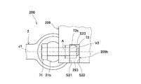
- FIG. 6 is a view corresponding to FIG. 2 of the one-link traction device 200 of the rail vehicle bogie according to the present embodiment.
- FIG. 7 is a view corresponding to FIG. 4 of the single-link traction device 200 of the rail vehicle bogie according to the second embodiment.
- FIG. 8 is a view as seen from the VIII direction shown in FIG.
- the receiving seat 209 is formed with a notch 209b in which a side surface and a lower surface on one side in the vehicle width direction are partially opened.
- the nut housing space V2 is a space that is surrounded by a surface constituting the notch 209b.
- the third surface S23 forming the nut housing space V2 has a surface S231 located above the nut 72 and a surface S232 located on the other side of the nut 72 in the vehicle width direction.
- the notch 209b is formed by cutting using an end mill, for example.
- the surface that forms the notch 209b by moving the end mill by a predetermined distance in the vehicle width direction and the vehicle longitudinal direction while rotating the end mill about the axis extending in the vertical direction with respect to the lower surface of the receiving seat 209. Is formed.
- the portions where the first surface S21, the third surface S232, the second surface S22, and the third surface S232 intersect each other form an arc surface due to the locus drawn by the outer diameter of the end mill during cutting. Yes.
- the nut 72 is accommodated in a position away from the corner to one side in the vehicle width direction so as not to contact the corner of the notch 209b when the nut 72 is fastened with the bolt 71 in the nut accommodating space V2.
- region A which opposes the fastening surface 72b of the nut 72 of 1st surface S1 becomes the same planar shape as the fastening surface 72b of the nut 72.
- the nut 72 is placed in the nut housing space V2 so that the shortest distance between the third surface S231 of the receiving seat 209 and the axis J1 of the bolt 71 is smaller than the maximum radius R of the nut 72 when viewed from the direction of the axis J1. Is housed in.
- the first protrusion 291 and the second protrusion 292 protrude downward from the base 90. Both projecting ends of the first projecting portion 291 and the second projecting portion 292 extend to the lower surface of the receiving seat 209. Further, since the notch 209b is not cut so as to penetrate the receiving seat 209 in the vehicle width direction, the third surface S3 forming the nut housing space V2 and the side surface of the receiving seat 209 on the other side in the vehicle width direction There is a side wall between them.
- a portion of the side wall that connects the first protruding portion 291 and the second protruding portion 292 on the protruding end side of the first protruding portion 291 from the axis J1 of the bolt 71 corresponds to the connecting portion 293.
- the configuration is the same as that of the first embodiment.
- region A with the fastening surface 72b of the nut 72 of 1st surface S1 is the same shape as the fastening surface 72b of the nut 72, and the spacer 11 is used when the bolt 71 and the nut 72 are fastened.
- the fastening surface 72b can be brought into surface contact with the first surface S21, the number of components can be reduced.
- the shortest distance between the third surface S231 of the receiving seat 209 and the axis J1 of the bolt 71 is smaller than the maximum radius R of the nut 72, even if the nut 72 rotates around the axis J1, the maximum radius R
- the third surface S231 of the receiving seat 209 is positioned as an obstacle wall on the rotation locus of the nut 72 having a rotation radius of. Therefore, it is possible to prevent the nut 72 from coming into contact with the third surface S231 of the receiving seat 209 when the bolt 71 is fastened, and the nut 72 rotating together.
- the nut 72 may be housed in the nut housing space V2 such that the shortest distance between the third surface S232 of the receiving seat 209 and the axis J1 of the bolt 71 is smaller than the maximum radius R of the nut 72.
- the facing area A of the first surface S21 facing the fastening surface 72b of the nut 72 has a shape different from that of the fastening surface 72b. Therefore, the facing area A of the first surface S21 has the same shape as the fastening surface 72b. It is preferable to sandwich a spacer having a gap between the first surface S21 and the fastening surface 72b.
- a one-link traction device 300 for a rail vehicle bogie according to the third embodiment is a partial modification of the receiving seat 9 according to the first embodiment.
- the receiving seat 309 which concerns on 3rd Embodiment is demonstrated centering on a different point from 1st Embodiment.
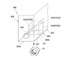
- FIG. 9 is a view corresponding to FIG. 4 of the single-link traction device 300 of the rail vehicle bogie according to the present embodiment.
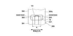
- FIG. 10 is a view corresponding to FIG. 8 of the one-link traction device 300 of the rail vehicle bogie according to the present embodiment.
- the receiving seat 309 is formed with a square hole 309b that partially opens the lower surface.
- the square hole 309b has a quadrangular shape when viewed in the vertical direction.
- the nut housing space V3 is an internal space of the square hole 309b and is recessed in the lower surface 309c of the receiving seat 309.
- the third surface S33 forming the nut housing space V3 has a surface S331 located above the nut 72 and surfaces S332 and S333 located on both sides of the nut 72 in the vehicle width direction. . Further, when the square hole 309b is formed by cutting, the corner portion of the square hole 309b becomes an arc surface by a locus drawn by the outer diameter of the end mill at the time of cutting.
- the nut 72 is accommodated in the nut accommodating space V3 so as not to contact the corner of the square hole 309b when fastened to the bolt 71.
- region A which opposes the fastening surface 72b of the nut 72 of 1st surface S31 becomes the same planar shape as the fastening surface 72b of the nut 72.
- the nut 72 is placed in the nut housing space V3 so that the shortest distance between the third surface S331 of the receiving seat 309 and the axis J1 of the bolt 71 is smaller than the maximum radius R of the nut 72 when viewed from the direction of the axis J1. Is housed in.
- the first projecting portion 391 and the second projecting portion 392 project downward from the base 90. Both protruding ends of the first protruding portion 391 and the second protruding portion 392 extend to the lower surface of the receiving seat 309. Further, in the receiving seat 309, there are side walls between the third surface S332 and the side surface on one side in the vehicle width direction of the receiving seat 309, and between the third surface S333 and the side surface on the other side in the vehicle width direction of the receiving seat 309, respectively. Exists.
- a portion connecting the first protruding portion 391 and the second protruding portion 392 on the protruding end side of the first protruding portion 391 from the axis J1 of the bolt 71 corresponds to the connecting portion 393.
- the connecting portion 393 is a wall portion that is located on both sides of the nut 72 in the vehicle width direction and forms the nut accommodating space V3. Other than this, the configuration is the same as that of the first embodiment.
- the same effect as that of the first embodiment can be obtained by the third embodiment. Furthermore, in 3rd Embodiment, compared with the structure which has the connection part only in the vehicle width direction one side of a nut by the receiving seat 309 having the connection part 393 on the vehicle width direction both sides of the nut 72, Since the load acting on the first projecting portion 391 of the receiving seat 309 is distributed to the plurality of connecting portions 393 and transmitted to the second projecting portion 392, the load is prevented from concentrating on one connecting portion, and received. It becomes easier to ensure the strength of the entire seat 309.
- the nut housing space V3 is a wall portion that is recessed in the lower surface 309c of the receiving seat 309, and the connecting portions 393 are positioned on both sides of the nut 72 in the vehicle width direction to form the nut housing space V3.
- the shortest distance between the third surface S331 of the receiving seat 309 and the axis J1 of the bolt 71 is smaller than the maximum radius R of the nut 72, even if the nut 72 rotates around the axis J1, the maximum radius R
- the third surface S331 of the receiving seat 309 is positioned as an obstacle wall on the rotation locus of the nut 72 having a radius of rotation. Therefore, it is possible to prevent the nut 72 from coming into contact with the third surface S331 of the receiving seat 309 when the bolt 71 is fastened, and the nut 72 rotating together.
- the nut 72 is accommodated in the nut accommodating space V3 so that the shortest distance between the third surface S332 or the third surface S333 of the receiving seat 309 and the axis J1 of the bolt 71 is smaller than the maximum radius R of the nut 72. May be.
- the facing area A of the first surface S31 facing the fastening surface 72b of the nut 72 has a shape different from that of the fastening surface 72b, the facing area A of the first surface S31 and the surface having the same shape as the fastening surface 72b, respectively. It is preferable to sandwich a spacer having a gap between the first surface S31 and the fastening surface 72b.
- a one-link traction device 400 for a rail vehicle trolley according to the fourth embodiment is obtained by partially deforming the receiving seat 9 and the nut 72 according to the first embodiment.
- the receiving seat 409 and the nut 472 according to the fourth embodiment will be described focusing on differences from the first embodiment.
- FIG. 11 is a view corresponding to FIG. 2 of the one-link traction device 400 of the rail vehicle bogie according to the present embodiment.
- FIG. 12 is a view corresponding to FIG. 4 of the one-link traction device 400 of the rail vehicle carriage according to the present embodiment.
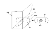
- the receiving seat 409 is formed with a circular hole 409b penetrating in the vehicle width direction.
- a circular hole 409b penetrating in the vehicle width direction is formed by moving the end mill in the vehicle width direction while rotating the substantially cylindrical end mill about an axis extending in the vehicle width direction.
- the nut housing space V4 is an internal space of the circular hole 409b. Therefore, the nut housing space V4 is formed by an arc-shaped surface and is a cylindrical space.
- a cylindrical nut 472 is housed from one side in the vehicle width direction.
- the nut 472 is formed with a screw hole 472a having a female screw threadedly engaged with the male screw of the bolt 71 on the inner peripheral surface.
- the fastening surface 472b of the nut 472 has the same arc shape as the first surface S41 that forms the nut housing space V4.
- the nut is arranged such that the shortest distance between the third surface S43 of the receiving seat 409 forming the nut housing space V4 and the axis J1 of the bolt 71 is smaller than the maximum radius of the nut 472 when viewed from the direction of the axis J1. 472 is accommodated in the nut accommodating space V4.
- region A which opposes the nut 472 of 1st surface S41 which forms the nut accommodation space V4 is the same circular arc shape as the fastening surface 472b of the nut 472, it is the bolt 71 and the nut 72.
- the nut 72 can be brought into surface contact with the first surface S41 without using the spacer 11 at the time of fastening, and the number of parts can also be reduced.
- the shortest distance between the third surface S43 of the receiving seat 409 and the axis J1 of the bolt 71 is smaller than the maximum radius of the nut 472, even if the nut 472 rotates around the axis J1, the maximum radius is rotated.
- the third surface S43 of the receiving seat 409 is positioned as an obstacle wall on the rotation locus of the nut 472 having a radius. Therefore, it is possible to prevent the nut 472 from coming into contact with the third surface S43 of the receiving seat 409 at the time of fastening with the bolt 71 and the nut 472 to rotate together.
- the nut housing space V4 is an internal space of the circular hole 409b, and is provided in the receiving seat 409 as a cylindrical space. Since the circular hole 409b is formed by moving the substantially cylindrical end mill in the vehicle width direction while rotating, a configuration is provided in which a square hole is formed in the receiving seat and the internal space of the square hole is used as a nut housing space. In comparison, the nut housing space V4 can be easily formed in the receiving seat 409.
- a one-link traction device 500 for a rail vehicle trolley according to a fifth embodiment is obtained by partially modifying the receiving seat 9 and the spacer 11 according to the first embodiment.
- the receiving seat 509 and the spacer 511 according to the fifth embodiment will be described focusing on differences from the first embodiment.
- FIG. 13 is a view corresponding to FIG. 2 of a one-link traction device 500 for a rail vehicle dolly according to a fifth embodiment.
- FIG. 14 is a view corresponding to FIG. 5 of the one-link traction device 500 of the rail vehicle bogie according to the fifth embodiment.
- the receiving seat 509 is formed with a square hole 509 b penetrating in the vehicle width direction.
- the nut housing space V5 is an internal space of the square hole 509b.
- the nut housing space V5 includes a first surface S51 and a second surface S52 that face the nut 72 in the direction of the axis J1 of the bolt 71, and a third surface that faces the nut 72 in a direction perpendicular to the axis J1 of the bolt 71.
- the surface S53 is formed.
- 1st surface S51 has a plane part parallel to the fastening surface 72b of the nut 72 seeing from the vehicle width direction, and the circular arc surface part located in the upper and lower sides of the said plane part. Further, the nut 72 is accommodated in the nut accommodating space V5 so that the shortest distance connecting the third surface S53 and the axis J1 is larger than the maximum radius R of the nut 72.
- a spacer 511 is accommodated in the nut accommodation space V5.
- the spacer 511 is a concave member.
- the spacer 511 includes a sandwiching portion 512 sandwiched between the first surface S51 and the fastening surface 72b of the nut 72, and extending portions 513 and 514 extending from the both ends in the vertical direction of the sandwiching portion 512 toward the second surface S52. And have.
- the vertical dimension of the clamping part 512 is larger than the maximum diameter of the nut 72.
- a surface 512a on the first surface S51 side of the sandwiching portion 512 has a shape parallel to the first surface S51 when viewed from the vehicle width direction. Further, the surface 512 a on the first surface S 51 side of the sandwiching part 512 has a larger area than the fastening surface 72 b of the nut 72.
- the surface 512b on the fastening surface 72b side of the clamping part 512 has the same planar shape as the fastening surface 72b.
- the extending portions 513 and 514 are opposed to the nut 72 with a gap in the vertical direction. That is, the lower surface 513a of the extending portion 513 and the upper surface 514a of the extending portion 514 are opposed to the nut 72 in a direction orthogonal to the axis J1.
- the lower surface 513a of the extending portion 513 and the upper surface 514a of the extending portion 514 are referred to as nut-facing surfaces.
- the shortest distance between the nut facing surfaces 513a, 514a and the axis J1 of the bolt 71 is set to be smaller than the maximum radius R of the nut 72 when viewed from the direction of the axis J1.
- the nut 72 is accommodated in the nut accommodating space V5 so that the shortest distance connecting the third surface S53 and the axis J1 is larger than the maximum radius R of the nut 72.
- the spacer 511 includes nut facing surfaces 513a and 514a in the extending portions 513 and 514 extending from both ends of the holding portion 512 in the vertical direction.
- bolt 71 is set so that it may become smaller than the largest radius R of the nut 72 seeing from an axis line J1 direction.
- the nut facing surfaces 513a and 514a of the spacer 511 are on the obstacle wall on the rotation locus of the nut 72 having the maximum radius R as the rotation radius. Will be located. Therefore, it is possible to prevent the nut 72 from coming into contact with the nut facing surfaces 513a and 514a when the bolt 71 is fastened, and the nut 72 rotating together.
- the nut 72 when the nut 71 is fastened to the bolt 71, the nut 72 abuts against the third surface S ⁇ b> 3 of the receiving seat 9 to prevent the nut 72 from rotating together.
- the vertical dimension of 11 b is substantially equal to the vertical dimension of the fastening surface 72 b of the nut 72.
- the surface 11 b of the spacer 11 and the second of the receiving seat 9 are prevented.
- the strength is designed so that the surface pressure acting on each surface S1 is not more than the limit surface pressure of each material forming the spacer 11 and the receiving seat 9.
- a washer spacer according to an industrial standard (JIS standard or the like) has a size larger than a fastening surface of a nut, and the seating area of the washer is also defined in the industrial standard.
- the spacer 11 has a shape that has the same vertical dimension as the fastening surface 72b of the nut 72, and the seating area of the spacer 11 may be smaller than the seating area of the washer specified by the industry standard. There is. Therefore, in calculating the surface pressure acting on the spacer 11 and the receiving seat 9, the seating area of the washer stipulated by the industry standard cannot be used.
- the nut 72 is in contact with the nut facing surfaces 513a and 514a of the spacer 511 to prevent the nut 72 from rotating together.
- the vertical dimension of the surface 512a of the spacer 511 is determined by the fastening of the nut 72. It is larger than the vertical dimension of the surface 72b.
- the surface pressure acting on the spacer 511 and the receiving seat 509 is calculated using the seating surface area of the washer specified by the industry standard, and the surface pressure is calculated by the spacer 511. And if it confirms that it is below the limit surface pressure of each material which forms the receiving seat 509, it will evaluate with sufficient intensity
- a traction device 600 of a cart 605 according to the sixth embodiment is a partial modification of the traction device 500 according to the fifth embodiment.
- the traction device 600 according to the sixth embodiment will be described focusing on differences from the fifth embodiment.
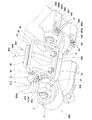
- FIG. 15 is a perspective view of the traction device 600 according to the sixth embodiment when viewed obliquely from below.
- 16 is an exploded perspective view of a part of the fixing structure of the link member 2 and the receiving seats 608 and 609 in the traction device 600 shown in FIG.
- the regulating member 30 is fixed to the center pin 604 with a plurality of bolts 41.
- the regulating member 30 is a member that regulates an abnormal rise of the vehicle body 603 due to expansion of an air spring (not shown).
- the restricting member 30 includes a fixed portion 31 fixed to the receiving seat 608 of the center pin 604 and a contact portion 32 that protrudes outward from the fixed portion 31 in the vehicle width direction.
- the fixing portion 31 has a substantially flat plate shape, and includes a locking portion 31a for locking from above the groove portion 608c formed by recessing the upper surface of the receiving seat 608 downward. Since the locking portion 31 a is locked to the groove portion 608 c, the regulating member 30 is temporarily fixed to the center pin 604 before being fixed with the bolt 41.
- the abutting portion 32 has a substantially flat plate shape, and a resin material 34 is provided on the upper surface via a metal plate 33. When the air spring expands more than a predetermined amount, the resin material 34 comes into contact with the carriage frame 606, so that the abnormal rise of the vehicle body 603 is restricted.
- the spacers 611 and 621 are fixed to the receiving seats 608 and 609 by the second fastening member including the spacer fixing bolt 51. Further, the spacer 611 inserted into the nut receiving space V61 of the receiving seat 608 and the spacer 621 inserted into the nut receiving space V62 of the receiving seat 609 have different shapes and insertion directions.
- Receiving seats 608 and 609 have screw holes 608d and 609d, respectively, in which female screws to be engaged with male screws of the spacer fixing bolt 51 are formed.
- the screw hole 608d is provided above the nut housing space V61 in the side surface 608e on the outer side in the vehicle width direction of the receiving seat 608, and extends in the vehicle width direction.
- the screw hole 608d is provided below the groove 608c.
- the screw hole 609d is provided on the mandrel 21b side of the lower surface 609c of the receiving seat 609 with respect to the nut housing space V62, and extends in the vertical direction.
- the connecting portion 693 is a wall portion that is located on both sides of the nut 72 in the vehicle width direction and forms the nut accommodating space V62.
- the spacer 611 is inserted into the nut receiving space V61 of the receiving seat 608 from the outside in the vehicle width direction.
- the spacer 611 has a spacer main body 612 accommodated in the nut accommodating space V61 and a flange 613 projecting from the spacer main body 612 to the outside of the nut accommodating space V61.
- the spacer main body 612 includes a sandwiching portion 512 and a pair of upper and lower extending portions 513 and 514.
- the flange portion 613 protrudes upward from an end portion on the outer side in the vehicle width direction of the spacer body portion 612, and extends along the side surface 608e on the outer side in the vehicle width direction of the receiving seat 608.
- the flange portion 613 is formed with a second insertion hole 613a through which the spacer fixing bolt 51 is inserted and a screw hole 613b provided below the second insertion hole 613a.
- the second insertion hole 613 a is a drill hole, and is a long hole having a diameter in the longitudinal direction larger than the diameter of the spacer fixing bolt 51.
- the spacer 611 is fixed to the receiving seat 608 through the second insertion hole 613a by the spacer fixing bolt 51.
- a screw hole 613b is used to facilitate removal of the spacer 611. Specifically, the flange 613 moves in a direction away from the receiving seat 608 by rotating the screw in a state where the tip end portion of the screw screwed into the screw hole 613b is pressed against the side surface 608e of the receiving seat 608.
- the nut housing space V62 is an internal space of a square hole 609b extending in the vertical direction, and is recessed in the lower surface 609c of the receiving seat 609.
- the spacer 621 is inserted from below into the nut housing space V62.
- the spacer 621 includes a spacer main body portion 622 accommodated in the nut accommodating space V62 and a flange portion 623 protruding from the spacer main body portion 622 to the outside of the nut accommodating space V62.
- the spacer main body 622 is sandwiched between the first surface S61 of the receiving seat 609 and the fastening surface 72b of the nut 72, and from both the left and right ends of the sandwiching portion 641 toward the second surface S62 of the receiving seat 609. And a pair of left and right extending portions 642 and 643 extending in the direction.
- the holding portion 641 is formed with a first insertion hole 641a through which the bolt 71 is inserted.
- the flange portion 623 protrudes from the lower end portion of the spacer main body portion 622 toward the mandrel 21b, and is along the lower surface 609c of the receiving seat 609.
- the flange portion 623 is formed with two second insertion holes 623a through which the spacer fixing bolts 51 are inserted, and screw holes 623b provided between the two second insertion holes 623a.
- the second insertion hole 623 a is a drill hole, and is a long hole having a diameter in the longitudinal direction larger than the diameter of the spacer fixing bolt 51.
- the screw hole 623b has the same function as the screw hole 613b, and is used as needed when the spacer 621 is removed from the seat 609.
- the other configuration is the same as that of the fifth embodiment.
- the sixth embodiment since the spacers 611 and 621 are fixed to the receiving seats 608 and 609 by the spacer fixing bolts 51, the spacers 611 and 621 before and after removing the bolt 71 and the nut 72 during maintenance or the like. Can be kept in the same place, and the spacers 611 and 621 can be prevented from falling.
- the screw hole 608d extends in the vehicle width direction below the groove portion 608c formed on the upper surface of the receiving seat 608, so that the spacer fixing bolt 51 inserted through the screw hole 608d is The spacer 611 can be fixed to the seat 608 while preventing interference with the locking portion 31a of the regulating member 30 locked to the groove portion 608c.
- the nut housing space V62 is a wall portion that is recessed in the lower surface 609c of the receiving seat 609, and the connecting portions 693 are positioned on both sides of the nut 72 in the vehicle width direction to form the nut housing space V62. Accordingly, when a load in the vehicle longitudinal direction acts on the receiving seat 609, the cross section perpendicular to the vehicle longitudinal direction of the receiving seat 609 changes compared to the configuration in which the nut housing space penetrates the receiving seat in the vehicle width direction. Generation of a large stress in the portion can be suppressed, and the strength of the entire receiving seat 609 can be ensured.
- a load in the longitudinal direction of the vehicle such as a driving force or a braking force of the carriage 605 is transmitted from the receiving seat 609 of the carriage frame 606 of the carriage 605 to the vehicle body 603 via the link member 2 and the receiving seat 608.
- the load acting on 609 is large. Therefore, in order to secure the strength of the receiving seat 609 of the carriage frame 606, the configuration of the present embodiment is effective.
- a cart traction device 700 according to the seventh embodiment is obtained by partially modifying the receiving seat 309 according to the third embodiment.
- the receiving seat 709 according to the seventh embodiment will be described focusing on differences from the third embodiment.
- FIG. 17 is a view corresponding to FIG. 9 of the traction device 700 according to the seventh embodiment.
- a spacer 711 is inserted from below into the nut housing space V ⁇ b> 7 of the receiving seat 709 together with the nut 72.
- the spacer 711 is fixed to the receiving seat 709 by a second fastening member including the spacer fixing bolt 51.
- the receiving seat 709 has a screw hole 709d in which a female screw to be screwed with the male screw of the spacer fixing bolt 51 is formed.
- the screw hole 709d is provided on the mandrel 21b (see FIG. 1) side of the lower surface 709c of the receiving seat 709 with respect to the nut housing space V7.
- the screw holes 709d are provided on both sides of the insertion hole 709a in the vehicle width direction.
- the spacer 711 has a substantially flat spacer main body 712 accommodated in the nut accommodating space V7 and a flange 713 protruding from the spacer main body 712 to the outside of the nut accommodating space V7.
- the spacer main body 712 is formed with a first insertion hole 712a through which the bolt 71 is inserted.
- the spacer main body 712 is sandwiched between the receiving seat 709 and the nut 72 in the nut housing space V7.
- a surface 712b on the receiving seat 709 side of the spacer main body 712 has a shape having a flat surface portion and circular arc surface portions provided on the left and right sides of the flat surface portion.
- the surface 712c on the nut 72 side of the spacer main body 712 has the same planar shape as the fastening surface 72b.
- the flange portion 713 protrudes from the lower end portion of the spacer main body portion 712 toward the mandrel 21b side, and extends along the lower surface 709c of the receiving seat 709.
- the flange portion 713 is formed with a pair of second insertion holes 713a through which the spacer fixing bolts 51 are inserted.
- the second insertion hole 713 a is a drill hole, and is a long hole having a diameter in the longitudinal direction larger than the diameter of the spacer fixing bolt 51.
- the spacer 711 is fixed to the receiving seat 709 by the spacer fixing bolt 51, the spacer 711 can be kept in the same place before and after removing the bolt 71 and the nut 72 during maintenance, etc. The loss of the spacer 711 can be prevented.
- the present invention is not limited to the above-described embodiment, and the configuration can be changed, added, or deleted without departing from the spirit of the present invention.
- the center pin 4 604 and the carriage seats 6, 608, 9, and 609 of the bogie frame 6 606 are also connected to the mandrel 21 b of the link member 2 by the first fastening member 7 having the bolt 71 and the nut 72.
- the present invention is not limited to this. Any one of the receiving seats 8, 608, 9, 609 of the center pin 4, 604 or the bogie frame 6, 606 is connected to the link member 2 by the first fastening member 7. It may be fixed to the mandrel 21b.
- the nuts 72 and 472 are hexagonal nuts or columnar nuts. However, the nuts 72 and 472 are not limited to this, and may be square nuts having a rectangular outer shape, for example.
Landscapes
- Engineering & Computer Science (AREA)
- Mechanical Engineering (AREA)
- Seats For Vehicles (AREA)
- Connection Of Plates (AREA)
- Body Structure For Vehicles (AREA)
Abstract
Description
図1は、本実施形態に係る軌条車両用台車5を備えた軌条車両10における1本リンク式牽引装置1周辺の側面図である。図1に示すように、軌条車両10は、車体3と、車体3を支持する軌条車両用台車5(以下、台車5と呼ぶ。)と、を備えている。車体3の枕はり3aの下面には、中心ピン4がボルト15によって固定されている。台車5は枕はりを備えていない、いわゆるボルスタレス式台車である。車体3は、台車5の1本リンク式牽引装置1を介して、台車枠6と結合されている。
第2実施形態に係る軌条車両用台車の1本リンク式牽引装置200は、第1実施形態に係る受け座9を一部変形したものである。以下では、第2実施形態に係る受け座209について、第1実施形態と異なる点を中心に説明する。
第3実施形態に係る軌条車両用台車の1本リンク式牽引装置300は、第1実施形態に係る受け座9を一部変形したものである。以下では、第3実施形態に係る受け座309について、第1実施形態と異なる点を中心に説明する。
第4実施形態に係る軌条車両用台車の1本リンク式牽引装置400は、第1実施形態に係る受け座9、ナット72を一部変形したものである。以下では、第4実施形態に係る受け座409、ナット472について、第1実施形態と異なる点を中心に説明する。
第5実施形態に係る軌条車両用台車の1本リンク式牽引装置500は、第1実施形態に係る受け座9,スペーサ11を一部変形したものである。以下では、第5実施形態に係る受け座509,スペーサ511について、第1実施形態と異なる点を中心に説明する。
第6実施形態に係る台車605の牽引装置600は、第5実施形態に係る牽引装置500を一部変形したものである。以下では、第6実施形態に係る牽引装置600について、第5実施形態と異なる点を中心に説明する。
第7実施形態に係る台車の牽引装置700は、第3実施形態に係る受け座309を一部変形したものである。以下では、第7実施形態に係る受け座709について、第3実施形態と異なる点を中心に説明する。
2 リンク部材
3,603 車体
4,604 中心ピン(固定対象物)
5,605 軌条車両用台車
6,606 台車枠(固定対象物)
7 第1締結部材
8,608 受け座
9,209,309,409,509,609,709 受け座
9a,709a 挿通孔
309c,609c 下面
609d,709d ネジ孔
10 軌条車両
11,511,611,621,711 スペーサ
11a,712a 第1挿通孔
51 スペーサ固定用ボルト(第2締結部材)
71 ボルト
72,472 ナット
72b,472b 締結面
90 基部
91 第1突出部
92 第2突出部
93,393,693 連結部
513a,514a ナット対向面
608f,709f ネジ孔
612,622,712 スペーサ本体部
613,623,713 フランジ部
613a,623a,713a 第2挿通孔
J1 軸線
S1,S21,S31,S41,S51,S61 第1面
S2,S22,S32,S52,S62 第2面
S3,S32,S33,S43 第3面
V1,V2,V3,V4,V5,V61,V62,V7 ナット収容空間
Claims (8)
- 台車枠と、
前記台車枠と車体とを結合し、前記台車枠に作用する力を前記車体に伝達する1本リンク式牽引装置と、を備え、
前記1本リンク式牽引装置は、
前記車体の中心ピンと前記台車枠とを連結し、車両長手方向に延びる単一のリンク部材と、
前記中心ピン又は前記台車枠からなる固定対象物に設けられ、前記リンク部材が固定される受け座と、
前記リンク部材の端部及び前記受け座に車両長手方向一方側から挿通されるボルトと、前記ボルトに車両長手方向他方側から螺合するナットとを含み、前記リンク部材の前記端部を前記受け座に固定する第1締結部材と、を有し、
前記受け座には、前記ボルトが挿通される挿通孔と、前記挿通孔と連通して前記ナットが収容されるナット収容空間とが形成されている、軌条車両用台車。 - 前記受け座は、
前記固定対象物に接合された基部と、
前記ナットの前記車両長手方向一方側に位置して前記ナット収容空間を形成する第1面を含み、前記基部から突出し、前記挿通孔が形成される第1突出部と、
前記ナットの前記車両長手方向他方側に位置して前記ナット収容空間を形成する第2面を含み、前記基部から突出する第2突出部と、
前記第1突出部と前記第2突出部とを少なくとも前記ボルトの軸線よりも前記第1突出部の突出端側にて連結する連結部と、を有する、請求項1に記載の軌条車両用台車。 - 前記ナット収容空間は、前記受け座の下面に凹設され、
前記連結部は、前記ナットの車幅方向両側に位置して前記ナット収容空間を形成する壁部である、請求項2に記載の軌条車両用台車。 - 前記受け座は、前記ナットに対して前記ボルトの軸線に直交する方向に対向して前記ナット収容空間を形成する第3面を含み、
前記第3面と前記軸線との間の最短距離は、前記ナットの最大半径よりも小さい、請求項1乃至3のいずれか1項に記載の軌条車両用台車。 - 前記1本リンク式牽引装置は、前記第1面と前記ナットの締結面との間に挟まれ、前記ボルトが挿通される第1挿通孔が形成されたスペーサを更に有し、
前記第1面の前記締結面と対向する対向領域は、前記締結面と異なる形状であり、
前記スペーサの前記第1面側の面は、前記第1面の前記対向領域と同一形状を有し、
前記スペーサの前記締結面側の面は、前記締結面と同一形状を有する、請求項1乃至4のいずれか1項に記載の軌条車両用台車。 - 前記1本リンク式牽引装置は、前記第1面と前記ナットの締結面との間に挟まれ、前記ボルトが挿通される第1挿通孔が形成されたスペーサを更に有し、
前記スペーサは、前記ナットに対して前記ボルトの軸線に直交する方向に対向するナット対向面を含み、
前記ナット対向面と前記軸線との間の最短距離は、前記ナットの最大半径よりも小さい、請求項1乃至4のいずれか1項に記載の軌条車両用台車。 - 前記1本リンク式牽引装置は、前記スペーサを前記受け座に固定するスペーサ固定用ボルトからなる第2締結部材を更に有し、
前記スペーサは、前記ナット収容空間に収容されるスペーサ本体部と、前記スペーサ本体部から前記ナット収容空間の外部に突出して前記受け座の外面に沿うフランジ部とを有し、
前記フランジ部には、前記スペーサ固定用ボルトが挿通される第2挿通孔が形成され、
前記受け座は、前記スペーサ固定用ボルトの雄ネジと螺合する雌ネジが形成されたネジ孔を有する、請求項5又は6に記載の軌条車両用台車。 - 請求項1乃至7のいずれか1項に記載の軌条車両用台車を備えた、軌条車両。
Priority Applications (4)
| Application Number | Priority Date | Filing Date | Title |
|---|---|---|---|
| US15/577,107 US10793167B2 (en) | 2015-05-25 | 2016-05-24 | Railcar bogie and railcar including same |
| SG11201709659VA SG11201709659VA (en) | 2015-05-25 | 2016-05-24 | Railcar bogie and railcar including same |
| CN201680026598.9A CN107531255B (zh) | 2015-05-25 | 2016-05-24 | 轨道车辆用转向架及具备该轨道车辆用转向架的轨道车辆 |
| JP2017520234A JP6499755B2 (ja) | 2015-05-25 | 2016-05-24 | 軌条車両用台車及びそれを備えた軌条車両 |
Applications Claiming Priority (2)
| Application Number | Priority Date | Filing Date | Title |
|---|---|---|---|
| JP2015105486 | 2015-05-25 | ||
| JP2015-105486 | 2015-05-25 |
Publications (1)
| Publication Number | Publication Date |
|---|---|
| WO2016189854A1 true WO2016189854A1 (ja) | 2016-12-01 |
Family
ID=57394118
Family Applications (1)
| Application Number | Title | Priority Date | Filing Date |
|---|---|---|---|
| PCT/JP2016/002500 Ceased WO2016189854A1 (ja) | 2015-05-25 | 2016-05-24 | 軌条車両用台車及びそれを備えた軌条車両 |
Country Status (5)
| Country | Link |
|---|---|
| US (1) | US10793167B2 (ja) |
| JP (1) | JP6499755B2 (ja) |
| CN (1) | CN107531255B (ja) |
| SG (1) | SG11201709659VA (ja) |
| WO (1) | WO2016189854A1 (ja) |
Citations (3)
| Publication number | Priority date | Publication date | Assignee | Title |
|---|---|---|---|---|
| JPH036539Y2 (ja) * | 1986-11-04 | 1991-02-19 | ||
| JPH1178455A (ja) * | 1997-09-17 | 1999-03-23 | Yamakawa Ind Co Ltd | サスペンションリンク |
| JP2010285071A (ja) * | 2009-06-11 | 2010-12-24 | Tokyu Car Corp | 鉄道車両用台車 |
Family Cites Families (11)
| Publication number | Priority date | Publication date | Assignee | Title |
|---|---|---|---|---|
| US2934028A (en) * | 1957-05-22 | 1960-04-26 | Gen Steel Castings Corp | Railway vehicle structure |
| US3402679A (en) * | 1965-10-23 | 1968-09-24 | Pullman Inc | Railway car trucks |
| US4134343A (en) * | 1976-09-27 | 1979-01-16 | General Steel Industries, Inc. | Radial axle railway truck |
| JPS636539U (ja) * | 1986-06-27 | 1988-01-16 | ||
| CN101480960A (zh) * | 2009-02-26 | 2009-07-15 | 齐齐哈尔轨道交通装备有限责任公司 | 一种纵向牵引装置及带有该纵向牵引装置的转向架 |
| CN202294828U (zh) * | 2011-10-28 | 2012-07-04 | 长春轨道客车股份有限公司 | 客室侧顶板防松定位装置 |
| EP2783939B1 (en) | 2011-12-23 | 2017-03-29 | CRRC Shandong Co., Ltd. | High speed railway vehicle bogie |
| CN102490753B (zh) * | 2011-12-23 | 2017-06-09 | 中车山东机车车辆有限公司 | 铁路货车转向架的牵引拉杆装置 |
| CN202541565U (zh) * | 2012-05-03 | 2012-11-21 | 济南轨道交通装备有限责任公司 | 快速铁路货车转向架弹性吊杆系统 |
| JP5854961B2 (ja) * | 2012-09-26 | 2016-02-09 | 公益財団法人鉄道総合技術研究所 | 連結装置の評価装置とその評価プログラム |
| CN104554307A (zh) * | 2014-12-18 | 2015-04-29 | 南车青岛四方机车车辆股份有限公司 | 动车组车体及其内风挡安装结构 |
-
2016
- 2016-05-24 CN CN201680026598.9A patent/CN107531255B/zh active Active
- 2016-05-24 WO PCT/JP2016/002500 patent/WO2016189854A1/ja not_active Ceased
- 2016-05-24 SG SG11201709659VA patent/SG11201709659VA/en unknown
- 2016-05-24 JP JP2017520234A patent/JP6499755B2/ja active Active
- 2016-05-24 US US15/577,107 patent/US10793167B2/en active Active
Patent Citations (3)
| Publication number | Priority date | Publication date | Assignee | Title |
|---|---|---|---|---|
| JPH036539Y2 (ja) * | 1986-11-04 | 1991-02-19 | ||
| JPH1178455A (ja) * | 1997-09-17 | 1999-03-23 | Yamakawa Ind Co Ltd | サスペンションリンク |
| JP2010285071A (ja) * | 2009-06-11 | 2010-12-24 | Tokyu Car Corp | 鉄道車両用台車 |
Also Published As
| Publication number | Publication date |
|---|---|
| US20180201281A1 (en) | 2018-07-19 |
| CN107531255B (zh) | 2020-01-03 |
| JP6499755B2 (ja) | 2019-04-10 |
| US10793167B2 (en) | 2020-10-06 |
| JPWO2016189854A1 (ja) | 2017-12-14 |
| SG11201709659VA (en) | 2017-12-28 |
| CN107531255A (zh) | 2018-01-02 |
Similar Documents
| Publication | Publication Date | Title |
|---|---|---|
| CN105392598B (zh) | 用于安装紧固件的工具 | |
| US20070210674A1 (en) | Stator of rotating electric machine and structure thereof | |
| JP2017503663A (ja) | マウンティングアセンブリ | |
| JP2010184684A (ja) | 鉄道車両用軸箱支持装置 | |
| EP1642799A2 (en) | Axle box suspension for railway vehicle | |
| US20150096849A1 (en) | Brake Carrier Mounting Arrangement | |
| WO2021257477A1 (en) | Torque rod press tools, systems, and methods | |
| US9239070B2 (en) | Bolt mount system | |
| JP6499755B2 (ja) | 軌条車両用台車及びそれを備えた軌条車両 | |
| CN101910652A (zh) | 用于套置并与螺栓啮合的啮合单元 | |
| JP2010143399A (ja) | サイドメンバのナット保持構造 | |
| JP4841493B2 (ja) | ねじ類の締付工具 | |
| JP2006300331A (ja) | 垂直搭載エアディスクブレーキキャリパー組立体 | |
| JP2018091425A (ja) | 取付金具及び防鳥ネット取付具 | |
| US7354217B2 (en) | Fastening device and method for attaching an object to a support structure | |
| US20190184803A1 (en) | Component mount and chassis incorporating same | |
| JP6844360B2 (ja) | 電池モジュール | |
| CN106660420B (zh) | 用于将轴颈可逆地固定在拉杆轴处的系统和方法 | |
| JP2020156279A (ja) | 回転電機 | |
| US7798575B1 (en) | Hub and drum assembly including recessed shipping nut | |
| JP3263385B2 (ja) | 舌付き座金回り止め治具 | |
| US11213924B2 (en) | Stuck axle hub removal assembly | |
| JP6576168B2 (ja) | ブレース連結金具 | |
| JP3140190U (ja) | カップリング | |
| JP2012066360A (ja) | ボルト締め付け用ソケット |
Legal Events
| Date | Code | Title | Description |
|---|---|---|---|
| 121 | Ep: the epo has been informed by wipo that ep was designated in this application |
Ref document number: 16799567 Country of ref document: EP Kind code of ref document: A1 |
|
| ENP | Entry into the national phase |
Ref document number: 2017520234 Country of ref document: JP Kind code of ref document: A |
|
| WWE | Wipo information: entry into national phase |
Ref document number: 11201709659V Country of ref document: SG |
|
| WWE | Wipo information: entry into national phase |
Ref document number: 15577107 Country of ref document: US |
|
| NENP | Non-entry into the national phase |
Ref country code: DE |
|
| 122 | Ep: pct application non-entry in european phase |
Ref document number: 16799567 Country of ref document: EP Kind code of ref document: A1 |