US3402679A - Railway car trucks - Google Patents
Railway car trucks Download PDFInfo
- Publication number
- US3402679A US3402679A US502840A US50284065A US3402679A US 3402679 A US3402679 A US 3402679A US 502840 A US502840 A US 502840A US 50284065 A US50284065 A US 50284065A US 3402679 A US3402679 A US 3402679A
- Authority
- US
- United States
- Prior art keywords
- truck
- side frame
- vehicle body
- transoms
- resilient
- Prior art date
- Legal status (The legal status is an assumption and is not a legal conclusion. Google has not performed a legal analysis and makes no representation as to the accuracy of the status listed.)
- Expired - Lifetime
Links
- 230000000712 assembly Effects 0.000 description 13
- 238000000429 assembly Methods 0.000 description 13
- NJPPVKZQTLUDBO-UHFFFAOYSA-N novaluron Chemical compound C1=C(Cl)C(OC(F)(F)C(OC(F)(F)F)F)=CC=C1NC(=O)NC(=O)C1=C(F)C=CC=C1F NJPPVKZQTLUDBO-UHFFFAOYSA-N 0.000 description 10
- 238000006073 displacement reaction Methods 0.000 description 5
- 230000035939 shock Effects 0.000 description 4
- 239000006096 absorbing agent Substances 0.000 description 3
- 230000000295 complement effect Effects 0.000 description 3
- 238000010276 construction Methods 0.000 description 3
- 239000012530 fluid Substances 0.000 description 3
- 230000000452 restraining effect Effects 0.000 description 3
- 230000006835 compression Effects 0.000 description 2
- 238000007906 compression Methods 0.000 description 2
- 239000000428 dust Substances 0.000 description 2
- 239000002184 metal Substances 0.000 description 2
- 238000000926 separation method Methods 0.000 description 2
- 238000003466 welding Methods 0.000 description 2
- 238000005266 casting Methods 0.000 description 1
- 238000012217 deletion Methods 0.000 description 1
- 230000037430 deletion Effects 0.000 description 1
- 238000003780 insertion Methods 0.000 description 1
- 230000037431 insertion Effects 0.000 description 1
- 238000012986 modification Methods 0.000 description 1
- 230000004048 modification Effects 0.000 description 1
- 230000001105 regulatory effect Effects 0.000 description 1
- 125000006850 spacer group Chemical group 0.000 description 1
Images


Classifications
-
- B—PERFORMING OPERATIONS; TRANSPORTING
- B61—RAILWAYS
- B61F—RAIL VEHICLE SUSPENSIONS, e.g. UNDERFRAMES, BOGIES OR ARRANGEMENTS OF WHEEL AXLES; RAIL VEHICLES FOR USE ON TRACKS OF DIFFERENT WIDTH; PREVENTING DERAILING OF RAIL VEHICLES; WHEEL GUARDS, OBSTRUCTION REMOVERS OR THE LIKE FOR RAIL VEHICLES
- B61F5/00—Constructional details of bogies; Connections between bogies and vehicle underframes; Arrangements or devices for adjusting or allowing self-adjustment of wheel axles or bogies when rounding curves
- B61F5/02—Arrangements permitting limited transverse relative movements between vehicle underframe or bolster and bogie; Connections between underframes and bogies
- B61F5/14—Side bearings
- B61F5/144—Side bearings comprising fluid damping devices
-
- B—PERFORMING OPERATIONS; TRANSPORTING
- B61—RAILWAYS
- B61F—RAIL VEHICLE SUSPENSIONS, e.g. UNDERFRAMES, BOGIES OR ARRANGEMENTS OF WHEEL AXLES; RAIL VEHICLES FOR USE ON TRACKS OF DIFFERENT WIDTH; PREVENTING DERAILING OF RAIL VEHICLES; WHEEL GUARDS, OBSTRUCTION REMOVERS OR THE LIKE FOR RAIL VEHICLES
- B61F3/00—Types of bogies
- B61F3/02—Types of bogies with more than one axle
- B61F3/08—Types of bogies with more than one axle without driven axles or wheels
-
- B—PERFORMING OPERATIONS; TRANSPORTING
- B61—RAILWAYS
- B61F—RAIL VEHICLE SUSPENSIONS, e.g. UNDERFRAMES, BOGIES OR ARRANGEMENTS OF WHEEL AXLES; RAIL VEHICLES FOR USE ON TRACKS OF DIFFERENT WIDTH; PREVENTING DERAILING OF RAIL VEHICLES; WHEEL GUARDS, OBSTRUCTION REMOVERS OR THE LIKE FOR RAIL VEHICLES
- B61F5/00—Constructional details of bogies; Connections between bogies and vehicle underframes; Arrangements or devices for adjusting or allowing self-adjustment of wheel axles or bogies when rounding curves
- B61F5/26—Mounting or securing axle-boxes in vehicle or bogie underframes
- B61F5/30—Axle-boxes mounted for movement under spring control in vehicle or bogie underframes
- B61F5/32—Guides, e.g. plates, for axle-boxes
-
- B—PERFORMING OPERATIONS; TRANSPORTING
- B61—RAILWAYS
- B61F—RAIL VEHICLE SUSPENSIONS, e.g. UNDERFRAMES, BOGIES OR ARRANGEMENTS OF WHEEL AXLES; RAIL VEHICLES FOR USE ON TRACKS OF DIFFERENT WIDTH; PREVENTING DERAILING OF RAIL VEHICLES; WHEEL GUARDS, OBSTRUCTION REMOVERS OR THE LIKE FOR RAIL VEHICLES
- B61F5/00—Constructional details of bogies; Connections between bogies and vehicle underframes; Arrangements or devices for adjusting or allowing self-adjustment of wheel axles or bogies when rounding curves
- B61F5/50—Other details
- B61F5/52—Bogie frames
Definitions
- a railway vehicle truck for direct connection to a transit vehicle body including a pair of oppositely disposed side frames, each frame having a transversely extending transom and connecting means pivotally connecting the free end of each transom to the opposite frame with the transoms being longitudinally spaced from each other so that the frames are pivotal relative to each other about a diagonal axis extending through the connecting means;
- the side frames are supported by a pair of longitudinally spaced and transversely extending wheel and axle assemblies which are attached to the side frames by journal box assemblies having resilient means whereby the wheel and axle assemblies have relatively greater movement vertically than longitudinally.
- the present invention relates to railway vehicle trucks and in particular to .a lightweight railway vehicle truck for use with transit railway vehicles.
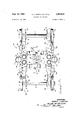
- FIG. 1 is a fragmentary side elevational view of a transit vehicle body mounted on a railway vehicle truck embodying the principles of the present invention
- FIG. 2 is .an enlarged side elevational view showing the railway vehicle truck of the present invention mounted on the underside of a transit vehicle body;
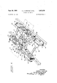
- FIG. 3 is a top plan view of the railway vehicle truck
- FIG. 4 is a perspective view of the railway vehicle truck and showing in phantom the connecting plates on the underside of the railway transit vehicle;
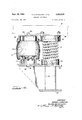
- FIG. 5 is across-sectional view taken generally along the lines of 5-5 of FIG. 3 and showing the arrangement for connecting the railway vehicle truck directly to the underside of the transit vehicle body;
- FIG. 6 is .a perspective view of the railway vehicle truck similar to FIG. 5;
- FIG. 7 is a view taken generally along the lines 77 of FIG. 3 and showing in particular one of the side frame stems extending between and connecting the two laterally spaced side frames of the track;
- FIG. 8 is a top plan view of the hanger means used to connect the truck directly to the underside of the vehicle body;
- FIG. 9 is a cross sectional view taken generally along the lines of 9-9 of FIG. 5 and showing in particular an end elevational view of the hanger;
- FIG. 10 is a cross sectional view taken through the connection of the stem of one of the side frames to the opposite one of the side frames;
- FIG. 11 is a view taken generally along the lines 11-11 of FIG. 7 and showing in particular the connection of the leveling valve between the transit vehicle body and the truck;
- FIG. 12 is a view taken generally along lines 12-12 of FIG. 3 and showing in particular the connection of the vehicle body springs and the air spring to the truck frame and the underside of the railway car;
- FIG. 13 is a fragmentary top plan view of the journal box arrangement seated within the side frame;
- FIG. 14 is a fragmentary front elevational view of the journal box arrangement illustrated in FIG. 13;
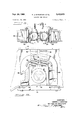
- FIG. 15 is a fragmentary front elevational view of a journal box arrangement and showing another embodiment for resiliently supporting the truck side frames thereon;
- FIG. 16 is a fragmentary front elevational view of a journal box arrangement and showing still a further embodiment for supporting the truck side frames thereon.
- the truck comprises generally a wheel axle unit 10, or trucks, including wheel axles 11, wheels 12, and journal boxes 13 mounted in side frame units 14.
- the truck 10 is shown directly attached to the underside of a transit vehicle body 16 including an underframe 17 as more fully to be explained hereinafter.
- the side frame units 14 include side frame members 18-18 from each of which there extends a stem or transom 19.
- the transoms 19-19 are each offset toward one end of the respective side frame members 18-18 so as to be lengthwise spaced from each other to provide a space 21 therebetween.
- the side frame members 18-18 are generally fabricated to form a hollow section defined by two transversely spaced side webs 22-22, and top and bottom plates 23 and 24 fixed on the upper and lower edges respectively of the side webs 22.
- the transoms 19 may similarly be formed with hollow sections adjacent the ends fixed to the side frame members 18-18 and with I-beam sections as shown for example in FIG. 5, including an upright wall 25, top and bottom plates 26 and 27. Adjacent the free ends as shown in FIG. 7 there is disposed and fastened between the top and bottom plates 26 and 27 a rectangular block 28.
- the side frames 18-18 are each formed with an intermediate section providing a substantially horizontal platform 29 which is disposed between a pair of longitudinally spaced wheel supporting sections 30.
- the wheel supporting sections or pedestal legs 30 of the frames 18-18 are of the pedestal type and are each formed with inverted U-shaped cut-outs or pedestal jaws for accommodating the journal box assembly 13.
- the journal-box assembly 13 comprises a journal box housing 53 incorporating the conventional journal elements not shown.
- the journal box housing 53 is formed along its sides with outwardly extending flanges 54 which are guided within guide means 55-55 suitably fixed to the side defining the inverted U-shaped opening 52.
- the journal box housing is suitably fixed to the respective 3 ends of the axle assembly 11 inboard of the frames 1818 and the wheels 12 fixed outboard thereof.
- springs 56-56 are seated at one end in guide cups 5757 formed on the upper side of the journal housing 53. At the other ends the Springs 5656 are seated within guides 5858 fixed to the underside of the top web plate 23.
- FIG. A further modification for resiliently supporting the side frames 18-18 on the axles 11 is illustrated in FIG. wherein there is employed a resilient pad 200.
- the resilient pad such as a rubber pad, 200 is disposed and adhered between a pair of plates 201 and 202.
- Fixed to the upper plate 201 are a pair of longitudinally spaced bosses 203 which are seatable within the guides 58-58.
- Similar bosses 204 are fixed to the lower plate and seated within the journal box guide cups 5757.
- the bosses 203 and 204 are each preferably formed from hollow cylindrical tubing of which the free ends are covered by a disc 206.
- FIG. 16 there is provided a cylindrical support 300 fixed at one end to the upper surface of a plate 301 from the underside of which there depend hollow cylindrical bosses 302 which are nested at the free ends thereof in the journal box guide cups 5757. At its upper end the cylindrical support 300 is formed with a spherical concave surface 303.
- Seated on the concave surface 303 is a substantially complementary spherical con'vex surface 304 formed on one end of a column 306.
- the column 306 is fixed to the underside of plate 307 from the upper side of which there depends a pair of bosses 308 received within the guides 58-58.
- the bosses 308 which may be formed from hollow cylinders may be closed by discs 309. The foregoing structure permits relative rocking movement of the side frame units 1414 and the axles 11 by way of the contacting spherical convex surface 304 on the column 306 with the spherical concave surface 303.
- tread brake units 59 Mounted on the exterior of the frames 1818 and coacting with the wheels may be self-contained tread brake units 59.
- the tread brake units 59 may be of conventional design and further description thereof is not deemed necessary inasmuch as the units do not form an essential part of the invention.
- each of the transoms 19 is integrally fixed to a respective one of the side frames 18 and the free end extends toward an opposing one of the frames 18.
- a shaft 31 which is fixed at one end as by a bolt within an opening 35 of the block 28.
- the shaft 31 is formed with a section 33 of reduced diameter on which there is seated a sperical bearing 34.
- Fixing the spherical bearing 34 against longitudinal movement on the section 33 is a nut 36 which is threaded on a thread end 37 of the shaft 31.
- the nut 36 'bears against a collar 38 which encompasses the thread end 37 and bears against the spherical bearing 34 as shown in FIG. 10. Securing the nut against turning on the thread end 37 is a cotter or dowel pin 38a.
- the spherical bearing 34 is seated within a bushing 39 which is supported in a bushing sleeve 41 inserted in a bearing housing 42 seated within the side walls 22 of the side frame 18.
- the housing 42 is suitably fixed within aligned openings in the side walls 22 by means of welding or the like.
- an insert sleeve or collar 45 having a flange 46 which abuts against the outer terminal end of the bush- 4.
- ing sleeve 41 Fixed to the collar is a dust cover 48 formed with a sleeve 49 which embraces the shaft 31 and is loosely clamped by a sleeve clamp 51.
- the dust cover 48 may be fixed to the collar 45 by means of screws 52 which extend through the flange 46 of the collar into the bearing housing 42 and therefore also retain the sleeve 41 fixed to the collar 45.
- transoms 1919 With the transoms 1919 connected as described above there is provided a pivot axis A extending diagonally between the lengthwise spaced connections.
- the side frames are pivotal relative to each other about the diagonal pivot axis whereby the four wheels of the truck are capable of traversing roadbeds having the tracks at different heights and different angles. This imparts a smooth ride to the car body on which the truck is mounted.
- the transoms 1919 maintain a constant and uniform lateral spacing between the side frames 19 so as to impart a stability and rigidity to the truck.
- the truck 10, constructed as heretofore generally described, is directly attached to the underframe 17 of the transit car 16.
- the hanger 60 which may be formed as by a casting comprises a top plate 61 from which there depend two longitudinally spaced webs 62, two depending transversely spaced webs 63, and a bottom plate 64.
- Bolted to the bottom plate is a first hanger bracket 66 and a second lengthwise spaced hanger bracket 67.
- the hanger 60 and brackets 66 and 67 are located to depend within the space 21 defined by the lengthwise spaced transoms 19-19.
- the foregoing described hanger 60 is connected and fixed to the underside of the car body 16 by means of bolts 68 which are fastened to a transversely extending plate 69 extending across the bottom or underside of the underframe 17.
- the plate 69 may be spaced from. the underframe members by means of vertically downwardly depending webs 71 fixed to a plate extending between the side sills of the transit car.
- resilient connecting members 72 and 73 Connecting the hanger 60 to the side frame units 1414 so as to permit relative movement of the truck 10 and car body 17 in vertical and lateral directions and relative pivotal or swivelling movement are resilient connecting members 72 and 73.
- the resilient connecting member 72 is supported by the hanger 66 and the transom 19 of one of the side frames 18 and the other resilient member 73 is connected between the bracket 67 and the transom 19 of the other remaining side frame member 18.
- the resilient connecting member 72 includes a shaft or rod 74 having mounted on one end thereof a pair of annular resilient pads 76 and 76a formed from rubber or the like and shaped in the form of a disc and having an annular flange 77 which projects into a circular opening 78 provided in a web of the hanger bracket 66.
- Compressing the outer face of the resilient pad 76 against the opposing face of the web 75 is an annular plate 79 which is held fixed by means of a nut 81 threaded on the end of the rod 74.
- the pad 76a is held compressed by means of a spacer assembly 82 including an annular plate which compresses the annular pad 76a against the web 75.
- Fixed to the plate 80 is one end of a cylinder 84 which is coaxially disposed about the shaft 74 and has fixed to its other end a similar annular plate 80a.
- the plate 80a compresses a resilient pad 85a which is of a similar construction to the pad 76a and includes an annular flange which is diposed within an opening 86 formed in the transom web plate 25. Disposed on the opposite side of the web plate 25 is a second annular resilient pad 85 also formed with an annular flange 90. The pad 85 is held compressed between the web plate 25 and a second annular plate 79 which is held in position by means of the nut 81a threaded on the end of shaft 74.
- the resilient connection 73 is similar to the construction of the resilient connection 72 including a shaft 88 having mounted on one end a pair of the annular resilient pads 89 and 89a and on the other end a pair of pads 97 and 97a.
- the pads 89 and 89a and pads 97 and 97a are each formed with annular lips 90 and 98, respectively.
- Disposed between the pads 89a and 97a is a clamping assembly 105 including a coaxial sleeve 94 disposed about the shaft 88.
- annular resilient pads 89 and 89a are disposed with the annular flanges seated within an opening 95 formed in the vertical web 25 fixed between the upper and lower plates 26 and 27 of the other of the transoms 19. Holding the annular resilient pad 89 compressed against the web 25 is an annular clamping plate 91 which is held in clamping position by means of a nut 93 threaded on the end of the shaft 88.
- annular resilient pads 97 and 97d are located on opposite sides of a web 99 of the bracket 67 With the annular lips 98 of each pad disposed within an opening 103 formed in the web 99. Holding the pad 97 compressed against the web 99 is an annular clamping plate 101 which is held in clamping position by means of a nut 102 threaded on the end of the shaft 88. The other resilient pad 97a is held compressed by means of a plate 96 fixed to the end of the sleeve 94 of the clamping assembly 105. The other end of the sleeve 94 has fixed thereto a second clamping plate 92 which compresses the resilient pad 89a against the transom web 25.
- shims 83 may be inserted between the plates and respective pads. Similar shims 83 may be used for the same purpose in the resilient connection 72.
- the resilient connections 72 and 73 are axially spaced and vertically aligned from each other and also in overlying parallel relationship. This arrangement utilizes a minimum amount of space while effectively connecting the truck to the vehicle body 16. Moreover, the resilient connections 72 and 73 permit the relative rocking movement of the side frame units 14 in a vertical plane relative to each other about the spaced transom connections heretofore described. This is achieved by the yielding of the resilient pads 76-7611, 85-8511, 89-89a and 97-9711 supporting the shafts 74 and 88, respectively, so that the latter are substantially independently responsive to the vertical movement of side frame units 14--14.
- the above described resilient connections 72 and 73 permit the relative turning of the trucks 10 and the vehicle body 16.
- the spaced trucks 10 mounted on the underside of the body 16, swivel in a horizontal plane relative to the vehicle body.
- the side frames 18-18 and the transoms 19-19 fixed thereto are turned in the direction of curvature of the tracks so that ends of the shafts 74 and 88 mounted on the transoms 1919 are turned in a horizontal plane.
- the other ends of the shafts 74 and 88 are held in the hanger brackets 66 and 67 fixed to the vehicle body 16 by way of the hanger 60.
- the pads 85-8511 and 76-76a, and pads 89-89a and 97-97a are further compressed into a wedge shape resisting the direction of turning of the vehicle body 16 relative to the truck frames.
- the compression on the pads 858 5a and 76-76a and pads 89-89a and 97-9711 is controlled so as to permit a maximum relative turning of about 5 between the vehicle body 16 and the trucks 10.
- Such control of the compression may be obtained by the adjustment of the nuts 81, 81a, 93 and 102, and the insertion or deletion of shims 83.
- the resisting force of the compressed resilient pads is also used to assist in the vertical realignment of the vehicle body 16 with the trucks 10 as more fully to be explained hereinafter.
- each of the transoms 19 Fixed to the top web 26 of each of the transoms 19 is a safety lug which is arranged to be disposed over the bottom plate 64 of the hanger 60.
- the safety lugs 100 serve to prevent complete separation of the truck 10 from the car body 16 in the event of an accident.
- the vehicle springs 110 are of the helical type of which one end of each is supported in a cup housing 112 (FIG. 12) fixed as by welding to the respective top plates 23 of the side frame members 18 and the other end is received within a cup shaped housing 113 which is fixed as by bolts to the plate 69 mounted on the underside of the vehicle body 16.
- the helical springs 110--110 are of such strength as to support resiliently the unloaded weight of the vehicle body 16 and to withstand the lateral horizontal deflection due to relative displacement and pivoting of the vehicle body and truck frames.
- the air springs 111 serve to maintain the vehicle body spacing or level constant under the load of the passengers carried by the vehicle.
- the air spring 111 may be of substantially conventional structure including an expandable fluid chamber formed by a flexible housing 116 to one end of which there is fixed a base 117 having a shear boss 118 which is received within a complementary opening 119 formed in the top plate 23 of the side frame 18.
- Fixed to the upper end of the flexible housing 116 is a cover 121 having a boss 122 which is received within an opening 123 formed in the truck mounting plate 69. Fixing the cover 121 and thereby the air spring 111 to the plate 69 is a plurality of bolts. As shown in FIGS.
- the chamber 114 is connected to a suitable regulated fluid source including the usual level control valve assembly 127 which serves to sense the weight of the load being carried by way of the vertical deflection of the vehicle body relative to the truck 10 and to regulate the the fluid air pressure within the chamber 114 and thereby maintain the desired level of the body above the trucks.
- the level control assembly is of generally conventional structure so that a further description is not deemed necessary.
- each of the side frames 1818 and the underside of the vehicle body 16 may be telescoping shock absorbers 129 as shown in FIGS. 2 and 4.
- One end of each of the shock absorbers 129 is mounted for vertical movement with the side frame 18 between cushion pads 128 permitting limited rocking movement of the end on the side frame.
- the other end is connected to the plate 69 for movement therewith similarly between cushion pads 128.
- the shock absorbers 129 connected in this manner are operative to absorb or cushion vertical shocks while being substantially universally movable at least to the degree necessary at each end to accommodate the relative horizontal movement between the vehicle body 16 and the truck 10.
- the swiveling movement occurs during the traversal of the vehicle on curved trackage so that the longitudinal axis of the vehicle body 16 and the directionof movement of the trucks are not aligned.
- the truck springs which are fixed between the underframe 17 and the truck side frames are laterally deflected so as to provide a torsional force resisting such relative turning.
- the annular pads 76-76a, 85-85a, 8989a and 97-97a are also angularly compressed to provide an additional force resisting the turning movement.
- a railway vehicle including a body and a truck, said truck comprising:
- said side frames each having longitudinally spaced journal box receiving means to accommodate journal box assemblies the-rein for relative vertical movement
- journal box assemblies being mounted on the axles of said wheel and axle assemblies and received by said journal box receiving means,
- resilient means supporting said side frames on said journal box assemblies so that said side frames and said wheel and axle assemblies are relatively vertically movable
- a rail vehicle truck for supporting a vehicle body
- said truck comprising:
- each unit including a longitudinally extending side frame and a transom extending transversely therefrom toward the opposite side frame,
- transoms being relatively longitudinally spaced apart
- connecting means connecting the ends of said transoms to the respectively opposite side frame to permit pivotal movement of said unit about a diagonal pivot axis extending through said connecting means
- each said side frame having pedestal type end portions including pedestal legs defining inverted U-shaped pedestal jaws
- journal box assembly vertically slidably supported in each pedestal jaw
- said vertical spring means resiliently resisting turning movement of said body relative to said truck and retaining means disposed on said frame units and extending into interengaging relationship with said vehicle body to define a limit of vertical movement between the truck and said body.
- a rail vehicle truck for supporting a vehicle body
- said truck comprising:
- a frame including two opposed side frame units of substantially T-shape
- each unit including a longitudinally extending side frame and a transom extending transversely therefrom toward the opposite side frame unit,
- transoms each being longitudinally displaced to provide a space therebetween
- connecting means connecting the ends of said transoms to the respective opposite side frame unit to permit pivotal movement of said side frame units about a diagonal pivot axis extending through said connecting means
- said attaching means including hanger means fixedly mounted on the vehicle body and projecting downwardly into said space,
- said resilient means includes first and second members each having an end portion resiliently connected to said hanger means,
- first and second members extending longitudinally in opposite directions away from said hanger means toward an adjacent one of said transoms, and resilient means connecting each of said first and second members to said respective adjacent transom.
- journal box assembly vertically slidably supported in each cut out
- said spring means includes helical springs mounted on said side frame units, and
- a rail vehicle truck for supporting a vehicle body, said truck comprising:
- each unit including a longitudinally extending side frame and a transom extending transversely therefrom toward the opposite side frame,
- transoms being longitudinally spaced apart
- connecting means connecting the ends of said transoms to the respectively opposite side frame to permit pivotal movement of said side frame units about a diagonal pivot axis extending through said connect ing means
- said attaching means including springs supporting said vehicle body on said side frame units and permitting limited pivotal movement of said side frame units about said diagonal pivot axis,
- a railway vehicle truck for connection directly to a transit vehicle body, said truck comprising a frame ine uding t-wo opposed rigid side frame units of substantially T-shape, each unit including a rigidly extending side frame and a transom extending transversely therefrom toward the opposite side frame unit, said transoms each being offset to provide a longitudinal extending space therebetween, connecting means connecting the ends of said transoms to the respective opposite side frame unit to permit relative pivoting of said side frame units about a diagonal axis extending between said connecting means, attaching means for attaching said truck directly to the frame of the transit vehicle body, said attaching means including hanger means fixedly mounted on the vehicle body against turning and projecting downwardly between said side frame units and into said longitudinal space between said offset transoms, first resilient means extending between said hanger means and one of said transoms, and second resilient means extending between said hanger and the other of said transoms, said first and second resilient means being disposed in vertically spaced alignment on the longitudinal center line
- a railway vehicle truck for connection directly to a transit vehicle body, said truck comprising a frame including two opposed rigid side frame units of substantially T-shape, each unit including a longitudinally extending side frame and a transom extending transversely therefrom toward the opposite side frame unit, said transoms each being offset to provide a longitudinally extending space there'between, means connecting the ends of said transoms to the respective opposite side frame unit to permit relative pivoting of said side frame units in a vertical plane relatively to each other about a diagonal axis extending between said connecting means, attaching means for attaching said truck directly to the underside of the transit car body, said attaching means including hanger means fixedly mounted on the car body against turning and projecting downwardly between said side frame units and into said longitudinal space between said offset transom, first shaft means extending between said hanger means and one of said transoms, second shaft means extending between said hanger and the other of said transoms, said first and second shaft means being disposed in vertically spaced alignment on the longitudinal center line
- a railway vehicle truck for connection directly to a transit vehicle body, said truck comprising a wheeled axle assembly, a frame including two opposed rigid side frame units of substantially T-shape supported on said wheeled axle assembly, each unit including a rigidly extending side frame and a transom extending transversely therefrom toward the opposite side frame unit, said transoms each being olfset to provide a longitudinal extending space therebetween, means connecting the ends of said transoms to the respective opposite side frame unit to permit turning of said side frame units in a vertical plane relatively to each other, attaching means for attaching said truck directly to the frame of the transit vehicle body, said attaching means including hanger means fixedly mounted on the vehicle body against turning and projecting downwardly betwen said side frame and into said longitudinal space between said oifset transoms, first resilient means extending between said hanger means and one of said transoms, and second resilient means extending between said hanger and the other of said transoms, said first and second resilient means being disposed in vertical
- said means disposed between said journal box means and said side frame units includes a resilient pad disposed between a pair of metal plates, said metal plates having means projecting from the respective outer face and engaging the underside of the side frame units and top sides of the journal box assemblies.
- said means disposed betwen said journal box means and said side frame units includes a concave support mounted on the upper face of said journal box and a post having a substantially complementary convex face seated within said concave support and extending upwardly to engage at the upper end thereof the underside of said side frame unit.
- a railway vehicle truck for connection directly to a transit vehicle body, said truck comprising a frame including two opposed rigid side frame units of substantially T-shape, each unit including a rigidly extending side frame and a transom extending transversely therefrom toward the opposite side frame unit, said transoms each being offset to provide a longitudinal extending space therebetween, means connecting the ends of said transoms to the respective opposite side frame unit to permit turning of said side frame units in a vertical plane relatively to each other, attaching means for attaching said truck directly to the frame of the transit vehicle body, said attaching means including hanger means fixedly mounted on the vehicle body against turning and projecting downwardly between said side frame units and into said longitudinal space between said offset transoms, first resilient means extending between said hanger means and one of said transoms, second resilient means extending between said hanger and the other of said transoms, said first and second resilient means being disposed in vertically spaced alignment on the longitudinal center line of the truck to permit limited flexing and turning of said truck side frame units
Landscapes
- Engineering & Computer Science (AREA)
- Mechanical Engineering (AREA)
- Body Structure For Vehicles (AREA)
Description
P 1968 A. J. CHRISTIAN ETAL 3,402,679
RAILWAY CAR TRUCKS Filed Oct. 23, 1965 ll Sheets-Sheet 1 I c Q m m v v a E an a [D 2 g l j or o a I E a l j (\l l INVENTORS ANDREW J. CHRISTIAN P 1968 A. J. CHRISTIAN ETAL 3,402,679
RAILWAY CAR TRUCKS Filed Oct. 23, 1965 ,ll Sheets-Sheet 2 INVENTORS ANDREW J. CHRIST/AN WILL/AM VAN DE SLUYS %//?;,4
RAILWAY CAR TRUCKS Filed Oct. 23, 1965 ll Sheets-Sheet 5 I i w R INVENTORS ANDREW .1. CHRISTIAN WILLIAM VAN ER LUYS W 7 P 1968 A. J. CHRISTIAN ETAL 3,402,679
RAILWAY CAR TRUCKS Filed Oct. 25, 1965 11 Sheets$heet 5 IN VE N TORS ANDREW J. CHRISTIAN WIL IAM VAN 0 R SLUYS BY ATT Y Sept. 1968 A. J. CHRISTIAN ETAL 3,402,679
RAILWAY CAR TRUCKS Filed Oct. 23, 1965 11 SheetsSheet 6 IN VE N TORS ANDREW J. CHRIS TIAN WILL! M VAN DE SLUYS BYW ATT'Y P 4, 1968 A. J. CHRISTIAN ETAL 3,402,679
RAILWAY CAR TRUCKS Filed Oct. 23, 1965 ll Sheets-Sheet 7 INVENTORS ANDREW J. CHRISTIAN [\I WILLIAM VAN ER SLUYS wfiggaz u ATT'Y l 1968 A. J. CHRISTIAN ETAL 3,402,679
RAILWAY CAR TRUCKS Filed Oct. 23, 1965 ll Sheets-Sheet 8 7 a "i 7A 9 M I Q I ii A Q /F- 3 N l i g? ggi l A;
1 1% w s In ('9 i r 2 l Z INVENTORS ANDREW J. CHRISTIAN WILL/A VAN ER LUYS W Sept. 24, 1963 A. J. CHRISTIAN ETAL 3,402,679
RAILWAY CAR TRUCKS Filed Oct. 23,. 1965 11 Sheets-Sheet 9 ANDREW J. CHRISTIAN WILLIAM VANER LUYS BYg-ZZ ATT'Y p 1968 A. J. CHRISTIAN ETAL 3,402,679
RAILWAY CAR TRUCKS Filed Oct. 23, 1965 ll Sheets-Sheet 10 INVENTORS' ANDREW J- CHRIS TIAN WILLIAM VAN DER LUYS 1 BY W ATT'Y P 1968 A. J. CHRISTIAN ETAL 3,402,679
RAILWAY CAR TRUCKS Filed Oct. 23, 1965 11 Sheets-Sheet 11 206 20 m. I I "'H h m 58 1 1 l l u 58 I I H I1 I 'I 1 H J i 1 2o: 22 "1 n" "1 'Hl; 2"" 202 I it "I 204 1 204 sv 51 54 309 309 I H W. 'W/ ""n. A
ll 5 2. I :lj: I 58 ll i II: I 3 2? 30s I a 303 300 301 3O l| l I 57 1 1572 54 I i/I l 54 1 l I N "I I I I IN VE N TORS ANDREW J CHRISTIAN WILLIAM VAN DER SLUYS United States Patent 3,402,679 RAILWAY CAR TRUCKS Andrew 1. Christian, Chicago, and William Van Der Sluys, Homewood, Ill., assignors to Pullman Incorporated, Chicago, III., a corporation of Delaware Filed Oct. 23, 1965, Ser. No. 502,840 14 Claims. (Cl. 105-199) ABSTRACT OF THE DISCLOSURE A railway vehicle truck for direct connection to a transit vehicle body including a pair of oppositely disposed side frames, each frame having a transversely extending transom and connecting means pivotally connecting the free end of each transom to the opposite frame with the transoms being longitudinally spaced from each other so that the frames are pivotal relative to each other about a diagonal axis extending through the connecting means; the side frames are supported by a pair of longitudinally spaced and transversely extending wheel and axle assemblies which are attached to the side frames by journal box assemblies having resilient means whereby the wheel and axle assemblies have relatively greater movement vertically than longitudinally.
The present invention relates to railway vehicle trucks and in particular to .a lightweight railway vehicle truck for use with transit railway vehicles.
It is the principal object of the present invention to provide a lightweight truck for transit railway vehicles.
It is another object to provide a railway vehicle truck for transit railway vehicles which is constructed in a manner so that the bolster, centerplate, and truck bolsters conventionally used to mount the truck on the vehicle body are eliminated and thereby reduce the overall weight of the truck and transit vehicle.
It is still a further object to provide a railway vehicle truck with a new and novel arrangement for resiliently connecting the truck directly to the vehicle body so that the truck and vehicle body are permitted limited relative movement in a vertical and horizontal plane.
It is still a further object to provide a railway vehicle truck with a new and novel arrangement for resiliently connecting the truck to the vehicle body, and connecting the truck springs directly to the vehicle body so that the truck springs are laterally and longitudinally deflectable during relative movement of the vehicle body and truck.
Further objects and features will hereinafter appear.
In the drawings:
FIG. 1 is a fragmentary side elevational view of a transit vehicle body mounted on a railway vehicle truck embodying the principles of the present invention;
FIG. 2 is .an enlarged side elevational view showing the railway vehicle truck of the present invention mounted on the underside of a transit vehicle body;
FIG. 3 is a top plan view of the railway vehicle truck;
FIG. 4 is a perspective view of the railway vehicle truck and showing in phantom the connecting plates on the underside of the railway transit vehicle;
FIG. 5 is across-sectional view taken generally along the lines of 5-5 of FIG. 3 and showing the arrangement for connecting the railway vehicle truck directly to the underside of the transit vehicle body;
FIG. 6 is .a perspective view of the railway vehicle truck similar to FIG. 5;
FIG. 7 is a view taken generally along the lines 77 of FIG. 3 and showing in particular one of the side frame stems extending between and connecting the two laterally spaced side frames of the track;
Patented Sept. 24, 1968 FIG. 8 is a top plan view of the hanger means used to connect the truck directly to the underside of the vehicle body;
FIG. 9 is a cross sectional view taken generally along the lines of 9-9 of FIG. 5 and showing in particular an end elevational view of the hanger;
FIG. 10 is a cross sectional view taken through the connection of the stem of one of the side frames to the opposite one of the side frames;
FIG. 11 is a view taken generally along the lines 11-11 of FIG. 7 and showing in particular the connection of the leveling valve between the transit vehicle body and the truck;
FIG. 12 is a view taken generally along lines 12-12 of FIG. 3 and showing in particular the connection of the vehicle body springs and the air spring to the truck frame and the underside of the railway car;
FIG. 13 is a fragmentary top plan view of the journal box arrangement seated within the side frame;
FIG. 14 is a fragmentary front elevational view of the journal box arrangement illustrated in FIG. 13;
FIG. 15 is a fragmentary front elevational view of a journal box arrangement and showing another embodiment for resiliently supporting the truck side frames thereon; and
FIG. 16 is a fragmentary front elevational view of a journal box arrangement and showing still a further embodiment for supporting the truck side frames thereon.
Referring now to the drawings, in particular, FIGS. 1-4, embodying the principles of the present invention, the truck comprises generally a wheel axle unit 10, or trucks, including wheel axles 11, wheels 12, and journal boxes 13 mounted in side frame units 14. The truck 10 is shown directly attached to the underside of a transit vehicle body 16 including an underframe 17 as more fully to be explained hereinafter.
The side frame units 14 include side frame members 18-18 from each of which there extends a stem or transom 19. The transoms 19-19 are each offset toward one end of the respective side frame members 18-18 so as to be lengthwise spaced from each other to provide a space 21 therebetween.
The side frame members 18-18, as shown for example in FIG. 10, are generally fabricated to form a hollow section defined by two transversely spaced side webs 22-22, and top and bottom plates 23 and 24 fixed on the upper and lower edges respectively of the side webs 22. The transoms 19 may similarly be formed with hollow sections adjacent the ends fixed to the side frame members 18-18 and with I-beam sections as shown for example in FIG. 5, including an upright wall 25, top and bottom plates 26 and 27. Adjacent the free ends as shown in FIG. 7 there is disposed and fastened between the top and bottom plates 26 and 27 a rectangular block 28.
As shown in FIG. 4, the side frames 18-18 are each formed with an intermediate section providing a substantially horizontal platform 29 which is disposed between a pair of longitudinally spaced wheel supporting sections 30.
As shown in particular in FIGS. 13 and 14, the wheel supporting sections or pedestal legs 30 of the frames 18-18 are of the pedestal type and are each formed with inverted U-shaped cut-outs or pedestal jaws for accommodating the journal box assembly 13. Generally, the journal-box assembly 13 comprises a journal box housing 53 incorporating the conventional journal elements not shown. The journal box housing 53 is formed along its sides with outwardly extending flanges 54 which are guided within guide means 55-55 suitably fixed to the side defining the inverted U-shaped opening 52. The journal box housing is suitably fixed to the respective 3 ends of the axle assembly 11 inboard of the frames 1818 and the wheels 12 fixed outboard thereof.
For resiliently resisting the vertical movement of the wheel and axles relative to the frames 1818 springs 56-56 are seated at one end in guide cups 5757 formed on the upper side of the journal housing 53. At the other ends the Springs 5656 are seated within guides 5858 fixed to the underside of the top web plate 23.
A further modification for resiliently supporting the side frames 18-18 on the axles 11 is illustrated in FIG. wherein there is employed a resilient pad 200. The resilient pad, such as a rubber pad, 200 is disposed and adhered between a pair of plates 201 and 202. Fixed to the upper plate 201 are a pair of longitudinally spaced bosses 203 which are seatable within the guides 58-58. Similar bosses 204 are fixed to the lower plate and seated within the journal box guide cups 5757. In order to maintain the weight at a minimum the bosses 203 and 204 are each preferably formed from hollow cylindrical tubing of which the free ends are covered by a disc 206.
It is to be noted that the springs 56-56 and the resilient pad 200 of the embodiments illustrated in FIGS. 14 and 15 permit relative rocking movement of the side frame units 14 and the axles 11 while resiliently resisting the relative vertical movement. In the event that the vertical resilient support between the axle 11 and side frame units 1414 is not desired, the embodiment of FIG. 16 may be used. As shown, there is provided a cylindrical support 300 fixed at one end to the upper surface of a plate 301 from the underside of which there depend hollow cylindrical bosses 302 which are nested at the free ends thereof in the journal box guide cups 5757. At its upper end the cylindrical support 300 is formed with a spherical concave surface 303.
Seated on the concave surface 303 is a substantially complementary spherical con'vex surface 304 formed on one end of a column 306. At its other end the column 306 is fixed to the underside of plate 307 from the upper side of which there depends a pair of bosses 308 received within the guides 58-58. The bosses 308 which may be formed from hollow cylinders may be closed by discs 309. The foregoing structure permits relative rocking movement of the side frame units 1414 and the axles 11 by way of the contacting spherical convex surface 304 on the column 306 with the spherical concave surface 303.
Mounted on the exterior of the frames 1818 and coacting with the wheels may be self-contained tread brake units 59. The tread brake units 59 may be of conventional design and further description thereof is not deemed necessary inasmuch as the units do not form an essential part of the invention.
As shown in FIGS. 7 and 10, one end of each of the transoms 19 is integrally fixed to a respective one of the side frames 18 and the free end extends toward an opposing one of the frames 18. Connecting each of the free ends of the transoms 19 to the opposing one of the frames 18 is a shaft 31 which is fixed at one end as by a bolt within an opening 35 of the block 28. At its other end, the shaft 31 is formed with a section 33 of reduced diameter on which there is seated a sperical bearing 34. Fixing the spherical bearing 34 against longitudinal movement on the section 33 is a nut 36 which is threaded on a thread end 37 of the shaft 31. The nut 36 'bears against a collar 38 which encompasses the thread end 37 and bears against the spherical bearing 34 as shown in FIG. 10. Securing the nut against turning on the thread end 37 is a cotter or dowel pin 38a.
The spherical bearing 34 is seated within a bushing 39 which is supported in a bushing sleeve 41 inserted in a bearing housing 42 seated within the side walls 22 of the side frame 18. The housing 42 is suitably fixed within aligned openings in the side walls 22 by means of welding or the like. Further holding the bushing 39 against displacement is an insert sleeve or collar 45 having a flange 46 which abuts against the outer terminal end of the bush- 4. ing sleeve 41. Fixed to the collar is a dust cover 48 formed with a sleeve 49 which embraces the shaft 31 and is loosely clamped by a sleeve clamp 51. The dust cover 48 may be fixed to the collar 45 by means of screws 52 which extend through the flange 46 of the collar into the bearing housing 42 and therefore also retain the sleeve 41 fixed to the collar 45.
With the transoms 1919 connected as described above there is provided a pivot axis A extending diagonally between the lengthwise spaced connections. Thus the side frames are pivotal relative to each other about the diagonal pivot axis whereby the four wheels of the truck are capable of traversing roadbeds having the tracks at different heights and different angles. This imparts a smooth ride to the car body on which the truck is mounted. At the same time it is to be noted that the transoms 1919 maintain a constant and uniform lateral spacing between the side frames 19 so as to impart a stability and rigidity to the truck.
In accordance with the present invention the truck 10, constructed as heretofore generally described, is directly attached to the underframe 17 of the transit car 16. To this end there is provided the hanger as shown particularly in FIGS. 3, 4 and S. The hanger 60 which may be formed as by a casting comprises a top plate 61 from which there depend two longitudinally spaced webs 62, two depending transversely spaced webs 63, and a bottom plate 64. Bolted to the bottom plate is a first hanger bracket 66 and a second lengthwise spaced hanger bracket 67. The hanger 60 and brackets 66 and 67 are located to depend within the space 21 defined by the lengthwise spaced transoms 19-19.
The foregoing described hanger 60 is connected and fixed to the underside of the car body 16 by means of bolts 68 which are fastened to a transversely extending plate 69 extending across the bottom or underside of the underframe 17. To achieve the desired clearance between the underside of the body and the rail track level the plate 69 may be spaced from. the underframe members by means of vertically downwardly depending webs 71 fixed to a plate extending between the side sills of the transit car.
Connecting the hanger 60 to the side frame units 1414 so as to permit relative movement of the truck 10 and car body 17 in vertical and lateral directions and relative pivotal or swivelling movement are resilient connecting members 72 and 73. In the form shown the resilient connecting member 72 is supported by the hanger 66 and the transom 19 of one of the side frames 18 and the other resilient member 73 is connected between the bracket 67 and the transom 19 of the other remaining side frame member 18.
As shown in particular in FIGS. 5 and 6, the resilient connecting member 72 includes a shaft or rod 74 having mounted on one end thereof a pair of annular resilient pads 76 and 76a formed from rubber or the like and shaped in the form of a disc and having an annular flange 77 which projects into a circular opening 78 provided in a web of the hanger bracket 66. Compressing the outer face of the resilient pad 76 against the opposing face of the web 75 is an annular plate 79 which is held fixed by means of a nut 81 threaded on the end of the rod 74. The pad 76a is held compressed by means of a spacer assembly 82 including an annular plate which compresses the annular pad 76a against the web 75. Fixed to the plate 80 is one end of a cylinder 84 which is coaxially disposed about the shaft 74 and has fixed to its other end a similar annular plate 80a.
The plate 80a compresses a resilient pad 85a which is of a similar construction to the pad 76a and includes an annular flange which is diposed within an opening 86 formed in the transom web plate 25. Disposed on the opposite side of the web plate 25 is a second annular resilient pad 85 also formed with an annular flange 90. The pad 85 is held compressed between the web plate 25 and a second annular plate 79 which is held in position by means of the nut 81a threaded on the end of shaft 74.
The resilient connection 73 is similar to the construction of the resilient connection 72 including a shaft 88 having mounted on one end a pair of the annular resilient pads 89 and 89a and on the other end a pair of pads 97 and 97a. The pads 89 and 89a and pads 97 and 97a are each formed with annular lips 90 and 98, respectively. Disposed between the pads 89a and 97a is a clamping assembly 105 including a coaxial sleeve 94 disposed about the shaft 88.
The annular resilient pads 89 and 89a are disposed with the annular flanges seated within an opening 95 formed in the vertical web 25 fixed between the upper and lower plates 26 and 27 of the other of the transoms 19. Holding the annular resilient pad 89 compressed against the web 25 is an annular clamping plate 91 which is held in clamping position by means of a nut 93 threaded on the end of the shaft 88.
At the other end of the shaft 88 the annular resilient pads 97 and 97d are located on opposite sides of a web 99 of the bracket 67 With the annular lips 98 of each pad disposed within an opening 103 formed in the web 99. Holding the pad 97 compressed against the web 99 is an annular clamping plate 101 which is held in clamping position by means of a nut 102 threaded on the end of the shaft 88. The other resilient pad 97a is held compressed by means of a plate 96 fixed to the end of the sleeve 94 of the clamping assembly 105. The other end of the sleeve 94 has fixed thereto a second clamping plate 92 which compresses the resilient pad 89a against the transom web 25. To achieve the desired clamping pressure of the plates 92 and 96 of the clamping assembly 105 on the respective resilient pads 89a and 97a shims 83 may be inserted between the plates and respective pads. Similar shims 83 may be used for the same purpose in the resilient connection 72.
It is to be noted that the resilient connections 72 and 73 are axially spaced and vertically aligned from each other and also in overlying parallel relationship. This arrangement utilizes a minimum amount of space while effectively connecting the truck to the vehicle body 16. Moreover, the resilient connections 72 and 73 permit the relative rocking movement of the side frame units 14 in a vertical plane relative to each other about the spaced transom connections heretofore described. This is achieved by the yielding of the resilient pads 76-7611, 85-8511, 89-89a and 97-9711 supporting the shafts 74 and 88, respectively, so that the latter are substantially independently responsive to the vertical movement of side frame units 14--14.
During train operation when the transit vehicle is traversing a curve the above described resilient connections 72 and 73 permit the relative turning of the trucks 10 and the vehicle body 16. As the vehicle traverses the curves the spaced trucks 10, mounted on the underside of the body 16, swivel in a horizontal plane relative to the vehicle body. Upon such swiveling the side frames 18-18 and the transoms 19-19 fixed thereto are turned in the direction of curvature of the tracks so that ends of the shafts 74 and 88 mounted on the transoms 1919 are turned in a horizontal plane. The other ends of the shafts 74 and 88 are held in the hanger brackets 66 and 67 fixed to the vehicle body 16 by way of the hanger 60.
During the turning movement of the shafts 74 and 88, the pads 85-8511 and 76-76a, and pads 89-89a and 97-97a are further compressed into a wedge shape resisting the direction of turning of the vehicle body 16 relative to the truck frames. Preferably the compression on the pads 858 5a and 76-76a and pads 89-89a and 97-9711 is controlled so as to permit a maximum relative turning of about 5 between the vehicle body 16 and the trucks 10. Such control of the compression may be obtained by the adjustment of the nuts 81, 81a, 93 and 102, and the insertion or deletion of shims 83. The resisting force of the compressed resilient pads is also used to assist in the vertical realignment of the vehicle body 16 with the trucks 10 as more fully to be explained hereinafter.
Fixed to the top web 26 of each of the transoms 19 is a safety lug which is arranged to be disposed over the bottom plate 64 of the hanger 60. The safety lugs 100 serve to prevent complete separation of the truck 10 from the car body 16 in the event of an accident.
Disposed on the intermediate sections or platform's 29 of each of the side frame members 18-18 are a pair of vehicle springs 110 and an air spring 111. The vehicle springs 110 are of the helical type of which one end of each is supported in a cup housing 112 (FIG. 12) fixed as by welding to the respective top plates 23 of the side frame members 18 and the other end is received within a cup shaped housing 113 which is fixed as by bolts to the plate 69 mounted on the underside of the vehicle body 16. The helical springs 110--110 are of such strength as to support resiliently the unloaded weight of the vehicle body 16 and to withstand the lateral horizontal deflection due to relative displacement and pivoting of the vehicle body and truck frames.
The air springs 111 serve to maintain the vehicle body spacing or level constant under the load of the passengers carried by the vehicle. The air spring 111 may be of substantially conventional structure including an expandable fluid chamber formed by a flexible housing 116 to one end of which there is fixed a base 117 having a shear boss 118 which is received within a complementary opening 119 formed in the top plate 23 of the side frame 18. Fixed to the upper end of the flexible housing 116 is a cover 121 having a boss 122 which is received within an opening 123 formed in the truck mounting plate 69. Fixing the cover 121 and thereby the air spring 111 to the plate 69 is a plurality of bolts. As shown in FIGS. 2 and 11 by means of a tube 125 the chamber 114 is connected to a suitable regulated fluid source including the usual level control valve assembly 127 which serves to sense the weight of the load being carried by way of the vertical deflection of the vehicle body relative to the truck 10 and to regulate the the fluid air pressure within the chamber 114 and thereby maintain the desired level of the body above the trucks. The level control assembly is of generally conventional structure so that a further description is not deemed necessary.
Also connected between each of the side frames 1818 and the underside of the vehicle body 16 may be telescoping shock absorbers 129 as shown in FIGS. 2 and 4. One end of each of the shock absorbers 129 is mounted for vertical movement with the side frame 18 between cushion pads 128 permitting limited rocking movement of the end on the side frame. The other end is connected to the plate 69 for movement therewith similarly between cushion pads 128. The shock absorbers 129 connected in this manner are operative to absorb or cushion vertical shocks while being substantially universally movable at least to the degree necessary at each end to accommodate the relative horizontal movement between the vehicle body 16 and the truck 10.
In connection with the relative movement of the vehicle body 16 and trucks 10, as discussed heretofore the swiveling movement occurs during the traversal of the vehicle on curved trackage so that the longitudinal axis of the vehicle body 16 and the directionof movement of the trucks are not aligned. As this relative movement occurs the truck springs which are fixed between the underframe 17 and the truck side frames are laterally deflected so as to provide a torsional force resisting such relative turning. At the same time, as described in connection with the resilient connecting means, the annular pads 76-76a, 85-85a, 8989a and 97-97a are also angularly compressed to provide an additional force resisting the turning movement. With truck 10 fixed directly to the underframe 17 in accordance with the present invention, these resisting forces provided by the truck springs 110 and the pads 7 76-76a, 85-8541, 8989a and 97-97a, along with the wheel flange guiding action, are used to return the vehicle body and the direction of movement of the trucks into longitudinal alignment.
What is claimed is:
1. A railway vehicle including a body and a truck, said truck comprising:
a pair of transversely spaced side frames,
said side frames each having longitudinally spaced journal box receiving means to accommodate journal box assemblies the-rein for relative vertical movement,
a pair of longitudinally spaced and transversely extending wheel and axle assemblies,
journal box assemblies being mounted on the axles of said wheel and axle assemblies and received by said journal box receiving means,
resilient means supporting said side frames on said journal box assemblies so that said side frames and said wheel and axle assemblies are relatively vertically movable,
a pair of longitudinally spaced transoms rigidly fixed at one end to opposite ones of said side frames and connected at the other ends to the other of the side frames so that said side frames are pivotal relative to each other about a diagonal axis extending through said connected other ends of said transoms, and retaining means disposed on said truck and extending into interengaging relationship with said body to define a limit of vertical movement between said truck and the body.
2. A rail vehicle truck for supporting a vehicle body,
said truck comprising:
two opposed side frame units of substantially T-shape,
each unit including a longitudinally extending side frame and a transom extending transversely therefrom toward the opposite side frame,
said transoms being relatively longitudinally spaced apart,
connecting means connecting the ends of said transoms to the respectively opposite side frame to permit pivotal movement of said unit about a diagonal pivot axis extending through said connecting means,
each said side frame having pedestal type end portions including pedestal legs defining inverted U-shaped pedestal jaws,
a journal box assembly vertically slidably supported in each pedestal jaw,
wheel axles supported in said journal box assemblies, pedestal spring means between said pedestal jaws resiliently supporting said side frame units on said journal box assemblies,
means connected between said truck and said rail vehicle body comprising vertical supporting spring means supported on said side frame units,
said vertical spring means resiliently resisting turning movement of said body relative to said truck and retaining means disposed on said frame units and extending into interengaging relationship with said vehicle body to define a limit of vertical movement between the truck and said body.
3. A rail vehicle truck for supporting a vehicle body,
said truck comprising:
a frame including two opposed side frame units of substantially T-shape,
each unit including a longitudinally extending side frame and a transom extending transversely therefrom toward the opposite side frame unit,
said transoms each being longitudinally displaced to provide a space therebetween,
connecting means connecting the ends of said transoms to the respective opposite side frame unit to permit pivotal movement of said side frame units about a diagonal pivot axis extending through said connecting means,
attaching means for attaching said truck directly to the frame of a rail vehicle body,
said attaching means including hanger means fixedly mounted on the vehicle body and projecting downwardly into said space,
lug means on said transoms for cooperating with said hanger means to prevent complete separation of said truck and vehicle body,
and resilient means within said space connect-ing said hanger means to said transoms restraining longitudinal displacement of said vehicle body relative to said truck while permitting limited pivotal movement of said side frame units relative to each other about said diagonal pivot axis,
and spring means resiliently resisting turning movement of said truck relative to said vehicle body.
4. A vehicle truck in accordance with claim 3 wherein said resilient means includes first and second members each having an end portion resiliently connected to said hanger means,
said first and second members extending longitudinally in opposite directions away from said hanger means toward an adjacent one of said transoms, and resilient means connecting each of said first and second members to said respective adjacent transom.
'5. A truck in accordance with claim 4 wherein said spring means includes helical springs mounted on said side frame units outwardly of said space and bet-ween said transoms, and
means connecting said helical springs to said vehicle body whereby said helical springs and said resilient members coact to resist turning movement of said truck relative to said vehicle body.
6. A truck in accordance with claim 5 wherein said side frames have end portions of pedestal type construction including inverted U-shaped cut-outs,
a journal box assembly vertically slidably supported in each cut out,
wheel axles rotatably supported in said journal box assemblies, and
spring means disposed above each said journal box and each said end portion of said side frames.
7. A vehicle truck in accordance with claim 3 wherein said spring means includes helical springs mounted on said side frame units, and
means connecting said helical springs to said side frames and to said vehicle body whereby said helical springs coact with said resilient means to resist turning movement of said truck relative to said vehicle body.
8. A rail vehicle truck for supporting a vehicle body, said truck comprising:
two opposed side frame units of substantially T-shape,
each unit including a longitudinally extending side frame and a transom extending transversely therefrom toward the opposite side frame,
said transoms being longitudinally spaced apart,
connecting means connecting the ends of said transoms to the respectively opposite side frame to permit pivotal movement of said side frame units about a diagonal pivot axis extending through said connect ing means,
attaching means for attaching said truck directly to the frame of a rail vehicle body,
said attaching means including springs supporting said vehicle body on said side frame units and permitting limited pivotal movement of said side frame units about said diagonal pivot axis,
retaining lub means disposed on said transom in space leading to said attaching means to define a limit of vertical movement between said truck and vehicle body,
and spring means resisting turning movement of said truck relative to said vehicle body.
9. A railway vehicle truck for connection directly to a transit vehicle body, said truck comprising a frame ine uding t-wo opposed rigid side frame units of substantially T-shape, each unit including a rigidly extending side frame and a transom extending transversely therefrom toward the opposite side frame unit, said transoms each being offset to provide a longitudinal extending space therebetween, connecting means connecting the ends of said transoms to the respective opposite side frame unit to permit relative pivoting of said side frame units about a diagonal axis extending between said connecting means, attaching means for attaching said truck directly to the frame of the transit vehicle body, said attaching means including hanger means fixedly mounted on the vehicle body against turning and projecting downwardly between said side frame units and into said longitudinal space between said offset transoms, first resilient means extending between said hanger means and one of said transoms, and second resilient means extending between said hanger and the other of said transoms, said first and second resilient means being disposed in vertically spaced alignment on the longitudinal center line of the truck to permit said relative pivoting of said truck side frame units about said diagonal axis and restraining longitudinal displacement of said truck relative to said vehicle body while permitting limited swivelling of said vehicle body relative to said truck.
10. A railway vehicle truck for connection directly to a transit vehicle body, said truck comprising a frame including two opposed rigid side frame units of substantially T-shape, each unit including a longitudinally extending side frame and a transom extending transversely therefrom toward the opposite side frame unit, said transoms each being offset to provide a longitudinally extending space there'between, means connecting the ends of said transoms to the respective opposite side frame unit to permit relative pivoting of said side frame units in a vertical plane relatively to each other about a diagonal axis extending between said connecting means, attaching means for attaching said truck directly to the underside of the transit car body, said attaching means including hanger means fixedly mounted on the car body against turning and projecting downwardly between said side frame units and into said longitudinal space between said offset transom, first shaft means extending between said hanger means and one of said transoms, second shaft means extending between said hanger and the other of said transoms, said first and second shaft means being disposed in vertically spaced alignment on the longitudinal center line of said truck with adjacent end portions thereof in overlapping relation, and means resiliently mounting each end of said first and second shaft means on said hanger means and said respective one of said transom means in a manner permitting said relative pivoting of said truck side frame units about said diagonal axis and restraining longitudinal displacement of said truck relative to said vehicle 'body while permitting limited swivelling of said vehicle body relative to said truck.
11. A railway vehicle truck for connection directly to a transit vehicle body, said truck comprising a wheeled axle assembly, a frame including two opposed rigid side frame units of substantially T-shape supported on said wheeled axle assembly, each unit including a rigidly extending side frame and a transom extending transversely therefrom toward the opposite side frame unit, said transoms each being olfset to provide a longitudinal extending space therebetween, means connecting the ends of said transoms to the respective opposite side frame unit to permit turning of said side frame units in a vertical plane relatively to each other, attaching means for attaching said truck directly to the frame of the transit vehicle body, said attaching means including hanger means fixedly mounted on the vehicle body against turning and projecting downwardly betwen said side frame and into said longitudinal space between said oifset transoms, first resilient means extending between said hanger means and one of said transoms, and second resilient means extending between said hanger and the other of said transoms, said first and second resilient means being disposed in vertically spaced alignment on the longitudinal center line of the truck to permit limited flexing and turning of said truck side frame units in a vertical plane relative to each other and said vehicle body, and journal box mean-s supporting said side frame units on said wheeled axle assembly, said journal box means including means disposed between said frame and said journal box permitting rocking movement of said frame units relative to said wheeled axle assembly.
12. The invention as defined in claim 11 wherein said means disposed between said journal box means and said side frame units includes a resilient pad disposed between a pair of metal plates, said metal plates having means projecting from the respective outer face and engaging the underside of the side frame units and top sides of the journal box assemblies.
13. The invention as defined in claim 11 wherein said means disposed betwen said journal box means and said side frame units includes a concave support mounted on the upper face of said journal box and a post having a substantially complementary convex face seated within said concave support and extending upwardly to engage at the upper end thereof the underside of said side frame unit.
14. A railway vehicle truck for connection directly to a transit vehicle body, said truck comprising a frame including two opposed rigid side frame units of substantially T-shape, each unit including a rigidly extending side frame and a transom extending transversely therefrom toward the opposite side frame unit, said transoms each being offset to provide a longitudinal extending space therebetween, means connecting the ends of said transoms to the respective opposite side frame unit to permit turning of said side frame units in a vertical plane relatively to each other, attaching means for attaching said truck directly to the frame of the transit vehicle body, said attaching means including hanger means fixedly mounted on the vehicle body against turning and projecting downwardly between said side frame units and into said longitudinal space between said offset transoms, first resilient means extending between said hanger means and one of said transoms, second resilient means extending between said hanger and the other of said transoms, said first and second resilient means being disposed in vertically spaced alignment on the longitudinal center line of the truck to permit limited flexing and turning of said truck side frame units in horizontal and vertical planes relative to each other and said vehicle body and a pair of coil springs mounted on each of said transoms and directly supporting the transit vehicle body.
References Cited UNITED STATES PATENTS 2,219,360 10/1940 Green 105200 2,976,819 3/1961 Rossell l05l82 X 3,121,402 2/1964 Julien 105199 X 3,254,611 6/1966 Travilla 105197 3,313,245 4/1967 Sundby 105-197 FOREIGN PATENTS 1,175,264 8/1964 Germany.
ARTHUR L. LA POINT, Primary Examiner.
H. BELTRAN, Assistant Examiner.
Priority Applications (1)
| Application Number | Priority Date | Filing Date | Title |
|---|---|---|---|
| US502840A US3402679A (en) | 1965-10-23 | 1965-10-23 | Railway car trucks |
Applications Claiming Priority (1)
| Application Number | Priority Date | Filing Date | Title |
|---|---|---|---|
| US502840A US3402679A (en) | 1965-10-23 | 1965-10-23 | Railway car trucks |
Publications (1)
| Publication Number | Publication Date |
|---|---|
| US3402679A true US3402679A (en) | 1968-09-24 |
Family
ID=23999638
Family Applications (1)
| Application Number | Title | Priority Date | Filing Date |
|---|---|---|---|
| US502840A Expired - Lifetime US3402679A (en) | 1965-10-23 | 1965-10-23 | Railway car trucks |
Country Status (1)
| Country | Link |
|---|---|
| US (1) | US3402679A (en) |
Cited By (6)
| Publication number | Priority date | Publication date | Assignee | Title |
|---|---|---|---|---|
| US4015541A (en) * | 1974-07-18 | 1977-04-05 | Rheinstahl Ag | Bogie draft links |
| US4357879A (en) * | 1978-11-24 | 1982-11-09 | Man Maschinenfabrik Augsburg-Nuernberg Ag | Air springing bogie traction link suspension |
| US4715290A (en) * | 1986-05-19 | 1987-12-29 | Amsted Industries Incorporated | Hunting control side bearing |
| FR2769277A1 (en) * | 1997-10-02 | 1999-04-09 | Gec Alsthom Transport Sa | Articulated railway bogie chassis |
| WO2013130607A1 (en) * | 2012-02-29 | 2013-09-06 | Electro-Motive Diesel, Inc. | Frame for railway truck |
| US20180201281A1 (en) * | 2015-05-25 | 2018-07-19 | Kawasaki Jukogyo Kabushiki Kaisha | Railcar bogie and railcar including same |
Citations (6)
| Publication number | Priority date | Publication date | Assignee | Title |
|---|---|---|---|---|
| US2219360A (en) * | 1938-11-03 | 1940-10-29 | Vernon L Green | Truck bolster stabilizing means |
| US2976819A (en) * | 1958-08-21 | 1961-03-28 | Transit Res Corp | Rail truck |
| US3121402A (en) * | 1960-05-24 | 1964-02-18 | Usines Pautstra Soc | Vehicles mounted on trucks |
| DE1175264B (en) * | 1957-08-13 | 1964-08-06 | Metalastik Ltd | Connection between the car body of a rail vehicle and a pivot-less bogie |
| US3254611A (en) * | 1961-10-23 | 1966-06-07 | Gen Steel Ind Inc | Railway vehicle truck |
| US3313245A (en) * | 1964-08-10 | 1967-04-11 | Rockwell Mfg Co | Railway trucks |
-
1965
- 1965-10-23 US US502840A patent/US3402679A/en not_active Expired - Lifetime
Patent Citations (6)
| Publication number | Priority date | Publication date | Assignee | Title |
|---|---|---|---|---|
| US2219360A (en) * | 1938-11-03 | 1940-10-29 | Vernon L Green | Truck bolster stabilizing means |
| DE1175264B (en) * | 1957-08-13 | 1964-08-06 | Metalastik Ltd | Connection between the car body of a rail vehicle and a pivot-less bogie |
| US2976819A (en) * | 1958-08-21 | 1961-03-28 | Transit Res Corp | Rail truck |
| US3121402A (en) * | 1960-05-24 | 1964-02-18 | Usines Pautstra Soc | Vehicles mounted on trucks |
| US3254611A (en) * | 1961-10-23 | 1966-06-07 | Gen Steel Ind Inc | Railway vehicle truck |
| US3313245A (en) * | 1964-08-10 | 1967-04-11 | Rockwell Mfg Co | Railway trucks |
Cited By (9)
| Publication number | Priority date | Publication date | Assignee | Title |
|---|---|---|---|---|
| US4015541A (en) * | 1974-07-18 | 1977-04-05 | Rheinstahl Ag | Bogie draft links |
| US4357879A (en) * | 1978-11-24 | 1982-11-09 | Man Maschinenfabrik Augsburg-Nuernberg Ag | Air springing bogie traction link suspension |
| US4715290A (en) * | 1986-05-19 | 1987-12-29 | Amsted Industries Incorporated | Hunting control side bearing |
| FR2769277A1 (en) * | 1997-10-02 | 1999-04-09 | Gec Alsthom Transport Sa | Articulated railway bogie chassis |
| WO2013130607A1 (en) * | 2012-02-29 | 2013-09-06 | Electro-Motive Diesel, Inc. | Frame for railway truck |
| US8844447B2 (en) | 2012-02-29 | 2014-09-30 | Electro-Motive Diesel, Inc. | Frame for railway truck |
| CN104136300A (en) * | 2012-02-29 | 2014-11-05 | 易安迪机车公司 | Frames for railway bogies |
| US20180201281A1 (en) * | 2015-05-25 | 2018-07-19 | Kawasaki Jukogyo Kabushiki Kaisha | Railcar bogie and railcar including same |
| US10793167B2 (en) * | 2015-05-25 | 2020-10-06 | Kawasaki Jukogyo Kabushiki Kaisha | Railcar bogie and railcar including same |
Similar Documents
| Publication | Publication Date | Title |
|---|---|---|
| US2908230A (en) | Railway car truck | |
| US4134343A (en) | Radial axle railway truck | |
| US4003316A (en) | Articulated railway car trucks | |
| US5107773A (en) | Railway trucks | |
| US2537637A (en) | Railway vehicle suspension | |
| US3547046A (en) | Railway locomotive truck with low traction point | |
| US4237791A (en) | Radial axle railway truck disc brakes | |
| US3913495A (en) | Railway car bogie suspension system | |
| US2754768A (en) | Suspension unit for railway vehicles | |
| US3402679A (en) | Railway car trucks | |
| US3548755A (en) | Resilient railway vehicle truck supension | |
| US3646893A (en) | Resilient railway car truck | |
| US3782294A (en) | Articulated railway truck swinging bolster | |
| US2500906A (en) | Railway car truck | |
| US3547045A (en) | Resilient railway car truck | |
| EP0879750B1 (en) | Improvements in bogie trucks for rail vehicles | |
| US3286656A (en) | Resilient rapid transit truck | |
| GB859422A (en) | Railway car suspension systems | |
| US3315555A (en) | Anchor link | |
| US5562044A (en) | Steering railway truck | |
| US2861523A (en) | Vertically retractable auxiliary wheels for railroad cars | |
| US3754514A (en) | Lateral motion railway car truck | |
| US2928358A (en) | Railway truck | |
| US3286655A (en) | Resilient railway car suspension | |
| US3342140A (en) | Bolster suspension device |
Legal Events
| Date | Code | Title | Description |
|---|---|---|---|
| AS | Assignment |
Owner name: PULLMAN STANDARD INC., 200 S. MICHIGAN AVE., CHICA Free format text: ASSIGNMENT OF ASSIGNORS INTEREST.;ASSIGNOR:M.W. KELLOGG COMPANY, THE;REEL/FRAME:004370/0168 Effective date: 19840224 |