WO2016185899A1 - 駆動ユニット及び駆動装置 - Google Patents
駆動ユニット及び駆動装置 Download PDFInfo
- Publication number
- WO2016185899A1 WO2016185899A1 PCT/JP2016/063424 JP2016063424W WO2016185899A1 WO 2016185899 A1 WO2016185899 A1 WO 2016185899A1 JP 2016063424 W JP2016063424 W JP 2016063424W WO 2016185899 A1 WO2016185899 A1 WO 2016185899A1
- Authority
- WO
- WIPO (PCT)
- Prior art keywords
- vibration
- drive unit
- elastic body
- piezoelectric
- main surface
- Prior art date
- Legal status (The legal status is an assumption and is not a legal conclusion. Google has not performed a legal analysis and makes no representation as to the accuracy of the status listed.)
- Ceased
Links
Images






Classifications
-
- H—ELECTRICITY
- H02—GENERATION; CONVERSION OR DISTRIBUTION OF ELECTRIC POWER
- H02N—ELECTRIC MACHINES NOT OTHERWISE PROVIDED FOR
- H02N2/00—Electric machines in general using piezoelectric effect, electrostriction or magnetostriction
- H02N2/10—Electric machines in general using piezoelectric effect, electrostriction or magnetostriction producing rotary motion, e.g. rotary motors
- H02N2/12—Constructional details
Definitions
- the present invention relates to a drive unit using a piezoelectric element and a drive device that drives the drive unit to move a moving body.
- Patent Document 1 discloses an ultrasonic motor using bending vibration and other vibrations.
- the cylindrical moving body is inserted into the through hole of the disk-shaped base.
- the cylindrical moving body is configured to move in the axial direction thereof.
- Piezoelectric elements are provided on both sides of the disk-shaped substrate. A combined resonance of the bending vibration and radial vibration of the disk is used.
- the driving unit having the piezoelectric element is mechanically held by another member such as a substrate or a case. Moreover, it was electrically connected to the outside for driving. This mechanical holding and electrical connection may inhibit the vibration of the drive unit.
- An object of the present invention is to provide a drive unit and a drive device in which the vibration of the drive unit is hardly hindered.
- the drive unit includes a first opening having first and second main surfaces facing each other and penetrating from the first main surface toward the second main surface.
- An elastic body, and a piezoelectric vibrating body provided on at least one main surface of the first and second main surfaces of the elastic body, wherein the piezoelectric vibrating body includes a second opening, And a plurality of piezoelectric elements that are surface-bonded to the fixing plate, wherein the wirings are electrically connected to the plurality of piezoelectric elements.
- the entire surface of the plurality of piezoelectric elements on the fixed plate side is surface-bonded to the fixed plate. In this case, vibration is less likely to be inhibited.
- the drive unit further includes a support body disposed on the second main surface side of the elastic body and having a connection terminal, wherein the piezoelectric vibrating body includes a plurality of piezoelectric vibration bodies. Further comprising a held portion, wherein the laminated body of the piezoelectric vibrating body and the elastic body has a vibration node, and the plurality of held portions of the fixed plate are located at the vibration node, The piezoelectric vibrating body is fixed to the support by a plurality of held portions, the wiring of the fixing plate reaches the plurality of held portions, and the connection terminal and the wiring are electrically connected Has been. In this case, the piezoelectric vibrating body can be electrically connected to the outside through the support. In addition, vibration is less likely to be inhibited.
- the piezoelectric vibrating body and the elastic body have a rectangular frame shape, and in the rectangular frame-shaped laminate of the piezoelectric vibrating body and the elastic body, The vibration node of the laminate is located at a corner of the second opening of the fixed plate.
- the piezoelectric vibrating body is bonded to the first main surface of the elastic body.
- the laminated body of the piezoelectric vibrating body and the elastic body is easily displaced in the direction from the second main surface of the elastic body to the first main surface.
- the piezoelectric vibrating body is surface-bonded to the elastic body from the plurality of piezoelectric element sides.
- the plurality of piezoelectric elements are located between the elastic body and the fixed plate. Therefore, the plurality of piezoelectric elements are difficult to contact the outside and are not easily damaged.
- the piezoelectric vibrating body is surface-bonded to the elastic body from the fixed plate side. In this case, vibration is less likely to be inhibited.
- the drive device is inserted into the drive unit configured according to the present invention and the first opening of the elastic body, and the first of the elastic body is driven by driving the drive unit.
- a movable body that is moved in a direction connecting the first main surface and the second main surface, and the other vibrations or the vibrations in the coupling mode can move the movable body.
- a movable state in which the inner wall of the first opening is frictionally engaged with the movable body and the inner wall of the first opening of the elastic body is separated from the movable body; or It has a vibration state that realizes a released state in which the inner wall is in contact with the movable body with a frictional engagement force lower than that in the movable state. In this case, vibration is less likely to be inhibited.
- the movable body is moved by the bending vibration and the other vibration of the drive unit or by the vibration of the coupling mode.
- FIG. 1 is a perspective view of a driving apparatus according to the first embodiment of the present invention.
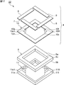
- FIG. 2 is an exploded perspective view of the drive unit according to the first embodiment of the present invention.
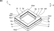
- FIG. 3 is a perspective view showing the drive unit according to the first embodiment of the present invention.
- FIG. 4 is a diagram showing the displacement amount of the portion in contact with the moving body in the first to fourth side portions when a voltage is applied to a plurality of piezoelectric elements of the drive unit of the comparative example.
- FIG. 5 shows the amount of displacement of the portion in contact with the moving body in the first to fourth side portions when a voltage is applied to the plurality of piezoelectric elements of the drive unit according to the first embodiment of the present invention.
- FIG. 6 is a perspective view showing an example of the vibration state of the laminate of the piezoelectric vibration member and the elastic member in the first embodiment of the present invention.
- FIG. 7 is a plan view of a fixing plate in a modification of the first embodiment of the present invention.
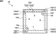
- FIG. 8 is a plan sectional view of the fixing plate according to the first embodiment of the present invention.
- FIG. 9 is a perspective view of a moving body used in the drive device according to the first embodiment of the present invention.
- FIG. 10A is a schematic diagram for explaining an initial state.
- FIG. 10B is a schematic diagram for explaining a state where the moving body is held.
- FIG. 11A and FIG. 11B are schematic views for explaining how the respective moving bodies are moved in the driving apparatus according to the first embodiment of the present invention.
- FIG. 12 is an exploded perspective view of the drive unit according to the second embodiment of the present invention.
- FIG. 1 is a perspective view of a driving apparatus according to the first embodiment of the present invention.
- FIG. 2 is an exploded perspective view of the drive unit according to the first embodiment.
- FIG. 3 is a perspective view showing the drive unit in the first embodiment.
- the drive device 1 includes a drive unit 2 and a moving body 3.
- the drive unit 2 has a rectangular frame shape.
- the drive unit 2 has first to fourth side portions 2d to 2g.
- the drive unit 2 has an elastic body 5.
- the elastic body 5 has a first main surface 5a and a second main surface 5b facing each other.
- the elastic body 5 is made of an appropriate rigid material such as ceramic or metal.
- the elastic body 5 has a rectangular frame shape.
- the elastic body 5 has a first opening 5c penetrating from the first main surface 5a toward the second main surface 5b at the center.
- the moving body 3 shown in FIG. 1 is inserted into the first opening 5c.
- the entire surface of the plurality of piezoelectric elements 6 to 9 on the side of the fixing plate 10 shown in FIG. Note that it is sufficient that at least a part of the surfaces of the plurality of piezoelectric elements 6 to 9 on the fixing plate 10 side is bonded to the fixing plate 10.
- the piezoelectric vibrating body 4 has an opening. In a plan view from the first main surface 5a side of the elastic body 5, the first opening of the elastic body 5 and the second opening 10c of the fixing plate 10 overlap.
- the piezoelectric vibrating body 4 is a laminated body of a fixed plate 10 and a plurality of piezoelectric elements 6 to 9 stacked on the fixed plate 10.
- Each of the plurality of piezoelectric elements 6 to 9 has a piezoelectric layer and electrodes provided so as to face each other with the piezoelectric layer interposed therebetween.
- the elastic body 5 vibrates by bending vibration and spreading vibration.
- a coupling mode of this bending vibration and spreading vibration is used.
- a plurality of coupled modes can be generated by adjusting the resonance frequency of the bending vibration and the spreading vibration.
- the fixing plate 10 has a second opening 10c, wiring, and a plurality of held portions 10e and 10f.
- the second opening 10 c of the fixing plate 10 overlaps the first opening 5 c of the elastic body 5.
- the moving body 3 shown in FIG. 1 is also inserted into the second opening 10c.
- the wiring of the fixed plate 10 is electrically connected to the plurality of piezoelectric elements 6-9.
- the fixed plate 10 is a circuit board and has a board 10A made of glass epoxy resin or the like. Wiring is provided on the substrate 10A.
- the material of the substrate 10A is not particularly limited. It is preferable that the fixing plate 10 is more easily displaced than the elastic body 5.
- the drive unit 2 further includes a support body 11 disposed on the second main surface 5b side of the elastic body 5.
- the piezoelectric vibrating body 4 is fixed to the support 11 by a plurality of held portions 10 e and 10 f of the fixed plate 10. More specifically, the support 11 has a plurality of protrusions 11e and 11f extending in the thickness direction. The plurality of protrusions 11 e and 11 f are located inside the first opening 5 c of the elastic body 5.
- the piezoelectric vibrating body 4 is fixed to the support 11 by joining the held portions 10e and 10f to the protruding portions 11e and 11f, respectively.
- the held portions 10e and 10f are fixed to the support 11 via a conductive bonding material such as solder or conductive paste, for example.
- connection terminals 11e1 and 11f1 are electrically connected by the conductive bonding material.
- the plurality of piezoelectric elements 6 to 9 are electrically connected to the outside via the fixed plate 10 and the support 11.
- the fixing plate 10 has two held portions 10e and 10f, and the support 11 has two protruding portions 11e and 11f.
- the fixed plate 10 is fixed to the support 11 at two locations.
- a gap A exists between the second main surface 5 b of the elastic body 5 and the surface of the support 11 on the elastic body 5 side.
- the fixing plate may have three or more held parts, and the support may have three or more protruding parts. In that case, the piezoelectric vibrator can be fixed to the support at three or more locations.
- a feature of this embodiment is that a plurality of piezoelectric elements 6 to 9 are surface-bonded to the fixed plate 10. Thereby, the vibration of the drive unit 2 is difficult to be inhibited. This will be described below using a comparative example.
- a driving device having a structure similar to that of the present embodiment was prepared except that a plurality of piezoelectric elements were electrically connected to the outside by lead wires instead of the fixing plate and the support.
- FIG. 4 is a diagram showing the displacement amount of the portion in contact with the moving body in the first to fourth side portions when a voltage is applied to the plurality of piezoelectric elements of the drive unit of the comparative example.
- FIG. 5 is a diagram showing the displacement amount of the portion in contact with the moving body in the first to fourth side portions when a voltage is applied to a plurality of piezoelectric elements of the drive unit in the first embodiment. is there.
- the solid line indicates the displacement of the first side portion
- the short-period broken line indicates the second side portion
- the alternate long and short dash line indicates the third side portion
- the two-dot chain line indicates the displacement of the fourth side portion.
- a long-period broken line indicates an applied voltage.
- the drive unit of the comparative example has a large variation in displacement between the sides.
- FIG. 5 it can be seen that in the drive unit according to the present embodiment, variation in displacement between the side portions is small. Further, in the present embodiment, it can also be seen that the displacement amount of the first to fourth side portions is large.
- the plurality of piezoelectric elements 6 to 9 shown in FIG. Therefore, all the piezoelectric elements 6 to 9 are bonded to the fixed plate 10 with a large area. Therefore, the fixed plate 10 follows the vibration of any of the piezoelectric elements 6 to 9 with high accuracy.
- the laminated body of the piezoelectric vibrating body 4 and the elastic body 5 is fixed to the support 11 by the held portions 10e and 10f of the fixing plate 10, and the plurality of piezoelectric elements 6 to 9 are electrically connected to the outside. ing. Therefore, the vibration of the drive unit 2 is not easily inhibited.
- the first to fourth side portions 2d to 2g are hardly displaced.
- the fixed plate 10 is more easily displaced than the elastic body 5. Therefore, vibration inhibition can be effectively suppressed.
- the fixing plate 10 can be made to follow the vibration of the plurality of piezoelectric elements 6 to 9 with higher accuracy, and the vibration is hardly inhibited.
- FIG. 6 is a perspective view showing an example of a vibration state of the laminate of the piezoelectric vibration member and the elastic member in the first embodiment.
- the laminated body of the piezoelectric vibrator and the elastic body has four vibration nodes B to E.
- Each vibration node B to E is located at each corner of the second opening of the fixed plate in the laminate.
- held portions 10e and 10f are provided at two corner portions 10c1 and 10c3 of the corner portions 10c1 to 10c4.
- the gap A exists between the elastic body 5 and the support body 11, the vibration is hardly inhibited.
- the piezoelectric vibrating body serves as a support body at the held portion. It is preferably fixed.
- the held portions 30e to 30h may be provided at any of the corner portions of the second opening 30c of the fixing plate 30. In this case, it is preferable that at least two of the plurality of held portions 30e to 30h are fixed to the support. Thereby, the laminated body of the piezoelectric vibrating body and the elastic body can be securely fixed, and the vibration is not easily inhibited.
- FIG. 8 is a plan sectional view of the fixing plate in the first embodiment.
- positioning of each piezoelectric element in the main surface at the side of several piezoelectric element of a fixing plate is shown with a broken line.
- the arrangement on the main surface of each connection land, which will be described later, is indicated by a chain line.
- the wiring 10d of the fixing plate 10 in the present embodiment includes a wiring 10d1 and a wiring 10d2 provided inside the substrate 10A.
- the wiring 10d1 has connection portions 10d11 and 10d12.
- the connecting portions 10d11 and 10d12 are continuously provided in the thickness direction of the fixed plate 10 and reach the main surface of the fixed plate 10 on the side of the plurality of piezoelectric elements.
- connection lands 10D11, 10D12, 10D21, and 10D22 indicated by alternate long and short dash lines are provided on the main surface of the fixed plate 10.
- the connection unit 10d11 is connected to the connection land 10D11.
- the connection land 10 ⁇ / b> D ⁇ b> 11 connects the electrode of the piezoelectric element 6 and the electrode of the piezoelectric element 7.
- connection unit 10d12 is connected to the connection land 10D12.
- the connection land 10 ⁇ / b> D ⁇ b> 12 connects the electrode of the piezoelectric element 8 and the electrode of the piezoelectric element 9.
- the wiring 10d2 has connection portions 10d21 and 10d22.
- the connecting portions 10d21 and 10d22 also reach the main surface of the fixing plate 10.
- the connection portion 10d21 is connected to the connection land 10D21.
- the connection land 10D21 connects the electrode of the piezoelectric element 6 and the electrode of the piezoelectric element 9.
- the connection unit 10d22 is connected to the connection land 10D22.
- the connection land 10 ⁇ / b> D ⁇ b> 22 connects the electrode of the piezoelectric element 7 and the electrode of the piezoelectric element 8.
- the wiring 10d1 reaches the held portion 10e. More specifically, the held portion 10e is provided with a through hole 10e1. An end of the wiring 10d1 reaching the held portion 10e is exposed to the outside through the through hole 10e1. Similarly, a through hole 10f1 is provided in the held portion 10f. The wiring 10d2 reaches the through hole 10f1, and the end of the wiring 10d2 is also exposed to the outside.
- the held portions 10e and 10f and the protruding portion of the support are joined by the conductive joining material.
- the conductive bonding material reaches the through holes 10e1 and 10f1. Thereby, the wiring 10d and the connection terminal of the support are electrically connected.
- the through-hole does not necessarily need to be provided in the held portion.
- the wiring is continuously provided in the thickness direction so as to reach the main surface on the support side.
- the piezoelectric vibrator can be more firmly fixed to the support by providing the through holes 10e1 and 10f1 in the held portions 10e and 10f as in the present embodiment.
- the wiring 10d includes the wiring 10d1 and the wiring 10d2 provided inside the substrate 10A. Note that the wiring may be provided only on the surface of the substrate. Even in this case, the wiring may be electrically connected to the plurality of piezoelectric elements and reach the through hole of the held portion.
- the moving body 3 has a cylindrical shape. That is, in the moving body 3, the side surface 3c connects the first main surface 3a and the second main surface 3b opposite to the first main surface 3a.
- the shape of the mobile body 3 is not specifically limited, For example, a substantially square pillar shape etc. may be sufficient.
- the direction connecting the first main surface 3a and the second main surface 3b is a direction Z in which the moving body 3 is moved, as will be described later.
- the moving body 3 is made of an appropriate material such as ceramics, metal, or synthetic resin.
- the bending vibration and the spreading vibration described above are generated.
- a coupling mode in which the bending vibration and the spreading vibration are coupled is used. That is, a plurality of coupling modes having different resonance frequencies appear as coupling modes of the bending vibration and the spreading vibration.
- the first coupling mode and the second coupling mode are used. The vibration in the first and second coupling modes is caused by the movable state in which the inner wall of the first opening 5c of the elastic body 5 is frictionally engaged with the moving body 3, and the inner wall of the first opening 5c is moved.
- It has a vibration state that realizes a released state that is separated from the body 3 or that is in contact with the moving body 3 with a lower frictional engagement force than the movable state. That is, in any case of the first coupling mode and the second coupling mode, a vibration state that realizes the two states is generated.
- the movable body 3 is moved to one side in the axial direction by the first coupling mode in the movable state.
- the inner wall of the first opening 5c of the elastic body 5 moves the moving body 3 backward in the movable state. That is, the moving body 3 can be moved forward or backward by switching the drive frequency so that the first coupling mode and the second coupling mode occur.
- the first and second coupling modes in which the vibration state realizing the release state and the movable state are generated are used.
- the resonance frequency of the bending vibration and the resonance frequency of the spreading vibration are matched.
- the resonance frequencies of both may not be exactly the same, and the absolute value of the difference between the resonance frequency of the bending vibration and the resonance frequency of the spread vibration is the resonance frequency in the first coupling mode and the second coupling mode. What is necessary is just to be in the range within 15% of the average value of resonance frequency.
- a coupled mode of bending vibration and spreading vibration is used, but bending vibration and coupled mode may be used. Further, bending vibration and vibration modes other than bending vibration such as spreading vibration may be used.
- FIG. 10A is a schematic diagram showing an initial state in the first embodiment.
- FIG. 10B is a schematic diagram for explaining a state where the moving body is gripped in the first embodiment.
- FIG. 11A and FIG. 11B are schematic views for explaining how the respective moving bodies are moved in the driving apparatus of the first embodiment.
- illustration of the support body is abbreviate
- the drive unit 2 is driven so as to generate the first coupling mode, so that the movable unit is brought into a movable state as shown in FIG. 10 (b). That is, the first opening 5 c of the elastic body 5 is pressed against the outer peripheral surface of the moving body 3.
- the movable body 3 can be moved forward in the direction Z1 as shown in FIG. 11A by moving in the first coupling mode.
- the forward state is stopped by realizing the release state.
- the inner wall of the first opening 5c of the elastic body 5 is displaced to the opposite side to the direction Z1 shown in FIG. ing. By repeating these steps, the moving body 3 can be pitched forward.
- the piezoelectric vibrating body 4 is surface-bonded to the first main surface 5 a of the elastic body 5. Therefore, the laminated body of the piezoelectric vibrating body 4 and the elastic body 5 is easily displaced in the direction Z from the second main surface 5b of the elastic body 5 to the first main surface 5a side. Therefore, it is easy to move the moving body 3 forward.
- the piezoelectric vibrating body 4 is surface-bonded to the elastic body 5 from the plurality of piezoelectric elements 6 to 9 side. Therefore, the plurality of piezoelectric elements 6 to 9 are located between the elastic body 5 and the fixed plate 10. Therefore, the plurality of piezoelectric elements 6 to 9 are difficult to contact the outside and are not easily damaged.
- the piezoelectric vibrating body may be provided on the second main surface of the elastic body. Also in this case, the plurality of piezoelectric elements are difficult to contact the outside and are not easily damaged.
- the moving body 3 When the moving body 3 is moved backward, the moving body 3 can be moved backward by generating the second coupling mode and driving in the second coupling mode.
- FIG. 12 is an exploded perspective view showing a drive unit according to the second embodiment of the present invention.
- the drive unit 22 is different from the first embodiment in that the piezoelectric vibrating body 4 is surface-bonded to the elastic body 5 from the fixed plate 10 side. Except for the above, the drive unit 22 and the drive device have the same configuration as that of the first embodiment.
- the vibration is not easily inhibited as in the first embodiment.
Landscapes
- General Electrical Machinery Utilizing Piezoelectricity, Electrostriction Or Magnetostriction (AREA)
Abstract
駆動部の振動が阻害され難い、駆動ユニットを提供する。 駆動ユニット2は、第1の開口部を有する弾性体5と、弾性体5の第1及び第2の主面5a及び5bの内の一方の主面に積層されており、開口部を有する圧電振動体4とを備える。圧電振動体4が、第2の開口部10cと、配線と、複数の被保持部10e,10fとを有する固定板10と、固定板10に面接着されている複数の圧電素子との積層体である。配線が複数の圧電素子に電気的に接続されており、かつ複数の被保持部10e,10fに至っている。複数の圧電素子を駆動することにより、屈曲振動と、屈曲振動とは異なる少なくとも一種の他の振動とで、または屈曲振動と、屈曲振動とは異なる少なくとも一種の他の振動が結合してなる結合モードの振動で振動するように構成されている。
Description
本発明は、圧電素子を用いた駆動ユニット及び駆動ユニットを駆動して移動体を移動させる駆動装置に関する。
従来、カメラのレンズなどを移動させる駆動装置として、圧電素子を用いた駆動装置が種々提案されている。
下記の特許文献1には、屈曲振動と他の振動を利用した超音波モーターが開示されている。ここでは、筒状の移動体が、円板状の基体の貫通孔に挿入されている。筒状の移動体は、その軸方向に移動するように構成されている。円板状の基体の両面に圧電素子が設けられている。この円板の屈曲振動と径方向振動との複合共振が用いられている。
従来、圧電素子を用いた駆動装置では、圧電素子を有する駆動部が、基板やケースなどの他の部材に機械的に保持されていた。また、駆動のために、外部と電気的に接続されていた。この機械的な保持と電気的な接続とにより、駆動部の振動が阻害されることがあった。
本発明の目的は、駆動部の振動が阻害され難い、駆動ユニット及び駆動装置を提供することにある。
本発明に係る駆動ユニットは、対向し合う第1及び第2の主面を有し、かつ前記第1の主面から前記第2の主面に向かって貫通している第1の開口部を有する弾性体と、前記弾性体の前記第1及び前記第2の主面における少なくとも一方の主面に設けられている圧電振動体とを備え、前記圧電振動体が、第2の開口部と、配線とを有する固定板と、前記固定板に面接着されている複数の圧電素子との積層体であり、前記配線が前記複数の圧電素子に電気的に接続されており、前記複数の圧電素子を駆動することにより、屈曲振動と、前記屈曲振動とは異なる少なくとも一種の他の振動とで、または前記屈曲振動と、前記屈曲振動とは異なる少なくとも一種の前記他の振動が結合してなる結合モードの振動で振動するように構成されている。
本発明に係る駆動ユニットのある特定の局面では、前記固定板に、前記複数の圧電素子の前記固定板側の全面が面接着されている。この場合には、振動がより一層阻害され難い。
本発明に係る駆動ユニットの他の特定の局面では、前記弾性体の前記第2の主面側に配置されており、かつ接続端子を有する支持体をさらに備え、前記圧電振動体が、複数の被保持部をさらに備え、前記圧電振動体と前記弾性体との前記積層体が振動の節を有し、前記固定板の前記複数の被保持部が前記振動の節に位置しており、前記複数の被保持部で前記圧電振動体が前記支持体に固定されており、前記固定板の前記配線が、前記複数の被保持部に至っており、前記接続端子と前記配線とが電気的に接続されている。この場合には、支持体を介して圧電振動体を外部に電気的に接続することができる。加えて、振動がより一層阻害され難い。
本発明に係る駆動ユニットのさらに他の特定の局面では、前記圧電振動体及び前記弾性体が矩形枠状の形状を有し、前記圧電振動体と前記弾性体との矩形枠状の積層体において、該積層体の前記振動の節が、前記固定板の前記第2の開口部のコーナー部に位置している。
本発明に係る駆動ユニットの別の特定の局面では、前記圧電振動体が前記弾性体の前記第1の主面に面接着されている。この場合には、弾性体の第2の主面から第1の主面側の方向に、圧電振動体と弾性体との積層体が変位し易い。
本発明に係る駆動ユニットのさらに別の特定の局面では、前記圧電振動体が、前記複数の圧電素子側から前記弾性体に面接着されている。この場合には、複数の圧電素子は、弾性体と固定板との間に位置している。よって、複数の圧電素子は外部に接触し難く、破損し難い。
本発明に係る駆動ユニットのさらに別の特定の局面では、前記圧電振動体が、前記固定板側から前記弾性体に面接着されている。この場合には、振動がより一層阻害され難い。
本発明に係る駆動装置は、本発明に従って構成されている駆動ユニットと、前記弾性体の前記第1の開口部に挿入されており、前記駆動ユニットを駆動することにより、前記弾性体の前記第1の主面と前記第2の主面とを結ぶ方向に移動される移動体とを備え、前記他の振動または前記結合モードの振動が、前記移動体を移動させ得るように前記弾性体の前記第1の開口部の内壁が前記移動体に摩擦係合している移動可能状態と、前記弾性体の前記第1の開口部の前記内壁が前記移動体に対して隔てられており、あるいは前記移動可能状態よりも低い摩擦係合力で前記内壁が前記移動体に接触しているリリース状態とを実現する振動姿態を有する。この場合には、振動がより一層阻害され難い。
本発明に係る駆動装置のある特定の局面では、前記駆動ユニットの前記屈曲振動及び前記他の振動により、または前記結合モードの振動により、前記移動体を移動させる。
本発明によれば、駆動部の振動が阻害され難い、駆動ユニット及び駆動装置を提供することができる。
以下、図面を参照しつつ、本発明の具体的な実施形態を説明することにより、本発明を明らかにする。
なお、本明細書に記載の各実施形態は、例示的なものであり、異なる実施形態間において、構成の部分的な置換または組み合わせが可能であることを指摘しておく。
(第1の実施形態)
図1は、本発明の第1の実施形態に係る駆動装置の斜視図である。図2は、第1の実施形態における駆動ユニットの分解斜視図である。図3は、第1の実施形態における駆動ユニットを示す斜視図である。
図1は、本発明の第1の実施形態に係る駆動装置の斜視図である。図2は、第1の実施形態における駆動ユニットの分解斜視図である。図3は、第1の実施形態における駆動ユニットを示す斜視図である。
図1に示すように、駆動装置1は、駆動ユニット2と、移動体3とを有する。
駆動ユニット2は、矩形枠状の形状を有する。駆動ユニット2は、第1~第4の辺部分2d~2gを有する。
図2に示すように、駆動ユニット2は、弾性体5を有する。弾性体5は、対向し合う第1の主面5aと、第2の主面5bとを有する。弾性体5は、セラミックスや金属などの適宜の剛性材料からなる。弾性体5は、本実施形態では、矩形枠状の形状を有する。弾性体5は、中央に、第1の主面5aから第2の主面5bに向かって貫通している第1の開口部5cを有する。この第1の開口部5cに、図1に示した移動体3が挿入されている。
図3に示すように、固定板10に、図2に示した複数の圧電素子6~9の固定板10側の全面が面接着されている。なお、固定板10には、複数の圧電素子6~9の固定板10側の面の少なくとも一部が面接着されていればよい。圧電振動体4は開口部を有する。弾性体5の第1の主面5a側からの平面視において、弾性体5の第1の開口部と固定板10の第2の開口部10cとは重なっている。
図2に戻り、圧電振動体4は、固定板10と、固定板10上に積層されている複数の圧電素子6~9との積層体である。複数の圧電素子6~9は、それぞれ、圧電体層と、圧電体層を挟んで対向するように設けられた電極を有する。複数の圧電素子6~9に交流電圧を印加することにより、弾性体5が屈曲振動と、拡がり振動で振動する。詳細は後述するが、本実施形態では、この屈曲振動と拡がり振動との結合モードを利用する。屈曲振動と拡がり振動の共振周波数を調整することにより、複数の結合モードを生じさせることができる。
固定板10は、第2の開口部10cと、配線と、複数の被保持部10e,10fとを有する。弾性体5の第1の主面5a側からの平面視において、固定板10の第2の開口部10cは、弾性体5の第1の開口部5cに重なっている。図1に示した移動体3は、第2の開口部10cにも挿入されている。
固定板10の配線は、複数の圧電素子6~9に電気的に接続されている。固定板10は回路基板であり、ガラスエポキシ樹脂などからなる基板10Aを有する。基板10Aに、配線が設けられている。なお、上記基板10Aの材料は特に限定されない。固定板10は弾性体5よりも変位し易いことが好ましい。
駆動ユニット2は、弾性体5の第2の主面5b側に配置されている、支持体11をさらに有する。圧電振動体4は、固定板10の複数の被保持部10e,10fで支持体11に固定されている。より具体的には、支持体11は、厚み方向に延びる複数の突出部11e,11fを有する。複数の突出部11e,11fは、弾性体5の第1の開口部5cの内側に位置する。被保持部10e,10fが突出部11e,11fにそれぞれ接合されることにより、圧電振動体4が支持体11に固定されている。被保持部10e,10fは、例えば、半田や導電ペーストなどの導電性接合材を介して支持体11に固定されている。
さらに、支持体11の突出部11e,11fは、接続端子11e1,11f1を有する。他方、詳細は後述するが、固定板10の配線は、被保持部10e,10fに至っている。上記導電性接合材により、配線と接続端子11e1,11f1とが電気的に接続されている。複数の圧電素子6~9は、固定板10及び支持体11を介して外部に電気的に接続される。
本実施形態では、固定板10は2箇所の被保持部10e,10fを有し、支持体11は2箇所の突出部11e,11fを有する。固定板10は、2箇所において支持体11に固定されている。図3に示されているように、弾性体5の第2の主面5bと、支持体11の弾性体5の側の面との間には、ギャップAが存在する。なお、固定板が3箇所以上の被保持部を有し、支持体が3箇所以上の突出部を有していてもよい。その場合には、圧電振動体が3箇所以上で支持体に固定され得る。
図2に示した複数の圧電素子6~9に交流電圧を印加して、駆動ユニット2を駆動することにより、図1に示した移動体3は、駆動ユニット2の厚み方向に平行な方向Zに沿って移動される。この移動操作及び移動体3の詳細は後程説明する。
本実施形態の特徴は、複数の圧電素子6~9が固定板10に面接着されていることにある。それによって、駆動ユニット2の振動が阻害され難い。これを、下記において比較例を用いて説明する。
比較例として、固定板及び支持体に代えて、リード線により複数の圧電素子が外部に電気的に接続されることを除いては、本実施形態と同様の構造の駆動装置を用意した。
図4は、比較例の駆動ユニットの複数の圧電素子に電圧を印加したときの、第1~第4の辺部分における、移動体と接触している部分の変位量を示す図である。図5は、第1の実施形態における駆動ユニットの複数の圧電素子に電圧を印加したときの、第1~第4の辺部分における、移動体と接触している部分の変位量を示す図である。なお、実線は第1の辺部分、短い周期の破線は第2の辺部分、一点鎖線は第3の辺部分、二点鎖線は第4の辺部分の変位を示す。長い周期の破線は、印加電圧を示す。
図4に示されているように、比較例の駆動ユニットでは、各辺部分間における、変位のばらつきが大きい。これに対して、図5に示されているように、本実施形態における駆動ユニットでは、各辺部分間における変位のばらつきは小さいことがわかる。さらに、本実施形態では、第1~第4の辺部分の変位量が大きいこともわかる。
図3に示されているように、本実施形態では、図2に示した複数の圧電素子6~9が固定板10に面接着されている。そのため、いずれの圧電素子6~9も、固定板10に大きい面積で接着されている。よって、固定板10は、いずれの圧電素子6~9の振動にも高精度で追従する。この固定板10の被保持部10e,10fにより、圧電振動体4及び弾性体5の積層体が支持体11に固定されており、かつ複数の圧電素子6~9が外部に電気的に接続されている。従って、駆動ユニット2の振動が阻害され難い。加えて、第1~第4の辺部分2d~2gの変位に偏りも生じ難い。
さらに、固定板10は、弾性体5よりも変位し易い。よって、振動の阻害を効果的に抑制することができる。
なお、固定板には、複数の圧電素子の固定板側の面の少なくとも一部が面接着されていればよい。もっとも、本実施形態のように、固定板10に複数の圧電素子6~9の固定板10側の全面が面接着されていることが好ましい。それによって、複数の圧電素子6~9の振動に、固定板10をより一層高精度で追従させることができ、振動がより一層阻害され難い。
図6は、第1の実施形態における圧電振動体及び弾性体の積層体の振動姿態の一例を示す斜視図である。
圧電振動体と弾性体との積層体は、4箇所の振動の節B~Eを有する。各振動の節B~Eは、上記積層体における固定板の第2の開口部の各コーナー部に位置している。図3に示すように、コーナー部10c1~10c4の内の2箇所のコーナー部10c1,10c3に、被保持部10e,10fが設けられている。このように、振動の節B,Dに設けられている被保持部10e,10fにおいて支持体11に固定されているため、振動の阻害を効果的に抑制することができる。さらに、弾性体5と支持体11との間にはギャップAが存在するため、振動が阻害され難い。
なお、固定板が被保持部を3箇所以上有する場合には、複数の被保持部の内の少なくとも2箇所が振動の節に位置しており、上記被保持部で圧電振動体が支持体に固定されていることが好ましい。例えば、図7に示す変形例のように、固定板30の第2の開口部30cのコーナー部のいずれにも被保持部30e~30hが設けられていてもよい。この場合には、複数の被保持部30e~30hの内の少なくとも2箇所で支持体に固定されていることが好ましい。それによって、圧電振動体と弾性体との積層体を確実に固定することができ、かつ振動が阻害され難い。
次に、固定板と複数の圧電素子及び支持体との電気的な接続について、より詳細に説明する。
図8は、第1の実施形態における固定板の平面断面図である。なお、破線により、固定板の複数の圧電素子側の主面における各圧電素子の配置を示す。一点鎖線により、後述する各接続ランドの上記主面における配置を示す。
本実施形態における固定板10の配線10dは、基板10Aの内部に設けられている配線10d1及び配線10d2を有する。配線10d1は、接続部10d11,10d12を有する。接続部10d11,10d12は、固定板10の厚み方向に連続的に設けられており、固定板10の複数の圧電素子側の主面に至っている。固定板10の該主面には、一点鎖線により示す接続ランド10D11,10D12,10D21,10D22が設けられている。接続部10d11は、接続ランド10D11に接続されている。接続ランド10D11は、圧電素子6の電極と圧電素子7の電極を接続している。接続部10d12は、接続ランド10D12に接続されている。接続ランド10D12は、圧電素子8の電極と圧電素子9の電極を接続している。同様に、配線10d2は、接続部10d21,10d22を有する。接続部10d21,10d22も固定板10の上記主面に至っている。接続部10d21は、接続ランド10D21に接続されている。接続ランド10D21は、圧電素子6の電極と圧電素子9の電極を接続している。接続部10d22は、接続ランド10D22に接続されている。接続ランド10D22は、圧電素子7の電極と圧電素子8の電極を接続している。
配線10d1は、被保持部10eに至っている。より具体的には、被保持部10eには、貫通孔10e1が設けられている。配線10d1の被保持部10eに至っている端部は、貫通孔10e1において外部に露出している。同様に、被保持部10fにも貫通孔10f1が設けられている。配線10d2は貫通孔10f1に至っており、配線10d2の端部も外部に露出している。
上述したように、被保持部10e,10fと支持体の突出部とは、導電性接合材により接合されている。このとき、導電性接合材は、貫通孔10e1,10f1に至っている。それによって、配線10dと支持体の接続端子とが電気的に接続されている。
なお、被保持部には、貫通孔は必ずしも設けられていなくともよい。この場合には、例えば、被保持部において、支持体側の主面に至るように、厚み方向に連続的に配線が設けられていればよい。もっとも、本実施形態のように、被保持部10e,10fに貫通孔10e1,10f1が設けられている方が、圧電振動体を支持体により一層強固に固定することができる。
本実施形態では、配線10dは、基板10Aの内部に設けられている配線10d1及び配線10d2を有する。なお、配線は、基板の表面のみに設けられていてもよい。この場合においても、配線は、複数の圧電素子に電気的に接続され、かつ被保持部の貫通孔に至っていればよい。
次に、移動体及び移動体の移動操作の詳細を説明する。
図9に示すように、移動体3は、円柱状の形状を有する。すなわち、移動体3は、第1の主面3aと、第1の主面3aと対向する第2の主面3bとを、側面3cが結んでいる。なお、移動体3の形状は特に限定されず、例えば、略四角柱状などであってもよい。
上記第1の主面3aと第2の主面3bとを結ぶ方向が、後述するように、移動体3が移動される方向Zである。
上記移動体3は、セラミックス、金属、合成樹脂などの適宜の材料からなる。
図2に示した複数の圧電素子6~9に交流電圧を印加すると、前述した屈曲振動と拡がり振動とが生じる。本実施形態ではこの屈曲振動と拡がり振動とが結合してなる結合モードを利用している。すなわち、上記屈曲振動と拡がり振動との結合モードとして、共振周波数が異なる複数の結合モードが現れる。本実施形態では、第1の結合モードと第2の結合モードとを利用する。第1,第2の結合モードの振動は、弾性体5の第1の開口部5cの内壁が移動体3に摩擦係合している移動可能状態と、第1の開口部5cの内壁が移動体3に対して隔てられており、あるいは移動可能状態よりも低い摩擦係合力で移動体3に接触しているリリース状態とを実現する振動姿態を有する。すなわち、第1の結合モード及び第2の結合モードのいずれの場合においても、上記2つの状態を実現する振動姿態が生じる。
ただし、第1の結合モードでは、移動可能状態において、上記第1の結合モードにより、上記移動体3の軸方向において一方側に移動される。これを前進とすると、第2の結合モードでは、移動可能状態において、弾性体5の第1の開口部5cの内壁が移動体3を後退させることになる。すなわち、上記第1の結合モードと第2の結合モードとが生じるように駆動周波数を切り換えることにより、移動体3を前進あるいは後退させることができる。
上記のように、本実施形態では、上記リリース状態と移動可能状態とを実現する振動姿態が生じる第1,第2の結合モードを利用する。屈曲振動と拡がり振動とを結合させるには、好ましくは、屈曲振動の共振周波数と、拡がり振動の共振周波数とが一致されていることが望ましい。もっとも、双方の共振周波数は完全に一致されずともよく、屈曲振動の共振周波数と、拡がり振動の共振周波数との差の絶対値は、第1の結合モードにおける共振周波数及び第2の結合モードにおける共振周波数の平均値の15%以内の範囲内であればよい。
なお、本実施形態では、屈曲振動と拡がり振動との結合モードを利用しているが、屈曲振動と、結合モードとを利用してもよい。また、屈曲振動と、拡がり振動などの屈曲振動以外の他の振動モードとを利用してもよい。
図10(a)は、第1の実施形態における初期状態を示す模式図である。図10(b)は、第1の実施形態において、移動体を把持した状態を説明するための模式図である。図11(a)及び図11(b)は、第1の実施形態の駆動装置において、各々移動体を移動する様子を説明するための模式図である。なお、図10(a)及び図10(b)並びに図11(a)及び図11(b)では、支持体は図示を省略してある。
図10(a)に示す初期状態から、第1の結合モードを生じるように駆動ユニット2を駆動することにより、図10(b)に示すように、移動可能状態とする。すなわち、弾性体5の第1の開口部5cが移動体3の外周面に圧接される。その状態で、上記第1の結合モードで移動させることにより、図11(a)に示すように、移動体3を方向Z1側に前進させることができる。そして、第1の結合モードにおいて、リリース状態を実現することにより、前進を停止する。なお、このとき、本実施形態では、図11(b)に示すように、弾性体5の第1の開口部5cの内壁は図11(a)に示した方向Z1とは反対側に変位している。これらの工程を繰り返すことにより、移動体3を前方にピッチ送りすることができる。
図1に戻り、本実施形態では、弾性体5の第1の主面5aに圧電振動体4が面接着されている。そのため、弾性体5の第2の主面5bから第1の主面5a側の方向Zに、圧電振動体4と弾性体5との積層体が変位し易い。よって、移動体3を前進させやすい。さらに、図2に示されているように、圧電振動体4は、複数の圧電素子6~9側から弾性体5に面接着されている。そのため、複数の圧電素子6~9は、弾性体5と固定板10との間に位置している。よって、複数の圧電素子6~9は外部に接触し難く、破損し難い。なお、圧電振動体は、弾性体の第2の主面に設けられていてもよい。この場合にも、複数の圧電素子が外部に接触し難く、破損し難い。
移動体3を後退させる場合には、第2の結合モードを発生させ、第2の結合モードにより駆動すれば、移動体3を後退させることができる。
(第2の実施形態)
図12は、本発明の第2の実施形態における駆動ユニットを示す分解斜視図である。
図12は、本発明の第2の実施形態における駆動ユニットを示す分解斜視図である。
駆動ユニット22では、圧電振動体4が固定板10側から弾性体5に面接着されている点で、第1の実施形態とは異なる。上記以外の点においては、駆動ユニット22及び駆動装置は、第1の実施形態と同様の構成を有する。
本実施形態においても、第1の実施形態と同様に、振動が阻害され難い。
1…駆動装置
2…駆動ユニット
2d~2g…第1~第4の辺部分
3…移動体
3a,3b…第1,第2の主面
3c…側面
4…圧電振動体
5…弾性体
5a,5b…第1,第2の主面
5c…第1の開口部
6~9…圧電素子
10…固定板
10A…基板
10c…第2の開口部
10c1~10c4…コーナー部
10d,10d1,10d2…配線
10d11,10d12,10d21,10d22…接続部
10D11,10D12,10D21,10D22…接続ランド
10e,10f…被保持部
10e1,10f1…貫通孔
11…支持体
11e,11f…突出部
11e1,11f1…接続端子
22…駆動ユニット
30…固定板
30c…第2の開口部
30e~30h…被保持部
2…駆動ユニット
2d~2g…第1~第4の辺部分
3…移動体
3a,3b…第1,第2の主面
3c…側面
4…圧電振動体
5…弾性体
5a,5b…第1,第2の主面
5c…第1の開口部
6~9…圧電素子
10…固定板
10A…基板
10c…第2の開口部
10c1~10c4…コーナー部
10d,10d1,10d2…配線
10d11,10d12,10d21,10d22…接続部
10D11,10D12,10D21,10D22…接続ランド
10e,10f…被保持部
10e1,10f1…貫通孔
11…支持体
11e,11f…突出部
11e1,11f1…接続端子
22…駆動ユニット
30…固定板
30c…第2の開口部
30e~30h…被保持部
Claims (9)
- 対向し合う第1及び第2の主面を有し、かつ前記第1の主面から前記第2の主面に向かって貫通している第1の開口部を有する弾性体と、
前記弾性体の前記第1及び前記第2の主面における少なくとも一方の主面に設けられている圧電振動体と、
を備え、
前記圧電振動体が、第2の開口部と、配線と、を有する固定板と、前記固定板に面接着されている複数の圧電素子との積層体であり、
前記配線が前記複数の圧電素子に電気的に接続されており、
前記複数の圧電素子を駆動することにより、屈曲振動と、前記屈曲振動とは異なる少なくとも一種の他の振動とで、または前記屈曲振動と、前記屈曲振動とは異なる少なくとも一種の前記他の振動が結合してなる結合モードの振動で振動するように構成されている、駆動ユニット。 - 前記固定板に、前記複数の圧電素子の前記固定板側の全面が面接着されている、請求項1に記載の駆動ユニット。
- 前記弾性体の前記第2の主面側に配置されており、かつ接続端子を有する支持体をさらに備え、
前記圧電振動体が、複数の被保持部をさらに備え、
前記圧電振動体と前記弾性体との前記積層体が振動の節を有し、前記固定板の前記複数の被保持部が前記振動の節に位置しており、前記複数の被保持部で前記圧電振動体が前記支持体に固定されており、
前記固定板の前記配線が、前記複数の被保持部に至っており、前記接続端子と前記配線とが電気的に接続されている、請求項1または2に記載の駆動ユニット。 - 前記圧電振動体及び前記弾性体が矩形枠状の形状を有し、前記圧電振動体と前記弾性体との矩形枠状の積層体において、該積層体の前記振動の節が、前記固定板の前記第2の開口部のコーナー部に位置している、請求項3に記載の駆動ユニット。
- 前記圧電振動体が前記弾性体の前記第1の主面に面接着されている、請求項1~4のいずれか1項に記載の駆動ユニット。
- 前記圧電振動体が、前記複数の圧電素子側から前記弾性体に面接着されている、請求項1~5のいずれか1項に記載の駆動ユニット。
- 前記圧電振動体が、前記固定板側から前記弾性体に面接着されている、請求項1~5のいずれか1項に記載の駆動ユニット。
- 請求項1~7のいずれか1項に記載の駆動ユニットと、
前記弾性体の前記第1の開口部に挿入されており、前記駆動ユニットを駆動することにより、前記弾性体の前記第1の主面と前記第2の主面とを結ぶ方向に移動される移動体と、
を備え、
前記他の振動または前記結合モードの振動が、前記移動体を移動させ得るように前記弾性体の前記第1の開口部の内壁が前記移動体に摩擦係合している移動可能状態と、前記弾性体の前記第1の開口部の前記内壁が前記移動体に対して隔てられており、あるいは前記移動可能状態よりも低い摩擦係合力で前記内壁が前記移動体に接触しているリリース状態とを実現する振動姿態を有する、駆動装置。 - 前記駆動ユニットの前記屈曲振動及び前記他の振動により、または前記結合モードの振動により、前記移動体を移動させる、請求項8に記載の駆動装置。
Priority Applications (1)
| Application Number | Priority Date | Filing Date | Title |
|---|---|---|---|
| JP2017519103A JP6493525B2 (ja) | 2015-05-15 | 2016-04-28 | 駆動ユニット及び駆動装置 |
Applications Claiming Priority (2)
| Application Number | Priority Date | Filing Date | Title |
|---|---|---|---|
| JP2015-100191 | 2015-05-15 | ||
| JP2015100191 | 2015-05-15 |
Publications (1)
| Publication Number | Publication Date |
|---|---|
| WO2016185899A1 true WO2016185899A1 (ja) | 2016-11-24 |
Family
ID=57320156
Family Applications (1)
| Application Number | Title | Priority Date | Filing Date |
|---|---|---|---|
| PCT/JP2016/063424 Ceased WO2016185899A1 (ja) | 2015-05-15 | 2016-04-28 | 駆動ユニット及び駆動装置 |
Country Status (2)
| Country | Link |
|---|---|
| JP (1) | JP6493525B2 (ja) |
| WO (1) | WO2016185899A1 (ja) |
Citations (2)
| Publication number | Priority date | Publication date | Assignee | Title |
|---|---|---|---|---|
| JPH08251954A (ja) * | 1995-03-13 | 1996-09-27 | Canon Inc | 超音波振動子 |
| JP2013201813A (ja) * | 2012-03-23 | 2013-10-03 | Murata Mfg Co Ltd | 駆動装置及びモータ |
-
2016
- 2016-04-28 WO PCT/JP2016/063424 patent/WO2016185899A1/ja not_active Ceased
- 2016-04-28 JP JP2017519103A patent/JP6493525B2/ja active Active
Patent Citations (2)
| Publication number | Priority date | Publication date | Assignee | Title |
|---|---|---|---|---|
| JPH08251954A (ja) * | 1995-03-13 | 1996-09-27 | Canon Inc | 超音波振動子 |
| JP2013201813A (ja) * | 2012-03-23 | 2013-10-03 | Murata Mfg Co Ltd | 駆動装置及びモータ |
Also Published As
| Publication number | Publication date |
|---|---|
| JPWO2016185899A1 (ja) | 2018-02-22 |
| JP6493525B2 (ja) | 2019-04-03 |
Similar Documents
| Publication | Publication Date | Title |
|---|---|---|
| JP6059300B2 (ja) | 圧電振動素子,圧電振動装置および携帯端末 | |
| TWI702740B (zh) | 超聲波換能器 | |
| US9421576B2 (en) | Vibration generating apparatus and electronic apparatus including the same | |
| US8633632B2 (en) | Vibration actuator and method for manufacturing the same | |
| KR101241030B1 (ko) | 복수의 진동전달경로를 갖는 진동 증폭형 압전진동장치 및 이를 진동수단으로 채용한 전자기기 | |
| KR102138335B1 (ko) | 진동발생장치 | |
| JP2014198329A (ja) | 圧電振動モジュール | |
| WO2015163166A1 (ja) | 振動装置 | |
| JP2019147084A (ja) | 非音響用の振動発生装置及び電子機器 | |
| JPH114027A (ja) | 圧電振動体の支持構造及びこの圧電振動体の支持構造を有する圧電トランス、ジャイロ並びに積層圧電体部品 | |
| CN112445334B (zh) | 振动面板和电子设备 | |
| JP2007103496A (ja) | コンデンサおよび基板アセンブリ | |
| JP7136318B2 (ja) | 振動装置及びその製造方法 | |
| JP6493525B2 (ja) | 駆動ユニット及び駆動装置 | |
| CN107809185B (zh) | 压电驱动装置 | |
| JP6224841B2 (ja) | 圧電素子、音響発生器、音響発生装置、電子機器 | |
| JP4830858B2 (ja) | 圧電セラミックアクチュエータ及び携帯機器 | |
| JP2016208576A (ja) | 振動波モータ | |
| WO2017145649A1 (ja) | 音響発生器およびこれを備えた電子機器 | |
| JP6406444B2 (ja) | 駆動装置 | |
| JP5890209B2 (ja) | 音響発生装置 | |
| JP6193748B2 (ja) | 圧電アクチュエータおよびこれを備えた圧電振動装置、携帯端末、音響発生器、電子機器 | |
| JP2020178178A (ja) | 圧電素子、振動デバイス及び電子機器 | |
| JP2017118424A (ja) | 音響発生器、音響発生装置および電子機器 | |
| JP5940947B2 (ja) | 圧電振動素子ならびにそれを用いた圧電振動装置および携帯端末 |
Legal Events
| Date | Code | Title | Description |
|---|---|---|---|
| 121 | Ep: the epo has been informed by wipo that ep was designated in this application |
Ref document number: 16796293 Country of ref document: EP Kind code of ref document: A1 |
|
| ENP | Entry into the national phase |
Ref document number: 2017519103 Country of ref document: JP Kind code of ref document: A |
|
| NENP | Non-entry into the national phase |
Ref country code: DE |
|
| 122 | Ep: pct application non-entry in european phase |
Ref document number: 16796293 Country of ref document: EP Kind code of ref document: A1 |