WO2016181767A1 - シールド導電路 - Google Patents
シールド導電路 Download PDFInfo
- Publication number
- WO2016181767A1 WO2016181767A1 PCT/JP2016/062301 JP2016062301W WO2016181767A1 WO 2016181767 A1 WO2016181767 A1 WO 2016181767A1 JP 2016062301 W JP2016062301 W JP 2016062301W WO 2016181767 A1 WO2016181767 A1 WO 2016181767A1
- Authority
- WO
- WIPO (PCT)
- Prior art keywords
- region
- wall
- partition wall
- electric wire
- conductive path
- Prior art date
- Legal status (The legal status is an assumption and is not a legal conclusion. Google has not performed a legal analysis and makes no representation as to the accuracy of the status listed.)
- Ceased
Links
Images


Classifications
-
- B—PERFORMING OPERATIONS; TRANSPORTING
- B60—VEHICLES IN GENERAL
- B60K—ARRANGEMENT OR MOUNTING OF PROPULSION UNITS OR OF TRANSMISSIONS IN VEHICLES; ARRANGEMENT OR MOUNTING OF PLURAL DIVERSE PRIME-MOVERS IN VEHICLES; AUXILIARY DRIVES FOR VEHICLES; INSTRUMENTATION OR DASHBOARDS FOR VEHICLES; ARRANGEMENTS IN CONNECTION WITH COOLING, AIR INTAKE, GAS EXHAUST OR FUEL SUPPLY OF PROPULSION UNITS IN VEHICLES
- B60K6/00—Arrangement or mounting of plural diverse prime-movers for mutual or common propulsion, e.g. hybrid propulsion systems comprising electric motors and internal combustion engines
- B60K6/20—Arrangement or mounting of plural diverse prime-movers for mutual or common propulsion, e.g. hybrid propulsion systems comprising electric motors and internal combustion engines the prime-movers consisting of electric motors and internal combustion engines, e.g. HEVs
- B60K6/22—Arrangement or mounting of plural diverse prime-movers for mutual or common propulsion, e.g. hybrid propulsion systems comprising electric motors and internal combustion engines the prime-movers consisting of electric motors and internal combustion engines, e.g. HEVs characterised by apparatus, components or means specially adapted for HEVs
-
- B—PERFORMING OPERATIONS; TRANSPORTING
- B60—VEHICLES IN GENERAL
- B60R—VEHICLES, VEHICLE FITTINGS, OR VEHICLE PARTS, NOT OTHERWISE PROVIDED FOR
- B60R16/00—Electric or fluid circuits specially adapted for vehicles and not otherwise provided for; Arrangement of elements of electric or fluid circuits specially adapted for vehicles and not otherwise provided for
- B60R16/02—Electric or fluid circuits specially adapted for vehicles and not otherwise provided for; Arrangement of elements of electric or fluid circuits specially adapted for vehicles and not otherwise provided for electric constitutive elements
-
- H—ELECTRICITY
- H01—ELECTRIC ELEMENTS
- H01B—CABLES; CONDUCTORS; INSULATORS; SELECTION OF MATERIALS FOR THEIR CONDUCTIVE, INSULATING OR DIELECTRIC PROPERTIES
- H01B7/00—Insulated conductors or cables characterised by their form
- H01B7/17—Protection against damage caused by external factors, e.g. sheaths or armouring
-
- H—ELECTRICITY
- H02—GENERATION; CONVERSION OR DISTRIBUTION OF ELECTRIC POWER
- H02G—INSTALLATION OF ELECTRIC CABLES OR LINES, OR OF COMBINED OPTICAL AND ELECTRIC CABLES OR LINES
- H02G3/00—Installations of electric cables or lines or protective tubing therefor in or on buildings, equivalent structures or vehicles
- H02G3/02—Details
- H02G3/04—Protective tubing or conduits, e.g. cable ladders or cable troughs
-
- H—ELECTRICITY
- H05—ELECTRIC TECHNIQUES NOT OTHERWISE PROVIDED FOR
- H05K—PRINTED CIRCUITS; CASINGS OR CONSTRUCTIONAL DETAILS OF ELECTRIC APPARATUS; MANUFACTURE OF ASSEMBLAGES OF ELECTRICAL COMPONENTS
- H05K9/00—Screening of apparatus or components against electric or magnetic fields
Definitions
- the technology described in this specification relates to a shield conductive path.
- a shield conductive path in which a plurality of non-shielded electric wires are inserted into a metal pipe to shield and protect the electric wires (for example, Patent Document 1).
- a plurality of types of electric wires such as a power wire through which a high voltage and a large current flow and a weak electric wire are routed.
- a power wire and a weak electric wire are routed.
- shield the braided wire etc. on the weak electric wire to prevent the influence of electromagnetic noise generated by the power wire.
- the number of parts is increased, and processing is troublesome.
- the technology described in the present specification has been completed based on the above-described circumstances, and a shield conductive path capable of inserting a plurality of types of electric wires and easily processed into a desired shape is provided.
- the purpose is to provide.
- the technology described in the present specification is a shield conductive path including a plurality of electric wires formed by surrounding a conductor with an insulating coating, and a metal pipe that shields and protects by inserting the electric wires.
- the pipe has a cylindrical tube body through which the electric wire is inserted, and a partition wall extending from an inner wall of the tube body and partitioning the inside of the tube body into a first region and a second region, Of the partition wall, the portions near both ends located in the vicinity of the inner wall of the cylinder body are a pair of end convex portions bent in a convex shape in the direction from the first region toward the second region.
- a concave portion bent in a concave shape in the direction from the first region toward the second region is formed between the pair of end convex portions in the partition wall, and the inner wall of the cylinder body Projecting inward of the cylinder body Rutotomoni ribs extending in the axial direction of said barrel body is formed.
- the inside of the cylinder main body is divided into the first region and the second region by the partition wall. For this reason, an electric wire can be easily shielded, without taking a shield measure separately with respect to an electric wire by inserting an electric wire in each of the 1st field and the 2nd field.
- the partition wall includes a pair of end convex portions and a concave portion, at least one of the end convex portion or the concave portion is bent even when the pipe is bent from any direction. As a result, the pipe can be bent easily.
- corrugated shape is formed in the inside of a 1st area
- This uneven shape prevents the electric wire from rolling freely inside the cylinder body. Thereby, since it is suppressed that an electric wire collides inside a cylinder main body, or an electric wire collides with the inner wall of a cylinder main body, an electric wire can be protected reliably.
- the technology described in the present specification is a shield conductive path including a plurality of electric wires formed by surrounding a conductor with an insulating coating, and a metal pipe that shields and protects by inserting the electric wires.
- the pipe has a cylindrical tube body through which the electric wire is inserted, and a partition wall extending from an inner wall of the tube body and partitioning the inside of the tube body into a first region and a second region, Of the partition wall, the portions near both ends located in the vicinity of the inner wall of the cylinder body are a pair of end convex portions bent in a convex shape in the direction from the first region toward the second region.
- a concave portion bent in a concave shape in the direction from the first region toward the second region is formed between the pair of end convex portions in the partition wall, and the inner wall of the cylinder body Projecting inward of the cylinder body Ribs extending in the axial direction of said barrel body is formed with.
- the inside of the cylinder main body is divided into the first region and the second region by the partition wall. For this reason, an electric wire can be easily shielded, without taking a shield measure separately with respect to an electric wire by inserting an electric wire in each of the 1st field and the 2nd field.
- the partition wall includes a pair of end convex portions and a concave portion, at least one of the end convex portion or the concave portion is bent even when the pipe is bent from any direction. As a result, the pipe can be bent easily.
- corrugated shape is formed in the inside of a 1st area
- This uneven shape prevents the electric wire from rolling freely inside the cylinder body. Thereby, since it is suppressed that an electric wire collides inside a cylinder main body, or an electric wire collides with the inner wall of a cylinder main body, an electric wire can be protected reliably.
- the radius of curvature of the end convex portion is set to be equal to or larger than the radius of the electric wire inserted into the first region.
- an electric wire fits into the part by the side of the 1st area
- the rib is provided on an inner wall of the cylinder body located in the second region, and the rib is formed at a position facing the end convex portion of the partition wall. Yes.
- the space between the rib and the end convex portion is narrower than other portions. Therefore, it can suppress that an electric wire passes between a rib and an edge convex part, and rolls.
- the interval between the rib and the end convex portion is set to be smaller than the diameter of the electric wire inserted into the second region.
- the partition wall is formed with an intermediate convex portion that is different from the convex portion at the end and is bent in a convex shape in the direction from the first region to the second region.
- the rib is formed at a position facing the intermediate convex portion.
- the space between the rib and the intermediate convex portion is narrower than other portions. Therefore, it can suppress that an electric wire passes between a rib and an intermediate
- the first electric wire inserted into the first region among the plurality of electric wires and the second electric wire inserted into the second region among the plurality of electric wires are different in type.
- the inner wall of the cylinder body on the first area side and the wall surface on the first area side of the partition wall are smoothly connected, and the cylinder body on the second area side.
- the inner wall and the wall surface on the second region side of the partition wall are smoothly connected.
- the boundary part of the inner wall of a cylinder main body and a partition wall is connected smoothly. Thereby, it can suppress that stress concentrates on the boundary part of the inner wall of a cylinder main body, and a partition wall.
- the boundary part is smoothly connected means that the curvature of the inner wall of a cylinder main body and the curvature of the wall surface of a partition wall are changing continuously.
- the shield conductive path 110 is disposed in a vehicle 111 such as an electric vehicle or a hybrid vehicle.
- An engine room is provided in the front portion of the vehicle body 112 of the vehicle 111.
- a motor 113, an inverter 114 constituting a power circuit for driving the motor 113, and a gasoline-driven engine 115 are accommodated.
- a battery 116 constituting a power circuit is mounted on the rear portion of the vehicle body 112.
- a shield conductive path 110 and an in-vehicle conductive path 117A are routed.
- an in-vehicle conductive path 117B is routed between the inverter 114 and the motor 113.
- the shield conductive path 110 has a configuration in which two types of non-shield type electric wires 118 and 119 are inserted into a pipe 120 having both a collective shield function and an electric wire protection function.
- first electric wires 118 are arranged in the upper first region 121 (details will be described later) in FIG. 2, and one in the lower second region 122 in FIG. 2.
- the second electric wire 119 is arranged, and these are collectively referred to as two types of electric wires 118 and 119.
- the two types of electric wires 118 and 119 have different cross-sectional diameters, and the first electric wire 118 has a smaller cross-sectional diameter than the second electric wire 119.
- Each of the two types of electric wires 118 and 119 has a form in which the outer periphery of a conductor 123A, 123B made of metal (for example, aluminum alloy, aluminum, copper, copper alloy, etc.) is surrounded by insulating coatings 124A, 124B made of synthetic resin. .
- the conductors 123A and 123B of the two types of electric wires 118 and 119 are each formed of a stranded wire in which a plurality of fine wires are close to each other in a spiral shape, and are formed in a substantially circular cross section.
- the cross-sectional shape of the outer periphery of the insulating coatings 124A and 124B is also formed into a substantially circular cross-section, similar to the conductors 123A and 123B.
- the conductors 123A and 123B of the two types of electric wires 118 and 119 may be composed of rod-shaped single core wires.
- the first electric wire 118 and the second electric wire 119 are of different types.
- one of the first electric wire 118 and the second electric wire 119 may be a high-voltage electric wire and the other may be a low-voltage electric wire.
- the first electric wire 118 is a high voltage system
- the second electric wire 119 is a low voltage system.
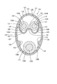
- the pipe 120 is made of metal (for example, aluminum alloy, copper alloy, stainless steel, etc.), and has a cylindrical main body 125 having a substantially circular cross-sectional cylindrical shape, and an inner wall 127 of the cylindrical main body 125 extending from the inner wall 126 of the cylindrical main body 125. And a partition wall 128 for partitioning.
- the cylinder main body 125 and the partition wall 128 are integrally formed by extrusion molding.
- the metal which comprises the pipe 120 can select arbitrary metals as needed. Further, a plated layer or a paint layer may be formed on the outer surface or the inner surface of the pipe 120 as necessary.
- the partition wall 128 is formed over the entire length of the pipe 120, and is formed from one end of the inner wall 126 of the cylinder body 125 to the inner wall 126 facing the one end.
- the cross-sectional shape of the partition wall 128 in the direction perpendicular to the axial direction of the cylinder main body 125 (the direction penetrating the paper surface of FIG. 2) is a gently curved shape as shown in FIG.
- the interior 127 of the cylinder main body 125 is partitioned into a first region 121 and a second region 122 by a partition wall 128.
- the first region 121 and the second region 122 are spaces surrounded by the inner wall 126 of the cylinder body 125 and the partition wall 128.
- a first electric wire 118 is inserted into the first region 121 from an opening on one end side of the pipe 120.
- the second electric wire 119 is inserted into the second region 122 from the opening on one end side of the pipe 120.
- the upper space in the drawing through which the first electric wire 118 is inserted is referred to as a first region 121
- the lower space in the drawing through which the second electric wire 119 is inserted is referred to as a second region 122.
- a gap 129 ⁇ / b> A is formed between the insulating coating 124 ⁇ / b> A of the first electric wire 118 inserted into the first region 121, the partition wall 128, and the inner wall 126 of the cylinder main body 125.
- a gap 129 ⁇ / b> B is also formed between the insulating coating 124 ⁇ / b> B of the second electric wire 119 inserted into the second region 122, the partition wall 128, and the inner wall 126 of the tube main body 125.
- a part of the partition wall 128 near the left and right ends in FIG. 2 has a pair of shapes bent convexly downward (in the direction from the first region 121 to the second region 122). It is made into the edge part convex-shaped part 130 of this.
- the end convex portion 130 is formed in a region in the vicinity of a portion of the partition wall 128 where the partition wall 128 extends from the inner wall 126 of the cylinder body 125.
- the radius of curvature RA of the end convex portion 130 is set to be equal to the radius RB of the first electric wire 118 or larger than the radius RB of the first electric wire 118.
- the radius of curvature RA of the end convex portion 130 is set larger than the radius RB of the first electric wire 118.
- the radius RB of the first electric wire 118 refers to the outer diameter of the insulation coating 124A covered with the conductor 123A.
- the radius of curvature RA of the pair of end convex portions 130 is set to the same value.
- the curvature radius RA of a pair of edge part convex part 130 may be set to a different value.
- the inner wall 126 of the cylinder body 125 on the first region 121 side and the wall surface on the first region 121 side of the partition wall 128 are connected by a smooth curved surface 131. Thereby, the inner wall 126 of the cylinder main body 125 and the wall surface by the side of the 1st area
- region 121 among the edge part convex parts 130 are connected smoothly. In other words, no clear boundary line or step is formed between the inner wall 126 of the cylinder main body 125 and the wall surface on the first region 121 side of the end convex portion 130.
- the partition wall 128 has a shape bent in a concave shape from above to below (a direction from the first region 121 to the second region 122) between the pair of end convex portions 130.
- a concave portion 132 is formed.
- the concave portion 132 is formed in the vicinity of an intermediate position between the pair of end convex portions 130 in the partition wall 128.
- the pair of end convex portions 130 and the concave portion 132 are connected by a smooth curved surface 134.
- a clear boundary line or step is not formed between the pair of end convex portions 130 and the concave portion 132 on the wall surface of the partition wall 128 on the first region 121 side.
- Two ribs 133 projecting inward of the cylinder body 125 are formed on the inner wall 126 of the cylinder body 125 located on the second region 122 side.
- the rib 133 is formed so as to extend in the axial direction of the cylinder main body 125 (direction passing through the paper surface in FIG. 2), and is formed over the entire length of the cylinder main body 125.
- the cylinder body 125 and the rib 133 are integrally formed by extrusion molding.
- the region located between the vertices of the two ribs 133 in the inner wall 126 of the cylinder body 125 is connected by a smooth curved surface 135. Further, with respect to the two ribs 133, the two ribs 133 and the inner wall 126 of the cylinder main body 125 are connected by a smooth curved surface 136 in the outer region in the left-right direction in FIG. 2. Thus, a clear boundary line or step is not formed between the two ribs 133 and the inner wall 126 of the cylinder body 125.
- Each of the two ribs 133 is formed at a position facing the end convex portion 130 formed on the partition wall 128.
- the distance between the apex of the rib 133 and the end convex portion 130 is set to be smaller than the diameter (outer diameter dimension) of the second electric wire 119 (see FIG. 3).
- the second electric wire 119 cannot pass through the space between the rib 133 and the end convex portion 130.
- the inner wall 126 of the cylinder main body 125 on the second region 122 side and the wall surface on the second region 122 side of the partition wall 128 are connected by a smooth curved surface 137. In other words, no clear boundary line or step is formed between the inner wall 126 of the cylinder main body 125 on the second region 122 side and the wall surface on the second region 122 side of the partition wall 128.
- two types of electric wires 118 and 119 are inserted into the inside 127 of the tube main body 125 of the pipe 120.
- Two first electric wires 118 are inserted into the first region 121 from the opening on one end side of the pipe 120, and one second electric wire 119 is inserted into the second region 122.
- the pipe 120 is bent.
- the bending process with respect to the pipe 120 may be performed before the two types of electric wires 118 and 119 are inserted.
- FIG. 4 shows an example in which the pipe 120 is bent in such a manner that the diameter of the pipe 120 is reduced in the direction orthogonal to the partition wall 128 (the vertical direction in FIG. 4).
- the diameter of the pipe 120 is reduced in the direction orthogonal to the partition wall 128 (the vertical direction in FIG. 4).
- the diameter of the pipe 120 is increased in the left-right direction in FIG.
- the partition wall 128 is deformed so that the end convex portion 130 follows the pipe 120 and has a smaller curvature.
- the concave portion 132 is deformed so that the curvature is increased because the compressive force from the pair of end convex portions 130 acts.
- FIG. 5 an example is shown in which the pipe 120 is bent in such a manner that the diameter of the pipe 120 is increased in a direction orthogonal to the partition wall 128 (vertical direction in FIG. 5).
- the diameter of the pipe 120 is increased in the direction orthogonal to the partition wall 128 (the vertical direction in FIG. 5).
- the pipe 120 is reduced in diameter in the left-right direction in FIG. In this case, since the compressive force acts on the partition wall 128, the end convex portion 130 and the concave portion 132 are deformed so that the curvature becomes large.
- the interior 127 of the cylinder main body 125 is partitioned into a first region 121 and a second region 122 by a partition wall 128.
- the electric wires 118 and 119 are inserted into the first region 121 and the second region 122, respectively, so that the electric wires 118 and 119 can be easily shielded without individually taking measures for shielding the electric wires 118 and 119. can do.
- the partition wall 128 has a pair of end convex portions 130 and a concave portion 132, at least one of the end convex portions 130 or the concave portions 132, even when the pipe 120 is bent from any direction. However, it is designed to bend according to the applied force. As a result, the pipe 120 can be bent easily.
- the inside 127 of the first region 121 and the inside 127 of the second region 122 are formed by the rib 133 formed on the inner wall 126 of the cylinder body 125, the end convex portion 130, and the concave portion 132 of the partition wall 128.
- a concave-convex shape is formed. Due to this uneven shape, the electric wires 118 and 119 are prevented from rolling freely inside the cylinder body 125. This prevents the electric wires 118 and 119 from colliding with each other in the inside 127 of the tube main body 125 and the electric wires 118 and 119 and the inner wall 126 of the tube main body 125 from colliding with each other. Can be protected.
- the radius of curvature RA of the end convex portion 130 is the same as the radius RB of the first electric wire 118 inserted into the first region 121 or the radius RB of the first electric wire 118. Is set larger than. Thereby, as shown in FIG.2 and FIG.3, it is suppressed that the 1st electric wire 118 fits into the part by the side of the 1st area
- the first electric wire 118 has a gap 129 ⁇ / b> A between the inner wall 126 of the cylinder body 125 and the partition wall 128 in the first region 121. Has been arranged. Further, even when the pipe 120 is bent in the manner shown in FIG. 5, the first electric wire 118 has a gap between the inner wall 126 of the cylinder body 125 and the partition wall 128 in the first region 121. It is arranged with 129A.
- the rib 133 is provided on the inner wall 126 of the cylinder main body 125 located in the second region 122, and the rib 133 is located at a position facing the end convex portion 130 of the partition wall 128. Is formed. Thereby, in 2nd area
- the interval between the rib 133 and the end convex portion 130 is set to be smaller than the diameter of the second electric wire 119 inserted through the second region 122. Therefore, it can suppress reliably that the 2nd electric wire 119 passes between the rib 133 and the edge convex part 130, and rolls (refer FIG. 3).
- the first electric wire 118 inserted into the first region 121 among the plurality of electric wires 118 and 119 and the second electric wire inserted into the second region 122 among the plurality of electric wires 118 and 119. 119 is different in type. Thereby, different types of electric wires 118 and 119 are inserted through the first region 121 and the second region 122, respectively, so that a plurality of types of electric wires 118 and 119 can be shielded without taking individual shielding measures. Can do.
- the inner wall 126 of the cylinder main body 125 on the first region 121 side and the wall surface on the first region 121 side of the partition wall 128 are connected by the smooth curved surface 131, and the second The inner wall 126 of the cylinder main body 125 on the region 122 side and the wall surface on the second region 122 side of the partition wall 128 are connected by a smooth curved surface 137.
- the boundary portion between the inner wall 126 of the cylinder main body 125 and the partition wall 128 is connected by the curved surfaces 131 and 137. Thereby, it can suppress that stress concentrates on the boundary part of the inner wall 126 of the cylinder main body 125, and the partition wall 128.
- FIG. As a result, when bending the pipe 120, it is not necessary to strictly consider the strength of the boundary portion between the inner wall 126 of the cylinder main body 125 and the partition wall 128, so that the pipe 120 can be easily bent. Can do.
- a gap 129 ⁇ / b> A is formed between the insulation coating of the first electric wire 118 and the inner wall 126 of the cylinder main body 125 and the wall surface on the first region 121 side of the partition wall 128. Further, a gap 129 ⁇ / b> B is also formed between the second electric wire 119 and the wall surface on the second region 122 side of the inner wall 126 and the partition wall 128 of the cylinder main body 125. Thereby, it can be easily bent without damaging each insulation coating 124A, 124B of the electric wires 118, 119.
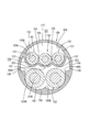
- the shield conductive path 150 according to the second embodiment will be described with reference to FIG.
- two concave portions 154 are formed between the pair of end convex portions 153 in the partition wall 152 formed in the pipe 151.
- the curvature radii of the two concave portions 154 are set to the same value. Note that the curvature radii of the two concave portions 154 may be set to different values.
- partition wall 152 is different from the end convex portion 153 between the two concave portions 154, and is downward in FIG. 6 (direction from the first region 155 to the second region 156).
- An intermediate convex portion 157 bent in a convex shape is formed.
- the intermediate convex portion 157 is formed by extrusion molding.
- Three ribs 160A, 160B, 160C projecting inward of the cylinder main body 158 are formed on the inner wall 159 of the cylinder main body 158 located on the second region 156 side.
- the ribs 160 ⁇ / b> A, 160 ⁇ / b> B, and 160 ⁇ / b> C are formed to extend in the axial direction of the cylinder main body 158 (direction passing through the paper surface in FIG. 6), and are formed over the entire length of the cylinder main body 158.
- the cylinder body 158 and the ribs 160A, 160B, 160C are integrally formed by extrusion molding.
- the two ribs 160 ⁇ / b> A and 160 ⁇ / b> C located at both left and right ends are respectively arranged to face the two end convex portions 153 formed on the partition wall 152. Further, the rib 160 ⁇ / b> B formed near the center in the left-right direction in FIG. 6 is disposed to face the intermediate convex portion 157 formed on the partition wall 152.
- first electric wires 161 are inserted in the first area 155.
- second electric wires 162 are inserted into the second region 156.
- the partition wall 152 has an intermediate convex portion 157 that is different from the end convex portion 153 and is bent in a convex shape in the direction from the first region 155 to the second region 156.
- the rib 160B is formed at a position facing the intermediate convex portion 157. Thereby, in the 2nd field 156, between rib 160B and middle convex part 157 is narrow compared with other parts. Thereby, it can suppress that the 2nd electric wire 162 passes between the rib 160B and the intermediate
- the end convex portion, the intermediate convex portion, and the concave portion are smoothly curved when viewed from the axial direction of the pipe. It may be a bent shape having a vertex as viewed from the direction, or may have both a smoothly curved shape and a bent shape.
- the rib is formed in the second region.
- the present invention is not limited to this, and the rib may be formed in the first region.
- the inner wall 126 of the cylinder body 125 and the partition wall 128 are connected by the smooth curved surfaces 131 and 137.
- the present invention is not limited to this, and the inner wall 126 of the cylinder body 125, A boundary line or a step may be formed between the partition wall 128 and the partition wall 128.
- two or three ribs are formed on the inner wall of the cylinder body.
- the present invention is not limited to this, and one rib is formed on the inner wall of the cylinder body.
- a configuration in which a plurality of four or more are formed may be used.
- one intermediate convex portion 157 is formed, but the present invention is not limited to this, and two or more intermediate convex portions 157 may be formed.
- one or two concave portions are formed.
- the present invention is not limited to this, and three or more concave portions may be formed.
- two or three electric wires are inserted into the first region.
- the present invention is not limited to this, and a configuration in which four or more electric wires are inserted may be used.
- one or two electric wires are inserted into the second region.
- the present invention is not limited to this, and a configuration in which three or more electric wires are inserted may be used.
- the rib is configured to be formed at a position facing the end convex portion or the intermediate convex portion.
- the rib is not limited thereto, and the rib may be arbitrarily formed as necessary. Can be formed in position.
- the pipe is bent.
- the present invention is not limited to this, and the pipe may be bent.
- the interval between the rib 133 and the end convex portion 130 is set to be smaller than the outer diameter of the second electric wire 119, but is not limited thereto, and the rib 133 is not limited thereto.
- the distance between the end convex portion 130 and the outer diameter of the second electric wire 119 may be set to be the same as or larger than the outer diameter of the second electric wire 119.
- the interval between the rib 160B and the intermediate convex portion 157 is set to be larger than the diameter of the second electric wire 162 inserted through the second region 156, but is not limited thereto.
- the interval between the rib 160B and the intermediate convex portion 157 may be set to be the same as the diameter of the second electric wire 162 inserted through the second region 156 or smaller than the diameter of the second electric wire 162. Thereby, it can suppress reliably that the 2nd electric wire 162 passes between between the rib 160B and the intermediate
Landscapes
- Engineering & Computer Science (AREA)
- Mechanical Engineering (AREA)
- Architecture (AREA)
- Combustion & Propulsion (AREA)
- Transportation (AREA)
- Chemical & Material Sciences (AREA)
- Microelectronics & Electronic Packaging (AREA)
- Civil Engineering (AREA)
- Structural Engineering (AREA)
- Details Of Indoor Wiring (AREA)
- Hybrid Electric Vehicles (AREA)
- Shielding Devices Or Components To Electric Or Magnetic Fields (AREA)
- Insulated Conductors (AREA)
Abstract
パイプ120は、電線118,119を挿通させる筒状の筒本体125と、筒本体125の内壁126から延出され筒本体125の内部127を第1領域121及び第2領域122に仕切る仕切り壁128と、を有し、仕切り壁128のうち、筒本体125の内壁126の近傍に位置する両端部寄りの部分は、第1領域121から第2領域122に向かう方向について凸状に曲がった一対の端部凸状部130とされており、仕切り壁128のうち一対の端部凸状部130の間には、第1領域121から第2領域122に向かう方向について凹状に曲がった凹状部132が形成されており、筒本体125の内壁126には、筒本体125の内方に突出すると共に筒本体125の軸方向に延びるリブ133が形成されている。
Description
本明細書に記載された技術は、シールド導電路に関する。
従来より、複数本のノンシールド電線を金属製のパイプに挿通することで、電線をシールドするとともに保護するようにしたシールド導電路が知られている(例えば特許文献1)。
ところで、ハイブリッド自動車などの車両においては、高電圧大電流が流れる動力電線や弱電系の電線など複数種の電線が配索される。ここで、例えば、動力電線と弱電系の電線とを、同一のパイプに挿通させる場合には、動力電線が発する電磁ノイズの影響を防ぐために弱電系の電線に編組線などのシールドを施してからパイプに挿通させる必要があり、部品点数が多くなり、かつ、加工の手間がかかるという問題があった。
この問題について検討した結果、パイプの内部を扁平な仕切り壁により2以上に分けることにより上記問題を解決可能であるとの知見が得られた。しかしながら、このような構成のパイプを配索箇所に応じた形状とするために曲げ加工を施すと、仕切り壁が梁として作用し、意図した形状に変形させるのが困難であるという問題があった。
本明細書に記載された技術は上記のような事情に基づいて完成されたものであって、複数種の電線を挿通可能であり、かつ、所望の形状に容易に加工可能なシールド導電路を提供することを目的とする。
本明細書に記載された技術は、導体を絶縁被覆で包囲してなる複数の電線と、前記電線を挿通させることによりシールドするとともに保護する金属製のパイプと、を備えるシールド導電路であって、前記パイプは、前記電線を挿通させる筒状の筒本体と、前記筒本体の内壁から延出され前記筒本体の内部を第1領域及び第2領域に仕切る仕切り壁と、を有し、前記仕切り壁のうち、前記筒本体の内壁の近傍に位置する両端部寄りの部分は、前記第1領域から前記第2領域に向かう方向について凸状に曲がった一対の端部凸状部とされており、前記仕切り壁のうち前記一対の端部凸状部の間には、前記第1領域から前記第2領域に向かう方向について凹状に曲がった凹状部が形成されており、前記筒本体の内壁には、前記筒本体の内方に突出すると共に前記筒本体の軸方向に延びるリブが形成されている。
本明細書に記載された技術によれば、筒本体の内部が仕切り壁によって第1領域、及び第2領域に仕切られている。このため、第1領域と、第2領域のそれぞれに電線を挿通することにより、電線に対して個別にシールド対策を施すことなく、容易に電線をシールドすることができる。
仕切り壁は、一対の端部凸状部と、凹状部を有するので、いかなる方向からパイプが曲げられた場合でも、端部凸状部、又は凹状部の少なくとも一方が曲がるようになっている。この結果、パイプを容易に曲げることができる。
また、筒本体の内壁に形成されたリブと、仕切り壁の端部凸状部、及び凹状部とによって、第1領域の内部、及び第2領域の内部には、凹凸形状が形成されている。この凹凸形状により、電線が筒本体の内部を自由に転がることが抑制される。これにより、筒本体の内部で電線同士が衝突したり、電線と筒本体の内壁とが衝突したりすることが抑制されるので、電線を確実に保護することができる。
本明細書に記載された技術によれば、複数種の電線を挿通可能であり、かつ、所望の形状に容易に加工可能なシールド導電路を提供することができる。
<実施形態の概要>
本明細書に記載された技術は、導体を絶縁被覆で包囲してなる複数の電線と、前記電線を挿通させることによりシールドするとともに保護する金属製のパイプと、を備えるシールド導電路であって、前記パイプは、前記電線を挿通させる筒状の筒本体と、前記筒本体の内壁から延出され前記筒本体の内部を第1領域及び第2領域に仕切る仕切り壁と、を有し、前記仕切り壁のうち、前記筒本体の内壁の近傍に位置する両端部寄りの部分は、前記第1領域から前記第2領域に向かう方向について凸状に曲がった一対の端部凸状部とされており、前記仕切り壁のうち前記一対の端部凸状部の間には、前記第1領域から前記第2領域に向かう方向について凹状に曲がった凹状部が形成されており、前記筒本体の内壁には、前記筒本体の内方に突出すると共に前記筒本体の軸方向に延びるリブが形成されている。
本明細書に記載された技術は、導体を絶縁被覆で包囲してなる複数の電線と、前記電線を挿通させることによりシールドするとともに保護する金属製のパイプと、を備えるシールド導電路であって、前記パイプは、前記電線を挿通させる筒状の筒本体と、前記筒本体の内壁から延出され前記筒本体の内部を第1領域及び第2領域に仕切る仕切り壁と、を有し、前記仕切り壁のうち、前記筒本体の内壁の近傍に位置する両端部寄りの部分は、前記第1領域から前記第2領域に向かう方向について凸状に曲がった一対の端部凸状部とされており、前記仕切り壁のうち前記一対の端部凸状部の間には、前記第1領域から前記第2領域に向かう方向について凹状に曲がった凹状部が形成されており、前記筒本体の内壁には、前記筒本体の内方に突出すると共に前記筒本体の軸方向に延びるリブが形成されている。
本明細書に記載された技術によれば、筒本体の内部が仕切り壁によって第1領域、及び第2領域に仕切られている。このため、第1領域と、第2領域のそれぞれに電線を挿通することにより、電線に対して個別にシールド対策を施すことなく、容易に電線をシールドすることができる。
仕切り壁は、一対の端部凸状部と、凹状部を有するので、いかなる方向からパイプが曲げられた場合でも、端部凸状部、又は凹状部の少なくとも一方が曲がるようになっている。この結果、パイプを容易に曲げることができる。
また、筒本体の内壁に形成されたリブと、仕切り壁の端部凸状部、及び凹状部とによって、第1領域の内部、及び第2領域の内部には、凹凸形状が形成されている。この凹凸形状により、電線が筒本体の内部を自由に転がることが抑制される。これにより、筒本体の内部で電線同士が衝突したり、電線と筒本体の内壁とが衝突したりすることが抑制されるので、電線を確実に保護することができる。
シールド導電路においては、前記端部凸状部の曲率半径は、前記第1領域内に挿通された電線の半径と同じか、又は、前記電線の半径よりも大きく設定されている。
上記の態様によれば、電線が端部凸状部の第1領域側の部分に嵌り込むことが抑制される。これにより、パイプが曲げられた時に、電線が凸状部の第1領域側の部分に嵌り込んで圧縮されることが抑制される。この結果、パイプが曲げ加工された場合において、電線を保護することができる。
シールド導電路においては、前記リブは、前記第2領域に位置する前記筒本体の内壁に設けられており、前記リブは、前記仕切り壁の前記端部凸状部と対向する位置に形成されている。
上記の態様によれば、第2領域において、リブと端部凸状部との間は、他の部分に比べて狭くなっている。これにより、電線がリブと端部凸状部との間を通り抜けて転がることを抑制することができる。
シールド導電路においては、前記リブと前記端部凸状部との間隔は、前記第2領域に挿通された電線の直径よりも小さく設定されている。
上記の態様によれば、電線がリブと端部凸状部との間を通り抜けて転がることを確実に抑制することができる。
シールド導電路においては、前記仕切り壁には、前記端部凸状部とは異なるものであって、前記第1領域から前記第2領域に向かう方向について凸状に曲がった中間凸状部が形成されており、前記リブは、前記中間凸状部と対向する位置に形成されている。
上記の態様によれば、第2領域において、リブと中間凸状部との間は、他の部分に比べて狭くなっている。これにより、電線がリブと中間凸状部との間を通り抜けて転がることを抑制することができる。
シールド導電路においては、前記複数の電線のうち前記第1領域に挿通された第1電線と、前記複数の電線のうち前記第2領域に挿通された第2電線と、は、種類が異なる。
上記の態様によれば、異なる種類の電線を、第1領域と、第2領域のそれぞれ挿通させることにより、複数種の電線に対してシールド対策を施すことなくシールドすることができる。
シールド導電路においては、前記第1領域側の前記筒本体の内壁と、前記仕切り壁のうち前記第1領域側の壁面とは、滑らかに連結されており、前記第2領域側の前記筒本体の内壁と、前記仕切り壁のうち前記第2領域側の壁面とは、滑らかに連結されている。
パイプを曲げた時に、筒本体の内壁と、仕切り壁との境界部分には応力が集中しやすくなっている。本態様によれば、筒本体の内壁と、仕切り壁との境界部分は滑らかに連結されている。これにより、筒本体の内壁と、仕切り壁との境界部分に応力が集中することを抑制することができる。この結果、パイプを曲げ加工する際に、筒本体の内壁と、仕切り壁との境界部分の強度について厳密に考慮しなくてもよいので、パイプの曲げ加工を容易に行うことができる。なお、境界部分が滑らかに連結されているとは、筒本体の内壁の曲率と、仕切り壁の壁面の曲率とが、連続的に変化していることをいう。
<実施形態1>
実施形態1を、図1ないし図5を参照しつつ説明する。なお、以下の説明では、複数の同一部材については、一部の部材にのみ符号を付し、他の部材については符号を省略することがある。
実施形態1を、図1ないし図5を参照しつつ説明する。なお、以下の説明では、複数の同一部材については、一部の部材にのみ符号を付し、他の部材については符号を省略することがある。
図1に示すように、本実施形態に係るシールド導電路110は、電気自動車、ハイブリッド車等の車両111に配設されている。車両111の車体112の前部にはエンジンルームが設けられている。エンジンルーム内には、モータ113と、モータ113を駆動するための動力回路を構成するインバータ114と、ガソリン駆動のエンジン115とが収容されている。車体112の後部には動力回路を構成するバッテリー116が搭載されている。インバータ114とバッテリー116との間にはシールド導電路110と車内用導電路117Aが配索されている。また、インバータ114とモータ113との間に車内用導電路117Bが配索されている。
本実施形態に係るシールド導電路110は、2種類のノンシールドタイプの電線118,119を、一括シールド機能と電線保護機能を兼ね備えるパイプ120内に挿通した構成である。
本実施形態においては、図2の上側の第1領域121(詳細は後述する)には2本の第1電線118が配されており、図2の下側の第2領域122には1本の第2電線119が配されており、これらを総括して2種類の電線118,119とする。
2種類の電線118,119は断面直径が相違しており、第1電線118のほうが第2電線119よりも断面直径が小さい。2種類の電線118,119は、それぞれ、金属製(例えば、アルミニウム合金、アルミニウム、銅や銅合金など)の導体123A,123Bの外周を合成樹脂製の絶縁被覆124A,124Bで包囲した形態である。
2種類の電線118,119の導体123A,123Bは、それぞれ、複数本の細線を螺旋状に寄り合わせた撚り線からなり、略円形断面に成形されている。絶縁被覆124A,124Bの外周の断面形状も、導体123A,123Bと同様に略円形断面に成形されている。なお、2種類の電線118,119の導体123A,123Bは、棒状の単芯線からなる構成としてもよい。
本実施形態においては、第1電線118と、第2電線119とは種類が異なっている。例えば、第1電線118及び第2電線119の一方が高圧系の電線であり、他方が低圧系の電線としてもよい。本実施形態においては、第1電線118は高圧系であり、第2電線119は低圧系とされる。
パイプ120は、金属製(例えば、アルミニウム合金、銅合金、ステンレスなど)であり、略円形断面の円筒形状をなす筒本体125と、筒本体125の内壁126から延出され筒本体125の内部127を仕切る仕切り壁128とを有している。筒本体125と仕切り壁128とは押し出し成形によって一体に形成されたものである。パイプ120を構成する金属は、必要に応じて任意の金属を選択できる。また、パイプ120の外面又は内面には、必要に応じて、メッキ層、又は塗料の層が形成されていてもよい。
さて、仕切り壁128は、パイプ120の全長に亘って形成されており、筒本体125の内壁126の一端部から、一端部に対向する内壁126に亘って形成されている。仕切り壁128の筒本体125の軸線方向(図2の紙面を貫通する方向)に対して垂直な方向の断面形状は、図2に示すように、緩やかに湾曲した形状をなしている。
仕切り壁128により筒本体125の内部127は第1領域121と、第2領域122とに仕切られている。第1領域121、及び第2領域122は、筒本体125の内壁126と、仕切り壁128との間に囲まれた空間である。第1領域121内には、パイプ120の一端側の開口から第1電線118が挿入されている。同様に、第2領域122内には、パイプ120の一端側の開口から第2電線119が挿入されている。本実施形態では、図2において、第1電線118が挿通される図示上側の空間を第1領域121とし、第2電線119が挿通される図示下側の空間を第2領域122とする。
第1領域121内に挿入された第1電線118の絶縁被覆124Aと、仕切り壁128、及び筒本体125の内壁126との間には、隙間129Aが形成されている。また、第2領域122内に挿入された第2電線119の絶縁被覆124Bと、仕切り壁128、及び筒本体125の内壁126との間にも、隙間129Bが形成されている。
図2に示すように、仕切り壁128のうち、図2における左右両端部寄りの部分は、下方(第1領域121から第2領域122に向かう方向)について凸状に曲がった形状をなす、一対の端部凸状部130とされている。端部凸状部130は、仕切り壁128のうち、仕切り壁128が筒本体125の内壁126から延出された部分の近傍の領域に形成されている。
図3に示すように、端部凸状部130の曲率半径RAは、第1電線118の半径RBと同じか、又は、第1電線118の半径RBよりも大きく設定されている。本実施形態では、端部凸状部130の曲率半径RAは、第1電線118の半径RBよりも大きく設定されている。なお、本実施形態において、第1電線118の半径RBとは、導体123Aに被覆された絶縁被覆124Aの外径寸法をいう。
また、本実施形態では、一対の端部凸状部130の曲率半径RAは、同じ値に設定されている。なお、一対の端部凸状部130の曲率半径RAは、異なる値に設定されていてもよい。
第1領域121側の筒本体125の内壁126と、仕切り壁128のうち第1領域121側の壁面とは、滑らかな曲面131によって連結されている。これにより、筒本体125の内壁126と、端部凸状部130のうち第1領域121側の壁面とは、滑らかに連結されている。換言すると、筒本体125の内壁126と、端部凸状部130のうち第1領域121側の壁面との間には明確な境界線、又は段差は形成されていない。
図2に示すように、仕切り壁128には、一対の端部凸状部130の間に、上方から下方(第1領域121から第2領域122に向かう方向)について凹状に曲がった形状をなす凹状部132が形成されている。本実施形態においては、凹状部132は、仕切り壁128のうち一対の端部凸状部130の中間位置の近傍に形成されている。
仕切り壁128のうち第1領域121側の壁面においては、一対の端部凸状部130と、凹状部132とは、滑らかな曲面134によって連結されている。換言すると、仕切り壁128のうち第1領域121側の壁面には、一対の端部凸状部130と、凹状部132との間に、明確な境界線、又は段差は形成されていない。
第2領域122側に位置する筒本体125の内壁126には、筒本体125の内方に突出する2つのリブ133が形成されている。リブ133は、筒本体125の軸方向(図2における紙面を貫通する方向)に延びて形成されており、筒本体125の全長に亘って形成されている。筒本体125とリブ133とは押し出し成形によって一体に形成されたものである。
筒本体125の内壁126のうち、2つのリブ133の頂点の間に位置する領域は、滑らかな曲面135によって連結されている。また、2つのリブ133について、図2における左右方向の外側の領域においては、2つのリブ133と、筒本体125の内壁126とは、滑らかな曲面136によって連結されている。このように、2つのリブ133と、筒本体125の内壁126との間には、明確な境界線、又は段差が形成されていない。
2つのリブ133は、それぞれ、仕切り壁128に形成された端部凸状部130と対向する位置に形成されている。リブ133の頂点と、端部凸状部130との間隔は、第2電線119の直径(外径寸法)よりも小さく設定されている(図3参照)。これにより、第2電線119は、リブ133と、端部凸状部130との間の空間を通り抜けることができないようになっている。
第2領域122側の筒本体125の内壁126と、仕切り壁128のうち第2領域122側の壁面とは、滑らかな曲面137によって連結されている。換言すると、第2領域122側の筒本体125の内壁126と、仕切り壁128のうち第2領域122側の壁面との間には、明確な境界線、又は段差が形成されていない。
(実施形態の製造工程)
続いて、本実施形態の製造工程の一例を示す。なお、本実施形態の製造工程は以下の記載に限定されない。
続いて、本実施形態の製造工程の一例を示す。なお、本実施形態の製造工程は以下の記載に限定されない。
本実施形態のシールド導電路110を作製する際には、パイプ120の筒本体125の内部127に2種類の電線118,119を挿通させる。パイプ120の一端側の開口から第1領域121に第1電線118を2本挿通し、第2領域122に第2電線119を1本挿通する。
続いて、パイプ120に対して曲げ加工を施す。なお、パイプ120に対する曲げ加工は、2種類の電線118,119が挿通される前に行われてもよい。
パイプ120が曲げ加工される際、パイプ120の姿勢には制限はない。例えば、図4に、仕切り壁128に対して直交する方向(図4における上下方向)についてパイプ120が縮径される態様で、パイプ120が曲げられる例を示す。この場合、パイプ120は、仕切り壁128に対して直交する方向(図4における上下方向)について縮径される。一方で、パイプ120は、図4における左右方向について拡径される。この場合、仕切り壁128に対しては、端部凸状部130についてはパイプ120に追従して曲率が小さくなるように変形する。一方、凹状部132については、一対の端部凸状部130からの圧縮力が働くので、曲率が大きくなるように変形する。
また、例えば、図5に示すように、仕切り壁128に対して直交する方向(図5における上下方向)についてパイプ120が拡径される態様で、パイプ120が曲げられる例を示す。この場合、パイプ120は、仕切り壁128に対して直交する方向(図5における上下方向)について拡径される。一方で、パイプ120は、図5における左右方向について縮径される。この場合、仕切り壁128に対しては、圧縮力が働くので、端部凸状部130、及び凹状部132は、曲率が大きくなるように変形する。
パイプ120に対して曲げ加工を行う際、図4及び図5とは異なる姿勢でパイプ120が曲げられた場合でも、仕切り壁128に形成された端部凸状部130、及び凹状部132は、それぞれに加えられた力に応じて種々に変形するようになっている。
(実施形態の作用、効果)
続いて、本実施形態の作用、効果について説明する。本実施形態に係るパイプ120においては、筒本体125の内部127が仕切り壁128によって第1領域121、及び第2領域122に仕切られている。このため、第1領域121と、第2領域122のそれぞれに電線118,119を挿通することにより、電線118,119に対して個別にシールド対策を施すことなく、容易に電線118,119をシールドすることができる。
続いて、本実施形態の作用、効果について説明する。本実施形態に係るパイプ120においては、筒本体125の内部127が仕切り壁128によって第1領域121、及び第2領域122に仕切られている。このため、第1領域121と、第2領域122のそれぞれに電線118,119を挿通することにより、電線118,119に対して個別にシールド対策を施すことなく、容易に電線118,119をシールドすることができる。
また、仕切り壁128は、一対の端部凸状部130と、凹状部132を有するので、いかなる方向からパイプ120が曲げられた場合でも、端部凸状部130、又は凹状部132の少なくとも一方が、加えられた力に対応して曲がるようになっている。この結果、パイプ120を容易に曲げることができる。
また、筒本体125の内壁126に形成されたリブ133と、仕切り壁128の端部凸状部130、及び凹状部132とによって、第1領域121の内部127、及び第2領域122の内部127には、凹凸形状が形成されている。この凹凸形状により、電線118,119が筒本体125の内部127を自由に転がることが抑制される。これにより、筒本体125の内部127で電線118,119同士が衝突したり、電線118,119と筒本体125の内壁126とが衝突したりすることが抑制されるので、電線118,119を確実に保護することができる。
また、本実施形態によれば、端部凸状部130の曲率半径RAは、第1領域121内に挿通された第1電線118の半径RBと同じか、又は、第1電線118の半径RBよりも大きく設定されている。これにより、図2及び図3に示すように、第1電線118が端部凸状部130の第1領域121側の部分に嵌り込むことが抑制される。この結果、パイプ120が曲げられた時に、第1電線118が端部凸状部130の第1領域121側の部分に嵌り込んで圧縮されることが抑制されるので、パイプ120が曲げ加工された場合において、第1電線118を保護することができる。例えば、図4に示す態様でパイプ120が曲げられた場合には、第1電線118は、第1領域121内において、筒本体125の内壁126と、仕切り壁128との間に、隙間129Aを有して配されている。また、図5に示す態様でパイプ120が曲げられた場合であっても、第1電線118は、第1領域121内において、筒本体125の内壁126と、仕切り壁128との間に、隙間129Aを有して配されている。
また、本実施形態においては、リブ133は、第2領域122に位置する筒本体125の内壁126に設けられており、リブ133は、仕切り壁128の端部凸状部130と対向する位置に形成されている。これにより、第2領域122において、リブ133と端部凸状部130との間は、他の部分に比べて狭くなっている。これにより、第2電線119がリブ133と端部凸状部130との間を通り抜けて転がることを抑制することができる。
更に、リブ133と端部凸状部130との間隔は、第2領域122に挿通された第2電線119の直径よりも小さく設定されている。これにより、第2電線119がリブ133と端部凸状部130との間を通り抜けて転がることを確実に抑制することができる(図3参照)。
また、本実施形態によれば、複数の電線118,119のうち第1領域121に挿通された第1電線118と、複数の電線118,119のうち第2領域122に挿通された第2電線119と、は、種類が異なる。これにより、異なる種類の電線118,119を、第1領域121と、第2領域122のそれぞれ挿通させることにより、複数種の電線118,119に対して個別にシールド対策を施すことなくシールドすることができる。
また、本実施形態によれば、第1領域121側の筒本体125の内壁126と、仕切り壁128のうち第1領域121側の壁面とは、滑らかな曲面131によって連結されており、第2領域122側の筒本体125の内壁126と、仕切り壁128のうち第2領域122側の壁面とは、滑らかな曲面137によって連結されている。
パイプ120を曲げた時に、筒本体125の内壁126と、仕切り壁128との境界部分には応力が集中しやすくなっている。本実施形態によれば、筒本体125の内壁126と、仕切り壁128との境界部分は曲面131,137により連結されている。これにより、筒本体125の内壁126と、仕切り壁128との境界部分に応力が集中することを抑制することができる。この結果、パイプ120を曲げ加工する際に、筒本体125の内壁126と、仕切り壁128との境界部分の強度について厳密に考慮しなくてもよいので、パイプ120の曲げ加工を容易に行うことができる。
また、本実施形態では、第1電線118の絶縁被覆と、筒本体125の内壁126、及び仕切り壁128のうち第1領域121側の壁面との間には、隙間129Aが形成されている。また、第2電線119と、筒本体125の内壁126、及び仕切り壁128のうち第2領域122側の壁面との間にも、隙間129Bが形成されている。これにより、電線118,119の各絶縁被覆124A,124Bを傷つけることなく曲げ加工することが容易できる。
<実施形態2>
次に、実施形態2に係るシールド導電路150を、図6を参照しつつ説明する。本実施形態においては、パイプ151に形成された仕切り壁152には、一対の端部凸状部153の間に、2つの凹状部154が形成されている。2つの凹状部154の曲率半径は、同じ値に設定されている。なお、2つの凹状部154の曲率半径は、異なる値に設定されていてもよい。
次に、実施形態2に係るシールド導電路150を、図6を参照しつつ説明する。本実施形態においては、パイプ151に形成された仕切り壁152には、一対の端部凸状部153の間に、2つの凹状部154が形成されている。2つの凹状部154の曲率半径は、同じ値に設定されている。なお、2つの凹状部154の曲率半径は、異なる値に設定されていてもよい。
更に、仕切り壁152には、2つの凹状部154の間に、端部凸状部153とは異なるものであって、図6における下方(第1領域155から第2領域156に向かう方向)について凸状に曲がった中間凸状部157が形成されている。中間凸状部157は、押し出し成形によって形成されている。
第2領域156側に位置する筒本体158の内壁159には、筒本体158の内方に突出する3つのリブ160A,160B,160Cが形成されている。リブ160A,160B,160Cは、筒本体158の軸方向(図6における紙面を貫通する方向)に延びて形成されており、筒本体158の全長に亘って形成されている。筒本体158とリブ160A,160B,160Cとは押し出し成形によって一体に形成されたものである。
図6における左右両端部に位置する2つのリブ160A,160Cは、それぞれ、仕切り壁152に形成された2つの端部凸状部153に対向して配されている。また、図6における左右方向について中央付近に形成されたリブ160Bは、仕切り壁152に形成された中間凸状部157に対向して配されている。
第1領域155内には、3つの第1電線161が挿通されている。また、第2領域156内には、2つの第2電線162が挿通されている。
上記以外の構成については、実施形態1と略同様なので、同一部材については同一符号を付し、重複する説明を省略する。
本実施形態においては、仕切り壁152には、端部凸状部153とは異なるものであって、第1領域155から第2領域156に向かう方向について凸状に曲がった中間凸状部157が形成されており、リブ160Bは、中間凸状部157と対向する位置に形成されている。これにより、第2領域156において、リブ160Bと中間凸状部157との間は、他の部分に比べて狭くなっている。これにより、第2電線162がリブ160Bと中間凸状部157との間を通り抜けて転がることを抑制することができる。
<他の実施形態>
本明細書に記載された技術は上記記述及び図面によって説明した実施形態に限定されるものではなく、例えば次のような実施形態も本明細書に記載された技術の技術的範囲に含まれる。
本明細書に記載された技術は上記記述及び図面によって説明した実施形態に限定されるものではなく、例えば次のような実施形態も本明細書に記載された技術の技術的範囲に含まれる。
(1)本実施形態においては、端部凸状部、中間凸状部、及び凹状部は、パイプの軸方向から見て、滑らかに湾曲する形状としたが、これに限られず、パイプの軸方向から見て、頂点を有する折れ曲がった形状としてもよいし、また、滑らかに湾曲する形状と、折れ曲がった形状の双方を有していてもよい。
(2)本実施形態においては、リブは第2領域に形成される構成としたが、これに限られず、リブが第1領域に形成される構成としてもよい。
(3)実施形態1においては、筒本体125の内壁126と、仕切り壁128とは滑らかな曲面131,137で連結される構成としたが、これに限られず、筒本体125の内壁126と、仕切り壁128との間に境界線、又は段差が形成されている構成としてもよい。
(4)本実施形態においては、リブは、筒本体の内壁に、2つ、又は3つ形成される構成としたが、これに限られず、リブは、筒本体の内壁に、1つ形成される構成としてもよいし、また、4つ以上の複数形成される構成としてもよい。
(5)実施形態2においては、中間凸状部157は1つ形成される構成としたが、これに限られず、中間凸状部157は2つ以上形成される構成としてもよい。
(6)本実施形態においては、凹状部は1つ、又は2つ形成される構成としたが、これに限られず、凹状部は3つ以上の複数形成される構成としてもよい。
(7)本実施形態においては、第1領域内には2つ、又は3つの電線が挿通される構成としたが、これに限られず、4つ以上の電線が挿通される構成としてもよい。
(8)本実施形態においては、第2領域内には1つ、又は2つの電線が挿通される構成としたが、これに限られず、3つ以上の電線が挿通される構成としてもよい。
(9)本実施形態においては、リブは、端部凸状部、又は中間凸状部と対向する位置に形成される構成としたが、これに限られず、リブは、必要に応じて任意の位置に形成することができる。
(10)本実施形態においては、パイプに対して曲げ加工が施される構成としたが、これに限られず、パイプに対して曲げ加工が施されない構成としてもよい。
(11)実施形態1においては、リブ133と、端部凸状部130との間隔は、第2電線119の外径寸法よりも小さく設定される構成としたが、これに限られず、リブ133と、端部凸状部130のとの間隔は、第2電線119の外径寸法と同じか、又は第2電線119の外径寸法よりも大きく設定されていてもよい。
(12)実施形態2においては、リブ160Bと中間凸状部157との間隔は、第2領域156に挿通された第2電線162の直径よりも大きく設定されていたが、これに限られず、リブ160Bと中間凸状部157との間隔は、第2領域156に挿通された第2電線162の直径と同じか、又は、第2電線162の直径よりも小さく設定されていてもよい。これにより、第2電線162がリブ160Bと中間凸状部157との間を通り抜けて転がることを確実に抑制することができる。
110,150:シールド導電路
112:導体
118,161:第1電線
119,162:第2電線
120,151:パイプ
121,155:第1領域
122,156:第2領域
123A,123B:導体
124A,124B:絶縁被覆
125,158:筒本体
126,159:内壁
128,152:仕切り壁
130,153:端部凸状部
132,154:凹状部
133,160A,160B,160C:リブ
157:中間凸状部
RA:端部凸状部の曲率半径
RB:第1電線の曲率半径
112:導体
118,161:第1電線
119,162:第2電線
120,151:パイプ
121,155:第1領域
122,156:第2領域
123A,123B:導体
124A,124B:絶縁被覆
125,158:筒本体
126,159:内壁
128,152:仕切り壁
130,153:端部凸状部
132,154:凹状部
133,160A,160B,160C:リブ
157:中間凸状部
RA:端部凸状部の曲率半径
RB:第1電線の曲率半径
Claims (7)
- 導体を絶縁被覆で包囲してなる複数の電線と、前記電線を挿通させることによりシールドするとともに保護する金属製のパイプと、を備えるシールド導電路であって、
前記パイプは、前記電線を挿通させる筒状の筒本体と、前記筒本体の内壁から延出され前記筒本体の内部を第1領域及び第2領域に仕切る仕切り壁と、を有し、
前記仕切り壁のうち、前記筒本体の内壁の近傍に位置する両端部寄りの部分は、前記第1領域から前記第2領域に向かう方向について凸状に曲がった一対の端部凸状部とされており、前記仕切り壁のうち前記一対の端部凸状部の間には、前記第1領域から前記第2領域に向かう方向について凹状に曲がった凹状部が形成されており、
前記筒本体の内壁には、前記筒本体の内方に突出すると共に前記筒本体の軸方向に延びるリブが形成されている、シールド導電路。 - 前記端部凸状部の曲率半径は、前記第1領域内に挿通された電線の半径と同じか、又は、前記電線の半径よりも大きく設定されている、請求項1に記載のシールド導電路。
- 前記リブは、前記第2領域に位置する前記筒本体の内壁に設けられており、
前記リブは、前記仕切り壁の前記端部凸状部と対向する位置に形成されている請求項1または請求項2に記載のシールド導電路。 - 前記リブと前記端部凸状部との間隔は、前記第2領域に挿通された電線の直径よりも小さく設定されている請求項1ないし請求項3のいずれか一項に記載のシールド導電路。
- 前記仕切り壁には、前記端部凸状部とは異なるものであって、前記第1領域から前記第2領域に向かう方向について凸状に曲がった中間凸状部が形成されており、
前記リブは、前記中間凸状部と対向する位置に形成されている請求項1ないし請求項4のいずれか一項に記載のシールド導電路。 - 前記複数の電線のうち前記第1領域に挿通された第1電線と、
前記複数の電線のうち前記第2領域に挿通された第2電線と、は、種類が異なる請求項1ないし請求項5のいずれか一項に記載のシールド導電路。 - 前記第1領域側の前記筒本体の内壁と、前記仕切り壁のうち前記第1領域側の壁面とは、滑らかに連結されており、
前記第2領域側の前記筒本体の内壁と、前記仕切り壁のうち前記第2領域側の壁面とは、滑らかに連結されている、請求項1ないし請求項6のいずれか一項に記載のシールド導電路。
Priority Applications (1)
| Application Number | Priority Date | Filing Date | Title |
|---|---|---|---|
| CN201680025654.7A CN107533886A (zh) | 2015-05-08 | 2016-04-19 | 屏蔽导电路径 |
Applications Claiming Priority (2)
| Application Number | Priority Date | Filing Date | Title |
|---|---|---|---|
| JP2015095911A JP6292452B2 (ja) | 2015-05-08 | 2015-05-08 | シールド導電路 |
| JP2015-095911 | 2015-05-08 |
Publications (1)
| Publication Number | Publication Date |
|---|---|
| WO2016181767A1 true WO2016181767A1 (ja) | 2016-11-17 |
Family
ID=57248798
Family Applications (1)
| Application Number | Title | Priority Date | Filing Date |
|---|---|---|---|
| PCT/JP2016/062301 Ceased WO2016181767A1 (ja) | 2015-05-08 | 2016-04-19 | シールド導電路 |
Country Status (3)
| Country | Link |
|---|---|
| JP (1) | JP6292452B2 (ja) |
| CN (1) | CN107533886A (ja) |
| WO (1) | WO2016181767A1 (ja) |
Families Citing this family (1)
| Publication number | Priority date | Publication date | Assignee | Title |
|---|---|---|---|---|
| JP6715177B2 (ja) * | 2016-12-12 | 2020-07-01 | 矢崎総業株式会社 | ワイヤハーネス |
Citations (4)
| Publication number | Priority date | Publication date | Assignee | Title |
|---|---|---|---|---|
| JP2011146228A (ja) * | 2010-01-14 | 2011-07-28 | Autonetworks Technologies Ltd | シールド導電路 |
| JP2013135500A (ja) * | 2011-12-26 | 2013-07-08 | Auto Network Gijutsu Kenkyusho:Kk | 電線保護パイプ及びワイヤハーネス |
| JP2013240221A (ja) * | 2012-05-16 | 2013-11-28 | Auto Network Gijutsu Kenkyusho:Kk | 電線保護パイプ及びワイヤハーネス |
| JP2014042408A (ja) * | 2012-08-23 | 2014-03-06 | Yazaki Corp | ワイヤハーネス用外装部材及びワイヤハーネス |
Family Cites Families (2)
| Publication number | Priority date | Publication date | Assignee | Title |
|---|---|---|---|---|
| CN202996338U (zh) * | 2012-11-27 | 2013-06-12 | 扬州市霍斯特仪表阀门线缆制造有限公司 | 多线式组合焊接电缆 |
| CN204117665U (zh) * | 2014-07-23 | 2015-01-21 | 高元琴 | 新型电缆线 |
-
2015
- 2015-05-08 JP JP2015095911A patent/JP6292452B2/ja active Active
-
2016
- 2016-04-19 WO PCT/JP2016/062301 patent/WO2016181767A1/ja not_active Ceased
- 2016-04-19 CN CN201680025654.7A patent/CN107533886A/zh active Pending
Patent Citations (4)
| Publication number | Priority date | Publication date | Assignee | Title |
|---|---|---|---|---|
| JP2011146228A (ja) * | 2010-01-14 | 2011-07-28 | Autonetworks Technologies Ltd | シールド導電路 |
| JP2013135500A (ja) * | 2011-12-26 | 2013-07-08 | Auto Network Gijutsu Kenkyusho:Kk | 電線保護パイプ及びワイヤハーネス |
| JP2013240221A (ja) * | 2012-05-16 | 2013-11-28 | Auto Network Gijutsu Kenkyusho:Kk | 電線保護パイプ及びワイヤハーネス |
| JP2014042408A (ja) * | 2012-08-23 | 2014-03-06 | Yazaki Corp | ワイヤハーネス用外装部材及びワイヤハーネス |
Also Published As
| Publication number | Publication date |
|---|---|
| JP2016213061A (ja) | 2016-12-15 |
| CN107533886A (zh) | 2018-01-02 |
| JP6292452B2 (ja) | 2018-03-14 |
Similar Documents
| Publication | Publication Date | Title |
|---|---|---|
| US9396840B2 (en) | Shield conducting path | |
| JP6149800B2 (ja) | シールド導電路 | |
| JP5957783B2 (ja) | ワイヤハーネス | |
| JP6200238B2 (ja) | ワイヤハーネス | |
| JP6028278B2 (ja) | 多層同軸電線 | |
| JP6149763B2 (ja) | シールド導電路 | |
| JP6164531B2 (ja) | シールド導電路 | |
| US20190023199A1 (en) | Conductive wire and wire harness | |
| JP6156636B2 (ja) | ワイヤハーネス | |
| JP2016054030A (ja) | ワイヤハーネスおよびシールド導電路 | |
| JP5811946B2 (ja) | ワイヤハーネス | |
| JP6152811B2 (ja) | シールド導電路 | |
| JP6080341B2 (ja) | ワイヤハーネス | |
| JP6186615B2 (ja) | ワイヤハーネス | |
| JP6292452B2 (ja) | シールド導電路 | |
| EP2945236A2 (en) | Shielded conductive path | |
| JP6127312B2 (ja) | ワイヤハーネス | |
| WO2016021026A1 (ja) | ワイヤハーネス |
Legal Events
| Date | Code | Title | Description |
|---|---|---|---|
| 121 | Ep: the epo has been informed by wipo that ep was designated in this application |
Ref document number: 16792492 Country of ref document: EP Kind code of ref document: A1 |
|
| NENP | Non-entry into the national phase |
Ref country code: DE |
|
| 122 | Ep: pct application non-entry in european phase |
Ref document number: 16792492 Country of ref document: EP Kind code of ref document: A1 |