WO2016181763A1 - 電気車位置検知システム - Google Patents
電気車位置検知システム Download PDFInfo
- Publication number
- WO2016181763A1 WO2016181763A1 PCT/JP2016/062258 JP2016062258W WO2016181763A1 WO 2016181763 A1 WO2016181763 A1 WO 2016181763A1 JP 2016062258 W JP2016062258 W JP 2016062258W WO 2016181763 A1 WO2016181763 A1 WO 2016181763A1
- Authority
- WO
- WIPO (PCT)
- Prior art keywords
- tag
- tags
- electric vehicle
- range
- detection system
- Prior art date
- Legal status (The legal status is an assumption and is not a legal conclusion. Google has not performed a legal analysis and makes no representation as to the accuracy of the status listed.)
- Ceased
Links
Images


Classifications
-
- B—PERFORMING OPERATIONS; TRANSPORTING
- B60—VEHICLES IN GENERAL
- B60L—PROPULSION OF ELECTRICALLY-PROPELLED VEHICLES; SUPPLYING ELECTRIC POWER FOR AUXILIARY EQUIPMENT OF ELECTRICALLY-PROPELLED VEHICLES; ELECTRODYNAMIC BRAKE SYSTEMS FOR VEHICLES IN GENERAL; MAGNETIC SUSPENSION OR LEVITATION FOR VEHICLES; MONITORING OPERATING VARIABLES OF ELECTRICALLY-PROPELLED VEHICLES; ELECTRIC SAFETY DEVICES FOR ELECTRICALLY-PROPELLED VEHICLES
- B60L15/00—Methods, circuits, or devices for controlling the traction-motor speed of electrically-propelled vehicles
- B60L15/40—Adaptation of control equipment on vehicle for remote actuation from a stationary place
-
- B—PERFORMING OPERATIONS; TRANSPORTING
- B61—RAILWAYS
- B61L—GUIDING RAILWAY TRAFFIC; ENSURING THE SAFETY OF RAILWAY TRAFFIC
- B61L25/00—Recording or indicating positions or identities of vehicles or trains or setting of track apparatus
- B61L25/02—Indicating or recording positions or identities of vehicles or trains
-
- G—PHYSICS
- G01—MEASURING; TESTING
- G01S—RADIO DIRECTION-FINDING; RADIO NAVIGATION; DETERMINING DISTANCE OR VELOCITY BY USE OF RADIO WAVES; LOCATING OR PRESENCE-DETECTING BY USE OF THE REFLECTION OR RERADIATION OF RADIO WAVES; ANALOGOUS ARRANGEMENTS USING OTHER WAVES
- G01S13/00—Systems using the reflection or reradiation of radio waves, e.g. radar systems; Analogous systems using reflection or reradiation of waves whose nature or wavelength is irrelevant or unspecified
- G01S13/66—Radar-tracking systems; Analogous systems
- G01S13/72—Radar-tracking systems; Analogous systems for two-dimensional [2D] tracking, e.g. combination of angle and range tracking, track-while-scan radar
-
- G—PHYSICS
- G01—MEASURING; TESTING
- G01S—RADIO DIRECTION-FINDING; RADIO NAVIGATION; DETERMINING DISTANCE OR VELOCITY BY USE OF RADIO WAVES; LOCATING OR PRESENCE-DETECTING BY USE OF THE REFLECTION OR RERADIATION OF RADIO WAVES; ANALOGOUS ARRANGEMENTS USING OTHER WAVES
- G01S13/00—Systems using the reflection or reradiation of radio waves, e.g. radar systems; Analogous systems using reflection or reradiation of waves whose nature or wavelength is irrelevant or unspecified
- G01S13/74—Systems using reradiation of radio waves, e.g. secondary radar systems; Analogous systems
Definitions
- Embodiments of the present invention relate to an electric vehicle position detection system.
- ATS Automatic Train Control
- ATC Automatic Train Operation
- ATO Automatic Train Operation
- fixed Security devices or driving support devices such as position stop devices (TASC (Train Automatic Stop-position Controller)), train control systems (CBTC (Communication Based Train Control)
- TASC Train Automatic Stop-position Controller
- CBTC Train Control Systems
- These security devices or driving support devices require a device for identifying the position of the train, such as a transponder or a track circuit.
- the transponder and the track circuit have a problem that the equipment cost and the installation cost are high.
- GPS Global Positioning System
- GPS Global Positioning System
- RFID Radio Frequency Identifier
- the tag when the train is traveling at a low speed when it is about to stop at the station, it is necessary to accurately detect the position of the train.
- the ID reading range of the tag is wide, it is unclear where the train is located within the wide range. Therefore, when the train is traveling at a low speed, it is preferable that the ID reading range of the tag is narrow. That is, the tag preferably has low sensitivity.
- the electric vehicle position detection system includes a plurality of first tags, a plurality of second tags, and a reader.
- the plurality of first tags are installed along the track and have different identifiers.
- the plurality of second tags are installed along the track and have different identifiers.
- the reader is mounted on an electric vehicle traveling on the track, and can read the identifiers of the plurality of first tags and the identifiers of the plurality of second tags.
- the plurality of first tags have a first range as a range in which the reader can read the identifier.
- the plurality of second tags have a second range different from the first range as a range in which the reader can read the identifier.
- the installation intervals of the plurality of first tags are different from the installation intervals of the plurality of second tags.
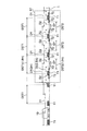
- the figure which shows an example of a structure of the electric vehicle position detection system by 1st Embodiment. 1 is a diagram illustrating an example of a configuration of an electric vehicle 10.
- FIG. 1 is a diagram illustrating an example of the configuration of the electric vehicle position detection system according to the first embodiment.
- the electric vehicle position detection system according to the first embodiment includes a plurality of first tags T1, a plurality of second tags T2, readers 11 and 12 (see FIG. 2), and a database 13 (see FIG. 2). ing.
- the plurality of first tags T1 are tags having the same configuration.
- the plurality of second tags are tags having the same configuration.
- the first tag T1 and the second tag T2 have different configurations.
- the first and second tags T1 and T2 are RFID tags, for example, and may be either active tags or passive tags. However, considering the system cost, installation cost, and the like, the first and second tags T1 and T2 are preferably passive tags that do not require a power source.
- the plurality of first tags T1 are installed along the line 1 and have different identifiers.
- the plurality of second tags T2 are also installed along the line 1 and have different identifiers. That is, each of the plurality of first and second tags T1 and T2 has a unique identifier, and the tag can be specified by reading the identifier.
- Each of the plurality of first tags T1 has a range (hereinafter also referred to as an ID readable range) in which an identifier (hereinafter also referred to as ID) can be read by readers 11 and 12 mounted on the electric vehicle 10 described later.
- the ID readable range of the first tag T1 is the first range D1.
- the first range D1 has an ID readable range of about 2 meters along the line 1.
- the readers 11 and 12 can read the ID of the first tag T1 within a range of about 1 meter before and after the line 1 from the center of the first tag T1.
- the readers 11 and 12 can read the ID of the first tag T1 along the line 1 from about 1 meter before the center of the first tag T1 to about 1 meter ahead of the center of the first tag T1. It is.
- the plurality of second tags T2 also have ID reading ranges.
- the ID readable range of the second tag T2 is the second range D2. Unlike the first range D1, the second range D2 is narrower than the first range D1.
- the second range D ⁇ b> 2 has an ID readable range of about 0.5 meters along the line 1. Therefore, the readers 11 and 12 can read the ID of the second tag T2 within a range of about 0.25 meters before and after the line 1 from the center of the second tag T2. In other words, the readers 11 and 12 set the ID of the second tag T2 from about 0.25 meters before the center of the second tag T2 along the line 1 to about 0.25 meters ahead of the center of the second tag T2. It is possible to read.
- the first and second tags T1 and T2 are arranged along the track 1 in the station where the electric vehicle 10 stops and in the vicinity of the station (hereinafter collectively referred to as the station ST).
- the first tag T1 is arranged at the first installation interval DST1
- the second tag T2 is arranged at the second installation interval DST2. That is, the interval between the centers of the two adjacent first tags T1 is the first installation interval DST1, and the interval between the centers of the two adjacent second tags T2 is the second installation interval DST2.
- the second installation interval DST2 is different from the first installation interval DST1, and is narrower than the first installation interval DST1. Therefore, as shown in FIG. 1, a plurality of second tags T2 can be arranged between two adjacent first tags T1. In the present embodiment, three second tags T2 are disposed between two adjacent first tags T1.
- the first installation interval DST1 is about 1.8 meters
- the second installation interval DST2 is about 0.5 meters.
- the first installation interval DST1 is narrower than the first range D1. Therefore, as shown in FIG. 1, the ID readable range of two adjacent first tags T1 overlaps between the two first tags T1.
- the second installation interval DST2 is substantially equal to the second range D2. Therefore, as shown in FIG. 1, the ID readable range of two adjacent second tags T2 is substantially in contact between the two second tags T2.
- three second tags T2 are arranged with respect to the first tag T1. That is, the ratio of the number of installed first tags T1 and second tags T2 is 1: 3. This ratio is substantially constant along the track 1 at the station ST.
- the second tags T2 may be arranged substantially evenly between the adjacent first tags T1.
- first tag T1 and the second tag T2 may be arranged so as to be shifted from each other in the direction perpendicular to the extending direction of the line 1.
- the second tag T2 can be arranged substantially evenly over the entire line 1 with the installation interval DST2 without considering the installation position of the first tag T1. That is, when viewed from the side of the line 1, the second tag T2 may be installed at a position overlapping the first tag T1.
- the electric vehicle position detection system includes both the first and second tags T1 and T2 at the station ST.
- the electric vehicle 10 not only travels or stops at a low speed at the station ST, but also may pass through the station ST at a high speed.
- the electric vehicle 10 stops at the station ST the electric vehicle 10 travels at a low speed, so that the readers 11 and 12 have relatively low sensitivity (relatively narrow ID readable range) and the ID of the second tag T2.
- the position of the electric vehicle 10 can be accurately detected.
- the readers 11 and 12 provided in the electric car 10 have difficulty in detecting the ID of the second tag T2 having a relatively low sensitivity.
- the station ST includes not only the second tag T2 but also the first tag T1.
- the readers 11 and 12 read the ID of the first tag T1 with relatively high sensitivity (relatively wide ID readable range) to thereby read the electric vehicle 10.
- the electric vehicle position detection system includes both the first and second tags T1 and T2, so that the electric vehicle 10 can be operated at low speed or high speed. The position of the car 10 can be detected.
- the first tag T1 is arranged along the track 1 except for the station and its surroundings, but the second tag T2 is not arranged. This is because the electric vehicle 10 travels at a high speed outside the station and its surroundings, so that it is not necessary to install the low-sensitivity second tag T2.
- the 1st tag T1 is arrange
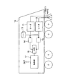
- FIG. 2 is a diagram illustrating an example of the configuration of the electric vehicle 10.
- the electric vehicle 10 includes antennas ANT 1 and ANT 2, readers 11 and 12, a database 13, comparison units 14 and 15, a calculation unit 16, and a control unit 17.
- the two antennas ANT1 and ANT2 are antennas for reading IDs, and are connected to readers 11 and 12, respectively.
- the antennas ANT1 and ANT2 have substantially the same gain characteristics.
- the readers 11 and 12 are configured to acquire the ID from the tag T1 or T2 via the antennas ANT1 and ANT2, respectively.
- the readers 11 and 12 have the same configuration.
- the database 13 stores tag position information indicating the relationship between the IDs of the first and second tags T1 and T2 and the installation positions of the first and second tags T1 and T2.
- the IDs of the first and second tags T1 and T2 are unique for each tag, and correspond to the installation positions of the first and second tags T1 and T2 on a one-to-one basis. Therefore, the position of the electric vehicle 10 can be determined by comparing the ID detected via the antennas ANT1 and ANT2 with the tag position information. Further, the database 13 may further store the tag ID in association with other information such as station number information of the station ST.
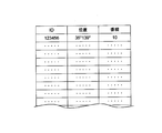
- FIG. 3 is a table showing an example of tag position information.
- the ID of each tag is associated with the position of the tag and the line information of the station ST.
- the ID may be expressed by a numerical value, a character, a symbol, or the like.
- the tag position may be expressed by latitude and longitude.
- the station ST number line may be represented by a numerical value or the like.
- the comparison units 14 and 15 shown in FIG. 2 are connected to the readers 11 and 12, respectively, and are connected to the database 13.
- the comparison unit 14 compares the ID from the reader 11 with the tag position information from the database 13. Thereby, the comparison part 14 collates ID and tag position information, and pinpoints the position of the tag which has the ID.
- the comparison unit 15 compares the ID from the reader 12 with the tag position information from the database 13 separately from the comparison unit 14. Thereby, the comparison part 15 collates ID and tag position information, and pinpoints the position of the tag which has the ID.
- the calculation unit 16 performs a logical operation on the comparison / collation result in the comparison unit 14 and the comparison / collation result in the comparison unit 15.
- the calculation unit 16 is an AND calculation circuit, and calculates a logical product of the comparison / collation results from the comparison units 14 and 15.
- the calculation unit 16 outputs the tag position information (latitude and longitude) to the control unit 17.
- the calculation unit 16 does not output the tag position (latitude, longitude) to the control unit 17 or , Output an error signal.
- the control unit 17 outputs various control signals based on the position information from the calculation unit 16. For example, the control unit 17 outputs a control signal indicating that the electric vehicle 10 is stopped by using the position information from the calculation unit 16 together with the speed information of the electric vehicle 10, brake information (number of notch steps), and the like. Can do. At this time, the electric vehicle 10 may permit the opening of the door of the electric vehicle 10. Alternatively, the opening of the platform door may be permitted on the station ST side. Of course, the control signal from the control unit 17 may be used for other operation control of the electric vehicle 10.
- the plurality of readers 11 and 12 individually read the tag IDs via the antennas ANT1 and ANT2, respectively, and the arithmetic unit 16 calculates the logical product thereof, whereby the tag ID and the tag position reliability are obtained. Can be increased.
- the installation interval DST1 for example, 1.8 m
- the first range D1 for example, 2 meters. Therefore, the ID readable range overlaps between two adjacent first tags T1. Thereby, the reader
- the installation interval DST2 (for example, 0.5 m) of the second tag T2 is equal to the second range D2 (for example, 0.5 meter).
- the second tag T2 is not provided at the installation position of the first tag T1. Therefore, the ID readable range of the two adjacent second tags T2 is set so as to contact between the two adjacent first tags T1.
- the readers 11 and 12 can read the ID of the second tag T2 between the two adjacent first tags T1.
- the readers 11 and 12 can detect where the readers 11 and 12 are located between the two adjacent first tags T1 by reading the ID of the second tag T2.
- the readers 11 and 12 can accurately detect the position of the electric vehicle 10 by the second tag T2 interpolating the space between the first tags T1.
- the readers 11 and 12 perform high-speed operation in areas other than the electric cars passing through the station ST and the station ST.
- the position of the traveling electric vehicle can also be detected.
- the readers 11 and 12 accurately detect the position of the electric vehicle that travels at a high speed in the area other than the station ST and the station ST, and the position of the electric vehicle that travels at a low speed in the station ST. Both can be detected accurately.
- the readers 11 and 12 When the electric vehicle 10 is traveling at high speed, the readers 11 and 12 have the accuracy of the first range D1 (for example, 2 meters), that is, an error of ⁇ D1 ⁇ 1/2 (for example, an error of ⁇ 1 meter). ) Can identify the position of the electric car.
- the readers 11 and 12 when the electric vehicle 10 is traveling at a low speed, the readers 11 and 12 have the accuracy of the second range D2 (for example, 0.5 meters), that is, an error of ⁇ D2 ⁇ 1/2 (for example, ⁇
- the position of the electric car can be specified with an error of 0.25 meters.
- the electric vehicle position detection system according to the present embodiment can accurately detect the position of the electric vehicle regardless of the speed of the electric vehicle. Moreover, since the electric vehicle position detection system according to the present embodiment employs RFID (passive tag or the like), the installation cost can be kept relatively low.
- the readers 11 and 12 can always detect the ID of both or either of the first tag T1 and the second tag T2. Therefore, the electric vehicle position detection system according to the present embodiment can continuously detect the position of the electric vehicle 10 with the accuracy as described above while the vehicle 1 is traveling on the track 1.
- FIG. 4 is a diagram illustrating an example of the configuration of the electric vehicle position detection system according to the second embodiment.
- the installation interval DST2 of the second tag T2 is wider than that of the first embodiment.
- the installation interval DST2 of the second tag T2 is about 1 meter.
- Other configurations of the second embodiment may be the same as the corresponding configurations of the first embodiment.
- the ID readable ranges of the two adjacent second tags T2 are separated from each other as shown in FIG. Accordingly, a space region SP is generated between the adjacent two first tags T1 and between the ID readable ranges of the two adjacent second tags T2.
- the space area SP is a range in which the ID of the second tag T2 cannot be read between two adjacent first tags T1.
- the readers 11 and 12 cannot read the ID of the second tag T2 in the space area SP.
- the electric vehicle position detection system shows that the readers 11 and 12 are in the space region SP.
- the readers 11 and 12 detect the ID of a second tag T2_1 and then do not detect the ID of the second tag T2_2 adjacent to the second tag T2_1, the readers 11 and 12 It turns out that it exists in the space area
- the electric vehicle position detection system performs the same operation with the same accuracy as that of the first embodiment even though there is a space region SP between the ID readable ranges of the adjacent second tags T2.
- the position of the car 10 can be detected. That is, even if the number of installed second tags T2 is reduced as in the second embodiment, the detection accuracy of the position of the electric vehicle 10 can be maintained.
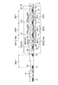
- FIG. 5 is a diagram illustrating an example of the configuration of the electric vehicle position detection system according to the third embodiment.
- the electric vehicle position detection system according to the third embodiment is further provided with a plurality of third tags T3 that are installed along the track 1 in the station ST and have different IDs.
- the third tag T3 is an RFID tag, for example, and may be either an active tag or a passive tag. However, considering the cost of the system, the installation cost, and the like, the third tag T3 is also preferably a passive tag that does not require a power source, like the first and second tags T1 and T2.
- the plurality of third tags T3 are installed along the line 1 and have different identifiers. That is, each of the plurality of third tags T3 has a unique identifier, and the tag can be specified by reading the identifier.
- the third tag T3 has a third range D3 as an ID readable range.
- the third range D3 is a range narrower than the first and second ranges D1 and D2. That is, the third tag T3 is a tag with lower sensitivity than the first and second tags T1 and T2.
- the third tag T3 has an ID readable range of about 0.25 meters along the line 1. Therefore, the readers 11 and 12 can read the ID of the third tag T3 within a range of about 0.125 meters in the front and rear along the line 1 from the center of the third tag T3. In other words, the readers 11 and 12 set the ID of the third tag T3 from about 0.125 meters before the center of the third tag T3 along the line 1 to about 0.125 meters ahead of the center of the third tag T3. It is possible to read.
- the third tag T3 is disposed along the track 1 at the station ST.
- the third tag T3 is arranged at the third installation interval DST3. That is, the interval between the centers of two adjacent third tags T3 is the third installation interval DST3.
- the third installation interval DST3 is narrower than the installation interval DST1 of the first tag T1 and the installation interval DST2 of the second tag T2.
- a plurality of third tags T3 may be disposed between two adjacent second tags T2.
- two third tags T3 are arranged between two adjacent second tags T2.
- the third installation interval DST3 is, for example, about 0.25 meters and the center thereof is set. You may set so that it may correspond to the center of 1st and 2nd installation space
- the third tag T3 may be disposed so as to be shifted from the first and second tags T1 and T2 in the direction perpendicular to the extending direction of the line 1.
- the third tag T3 can be arranged substantially evenly over the entire line 1 with the installation interval DST3 without considering the installation positions of the first and second tags T1 and T2. That is, when viewed from the side of the line 1, the third tag T3 may be installed at a position overlapping the first and second tags T1 and T2.
- the electric vehicle position detection system includes the third tag T3 having the third range narrower than the first and second ranges as the ID readable range.
- the installation interval DST3 of the third tag T3 is narrower than the installation interval DST1 of the first tag T1 and the installation interval DSR2 of the second tag T2.
- the readers 11 and 12 have an accuracy of the third range D3 (for example, 0.25 meter), that is, an error of ⁇ D3 ⁇ 1/2 (for example, ⁇
- the position of the electric car can be specified with an error of 0.125 meters.
- the third embodiment can more accurately detect the position of the electric vehicle traveling at a low speed at the station ST.
- Other configurations of the third embodiment may be the same as the corresponding configurations of the first or second embodiment. Therefore, the third embodiment can also obtain the effects of the first or second embodiment.
- the electric vehicle position detection system may further include a tag (not shown) having a narrower ID readable range than the third range D3. Thereby, the electric vehicle position detection system can detect the position of the electric vehicle 10 with higher accuracy.
- the electric vehicle position detection system may further include a tag having a wider ID readable range than the first range D1. Thereby, in the electric vehicle position detection system, the readers 11 and 12 can read the ID of the tag in the electric vehicle 10 that travels at a higher speed.
- FIG. 6 is a diagram showing an ID readable range.
- the ID readable range described below may be any of the first to third ranges D1 to D3.
- the ID readable range (first range D1) of the first tag T1 will be described.
- the reading power Vread of the readers 11 and 12 is almost a peak with the center of the first tag T1 as a peak, and decreases as the distance from the center of the first tag T1 increases. Assuming that the threshold voltage at which the readers 11 and 12 can read information is Vth, the range in which the readers 11 and 12 can reliably read the ID from the first tag T1 is the first range D1 in which Vread surely exceeds Vth. It becomes.
- the power Vread may exceed the threshold voltage Vth due to reflection or refraction of radio waves.
- the range in which the readers 11 and 12 can reliably read the ID from the first tag T1 is preferably set as the first range D1. Since the first range D1 is related to the speed of the electric vehicle 10, the first range D1 is set in consideration of the speed of the electric vehicle 10.
- the reception voltage Vrcv is surely at a high level. Therefore, the electric vehicle position detection system can reliably receive the reception signal Srcv in the first range D1.
- the first range D1 is set to a range in which the reception signal Srcv can be reliably received.
- the readers 11 and 12 continuously receive the ID of any of the tags T1 to T3 on the line 1. Therefore, the position of the electric vehicle 10 is continuously detected with any accuracy of the tags T1 to T3. As a result, the electric vehicle position detection system can provide highly reliable position information.
Landscapes
- Engineering & Computer Science (AREA)
- Radar, Positioning & Navigation (AREA)
- Remote Sensing (AREA)
- Mechanical Engineering (AREA)
- Computer Networks & Wireless Communication (AREA)
- Physics & Mathematics (AREA)
- General Physics & Mathematics (AREA)
- Power Engineering (AREA)
- Transportation (AREA)
- Radar Systems Or Details Thereof (AREA)
- Electric Propulsion And Braking For Vehicles (AREA)
- Train Traffic Observation, Control, And Security (AREA)
Abstract
本実施形態による電気車位置検知システムは、複数の第1タグと、複数の第2タグと、リーダとを備える。複数の第1タグは、線路に沿って設置され、互いに異なる識別子を有する。複数の第2タグは、線路に沿って設置され、互いに異なる識別子を有する。リーダは、線路上を走行する電気車に搭載され、複数の第1タグの識別子および複数の第2タグの識別子を読み取り可能である。複数の第1タグは、リーダが識別子を読み取ることができる範囲として第1範囲を有する。複数の第2タグは、リーダが識別子を読み取ることができる範囲として第1範囲と異なる第2範囲を有する。複数の第1タグの設置間隔は、複数の第2タグの設置間隔と異なる。
Description
本発明の実施形態は、電気車位置検知システムに関する。
列車が安全に走行および停止するために、自動列車停止装置(ATS(Automatic Train Stop))、自動列車制御装置(ATC(Automatic Train Control))、自動運転装置(ATO(Automatic Train Operation))、定位置停止装置(TASC(Train Automatic Stop-position Controller))、列車制御システム(CBTC(Communication Based Train Control))等の保安装置または運転支援装置が開発されている。これらの保安装置または運転支援装置には、トランスポンダまたは軌道回路のような列車の位置を特定するための装置が必要となる。しかし、トランスポンダや軌道回路は、機器コストおよび設置コストが高いという問題があった。また、列車の位置を特定するためにGPS(Global Positioning System)を用いた場合、GPSの電波の届く範囲が限定され、かつ、位置精度の信頼性に問題がある。
そこで、RFID(Radio Frequency Identifier)を用いることが考えられている。RFIDの信号処理時間を考慮すると、列車が高速走行している場合には、タグのID読取り可能範囲は広い方が好ましい。即ち、タグは高感度であることが好ましい。これにより、列車が高速走行していても、リーダがタグのIDを確実に読み取ることができる。
一方、列車が駅で停止しようとするときに低速走行する場合、列車の位置を正確に検知する必要がある。しかし、タグのID読取り可能範囲が広いと、列車がその広い範囲内のどこに位置するのか不明となってしまう。従って、列車が低速走行している場合には、タグのID読取り可能範囲は狭い方が好ましい。即ち、タグは、低感度であることが好ましい。
このように、RFIDを用いた場合、列車の速度によって、適切なID読取り可能範囲についてトレードオフの関係が生じてしまう。
列車の速度に依らず、列車の位置を正確かつ低コストで検知することができる電気車位置検知システムを提供する。
本実施形態による電気車位置検知システムは、複数の第1タグと、複数の第2タグと、リーダとを備える。複数の第1タグは、線路に沿って設置され、互いに異なる識別子を有する。複数の第2タグは、線路に沿って設置され、互いに異なる識別子を有する。リーダは、線路上を走行する電気車に搭載され、複数の第1タグの識別子および複数の第2タグの識別子を読み取り可能である。複数の第1タグは、リーダが識別子を読み取ることができる範囲として第1範囲を有する。複数の第2タグは、リーダが識別子を読み取ることができる範囲として第1範囲と異なる第2範囲を有する。複数の第1タグの設置間隔は、複数の第2タグの設置間隔と異なる。
以下、図面を参照して本発明に係る実施形態を説明する。本実施形態は、本発明を限定するものではない。
(第1の実施形態)
図1は、第1の実施形態による電気車位置検知システムの構成の一例を示す図である。第1の実施形態による電気車位置検知システムは、複数の第1タグT1と、複数の第2タグT2と、リーダ11、12(図2参照)と、データベース13(図2参照)とを備えている。複数の第1タグT1は、互いに同一の構成を有するタグである。複数の第2タグは、互いに同一の構成を有するタグである。一方、第1タグT1と第2タグT2とは互いに異なる構成を有する。
図1は、第1の実施形態による電気車位置検知システムの構成の一例を示す図である。第1の実施形態による電気車位置検知システムは、複数の第1タグT1と、複数の第2タグT2と、リーダ11、12(図2参照)と、データベース13(図2参照)とを備えている。複数の第1タグT1は、互いに同一の構成を有するタグである。複数の第2タグは、互いに同一の構成を有するタグである。一方、第1タグT1と第2タグT2とは互いに異なる構成を有する。
第1および第2タグT1、T2は、例えば、RFIDのタグであり、アクティブタグまたはパッシブタグのいずれでもよい。ただし、システムのコストおよび設置コスト等を考慮すると、第1および第2タグT1、T2は、電源を必要としないパッシブタグであることが好ましい。
複数の第1タグT1は、線路1に沿って設置され、互いに異なる識別子を有する。複数の第2タグT2も、線路1に沿って設置され、互いに異なる識別子を有する。即ち、複数の第1および第2タグT1、T2は、それぞれ固有の識別子を有しており、その識別子を読み取ることによってタグを特定することができる。
複数の第1タグT1は、それぞれ、後述する電気車10に搭載されたリーダ11、12が識別子(以下、IDともいう)を読み取ることができる範囲(以下、ID読取り可能範囲ともいう)を有する。第1タグT1のID読取り可能範囲は、第1範囲D1である。例えば、第1範囲D1は、線路1に沿って約2メートルのID読取り可能範囲を有する。従って、リーダ11、12は、第1タグT1の中心から線路1に沿って前後約1メートルずつの範囲内で第1タグT1のIDを読み取ることができる。換言すると、リーダ11、12は、線路1に沿って第1タグT1の中心より約1メートル手前から、第1タグT1の中心より約1メートル先まで第1タグT1のIDを読み取ることが可能である。
複数の第2タグT2も、それぞれID読取り可能範囲を有する。第2タグT2のID読取り可能範囲は、第2範囲D2である。第2範囲D2は、第1範囲D1と異なり、第1範囲D1よりも狭い。例えば、第2範囲D2は、線路1に沿って約0.5メートルのID読取り可能範囲を有する。従って、リーダ11、12は、第2タグT2の中心から線路1に沿って前後約0.25メートルずつの範囲内で第2タグT2のIDを読み取ることができる。換言すると、リーダ11、12は、線路1に沿って第2タグT2の中心より約0.25メートル手前から、第2タグT2の中心より約0.25メートル先まで第2タグT2のIDを読み取ることが可能である。
第1および第2タグT1、T2は、電気車10が停車する駅および該駅周辺(以下、まとめて駅STともいう)において、線路1に沿って配置されている。第1タグT1は、第1設置間隔DST1で配置されており、第2タグT2は、第2設置間隔DST2で配置されている。即ち、隣接する2つの第1タグT1の中心間の間隔は第1設置間隔DST1であり、隣接する2つの第2タグT2の中心間の間隔は第2設置間隔DST2となる。
第2設置間隔DST2は、第1設置間隔DST1と異なり、第1設置間隔DST1よりも狭い。従って、図1に示すように、複数の第2タグT2が、隣接する2つの第1タグT1間に配置され得る。本実施形態では、3つの第2タグT2が、隣接する2つの第1タグT1間に配置されている。
例えば、第1設置間隔DST1は、約1.8メートルであり、第2設置間隔DST2は、約0.5メートルである。この場合、第1設置間隔DST1は、第1範囲D1よりも狭い。従って、図1に示すように、隣接する2つの第1タグT1のID読取り可能範囲は、その2つの第1タグT1の間において重複している。また、第2設置間隔DST2は、第2範囲D2とほぼ等しい。従って、図1に示すように、隣接する2つの第2タグT2のID読取り可能範囲は、その2つの第2タグT2の間においてほぼ接している。
本実施形態では、第1タグT1に対して3つの第2タグT2が配置されている。即ち、第1タグT1と第2タグT2との設置個数の比率は1対3である。この比率は、駅STにおいて線路1に沿ってほぼ一定である。例えば、第2タグT2は、隣接する第1タグT1間においてほぼ均等に配置されていてもよい。
さらに、第1タグT1と第2タグT2とは、線路1の延伸方向に対して垂直方向に互いにずれて配置されていてもよい。この場合、第2タグT2は、第1タグT1の設置位置を考慮すること無く、設置間隔DST2で線路1の全体にわたってほぼ均等に配置され得る。即ち、線路1の側方から見たときに、第2タグT2は、第1タグT1と重複した位置に設置されてもよい。
以上のように、本実施形態による電気車位置検知システムは、駅STにおいて、第1および第2タグT1、T2の両方を備えている。ここで、電気車10は、駅STにおいて低速で走行または停止するだけでなく、駅STを高速で通過する場合もある。例えば、駅STにおいて電気車10が停止する場合、電気車10は低速で走行するので、リーダ11、12は、比較的感度の低い(ID読取り可能範囲の比較的狭い)第2タグT2のIDを読み取ることによって、電気車10の位置を正確に検知することができる。一方、電気車が駅STを高速で通過する場合、電気車10に設けられたリーダ11、12は、比較的感度の低い第2タグT2のIDを検知することが困難であり、第2タグT2では電気車の位置を正確に検知することができない。従って、本実施形態による電気車位置検知システムでは、駅STにおいて、第2タグT2だけでなく、第1タグT1も備えている。これにより、電気車10が駅STを高速で通過する場合、リーダ11、12は、比較的感度の高い(ID読取り可能範囲の比較的広い)第1タグT1のIDを読み取ることによって電気車10の位置を正確に検知することができる。このように、駅STにおいて、電気車位置検知システムは、第1および第2タグT1、T2の両方を備えることによって、電気車10が低速で走行しても、高速で走行しても、電気車10の位置を検知することができる。
一方、駅およびその周辺以外において、第1タグT1は、線路1に沿って配置されているものの、第2タグT2は配置されていない。駅およびその周辺以外では、電気車10は高速で走行するため、低感度の第2タグT2の設置は不要であるからである。尚、第1タグT1は、駅STにおける第1タグT1と同様に第1設置間隔DST1ごとに配置されている。
図2は、電気車10の構成の一例を示す図である。電気車10は、アンテナANT1、ANT2と、リーダ11、12と、データベース13と、比較部14、15と、演算部16と、制御部17とを備えている。
2つのアンテナANT1、ANT2は、IDの読み取り用のアンテナであり、それぞれリーダ11、12に接続されている。アンテナANT1、ANT2は、ほぼ同等の利得特性を有する。
リーダ11、12は、それぞれアンテナANT1、ANT2を介してタグT1またはT2からのIDを取得するように構成されている。リーダ11、12は、同じ構成を有する。
データベース13は、第1および第2タグT1、T2のIDと第1および第2タグT1、T2の設置位置と関係を示すタグ位置情報を格納する。第1および第2タグT1、T2のIDは、各タグについて固有のものであり、第1および第2タグT1、T2のそれぞれの設置位置と一対一に対応する。従って、アンテナANT1、ANT2を介して検出されたIDとタグ位置情報とを照合すれば、電気車10の位置が判明する。また、データベース13は、さらにタグIDを駅STの番線情報等の他の情報と関連付けて格納してもよい。
例えば、図3は、タグ位置情報の一例を示すテーブルである。タグ位置情報では、各タグのIDがそのタグの位置および駅STの番線情報と関連付けられている。IDは、数値、文字、記号等で表せばよい。タグの位置は、緯度および経度等で表せばよい。駅STの番線は、数値等で表せばよい。
図2に示す比較部14、15は、それぞれリーダ11、12に接続されており、かつ、データベース13に接続されている。比較部14は、リーダ11からのIDをデータベース13からのタグ位置情報と比較する。これにより、比較部14は、IDとタグ位置情報とを照合し、そのIDを有するタグの位置を特定する。比較部15は、比較部14とは別に、リーダ12からのIDをデータベース13からのタグ位置情報と比較する。これにより、比較部15は、IDとタグ位置情報とを照合し、そのIDを有するタグの位置を特定する。
演算部16は、比較部14での比較・照合結果と、比較部15での比較・照合結果とを論理演算する。例えば、演算部16は、AND演算回路であり、比較部14および15からの比較・照合結果の論理積を演算する。演算部16は、比較部14からの比較・照合結果と比較部15からの比較・照合結果とが一致する場合、制御部17にタグの位置情報(緯度、経度)を出力する。一方、演算部16は、比較部14からの比較・照合結果と比較部15からの比較・照合結果とが一致しない場合、制御部17にタグの位置(緯度、経度)を出力しないか、あるいは、エラー信号を出力する。
制御部17は、演算部16からの位置情報に基づいて様々な制御信号を出力する。例えば、制御部17は、電気車10の速度情報、ブレーキ情報(ノッチ段数)等とともに演算部16からの位置情報を用いて、電気車10が停止していることを示す制御信号を出力することができる。このとき、電気車10は、電気車10の車両のドアの開扉を許可してもよい。あるいは、駅ST側において、ホームドアの開扉を許可してもよい。勿論、制御部17からの制御信号は、電気車10の他の動作制御に用いられてもよい。
このように、複数のリーダ11、12が、それぞれ個別にアンテナANT1、ANT2を介してタグのIDを読み取り、演算部16がその論理積を演算することによって、タグIDおよびタグの位置の信頼性を高めることができる。
次に、図1を再度参照し、第1タグT1および第2タグT2の配置について考察する。図1に示す配置では、第1タグT1の設置間隔DST1(例えば、1.8m)は、第1範囲D1(例えば、2メートル)未満である。従って、ID読取り可能範囲は、隣接する2つの第1タグT1において重複している。これにより、リーダ11、12は、走行中あるいは停車中において、いずれかの第1タグT1のIDを読み取ることができる。
第2タグT2の設置間隔DST2(例えば、0.5m)は、第2範囲D2(例えば、0.5メートル)に等しい。ただし、第2タグT2は、第1タグT1の設置位置には設けられていない。従って、隣接する2つの第2タグT2のID読取り可能範囲は、隣接する2つの第1タグT1間において接するように設定されている。これにより、リーダ11、12は、隣接する2つの第1タグT1間において第2タグT2のIDを読み取ることができる。リーダ11、12は、第2タグT2のIDを読み取ることによって、リーダ11、12が隣接する2つの第1タグT1間のいずれの位置にいるかを検知することができる。このように、第2タグT2が第1タグT1間のスペースを補間することによって、リーダ11、12は、電気車10の位置を正確に検知することができる。
また、第1タグT1は、駅STおよび駅ST以外の領域において第1設置間隔DST1で配置されているため、リーダ11、12は、駅STを通過する電気車や駅ST以外の領域を高速走行する電気車の位置も検知することができる。
このように、本実施形態では、リーダ11、12は、駅STおよび駅ST以外の領域において高速走行する電気車の位置を正確に検知し、並びに、駅STにおいて低速走行する電気車の位置の両方を正確に検知することができる。
電気車10が高速走行している場合には、リーダ11、12は、第1範囲D1(例えば、2メートル)の精度、即ち、±D1×1/2の誤差(例えば、±1メートルの誤差)で電気車の位置を特定することができる。一方、電気車10が低速走行している場合には、リーダ11、12は、第2範囲D2(例えば、0.5メートル)の精度、即ち、±D2×1/2の誤差(例えば、±0.25メートルの誤差)で電気車の位置を特定することができる。
このように、本実施形態による電気車位置検知システムは、電気車の速度に依らず、電気車の位置を正確で検知することができる。また、本実施形態による電気車位置検知システムは、RFID(パッシブタグ等)を採用しているので、設置コストを比較的低く抑えることができる。
リーダ11、12は、第1タグT1または第2タグT2の両方またはいずれか一方のIDを常に検出可能である。従って、本実施形態による電気車位置検知システムは、線路1を走行している期間中、上記のような精度で電気車10の位置を継続的に検知し続けることができる。
(第2の実施形態)
図4は、第2の実施形態による電気車位置検知システムの構成の一例を示す図である。第2の実施形態では、第2タグT2の設置間隔DST2が第1の実施形態のそれよりも広い。例えば、第2タグT2の設置間隔DST2は、約1メートルである。第2の実施形態のその他の構成は、第1の実施形態の対応する構成と同様でよい。
図4は、第2の実施形態による電気車位置検知システムの構成の一例を示す図である。第2の実施形態では、第2タグT2の設置間隔DST2が第1の実施形態のそれよりも広い。例えば、第2タグT2の設置間隔DST2は、約1メートルである。第2の実施形態のその他の構成は、第1の実施形態の対応する構成と同様でよい。
第2タグT2の設置間隔DST2を広く設定することよって、図4に示すように、隣接する2つの第2タグT2のID読み取り可能範囲は互いに離間している。従って、隣接する2つの第1タグT1間において、隣接する2つの第2タグT2のID読み取り可能範囲の間には、スペース領域SPが生じる。スペース領域SPは、隣接する2つの第1タグT1間において、第2タグT2のIDを読み取ることができない範囲である。
リーダ11、12は、スペース領域SPにおいて第2タグT2のIDを読み取ることはできない。しかし、この場合、電気車位置検知システムは、リーダ11、12がスペース領域SPにあることが分かる。例えば、リーダ11、12が或る第2タグT2_1のIDを検知した後、該第2タグT2_1に隣接する第2タグT2_2のIDを検出しなかった場合、リーダ11、12は、その2つの第2タグT2_1とT2_2との間にあるスペース領域SPにあることがわかる。即ち、リーダ11、12は、最後に検出したIDに対応する第2タグT2_1とそれに隣接しまだIDを検出していない第2タグT2_2との間のスペース領域SPにあることが分かる。
従って、第2の実施形態による電気車位置検知システムは、隣接する第2タグT2のID読み取り可能範囲間にスペース領域SPがあるにもかかわらず、第1の実施形態と同程度の精度で電気車10の位置を検知することができる。即ち、第2の実施形態のように第2タグT2の設置個数を低減させても、電気車10の位置の検知精度を維持することができる。
(第3の実施形態)
図5は、第3の実施形態による電気車位置検知システムの構成の一例を示す図である。第3の実施形態による電気車位置検知システムは、駅ST内の線路1に沿って設置され、互いに異なるIDを有する複数の第3タグT3をさらに備えている。
図5は、第3の実施形態による電気車位置検知システムの構成の一例を示す図である。第3の実施形態による電気車位置検知システムは、駅ST内の線路1に沿って設置され、互いに異なるIDを有する複数の第3タグT3をさらに備えている。
第3タグT3は、例えば、RFIDのタグであり、アクティブタグまたはパッシブタグのいずれでもよい。ただし、システムのコストおよび設置コスト等を考慮すると、第3タグT3も、第1および第2タグT1、T2と同様に、電源を必要としないパッシブタグであることが好ましい。
複数の第3タグT3は、線路1に沿って設置され、互いに異なる識別子を有する。即ち、複数の第3タグT3は、それぞれ固有の識別子を有しており、その識別子を読み取ることによってタグを特定することができる。
第3タグT3は、ID読み取り可能範囲として第3範囲D3を有する。第3範囲D3は、第1および第2範囲D1、D2よりも狭い範囲である。即ち、第3タグT3は、第1および第2タグT1、T2よりも低感度のタグである。例えば、第3タグT3は、線路1に沿って約0.25メートルのID読取り可能範囲を有する。従って、リーダ11、12は、第3タグT3の中心から線路1に沿って前後約0.125メートルずつの範囲内で第3タグT3のIDを読み取ることができる。換言すると、リーダ11、12は、線路1に沿って第3タグT3の中心より約0.125メートル手前から、第3タグT3の中心より約0.125メートル先まで第3タグT3のIDを読み取ることが可能である。
第3タグT3は、駅STにおいて、線路1に沿って配置されている。第3タグT3は、第3設置間隔DST3で配置されている。即ち、隣接する2つの第3タグT3の中心間の間隔は第3設置間隔DST3である。第3設置間隔DST3は、第1タグT1の設置間隔DST1および第2タグT2の設置間隔DST2よりも狭い。図5に示すように、複数の第3タグT3が、隣接する2つの第2タグT2間に配置され得る。本実施形態では、2つの第3タグT3が、隣接する2つの第2タグT2間に配置されている。
例えば、第1設置間隔DST1が約1.8メートルであり、第2設置間隔DST2が約0.5メートルである場合、第3設置間隔DST3は、例えば、約0.25メートルとして、その中心を第1および第2設置間隔DST1、DST2の中心にほぼ一致させるように設定してもよい。即ち、第3タグT3は、隣接する第2タグT2間においてほぼ均等に配置させていてもよい。
さらに、第3タグT3は、第1および第2タグT1、T2と、線路1の延伸方向に対して垂直方向に互いにずれて配置されていてもよい。この場合、第3タグT3は、第1および第2タグT1、T2の設置位置を考慮すること無く、設置間隔DST3で線路1の全体にわたってほぼ均等に配置され得る。即ち、線路1の側方から見たときに、第3タグT3は、第1および第2タグT1、T2と重複した位置に設置されてもよい。
このように、第3の実施形態による電気車位置検知システムは、ID読み取り可能範囲として第1および第2範囲よりも狭い第3範囲を有する第3タグT3を備える。第3タグT3の設置間隔DST3は、第1タグT1の設置間隔DST1および第2タグT2の設置間隔DSR2よりも狭い。これにより、電気車10が低速走行している場合に、リーダ11、12は、第3範囲D3(例えば、0.25メートル)の精度、即ち、±D3×1/2の誤差(例えば、±0.125メートルの誤差)で電気車の位置を特定することができる。その結果、第3の実施形態は、駅STにおいて低速走行する電気車の位置を、より正確に検知することができる。第3の実施形態のその他の構成は、第1または第2の実施形態の対応する構成と同様でよい。従って、第3の実施形態は、第1または第2の実施形態の効果も得ることができる。
尚、電気車位置検知システムは、第3範囲D3よりもID読み取り可能範囲の狭いタグ(図示せず)をさらに備えてもよい。これにより、電気車位置検知システムは、電気車10の位置をさらに精度良く検知することができる。あるいは、電気車位置検知システムは、第1範囲D1よりもID読み取り可能範囲の広いタグをさらに備えてもよい。これにより、電気車位置検知システムは、さらに高速で走行する電気車10においてリーダ11、12がタグのIDを読み取ることができる。
次に、ID読み取り可能範囲について説明する。
図6は、ID読み取り可能範囲を示す図である。以下に説明するID読み取り可能範囲は、第1~第3範囲D1~D3のいずれでもよい。以下、第1タグT1のID読み取り可能範囲(第1範囲D1)について説明する。
リーダ11、12の読み取り電力Vreadは、第1タグT1の中心をピークとしてほぼ山なりとなっており、第1タグT1の中心から離れるに従って小さくなっている。リーダ11、12が情報を読み取ることができる閾値電圧をVthとすると、リーダ11、12が確実に第1タグT1からIDを読み取ることができる範囲は、Vreadが確実にVthを超える第1範囲D1となる。
第1範囲D1の範囲外においても電波の反射や屈折によって電力Vreadが閾値電圧Vthを超える場合がある。しかし、リーダ11、12が確実に第1タグT1からIDを読み取ることができる範囲は、第1範囲D1と設定されることが好ましい。尚、第1範囲D1は、電気車10の速度と関連するので、第1範囲D1は電気車10の速度も考慮して設定される。
このように設定された第1範囲D1において、受信電圧Vrcvは、確実にハイレベルとなる。従って、電気車位置検知システムは、第1範囲D1において、受信信号Srcvを確実に受け取ることができる。このように、第1範囲D1は、受信信号Srcvを確実に受け取ることができる範囲に設定される。
以上の実施形態では、リーダ11、12は、線路1においてタグT1~T3のいずれかのIDを継続的に受信している。従って、電気車10の位置は、タグT1~T3のいずれか精度で継続的に検知している。その結果、電気車位置検知システムは、信頼性の高い位置情報を提供することができる。
本発明のいくつかの実施形態を説明したが、これらの実施形態は、例として提示したものであり、発明の範囲を限定することは意図していない。これら実施形態は、その他の様々な形態で実施されることが可能であり、発明の要旨を逸脱しない範囲で、種々の省略、置き換え、変更を行うことができる。これら実施形態やその変形は、発明の範囲や要旨に含まれると同様に、特許請求の範囲に記載された発明とその均等の範囲に含まれるものである。
Claims (12)
- 線路に沿って設置され、互いに異なる識別子を有する複数の第1タグと、
前記線路に沿って設置され、互いに異なる識別子を有する複数の第2タグと、
前記線路上を走行する電気車に搭載され、前記複数の第1タグの識別子および前記複数の第2タグの識別子を読み取り可能なリーダとを備え、
前記複数の第1タグは、前記リーダが識別子を読み取ることができる範囲として第1範囲を有し、
前記複数の第2タグは、前記リーダが識別子を読み取ることができる範囲として前記第1範囲と異なる第2範囲を有し、
前記複数の第1タグの設置間隔は、前記複数の第2タグの設置間隔と異なる、電気車位置検知システム。 - 前記第2範囲は、前記第1範囲よりも狭く、
前記複数の第2タグの設置間隔は、前記複数の第1タグの設置間隔よりも狭い、請求項1に記載の電気車位置検知システム。 - 前記第1タグと前記第2タグとの設置個数の比率は前記線路に沿ってほぼ一定である、請求項1に記載の電気車位置検知システム。
- 前記電気車が停車する駅および該駅周辺において、前記第1タグおよび前記第2タグの両方が前記線路に沿って配置されており、
前記駅および該駅周辺以外において、前記第1タグが前記線路に沿って配置されているが、前記第2タグは配置されていない、請求項1に記載の電気車位置検知システム。 - 前記電気車が停車する駅および該駅周辺において、前記第1タグおよび前記第2タグの両方が前記線路に沿って配置されており、
前記駅および該駅周辺以外において、前記第1タグが前記線路に沿って配置されているが、前記第2タグは配置されていない、請求項2に記載の電気車位置検知システム。 - 前記第1タグの設置間隔は、前記第1範囲より狭く、
前記第2タグの設置間隔は、前記第2範囲以上である、請求項1に記載の電気車位置検知システム。 - 前記第1タグの設置間隔は、前記第1範囲より狭く、
前記第2タグの設置間隔は、前記第2範囲以上である、請求項2に記載の電気車位置検知システム。 - 前記リーダが、前記第2タグT2_1を検知した後に、該第2タグT2_1に対して前記電気車の進行方向に隣接する前記第2タグT2_2を検知していない場合、前記リーダは、前記第2タグT2_1と前記第2タグT2_2との間のスペース領域上にあると判断する、請求項6に記載の電気車位置検知システム。
- 前記リーダが、前記第2タグT2_1を検知した後に、該第2タグT2_1に対して前記電気車の進行方向に隣接する前記第2タグT2_2を検知していない場合、前記リーダは、前記第2タグT2_1と前記第2タグT2_2との間のスペース領域上にあると判断する、請求項7に記載の電気車位置検知システム。
- 前記第1および第2タグの識別子と前記第1および第2タグの設置位置と関係を示すタグ位置情報を格納する記憶部をさらに備えた請求項1に記載の電気車位置検知システム。
- 前記線路に沿って設置され、互いに異なる識別子を有する複数の第3タグをさらに備え、
前記複数の第3タグは、前記リーダが識別子を読み取ることができる範囲として前記第1および第2範囲よりも狭い第3範囲を有し
前記複数の第3タグの設置間隔は、前記複数の第1タグの設置間隔および前記複数の第2タグの設置間隔よりも狭い、請求項1に記載の電気車位置検知システム。 - 前記第1~第3タグの設置個数の比率は前記線路に沿ってほぼ一定である、請求項11に記載の電気車位置検知システム。
Priority Applications (2)
| Application Number | Priority Date | Filing Date | Title |
|---|---|---|---|
| SG11201709284QA SG11201709284QA (en) | 2015-05-13 | 2016-04-18 | Electric vehicle position detection system |
| CN201680027168.9A CN107709135B (zh) | 2015-05-13 | 2016-04-18 | 电动车位置检测系统 |
Applications Claiming Priority (2)
| Application Number | Priority Date | Filing Date | Title |
|---|---|---|---|
| JP2015098396A JP6491948B2 (ja) | 2015-05-13 | 2015-05-13 | 電気車位置検知システム |
| JP2015-098396 | 2015-05-13 |
Publications (1)
| Publication Number | Publication Date |
|---|---|
| WO2016181763A1 true WO2016181763A1 (ja) | 2016-11-17 |
Family
ID=57247914
Family Applications (1)
| Application Number | Title | Priority Date | Filing Date |
|---|---|---|---|
| PCT/JP2016/062258 Ceased WO2016181763A1 (ja) | 2015-05-13 | 2016-04-18 | 電気車位置検知システム |
Country Status (4)
| Country | Link |
|---|---|
| JP (1) | JP6491948B2 (ja) |
| CN (1) | CN107709135B (ja) |
| SG (1) | SG11201709284QA (ja) |
| WO (1) | WO2016181763A1 (ja) |
Cited By (2)
| Publication number | Priority date | Publication date | Assignee | Title |
|---|---|---|---|---|
| CN107526090A (zh) * | 2017-06-19 | 2017-12-29 | 阿里巴巴集团控股有限公司 | 位置定位方法、设备及系统、计算机可读存储介质 |
| CN109050584A (zh) * | 2018-08-17 | 2018-12-21 | 成都市新筑路桥机械股份有限公司 | 一种基于无线应答的轨道车辆测速方法 |
Families Citing this family (1)
| Publication number | Priority date | Publication date | Assignee | Title |
|---|---|---|---|---|
| CN113792562B (zh) * | 2021-09-16 | 2024-06-14 | 华南农业大学 | 一种电动单轨运送装备的高频rfid定位阅读器 |
Citations (4)
| Publication number | Priority date | Publication date | Assignee | Title |
|---|---|---|---|---|
| JPS4851185A (ja) * | 1971-10-28 | 1973-07-18 | ||
| JP2012066756A (ja) * | 2010-09-27 | 2012-04-05 | Railway Technical Research Institute | 在線位置検出方法、ブレーキ制御方法、進路制御方法、車上装置及び管理装置 |
| JP2012240660A (ja) * | 2011-05-24 | 2012-12-10 | Toho Electrical Construction Co Ltd | 鉄道車両速度測定装置 |
| JP2013136261A (ja) * | 2011-12-28 | 2013-07-11 | Hitachi Ltd | 鉄道信号システム |
Family Cites Families (8)
| Publication number | Priority date | Publication date | Assignee | Title |
|---|---|---|---|---|
| KR100965894B1 (ko) * | 2008-09-29 | 2010-06-24 | 샬롬엔지니어링 주식회사 | Ats 지상자를 이용한 atp 속도제한 커브 추종 시스템및 방법 |
| CN101770009B (zh) * | 2009-01-06 | 2014-05-21 | 成都西谷曙光数字技术有限公司 | 一种精确射频定位系统 |
| KR20100083051A (ko) * | 2009-01-12 | 2010-07-21 | 김동섭 | 알에프아이디를 이용한 열차 운행 제어 시스템 및 그 제어 방법 |
| KR20100083067A (ko) * | 2009-01-12 | 2010-07-21 | 김동섭 | 무선통신 및 알에프아이디를 이용한 모노레일 차량 운행 제어 시스템 및 그 제어방법 |
| CN202022221U (zh) * | 2011-04-08 | 2011-11-02 | 南京工程学院 | Rfid辅助的地铁列车位置检测及精确停车系统 |
| KR101434165B1 (ko) * | 2012-02-20 | 2014-08-26 | 김재철 | 열차의 역사 승강장 무단 통과 방지장치 |
| CN102680730A (zh) * | 2012-05-23 | 2012-09-19 | 江苏松森信息科技有限公司 | 一种基于rfid的轨道车辆测速系统及方法 |
| KR101374350B1 (ko) * | 2012-12-04 | 2014-03-19 | 한국철도기술연구원 | 열차 위치 검출 장치 |
-
2015
- 2015-05-13 JP JP2015098396A patent/JP6491948B2/ja active Active
-
2016
- 2016-04-18 CN CN201680027168.9A patent/CN107709135B/zh active Active
- 2016-04-18 WO PCT/JP2016/062258 patent/WO2016181763A1/ja not_active Ceased
- 2016-04-18 SG SG11201709284QA patent/SG11201709284QA/en unknown
Patent Citations (4)
| Publication number | Priority date | Publication date | Assignee | Title |
|---|---|---|---|---|
| JPS4851185A (ja) * | 1971-10-28 | 1973-07-18 | ||
| JP2012066756A (ja) * | 2010-09-27 | 2012-04-05 | Railway Technical Research Institute | 在線位置検出方法、ブレーキ制御方法、進路制御方法、車上装置及び管理装置 |
| JP2012240660A (ja) * | 2011-05-24 | 2012-12-10 | Toho Electrical Construction Co Ltd | 鉄道車両速度測定装置 |
| JP2013136261A (ja) * | 2011-12-28 | 2013-07-11 | Hitachi Ltd | 鉄道信号システム |
Cited By (5)
| Publication number | Priority date | Publication date | Assignee | Title |
|---|---|---|---|---|
| CN107526090A (zh) * | 2017-06-19 | 2017-12-29 | 阿里巴巴集团控股有限公司 | 位置定位方法、设备及系统、计算机可读存储介质 |
| US10952030B2 (en) | 2017-06-19 | 2021-03-16 | Advanced New Technologies Co., Ltd. | Methods, devices, systems, and computer-readable storage mediums for location positioning |
| US11096015B2 (en) | 2017-06-19 | 2021-08-17 | Advanced New Technologies Co., Ltd. | Methods, devices, systems, and computer-readable storage mediums for location positioning |
| CN109050584A (zh) * | 2018-08-17 | 2018-12-21 | 成都市新筑路桥机械股份有限公司 | 一种基于无线应答的轨道车辆测速方法 |
| CN109050584B (zh) * | 2018-08-17 | 2020-09-15 | 成都市新筑路桥机械股份有限公司 | 一种基于无线应答的轨道车辆测速方法 |
Also Published As
| Publication number | Publication date |
|---|---|
| JP6491948B2 (ja) | 2019-03-27 |
| JP2016210381A (ja) | 2016-12-15 |
| CN107709135A (zh) | 2018-02-16 |
| SG11201709284QA (en) | 2017-12-28 |
| CN107709135B (zh) | 2020-09-08 |
Similar Documents
| Publication | Publication Date | Title |
|---|---|---|
| US9499185B2 (en) | Wayside guideway vehicle detection and switch deadlocking system with a multimodal guideway vehicle sensor | |
| EP3950462B1 (en) | Guideway mounted vehicle localization and alignment system and method | |
| EP1396412A1 (en) | Vehicle detection system, in particular for trains | |
| KR20130001652A (ko) | 무선열차검지유닛을 이용한 열차위치 검지 시스템 | |
| CN108263447A (zh) | 列车的定位方法、系统以及列车的联锁装置 | |
| JP6491948B2 (ja) | 電気車位置検知システム | |
| US10101432B2 (en) | System and method for position and proximity detection | |
| KR100985780B1 (ko) | 열차의 접근 경보 장치 및 방법 | |
| US10447349B2 (en) | Wireless communication system and wireless communication apparatus | |
| US8400327B2 (en) | Method for querying a measurement value | |
| JP6584049B2 (ja) | 列車制御装置 | |
| JPH0532166A (ja) | 列車位置検出装置 | |
| US8248209B2 (en) | Device for communicating between a mobile element and a fixed element | |
| JP6962340B2 (ja) | 電子閉塞システム及び指令端末 | |
| JP4845925B2 (ja) | 情報伝送装置 | |
| US11180169B2 (en) | Onboard system, ground system, and information transmission system | |
| KR102522841B1 (ko) | Rfid를 이용한 이중화 열차검지 시스템 | |
| CN109941317B (zh) | 跟踪没有里程表的装有无线电设备的车辆的方法 | |
| JP2022147475A (ja) | 列車識別システム | |
| KR20180029705A (ko) | 비콘을 이용한 주차 차량 감지 장치 및 방법 | |
| JP2022147476A (ja) | 列車識別システム | |
| HK40058706B (en) | Guideway mounted vehicle localization and alignment system and method | |
| KR20130130917A (ko) | 열차위치 검지 시스템 | |
| HK40004359B (en) | Procedure for tracking radio equipped vehicles without odometer | |
| HK40004359A (en) | Procedure for tracking radio equipped vehicles without odometer |
Legal Events
| Date | Code | Title | Description |
|---|---|---|---|
| 121 | Ep: the epo has been informed by wipo that ep was designated in this application |
Ref document number: 16792488 Country of ref document: EP Kind code of ref document: A1 |
|
| WWE | Wipo information: entry into national phase |
Ref document number: 11201709284Q Country of ref document: SG |
|
| NENP | Non-entry into the national phase |
Ref country code: DE |
|
| 122 | Ep: pct application non-entry in european phase |
Ref document number: 16792488 Country of ref document: EP Kind code of ref document: A1 |