WO2016181731A1 - 転倒検知装置および転倒検知方法ならびに被監視者監視装置 - Google Patents
転倒検知装置および転倒検知方法ならびに被監視者監視装置 Download PDFInfo
- Publication number
- WO2016181731A1 WO2016181731A1 PCT/JP2016/061355 JP2016061355W WO2016181731A1 WO 2016181731 A1 WO2016181731 A1 WO 2016181731A1 JP 2016061355 W JP2016061355 W JP 2016061355W WO 2016181731 A1 WO2016181731 A1 WO 2016181731A1
- Authority
- WO
- WIPO (PCT)
- Prior art keywords
- head
- monitored person
- unit
- fall
- image
- Prior art date
Links
Images


Classifications
-
- G—PHYSICS
- G06—COMPUTING; CALCULATING OR COUNTING
- G06T—IMAGE DATA PROCESSING OR GENERATION, IN GENERAL
- G06T7/00—Image analysis
- G06T7/20—Analysis of motion
-
- G—PHYSICS
- G08—SIGNALLING
- G08B—SIGNALLING OR CALLING SYSTEMS; ORDER TELEGRAPHS; ALARM SYSTEMS
- G08B21/00—Alarms responsive to a single specified undesired or abnormal condition and not otherwise provided for
- G08B21/02—Alarms for ensuring the safety of persons
-
- G—PHYSICS
- G08—SIGNALLING
- G08B—SIGNALLING OR CALLING SYSTEMS; ORDER TELEGRAPHS; ALARM SYSTEMS
- G08B25/00—Alarm systems in which the location of the alarm condition is signalled to a central station, e.g. fire or police telegraphic systems
-
- H—ELECTRICITY
- H04—ELECTRIC COMMUNICATION TECHNIQUE
- H04N—PICTORIAL COMMUNICATION, e.g. TELEVISION
- H04N7/00—Television systems
- H04N7/18—Closed-circuit television [CCTV] systems, i.e. systems in which the video signal is not broadcast
Definitions
- the present invention relates to a fall detection device and a fall detection method for detecting a fall of a monitored person to be monitored. And this invention relates to the to-be-monitored person monitoring apparatus using this fall detection apparatus.
- Japan is an aging society, more specifically the ratio of population over 65 years old to the total population due to the improvement of living standards accompanying the post-war high economic growth, improvement of sanitary environment and improvement of medical standards, etc. It is a super-aging society with an aging rate exceeding 21%.
- the total population was about 126.5 million, while the elderly population over the age of 65 was about 25.56 million.
- the total population was about 124.11 million.
- the elderly population will be about 34.56 million.
- nurses who need nursing or nursing care due to illness, injury, elderly age, etc., or those who need nursing care are those who need nursing in a normal society that is not an aging society.
- the fall detection device disclosed in Patent Document 1 includes a camera, an image processing unit that captures a video signal output from the camera, performs difference processing on the captured image, and a difference area obtained by the difference processing. And a judging means for detecting a falling motion of the human body based on the area. More specifically, the determination means determines whether or not a fall has occurred based on an area change per unit time in the human body.
- the fall detection device disclosed in Patent Document 1 detects the fall by the area change per unit time in the human body region. Since the size of the region of the head that appears in the image changes depending on whether or not there is a fall, a method of detecting a fall based on the size of the head region can be considered.
- the present invention has been made in view of the above circumstances, and its object is to provide a fall detection device and a fall detection method that can detect the fall of the monitored person more accurately based on an image obtained by imaging the monitored person from above.
- the present invention also provides a monitored person monitoring device using the fall detection device.
- the fall detection device, the fall detection method, and the monitored person monitoring apparatus In the fall detection device, the fall detection method, and the monitored person monitoring apparatus according to the present invention, an image obtained by capturing the monitored person as the monitoring target from above the monitored person is acquired, and the head candidate is obtained from the image. The head candidate area is extracted, and each time change in each of a plurality of preset parameters related to the head is obtained for the head candidate area, and based on each time change in each of the plurality of parameters A fall in the monitored person is detected. Therefore, the fall detection device, the fall detection method, and the monitored person monitoring apparatus according to the present invention can detect the fall of the monitored person with higher accuracy based on an image obtained by imaging the monitored person from above.
- the monitored person monitoring apparatus includes a behavior detection unit that detects a predetermined behavior set in advance in a monitored person to be monitored, and a notification unit that notifies the predetermined behavior detected by the behavior detection unit to the outside.
- a monitored person monitoring apparatus may be realized by being integrally configured as one device, and may be realized by a plurality of devices as a system.
- the behavior detection unit may be mounted on any of the plurality of devices.
- the first and second embodiments of the monitored person monitoring apparatus will be described in the case where the monitored person monitoring apparatus is realized by a plurality of devices as a system.
- the monitored person monitoring apparatus includes an image acquisition unit that acquires an image of a monitored person that is a monitoring target from above the monitored person, and an image acquired by the image acquisition unit.
- a head candidate extraction unit that extracts a head candidate region that is a candidate for each part, and each time in each of a plurality of preset parameters related to the head with respect to the head candidate region extracted by the head candidate extraction unit
- a parameter calculation unit for obtaining a change, and a fall detection unit for detecting a fall in the monitored person based on each time change in each of the plurality of parameters obtained by the parameter calculation unit, and at least one of the parameters Is extracted from the image acquired by the image acquisition unit.
- the monitored person monitoring apparatus further includes a distance measuring unit that measures the distance to the head of the monitored person from above the monitored person, and the parameter calculation unit includes the image acquisition unit.
- a size calculation unit that obtains, as the parameter, the size of the head of the monitored person as viewed from above, the fall detection unit is configured to include the head calculated by the size calculation unit. The fall of the monitored person is detected based on the time change rate of the difference between the size of the part and the distance to the head measured by the distance measuring unit. Note that, even when the monitored person monitoring apparatus is configured integrally as a single device, the monitored person monitoring apparatus can be configured similarly to the following description.
- the behavior detection unit is mounted on sensor devices SUa and SUb described later together with the notification unit
- other devices in this system for example, a management server device described later
- the monitored person monitoring device can be configured in the same manner as described below.
- the head In the above-described method of detecting a fall by the size of the head region, the head is captured in a substantially circular shape in the image captured from above, and thus a circular region is detected as the head region from the image.
- a substantially circular object that is not the head such as a pillow, a washbasin, a ball, a trash can, and a futon handle is also reflected, so the area of these objects is erroneously detected as the head area, A fall may be erroneously detected.
- the erroneous detection can be avoided by removing the area of these objects at the fixed position from the area for detecting the head in advance.
- these objects do not always exist at a fixed position.
- the first embodiment addresses such a case.
- FIG. 1 is a diagram illustrating a configuration of a monitored person monitoring system according to the embodiment.
- FIG. 2 is a diagram illustrating a configuration of a sensor device in the monitored person monitoring system according to the first embodiment.
- the monitored person monitoring system MSa in the first embodiment of the example in which the monitored person monitoring apparatus is realized as a system is a monitored person (a watching target person) that is a monitoring target (a watching target) to be monitored (a watching target).
- a predetermined action set in Ob (Ob-1 to Ob-4) is detected to monitor the monitored person Ob. For example, as shown in FIG.
- a network such as a LAN (Local Area Network), a telephone network, and a data communication network.
- NW network, communication line
- the network NW may be provided with relays such as repeaters, bridges, routers, and cross-connects that relay communication signals.
- the plurality of sensor devices SUa-1 to SUa-4, the management server device SV, the fixed terminal device SP, and the plurality of portable terminal devices TA-1 and TA-2 are wireless including an access point AP.
- a LAN for example, a LAN according to the IEEE 802.11 standard
- NW is connected to be communicable with each other.
- the monitored person monitoring system MSa is arranged at an appropriate place according to the monitored person Ob.
- the monitored person (person to be watched) Ob is, for example, a person who needs nursing due to illness or injury, a person who needs care due to a decrease in physical ability, a single person living alone, or the like.
- the monitored person Ob may be a person who needs the detection when a predetermined inconvenient event such as an abnormal state occurs in the person. preferable.
- the monitored person monitoring system MSa is suitably arranged in a building such as a hospital, an elderly welfare facility, or a dwelling unit according to the type of the monitored person Ob.
- the monitored person monitoring system MSa is disposed in a building of a care facility that includes a plurality of rooms RM in which a plurality of monitored persons Ob and a plurality of rooms such as a nurse station.
- the sensor device SUa is a device that has a communication function for communicating with other devices SV, SP, and TA via the network NW, detects the monitored person Ob, and transmits the detection result to the management server device SV.
- the sensor device SUa includes a sensor unit 1, a sound input / output unit 2, a control processing unit 3a, a communication interface unit (communication IF unit) 4, and a storage unit 5a. Is provided.
- the sensor unit 1 is a device that is connected to the control processing unit 3a and detects predetermined various amounts set in advance in the monitored person Ob in accordance with the control of the control processing unit 3a.
- the predetermined amounts are appropriately determined according to a predetermined action to be detected in the monitored person Ob.
- the predetermined amounts include the distance to the head of the monitored person Ob.
- the predetermined actions are awakening, getting out of bed, falling, and abnormal movement of the subject Ob, and in order to detect these, the sensor unit 1 includes, for example, a Doppler sensor 11, And a camera 12.
- the Doppler sensor 11 is a body motion sensor that transmits a transmission wave, receives a reflection wave of the transmission wave reflected by an object, and outputs a Doppler frequency component Doppler signal based on the transmission wave and the reflection wave. .
- the frequency of the reflected wave shifts in proportion to the moving speed of the object due to the so-called Doppler effect, so there is a difference (Doppler frequency component) between the frequency of the transmitted wave and the frequency of the reflected wave.
- Doppler sensor 11 generates a signal of the Doppler frequency component as a Doppler signal and outputs it to the control processing unit 3a.
- the transmission wave may be an ultrasonic wave, a microwave, or the like, but is a microwave in the present embodiment. Since the microwave can be transmitted through the clothing and reflected from the body surface of the monitored person Ob, the movement of the body surface can be detected even when the monitored person Ob is wearing clothes.
- the camera 12 is an apparatus that is connected to the control processing unit 3a and generates an image (image data) under the control of the control processing unit 3a.
- the camera 12 is arranged so as to be able to monitor a space (location space, in the example shown in FIG. 1, where the monitored person Ob that is a monitoring target to be monitored) is located. Is captured from above, an image (image data) overlooking the imaging target is generated, and the image of the imaging target is output to the control processing unit 3a.
- the camera 12 is expected to be located at the head of the monitored person Ob in the bedding on which the monitored person Ob is lying (for example, a bed).
- the sensor device SUa uses the camera 12 of the sensor unit 1 to acquire an image of the monitored person Ob taken from above the monitored person Ob, preferably an image taken from directly above the planned head position.
- the camera 12 is an example of an image acquisition unit.
- Such a camera 12 may be a device that generates an image of visible light, but in this embodiment, it is a device that generates an infrared image so that the monitored person Ob can be monitored even in a relatively dark place.
- a camera 12 is, for example, in this embodiment, an imaging optical system that forms an infrared optical image of an imaging target on a predetermined imaging surface, and a light receiving surface that is aligned with the imaging surface.
- An image sensor that converts an infrared optical image in the imaging target into an electrical signal, and image data that is data representing an infrared image in the imaging target by performing image processing on the output of the image sensor.
- the imaging optical system of the camera 12 is preferably a wide-angle optical system (so-called wide-angle lens (including a fisheye lens)) having an angle of view that can capture the entire room RM in which the camera 12 is disposed.
- the sound input / output unit 2 is connected to the control processing unit 3a and is a circuit for acquiring an external sound and inputting it to the sensor device SUa.
- the sound input / output unit 2 corresponds to an electrical signal representing the sound according to the control of the control processing unit 3a. It is a circuit for generating and outputting sound.
- the sound input / output unit 2 includes, for example, a microphone that converts sound acoustic vibrations into electrical signals, and a speaker that converts sound electrical signals into sound acoustic vibrations.
- the sound input / output unit 2 outputs an electric signal representing an external sound to the control processing unit 3a, and converts the electric signal input from the control processing unit 3a into an acoustic vibration of sound and outputs the sound.
- the communication IF unit 4 is a communication circuit that is connected to the control processing unit 3a and performs communication according to the control of the control processing unit 3a.
- the communication IF unit 4 generates a communication signal containing the data to be transferred input from the control processing unit 3a according to the communication protocol used in the network NW of the monitored person monitoring system MSa, and generates the generated communication signal. It transmits to other devices SV, SP, TA via the network NW.
- the communication IF unit 4 receives a communication signal from another device SV, SP, TA via the network NW, extracts data from the received communication signal, and can be processed by the control processing unit 3a. And output to the control processing unit 3a.
- the communication IF unit 4 further uses, for example, standards such as the Bluetooth (registered trademark) standard, the IrDA (Infrared Data Association) standard, and the USB (Universal Serial Bus) standard to input / output data to / from an external device.
- standards such as the Bluetooth (registered trademark) standard, the IrDA (Infrared Data Association) standard, and the USB (Universal Serial Bus) standard to input / output data to / from an external device.
- An interface circuit may be provided.
- the storage unit 5a is a circuit that is connected to the control processing unit 3a and stores various predetermined programs and various predetermined data under the control of the control processing unit 3a.
- the various predetermined programs include, for example, control processing programs such as a monitoring processing program for executing information processing related to monitoring of the monitored person Ob.
- the monitoring processing program includes a behavior detection program for detecting a predetermined behavior in the monitored person Ob based on an output of the sensor unit 1, a notification processing program for notifying the predetermined behavior detected by the behavior detection program to the outside, By using the streaming processing program for streaming the moving image captured by the camera 12 to the fixed terminal device SP or the portable terminal device TA that requested the moving image, and the sound input / output unit 2 or the like, the fixed terminal device SP or the portable terminal A nurse call processing program for making a voice call with the device TA is included.
- the behavior detection program includes a head candidate extraction program for extracting a head candidate region that is a head candidate from an image acquired by the camera 12, and a head candidate region extracted by the head candidate extraction program.
- the parameter calculation program for obtaining each time change in each of a plurality of preset parameters related to the head, and the person to be monitored Ob based on each time change in each of the plurality of parameters obtained by the parameter calculation program A fall detection program for detecting fall is included.
- the various types of predetermined data include data necessary for executing these programs, data necessary for monitoring the monitored person Ob, and the like.
- the storage unit 5a includes, for example, a ROM (Read Only Memory) that is a nonvolatile storage element, an EEPROM (Electrically Erasable Programmable Read Only Memory) that is a rewritable nonvolatile storage element, and the like.
- the storage unit 5a includes a RAM (Random Access Memory) that serves as a working memory of the so-called control processing unit 3a that stores data generated during execution of the predetermined program.
- the control processing unit 3a is a circuit for controlling each unit of the sensor device SUa according to the function of each unit and detecting predetermined amounts set in advance in the monitored person Ob.
- the control processing unit 3a includes, for example, a CPU (Central Processing Unit) and its peripheral circuits.
- the control processing unit 3a functionally includes a control unit 31, a behavior detection processing unit 32, a notification processing unit 33, a streaming processing unit 34, and a nurse call processing unit 35 by executing the control processing program.
- the processing unit 32 functionally includes a moving object extraction unit 321, a head candidate extraction unit 322a, a parameter calculation unit 323a, and a fall detection unit 324a.
- the control unit 31 controls each part of the sensor device SUa according to the function of each part, and controls the entire sensor device SUa.
- the behavior detection processing unit 32 detects a predetermined behavior set in advance in the monitored person Ob based on the output of the sensor unit 1.
- the predetermined behavior is wakeup, getting out of bed, falling, and abnormal movement of the monitored person Ob
- the behavior detection processing unit 32 is based on the output of the sensor unit 1.
- Wake-up, getting-off, falling, and minute body movement abnormality in the monitoring person Ob are detected as detection results, and the detection results are notified to the notification processing unit 33.
- the behavior detection processing unit 32 detects wake-up, getting-off and abnormal body movement of the monitored person Ob based on the output of the sensor unit 1 by a known technique.
- the behavior detection processing unit 32 extracts a moving body region from the image acquired by the camera 12 of the sensor unit 1 as the human body region of the monitored person Ob, and the posture of the monitored person Ob from the aspect ratio of the extracted moving body area ( For example, standing position, sitting position, lying down, etc.) are detected, the position of the detected moving body region is detected, and the distinction between the rising and leaving is determined based on these determinations and the detected posture and position of the monitored person Ob.
- the behavior detection processing unit 32 detects body movement of the chest (vertical movement of the chest) accompanying the breathing motion of the monitored person Ob by the Doppler sensor 11 of the sensor unit 1, and the period disturbance in the body movement of the chest When the amplitude in the body motion of the chest that is equal to or less than a preset threshold is detected, it is determined that the minute motion abnormality is present.
- the behavior detection processing unit 32 functionally includes a moving object extraction unit 321, a head candidate extraction unit 322a, a parameter calculation unit 323a, and a fall detection unit 324a.
- the fall of the monitored person Ob is detected.
- the moving object extraction unit 321 extracts a moving object region from the image acquired by the camera 12 of the sensor unit 1 as a human body region of the monitored person Ob by using a method such as a background difference method or an inter-frame difference method.
- the moving object extraction unit 321 is also used when extracting a moving object in order to detect the above-described wake-up and getting-off, and is shared by these processes.
- a background image is obtained in advance and stored in advance in the storage unit 5a as one of the various predetermined data, and the presence or absence of moving objects is determined from the difference image between the image generated by the camera 12 and the background image. If there is a moving object as a result of this determination, the area of the moving object is set as a moving object area.
- the presence / absence of a moving object is determined from a difference image between an image of a current frame and an image of a past frame (for example, the previous frame) generated by the camera 12. If there is a moving object region, this moving object region is set as the moving object region.
- the moving object extraction unit 321 notifies the head candidate extraction unit 322a of the extracted moving object region.
- the head candidate extraction unit 322a extracts a head candidate region that is a head candidate from the moving object region extracted by the moving object extraction unit 321. In the image picked up from above, the head appears in a substantially circular shape, so a circular region is extracted as the head candidate region from the body movement region. For example, the head candidate extraction unit 322a extracts a circular area from the body movement area as the head candidate area by using a Hough transform that extracts a circular shape. Further, for example, a head shape pattern is prepared in advance and stored in advance in the storage unit 5a as one of the various predetermined data, and the head candidate extraction unit 322a is stored in the storage unit 5a in advance. The shape pattern is searched from the body movement region by using pattern matching, and a region matching the shape pattern of the head is extracted as the head candidate region. The head candidate extraction unit 322a notifies the parameter calculation unit 323a of the extracted head candidate region.
- the parameter calculation unit 323a obtains each time change in each of a plurality of preset parameters related to the head with respect to the head candidate region extracted by the head candidate extraction unit 322a. At least one of the plurality of parameters is extracted from the image acquisition unit that acquires an image captured from above the monitored person, which is an image acquired by the camera 12 in this embodiment.
- the plurality of parameters are, for example, an area of the head candidate region and preset subparameters related to the shape of the head candidate region.
- the sub-parameter is one or more of a circularity of the head candidate region, an aspect ratio of the head candidate region, a skin area ratio of the head candidate region, and a hair area ratio of the head candidate region. is there.
- the circularity is a degree representing how close to a perfect circle.
- the aspect ratio is the ratio of the first length along the first direction and the second length along the second direction orthogonal to the first direction.
- the skin area ratio is a ratio between the total area of the head candidate area and the area of the skin area (skin area) in the head candidate area.
- the hair area ratio is a ratio between the total area of the head candidate area and the area of the hair area (hair area) in the head candidate area.
- the parameter calculation unit 323a performs the time change of the area of the head candidate region (the time differential value of the area, the difference value between the frames of the area) dD and the time change of the circularity (the time of the circularity). A differential value and a difference value between frames of circularity) dS are obtained.
- the parameter calculation unit 323a notifies the fall detection unit 324a of each time change in each of the obtained plurality of parameters.
- the fall detection unit 324a detects a fall in the monitored person Ob based on each time change in each of the plurality of parameters obtained by the parameter calculation unit 323a. More specifically, the fall detection unit 324a obtains a time change dVa of the evaluation value Va set in advance based on the plurality of parameters, and the monitored person Ob based on the time change dVa of the obtained evaluation value Va. Detects falls in For example, the fall detection unit 324a obtains a time change dVa of the evaluation value Va set in advance based on the plurality of parameters, and determines whether or not there is a change occurring in the time change dVa of the obtained evaluation value Va. Detects if there is a fall.
- the fall detection unit 324a determines that the monitored person Ob has not fallen, and when there is a change in the time change dVa of the evaluation value Va.
- the time change dVa of Va is obtained, and the presence or absence of a fall in the monitored person Ob is detected based on the presence or absence of a change occurring in the time change dVa of the evaluation value Va.
- the fall detection unit 324a calculates a time change dVa of the evaluation value Va set in advance based on the plurality of parameters, and the time change dVa of the calculated evaluation value Va is within a preset threshold range. In the case (th1 ⁇ dVa ⁇ th2), the fall is determined. When the time change dVa of the evaluation value Va is not within the threshold range (th1> dVa, dVa> th2), the fall detection unit 324a determines that the monitored person Ob has not fallen, while the evaluation value When the time change dVa of Va is within the threshold range (th1 ⁇ dVa ⁇ th2), the fall detection unit 324a determines that the monitored person Ob has fallen. When the fall detection unit 324a detects the fall of the monitored person Ob, the fall detection unit 324a notifies the notification processing unit 33 accordingly.
- the notification processing unit 33 notifies the predetermined behavior detected in the behavior detection processing unit 32 (in the present embodiment, getting up, getting out of bed, falling, abnormal movement of fine bodies) to the outside. More specifically, the notification processing unit 33 is information representing the detected predetermined action (state, situation) (detected action information (in this embodiment, one of the wake-up, get-off, fall, and abnormal micromotion) A plurality of information)), identifier information for identifying and identifying the monitored person Ob in which the predetermined action is detected (identifier for identifying and identifying the sensor device SUa detecting the monitored person Ob) Information) and a communication signal (monitoring information communication signal) containing the image used for detection of the predetermined action is generated and transmitted to the management server device SV by the communication IF unit 4.
- the notification processing unit 33 is information representing the detected predetermined action (state, situation) (detected action information (in this embodiment, one of the wake-up, get-off, fall, and abnormal micromotion) A plurality of information)), identifier information for identifying
- the streaming processing unit 34 when there is a moving image distribution request from the fixed terminal device SP or the portable terminal device TA via the network NW and the communication IF unit 4, makes the request to the fixed terminal device SP or the portable terminal device.
- the moving image (for example, live moving image) generated by the camera 12 of the sensor unit 1 is distributed to the TA via the communication IF unit 4 and the network NW by streaming reproduction.
- the nurse call processing unit 35 when receiving an input operation by a not-illustrated nurse call push button switch that receives a nurse call from the monitored person Ob, via the communication IF unit 4 and the network NW, A voice call can be made with the mobile terminal device TA.
- FIG. 1 shows four first to fourth sensor devices SUa-1 to SUa-4 as an example, and the first sensor device SUa-1 is one of the monitored persons Ob.
- the second sensor device SUa-2 is disposed in the room RM-1 (not shown) of Ob-1, and the second sensor device SUa-2 is arranged in the room RM-2 (not shown) of Mr. B Ob-2 who is one of the monitored persons Ob.
- the third sensor device SUa-3 is disposed in a room RM-3 (not shown) of Mr. C Ob-3, one of the monitored people Ob, and the fourth sensor device is a monitored person. It is arranged in the room RM-4 (not shown) of Mr. D Ob-4, one of Ob.
- the management server device SV has a communication function for communicating with other devices SUa, SP, and TA via the network NW, and receives a detection result regarding the monitored person Ob and an image of the monitored person Ob from the sensor device SUa.
- This is a device that manages information (monitoring information) related to monitoring of the monitored person Ob.
- the management server apparatus SV stores (records) the monitoring information related to monitoring the monitored person Ob, and A communication signal (monitoring information communication signal) containing the monitoring information related to the monitoring of the observer Ob is transmitted to the fixed terminal device SP and the portable terminal device TA.
- the management server device SV provides the client with data corresponding to the request of the client (in this embodiment, the fixed terminal device SP and the portable terminal device TA).
- a management server device SV can be configured by, for example, a computer with a communication function.
- the fixed terminal device SP includes a communication function for communicating with other devices SUa, SV, TA via the network NW, a display function for displaying predetermined information, an input function for inputting predetermined instructions and data, and the like.
- a user interface of the monitored person monitoring system MSa by inputting a predetermined instruction or data to be given to the management server SV or the portable terminal device TA, or displaying a detection result or an image obtained by the sensor device SUa. It is a device that functions as (UI).
- Such a fixed terminal device SP can be configured by, for example, a computer with a communication function.
- the mobile terminal device TA communicates with other devices SV, SP, SUa via the network NW, a display function for displaying predetermined information, an input function for inputting predetermined instructions and data, and a voice call. It has a calling function to perform, and inputs a predetermined instruction or data to be given to the management server device SV or the sensor device SUa, or displays the detection result or image obtained by the sensor device SUa by a notification from the management server device SV It is a device that receives and displays the monitoring information related to the monitoring of the monitored person Ob.
- a portable terminal device TA can be configured by a portable communication terminal device such as a so-called tablet computer, a smartphone, or a mobile phone.
- the control processing unit 3a includes a control unit 31, a behavior detection processing unit 32, a notification processing unit 33, a streaming processing unit 34, and a nurse call processing unit 35.
- the behavior detection processing unit 32 a moving object extraction unit 321, a head candidate extraction unit 322a, a parameter calculation unit 323a, and a fall detection unit 324a are functionally configured.
- the monitored person monitoring system MSa having the above configuration generally monitors each monitored person Ob by the following operation.
- the sensor device SUa samples the output of the Doppler sensor 11 of the sensor unit 1 at a predetermined sampling period, acquires an image with the camera 12 in synchronization with the output, and outputs the sampled and acquired output of the Doppler sensor 11 and the camera 12.
- a predetermined action (state, situation) in the monitored person Ob is determined, and as a result of this determination, the predetermined action (for example, in this embodiment, wake-up, getting-off, Communication that contains monitoring result information such as determination result information indicating a determination result determined as the state of the monitored person Ob and image data of a still image of the monitored person Ob
- monitoring result information such as determination result information indicating a determination result determined as the state of the monitored person Ob and image data of a still image of the monitored person Ob
- a signal (monitoring information communication signal) is transmitted to the management server device SV via the network NW.
- the operation of the fall detection for detecting the fall will be described in detail later.
- the management server device SV When the management server device SV receives the monitoring information communication signal from the sensor device SUa via the network NW, the management server device SV stores monitoring information such as determination result information and still image data stored in the monitoring information communication signal in its storage unit. (Record). Then, the management server device SV transmits a monitoring information communication signal containing monitoring information such as the determination result information and still image data to the terminal device (in this embodiment, the fixed terminal device SP and the portable terminal device TA). . As a result, the state (situation) of the monitored person Ob is notified to a monitor such as a nurse or a caregiver via the terminal devices SP and TA.
- the fixed terminal device SP and the portable terminal device TA display the monitoring information accommodated in the monitoring information communication signal.
- the monitored person monitoring system MSa roughly detects each monitored person Ob by each sensor device SUa, the management server device SV, the fixed terminal device SP, and the portable terminal device TA, and each monitored person. Ob is being monitored.
- FIG. 3 is a flowchart illustrating the operation of the sensor device in the monitored person monitoring system according to the first embodiment.
- FIG. 4 is a diagram for explaining how to obtain the perimeter of the head candidate region.
- FIG. 5 is a diagram for explaining a temporal change in the circularity of the head at the time of falling. The left side of FIG. 5 shows a standing state, the right side of FIG. 5 shows a lying state, and the center of FIG. 5 shows a state between these standing and lying sides.
- FIG. 5 is a flowchart illustrating the operation of the sensor device in the monitored person monitoring system according to the first embodiment.
- FIG. 4 is a diagram for explaining how to obtain the perimeter of the head candidate region.
- FIG. 5 is a diagram for explaining a temporal change in the circularity of the head at the time of falling.
- the left side of FIG. 5 shows a standing state
- the right side of FIG. 5 shows a lying state
- the center of FIG. 5 shows a state between these standing and lying sides.
- FIG. 6 is a diagram illustrating an example of the head area, the temporal differentiation of the head area, the circularity of the head, the temporal differentiation of the circularity of the head, and each time change of the evaluation value during the fall. .
- the horizontal axis in FIG. 6 is the frame number (time), and the vertical axis is each value.
- ⁇ represents the area D
- ⁇ represents the time differential (area change) dD of the area
- ⁇ represents the circularity S
- x represents the time differential of the circularity S (circularity).
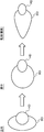
- FIG. 7 is a diagram for explaining the change over time of the circularity of the ball when the ball is dropped.
- FIG. 7 The left side of FIG. 7 shows the ball in the upper position, the right side of FIG. 7 shows the ball in the lower position (floor position), and the center of FIG. 7 shows the ball in the upper and lower positions ( (Floor position).
- FIG. 8 is a diagram showing an example of each time change of the ball area, the time differentiation of the ball area, the circularity of the ball, the temporal differentiation of the circularity of the ball, and the evaluation value when the ball is dropped. It is.
- ⁇ represents area D
- ⁇ time derivative of area (time change in area) dD
- ⁇ represents circularity S
- x time derivative of circularity S (circularity).
- FIG. 9 is a diagram for explaining a temporal change in the circularity of the trash box when the trash box falls.
- the left side of FIG. 9 shows the state of standing
- the right side of FIG. 9 shows the state of recumbent
- the center of FIG. 9 shows the state between these standing and recumbent.
- Each upper stage in FIG. 9 shows a side view thereof
- each lower stage shows a top view thereof.
- the sensor device SUa samples the output of the Doppler sensor 11 of the sensor unit 1 and acquires the image by the camera 12 to detect the fall of the monitored person Ob by operating as follows. is doing.
- control processing unit 3a acquires an image from the camera 12 of the sensor unit 1 (S1). That is, an image for one frame is acquired from the camera 12.
- control processing unit 3a uses, for example, a background subtraction method or an interframe subtraction method from the image acquired by the camera 12 by the moving body extraction unit 321 of the behavior detection processing unit 32 to monitor the subject Ob.
- a moving body region is extracted as the human body region (S2).
- control processing unit 3a uses the head candidate extraction unit 322a of the behavior detection processing unit 32 from the moving body region extracted by the moving body extraction unit 321 by using a technique such as Hough transform or pattern matching, for example.
- a candidate head region is extracted (S3).
- the control processing unit 3a uses the parameter calculation unit 323a of the behavior detection processing unit 32 in each of a plurality of preset parameters related to the head with respect to the head candidate region extracted by the head candidate extraction unit 322a.
- Each time change is obtained (S4).
- the parameter calculation unit 323a obtains the area D and the circularity S of the head candidate region as the plurality of parameters, and obtains the respective time changes dD and dS. More specifically, the parameter calculation unit 323a obtains the total number of pixels (total number of pixels) included in the head candidate area EHA extracted by the head candidate extraction unit 322a, for example, as illustrated in FIG.
- the area D of the head candidate region is obtained, and the total number of pixels constituting the outer periphery of the head candidate region EHA extracted by the head candidate extraction unit 322a ( By calculating the total number of pixels located at the boundary) (total number of pixels) and multiplying the total number of pixels thus determined by the length of one pixel (for example, vertical length, horizontal length, diagonal length, or an average value thereof)
- D and circularity S are set, for example, at the sampling timing (sample) Ing the number of timing) and in association with the frame number and the like stored in the storage unit 5a.
- the circularity S indicates that the closer the value is to 1, the closer it is to a perfect circle.
- the parameter calculation unit 323a calculates the area D (N-1) and the circularity S (N-1) of the head candidate region EHA obtained at the previous (N-1) sampling timing, and the current (N) By obtaining the difference between the area D (N) and the circularity S (N) of the head candidate area EHA obtained at the sampling timing, the time change (time differentiation) dD of the area D and the time change of the circularity S are obtained.
- Each dS is obtained, and the obtained time change dD of the area D of the head candidate region EHA and the time change dS of the circularity S are associated with, for example, the time of the sampling timing (number of sampling timings), the frame number, In addition, it is stored in the storage unit 5a.
- the control processing unit 3a determines the presence or absence of a fall in the monitored person Ob based on each time change in each of the plurality of parameters obtained by the parameter calculation unit 323a by the fall detection unit 324a of the behavior detection processing unit 32. Then, the fall of the monitored person Ob is detected (S5).
- the fall detection unit 324a obtains a time change dVa of the preset evaluation value Va based on a plurality of parameters obtained by the parameter calculation unit 323a, and based on the time change dVa of the obtained evaluation value Va. The fall of the monitored person Ob is detected.
- the middle posture in the middle of FIG. 5 is changed to the recumbent posture (right side in FIG. 5).
- the area of the head is away from the position where the camera 12 is arranged.
- the shape of the head gradually decreases as shown in the center and the right side, and the shape of the head changes from a substantially circular shape shown in the left side of FIG. 5 to a shape shown in the center of FIG. Change to shape.
- each of the head area D ( ⁇ ) and the circularity S ( ⁇ ) has the profile shown in FIG. 6, and both the frame numbers 1 to 5 before the fall are not so much changed, and the falls Both start to become smaller at frame number 6 where the start of the movement starts, and after frame number 8 when the fall is over due to falling to the floor, both are less changed again.
- the ball BL goes from the upper position (left side in FIG. 7) to the floor position (right side in FIG. 7) through the middle state in FIG. .
- the area of the ball BL moves away from the arrangement position of the camera 12, so the left side, the center, and the right side of FIG.
- the shape of the ball BL remains circular as shown in the left side, center and right side of FIG. 7, but does not change. Therefore, as shown in the graph, the area D ( ⁇ ) of the ball BL becomes the profile shown in FIG.
- the circularity S ( ⁇ ) of the ball BL does not change so much after the frame number 8 falling on the floor, and the circularity S ( ⁇ ) of the ball BL becomes the profile shown in FIG. As described above, the time variation of the circularity S is different between the fall of the monitored person Ob and the fall of the ball BL.
- the inverted frustoconical trash can DP moves from the normal arrangement posture before the fall (left side in FIG. 9) to the middle of FIG. After the above state, the posture falls to the side lying on the floor (right side in FIG. 9).
- the area and shape of the trash bin DP is changed from the circular shape on the lower left side of FIG. The shape changes to a substantially trapezoidal shape on the lower right side of FIG.
- the area D of the inverted frustoconical trash box DP gradually increases when the overturn starts, while the circularity S suddenly increases from 1 to 0 when the overturn starts. Get closer to.
- the time change of the area D and the time change of the circularity S between the fall of the monitored person Ob and the fall of the trash can DP.
- the fall detection unit 324a compares these differences with each other based on the time change dD of the area D and the time change dS of the circularity S in the head candidate region, so that the fall of the monitored subject Ob
- the fall of the monitored person Ob can be detected by discriminating whether the event has occurred in other than the monitoring person Ob.
- the fall of the monitored person Ob may be determined based on the time change of the area D ( ⁇ ) and the time change of the circularity S ( ⁇ ), but the evaluation value Va ( ⁇ ) obtained by multiplication of these time derivatives. 6), as can be seen by comparing FIG. 6 and FIG. 8, in FIG. 6, it rises from frame number 5 where the fall started, peaks at frame numbers 6 and 7, and falls at frame number 8, but in FIG. There is no such change. Therefore, the fall of the monitored person Ob is determined by the evaluation value Va rather than the fall of the monitored person Ob by the time change dD of the area D ( ⁇ ) and the time change dS of the circularity S ( ⁇ ). It is easier to determine.
- the fall detection unit 324a detects the presence or absence of a fall in the monitored person Ob based on the presence or absence of a change that occurs in the time change dVa of the evaluation value Va. In this case, when there is no change in the time change dVa of the evaluation value Va, the fall detection unit 324a determines that the monitored person Ob has not fallen, and there is a change in the time change dVa of the evaluation value Va. In this case, the fall detection unit 324a determines that the monitored person Ob has fallen.
- the fall detection unit 324a obtains a time change dVa of the preset evaluation value Va based on the plurality of parameters, and the time change dVa of the obtained evaluation value Va is within a preset threshold range. (Th1 ⁇ dVa ⁇ th2), the fall is determined. When the time change dVa of the evaluation value Va is not within the threshold range (th1> dVa, dVa> th2), the fall detection unit 324a determines that the monitored person Ob has not fallen, while the evaluation value When the time change dVa of Va is within the threshold range (th1 ⁇ dVa ⁇ th2), the fall detection unit 324a determines that the monitored person Ob has fallen.
- the upper and lower limit values th1 and th2 of the threshold range are set so that, for example, a fall can be determined based on the head from a plurality of samples.
- step S5 If no fall is detected as a result of the determination in step S5 (No), the process at this timing is terminated. On the other hand, if a fall is detected (Yes), the fall detection unit 324a The notification processor 33 is notified of the fall of Ob.
- the notification processing unit 33 notifies the management server device SV to that effect by the monitoring information communication signal described above, and performs processing at this timing. finish.
- the monitored person monitoring system MSa and the sensor apparatus SUa of the example using the action detecting apparatus and the action detecting method in the first embodiment which is an example of the monitored person monitoring apparatus are included in the head candidate region.
- the head candidate area is used to detect the monitored person Ob more accurately. A fall can be detected.
- the monitored person monitoring system MSa and the sensor device SUa are not only based on the time change dD in the area of the head candidate region, but also based on the time change of a preset subparameter related to the shape of the head candidate region. Thus, since the fall of the monitored person Ob is detected, the head and the other parts except the head can be more discriminated, and the fall of the monitored person Ob can be detected with higher accuracy.
- the monitored person monitoring system MSa and the sensor device SUa can easily determine the presence or absence of a fall by comparing the time change dVa of the evaluation value Va with the upper and lower limit values th1 and th2 that define the threshold range.
- the circularity S is used as a sub-parameter related to the shape, but is not limited to this.
- the aspect ratio of the head candidate area may be used as a sub-parameter related to the shape
- the skin area ratio of the head candidate area may be used
- the hair area ratio of the head candidate area may be used. May be.
- a plurality of the circularity of the head candidate region, the aspect ratio of the head candidate region, the skin area ratio of the head candidate region, and the hair area ratio of the head candidate region may be used.
- the aspect ratio is the ratio of the first length along the first direction and the second length along the second direction orthogonal to the first direction.
- the skin area ratio is a ratio between the total area of the head candidate area and the area of the skin area (skin area) in the head candidate area.
- the hair area ratio is a ratio between the total area of the head candidate area and the area of the hair area (hair area) in the head candidate area.
- FIG. 10 is a diagram for explaining the temporal change in the aspect ratio of the head during a fall.
- FIG. 10A is a top view of the head as seen from above
- FIG. 10B is a front view of the head as seen from the front.
- FIG. 11 is a diagram for explaining the total head height, head length, and head width.
- FIG. 11A is a side view
- FIG. 11B is a front view.
- FIG. 12 is a diagram for explaining temporal changes in the skin area ratio of the head and the hair area ratio during a fall.
- the left side of FIG. 12 shows a standing state
- the right side of FIG. 12 shows a lying state
- the center of FIG. 12 shows a state between these standing and lying sides.
- FIG. 13 is a diagram for explaining how to obtain the skin area ratio of the head and the hair area ratio.
- the aspect ratio is used as the subparameter, in the image acquired by the camera 12 that images the monitored person Ob from above the monitored person Ob, the head is shown in FIG. 10A in the standing posture before the fall. As shown in FIG. 11, the aspect ratio is the head width relative to the head length.
- Statistical data on the size of each part of a person is created and released by, for example, a public institution. For example, statistical data on the Japanese head is disclosed by the Digital Human Research Group, National Institute of Advanced Industrial Science and Technology (Human Information Research Division) ([online], search on April 23, 2015, Internet ⁇ http: // www .Dh.aist.go.jp / jp / pubbase / data.php>).
- the head length is 188 mm
- the time change of the aspect ratio of the trash can can take a value between 1 and 0.
- the fall detection unit 324a can determine that the fall has occurred when the temporal change in the aspect ratio is within a preset threshold range. In this case, if the time change of the aspect ratio is not within the threshold range, the fall detection unit 324a determines that the monitored person Ob has not fallen, while the time change of the aspect ratio is within the threshold range. If it is, the fall detection unit 324a determines that the monitored person Ob has fallen.
- the lower limit value is 0.687
- the upper limit value is 0.840
- the fall detection unit 324a has an aspect ratio time change of 0.687 or more and 0.840 or less. In some cases, the fall can be determined.
- the temporal change in the hair area ratio can be used as a sub-parameter, and the skin area and the hair area can be detected by known conventional means, for example, as shown in FIG.
- the block is divided into small blocks, and for each block, it is determined whether the block is an area where the hair is copied or an area where the skin is copied, which is determined by whether the block has a texture as shown in FIG. 13C, it can be determined by whether or not it has a texture as a feature.
- Approach can be determined by various known techniques determination method or the like using the determination method and Fourier transform based on the co-occurrence matrix.
- the size of the head region shown in the image does not change much. For this reason, if it is attempted to determine whether or not there is a fall based only on the size of the head region shown in the image, it is difficult to determine whether it is a fall or a movement in the horizontal direction.
- the second embodiment deals with such a case.
- the monitored person monitoring apparatus includes an action detection unit that detects a predetermined action set by a monitored person who is a monitoring target, and the predetermined action detected by the action detection unit. And a notification unit for notifying the device. And in 2nd Embodiment, the said action detection part is the distance from the image acquisition part which acquires the image imaged from the said to-be-monitored person, and the said to-be-monitored person's head above the to-be-monitored person.
- a distance measuring unit that measures from the above, a size calculating unit that calculates the size of the head of the monitored person viewed from above from the image acquired by the image acquiring unit, and the head that is determined by the size calculating unit And a fall detection unit that detects a fall in the monitored person based on a temporal change rate of a difference between the size of the monitor and the distance to the head measured by the ranging unit.
- the behavior detection unit is mounted on a sensor device SUb described later together with the notification unit will be described.
- the monitored person monitoring device can be configured in the same manner as described below.
- FIG. 14 is a diagram illustrating a configuration of a sensor device in the monitored person monitoring system according to the second embodiment.
- FIG. 15 is a diagram illustrating an arrangement of the sensor device in the monitored person monitoring system according to the second embodiment.
- the monitored person monitoring system MSb in the second embodiment of the example in which the monitored person monitoring device is realized as a system is the same as the monitored person monitoring system MSa of the first embodiment.
- a predetermined action set in Ob (Ob-1 to Ob-4) is detected to monitor the monitored person Ob.
- the management server device SV, fixed terminal device SP, and one or more portable terminal devices TA (TA-1, TA-2) in the monitored person monitoring system MSb of the second embodiment are respectively the first embodiment. Since this is the same as the management server device SV, fixed terminal device SP, and one or more portable terminal devices TA (TA-1, TA-2) in the monitored person monitoring system MSa, the description thereof is omitted.
- the sensor device SUb is a device that has a communication function for communicating with other devices SV, SP, and TA via the network NW, detects the monitored person Ob, and transmits the detection result to the management server device SV.
- the sensor device SUb includes a sensor unit 1, a sound input / output unit 2, a control processing unit 3b, a communication interface unit (communication IF unit) 4, and a storage unit 5b. Is provided.
- the sensor unit 1, the sound input / output unit 2 and the communication IF unit 4 in the sensor device SUb of the second embodiment are respectively the sensor unit 1, the sound input / output unit 2 and the communication IF unit in the sensor device SUa of the first embodiment. Since it is the same as 4, its description is omitted.
- the predetermined quantities include the distance to the head of the monitored person Ob and are appropriately determined according to the predetermined action to be detected by the monitored person Ob.
- the storage unit 5b is a circuit that is connected to the control processing unit 3b and stores various predetermined programs and various predetermined data under the control of the control processing unit 3b.
- the various predetermined programs include, for example, control processing programs such as a monitoring processing program for executing information processing related to monitoring of the monitored person Ob.
- the monitoring processing program includes a behavior detection program for detecting a predetermined behavior in the monitored person Ob based on an output of the sensor unit 1, a notification processing program for notifying the predetermined behavior detected by the behavior detection program to the outside, By using the streaming processing program for streaming the moving image captured by the camera 12 to the fixed terminal device SP or the portable terminal device TA that requested the moving image, and the sound input / output unit 2 or the like, the fixed terminal device SP or the portable terminal A nurse call processing program for making a voice call with the device TA is included.
- the behavior detection program includes a moving body extraction program that extracts a moving body region as a human body region of the monitored person Ob from an image acquired by the camera 12 of the sensor unit 1, and a moving body region extracted from the moving body extraction program.
- the various types of predetermined data include data necessary for executing these programs, data necessary for monitoring the monitored person Ob, and the like.
- the storage unit 5b includes, for example, a ROM that is a nonvolatile storage element, an EEPROM that is a rewritable nonvolatile storage element, and the like.
- the storage unit 5b includes a RAM serving as a working memory of a so-called control processing unit 3b that stores data generated during execution of the predetermined program.
- the control processing unit 3b is a circuit for controlling each unit of the sensor device SUb according to the function of each unit and detecting predetermined amounts set in advance in the monitored person Ob.
- the control processing unit 3b includes, for example, a CPU and its peripheral circuits.
- the control processing unit 3b functionally includes a control unit 31, a behavior detection processing unit 32, a notification processing unit 33, a streaming processing unit 34, and a nurse call processing unit 35 by executing the control processing program.
- the processing unit 32 functionally includes a moving object extraction unit 321, a head extraction unit 322b, a size calculation unit 323b, a distance calculation unit 324b, and a fall detection unit 325b.
- the control unit 31 controls each part of the sensor device SUb according to the function of each part, and controls the entire sensor device SUb.
- the behavior detection processing unit 32 detects a predetermined behavior set in advance in the monitored person Ob based on the output of the sensor unit 1.
- the predetermined behavior is wakeup, getting out of bed, falling, and abnormal movement of the monitored person Ob
- the behavior detection processing unit 32 is based on the output of the sensor unit 1.
- Wake-up, getting-off, falling, and minute body movement abnormality in the monitoring person Ob are detected as detection results, and the detection results are notified to the notification processing unit 33.
- the behavior detection processing unit 32 detects wake-up, getting-off and abnormal body movement of the monitored person Ob based on the output of the sensor unit 1 by a known technique.
- the behavior detection processing unit 32 extracts a moving body region from the image acquired by the camera 12 of the sensor unit 1 as the human body region of the monitored person Ob, and the posture of the monitored person Ob from the aspect ratio of the extracted moving body area ( For example, standing position, sitting position, lying down, etc.) are detected, the position of the detected moving body region is detected, and the distinction between the rising and leaving is determined based on these determinations and the detected posture and position of the monitored person Ob.
- the behavior detection processing unit 32 detects body movement of the chest (vertical movement of the chest) accompanying the breathing motion of the monitored person Ob by the Doppler sensor 11 of the sensor unit 1, and the period disturbance in the body movement of the chest When the amplitude in the body motion of the chest that is equal to or less than a preset threshold is detected, it is determined that the minute motion abnormality is present.
- the behavior detection processing unit 32 includes a moving object extraction unit 321, a head extraction unit 322b, a size calculation unit 323b, a distance calculation unit 324b, and a fall detection unit 325b. Functionally provided, and these detect the fall of the monitored person Ob.
- the moving object extraction unit 321 extracts a moving object region from the image acquired by the camera 12 of the sensor unit 1 as a human body region of the monitored person Ob by using a method such as a background difference method or an inter-frame difference method.
- the moving object extraction unit 321 is also used when extracting a moving object in order to detect the above-described wake-up and getting-off, and is shared by these processes.
- a background image is obtained in advance and stored in advance in the storage unit 5b as one of the various predetermined data, and the presence / absence of moving objects is determined from the difference image between the image generated by the camera 12 and the background image. If there is a moving object as a result of this determination, the area of the moving object is set as a moving object area.
- the presence / absence of a moving object is determined from a difference image between an image of a current frame and an image of a past frame (for example, the previous frame) generated by the camera 12. If there is a moving object region, this moving object region is set as the moving object region.
- the moving object extraction unit 321 notifies the extracted moving object region to the head extraction unit 322b.
- the head extraction unit 322b extracts a head region (a head region or a head candidate region) from the moving object region extracted by the moving object extraction unit 321.
- a head shape pattern is prepared in advance and stored in advance in the storage unit 5b as one of the various predetermined data, and the head extraction unit 322b is stored in the storage unit 5b in advance.
- a pattern is searched from the body movement area by using pattern matching, and an area matching the shape pattern of the head is extracted as the head area.
- the head is reflected in an image captured from above in a substantially circular shape corresponding to the top of the head. Therefore, a substantially circular pattern is one of the head shape patterns. included.
- the head extraction unit 322b notifies the size calculation unit 323b of the extracted head region.
- the size calculation unit 323b obtains the size of the head of the monitored person Ob seen from above by obtaining the area of the head region extracted by the head extraction unit 322b. For example, the size calculation unit 323b calculates the total number of pixels (total number of pixels) included in the head region extracted by the head extraction unit 322b, and multiplies the calculated total number of pixels by the area of one pixel. The area of the head region is obtained, and the size of the head is obtained. The size calculation unit 323b notifies the fall detection unit 325b of the obtained head size.
- the size calculation unit 323b corresponds to another example of the parameter calculation unit.
- the distance calculation unit 324b obtains the distance to the head of the monitored person Ob by obtaining the distance from the Doppler signal output from the Doppler sensor 11 of the sensor unit 1.
- the distance calculation is performed.
- the distance obtained by the part 324b increases substantially monotonously with time and becomes a relatively large value.
- the distance obtained by the distance calculation unit 324b is a value resulting from the body movement of the chest accompanying the breathing motion of the monitored person Ob.
- the monitored person Ob when the monitored person Ob is normal, it changes periodically with the passage of time and becomes a relatively small value. For this reason, it can be distinguished whether the distance calculated
- the fall detection unit 325b detects a fall in the monitored person Ob based on the time change rate of the difference between the size of the head obtained by the size calculation unit 323b and the distance to the head obtained by the distance calculation unit 324b. To do. When the fall detection unit 325b detects the fall of the monitored person Ob, the fall detection unit 325b notifies the notification processing unit 33 accordingly.
- the Doppler sensor 11 and the distance calculation unit 324b correspond to an example of a distance measurement unit
- the camera 12 corresponds to an example of an image acquisition unit.
- the control processing unit 3b includes a control unit 31, a behavior detection processing unit 32, a notification processing unit 33, a streaming processing unit 34, and a nurse call processing unit 35.
- the behavior detection processing unit 32 a moving object extraction unit 321, a head extraction unit 322b, a size calculation unit 323b, a distance calculation unit 324b, and a fall detection unit 325b are functionally configured.
- the general operation in the monitored person monitoring system MSb configured as described above for monitoring each monitored person Ob is the same as that in the first embodiment, except for the operation of overturn detection in the sensor device SUb. Description is omitted.
- FIG. 16 is a flowchart illustrating the operation of the sensor device in the monitored person monitoring system according to the second embodiment.
- FIG. 17 is a diagram for explaining the temporal change of the head region during a fall. The left side of FIG. 17 shows the standing position before the fall, the right side of FIG. 17 shows the lying side after the fall, and the center of FIG. 17 shows the state between the standing position and the lying side (state during the fall) ).
- FIG. 18 is a diagram illustrating an example of changes over time in the distance to the head and the size of the head region during a fall.
- FIG. 17 is a diagram for explaining the temporal change of the head region during a fall. The left side of FIG. 17 shows the standing position before the fall, the right side of FIG. 17 shows the lying side after the fall, and the center of FIG. 17 shows the state between the standing position and the lying side (state during the fall) ).
- FIG. 18 is a diagram illustrating an example of changes over time in the distance to the head and the size of the head region
- FIG. 19 is a diagram illustrating an example of changes over time in the distance to the head and the size of the head region during normal horizontal (lateral) movement.
- FIG. 20 is a diagram illustrating an example of changes over time of the distance to the head and the size of the head region during normal vertical (vertical) movement.
- the horizontal axis is time
- the right vertical axis is the size of the head
- the left vertical axis is the distance.
- Graphs ⁇ 1, ⁇ 2, and ⁇ 3 show the relationship between time and the distance to the head
- graphs ⁇ 1, ⁇ 2, and ⁇ 3 show the relationship between time and the size of the head.
- the sensor device SUb samples the output of the Doppler sensor 11 of the sensor unit 1 and acquires the image with the camera 12 to detect the fall of the monitored person Ob by operating as follows. is doing.
- the control processing unit 3b acquires a Doppler signal from the Doppler sensor 11 of the sensor unit 1, and acquires an image (image for one frame) from the camera 12 of the sensor unit 1 (S11).
- control processing unit 3b uses a technique such as a background subtraction method or an interframe subtraction method from the image acquired by the camera 12 by the moving body extraction unit 321 of the behavior detection processing unit 32, for example.
- the moving body region is extracted as the human body region (S12).
- control processing unit 3b uses a method such as pattern matching from the moving body region extracted by the moving body extraction unit 321 by the head extraction unit 322b of the behavior detection processing unit 32, for example. Partial area) is extracted (S13).
- This head region may be a head candidate region, as in the first embodiment.
- the control processing unit 3b obtains the size (area) of the head region extracted by the head extraction unit 322b by the size calculation unit 323b of the behavior detection processing unit 32 (S14).
- the size calculation unit 323b calculates the total number of pixels (total number of pixels) included in the head region extracted by the head extraction unit 322b, and multiplies the calculated total number of pixels by the area of one pixel.
- the area ⁇ of the head region is obtained as its size, and the obtained area ⁇ of the head region is stored in the storage unit 5b in association with, for example, the sampling timing (number of sampling timings), the frame number, and the like.
- the control processing unit 3b uses the distance calculation unit 324b of the behavior detection processing unit 32 to obtain the distance as the distance ⁇ from the Doppler signal acquired in step S11, and the obtained distance ⁇ to the head. For example, it is stored in the storage unit 5b in association with the time of sampling timing (number of times of sampling timing), the frame number, etc. (S15). That is, the area ⁇ of the head region obtained in step S14 and the distance ⁇ to the head obtained in step S15 are associated with each other via, for example, the time of sampling timing (the number of sampling timings), the frame number, and the like. It is stored in the storage unit 5b.
- control processing unit 3b sets the head region size ⁇ calculated by the size calculation unit 323b and the distance ⁇ to the head calculated by the distance calculation unit 324b by the fall detection unit 325b of the behavior detection processing unit 32. Based on this, the presence or absence of a fall in the monitored person Ob is determined, and the fall in the monitored person Ob is detected (S16).
- the distance ⁇ 2 to the head and the size ⁇ 2 of the head region in each case, and the distance to the head when the monitored object Ob moves in the vertical direction (vertical direction) due to, for example, squatting Changes with time in each of ⁇ 3 and head region size ⁇ 3 will be described with reference to FIGS.
- the sensor unit 1 is disposed on the ceiling of the living room RM, for example, and the monitored person is viewed from above the monitored person Ob. Since Ob is sensed, the distance ⁇ 2 to the head changes so as to monotonously increase with time, and becomes, for example, a solid line graph ⁇ 2 shown in FIG. 19, and the size of the head (head region) on the image. The length ⁇ 2 changes so as to become slightly smaller as time elapses, for example, a broken line graph ⁇ 2 shown in FIG.
- the sensor unit 1 senses the monitored person Ob from above the monitored person Ob as described above. For example, a solid line graph ⁇ 3 shown in FIG. 20 is obtained, and the size ⁇ 3 of the head (head region) on the image decreases monotonously with time. For example, a broken line graph ⁇ 3 shown in FIG. 20 is obtained.
- the size ⁇ 1 of the head (head region) on the image is reduced as the head moves away from the camera 12 because the approximate top of the head appears in the image in the middle of the fall. It changes a lot. However, since the profile of the head appears in the image at the end from the middle of the fall, the size ⁇ 1 of the head (head region) on the image decreases as the head moves away from the camera 12. The change does not change so much by offsetting the change that increases with the change from the top to the profile. For this reason, the size ⁇ 1 of the head (head region) on the image changes relatively large so as to decrease monotonically with the passage of time from the start of the fall, and at the end of the fall from the end.
- the size ⁇ 1 of the head (head region) changes nonlinearly so as to gradually approach a predetermined value as time passes in the event of a fall.
- the difference between the distance ⁇ to the head and the size ⁇ of the head region ( ⁇ 1- ⁇ 1, ⁇ 2- ⁇ 2, ⁇ 3- ⁇ 3) only changes monotonically with the passage of time.
- Each case is difficult to distinguish based on the difference ( ⁇ 1- ⁇ 1, ⁇ 2- ⁇ 2, ⁇ 3- ⁇ 3) between the distance ⁇ to the head portion and the size ⁇ of the head region, but the time change rate (( ⁇ 1- ⁇ 1 ) / ⁇ T1, ( ⁇ 2- ⁇ 2) / ⁇ T2, ( ⁇ 3- ⁇ 3) / ⁇ T3) change only in the case of a fall, and the time change rate (( ⁇ 1- ⁇ 1) / ⁇ T1, ( ⁇ 2- Each case can be distinguished based on ⁇ 2) / ⁇ T2 and ( ⁇ 3- ⁇ 3) / ⁇ T3).
- the distance ⁇ 1 to the head and the size ⁇ 1 of the head (head region) at the sampling timings T11, T12, T13, and T14 are respectively ⁇ 1 (T11) and ⁇ 1 (T12).
- the fall detection unit 325b calculates the difference between the head region size ⁇ obtained by the size calculation unit 323b and the distance ⁇ to the head obtained by the distance calculation unit 324b. Based on the time change rate, the presence or absence of a fall in the monitored person Ob is determined, and the fall in the monitored person Ob is detected. More specifically, the fall detection unit 325b calculates the difference between the head region size ⁇ obtained by the size calculation unit 323b and the distance ⁇ to the head obtained by the distance calculation unit 324b at the previous sampling timing.
- the time change rate is compared with the time change rate of the difference between the head region size ⁇ obtained by the size calculator 323b and the distance ⁇ obtained by the distance calculator 324b at the current sampling timing. If there is a change in the time change rate of the difference, the fall detection unit 325b determines that the monitored person Ob has fallen, and if there is no change in the time change rate of the difference, the fall detection unit 325b. Determines that the monitored person Ob has not fallen.
- step S16 if no fall is detected (No), the process at this timing is terminated. On the other hand, if a fall is detected (Yes), the fall detection unit 325b detects the person being monitored. The notification processor 33 is notified of the fall of Ob (S17).
- the notification processing unit 33 notifies the management server device SV to that effect by the above-described monitoring information communication signal, and performs processing at this timing. finish.
- the monitored person monitoring system MSb which is an example of the monitored person monitoring apparatus
- the sensor apparatus SUb of the example using the action detecting apparatus and the action detecting method have the size of the head (head region). Since the fall of the monitored person Ob is detected based on the time change rate of the difference between ⁇ 1 and the distance ⁇ 1 to the head, the fall of the monitored person Ob can be detected with higher accuracy.
- the monitored person monitoring system MSb and the sensor device SUb use an infrared camera as the camera 12 of the sensor unit 1, the fall of the monitored person Ob can be detected even in the dark.
- the Doppler sensor mounted as a sensor for detecting a minute movement abnormality can also be used as a distance measurement sensor. There is no need to provide it.
- the sensor devices SUa and SUb include the behavior detection unit and the notification unit.
- the behavior detection unit and the notification unit are included in the management server device SV.
- it may be provided in the fixed terminal device SP, or may be provided in the mobile terminal device TA.
- a communication interface that receives and acquires a communication signal containing an image captured from above the monitored person from the sensor devices SUa and SUb via the network NW corresponds to an example of an image acquisition unit. become.
- the monitored person monitoring apparatus includes an image acquisition unit that acquires an image of the monitored person that is a monitoring target from above the monitored person, and an image acquired by the image acquisition unit.
- a head candidate extraction unit that extracts a head candidate region that is a candidate for the head, and each time change in each of a plurality of preset parameters related to the head with respect to the head candidate region extracted by the head candidate extraction unit
- a fall detection unit that detects a fall in the monitored person based on each time change in each of the plurality of parameters obtained by the parameter computation unit, and at least one of the parameters is , Extracted from the image acquired by the image acquisition unit.
- the image is expected to be located at the head of the monitored person in the bedding on which the monitored person is lying down.
- the image is taken from directly above the preset head planned position.
- the head is reflected in a substantially circular shape in the image captured from above, and thus a circular region is detected as the head region.
- a substantially circular object that is not the head such as a pillow, a washbasin, a ball, a trash can, and a futon handle is also reflected, so the area of these objects is erroneously detected as the head area, A fall may be erroneously detected.
- the erroneous detection can be avoided by removing the area of these objects at the fixed position from the area for detecting the head in advance.
- the fall detection device obtains each time change in each of a plurality of parameters related to the head with respect to the head candidate area, and detects a fall in the monitored person based on each time change. It is possible to detect the fall of the monitored person with higher accuracy.
- the plurality of parameters are an area of the head candidate region and a preset subparameter related to the shape of the head candidate region.
- the sub-parameters include the circularity of the head candidate region, the aspect ratio of the head candidate region, the skin area ratio of the head candidate region, and the hair of the head candidate region.
- the circularity is a degree representing how close to a perfect circle.
- the aspect ratio is the ratio of the first length along the first direction and the second length along the second direction orthogonal to the first direction.
- the skin area ratio is a ratio between the total area of the head candidate area and the area of the skin area (skin area) in the head candidate area.
- the hair area ratio is a ratio between the total area of the head candidate area and the area of the hair area (hair area) in the head candidate area.
- Such a fall detection device is not only based on a temporal change in the area of the head candidate area, but also based on a time change of a preset subparameter related to the shape of the head candidate area. Therefore, it is possible to discriminate the head from other parts except the head, and to detect the fall of the monitored person with higher accuracy.
- the fall detection unit obtains a time change of an evaluation value set in advance based on the plurality of parameters, and the time change of the obtained evaluation value is set in advance. If it falls within the set threshold range, the fall is determined.
- Such a fall detection device can easily determine whether or not a fall has occurred by comparing the time variation of the evaluation value with the upper and lower limit values that define the threshold range.
- the fall detection device further includes a distance measuring unit that measures a distance to the head of the monitored person from above the monitored person
- the parameter calculation unit includes the image acquisition
- a size calculation unit that obtains, as the parameter, the size of the head of the person to be monitored as viewed from above from the image acquired by the unit
- the fall detection unit includes the size of the head calculated by the size calculation unit The fall of the monitored person is detected based on the time change rate of the difference between the size and the distance to the head measured by the distance measuring unit.
- the size of the head region shown in the image greatly changes so as to become smaller as the head moves away from the camera.
- the profile of the head appears in the image from the middle of the fall to the end thereof, the size of the head region reflected in the image changes as the head moves away from the camera and the profile from the top It does not change much by offsetting the change that grows with the change to.
- the size of the head region shown in the image does not change much.
- the fall detection device detects a fall in the monitored person based on a time change rate of a difference between the size of the head and the distance to the head, the fall of the monitored person is more accurately detected. It can be detected well.
- the image acquisition unit is an infrared camera.
- Such a fall detection device uses an infrared camera, it is possible to detect the fall of the monitored person even in the dark.
- the distance measuring unit includes a Doppler sensor and a distance calculation unit that obtains a distance from a Doppler signal of the Doppler sensor.
- the Doppler sensor can be used in the monitored person monitoring device as a sensor for detecting abnormal movement of the monitored person. Since the fall detection device uses this Doppler sensor for distance measurement, it is not necessary to provide a distance measurement sensor separately when it is incorporated in a monitored person monitoring device equipped with a Doppler sensor as a sensor for detecting minute movement abnormality. .
- the fall detection method includes an image acquisition step of acquiring an image of a monitored person to be monitored from above the monitored person, and a head from the image acquired in the image acquisition step.
- a head candidate extraction step for extracting a head candidate region that is a candidate for the head, and each time change in each of a plurality of preset parameters related to the head with respect to the head candidate region extracted in the head candidate extraction step
- a fall detection step of detecting a fall in the monitored person based on each time change in each of the plurality of parameters obtained in the parameter calculation step.
- Such a fall detection method obtains each time change in each of a plurality of parameters related to the head with respect to the head candidate region, and detects a fall in the monitored person based on each time change.
- the fall of the monitored person can be detected with higher accuracy using the area.
- a monitored person monitoring apparatus includes a behavior detection unit that detects a predetermined behavior of a monitored person that is a monitoring target, and a notification unit that notifies the predetermined behavior detected by the behavior detection unit to the outside
- the predetermined behavior includes a fall
- the behavior detection unit includes any of the above-described fall detection devices.
- a fall detection device a fall detection method, and a monitored person monitoring device using the fall detection device can be provided.
Abstract
本発明の転倒検知装置および該方法ならびに被監視者監視装置では、監視対象である被監視者を、前記被監視者の上方から撮像した画像が取得され、前記画像から、頭部の候補となる頭部候補領域が抽出され、前記頭部候補領域に対し、頭部に関わる予め設定された複数のパラメータそれぞれにおける各時間変化が求められ、前記複数のパラメータそれぞれにおける各時間変化に基づいて前記被監視者における転倒が検知される。
Description
本発明は、監視すべき監視対象である被監視者の転倒を検知する転倒検知装置および転倒検知方法に関する。そして、本発明は、この転倒検知装置を用いた被監視者監視装置に関する。
我が国(日本)は、戦後の高度経済成長に伴う生活水準の向上、衛生環境の改善および医療水準の向上等によって、高齢化社会、より詳しくは、総人口に対する65歳以上の人口の割合である高齢化率が21%を超える超高齢化社会になっている。また、2005年では、総人口約1億2765万人に対し65歳以上の高齢者人口は、約2556万人であったのに対し、2020年では、総人口約1億2411万人に対し高齢者人口は、約3456万人となる予測もある。このような高齢化社会では、病気や怪我や高齢等による看護や介護を必要とする要看護者や要介護者(要看護者等)は、高齢化社会ではない通常の社会で生じる要看護者等よりもその増加が見込まれる。そして、我が国は、例えば2013年の合計特殊出生率が1.43という少子化社会でもある。そのため、看護や介護の必要な高齢者を高齢の家族(配偶者、子、兄弟)が介護する老老介護も起きて来ている。
要看護者や要介護者は、病院や、老人福祉施設(日本の法令では老人短期入所施設、養護老人ホームおよび特別養護老人ホーム等)等の施設に入所し、その看護や介護を受ける。このような施設では、要看護者等が、例えばベッドからの転落や歩行中の転倒等によって怪我を負ったり、ベッドから抜け出して徘徊したりするなどの問題がある。このような事態に対し、可及的速やかに対応する必要があり、また、このような事態を放置しておくとさらに大きな問題に発展してしまう可能性もあるため、前記施設では、看護師や介護士等は、定期的に巡視することによってその安否や様子を確認している。
しかしながら、要看護者等の増加数に対し看護師等の増加数が追い付かずに、看護業界や介護業界では、慢性的に人手不足になっている。さらに、日勤の時間帯に較べ、準夜勤や夜勤の時間帯では、看護師や介護士等の人数が減るため、一人当たりの業務負荷が増大するので、前記業務負荷の軽減が要請される。また、前記老老介護の事態は、前記施設でも例外ではなく、高齢の要看護者等を高齢の看護師等がケアすることもしばしば見られる。一般に高齢になると体力が衰えるため、健康であっても若い看護師等に比し看護等の負担が重くなり、また、その動きや判断も遅くなる。
このような人手不足や看護師等の負担を軽減するため、看護業務や介護業務を補完する技術が求められている。このため、近年では、要看護者等の、監視すべき監視対象である被監視者を監視(モニタ)する被監視者監視装置が研究、開発されている。
このような技術の一つとして、例えば特許文献1に開示された転倒検知装置がある。この特許文献1に開示された転倒検知装置は、カメラと、カメラが出力する映像信号を取り込み、取り込まれた画像に対して差分処理を行う画像処理手段と、差分処理によって得られた差分領域の面積に基づいて人体の転倒動作を検知する判断手段とからなる。より具体的には、前記判断手段は、人体における単位時間当たりの面積変化で転倒の有無を判断している。
一方、安否確認の点では、一人暮らしの独居者も前記要看護者等と同様であり、監視対象である被監視者となる。
ところで、転倒の有無によって画像に写る人体の領域の大きさが変化するので、前記特許文献1に開示された転倒検知装置は、人体領域における単位時間当たりの面積変化で転倒を検知しているが、転倒の有無によって画像に写る頭部の領域の大きさも変化するので、頭部領域の大きさによって転倒を検知する手法が考えられる。
本発明は、上述の事情に鑑みて為された発明であり、その目的は、被監視者を上方から撮像した画像に基づき被監視者の転倒をより精度良く検知できる転倒検知装置および転倒検知方法ならびにこの転倒検知装置を用いた被監視者監視装置を提供することである。
本発明にかかる転倒検知装置および転倒検知方法ならびに被監視者監視装置では、監視対象である被監視者を、前記被監視者の上方から撮像した画像が取得され、前記画像から、頭部の候補となる頭部候補領域が抽出され、前記頭部候補領域に対し、頭部に関わる予め設定された複数のパラメータそれぞれにおける各時間変化が求められ、前記複数のパラメータそれぞれにおける各時間変化に基づいて前記被監視者における転倒が検知される。したがって、本発明にかかる転倒検知装置および転倒検知方法ならびに被監視者監視装置は、被監視者を上方から撮像した画像に基づき被監視者の転倒をより精度良く検知できる。
上記並びにその他の本発明の目的、特徴及び利点は、以下の詳細な記載と添付図面から明らかになるであろう。
以下、本発明にかかる実施の一形態を図面に基づいて説明する。なお、各図において同一の符号を付した構成は、同一の構成であることを示し、適宜、その説明を省略する。本明細書において、総称する場合には添え字を省略した参照符号で示し、個別の構成を指す場合には添え字を付した参照符号で示す。
本被監視者監視装置は、監視対象である被監視者における、予め設定された所定の行動を検知する行動検知部と、前記行動検知部で検知した前記所定の行動を外部に通知する通知部とを備えるものである。このような被監視者監視装置は、1個の機器として、一体に構成されて実現されて良く、また、システムとして、複数の機器で実現されて良い。そして、被監視者監視装置が複数の機器で実現される場合に、前記行動検知部は、これら複数の機器のうちのいずれに実装されて良い。一例として、ここでは、前記被監視者監視装置がシステムとして複数の機器で実現されている場合について、前記被監視者監視装置の第1および第2実施形態それぞれを説明する。第1実施形態における被監視者監視装置は、監視対象である被監視者を、前記被監視者の上方から撮像した画像を取得する画像取得部と、前記画像取得部で取得した画像から、頭部の候補となる頭部候補領域を抽出する頭部候補抽出部と、前記頭部候補抽出部で抽出した頭部候補領域に対し、頭部に関わる予め設定された複数のパラメータそれぞれにおける各時間変化を求めるパラメータ演算部と、前記パラメータ演算部で求めた複数のパラメータそれぞれにおける各時間変化に基づいて前記被監視者における転倒を検知する転倒検知部とを備え、前記パラメータのうちの少なくとも1つは、前記画像取得部で取得した画像から抽出されたものである。第2実施形態における被監視者監視装置は、前記被監視者の頭部までの距離を、前記被監視者の上方から測定する測距部をさらに備え、前記パラメータ演算部は、前記画像取得部で取得した画像から、前記上方から見込んだ前記被監視者の頭部の大きさを前記パラメータとして求めるサイズ演算部を備えて構成され、前記転倒検知部は、前記サイズ演算部で求めた前記頭部の大きさと前記測距部で測定した前記頭部までの距離との差分の時間変化率に基づいて前記被監視者における転倒を検知する。なお、前記被監視者監視装置が1個の機器として一体に構成されて実現される場合についても、以下の説明と同様に、前記被監視者監視装置を構成できる。また、一例として、ここでは、前記行動検知部が前記通知部と共に後述のセンサ装置SUa、SUbに実装される場合について、説明するが、このシステムのうちの他の装置、例えば後述の管理サーバ装置SV、固定端末装置SPあるいは携帯端末装置TAに実装される場合についても、以下の説明と同様に、前記被監視者監視装置を構成できる。
(第1実施形態)
上述した、頭部領域の大きさによって転倒を検知する手法において、上方から撮像した画像では、頭部は、略円形状に写るので、画像から円形状の領域が頭部領域として検出される。しかしながら、実際の画像には、枕、洗面器、ボール、ゴミ箱および布団の柄等の頭部ではない略円形状の物体も写り込むため、これらの物体の領域が頭部領域として誤検出され、転倒が誤検知されてしまう場合がある。一方、これらの物体が定位置に存在すれば、定位置にあるこれら物体の領域を、頭部を検出する領域から予め除くことで、前記誤検知が回避できる。しかしながら、これらの物体は、必ずしも定位置に存在するとは、限らない。第1実施形態は、このような場合に対処するものである。
上述した、頭部領域の大きさによって転倒を検知する手法において、上方から撮像した画像では、頭部は、略円形状に写るので、画像から円形状の領域が頭部領域として検出される。しかしながら、実際の画像には、枕、洗面器、ボール、ゴミ箱および布団の柄等の頭部ではない略円形状の物体も写り込むため、これらの物体の領域が頭部領域として誤検出され、転倒が誤検知されてしまう場合がある。一方、これらの物体が定位置に存在すれば、定位置にあるこれら物体の領域を、頭部を検出する領域から予め除くことで、前記誤検知が回避できる。しかしながら、これらの物体は、必ずしも定位置に存在するとは、限らない。第1実施形態は、このような場合に対処するものである。
図1は、実施形態における被監視者監視システムの構成を示す図である。図2は、第1実施形態の被監視者監視システムにおけるセンサ装置の構成を示す図である。
前記被監視者監視装置をシステムとして実現したその一例の第1実施形態における被監視者監視システムMSaは、監視すべき(見守るべき)監視対象(見守り対象)である被監視者(見守り対象者)Ob(Ob-1~Ob-4)における、予め設定された所定の行動を検知して前記被監視者Obを監視するものであり、例えば、図1に示すように、1または複数のセンサ装置SUa(SUa-1~SUa-4)と、管理サーバ装置SVと、固定端末装置SPと、1または複数の携帯端末装置TA(TA-1、TA-2)とを備え、これらは、有線や無線で、LAN(Local Area Network)、電話網およびデータ通信網等の網(ネットワーク、通信回線)NWを介して通信可能に接続される。ネットワークNWには、通信信号を中継する例えばリピーター、ブリッジ、ルーターおよびクロスコネクト等の中継機が備えられても良い。図1に示す例では、これら複数のセンサ装置SUa-1~SUa-4、管理サーバ装置SV、固定端末装置SPおよび複数の携帯端末装置TA-1、TA-2は、アクセスポイントAPを含む無線LAN(例えばIEEE802.11規格に従ったLAN等)NWによって互いに通信可能に接続されている。
被監視者監視システムMSaは、被監視者Obに応じて適宜な場所に配設される。被監視者(見守り対象者)Obは、例えば、病気や怪我等によって看護を必要とする者や、身体能力の低下等によって介護を必要とする者や、一人暮らしの独居者等である。特に、早期発見と早期対処とを可能にする観点から、被監視者Obは、例えば異常状態等の所定の不都合な事象がその者に生じた場合にその発見を必要としている者であることが好ましい。このため、被監視者監視システムMSaは、被監視者Obの種類に応じて、病院、老人福祉施設および住戸等の建物に好適に配設される。図1に示す例では、被監視者監視システムMSaは、複数の被監視者Obが入居する複数の居室RMや、ナースステーション等の複数の部屋を備える介護施設の建物に配設されている。
センサ装置SUaは、ネットワークNWを介して他の装置SV、SP、TAと通信する通信機能を備え、被監視者Obを検知してその検知結果を管理サーバ装置SVへ送信する装置である。このようなセンサ装置SUaは、例えば、図2に示すように、センサ部1と、音入出力部2と、制御処理部3aと、通信インターフェース部(通信IF部)4と、記憶部5aとを備える。
センサ部1は、制御処理部3aに接続され、制御処理部3aの制御に従って、被監視者Obにおける予め設定された所定の諸量を検出する装置である。前記所定の諸量は、被監視者Obにおける検出すべき所定の行動に応じて適宜に決定される。なお、後述の第2実施形態では、前記所定の諸量は、被監視者Obの頭部までの距離を含む。本第1実施形態では、前記所定の行動は、被監視者Obの起床、離床、転倒および微体動異常であり、これらを検出するために、センサ部1は、例えば、ドップラセンサ11と、カメラ12とを備える。
ドップラセンサ11は、送信波を送信し、物体で反射した前記送信波の反射波を受信し、前記送信波と前記反射波とに基づいてドップラ周波数成分のドップラ信号を出力する体動センサである。前記物体が動いている場合、いわゆるドップラ効果により前記物体の動いている速度に比例して反射波の周波数がシフトするため、送信波の周波数と反射波の周波数とに差(ドップラ周波数成分)が生じる。ドップラセンサ11は、このドップラ周波数成分の信号をドップラ信号として生成し、制御処理部3aへ出力する。前記送信波は、超音波やマイクロ波等であって良いが、本実施形態では、マイクロ波である。マイクロ波は、着衣を透過して被監視者Obの体表で反射できるため、被監視者Obが衣服を着ていても体表の動きを検知でき、好ましい。
カメラ12は、制御処理部3aに接続され、制御処理部3aの制御に従って、画像(画像データ)を生成する装置である。カメラ12は、監視すべき監視対象である被監視者Obが所在を予定している空間(所在空間、図1に示す例では配設場所の居室RM)を監視可能に配置され、前記所在空間を撮像対象としてその上方から撮像し、前記撮像対象を俯瞰した画像(画像データ)を生成し、前記撮像対象の画像を制御処理部3aへ出力する。好ましくは、被監視者Ob全体を撮像できる蓋然性が高いことから、カメラ12は、被監視者Obが横臥する寝具(例えばベッド等)における、被監視者Obの頭部が位置すると予定されている予め設定された頭部予定位置(通常、枕の配設位置)の直上から撮像対象を撮像できるように配設される。センサ装置SUaは、このセンサ部1のカメラ12によって、被監視者Obを、被監視者Obの上方から撮像した画像、好ましくは前記頭部予定位置の直上から撮像した画像を取得する。カメラ12は、画像取得部の一例である。
このようなカメラ12は、可視光の画像を生成する装置であって良いが、比較的暗がりでも被監視者Obを監視できるように、本実施形態では、赤外線の画像を生成する装置である。このようなカメラ12は、例えば、本実施形態では、撮像対象における赤外の光学像を所定の結像面上に結像する結像光学系、前記結像面に受光面を一致させて配置され、前記撮像対象における赤外の光学像を電気的な信号に変換するイメージセンサ、および、イメージセンサの出力を画像処理することで前記撮像対象における赤外の画像を表すデータである画像データを生成する画像処理部等を備えるデジタル赤外線カメラである。カメラ12の結像光学系は、本実施形態では、その配設された居室RM全体を撮像できる画角を持つ広角な光学系(いわゆる広角レンズ(魚眼レンズを含む))であることが好ましい。
音入出力部2は、制御処理部3aに接続され、外部の音を取得してセンサ装置SUaに入力するための回路であって、制御処理部3aの制御に従って音を表す電気信号に応じた音を生成して出力するための回路である。音入出力部2は、例えば、音の音響振動を電気信号に変換するマイクロホン等と、音の電気信号を音の音響振動に変換するスピーカ等とを備えて構成される。音入出力部2は、外部の音を表す電気信号を制御処理部3aへ出力し、また、制御処理部3aから入力された電気信号を音の音響振動に変換して出力する。
通信IF部4は、制御処理部3aに接続され、制御処理部3aの制御に従って通信を行うための通信回路である。通信IF部4は、制御処理部3aから入力された転送すべきデータを収容した通信信号を、この被監視者監視システムMSaのネットワークNWで用いられる通信プロトコルに従って生成し、この生成した通信信号をネットワークNWを介して他の装置SV、SP、TAへ送信する。通信IF部4は、ネットワークNWを介して他の装置SV、SP、TAから通信信号を受信し、この受信した通信信号からデータを取り出し、この取り出したデータを制御処理部3aが処理可能な形式のデータに変換して制御処理部3aへ出力する。なお、通信IF部4は、さらに、例えば、Bluetooth(登録商標)規格、IrDA(Infrared Data Asscoiation)規格およびUSB(Universal Serial Bus)規格等の規格を用い、外部機器との間でデータの入出力を行うインターフェース回路を備えても良い。
記憶部5aは、制御処理部3aに接続され、制御処理部3aの制御に従って、各種の所定のプログラムおよび各種の所定のデータを記憶する回路である。前記各種の所定のプログラムには、例えば、被監視者Obに対する監視に関する情報処理を実行する監視処理プログラム等の制御処理プログラムが含まれる。前記監視処理プログラムには、センサ部1の出力に基づいて被監視者Obにおける所定の行動を検知する行動検知プログラム、前記行動検知プログラムで検知した前記所定の行動を外部に通知する通知処理プログラム、カメラ12で撮像した動画を、その動画を要求した固定端末装置SPや携帯端末装置TAへストリーミングで配信するストリーミング処理プログラム、および、音入出力部2等を用いることで固定端末装置SPや携帯端末装置TAとの間で音声通話を行うナースコール処理プログラム等が含まれる。そして、前記行動検知プログラムには、カメラ12で取得した画像から、頭部の候補となる頭部候補領域を抽出する頭部候補抽出プログラム、前記頭部候補抽出プログラムで抽出した頭部候補領域に対し、頭部に関わる予め設定された複数のパラメータそれぞれにおける各時間変化を求めるパラメータ演算プログラム、および、前記パラメータ演算プログラムで求めた複数のパラメータそれぞれにおける各時間変化に基づいて前記被監視者Obにおける転倒を検知する転倒検知プログラム等が含まれる。前記各種の所定のデータには、これら各プログラムを実行する上で必要なデータや、被監視者Obを監視する上で必要なデータ等が含まれる。記憶部5aは、例えば不揮発性の記憶素子であるROM(Read Only Memory)や書き換え可能な不揮発性の記憶素子であるEEPROM(Electrically Erasable Programmable Read Only Memory)等を備える。記憶部5aは、前記所定のプログラムの実行中に生じるデータ等を記憶するいわゆる制御処理部3aのワーキングメモリとなるRAM(Random Access Memory)等を含む。
制御処理部3aは、センサ装置SUaの各部を当該各部の機能に応じてそれぞれ制御し、被監視者Obにおける予め設定された所定の諸量を検出するための回路である。制御処理部3aは、例えば、CPU(Central Processing Unit)およびその周辺回路を備えて構成される。制御処理部3aは、前記制御処理プログラムが実行されることによって、制御部31、行動検知処理部32、通知処理部33、ストリーミング処理部34およびナースコール処理部35を機能的に備え、行動検知処理部32は、動体抽出部321、頭部候補抽出部322a、パラメータ演算部323aおよび転倒検知部324aを機能的に備える。
制御部31は、センサ装置SUaの各部を当該各部の機能に応じてそれぞれ制御し、センサ装置SUaの全体制御を司るものである。
行動検知処理部32は、センサ部1の出力に基づいて被監視者Obにおける、予め設定された所定の行動を検知するものである。本実施形態では、上述したように、前記所定の行動は、被監視者Obの起床、離床、転倒および微体動異常であり、行動検知処理部32は、センサ部1の出力に基づいて被監視者Obにおける起床、離床、転倒および微体動異常を検知結果として検知し、その検知結果を通知処理部33へ通知する。行動検知処理部32は、公知技術によって、センサ部1の出力に基づいて被監視者Obの起床、離床および微体動異常を検知する。例えば、行動検知処理部32は、センサ部1のカメラ12によって取得した画像から被監視者Obの人体領域として動体領域を抽出し、この抽出した動体領域の縦横比から被監視者Obの姿勢(例えば立位、座位および横臥等)を判定し、この検出した動体領域の位置を検出し、これら判定、検出した被監視者Obの姿勢および位置に基づいて前記起床および離床の別を判定する。また例えば、行動検知処理部32は、センサ部1のドップラセンサ11によって被監視者Obの呼吸動作に伴う胸部の体動(胸部の上下動)を検出し、その胸部の体動における周期の乱れや予め設定された閾値以下である前記胸部の体動における振幅を検知すると、前記微体動異常であると判定する。
そして、被監視者Obの転倒の検知に関し、本実施形態では、行動検知処理部32は、動体抽出部321、頭部候補抽出部322a、パラメータ演算部323aおよび転倒検知部324aを機能的に備え、これらによって被監視者Obの転倒を検知している。
動体抽出部321は、センサ部1のカメラ12によって取得した画像から例えば背景差分法やフレーム間差分法等の手法を用いることで被監視者Obの人体領域として動体領域を抽出するものである。この動体抽出部321は、上述の起床や離床を検知するために、動体を抽出する際にも用いられ、これらの処理で共用される。前記背景差分法では、予め背景画像が求められて前記各種の所定のデータの1つとして記憶部5aに予め記憶され、カメラ12によって生成された画像と前記背景画像との差分画像から動体の有無が判定され、この判定の結果、動体がある場合にはこの動体の領域が動体領域とされる。前記フレーム差分法では、カメラ12によって生成された、現在のフレームの画像と過去のフレーム(例えば1つ前のフレーム)の画像との差分画像から動体の有無が判定され、この判定の結果、動体がある場合にはこの動体の領域が動体領域とされる。動体抽出部321は、この抽出した動体領域を頭部候補抽出部322aへ通知する。
頭部候補抽出部322aは、動体抽出部321で抽出された動体領域から、頭部の候補となる頭部候補領域を抽出するものである。上方から撮像した画像では、頭部は、略円形状に写るので、前記体動領域から円形状の領域が前記頭部候補領域として抽出される。例えば、頭部候補抽出部322aは、円形状を抽出するハフ変換を用いることで、前記体動領域から円形状の領域を前記頭部候補領域として抽出する。また例えば、頭部の形状パターンが予め用意されて前記各種の所定のデータの1つとして記憶部5aに予め記憶され、頭部候補抽出部322aは、この記憶部5aに予め記憶された頭部の形状パターンを前記体動領域からパターンマッチングを用いることで探索し、この頭部の形状パターンにマッチングする領域を前記頭部候補領域として抽出する。頭部候補抽出部322aは、この抽出した頭部候補領域をパラメータ演算部323aへ通知する。
パラメータ演算部323aは、頭部候補抽出部322aで抽出した頭部候補領域に対し、頭部に関わる予め設定された複数のパラメータそれぞれにおける各時間変化を求めるものである。前記複数のパラメータのうちの少なくとも1つは、被監視者の上方から撮像した画像を取得する前記画像取得部,本実施形態では、カメラ12で取得した画像から抽出されたものである。前記複数のパラメータは、例えば、前記頭部候補領域の面積と、前記頭部候補領域の形状に関わる予め設定されたサブパラメータとである。前記サブパラメータは、前記頭部候補領域の円形度、前記頭部候補領域の縦横比、前記頭部候補領域の皮膚面積比および前記頭部候補領域の頭髪面積比のうちの1または複数とである。円形度とは、真円にどの程度近いかを表す度合いである。縦横比は、第1方向に沿った第1長さと前記第1方向に直交する第2方向に沿った第2長さとの比である。皮膚面積比は、頭部候補領域の全面積と、前記頭部候補領域中における皮膚領域の面積(皮膚面積)との比である。頭髪面積比は、頭部候補領域の全面積と、前記頭部候補領域中における頭髪領域の面積(頭髪面積)との比である。例えば、本実施形態では、パラメータ演算部323aは、前記頭部候補領域の面積の時間変化(面積の時間微分値、面積のフレーム間の差分値)dDおよび円形度の時間変化(円形度の時間微分値、円形度のフレーム間の差分値)dSを求める。パラメータ演算部323aは、これら求めた複数のパラメータそれぞれにおける各時間変化を転倒検知部324aへ通知する。
転倒検知部324aは、パラメータ演算部323aで求めた複数のパラメータそれぞれにおける各時間変化に基づいて被監視者Obにおける転倒を検知するものである。より具体的には、転倒検知部324aは、前記複数のパラメータに基づいて予め設定された評価値Vaの時間変化dVaを求め、この求めた評価値Vaの時間変化dVaに基づいて被監視者Obにおける転倒を検知する。例えば、転倒検知部324aは、前記複数のパラメータに基づいて予め設定された評価値Vaの時間変化dVaを求め、この求めた評価値Vaの時間変化dVaに生じる変化の有無によって被監視者Obにおける転倒の有無を検知する。評価値Vaの時間変化dVaに変化が無い場合には、転倒検知部324aは、被監視者Obが転倒していないと判定し、一方、評価値Vaの時間変化dVaに変化が有る場合には、転倒検知部324aは、被監視者Obが転倒したと判定する。より詳しくは、例えば、転倒検知部324aは、前記頭部候補領域の面積の時間変化dDおよび円形度の時間変化dSを乗算することで評価値Va(=dD×dS)を求め、この評価値Vaの時間変化dVaを求め、この評価値Vaの時間変化dVaに生じる変化の有無によって被監視者Obにおける転倒の有無を検知する。また例えば、転倒検知部324aは、前記複数のパラメータに基づいて予め設定された評価値Vaの時間変化dVaを求め、この求めた評価値Vaの時間変化dVaが予め設定された閾値範囲内である場合(th1≦dVa≦th2)に、前記転倒と判定する。評価値Vaの時間変化dVaが前記閾値範囲内に無い場合(th1>dVa、dVa>th2)には、転倒検知部324aは、被監視者Obが転倒していないと判定し、一方、評価値Vaの時間変化dVaが前記閾値範囲内である場合(th1≦dVa≦th2)には、転倒検知部324aは、被監視者Obが転倒したと判定する。転倒検知部324aは、被監視者Obの転倒を検知すると、その旨を通知処理部33へ通知する。
通知処理部33は、行動検知処理部32で検知した前記所定の行動(本実施形態では、起床、離床、転倒および微体動異常)を外部に通知するものである。より具体的には、通知処理部33は、検知した前記所定の行動(状態、状況)を表す情報(検知行動情報(本実施形態では起床、離床、転倒および微体動異常のうちの1または複数を表す情報))、前記所定の行動が検知された被監視者Obを特定し識別するための識別子情報(前記被監視者Obを検知しているセンサ装置SUaを特定し識別するための識別子情報)、および、前記所定の行動の検知に用いられた画像等を収容した通信信号(監視情報通信信号)を生成し、通信IF部4で管理サーバ装置SVへ送信する。
ストリーミング処理部34は、ネットワークNWおよび通信IF部4を介して固定端末装置SPまたは携帯端末装置TAから動画の配信の要求があった場合に、この要求のあった固定端末装置SPまたは携帯端末装置TAへ、センサ部1のカメラ12で生成した動画(例えばライブの動画)をストリーミング再生で通信IF部4およびネットワークNWを介して配信するものである。
ナースコール処理部35は、被監視者Obからナースコールを受け付ける図略のナースコール押しボタンスイッチでその入力操作を受け付けた場合に、通信IF部4およびネットワークNWを介して、固定端末装置SPまたは携帯端末装置TAとの間で音声通話を可能にするものである。
図1には、一例として、4個の第1ないし第4センサ装置SUa-1~SUa-4が示されており、第1センサ装置SUa-1は、被監視者Obの一人であるAさんOb-1の居室RM-1(不図示)に配設され、第2センサ装置SUa-2は、被監視者Obの一人であるBさんOb-2の居室RM-2(不図示)に配設され、第3センサ装置SUa-3は、被監視者Obの一人であるCさんOb-3の居室RM-3(不図示)に配設され、そして、第4センサ装置は、被監視者Obの一人であるDさんOb-4の居室RM-4(不図示)に配設されている。
管理サーバ装置SVは、ネットワークNWを介して他の装置SUa、SP、TAと通信する通信機能を備え、センサ装置SUaから被監視者Obに関する検知結果および前記被監視者Obの画像を受信して被監視者Obに対する監視に関する情報(監視情報)を管理する機器である。管理サーバ装置SVは、センサ装置SUaから被監視者Obに関する前記検知結果および前記被監視者Obの画像を受信すると、被監視者Obに対する監視に関する前記監視情報を記憶(記録)し、そして、被監視者Obに対する監視に関する前記監視情報を収容した通信信号(監視情報通信信号)を固定端末装置SPおよび携帯端末装置TAに送信する。また、管理サーバ装置SVは、クライアント(本実施形態では固定端末装置SPおよび携帯端末装置TA等)の要求に応じたデータを前記クライアントに提供する。このような管理サーバ装置SVは、例えば、通信機能付きのコンピュータによって構成可能である。
固定端末装置SPは、ネットワークNWを介して他の装置SUa、SV、TAと通信する通信機能、所定の情報を表示する表示機能、および、所定の指示やデータを入力する入力機能等を備え、管理サーバ装置SVや携帯端末装置TAに与える所定の指示やデータを入力したり、センサ装置SUaで得られた検知結果や画像を表示したり等することによって、被監視者監視システムMSaのユーザインターフェース(UI)として機能する機器である。このような固定端末装置SPは、例えば、通信機能付きのコンピュータによって構成可能である。
携帯端末装置TAは、ネットワークNWを介して他の装置SV、SP、SUaと通信する通信機能、所定の情報を表示する表示機能、所定の指示やデータを入力する入力機能、および、音声通話を行う通話機能等を備え、管理サーバ装置SVやセンサ装置SUaに与える所定の指示やデータを入力したり、管理サーバ装置SVからの通知によってセンサ装置SUaで得られた前記検知結果や画像を表示したり等することによって、被監視者Obに対する監視に関する前記監視情報を受け付けて表示する機器である。このような携帯端末装置TAは、例えば、いわゆるタブレット型コンピュータやスマートフォンや携帯電話機等の、持ち運び可能な通信端末装置によって構成可能である。
次に、本実施形態の動作について説明する。このような構成の第1実施形態における被監視者監視システムMSaでは、各装置SUa、SV、SP、TAは、電源が投入されると、必要な各部の初期化を実行し、その稼働を始める。センサ装置SUaでは、その制御処理プログラムの実行によって、制御処理部3aには、制御部31、行動検知処理部32、通知処理部33、ストリーミング処理部34およびナースコール処理部35が機能的に構成され、行動検知処理部32には、動体抽出部321、頭部候補抽出部322a、パラメータ演算部323aおよび転倒検知部324aが機能的に構成される。
そして、上記構成の被監視者監視システムMSaは、大略、次の動作によって、各被監視者Obそれぞれを監視している。センサ装置SUaは、所定のサンプリング周期でセンサ部1のドップラセンサ11の出力をサンプリングするとともにこれに同期してカメラ12で画像を取得し、このサンプリングおよび取得したドップラセンサ11の出力およびカメラ12の画像に基づいて被監視者Obにおける所定の行動(状態、状況)を判定し、この判定の結果、被監視者Obが予め設定された前記所定の行動(例えば、本実施形態では起床、離床、転倒および微体動異常等)であると判定すると、被監視者Obの状態として判定された判定結果を表す判定結果情報や被監視者Obの静止画の画像データ等の監視情報を収容した通信信号(監視情報通信信号)をネットワークNWを介して管理サーバ装置SVへ送信する。なお、転倒を検知する転倒検知の動作は、後に詳述する。
管理サーバ装置SVは、前記監視情報通信信号をネットワークNWを介してセンサ装置SUaから受信すると、この監視情報通信信号に収容された判定結果情報や静止画の画像データ等の監視情報をその記憶部に記憶(記録)する。そして、管理サーバ装置SVは、これら判定結果情報や静止画の画像データ等の監視情報を収容した監視情報通信信号を端末装置(本実施形態では固定端末装置SPおよび携帯端末装置TA)へ送信する。これによって被監視者Obの状態(状況)が端末装置SP、TAを介して例えば看護師や介護士等の監視者に報知される。
固定端末装置SPおよび携帯端末装置TAは、前記監視情報通信信号をネットワークNWを介して管理サーバ装置SVから受信すると、この監視情報通信信号に収容された前記監視情報を表示する。このような動作によって、被監視者監視システムMSaは、各センサ装置SUa、管理サーバ装置SV、固定端末装置SPおよび携帯端末装置TAによって、大略、各被監視者Obを検知して各被監視者Obを監視している。
次に、第1実施形態における被監視者監視システムMSaにおける、転倒検知の動作について、説明する。図3は、第1実施形態の被監視者監視システムにおけるセンサ装置の動作を示すフローチャートである。図4は、頭部候補領域の周囲長を求める求め方を説明するための図である。図5は、転倒の際における頭部の円形度の時間変化を説明するための図である。図5左側は、立位の様子を示し、図5右側は、横臥の様子を示し、図5中央は、これら立位と横臥との間の様子を示す。図6は、転倒の際における、頭部の面積、頭部の面積の時間微分、頭部の円形度、頭部の円形度の時間微分および評価値の各時間変化の一例を示す図である。図6の横軸は、フレーム番号(時間)であり、その縦軸は、各値である。図6において、◆は、面積Dを表し、■は、面積の時間微分(面積の時間変化)dDを表し、▲は、円形度Sを表し、×は、円形度Sの時間微分(円形度の時間変化)dSを表し、●は、評価値Va(=dD×dS)を表す。図7は、ボールの落下における前記ボールの円形度の時間変化を説明するための図である。図7左側は、前記ボールが上位置にある様子を示し、図7右側は、ボールが下位置(床位置)にある様子を示し、図7中央は、前記ボールがこれら上位置と下位置(床位置)との間にある様子を示す。図8は、ボールの落下の際における、前記ボールの面積、前記ボールの面積の時間微分、前記ボールの円形度、前記ボールの円形度の時間微分および評価値の各時間変化の一例を示す図である。図8において、◆は、面積Dを表し、■は、面積の時間微分(面積の時間変化)dDを表し、▲は、円形度Sを表し、×は、円形度Sの時間微分(円形度の時間変化)dSを表し、●は、評価値Va(=dD×dS)を表す。図9は、ゴミ箱の転倒における前記ゴミ箱の円形度の時間変化を説明するための図である。図9左側は、立位の様子を示し、図9右側は、横臥の様子を示し、図9中央は、これら立位と横臥との間の様子を示す。図9の各上段は、それぞれ、その側面図を示し、各下段は、それぞれ、その上面図を示す。
センサ装置SUaは、各サンプリングタイミングにおいて、センサ部1のドップラセンサ11の出力をサンプリングするとともにカメラ12で画像を取得するごとに、次のように動作することで、被監視者Obの転倒を検知している。
図3において、まず、制御処理部3aは、センサ部1のカメラ12から画像を取得する(S1)。すなわち、カメラ12から1フレーム分の画像が取得される。
次に、制御処理部3aは、行動検知処理部32の動体抽出部321によって、このカメラ12によって取得した画像から、例えば背景差分法やフレーム間差分法等の手法を用いることで被監視者Obの人体領域として動体領域を抽出する(S2)。
次に、制御処理部3aは、行動検知処理部32の頭部候補抽出部322aによって、動体抽出部321で抽出された動体領域から、例えばハフ変換やパターンマッチング等の手法を用いることで頭部の候補となる頭部候補領域を抽出する(S3)。
次に、制御処理部3aは、行動検知処理部32のパラメータ演算部323aによって、頭部候補抽出部322aで抽出した頭部候補領域に対し、頭部に関わる予め設定された複数のパラメータそれぞれにおける各時間変化を求める(S4)。本実施形態では、パラメータ演算部323aは、前記複数のパラメータとして、前記頭部候補領域の面積Dおよび円形度Sを求め、それら各時間変化dD、dSを求める。より具体的には、パラメータ演算部323aは、例えば、図4に示すように、頭部候補抽出部322aで抽出した頭部候補領域EHAに含まれる画素の総数(総画素数)を求め、この求めた総画素数に1画素の面積を乗算することで、前記頭部候補領域の面積Dを求め、頭部候補抽出部322aで抽出した頭部候補領域EHAの外周を構成する画素の総数(境界に位置する画素の総数)(総画素数)を求め、この求めた総画素数に1画素の長さ(例えば縦長、横長、対角長またはこれらの平均値等)を乗算することで、前記頭部候補領域の周囲長sを求め、(4π×面積D)/(周囲長s)2で円形度Sを求め(S=4πD/s2)、これら求めた頭部候補領域EHAの面積Dおよび円形度Sを例えばサンプリングタイミングの時刻(サンプリングタイミングの回数)やフレーム番号等と対応付けて記憶部5aに記憶する。なお、円形度Sは、その値が1に近いほど、真円に近いことを表す。そして、パラメータ演算部323aは、前回(N-1)のサンプリングタイミングで求めた頭部候補領域EHAの面積D(N-1)および円形度S(N-1)それぞれと、今回(N)のサンプリングタイミングで求めた頭部候補領域EHAの面積D(N)および円形度S(N)それぞれとの差分をそれぞれ求めることで、面積Dの時間変化(時間微分)dDおよび円形度Sの時間変化(時間微分)dSそれぞれを求め、これら求めた頭部候補領域EHAの面積Dの時間変化dDおよび円形度Sの時間変化dSを例えばサンプリングタイミングの時刻(サンプリングタイミングの回数)やフレーム番号等と対応付けて記憶部5aに記憶する。
次に、制御処理部3aは、行動検知処理部32の転倒検知部324aによって、パラメータ演算部323aで求めた複数のパラメータそれぞれにおける各時間変化に基づいて被監視者Obにおける転倒の有無を判定し、被監視者Obにおける転倒を検知する(S5)。本実施形態では、転倒検知部324aは、パラメータ演算部323aで求めた複数のパラメータに基づいて予め設定された評価値Vaの時間変化dVaを求め、この求めた評価値Vaの時間変化dVaに基づいて被監視者Obにおける転倒を検知する。より具体的には、転倒検知部324aは、前記頭部候補領域EHAの面積Dの時間変化dDおよび円形度Sの時間変化dSを乗算することで評価値Va(=dD×dS)を求め、この評価値Vaの時間変化dVaを求め、この求めた評価値Vaの時間変化dVaに基づいて被監視者Obにおける転倒を検知する。
ここで、被監視者Obが転倒した場合における、面積Dの時間変化dD、円形度Sの時間変化dSおよびこれらによる評価値Va(=dD×dS)の時間変化dVaと、被監視者Obではない他のもの、例えばボールやゴミ箱が落下や転倒した場合における、面積Dの時間変化dD、円形度Sの時間変化dSおよびこれらによる評価値Va(=dD×dS)の時間変化dVaとの相違について説明する。
被監視者Obが転倒する場合、例えば、被監視者Obの身長方向がカメラ12の光軸と交差するように被監視者Obが転倒する場合、図5に示すように、被監視者Obは、その立位の姿勢(図5左側)から、図5中央の途中の状態を経て、横臥の姿勢(図5右側)となる。この場合、被監視者Obの上方から被監視者Obを撮像するカメラ12によって取得された画像では、その頭部の面積は、頭部がカメラ12の配置位置から離れていくので、図5左側、中央および右側に示すように、徐々に小さくなるように変化し、前記頭部の形状は、図5左側に示す略円形状から、図5中央に示す形状を経て、図5右側に示す楕円形状へ変化する。したがって、グラフで示すと、頭部の面積D(◆)および円形度S(▲)それぞれは、図6に示すプロファイルとなり、転倒前のフレーム番号1ないしフレーム番号5では共にあまり変化がなく、転倒が始まったフレーム番号6で共に小さくなり始め、床に倒れて転倒が終了したフレーム番号8以降で再び共にあまり変化しなくなる。
これに対し、ボールBLが落下する場合、図7に示すように、ボールBLは、上位置(図7左側)から、図7中央の途中の状態を経て、床位置(図7右側)となる。この場合、ボールBLの上方からボールBLを撮像するカメラ12によって取得された画像では、そのボールBLの面積は、ボールBLがカメラ12の配置位置から離れていくので、図7左側、中央および右側に示すように、徐々に小さくなるように変化するが、前記ボールBLの形状は、図7左側、中央および右側に示すように、円形状のままで変化しない。したがって、グラフで示すと、ボールBLの面積D(◆)は、図8に示すプロファイルとなり、落下前のフレーム番号1ないしフレーム番号5ではあまり変化がなく、落下が始まったフレーム番号6で共に小さくなり始め、床に落ちたフレーム番号8以降で再びあまり変化しなくなる一方、ボールBLの円形度S(▲)は、図8に示すプロファイルとなり、落下に関係なく、フレーム番号1以降あまり変化しない。このように被監視者Obの転倒とボールBLの落下とでは、円形度Sの時間変化に相違が生じる。
一方、逆円錐台形状のゴミ箱DPが転倒した場合、図9に示すように、この逆円錐台形状のゴミ箱DPは、転倒前の正常な配置姿勢(図9左側)から、図9中央の途中の状態を経て、床に横倒しになった転倒姿勢(図9右側)となる。この場合、逆円錐台形状のゴミ箱DPの上方からゴミ箱DPを撮像するカメラ12によって取得された画像では、そのゴミ箱DPの面積および形状は、図9左側下段の円形形状から、図9中央下段の台形状と楕円形状とを合成した形状を経て、図9右側下段の略台形状へ変化する。したがって、その図示を省略するが、グラフで示すと、逆円錐台形状のゴミ箱DPの面積Dは、転倒が始まると徐々に増加する一方、円形度Sは、転倒が始まると急激に1から0に近づく。このように被監視者Obの転倒とゴミ箱DPの転倒とでは、面積Dの時間変化および円形度Sの時間変化それぞれに相違が生じる。
したがって、転倒検知部324aは、頭部候補領域における面積Dの時間変化dDおよび円形度Sの時間変化dSに基づいてこれらの違いを相互に比較することで、被監視者Obの転倒か、被監視者Obを除く他のものに生じた事象かを弁別し、被監視者Obの転倒を検知できる。
このように面積D(◆)の時間変化および円形度S(▲)の時間変化で被監視者Obの転倒が判定されても良いが、これらの時間微分の乗算によって得られる評価値Va(●)は、図6および図8を比較すると分かるように、図6では転倒が始まったフレーム番号5から立ち上がり、フレーム番号6、7でピークとなり、フレーム番号8で立ち下がっているが、図8ではこのような変化がない。このため、これら面積D(◆)の時間変化dDおよび円形度S(▲)の時間変化dSで被監視者Obの転倒を判定するよりも、その評価値Vaで被監視者Obの転倒を判定する方が簡易に判定できる。このため、本実施形態では、例えば、転倒検知部324aは、この評価値Vaの時間変化dVaに生じる変化の有無によって被監視者Obにおける転倒の有無を検知する。この場合、評価値Vaの時間変化dVaに変化が無い場合には、転倒検知部324aは、被監視者Obが転倒していないと判定し、一方、評価値Vaの時間変化dVaに変化が有る場合には、転倒検知部324aは、被監視者Obが転倒したと判定する。あるいは、転倒検知部324aは、前記複数のパラメータに基づいて予め設定された評価値Vaの時間変化dVaを求め、この求めた評価値Vaの時間変化dVaが予め設定された閾値範囲内である場合(th1≦dVa≦th2)に、前記転倒と判定する。評価値Vaの時間変化dVaが前記閾値範囲内に無い場合(th1>dVa、dVa>th2)には、転倒検知部324aは、被監視者Obが転倒していないと判定し、一方、評価値Vaの時間変化dVaが前記閾値範囲内である場合(th1≦dVa≦th2)には、転倒検知部324aは、被監視者Obが転倒したと判定する。これた閾値範囲の上下限値th1、th2は、例えば、複数のサンプルから、頭部に基づいて転倒を判定できるように設定される。
この処理S5の判定の結果、転倒を検知しない場合(No)には、このタイミングでの処理を終了し、一方、転倒を検知した場合(Yes)には、転倒検知部324aは、被監視者Obの転倒を通知処理部33へ通知する。
次に、転倒検知部324aから被監視者Obの転倒が通知されると、通知処理部33は、その旨を上述の監視情報通信信号によって管理サーバ装置SVへ通知し、このタイミングでの処理を終了する。
以上説明したように、被監視者監視装置の一例である第1実施形態における被監視者監視システムMSaならびに行動検知装置および行動検知方法を用いたその一例のセンサ装置SUaは、頭部候補領域に対し、頭部に関わる複数のパラメータそれぞれにおける各時間変化を求め、これら各時間変化に基づいて被監視者Obにおける転倒を検知するので、頭部候補領域を用いてより精度良く被監視者Obの転倒を検知できる。
上記被監視者監視システムMSaおよびセンサ装置SUaは、頭部候補領域の面積における時間変化dDに基づくだけでなく、前記頭部候補領域の形状に関わる予め設定されたサブパラメータの時間変化にも基づいて被監視者Obにおける転倒を検知するので、頭部と頭部を除く他のものとをより弁別でき、より精度良く被監視者Obの転倒を検知できる。
上記被監視者監視システムMSaおよびセンサ装置SUaは、評価値Vaの時間変化dVaと閾値範囲を規定する上下限値th1、th2それぞれとの比較により、簡易に転倒の有無を判定できる。
なお、上述では、形状に関わるサブパラメータとして円形度Sが用いられたが、これに限定されるものではない。例えば、形状に関わるサブパラメータとして前記頭部候補領域の縦横比が用いられて良く、また前記頭部候補領域の皮膚面積比が用いられて良く、また前記頭部候補領域の頭髪面積比が用いられても良い。あるいは、これら前記頭部候補領域の円形度、前記頭部候補領域の縦横比、前記頭部候補領域の皮膚面積比および前記頭部候補領域の頭髪面積比のうちの複数が用いられても良い。縦横比は、第1方向に沿った第1長さと前記第1方向に直交する第2方向に沿った第2長さとの比である。皮膚面積比は、頭部候補領域の全面積と、前記頭部候補領域中における皮膚領域の面積(皮膚面積)との比である。頭髪面積比は、頭部候補領域の全面積と、前記頭部候補領域中における頭髪領域の面積(頭髪面積)との比である。
図10は、転倒の際における頭部の縦横比の時間変化を説明するための図である。図10Aは、頭部を上から見た上面図であり、図10Bは、頭部を正面から見た正面図である。図11は、全頭高、頭長および頭幅を説明するための図である。図11Aは、側面図であり、図11Bは、正面図である。図12は、転倒の際における頭部の皮膚面積比および頭髪面積比の各時間変化を説明するための図である。図12左側は、立位の様子を示し、図12右側は、横臥の様子を示し、図12中央は、これら立位と横臥との間の様子を示す。図13は、頭部の皮膚面積比および頭髪面積比の求め方を説明するための図である。
サブパラメータとして縦横比が用いられる場合、被監視者Obの上方から被監視者Obを撮像するカメラ12によって取得された画像では、転倒前の立位姿勢の場合、頭部は、図10Aに示すように、略円形状に写り、その縦横比は、図11に示すように、頭長に対する頭幅となる。人の各部位の大きさに関する統計的なデータは、例えば公的機関等によって作成され公開されている。例えば、日本人の頭部に関する統計データは、産業技術総合研究所 人間情報研究部門 デジタルヒューマン研究グループから開示されている([online]、2015年4月23日検索、インターネット<http://www.dh.aist.go.jp/jp/pubbase/data.php>)。これによれば、高齢群男性の場合、その頭長は、188mmであり、その頭幅は、158mmである。したがって、立位姿勢の場合における頭部の縦横比は、158/188=約0.840となる。一方、転倒後の横臥姿勢の場合、頭部は、図10Bに示すように、略楕円形状に写り、その縦横比は、図11に示すように、全頭高(=230mm)に対する頭幅(=158mm)となる。したがって、横臥姿勢の場合における頭部の縦横比は、158/230=約0.687となる。このため、被監視者Obの転倒の場合、頭部の縦横比の時間変化は、これら約0.687~約0.84の間の値を取り得ると考えられる。
一方、ボールの落下の場合、図7から分かるように、ボール箱の縦横比の時間変化は、1で変化しない。また、ゴミ箱の転倒の場合、図9から分かるように、ゴミ箱の縦横比の時間変化は、1~0の間の値を取り得ると考えられる。
このため、転倒検知部324aは、縦横比の時間変化が予め設定された閾値範囲内である場合に、前記転倒と判定できる。この場合、縦横比の時間変化が前記閾値範囲内に無い場合には、転倒検知部324aは、被監視者Obが転倒していないと判定し、一方、縦横比の時間変化が前記閾値範囲内である場合には、転倒検知部324aは、被監視者Obが転倒したと判定する。上述の高齢群男性の例では、下限値は、0.687であり、上限値は、0.840であり、転倒検知部324aは、縦横比の時間変化が0.687以上0.840以下である場合に、前記転倒と判定できる。
サブパラメータとして皮膚面積比あるいは頭髪面積比が用いられる場合、被監視者Obの上方から被監視者Obを撮像するカメラ12によって取得された画像では、転倒前の立位姿勢の場合、図12左側に示すように、頭部の頭髪部分HDaのみ写り、転倒が進行して横臥姿勢になると、図12中央および図12右側に示すように、皮膚部分HDbが増大する。したがって、皮膚面積比(=HDb/(HDa+HDb)は、0から増大する。一方、頭髪面積比(=HDa/(HDa+HDb)は、徐々に減少する。このため、このような皮膚面積比の時間変化あるいは頭髪面積比の時間変化をサブパラメートして用いることができる。なお、皮膚面積および頭髪面積は、公知の常套手段によって検出できる。例えば、図13Aに示すように、頭部候補領域が複数の小ブロックに分割され、各ブロックごとに、そのブロックが頭髪を写した領域か皮膚を写した領域かが判定される。この判定には、ブロックが図13Bに示すようにテクスチャを特徴として持つか、図13Cに示すようにテクスチャを特徴として持たないかによって判定できる。テクスチャの有無は、例えば、濃度ヒストグラムに基づく判定手法、濃度共起行列に基づく判定手法およびフーリエ変換を用いた判定手法等の種々の公知技術で判定できる。
次に、別の実施形態について説明する。
(第2実施形態)
上述した、頭部領域の大きさによって転倒を検知する手法において、カメラの光軸方向と人体の身長方向とが交差するように人体が転倒する場合、転倒の開始からその途中まででは、頭部の略頭頂が画像に写るので、画像に写る頭部領域の大きさは、頭部がカメラから離れるに従って小さくなるように大きく変化する。しかしながら、前記転倒の途中からその終了まででは、頭部の横顔が画像に写るようになるので、画像に写る頭部領域の大きさは、頭部がカメラから離れるに従って小さくなる変化と頭頂から横顔への変化に従って大きくなる変化との相殺によって、あまり変化しない。一方、人が普通に水平方向に移動する場合も、画像に写る頭部領域の大きさは、あまり変化しない。このため、画像に写る頭部領域の大きさだけで転倒の有無を判定しようとすると、転倒か水平方向の移動かの判別が難しい。第2実施形態は、このような場合に対処するものである。
第2実施形態にかかる被監視者監視装置は、監視対象である被監視者における、予め設定された所定の行動を検知する行動検知部と、前記行動検知部で検知した前記所定の行動を外部に通知する通知部とを備えるものである。そして、第2実施形態では、前記行動検知部は、前記被監視者の上方から撮像した画像を取得する画像取得部と、前記被監視者の頭部までの距離を、前記被監視者の上方から測定する測距部と、前記画像取得部で取得した画像から、前記上方から見込んだ前記被監視者の頭部の大きさを求めるサイズ演算部と、前記サイズ演算部で求めた前記頭部の大きさと前記測距部で測定した前記頭部までの距離との差分の時間変化率に基づいて前記被監視者における転倒を検知する転倒検知部とを備える。第2実施形態でも、第1実施形態と同様に、一例として、ここでは、前記行動検知部が前記通知部と共に後述のセンサ装置SUbに実装される場合について、説明するが、このシステムのうちの他の装置、例えば後述の管理サーバ装置SV、固定端末装置SPあるいは携帯端末装置TAに実装される場合についても、以下の説明と同様に、前記被監視者監視装置を構成できる。
図14は、第2実施形態の被監視者監視システムにおけるセンサ装置の構成を示す図である。図15は、第2実施形態の被監視者監視システムにおけるセンサ装置の配設の様子を示す図である。
前記被監視者監視装置をシステムとして実現したその一例の第2実施形態における被監視者監視システムMSbは、第1実施形態の被監視者監視システムMSaと同様に、被監視者(見守り対象者)Ob(Ob-1~Ob-4)における、予め設定された所定の行動を検知して前記被監視者Obを監視するものであり、例えば、図1に示すように、1または複数のセンサ装置SUb(SUb-1~SUb-4)と、管理サーバ装置SVと、固定端末装置SPと、1または複数の携帯端末装置TA(TA-1、TA-2)とを備え、これらは、ネットワークNWを介して通信可能に接続される。
これら第2実施形態の被監視者監視システムMSbにおける管理サーバ装置SV、固定端末装置SP、および、1または複数の携帯端末装置TA(TA-1、TA-2)は、それぞれ、第1実施形態の被監視者監視システムMSaにおける管理サーバ装置SV、固定端末装置SP、および、1または複数の携帯端末装置TA(TA-1、TA-2)と同様であるので、その説明を省略する。
センサ装置SUbは、ネットワークNWを介して他の装置SV、SP、TAと通信する通信機能を備え、被監視者Obを検知してその検知結果を管理サーバ装置SVへ送信する装置である。このようなセンサ装置SUbは、例えば、図14に示すように、センサ部1と、音入出力部2と、制御処理部3bと、通信インターフェース部(通信IF部)4と、記憶部5bとを備える。
これら第2実施形態のセンサ装置SUbにおけるセンサ部1、音入出力部2および通信IF部4は、それぞれ、第1実施形態のセンサ装置SUaにおけるセンサ部1、音入出力部2および通信IF部4と同様であるので、その説明を省略する。なお、上述したように、センサ部1において、前記所定の諸量は、被監視者Obの頭部までの距離を含み、被監視者Obにおける検出すべき所定の行動に応じて適宜に決定される。
記憶部5bは、制御処理部3bに接続され、制御処理部3bの制御に従って、各種の所定のプログラムおよび各種の所定のデータを記憶する回路である。前記各種の所定のプログラムには、例えば、被監視者Obに対する監視に関する情報処理を実行する監視処理プログラム等の制御処理プログラムが含まれる。前記監視処理プログラムには、センサ部1の出力に基づいて被監視者Obにおける所定の行動を検知する行動検知プログラム、前記行動検知プログラムで検知した前記所定の行動を外部に通知する通知処理プログラム、カメラ12で撮像した動画を、その動画を要求した固定端末装置SPや携帯端末装置TAへストリーミングで配信するストリーミング処理プログラム、および、音入出力部2等を用いることで固定端末装置SPや携帯端末装置TAとの間で音声通話を行うナースコール処理プログラム等が含まれる。そして、前記行動検知プログラムには、センサ部1のカメラ12によって取得した画像から被監視者Obの人体領域として動体領域を抽出する動体抽出プログラム、動体抽出プログラムで抽出した動体領域から、頭部の領域(頭部領域)を抽出する頭部抽出プログラム、前記頭部抽出プログラムで抽出した頭部領域の大きさを求めるサイズ演算プログラム、センサ部1におけるドップラセンサ11のドップラ信号から頭部までの距離を求める距離演算プログラム、サイズ演算プログラムで求めた頭部領域の大きさと距離演算部で求めた頭部までの距離とに基づいて被監視者Obにおける転倒を検知する転倒検知プログラム等が含まれる。前記各種の所定のデータには、これら各プログラムを実行する上で必要なデータや、被監視者Obを監視する上で必要なデータ等が含まれる。記憶部5bは、例えば不揮発性の記憶素子であるROMや書き換え可能な不揮発性の記憶素子であるEEPROM等を備える。記憶部5bは、前記所定のプログラムの実行中に生じるデータ等を記憶するいわゆる制御処理部3bのワーキングメモリとなるRAM等を含む。
制御処理部3bは、センサ装置SUbの各部を当該各部の機能に応じてそれぞれ制御し、被監視者Obにおける予め設定された所定の諸量を検出するための回路である。制御処理部3bは、例えば、CPUおよびその周辺回路を備えて構成される。制御処理部3bは、前記制御処理プログラムが実行されることによって、制御部31、行動検知処理部32、通知処理部33、ストリーミング処理部34およびナースコール処理部35を機能的に備え、行動検知処理部32は、動体抽出部321、頭部抽出部322b、サイズ演算部323b、距離演算部324bおよび転倒検知部325bを機能的に備える。
制御部31は、センサ装置SUbの各部を当該各部の機能に応じてそれぞれ制御し、センサ装置SUbの全体制御を司るものである。
行動検知処理部32は、センサ部1の出力に基づいて被監視者Obにおける、予め設定された所定の行動を検知するものである。本実施形態では、上述したように、前記所定の行動は、被監視者Obの起床、離床、転倒および微体動異常であり、行動検知処理部32は、センサ部1の出力に基づいて被監視者Obにおける起床、離床、転倒および微体動異常を検知結果として検知し、その検知結果を通知処理部33へ通知する。行動検知処理部32は、公知技術によって、センサ部1の出力に基づいて被監視者Obの起床、離床および微体動異常を検知する。例えば、行動検知処理部32は、センサ部1のカメラ12によって取得した画像から被監視者Obの人体領域として動体領域を抽出し、この抽出した動体領域の縦横比から被監視者Obの姿勢(例えば立位、座位および横臥等)を判定し、この検出した動体領域の位置を検出し、これら判定、検出した被監視者Obの姿勢および位置に基づいて前記起床および離床の別を判定する。また例えば、行動検知処理部32は、センサ部1のドップラセンサ11によって被監視者Obの呼吸動作に伴う胸部の体動(胸部の上下動)を検出し、その胸部の体動における周期の乱れや予め設定された閾値以下である前記胸部の体動における振幅を検知すると、前記微体動異常であると判定する。
そして、被監視者Obの転倒の検知に関し、本実施形態では、行動検知処理部32は、動体抽出部321、頭部抽出部322b、サイズ演算部323b、距離演算部324bおよび転倒検知部325bを機能的に備え、これらによって被監視者Obの転倒を検知している。
動体抽出部321は、センサ部1のカメラ12によって取得した画像から例えば背景差分法やフレーム間差分法等の手法を用いることで被監視者Obの人体領域として動体領域を抽出するものである。この動体抽出部321は、上述の起床や離床を検知するために、動体を抽出する際にも用いられ、これらの処理で共用される。前記背景差分法では、予め背景画像が求められて前記各種の所定のデータの1つとして記憶部5bに予め記憶され、カメラ12によって生成された画像と前記背景画像との差分画像から動体の有無が判定され、この判定の結果、動体がある場合にはこの動体の領域が動体領域とされる。前記フレーム差分法では、カメラ12によって生成された、現在のフレームの画像と過去のフレーム(例えば1つ前のフレーム)の画像との差分画像から動体の有無が判定され、この判定の結果、動体がある場合にはこの動体の領域が動体領域とされる。動体抽出部321は、この抽出した動体領域を頭部抽出部322bへ通知する。
頭部抽出部322bは、動体抽出部321で抽出された動体領域から、頭部の領域(頭部領域、あるいは頭部候補領域)を抽出するものである。例えば、頭部の形状パターンが予め用意されて前記各種の所定のデータの1つとして記憶部5bに予め記憶され、頭部抽出部322bは、この記憶部5bに予め記憶された頭部の形状パターンを前記体動領域からパターンマッチングを用いることで探索し、この頭部の形状パターンにマッチングする領域を前記頭部領域として抽出する。転倒していない立位や座位等の姿勢では、頭部は、上方から撮像した画像に、頭頂に相当する略円形状で写るので、頭部の形状パターンの1つとして略円形状のパターンが含まれる。また転倒すると、頭部は、上方から撮像した画像に、横顔に相当する略楕円形状で写るので、頭部の形状パターンの他の1つとして略楕円形状のパターンが含まれる。頭部抽出部322bは、この抽出した頭部領域をサイズ演算部323bへ通知する。
サイズ演算部323bは、頭部抽出部322bで抽出した頭部領域の面積を求めることで、上方から見込んだ被監視者Obの頭部の大きさを求めるものである。例えば、サイズ演算部323bは、頭部抽出部322bで抽出した頭部領域に含まれる画素の総数(総画素数)を求め、この求めた総画素数に1画素の面積を乗算することで、前記頭部領域の面積を求め、頭部の大きさを求める。サイズ演算部323bは、この求めた頭部の大きさを転倒検知部325bへ通知する。サイズ演算部323bは、パラメータ演算部の他の一例に相当する。
距離演算部324bは、センサ部1のドップラセンサ11から出力されたドップラ信号から距離を求めることで、被監視者Obの頭部までの距離を求めるものである。被監視者Obが例えば歩行によって水平方向(横方向)に移動した場合や、被監視者Obが例えばしゃがみ込んだり転倒したりすること等によって垂直方向(縦方向)に移動した場合では、距離演算部324bで求められた距離は、時間経過に従って略単調に増加し、比較的大きな値となる。一方、被監視者Obが座位や横臥等の姿勢で静止している場合には、距離演算部324bで求められた距離は、被監視者Obの呼吸動作に伴う胸部の体動に起因する値であるので、被監視者Obが正常な場合、時間経過に従って周期的に変化し、比較的小さな値となる。このため、距離演算部324bで求められた距離が被監視者Obの移動による値か否かが区別できる。
転倒検知部325bは、サイズ演算部323bで求めた前記頭部の大きさと距離演算部324bで求めた前記頭部までの距離との差分の時間変化率に基づいて被監視者Obにおける転倒を検知するものである。転倒検知部325bは、被監視者Obの転倒を検知すると、その旨を通知処理部33へ通知する。
なお、本実施形態では、ドップラセンサ11および距離演算部324bは、測距部の一例に相当し、カメラ12は、画像取得部の一例に相当する。
次に、本実施形態の動作について説明する。このような構成の第2実施形態における被監視者監視システムMSbでは、各装置SUb、SV、SP、TAは、電源が投入されると、必要な各部の初期化を実行し、その稼働を始める。センサ装置SUbでは、その制御処理プログラムの実行によって、制御処理部3bには、制御部31、行動検知処理部32、通知処理部33、ストリーミング処理部34およびナースコール処理部35が機能的に構成され、行動検知処理部32には、動体抽出部321、頭部抽出部322b、サイズ演算部323b、距離演算部324bおよび転倒検知部325bが機能的に構成される。そして、各被監視者Obそれぞれを監視する上記構成の被監視者監視システムMSbにおける大略の動作は、センサ装置SUbにおける転倒検知の動作の点を除き、第1実施形態と同様であるので、その説明を省略する。
次に、第2実施形態における被監視者監視システムMSbにおける、転倒検知の動作について、説明する。図16は、第2実施形態の被監視者監視システムにおけるセンサ装置の動作を示すフローチャートである。図17は、転倒の際における頭部領域の時間変化を説明するための図である。図17左側は、転倒前の立位の様子を示し、図17右側は、転倒後の横臥の様子を示し、図17中央は、これら立位と横臥との間の様子(転倒の途中の様子)を示す。図18は、転倒の際における頭部までの距離および頭部領域の大きさの各時間変化の一例を示す図である。図19は、正常な水平方向(横方向)の移動の際における頭部までの距離および頭部領域の大きさの各時間変化の一例を示す図である。図20は、正常な垂直方向(縦方向)の移動の際における頭部までの距離および頭部領域の大きさの各時間変化の一例を示す図である。これら図18ないし図20において、横軸は、時間であり、右縦軸は、頭部の大きさであり、左縦軸は、距離である。グラフα1、α2、α3は、時間と頭部までの距離との関係を示し、グラフβ1、β2、β3は、時間と頭部の大きさとの関係を示す。
センサ装置SUbは、各サンプリングタイミングにおいて、センサ部1のドップラセンサ11の出力をサンプリングするとともにカメラ12で画像を取得するごとに、次のように動作することで、被監視者Obの転倒を検知している。
図16において、まず、制御処理部3bは、センサ部1のドップラセンサ11からドップラ信号を取得し、センサ部1のカメラ12から画像(1フレーム分の画像)を取得する(S11)。
次に、制御処理部3bは、行動検知処理部32の動体抽出部321によって、このカメラ12によって取得した画像から、例えば背景差分法やフレーム間差分法等の手法を用いることで被監視者Obの人体領域として動体領域を抽出する(S12)。
次に、制御処理部3bは、行動検知処理部32の頭部抽出部322bによって、動体抽出部321で抽出された動体領域から、例えばパターンマッチング等の手法を用いることで頭部の領域(頭部領域)を抽出する(S13)。この頭部領域は、第1実施形態と同様に、頭部候補領域とされて良い。
次に、制御処理部3bは、行動検知処理部32のサイズ演算部323bによって、頭部抽出部322bで抽出した頭部領域の大きさ(面積)を求める(S14)。例えば、サイズ演算部323bは、頭部抽出部322bで抽出した頭部領域に含まれる画素の総数(総画素数)を求め、この求めた総画素数に1画素の面積を乗算することで、前記頭部領域の面積βをその大きさとして求め、この求めた頭部領域の面積βを例えばサンプリングタイミングの時刻(サンプリングタイミングの回数)やフレーム番号等と対応付けて記憶部5bに記憶する。
次に、制御処理部3bは、行動検知処理部32の距離演算部324bによって、処理S11で取得したドップラ信号から距離を頭部までの距離αとして求め、この求めた頭部までの距離αを例えばサンプリングタイミングの時刻(サンプリングタイミングの回数)やフレーム番号等と対応付けて記憶部5bに記憶する(S15)。すなわち、処理S14で求めた頭部領域の面積βと処理S15で求めた頭部までの距離αは、例えばサンプリングタイミングの時刻(サンプリングタイミングの回数)やフレーム番号等を介して互いに対応付けられて記憶部5bに記憶される。
次に、制御処理部3bは、行動検知処理部32の転倒検知部325bによって、サイズ演算部323bで求めた頭部領域の大きさβと距離演算部324bで求めた頭部までの距離αに基づいて被監視者Obにおける転倒の有無を判定し、被監視者Obにおける転倒を検知する(S16)。
ここで、被監視者Obが転倒した場合における頭部までの距離α1および頭部領域の大きさβ1それぞれの各時間変化と、被監視者Obが例えば歩行等によって水平方向(横方向)に移動した場合における頭部までの距離α2および頭部領域の大きさβ2それぞれの各時間変化と、被監視者Obが例えばしゃがみ込む等によって垂直方向(縦方向)に移動した場合における頭部までの距離α3および頭部領域の大きさβ3それぞれの各時間変化とを図18ないし図20を用いて説明する。
まず、被監視者Obが水平方向(横方向)に移動した場合、図15に示すように、センサ部1は、例えば居室RMの天井等に配設され被監視者Obの上方から被監視者Obをセンシングするので、頭部までの距離α2は、時間経過に従って単調に増加するように変化し、例えば図19に示す実線のグラフα2となり、画像上での頭部(頭部領域)の大きさβ2は、時間経過に従って若干小さくなるように変化し、例えば図19に示す破線のグラフβ2となる。
また、被監視者Obが垂直方向(縦方向)に移動した場合、センサ部1は、上述のように被監視者Obの上方から被監視者Obをセンシングするので、頭部までの距離α3は、時間経過に従って単調に増加するように変化し、例えば図20に示す実線のグラフα3となり、画像上での頭部(頭部領域)の大きさβ3は、時間経過に従って単調に小さくなるように変化し、例えば図20に示す破線のグラフβ3となる。
一方、被監視者Obが転倒した場合、例えば、被監視者Obの身長方向がカメラ12の光軸と交差するように被監視者Obが転倒する場合、図17に示すように、被監視者Obは、転倒前の立位の姿勢(図17左側)から、図17中央の途中の状態(転倒中)を経て、転倒後の横臥の姿勢(図17右側)となる。この場合、センサ部1は、上述のように被監視者Obの上方から被監視者Obをセンシングするので、頭部までの距離α1は、時間経過に従って単調に増加するように変化し、例えば図18に示す実線のグラフα1となる。そして、画像上での頭部(頭部領域)の大きさβ1は、転倒の開始からその途中では、頭部の略頭頂が画像に写るので、頭部がカメラ12から離れるに従って小さくなるように大きく変化する。しかしながら、前記転倒の途中からその終了では、頭部の横顔が画像に写るようになるので、画像上での頭部(頭部領域)の大きさβ1は、頭部がカメラ12から離れるに従って小さくなる変化と頭頂から横顔への変化に従って大きくなる変化との相殺によって、あまり変化しない。このため、画像上での頭部(頭部領域)の大きさβ1は、転倒の開始からその途中では時間経過に従って単調に小さくなるように比較的大きく変化し、前記転倒の途中からその終了では時間経過に従って若干小さくなるように変化するが、あまり変化せずに、例えば図18に示す破線のグラフβ1となる。このように頭部(頭部領域)の大きさβ1は、転倒の場合、時間経過に従って所定値に漸近するように非線形で変化する。
これら各場合において、頭部までの距離αと頭部領域の大きさβとの差分(α1-β1、α2-β2、α3-β3)は、時間経過に従って単調に変化するだけであるので、頭部までの距離αと頭部領域の大きさβとの差分(α1-β1、α2-β2、α3-β3)に基づいて各場合は、区別され難いが、その時間変化率((α1-β1)/△T1、(α2-β2)/△T2、(α3-β3)/△T3)は、転倒の場合にのみ変化し、前記時間変化率((α1-β1)/△T1、(α2-β2)/△T2、(α3-β3)/△T3)に基づいて各場合は、区別できる。すなわち、被監視者Obが水平方向(横方向)に移動した場合では、サンプリングタイミングT21、T22、T23における頭部までの距離α2および頭部(頭部領域)の大きさβ2それぞれをα2(T21)、α2(T22)、α2(T23);β2(T21)、β2(T22)、β2(T23)とすると、((α2(T22)-β2(T22))-(α2(T21)-β2(T21)))/△T2=((α2(T23)-β2(T23))-(α2(T22)-β2(T22)))/△T2である。被監視者Obが垂直方向(縦方向)に移動した場合では、サンプリングタイミングT31、T32、T33における頭部までの距離α3および頭部(頭部領域)の大きさβ3それぞれをα3(T31)、α3(T32)、α3(T33);β3(T31)、β3(T32)、β3(T33)とすると、((α3(T32)-β3(T32))-(α3(T31)-β3(T31)))/△T3=((α3(T33)-β3(T33))-(α3(T32)-β3(T32)))/△T3である。一方、被監視者Obが転倒した場合では、サンプリングタイミングT11、T12、T13、T14における頭部までの距離α1および頭部(頭部領域)の大きさβ1それぞれをα1(T11)、α1(T12)、α1(T13)、α1(T14);β1(T11)、β1(T12)、β1(T13)、β1(T14)とすると、((α1(T12)-β1(T12))-(α1(T11)-β1(T11)))/△T1≠((α1(T13)-β1(T13))-(α1(T12)-β1(T12)))/△T1≠((α1(T14)-β1(T14))-(α1(T13)-β1(T13)))/△T1である場合が存在する。このため、本実施形態では、処理S16において、転倒検知部325bは、サイズ演算部323bで求めた頭部領域の大きさβと距離演算部324bで求めた頭部までの距離αとの差分の時間変化率に基づいて被監視者Obにおける転倒の有無を判定し、被監視者Obにおける転倒を検知している。より具体的には、転倒検知部325bは、前回のサンプリングタイミングにおける、サイズ演算部323bで求めた頭部領域の大きさβと距離演算部324bで求めた頭部までの距離αとの差分の時間変化率と、今回のサンプリングタイミングにおける、サイズ演算部323bで求めた頭部領域の大きさβと距離演算部324bで求めた頭部までの距離αとの差分の時間変化率とを比較し、前記差分の時間変化率に変化がある場合には、転倒検知部325bは、被監視者Obが転倒したと判定し、前記差分の時間変化率に変化がない場合には、転倒検知部325bは、被監視者Obが転倒していないと判定する。
この処理S16の判定の結果、転倒を検知しない場合(No)には、このタイミングでの処理を終了し、一方、転倒を検知した場合(Yes)には、転倒検知部325bは、被監視者Obの転倒を通知処理部33へ通知する(S17)。
次に、転倒検知部325bから被監視者Obの転倒が通知されると、通知処理部33は、その旨を上述の監視情報通信信号によって管理サーバ装置SVへ通知し、このタイミングでの処理を終了する。
以上説明したように、被監視者監視装置の一例である被監視者監視システムMSbならびに行動検知装置および行動検知方法を用いたその一例のセンサ装置SUbは、頭部(頭部領域)の大きさβ1と前記頭部までの距離α1との差分の時間変化率に基づいて被監視者Obにおける転倒を検知するので、被監視者Obの転倒をより精度良く検知できる。
上記被監視者監視システムMSbおよびセンサ装置SUbは、センサ部1のカメラ12として赤外線カメラを用いるので、暗がりでも被監視者Obの転倒を検知できる。
上記被監視者監視システムMSbおよびセンサ装置SUbは、ドップラセンサを測距に用いるので、微体動異常を検知するセンサとして搭載されているドップラセンサを測距センサとして兼用でき、測距センサを別途に設ける必要がない。
なお、これら上述の第1および第2実施形態では、センサ装置SUa、SUbが前記行動検知部および前記通知部を備えたが、前記行動検知部および前記通知部は、管理サーバ装置SVに備えられても良く、また、固定端末装置SPに備えられても良く、また、携帯端末装置TAに備えられても良い。このような場合、センサ装置SUa、SUbからネットワークNWを介して被監視者の上方から撮像した画像を収容した通信信号を受信して取得する通信インターフェース等が、画像取得部の一例に相当することになる。
本明細書は、上記のように様々な態様の技術を開示しているが、そのうち主な技術を以下に纏める。
一態様にかかる被監視者監視装置は、監視対象である被監視者を、前記被監視者の上方から撮像した画像を取得する画像取得部と、前記画像取得部で取得した画像から、頭部の候補となる頭部候補領域を抽出する頭部候補抽出部と、前記頭部候補抽出部で抽出した頭部候補領域に対し、頭部に関わる予め設定された複数のパラメータそれぞれにおける各時間変化を求めるパラメータ演算部と、前記パラメータ演算部で求めた複数のパラメータそれぞれにおける各時間変化に基づいて前記被監視者における転倒を検知する転倒検知部とを備え、前記パラメータのうちの少なくとも1つは、前記画像取得部で取得した画像から抽出されたものである。好ましくは、上述の転倒検知装置において、前記被監視者全体を撮像できる蓋然性が高いことから、前記画像は、前記被監視者が横臥する寝具における、前記被監視者の頭部が位置すると予定されている予め設定された頭部予定位置の直上から撮像したものである。
上述した、頭部領域の大きさによって転倒を検知する手法において、上方から撮像した画像では、頭部は、略円形状に写るので、画像から円形状の領域が頭部領域として検出される。しかしながら、実際の画像には、枕、洗面器、ボール、ゴミ箱および布団の柄等の頭部ではない略円形状の物体も写り込むため、これらの物体の領域が頭部領域として誤検出され、転倒が誤検知されてしまう場合がある。一方、これらの物体が定位置に存在すれば、定位置にあるこれら物体の領域を、頭部を検出する領域から予め除くことで、前記誤検知が回避できる。しかしながら、これらの物体は、必ずしも定位置に存在するとは、限らない。上記転倒検知装置は、頭部候補領域に対し、頭部に関わる複数のパラメータそれぞれにおける各時間変化を求め、これら各時間変化に基づいて被監視者における転倒を検知するので、頭部候補領域を用いてより精度良く被監視者の転倒を検知できる。
他の一態様では、上述の転倒検知装置において、前記複数のパラメータは、前記頭部候補領域の面積と、前記頭部候補領域の形状に関わる予め設定されたサブパラメータとである。好ましくは、上述の転倒検知装置において、前記サブパラメータは、前記頭部候補領域の円形度、前記頭部候補領域の縦横比、前記頭部候補領域の皮膚面積比および前記頭部候補領域の頭髪面積比のうちの1または複数とである。円形度とは、真円にどの程度近いかを表す度合いである。縦横比は、第1方向に沿った第1長さと前記第1方向に直交する第2方向に沿った第2長さとの比である。皮膚面積比は、頭部候補領域の全面積と、前記頭部候補領域中における皮膚領域の面積(皮膚面積)との比である。頭髪面積比は、頭部候補領域の全面積と、前記頭部候補領域中における頭髪領域の面積(頭髪面積)との比である。
このような転倒検知装置は、頭部候補領域の面積における時間変化に基づくだけでなく、前記頭部候補領域の形状に関わる予め設定されたサブパラメータの時間変化にも基づいて被監視者における転倒を検知するので、頭部と頭部を除く他のものとをより弁別でき、より精度良く被監視者の転倒を検知できる。
他の一態様では、これら上述の転倒検知装置において、前記転倒検知部は、前記複数のパラメータに基づいて予め設定された評価値の時間変化を求め、前記求めた評価値の時間変化が予め設定された閾値範囲内である場合に、前記転倒と判定する。
このような転倒検知装置は、評価値の時間変化と閾値範囲を規定する上下限値それぞれとの比較により、簡易に転倒の有無を判定できる。
他の一態様では、上述の転倒検知装置において、前記被監視者の頭部までの距離を、前記被監視者の上方から測定する測距部をさらに備え、前記パラメータ演算部は、前記画像取得部で取得した画像から、前記上方から見込んだ前記被監視者の頭部の大きさを前記パラメータとして求めるサイズ演算部を備え、前記転倒検知部は、前記サイズ演算部で求めた前記頭部の大きさと前記測距部で測定した前記頭部までの距離との差分の時間変化率に基づいて前記被監視者における転倒を検知する。
上述した、頭部領域の大きさによって転倒を検知する手法において、カメラの光軸方向と人体の身長方向とが交差するように人体が転倒する場合、転倒の開始からその途中まででは、頭部の略頭頂が画像に写るので、画像に写る頭部領域の大きさは、頭部がカメラから離れるに従って小さくなるように大きく変化する。しかしながら、前記転倒の途中からその終了まででは、頭部の横顔が画像に写るようになるので、画像に写る頭部領域の大きさは、頭部がカメラから離れるに従って小さくなる変化と頭頂から横顔への変化に従って大きくなる変化との相殺によって、あまり変化しない。一方、人が普通に水平方向に移動する場合も、画像に写る頭部領域の大きさは、あまり変化しない。このため、画像に写る頭部領域の大きさだけで転倒の有無を判定しようとすると、転倒か水平方向の移動かの判別が難しい。前記頭部の大きさと前記頭部までの距離との差分は、転倒の場合と水平方向の移動の場合と区別し難いが、頭部領域の大きさは、転倒の場合、時間経過に従って所定値に漸近するように非線形で変化するので、前記頭部の大きさと前記頭部までの距離との差分の時間変化率は、転倒の場合と水平方向の移動の場合とで異なり、区別できる。このため、上記転倒検知装置は、前記頭部の大きさと前記頭部までの距離との差分の時間変化率に基づいて前記被監視者における転倒を検知するので、被監視者の転倒をより精度良く検知できる。
他の一態様では、上述の転倒検知装置において、前記画像取得部は、赤外線カメラである。
このような転倒検知装置は、赤外線カメラを用いるので、暗がりでも被監視者の転倒を検知できる。
他の一態様では、これら上述の転倒検知装置において、前記測距部は、ドップラセンサと、前記ドップラセンサのドップラ信号から距離を求める距離演算部とを備える。
ドップラセンサは、被監視者の微体動異常を検知するセンサとして被監視者監視装置に利用され得る。上記転倒検知装置は、このドップラセンサを測距に用いるので、微体動異常を検知するセンサとしてドップラセンサを搭載した被監視者監視装置に組み込まれる場合、別途、測距センサを設ける必要がない。
他の一態様にかかる転倒検知方法は、監視対象である被監視者を、前記被監視者の上方から撮像した画像を取得する画像取得工程と、前記画像取得工程で取得した画像から、頭部の候補となる頭部候補領域を抽出する頭部候補抽出工程と、前記頭部候補抽出工程で抽出した頭部候補領域に対し、頭部に関わる予め設定された複数のパラメータそれぞれにおける各時間変化を求めるパラメータ演算工程と、前記パラメータ演算工程で求めた複数のパラメータそれぞれにおける各時間変化に基づいて前記被監視者における転倒を検知する転倒検知工程とを備える。
このような転倒検知方法は、頭部候補領域に対し、頭部に関わる複数のパラメータそれぞれにおける各時間変化を求め、これら各時間変化に基づいて被監視者における転倒を検知するので、頭部候補領域を用いてより精度良く被監視者の転倒を検知できる。
他の一態様にかかる被監視者監視装置は、監視対象である被監視者における所定の行動を検知する行動検知部と、前記行動検知部で検知した前記所定の行動を外部に通知する通知部とを備え、前記所定の行動は、転倒を含み、前記行動検知部は、これら上述のいずれかの転倒検知装置を含む。
このような被監視者監視装置は、転倒をこれら上述のいずれかの転倒検知装置を用いて検知するので、被監視者を上方から撮像した画像に基づき被監視者の転倒をより精度良く検知できる。
この出願は、2015年5月11日に出願された日本国特許出願特願2015-96461と2015年6月16日に出願された日本国特許出願特願2015-121198とを基礎とするものであり、その内容は、本願に含まれるものである。
本発明を表現するために、上述において図面を参照しながら実施形態を通して本発明を適切且つ十分に説明したが、当業者であれば上述の実施形態を変更および/または改良することは容易に為し得ることであると認識すべきである。したがって、当業者が実施する変更形態または改良形態が、請求の範囲に記載された請求項の権利範囲を離脱するレベルのものでない限り、当該変更形態または当該改良形態は、当該請求項の権利範囲に包括されると解釈される。
本発明によれば、転倒検知装置および転倒検知方法ならびにこれを用いた被監視者監視装置が提供できる。
Claims (9)
- 監視対象である被監視者を、前記被監視者の上方から撮像した画像を取得する画像取得部と、
前記画像取得部で取得した画像から、頭部の候補となる頭部候補領域を抽出する頭部候補抽出部と、
前記頭部候補抽出部で抽出した頭部候補領域に対し、頭部に関わる予め設定された複数のパラメータそれぞれにおける各時間変化を求めるパラメータ演算部と、
前記パラメータ演算部で求めた複数のパラメータそれぞれにおける各時間変化に基づいて前記被監視者における転倒を検知する転倒検知部とを備え、
前記パラメータのうちの少なくとも1つは、前記画像取得部で取得した画像から抽出されたものである、
転倒検知装置。 - 前記複数のパラメータは、前記頭部候補領域の面積と、前記頭部候補領域の形状に関わる予め設定されたサブパラメータとである、
請求項1に記載の転倒検知装置。 - 前記サブパラメータは、前記頭部候補領域の円形度、前記頭部候補領域の縦横比、前記頭部候補領域の皮膚面積比および前記頭部候補領域の頭髪面積比のうちの1または複数とである、
請求項2に記載の転倒検知装置。 - 前記転倒検知部は、前記複数のパラメータに基づいて予め設定された評価値の時間変化を求め、前記求めた評価値の時間変化が予め設定された閾値範囲内である場合に、前記転倒と判定する、
請求項1ないし請求項3のいずれか1項に記載の転倒検知装置。 - 前記被監視者の頭部までの距離を、前記被監視者の上方から測定する測距部をさらに備え、
前記パラメータ演算部は、前記画像取得部で取得した画像から、前記上方から見込んだ前記被監視者の頭部の大きさを前記パラメータとして求めるサイズ演算部を備え、
前記転倒検知部は、前記サイズ演算部で求めた前記頭部の大きさと前記測距部で測定した前記頭部までの距離との差分の時間変化率に基づいて前記被監視者における転倒を検知する、
請求項1に記載の転倒検知装置。 - 前記画像取得部は、赤外線カメラである、
請求項5に記載の転倒検知装置。 - 前記測距部は、ドップラセンサと、前記ドップラセンサのドップラ信号から距離を求める距離演算部とを備える、
請求項5または請求項6に記載の転倒検知装置。 - 監視対象である被監視者を、前記被監視者の上方から撮像した画像を取得する画像取得工程と、
前記画像取得工程で取得した画像から、頭部の候補となる頭部候補領域を抽出する頭部候補抽出工程と、
前記頭部候補抽出工程で抽出した頭部候補領域に対し、頭部に関わる予め設定された複数のパラメータそれぞれにおける各時間変化を求めるパラメータ演算工程と、
前記パラメータ演算工程で求めた複数のパラメータそれぞれにおける各時間変化に基づいて前記被監視者における転倒を検知する転倒検知工程とを備える、
転倒検知方法。 - 監視対象である被監視者における所定の行動を検知する行動検知部と、
前記行動検知部で検知した前記所定の行動を外部に通知する通知部とを備え、
前記所定の行動は、転倒を含み、
前記行動検知部は、請求項1ないし請求項7のいずれか1項に記載の転倒検知装置を含む、
被監視者監視装置。
Priority Applications (1)
| Application Number | Priority Date | Filing Date | Title |
|---|---|---|---|
| JP2016566827A JP6115689B1 (ja) | 2015-05-11 | 2016-04-07 | 転倒検知装置および転倒検知方法ならびに被監視者監視装置 |
Applications Claiming Priority (4)
| Application Number | Priority Date | Filing Date | Title |
|---|---|---|---|
| JP2015096461 | 2015-05-11 | ||
| JP2015-096461 | 2015-05-11 | ||
| JP2015121198 | 2015-06-16 | ||
| JP2015-121198 | 2015-06-16 |
Publications (1)
| Publication Number | Publication Date |
|---|---|
| WO2016181731A1 true WO2016181731A1 (ja) | 2016-11-17 |
Family
ID=57247895
Family Applications (1)
| Application Number | Title | Priority Date | Filing Date |
|---|---|---|---|
| PCT/JP2016/061355 WO2016181731A1 (ja) | 2015-05-11 | 2016-04-07 | 転倒検知装置および転倒検知方法ならびに被監視者監視装置 |
Country Status (2)
| Country | Link |
|---|---|
| JP (1) | JP6115689B1 (ja) |
| WO (1) | WO2016181731A1 (ja) |
Cited By (2)
| Publication number | Priority date | Publication date | Assignee | Title |
|---|---|---|---|---|
| EP3553739A4 (en) * | 2016-12-06 | 2019-12-04 | Konica Minolta, Inc. | PICTURE IDENTIFICATION SYSTEM AND PICTURE IDENTIFICATION METHOD |
| CN113925391A (zh) * | 2021-09-17 | 2022-01-14 | 美智纵横科技有限责任公司 | 一种基于清洁机器人的摔倒检测方法及装置、清洁机器人 |
Citations (4)
| Publication number | Priority date | Publication date | Assignee | Title |
|---|---|---|---|---|
| JP2000253382A (ja) * | 1999-02-25 | 2000-09-14 | Matsushita Electric Works Ltd | 転倒検知装置 |
| JP2008052631A (ja) * | 2006-08-28 | 2008-03-06 | Matsushita Electric Works Ltd | 異常検知システム |
| JP2012113367A (ja) * | 2010-11-19 | 2012-06-14 | Nikon Corp | 誘導装置 |
| JP2013073445A (ja) * | 2011-09-28 | 2013-04-22 | Jvc Kenwood Corp | 危険検知装置及び危険検知方法 |
-
2016
- 2016-04-07 JP JP2016566827A patent/JP6115689B1/ja active Active
- 2016-04-07 WO PCT/JP2016/061355 patent/WO2016181731A1/ja active Application Filing
Patent Citations (4)
| Publication number | Priority date | Publication date | Assignee | Title |
|---|---|---|---|---|
| JP2000253382A (ja) * | 1999-02-25 | 2000-09-14 | Matsushita Electric Works Ltd | 転倒検知装置 |
| JP2008052631A (ja) * | 2006-08-28 | 2008-03-06 | Matsushita Electric Works Ltd | 異常検知システム |
| JP2012113367A (ja) * | 2010-11-19 | 2012-06-14 | Nikon Corp | 誘導装置 |
| JP2013073445A (ja) * | 2011-09-28 | 2013-04-22 | Jvc Kenwood Corp | 危険検知装置及び危険検知方法 |
Cited By (3)
| Publication number | Priority date | Publication date | Assignee | Title |
|---|---|---|---|---|
| EP3553739A4 (en) * | 2016-12-06 | 2019-12-04 | Konica Minolta, Inc. | PICTURE IDENTIFICATION SYSTEM AND PICTURE IDENTIFICATION METHOD |
| US10846538B2 (en) | 2016-12-06 | 2020-11-24 | Konica Minolta, Inc. | Image recognition system and image recognition method to estimate occurrence of an event |
| CN113925391A (zh) * | 2021-09-17 | 2022-01-14 | 美智纵横科技有限责任公司 | 一种基于清洁机器人的摔倒检测方法及装置、清洁机器人 |
Also Published As
| Publication number | Publication date |
|---|---|
| JP6115689B1 (ja) | 2017-04-19 |
| JPWO2016181731A1 (ja) | 2017-05-25 |
Similar Documents
| Publication | Publication Date | Title |
|---|---|---|
| JP6365546B2 (ja) | 被監視者監視装置および該方法ならびに被監視者監視システム | |
| JP6720909B2 (ja) | 行動検知装置、該方法および該プログラム、ならびに、被監視者監視装置 | |
| JP6150207B2 (ja) | 監視システム | |
| JP6852733B2 (ja) | 生体監視装置及び生体監視方法 | |
| JP6784213B2 (ja) | 被監視者監視システム | |
| WO2017082037A1 (ja) | 被監視者監視システムの中央処理装置および該方法ならびに前記被監視者監視システム | |
| JP6292283B2 (ja) | 行動検知装置および行動検知方法ならびに被監視者監視装置 | |
| WO2019013257A1 (ja) | 見守り支援システム及びその制御方法、プログラム | |
| JPWO2017183602A1 (ja) | 被監視者監視システムおよび被監視者監視方法 | |
| JP6115689B1 (ja) | 転倒検知装置および転倒検知方法ならびに被監視者監視装置 | |
| JP6142975B1 (ja) | 被監視者監視装置および該方法ならびに被監視者監視システム | |
| WO2020003715A1 (ja) | レポート出力プログラム、レポート出力方法およびレポート出力装置 | |
| JP2019197263A (ja) | システム、およびシステムの制御方法 | |
| JP6481537B2 (ja) | 被監視者監視装置および被監視者監視方法 | |
| JP6737355B2 (ja) | 頭部検出装置および頭部検出方法ならびに被監視者監視装置 | |
| JP2020052808A (ja) | 見守り装置、見守りシステム、見守りプログラム、および見守り方法 | |
| JP7327396B2 (ja) | 制御プログラム、レポート出力方法、およびレポート出力装置 | |
| JP7338268B2 (ja) | 見守りシステムおよび見守り方法 | |
| JP7259540B2 (ja) | 判定装置、判定装置の制御プログラム、および判定方法 | |
| JP7435609B2 (ja) | 画像処理システム、画像処理プログラム、および画像処理方法 | |
| Srp et al. | Possible techniques and issues in fall detection using asynchronous temporal-contrast sensors | |
| JP7352197B2 (ja) | 移動行動異常判定装置および該方法ならびに被監視者監視支援システム | |
| JP2021065617A (ja) | 画像処理装置および画像処理プログラム | |
| Srp et al. | Mögliche Techniken und Probleme bei Sturzerkennung mit asynchronen Temporalkontrast-Sensoren |
Legal Events
| Date | Code | Title | Description |
|---|---|---|---|
| ENP | Entry into the national phase |
Ref document number: 2016566827 Country of ref document: JP Kind code of ref document: A |
|
| 121 | Ep: the epo has been informed by wipo that ep was designated in this application |
Ref document number: 16792456 Country of ref document: EP Kind code of ref document: A1 |
|
| NENP | Non-entry into the national phase |
Ref country code: DE |
|
| 122 | Ep: pct application non-entry in european phase |
Ref document number: 16792456 Country of ref document: EP Kind code of ref document: A1 |