WO2016178330A1 - インプラント用紫外線照射装置 - Google Patents
インプラント用紫外線照射装置 Download PDFInfo
- Publication number
- WO2016178330A1 WO2016178330A1 PCT/JP2016/053495 JP2016053495W WO2016178330A1 WO 2016178330 A1 WO2016178330 A1 WO 2016178330A1 JP 2016053495 W JP2016053495 W JP 2016053495W WO 2016178330 A1 WO2016178330 A1 WO 2016178330A1
- Authority
- WO
- WIPO (PCT)
- Prior art keywords
- implant
- ultraviolet
- stand
- implants
- irradiation device
- Prior art date
- Legal status (The legal status is an assumption and is not a legal conclusion. Google has not performed a legal analysis and makes no representation as to the accuracy of the status listed.)
- Ceased
Links
Images




Classifications
-
- A—HUMAN NECESSITIES
- A61—MEDICAL OR VETERINARY SCIENCE; HYGIENE
- A61C—DENTISTRY; APPARATUS OR METHODS FOR ORAL OR DENTAL HYGIENE
- A61C8/00—Means to be fixed to the jaw-bone for consolidating natural teeth or for fixing dental prostheses thereon; Dental implants; Implanting tools
-
- A—HUMAN NECESSITIES
- A61—MEDICAL OR VETERINARY SCIENCE; HYGIENE
- A61C—DENTISTRY; APPARATUS OR METHODS FOR ORAL OR DENTAL HYGIENE
- A61C19/00—Dental auxiliary appliances
Definitions
- the present invention relates to an implantable ultraviolet irradiation device that removes organic contaminants by irradiating the implant with ultraviolet rays, and particularly to an implantable ultraviolet irradiation device that removes organic contaminants from dental implants using an ultraviolet lamp. It is related to.
- Implants are implanted in the jawbone with the aim of substituting the lost tooth function, and in dental implant surgery, the dental implant may be sufficiently combined with the bone (osseointegration). It is essential.
- Patent Document 1 proposes an apparatus for removing organic contaminants attached to a dental implant by irradiating the dental implant with ultraviolet rays.
- FIG. 6 and 7 show a conventional ultraviolet irradiation apparatus for implants disclosed in the above cited reference 1.
- FIG. This ultraviolet irradiation device for implants has a housing 1 having an opening / closing door 2 and a pair of ultraviolet lamps 3, 3 disposed in the housing 1.
- a carriage 4 that can be pulled out is integrated, and an implant holder 5 is placed on the carriage 4.
- the implant holder 5 includes a mounting table 6 that is detachably mounted on the carriage 4 and an implant support table 7 that is detachably mounted on the mounting table 6.
- the mounting table 6 is provided with a handle 8, and a plurality of implants 10 and 10 to be processed are erected on the implant support table 7 so as to be along the longitudinal direction of the ultraviolet lamp 3. It is set in a straight line.
- the mounting base 6 in which the said handle 8 was provided is made into an unclean area
- the implant support stand 7 in which the implant 10 was set is divided into a clean area.
- the implant holder 5 is divided into a clean area and an unclean area, and the implant holder 5 can be put in and taken out by handling the mounting table 6 side (unclean area).
- the upper implant 10 has a structure in which a hand is not touched and is kept clean, and there is no risk of re-contamination after irradiation treatment.
- the implantable ultraviolet irradiation device when the open / close door 2 is closed and the carriage 4 is accommodated in the housing 1 in a state where the implant holder 5 on which the implant 10 is set is placed on the carriage 4,
- the implant 10 arranged linearly on the implant holder 5 is located between the pair of ultraviolet lamps 3 and 3 and is arranged so as to face this.
- the implant 10 is irradiated with ultraviolet rays of, for example, 172 nm or 254 nm from the ultraviolet lamp 3 for a predetermined time.
- the fan 11 rotates, the gas in the housing 1 circulates, and the ozone removing process is performed by the ozone removing means 12.
- the ultraviolet lamp used in such an ultraviolet irradiation apparatus for implants has a certain illuminance distribution, and a protective cover is provided in the casing to prevent scattering of fragments when the ultraviolet lamp is broken.
- a protective cover is provided in the casing to prevent scattering of fragments when the ultraviolet lamp is broken.
- the region where the necessary ultraviolet irradiation intensity can be obtained that is, the effective irradiation region is limited within the processing chamber.
- implants of various shapes and sizes are used at the same time in the usage sites (medical institutions) where this ultraviolet irradiation device is used. It is done on a daily basis.
- FIG. 8 for example, when an implant having a different length is set up on the implant support base 7, a part (upper part) of the long implant is effectively irradiated. In the case of a short one that protrudes from the region X, one that does not reach the effective irradiation region X appears. Further, when a plurality of implants are arranged in a straight line, the implants located at both ends may protrude from the effective irradiation region X. In particular, as shown in FIGS. 6 and 7, a device in which the tube axis direction (longitudinal direction) of the U-shaped ultraviolet lamp 3 is horizontally arranged, or the longitudinal direction of a long ultraviolet lamp is horizontally arranged.
- the effective irradiation area X is inevitably formed in a horizontally long quadrilateral shape that is long in the horizontal direction and short in the vertical direction. There is also a problem that it is difficult to fit the length of the vertically supported implant with little margin.
- the problem to be solved by the present invention is composed of an ultraviolet lamp disposed in a housing and a transportable implant holder disposed opposite to the ultraviolet lamp in the housing.
- the implant held by the implant holder is positioned in the effective irradiation region of the ultraviolet rays irradiated from the ultraviolet lamp, and is completely organic even in various shapes of implants. It is to provide a structure in which contaminant removal is performed.
- the implant holder has an implant stand, and the implant stand is an implant mount that is detachably attached to the implant. One end is supported, and the implant is maintained in a horizontal posture within an effective irradiation region of the ultraviolet rays irradiated from the ultraviolet lamp.
- the implant stand has a bifurcated sandwiching body standing on the implant holding body and opening upward.
- the said clamping body has a some clamping part corresponding to the thickness of the said implant mount, It is characterized by the above-mentioned.
- the implant supported in a horizontal state on the implant stand is accurately maintained within the effective irradiation region formed by the ultraviolet lamp, so that it supports various shapes of implants. This is advantageous in that it does not cause leakage of ultraviolet rays.
- the implant stand has a bifurcated sandwiching body that opens upward, the implant can be easily supported in a horizontal state simply by inserting the implant mount into the sandwiching body.
- the holding body has a plurality of holding portions, there is an effect that it can be adapted to different types of implant mounts.
- FIG. 7 is a cross-sectional view of FIG. 6. Explanatory drawing of the malfunction of a prior art example.
- the effective irradiation region X is basically determined by an ultraviolet lamp. As shown in FIG. 5, in the apparatus in which the ultraviolet lamp 3 is arranged so that its longitudinal direction (tube axis direction) is horizontal, the effective irradiation region X is horizontal as shown in FIG. It becomes a horizontally long shape in the direction. In this embodiment, the entire length of the implant support base 7 placed on the placement table 6 is equal to the horizontal width Xa of the effective irradiation area X so that the effective irradiation area X can be visually confirmed.
- the overall length of the grip portion 8a of the handle 8 provided on the mounting table is made equal to the vertical width Xb of the effective irradiation region X. That is, the horizontal and vertical ranges of the effective irradiation region X can be confirmed by the implant support base 7 of the implant holder 5 and the grip portion 8a of the handle 8, and on the implant support base 7 in the ultraviolet irradiation process. It is possible to visually confirm that the implant 10 supported by the present exists in the effective irradiation region X.
- an implant stand 15 is fixed on an implant support base 7 by a base 17.
- the implant stand 15 is provided with a bifurcated sandwiching body 16 so as to open upward.
- the bifurcated sandwiching body 16 is formed with a plurality of sandwiching portions 16a and 16b having different widths in this embodiment.
- the implant stand 15 holds the implant 10 and supports it in a horizontal state.
- an implant mount 20 is detachably attached to the implant 10.
- the implant mount 20 is fixed by screwing a male screw carved on the surface thereof into a female screw formed in the implant 10.
- the implant 10 to which the implant mount 20 is attached is inserted into an embedding hole formed in advance in the jawbone 30 (A).
- a dental handpiece 21 for rotating the implant 10 is engaged with the implant mount 20 attached to the implant 10.
- the implant mount 20 is rotated by the dental handpiece 21, and the implant 10 is screwed and fixed in the jawbone 30 (B).
- the dental handpiece 21 is removed, and then the implant mount 20 is reversely rotated and removed from the implant 10 (C). Thereafter, a dental abutment to which a crown (dental prosthesis) is attached is attached to the implant 10.
- an object to be subjected to ultraviolet treatment by the ultraviolet irradiation apparatus for implants of the present invention is obtained by attaching the implant mount 20 to the implant 10 shown in FIG.
- the implant mount 20 is inserted into and supported by the sandwiching body 16 of the implant stand 15 from above when the implant 10 is in a horizontal state.
- the implant 10 is supported in a horizontal state along the tube axis direction (longitudinal direction) of the ultraviolet lamp in the effective irradiation region X. Since the sandwiching body 16 is formed with a plurality of sandwiching portions 16a and 16b having different widths, it is possible to deal with the implant mounts 20 having different thicknesses (D1, D2).
- the implant mount 20 supported by the implant stand 15 is not necessarily subjected to the ultraviolet irradiation treatment within the effective irradiation region X including the portion to be sandwiched. Since it is removed after being implanted in the bone, there is no particular problem, and the implant 10 to be implanted in the bone can be placed in the effective irradiation region X in the entire region (full length) and subjected to ultraviolet treatment. is important.
- FIGS. 3A and 3B show another embodiment of the sandwiching body 16 of the implant stand 15.
- the bifurcated sandwiching body 15 has a sandwiching portion 16 a that gradually spreads upward. 16b is formed so that it can respond to a plurality of implant mounts 20 having different thicknesses.
- the implant holder has been described in accordance with a conventional example of a structure in which the implant holder is transported into the housing by a carriage integral with the opening / closing door, but the transport of the implant holder to the housing is not limited thereto, It may be a structure in which it is manually carried directly into the housing and disposed opposite to the ultraviolet lamp. In that case, an opening / closing door may be provided on the front or upper surface of the housing, and the opening / closing door may be opened / closed to load / unload the implant holder. Moreover, it is preferable to provide positioning means for the implant support in the housing. Such a structure is particularly effective when the apparatus is small.
- the implant holder has an implant stand, and the implant stand supports one end of the implant mount that is detachably attached to the implant. Then, the implant is maintained in the horizontal irradiation direction along the tube axis direction (longitudinal direction) of the ultraviolet lamp within the effective irradiation area of the ultraviolet ray irradiated from the ultraviolet lamp. The entire region of the supported implant is effectively irradiated with ultraviolet rays.
- the implant since the implant is supported in a horizontal state with respect to the effective irradiation region formed horizontally corresponding to the ultraviolet lamp, there is a margin for adjustment for positioning the implant in the effective irradiation region. The entire area can be accurately positioned within the effective irradiation area.
- a bifurcated sandwiching body can be provided on the implant stand, and the implant mount can be supported in a horizontal state by a simple operation of inserting from the open upper part.
Landscapes
- Health & Medical Sciences (AREA)
- General Health & Medical Sciences (AREA)
- Dentistry (AREA)
- Epidemiology (AREA)
- Life Sciences & Earth Sciences (AREA)
- Animal Behavior & Ethology (AREA)
- Oral & Maxillofacial Surgery (AREA)
- Public Health (AREA)
- Veterinary Medicine (AREA)
- Orthopedic Medicine & Surgery (AREA)
- Dental Prosthetics (AREA)
- Dental Tools And Instruments Or Auxiliary Dental Instruments (AREA)
- Apparatus For Disinfection Or Sterilisation (AREA)
Abstract
筐体内に配設された紫外線ランプと、該筐体内の紫外線ランプと対向配置される搬送可能なインプラント保持体とを備えたインプラント用紫外線照射装置において、前記インプラント保持体が、インプラント・スタンドを有し、該インプラント・スタンドは、インプラントに着脱自在に取り付けられたインプラントマウントの一端を支持して前記インプラントを水平方向の姿勢で、前記紫外線ランプからの照射紫外線の有効照射領域内に維持するものであることを特徴とする。
Description
この発明は、インプラントに紫外線を照射してその有機汚染物除去を行うインプラント用紫外線照射装置に関するものであり、特に、紫外線ランプを利用してデンタルインプラントの有機汚染物除去を行うインプラント用紫外線照射装置に係わるものである。
インプラント、特にデンタルインプラントは失われた歯の機能を代用させることを目的として顎骨に埋め込まれるものであり、そのデンタルインプラント手術においては、デンタルインプラントが十分に骨と結合(オッセオインテグレーション)することが肝要である。そのために、例えば、特開2012-157413号公報(特許文献1)には、デンタルインプラントに紫外線を照射することによって、当該デンタルインプラントに付着した有機汚染物を除去する装置が提案されている。
図6、図7に、上記引用文献1に開示された従来のインプラント用紫外線照射装置が示されている。
このインプラント用紫外線照射装置は、開閉扉2を有する筐体1と、該筐体1内に配設された一対の紫外線ランプ3,3とを有し、前記筐体1内には開閉扉2と一体化された引き出し可能なキャリッジ4が配設され、このキャリッジ4上にはインプラント保持体5が載置されている。
そして、このインプラント保持体5は、前記キャリッジ4に着脱自在に載置される載置台6と、この載置台6に着脱自在に載置されるインプラント支持台7とからなる。
このインプラント用紫外線照射装置は、開閉扉2を有する筐体1と、該筐体1内に配設された一対の紫外線ランプ3,3とを有し、前記筐体1内には開閉扉2と一体化された引き出し可能なキャリッジ4が配設され、このキャリッジ4上にはインプラント保持体5が載置されている。
そして、このインプラント保持体5は、前記キャリッジ4に着脱自在に載置される載置台6と、この載置台6に着脱自在に載置されるインプラント支持台7とからなる。
前記載置台6には、把手8が設けられており、インプラント支持台7上には処理対象の複数本のインプラント10、10が立設されており、前記紫外線ランプ3の長手方向に沿うように直線状にセットされている。このような構成とすることで、前記把手8が設けられた載置台6を不潔域とし、インプラント10がセットされたインプラント支持台7を清潔域として区分している。
このように、インプラント保持体5を清潔域と不潔域とに分割して、インプラント保持体5の出し入れには、載置台6側(不潔域)を取扱うことで、清潔域にあるインプラント支持台7上のインプラント10には手が触れることがなく清潔状態が保たれ、照射処理後の再汚染のおそれがない構造とされている。
このように、インプラント保持体5を清潔域と不潔域とに分割して、インプラント保持体5の出し入れには、載置台6側(不潔域)を取扱うことで、清潔域にあるインプラント支持台7上のインプラント10には手が触れることがなく清潔状態が保たれ、照射処理後の再汚染のおそれがない構造とされている。
このインプラント用紫外線照射装置では、インプラント10がセットされたインプラント保持体5がキャリッジ4上に載置された状態で、開閉扉2が閉じられてキャリッジ4が筐体1内に収容されたとき、インプラント保持体5上に直線状に配設されたインプラント10は一対の紫外線ランプ3,3間に位置して、これと対向配置されるものである。
インプラント10は、紫外線ランプ3からの、例えば、172nmや、254nmの紫外線が所定の時間、照射される。照射処理後は、ファン11が回転し、筐体1内のガスが循環して、オゾン除去手段12によってオゾンの除去処理が行われるものである。
インプラント10は、紫外線ランプ3からの、例えば、172nmや、254nmの紫外線が所定の時間、照射される。照射処理後は、ファン11が回転し、筐体1内のガスが循環して、オゾン除去手段12によってオゾンの除去処理が行われるものである。
ところで、このようなインプラント用紫外線照射装置に用いられる紫外線ランプには一定の照度分布があり、また、筐体内には、紫外線ランプの破損時の破片飛散防止するための保護カバーが設けられている場合もあり、それぞれの装置において、インプラントの有機物除去を効果的に行うために、必要な紫外線照射強度を得ることができる領域、即ち、有効照射領域は、処理室の中でも限られた範囲になる。
一方で、インプラントには様々な形状のものがあり、規格によって統一されていないため、この紫外線照射装置が用いられる使用現場(医療機関)においては、様々な形状・寸法のインプラントを同時的に使用することが日常的に行われている。
一方で、インプラントには様々な形状のものがあり、規格によって統一されていないため、この紫外線照射装置が用いられる使用現場(医療機関)においては、様々な形状・寸法のインプラントを同時的に使用することが日常的に行われている。
このような状況にあっては、図8に示すように、例えば、長さの異なるインプラントをインプラント支持台7上に立設してセットした場合、長いインプラントではその一部(上部)が有効照射領域Xからはみ出し、短いものでは、有効照射領域Xに届かないものがでてくる。
また、複数本のインプラントを直線状に配列してセットしたとき、両端部に位置するインプラントが有効照射領域Xからはみ出す恐れもある。
特に、図6、7に示すような、U字状の紫外線ランプ3の管軸方向(長手方向)が水平に配置されている装置や、長尺の紫外線ランプの長手方向が水平に配置されている装置においては、有効照射領域Xが必然的に水平方向に長く、垂直方向に短い横長の四辺形状になり、その場合、有効照射領域Xの垂直方向で調整できる長さ(高さ)方向の余裕が少なく、垂直に支持されたインプラントの長さにうまく適合し難いという問題もある。
また、複数本のインプラントを直線状に配列してセットしたとき、両端部に位置するインプラントが有効照射領域Xからはみ出す恐れもある。
特に、図6、7に示すような、U字状の紫外線ランプ3の管軸方向(長手方向)が水平に配置されている装置や、長尺の紫外線ランプの長手方向が水平に配置されている装置においては、有効照射領域Xが必然的に水平方向に長く、垂直方向に短い横長の四辺形状になり、その場合、有効照射領域Xの垂直方向で調整できる長さ(高さ)方向の余裕が少なく、垂直に支持されたインプラントの長さにうまく適合し難いという問題もある。
この発明が解決しようとする課題は、筐体内に配設された紫外線ランプと、該筐体内の紫外線ランプと対向配置される搬送可能なインプラント保持体とからなり、紫外線によりインプラントの有機汚染物除去を行うためのインプラント用紫外線照射装置において、インプラント保持体に保持されたインプラントが紫外線ランプからの照射紫外線の的確に有効照射領域内に位置するようにして、様々な形状のインプラントにおいても完全に有機汚染物の除去が行われるようにした構造を提供することである。
上記課題を解決するために、この発明に係るインプラント用紫外線照射装置は、前記インプラント保持体が、インプラント・スタンドを有し、該インプラント・スタンドは、前記インプラントに着脱自在に取り付けられたインプラントマウントの一端を支持して前記インプラントを水平方向の姿勢で、前記紫外線ランプからの照射紫外線の有効照射領域内に維持するものであることを特徴とする。
また、前記インプラント・スタンドが、前記インプラント保持体に立設されて、上方に開口する二股状の挟持体を有することを特徴とする。
また、前記挟持体が、前記インプラントマウントの太さに対応した複数の挟持部を有することを特徴とする。
また、前記インプラント・スタンドが、前記インプラント保持体に立設されて、上方に開口する二股状の挟持体を有することを特徴とする。
また、前記挟持体が、前記インプラントマウントの太さに対応した複数の挟持部を有することを特徴とする。
本発明のインプラント用紫外線照射装置によれば、インプラント・スタンドに水平状態で支持されるインプラントは、紫外線ランプによって形成される有効照射領域内に的確に維持されるので、様々な形状のインプラントに対応することができ、紫外線照射洩れを引き起こすことがないという効果を奏するものである。
また、インプラント・スタンドは上方に開口する二股状の挟持体を有するので、インプラントマウントを単に挟持体に差し込むだけで簡単にインプラントを水平状態に支持できる。
更には、挟持体は複数の挟持部を有するので、太さの異なる種類のインプラントマウントに適合できるという効果もある。
また、インプラント・スタンドは上方に開口する二股状の挟持体を有するので、インプラントマウントを単に挟持体に差し込むだけで簡単にインプラントを水平状態に支持できる。
更には、挟持体は複数の挟持部を有するので、太さの異なる種類のインプラントマウントに適合できるという効果もある。
図1に示されるように、本発明のインプラント用紫外線照射装置では、基本的には紫外線ランプによって有効照射領域Xが決定される。
図5に示されるように、紫外線ランプ3が、その長手方向(管軸方向)が水平となるように配置されている装置においては、前記有効照射領域Xは、図1に示すように、水平方向に長い横長形状となる。
そして、この実施例では、当該有効照射領域Xを目視で確認できるように、載置台6上に載置されたインプラント支持台7の全体長さが有効照射領域Xの水平方向の幅Xaと等しくされており、また、載置台に設けられた把手8の握り部8aの全長が、有効照射領域Xの垂直方向の幅Xbと等しくされている。
つまり、インプラント保持体5のインプラント支持台7および把手8の握り部8aによって有効照射領域Xの水平方向および垂直方向の範囲を確認できるようにされていて、紫外線照射処理に当たって、インプラント支持台7上に支持されたインプラント10がこの有効照射領域X内に存在することを目視により確認できるようにされている。
図5に示されるように、紫外線ランプ3が、その長手方向(管軸方向)が水平となるように配置されている装置においては、前記有効照射領域Xは、図1に示すように、水平方向に長い横長形状となる。
そして、この実施例では、当該有効照射領域Xを目視で確認できるように、載置台6上に載置されたインプラント支持台7の全体長さが有効照射領域Xの水平方向の幅Xaと等しくされており、また、載置台に設けられた把手8の握り部8aの全長が、有効照射領域Xの垂直方向の幅Xbと等しくされている。
つまり、インプラント保持体5のインプラント支持台7および把手8の握り部8aによって有効照射領域Xの水平方向および垂直方向の範囲を確認できるようにされていて、紫外線照射処理に当たって、インプラント支持台7上に支持されたインプラント10がこの有効照射領域X内に存在することを目視により確認できるようにされている。
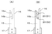
図1に示されるように、インプラント支持台7上にはインプラント・スタンド15が基台17によって固定されている。図2に示されるように、このインプラント・スタンド15は、上方に開口するように二股状の挟持体16が設けられている。この二股状の挟持体16には、幅の異なる複数の、この実施例では2つの、挟持部16a,16bが形成されている。
このインプラント・スタンド15には、図1に示されるように、インプラント10が挟持されて水平状態に支持される。
このインプラント・スタンド15には、図1に示されるように、インプラント10が挟持されて水平状態に支持される。
ここで、インプラントの標準的な施術手順を図4、5に基づいて説明すると以下のようである。
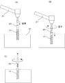
図4(A)(B)に示すように、インプラント10には、インプラントマウント20と呼ばれる固定手段が着脱可能に取り付けられる。このインプラントマウント20は、その表面に刻設された雄ネジを、インプラント10に形成された雌ネジ内にねじ込んで固定する。
次いで、図5に示すように、インプラントマウント20が装着されたインプラント10を、顎骨30に予め形成された埋入孔内に挿入する(A)。このインプラント10に取り付けられたインプラントマウント20に、インプラント10を回動するための歯科用ハンドピース21を係合する。歯科用ハンドピース21によってインプラントマウント20を回動してインプラント10を顎骨30内にねじ込み固定する(B)。
図4(A)(B)に示すように、インプラント10には、インプラントマウント20と呼ばれる固定手段が着脱可能に取り付けられる。このインプラントマウント20は、その表面に刻設された雄ネジを、インプラント10に形成された雌ネジ内にねじ込んで固定する。
次いで、図5に示すように、インプラントマウント20が装着されたインプラント10を、顎骨30に予め形成された埋入孔内に挿入する(A)。このインプラント10に取り付けられたインプラントマウント20に、インプラント10を回動するための歯科用ハンドピース21を係合する。歯科用ハンドピース21によってインプラントマウント20を回動してインプラント10を顎骨30内にねじ込み固定する(B)。
その後、歯科用ハンドピース21を取り外し、次いで、インプラントマウント20を逆回転してインプラント10から取り外す(C)。
その後に、クラウン(歯科用補綴物)が装着された歯科用アバットメントをインプラント10に取り付けるものである。
その後に、クラウン(歯科用補綴物)が装着された歯科用アバットメントをインプラント10に取り付けるものである。
しかして、本発明のインプラント用紫外線照射装置によって紫外線処理される対象物は、図4に示されたインプラント10にインプラントマウント20が取り付けられたものである。図1および図2に示すように、インプラント10を水平状態として、このインプラントマウント20を、インプラント・スタンド15の挟持体16に、開放された上方から挿入して支持するものである。これによって、図1に示すように、インプラント10は有効照射領域X内において紫外線ランプの管軸方向(長手方向)に沿うように水平状態で支持されることになる。
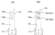
なお、挟持体16には複数の幅の異なる挟持部16a,16bが形成されているので、太さ(D1,D2)の異なるインプラントマウント20に対応できる。
なお、挟持体16には複数の幅の異なる挟持部16a,16bが形成されているので、太さ(D1,D2)の異なるインプラントマウント20に対応できる。
上記において、インプラント・スタンド15に支持されるインプラントマウント20は、挟持される部分を含めて、必ずしも全体が有効照射領域X内において紫外線照射処理されるわけではないが、前述したように、インプラント10が骨内に埋め込まれた後に取り外されるので、特に問題となることはなく、骨内に埋め込まれるインプラント10が、全領域(全長)において有効照射領域X内に配置されて紫外線処理されることが重要である。
図3(A)(B)にはインプラント・スタンド15の挟持体16の他の実施例が示されていて、この場合、二股状の挟持体15には上方に向けて漸次広がる挟持部16a,16bが形成されていて、太さの異なる複数のインプラントマウント20に対応できるようにされている。
なお、上記説明において、インプラント保持体は、開閉扉と一体のキャリッジによって筐体内に搬送する構造の従来例に則して説明したが、インプラント保持体の筐体への搬送はこれに限られず、手動によって直接筐体内に搬入して紫外線ランプに対向配置させる構造であってもよい。その場合、筐体の前面あるいは上面に開閉扉を設け、該開閉扉を開閉してインプラント保持体を搬入・搬出すればよい。また、筐体内にインプラント支持体のための位置決め手段を設けておくことが好ましい。
このような構造は装置が小型の場合などに特に有効である。
このような構造は装置が小型の場合などに特に有効である。
以上説明したように、本発明のインプラント用紫外線照射装置においては、インプラント保持体が、インプラント・スタンドを有し、該インプラント・スタンドは、前記インプラントに着脱自在に取り付けられたインプラントマウントの一端を支持して、前記インプラントを紫外線ランプの管軸方向(長手方向)に沿うように水平方向の姿勢で、前記紫外線ランプからの照射紫外線の有効照射領域内に維持するので、インプラントマウントによってインプラント・スタンドに支持されたインプラントは、その全領域が有効に紫外線照射処理される。
また、紫外線ランプに対応して横長に形成される有効照射領域に対して、インプラントが水平状態で支持されるので、当該インプラントを有効照射領域内に位置付けるための調整代にゆとりがあり、インプラントの全領域を的確に有効照射領域内に位置付けることができる。
また、インプラント・スタンドに二股状の挟持体を設けて、インプラントマウントをその開放上部から挿入するという簡単な操作で水平状態に支持することができる。
また、紫外線ランプに対応して横長に形成される有効照射領域に対して、インプラントが水平状態で支持されるので、当該インプラントを有効照射領域内に位置付けるための調整代にゆとりがあり、インプラントの全領域を的確に有効照射領域内に位置付けることができる。
また、インプラント・スタンドに二股状の挟持体を設けて、インプラントマウントをその開放上部から挿入するという簡単な操作で水平状態に支持することができる。
1 筐体
2 開閉扉
3 紫外線ランプ
4 キャリッジ
5 インプラント保持体
6 載置台
7 インプラント支持台
8 把手
8a 握り部
10 インプラント
15 インプラント・スタンド
16 挟持体
16a,16b 挟持部
17 基台
20 インプラントマウント
21 歯科用ハンドピース
30 顎骨
X 有効照射領域
Xa 有効照射領域の水平方向の範囲(長さ)
Xb 有効照射領域の垂直方向の範囲(長さ)
2 開閉扉
3 紫外線ランプ
4 キャリッジ
5 インプラント保持体
6 載置台
7 インプラント支持台
8 把手
8a 握り部
10 インプラント
15 インプラント・スタンド
16 挟持体
16a,16b 挟持部
17 基台
20 インプラントマウント
21 歯科用ハンドピース
30 顎骨
X 有効照射領域
Xa 有効照射領域の水平方向の範囲(長さ)
Xb 有効照射領域の垂直方向の範囲(長さ)
Claims (3)
- 筐体内に配設された紫外線ランプと、該筐体内の紫外線ランプと対向配置される搬送可能なインプラント保持体とからなり、紫外線によりインプラントの有機汚染物除去を行うためのインプラント用紫外線照射装置において、
前記インプラント保持体は、インプラント・スタンドを有し、該インプラント・スタンドは、前記インプラントに着脱自在に取り付けられたインプラントマウントの一端を支持して前記インプラントを水平方向の姿勢で、前記紫外線ランプからの照射紫外線の有効照射領域内に維持するものであることを特徴とするインプラント用紫外線照射装置。 - 前記インプラント・スタンドは、前記インプラント保持体に立設されて、上方に開口する二股状の挟持体を有することを特徴とする請求項1に記載のインプラント用紫外線照射装置。
- 前記挟持体は、前記インプラントマウントの太さに対応した複数の挟持部を有することを特徴とする請求項2に記載のインプラント用紫外線照射装置。
Applications Claiming Priority (2)
| Application Number | Priority Date | Filing Date | Title |
|---|---|---|---|
| JP2015-094996 | 2015-05-07 | ||
| JP2015094996A JP6098663B2 (ja) | 2015-05-07 | 2015-05-07 | インプラント用紫外線照射装置 |
Publications (1)
| Publication Number | Publication Date |
|---|---|
| WO2016178330A1 true WO2016178330A1 (ja) | 2016-11-10 |
Family
ID=57217973
Family Applications (1)
| Application Number | Title | Priority Date | Filing Date |
|---|---|---|---|
| PCT/JP2016/053495 Ceased WO2016178330A1 (ja) | 2015-05-07 | 2016-02-05 | インプラント用紫外線照射装置 |
Country Status (2)
| Country | Link |
|---|---|
| JP (1) | JP6098663B2 (ja) |
| WO (1) | WO2016178330A1 (ja) |
Families Citing this family (1)
| Publication number | Priority date | Publication date | Assignee | Title |
|---|---|---|---|---|
| KR102193851B1 (ko) * | 2019-06-21 | 2020-12-22 | 주식회사 디오 | 어버트먼트 지그 |
Citations (4)
| Publication number | Priority date | Publication date | Assignee | Title |
|---|---|---|---|---|
| JPH06154300A (ja) * | 1992-11-20 | 1994-06-03 | Takara Belmont Co Ltd | 移動用殺菌装置 |
| JP2008264294A (ja) * | 2007-04-23 | 2008-11-06 | Gc Corp | フィクスチャー用収納容器 |
| JP2009006143A (ja) * | 2007-06-25 | 2009-01-15 | Aesculap Ag | 外科容器用外科ホルダ及び外科容器 |
| JP2012000118A (ja) * | 2010-06-14 | 2012-01-05 | Ushio Inc | 人工歯根の有機汚染物除去装置 |
Family Cites Families (1)
| Publication number | Priority date | Publication date | Assignee | Title |
|---|---|---|---|---|
| JP3602816B2 (ja) * | 2001-10-11 | 2004-12-15 | プログレックス株式会社 | 医療用具の消毒器の補助具 |
-
2015
- 2015-05-07 JP JP2015094996A patent/JP6098663B2/ja not_active Expired - Fee Related
-
2016
- 2016-02-05 WO PCT/JP2016/053495 patent/WO2016178330A1/ja not_active Ceased
Patent Citations (4)
| Publication number | Priority date | Publication date | Assignee | Title |
|---|---|---|---|---|
| JPH06154300A (ja) * | 1992-11-20 | 1994-06-03 | Takara Belmont Co Ltd | 移動用殺菌装置 |
| JP2008264294A (ja) * | 2007-04-23 | 2008-11-06 | Gc Corp | フィクスチャー用収納容器 |
| JP2009006143A (ja) * | 2007-06-25 | 2009-01-15 | Aesculap Ag | 外科容器用外科ホルダ及び外科容器 |
| JP2012000118A (ja) * | 2010-06-14 | 2012-01-05 | Ushio Inc | 人工歯根の有機汚染物除去装置 |
Also Published As
| Publication number | Publication date |
|---|---|
| JP6098663B2 (ja) | 2017-03-22 |
| JP2016209244A (ja) | 2016-12-15 |
Similar Documents
| Publication | Publication Date | Title |
|---|---|---|
| JP5585473B2 (ja) | インプラント用紫外線照射装置 | |
| US8912507B2 (en) | Light irradiation device for dental implants | |
| KR20180015054A (ko) | 임플란트 처리 장치 | |
| JPWO2016143829A1 (ja) | 紫外線処理装置及びそのための遮光部品 | |
| JP6098663B2 (ja) | インプラント用紫外線照射装置 | |
| JP6048915B2 (ja) | インプラント用紫外線照射装置 | |
| KR20180015053A (ko) | 임플란트 처리 장치 | |
| KR20170015583A (ko) | 자외선을 이용한 기자재 살균장치 | |
| JP5838566B2 (ja) | インプラント用紫外線照射装置 | |
| RU140768U1 (ru) | Устройство для дезинфекции и стерилизации объектов | |
| DE10219431A1 (de) | Transportabler Einsatz und Verfahren | |
| KR102590340B1 (ko) | 임플란트의 표면처리용 자외선 조사장치 | |
| JP2012000118A (ja) | 人工歯根の有機汚染物除去装置 | |
| JP2016159176A (ja) | インプラント用紫外線照射装置 | |
| JP2012000120A (ja) | 人工歯根の有機汚染物除去装置 | |
| KR102404234B1 (ko) | 임플란트용 자외선 살균장치 | |
| TWI738264B (zh) | 醫用金屬的表面處理裝置 | |
| CN204890194U (zh) | 一种便携式医疗箱 | |
| CN115381973A (zh) | 一种紫外消毒装置及其制作方法 | |
| JP2012000119A (ja) | 人工歯根の有機汚染物除去装置 | |
| JP2003116969A (ja) | 医療用具の消毒器の補助具 | |
| RU86878U1 (ru) | Устройство для стерилизации медицинского инструмента и контейнер для медицинского инструмента | |
| US20160121008A1 (en) | Method and Apparatus for Rapid Sterilization of Hazmat Suits, Surgical Instruments and the Like | |
| KR20210003533A (ko) | 의료용 금속의 표면처리장치 | |
| CN221950267U (zh) | 一种房卡杀菌盒 |
Legal Events
| Date | Code | Title | Description |
|---|---|---|---|
| 121 | Ep: the epo has been informed by wipo that ep was designated in this application |
Ref document number: 16789466 Country of ref document: EP Kind code of ref document: A1 |
|
| NENP | Non-entry into the national phase |
Ref country code: DE |
|
| 122 | Ep: pct application non-entry in european phase |
Ref document number: 16789466 Country of ref document: EP Kind code of ref document: A1 |