WO2016170847A1 - 建設機械、建設機械用エンジンの換装方法及び建設機械の管理システム - Google Patents
建設機械、建設機械用エンジンの換装方法及び建設機械の管理システム Download PDFInfo
- Publication number
- WO2016170847A1 WO2016170847A1 PCT/JP2016/056074 JP2016056074W WO2016170847A1 WO 2016170847 A1 WO2016170847 A1 WO 2016170847A1 JP 2016056074 W JP2016056074 W JP 2016056074W WO 2016170847 A1 WO2016170847 A1 WO 2016170847A1
- Authority
- WO
- WIPO (PCT)
- Prior art keywords
- engine
- construction machine
- specifications
- control unit
- engine head
- Prior art date
- Legal status (The legal status is an assumption and is not a legal conclusion. Google has not performed a legal analysis and makes no representation as to the accuracy of the status listed.)
- Ceased
Links
Images



Classifications
-
- E—FIXED CONSTRUCTIONS
- E02—HYDRAULIC ENGINEERING; FOUNDATIONS; SOIL SHIFTING
- E02F—DREDGING; SOIL-SHIFTING
- E02F9/00—Component parts of dredgers or soil-shifting machines, not restricted to one of the kinds covered by groups E02F3/00 - E02F7/00
-
- E—FIXED CONSTRUCTIONS
- E02—HYDRAULIC ENGINEERING; FOUNDATIONS; SOIL SHIFTING
- E02F—DREDGING; SOIL-SHIFTING
- E02F9/00—Component parts of dredgers or soil-shifting machines, not restricted to one of the kinds covered by groups E02F3/00 - E02F7/00
- E02F9/20—Drives; Control devices
Definitions
- the present invention relates to a configuration of an engine in a construction machine, and relates to a construction machine including the engine, a method for replacing the engine for the construction machine, and a management system for managing the construction machine.
- Diesel engines are mainly used as prime movers for hydraulic excavators, but the engine specifications vary depending on the region and country where they are sold. Major factors that determine engine specifications include the level of emission regulations and the quality level of fuel in the country of sale, and the type of fuel injection device and the presence or absence of an exhaust gas aftertreatment device are determined accordingly.
- a mechanical injector has been used for a long time in a fuel supply device of a diesel engine, it is becoming difficult to meet the standards as exhaust gas regulations become stricter.
- the mechanical injector has advantages such as high robustness against poor fuel because of its simple structure. Therefore, an engine equipped with a mechanical injector is suitable as an engine for an emerging country where the emission control level is relatively gradual and fuel quality control is not sufficient.
- Patent Document 1 discloses a technique related to a method for controlling an exhaust gas aftertreatment device (urea SCR) in developed and emerging countries.
- the controller determines that the vehicle body is in the exhaust gas non-regulated area based on the position information detected by the GPS device, and the urea water injection control is deactivated. And normal operation of the engine and hydraulic system and no monitor warning (see summary).
- the specifications of construction machinery diesel engines vary depending on the region and country where they are sold.
- a diesel engine for construction machinery for emerging countries a highly robust engine (for example, a mechanical injector engine) is selected.
- a low exhaust gas specification engine for example, a common rail fuel injection device + cooled EGR + exhaust gas aftertreatment device is selected. That is, since it is necessary to prepare a plurality of types of engines depending on the destination, there is a problem that the manufacturing cost of the construction machine increases.
- the present invention has an object to optimize the construction of a construction machine engine in consideration of the destination correspondence and reduce the manufacturing cost of construction equipment sold globally.
- a construction machine is a construction machine including an engine, wherein the engine includes a plurality of specification engine head portions in which members that need to be attached / detached or replaced for each of a plurality of specifications are collectively arranged.
- An engine head portion selected from among the engine head portions, and an engine block portion common to the engine head portions of the plurality of specifications.
- a method for replacing an engine mounted on a construction machine is directed to a plurality of engine head portions in which members that need to be attached / detached or replaced for each of a plurality of specifications are collectively arranged.
- a method for replacing an engine for a construction machine wherein an engine head portion having specifications according to the ground is selected and the engine head portion is mounted on a common engine block portion on which the plurality of specification engine head portions can be mounted.
- a management system for managing a construction machine includes a center server for managing the construction machine, and the center server determines the position and specification information of the individual from the individual of the construction machine. And the environment information used by the individual, determine whether the individual is permitted to start or not based on the position and specification information, and the environmental information, and remotely manage the individual based on the determination .
- the engine head corresponding to the destination can be attached to the shared engine block without preparing multiple engines.
- the manufacturing cost can be reduced.
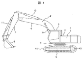
- FIG. 1 is an external view of a hydraulic excavator according to Embodiment 1.
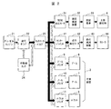
- FIG. 1 is a diagram illustrating a system configuration of a hydraulic excavator according to Embodiment 1.
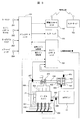
- FIG. 1 is a diagram illustrating a system configuration around an engine of a hydraulic excavator according to Embodiment 1.
- the figure which shows the basic policy of the destination correspondence of this invention in a new vehicle in the case of a hydraulic excavator.
- FIG. 1 The figure which shows the solution of the subject regarding the engine design for the destination correspondence in the construction machine of a new vehicle.
- the figure which shows the subject at the time of export correspondence of a used machine (in the case of a hydraulic excavator).
- FIG. The figure which shows the subject regarding the control unit at the time of export correspondence of a used machine The figure which shows the solution of the subject regarding the control unit at the time of export correspondence of a used machine based on Example 2.
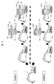
- FIG. The figure which shows the separate management system regarding the engine specification by the center server based on Example 2.
- the present invention can be applied to a construction machine including an engine (internal combustion engine) such as a hydraulic excavator, a dump truck, and a wheel loader.
- an engine internal combustion engine
- a hydraulic excavator will be described as an example of a construction machine.
- symbol is attached
- FIG. 1 is a diagram illustrating an appearance of a hydraulic excavator according to the present embodiment.
- the hydraulic excavator 1 includes an articulated work device 2 including a boom 6, an arm 7, and a bucket 8 that rotate in a vertical direction, and a vehicle body 3 including an upper swing body 4 and a lower traveling body 5.
- the base end of the boom 6 of the device 2 is supported on the front portion of the upper swing body 4 so as to be rotatable with respect to the vertical direction.
- FIG. 2 is a diagram illustrating a system configuration of the hydraulic excavator according to the present embodiment.
- the diesel engine 21 and the hydraulic pump 22 are mechanically connected, and the hydraulic pump 22 is driven by the engine 21.
- the hydraulic oil sent from the hydraulic oil tank 24 is compressed into pressure oil and sent to the control valve 23.
- the control valve 23 has a function of distributing the pressure oil necessary for the traveling operation, the upper swinging body operation, and the work device operation based on an operation command from the operator, and returning unnecessary pressure oil to the hydraulic oil tank 24.
- the swing hydraulic motor 31 uses the pressure oil distributed from the control valve 23 as a power source, and drives the upper swing body 4 via the swing reduction device 32 and the swing gear (swivel wheel) 33.
- the crawler 44 is driven via the traveling speed reduction device 43 using the pressure oil sent from the control valve 23 via the center joint 41.
- the boom cylinder 9, the arm cylinder 10, and the bucket cylinder 11 are driven based on the pressure oil distributed from the control valve 23, and the boom 6,
- the arm 7 and the bucket 8 are controlled to a desired movement.
- FIG. 3 is a diagram illustrating a system configuration around the engine of the hydraulic excavator according to the present embodiment.
- the diesel engine 21 is directly connected to the hydraulic pump 22 via an output shaft 305 as a power source for driving the hydraulic pump 22, and the diesel engine 212 is controlled by the engine control unit 104.
- control units there are a main control unit 101 that controls the center of the hydraulic excavator 1, a monitor unit 103 that provides an operator with information on hydraulic pressure and an engine, and an information control unit 102 that exchanges excavator information with the outside. These units are connected to each other by an information network.
- the information control unit 102 can communicate with the center server 105 through satellite communication. In addition to transmitting the excavator individual information to the center server 105, the information control unit 102 transmits the infrastructure information transmitted from the center server 105 and the individual information. Receives reference information and command values.
- a key switch 201 related to engine start and stop As inputs to the main control unit 101 related to engine control, a key switch 201 related to engine start and stop, an engine control dial 202 for designating the engine speed, an auto idle switch 203 for optimizing the idle speed, the engine There is a power mode switch 204 or the like for adjusting the output.
- the main control unit 101 calculates a target engine speed based on these pieces of information and transmits it to the engine control unit 104.
- the engine control unit 104 instructs the fuel injection device 301 on the target fuel injection amount based on the difference between the target engine speed transmitted from the main control unit 101 and the actual engine speed detected by the rotation sensor 306. , Control the engine speed.
- the diesel engine 21 includes an electronically controlled fuel injection device 301, a turbocharger 303, a supercharging pressure sensor 307, a crankcase pressure sensor 308, and a DPF (Diesel Particulate Filter) device 401 which is a kind of exhaust gas purification device. ing.
- the DPF device 401 is installed in the exhaust pipe 304, and includes an oxidation catalyst 402 disposed on the upstream side and a PM collection filter 403 disposed on the downstream side. Further, the DPF device 401 is provided with an exhaust temperature sensor 404 and a DPF differential pressure sensor.
- the filter 403 collects particulate matter contained in the exhaust gas. Output signals of the supercharging pressure sensor 307, the crankcase pressure sensor 308, the exhaust temperature sensor 404, and the DPF differential pressure sensor are input to the engine control unit 104.
- the diesel engine 21 has a plurality of cylinders, an intake manifold 310 that distributes the air sent from the intake pipe 309 to each cylinder, and an exhaust that collects exhaust discharged from each cylinder and sends it to the exhaust pipe 304.
- a manifold 302 is assembled.
- the turbocharger 303 is provided between the exhaust manifold 302 and the intake pipe 309.
- the supercharging pressure sensor 307 is provided in the intake pipe 309.
- FIG. 4 is a diagram illustrating a problem when dealing with a destination in a new vehicle (in the case of a hydraulic excavator).
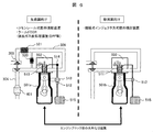
- FIG. 5 is a diagram showing a basic policy for dealing with a destination according to the present invention in a new vehicle (in the case of a hydraulic excavator).
- the low exhaust gas specification engine 701 includes, for example, a common rail fuel injection device 301A + cooled EGR520 + exhaust gas aftertreatment device (for example, a DPF device 401).
- EGR exhaust Gas Recirculation
- a cooled EGR having a cooling mechanism by a heat exchanger is adopted, but a normal EGR having no cooling mechanism may be used.
- the EGR is composed of an EGR valve and a pipe connecting the exhaust pipe and the intake pipe.
- a cooling mechanism using a heat exchanger is further provided.
- Reference numeral 520 particularly represents an EGR valve and a cooling mechanism using a heat exchanger.
- a highly robust engine 702 is selected in consideration of a relatively gradual emission control level and a quality level of fuel that is not sufficiently managed.
- the high robustness engine 702 is constituted by, for example, a mechanical injector type engine provided with a fuel injection device 301B using a mechanical injector.
- the engine block unit 501 is common regardless of the destination, and only the engine heads 502a and 502b are made compatible with the destination. Thereby, the destination correspondence of the engine for the hydraulic excavator is completed only by replacing the engine head portions 502a and 502b. As a result, it is not necessary to prepare a plurality of types of engines, man-hours for manufacturing and mounting can be reduced, and the manufacturing cost of the excavator can be reduced.
- FIG. 6 is a diagram illustrating a problem related to engine design for dealing with a destination in a construction machine for a new vehicle.
- the exhaust gas reduction device includes a common rail fuel injection device 301A, a cooled EGR 520, an exhaust gas aftertreatment device [DPF 401], and the like.
- the engine for developed countries includes a common rail 514, and the engine head unit 502 is provided with a common rail compatible injector 510. Further, a fuel feed pump 512 and a common rail supply pump 513 are provided in an engine block portion 501a of an engine for developed countries.
- the common rail supply pump 513 is a device that boosts the low-pressure fuel sent from the fuel tank 515 by the fuel feed pump 512 and sends it to the common rail 514.
- an engine for an advanced country may be provided with an intercooler 521 in the intake pipe 309.
- the engine for emerging countries has a simple configuration such as adopting a mechanical injector type fuel injection device (row type, distribution type, unit injector) 310B in consideration of local fuel quality and maintenance environment.
- the engine for emerging countries includes a mechanical injector (unit injector) 511 in the engine head portion 503.
- the common rail supply pump 513 is not necessary, and only the fuel feed pump 512 is provided in the engine block portion 501b.
- the engine block unit 501 is shared between the engine for developed countries and the engine for emerging countries from the design stage, and by designing each engine, the engine head unit 502a with both specifications is bolt-on. 502b can be replaced.
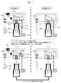
- FIG. 7 is a diagram illustrating a solution to a problem related to engine design for a destination corresponding to a construction machine for a new vehicle.
- auxiliary equipment to be mounted on the engine block unit 501 is only the auxiliary equipment that is common to both specifications, and individual exhaust gas reduction members (fuel injection devices 301A and 301B, EGR valve 520, turbocharger 303, after exhaust The processing device [DPF 401] or the like) performs a centralized arrangement on the engine head units 502a and 502b.
- a fuel feed pump 512 and a common rail supply pump 513 as related auxiliary machines. These auxiliary machines were originally mounted on the engine block unit 501. However, since these components have different components and specifications between the engine for developed countries and the engine for emerging countries, the engine head units 502a and 502b are used. It is concentrated on the side. That is, in the engine for developed countries, the fuel feed pump 512 and the common rail supply pump 513 are centrally arranged in the engine head portion 502a. In the engine for emerging countries, the fuel feed pump 512 is disposed in the engine head portion 502b.
- the engine system for the construction machine has a plurality of engine head portions 502a and 502b in which members that need to be attached / detached or replaced in accordance with different levels of exhaust gas regulations or fuel properties are collectively arranged. And a common engine block unit 501 on which engine head units 502a and 502b having a plurality of specifications can be mounted.
- the engine heads 502a and 502b having specifications according to the destinations are selected and mounted on the engine block unit 501, so that the necessary members are engine for each destination according to the selection of the engine heads 502a and 502b.
- the engine head units 502a and 502b having a plurality of specifications and the engine block unit 501 used in common for the engine head units 502a and 502b having a plurality of specifications are provided.
- a system in which the engine head portions 502a and 502b can be replaced is called a construction machine engine system.
- the plurality of specifications are specifications corresponding to different levels of exhaust gas regulations or fuel properties.
- the plurality of specifications may be set from a viewpoint other than exhaust gas regulations or fuel properties.
- the second example relates to the export of used machines in construction machinery, and assumes a case where a hydraulic excavator used in developed countries is sold as a used machine to emerging countries.
- the specifications of hydraulic excavator engines may be changed in consideration of operational conditions in emerging countries.
- the common rail fuel injection device 301A which is common in developed countries, will break down. Therefore, it is necessary to change the fuel injection device 301A.
- FIG. 8 is a diagram showing a problem when exporting a used machine (in the case of a hydraulic excavator).
- a used machine in the case of a hydraulic excavator.
- the low exhaust engine 700A is changed to a high robust engine 700B
- the low exhaust engine 700A of the common rail fuel injection device 301A is entirely replaced with a high robust engine 700B of a mechanical injector system 310B.
- FIG. 9 is a diagram illustrating a basic policy when second-hand machines are exported according to the present embodiment.
- the engine configuration in the first embodiment is followed. Therefore, as shown in FIG. 9, when selling a hydraulic excavator used in developed countries as a second-hand machine for emerging countries, the engine block unit 501 that is a common part is not changed, and the destination is not changed. By simply replacing the engine heads 502a and 502b with the required specifications, the export of used hydraulic excavator engines can be completed.
- the engine mount 710 does not need to be replaced. As a result, it is not necessary to prepare the old specification engine (highly robust engine) 700B and the like, the number of man-hours for replacement can be reduced, and the export cost can be reduced.
- FIG. 10 is a diagram illustrating a problem related to the control unit when second-hand machines are exported.
- the engine head unit 502a, 502b is replaced and the common rail type engine 700A is changed to the mechanical injector type engine 700B.
- the common rail engine ECU 104A it is necessary to replace the common rail engine ECU 104A with the mechanical injector engine ECU 104B.
- the mechanical injector type engine 700B has a simpler configuration than the common rail type engine 700A. For this reason, the number of devices and sensors to be mounted, engine control items, and diagnosis contents are inevitably reduced as compared with the common rail engine 700A.
- the common rail engine control program 603 executed by the common rail engine 700A and the mechanical injector engine control program 604 executed by the mechanical injector engine 700B are different. Further, the common rail type engine control support program 601 corresponding to the common rail type engine control program 603 does not normally correspond to the mechanical injector type engine control program 604.
- the amount of information transmitted and received is reduced by exchanging the mechanical injector type engine 700B and its control ECU 104B, which is implemented between the main control unit 101 that controls the entire hydraulic excavator and the common rail type engine control unit 104A.
- the problem of inconsistent exchange of information occurs. Specifically, when the main control unit 101 side requests common rail-related or DPF-related information from the engine control 104B side, a calculation error occurs due to the absence of a response, and the hydraulic excavator 1 operates normally. It becomes a result that cannot be operated.
- FIG. 11 is a diagram illustrating a solution to the problem relating to the control unit when second-hand machines are supported for export according to the present embodiment.
- both control programs that are assumed when the common rail type engine 700A is installed and when the mechanical injector type engine 700A is installed are mounted in advance.
- a “common rail type engine control support program 601” and a “mechanical injector type engine control support program 602” are written in the main control unit 101.
- the main control unit 101 is provided with a dip switch 610a, and the programs 601 and 602 can be switched from the outside by the dip switch 610a.
- the engine control unit 104 has a “common rail engine control program 603” and a “mechanical injector engine control program 604” written therein.
- the engine control unit 104 is provided with a dip switch 610b, and the programs 603 and 604 can be switched from the outside by the dip switch 610b.
- control of multiple specifications corresponding to multiple engine heads according to the destination Install the program in advance. Then, when selecting the engine head unit corresponding to the destination, the control program executed in the engine control unit 104 and other control units (main control unit 101 etc.) communicating with the engine control unit 104 accordingly. Change the contents. As a result, it is possible to prevent errors and the like due to inconsistencies in the information amount without unnecessarily increasing the types of control units.
- switching of the control contents by the DIP switches 610a and 610b has been described.
- the present invention is not limited to this, and a method of automatically switching when the control units 101 and 104 detect inconsistency may be used. good.
- a method of mounting a plurality of programs in the control units 101 and 104 in advance has been described.
- the present invention is not limited to this, and a plurality of programs are mounted on a maintenance tool or the like. Accordingly, a program may be transferred from the maintenance tool to the control units 101 and 104 to rewrite the programs in the control units 101 and 104.
- FIG. 12 is a diagram illustrating an individual management system related to engine specifications by the center server according to the present embodiment.
- the center server 105 connects each individual excavator 1 via an information network.
- the center server 105 selects each individual of the excavator 1 based on various information collected from each individual of the excavator 1 (individual position / specification information of the construction machine, exhaust gas regulation area information IV, fuel property area information, etc.). Remote management.
- individual position / specification information of the construction machine exhaust gas regulation area information IV, fuel property area information, etc.
- Remote management if there is a mismatch between the engine specifications of the excavator 1 and the contents of exhaust gas regulations and fuel properties in the area where the excavator 1 is located, “do not allow the excavator 1 to start” or Take measures such as “Allow activation with alert”.
- the individual construction machine based on the individual position / specification information 1201 of the construction machine, the exhaust gas regulation area information 1202, the fuel property area information 1203, and the like. It is possible to prevent unauthorized modification and failure of the hydraulic excavator by determining whether the activation is permitted or not and remotely managing the individual construction machine according to the above determination.
- the individual position / specification information 1201 of the construction machine, the exhaust gas regulation area information 1202, the fuel property area information 1203, and the like are environmental information regarding the environment in which the individual construction machine is used.
- the specifications of the construction machine engine are determined so as to match this environmental information.
- the specifications of the construction machine engine may be determined based on environmental information other than the above.
- the management system of the present embodiment it is possible to optimize the configuration of the construction machine engine in consideration of the destination correspondence, reduce the manufacturing cost of construction machinery sold globally, and the state according to the destination Thus, the engines 700A and 700B of the construction machine can be operated.
- this invention is not limited to each above-mentioned Example, Various modifications are included.
- the above-described embodiments have been described in detail for easy understanding of the present invention, and are not necessarily limited to those having all the configurations.
- a part of the configuration of one embodiment can be replaced with the configuration of another embodiment, and the configuration of another embodiment can be added to the configuration of one embodiment.
Landscapes
- Engineering & Computer Science (AREA)
- Mining & Mineral Resources (AREA)
- Civil Engineering (AREA)
- General Engineering & Computer Science (AREA)
- Structural Engineering (AREA)
- Combined Controls Of Internal Combustion Engines (AREA)
- Operation Control Of Excavators (AREA)
- Component Parts Of Construction Machinery (AREA)
Abstract
油圧ショベル用ディーゼルエンジンの仕様は、販売する地域や国々によって異なり、仕向け地によって複数種のエンジンを準備する必要があるため、ショベルの製造コストが増加する課題があった。エンジンを備えた建設機械において、エンジンは、複数の仕様毎に着脱又は交換が必要な部材を集約配置した複数仕様のエンジンヘッド部502aの中から選択されたエンジンヘッド部502aと、複数仕様のエンジンヘッド部502aに共通のエンジンブロック部501とを有することを特徴とする建設機械。
Description
本発明は、建設機械におけるエンジンの構成に係り、このエンジンを備えた建設機械、建設機械用エンジンの換装方法及び建設機械を管理する管理システムに関する。
油圧ショベルの原動機には、主にディーゼルエンジンが用いられているが、そのエンジンの仕様は、販売する地域や国々によって異なる。エンジンの仕様を決定する大きな要因として、販売国における排出ガス規制のレベルや燃料の品質レベル等があり、それに応じて燃料噴射装置の形式や排出ガス後処理装置の有無等が決定される。
例えば、ディーゼルエンジンの燃料供給装置には、長らく機械式インジェクタが用いられてきたが、排出ガス規制が厳しくなるにつれて、その水準をクリアすることが困難になりつつある。その反面、機械式インジェクタは、そのシンプルな構造故に、粗悪燃料に対してロバスト性が高い等の利点を有する。よって、機械式インジェクタ搭載のエンジンは、排出ガス規制レベルが比較的緩やかで、燃料の品質管理が十分で無い新興国向けのエンジンとして適している。
一方で、先進国向けのディーゼルエンジンにおいては、高いレベルの排出ガス規制に対応するため、エンジンの燃料供給装置は、機械式インジェクタシステムからコモンレール式燃料噴射システムに取って代わられつつある。これに加えて、新鋭のディーゼルエンジンでは、クールドEGR装置、排出ガス後処理装置(DPFや尿素SCR)等の各種排出ガス対応デバイスが装着される。しかしながら、これら新鋭の規制対応デバイスは複雑且つ精密であり、その性能を維持・発揮するためには、高品質な燃料や油脂類、及び定期的なメンテナンスが必要となる。したがって、その運用は、インフラ環境の整った先進国に限定される課題を有する。
上記に関し、特開2009-127521号公報(特許文献1)では、先進国と新興国における、排出ガス後処理装置(尿素SCR)の制御方法に関する技術が開示されている。
特許文献1では、油圧ショベルが排ガス未規制地域に移送されると、コントローラはGPS装置により検出した位置情報に基づいて、車体が排ガス未規制地域にあると判定し、尿素水噴射制御を不作動とし、かつエンジン及び油圧システムを通常作動としモニタ警告を無しとする(要約参照)。
特許文献1では、油圧ショベルが排ガス未規制地域に移送されると、コントローラはGPS装置により検出した位置情報に基づいて、車体が排ガス未規制地域にあると判定し、尿素水噴射制御を不作動とし、かつエンジン及び油圧システムを通常作動としモニタ警告を無しとする(要約参照)。
前記の様に、油圧ショベルを含む建設機械用ディーゼルエンジンの仕様は、販売する地域や国々によって異なる。新興国向けの建設機械用ディーゼルエンジンについては、高ロバスト性エンジン(例えば、機械式インジェクタ装着エンジン)が選択される。先進国向けエンジンは、低排出ガス仕様エンジン(例えば、コモンレール式燃料噴射装置+クールドEGR+排出ガス後処理装置等)が選択される。すなわち、仕向け地によって複数種のエンジンを準備する必要があるため、建設機械の製造コストが増加する課題があった。
また、先進国にて使用した建設機械を、新興国向けに中古機として販売する際には、新興国における運用インフラを考慮して、建設機械の仕様を変更する場合がある。仕様の変更に際しては、特許文献1に記載される様に、DPFや尿素SCR等の排気後処理装置の動作を停止する、あるいは取り外すのみで対応可能なケースもある。しかし、先進国にて使用した建設機械を燃料の品質管理が不十分な国々に輸出する際には、ロバスト性に対する配慮が必要になる。例えば、先進国仕様では一般的なコモンレール式燃料噴射装置を備えた建設機械をそのまま燃料の品質管理が不十分な国々に輸出すると、コモンレール式燃料噴射装置が故障する恐れがある。そのため、仕向け地によっては、機械式インジェクタ方式の旧仕様エンジンに丸ごと換装する必要があり、転売コストが増加する課題があった。
本発明は、仕向け地対応を考慮して建設機械用エンジンの構成を最適化し、グローバルに販売する建設機械の製造コストを低減することを目的とする。
上記目的を達成するために、本発明の建設機械は、エンジンを備えた建設機械において、前記エンジンは、複数の仕様毎に着脱又は交換が必要な部材を集約配置した複数仕様のエンジンヘッド部の中から選択されたエンジンヘッド部と、前記複数仕様のエンジンヘッド部に共通のエンジンブロック部とを有する。
上記目的を達成するために、本発明の建設機械に搭載されるエンジンの換装方法は、複数の仕様毎に着脱又は交換が必要な部材を集約配置された複数仕様のエンジンヘッド部の中から仕向け地に応じた仕様のエンジンヘッド部を選択し、前記複数仕様のエンジンヘッド部を搭載可能な共通のエンジンブロック部に搭載してエンジンを換装することを特徴とする建設機械用エンジンの換装方法。
上記目的を達成するために、本発明の建設機械を管理する管理システムは、上記建設機械を管理するセンターサーバーを備え、前記センターサーバーは、前記建設機械の個体から、前記個体の位置及び仕様情報と前記個体が使用される環境情報とを取得し、前記位置及び仕様情報と前記環境情報とに基づいて前記個体の起動許可または不許可を判断し、前記判断に基づいて前記個体を遠隔管理する。
建設機械用エンジンの仕向け地対応に際し、複数種エンジンを準備することなく、共有化されたエンジンブロック部に、仕向け地に対応したエンジンヘッド部を取り付けられるようにすることで、仕向け地対応を容易にし、かつ製造コストを低減することが可能となる。
上記した以外の課題、構成及び効果は、以下の実施形態の説明により明らかにされる。
上記した以外の課題、構成及び効果は、以下の実施形態の説明により明らかにされる。
以下、本発明の一実施例について、図面を用いて説明する。本発明は、例えば油圧ショベル、ダンプトラック及びホイールローダなど、エンジン(内燃機関)を備えた建設機械に適用することができる。以下、建設機械の一例として、油圧ショベルについて説明する。なお、各図面において、共通する構成要素については同じ符号を付し、重複する説明を省略する。
図1を用いて本発明の一実施形態に係る油圧ショベル1について説明する。図1は、本実施例に係る油圧ショベルの外観を示す図である。
油圧ショベル1は、垂直方向にそれぞれ回動するブーム6、アーム7及びバケット8からなる多関節型の作業装置2と、上部旋回体4及び下部走行体5からなる車体3とで構成され、フロント装置2のブーム6の基端は、上部旋回体4の前部に、垂直方向に対して回動可能に支持されている。
次に、図2を用いて油圧ショベル1の全体システム構成を説明する。図2は、本実施例に係る油圧ショベルのシステム構成を示す図である。
ディーゼルエンジン21と油圧ポンプ22は機械的に接続されており、エンジン21によって油圧ポンプ22が駆動される。油圧ポンプ22では、作動油タンク24から送り込まれる作動油を圧縮して圧油とし、コントロールバルブ23に送り込む。コントロールバルブ23は、オペレータからの操作指令を基に、走行動作、上部旋回体動作、作業装置動作に必要な圧油を分配し、不要な圧油については作動油タンク24に戻す機能を有する。
旋回油圧モータ31は、コントロールバルブ23から分配された圧油を動力源にし、旋回減速装置32、旋回歯車(旋回輪)33を介して上部旋回体4を駆動する。走行油圧モータ42においては、センタージョイント41を経由してコントロールバルブ23から送られた圧油を用い、走行減速装置43を介してクローラ44を駆動する。また、作業装置2(ブーム6、アーム7、バケット8)については、コントロールバルブ23から分配された圧油を基に、ブームシリンダ9、アームシリンダ10、バケットシリンダ11を駆動し、それぞれブーム6、アーム7、バケット8を所望の動きに制御する。
次に、図3を用いて油圧ショベル1のエンジン周辺のシステム構成を説明する。図3は、本実施例に係る油圧ショベルのエンジン周辺のシステム構成を示す図である。
油圧ポンプ22には、油圧ポンプ22を駆動するための動力源として、出力シャフト305を介してディーゼルエンジン21が直結されており、ディーゼルエンジン212はエンジンコントロールユニット104によって制御される。その他のコントロールユニットとしては、油圧ショベル1の中枢を司るメインコントロールユニット101、オペレータに油圧やエンジンに関する情報を提供するモニターユニット103、ショベル情報に関して外部とやり取りを行う情報コントロールユニット102が存在する。これらのユニットは、情報ネットワークによって相互に接続されている。また、情報コントロールユニット102は、衛星通信を通じて、センターサーバー105と相互通信が可能であり、ショベルの個体情報をセンターサーバー105へ送信する他、センターサーバー105から発信されるインフラ情報や各個体への参考情報、指令値を受信する。
エンジン制御に関わるメインコントロールユニット101への入力としては、エンジンの始動や停止に関わるキースイッチ201、エンジンの回転数を指定するエンジンコントロールダイヤル202、アイドル回転数を最適化するオートアイドルスイッチ203、エンジンの出力を調整するパワーモードスイッチ204等がある。メインコントロールユニット101では、これらの情報を基に目標エンジン回転数を演算し、エンジンコントロールユニット104へ送信する。
エンジンコントロールユニット104では、メインコントロールユニット101から送信された目標エンジン回転数と、回転センサ306によって検出された実エンジン回転数の差分に基づいて、燃料噴射装置301に対し目標燃料噴射量を指示し、エンジン回転数を制御する。
また、ディーゼルエンジン21は、電子制御式の燃料噴射装置301、ターボチャージャー303、過給圧センサ307、クランクケース圧センサ308および排気ガス浄化装置の一種であるDPF(Diesel Particulate Filter)装置401を備えている。DPF装置401は排気管304に設置されており、上流側に配置された酸化触媒402と、その下流に配置されたPM捕集フィルタ403より構成される。また、DPF装置401には排気温度センサ404及びDPF差圧センサが設けられている。フィルタ403は排気ガスに含まれる粒子状物質を捕集する。過給圧センサ307、クランクケース圧センサ308、排気温度センサ404及びDPF差圧センサの各出力信号は、エンジンコントロールユニット104に入力される。
ディーゼルエンジン21は、複数の気筒を有しており、吸気管309から送られてくる空気を各気筒に配分する吸気マニホールド310と、各気筒から排出される排気を集めて排気管304に送り出す排気マニホールド302とが組み付けられている。ターボチャージャー303は排気マニホールド302と吸気管309との間に設けられている。また、過給圧センサ307は吸気管309に設けられている。
次に、本実施例における建設機械用エンジンの仕向け地対応の基本的な考え方を、図4および図5を用いて説明する。図4は、新車(油圧ショベルの場合)における仕向け地対応時の課題を示す図である。図5は、新車(油圧ショベルの場合)における本発明の仕向け地対応の基本方針を示す図である。
前述の様に、油圧ショベル用ディーゼルエンジンの仕様は、販売する地域や国々によって異なる。例えば、先進国向けエンジンは、高いレベルの排出ガス規制や良好な燃料の品質レベルを考慮して、低排出ガス仕様エンジン701が選択される。低排出ガス仕様エンジン701は、例えば、コモンレール式燃料噴射装置301A+クールドEGR520+排出ガス後処理装置(例えばDPF装置401)等で構成される。
EGR(Exhaust Gas Recirculation)は、排気ガスの一部を吸気側へ再循環させる技術(装置)である。本実施例では、熱交換器による冷却機構を持つクールドEGRを採用しているが、冷却機構を持たない通常のEGRであってもよい。EGRは、EGRバルブと、排気管と吸気管とを接続する配管とで、構成される。クールドEGRの場合は、さらに熱交換器による冷却機構を備える。符号520は、特にEGRバルブと熱交換器による冷却機構とを表す。
一方、新興国向けのショベル用ディーゼルエンジンについては、比較的緩やかな排出ガス規制レベルや管理が十分に行き届いていない燃料の品質レベルを考慮して、高ロバスト性エンジン702が選択される。高ロバスト性エンジン702は、例えば、機械式インジェクタによる燃料噴射装置301Bを備えた機械式インジェクタ方式エンジンで構成される。
図4に示す様に、従来は、これらの仕様のエンジンを別々に準備し、仕向け地毎に選択して油圧ショベル1に搭載していた。このため、従来の考え方では、製造コストが増加する課題があった。
本実施例によれば、図5に示す様に、エンジンブロック部501については仕向け地に関わらず共通とし、エンジンヘッド部502a,502bのみを仕向け地対応とする。これにより、エンジンヘッド部502a,502bの載せ替えのみで、油圧ショベル用エンジンの仕向け地対応が完了する。これによって、複数種のエンジンを準備する必要が無く、製造や実装の工数を削減でき、ショベルの製造コストを低減できる。
次に、エンジンブロック部501を共通化するための課題を、図6を用いて説明する。
図6は、新車の建設機械における仕向け地対応のためのエンジン設計に関する課題を示す図である。
図6は、新車の建設機械における仕向け地対応のためのエンジン設計に関する課題を示す図である。
先進国向けのエンジンは、高いレベルの排出ガス規制をクリアするため、種々の排出ガス低減装置が装着されている。排出ガス低減装置は、コモンレール式燃料噴射装置301A、クールドEGR520、排出ガス後処理装置[DPF401]等で構成される。また、先進国向けのエンジンはコモンレール514を備え、エンジンヘッド部502にはコモンレール対応インジェクタ510が設けられている。さらに先進国向けのエンジンのエンジンブロック部501aには、燃料フィードポンプ512及びコモンレール用サプライポンプ513が設けられている。コモンレール用サプライポンプ513は、燃料フィードポンプ512により燃料タンク515から送られてくる低圧燃料を昇圧してコモンレール514に送る装置である。その他に先進国向けのエンジンには、吸気管309にインタークーラー521が設けられる場合もある。
一方、新興国向けのエンジンは、現地における燃料の質やメンテナンス環境を考慮し、機械式インジェクタ型燃料噴射装置(列型、分配型、ユニットインジェクタ)310Bを採用する等のシンプルな構成としている。新興国向けのエンジンは、エンジンヘッド部503に機械式インジェクタ(ユニットインジェクタ)511を備える。また、新興国向けのエンジンの場合、コモンレール用サプライポンプ513は必要なく、エンジンブロック部501bには燃料フィードポンプ512のみが設けられている。
これらのエンジンを独立に設計した場合、以下の理由等により、エンジンブロック部501の共有化は困難である。
・ボアピッチ、ヘッドボルト穴、水穴等が異なる。
・エンジンブロック部501へ取り付ける補機の種類や取り付け位置が統一されていない。
・ボアピッチ、ヘッドボルト穴、水穴等が異なる。
・エンジンブロック部501へ取り付ける補機の種類や取り付け位置が統一されていない。
そこで本実施例においては、設計段階から先進国向けエンジンと新興国向けエンジンにおけるエンジンブロック部501の共有化を前提とし、それぞれのエンジンを設計することで、ボルトオンで両仕様のエンジンヘッド部502a,502bを換装可能としている。
具体的は、図7に示す様に、以下の事項を実施する。図7は、新車の建設機械における仕向け地対応のためのエンジン設計に関する課題の解決策を示す図である。
・ボアピッチ、ヘッドボルト穴、水穴等の共通化。
・エンジンブロック部501へ装着する補機類は、両仕様で共通の補機類のみとし、個別の排出ガス低減に関わる部材(燃料噴射装置301A,301B、EGRバルブ520、ターボチャージャー303、排気後処理装置[DPF401]等)はエンジンヘッド部502a,502bへ集約配置を実施する。
・ボアピッチ、ヘッドボルト穴、水穴等の共通化。
・エンジンブロック部501へ装着する補機類は、両仕様で共通の補機類のみとし、個別の排出ガス低減に関わる部材(燃料噴射装置301A,301B、EGRバルブ520、ターボチャージャー303、排気後処理装置[DPF401]等)はエンジンヘッド部502a,502bへ集約配置を実施する。
本実施例の場合、関連する補機として燃料フィードポンプ512やコモンレール用サプライポンプ513がある。これらの補機は、元来はエンジンブロック部501に装着されていたが、これらは先進国向けエンジンと新興国向けエンジンとの間で部材の有無や仕様が異なるため、エンジンヘッド部502a,502b側に集約配置している。すなわち、先進国向けエンジンでは、エンジンヘッド部502aに燃料フィードポンプ512とコモンレール用サプライポンプ513とが集約配置される。また、新興国向けエンジンでは、燃料フィードポンプ512がエンジンヘッド部502bに配置される。
以上説明した様に、本実施例の建設機械用エンジンシステムは、異なるレベルの排出ガス規制もしくは燃料性状に対応して着脱又は交換が必要な部材を集約配置した複数仕様のエンジンヘッド部502a,502bと、複数仕様のエンジンヘッド部502a,502bを搭載可能な共通のエンジンブロック部501とを有する。そして、仕向け地に応じた仕様のエンジンヘッド部502a,502bを選択し、エンジンブロック部501に搭載することで、必要な部材がエンジンヘッド部502a,502bの選択に応じて各仕向け地向けのエンジンに搭載され、油圧ショベル用エンジンの仕向け地対応が完了する。これによって、複数種のエンジンを準備する必要が無く、製造や実装の工数を削減でき、油圧ショベルの製造コストを低減できる。
本実施例では、複数の仕様のエンジンヘッド部502a,502bと、複数の仕様のエンジンヘッド部502a,502bに対して共通に用いられるエンジンブロック部501とを有し、エンジンブロック部501に対してエンジンヘッド部502a,502bを交換可能なシステムを、建設機械用エンジンシステムと呼ぶ。本実施例では、複数の仕様は異なるレベルの排出ガス規制もしくは燃料性状に対応した仕様である。しかし、複数の仕様は、排出ガス規制もしくは燃料性状以外の観点から設定されてもよい。
次に、本発明による第二の実施例について、図8~図11を用いて説明する。
第二の実施例は、建設機械における中古機輸出に関する内容であり、先進国にて使用した油圧ショベルを、新興国向けに中古機として販売するケースを想定する。中古機輸出に際しては、新興国における運用事情を考慮して、油圧ショベル用エンジンの仕様を変更する場合がある。この場合、DPFや尿素SCR等の排気後処理装置を外すのみで対応可能なケースもある。しかし、高品質な燃料を入手し難い国々に輸出する場合には、先進国仕様では一般的なコモンレール式燃料噴射装置301Aが故障する恐れがある。そのため、燃料噴射装置301Aの変更が必要となる。
図8は、中古機(油圧ショベルの場合)の輸出対応時の課題を示す図である。図8に示す様に、低排気エンジン700Aを高ロバストエンジン700Bに変更する場合、従来は、コモンレール式燃料噴射装置301Aの低排気エンジン700Aを機械式インジェクタ方式310Bの高ロバストエンジン700Bに丸ごと換装することになり、輸出コストが増加する課題があった。
この場合、低排気エンジン700A用のエンジンマウント710aを高ロバストエンジン700B用のエンジンマウント710bに交換する必要があった。このため、換装時の部品点数が多くなり、作業工数も多くなっていた。
次に、本実施例に係る、中古機の輸出対応時の基本方針を説明する。図9は、本実施例に係る、中古機の輸出対応時の基本方針を示す図である。
本実施例では、第一の実施例におけるエンジン構成を踏襲している。そのため、図9に示す様に、先進国にて使用した油圧ショベルを、新興国向けに中古機として販売する際には、共通部位であるエンジンブロック部501については手を加えることなく、仕向け地に求められる仕様のエンジンヘッド部502a,502bに載せ替えるのみで、油圧ショベル用エンジンの中古機輸出対応が完了する。エンジンマウント710も交換の必要が無い。この結果、旧仕様エンジン(高ロバストエンジン)700B等を準備する必要が無く、換装に関わる工数を削減でき、輸出コストを低減できる。
なお、本対応に伴って発生する、油圧ショベルに関する制御上の課題について、図10を用いて説明する。図10は、中古機の輸出対応時におけるコントロールユニットに関する課題を示す図である。
先進国向けの油圧ショベルを、新興国向けに中古機として販売するにあたり、エンジンヘッド部502a,502bを交換して、コモンレール型エンジン700Aを機械式インジェクタ型エンジン700Bに変更するケースでは、エンジンコントロールユニット104に関しても、コモンレール型エンジン用ECU104Aから機械式インジェクタ型エンジン用ECU104Bへ交換する必要がある。
しかしながら、機械式インジェクタ型エンジン700Bはコモンレール型エンジン700Aに比べて構成が単純である。このため、装着されるデバイス及びセンサ類の数量や、エンジン制御項目及び診断内容が、コモンレール型エンジン700Aに比べて必然的に少なくなる。
従って、コモンレール型エンジン700Aで実行されるコモンレール型エンジン制御プログラム603と機械式インジェクタ型エンジン700Bで実行される機械式インジェクタ型エンジン制御プログラム604とは異なったものとなる。さらに、コモンレール型エンジン制御プログラム603に対応したコモンレール型エンジン制御対応プログラム601は、通常、機械式インジェクタ型エンジン制御プログラム604に対応していない。
これに伴い、機械式インジェクタ型エンジン700Bとその制御用ECU104Bへ交換することによって送受信する情報量が減少し、油圧ショベル全体を司るメインコントロールユニット101とコモンレール型エンジン用コントロールユニット104A間で実施されていた情報のやり取りが、不整合となる問題が発生する。具体的には、メインコントロールユニット101側が、エンジンコントロール104B側に対してコモンレール関連やDPF関連の情報を要求した際に、その応答が無いことに起因して演算エラーが生じ、油圧ショベル1を正常に運用出来ない結果となる。
この様な、情報量の不整合に起因するエラー等の問題を解決するための方策を、図11を用いて説明する。図11は、本実施例に係る、中古機の輸出対応時におけるコントロールユニットに関する課題の解決策を示す図である。
メインコントロールユニット101、及びエンジンコントロールユニット104には、それぞれコモンレール型エンジン700A搭載時と機械式インジェクタ型エンジン700A搭載時を想定した制御プログラムの双方が、予め実装されている。具体的には、メインコントロールユニット101には「コモンレール型エンジン制御対応プログラム601」と「機械式インジェクタ型エンジン制御対応プログラム602」が書き込まれている。メインコントロールユニット101にはディップスイッチ610aが設けられており、ディップスイッチ610aにより、外部からプログラム601,602の切換えが可能である。また、エンジンコントロールユニット104には「コモンレール型エンジン制御プログラム603」と「機械式インジェクタ型エンジン制御プログラム604」が書き込まれている。エンジンコントロールユニット104にはディップスイッチ610bが設けられており、ディップスイッチ610bにより、外部からプログラム603,604の切換えが可能である。
上記ディップスイッチ610a,610bを、搭載するエンジンの仕様に合わせて操作し、制御内容を切り換えることで、対応する制御プログラムのみを稼動させる。また、適用外の制御プログラムに関しては非稼動とさせることが出来る。このため、情報量の不整合に起因するエラー等を防止でき、正常な運用が可能となる。
以上説明した様に、エンジンコントロールユニット104およびエンジンコントロールユニット104と通信を行う他のコントロールユニット(メインコントロールユニット101等)において、仕向け地に応じた複数仕様のエンジンヘッド部に対応した複数仕様の制御プログラムを予め実装しておく。そして、仕向け地対応のエンジンヘッド部を選択する際、それに応じて、エンジンコントロールユニット104およびエンジンコントロールユニット104と通信を行う他のコントロールユニット(メインコントロールユニット101等)内で実行される制御プログラムの内容を変更する。これにより、コントロールユニットの種類を無用に増やすことなく、情報量の不整合に起因するエラー等を防止できる。
なお、本実施例ではディップスイッチ610a,610bによる制御内容の切換えを挙げたが、本発明はこれに限られること無く、コントロールユニット101,104が不整合を検知した際に自動で切り換える方式としても良い。また本実施例では、複数のプログラムを予めコントロールユニット101,104に実装しておく方式を示したが、本発明はこれに限られること無く、複数プログラムを保守ツール等に実装しておき、必要に応じて保守ツールからコントロールユニット101,104にプログラムを転送し、コントロールユニット101,104内のプログラムを書き換える方式としても良い。
次に、本発明による第三の実施例について説明する。前述の様に、本発明のエンジン構成やコントロールユニット構成によれば、コモンレール型エンジン700Aから機械式インジェクタ型エンジン700Bへの仕様の切換えが容易となる一方で、機械式インジェクタ型エンジン700Bの維持管理が容易なことから、先進国での運用にも関わらず、不当に機械式インジェクタ型エンジン700Bへの仕様変更が実施される恐れがある。
この様な不法改造を防止するための、センターサーバー105による油圧ショベル1の個体管理の方法を、図12を用いて説明する。図12は、本実施例に係る、センターサーバーによるエンジン仕様に関する個別管理システムを示す図である。
センターサーバー105は、油圧ショベル1の各個体を情報ネットワークで接続している。センターサーバー105は、油圧ショベル1の各個体から収集した様々な情報(建設機械の個体位置/仕様情報、排出ガス規制地域情報 、燃料性状地域情報等)を基に、油圧ショベル1の各個体を遠隔管理している。ここで、油圧ショベル1におけるエンジン仕様と、油圧ショベル1が位置する地域における排出ガス規制の内容や燃料性状との間に不整合がある場合には、「油圧ショベル1の起動を許可しない」あるいは「注意喚起とともに起動を許可する」などの対応を行う。
具体的には、排出ガス規制の厳しい先進国地域にて、機械式インジェクタ型エンジン700Bに換装された油圧ショベル1が起動を試みている場合((b)の場合)には起動を許可しない。また、燃料性状が不安定な新興国地域にて、コモンレール型エンジン700Aの油圧ショベル1の起動を試みている場合((c)の場合)には、燃料性状に関する注意喚起の情報と共に起動を許可する。なお、(b)の場合は、機械式インジェクタ型エンジン700Bにおいて、不法改造が行われた場合を示している。
各地域において適切な仕様のエンジン700A,700Bが使用されている場合((a)及び(d)の場合)には、起動を許可する。なお、(d)の場合は、機械式インジェクタ型エンジン700Bにおいて、合法な改造が行われた場合を示している。
以上説明した様に、建設機械の個体を管理するセンターサーバー105内にて、建設機械の個体位置/仕様情報1201、排出ガス規制地域情報1202、燃料性状地域情報1203等を基に建設機械の個体の起動許可または不許可を判断し、前記判断にて建設機械の個体を遠隔管理することによって、不正改造の防止や油圧ショベルの故障を防止が可能となる。建設機械の個体位置/仕様情報1201、排出ガス規制地域情報1202、燃料性状地域情報1203等は、建設機械の個体が使用される環境に関する環境情報である。
この環境情報に合うように、建設機械用エンジンの仕様が決定される。建設機械用エンジンの仕様は、上記以外の環境情報に基づいて決定されてもよい。
この環境情報に合うように、建設機械用エンジンの仕様が決定される。建設機械用エンジンの仕様は、上記以外の環境情報に基づいて決定されてもよい。
本実施例の管理システムによれば、仕向け地対応を考慮して建設機械用エンジンの構成を最適化し、グローバルに販売する建設機械の製造コストを低減することができ、且つ仕向け地に応じた状態で、建設機械のエンジン700A,700Bを運用することができる。
なお、本発明は上記した各実施例に限定されるものではなく、様々な変形例が含まれる。例えば、上記した実施例は本発明を分かりやすく説明するために詳細に説明したものであり、必ずしも全ての構成を備えるものに限定されるものではない。また、ある実施例の構成の一部を他の実施例の構成に置き換えることが可能であり、また、ある実施例の構成に他の実施例の構成を加えることも可能である。また、各実施例の構成の一部について、他の構成の追加・削除・置換をすることが可能である。
101…メインコントロールユニット、104…エンジンコントロールユニット、105…センターサーバー、301…燃料噴射装置、301A…コモンレール型燃料噴射装置、301B…機械式インジェクタ型燃料噴射装置、303…ターボチャージャー、501…エンジンブロック部、502…エンジンヘッド部、502a…エンジンヘッド部(コモンレール型),502b…エンジンヘッド部(機械式インジェクタ型)、520…クールドEGR(EGRバルブ)、601…コモンレール型エンジン制御対応プログラム、602…機械式インジェクタ型エンジン制御対応プログラム、603…コモンレール型エンジン制御プログラム、604…機械式インジェクタ型エンジン制御プログラム、610a,610b…モード切替用ディップスイッチ。
Claims (8)
- エンジンを備えた建設機械において、
前記エンジンは、複数の仕様毎に着脱又は交換が必要な部材を集約配置した複数仕様のエンジンヘッド部の中から選択されたエンジンヘッド部と、前記複数仕様のエンジンヘッド部に共通のエンジンブロック部とを有することを特徴とする建設機械。 - 請求項1に記載の建設機械において、
前記複数の仕様は、異なるレベルの排出ガス規制もしくは燃料性状に対応した仕様であり、
前記複数の仕様毎に着脱又は交換が必要な部材は、少なくとも燃料噴射装置、EGRバルブ、ターボチャージャー又は排気後処理装置のうちいずれか一つを含むことを特徴とする建設機械。 - 請求項2に記載の建設機械において、
前記燃料噴射装置は、コモンレール型燃料噴射装置又は機械式インジェクタ型燃料噴射装置のいずれかであることを特徴とする建設機械。 - 請求項1に記載の建設機械において、
複数の仕様の中から選択されたエンジンヘッド部に対応して、エンジンコントロールユニット及び前記エンジンコントロールユニットと通信を行う他のコントロールユニット内で実行される制御プログラムの内容を変更することを特徴とする建設機械。 - 請求項4に記載の建設機械において、
前記エンジンコントロールユニットおよび前記エンジンコントロールユニットと通信を行う他のコントロールユニットは、前記エンジンヘッド部の複数の仕様に対応した複数仕様の制御プログラムを予め実装しておくと共に、選択されたエンジンヘッド部に応じて、実行する制御プログラムを切り換えることを特徴とする建設機械。 - 請求項5に記載の建設機械において、
前記制御プログラムを切換えは、前記エンジンコントロールユニットおよび前記エンジンコントロールユニットと通信を行う他のコントロールユニットに設置されたスイッチ操作によって実行されることを特徴とする建設機械。 - 建設機械に搭載されるエンジンの換装方法において、
複数の仕様毎に着脱又は交換が必要な部材を集約配置された複数仕様のエンジンヘッド部の中から仕向け地に応じた仕様のエンジンヘッド部を選択し、前記複数仕様のエンジンヘッド部を搭載可能な共通のエンジンブロック部に選択した前記エンジンヘッド部を搭載してエンジンを換装することを特徴とする建設機械用エンジンの換装方法。 - 建設機械を管理する管理システムにおいて、
請求項1に記載の建設機械を管理するセンターサーバーを備え、
前記センターサーバーは、前記建設機械の個体から、前記個体の位置及び仕様情報と前記個体が使用される環境情報とを取得し、前記位置及び仕様情報と前記環境情報とに基づいて前記個体の起動許可または不許可を判断し、前記判断に基づいて前記個体を遠隔管理することを特徴とする建設機械の管理システム。
Applications Claiming Priority (2)
| Application Number | Priority Date | Filing Date | Title |
|---|---|---|---|
| JP2015-088077 | 2015-04-23 | ||
| JP2015088077A JP2016204986A (ja) | 2015-04-23 | 2015-04-23 | 建設機械、建設機械用エンジンの換装方法及び建設機械の管理システム |
Publications (1)
| Publication Number | Publication Date |
|---|---|
| WO2016170847A1 true WO2016170847A1 (ja) | 2016-10-27 |
Family
ID=57144093
Family Applications (1)
| Application Number | Title | Priority Date | Filing Date |
|---|---|---|---|
| PCT/JP2016/056074 Ceased WO2016170847A1 (ja) | 2015-04-23 | 2016-02-29 | 建設機械、建設機械用エンジンの換装方法及び建設機械の管理システム |
Country Status (2)
| Country | Link |
|---|---|
| JP (1) | JP2016204986A (ja) |
| WO (1) | WO2016170847A1 (ja) |
Cited By (1)
| Publication number | Priority date | Publication date | Assignee | Title |
|---|---|---|---|---|
| JP2022074944A (ja) * | 2020-11-05 | 2022-05-18 | ダイハツ工業株式会社 | 自動車用エンジンのシリンダヘッド |
Citations (4)
| Publication number | Priority date | Publication date | Assignee | Title |
|---|---|---|---|---|
| JP2005238950A (ja) * | 2004-02-25 | 2005-09-08 | Mitsubishi Motors Corp | 車両用制御装置 |
| JP2007182891A (ja) * | 2007-02-09 | 2007-07-19 | Kubota Corp | エンジン |
| JP2010174734A (ja) * | 2009-01-29 | 2010-08-12 | Toyota Motor Corp | 内燃機関のブローバイガス還元装置 |
| JP2011052435A (ja) * | 2009-09-01 | 2011-03-17 | Caterpillar Sarl | 作業機械の適合性確認方法 |
-
2015
- 2015-04-23 JP JP2015088077A patent/JP2016204986A/ja active Pending
-
2016
- 2016-02-29 WO PCT/JP2016/056074 patent/WO2016170847A1/ja not_active Ceased
Patent Citations (4)
| Publication number | Priority date | Publication date | Assignee | Title |
|---|---|---|---|---|
| JP2005238950A (ja) * | 2004-02-25 | 2005-09-08 | Mitsubishi Motors Corp | 車両用制御装置 |
| JP2007182891A (ja) * | 2007-02-09 | 2007-07-19 | Kubota Corp | エンジン |
| JP2010174734A (ja) * | 2009-01-29 | 2010-08-12 | Toyota Motor Corp | 内燃機関のブローバイガス還元装置 |
| JP2011052435A (ja) * | 2009-09-01 | 2011-03-17 | Caterpillar Sarl | 作業機械の適合性確認方法 |
Cited By (2)
| Publication number | Priority date | Publication date | Assignee | Title |
|---|---|---|---|---|
| JP2022074944A (ja) * | 2020-11-05 | 2022-05-18 | ダイハツ工業株式会社 | 自動車用エンジンのシリンダヘッド |
| JP7197549B2 (ja) | 2020-11-05 | 2022-12-27 | ダイハツ工業株式会社 | 自動車用エンジンのシリンダヘッド |
Also Published As
| Publication number | Publication date |
|---|---|
| JP2016204986A (ja) | 2016-12-08 |
Similar Documents
| Publication | Publication Date | Title |
|---|---|---|
| US9546586B2 (en) | Exhaust gas purification system | |
| JP6392101B2 (ja) | 建設機械の管理システム | |
| US9568030B2 (en) | System and method for managing machine power system | |
| US10145289B2 (en) | Engine device | |
| CN107660257B (zh) | 控制系统、作业机械、以及控制方法 | |
| KR20160134642A (ko) | 엔진 장치 | |
| EP2568135B1 (en) | Exhaust gas purification system for working machine | |
| US20170203748A1 (en) | Control device for hybrid work machine, hybrid work machine, and control method for hybrid work machine | |
| JP2016204986A (ja) | 建設機械、建設機械用エンジンの換装方法及び建設機械の管理システム | |
| JP4842635B2 (ja) | 建設機械 | |
| US9416779B2 (en) | Variable pressure limiting for variable displacement pumps | |
| JP6158126B2 (ja) | ハイブリッド式駆動装置 | |
| JP6147214B2 (ja) | ハイブリッド式エンジン装置 | |
| JP2005180226A (ja) | 建設機械のエンジン給気系異常検出装置及び異常検出方法 | |
| JP6207937B2 (ja) | ショベル及びショベルの管理装置 | |
| JP6861179B2 (ja) | 建設機械および建設機械の管理装置 | |
| EP2565407B1 (en) | Exhaust gas cleaning system for engine-driven machines | |
| CN113090374A (zh) | 冷却控制系统 | |
| JP5559907B2 (ja) | エンジン制御装置 | |
| JP2024089064A (ja) | ショベル | |
| JP5355326B2 (ja) | エンジン制御装置及びその制御方法 | |
| JPS5813102Y2 (ja) | V型ディ−ゼルエンジンの燃料制御装置 | |
| JP2000120110A (ja) | 旋回式掘削作業機 | |
| CN120265875A (zh) | 通过气缸停用旁路异常发动机气缸的系统和方法 | |
| JP2010025058A (ja) | 作業用車両 |
Legal Events
| Date | Code | Title | Description |
|---|---|---|---|
| 121 | Ep: the epo has been informed by wipo that ep was designated in this application |
Ref document number: 16782869 Country of ref document: EP Kind code of ref document: A1 |
|
| NENP | Non-entry into the national phase |
Ref country code: DE |
|
| 32PN | Ep: public notification in the ep bulletin as address of the adressee cannot be established |
Free format text: NOTING OF LOSS OF RIGHTS PURSUANT TO RULE 112(1) EPC (EPO FORM 1205A DATED 06.02.2018) |
|
| 122 | Ep: pct application non-entry in european phase |
Ref document number: 16782869 Country of ref document: EP Kind code of ref document: A1 |