WO2016170736A1 - 通信システム - Google Patents
通信システム Download PDFInfo
- Publication number
- WO2016170736A1 WO2016170736A1 PCT/JP2016/001785 JP2016001785W WO2016170736A1 WO 2016170736 A1 WO2016170736 A1 WO 2016170736A1 JP 2016001785 W JP2016001785 W JP 2016001785W WO 2016170736 A1 WO2016170736 A1 WO 2016170736A1
- Authority
- WO
- WIPO (PCT)
- Prior art keywords
- node
- transmission
- communication system
- rate
- transmission rate
- Prior art date
- Legal status (The legal status is an assumption and is not a legal conclusion. Google has not performed a legal analysis and makes no representation as to the accuracy of the status listed.)
- Ceased
Links
Images




Classifications
-
- H—ELECTRICITY
- H04—ELECTRIC COMMUNICATION TECHNIQUE
- H04B—TRANSMISSION
- H04B15/00—Suppression or limitation of noise or interference
- H04B15/005—Reducing noise, e.g. humm, from the supply
-
- H—ELECTRICITY
- H04—ELECTRIC COMMUNICATION TECHNIQUE
- H04B—TRANSMISSION
- H04B15/00—Suppression or limitation of noise or interference
- H04B15/02—Reducing interference from electric apparatus by means located at or near the interfering apparatus
-
- H—ELECTRICITY
- H04—ELECTRIC COMMUNICATION TECHNIQUE
- H04B—TRANSMISSION
- H04B3/00—Line transmission systems
- H04B3/02—Details
- H04B3/04—Control of transmission; Equalising
-
- H—ELECTRICITY
- H04—ELECTRIC COMMUNICATION TECHNIQUE
- H04H—BROADCAST COMMUNICATION
- H04H20/00—Arrangements for broadcast or for distribution combined with broadcast
- H04H20/65—Arrangements characterised by transmission systems for broadcast
- H04H20/76—Wired systems
Definitions
- This disclosure relates to a communication system that transmits and receives data between a plurality of nodes.
- one of the objects of the present disclosure is to provide a communication system that can avoid deterioration in sound quality of a radio receiver such as a radio without incurring an increase in cost.
- a communication system includes a radio wave receiver such as a radio, a transmission node that transmits data, and a reception node that receives data from the transmission node. Then, the transmission node changes the data transmission rate based on the frequency selected in the radio wave receiver. That is, the communication system attempts to reduce noise by automatically changing the transmission rate according to the frequency selected in the radio receiver. According to this configuration, it is not necessary to add any configuration in order to avoid deterioration in sound quality of the radio receiver. Therefore, it is possible to avoid a decrease in sound quality of a radio receiver such as a radio without causing an increase in cost.
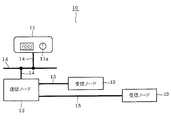
- FIG. 1 is a diagram schematically illustrating a configuration example of a communication system according to the first embodiment.
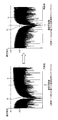
- FIG. 2 is a diagram illustrating the data transmission / reception rate based on the selected frequency before and after the change.
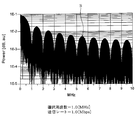
- FIG. 3 is a diagram illustrating an example of changing the data transmission / reception rate based on the selected frequency.
- FIG. 4 is a diagram showing another example of changing the data transmission / reception rate based on the selected frequency.
- FIG. 5 is a diagram showing still another example of changing the data transmission / reception rate based on the selected frequency.
- FIG. 6 is a diagram illustrating an example of a data structure that is output after the transmission node according to the second embodiment changes the transmission rate.
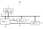
- FIG. 7 is a diagram schematically illustrating a configuration example of a communication system according to the third embodiment.
- FIG. 8 is a timing chart showing an operation example of the communication system.
- FIG. 9 is a timing chart illustrating a mute function included in a general radio.
- FIG. 10 is a timing chart showing an example when the mute function is applied to the communication system.
- FIG. 11 is a timing chart showing an example when the mute function is applied to the communication system according to the fourth embodiment.
- a communication system 10 illustrated in FIG. 1 is mounted on a vehicle and includes a car radio 11, a transmission node 12, and a reception node 13.
- the car radio 11 is an example of a radio wave receiver, and has an operation unit 11a for selecting a channel.
- the transmission node 12 and the reception node 13 are communication nodes that construct an in-vehicle LAN.
- the car radio 11 and the transmission node 12 are communicably connected via a low-speed wired communication cable 14.
- the transmission node 12 and the reception node 13 are communicably connected by a wired communication cable 15 for high-speed communication.
- the car radio 11 When the user selects a channel via the operation unit 11a, the car radio 11 notifies the transmission node 12 via the wired communication cable 14 of a selected frequency packet indicating a frequency corresponding to the channel.
- the selected frequency packet is an example of selected frequency information indicating the frequency selected in the car radio 11. Then, when receiving the selected frequency packet from the car radio 11, the transmission node 12 changes the data transmission rate from the transmission rate R1 to the transmission rate R2 based on the frequency indicated by the information, as illustrated in FIG. .
- the spectrum S of the communication waveform before changing the transmission rate is lower than the regulation level A1 at the selected frequency selected in the car radio 11, but the radio noise level A2 is lower than the regulation level A1. Is over. Therefore, noise may occur and the sound quality of the car radio 11 may be degraded. Therefore, the transmission node 12 changes the transmission rate so that the notch point N at which the spectrum S of the communication waveform becomes low overlaps the selected frequency of the car radio 11. As a result, the spectrum S of the communication waveform at the selected frequency of the car radio 11 becomes lower than the radio noise level A2. Therefore, it becomes difficult to generate noise, and a decrease in sound quality of the car radio 11 can be avoided.
- the transmission node 12 changes the transmission rate so as to satisfy the following expression (1) when the frequency selected in the car radio 11 is X [MHz] and the transmission rate is Ya [Mbps].
- the transmission node 12 appropriately adjusts the transmission rate by utilizing the notch point N of the communication waveform spectrum S in conjunction with the transmission rate, whereby the transmission waveform spectrum at the selected frequency X is obtained.
- S is set lower than the radio noise level A2.
- the radiation power of unnecessary radiation is obtained by multiplying the spectrum S of the communication waveform by the radiation characteristic.
- the radiation characteristic is difficult to control because it depends on the system.
- the control of the radiation power depends exclusively on the position of the notch point N in the spectrum S of the communication waveform, in other words, the adjustment of the transmission rate. That is, the spectrum of unnecessary radiation shows a characteristic approximate to the spectrum S of the communication waveform. Therefore, the radiation power can be efficiently controlled by adjusting the transmission rate based on the selected frequency as described above.
- noise is reduced by automatically changing the transmission rate according to the frequency selected in the car radio 11. According to this configuration, it is not necessary to add any configuration in order to avoid the deterioration of the sound quality of the car radio 11. Therefore, it is possible to avoid a decrease in sound quality of the car radio 11 without causing an increase in cost.
- the preamble data Db is added to the data body Da to be transmitted to the reception node 13, as illustrated in FIG.
- Preamble data Db is an example of transmission rate information indicating the transmission rate after the change.
- the preamble data Db is composed of, for example, 10-bit “0101...” Data.
- the receiving node 13 specifies the changed transmission rate based on the preamble data Db obtained from the transmitting node 12. In this case, the receiving node 13 specifies the changed transmission rate based on the toggle pattern of the preamble data Db. That is, the receiving node 13 specifies the changed transmission rate according to the length of time required for receiving the 10-bit preamble data Db, for example. And the receiving node 13 will change a receiving rate based on the transmission rate, if the transmission rate after a change is specified. In this case, the reception node 13 may adjust the reception rate to the same rate as the transmission rate or adjust the reception rate to a rate that is an integral multiple of the transmission rate.
- the reception rate is also adjusted based on the changed transmission rate. Therefore, rates can be matched on both the transmission side and the reception side, and noise can be reduced more effectively.
- the reception node 13 is also communicably connected to the car radio 11 via a low-speed wired communication cable 14.
- the car radio 11 transmits a selection frequency packet F indicating the selection frequency via the wired communication cable 14 and the reception node 13 as illustrated in FIG. Notify each.
- the transmitting node 12 that has received the selected frequency packet F adjusts the transmission rate based on the frequency indicated by the selected frequency packet F
- the receiving node 13 that has received the selected frequency packet F indicates the selected frequency packet F.
- the reception rate is adjusted based on the frequency.
- the data transmission / reception rate between the transmission node 12 and the reception node 13 is changed from the rate R1 that does not match the selected frequency of the car radio 11 to the rate R2 that matches the selected frequency of the car radio 11.
- the rates can be matched on both the transmission side and the reception side, and communication errors in higher-speed communication are less likely to occur.
- This embodiment is an embodiment using this mute function. That is, as illustrated in FIG. 10, when the channel of the car radio 11 is changed during high-speed communication between the transmission node 12 and the reception node 13, There is a possibility that high-speed communication with the receiving node 13 at the rate R1 before the change is continued. Therefore, there is a possibility that unnecessary radiation resulting from data communication may generate noise for the sound of the car radio 11 after the mute process is completed.
- the transmission node 12 when the transmission node 12 completes the change of the transmission rate, the transmission node 12 notifies the car radio 11 of the change completion packet P.
- the receiving node 13 also notifies the car radio 11 of the change completion packet P when the change of the reception rate is completed.
- the change completion packet P is an example of change completion information indicating that the change of the transmission rate or the reception rate is completed according to the selected frequency.
- the change completion packet P is obtained from all the nodes constituting the communication system 10 until the change completion packet P is obtained from the transmission node 12 and the reception node 13. Until the mute process continues.
- the change completion packet P is obtained from all nodes, the car radio 11 ends the mute process and returns the volume to the original level.
- the mute process continues until the transmission rate of the transmission node 12 and the reception rate of the reception node 13 are all adjusted. Therefore, it is possible to avoid unnecessary radiation caused by data communication from generating noise with respect to the sound of the car radio 11.
- the mute period is longer than that of a general radio. However, even if the mute period becomes longer, the mute period can be suppressed to 0.1 seconds or less. Therefore, there is almost no possibility that the user perceives that the mute period becomes longer.
- the change completion packet P is configured to be output by at least one of the transmission node 12 or the reception node 13, and the car radio 11 receives the change completion packet P from at least one of the transmission node 12 or the reception node 13.
- the mute process may be terminated on the condition that is obtained.
- the embodiment is not limited to the above-described embodiment, and can be variously modified.
- the spectrum S of the communication waveform has a plurality of notch points N. Therefore, the notch point N to be matched with the selected frequency of the car radio 11 is not limited to the notch point N having the lowest frequency, and any notch point N may be used.
- Wired communication connecting the car radio 11 and the communication nodes 12 and 13 is not limited to low-speed communication, and may be, for example, high-speed communication using a common mode choke, shielded cable, optical communication, etc. It is preferable that the radio 11 is less likely to be affected by noise.
- the car radio 11 may be various radio wave receivers such as an AM radio receiver, an FM radio receiver, a television broadcast receiver, or a combination thereof.
- the embodiment is not limited to the wired communication system including the car radio 11 and the in-vehicle LAN, and a wireless communication system such as a mobile communication system or a road-to-vehicle communication system can be used as the embodiment. Moreover, you may combine each above-mentioned embodiment suitably.
Landscapes
- Engineering & Computer Science (AREA)
- Computer Networks & Wireless Communication (AREA)
- Signal Processing (AREA)
- Noise Elimination (AREA)
- Communication Control (AREA)
- Cable Transmission Systems, Equalization Of Radio And Reduction Of Echo (AREA)
Abstract
コスト増大を招くことなく、ラジオなどの電波受信機の音質低下を回避することができる通信システムを提供する。通信システム(10)は、電波受信機(11)と、データを送信する送信ノード(12)と、送信ノードからデータを受信する受信ノード(13)と、を備える。送信ノード(12)は、電波受信機(11)において選択されている周波数に基づいてデータの送信レートを変更する。
Description
本出願は、2015年4月24日に出願された日本国特許出願2015-89295号に基づくものであり、その開示をここに参照により援用する。
本開示は、複数のノード間でデータを送受信する通信システムに関する。
有線通信においては、例えばツイストペアケーブルを用いて差動信号よる通信を行う場合であっても、何らかの不平衡が生じて対称性が崩れ、不要輻射の原因となるコモンモードが発生する。不要輻射の許容レベルは法律により規定されており、この許容レベル以下であれば法規上は問題とはならない。しかし、例えばAMラジオは、特に外来ノイズの影響を受けやすいため、法規上では問題無いレベルの不要輻射であっても音質の劣化などが生じる。特に自動車に搭載されるラジオについては、その音質の低下は、自動車全体としての品質の低下にもつながる。そのため、法規レベルよりも低い許容レベルを設定し、不要輻射をより厳しいレベルで規制するようにしている。
[online]、インターネット(URL:http://www.t-net.ne.jp/~kondoy/lecture/bme/09.pdf)
岩田利王著、「実践ディジタル・フィルタ設計入門」、CQ出版社、p.168-169
しかしながら、不要輻射の許容レベルを低く設定した場合には、その許容レベルを満たすべく、車両内のネットワーク通信も低いデータレートで行う必要がある。そのため、用途によってはデータレートが不足する場合があり、このような場合に対応するために、例えば複数の通信を並列的に行う構成が必要となる。また、高いデータレートが必要なネットワークを構築する場合には、コモンモードの発生を抑えるためのコモンモードチョークなどを設ける必要がある。このように、ラジオの音質低下を回避するためには何らかの構成上の追加が必要となり、コスト増大の要因となっている。
そこで、本開示の目的の一つは、コスト増大を招くことなく、ラジオなどの電波受信機の音質低下を回避することができる通信システムを提供することにある。
本開示の一例に係る通信システムは、ラジオなどの電波受信機と、データを送信する送信ノードと、送信ノードからデータを受信する受信ノードと、を備える。そして、送信ノードは、電波受信機において選択されている周波数に基づいてデータの送信レートを変更する。即ち、通信システムは、電波受信機において選択されている周波数に応じて自動的に送信レートを変更することでノイズの低減を図るようにした。この構成によれば、電波受信機の音質低下を回避するための何らかの構成上の追加が不要である。よって、コスト増大を招くことなく、ラジオなどの電波受信機の音質低下を回避することができる。
本開示についての上記および他の目的、特徴や利点は、添付図面を参照した下記詳細な説明から、より明確になる。添付図面において、
図1は、第1実施形態に係る通信システムの構成例を概略的に示す図である。
図2は、選択周波数に基づくデータの送受信レートの変更前および変更後を例示する図である。
図3は、選択周波数に基づくデータの送受信レートの変更例を示す図である。
図4は、選択周波数に基づくデータの送受信レートの他の変更例を示す図である。
図5は、選択周波数に基づくデータの送受信レートのさらに他の変更例を示す図である。
図6は、第2実施形態に係る送信ノードが送信レート変更後に出力するデータ構造の一例を示す図である。
図7は、第3実施形態に係る通信システムの構成例を概略的に示す図である。
図8は、通信システムの動作例を示すタイミングチャートである。
図9は、一般的なラジオが備えるミュート機能を例示するタイミングチャートである。
図10は、通信システムにミュート機能を適用した場合の一例を示すタイミングチャートである。
図11は、第4実施形態に係る通信システムにミュート機能を適用した場合の一例を示すタイミングチャートである。
以下、複数の実施形態について図面を参照しながら説明する。なお、各実施形態において実質的に同一の要素には同一の符号を付し、説明を省略する。
(第1実施形態)
図1に例示する通信システム10は、車両に搭載されるものであり、カーラジオ11、送信ノード12、受信ノード13を備える。カーラジオ11は、電波受信機の一例であり、チャンネルを選択するための操作部11aを有している。送信ノード12および受信ノード13は、車載LANを構築する通信ノードである。カーラジオ11と送信ノード12は、この場合、低速通信用の有線通信ケーブル14により通信可能に接続されている。送信ノード12と受信ノード13は、この場合、高速通信用の有線通信ケーブル15により通信可能に接続されている。
図1に例示する通信システム10は、車両に搭載されるものであり、カーラジオ11、送信ノード12、受信ノード13を備える。カーラジオ11は、電波受信機の一例であり、チャンネルを選択するための操作部11aを有している。送信ノード12および受信ノード13は、車載LANを構築する通信ノードである。カーラジオ11と送信ノード12は、この場合、低速通信用の有線通信ケーブル14により通信可能に接続されている。送信ノード12と受信ノード13は、この場合、高速通信用の有線通信ケーブル15により通信可能に接続されている。
カーラジオ11は、ユーザが操作部11aを介してチャンネルを選択すると、そのチャンネルに対応する周波数を示す選択周波数パケットを、有線通信ケーブル14を介して送信ノード12に通知する。選択周波数パケットは、カーラジオ11において選択されている周波数を示す選択周波数情報の一例である。そして、送信ノード12は、カーラジオ11から選択周波数パケットを受信すると、その情報が示す周波数に基づいて、図2に例示するように、データの送信レートを送信レートR1から送信レートR2に変更する。
送信レートを変更する前の通信波形のスペクトルSは、カーラジオ11において選択されている選択周波数において法規レベルA1以下にはなっているものの、この法規レベルA1よりも低いレベルであるラジオノイズレベルA2を超えている。そのため、ノイズが発生してカーラジオ11の音質が低下するおそれがある。そこで、送信ノード12は、通信波形のスペクトルSが低くなるノッチポイントNがカーラジオ11の選択周波数に重なるように送信レートを変更する。これにより、カーラジオ11の選択周波数において通信波形のスペクトルSがラジオノイズレベルA2よりも低くなる。よって、ノイズが発生しにくくなり、カーラジオ11の音質の低下を回避することができる。
また、送信ノード12は、カーラジオ11において選択されている周波数をX[MHz]、送信レートをYa[Mbps]とした場合に、次の式(1)を満たすように送信レートを変更する。
X=k×Ya・・・・・・・(1)
k:任意の整数
即ち、送信ノード12は、XがYaの整数倍となるように送信レートを変更する。図3には、X=1.0[MHz]、Ya=1.0[Mbps]の場合の通信波形のスペクトルSを示している。つまり、この場合、送信ノード12は、X=Yaとなるように送信レートを変更する。そして、周波数X=1.0[MHz]において、通信波形のスペクトルSがラジオノイズレベルA2よりも低くなった状態を実現する。
k:任意の整数
即ち、送信ノード12は、XがYaの整数倍となるように送信レートを変更する。図3には、X=1.0[MHz]、Ya=1.0[Mbps]の場合の通信波形のスペクトルSを示している。つまり、この場合、送信ノード12は、X=Yaとなるように送信レートを変更する。そして、周波数X=1.0[MHz]において、通信波形のスペクトルSがラジオノイズレベルA2よりも低くなった状態を実現する。
また、図4には、X=1.5[MHz]、Ya=1.5[Mbps]の場合の通信波形のスペクトルSを示している。つまり、この場合も、送信ノード12は、X=Yaとなるように送信レートを変更する。そして、周波数X=1.5[MHz]において、通信波形のスペクトルSがラジオノイズレベルA2よりも低くなった状態を実現する。
また、図5には、X=1.0[MHz]、Ya=0.5[Mbps]の場合の通信波形のスペクトルSを示している。つまり、この場合、送信ノード12は、X=2×Yaとなるように送信レートを変更する。そして、周波数X=0.5[MHz]において、通信波形のスペクトルSがラジオノイズレベルA2よりも低くなった状態を実現する。
このように、送信ノード12は、送信レートに連動して通信波形のスペクトルSのノッチポイントNが変動することを利用して、送信レートを適宜調整することにより、選択周波数Xにおける通信波形のスペクトルSをラジオノイズレベルA2よりも低くする。
なお、不要輻射の輻射パワーは、通信波形のスペクトルSに放射特性を掛けたものとなる。ここで、放射特性は、システムの系に依存するためコントロールすることが難しい。そのため、輻射パワーの制御は、専ら通信波形のスペクトルSにおけるノッチポイントNの位置、換言すれば送信レートの調整に依存する。即ち、不要輻射のスペクトルは、通信波形のスペクトルSに近似した特性を示す。よって、上述したように選択周波数に基づいて送信レートを調整することにより、輻射パワーを効率良く制御することができる。
通信システム10によれば、カーラジオ11において選択されている周波数に応じて自動的に送信レートを変更することでノイズの低減を図るようにした。この構成によれば、カーラジオ11の音質低下を回避するための何らかの構成上の追加が不要である。よって、コスト増大を招くことなく、カーラジオ11の音質低下を回避することができる。
(第2実施形態)
本実施形態では、送信ノード12は、カーラジオ11の選択周波数に応じて送信レートを変更すると、図6に例示するように、受信ノード13に送信するデータ本体DaにプリアンブルデータDbを付加する。プリアンブルデータDbは、変更後の送信レートを示す送信レート情報の一例である。この場合、プリアンブルデータDbは、例えば10bitの「0101・・・」データで構成されている。
本実施形態では、送信ノード12は、カーラジオ11の選択周波数に応じて送信レートを変更すると、図6に例示するように、受信ノード13に送信するデータ本体DaにプリアンブルデータDbを付加する。プリアンブルデータDbは、変更後の送信レートを示す送信レート情報の一例である。この場合、プリアンブルデータDbは、例えば10bitの「0101・・・」データで構成されている。
受信ノード13は、送信ノード12から得られるプリアンブルデータDbに基づいて、変更後の送信レートを特定する。この場合、受信ノード13は、プリアンブルデータDbのトグルパターンに基づいて、変更後の送信レートを特定する。即ち、受信ノード13は、例えば10bitのプリアンブルデータDbの受信に要した時間の長さに応じて、変更後の送信レートを特定する。そして、受信ノード13は、変更後の送信レートを特定すると、その送信レートに基づいて受信レートを変更する。この場合、受信ノード13は、送信レートと同じレートに受信レートを調整したり、あるいは、送信レートの整数倍のレートに受信レートを調整するようにするとよい。
本実施形態によれば、変更後の送信レートに基づいて受信レートも調整される。従って、送信側および受信側の双方においてレートを整合させることができ、一層効果的にノイズを低減することができる。
(第3実施形態)
図7に例示する通信システム20によれば、受信ノード13も低速通信用の有線通信ケーブル14によりカーラジオ11に通信可能に接続されている。この構成において、カーラジオ11は、選択周波数が変更されると、図8に例示するように、その選択周波数を示す選択周波数パケットFを、有線通信ケーブル14を介して送信ノード12および受信ノード13にそれぞれ通知する。そして、選択周波数パケットFを受信した送信ノード12は、その選択周波数パケットFが示す周波数に基づいて送信レートを調整し、選択周波数パケットFを受信した受信ノード13は、その選択周波数パケットFが示す周波数に基づいて受信レートを調整する。これにより、送信ノード12と受信ノード13との間におけるデータの送受信レートは、カーラジオ11の選択周波数に適合しないレートR1から、カーラジオ11の選択周波数に適合するレートR2に変更される。
図7に例示する通信システム20によれば、受信ノード13も低速通信用の有線通信ケーブル14によりカーラジオ11に通信可能に接続されている。この構成において、カーラジオ11は、選択周波数が変更されると、図8に例示するように、その選択周波数を示す選択周波数パケットFを、有線通信ケーブル14を介して送信ノード12および受信ノード13にそれぞれ通知する。そして、選択周波数パケットFを受信した送信ノード12は、その選択周波数パケットFが示す周波数に基づいて送信レートを調整し、選択周波数パケットFを受信した受信ノード13は、その選択周波数パケットFが示す周波数に基づいて受信レートを調整する。これにより、送信ノード12と受信ノード13との間におけるデータの送受信レートは、カーラジオ11の選択周波数に適合しないレートR1から、カーラジオ11の選択周波数に適合するレートR2に変更される。
本実施形態によれば、カーラジオ11から出力する選択周波数パケットFに基づいて、送信ノード12および受信ノード13の双方について送受信レートを一括して調整することができる。また、送信側および受信側の双方においてレートを整合させることができ、一層高速通信での通信エラーが発生し難くなる。
(第4実施形態)
一般的に、カーラジオ11などのラジオ機器類は、チャンネルが変更された場合には、そのチャンネルに対応する周波数に合わせるために周波数を微調整する処理を行うようになっている。そのため、この微調整処理の実行中においては、データ通信とは無関係に、ラジオの動作由来のノイズが発生する可能性がある。そのため、図9に例示するように、一般的なラジオでは、チャンネルが変更されると、所定時間の間、周波数微調整処理のための期間Tを設ける。そして、この期間Tにおいては、音声出力のボリュームを自動的に下げるミュート処理を実行するようになっている。
一般的に、カーラジオ11などのラジオ機器類は、チャンネルが変更された場合には、そのチャンネルに対応する周波数に合わせるために周波数を微調整する処理を行うようになっている。そのため、この微調整処理の実行中においては、データ通信とは無関係に、ラジオの動作由来のノイズが発生する可能性がある。そのため、図9に例示するように、一般的なラジオでは、チャンネルが変更されると、所定時間の間、周波数微調整処理のための期間Tを設ける。そして、この期間Tにおいては、音声出力のボリュームを自動的に下げるミュート処理を実行するようになっている。
本実施形態は、このミュート機能を利用した実施形態である。即ち、図10に例示するように、送信ノード12と受信ノード13との高速通信の途中において、カーラジオ11のチャンネルが変更される場合には、ミュート処理の終了後においても、送信ノード12と受信ノード13との間で、変更前のレートR1による高速通信が継続している可能性がある。そのため、ミュート処理の終了後において、データ通信に起因する不要輻射がカーラジオ11の音声に対してノイズを発生するおそれがある。
そこで、本実施形態では、図11に例示するように、送信ノード12は、送信レートの変更を完了すると変更完了パケットPをカーラジオ11に通知する。また、受信ノード13も、受信レートの変更を完了すると変更完了パケットPをカーラジオ11に通知する。変更完了パケットPは、選択周波数に応じて送信レートあるいは受信レートの変更を完了したことを示す変更完了情報の一例である。そして、カーラジオ11は、周波数が変更されると、送信ノード12および受信ノード13から変更完了パケットPが得られるまで、つまり、通信システム10を構築する全てのノードから変更完了パケットPが得られるまで、ミュート処理を継続する。そして、カーラジオ11は、全てのノードから変更完了パケットPが得られると、ミュート処理を終了してボリュームを元のレベルに戻す。
本実施形態によれば、送信ノード12の送信レートおよび受信ノード13の受信レートが全て調整されるまでミュート処理が継続する。従って、データ通信に起因する不要輻射が、カーラジオ11の音声に対してノイズを発生することを回避することができる。なお、本実施形態によれば、一般的なラジオに比べ、ミュート期間が長くなる。しかし、長くなったとしても、そのミュート期間は0.1秒以下に抑えることが可能であり、従って、ミュート期間が長くなったことをユーザに知覚されるおそれは殆ど無い。
なお、変更完了パケットPは、送信ノード12または受信ノード13の少なくとも何れか一方が出力するように構成し、カーラジオ11は、送信ノード12または受信ノード13の少なくとも何れか一方から変更完了パケットPが得られたことを条件にミュート処理を終了するように構成してもよい。
(その他の実施形態)
実施形態は、上述した実施形態に限定されるものではなく、種々に変形できる。
実施形態は、上述した実施形態に限定されるものではなく、種々に変形できる。
受信ノード13は、送信ノード12と同様に、カーラジオ11の選択周波数X[MHz]が受信レートYb[Mbps]の整数倍となるように受信レートを変更するように構成することができ、また、X=Ybとなるように受信レートを変更するように構成することが可能である。このように、受信ノード13における受信レートの調整処理を送信ノード12における送信レートの調整処理と同じようにすることで、送信側と受信側で調和のとれたレートの調整を行うことができ、より効果的にノイズを低減することができる。
通信波形のスペクトルSは、複数のノッチポイントNを有している。そのため、カーラジオ11の選択周波数に合わせるノッチポイントNは、周波数が最も小さいノッチポイントNに限らず、何れのノッチポイントNを利用してもよい。
カーラジオ11と通信ノード12,13とを接続する有線通信は、低速通信に限られるものではなく、例えば、コモンモードチョークを用いた高速通信、シールドケーブル、光通信などであってもよく、カーラジオ11にノイズの影響を与えにくいものであることが好ましい。
カーラジオ11は、AMラジオ受信機、FMラジオ受信機、テレビ放送受信機などといった種々の電波受信機、あるいは、これらを組み合わせたものであってもよい。
実施形態は、カーラジオ11と車載LANからなる有線通信システムに限らず、例えば、携帯通信システムや路車間通システムなどといった無線通信システムも実施形態とすることができる。また、上述の各実施形態を適宜組み合わせてもよい。
Claims (11)
- 電波受信機(11)と、
データを送信する送信ノード(12)と、
前記送信ノードからデータを受信する受信ノード(13)と、を備える通信システムであって、
前記送信ノードは、前記電波受信機において選択されている周波数に基づいてデータの送信レートを変更する、
通信システム。 - 前記送信ノードは、前記電波受信機において選択されている周波数をX[MHz]、前記送信レートをYa[Mbps]とした場合に、XがYaの整数倍となるように前記送信レートを変更する、
請求項1に記載の通信システム。 - 前記送信ノードは、X=Yaとなるように前記送信レートを変更する、
請求項2に記載の通信システム。 - 前記送信ノードは、前記送信レートの変更を完了すると変更完了情報を前記電波受信機に通知する、
請求項1から3の何れか1項に記載の通信システム。 - 前記電波受信機は、周波数が変更されると、前記送信ノードから前記変更完了情報が得られるまでミュート処理を継続する、
請求項4に記載の通信システム。 - 前記送信ノードは、前記受信ノードに送信するデータに変更後の前記送信レートを示す送信レート情報を付加し、
前記受信ノードは、前記送信レート情報が示す送信レートに基づいてデータの受信レートを変更する、
請求項1から5の何れか1項に記載の通信システム。 - 前記受信ノードは、前記電波受信機において選択されている周波数に基づいてデータの受信レートを変更する、
請求項1から5の何れか1項に記載の通信システム。 - 前記受信ノードは、前記電波受信機において選択されている周波数をX[MHz]、前記受信レートをYb[Mbps]とした場合に、XがYbの整数倍となるように前記受信レートを変更する、
請求項6または7に記載の通信システム。 - 前記受信ノードは、X=Ybとなるように前記受信レートを変更する、
請求項8に記載の通信システム。 - 前記受信ノードは、前記受信レートの変更を完了すると変更完了情報を前記電波受信機に通知する、
請求項6から9の何れか1項に記載の通信システム。 - 前記電波受信機は、周波数が変更されると、前記受信ノードから前記変更完了情報が得られるまでミュート処理を継続する、
請求項10に記載の通信システム。
Priority Applications (1)
| Application Number | Priority Date | Filing Date | Title |
|---|---|---|---|
| US15/565,706 US10050724B2 (en) | 2015-04-24 | 2016-03-28 | Communication system |
Applications Claiming Priority (2)
| Application Number | Priority Date | Filing Date | Title |
|---|---|---|---|
| JP2015089295A JP6369384B2 (ja) | 2015-04-24 | 2015-04-24 | 通信システム |
| JP2015-089295 | 2015-04-24 |
Publications (1)
| Publication Number | Publication Date |
|---|---|
| WO2016170736A1 true WO2016170736A1 (ja) | 2016-10-27 |
Family
ID=57143853
Family Applications (1)
| Application Number | Title | Priority Date | Filing Date |
|---|---|---|---|
| PCT/JP2016/001785 Ceased WO2016170736A1 (ja) | 2015-04-24 | 2016-03-28 | 通信システム |
Country Status (3)
| Country | Link |
|---|---|
| US (1) | US10050724B2 (ja) |
| JP (1) | JP6369384B2 (ja) |
| WO (1) | WO2016170736A1 (ja) |
Families Citing this family (2)
| Publication number | Priority date | Publication date | Assignee | Title |
|---|---|---|---|---|
| CN107770848B (zh) | 2016-08-15 | 2020-09-11 | 华为技术有限公司 | 通信系统中传输唤醒包的方法和设备 |
| JP7386427B2 (ja) * | 2020-01-20 | 2023-11-27 | パナソニックIpマネジメント株式会社 | 通信装置、通信システム |
Citations (4)
| Publication number | Priority date | Publication date | Assignee | Title |
|---|---|---|---|---|
| JPH03101317A (ja) * | 1989-09-13 | 1991-04-26 | Sony Corp | 受信機 |
| JP2004215038A (ja) * | 2003-01-06 | 2004-07-29 | Sumitomo Electric Ind Ltd | 車両内通信システム、車両内通信方法及び周波数設定装置 |
| JP2006303795A (ja) * | 2005-04-19 | 2006-11-02 | Pioneer Electronic Corp | 受信装置、受信方法及び受信制御プログラム |
| JP2014158208A (ja) * | 2013-02-18 | 2014-08-28 | Honda Motor Co Ltd | 車両用通信装置 |
Family Cites Families (3)
| Publication number | Priority date | Publication date | Assignee | Title |
|---|---|---|---|---|
| JP2002185490A (ja) * | 2000-12-19 | 2002-06-28 | Denso Corp | 通信システム及び端末装置 |
| US7457604B2 (en) * | 2003-09-18 | 2008-11-25 | General Motors Corporation | Method for suppressing motor vehicle radio interference |
| JP2014093682A (ja) | 2012-11-05 | 2014-05-19 | Denso Corp | 通信システム |
-
2015
- 2015-04-24 JP JP2015089295A patent/JP6369384B2/ja not_active Expired - Fee Related
-
2016
- 2016-03-28 US US15/565,706 patent/US10050724B2/en not_active Expired - Fee Related
- 2016-03-28 WO PCT/JP2016/001785 patent/WO2016170736A1/ja not_active Ceased
Patent Citations (4)
| Publication number | Priority date | Publication date | Assignee | Title |
|---|---|---|---|---|
| JPH03101317A (ja) * | 1989-09-13 | 1991-04-26 | Sony Corp | 受信機 |
| JP2004215038A (ja) * | 2003-01-06 | 2004-07-29 | Sumitomo Electric Ind Ltd | 車両内通信システム、車両内通信方法及び周波数設定装置 |
| JP2006303795A (ja) * | 2005-04-19 | 2006-11-02 | Pioneer Electronic Corp | 受信装置、受信方法及び受信制御プログラム |
| JP2014158208A (ja) * | 2013-02-18 | 2014-08-28 | Honda Motor Co Ltd | 車両用通信装置 |
Also Published As
| Publication number | Publication date |
|---|---|
| JP2016208344A (ja) | 2016-12-08 |
| US20180076905A1 (en) | 2018-03-15 |
| JP6369384B2 (ja) | 2018-08-08 |
| US10050724B2 (en) | 2018-08-14 |
Similar Documents
| Publication | Publication Date | Title |
|---|---|---|
| CN107493605B (zh) | 频域资源的设置方法、装置及基站 | |
| US9584911B2 (en) | Multichip dynamic range enhancement (DRE) audio processing methods and apparatuses | |
| US20150085909A1 (en) | Methods for canceling interfering wireless signals in cable customer premises equipment devices and outside plant | |
| KR20120046250A (ko) | 다중-전파 공존을 위한 결정 알고리즘들 | |
| WO2012148416A1 (en) | Concurrent transmission of wi-fi and bluetooth signals | |
| KR102240057B1 (ko) | 버스 시스템용 가입자국, 그리고 버스 시스템 내의 라인 전도성 방출을 감소시키는 방법 | |
| WO2017035742A1 (zh) | 调度方法和设备 | |
| CN107294694B (zh) | 用于全双工串行链路通信系统的可配置双向收发机 | |
| US9510301B2 (en) | Method and apparatus for adjusting transmit power | |
| CN110999132A (zh) | 通过切换进行可选择滤波 | |
| CN109474410B (zh) | 传输信道状态信息的方法和装置 | |
| JP6369384B2 (ja) | 通信システム | |
| US8682174B2 (en) | Optical receiver, optical communication system using the same and equalization method in the optical communication system | |
| US8483293B2 (en) | Method and device for signal processing | |
| JP4468359B2 (ja) | 受信回路と、それを用いた受信装置および送受信装置 | |
| JP2017510215A (ja) | データ伝送レートを調整するための方法および装置 | |
| JP2010272997A (ja) | 受信装置 | |
| US9578161B2 (en) | Method for metadata-based collaborative voice processing for voice communication | |
| WO2015003388A1 (zh) | 一种削波方法、装置及系统 | |
| CN116547913A (zh) | 全双工收发器及其操作方法 | |
| JP6155085B2 (ja) | ワイヤレスマイク用ofdm送信装置、受信装置及び送受信システム | |
| CN207082215U (zh) | 基于wifi的无人机控制系统、控制终端和无人机 | |
| US20100027716A1 (en) | Autonomous control unit and receiver using the same | |
| CN110661736B (zh) | 信号处理方法及相关装置 | |
| US10820102B1 (en) | Vehicle and method of controlling the same |
Legal Events
| Date | Code | Title | Description |
|---|---|---|---|
| 121 | Ep: the epo has been informed by wipo that ep was designated in this application |
Ref document number: 16782764 Country of ref document: EP Kind code of ref document: A1 |
|
| WWE | Wipo information: entry into national phase |
Ref document number: 15565706 Country of ref document: US |
|
| NENP | Non-entry into the national phase |
Ref country code: DE |
|
| 122 | Ep: pct application non-entry in european phase |
Ref document number: 16782764 Country of ref document: EP Kind code of ref document: A1 |