WO2016167244A1 - 偏光光照射装置 - Google Patents
偏光光照射装置 Download PDFInfo
- Publication number
- WO2016167244A1 WO2016167244A1 PCT/JP2016/061791 JP2016061791W WO2016167244A1 WO 2016167244 A1 WO2016167244 A1 WO 2016167244A1 JP 2016061791 W JP2016061791 W JP 2016061791W WO 2016167244 A1 WO2016167244 A1 WO 2016167244A1
- Authority
- WO
- WIPO (PCT)
- Prior art keywords
- polarizer
- spring
- wall
- polarized light
- light irradiation
- Prior art date
- Legal status (The legal status is an assumption and is not a legal conclusion. Google has not performed a legal analysis and makes no representation as to the accuracy of the status listed.)
- Ceased
Links
Images






Classifications
-
- G—PHYSICS
- G02—OPTICS
- G02B—OPTICAL ELEMENTS, SYSTEMS OR APPARATUS
- G02B5/00—Optical elements other than lenses
- G02B5/30—Polarising elements
-
- G—PHYSICS
- G02—OPTICS
- G02F—OPTICAL DEVICES OR ARRANGEMENTS FOR THE CONTROL OF LIGHT BY MODIFICATION OF THE OPTICAL PROPERTIES OF THE MEDIA OF THE ELEMENTS INVOLVED THEREIN; NON-LINEAR OPTICS; FREQUENCY-CHANGING OF LIGHT; OPTICAL LOGIC ELEMENTS; OPTICAL ANALOGUE/DIGITAL CONVERTERS
- G02F1/00—Devices or arrangements for the control of the intensity, colour, phase, polarisation or direction of light arriving from an independent light source, e.g. switching, gating or modulating; Non-linear optics
- G02F1/01—Devices or arrangements for the control of the intensity, colour, phase, polarisation or direction of light arriving from an independent light source, e.g. switching, gating or modulating; Non-linear optics for the control of the intensity, phase, polarisation or colour
- G02F1/13—Devices or arrangements for the control of the intensity, colour, phase, polarisation or direction of light arriving from an independent light source, e.g. switching, gating or modulating; Non-linear optics for the control of the intensity, phase, polarisation or colour based on liquid crystals, e.g. single liquid crystal display cells
- G02F1/133—Constructional arrangements; Operation of liquid crystal cells; Circuit arrangements
- G02F1/1333—Constructional arrangements; Manufacturing methods
- G02F1/1337—Surface-induced orientation of the liquid crystal molecules, e.g. by alignment layers
Definitions
- the present invention relates to a polarized light irradiation apparatus.
- Patent Document 1 discloses a polarizing element unit that fixes a wire grid polarizing element by arranging a plurality of wire grid polarizing elements on a lower frame and covering the upper frame from above.
- a polarizer support member or frame formed of metal and a wire grid polarizing element formed of glass are deformed when the temperature rises to a certain temperature, for example, about 200 degrees. The amount is different.
- the wire grid polarizing element is sandwiched between the frames, and there is no gap between the wire grid polarizing element and the frame.
- a problem such as breakage of the wire grid polarizing element may occur due to a difference in dimensions due to thermal expansion between the wire grid polarizing element and the polarizer support member.
- the present invention has been made in view of such circumstances, and an object thereof is to provide a polarized light irradiation apparatus capable of preventing problems due to thermal expansion.
- a polarized light irradiation apparatus includes, for example, a light source, a plate-like polarizer having a substantially rectangular shape in a plan view that polarizes light emitted from the light source, and the polarizer.
- a holding member having a wall against which a side surface of the polarizer contacts, and an elastic member provided on the holding member and contacting the first side surface of the polarizer, the polarizer And an elastic member that urges a side surface facing the first side surface toward the wall.
- the elastic member abuts on the first side surface of the plate-like polarizer having a substantially rectangular shape in plan view that polarizes light from the light source.
- the elastic member biases the side surface facing the first side surface of the polarizer toward the wall of the holding member.
- the elastic member includes a first elastic member that contacts the first side surface of the polarizer, and a second elastic member that contacts the second side surface adjacent to the first side surface of the polarizer.
- the wall includes a first wall and a second wall that are two orthogonal walls, and the first elastic member is opposed to the first side surface of the polarizer.
- the second elastic member urges the side surface of the polarizer facing the second side surface toward the second side surface. May be. Thereby, the polarizer can be positioned with respect to the holding member on a plane orthogonal to the first side surface of the polarizer.
- the elastic member is a spring-loaded screw having a ball that contacts the polarizer, a spring that urges the ball toward the polarizer, and a screw portion in which the spring is provided.
- a thickness of the polarizer may be larger than a diameter of the screw portion.
- the elastic member may include two springs, and the two springs may respectively press the vicinity of both ends of the first side surface.
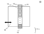
- FIG. 2 is a plan view illustrating an outline of a polarized light irradiation unit 10.
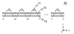
- FIG. 2 is a side view illustrating an outline of a polarized light irradiation unit 10.
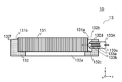
- FIG. 2 is a plan view showing an outline of a polarizer unit 13.
- FIG. 3 is a cross-sectional view showing an outline of a polarizer unit 13.
- FIG. It is a figure which shows the outline of the conventional form which urges
- FIG. 1 is a front view showing an outline of a polarized light irradiation apparatus 1 according to the first embodiment.
- FIG. 2 is a side view showing an outline of the polarized light irradiation apparatus 1.
- the polarized light irradiation apparatus 1 obtains polarized light by passing light from a light source through a polarizing film, and irradiates the exposed surface of a glass substrate or the like to generate an alignment film or the like for a liquid crystal panel. It is.
- the transport direction of the object to be exposed W will be referred to as the y direction, the direction orthogonal to the transport direction as the x direction, and the vertical direction as the z direction.
- the polarized light irradiation device 1 mainly includes a polarized light irradiation unit 10, a drive unit 20, and an imaging unit 30.
- FIG. 2 is a plan view showing an outline of the polarized light irradiation unit 10.
- FIG. 3 is a side view showing an outline of the polarized light irradiation unit 10. Note that the two-dot chain line in FIG. 3 indicates a range in which light is irradiated.
- the polarized light irradiation unit 10 mainly includes a light source 11, a specific wavelength transmission filter 12, a polarizer unit 13, and a base member 14. In FIG. 2, the specific wavelength transmission filter 12 is not shown.
- the light source 11 is a rod-shaped lamp and emits unpolarized light (for example, ultraviolet light).
- a plurality of light sources are arranged side by side in the x direction so that the longitudinal direction is along the y direction. Note that the form of the light source 11 is not limited to this, and may be, for example, a single lamp that is long along the x direction.
- the specific wavelength transmission filter 12 is a filter that transmits only light in a specific wavelength range and absorbs light of other wavelengths.
- the specific wavelength transmission filter 12 is provided below the light source 11 ( ⁇ z side).
- the polarizer unit 13 is provided on the lower side ( ⁇ z side) of the specific wavelength transmission filter 12.
- the polarizer unit 13 includes, for example, a polarizer that polarizes unpolarized light emitted from the light source 11.
- the polarizer unit 13 is provided on the base member 14. The polarizer unit 13 will be described in detail later.
- One specific wavelength transmission filter 12 and one polarizer unit 13 are provided for each light source 11. Two specific wavelength transmission filters 12 and two polarizer units 13 may be provided for each light source 11. In this case, the specific wavelength transmission filter 12 and the polarizer unit 13 may be provided two by two in the y direction (see the dotted line in FIG. 2).
- the drive unit 20 mainly includes a stage 21 and a stage guide rail 22.
- the stage 21 is provided so as to be movable along the stage guide rail 22 by a driving means (not shown) (see a thick arrow in FIG. 1). An object to be exposed W is placed on the upper surface of the stage 21.
- the imaging unit 30 is a camera used for alignment of the object to be exposed W placed on the stage 21.
- the operation of the polarized light irradiation apparatus 1 configured as described above will be described.
- the polarized light irradiation apparatus 1 irradiates the exposure surface of the object to be exposed W with the light irradiated from the polarization irradiation unit 10 while moving the object to be exposed W in the y direction that is the scanning direction. Is generated. Since the operation of this polarized light irradiation apparatus 1 is already known, detailed description thereof is omitted.
- the polarized light irradiation unit 10 may be moved, the object to be exposed W (stage 21) may be moved, or both of them may be relatively moved.
- the present invention is characterized in that it prevents a problem caused by an increase in the temperature of the polarizer unit 13.
- the polarizer unit 13 will be described in detail.
- FIG. 4 is a plan view showing an outline of the polarizer unit 13.
- FIG. 5 is a cross-sectional view schematically showing the polarizer unit 13.
- the polarizer unit 13 mainly includes a polarizer 131, a holder 132, and a spring screw 133 (the spring screw 133 includes a spring screw 133A, a spring screw 133B, and a spring screw 133C).
- the polarizer 131 is an optical element that polarizes light from the light source 11 and is a plate-like member having a substantially rectangular shape in plan view.
- the polarizer 131 is formed by, for example, periodically arranging metal wires in one direction on the surface of a plate made of glass.
- the thickness of the polarizer 131 is thicker than the diameter of the threaded portion 133a (detailed later) of the spring-loaded screw 133.
- the thickness of the polarizer 131 is about 3 mm to 7 mm.
- the holder 132 (corresponding to a holding member) is a plate-like member that is made of metal and has a substantially hollow rectangular shape in plan view.
- the holder 132 is formed with a hole 132a and a recess 132b.
- the polarizer 131 is placed on the bottom surface 132c of the recess 132b. The light polarized by the polarizer 131 is irradiated downward ( ⁇ z direction) through the hole 132a.
- the spring-loaded screw 133 includes, for example, a ball plan having a threaded portion 133a, a ball 133b that contacts the polarizer 131, and a coil spring 133c (corresponding to an elastic member) that urges the ball 133b toward the polarizer 131.
- Jar. The ball 133b and the coil spring 133c are provided inside the threaded portion 133a.
- the two spring-loaded screws 133A and 133B are provided on the wall 132d.
- a screw hole (not shown) is formed in the wall 132d, and the screw portion 133a is screwed into the screw hole, whereby spring-equipped screws 133A and 133B are provided in the wall 132d.
- one spring-loaded screw 133C is provided on the wall 132e.
- a screw hole (not shown) is formed in the wall 132e, and the screw portion 133a is screwed into the screw hole, whereby the spring-loaded screw 133C is provided in the wall 132e.
- the spring-loaded screw 133 Since the threaded portion 133a is screwed into the screw hole formed in the holder 132, the spring-loaded screw 133 is movable in the normal direction of the walls 132d and 132e of the holder 132 (see thick arrows in FIGS. 4 and 5). ).
- the spring-loaded screws 133A and 133B are in contact with the side surface 131a of the polarizer 131.
- the coil springs 133c of the spring-loaded screws 133A and 133B urge the side surface 131b facing the side surface 131a of the polarizer 131 toward the wall 132f via the ball 133b (see arrows in FIGS. 4 and 5).
- the spring-loaded screws 133A and 133B press the vicinity of both ends of the side surface 131a in order to prevent the polarizer 131 from rotating when the side surface 131b is urged toward the wall 132f.
- the vicinity of both ends of the side surface 131a is not limited to the position shown in FIG.
- the spring-loaded screw 133 ⁇ / b> C contacts the side surface 131 c adjacent to the side surface 131 a of the polarizer 131.
- the coil spring 133c of the spring-loaded screw 133C urges the side surface 131d facing the side surface 131c of the polarizer 131 through the ball 133b toward the wall 132g (see the arrow in FIG. 4).
- the force in the direction (x direction or y direction) orthogonal to the thickness direction (z direction) of the polarizer 131 is biased to the polarizer 131 by the coil spring 133c on the side surface 131a and the side surface 131c.
- the polarizer 131 is provided on the holder 132.
- the wall 132f and the wall 132g are adjacent to each other, the wall 132f is parallel to the x direction, and the wall 132g is parallel to the y direction.
- the polarizer 131 is pressed against the walls 132f and 132g by the coil spring 133c, the polarizer 131 is positioned with respect to the holder 132 on a plane parallel to the xy plane.
- the polarizer 131 by pressing the polarizer 131 against the walls 132f and 132g of the holder 132, it is possible to prevent problems due to thermal expansion while providing the polarizer 131 on the holder 132.
- the polarizer 131 When the polarizer 131 is bonded to the holder 132 as in the prior art, the polarizer 131 may be broken because the dimensional change due to thermal expansion is different between the polarizer 131 and the holder 132.
- the polarizer 131 is provided on the holder 132 using an elastic member, so that the polarizer 131 can be prevented from being broken.
- a polarizer unit 130 is also provided in which the polarizer 131 is provided on the holder 132 by urging the polarizer 131 to the bottom surface 132c (pressing in the ⁇ z direction) using a leaf spring 134. Conceivable. In this case, the risk that the polarizer 131 will break is small. However, in order to provide the polarizer 131 in the recess 132b, it is necessary to make the size of the recess 132b larger than the size of the polarizer 131 in view of the thermal expansion of the polarizer 131. Therefore, when thermal expansion and contraction are repeated, the polarizer 131 may rotate in the recess 132b as shown in FIG.
- the polarizer 131 since the polarizer 131 is thick, a force in the x direction or the y direction perpendicular to the z direction can be directly urged to the polarizer 131 by the coil spring 133c. Therefore, by positioning the polarizer 131 with respect to the holder 132 on a plane parallel to the xy plane, the polarizer 131 can be placed in the holder 132 even when the dimensional change due to thermal expansion differs between the polarizer 131 and the holder 132. Can be prevented from rotating (including movement, the same applies hereinafter).
- the thickness of the polarizer 131 is thicker than the diameter of the threaded portion 133a of the spring-loaded screw 133, but the thickness of the polarizer 131 is not limited to this.
- the thickness of the polarizer 131 may be a thickness that allows the ball 133b of the spring-loaded screw 133 to come into contact with the coil 131 and the coil spring 133c to urge the force.
- the rotation of the polarizer 131 is prevented by pressing the side surface 131b against the wall 132f and the side surface 131d against the wall 132g.
- at least The side surface 131b may be pressed against the wall 132f.
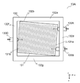
- FIG. 8 is a plan view schematically showing a polarizer unit 13A according to a modification.
- Spring-loaded screws 133A, 133B are provided on the wall 132d, and spring-loaded screws 133D are provided on the wall 132f.
- the spring-loaded screws 133A and 133B are movable with respect to the wall 132d, and the spring-loaded screw 133D is movable with respect to the wall 132f (see thick arrows in FIG. 8).
- the configuration of the spring-loaded screw 133D is the same as that of the spring-loaded screws 133A and 133B.
- the y-direction position of the spring-loaded screw 133D is adjusted, and then the y-direction positions of the spring-loaded screws 133A and 133B are respectively adjusted. Thereby, the polarizer 131 can be rotated to an arbitrary angle.
- a force in the ⁇ y direction is applied to the polarizer 131 by the coil spring 133c of the spring-loaded screws 133A and 133B. Accordingly, the side surface 131b is pressed against the wall 132f in a state where the polarizer 131 is rotated to an arbitrary angle.
- a force is applied to the side surface of the polarizer 131 using the spring-loaded screw 133 having the coil spring 133c.
- the elastic member that urges the force to the side surface of the polarizer 131 is It is not limited to this.
- a force is applied to the side surface of the polarizer using a leaf spring.
- the polarized light irradiation apparatus according to the second embodiment will be described below. Since the difference between the polarized light irradiation device 1 of the first embodiment and the polarized light irradiation device of the second embodiment is only the polarized light irradiation unit, only the polarized light irradiation unit will be described below. Further, the same parts as those of the first embodiment are denoted by the same reference numerals, and description thereof is omitted.
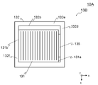
- FIG. 9 is a plan view showing an outline of the polarizer unit 13B in the polarized light irradiation unit 10A of the second embodiment.
- FIG. 10 is a cross-sectional view schematically showing the polarizer unit 13B.
- the polarized light irradiation unit 10 ⁇ / b> A mainly includes a light source 11, a specific wavelength transmission filter 12, a polarizer unit 13 ⁇ / b> B, and a base member 14.
- the polarizer unit 13 ⁇ / b> B mainly includes a polarizer 131, a holder 132, and a leaf spring 135.
- the plate spring 135 is formed by bending a metal plate material.
- the leaf spring 135 is provided on the wall 132d and contacts the side surface 131a of the polarizer 131.
- the leaf spring 135 biases the side surface 131b toward the wall 132f.
- the leaf spring 135 is formed by using a wide plate material so that the side 131a can be rotated without being rotated.
- the width of the leaf spring 135 is not limited to the case shown in FIG. Moreover, you may provide two leaf
- the polarizer 131 it is possible to prevent the polarizer 131 from rotating with respect to the holder 132 due to thermal expansion or contraction by pressing the polarizer 131 against the wall 132f.
- the polarizer 131 is positioned with respect to the holder 132 using the spring-loaded screw 133 having the coil spring 133c, but the holder 132 is not essential.
- the polarizer unit 13 that is, the holder 132 provided with the polarizer 131 is attached to the base member 14.
- the polarizer 131 may be directly provided on the base member 14 without using the holder 132.
- a polarizer is directly provided on the base member.
- the polarized light irradiation apparatus according to the third embodiment will be described. Since the difference between the polarized light irradiation device 1 of the first embodiment and the polarized light irradiation device of the third embodiment is only the polarized light irradiation unit, hereinafter the polarized light irradiation unit of the third embodiment. Only explained. Further, the same parts as those of the first embodiment are denoted by the same reference numerals, and description thereof is omitted.
- FIG. 11 is a perspective view illustrating an outline of a polarizer unit 13C in the polarized light irradiation unit 10B according to the third embodiment.
- the polarized light irradiation unit 10B mainly includes a light source 11, a specific wavelength transmission filter 12, and a polarizer unit 13C.
- the polarizer unit 13 ⁇ / b> C mainly includes a polarizer 131, a spring-loaded screw 133, and a base member 136.
- the base member 136 (corresponding to a holding member) is formed of a metal plate material. Walls 136a and 136b and a hole 136c are formed in the base member 136. The polarizer 131 is placed on the base member 136 so as to cover the hole 136c.
- the two spring-loaded screws 133 are provided on the wall 136b.
- a screw hole (not shown) is formed in the wall 136b, and the screw portion 133a is screwed into the screw hole, whereby the spring-loaded screw 133 is provided so as to be movable in the x direction.
- the spring-loaded screw 133 is in contact with the side surface 131d of the polarizer 131.
- the coil spring 133c of the spring-loaded screw 133 biases the side surface 131c opposite to the side surface 131d of the polarizer 131 toward the wall 136a via the ball 133b.
- the spring-loaded screw 133 presses the vicinity of both ends of the side surface 131d in order to prevent the polarizer 131 from rotating on the xy plane.
- the polarizer 131 can be prevented from rotating with respect to the base member 136 due to thermal expansion or contraction by pressing the polarizer 131 against the wall 136a.
- the polarizer 131 is rotated at an arbitrary angle by providing the wall 136a with a spring 133.
- the side surface 131c can be pressed against the wall 136a.
- the polarizer 131 can be biased to the wall 136a using a leaf spring.
- substantially is a concept that includes not only a case where they are exactly the same but also errors and deformations that do not lose the identity.
- the approximate center is not limited to the exact center.
- the “neighborhood” is a concept indicating that when it is in the vicinity of A, for example, it is near A and may or may not include A.
- Polarized light irradiation device 10 Polarized light irradiation unit 11: Light source 12: Specific wavelength transmission filters 13, 13A, 13B, 13C: Polarizer unit 20: Drive unit 21: Stage 22: Stage guide rail 30: Imaging unit 131: Polarization Child 131a, 131b, 131c, 131d: Side surface 132: Holder 132a: Hole 132b: Recess 132c: Bottom surface 132d, 132e, 132f, 132g: Wall 133, 133A, 133B, 133C, 133D: Spring-loaded screw 133a: Screw portion 133b: Ball 133c: coil springs 134, 135: leaf spring 136: base member 136a, 136b: wall 136c: hole
Landscapes
- Physics & Mathematics (AREA)
- Nonlinear Science (AREA)
- General Physics & Mathematics (AREA)
- Optics & Photonics (AREA)
- Spectroscopy & Molecular Physics (AREA)
- Mathematical Physics (AREA)
- Chemical & Material Sciences (AREA)
- Crystallography & Structural Chemistry (AREA)
- Polarising Elements (AREA)
- Liquid Crystal (AREA)
Priority Applications (2)
| Application Number | Priority Date | Filing Date | Title |
|---|---|---|---|
| KR1020177027259A KR20170136518A (ko) | 2015-04-14 | 2016-04-12 | 편광 광조사 장치 |
| CN201680020866.6A CN107430305A (zh) | 2015-04-14 | 2016-04-12 | 偏振光照射装置 |
Applications Claiming Priority (2)
| Application Number | Priority Date | Filing Date | Title |
|---|---|---|---|
| JP2015-082804 | 2015-04-14 | ||
| JP2015082804A JP6500204B2 (ja) | 2015-04-14 | 2015-04-14 | 偏光光照射装置 |
Publications (1)
| Publication Number | Publication Date |
|---|---|
| WO2016167244A1 true WO2016167244A1 (ja) | 2016-10-20 |
Family
ID=57126790
Family Applications (1)
| Application Number | Title | Priority Date | Filing Date |
|---|---|---|---|
| PCT/JP2016/061791 Ceased WO2016167244A1 (ja) | 2015-04-14 | 2016-04-12 | 偏光光照射装置 |
Country Status (5)
| Country | Link |
|---|---|
| JP (1) | JP6500204B2 (enExample) |
| KR (1) | KR20170136518A (enExample) |
| CN (1) | CN107430305A (enExample) |
| TW (1) | TWI728970B (enExample) |
| WO (1) | WO2016167244A1 (enExample) |
Cited By (1)
| Publication number | Priority date | Publication date | Assignee | Title |
|---|---|---|---|---|
| KR20180061047A (ko) * | 2016-11-29 | 2018-06-07 | 상하이 마이크로 일렉트로닉스 이큅먼트(그룹) 컴퍼니 리미티드 | 와이어 그리드 유닛 및 와이어 그리드 결합 보호 장치 |
Families Citing this family (1)
| Publication number | Priority date | Publication date | Assignee | Title |
|---|---|---|---|---|
| GB2700059A (en) * | 2024-02-09 | 2025-09-03 | Manchester Mfg Group Ltd | Mounting apparatus for use in supporting window coverings |
Citations (3)
| Publication number | Priority date | Publication date | Assignee | Title |
|---|---|---|---|---|
| JP2012093692A (ja) * | 2010-09-28 | 2012-05-17 | Ushio Inc | 光照射装置および光照射方法 |
| JP2014010388A (ja) * | 2012-07-02 | 2014-01-20 | Harison Toshiba Lighting Corp | 偏光光照射装置 |
| WO2014062800A1 (en) * | 2012-10-18 | 2014-04-24 | Polarization Solutions, Llc | Apparatus and method for mosaic gratings-based polarizer |
Family Cites Families (13)
| Publication number | Priority date | Publication date | Assignee | Title |
|---|---|---|---|---|
| CN2496686Y (zh) * | 2001-09-20 | 2002-06-26 | 宝安区公明镇东坑海王星运动用品厂 | 可伸缩万向脚轮 |
| CN2803895Y (zh) * | 2004-11-29 | 2006-08-09 | 萧博文 | 一种自行车转轴定位装置 |
| US20070127144A1 (en) * | 2005-12-06 | 2007-06-07 | Eastman Kodak Company | Optical film and frame with high resistance to thermal distortion |
| CN101363170B (zh) * | 2008-09-12 | 2012-05-02 | 浙江宝石机电股份有限公司 | 缝纫机滚轮调节装置 |
| CN201359237Y (zh) * | 2009-03-06 | 2009-12-09 | 北京京东方光电科技有限公司 | 背光模组 |
| JP5200271B1 (ja) * | 2012-01-25 | 2013-06-05 | ウシオ電機株式会社 | 偏光光照射装置 |
| JP2013160863A (ja) * | 2012-02-02 | 2013-08-19 | Jiroo Corporate Plan:Kk | 偏光子保護フィルム、偏光板及び液晶表示素子 |
| CN102635816B (zh) * | 2012-03-29 | 2015-09-09 | 深圳市华星光电技术有限公司 | 背光模块及液晶显示装置 |
| JP5652424B2 (ja) * | 2012-04-03 | 2015-01-14 | ウシオ電機株式会社 | 偏光素子ユニット及び偏光光照射装置 |
| CN102798049A (zh) * | 2012-08-15 | 2012-11-28 | 友达光电(苏州)有限公司 | 一种背光模组 |
| CN103341809B (zh) * | 2013-06-19 | 2015-06-17 | 山东英才学院 | 一种平行分度凸轮精加工装置及方法 |
| KR101622005B1 (ko) * | 2013-08-22 | 2016-05-17 | 제일모직주식회사 | 편광판용 점착 필름, 이를 포함하는 편광판 및 이를 포함하는 광학표시장치 |
| CN203525929U (zh) * | 2013-11-05 | 2014-04-09 | 苏州翔之盛真空科技有限公司 | 可自动调位的固定治具 |
-
2015
- 2015-04-14 JP JP2015082804A patent/JP6500204B2/ja not_active Expired - Fee Related
-
2016
- 2016-04-08 TW TW105111041A patent/TWI728970B/zh not_active IP Right Cessation
- 2016-04-12 CN CN201680020866.6A patent/CN107430305A/zh active Pending
- 2016-04-12 WO PCT/JP2016/061791 patent/WO2016167244A1/ja not_active Ceased
- 2016-04-12 KR KR1020177027259A patent/KR20170136518A/ko not_active Ceased
Patent Citations (3)
| Publication number | Priority date | Publication date | Assignee | Title |
|---|---|---|---|---|
| JP2012093692A (ja) * | 2010-09-28 | 2012-05-17 | Ushio Inc | 光照射装置および光照射方法 |
| JP2014010388A (ja) * | 2012-07-02 | 2014-01-20 | Harison Toshiba Lighting Corp | 偏光光照射装置 |
| WO2014062800A1 (en) * | 2012-10-18 | 2014-04-24 | Polarization Solutions, Llc | Apparatus and method for mosaic gratings-based polarizer |
Cited By (3)
| Publication number | Priority date | Publication date | Assignee | Title |
|---|---|---|---|---|
| KR20180061047A (ko) * | 2016-11-29 | 2018-06-07 | 상하이 마이크로 일렉트로닉스 이큅먼트(그룹) 컴퍼니 리미티드 | 와이어 그리드 유닛 및 와이어 그리드 결합 보호 장치 |
| TWI658255B (zh) * | 2016-11-29 | 2019-05-01 | 大陸商上海微電子裝備(集團)股份有限公司 | Wire grid unit and wire grid splicing protection device |
| KR101985346B1 (ko) * | 2016-11-29 | 2019-06-03 | 상하이 마이크로 일렉트로닉스 이큅먼트(그룹) 컴퍼니 리미티드 | 와이어 그리드 유닛 및 와이어 그리드 결합 보호 장치 |
Also Published As
| Publication number | Publication date |
|---|---|
| JP2016200780A (ja) | 2016-12-01 |
| TW201640185A (zh) | 2016-11-16 |
| TWI728970B (zh) | 2021-06-01 |
| KR20170136518A (ko) | 2017-12-11 |
| CN107430305A (zh) | 2017-12-01 |
| JP6500204B2 (ja) | 2019-04-17 |
Similar Documents
| Publication | Publication Date | Title |
|---|---|---|
| JP4260219B2 (ja) | 表示パネルの製造方法、表示パネルの製造装置、及び表示パネル | |
| US9310550B2 (en) | Positioning device for light guide plate and backlight module | |
| JP5200271B1 (ja) | 偏光光照射装置 | |
| CN103765303A (zh) | 光定向照射装置 | |
| KR102033697B1 (ko) | 광학 필름 마킹 시스템 및 광학 필름 마킹 방법 | |
| CN203241563U (zh) | 偏振元件单元以及偏振光照射装置 | |
| JP6500204B2 (ja) | 偏光光照射装置 | |
| JP6578075B2 (ja) | 偏光光照射装置 | |
| JP6887360B2 (ja) | 偏光装置、及び光配向膜の製造方法 | |
| JP6500543B2 (ja) | 偏光子、光配向装置、および光配向方法 | |
| KR102387205B1 (ko) | 광배향 장치 및 이를 이용한 광배향 방법 | |
| TWI611223B (zh) | 偏光板之製造方法及液晶面板之製造方法 | |
| CN107085273A (zh) | 偏振元件单元以及偏振光照射装置 | |
| JP6149214B2 (ja) | 露光装置、露光方法 | |
| JP2010002571A (ja) | 基板露光装置 | |
| JPH11274276A (ja) | 基板保持装置 | |
| CN107085272B (zh) | 偏振元件单元、偏振光照射装置及偏振光照射方法 | |
| JP5825392B2 (ja) | 偏光光照射装置 | |
| JP2013152433A (ja) | 偏光光照射装置 | |
| KR102337780B1 (ko) | 편광판 및 그 제조방법, 및 이를 구비한 액정표시장치 | |
| KR20100105463A (ko) | 광학 장치 | |
| CN110007500B (zh) | 显示装置 | |
| JP2017032869A (ja) | 光学ユニット及び光照射装置 | |
| CN115586673A (zh) | 偏振光照射装置、具备其的曝光装置以及偏振光照射方法 | |
| JP2019053200A (ja) | 光照射装置 |
Legal Events
| Date | Code | Title | Description |
|---|---|---|---|
| 121 | Ep: the epo has been informed by wipo that ep was designated in this application |
Ref document number: 16780035 Country of ref document: EP Kind code of ref document: A1 |
|
| ENP | Entry into the national phase |
Ref document number: 20177027259 Country of ref document: KR Kind code of ref document: A |
|
| NENP | Non-entry into the national phase |
Ref country code: DE |
|
| 122 | Ep: pct application non-entry in european phase |
Ref document number: 16780035 Country of ref document: EP Kind code of ref document: A1 |