WO2016167175A1 - 燃料供給装置および燃料供給方法 - Google Patents
燃料供給装置および燃料供給方法 Download PDFInfo
- Publication number
- WO2016167175A1 WO2016167175A1 PCT/JP2016/061406 JP2016061406W WO2016167175A1 WO 2016167175 A1 WO2016167175 A1 WO 2016167175A1 JP 2016061406 W JP2016061406 W JP 2016061406W WO 2016167175 A1 WO2016167175 A1 WO 2016167175A1
- Authority
- WO
- WIPO (PCT)
- Prior art keywords
- fuel supply
- fuel
- piston
- hydraulic
- supply unit
- Prior art date
- Legal status (The legal status is an assumption and is not a legal conclusion. Google has not performed a legal analysis and makes no representation as to the accuracy of the status listed.)
- Ceased
Links
Images




Classifications
-
- F—MECHANICAL ENGINEERING; LIGHTING; HEATING; WEAPONS; BLASTING
- F02—COMBUSTION ENGINES; HOT-GAS OR COMBUSTION-PRODUCT ENGINE PLANTS
- F02D—CONTROLLING COMBUSTION ENGINES
- F02D41/00—Electrical control of supply of combustible mixture or its constituents
- F02D41/008—Controlling each cylinder individually
-
- F—MECHANICAL ENGINEERING; LIGHTING; HEATING; WEAPONS; BLASTING
- F02—COMBUSTION ENGINES; HOT-GAS OR COMBUSTION-PRODUCT ENGINE PLANTS
- F02M—SUPPLYING COMBUSTION ENGINES IN GENERAL WITH COMBUSTIBLE MIXTURES OR CONSTITUENTS THEREOF
- F02M21/00—Apparatus for supplying engines with non-liquid fuels, e.g. gaseous fuels stored in liquid form
- F02M21/02—Apparatus for supplying engines with non-liquid fuels, e.g. gaseous fuels stored in liquid form for gaseous fuels
- F02M21/0218—Details on the gaseous fuel supply system, e.g. tanks, valves, pipes, pumps, rails, injectors or mixers
-
- F—MECHANICAL ENGINEERING; LIGHTING; HEATING; WEAPONS; BLASTING
- F02—COMBUSTION ENGINES; HOT-GAS OR COMBUSTION-PRODUCT ENGINE PLANTS
- F02D—CONTROLLING COMBUSTION ENGINES
- F02D41/00—Electrical control of supply of combustible mixture or its constituents
- F02D41/30—Controlling fuel injection
- F02D41/38—Controlling fuel injection of the high pressure type
- F02D41/3809—Common rail control systems
- F02D41/3836—Controlling the fuel pressure
- F02D41/3845—Controlling the fuel pressure by controlling the flow into the common rail, e.g. the amount of fuel pumped
-
- F—MECHANICAL ENGINEERING; LIGHTING; HEATING; WEAPONS; BLASTING
- F02—COMBUSTION ENGINES; HOT-GAS OR COMBUSTION-PRODUCT ENGINE PLANTS
- F02M—SUPPLYING COMBUSTION ENGINES IN GENERAL WITH COMBUSTIBLE MIXTURES OR CONSTITUENTS THEREOF
- F02M21/00—Apparatus for supplying engines with non-liquid fuels, e.g. gaseous fuels stored in liquid form
- F02M21/02—Apparatus for supplying engines with non-liquid fuels, e.g. gaseous fuels stored in liquid form for gaseous fuels
- F02M21/0218—Details on the gaseous fuel supply system, e.g. tanks, valves, pipes, pumps, rails, injectors or mixers
- F02M21/0245—High pressure fuel supply systems; Rails; Pumps; Arrangement of valves
-
- F—MECHANICAL ENGINEERING; LIGHTING; HEATING; WEAPONS; BLASTING
- F02—COMBUSTION ENGINES; HOT-GAS OR COMBUSTION-PRODUCT ENGINE PLANTS
- F02M—SUPPLYING COMBUSTION ENGINES IN GENERAL WITH COMBUSTIBLE MIXTURES OR CONSTITUENTS THEREOF
- F02M37/00—Apparatus or systems for feeding liquid fuel from storage containers to carburettors or fuel-injection apparatus; Arrangements for purifying liquid fuel specially adapted for, or arranged on, internal-combustion engines
- F02M37/04—Feeding by means of driven pumps
- F02M37/08—Feeding by means of driven pumps electrically driven
-
- F—MECHANICAL ENGINEERING; LIGHTING; HEATING; WEAPONS; BLASTING
- F02—COMBUSTION ENGINES; HOT-GAS OR COMBUSTION-PRODUCT ENGINE PLANTS
- F02M—SUPPLYING COMBUSTION ENGINES IN GENERAL WITH COMBUSTIBLE MIXTURES OR CONSTITUENTS THEREOF
- F02M37/00—Apparatus or systems for feeding liquid fuel from storage containers to carburettors or fuel-injection apparatus; Arrangements for purifying liquid fuel specially adapted for, or arranged on, internal-combustion engines
- F02M37/04—Feeding by means of driven pumps
- F02M37/12—Feeding by means of driven pumps fluid-driven, e.g. by compressed combustion-air
-
- F—MECHANICAL ENGINEERING; LIGHTING; HEATING; WEAPONS; BLASTING
- F02—COMBUSTION ENGINES; HOT-GAS OR COMBUSTION-PRODUCT ENGINE PLANTS
- F02M—SUPPLYING COMBUSTION ENGINES IN GENERAL WITH COMBUSTIBLE MIXTURES OR CONSTITUENTS THEREOF
- F02M51/00—Fuel-injection apparatus characterised by being operated electrically
- F02M51/04—Pumps peculiar thereto
-
- F—MECHANICAL ENGINEERING; LIGHTING; HEATING; WEAPONS; BLASTING
- F02—COMBUSTION ENGINES; HOT-GAS OR COMBUSTION-PRODUCT ENGINE PLANTS
- F02M—SUPPLYING COMBUSTION ENGINES IN GENERAL WITH COMBUSTIBLE MIXTURES OR CONSTITUENTS THEREOF
- F02M59/00—Pumps specially adapted for fuel-injection and not provided for in groups F02M39/00 -F02M57/00, e.g. rotary cylinder-block type of pumps
- F02M59/02—Pumps specially adapted for fuel-injection and not provided for in groups F02M39/00 -F02M57/00, e.g. rotary cylinder-block type of pumps of reciprocating-piston or reciprocating-cylinder type
- F02M59/08—Pumps specially adapted for fuel-injection and not provided for in groups F02M39/00 -F02M57/00, e.g. rotary cylinder-block type of pumps of reciprocating-piston or reciprocating-cylinder type characterised by two or more pumping elements with conjoint outlet or several pumping elements feeding one engine cylinder
-
- F—MECHANICAL ENGINEERING; LIGHTING; HEATING; WEAPONS; BLASTING
- F02—COMBUSTION ENGINES; HOT-GAS OR COMBUSTION-PRODUCT ENGINE PLANTS
- F02M—SUPPLYING COMBUSTION ENGINES IN GENERAL WITH COMBUSTIBLE MIXTURES OR CONSTITUENTS THEREOF
- F02M59/00—Pumps specially adapted for fuel-injection and not provided for in groups F02M39/00 -F02M57/00, e.g. rotary cylinder-block type of pumps
- F02M59/02—Pumps specially adapted for fuel-injection and not provided for in groups F02M39/00 -F02M57/00, e.g. rotary cylinder-block type of pumps of reciprocating-piston or reciprocating-cylinder type
- F02M59/10—Pumps specially adapted for fuel-injection and not provided for in groups F02M39/00 -F02M57/00, e.g. rotary cylinder-block type of pumps of reciprocating-piston or reciprocating-cylinder type characterised by the piston-drive
-
- F—MECHANICAL ENGINEERING; LIGHTING; HEATING; WEAPONS; BLASTING
- F02—COMBUSTION ENGINES; HOT-GAS OR COMBUSTION-PRODUCT ENGINE PLANTS
- F02M—SUPPLYING COMBUSTION ENGINES IN GENERAL WITH COMBUSTIBLE MIXTURES OR CONSTITUENTS THEREOF
- F02M59/00—Pumps specially adapted for fuel-injection and not provided for in groups F02M39/00 -F02M57/00, e.g. rotary cylinder-block type of pumps
- F02M59/02—Pumps specially adapted for fuel-injection and not provided for in groups F02M39/00 -F02M57/00, e.g. rotary cylinder-block type of pumps of reciprocating-piston or reciprocating-cylinder type
- F02M59/10—Pumps specially adapted for fuel-injection and not provided for in groups F02M39/00 -F02M57/00, e.g. rotary cylinder-block type of pumps of reciprocating-piston or reciprocating-cylinder type characterised by the piston-drive
- F02M59/105—Pumps specially adapted for fuel-injection and not provided for in groups F02M39/00 -F02M57/00, e.g. rotary cylinder-block type of pumps of reciprocating-piston or reciprocating-cylinder type characterised by the piston-drive hydraulic drive
-
- F—MECHANICAL ENGINEERING; LIGHTING; HEATING; WEAPONS; BLASTING
- F02—COMBUSTION ENGINES; HOT-GAS OR COMBUSTION-PRODUCT ENGINE PLANTS
- F02M—SUPPLYING COMBUSTION ENGINES IN GENERAL WITH COMBUSTIBLE MIXTURES OR CONSTITUENTS THEREOF
- F02M59/00—Pumps specially adapted for fuel-injection and not provided for in groups F02M39/00 -F02M57/00, e.g. rotary cylinder-block type of pumps
- F02M59/44—Details, components parts, or accessories not provided for in, or of interest apart from, the apparatus of groups F02M59/02 - F02M59/42; Pumps having transducers, e.g. to measure displacement of pump rack or piston
-
- F—MECHANICAL ENGINEERING; LIGHTING; HEATING; WEAPONS; BLASTING
- F04—POSITIVE - DISPLACEMENT MACHINES FOR LIQUIDS; PUMPS FOR LIQUIDS OR ELASTIC FLUIDS
- F04B—POSITIVE-DISPLACEMENT MACHINES FOR LIQUIDS; PUMPS
- F04B11/00—Equalisation of pulses, e.g. by use of air vessels; Counteracting cavitation
- F04B11/005—Equalisation of pulses, e.g. by use of air vessels; Counteracting cavitation using two or more pumping pistons
- F04B11/0058—Equalisation of pulses, e.g. by use of air vessels; Counteracting cavitation using two or more pumping pistons with piston speed control
-
- F—MECHANICAL ENGINEERING; LIGHTING; HEATING; WEAPONS; BLASTING
- F04—POSITIVE - DISPLACEMENT MACHINES FOR LIQUIDS; PUMPS FOR LIQUIDS OR ELASTIC FLUIDS
- F04B—POSITIVE-DISPLACEMENT MACHINES FOR LIQUIDS; PUMPS
- F04B17/00—Pumps characterised by combination with, or adaptation to, specific driving engines or motors
- F04B17/03—Pumps characterised by combination with, or adaptation to, specific driving engines or motors driven by electric motors
-
- F—MECHANICAL ENGINEERING; LIGHTING; HEATING; WEAPONS; BLASTING
- F04—POSITIVE - DISPLACEMENT MACHINES FOR LIQUIDS; PUMPS FOR LIQUIDS OR ELASTIC FLUIDS
- F04B—POSITIVE-DISPLACEMENT MACHINES FOR LIQUIDS; PUMPS
- F04B23/00—Pumping installations or systems
- F04B23/04—Combinations of two or more pumps
- F04B23/06—Combinations of two or more pumps the pumps being all of reciprocating positive-displacement type
-
- F—MECHANICAL ENGINEERING; LIGHTING; HEATING; WEAPONS; BLASTING
- F04—POSITIVE - DISPLACEMENT MACHINES FOR LIQUIDS; PUMPS FOR LIQUIDS OR ELASTIC FLUIDS
- F04B—POSITIVE-DISPLACEMENT MACHINES FOR LIQUIDS; PUMPS
- F04B49/00—Control, e.g. of pump delivery, or pump pressure of, or safety measures for, machines, pumps, or pumping installations, not otherwise provided for, or of interest apart from, groups F04B1/00 - F04B47/00
- F04B49/06—Control using electricity
-
- F—MECHANICAL ENGINEERING; LIGHTING; HEATING; WEAPONS; BLASTING
- F04—POSITIVE - DISPLACEMENT MACHINES FOR LIQUIDS; PUMPS FOR LIQUIDS OR ELASTIC FLUIDS
- F04B—POSITIVE-DISPLACEMENT MACHINES FOR LIQUIDS; PUMPS
- F04B49/00—Control, e.g. of pump delivery, or pump pressure of, or safety measures for, machines, pumps, or pumping installations, not otherwise provided for, or of interest apart from, groups F04B1/00 - F04B47/00
- F04B49/08—Regulating by delivery pressure
-
- F—MECHANICAL ENGINEERING; LIGHTING; HEATING; WEAPONS; BLASTING
- F04—POSITIVE - DISPLACEMENT MACHINES FOR LIQUIDS; PUMPS FOR LIQUIDS OR ELASTIC FLUIDS
- F04B—POSITIVE-DISPLACEMENT MACHINES FOR LIQUIDS; PUMPS
- F04B9/00—Piston machines or pumps characterised by the driving or driven means to or from their working members
- F04B9/02—Piston machines or pumps characterised by the driving or driven means to or from their working members the means being mechanical
- F04B9/04—Piston machines or pumps characterised by the driving or driven means to or from their working members the means being mechanical the means being cams, eccentrics or pin-and-slot mechanisms
- F04B9/045—Piston machines or pumps characterised by the driving or driven means to or from their working members the means being mechanical the means being cams, eccentrics or pin-and-slot mechanisms the means being eccentrics
-
- F—MECHANICAL ENGINEERING; LIGHTING; HEATING; WEAPONS; BLASTING
- F04—POSITIVE - DISPLACEMENT MACHINES FOR LIQUIDS; PUMPS FOR LIQUIDS OR ELASTIC FLUIDS
- F04B—POSITIVE-DISPLACEMENT MACHINES FOR LIQUIDS; PUMPS
- F04B9/00—Piston machines or pumps characterised by the driving or driven means to or from their working members
- F04B9/08—Piston machines or pumps characterised by the driving or driven means to or from their working members the means being fluid
- F04B9/10—Piston machines or pumps characterised by the driving or driven means to or from their working members the means being fluid the fluid being liquid
- F04B9/109—Piston machines or pumps characterised by the driving or driven means to or from their working members the means being fluid the fluid being liquid having plural pumping chambers
- F04B9/117—Piston machines or pumps characterised by the driving or driven means to or from their working members the means being fluid the fluid being liquid having plural pumping chambers the pumping members not being mechanically connected to each other
- F04B9/1172—Piston machines or pumps characterised by the driving or driven means to or from their working members the means being fluid the fluid being liquid having plural pumping chambers the pumping members not being mechanically connected to each other the movement of each pump piston in the two directions being obtained by a double-acting piston liquid motor
-
- F—MECHANICAL ENGINEERING; LIGHTING; HEATING; WEAPONS; BLASTING
- F02—COMBUSTION ENGINES; HOT-GAS OR COMBUSTION-PRODUCT ENGINE PLANTS
- F02D—CONTROLLING COMBUSTION ENGINES
- F02D2250/00—Engine control related to specific problems or objectives
- F02D2250/04—Fuel pressure pulsation in common rails
-
- F—MECHANICAL ENGINEERING; LIGHTING; HEATING; WEAPONS; BLASTING
- F02—COMBUSTION ENGINES; HOT-GAS OR COMBUSTION-PRODUCT ENGINE PLANTS
- F02D—CONTROLLING COMBUSTION ENGINES
- F02D2400/00—Control systems adapted for specific engine types; Special features of engine control systems not otherwise provided for; Power supply, connectors or cabling for engine control systems
- F02D2400/04—Two-stroke combustion engines with electronic control
-
- Y—GENERAL TAGGING OF NEW TECHNOLOGICAL DEVELOPMENTS; GENERAL TAGGING OF CROSS-SECTIONAL TECHNOLOGIES SPANNING OVER SEVERAL SECTIONS OF THE IPC; TECHNICAL SUBJECTS COVERED BY FORMER USPC CROSS-REFERENCE ART COLLECTIONS [XRACs] AND DIGESTS
- Y02—TECHNOLOGIES OR APPLICATIONS FOR MITIGATION OR ADAPTATION AGAINST CLIMATE CHANGE
- Y02T—CLIMATE CHANGE MITIGATION TECHNOLOGIES RELATED TO TRANSPORTATION
- Y02T10/00—Road transport of goods or passengers
- Y02T10/10—Internal combustion engine [ICE] based vehicles
- Y02T10/30—Use of alternative fuels, e.g. biofuels
Definitions
- the present invention relates to a fuel supply device and a fuel supply method for supplying fuel to an internal combustion engine such as a diesel engine.
- a reciprocating pump is driven by changing a rotary motion to a reciprocating motion using a crankshaft.
- the piston stroke is determined by the crankshaft, so that the piston stroke cannot be freely adjusted.
- each of the reciprocating pumps cannot be controlled independently.
- Patent Document 1 describes a device for increasing the pressure of liquid fuel using a reciprocating pump and supplying the fuel to an engine.
- a piston of a reciprocating pump is driven in the left-right direction, and a “linear hydraulic motor” (hydraulic cylinder unit) is used as a linear actuator for driving the piston.
- the moving direction of the piston of the reciprocating pump is switched by switching the direction of hydraulic oil supplied from the hydraulic pump to the hydraulic cylinder unit with a direction switching valve.
- the reciprocating pump can be driven at a lower speed than when the crankshaft is used. Further, there is an advantage that the piston stroke can be controlled so that the piston moves at a constant speed.
- FIGS. 11A, 11B, and 11C are diagrams illustrating examples of changes over time in the discharge amount of each reciprocating pump when three reciprocating pumps are driven using a crankshaft.
- 7 (d) is a diagram showing a change with time of the total discharge amount of (a), (b), and (c). Since the rotational movement of the crankshaft is converted into the linear movement of the piston, each piston moves in a sine wave shape, and the time change of the discharge amount of each reciprocating pump also becomes a sine wave shape.
- Patent Document 1 describes that the generation of pressure pulses is reduced by controlling the piston stroke so that the piston moves at a constant speed.
- the apparatus of Patent Document 1 has a problem in that the pulsation corresponding to the reciprocating cycle of the piston occurs because the pressure increases at the downstream side of the reciprocating pump as compared with the time of suction when the fuel is discharged.
- an object of the present invention is to provide a fuel supply device and a fuel supply method that can reduce pulsation of fuel pressure caused by a reciprocating pump.
- a first aspect of the present invention is a fuel supply device that supplies fuel into a combustion chamber of an internal combustion engine, A low-pressure fuel supply pipe to which low-pressure fuel is supplied; A high-pressure fuel supply pipe to which a high-pressure fuel supplied to the combustion chamber is supplied; A plurality of fuel supply units provided between the low-pressure fuel supply pipe and the high-pressure fuel supply pipe, each sucking and boosting the fuel in the low-pressure fuel supply pipe and supplying the fuel to the high-pressure fuel supply pipe; A control unit for controlling the plurality of fuel supply units; With Each of the fuel supply units A linear actuator; A boosting piston driven by the linear actuator and reciprocating in an axial direction; the fuel is sucked in when the boosting piston moves in a first axial direction; A reciprocating pump for boosting and discharging the fuel when moving in the direction of 2; A controller controlled by the control unit and controlling the driving of the linear actuator; With The control unit is configured so that each of the boosting pistons reciprocates at the same cycle, and While at least one fuel supply unit reciprocates once
- the amount of fuel discharged from each of the plurality of fuel supply units per unit time is reduced by reducing the amount of fuel discharged per unit time as the moving speed of the piston in the second direction decreases. So that the sum of When the acceleration of the boosting piston in the second direction is started in the one fuel supply unit, the deceleration of the boosting piston in the second direction is started in at least one other fuel supply unit; When the acceleration of the boosting piston in the second direction is terminated in the one fuel supply unit, the deceleration of the boosting piston in the second direction is terminated in at least one other fuel supply unit; While the boosting piston reciprocates once in the one fuel supply unit, while the discharge rate per unit time of the fuel decreases as the moving speed in the second direction decreases, the pressure increases in the other fuel supply unit The amount of fuel discharged from each of the plurality of fuel supply units per unit time is increased by increasing the amount of fuel discharged per unit time by accelerating the moving speed of the piston for the second direction.
- the acceleration of the boosting piston in the second direction is started in at least one other fuel supply unit;
- the acceleration of the boosting piston in the second direction is terminated in at least one other fuel supply unit when the deceleration of the boosting piston in the second direction is terminated in the one fuel supply unit.
- a plurality of fuel supply units are controlled.
- the control unit includes the plurality of fuel supply units such that the sum of the increase amounts in the fuel supply unit where the fuel discharge amount increases matches the sum of the decrease amounts of the fuel discharge amounts from the other fuel supply units. It is preferable to control.
- the linear actuator is a hydraulic cylinder unit, A hydraulic cylinder having a hydraulic oil storage space for storing the hydraulic oil, and arranged so that an axial direction thereof coincides with an axial direction of the boosting piston; A hydraulic piston which is provided so as to be movable in the axial direction in the hydraulic cylinder, and divides the hydraulic oil containing space into a first chamber and a second chamber; A piston rod connecting the hydraulic piston and the boosting piston; Supplying the hydraulic oil to the first chamber moves the hydraulic piston in the first axial direction, and supplying the hydraulic oil to the second chamber causes the hydraulic piston to move in the second axial direction.
- the hydraulic cylinder unit is One end is connected to the hydraulic pump, the other end is connected to the first chamber, all hydraulic fluid discharged from the hydraulic pump is supplied to the first chamber, and all hydraulic fluid discharged from the first chamber is discharged.
- a sealed first hydraulic line for returning hydraulic oil to the hydraulic pump One end is connected to the hydraulic pump, the other end is connected to the second chamber, and the same amount of hydraulic oil discharged from the first chamber is supplied to the second chamber.
- a sealed second hydraulic pipe for discharging the same amount of hydraulic oil as supplied from the second chamber; It is preferable to further comprise.
- the piston rod extends from the hydraulic piston in the first direction and protrudes outside the first chamber, and extends from the hydraulic piston in the second direction and extends outside the second chamber. Project to The cross-sectional area perpendicular to the length direction of the piston rod in the first chamber is preferably equal to the cross-sectional area perpendicular to the length direction of the piston rod in the second chamber.
- the hydraulic pump preferably supplies hydraulic oil to the second chamber so that the pressure of fuel discharged from the reciprocating pump is 5 to 100 MPa.
- the linear actuator may be an electric cylinder unit.
- the electric cylinder unit includes an electric motor, A ball nut rotated by the power of the electric motor; A ball screw that is engaged with the boosting piston in a state in which the ball nut is screwed and the axial direction coincides with the axial direction of the boosting piston, and moves in the axial direction by the rotation of the ball nut; With It is preferable that the controller controls the movement of the ball screw in the axial direction by controlling the electric motor.
- a second aspect of the present invention is a fuel supply method for supplying fuel into a combustion chamber of an internal combustion engine
- the low-pressure fuel supply is provided by a plurality of fuel supply units provided between a low-pressure fuel supply pipe to which low-pressure fuel is supplied and a high-pressure fuel supply pipe to which high-pressure fuel supplied to the combustion chamber is supplied. Inhaling and boosting the fuel in the pipe and supplying it to the high-pressure fuel supply pipe;
- Each of the fuel supply units has a boosting piston that reciprocates in the axial direction, and sucks the fuel when the boosting piston moves in the first axial direction, and the boosting piston is axially moved.
- a reciprocating pump that boosts and discharges the fuel when moved in the second direction of Reciprocating the respective boosting pistons in the same cycle; and While increasing the discharge amount per unit time of the fuel by accelerating the moving speed in the second direction while the boosting piston makes one reciprocation in at least one fuel supply unit, the pressure is increased in the other fuel supply unit.
- the amount of fuel discharged from each of the plurality of fuel supply units per unit time is reduced by reducing the amount of fuel discharged per unit time by decelerating the moving speed of the piston in the second direction So that the sum of When the acceleration of the boosting piston in the second direction is started in the one fuel supply unit, the deceleration of the boosting piston in the second direction is started in at least one other fuel supply unit; When the acceleration of the boosting piston in the second direction is terminated in the one fuel supply unit, the deceleration of the boosting piston in the second direction is terminated in at least one other fuel supply unit; While the boosting piston reciprocates once in the one fuel supply unit, while the discharge rate per unit time of the fuel decreases as the moving speed in the second direction decreases, the pressure increases in the other fuel supply unit The amount of fuel discharged from each of the plurality of fuel supply units per unit time is increased by increasing the amount of fuel discharged per unit time by accelerating the moving speed of the piston for the second direction.
- the acceleration of the boosting piston in the second direction is started in at least one other fuel supply unit;
- the acceleration of the boosting piston in the second direction is terminated in at least one other fuel supply unit when the deceleration of the boosting piston in the second direction is terminated in the one fuel supply unit.
- a plurality of fuel supply units are controlled.
- the pulsation of the pressure of the fuel in the high-pressure fuel supply pipe can be reduced.
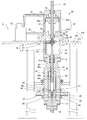
- FIG. 2 is a cross-sectional view of the linear actuator 30 and the reciprocating pump 50 during fuel suction.
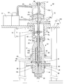
- FIG. 2 is a cross-sectional view of the linear actuator 30 and the reciprocating pump 50 when fuel is discharged.
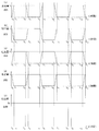
- FIG. (A) is an example of time change of the discharge amount of the fuel supply unit 20A
- (b) is an example of time change of the discharge amount of the fuel supply unit 20B
- (c) is an example of time change of the discharge amount of the fuel supply unit 20C
- D is a figure which shows an example of the time change of the sum total of each discharge amount of fuel supply part 20A, 20B, 20C.
- (A) is an example of the time change of the discharge amount of the fuel supply unit 20A
- (b) is an example of the time change of the discharge amount of the fuel supply unit 20B
- (c) is the fuel supply unit 20A of (a) and (b).
- 20B is a diagram illustrating an example of a temporal change in the total discharge amount of 20B.
- (A) is an example of time change of the discharge amount of the fuel supply unit 20A
- (b) is an example of time change of the discharge amount of the fuel supply unit 20B
- (c) is an example of time change of the discharge amount of the fuel supply unit 20C.
- (D) is an example of the time change of the discharge amount of the fuel supply unit 20D
- (e) is the time change of the total discharge amount of each of the fuel supply units 20A, 20B, 20C, 20D of (a) to (d).
- (A) is an example of time change of the discharge amount of the fuel supply unit 20A
- (b) is an example of time change of the discharge amount of the fuel supply unit 20B
- (c) is an example of time change of the discharge amount of the fuel supply unit 20C
- (D) is a figure which shows an example of the time change of the sum total of each discharge amount of fuel supply part 20A, 20B, 20C of (a)-(c).
- FIG. 6D is a diagram showing another example of the time change of the total discharge amount of each of the fuel supply units 20A, 20B, and 20C.
- (A) is another example of time change of the discharge amount of the fuel supply unit 20A
- (b) is another example of time change of the discharge amount of the fuel supply unit 20B
- (c) is a discharge amount of the fuel supply unit 20C.
- FIG. 6D is a diagram showing another example of the time change of the total discharge amount of each of the fuel supply units 20A, 20B, and 20C.
- FIG. 2 is a view showing a fuel supply unit using an electric cylinder unit as a linear actuator 30.
- FIG. (A), (b), (c) is a figure which shows the example of the time change of the discharge amount of each reciprocating pump when driving three reciprocating pumps using a crankshaft, (d) These are figures which show the time change of the total of the discharge amount of (a), (b), (c).
- the fuel supply device 10 of the present embodiment is a device that pressurizes and heats liquid fuel and injects it into the combustion chamber of the internal combustion engine 90 at a high pressure.
- the internal combustion engine 90 is a prime mover that burns fuel in a combustion chamber in a cylinder and works by its thermal energy, such as a reciprocating engine or a gas turbine.
- a diesel engine that compresses and ignites fuel is preferably used as the internal combustion engine 90.
- a case where a diesel engine mounted on a ship is used as the internal combustion engine 90 will be described.
- the present invention can also be applied to a fuel supply apparatus for a diesel engine other than a ship.
- the fuel supply apparatus 10 includes a liquid fuel tank 11, a low-pressure fuel supply pipe 12, a plurality of fuel supply units 20A, 20B, and 20C, a high-pressure fuel supply pipe 13, and a heat exchanger 14.
- the high-temperature fuel supply pipe 15, the pressure regulating valve 16, the pressure gauge 17, and the control unit 80 are provided. All these components of the fuel supply device 10 are mounted on a ship.
- the liquid fuel tank 11 stores the fuel supplied to the internal combustion engine 90 in a liquid state.
- the liquid fuel stored in the liquid fuel tank 11 for example, liquefied methane, liquefied ethane, liquefied propane, or the like can be used.
- the liquid fuel tank 11 is connected to the low-pressure fuel supply pipe 12 and supplies the liquid fuel to the fuel supply units 20A, 20B, and 20C via the low-pressure fuel supply pipe 12.
- the pressure of the liquid fuel in the low-pressure fuel supply pipe 12 at the connection with the fuel supply units 20A, 20B, and 20C is a pressure corresponding to the liquid level of the liquid fuel in the liquid fuel tank 11.
- the liquid fuel tank 11 is provided by the fuel supply units 20A, 20B, and 20C. Is also placed at a high position. When the liquid fuel tank 11 cannot be disposed at a high position, an effective suction head is secured by increasing the pressure of the liquid fuel in the liquid fuel tank 11 by a booster pump that supplies the liquid fuel to the liquid fuel tank 11. Also good.
- the fuel supply units 20 ⁇ / b> A, 20 ⁇ / b> B, and 20 ⁇ / b> C are provided in parallel between the low pressure fuel supply pipe 12 and the high pressure fuel supply pipe 13.
- Each of the fuel supply units 20A, 20B, and 20C includes a controller 21, a linear actuator 30, and a reciprocating pump 50.
- the reciprocating pump 50 pressurizes the liquid fuel supplied from the low pressure fuel supply pipe 12 and supplies it to the heat exchanger 14 through the high pressure fuel supply pipe 13.
- the low-pressure fuel pipe 12 and the high-pressure fuel supply pipe 13 are detachable from the fuel supply units 20A, 20B, and 20C.
- the linear actuator 30 drives the piston of the reciprocating pump 50.
- the piston of the reciprocating pump 50 is driven at a lower speed than in the case of using the crankshaft.
- the drive can be controlled so that the piston moves at a constant speed.
- a hydraulic cylinder unit, an electric cylinder unit, or the like can be used as the linear actuator 30.
- the controller 21 is controlled by a control signal input from the control unit 80 and controls the linear actuator 30.
- the controller 21 receives a position signal indicating the position of the piston of the reciprocating pump 50, as will be described later.
- the controller 21 controls the position of the linear actuator 30 so that the discharge amount of the reciprocating pump 50 is adjusted according to the position signal.
- three fuel supply units 20A, 20B, and 20C are provided in parallel between the low pressure fuel supply pipe 12 and the high pressure fuel supply pipe 13, but the number of fuel supply parts is not limited thereto. However, it can be arbitrarily changed according to the amount of fuel to be supplied.
- the heat exchanger 14 has an inlet side connected to the high-pressure fuel supply pipe 13 and an outlet side connected to the high-temperature fuel supply pipe 15.
- the heat exchanger 14 heats the pressurized liquid fuel supplied through the high-pressure fuel supply pipe 13.
- a heat source for heating the liquid fuel for example, combustion heat of boil-off gas generated in the liquid fuel tank 11 can be used.
- the liquid fuel may be heated by heat exchange with warm water heated by the combustion heat of boil-off gas.
- the high temperature fuel supply pipe 15 is provided with a pressure regulating valve 16, and one end of the high temperature fuel supply pipe 15 is connected to the heat exchanger 14 and the other end is connected to the combustion chamber of the internal combustion engine 90.
- the liquid fuel heated by the heat exchanger 14 is regulated to a pressure within a predetermined range required by the internal combustion engine 90 by the pressure regulating valve 16, and then is supplied to the combustion chamber of the internal combustion engine 90 through the high temperature fuel supply pipe 15. Supplied.
- the pressure regulating valve 16 is controlled by the control unit 80.
- the pressure in a predetermined range required by the internal combustion engine 90 varies depending on the type and performance of the internal combustion engine 90.
- the pressure in a predetermined range is, for example, 5 to 100 MPa, preferably 20 to 70 MPa, but the present invention is not limited to this.
- the high temperature fuel supply pipe 15 is provided with a pressure gauge 17.
- the pressure gauge 17 measures the pressure in the high temperature fuel supply pipe 15 and outputs a measurement signal to the control unit 80.
- a signal indicating the load on the internal combustion engine 90 is input from the internal combustion engine 90 to the control unit 80.
- the signal indicating the load of the internal combustion engine 90 is a signal indicating the rotational speed, for example.
- the control unit 80 adjusts the discharge amount of the reciprocating pump 50 by outputting a control signal to the fuel supply units 20A, 20B, and 20C.
- the discharge amount of the reciprocating pump 50 is adjusted so that the pressure in the high-temperature fuel supply pipe 15 becomes a pressure corresponding to the required load of the internal combustion engine 90. Note that the number of revolutions of a propulsion propeller (not shown) driven by the internal combustion engine 90 may be measured, and the pressure in the high temperature fuel supply pipe 15 may be adjusted according to the number of revolutions.
- the liquid fuel tank 11, the low-pressure fuel supply pipe 12, the linear actuator 30, the reciprocating pump 50, the high-pressure fuel supply pipe 13, the heat exchanger 14, the high-temperature fuel supply pipe 15, the pressure regulating valve 16, and the pressure gauge 17 are arranged in the hazardous area. Is done.
- the controller 21 and the control unit 80 are generally non-explosion-proof compatible products. However, when the explosion-proof response is not possible, the controller 21 and the control unit 80 are disposed in the non-hazardous area separated from the dangerous area by the explosion-proof partition wall, or are sufficient from the dangerous area. Must be located in a non-explosion-proof area at a distance from each other.
- the linear actuator 30 is not limited to the hydraulic cylinder unit. 2 and 3, the vertical direction coincides with the vertical direction, and the horizontal direction coincides with the horizontal direction.
- the upward direction in the vertical direction is referred to as “upper”, the upper portion is referred to as “upper”, the lower portion in the vertical direction is referred to as “lower”, and the lower portion is referred to as “lower”.
- the linear actuator 30 and the reciprocating pump 50 arranged so that the axial direction is the vertical direction will be described.
- the present invention is not limited to this, and the case where the axial direction is the horizontal direction and the angle
- the linear actuator 30 and the reciprocating pump 50 arranged so as to be in the direction in which they are provided may be used.
- the linear actuator 30 and the reciprocating pump 50 are arranged with the axial direction oriented in the vertical direction. 2 and 3, an example in which the reciprocating pump 50 is disposed below the linear actuator 30 will be described. However, the reciprocating pump 50 may be disposed above the linear actuator 30.
- the hydraulic cylinder unit (linear actuator 30) includes an electric motor 31, a hydraulic pump 32, a first hydraulic pipe 33, a second hydraulic pipe 34, a fixed portion 40, a hydraulic cylinder 41, A hydraulic piston 42 is provided.
- the hydraulic cylinder unit is provided on the top plate 101 of the gantry 100.
- the top plate 101 is supported by legs 102, and the legs 102 are fixed to a structure such as a ship deck or an inner bottom plate.
- the electric motor 31 is provided on the top of the top plate 101.
- the electric motor 31 is controlled by the controller 21 and drives the hydraulic pump 23.
- the hydraulic pump 32 is provided on the top plate 101.
- the hydraulic pump 32 is driven by the electric motor 31 and supplies hydraulic oil into the hydraulic cylinder 41 to move the hydraulic piston 42 in the vertical direction.
- the hydraulic oil any hydraulic oil can be employed from petroleum hydraulic oil, synthetic hydraulic oil, water-forming hydraulic oil and the like.
- the hydraulic pump 32 is connected to the first hydraulic pipe 33 and the second hydraulic pipe 34.
- the hydraulic pump 32 is driven by an electric motor 31.
- the electric motor 31 is a servo motor
- the direction in which the hydraulic oil is discharged from the hydraulic pump 32 is switched according to the forward and reverse rotation directions of the electric motor 31.
- the hydraulic pump 32 sucks the hydraulic oil in the first hydraulic pipe 33 and discharges the sucked hydraulic oil to the second hydraulic pipe 34 side.
- the hydraulic pump 32 sucks the hydraulic oil in the second hydraulic pipe 34 and discharges the sucked hydraulic oil to the first hydraulic pipe 33 side.
- a direction switching valve is not necessary for the first hydraulic pipe 33 and the second hydraulic pipe 34.
- the electric motor 31 is an inverter motor
- the direction in which the hydraulic oil flows is changed by a direction switching valve (not shown) provided in the first hydraulic pipe 33 and the second hydraulic pipe 34.
- the flow rate and pressure of the hydraulic oil in the first hydraulic pipe 33 and the second hydraulic pipe 34 are determined by the discharge amount of the hydraulic pump 32. In both cases where the electric motor 31 is a servo motor and the electric motor 31 is an inverter motor, the flow rate and pressure of hydraulic oil can be adjusted by the electric motor 31.
- the fixing part 40 is fixed to the top plate 101 in a state of being arranged in an opening 101a provided in the top plate 101.
- a hydraulic cylinder 41 is fixed to the upper part of the fixed part 40, and a reciprocating pump 50 is fixed to the lower part of the fixed part 40.
- the fixed part 40 has a hollow cylindrical shape, and a cavity part 48 is provided inside.
- the hydraulic cylinder 41 has a hydraulic oil storage space 43 for storing hydraulic oil, and is placed on the top surface of the top plate 101 so that the axial direction is the vertical direction. Further, an upper through hole 44 that communicates with the upper end portion of the hydraulic oil storage space 43 and a lower through hole 45 that communicates with the lower end portion of the hydraulic oil storage space 43 are provided on the side wall of the hydraulic cylinder 41. The outer opening of the upper through hole 44 is connected to the first hydraulic pipe 33, and the outer opening of the lower through hole 45 is connected to the second hydraulic pipe 34.
- the piston piston 42b is provided in the hydraulic piston 42.
- the hydraulic piston 42 has a piston ring 42b in contact with the inner wall surface of the hydraulic oil storage space 43 of the hydraulic cylinder 41, and the rider ring 42a accommodated in the hydraulic oil storage space 43 is movable in the vertical direction. It plays a role of correcting horizontal shake when moving in the vertical direction.
- the piston ring 42 b serves to close the gap between the hydraulic piston 42 and the inner wall surface of the hydraulic oil storage space 43.
- the hydraulic piston 42 divides the hydraulic oil containing space 43 into an upper chamber 43 a above the hydraulic piston 42 and a lower chamber 43 b below the hydraulic piston 42.
- the hydraulic piston 42 is a double rod type, and has a piston rod 47 that protrudes from the upper and lower portions of the hydraulic cylinder 41 to the outside. The piston rod 47 moves up and down together with the hydraulic piston 42. Since the hydraulic piston 42 is a double rod type, the amount of decrease in the volume of the upper chamber 43a when the hydraulic piston 42 is raised is equal to the amount of increase in the volume of the lower chamber 43b.
- the hydraulic piston 42 may be a single rod type. However, in this case, it is desirable to provide a pulsation prevention tank because pressure fluctuations occur due to changes in the amount of moving hydraulic oil.
- a bush 46 is provided in a portion of the hydraulic cylinder 41 through which the piston rod 47 passes.
- An oil seal is incorporated in the bush 46.
- the bush 46 supports the piston rod 47 so as to be movable up and down, and prevents hydraulic oil from leaking from the hydraulic oil storage space 43.
- a connecting portion 49 for connecting the lower end portion of the piston rod 47 and the upper end portion of the boosting piston 52 of the reciprocating pump 50 is provided in the hollow portion 48.
- the connecting portion 49 moves up and down in the cavity 48 as the piston rod 47 moves up and down.
- the connecting portion 49 has a function of adjusting the axial misalignment between the piston rod 47 of the hydraulic cylinder and the piston 52 of the reciprocating pump 50.
- the room 48 is supplied with nitrogen gas at room temperature from the outside from the viewpoint of preventing gas leakage from the reciprocating pump.
- Nitrogen gas may be supplied to the rod packing portion 57 of the reciprocating pump 50.
- the reciprocating pump 50 for example, a reciprocating pump having the same structure as that described in Japanese Patent No. 5519857 can be used.
- the reciprocating pump 50 includes a boosting cylinder 51, a boosting piston 52, a cylinder liner 53, a cover 54, a valve box 60, and the like.
- the upper end portion of the boosting cylinder 51 is fixed to the lower end portion of the fixing portion 40.
- the side wall of the boosting cylinder 51 is fixed to the legs 102 of the gantry 100.
- a rod packing portion 57 is provided on the upper portion of the boosting cylinder 51.
- the boosting cylinder 51 has a space for accommodating the boosting piston 52, the cylinder liner 53, and the valve box 60 inside, and a cover 54 is fixed to the lower end portion of the boosting cylinder 51.
- the cylinder liner 53 and the valve box 60 are fixed in the boosting cylinder 51 by the cover 54.
- a suction port 55 is provided on the side wall of the boosting cylinder 51 at a height position where the valve box 60 is fixed.
- the suction port 55 is connected to the low pressure fuel supply pipe 12.
- the cover 54 is provided with a discharge port 56 penetrating in the vertical direction.
- the discharge port 56 is connected to the high-pressure fuel supply pipe 13.
- the valve box 60 is provided below the boosting piston 52, and when the boosting piston 52 is moved vertically upward, the fuel is placed inside the boosting cylinder 51 and below the boosting piston 52.
- the suction port 55 of the reciprocating pump 50 can be arranged at a lower position.
- the pressure of the liquid fuel in the low-pressure fuel supply pipe 12 at the connection portion with the suction port 55 is a pressure proportional to the difference between the height of the liquid fuel level in the liquid fuel tank 11 and the height of the suction port 55. For this reason, the pressure of the liquid fuel in the low-pressure fuel supply pipe 12 at the connection portion with the suction port 55 can be increased by arranging the suction port 55 at a lower position. As a result, fuel can be easily supplied from the suction port 55 into the pressure-increasing cylinder 51.
- the upper end of the boosting piston 52 is connected to the lower end of the piston rod 47 by a connecting portion 49, and the boosting piston 52 moves up and down in conjunction with the piston rod 47.
- a position sensor is provided at the upper end of the boosting piston 52. The position sensor detects the position of the boosting piston 52 in the vertical direction and outputs a position signal to the controller 21. Note that the speed of the boosting piston 52 can be obtained by differentiating the displacement of the boosting piston 52 with time using the position signal. That is, the position sensor can also be used as a speed sensor.
- a position sensor may be attached to the hydraulic cylinder 41.
- the magnetostrictive position sensor 70 for example, a magnetostrictive position sensor 70 or an ultrasonic sensor can be used.
- the magnetostrictive position sensor 70 includes a sensor probe 71 (magnetostrictive line), an annular magnet 72, and a detector 73.
- the sensor probe 71 is provided in the cavity 48 in the vertical direction.
- the annular magnet 72 is attached to the upper end of the boosting piston 52 so as to move up and down along with the boosting piston 52 along the sensor probe 71 with the sensor probe 71 inserted in the center.
- One end of the sensor probe 71 is provided with a detector 73 that detects distortion generated in the sensor probe 71.
- a magnetic field in the circumferential direction around the sensor probe 71 is generated.
- a magnetic field is applied in the axial direction of the sensor probe 71, so that a combined magnetic field oblique to the axial direction is generated.
- This causes local torsional distortion in the sensor probe 71.
- the detector 73 detects the torsional distortion to detect the position of the magnet 72 in the height direction, and outputs a position signal indicating the position of the boosting piston 52 in the height direction to the controller 21.
- a rider ring 52a and a piston ring 52b are provided below the boosting piston 52.
- the boosting piston 52 is accommodated in the cylinder liner 53 so as to be movable in the vertical direction while bringing the rider ring 52a and the piston ring 52b into contact with the inner wall surface of the cylinder liner 53.
- the rod packing portion 57 is also equipped with a rider ring 51a. These rider rings 51a and 52a play a role of correcting horizontal shake when the boosting piston 52 moves in the vertical direction.
- the piston ring 52b serves to close the gap between the boosting piston 52 and the inner wall surface of the cylinder liner 53 and seal the pressure of the pressurized liquid fuel at the tip.
- the valve box 60 is fixed to the lower portion of the cylinder liner 53 in the boosting cylinder 51.
- the valve box 60 is provided with a discharge flow path 61, a discharge valve body 62, a suction flow path 64, a suction valve body 65, and the like.
- the discharge flow path 61 is provided so as to penetrate the valve box 60 in the vertical direction.
- a discharge valve element 62 is accommodated in the discharge flow path 61 so as to be movable in the vertical direction.
- the upper end portion side of the discharge channel 61 is a small diameter portion whose inner diameter is smaller than the outer diameter of the discharge valve body 62.
- the lower opening of the narrow diameter portion is a valve seat 63 in which the discharge valve body 62 is disposed.
- the discharge valve element 62 and the valve seat 63 constitute a discharge valve.
- An opening on the lower side of the valve box 60 of the discharge channel 61 is provided at a position facing the discharge port 56 of the cover 54.
- the suction flow path 64 is provided at a position communicating with the position of the boosting piston 52 on the upper surface of the valve box 60 from the outer wall of the valve box 60.
- the opening on the outer wall side of the valve box 60 of the suction flow path 64 is provided at a position facing the suction port 55 of the boosting cylinder 51.
- the outer peripheral portion of the opening on the upper surface side of the valve box 60 of the suction flow path 64 is a valve seat 66 for the suction valve body 65, and the suction valve body 65 can move in the vertical direction above the valve seat 66. Is provided.
- the suction valve element 65 and the valve seat 66 constitute a suction valve.
- the rod packing part 57 is connected to the cavity part 48 and is equipped with a seal ring so as to prevent the gas vaporized by the liquid fuel from leaking to the outside air.
- the leaked liquid fuel that cannot be sealed by the piston ring 52 b is vaporized under a low pressure and is sealed by the rod packing portion 57.
- nitrogen gas may be supplied to the rod packing portion 57 instead of supplying it to the cavity portion 48.
- the rotation direction of the electric motor 31 is switched by the controller 21 and the hydraulic pump 32 is driven in the direction opposite to that in FIG. 2, and the hydraulic oil in the lower chamber 43 b is sent to the lower through hole 45 as shown in FIG. 3. And is supplied from the upper through hole 44 to the upper chamber 43a through the second hydraulic pipe 34 and the first hydraulic pipe 33.
- the hydraulic piston 42 descends in the hydraulic oil storage space 43 so that the volume of the lower chamber 43b decreases and the volume of the upper chamber 43a increases. Since the first hydraulic pipe 33 and the second hydraulic pipe do not have a branch or the like, all the hydraulic oil flowing out from the lower chamber 43b is supplied to the upper chamber 43a.
- the boosting piston 52 connected to the lower end portion of the piston rod 47 at the connecting portion 49 is lowered in the cylinder liner 53 (moves in the second direction). Then, the liquid fuel sucked into the space inside the cylinder liner 53 and below the boosting piston 52 pushes the discharge valve body 62 away from the valve seat 63 and is discharged from the discharge port 56. At this time, the suction valve body 65 is in a state of closing the valve seat 66.
- the hydraulic oil is alternately passed between the upper chamber 43a and the lower chamber 43b, and the hydraulic piston 42 and the booster pump are increased.
- the piston 52 can be reciprocated in the vertical direction, and the liquid fuel sucked from the suction port 55 can be pressurized and discharged from the discharge port 56.
- the hydraulic oil is alternately moved between the upper chamber 43a and the lower chamber 43b by switching the flow direction of the hydraulic oil by the direction switching valve.
- the hydraulic piston 42 and the boosting piston 52 are reciprocated in the vertical direction, and the liquid fuel sucked from the suction port 55 can be boosted and discharged from the discharge port 56.
- control unit 80 controls the fuel supply units 20A, 20B, and 20C so that the total amount of fuel discharged from the boost cylinders 51 of the fuel supply units 20A, 20B, and 20C is constant.
- the respective controllers 21 are preferably controlled.
- control unit 90 when the amount of fuel discharged from at least one of the fuel supply units 20A, 20B, and 20C increases, the control unit 90 is configured so that the amount of fuel discharged from the other fuel supply units decreases. What is necessary is just to control several fuel supply part 20A, 20B, 20C.
- the control unit 90 may control the plurality of fuel supply units 20A, 20B, and 20C.
- the discharge amount of each of the fuel supply units 20A, 20B, and 20C is the product of the cross-sectional area and speed of the boosting piston 52. Therefore, the controller 21 controls the linear actuator 30 to adjust the speed of the boosting piston 52, that is, to adjust the oil pressure by adjusting the amount of oil flowing into the hydraulic cylinder 41, thereby supplying fuel.
- Each discharge amount of the sections 20A, 20B, and 20C can be adjusted.
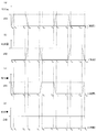
- FIG. 4A is a diagram illustrating an example of a change over time in the discharge amount of the fuel supply unit 20A
- FIG. 4B is a diagram illustrating an example of a change over time in the discharge amount of the fuel supply unit 20B
- FIG. 4C is a diagram showing an example of a change over time in the discharge amount of the fuel supply unit 20C
- FIG. 4D is a discharge of each of the fuel supply units 20A, 20B, and 20C of FIGS. 4A to 4C. It is a figure which shows an example of the time change of the total of quantity.
- the boosting pistons of the fuel supply units 20A, 20B, and 20C reciprocate at the same cycle.
- FIG. 4A As shown in FIG. 4A, at time t0, acceleration of the boosting piston 52 in the second direction is started in the fuel supply unit 20A, and at the same time, the second direction of the boosting piston 52 in the fuel supply unit 20C. Start slowing down. From time t0 to t1, the discharge amount per unit time of the fuel supply unit 20A increases as shown in FIG. 4 (a), and at the same time, as shown in FIG. 4 (c), per unit time of the fuel supply unit 20C. The amount of discharge decreases. As shown in FIG. 4B, the discharge amount of the fuel supply unit 20B is zero.
- the total discharge amount per unit time is constant as shown in FIG. Become.
- the acceleration of the boosting piston 52 in the second direction is completed in the fuel supply unit 20A, and at the same time, the deceleration of the boosting piston 52 in the second direction is completed in the fuel supply unit 20C.
- the discharge amount per unit time of the fuel supply unit 20A is constant, and the discharge amounts per unit time of the other fuel supply units 20B and 20C are zero. As shown, the total amount of discharge per unit time is constant.
- the fuel supply unit 20A starts decelerating the boosting piston 52 in the second direction, and at the same time, the fuel supply unit 20B starts accelerating the boosting piston 52 in the second direction.
- the discharge amount per unit time of the fuel supply unit 20B increases, and at the same time, as shown in FIG. 4A, per unit time of the fuel supply unit 20A.
- the amount of discharge decreases.
- the discharge amount per unit time of the fuel supply unit 20C is zero. At this time, since the increase amount of the discharge amount per unit time of the fuel supply unit 20B is equal to the decrease amount of the discharge amount per unit time of the fuel supply unit 20A, as shown in FIG.
- the total discharge amount is constant.
- the fuel supply unit 20A completes the deceleration of the boosting piston 52 in the second direction, and at the same time, the fuel supply unit 20B ends the acceleration of the boosting piston 52 in the second direction.
- the discharge amount per unit time of the fuel supply unit 20B is constant, and the discharge amounts per unit time of the other fuel supply units 20A and 20C are zero. As shown, the total amount of discharge per unit time is constant.
- the discharge amount per unit time of the fuel supply unit 20C increases, and at the same time, per unit time of the fuel supply unit 20B as shown in FIG. 4B.
- the amount of discharge decreases.
- the discharge amount per unit time of the fuel supply unit 20A is zero.
- the discharge amount per unit time of the fuel supply unit 20C is constant, and the discharge amounts per unit time of the other fuel supply units 20A and 20B are zero. As shown, the total amount of discharge per unit time is constant.
- control unit 80 controls the fuel supply units 20A, 20B so that the sum of the discharge amounts per unit time of the fuel discharged from the boost cylinders 51 of the fuel supply units 20A, 20B, 20C is constant.
- 20C can be controlled to prevent pulsation from occurring in the high-pressure fuel supply pipe 13. Note that if the maximum discharge amount of the fuel supply units 20A, 20B, and 20C is v, the total discharge amount per unit time is constant at v.
- the stroke is the height from the lowest point to the highest point when the boosting piston 52 reciprocates in the vertical direction.
- the stroke is set based on the position of the lowermost portion of the boosting piston 52 in the cylinder liner 53.
- the lowermost position of the boosting piston 52 is a position in the cylinder liner 53 where the volume of the space below the boosting piston 52 is minimized. Regardless of how the stroke is set by adjusting the stroke based on this position, all the liquid fuel in the reciprocating pump 50 is discharged in each cycle.
- the time interval between t (n ⁇ 1) and tn (n is a natural number) is shown as an equal interval, but the time interval can be changed as appropriate.
- the time interval between t1 and t2 may be increased by decreasing the discharge amount per time, that is, the speed of the boosting piston 52. Since the reciprocating pump 50 is driven using the linear actuator 30, the stroke of the boosting piston 52 can be freely adjusted.
- the controller 21 controls the drive of the linear actuator 30 so that the speed at which the boosting piston 52 descends (speed that moves in the second direction) is constant so that the discharge amount of the reciprocating pump 50 is constant. May be.
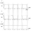
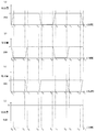
- FIG. 5 is a diagram illustrating an example of a change over time in the discharge amount when fuel is supplied only by the fuel supply units 20A and 20B.
- FIG. 5A illustrates an example of a change over time in the discharge amount of the fuel supply unit 20A.
- FIG. 5B is a diagram illustrating an example of a change over time in the discharge amount of the fuel supply unit 20B.
- FIG. 5C is a diagram illustrating the fuel supply units 20A and 20B in FIGS. 5A and 5B. It is a figure which shows an example of the time change of the total of each discharge amount.
- the discharge amount of the fuel supply unit 20A increases as shown in FIG. 5A, and at the same time, the discharge amount of the fuel supply unit 20B decreases as shown in FIG. 5B.
- the total discharge amount is constant as shown in FIG. From time t1 to t2, since the discharge amount of the fuel supply unit 20A is constant and the discharge amount of the fuel supply unit 20B is zero, the total discharge amount is constant as shown in FIG. 5C. .
- the discharge amount of the fuel supply unit 20B increases, and at the same time, the discharge amount of the fuel supply unit 20A decreases as shown in FIG. 5 (a).
- the total discharge amount is constant as shown in FIG. From time t3 to t4, since the discharge amount of the fuel supply unit 20B is constant and the discharge amount of the fuel supply unit 20A is zero, the total discharge amount is constant as shown in FIG. 5C. .
- the total discharge amount can be made constant by shifting the discharge timing of the fuel supply units 20A and 20B.
- FIG. 6 is a diagram showing an example of the change over time in the discharge amount when fuel is supplied from the four fuel supply units 20A, 20B, 20C, and 20D.
- FIG. 6A shows the discharge amount time of the fuel supply unit 20A.
- FIG. 6B is a diagram illustrating an example of a change in the discharge amount of the fuel supply unit 20B
- FIG. 6C is a diagram illustrating a change in the discharge amount of the fuel supply unit 20C over time.
- FIG. 6 (d) is a diagram showing an example of a temporal change in the discharge amount of the fuel supply unit 20D
- FIG. 6 (e) is a diagram of the fuel supply unit shown in FIGS. 6 (a) to 6 (d). It is a figure which shows an example of the time change of the total of each discharge amount of 20A, 20B, 20C, 20D.
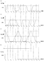
- FIG. 7A is a diagram showing an example of the change over time of the discharge amount of the fuel supply unit 20A
- FIG. 7B is a diagram showing an example of the change over time of the discharge amount of the fuel supply unit 20B
- FIG. 7C is a diagram showing an example of the change over time in the discharge amount of the fuel supply unit 20C
- FIG. 7D is the discharge of each of the fuel supply units 20A, 20B, and 20C of FIGS. It is a figure which shows an example of the time change of the total of quantity.
- the maximum discharge amount of the fuel supply unit 20B is v1
- the maximum discharge amount of the fuel supply unit 20C is v2
- the maximum discharge amount of the fuel supply unit 20A is v1 + v2 and each of the fuel supply units 20A, 20B, and 20C.
- the speed of the boosting piston 52 is adjusted so that the total discharge amount becomes v1 + v2.
- v1 and v2 may be different or the same.
- the discharge amount of the fuel supply unit 20A increases as shown in FIG. 7 (a), and at the same time, the discharge of the fuel supply units 20B and 20C, as shown in FIGS. 7 (b) and 7 (c). The amount decreases.
- the increase amount of the discharge amount of the fuel supply unit 20A is equal to the sum of the decrease amounts of the discharge amounts of the fuel supply units 20B and 20C, the total discharge amount is constant as shown in FIG. Become. From time t1 to t2, since the discharge amount of the fuel supply unit 20A is constant (v1 + v2) and the discharge amounts of the fuel supply units 20B and 20C are zero, as shown in FIG. The sum is constant (v1 + v2).
- the discharge amount of the fuel supply units 20B and 20C increases, and at the same time, the discharge of the fuel supply unit 20A as shown in FIG. 7A. The amount decreases.
- the total discharge amount is constant as shown in FIG. Become.
- the discharge amount of the fuel supply unit 20B is constant at v1
- the discharge amount of the fuel supply unit 20C is constant at v2
- the discharge amount of the fuel supply unit 20A is zero.
- the total discharge amount is constant (v1 + v2).
- FIG. 8A is a diagram showing another example of the temporal change in the discharge amount of the fuel supply unit 20A
- FIG. 8B is a diagram showing another example of the temporal change in the discharge amount of the fuel supply unit 20B.
- FIG. 8 (c) is a diagram showing another example of the change over time in the discharge amount of the fuel supply unit 20C
- FIG. 8 (d) shows the fuel supply units 20A and 20B of FIGS. 8 (a) to (c).
- 20C is a diagram illustrating an example of a temporal change in the total discharge amount of 20C.
- the discharge amount of the fuel supply unit 20A increases as shown in FIG. 8A, and at the same time, the discharge amount of the fuel supply unit 20B decreases as shown in FIG. 8B.
- the discharge amount of the fuel supply unit 20C is constant.
- the total discharge amount is constant as shown in FIG. From time t1 to t2, the discharge amount of the fuel supply units 20A and 20C is constant, and the discharge amount of the fuel supply unit 20B is zero. Therefore, as shown in FIG. 8D, the total discharge amount is constant. It becomes.
- the discharge amount of the fuel supply unit 20B increases, and at the same time, the discharge amount of the fuel supply unit 20C decreases as shown in FIG. 8C.
- the discharge amount of the fuel supply unit 20A is constant.
- the total discharge amount is constant as shown in FIG. From time t3 to t4, the discharge amount of the fuel supply units 20A and 20B is constant, and the discharge amount of the fuel supply unit 20C is zero. Therefore, as shown in FIG. 8D, the total discharge amount is constant. It becomes.
- the discharge amount of the fuel supply unit 20C increases, and at the same time, the discharge amount of the fuel supply unit 20B decreases as shown in FIG. 8B.
- the discharge amount of the fuel supply unit 20A is zero.
- the total discharge amount is constant as shown in FIG. From time t5 to t6, the discharge amount of the fuel supply units 20B and 20C is constant, and the discharge amount of the fuel supply unit 20A is zero. Therefore, as shown in FIG. 8D, the total discharge amount is constant. It becomes.
- the total amount of fuel discharged from the boost cylinders 51 of the fuel supply units 20A, 20B, and 20C is constant.
- the control unit 80 controls each of the controllers 21 of the fuel supply units 20A, 20B, and 20C, thereby preventing pulsation from occurring in the high-pressure fuel supply pipe 13. Note that if the maximum value of the discharge amount of the fuel supply units 20A, 20B, and 20C is v, the total discharge amount is constant at 2v.
- the time interval between t (n ⁇ 1) and tn (n is a natural number) can be changed as appropriate. For example, by increasing the stroke of the boosting piston 52, the time interval between t (n ⁇ 1) and tn is increased while keeping the speed of the boosting piston 52 constant (while keeping the discharge amount constant). Also good.
- the time from t1 to t2 may be twice as long as the time from t3 to t4 or the time from t5 to t6.
- the discharge amount waveforms of the fuel supply units 20A, 20B, and 20C are the same and have different phases. However, the discharge amount waveforms of the fuel supply units 20A, 20B, and 20C may be different. Alternatively, the maximum discharge amount of the fuel supply units 20A, 20B, and 20C may be different.
- FIG. 9A is a diagram showing another example of the temporal change in the discharge amount of the fuel supply unit 20A
- FIG. 9B is a diagram showing another example of the temporal change in the discharge amount of the fuel supply unit 20B
- FIG. 9C is a diagram showing another example of the temporal change of the discharge amount of the fuel supply unit 20C
- FIG. 9D is a diagram of the fuel supply units 20A and 20B of FIGS. 9A to 9C.
- 20C is a diagram illustrating an example of a temporal change in the total discharge amount of 20C.
- the discharge amount of the fuel supply unit 20A increases as shown in FIG. 9A, and at the same time, the discharge amount of the fuel supply unit 20C decreases as shown in FIG. 9C.
- the discharge amount of the fuel supply unit 20B is zero.
- the total discharge amount is constant as shown in FIG.
- the discharge amount of the fuel supply unit 20B increases, and at the same time, the discharge amount of the fuel supply unit 20C decreases as shown in FIG. 9C.
- the discharge amount of the fuel supply unit 20A is constant.
- the total discharge amount is constant as shown in FIG.
- the total amount of fuel discharged from the boost cylinders 51 of the fuel supply units 20A, 20B, and 20C is constant.
- the control unit 80 controls each of the controllers 21 of the fuel supply units 20A, 20B, and 20C, thereby preventing pulsation from occurring in the high-pressure fuel supply pipe 13. If the maximum discharge amount of the fuel supply units 20A and 20B is v and the maximum discharge amount of the fuel supply unit 20C is 2v, the total discharge amount is constant at 2v.
- the fuel supply units 20A, 20B and the fuel supply unit 20C have different stroke lengths and speeds of the boosting piston 52, and the discharge timings of the fuel supply units 20A, 20B, 20C are shifted, thereby reducing the discharge amount.
- the sum can be constant.
- the moving direction of the hydraulic piston 42 can be switched by switching the flow direction of the hydraulic oil supplied into the hydraulic cylinder 41 according to the forward / reverse rotation direction of the hydraulic pump 32.
- the flow direction of the hydraulic oil is not switched by the direction switching valve, it is not necessary to continue the operation of the hydraulic pump 32 at the rated rotational speed, and energy is compared with the case where the hydraulic pump 32 is continuously operated at the rated rotational speed. Consumption can be reduced.
- the plurality of fuel supply units 20A, 20B, and 20C are provided in parallel between the low pressure fuel supply pipe 12 and the high pressure fuel supply pipe 13, the number of fuel supply parts can be easily changed. Further, even when trouble occurs in any of the plurality of fuel supply units or when maintenance is performed, any one of the fuel supply units can be removed and the other fuel supply units can be continuously driven.
- the speed and position of the boosting piston 52 can be adjusted reliably.
- the present invention is not limited to this, and an arbitrary number of fuel supply units can be used.
- an auxiliary fuel supply unit may be further provided in addition to the three fuel supply units 20A, 20B, and 20C.
- the discharge amount decreases when the total discharge amount from the three fuel supply units 20A, 20B, and 20C decreases for some reason.
- the fuel may be discharged from an auxiliary fuel supply unit so as to supplement the amount.
- the shape of the reciprocating pump 50 is not limited to the shape shown in FIGS.
- the linear actuator 30 and the reciprocating pump 50 can be installed on an arbitrary structure.
- the linear actuator 30 and the reciprocating pump 50 may be mounted on the body of an automobile, or the linear actuator 30 and the reciprocating pump 50 may be installed on the floor of a building frame.
- FIG. 10 is a view showing a fuel supply unit using the electric cylinder unit as the linear actuator 30.
- the electric cylinder unit includes an electric motor 31, gears 35 a and 35 b, a ball nut 37, and a ball screw 38.
- the gear 35a is rotated by the power of the electric motor 31, and the rotation of the gear 35a is transmitted to the gear 35b.
- the gear 35 b is provided integrally with the ball nut 37 and transmits the rotation of the gear 35 a to the ball nut 37.
- the ball nut 37 is screwed with the ball screw 38 and rotates together with the gear 35b.
- the lower end of the ball screw 38 is connected to the upper end of the boosting piston 52 by a connecting portion 49.
- the ball screw 38 moves in the axial direction.
- the boosting piston 52 also moves in the axial direction.
- the same effect as the case where a hydraulic cylinder unit is used as the linear actuator 30 can be obtained.
- the rotation of the electric motor 31 may be transmitted to the ball nut using a pulley and a timing belt instead of the gears 35a and 35b. .
- Fuel supply apparatus 11 Liquid fuel tank 12 Low pressure fuel supply pipe 13 High pressure fuel supply pipe 14 Heat exchanger 15 High temperature fuel supply pipe 16 Pressure regulation valve 17 Pressure gauge 20A, 20B, 20C Fuel supply part 21 Controller 30 Linear actuator 31 Electric motor 32 Hydraulic pump 33 First hydraulic pipe 34 Second hydraulic pipe 35a, 35b Gear 37 Ball nut 38 Ball screw 41 Hydraulic cylinder 42 Hydraulic piston 42b, 52b Piston ring 43 Working oil storage space 43a Upper chamber 43b Lower chamber 47 Piston rod 48 Heat insulating cavity 49 Connection 50 Reciprocating pump 51 Boosting cylinder 51a, 52a Rider ring 52 Boosting piston 53 Cylinder liner 54 Cover 55 Suction port 56 Discharge port 57 Rod packing 60 Valve box 61 Discharge Passage 62 discharge valve body 63, 66 valve seat 64 intake passage 65 suction valve element 70 position sensor 80 control unit 90 engine
Landscapes
- Engineering & Computer Science (AREA)
- Mechanical Engineering (AREA)
- General Engineering & Computer Science (AREA)
- Chemical & Material Sciences (AREA)
- Combustion & Propulsion (AREA)
- Chemical Kinetics & Catalysis (AREA)
- General Chemical & Material Sciences (AREA)
- Oil, Petroleum & Natural Gas (AREA)
- Reciprocating Pumps (AREA)
- Fuel-Injection Apparatus (AREA)
- Control Of Positive-Displacement Pumps (AREA)
- Details Of Reciprocating Pumps (AREA)
Abstract
Description
近年、低速ディーゼルエンジンの燃料として、NOx、SOx排出量の少ない天然ガスが注目されている。低速ディーゼルエンジンの燃焼室に高圧の天然ガスを燃料として噴射して燃焼させることで、高熱効率で出力が得られる。
図11(a)、(b)、(c)はクランク軸を用いて3台の往復式ポンプを駆動する場合のそれぞれの往復式ポンプの吐出量の時間変化の例を示す図であり、図7(d)は(a)、(b)、(c)の吐出量の合計の時間変化を示す図である。クランク軸の回転運動がピストンの直進運動に変換されるため、各ピストンは正弦波状に移動し、それぞれの往復式ポンプの吐出量の時間変化もまた正弦波状となる。3台の往復式ポンプによる吐出タイミングを1/3周期ずつずらすことで、図11(d)に示すように、吐出量の合計の時間変化は少なくなるものの、完全には時間変化が消失することはなく、脈動の原因となっていた。また回転数を低下させると、吐出量の波形の振幅は徐々に低くなるものの、吐出量の合計の時間変化が完全に消失することはない。
特許文献1には、ピストンが一定の速度で移動するようにピストン行程を制御することで、圧力パルスの発生を低減することが記載されている。しかし、特許文献1の装置では、往復式ポンプの下流側では燃料の吐出時に吸入時と比較して圧力が上昇するため、ピストンの往復サイクルに応じた脈動が生じるという問題がある。
低圧の燃料が供給される低圧燃料供給管と、
前記燃焼室内へ供給される高圧の燃料が供給される高圧燃料供給管と、
前記低圧燃料供給管と前記高圧燃料供給管との間に設けられ、それぞれ前記低圧燃料供給管内の燃料を吸入し昇圧して前記高圧燃料供給管に供給する複数の燃料供給部と、
前記複数の燃料供給部を制御する制御部と、
を備え、
前記燃料供給部のそれぞれは、
リニアアクチュエータと、
前記リニアアクチュエータによって駆動され軸方向に往復する昇圧用ピストンを有し、前記昇圧用ピストンが軸方向の第1の方向に移動したときに前記燃料を吸入し、前記昇圧用ピストンが軸方向の第2の方向に移動したときに前記燃料を昇圧して吐出する往復式ポンプと、
前記制御部により制御され、前記リニアアクチュエータの駆動を制御するコントローラと、
を備え、
前記制御部は、前記それぞれの昇圧用ピストンが同一の周期で往復し、かつ、
少なくとも1つの燃料供給部において昇圧用ピストンが1往復する間に第2の方向への移動速度が加速することで燃料の単位時間当たりの吐出量が増加する間に、他の燃料供給部において昇圧用ピストンの第2の方向への移動速度が減速することで燃料の単位時間当たりの吐出量が減少することで、前記複数の燃料供給部のそれぞれから吐出される燃料の単位時間当たりの吐出量の和が一定値となるように、
前記1つの燃料供給部において昇圧用ピストンの第2の方向への加速を開始するときに少なくとも1つの他の燃料供給部において昇圧用ピストンの第2の方向への減速を開始し、
前記1つの燃料供給部において昇圧用ピストンの第2の方向への加速を終了するときに少なくとも1つの他の燃料供給部において昇圧用ピストンの第2の方向への減速を終了するとともに、
前記1つの燃料供給部において昇圧用ピストンが1往復する間に第2の方向への移動速度が減速することで燃料の単位時間当たりの吐出量が減少する間に、他の燃料供給部において昇圧用ピストンの第2の方向への移動速度が加速することで燃料の単位時間当たりの吐出量が増加することで、前記複数の燃料供給部のそれぞれから吐出される燃料の単位時間当たりの吐出量の和が一定値となるように、
前記1つの燃料供給部において昇圧用ピストンの第2の方向への減速を開始するときに少なくとも1つの他の燃料供給部において昇圧用ピストンの第2の方向への加速を開始し、
前記1つの燃料供給部において昇圧用ピストンの第2の方向への減速を終了するときに少なくとも1つの他の燃料供給部において昇圧用ピストンの第2の方向への加速を終了するように、前記複数の燃料供給部を制御する、ことを特徴とする。
作動油を収容する作動油収容空間を有し、軸方向が前記昇圧用ピストンの軸方向と一致するように配置された油圧シリンダと、
前記油圧シリンダ内で軸方向に移動可能に設けられ、前記作動油収容空間を第1チャンバと第2チャンバとに区画する油圧ピストンと、
前記油圧ピストンと前記昇圧用ピストンとを連結するピストンロッドと、
前記第1チャンバに作動油を供給することで前記油圧ピストンを軸方向の第1の方向に移動させ、前記第2チャンバに作動油を供給することで前記油圧ピストンを軸方向の第2の方向に移動させる油圧ポンプと、
前記油圧ピストンが軸方向に往復するように前記油圧ポンプを駆動する電動モータとを備え、
前記コントローラは、前記電動モータを制御することで前記油圧ピストンの前記油圧シリンダ内での移動を制御する、ことが好ましい。
一端が前記油圧ポンプと接続され、他端が前記第1チャンバと接続され、前記油圧ポンプから吐出される全ての作動油を前記第1チャンバに供給し、前記第1チャンバから排出される全ての作動油を前記油圧ポンプに戻す密閉された第1の油圧配管と、
一端が前記油圧ポンプと接続され、他端が前記第2チャンバと接続され、前記第1チャンバから排出される作動油と同量の作動油を前記第2チャンバに供給し、前記第1チャンバに供給される作動油と同量の作動油を前記第2チャンバから排出する密閉された第2の油圧配管と、
をさらに備える、ことが好ましい。
前記ピストンロッドの前記第1チャンバにおける長さ方向と垂直な断面積は、前記ピストンロッドの前記第2チャンバにおける長さ方向と垂直な断面積と等しい、ことが好ましい。
電動シリンダユニットは、電動モータと、
前記電動モータの動力により回転するボールナットと、
前記ボールナットが螺合し、軸方向が前記昇圧用ピストンの軸方向と一致した状態で前記昇圧用ピストンと連結され、前記ボールナットの回転により軸方向に移動するボールねじと、
を備え、
前記コントローラは、前記電動モータを制御することで前記ボールねじの軸方向の移動を制御する、ことが好ましい。
低圧の燃料が供給される低圧燃料供給管と、前記燃焼室内へ供給される高圧の燃料が供給される高圧燃料供給管と、の間に設けられた複数の燃料供給部により、前記低圧燃料供給管内の燃料を吸入し昇圧して前記高圧燃料供給管に供給し、
前記燃料供給部のそれぞれは、軸方向に往復する昇圧用ピストンを有し、前記昇圧用ピストンが軸方向の第1の方向に移動したときに前記燃料を吸入し、前記昇圧用ピストンが軸方向の第2の方向に移動したときに前記燃料を昇圧して吐出する往復式ポンプを有し、
前記それぞれの昇圧用ピストンを同一の周期で往復させ、かつ、
少なくとも1つの燃料供給部において昇圧用ピストンが1往復する間に第2の方向への移動速度を加速させることで燃料の単位時間当たりの吐出量を増加させる間に、他の燃料供給部において昇圧用ピストンの第2の方向への移動速度を減速させることで燃料の単位時間当たりの吐出量を減少させることで、前記複数の燃料供給部のそれぞれから吐出される燃料の単位時間当たりの吐出量の和が一定値となるように、
前記1つの燃料供給部において昇圧用ピストンの第2の方向への加速を開始するときに少なくとも1つの他の燃料供給部において昇圧用ピストンの第2の方向への減速を開始し、
前記1つの燃料供給部において昇圧用ピストンの第2の方向への加速を終了するときに少なくとも1つの他の燃料供給部において昇圧用ピストンの第2の方向への減速を終了するとともに、
前記1つの燃料供給部において昇圧用ピストンが1往復する間に第2の方向への移動速度が減速することで燃料の単位時間当たりの吐出量が減少する間に、他の燃料供給部において昇圧用ピストンの第2の方向への移動速度が加速することで燃料の単位時間当たりの吐出量が増加することで、前記複数の燃料供給部のそれぞれから吐出される燃料の単位時間当たりの吐出量の和が一定値となるように、
前記1つの燃料供給部において昇圧用ピストンの第2の方向への減速を開始するときに少なくとも1つの他の燃料供給部において昇圧用ピストンの第2の方向への加速を開始し、
前記1つの燃料供給部において昇圧用ピストンの第2の方向への減速を終了するときに少なくとも1つの他の燃料供給部において昇圧用ピストンの第2の方向への加速を終了するように、前記複数の燃料供給部を制御する、ことを特徴とする。
図1に示すように、本実施形態の燃料供給装置10は、液体燃料を昇圧・加熱し、内燃機関90の燃焼室内へ高圧で噴射して供給する装置である。内燃機関90はシリンダ内の燃焼室で燃料を燃焼させ、その熱エネルギーによって仕事をする原動機であり、例えばレシプロエンジン、ガスタービンである。特に、燃料を圧縮着火させるディーゼルエンジンを内燃機関90として用いることが好ましい。以下の実施形態では、内燃機関90として船舶に搭載されるディーゼルエンジンを用いる場合について説明するが、本発明は船舶以外のディーゼルエンジンへの燃料供給装置に適用することもできる。
燃料供給部20A、20B、20Cとの接続部における低圧燃料供給管12内の液体燃料の圧力は、液体燃料タンク11内の液体燃料の液面の高さに応じた圧力となっている。この圧力を高め有効吸込みヘッド(NPSH:Net Positive Suction Head)を確保し、燃料供給部20A、20B,20Cに供給しやすくするために、液体燃料タンク11は、燃料供給部20A、20B、20Cよりも高い位置に配置されている。
なお、液体燃料タンク11が高い位置に配置できない場合は、液体燃料タンク11に液体燃料を供給するブースターポンプにより液体燃料タンク11内の液体燃料の圧力を高めることで、有効吸込ヘッドを確保してもよい。
往復式ポンプ50は、低圧燃料供給管12から供給される液体燃料を昇圧し、高圧燃料供給管13を介して熱交換器14に供給する。低圧燃料管12および高圧燃料供給管13は、燃料供給部20A、20B、20Cから着脱可能である。
コントローラ21は、制御部80から入力される制御信号により制御され、リニアアクチュエータ30を制御する。また、コントローラ21には、後述するように、往復式ポンプ50のピストンの位置を示す位置信号が入力される。コントローラ21は、位置信号に応じて往復式ポンプ50の吐出量が調節されるようにリニアアクチュエータ30を位置制御する。
ここで、内燃機関90が必要とする所定の範囲の圧力は、内燃機関90の種類や性能に応じて異なる。内燃機関90が船舶用の2ストロークサイクルの低速ディーゼルエンジンであれば、所定の範囲の圧力は、例えば5~100MPa、好ましくは20~70MPaであるが、本発明はこれに限定されるものではない。
また、高温燃料供給管15には、圧力計17が設けられている。圧力計17は高温燃料供給管15内の圧力を計測し、計測信号を制御部80に出力する。
制御部80は、燃料供給部20A、20B、20Cに制御信号を出力することで、往復式ポンプ50の吐出量を調整する。往復式ポンプ50の吐出量は、高温燃料供給管15内の圧力が、必要とされる内燃機関90の負荷に応じた圧力となるように調整される。
なお、内燃機関90により駆動される推進用プロペラ(図示せず)の回転数を計測し、回転数に応じて高温燃料供給管15内の圧力を調整してもよい。
図2、図3において、上下方向は鉛直方向と一致し、左右方向は水平方向と一致する。以下の説明では、鉛直方向の上方向を「上方」、上方の部分を「上部」、鉛直方向の下方を「下方」、下方向の部分を「下部」という。なお、以下の説明では、軸方向が鉛直方向となるように配置されたリニアアクチュエータ30および往復式ポンプ50について説明するが、本発明はこれに限らず、軸方向が水平方向となる場合や角度を持たせた方向となるように配置されたリニアアクチュエータ30および往復式ポンプ50を用いてもよい。
図2、図3に示すように、油圧シリンダユニット(リニアアクチュエータ30)は、電動モータ31、油圧ポンプ32、第1の油圧配管33、第2の油圧配管34、固定部40、油圧シリンダ41、油圧ピストン42、等を備える。
油圧シリンダユニットは、架台100の天板101に設けられている。天板101は脚102により支持されており、脚102は船体の甲板や内底板等の構造体に固定される。
電動モータ31がサーボモータである場合、電動モータ31の正逆の回転方向に応じて油圧ポンプ32から作動油が吐出される方向が切り替わる。例えば、電動モータ31の正回転時には、油圧ポンプ32は第1の油圧配管33内の作動油を吸引し、吸引した作動油を第2の油圧配管34側へ吐出する。また、電動モータ31の逆回転時には、油圧ポンプ32は第2の油圧配管34内の作動油を吸引し、吸引した作動油を第1の油圧配管33側へ吐出する。この場合、第1の油圧配管33および第2の油圧配管34に方向切替弁は不要である。
一方、電動モータ31がインバータモータである場合、作動油が流れる方向は、第1の油圧配管33および第2の油圧配管34に設けられる方向切替弁(図示せず)によって変更する。
なお、第1の油圧配管33および第2の油圧配管34内の作動油の流量、圧力は、油圧ポンプ32の吐出量によって決定される。電動モータ31がサーボモータである場合、電動モータ31がインバータモータである場合のいずれの場合も、作動油の流量、圧力は電動モータ31によって調整することができる。
油圧ピストン42はダブルロッド型であり、油圧シリンダ41の上部および下部から外部へ突出するピストンロッド47を有している。ピストンロッド47は油圧ピストン42とともに上下動する。油圧ピストン42がダブルロッド型であるため、油圧ピストン42が上昇したときの上側チャンバ43aの容積の減少量と下側チャンバ43bの容積の増加量とが等しい。油圧ピストン42はシングルロッド型であっても良い。ただし、この場合は移動する作動油の量が変化することによる圧力変動が生じるので脈動防止タンクを設けるのが望ましい。
油圧シリンダ41のピストンロッド47が貫通する部分には、ブッシュ46が設けられている。ブッシュ46内にはオイルシールが組み込まれている。ブッシュ46はピストンロッド47を上下動可能に支持するとともに、作動油収容空間43から作動油が漏出することを防いでいる。
往復式ポンプ50として、例えば特許第5519857号に記載されているのと同様の構造を有する往復式ポンプを用いることができる。
具体的には、往復式ポンプ50は、昇圧用シリンダ51と、昇圧用ピストン52と、シリンダライナ53と、カバー54と、弁箱60と、等を有する。
昇圧用シリンダ51は内部に昇圧用ピストン52、シリンダライナ53、および弁箱60を収容する空間を有し、昇圧シリンダ51の下端部にはカバー54が固定されている。カバー54によってシリンダライナ53および弁箱60は昇圧用シリンダ51内で固定されている。
また、昇圧用シリンダ51の側壁には、内部に弁箱60が固定される高さの位置に、吸入口55が設けられている。吸入口55は低圧燃料供給管12と接続されている。
カバー54には、鉛直方向に貫通する吐出口56が設けられている。吐出口56は高圧燃料供給管13と接続されている。
また、昇圧用ピストン52の上端部には、位置センサが設けられる。位置センサは、昇圧用ピストン52の鉛直方向の位置を検出し、位置信号をコントローラ21に出力する。なお、位置信号を用いて、昇圧用ピストン52の変位を時間微分することにより、昇圧用ピストン52の速度を求めることができる。すなわち、位置センサを速度センサとしても用いることができる。
なお、位置センサを油圧シリンダ41に取り付けてもよい。
具体的には、磁歪式位置センサ70は、センサプローブ71(磁歪線)と、環状マグネット72と、検出器73とを有する。センサプローブ71は空洞部48内に鉛直方向に設けられる。環状マグネット72は中央にセンサプローブ71が挿入された状態で、センサプローブ71に沿って昇圧用ピストン52とともに上下動するように昇圧用ピストン52の上端部に取り付けられる。センサプローブ71の一端にはセンサプローブ71に生じる歪みを検出する検出器73が設けられている。センサプローブ71に電流パルス信号を与えると、センサプローブ71を中心とする円周方向の磁場が生じる。センサプローブ71のマグネット72と同じ高さの位置では、センサプロ-ブ71の軸方向に磁場が与えられるため、軸方向に対して斜め方向の合成磁場が生じる。これにより、センサプローブ71に局部的なねじり歪みが生じる。検出器73はこのねじり歪みを検出することで、マグネット72の高さ方向の位置を検出し、昇圧用ピストン52の高さ方向の位置を示す位置信号をコントローラ21に出力する。
吐出流路61は弁箱60を鉛直方向に貫通するように設けられている。吐出流路61の内部には、吐出用弁体62が鉛直方向に移動可能に収容されている。吐出流路61の上端部側は内径が吐出用弁体62の外径よりも小さい細径部となっている。細径部の下側開口は、吐出用弁体62が配置される弁座63となっている。吐出用弁体62および弁座63により吐出弁が構成される。
吐出流路61の弁箱60の下側の開口はカバー54の吐出口56と対向する位置に設けられている。
吸入流路64の弁箱60の上面側の開口の外周部は吸入用弁体65用の弁座66となっており、弁座66の上部に吸入用弁体65が鉛直方向に移動可能に設けられている。吸入用弁体65および弁座66により吸入弁が構成される。
次に、電動モータにサーボモータを使用したリニアアクチュエータ30および往復式ポンプ50の動作について説明する。
まず、電動モータ31により油圧ポンプ32を駆動し、図2に示すように、上側チャンバ43a内の作動油を上側貫通孔44から排出し、第1の油圧配管33、第2の油圧配管34を経て下側貫通孔45から下側チャンバ43bへ供給する。すると、下側チャンバ43bの容積が大きくなり、上側チャンバ43aの容積が小さくなるように、油圧ピストン42が作動油収容空間43内で上昇する。なお、第1の油圧配管33および第2の油圧配管は分岐等を有さないため、上側チャンバ43aから流出した作動油は全て下側チャンバ43bへ供給される。
なお、電動モータにインバータモータを使用したリニアアクチュエータ30の場合は、方向切替弁により作動油の流れ方向を切り替えることで上側チャンバ43aと下側チャンバ43bとの間で作動油を交互に行き来させ、油圧ピストン42および昇圧用ピストン52を鉛直方向に往復移動させ、吸入口55から吸入した液体燃料を昇圧して吐出口56から吐出することができる。
燃料供給部20A、20B、20Cのそれぞれの吐出量は、昇圧用ピストン52の断面積と速度の積となる。このため、コントローラ21がリニアアクチュエータ30を制御することにより、昇圧用ピストン52の速度を調整すること、すなわち油圧シリンダ41へ流入する油量を調整することにより油圧力を調整することで、燃料供給部20A、20B、20Cのそれぞれの吐出量を調整することができる。
時間t0からt1にかけて、図4(a)に示すように、燃料供給部20Aの単位時間当たりの吐出量が増加すると同時に、図4(c)に示すように、燃料供給部20Cの単位時間当たりの吐出量が減少する。図4(b)に示すように、燃料供給部20Bの吐出量はゼロである。このとき、燃料供給部20Aの吐出量の増加量と燃料供給部20Cの吐出量の減少量とが等しいため、図4(d)に示すように、単位時間当たりの吐出量の合計は一定となる。
時刻t1において、燃料供給部20Aにおいて昇圧用ピストン52の第2の方向への加速を終了すると同時に、燃料供給部20Cにおいて昇圧用ピストン52の第2の方向への減速を終了する。
時間t1からt2にかけては、燃料供給部20Aの単位時間当たりの吐出量が一定であり、他の燃料供給部20B、20Cの単位時間当たりの吐出量がゼロであるため、図4(d)に示すように、単位時間当たりの吐出量の合計は一定となる。
時間t2からt3にかけて、図4(b)に示すように、燃料供給部20Bの単位時間当たりの吐出量が増加すると同時に、図4(a)に示すように、燃料供給部20Aの単位時間当たりの吐出量が減少する。図4(c)に示すように、燃料供給部20Cの単位時間当たりの吐出量はゼロである。このとき、燃料供給部20Bの単位時間当たりの吐出量の増加量と燃料供給部20Aの単位時間当たりの吐出量の減少量とが等しいため、図4(d)に示すように、単位時間当たりの吐出量の合計は一定となる。
時刻t3において、燃料供給部20Aにおいて昇圧用ピストン52の第2の方向への減速を終了すると同時に、燃料供給部20Bにおいて昇圧用ピストン52の第2の方向への加速を終了する。
時間t3からt4にかけては、燃料供給部20Bの単位時間当たりの吐出量が一定であり、他の燃料供給部20A、20Cの単位時間当たりの吐出量がゼロであるため、図4(d)に示すように、単位時間当たりの吐出量の合計は一定となる。
時間t5からt6にかけては、燃料供給部20Cの単位時間当たりの吐出量が一定であり、他の燃料供給部20A、20Bの単位時間当たりの吐出量がゼロであるため、図4(d)に示すように、単位時間当たりの吐出量の合計は一定となる。
図5は燃料供給部20A、20Bのみにより燃料を供給する場合の吐出量の時間変化の一例を示す図であり、図5(a)は燃料供給部20Aの吐出量の時間変化の一例を示す図であり、図5(b)は燃料供給部20Bの吐出量の時間変化の一例を示す図であり、図5(c)は図5(a)、(b)の燃料供給部20A、20Bのそれぞれの吐出量の合計の時間変化の一例を示す図である。
時間t1からt2にかけては、燃料供給部20Aの吐出量が一定であり、燃料供給部20Bの吐出量がゼロであるため、図5(c)に示すように、吐出量の合計は一定となる。
時間t3からt4にかけては、燃料供給部20Bの吐出量が一定であり、燃料供給部20Aの吐出量がゼロであるため、図5(c)に示すように、吐出量の合計は一定となる。
このように、燃料供給部20A、20Bの吐出タイミングをずらして吐出量の合計を一定とすることができる。
図6は4つの燃料供給部20A、20B、20C、20Dにより燃料を供給する場合の吐出量の時間変化の一例を示す図であり、図6(a)は燃料供給部20Aの吐出量の時間変化の一例を示す図であり、図6(b)は燃料供給部20Bの吐出量の時間変化の一例を示す図であり、図6(c)は燃料供給部20Cの吐出量の時間変化の一例を示す図であり、図6(d)は燃料供給部20Dの吐出量の時間変化の一例を示す図であり、図6(e)は図6(a)~(d)の燃料供給部20A、20B、20C、20Dのそれぞれの吐出量の合計の時間変化の一例を示す図である。
時間t1からt2にかけては、燃料供給部20A、20Cの吐出量が一定であり、燃料供給部20B、20Dの吐出量がゼロであるため、図6(e)に示すように、吐出量の合計は一定となる。
時間t3からt4にかけては、燃料供給部20B、20Dの吐出量が一定であり、燃料供給部20A、20Cの吐出量がゼロであるため、図6(e)に示すように、吐出量の合計は一定となる。
このように、燃料供給部20A、20Cと燃料供給部20B、20Dの吐出タイミングをずらして吐出量の合計を一定とすることができる。
図7(a)は燃料供給部20Aの吐出量の時間変化の一例を示す図であり、図7(b)は燃料供給部20Bの吐出量の時間変化の一例を示す図であり、図7(c)は燃料供給部20Cの吐出量の時間変化の一例を示す図であり、図7(d)は図7(a)~(c)の燃料供給部20A、20B、20Cのそれぞれの吐出量の合計の時間変化の一例を示す図である。ここで、燃料供給部20Bの最大吐出量をv1、燃料供給部20Cの最大吐出量をv2とするとき、燃料供給部20Aの最大吐出量がv1+v2かつ燃料供給部20A、20B、20Cのそれぞれの吐出量の合計がv1+v2となるように昇圧用ピストン52の速度が調整されている。v1とv2は異なっていてもよいし、同一であってもよい。
時間t1からt2にかけては、燃料供給部20Aの吐出量が一定(v1+v2)であり、燃料供給部20B、20Cの吐出量がゼロであるため、図7(d)に示すように、吐出量の合計は一定(v1+v2)となる。
時間t3からt4にかけては、燃料供給部20Bの吐出量がv1、燃料供給部20Cの吐出量がv2で一定であり、燃料供給部20Aの吐出量がゼロであるため、図7(d)に示すように、吐出量の合計は一定(v1+v2)となる。
このように、燃料供給部20Aと燃料供給部20B、20Cとで異なるストローク長とするとともに、燃料供給部20Aと燃料供給部20B、20Cの吐出タイミングをずらすことで、吐出量の合計を一定とすることができる。
時間t1からt2にかけては、燃料供給部20A、20Cの吐出量が一定であり、燃料供給部20Bの吐出量がゼロであるため、図8(d)に示すように、吐出量の合計は一定となる。
時間t3からt4にかけては、燃料供給部20A,20Bの吐出量が一定であり、燃料供給部20Cの吐出量がゼロであるため、図8(d)に示すように、吐出量の合計は一定となる。
時間t5からt6にかけては、燃料供給部20B、20Cの吐出量が一定であり、燃料供給部20Aの吐出量がゼロであるため、図8(d)に示すように、吐出量の合計は一定となる。
また、往復式ポンプ50の形状は図2、図3に示される形状のものに限定されることなく、任意の形状の往復式ポンプを用いることができる。
また、上記説明においては、船舶に搭載する燃料供給装置について説明したが、本発明はこれに限られることはない。リニアアクチュエータ30および往復式ポンプ50は任意の構造体上に設置することができる。例えば、自動車の車体上にリニアアクチュエータ30および往復式ポンプ50を搭載してもよいし、建物の躯体の床上にリニアアクチュエータ30および往復式ポンプ50を設置してもよい。
図10は、電動シリンダユニットをリニアアクチュエータ30として用いた燃料供給部を示す図である。なお、図2、図3と同様の構成については、同符号を付して説明を割愛する。
電動シリンダユニットは、電動モータ31、歯車35a、35b、ボールナット37、ボールねじ38を備える。
歯車35aは電動モータ31の動力で回転し、歯車35aの回転は歯車35bに伝達される。
歯車35bはボールナット37と一体に設けられており、歯車35aの回転をボールナット37に伝達する。
ボールナット37はボールねじ38と螺合しており、歯車35bとともに回転する。
ボールねじ38の下端は連結部49により昇圧用ピストン52の上端と連結されている。ボールナット37が回転することでボールねじ38は軸方向に移動する。ボールねじ38が軸方向に移動することで、昇圧用ピストン52もまた軸方向に移動する。
本変形例においても、リニアアクチュエータ30として油圧シリンダユニットを用いた場合と同様の効果が得られる。
尚、ポンプ設置場所が非防爆箇所、あるいは第二種危険場所の場合には、歯車35a、35bの代わりに、プーリおよびタイミングベルトを用いて電動モータ31の回転をボールナットに伝達してもよい。
11 液体燃料タンク
12 低圧燃料供給管
13 高圧燃料供給管
14 熱交換器
15 高温燃料供給管
16 調圧弁
17 圧力計
20A、20B、20C 燃料供給部
21 コントローラ
30 リニアアクチュエータ
31 電動モータ
32 油圧ポンプ
33 第1の油圧配管
34 第2の油圧配管
35a、35b 歯車
37 ボールナット
38 ボールねじ
41 油圧シリンダ
42 油圧ピストン
42b、52b ピストンリング
43 作動油収容空間
43a 上側チャンバ
43b 下側チャンバ
47 ピストンロッド
48 断熱空洞部
49 連結部
50 往復式ポンプ
51 昇圧用シリンダ
51a、52a ライダーリング
52 昇圧用ピストン
53 シリンダライナ
54 カバー
55 吸入口
56 吐出口
57 ロッドパッキン
60 弁箱
61 吐出流路
62 吐出用弁体
63、66 弁座
64 吸入流路
65 吸入用弁体
70 位置センサ
80 制御部
90 内燃機関
Claims (8)
- 内燃機関の燃焼室内へ燃料を供給する燃料供給装置であって、
低圧の燃料が供給される低圧燃料供給管と、
前記燃焼室内へ供給される高圧の燃料が供給される高圧燃料供給管と、
前記低圧燃料供給管と前記高圧燃料供給管との間に設けられ、それぞれ前記低圧燃料供給管内の燃料を吸入し昇圧して前記高圧燃料供給管に供給する複数の燃料供給部と、
前記複数の燃料供給部を制御する制御部と、
を備え、
前記燃料供給部のそれぞれは、
リニアアクチュエータと、
前記リニアアクチュエータによって駆動され軸方向に往復する昇圧用ピストンを有し、前記昇圧用ピストンが軸方向の第1の方向に移動したときに前記燃料を吸入し、前記昇圧用ピストンが軸方向の第2の方向に移動したときに前記燃料を昇圧して吐出する往復式ポンプと、
前記制御部により制御され、前記リニアアクチュエータの駆動を制御するコントローラと、
を備え、
前記制御部は、前記それぞれの昇圧用ピストンが同一の周期で往復し、かつ、
少なくとも1つの燃料供給部において昇圧用ピストンが1往復する間に第2の方向への移動速度が加速することで燃料の単位時間当たりの吐出量が増加する間に、他の燃料供給部において昇圧用ピストンの第2の方向への移動速度が減速することで燃料の単位時間当たりの吐出量が減少することで、前記複数の燃料供給部のそれぞれから吐出される燃料の単位時間当たりの吐出量の和が一定値となるように、
前記1つの燃料供給部において昇圧用ピストンの第2の方向への加速を開始するときに少なくとも1つの他の燃料供給部において昇圧用ピストンの第2の方向への減速を開始し、
前記1つの燃料供給部において昇圧用ピストンの第2の方向への加速を終了するときに少なくとも1つの他の燃料供給部において昇圧用ピストンの第2の方向への減速を終了するとともに、
前記1つの燃料供給部において昇圧用ピストンが1往復する間に第2の方向への移動速度が減速することで燃料の単位時間当たりの吐出量が減少する間に、他の燃料供給部において昇圧用ピストンの第2の方向への移動速度が加速することで燃料の単位時間当たりの吐出量が増加することで、前記複数の燃料供給部のそれぞれから吐出される燃料の単位時間当たりの吐出量の和が一定値となるように、
前記1つの燃料供給部において昇圧用ピストンの第2の方向への減速を開始するときに少なくとも1つの他の燃料供給部において昇圧用ピストンの第2の方向への加速を開始し、
前記1つの燃料供給部において昇圧用ピストンの第2の方向への減速を終了するときに少なくとも1つの他の燃料供給部において昇圧用ピストンの第2の方向への加速を終了するように、前記複数の燃料供給部を制御する、燃料供給装置。 - 前記制御部は、燃料の吐出量が増加する燃料供給部における増加量の総和が、他の燃料供給部からの燃料の吐出量の減少量の総和と一致するように、前記複数の燃料供給部を制御する、請求項1に記載の燃料供給装置。
- 前記リニアアクチュエータは、油圧シリンダユニットであって、
作動油を収容する作動油収容空間を有し、軸方向が前記昇圧用ピストンの軸方向と一致するように配置された油圧シリンダと、
前記油圧シリンダ内で軸方向に移動可能に設けられ、前記作動油収容空間を第1チャンバと第2チャンバとに区画する油圧ピストンと、
前記油圧ピストンと前記昇圧用ピストンとを連結するピストンロッドと、
前記第1チャンバに作動油を供給することで前記油圧ピストンを軸方向の第1の方向に移動させ、前記第2チャンバに作動油を供給することで前記油圧ピストンを軸方向の第2の方向に移動させる油圧ポンプと、
前記油圧ピストンが軸方向に往復するように前記油圧ポンプを駆動する電動モータとを備え、
前記コントローラは、前記電動モータを制御することで前記油圧ピストンの前記油圧シリンダ内での移動を制御する、請求項1に記載の燃料供給装置。 - 前記油圧シリンダユニットは、
一端が前記油圧ポンプと接続され、他端が前記第1チャンバと接続され、前記油圧ポンプから吐出される全ての作動油を前記第1チャンバに供給し、前記第1チャンバから排出される全ての作動油を前記油圧ポンプに戻す密閉された第1の油圧配管と、
一端が前記油圧ポンプと接続され、他端が前記第2チャンバと接続され、前記第1チャンバから排出される作動油と同量の作動油を前記第2チャンバに供給し、前記第1チャンバに供給される作動油と同量の作動油を前記第2チャンバから排出する密閉された第2の油圧配管と、
をさらに備える、請求項3に記載の燃料供給装置。 - 前記ピストンロッドは、前記油圧ピストンから前記第1の方向に延在して前記第1チャンバの外部へ突出するとともに、前記油圧ピストンから前記第2の方向に延在して前記第2チャンバの外部へ突出し、
前記ピストンロッドの前記第1チャンバにおける長さ方向と垂直な断面積は、前記ピストンロッドの前記第2チャンバにおける長さ方向と垂直な断面積と等しい、請求項3又は4に記載の燃料供給装置。 - 前記油圧ポンプは、前記往復式ポンプから吐出される燃料の圧力が5~100MPaとなるように前記第2チャンバに作動油を供給する、請求項3~5のいずれか一項に記載の燃料供給装置。
- 前記リニアアクチュエータは、電動シリンダユニットであって、
電動モータと、
前記電動モータの動力により回転するボールナットと、
前記ボールナットが螺合し、軸方向が前記昇圧用ピストンの軸方向と一致した状態で前記昇圧用ピストンと連結され、前記ボールナットの回転により軸方向に移動するボールねじと、
を備え、
前記コントローラは、前記電動モータを制御することで前記ボールねじの軸方向の移動を制御する、請求項1又は2に記載の燃料供給装置。 - 内燃機関の燃焼室内へ燃料を供給する燃料供給方法であって、
低圧の燃料が供給される低圧燃料供給管と、前記燃焼室内へ供給される高圧の燃料が供給される高圧燃料供給管と、の間に設けられた複数の燃料供給部により、前記低圧燃料供給管内の燃料を吸入し昇圧して前記高圧燃料供給管に供給し、
前記燃料供給部のそれぞれは、軸方向に往復する昇圧用ピストンを有し、前記昇圧用ピストンが軸方向の第1の方向に移動したときに前記燃料を吸入し、前記昇圧用ピストンが軸方向の第2の方向に移動したときに前記燃料を昇圧して吐出する往復式ポンプを有し、
前記それぞれの昇圧用ピストンを同一の周期で往復させ、かつ、
少なくとも1つの燃料供給部において昇圧用ピストンが1往復する間に第2の方向への移動速度を加速させることで燃料の単位時間当たりの吐出量を増加させる間に、他の燃料供給部において昇圧用ピストンの第2の方向への移動速度を減速させることで燃料の単位時間当たりの吐出量を減少させることで、前記複数の燃料供給部のそれぞれから吐出される燃料の単位時間当たりの吐出量の和が一定値となるように、
前記1つの燃料供給部において昇圧用ピストンの第2の方向への加速を開始するときに少なくとも1つの他の燃料供給部において昇圧用ピストンの第2の方向への減速を開始し、
前記1つの燃料供給部において昇圧用ピストンの第2の方向への加速を終了するときに少なくとも1つの他の燃料供給部において昇圧用ピストンの第2の方向への減速を終了するとともに、
前記1つの燃料供給部において昇圧用ピストンが1往復する間に第2の方向への移動速度が減速することで燃料の単位時間当たりの吐出量が減少する間に、他の燃料供給部において昇圧用ピストンの第2の方向への移動速度が加速することで燃料の単位時間当たりの吐出量が増加することで、前記複数の燃料供給部のそれぞれから吐出される燃料の単位時間当たりの吐出量の和が一定値となるように、
前記1つの燃料供給部において昇圧用ピストンの第2の方向への減速を開始するときに少なくとも1つの他の燃料供給部において昇圧用ピストンの第2の方向への加速を開始し、
前記1つの燃料供給部において昇圧用ピストンの第2の方向への減速を終了するときに少なくとも1つの他の燃料供給部において昇圧用ピストンの第2の方向への加速を終了するように、前記複数の燃料供給部を制御する、燃料供給方法。
Priority Applications (3)
| Application Number | Priority Date | Filing Date | Title |
|---|---|---|---|
| CN201680017082.8A CN107429643B (zh) | 2015-04-13 | 2016-04-07 | 燃料供给装置及燃料供给方法 |
| US15/566,689 US10151272B2 (en) | 2015-04-13 | 2016-04-07 | Fuel supply device and fuel supply method |
| KR1020177026378A KR101973547B1 (ko) | 2015-04-13 | 2016-04-07 | 연료 공급 장치 및 연료 공급 방법 |
Applications Claiming Priority (2)
| Application Number | Priority Date | Filing Date | Title |
|---|---|---|---|
| JP2015-081622 | 2015-04-13 | ||
| JP2015081622A JP5934409B1 (ja) | 2015-04-13 | 2015-04-13 | 燃料供給装置 |
Publications (1)
| Publication Number | Publication Date |
|---|---|
| WO2016167175A1 true WO2016167175A1 (ja) | 2016-10-20 |
Family
ID=56120516
Family Applications (1)
| Application Number | Title | Priority Date | Filing Date |
|---|---|---|---|
| PCT/JP2016/061406 Ceased WO2016167175A1 (ja) | 2015-04-13 | 2016-04-07 | 燃料供給装置および燃料供給方法 |
Country Status (5)
| Country | Link |
|---|---|
| US (1) | US10151272B2 (ja) |
| JP (1) | JP5934409B1 (ja) |
| KR (1) | KR101973547B1 (ja) |
| CN (1) | CN107429643B (ja) |
| WO (1) | WO2016167175A1 (ja) |
Cited By (3)
| Publication number | Priority date | Publication date | Assignee | Title |
|---|---|---|---|---|
| JP6266829B1 (ja) * | 2017-06-15 | 2018-01-24 | 三井造船株式会社 | 燃料供給システム、船舶、及び燃料供給方法 |
| WO2019141486A1 (de) * | 2018-01-17 | 2019-07-25 | Robert Bosch Gmbh | Kraftstofffördereinrichtung für kryogene kraftstoffe |
| CN110700969A (zh) * | 2018-07-10 | 2020-01-17 | 罗伯特·博世有限公司 | 低温燃料的燃料输送装置及其运行方法 |
Families Citing this family (11)
| Publication number | Priority date | Publication date | Assignee | Title |
|---|---|---|---|---|
| JP6193291B2 (ja) * | 2015-04-13 | 2017-09-06 | 三井造船株式会社 | 燃料供給装置 |
| JP5934409B1 (ja) * | 2015-04-13 | 2016-06-15 | 三井造船株式会社 | 燃料供給装置 |
| DK179056B1 (en) * | 2016-05-26 | 2017-09-25 | Man Diesel & Turbo Filial Af Man Diesel & Turbo Se Tyskland | Fuel supply system for a large two-stroke compression-ignited high-pressure gas injection internal combustion engine |
| DK179219B1 (en) * | 2016-05-26 | 2018-02-12 | Man Diesel & Turbo Filial Af Man Diesel & Turbo Se Tyskland | Fuel or lubrication pump for a large two-stroke compression-ignited internal combustion engine |
| EP3720806B1 (en) * | 2017-12-04 | 2023-10-25 | Macnaught Pty Limited | Drum mounted, on-demand fluid transfer pump |
| DE102018010348B4 (de) * | 2018-04-19 | 2024-03-21 | Sera Gmbh | Kompressorvorrichtung und Kompressionsverfahren |
| DE102018109443B4 (de) * | 2018-04-19 | 2020-10-01 | Sera Gmbh | Kompressorvorrichtung und Kompressionsverfahren |
| JP6849892B2 (ja) * | 2018-06-06 | 2021-03-31 | 株式会社三井E&Sマシナリー | ピストンポンプ装置 |
| JP6450956B1 (ja) * | 2018-06-25 | 2019-01-16 | 株式会社三井E&Sマシナリー | 燃料供給装置及び燃料供給方法 |
| DK180589B1 (en) * | 2020-02-26 | 2021-09-23 | Man Energy Solutions Filial Af Man Energy Solutions Se Tyskland | Fuel pump with improved sealing properties |
| KR102540129B1 (ko) * | 2022-12-30 | 2023-06-07 | 한영테크노켐(주) | 액체씰을 적용한 수소 압축 시스템 |
Citations (5)
| Publication number | Priority date | Publication date | Assignee | Title |
|---|---|---|---|---|
| JP2003510515A (ja) * | 1999-09-30 | 2003-03-18 | ローベルト ボツシユ ゲゼルシヤフト ミツト ベシユレンクテル ハフツング | 高圧ポンプ |
| JP2005042619A (ja) * | 2003-07-22 | 2005-02-17 | Asahi Sunac Corp | 液体圧送装置 |
| JP2007113433A (ja) * | 2005-10-19 | 2007-05-10 | Ebara Corp | プランジャポンプ装置 |
| JP4711328B2 (ja) * | 2005-01-18 | 2011-06-29 | 武蔵エンジニアリング株式会社 | 液体吐出方法および装置 |
| JP5519857B1 (ja) * | 2013-12-26 | 2014-06-11 | 三井造船株式会社 | 低温液化ガスの吸入・吐出用弁体、往復式ポンプ、及び燃料ガス供給装置 |
Family Cites Families (20)
| Publication number | Priority date | Publication date | Assignee | Title |
|---|---|---|---|---|
| US4173437A (en) * | 1977-08-01 | 1979-11-06 | The Perkin-Elmer Corporation | Dual-piston reciprocating pump assembly |
| CA1186166A (en) * | 1982-02-27 | 1985-04-30 | Katsuhiko Saito | Liquid chromatograph |
| CN85105369A (zh) * | 1985-07-13 | 1987-01-21 | 富士技术工业株式会社 | 往复式液压泵 |
| JP2555318B2 (ja) * | 1986-04-01 | 1996-11-20 | 日本分光工業株式会社 | 液体クロマトグラフにおける溶媒給送装置 |
| DE3785207T2 (de) * | 1987-09-26 | 1993-07-15 | Hewlett Packard Gmbh | Pumpvorrichtung zur abgabe von fluessigkeit bei hohem druck. |
| JP3435612B2 (ja) * | 1994-06-09 | 2003-08-11 | 日産自動車株式会社 | 内燃機関の弁装置 |
| US5688110A (en) * | 1995-06-02 | 1997-11-18 | Stanadyne Automotive Corp. | Fuel pump arrangement having cam driven low and high pressure reciprocating plunger pump units |
| JP3508378B2 (ja) * | 1996-03-28 | 2004-03-22 | 株式会社スギノマシン | 液体加圧装置 |
| DK173815B1 (da) * | 1997-05-28 | 2001-11-12 | Man B & W Diesel As | Hydraulisk aktiveret brændselspumpe til en forbrændingsmotor |
| US6659730B2 (en) | 1997-11-07 | 2003-12-09 | Westport Research Inc. | High pressure pump system for supplying a cryogenic fluid from a storage tank |
| JP2001041128A (ja) * | 1999-07-28 | 2001-02-13 | Toyota Motor Corp | 高圧燃料ポンプ |
| JP4230081B2 (ja) * | 2000-02-25 | 2009-02-25 | 株式会社イワキ | 多連式プランジャポンプ |
| JP2001263198A (ja) * | 2000-03-14 | 2001-09-26 | Bosch Automotive Systems Corp | 燃料ポンプ及びこれを用いた燃料供給装置 |
| JP2004150402A (ja) | 2002-11-01 | 2004-05-27 | Hitachi High-Technologies Corp | 液体クロマトグラフ用ポンプ |
| JP2005054699A (ja) * | 2003-08-05 | 2005-03-03 | Nishihara:Kk | ピストンポンプ |
| DE102004015416A1 (de) * | 2004-03-26 | 2005-10-13 | Putzmeister Ag | Vorrichtung und Verfahren zur Steuerung einer Dickstoffpumpe |
| JP2011027041A (ja) * | 2009-07-27 | 2011-02-10 | Denso Corp | 内燃機関の燃料ポンプ制御装置 |
| JP5934409B1 (ja) * | 2015-04-13 | 2016-06-15 | 三井造船株式会社 | 燃料供給装置 |
| JP5953395B1 (ja) * | 2015-04-13 | 2016-07-20 | 三井造船株式会社 | 燃料供給装置 |
| JP6106792B1 (ja) * | 2016-07-05 | 2017-04-05 | 三井造船株式会社 | 昇圧用ポンプ |
-
2015
- 2015-04-13 JP JP2015081622A patent/JP5934409B1/ja active Active
-
2016
- 2016-04-07 KR KR1020177026378A patent/KR101973547B1/ko active Active
- 2016-04-07 US US15/566,689 patent/US10151272B2/en active Active
- 2016-04-07 WO PCT/JP2016/061406 patent/WO2016167175A1/ja not_active Ceased
- 2016-04-07 CN CN201680017082.8A patent/CN107429643B/zh active Active
Patent Citations (5)
| Publication number | Priority date | Publication date | Assignee | Title |
|---|---|---|---|---|
| JP2003510515A (ja) * | 1999-09-30 | 2003-03-18 | ローベルト ボツシユ ゲゼルシヤフト ミツト ベシユレンクテル ハフツング | 高圧ポンプ |
| JP2005042619A (ja) * | 2003-07-22 | 2005-02-17 | Asahi Sunac Corp | 液体圧送装置 |
| JP4711328B2 (ja) * | 2005-01-18 | 2011-06-29 | 武蔵エンジニアリング株式会社 | 液体吐出方法および装置 |
| JP2007113433A (ja) * | 2005-10-19 | 2007-05-10 | Ebara Corp | プランジャポンプ装置 |
| JP5519857B1 (ja) * | 2013-12-26 | 2014-06-11 | 三井造船株式会社 | 低温液化ガスの吸入・吐出用弁体、往復式ポンプ、及び燃料ガス供給装置 |
Cited By (6)
| Publication number | Priority date | Publication date | Assignee | Title |
|---|---|---|---|---|
| JP6266829B1 (ja) * | 2017-06-15 | 2018-01-24 | 三井造船株式会社 | 燃料供給システム、船舶、及び燃料供給方法 |
| JP2019002339A (ja) * | 2017-06-15 | 2019-01-10 | 株式会社三井E&Sホールディングス | 燃料供給システム、船舶、及び燃料供給方法 |
| WO2019141486A1 (de) * | 2018-01-17 | 2019-07-25 | Robert Bosch Gmbh | Kraftstofffördereinrichtung für kryogene kraftstoffe |
| CN111868370A (zh) * | 2018-01-17 | 2020-10-30 | 罗伯特·博世有限公司 | 用于低温燃料的燃料输送装置 |
| CN110700969A (zh) * | 2018-07-10 | 2020-01-17 | 罗伯特·博世有限公司 | 低温燃料的燃料输送装置及其运行方法 |
| CN110700969B (zh) * | 2018-07-10 | 2022-06-28 | 罗伯特·博世有限公司 | 低温燃料的燃料输送装置及其运行方法 |
Also Published As
| Publication number | Publication date |
|---|---|
| CN107429643B (zh) | 2019-10-15 |
| US10151272B2 (en) | 2018-12-11 |
| US20180080413A1 (en) | 2018-03-22 |
| KR20170118204A (ko) | 2017-10-24 |
| CN107429643A (zh) | 2017-12-01 |
| JP2016200086A (ja) | 2016-12-01 |
| KR101973547B1 (ko) | 2019-09-02 |
| JP5934409B1 (ja) | 2016-06-15 |
Similar Documents
| Publication | Publication Date | Title |
|---|---|---|
| JP5934409B1 (ja) | 燃料供給装置 | |
| JP6193291B2 (ja) | 燃料供給装置 | |
| KR101798431B1 (ko) | 승압용 펌프 및 저온 액체의 승압 방법 | |
| KR101600763B1 (ko) | 가스 연소식 엔진 | |
| JP5953395B1 (ja) | 燃料供給装置 | |
| KR20190086647A (ko) | 대형 2 행정 압축 점화 내연 기관용 연료 또는 윤활 펌프 | |
| JP2016200140A (ja) | 燃料供給装置 | |
| JP6266829B1 (ja) | 燃料供給システム、船舶、及び燃料供給方法 | |
| JP6620327B2 (ja) | 液化ガス昇圧装置、液化ガスの昇圧方法および燃料供給装置 | |
| JP2016200138A (ja) | 燃料供給装置 | |
| JP6450956B1 (ja) | 燃料供給装置及び燃料供給方法 | |
| JP2016200139A (ja) | 燃料供給装置 | |
| JP2018040268A (ja) | 燃料供給装置および燃料供給方法 | |
| JP6932278B1 (ja) | 封入特性の向上した燃料ポンプ | |
| JP6586681B2 (ja) | 燃料供給装置 | |
| JP2013238222A (ja) | シリンダ潤滑デバイス | |
| JP2018040267A (ja) | 燃料供給装置および燃料供給方法 | |
| JP2007303476A (ja) | ピストンリングの回転位置の強制的な変化を生じさせる方法及びクロスヘッド型の2−ストローク内燃機関 | |
| CN101482040A (zh) | 一种十字头型大型两冲程柴油发动机 |
Legal Events
| Date | Code | Title | Description |
|---|---|---|---|
| 121 | Ep: the epo has been informed by wipo that ep was designated in this application |
Ref document number: 16779966 Country of ref document: EP Kind code of ref document: A1 |
|
| ENP | Entry into the national phase |
Ref document number: 20177026378 Country of ref document: KR Kind code of ref document: A |
|
| WWE | Wipo information: entry into national phase |
Ref document number: 15566689 Country of ref document: US |
|
| NENP | Non-entry into the national phase |
Ref country code: DE |
|
| 122 | Ep: pct application non-entry in european phase |
Ref document number: 16779966 Country of ref document: EP Kind code of ref document: A1 |