WO2016166910A1 - 入口案内羽根及び遠心圧縮機 - Google Patents
入口案内羽根及び遠心圧縮機 Download PDFInfo
- Publication number
- WO2016166910A1 WO2016166910A1 PCT/JP2015/079650 JP2015079650W WO2016166910A1 WO 2016166910 A1 WO2016166910 A1 WO 2016166910A1 JP 2015079650 W JP2015079650 W JP 2015079650W WO 2016166910 A1 WO2016166910 A1 WO 2016166910A1
- Authority
- WO
- WIPO (PCT)
- Prior art keywords
- inlet guide
- guide vane
- plate portion
- bent portion
- cross
- Prior art date
- Legal status (The legal status is an assumption and is not a legal conclusion. Google has not performed a legal analysis and makes no representation as to the accuracy of the status listed.)
- Ceased
Links
Images





Classifications
-
- F—MECHANICAL ENGINEERING; LIGHTING; HEATING; WEAPONS; BLASTING
- F04—POSITIVE - DISPLACEMENT MACHINES FOR LIQUIDS; PUMPS FOR LIQUIDS OR ELASTIC FLUIDS
- F04D—NON-POSITIVE-DISPLACEMENT PUMPS
- F04D29/00—Details, component parts, or accessories
- F04D29/40—Casings; Connections of working fluid
- F04D29/42—Casings; Connections of working fluid for radial or helico-centrifugal pumps
- F04D29/44—Fluid-guiding means, e.g. diffusers
- F04D29/441—Fluid-guiding means, e.g. diffusers especially adapted for elastic fluid pumps
- F04D29/442—Fluid-guiding means, e.g. diffusers especially adapted for elastic fluid pumps rotating diffusers
-
- F—MECHANICAL ENGINEERING; LIGHTING; HEATING; WEAPONS; BLASTING
- F04—POSITIVE - DISPLACEMENT MACHINES FOR LIQUIDS; PUMPS FOR LIQUIDS OR ELASTIC FLUIDS
- F04D—NON-POSITIVE-DISPLACEMENT PUMPS
- F04D29/00—Details, component parts, or accessories
- F04D29/40—Casings; Connections of working fluid
- F04D29/42—Casings; Connections of working fluid for radial or helico-centrifugal pumps
- F04D29/4206—Casings; Connections of working fluid for radial or helico-centrifugal pumps especially adapted for elastic fluid pumps
- F04D29/4213—Casings; Connections of working fluid for radial or helico-centrifugal pumps especially adapted for elastic fluid pumps suction ports
-
- F—MECHANICAL ENGINEERING; LIGHTING; HEATING; WEAPONS; BLASTING
- F04—POSITIVE - DISPLACEMENT MACHINES FOR LIQUIDS; PUMPS FOR LIQUIDS OR ELASTIC FLUIDS
- F04D—NON-POSITIVE-DISPLACEMENT PUMPS
- F04D29/00—Details, component parts, or accessories
- F04D29/40—Casings; Connections of working fluid
- F04D29/42—Casings; Connections of working fluid for radial or helico-centrifugal pumps
- F04D29/44—Fluid-guiding means, e.g. diffusers
- F04D29/46—Fluid-guiding means, e.g. diffusers adjustable
- F04D29/462—Fluid-guiding means, e.g. diffusers adjustable especially adapted for elastic fluid pumps
-
- F—MECHANICAL ENGINEERING; LIGHTING; HEATING; WEAPONS; BLASTING
- F04—POSITIVE - DISPLACEMENT MACHINES FOR LIQUIDS; PUMPS FOR LIQUIDS OR ELASTIC FLUIDS
- F04D—NON-POSITIVE-DISPLACEMENT PUMPS
- F04D17/00—Radial-flow pumps, e.g. centrifugal pumps; Helico-centrifugal pumps
- F04D17/08—Centrifugal pumps
- F04D17/10—Centrifugal pumps for compressing or evacuating
-
- F—MECHANICAL ENGINEERING; LIGHTING; HEATING; WEAPONS; BLASTING
- F04—POSITIVE - DISPLACEMENT MACHINES FOR LIQUIDS; PUMPS FOR LIQUIDS OR ELASTIC FLUIDS
- F04D—NON-POSITIVE-DISPLACEMENT PUMPS
- F04D29/00—Details, component parts, or accessories
- F04D29/26—Rotors specially for elastic fluids
- F04D29/28—Rotors specially for elastic fluids for centrifugal or helico-centrifugal pumps for radial-flow or helico-centrifugal pumps
- F04D29/284—Rotors specially for elastic fluids for centrifugal or helico-centrifugal pumps for radial-flow or helico-centrifugal pumps for compressors
Definitions
- the present invention relates to an inlet guide vane having an adjustable opening and a centrifugal compressor having the same.
- Centrifugal compressors are used in turbo chillers, petrochemical plants and natural gas plants.
- a centrifugal compressor kinetic energy is given to a fluid by rotation of an impeller (impeller), and a pressure increase due to centrifugal force is obtained by blowing the fluid radially outward.
- Some centrifugal compressors include inlet guide vanes that rectify the air flowing into the upstream side of the impeller and adjust the amount of air flowing in (see Patent Document 1).
- the inlet guide vane can adjust the amount of air flowing in by making the angle with respect to the impeller, that is, the opening degree variable, and changing the resistance in the flow path.
- the present invention solves the above-described problems, and an object thereof is to provide an inlet guide vane and a centrifugal compressor capable of efficiently flowing air with a simple shape.
- the present invention is an inlet guide vane, which is an inlet guide vane arranged upstream of an impeller of a flow path of a centrifugal compressor, the plate being arranged in the flow path
- a plate portion having a shape, and a rotation portion that rotates the plate portion with an axis along the radial direction of the rotation shaft of the centrifugal compressor as a rotation axis, and the plate portion is the rotation portion.
- the flow path has a bent portion that is inclined with respect to other portions at the upstream end of the flow path.
- the bent portion has a curved center line in a cross section perpendicular to the rotation axis of the rotating portion.
- the bent portion has a straight center line in a cross section perpendicular to the rotation axis of the rotating portion.
- the bent portion has a constant boundary position with another portion with respect to the total length L in the longitudinal direction of the plate portion in a cross section orthogonal to the rotation axis of the rotating portion.
- the bent portion is formed in a range from 0.1 L to 0.3 L on the upstream end side of the flow path with respect to the full length L.
- the bent portion has a constant distance between a rotation axis of the rotation unit and a boundary position between other parts in a cross section orthogonal to the rotation axis of the rotation unit.
- the bent portion is orthogonal to the rotation axis at a position not less than 0.35D and not more than 0.7D from the radially outer end with respect to the distance D from the rotation axis to the outer diameter side end of the plate portion.
- the total length L in the longitudinal direction of the cross section is preferably in the range of 0.1 to 0.3 L on the upstream end side of the flow path.
- the bending portion is at a position of 0.5D with respect to the distance D from the rotation axis to the outer diameter side end of the plate portion, with respect to the total length L in the longitudinal direction of the cross section orthogonal to the rotation axis. It is preferable to be formed in the range of 0.1 L or more and 0.3 L or less on the tip side on the upstream side of the flow path.
- the bent portion is inclined to the side that rotates when the aperture is stopped.
- the bent portion is inclined to the side that rotates when the opening degree is excessive.
- the bent portion has a slit formed from a surface where the angle formed by the other portion on the surface is larger than 180 ° to a surface where the angle formed by the other portion is less than 180 ° on the surface,
- the opening on the surface side where the angle formed by the other part on the surface is larger than 180 ° is located upstream of the surface opening on the surface where the angle formed by the other part is smaller than 180 ° in the flow direction.
- it is formed.
- the present invention is a centrifugal compressor, and includes the inlet guide vane according to any one of the above and an impeller disposed downstream of the inlet guide vane. It is characterized by.
- the shape by forming a part of the plate shape into a processed shape, the shape can be simplified, and the loss caused during the set use can be reduced.
- FIG. 1 is a schematic configuration diagram of a compressor according to the present embodiment.
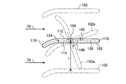
- FIG. 2 is a development view of a position where the inlet guide vanes are arranged.
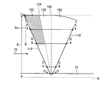
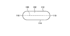
- FIG. 3 is a front view showing a schematic configuration of the inlet guide vane.
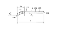
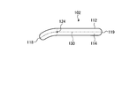
- 4 is a cross-sectional view taken along line AA in FIG. 5 is a cross-sectional view taken along line BB in FIG. 6 is a cross-sectional view taken along the line CC of FIG. 7 is a cross-sectional view taken along the line DD of FIG.
- FIG. 8 is a cross-sectional view of an inlet guide blade according to another embodiment.
- FIG. 9 is a cross-sectional view of another position of the inlet guide vane shown in FIG. FIG.
- FIG. 10 is a schematic diagram showing the relationship between the shape of the inlet guide vanes and the air resistance.
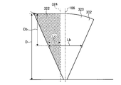
- FIG. 11 is a front view of an inlet guide blade according to another embodiment.
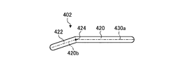
- FIG. 12 is a cross-sectional view of an inlet guide blade according to another embodiment.
- FIG. 13 is a front view of an inlet guide blade according to another embodiment.
- FIG. 14 is a cross-sectional view of an inlet guide blade according to another embodiment.
- FIG. 15 is a cross-sectional view of an inlet guide blade according to another embodiment.
- the compressor 1 can be used as a supply device of compressed air to a refrigerator, a petrochemical plant, or a natural gas plant, for example.
- the compressor 1 is configured as a two-stage compression centrifugal compressor which is an example of a turbo compressor in the present embodiment.
- a compression unit 3 and a drive unit 4 are accommodated in a casing 2.
- the compression unit 3 is disposed on the front side of the casing 2 and has a main shaft 31 that is rotatably supported with respect to the casing 2.
- the main shaft 31 is provided with an impeller 32.
- the impeller 32 is composed of a first stage impeller 32 a and a second stage impeller 32 b that are arranged in the extending direction of the main shaft 31 and in the extending direction of the axis R of the main shaft 31. .
- the compression unit 3 has a flow path formed by the casing 2 so as to be discharged after sucking and compressing the fluid.
- the flow path includes a first stage inlet flow path 33, a first stage diffuser 34, a return flow path 35, a second stage inlet flow path 36, a second stage diffuser 37, and a discharge flow path 38.
- the first stage inlet passage 33 is formed to reach the inflow side of the first stage impeller 32a.
- the first-stage inlet channel 33 is provided with a suction port 33 a for taking fluid into the casing 2.
- the first stage inlet flow path 33 is provided with inlet guide vanes 100.
- the first stage diffuser 34 is formed on the outflow side that is the outer periphery of the first stage impeller 32a.
- the inlet guide vane 100 will be described later.
- the return flow path 35 is formed between the first stage diffuser 34 and the second stage inlet flow path 36, and turns the fluid back from the first stage diffuser 34 to the second stage inlet flow path 36.
- the second stage inlet channel 36 is formed so as to reach the inflow side of the second stage impeller 32b.
- the second stage inlet channel 36 is provided with a guide vane (IGV) 36a.
- the second stage diffuser 37 is formed on the outflow side that is the outer periphery of the second stage impeller 32b.
- the discharge flow path 38 is formed in communication with the second stage diffuser 37.
- the discharge channel 38 is provided with a discharge port 38 a for discharging the fluid out of the casing 2.
- the drive unit 4 is disposed on the rear side of the casing 2 and includes an electric motor 41 and a power transmission unit 42.
- the power transmission unit 42 includes a first gear 42 a provided on the output shaft 41 a of the electric motor 41 and a second gear 42 b provided on the main shaft 31 of the compression unit 3 and meshing with the first gear 42 a.
- the main shaft 31 of the compression unit 3 rotates through the power transmission unit 42 by driving the electric motor 41 of the drive unit 4.
- the impeller 32 rotates with the main shaft 31.
- the fluid is sucked from the suction port 33a of the first stage inlet passage 33, compressed by the first stage impeller 32a via the inlet guide vane 100, and then converted into kinetic energy by the first stage diffuser 34.
- the fluid is folded back to the second-stage inlet channel 36 by the return channel 35, compressed again by the second-stage impeller 32b through the guide vane 36a, and then the kinetic energy is converted into internal energy by the second-stage diffuser 37. And discharged from the discharge port 38a of the discharge flow path 38.
- FIG. 2 is a development view of a position where the inlet guide vanes are arranged.
- FIG. 3 is a front view showing a schematic configuration of the inlet guide vane. 4 is a cross-sectional view taken along line AA in FIG. 5 is a cross-sectional view taken along line BB in FIG. 6 is a cross-sectional view taken along the line CC of FIG. 7 is a cross-sectional view taken along the line DD of FIG.
- the inlet guide vane 100 is arranged in the flow path on the upstream side of the first stage impeller 32a in the fluid flow direction.
- the inlet guide vane 100 includes a plate portion 102 and a rotating portion 104 that rotates the plate portion 102.
- a plurality of inlet guide vanes 100 are arranged around the axis R of the first stage inlet flow path 33.
- the inlet guide vane 100 has a blade-to-blade distance of l, which is the distance from the adjacent inlet guide vane 100 around the axis R. Further, the inlet guide blade 100 rotates the plate portion 102 by the rotating portion 104 in conjunction with other inlet guide blades 100.
- the plate portion 102 is disposed in the first stage inlet channel 33.
- the plate portion 102 is basically a flat plate shape, and the first surface 112 and the second surface 114 which are two surfaces having the largest area are parallel to each other.
- the plate portion 102 has a shape similar to a fan shape in which the length of the fluid flow direction 70 increases as it goes outward in the radial direction of the shaft center R, and the end portion on the radially outer side of the shaft center R forms an arc.
- an upstream end portion in the flow direction 70 is a front edge 118
- a downstream end portion in the flow direction 70 is a rear edge 119.
- the plate portion 102 has a front edge 118 and a rear edge 119 having an R shape. The shape of the plate portion 102 will be described in detail later.
- the rotation unit 104 rotates the plate unit 102 with the rotation axis 106 along the radial direction of the axis R as a base point.
- the inlet guide blade 100 moves the plate portion 102 to the positions of the plate portion 102a and the plate portion 102b by rotating the plate portion 102 about the rotation shaft 106 by the rotation portion 104 as shown in FIG. Can be made.
- the position of the plate portion 102 in which the center line 130 of the plate portion is oriented in parallel to the flow direction 70 is defined as an opening degree of 100%.
- the inlet guide blade 100 reduces the opening degree by rotating the plate portion 102 in the first rotation direction 140 and moving it in the direction of the plate portion 102a, for example.
- the second surface 114 becomes the upstream surface.
- the angle formed with the flow direction 70 is increased, and the plate portion 102a obstructs the flow of the fluid and increases the amount of the fluid flowing in.
- the inlet guide blade 100 increases the opening degree by rotating the plate portion 102 in the second rotation direction 142 and moving it in the direction of the plate portion 102b, for example.
- the plate portion 102b has a larger opening, so that the direction of the blades and the first-stage impeller 32a on the wake side are nearly parallel, and the flow of the fluid that has passed through the plate portion 102b is transferred to the first-stage impeller 32a.
- the direction in which the fluid can easily flow.
- wing 100 can be made to flow in more fluid than the position of the board part 102 by making it the position of the board part 102b.
- the inlet guide vane 100 adjusts the inflowing fluid by rotating the plate portion 102 by the rotating portion 104 and adjusting the opening degree.
- the inlet guide vane 100 rotates the plate portion 102 in the rotating portion 104 in the first rotation direction 140 in which the angle formed with the first stage impeller 32a is increased, and the opening degree is reduced to reduce the amount of air flowing in. Reduce the amount.
- the inlet guide vane 100 rotates the plate portion 102 in the second rotating direction 142 where the angle formed with the first stage impeller 32a is reduced by the rotating portion 104, and increases the opening degree, so that the inflowing air flows. Increase the amount.
- the plate portion 102 includes a flat plate portion 120 and a bent portion 122 disposed on the upstream side in the flow direction 70 from the flat plate portion 120.
- the flat plate portion 120 and the bent portion 122 are integrated.
- the plate portion 102 may be formed by processing one plate to provide the flat plate portion 120 and the bent portion 122, or may connect another plate to provide the flat plate portion 120 and the bent portion 122.
- the plate part 102 can be manufactured by performing a bending process by designating a bending position, a bending curvature, and a bending angle. Further, the plate portion 102 can also be manufactured by casting in which a die is formed from a bending position, a bending curvature, and a bending angle and then pressed. Further, the plate portion 102 can be manufactured by machining.
- the flat plate portion 120 is a plate in which the first surface 112 and the second surface 114 are parallel, and further, as shown in FIGS. 2 and 4, a center line (first surface 112) in a cross section orthogonal to the radial direction of the axis R. And a line connecting the midpoints of the second surface 114) 130 is a straight line.
- the bent portion 122 is disposed upstream of the flat plate portion 120 in the flow direction 70.
- the center line 130 is inclined with respect to the center line 130 of the flat plate portion 120.
- the first surface 112 and the second surface 114 in the cross section are parallel curves, and the center line 130 is also a curve.
- a boundary portion 124 between the bent portion 122 and the flat plate portion 120 is a position where the center line 130 is bent from a straight line.
- the bent portion 122 of the present embodiment has a shape that is inclined toward the second surface 114 with respect to the flat plate portion 120, that is, a shape in which the bent portion 122 is inclined toward the second rotation direction 142 side of the flat plate portion 120. .
- the bent portion 122 has a shape in which the angle formed with the flat plate portion 120 on the surface of the second surface 114 is smaller than 180 °, and the angle formed with the flat plate portion 120 on the surface of the first surface 112 is larger than 180 °. is there.
- the bent portion 122 is provided in the radial direction of the axis R in a range that is a distance Da from the radially outer end. That is, the bent portion 122 is provided at a part on the outer side in the radial direction of the shaft center R.
- the bent portion 122 is formed within a distance La from the front edge 118 in a cross section orthogonal to the rotation shaft 106.
- the ratio of the distance La to the total length (distance) L of the plate portion 102, that is, La / L has a constant value in a cross section orthogonal to the rotation axis 106.
- the boundary position 124 of the plate portion 102 is a straight line inclined at a predetermined angle with respect to the rotation shaft 106.
- the amount of warpage that is the deformation amount of the bent portion 122 is Y. .
- the plate portion 102 has a shape as described above. As shown in FIGS. 4 and 5, the radially outer portion of the shaft center R is provided with a bent portion 122 on the front edge 118 side. As shown in FIGS. 6 and 7, the radially inner portion of the axis R is only the flat plate portion 120.
- the plate portion 102 can be easily processed by not providing a bent portion at a radially inner portion of the axis R. Further, by providing the bent portion on the radially outer side of the shaft center R, the fluid can be guided efficiently.
- the inlet guide vane 100 can be made easily by making the member disposed in the flow path into a plate shape, and the manufacturing cost can be reduced.
- the inlet guide vane 100 has a shape in which the bent portion 122 of the plate portion 102 is inclined to the second surface 114 side with respect to the flat plate portion 120, that is, the bent portion 122 has the tip of the flat plate portion 120 on the second rotation direction 142 side.
- the angle formed by the surface of the second surface 114 is smaller than 180 °, and the angle formed by the surface of the first surface 112 is larger than 180 °.
- the plate portion 102 preferably has a relationship between the total length L and La such that 0.1 ⁇ La / L ⁇ 0.3.
- the plate portion 102 can efficiently suppress peeling of the negative pressure surface of the inlet guide vane (IGV) 100, that is, the negative pressure surface of the plate portion 102, by providing a bent portion that satisfies the above relationship.
- IGV inlet guide vane
- the plate portion 102 when the distance from the shaft center R to the end of the plate portion 102 in the radial direction R is D, the relationship between the distance D and the distance Da from the radially outer end is 0 ⁇ Da / D. It is preferable that ⁇ 0.9.
- the plate portion 102 has a blade-to-blade distance l between adjacent plate portions 102 and a deformation amount of the bent portion 122 (a direction perpendicular to the center line 130 between the center line 130 of the flat plate portion 120 and the front edge of the bent portion 122.
- the absolute value of Y / l is preferably 0.15 or less, and more preferably 0.10 or less, more preferably the absolute value of Y / l.
- the bent portion 122 is inclined toward the second surface 114 with respect to the flat plate portion 120, that is, the bent portion 122 is inclined toward the second rotational direction 142 side of the flat plate portion 120, the second Although the angle formed by the surface of the surface 114 is smaller than 180 ° and the angle formed by the surface of the first surface 112 is larger than 180 °, the shape is not limited to this.
- FIG. 8 is a cross-sectional view of an inlet guide blade according to another embodiment.
- FIG. 9 is a cross-sectional view of another position of the inlet guide vane shown in FIG.
- the plate portion 202 of the inlet guide vane shown in FIGS. 8 and 9 has a flat plate portion 220 and a bent portion 222.
- the plate portion 202 is connected to the flat plate portion 220 and the bent portion 222 at the boundary position 224.
- the bent portion 222 is disposed on the front edge 219 side.
- the plate portion 202 has a shape in which the bent portion 222 is inclined toward the first surface 212 with respect to the flat plate portion 220.
- the plate portion 202 has a shape in which the bent portion 222 is inclined with the tip of the flat plate portion 220 inclined toward the first rotation direction 140, and the angle formed by the surface of the first surface 212 is smaller than 180 °, and the surface of the second surface 214 It becomes a shape where the angle formed by is greater than 180 °.
- the plate portion 202 can suppress the separation of the fluid on the suction surface (second surface) and can efficiently guide the fluid.
- FIG. 10 is a schematic diagram showing the relationship between the shape of the inlet guide vane and the air resistance.
- the plate portions 102 and 202 examined the relationship between the amount of warpage (deformation amount) Y and the inter-blade distance l in each of the cases where the opening degree of the inlet guide vane (IGV) was 40%, 100%, and 130%. It is an example which shows a result.
- the warpage amount Y is deformed toward the second surfaces 114 and 214, that is, when the bent portion 122 as shown in FIGS.
- the deformation amount is positive and the first surface 112, 212 is deformed, that is, when the bent portion 222 as shown in FIGS.
- the direction of deformation is defined as negative.
- FIG. 10 when the amount of warping is positive, the efficiency can be increased by operating at an opening degree of 40%. Moreover, when the amount of warping is negative, the efficiency can be increased by operating the opening at 130%.
- the plate portion of the inlet guide vane has the direction of deforming the bent portion as the first surface side based on the assumed operating conditions, specifically, based on the opening during operation that places more importance on isolation. By deciding whether or not to perform the operation on the second surface side, it becomes possible to perform the operation efficiently.
- the plate portions 102 and 202 in the above embodiment are preferably straight lines in which the ratio of the bent portions 122 and 222 to the total length L in each cross section is constant and the boundary position 124 is inclined at a predetermined angle with respect to the rotation shaft 106. It is not limited to this.
- the plate portions 102 and 202 may have a curved shape at the boundary position 124 or a bent shape. Also in this case, when La / L at each position satisfies the above relationship, the fluid can be suitably guided, and the efficiency can be improved.
- the boundary position is not limited to the above.
- FIG. 11 is a front view of an inlet guide blade according to another embodiment.
- a plate portion 302 shown in FIG. 11 has a flat plate portion 320 and a bent portion 322.
- a boundary between the flat plate portion 320 and the bent portion 322 becomes a boundary position 324.
- the boundary position 324 of this embodiment is parallel to the rotation axis 106.
- the plate portion 302 has a fixed distance from the rotation shaft 106 and a bent portion 322 on the front edge side from the boundary position 324 on the front edge side, and the center line is inclined with respect to the flat plate portion 320.
- the plate 302 has a distance Lc from the front edge in the longitudinal direction of the cross section perpendicular to the axis R to the boundary position 324 at a distance Db from the radially outer end of the axis R.
- the total length Lb of the position is Lb. On the other hand, it becomes 0.1Lb or more and 0.3Lb or less.
- the distance Db is preferably 0.35 ⁇ Db / D ⁇ 0.7 with respect to the distance D.
- Db is zero at the radially outer end of the axis R.
- Db / D is 0 at the outer end in the radial direction of the axis R and 1.0 at the inner end.
- the plate 302 has a distance Db from the radially outer end of the shaft center R, with respect to the total length L in the longitudinal direction of the cross section orthogonal to the shaft center R.
- a bent portion is provided in the range of 0.1 to 0.3 L on the leading end side (front edge side) on the upstream side of the flow path.
- machining can be simplified by making the boundary position parallel to the rotation axis.
- the fluid can be suitably guided and the efficiency can be improved.
- FIG. 12 is a cross-sectional view of an inlet guide blade according to another embodiment.
- a plate portion 402 shown in FIG. 12 has a flat plate portion 420 and a bent portion 422.
- the flat plate portion 420 and the bent portion 422 are connected at the boundary position 424.
- the center line 420b in the cross section orthogonal to the rotation shaft 106 is a straight line, and is inclined with respect to the center axis 430a of the flat plate portion 420. That is, the plate portion 420 is a flat plate in which the bent portion 422 is inclined with respect to the flat plate portion 420.
- processing can be simplified.
- FIG. 13 is a front view of an inlet guide blade according to another embodiment.
- 14 is a cross-sectional view of an inlet guide vane of another embodiment, and is a cross-sectional view of the inlet guide vane shown in FIG. 13 taken along the line EE.
- the plate portion 102c shown in FIGS. 13 and 14 has the same shape as the plate portion 102 except that a slit is formed. Explanation of similar points is omitted.
- the slit 160 is formed in the bent portion 122. The slit 160 penetrates from the first surface 112 to the second surface 114. The slit 160 is formed in parallel to the front edge 118 of the plate portion 102c.
- the slit 160 is a long hole whose longitudinal direction is the direction in which the rotating shaft 106 extends.
- the opening of the first surface 112 (surface where the angle formed with the flat plate portion 120 on the surface is larger than 180 °) is smaller than the opening of the second surface 114 (surface formed with the flat plate portion 120 on the surface is smaller than 180 °). Is formed on the upstream side in the flow direction from the opening of the surface.
- FIG. 15 is a cross-sectional view of an inlet guide blade according to another embodiment.
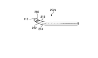
- a plate portion 202a shown in FIG. 15 has the same shape as the plate portion 202 except that a slit is formed. Explanation of similar points is omitted.
- the slit 260 is formed in the bent portion 222.
- the slit 260 penetrates from the first surface 212 to the second surface 214.
- the slit 260 is formed in parallel to the front edge 118 of the plate portion 202a.
- the opening of the second surface 214 (the surface where the angle formed with the flat plate portion on the surface is larger than 180 °) is the first surface 212 (the surface where the angle formed with the flat plate portion on the surface is smaller than 180 °). It is formed on the upstream side in the flow direction from the opening.
- the fluid passes through the slit when the plate portion opposite to the side where the flow can be efficiently rectified by the bent portion described above is arranged.
- loss can be reduced and the efficiency of a centrifugal compressor can be improved.
- the slit of the present embodiment is a straight hole in which the opening on the first surface and the opening on the second surface have the same shape, a diaphragm may be provided or an R shape may be provided in the opening portion.
Landscapes
- Engineering & Computer Science (AREA)
- Mechanical Engineering (AREA)
- General Engineering & Computer Science (AREA)
- Structures Of Non-Positive Displacement Pumps (AREA)
Abstract
簡単な形状で効率よく空気を流入させることができる入口案内羽根及び遠心圧縮機を提供する。入口案内羽根は、遠心圧縮機の流路の羽根車の上流に配置された入口案内羽根であって、前記流路に配置された板形状の板部と、前記遠心圧縮機の回転軸の径方向に沿った軸を回転軸とし、前記板部を回動させる回動部と、を有する。前記板部は、前記回動部の回転軸に直交する断面において、前記流路の上流側の先端に他の部分に対して、傾いている屈曲部を有する。
Description
本発明は、開度を調整可能な入口案内羽根及びこれを有する遠心圧縮機に関する。
ターボ冷凍機、石油化学プラントや天然ガスプラント等においては、遠心圧縮機が用いられている。遠心圧縮機では、インペラ(羽根車)の回転により流体に運動エネルギーを与えると共に、径方向外側に流体を吹き出すことで遠心力による圧力上昇を得ている。遠心圧縮機は、インペラの上流側に流入した空気を整流し、かつ、流入する空気の量を調整する入口案内羽根を備えているものがある(特許文献1参照)。入口案内羽根は、インペラに対する角度、つまり開度を可変とし、流路内の抵抗を変更可能とすることで、流入する空気の量を調整することができる。
入口案内羽根は、流体の流れに生じる乱れを少なくするため、翼形状とするものが多い。入口案内羽根は、翼形状に形成するため加工に手間とコストがかかる。
本発明は上述した課題を解決するものであり、簡単な形状で効率よく空気を流入させることができる入口案内羽根及び遠心圧縮機を提供することを目的とする。
上述の目的を達成するために、本発明は、入口案内羽根であって、遠心圧縮機の流路の羽根車の上流に配置された入口案内羽根であって、前記流路に配置された板形状の板部と、前記遠心圧縮機の回転軸の径方向に沿った軸を回転軸とし、前記板部を回動させる回動部と、を有し、前記板部は、前記回動部の回転軸に直交する断面において、前記流路の上流側の先端に他の部分に対して、傾いている屈曲部を有することを特徴とする。
また、前記屈曲部は、前記回動部の回転軸に直交する断面における中心線が曲線であることが好ましい。
また、前記屈曲部は、前記回動部の回転軸に直交する断面における中心線が直線であることが好ましい。
また、前記屈曲部は、前記回動部の回転軸に直交する断面の前記板部の長手方向の全長Lに対する他の部分との境界位置が一定であることが好ましい。
また、前記屈曲部は、前記全長Lに対して、前記流路の上流側の先端側の0.1L以上0.3L以下の範囲に形成されていることが好ましい。
また、前記屈曲部は、前記回動部の回転軸に直交する断面における前記回動部の回転軸と、他の部分との境界位置との距離が一定あることが好ましい。
また、前記屈曲部は、前記回転軸から前記板部の外径側端部の距離Dに対して径方向外側の端部から0.35D以上0.7D以下の位置において、前記回転軸に直交する断面の長手方向の全長Lに対して、前記流路の上流側の先端側の0.1以上0.3L以下の範囲に形成されていることが好ましい。
また、前記屈曲部は、前記回転軸から前記板部の外径側端部の距離Dに対して0.5Dの位置において、前記回転軸に直交する断面の長手方向の全長Lに対して、前記流路の上流側の先端側の0.1L以上0.3L以下の範囲に形成されていることが好ましい。
また、前記屈曲部は、絞り時に回動する側に傾斜していることが好ましい。
また、前記屈曲部は、過開度時に回動する側に傾斜していることが好ましい。
また、前記屈曲部は、表面において前記他の部分のなす角が180°より大きくなる面から、表面において前記他の部分のなす角が180°未満となる面に向けてスリットが形成され、前記スリットは、表面において前記他の部分のなす角が180°より大きくなる面側の開口が、表面において前記他の部分のなす角が180°より小さくなる面の開口よりも流れ方向の上流側に形成されていることが好ましい。
上述の目的を達成するために、本発明は、遠心圧縮機であって、上記のいずれかに記載の入口案内羽根と、前記入口案内羽根の下流側に配置された羽根車と、を有することを特徴とする。
本発明によれば、板形状の一部を加工した形状とすることで、形状を簡単にすることができ、かつ、設定した使用時に生じる損失を低減することができる。
以下に、本発明に係る実施の形態を図面に基づいて詳細に説明する。なお、この実施の形態によりこの発明が限定されるものではない。また、下記実施の形態における構成要素には、当業者が置換可能かつ容易なもの、あるいは実質的に同一のものが含まれる。圧縮機1は、例えば、冷凍機、石油化学プラントや天然ガスプラントへの圧縮空気の供給装置として用いることができる。
図1に示すように、圧縮機1は、本実施の形態では、ターボ形圧縮機の一例である2段圧縮の遠心圧縮機として構成されている。この圧縮機1は、ケーシング2に、圧縮部3と駆動部4とが収容されている。
圧縮部3は、ケーシング2の前側に配置されており、ケーシング2に対して回転可能に支持された主軸31を有している。主軸31には、羽根車(インペラ)32が設けられている。羽根車32は、主軸31の延在方向であって、主軸31における軸心Rの延在方向に並んで設けられた第一段羽根車32aと第二段羽根車32bとで構成されている。
また、圧縮部3は、流体を吸引して圧縮した後に吐出するようにケーシング2により形成された流路を有している。流路は、第一段入口流路33と、第一段ディフューザ34と、返流路35と、第二段入口流路36と、第二段ディフューザ37と、吐出流路38とで構成されている。第一段入口流路33は、第一段羽根車32aの流入側に至り形成されている。この第一段入口流路33には、流体をケーシング2内に取り込むための吸引口33aが設けられている。また、第一段入口流路33には、入口案内羽根100が設けられている。第一段ディフューザ34は、第一段羽根車32aの外周である流出側に形成されている。入口案内羽根100については、後述する。返流路35は、第一段ディフューザ34と第二段入口流路36との間に形成され、第一段ディフューザ34から第二段入口流路36に流体を折り返すものである。第二段入口流路36は、第二段羽根車32bの流入側に至り形成されている。この第二段入口流路36には、案内ベーン(IGV)36aが設けられている。第二段ディフューザ37は、第二段羽根車32bの外周である流出側に形成されている。吐出流路38は、第二段ディフューザ37に連通して形成されている。この吐出流路38には、流体をケーシング2外に吐出するための吐出口38aが設けられている。
駆動部4は、ケーシング2の後側に配置されており、電動機41および動力伝達部42を有している。動力伝達部42は、電動機41の出力軸41aに設けられた第一歯車42aと、圧縮部3の主軸31に設けられて第一歯車42aに噛合する第二歯車42bとで構成されている。
このような圧縮機1は、駆動部4の電動機41の駆動により、動力伝達部42を介して圧縮部3の主軸31が回転する。すると、主軸31と共に羽根車32が回転する。これにより、流体は、第一段入口流路33の吸引口33aから吸入され、入口案内羽根100を経て第一段羽根車32aで圧縮された後、第一段ディフューザ34で運動エネルギーを内部エネルギーに変換される。さらに、流体は、返流路35により第二段入口流路36に折り返され、案内ベーン36aを経て第二段羽根車32bで再び圧縮された後、第二段ディフューザ37で運動エネルギーを内部エネルギーに変換され、吐出流路38の吐出口38aから吐出される。
次に、図1に加え、図2から図7を用いて、入口案内羽根(IGV、案内ガイドベーン)100について説明する。図2は、入口案内羽根が配置された位置の展開図である。図3は、入口案内羽根の概略構成を示す正面図である。図4は、図3のA-A線断面図である。図5は、図3のB-B線断面図である。図6は、図3のC-C線断面図である。図7は、図3のD-D線断面図である。
入口案内羽根100は、上述したように、流体の流れ方向において、第一段羽根車32aの上流側の流路に配置されている。入口案内羽根100は、板部102と板部102を回動させる回動部104とを有する。入口案内羽根100は、図2に示すように、第一段入口流路33の軸心R周りに複数配置されている。入口案内羽根100は、軸心R周りに隣接する入口案内羽根100との距離である翼間距離がlとなる。また、入口案内羽根100は、他の入口案内羽根100と連動させて回動部104により板部102を回動させる。
板部102は、第一段入口流路33内に配置されている。板部102は、基本的に平板形状であり、面積が最も広い2つの面である第1面112と第2面114とが平行となる。板部102は、軸心Rの径方向外側に向かうにしたがって、流体の流れ方向70の長さが長くなり、軸心Rの径方向外側の端部が弧となる扇型に似た形状となる。板部102は、流れ方向70の上流側の端部が前縁118、流れ方向70の下流側の端部が後縁119となる。板部102は、前縁118、後縁119がR形状となっている。板部102の形状については後ほど詳細に説明する。
回動部104は、板部102を軸心Rの径方向に沿った回転軸106を基点として、板部102を回動させる。入口案内羽根100は、回動部104により回転軸106を軸として板部102を回動させることで、図2に示すように、板部102を、板部102aや板部102bの位置に移動させることができる。
ここで、本実施形態において、図2に示すように、板部の中心線130が流れ方向70に平行となる向きである板部102の位置を開度100%とする。入口案内羽根100は、板部102を第1回転方向140に回転させ、例えば、板部102aの方向に移動させることで、開度を小さくする。このとき、第2面114が上流側の面となる。開度が小さくなることで流れ方向70とのなす角が大きくなり、板部102aが流体の流れを妨げ、流入する流体の量を増加させる。入口案内羽根100は、板部102を第2回転方向142に回転させ、例えば、板部102bの方向に移動させることで、開度を大きくする。このとき、第1面112が上流側の面となる。板部102bは、開度が大きくなることで後流側の第一段羽根車32aと羽根の向きが平行に近くなり、板部102bを通過した流体の流れを、第一段羽根車32aに流体が流入しやすい方向とする。これにより、入口案内羽根100は、板部102bの位置とすることで、板部102の位置よりもより多くの流体を流入させることができる。
このように、入口案内羽根100は、回動部104で板部102を回動させ開度を調整することで、流入する流体を調整する。入口案内羽根100は、回動部104で板部102を、第1段羽根車32aとのなす角が大きくなる第1回転方向140に回転させ、開度を低くすることで、流入する空気の量を低減させる。入口案内羽根100は、回動部104で板部102を、第1段羽根車32aとのなす角が小さくなる第2回転方向142に回転させ、開度を高くすることで、流入する空気の量を増加させる。
次に、板部102の形状をより詳細に説明する。板部102は、平板部120と平板部120よりも流れ方向70の上流側に配置された屈曲部122とを有する。平板部120と屈曲部122は一体である。なお、板部102は、1枚の板を加工して平板部120と屈曲部122を設けても、別の板を連結して平板部120と屈曲部122を設けてもよい。板部102は、曲げる位置、曲げる曲率、曲げる角度を指定して、曲げ加工を行うことで製造することができる。また、板部102は、曲げる位置、曲げる曲率、曲げる角度から型を作ってプレスを行う鋳造でも製造することができる。また、板部102は、機械加工でも製造することができる。
平板部120は、第1面112と第2面114が平行な板であり、さらに、図2および図4に示すように軸心Rの径方向に直交する断面における中心線(第1面112と第2面114との中点を結んだ線)130が直線となる。
屈曲部122は、平板部120よりも流れ方向70の上流側に配置されている。屈曲部122は、中心線130が平板部120の中心線130に対して傾いている。本実施形態の屈曲部122は、断面における第1面112、第2面114が平行な曲線となり、中心線130も曲線となる。屈曲部122と平板部120の境界部分124は、中心線130が直線から折れ曲る位置である。本実施形態の、屈曲部122は、平板部120に対して、第2面114側に傾けた形状、つまり屈曲部122を平板部120の先端を第2回転方向142側に傾けた形状となる。つまり、屈曲部122は、第2面114の表面の平板部120とのなす角が180°より小さくなり、第1面112の表面の平板部120とのなす角が180°より大きくなる形状である。
屈曲部122は、軸心Rの径方向において、径方向外側の端部から距離Daとなる範囲に設けている。つまり、屈曲部122は、軸心Rの径方向の外側の一部に設けられている。
屈曲部122は、回転軸106に直交する断面において、前縁118から距離Laの範囲に形成されている。本実施形態の屈曲部122は、回転軸106に直交する断面において、板部102の全長(距離)Lに対する距離Laの割合、つまりLa/Lが一定の値となる。これにより、板部102の境界位置124は、回転軸106に対して所定角度傾斜した直線となる。板部102は、屈曲部122の変形量(平板部120の中心線130と、屈曲部122の前縁118と、の中心線130に直交する方向の長さ)である反り量がYとなる。
板部102は、以上のような形状である。図4及び図5に示すように軸心Rの径方向外側の部分は、前縁118側に屈曲部122が設けられる。図6及び図7に示すように、軸心Rの径方向内側の部分は、平板部120のみとなる。板部102は、軸心Rの径方向内側の部分に屈曲部を設けないことで、加工を簡単にすることができる。また、軸心Rの径方向外側に屈曲部を設けることで、効率よく流体を案内することができる。
入口案内羽根100は、流路に配置する部材を板形状とすることで、作成を簡単にすることができ、製造コストを低くすることができる。
また、入口案内羽根100は、板部102の屈曲部122を平板部120に対して、第2面114側に傾けた形状、つまり屈曲部122を平板部120の先端を第2回転方向142側に傾けた形状、第2面114の表面のなす角が180°より小さくなり、第1面112の表面のなす角が180°より大きくなる形状とすることで、板部102の開度を100%よりも小さくした場合に、負圧面(第1面)流体の剥離を抑制することができ、流体を効率よく案内することができる。
板部102は、全長LとLaとの関係が、0.1≦La/L≦0.3となることが好ましい。板部102は、上記関係を満たす屈曲部を設けることで、入口案内羽根(IGV)100の負圧面、つまり、板部102の負圧面の剥離を効率よく抑制することができる。
板部102は、軸心Rから板部102の軸心R径方向端部までの距離をDとした場合、距離Dと径方向外側の端部から距離Daとの関係が0≦Da/D≦0.9なることが好ましい。板部102は、上記関係を満たす屈曲部122を設けることで、加工に無理がなく、板部102の負圧面の剥離を効率よく抑制する入口案内羽根100とすることができる。
板部102は、隣接する板部102との翼間距離lと、屈曲部122の変形量(平板部120の中心線130と、屈曲部122の前縁との、中心線130に直交する方向の長さ)である反り量Yとの関係を、Y/lの絶対値を0.15以下とすることが好ましく、Y/lの絶対値を0.10以下とすることがより好ましい。板部102は、上記関係を満たす屈曲部122を設けることで、無駄に大きく曲げることなく板部102の負圧面の剥離を効率よく抑制する入口案内羽根100とすることができる。
上記実施形態では、屈曲部122を平板部120に対して、第2面114側に傾けた形状、つまり屈曲部122を平板部120の先端を第2回転方向142側に傾けた形状、第2面114の表面のなす角が180°より小さくなり、第1面112の表面のなす角が180°より大きくなる形状としたが、これに限定されない。
図8は、他の実施形態の入口案内羽根の断面図である。図9は、図8に示す入口案内羽根の他の位置の断面図である。図8及び図9に示す入口案内羽根の板部202は、平板部220と屈曲部222とを有する。板部202は、境界位置224で平板部220と屈曲部222とが接続されている。屈曲部222は、前縁219側に配置されている。板部202は、屈曲部222を平板部220に対して、第1面212側に傾けた形状である。つまり板部202は、屈曲部222が、平板部220の先端を第1回転方向140側に傾けた形状、第1面212の表面のなす角が180°より小さくなり、第2面214の表面のなす角が180°より大きくなる形状となる。
板部202は、開度を100%よりも大きくした場合に、負圧面(第2面)の流体の剥離を抑制することができ、流体を効率よく案内することができる。
図10は、入口案内羽根の形状と空気抵抗との関係を示す模式図である。板部102、202は、入口案内羽根(IGV)の開度を、40%、100%、130%のそれぞれの場合について、反り量(変形量)Yと翼間距離lとの関係について検討した結果を示す一例である。ここで、反り量Yは、第2面114、214側に変形している場合、つまり図2から図7のような屈曲部122が絞り時に回動する側に傾斜している形状の場合、変形量が正となり、第1面112、212側に変形している場合、つまり図8および図9のような屈曲部222が過開度時に回動する側に傾斜している形状の場合、変形量が負となる向きで定義した。図10に示すように、反り量が正の場合、開度を40%で運転することで、効率を高くすることができる。また、反り量が負の場合、開度を130%で運転することで、効率を高くすることができる。
以上より、入口案内羽根の板部は、想定される運転条件に基づいて、具体的にはより孤立を重視した運転時の開度に基づいて、屈曲部を変形させる向きを第1面側とするか第2面側とするかを決定することで、効率よく運転を行うことが可能となる。
上記実施形態の板部102、202は、各断面における全長Lに対する屈曲部122、222の割合を一定とし、境界位置124が回転軸106に対して所定角度傾斜した直線とすることが好ましいが、これに限定されない。板部102、202は、境界位置124が曲線となる形状でも折れ曲がった形状としてもよい。この場合も、各位置でのLa/Lが上記関係を満たすことで、流体を好適に案内することができ、効率を向上させることができる。なお、境界位置は、上記に限定されない。
図11は、他の実施形態の入口案内羽根の正面図である。図11に示す板部302は、平板部320と屈曲部322とを有する。平板部320と屈曲部322との境界が境界位置324となる。本実施形態の境界位置324は、回転軸106と平行となる。板部302は、回転軸106よりも一定距離、前縁側の境界位置324から前縁側が屈曲部322となり平板部320に対して中心線が傾斜している。
板部302は、軸心Rの径方向外側の端部から距離Dbの位置において、軸心Rに直交する断面の長手方向の前縁から境界位置324との距離Lcが、その位置の全長Lbに対して、0.1Lb以上0.3Lb以下となる。ここで、距離Dbは、距離Dに対して、0.35≦Db/D≦0.7であることが好ましい。Dbは、軸心Rの径方向外側の端部が0となる。Db/Dは、軸心R径方向の外側の端部が0となり、内側の端部が1.0となる。また、板部302は、距離Dbと距離Dの関係がDb/D=0.5の位置において、0.1Lb以上0.3Lb以下を満たす形状であることも好ましい。
板部302は、境界位置324が上記位置となることで、軸心Rの径方向外側の端部から距離Dbの位置において、軸心Rに直交する断面の長手方向の全長Lに対して、流路の上流側の先端側(前縁側)の0.1以上0.3L以下の範囲に屈曲部を設けられる。
このように、境界位置を回転軸に平行とすることで、加工を簡単にすることができる。また、軸心Rの径方向外側に屈曲部がより多く配置されるため、流体を好適に案内することができ、効率を向上させることができる。
また、上記実施形態では、屈曲部を中心線が曲線となる形状としたがこれに限定されない。図12は、他の実施形態の入口案内羽根の断面図である。図12に示す板部402は、平板部420と屈曲部422とを有する。板部402は、境界位置424で平板部420と屈曲部422とが接続されている。屈曲部422は、回転軸106に直交する断面における中心線420bが直線であり、平板部420の中心軸430aに対して傾斜している。つまり、板部420は、屈曲部422が平板部420に対して傾斜した平板である。このように、屈曲部422を平板としても上記と同様の効果を得ることができる。また、加工を簡単にすることができる。
図13は、他の実施形態の入口案内羽根の正面図である。図14は、他の実施形態の入口案内羽根の断面図であり、図13に示す入口案内羽根のE-E線断面図である。図13及び図14に示す板部102cは、スリットが形成されている以外、板部102と同様の形状である。同様の点については、説明を省略する。スリット160は、屈曲部122に形成されている。スリット160は、第1面112から第2面114に貫通している。また、スリット160は、板部102cの前縁118に平行に形成されている。スリット160は、回転軸106の延在方向が長手となる長穴である。スリット160は、第1面112(表面において平板部120とのなす角が180°より大きくなる面)の開口が、第2面114(表面において平板部120とのなす角が180°より小さくなる面)の開口よりも流れ方向の上流側に形成されている。
次に、図15は、他の実施形態の入口案内羽根の断面図である。図15に示す板部202aは、スリットが形成されている以外、板部202と同様の形状である。同様の点については、説明を省略する。スリット260は、屈曲部222に形成されている。スリット260は、第1面212から第2面214に貫通している。また、スリット260は、板部202aの前縁118に平行に形成されている。スリット260は、第2面214(表面において平板部とのなす角が180°より大きくなる面)の開口が、第1面212(表面において平板部とのなす角が180°より小さくなる面)の開口よりも流れ方向の上流側に形成されている。
このように、スリットを形成することで、上述した屈曲部により流れを効率よく整流できる側と反対側の板部が配置されている場合に流体がスリットを通過する。これにより、損失を低減することができ、遠心圧縮機の効率を向上させることができる。なお本実施形態のスリットは、第1面の開口と第2面の開口が同じ形状となる直穴としたが、絞りを設けてもよいし、開口部分にR形状を設けてもよい。
1 圧縮機
2 ケーシング
3 圧縮部
4 駆動部
31 主軸
32 羽根車
32a 第一段羽根車
32b 第二段羽根車
33 第一段入口流路
33a 吸引口
34 第一段ディフューザ
35 返流路
36 第二段入口流路
36a 案内ベーン
37 第二段ディフューザ
38 吐出流路
38a 吐出口
70 流れ方向
100 入口案内羽根
102 板部
104 回動部
106 回転軸
112 第1面
114 第2面
118 前縁
119 後縁
120 平板部
122 屈曲部
124 境界位置
130 中心線
140 第1回転方向
142 第2回転方向
D、Da、La 距離
L 全長
2 ケーシング
3 圧縮部
4 駆動部
31 主軸
32 羽根車
32a 第一段羽根車
32b 第二段羽根車
33 第一段入口流路
33a 吸引口
34 第一段ディフューザ
35 返流路
36 第二段入口流路
36a 案内ベーン
37 第二段ディフューザ
38 吐出流路
38a 吐出口
70 流れ方向
100 入口案内羽根
102 板部
104 回動部
106 回転軸
112 第1面
114 第2面
118 前縁
119 後縁
120 平板部
122 屈曲部
124 境界位置
130 中心線
140 第1回転方向
142 第2回転方向
D、Da、La 距離
L 全長
Claims (12)
- 遠心圧縮機の流路の羽根車の上流に配置された入口案内羽根であって、
前記流路に配置された板形状の板部と、
前記遠心圧縮機の回転軸の径方向に沿った軸を回転軸とし、前記板部を回動させる回動部と、を有し、
前記板部は、前記回動部の回転軸に直交する断面において、前記流路の上流側の先端に他の部分に対して、傾いている屈曲部を有することを特徴とする入口案内羽根。 - 前記屈曲部は、前記回動部の回転軸に直交する断面における中心線が曲線であることを特徴とする請求項1に記載の入口案内羽根。
- 前記屈曲部は、前記回動部の回転軸に直交する断面における中心線が直線であることを特徴とする請求項1に記載の入口案内羽根。
- 前記屈曲部は、前記回動部の回転軸に直交する断面の前記板部の長手方向の全長Lに対する他の部分との境界位置が一定であることを特徴とする請求項1から3のいずれか一項に記載の入口案内羽根。
- 前記屈曲部は、前記全長Lに対して、前記流路の上流側の先端側の0.1L以上0.3L以下の範囲に形成されていることを特徴とする請求項4に記載の入口案内羽根。
- 前記屈曲部は、前記回動部の回転軸に直交する断面における前記回動部の回転軸と、他の部分との境界位置との距離が一定あることを特徴とする請求項1から3のいずれか一項に記載の入口案内羽根。
- 前記屈曲部は、前記回転軸から前記板部の外径側端部の距離Dに対して径方向外側の端部から0.35D以上0.7D以下の位置において、前記回転軸に直交する断面の長手方向の全長Lに対して、前記流路の上流側の先端側の0.1L以上0.3L以下の範囲に形成されていることを特徴とする請求項6に記載の入口案内羽根。
- 前記屈曲部は、前記回転軸から前記板部の外径側端部の距離Dに対して0.5Dの位置において、前記回転軸に直交する断面の長手方向の全長Lに対して、前記流路の上流側の先端側の0.1L以上0.3L以下の範囲に形成されていることを特徴とする請求項6または7に記載の入口案内羽根。
- 前記屈曲部は、絞り時に回動する側に傾斜していることを特徴とする請求項1から8のいずれか一項に記載の入口案内羽根。
- 前記屈曲部は、過開度時に回動する側に傾斜していることを特徴とする請求項1から8のいずれか一項に記載の入口案内羽根。
- 前記屈曲部は、表面において前記他の部分のなす角が180°より大きくなる面から、表面において前記他の部分のなす角が180°未満となる面に向けてスリットが形成され、
前記スリットは、表面において前記他の部分のなす角が180°より大きくなる面側の開口が、表面において前記他の部分のなす角が180°より小さくなる面の開口よりも流れ方向の上流側に形成されていることを特徴とする請求項1から10のいずれか一項に記載の入口案内羽根。 - 請求項1から11のいずれか一項に記載の入口案内羽根と、
前記入口案内羽根の下流側に配置された羽根車と、を有することを特徴とする遠心圧縮機。
Priority Applications (2)
| Application Number | Priority Date | Filing Date | Title |
|---|---|---|---|
| CN201580078370.XA CN107429708A (zh) | 2015-04-14 | 2015-10-21 | 入口引导叶片及离心压缩机 |
| US15/565,732 US10544800B2 (en) | 2015-04-14 | 2015-10-21 | Inlet guide vane and centrifugal compressor |
Applications Claiming Priority (2)
| Application Number | Priority Date | Filing Date | Title |
|---|---|---|---|
| JP2015082553A JP6594019B2 (ja) | 2015-04-14 | 2015-04-14 | 入口案内羽根及び遠心圧縮機 |
| JP2015-082553 | 2015-04-14 |
Publications (1)
| Publication Number | Publication Date |
|---|---|
| WO2016166910A1 true WO2016166910A1 (ja) | 2016-10-20 |
Family
ID=57125802
Family Applications (1)
| Application Number | Title | Priority Date | Filing Date |
|---|---|---|---|
| PCT/JP2015/079650 Ceased WO2016166910A1 (ja) | 2015-04-14 | 2015-10-21 | 入口案内羽根及び遠心圧縮機 |
Country Status (4)
| Country | Link |
|---|---|
| US (1) | US10544800B2 (ja) |
| JP (1) | JP6594019B2 (ja) |
| CN (1) | CN107429708A (ja) |
| WO (1) | WO2016166910A1 (ja) |
Families Citing this family (3)
| Publication number | Priority date | Publication date | Assignee | Title |
|---|---|---|---|---|
| MY207242A (en) * | 2022-09-13 | 2025-02-08 | Tsurumi Mfg | Electric submersible pump |
| US12392354B2 (en) * | 2023-12-14 | 2025-08-19 | Valeo Systemes Thermiques | Blower device |
| JP2025128462A (ja) | 2024-02-22 | 2025-09-03 | 三菱重工コンプレッサ株式会社 | インレットガイドベーン及び回転機械 |
Citations (4)
| Publication number | Priority date | Publication date | Assignee | Title |
|---|---|---|---|---|
| US3583827A (en) * | 1969-11-10 | 1971-06-08 | Westinghouse Electric Corp | Spin vane control for fans |
| JPS6028300U (ja) * | 1983-08-02 | 1985-02-26 | 三菱重工業株式会社 | 回転流体機械 |
| US20120263586A1 (en) * | 2009-11-03 | 2012-10-18 | Ingersoll-Rand Company | Inlet guide vane for a compressor |
| JP2013245575A (ja) * | 2012-05-24 | 2013-12-09 | Ihi Corp | インレットガイドベーン及びターボ機械 |
Family Cites Families (18)
| Publication number | Priority date | Publication date | Assignee | Title |
|---|---|---|---|---|
| EP0229519B2 (en) * | 1985-12-24 | 1996-11-13 | Holset Engineering Company Limited | Improvements in and relating to compressors |
| JPH05164091A (ja) * | 1991-12-10 | 1993-06-29 | Mitsubishi Heavy Ind Ltd | 軸流ファン |
| DE19546863A1 (de) * | 1994-12-21 | 1996-06-27 | Komet Stahlhalter Werkzeug | Verfahren und Vorrichtung zur Endbearbeitung gehärteter Werkstücke |
| CA2184882A1 (en) * | 1995-09-08 | 1997-03-09 | Hideomi Harada | Turbomachinery with variable-angle flow guiding vanes |
| JPH1122695A (ja) | 1997-06-30 | 1999-01-26 | Ishikawajima Harima Heavy Ind Co Ltd | 遠心圧縮機のインペラ翼構造 |
| US6039534A (en) * | 1998-09-21 | 2000-03-21 | Northern Research And Engineering Corp | Inlet guide vane assembly |
| US6276896B1 (en) * | 2000-07-25 | 2001-08-21 | Joseph C. Burge | Apparatus and method for cooling Axi-Centrifugal impeller |
| JP3653005B2 (ja) | 2001-04-27 | 2005-05-25 | 三菱重工業株式会社 | 遠心圧縮機および冷凍機 |
| DE602004001908T2 (de) * | 2003-04-30 | 2007-04-26 | Holset Engineering Co. Ltd., Huddersfield | Kompressor |
| EP1714008B1 (en) * | 2003-12-31 | 2009-02-25 | Honeywell International | Turbocharger assembly |
| EP2020509B1 (en) * | 2007-08-03 | 2014-10-15 | Hitachi, Ltd. | Centrifugal compressor, impeller and operating method of the same |
| JP2009041431A (ja) | 2007-08-08 | 2009-02-26 | Ihi Corp | 遠心圧縮機のディフューザ |
| US8935926B2 (en) * | 2010-10-28 | 2015-01-20 | United Technologies Corporation | Centrifugal compressor with bleed flow splitter for a gas turbine engine |
| CN202690536U (zh) * | 2012-07-20 | 2013-01-23 | 沈阳鼓风机集团齿轮压缩机有限公司 | 一种聚烯烃循环气压缩机入口导叶调节器 |
| JP5599528B2 (ja) * | 2012-08-30 | 2014-10-01 | 三菱重工業株式会社 | 遠心圧縮機 |
| US10125793B2 (en) * | 2013-02-22 | 2018-11-13 | Mitsubishi Heavy Industries, Ltd. | Centrifugal compressor |
| CN104968944B (zh) * | 2013-02-22 | 2019-08-23 | 三菱重工业株式会社 | 离心压缩机 |
| EP3012461A4 (en) * | 2013-06-20 | 2017-02-08 | Mitsubishi Heavy Industries, Ltd. | Centrifugal compressor |
-
2015
- 2015-04-14 JP JP2015082553A patent/JP6594019B2/ja active Active
- 2015-10-21 CN CN201580078370.XA patent/CN107429708A/zh active Pending
- 2015-10-21 US US15/565,732 patent/US10544800B2/en active Active
- 2015-10-21 WO PCT/JP2015/079650 patent/WO2016166910A1/ja not_active Ceased
Patent Citations (4)
| Publication number | Priority date | Publication date | Assignee | Title |
|---|---|---|---|---|
| US3583827A (en) * | 1969-11-10 | 1971-06-08 | Westinghouse Electric Corp | Spin vane control for fans |
| JPS6028300U (ja) * | 1983-08-02 | 1985-02-26 | 三菱重工業株式会社 | 回転流体機械 |
| US20120263586A1 (en) * | 2009-11-03 | 2012-10-18 | Ingersoll-Rand Company | Inlet guide vane for a compressor |
| JP2013245575A (ja) * | 2012-05-24 | 2013-12-09 | Ihi Corp | インレットガイドベーン及びターボ機械 |
Also Published As
| Publication number | Publication date |
|---|---|
| US10544800B2 (en) | 2020-01-28 |
| US20180080470A1 (en) | 2018-03-22 |
| JP6594019B2 (ja) | 2019-10-23 |
| CN107429708A (zh) | 2017-12-01 |
| JP2016200119A (ja) | 2016-12-01 |
Similar Documents
| Publication | Publication Date | Title |
|---|---|---|
| JP5608062B2 (ja) | 遠心型ターボ機械 | |
| JP4888436B2 (ja) | 遠心圧縮機とその羽根車およびその運転方法 | |
| WO2011007467A1 (ja) | インペラおよび回転機械 | |
| JP7019446B2 (ja) | 遠心圧縮機 | |
| CN105917123B (zh) | 带有具有s形后缘的叶片的离心式压缩机叶轮 | |
| WO2016042818A1 (ja) | 遠心羽根車及び遠心圧縮機 | |
| JP6594019B2 (ja) | 入口案内羽根及び遠心圧縮機 | |
| US10975883B2 (en) | Centrifugal rotary machine | |
| JP6763804B2 (ja) | 遠心圧縮機 | |
| CN119755134B (zh) | 一种低振动叶片结构及应用其的离心或透平流体机械 | |
| CN106662119B (zh) | 用于涡轮机的改进的涡管、包括所述涡管的涡轮机和操作的方法 | |
| US10844863B2 (en) | Centrifugal rotary machine | |
| US11047393B1 (en) | Multi-stage centrifugal compressor, casing, and return vane | |
| WO2017119229A1 (ja) | 圧縮機 | |
| WO2016132575A1 (ja) | 遠心圧縮機 | |
| WO2016075955A1 (ja) | 羽根車及び遠心圧縮機 | |
| JP2019007383A (ja) | 遠心式流体機械 | |
| JP2002021784A (ja) | 遠心圧縮機 | |
| WO2017170285A1 (ja) | 遠心羽根車、およびこれを備える遠心式流体機械 | |
| KR20150057482A (ko) | 원심 압축기 |
Legal Events
| Date | Code | Title | Description |
|---|---|---|---|
| 121 | Ep: the epo has been informed by wipo that ep was designated in this application |
Ref document number: 15889244 Country of ref document: EP Kind code of ref document: A1 |
|
| WWE | Wipo information: entry into national phase |
Ref document number: 15565732 Country of ref document: US |
|
| NENP | Non-entry into the national phase |
Ref country code: DE |
|
| 122 | Ep: pct application non-entry in european phase |
Ref document number: 15889244 Country of ref document: EP Kind code of ref document: A1 |