EP0229519B2 - Improvements in and relating to compressors - Google Patents
Improvements in and relating to compressors Download PDFInfo
- Publication number
- EP0229519B2 EP0229519B2 EP86310005A EP86310005A EP0229519B2 EP 0229519 B2 EP0229519 B2 EP 0229519B2 EP 86310005 A EP86310005 A EP 86310005A EP 86310005 A EP86310005 A EP 86310005A EP 0229519 B2 EP0229519 B2 EP 0229519B2
- Authority
- EP
- European Patent Office
- Prior art keywords
- compressor
- wall
- holes
- blades
- vanes
- Prior art date
- Legal status (The legal status is an assumption and is not a legal conclusion. Google has not performed a legal analysis and makes no representation as to the accuracy of the status listed.)
- Expired - Lifetime
Links
Images


Classifications
-
- F—MECHANICAL ENGINEERING; LIGHTING; HEATING; WEAPONS; BLASTING
- F04—POSITIVE - DISPLACEMENT MACHINES FOR LIQUIDS; PUMPS FOR LIQUIDS OR ELASTIC FLUIDS
- F04D—NON-POSITIVE-DISPLACEMENT PUMPS
- F04D29/00—Details, component parts, or accessories
- F04D29/40—Casings; Connections of working fluid
- F04D29/42—Casings; Connections of working fluid for radial or helico-centrifugal pumps
- F04D29/4206—Casings; Connections of working fluid for radial or helico-centrifugal pumps especially adapted for elastic fluid pumps
- F04D29/4213—Casings; Connections of working fluid for radial or helico-centrifugal pumps especially adapted for elastic fluid pumps suction ports
-
- F—MECHANICAL ENGINEERING; LIGHTING; HEATING; WEAPONS; BLASTING
- F04—POSITIVE - DISPLACEMENT MACHINES FOR LIQUIDS; PUMPS FOR LIQUIDS OR ELASTIC FLUIDS
- F04D—NON-POSITIVE-DISPLACEMENT PUMPS
- F04D27/00—Control, e.g. regulation, of pumps, pumping installations or pumping systems specially adapted for elastic fluids
- F04D27/02—Surge control
- F04D27/0207—Surge control by bleeding, bypassing or recycling fluids
- F04D27/0215—Arrangements therefor, e.g. bleed or by-pass valves
-
- F—MECHANICAL ENGINEERING; LIGHTING; HEATING; WEAPONS; BLASTING
- F04—POSITIVE - DISPLACEMENT MACHINES FOR LIQUIDS; PUMPS FOR LIQUIDS OR ELASTIC FLUIDS
- F04D—NON-POSITIVE-DISPLACEMENT PUMPS
- F04D29/00—Details, component parts, or accessories
- F04D29/40—Casings; Connections of working fluid
- F04D29/52—Casings; Connections of working fluid for axial pumps
- F04D29/522—Casings; Connections of working fluid for axial pumps especially adapted for elastic fluid pumps
- F04D29/526—Details of the casing section radially opposing blade tips
-
- F—MECHANICAL ENGINEERING; LIGHTING; HEATING; WEAPONS; BLASTING
- F04—POSITIVE - DISPLACEMENT MACHINES FOR LIQUIDS; PUMPS FOR LIQUIDS OR ELASTIC FLUIDS
- F04D—NON-POSITIVE-DISPLACEMENT PUMPS
- F04D29/00—Details, component parts, or accessories
- F04D29/66—Combating cavitation, whirls, noise, vibration or the like; Balancing
- F04D29/68—Combating cavitation, whirls, noise, vibration or the like; Balancing by influencing boundary layers
- F04D29/681—Combating cavitation, whirls, noise, vibration or the like; Balancing by influencing boundary layers especially adapted for elastic fluid pumps
- F04D29/685—Inducing localised fluid recirculation in the stator-rotor interface
-
- Y—GENERAL TAGGING OF NEW TECHNOLOGICAL DEVELOPMENTS; GENERAL TAGGING OF CROSS-SECTIONAL TECHNOLOGIES SPANNING OVER SEVERAL SECTIONS OF THE IPC; TECHNICAL SUBJECTS COVERED BY FORMER USPC CROSS-REFERENCE ART COLLECTIONS [XRACs] AND DIGESTS
- Y10—TECHNICAL SUBJECTS COVERED BY FORMER USPC
- Y10S—TECHNICAL SUBJECTS COVERED BY FORMER USPC CROSS-REFERENCE ART COLLECTIONS [XRACs] AND DIGESTS
- Y10S415/00—Rotary kinetic fluid motors or pumps
- Y10S415/914—Device to control boundary layer
Definitions
- the present invention relates to compressors e.g. axial and centrifugal compressors and multi-stage versions thereof.
- Compressors normally comprise an impeller wheel, carrying a plurality of blades or vanes, and mounted on an axis for rotation within a stationary housing. Rotation of this impeller wheel causes gas (usually air) to be drawn into the impeller wheel and to be discharged to a passage or passages for transferring the compressed gas to its destination.
- gas usually air
- the gas is discharged centrifugally and in the case of an axial compressor the gas is discharged axially.
- a turbine drivon compressor in e.g. a turbocharger
- the compressor impeller wheel and the turbine wheel are mounted on a common axis so that rotation of the turbine wheel causes rotation of the impeller wheel.
- US-A 4 248 566 describes a compressor arrangement comprising an Impeller wheel induding a plurality of blades or vanes each of which includes a leading edge, a trailing edge and an outer free edge, said wheel being mounted for rotation within a stationary housing, which housing includes an inner wall and an outer wall, at least part of the inner surface of the inner wall being in dose proximity to, and of similar contour to, the outer free edges of the blades or vanes, said outer wall forming a gas intake extending in an axial direction.
- the arrangement indudes an annular control slot formed in the housing which allows an inflow of gas from outside the housing to the impeller wheel when it is running at high r.p.m.
- German Patent 1087747 shows a typical approach for blowing off excess air delivered by a compressor when a significant reduction in delivery output is required, for example in the process industry.
- a valve 12 opens to let excess airflow from the compressor discharge through a bypass pipe 11 in cases where the output from the compressor diffuser 6 is not as great as in the unbypassed condition.
- a compressor comprising an impeller wheel including a plurality of vanes or blades each of which includes a leading edge, a trailing edge and an outer free edge, said wheel being mounted for rotation within a stationary housing, which housing includes an inner wall and an outer wall, at least part of the inner surface of the inner wall being in close proximity to, and of similar contour to, the outer free edges of the blade or vanes, said outer wall forming a gas intake extending in an axial direction, said gas intake surrounding said inner wall, said inner wall forming an inlet to said impeller wheel in a region adjacent the leading edges of said blades or vanes, a chamber formed between said inner and outer walls in a region at least partly surrounding said blades or vanes, a communication being provided through said inner wall between said chamber and the inner surface of said inner wall, said communication providing a bidirectional flowpath through said inner wall, between said chamber and the inner surface of said inner wall which flowpath is open at all times and gas movement in one direction or in the other direction through said flowpath is in
- the communication between the chamber and the inner surface of the inner wall may be an annular slot extending around the inner wall and bridged by a series of connecting webs or may be a plurality of holes.
- the communication comprises a plurality of holes then it is preferred that the number of such holes is not equal to, nor a multiple of, nor a factor of, the number of blades or vanes on the impeller wheel. Excitation may well occur in the event that the number of such holes is equal to, a multiple of, or a factor of, the number of blades or vanes.
- the preferred number of holes (subject to the above condition) is from 29 to 43.
- the total area of the holes or the slot at the inner surface of the inner wall is from 13 to 23% of the inducer annular area (I.e. the frontal area of the impeller wheel at the leading edge minus the hub area).
- the holes or slot are preferably located at a point along the meridional length just upstream of the point of minimum static pressure, and more preferably at a point some 65 to 75% of the distance from the leading edge of the blades to the minimum static pressure point
- the point of location of the slot or holes is thus typically some 22 to 34% along the meridional length from the leading edges of the blades or vanes.
- the holes or slots are preferably located some 15 to 25% along the length of the outer free edges of the blades from the leading edges.
- the pressure at the impeller end of the slot or holes is less than the pressure at the chamber end of the slot or holes and air thus flows through the slot or holes from the annular chamber to the impeller wheel thereby increasing the amount of air reaching the impeller wheel.
- the pressure at the impeller end of the slot or holes increases to above that at the chamber end of the slots or holes and thus air bleeds out of the area swept by the impeller wheel, through the slot or holes and through the annular chamber, thereby reducing the amount of air in the impeller wheel.
- the air bleeding out of the impeller wheel is thus recirculated to the inlet. This stabilizes compressor operation, moving the surge line to lower flow over the entire r.p.m. range of the compressor.
- the compressor of the present invention is especially useful when forming part of a turbocharger for an internal combustion engine particularly where an air deaner is provided upstream of the air intake to the compressor.
- This latter preference is because the air deaner results in the air pressure in the intake being depressed below atmospheric to a greater extent than without an air deaner and thus results in even better operation of the compressor of the invention due to the pressure differential between the two ends of the slot of holes at low flow (i.e. near surge) being greater.
- a number of compressors e.g. axial, centrifugal or both are connected in series so that the outlet from one compressor leads to the inlet of the next compressor in the series.
- One or more of the compressors in series may be in accordance with the invention.
- FIG. 1 there is shown a graph plotting pressure against mass flow in a single stage centrifugal compressor.
- the area between the lines D and E which is shown by shading, indicates a typical engine r.p.m. range over which a compressor not incorporating the present invention will operate. There is however a requirement to increase the engine r.p.m. range to cover an area between the lines D and B on the graph and it is therefore necessary to a;ter the characteristics of the compressor in order to move the surge line from the line marked S 1 to the line marked S 2 . This can be achieved by use of the present invention. Similar results can be achieved with an axial compressor.
- FIG. 2 there is shown a cross-section view of a single stage centrifugal compressor comprising a housing 10 having an impeller wheel 12 mounted in conventional manner for rotation therein.
- the wheel indudes a plurality of blades or vanes 14 of conventional design and each induding a leading edge 16, a trailing edge 18 and an outer free edge 20.
- the housing includes an outer wall 22, defining an intake 24 for gas such as air, and a passageway or passageways 26 for carrying compressed gas from the impeller wheel 12 to its destination e.g. the inlet manifold of an internal combustion engine.
- An inner wall 28 defines an inlet 30 to the impeller and an inner surface 32 of said inner wall 28 is in dose proximity to and of extremely similar contour to, the outer free edges 20 of the blades or vanes 14.
- the inner wall 28 extends a short distance upstream from the blades 14 of the impeller wheel 12 whereby to form an annular space or chamber 34 between the walls 22 and 28.
- the annular chamber 34 partly surrounds the impeller wheel 12.
- An annular slot 36 is formed in the wall 28 and a series of webs 38 serve to bridge the annular slot at intervals round its circumference.
- the slot 36 is located along the meridional length (line A on the drawing) at a point just upstream of the point of minimum static pressure. This point is preferably some 65 to 75% of the distance from the leading edges 16 of the blades or vanes 14 to the point of minimum static pressure and is typically 22 to 34% of the impeller blade length. In the arrangement shown in Figure 1 the slot is located some 73% of the distance from the leading edge 16 of the blades 14 to the point of minimum static pressure and is 30% of the length of the impeller blades 14 from the leading edges 16 of the blades.
- the total area of the slot is normally of the order of 13 to 23% of the inducer annular area In the arrangement shown the total area of the slot is 15% of the inducer annular area.
- the impeller wheel 12 In operation the impeller wheel 12 is rotated e.g. by a turbine wheel (not shown) attached to a common axis with the compressor wheel and this causes air to be drawn into the impeller wheel 12 through intake 24 and inlet 30. The air is compressed by the impeller wheel 12 and Is then fed to its ultimate destination via passageway or passageways 26.
- the pressure in the chamber 34 is normally lower than atmospheric pressure and during high flow and high r.p.m. operation the pressure in the area swept by the impeller wheel is less than in the chamber 34 and thus air flows through the slot 36 from the chamber 34 to the impeller wheel 12 thereby increasing the amount of air reaching the impeller wheel, and increasing its maximum flow capacity. As the flow through the impeller wheel 12 drops or as r.p.m.
- FIG. 3 there is shown an alternative embodiment in which the slot 36 is replaced by a series of holes 40.
- the positioning of the holes 40 along the meridional length and area of the holes at the inner surface 32 is similar to the positioning and area of the slot 36 in Figure 2.
- the number of holes should be arranged so that it is not equal to, nor a multiple of, nor a factor of the number of blades on the compressor wheel. If the number of holes is a multiple of or a factor of the number of blades then excitation can be induced. In the arrangement shown in Figure 3 the number of holes 40 is 29 and the number of blades is 16.
- FIG. 4 there is shown a further alternative embodiment of the invention in which the chamber 34 is formed by a series of blind bores 42 in the wall of the housing.
- the inner and outer walls 28 and 22 respectively are thus connected between these bores 42.
- the bores may be connected either to an annular slot similar to slot 36 in Figure 2 or to a series of holes similar to those holes 40 in Figure 3.
- FIG. 5 there is shown an arrangement In which the chamber 34 is formed partly in the housing 10 and partly by an annular slot 44 (with connecting webs) or series of holes 44 formed in a ring 46 which may be aluminium or plastic.
- the chamber 34 as in other embodiments, communications with the impeller wheel 12 via a series of holes or a slot.
- Axial compressor 100 indudes an impeller wheel 12 having a series of vanes or blades 106 each of which includes a leading edge 108, a trailing edge 110 and an outer free edge 112. Air compressed by compressor 100 is fed via axial outlet 114 to the inlet 116 of centrifugal compressor 102.
- Axial compressor 100 includes inner and outer walls 28 and 22 respectively defining an annular space or chamber 34 as in the arrangement of Figures 2 and 3.
- a series of holes 40 (which could alternatively be a slot 36) is provided as in the device of Figure 3.
Description
- The present invention relates to compressors e.g. axial and centrifugal compressors and multi-stage versions thereof.
- Compressors normally comprise an impeller wheel, carrying a plurality of blades or vanes, and mounted on an axis for rotation within a stationary housing. Rotation of this impeller wheel causes gas (usually air) to be drawn into the impeller wheel and to be discharged to a passage or passages for transferring the compressed gas to its destination. In the case of a centrifugal compressor the gas is discharged centrifugally and in the case of an axial compressor the gas is discharged axially. In the case of a turbine drivon compressor in e.g. a turbocharger, the compressor impeller wheel and the turbine wheel are mounted on a common axis so that rotation of the turbine wheel causes rotation of the impeller wheel.
- It has been proposed in U.S. Specification No. 4,248,566 to form an annular control slot in the stationary housing so as to allow an inflow of gas from outside the housing to the impeller wheel under high r.p.m. conditions nf compressor operation and to allow gas flow to bleed from the impeller wheel to the exterior of the housing when the wheel is operating at lower r:p.m. whereby to flow stabilize the impeller wheel at part r.p.m. operation.
- Such an arrangement however provides stable operation over only a relatively narrow range of engine r.p.m. and there is now a requirement to increase the engine r.p.m. range over which compressors can operate in stable manner. This is achieved in accordance with the present invention by providing communication between the chamber in which the compressor wheel rotates and an annular chamber formed in the gas intake to the impeller wheel and preferably at least partly surrounding the impeller wheel. The air is thus not bled to the exterior of the housing, and thus atmosphere, nor drawn in from atmosphere separately from the normal gas intake to the compressor (as in US-A 4 248 566), but is bled back to the normal intake or Is drawn from the normal intake.
- US-A 4 248 566 describes a compressor arrangement comprising an Impeller wheel induding a plurality of blades or vanes each of which includes a leading edge, a trailing edge and an outer free edge, said wheel being mounted for rotation within a stationary housing, which housing includes an inner wall and an outer wall, at least part of the inner surface of the inner wall being in dose proximity to, and of similar contour to, the outer free edges of the blades or vanes, said outer wall forming a gas intake extending in an axial direction. The arrangement indudes an annular control slot formed in the housing which allows an inflow of gas from outside the housing to the impeller wheel when it is running at high r.p.m. and allows gas to bleed from the impeller wheel to the oxterior of the housing when it is running at low r.p.m. This arrangement however provides stable operation over only a relatively narrow range of engine r.p.m. In the arrangement of the present invention the air is not bled to the exterior of the housing (i.e. the atmosphere) nor drawn in from the atmosphere separately from the normal gas intake to the compressor, but is drawn from and bled back to the normal intake to the compressor. This arrangement provides stable operation over a wider r.p.m. range.
- German Patent 1087747 shows a typical approach for blowing off excess air delivered by a compressor when a significant reduction in delivery output is required, for example in the process industry. In the German patent a
valve 12 opens to let excess airflow from the compressor discharge through a bypass pipe 11 in cases where the output from the compressor diffuser 6 is not as great as in the unbypassed condition. - According to the present invention there is disclosed a compressor comprising an impeller wheel including a plurality of vanes or blades each of which includes a leading edge, a trailing edge and an outer free edge, said wheel being mounted for rotation within a stationary housing, which housing includes an inner wall and an outer wall, at least part of the inner surface of the inner wall being in close proximity to, and of similar contour to, the outer free edges of the blade or vanes, said outer wall forming a gas intake extending in an axial direction, said gas intake surrounding said inner wall, said inner wall forming an inlet to said impeller wheel in a region adjacent the leading edges of said blades or vanes, a chamber formed between said inner and outer walls in a region at least partly surrounding said blades or vanes, a communication being provided through said inner wall between said chamber and the inner surface of said inner wall, said communication providing a bidirectional flowpath through said inner wall, between said chamber and the inner surface of said inner wall which flowpath is open at all times and gas movement in one direction or in the other direction through said flowpath is in response to the pressure differential between said chamber and the area swept by the vanes or blades, one end of said flowpath opening into the inner surface of the inner wall at a position not more than 34% along the meridional length from the leading edge of the blades or vanes, and the total cross-sectional area of said opening of the flowpath to the inner surface of the inner wall being at least 13% of the inducer annular area (i.e. the frontal area of the impeller wheel at the leading edge minus of the hub area), and communication being provided between said gas intake and said chamber, which communication is open at all times.
- The communication between the chamber and the inner surface of the inner wall may be an annular slot extending around the inner wall and bridged by a series of connecting webs or may be a plurality of holes.
- In the event that the communication comprises a plurality of holes then it is preferred that the number of such holes is not equal to, nor a multiple of, nor a factor of, the number of blades or vanes on the impeller wheel. Excitation may well occur in the event that the number of such holes is equal to, a multiple of, or a factor of, the number of blades or vanes. The preferred number of holes (subject to the above condition) is from 29 to 43.
- Preferably the total area of the holes or the slot at the inner surface of the inner wall is from 13 to 23% of the inducer annular area (I.e. the frontal area of the impeller wheel at the leading edge minus the hub area).
- In the case of centrifugal compressors the holes or slot are preferably located at a point along the meridional length just upstream of the point of minimum static pressure, and more preferably at a point some 65 to 75% of the distance from the leading edge of the blades to the minimum static pressure point The point of location of the slot or holes is thus typically some 22 to 34% along the meridional length from the leading edges of the blades or vanes.
- In the case of axial compressors the holes or slots are preferably located some 15 to 25% along the length of the outer free edges of the blades from the leading edges.
- The final exact selection of the various preferred features (e.g. slot or holes, area, and position of hole or slot) for optimum benefit depends upon the particular compressor and its use.
- During high flow and high r.p.m. operation of the compressor the pressure at the impeller end of the slot or holes is less than the pressure at the chamber end of the slot or holes and air thus flows through the slot or holes from the annular chamber to the impeller wheel thereby increasing the amount of air reaching the impeller wheel. During operation of the compressor near its surge line however, the pressure at the impeller end of the slot or holes increases to above that at the chamber end of the slots or holes and thus air bleeds out of the area swept by the impeller wheel, through the slot or holes and through the annular chamber, thereby reducing the amount of air in the impeller wheel. The air bleeding out of the impeller wheel is thus recirculated to the inlet. This stabilizes compressor operation, moving the surge line to lower flow over the entire r.p.m. range of the compressor.
- Use of the compressor of the present invention enables compressor operation over a wider range of engine r.p.m. than was previously possible.
- The compressor of the present invention is especially useful when forming part of a turbocharger for an internal combustion engine particularly where an air deaner is provided upstream of the air intake to the compressor. This latter preference is because the air deaner results in the air pressure in the intake being depressed below atmospheric to a greater extent than without an air deaner and thus results in even better operation of the compressor of the invention due to the pressure differential between the two ends of the slot of holes at low flow (i.e. near surge) being greater.
- In a multi-stage compressor a number of compressors e.g. axial, centrifugal or both are connected in series so that the outlet from one compressor leads to the inlet of the next compressor in the series. One or more of the compressors in series may be in accordance with the invention.
- The invention will now be further described by way of example with reference to the accompanying drawings in which :-
- Figure 1 is a graph of pressure against mass flow in a compressor ;
- Figure 2 is a cross-section through part of a compressor in accordance with one embodiment of the present invention ;
- Figure 3 is a cross-section through part of a compressor in accordance with another embodiment of the present invention ;
- Figure 4 is a cross-section through part of a compressor in accordance with a further embodiment of the present invention ;
- Figure 5 is a cross-section through part of a compressor in accordance with yet a further embodiment of the present invention ;
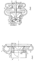
- Figure 6 is a cross-section through a multi-stage compressor in accordance with the present invention.
- Referring to Figure 1 there is shown a graph plotting pressure against mass flow in a single stage centrifugal compressor. The area between the lines D and E which is shown by shading, indicates a typical engine r.p.m. range over which a compressor not incorporating the present invention will operate. There is however a requirement to increase the engine r.p.m. range to cover an area between the lines D and B on the graph and it is therefore necessary to a;ter the characteristics of the compressor in order to move the surge line from the line marked S1 to the line marked S2. This can be achieved by use of the present invention. Similar results can be achieved with an axial compressor.
- Referring now to Figure 2, there is shown a cross-section view of a single stage centrifugal compressor comprising a
housing 10 having animpeller wheel 12 mounted in conventional manner for rotation therein. - The wheel indudes a plurality of blades or
vanes 14 of conventional design and each induding a leadingedge 16, atrailing edge 18 and an outerfree edge 20. The housing includes anouter wall 22, defining anintake 24 for gas such as air, and a passageway orpassageways 26 for carrying compressed gas from theimpeller wheel 12 to its destination e.g. the inlet manifold of an internal combustion engine. Aninner wall 28 defines aninlet 30 to the impeller and aninner surface 32 of saidinner wall 28 is in dose proximity to and of extremely similar contour to, the outerfree edges 20 of the blades orvanes 14. Theinner wall 28 extends a short distance upstream from theblades 14 of theimpeller wheel 12 whereby to form an annular space orchamber 34 between thewalls annular chamber 34 partly surrounds theimpeller wheel 12. Anannular slot 36 is formed in thewall 28 and a series ofwebs 38 serve to bridge the annular slot at intervals round its circumference. Theslot 36 is located along the meridional length (line A on the drawing) at a point just upstream of the point of minimum static pressure. This point is preferably some 65 to 75% of the distance from the leadingedges 16 of the blades or vanes 14 to the point of minimum static pressure and is typically 22 to 34% of the impeller blade length. In the arrangement shown in Figure 1 the slot is located some 73% of the distance from the leadingedge 16 of theblades 14 to the point of minimum static pressure and is 30% of the length of theimpeller blades 14 from the leadingedges 16 of the blades. - The total area of the slot is normally of the order of 13 to 23% of the inducer annular area In the arrangement shown the total area of the slot is 15% of the inducer annular area.
- In operation the
impeller wheel 12 is rotated e.g. by a turbine wheel (not shown) attached to a common axis with the compressor wheel and this causes air to be drawn into theimpeller wheel 12 throughintake 24 andinlet 30. The air is compressed by theimpeller wheel 12 and Is then fed to its ultimate destination via passageway orpassageways 26. The pressure in thechamber 34 is normally lower than atmospheric pressure and during high flow and high r.p.m. operation the pressure in the area swept by the impeller wheel is less than in thechamber 34 and thus air flows through theslot 36 from thechamber 34 to theimpeller wheel 12 thereby increasing the amount of air reaching the impeller wheel, and increasing its maximum flow capacity. As the flow through theimpeller wheel 12 drops or as r.p.m. of the impeller wheel drops so the amount of air drawn into thewheel 16 through theslot 36 decreases until equilibrium is reached. Further drop in impeller wheel flow or r.p.m. results in the pressure in the area swept by the impeller wheel being greater than in thechamber 34 and thus air flows through theslot 36 from theimpeller 12 to thechamber 34. The air bled out of theimpeller wheel 12 is recirculated to the air intake and thereby back to theinlet 30. Increase in flow or r.p.m. of the impeller wheel causes the reverse to happen, i.e. a decrease in the amount of air bled from the impeller wheel followed by equilibrium followed by air being drawn into theimpeller wheel 12 via theslot 36. This particular arrangement results in improved stability of the compressor at all speeds and a shift in the characteristics of the compressor. For example, the surge line is moved as shown in Figure 1 from S1 to S2 and the maximum flow capacity is moved from line F1 to F2 as shown in Figure 1. The compressor can thus be matched to engines with a wider speed range than can conventional compressors. - Referring now to Figure 3 there is shown an alternative embodiment in which the
slot 36 is replaced by a series ofholes 40. In this case there is of course no need for thewebs 38 of the arrangement of Figure 2. The positioning of theholes 40 along the meridional length and area of the holes at theinner surface 32 is similar to the positioning and area of theslot 36 in Figure 2. The number of holes should be arranged so that it is not equal to, nor a multiple of, nor a factor of the number of blades on the compressor wheel. If the number of holes is a multiple of or a factor of the number of blades then excitation can be induced. In the arrangement shown in Figure 3 the number ofholes 40 is 29 and the number of blades is 16. - Referring now to Figure 4 there is shown a further alternative embodiment of the invention in which the
chamber 34 is formed by a series ofblind bores 42 in the wall of the housing. The inner andouter walls bores 42. The bores may be connected either to an annular slot similar to slot 36 in Figure 2 or to a series of holes similar to thoseholes 40 in Figure 3. - Referring now to Figure 5 there is shown an arrangement In which the
chamber 34 is formed partly in thehousing 10 and partly by an annular slot 44 (with connecting webs) or series ofholes 44 formed in aring 46 which may be aluminium or plastic. Thechamber 34, as in other embodiments, communications with theimpeller wheel 12 via a series of holes or a slot. - Referring now to Figure 6, there is shown a multi-stage compressor, comprising an
axial compressor 100, and twocentrifugal compressors Axial compressor 100 indudes animpeller wheel 12 having a series of vanes orblades 106 each of which includes aleading edge 108, a trailingedge 110 and an outerfree edge 112. Air compressed bycompressor 100 is fed viaaxial outlet 114 to theinlet 116 ofcentrifugal compressor 102.Axial compressor 100 includes inner andouter walls chamber 34 as in the arrangement of Figures 2 and 3. In addition, a series of holes 40 (which could alternatively be a slot 36) is provided as in the device of Figure 3. Operation is similar to that of the device of Figures 2 and 3 with air bleeding from theimpeller wheel 12 to thechamber 34 near surge and with air being drawn from thechamber 34 to the impeller at high flow and high r.p.m. The twocentrifugal compressors 102. 104 are each individually similar to one of the compressors described in connection with one of Figures 2 to 5. The outlet fromcompressor 102 is connected to the inlet tocompressor 104.
Claims (10)
- A compressor comprising an impeller wheel (12) including a plurality of vanes or blades (14) each of which includes a leading edge (16), a trailing edge (18) and an outer free edge (20), said wheel (12) being mounted for rotation within a stationary housing (10), which housing (10) includes an inner wall (28) and an outer wall (22), at least part of the inner surface (32) of the inner wall (28) being in close proximity to, and of similar contour to, the outer free edges (20) of the blade or vanes (14), said outer wall (22) forming a gas intake (24) extending in an axial direction, said gas intake (24) surrounding said inner wall (28), said inner wall (28) forming an inlet (30) to said impeller wheel (12) in a region adjacent the leading edges (16) of said blades or vanes (14), a chamber (34) formed between said inner and outer walls (28 and 22) in a region at least partly surrounding said blades or vanes (14), a communication (36,40) being provided through said inner wall (28) between said chamber (34) and the inner surface of said inner wall (28), said communication (36,40) providing a bidirectional flowpath (36,40) through said inner wall (28), between said chamber (34) and the inner surface (32) of said inner wall (28) which flowpath is open at all times and gas movement in one direction or in the other direction through said flowpath (36,40) is in response to the pressure differential between said chamber (34) and the area swept by the vanes or blades (14), one end of said flowpath opening into the inner surface of the inner wall (28) at a position not more than 34% along the meridional length from the leading edge of the blades or vanes (14), and the total cross-sectional area of said opening of the flowpath (36,40) to the inner surface of the inner wall being at least 13% of the inducer annular area (i.e. the frontal area of the impeller wheel (12) at the leading edge minus of the hub area), and communication being provided between said gas intake (24) and said chamber (34), which communication is open at all times.
- A compressor as claimed in claim 1, characterised in that the bidirectional flowpath between the chamber (34) and the inner surface (32) of the inner wall (28) is an annular slot (36) extending around the inner wall and bridged by a series of connecting webs (38), or a plurality of holes (40).
- A compressor as claimed in claim 2, characterised in that the bidirectional flowpath comprises a plurality of holes (40) and the number of such holes (40) is not equal to, nor a multiple of, nor a factor of, the number of blades or vanes (14) of the impeller wheel (12).
- A compressor as claimed in claim 2 or 3, characterised in that the bidirectional flowpath comprises from twenty-nine to forty-three holes (40).
- A compressor as claimed in claim 2, 3 or 4, characterised in that the total area of the holes (40) or the slot (36) at the inner surface (32) of the inner wall (28) is from 13 to 23% of the inducer annular area (i.e. the frontal area of the impeller wheel (12) at the leading edge minus the hub area).
- A compressor as claimed in any one of claims 2 to 5, characterised in that the compressor is a centrifugal compressor and the holes (40) or slot (36) are located at a point along the meridional length just upstream of the point of minimum static pressure.
- A compressor as claimed in any one of claims 2 to 6, characterised in that the holes (40) or slot (36) are located at a point some 65 to 75% of the distance from the leading edge (16) of the blades (14) to the minimum static pressure point.
- A compressor as claimed in any one of claims 2 to 5, characterised in that the compressor is an axial compressor and the holes (40) or slots (36) are located some 15 to 25% along the length of the outer free edges (20) of the blades (14) from the leading edges.
- A multi-stage compressor characterised by comprising a number of compressors connected in a series so that the outlet from one compressor leads to the inlet of the next compressor in the series, in which one or more of the compressors in series is a compressor as claimed in any one of the preceding claims.
- A turbocharger for an internal combustion engine characterised by including a compressor as claimed in any one of the preceding claims.
Applications Claiming Priority (4)
| Application Number | Priority Date | Filing Date | Title |
|---|---|---|---|
| GB858531739A GB8531739D0 (en) | 1985-12-24 | 1985-12-24 | Compressors |
| GB868600884A GB8600884D0 (en) | 1986-01-15 | 1986-01-15 | Compressors |
| GB8600884 | 1986-01-15 | ||
| GB8531739 | 1986-01-15 |
Publications (3)
| Publication Number | Publication Date |
|---|---|
| EP0229519A1 EP0229519A1 (en) | 1987-07-22 |
| EP0229519B1 EP0229519B1 (en) | 1990-04-11 |
| EP0229519B2 true EP0229519B2 (en) | 1996-11-13 |
Family
ID=26290155
Family Applications (1)
| Application Number | Title | Priority Date | Filing Date |
|---|---|---|---|
| EP86310005A Expired - Lifetime EP0229519B2 (en) | 1985-12-24 | 1986-12-22 | Improvements in and relating to compressors |
Country Status (5)
| Country | Link |
|---|---|
| US (1) | US4743161A (en) |
| EP (1) | EP0229519B2 (en) |
| JP (1) | JP2569029B2 (en) |
| BR (1) | BR8606418A (en) |
| DE (1) | DE3670347D1 (en) |
Families Citing this family (95)
| Publication number | Priority date | Publication date | Assignee | Title |
|---|---|---|---|---|
| US4930979A (en) * | 1985-12-24 | 1990-06-05 | Cummins Engine Company, Inc. | Compressors |
| GB2202585B (en) * | 1987-03-24 | 1991-09-04 | Holset Engineering Co | Improvements in and relating to compressors |
| CH675279A5 (en) * | 1988-06-29 | 1990-09-14 | Asea Brown Boveri | |
| US4930978A (en) * | 1988-07-01 | 1990-06-05 | Household Manufacturing, Inc. | Compressor stage with multiple vented inducer shroud |
| US4981018A (en) * | 1989-05-18 | 1991-01-01 | Sundstrand Corporation | Compressor shroud air bleed passages |
| JPH02307719A (en) * | 1989-05-23 | 1990-12-20 | Mazda Motor Corp | Reaction injection mold |
| GB2234295B (en) * | 1989-07-21 | 1993-07-21 | Rolls Royce Plc | Gas turbine engine compressor assembly |
| JP2510350Y2 (en) * | 1989-11-07 | 1996-09-11 | 三菱重工業株式会社 | Centrifugal fluid machine |
| DE4027174A1 (en) * | 1990-08-28 | 1992-03-05 | Kuehnle Kopp Kausch Ag | MAP STABILIZATION WITH A RADIAL COMPRESSOR |
| US5257901A (en) * | 1990-12-28 | 1993-11-02 | Whirlpool Corporation | Quick-priming centrifugal pump |
| US5246335A (en) * | 1991-05-01 | 1993-09-21 | Ishikawajima-Harimas Jukogyo Kabushiki Kaisha | Compressor casing for turbocharger and assembly thereof |
| US5186601A (en) * | 1991-09-16 | 1993-02-16 | Sundstrand Corp. | Compressor shroud air bleed arrangement |
| US5236301A (en) * | 1991-12-23 | 1993-08-17 | Allied-Signal Inc. | Centrifugal compressor |
| US5304033A (en) * | 1992-07-20 | 1994-04-19 | Allied-Signal Inc. | Rotary compressor with stepped cover contour |
| JPH0630498U (en) * | 1992-09-18 | 1994-04-22 | 三菱重工業株式会社 | Shroud casing for centrifugal compressors |
| DE59206751D1 (en) * | 1992-10-17 | 1996-08-14 | Asea Brown Boveri | Stabilizing device for expanding the map of a compressor |
| JPH06147195A (en) * | 1992-10-30 | 1994-05-27 | Ishikawajima Harima Heavy Ind Co Ltd | Compressor housing of turbo charger |
| US5295785A (en) * | 1992-12-23 | 1994-03-22 | Caterpillar Inc. | Turbocharger having reduced noise emissions |
| CZ48394A3 (en) * | 1993-03-04 | 1994-09-14 | Abb Management Ag | Radial-flow compressor with a flow-stabilizing casing |
| GB2312929B (en) * | 1996-05-07 | 2000-08-23 | Inst Francais Du Petrole | Axial-flow and centrifugal pump system |
| GB2319809A (en) | 1996-10-12 | 1998-06-03 | Holset Engineering Co | An enhanced map width compressor |
| GB9722916D0 (en) * | 1997-10-31 | 1998-01-07 | Holset Engineering Co | Compressor |
| JPH11201094A (en) * | 1998-01-19 | 1999-07-27 | Ishikawajima Harima Heavy Ind Co Ltd | Turbo-compressor |
| US6183195B1 (en) | 1999-02-04 | 2001-02-06 | Pratt & Whitney Canada Corp. | Single slot impeller bleed |
| GB9918072D0 (en) | 1999-07-30 | 1999-10-06 | Alliedsignal Ltd | Turbocharger |
| US6290458B1 (en) | 1999-09-20 | 2001-09-18 | Hitachi, Ltd. | Turbo machines |
| DE10002581C2 (en) * | 2000-01-21 | 2002-01-17 | Man B & W Diesel Ag | turbocharger |
| DE60014025T2 (en) * | 2000-03-17 | 2006-02-16 | Hitachi, Ltd. | TURBOMASCHINEN |
| US6623239B2 (en) * | 2000-12-13 | 2003-09-23 | Honeywell International Inc. | Turbocharger noise deflector |
| US6699008B2 (en) | 2001-06-15 | 2004-03-02 | Concepts Eti, Inc. | Flow stabilizing device |
| US6669436B2 (en) | 2002-02-28 | 2003-12-30 | Dresser-Rand Company | Gas compression apparatus and method with noise attenuation |
| US7059820B2 (en) * | 2002-07-19 | 2006-06-13 | Honeywell International, Inc. | Noise control |
| EP1576291B1 (en) * | 2002-12-18 | 2016-08-31 | BSH Hausgeräte GmbH | Water-bearing domestic appliance comprising a drainage pump and corresponding drainage pump |
| US6918740B2 (en) * | 2003-01-28 | 2005-07-19 | Dresser-Rand Company | Gas compression apparatus and method with noise attenuation |
| EP1473465B2 (en) * | 2003-04-30 | 2018-08-01 | Holset Engineering Company Limited | Compressor |
| EP1473463B1 (en) * | 2003-04-30 | 2006-08-16 | Holset Engineering Co. Limited | Compressor |
| US6932563B2 (en) * | 2003-05-05 | 2005-08-23 | Honeywell International, Inc. | Apparatus, system and method for minimizing resonant forces in a compressor |
| US7025557B2 (en) * | 2004-01-14 | 2006-04-11 | Concepts Eti, Inc. | Secondary flow control system |
| US6945748B2 (en) * | 2004-01-22 | 2005-09-20 | Electro-Motive Diesel, Inc. | Centrifugal compressor with channel ring defined inlet recirculation channel |
| GB0403869D0 (en) * | 2004-02-21 | 2004-03-24 | Holset Engineering Co | Compressor |
| US6959552B2 (en) * | 2004-03-18 | 2005-11-01 | Pratt & Whitney Canada Corp. | Gas turbine inlet flow straightener |
| US7147426B2 (en) * | 2004-05-07 | 2006-12-12 | Pratt & Whitney Canada Corp. | Shockwave-induced boundary layer bleed |
| US7326027B1 (en) | 2004-05-25 | 2008-02-05 | The United States Of America As Represented By The Administrator Of The National Aeronautics And Space Administration | Devices and methods of operation thereof for providing stable flow for centrifugal compressors |
| KR101293678B1 (en) | 2005-02-23 | 2013-08-06 | 커민스 터보 테크놀러지스 리미티드 | Compressor |
| US8511083B2 (en) * | 2005-12-15 | 2013-08-20 | Honeywell International, Inc. | Ported shroud with filtered external ventilation |
| US7575411B2 (en) | 2006-05-22 | 2009-08-18 | International Engine Intellectual Property Company Llc | Engine intake air compressor having multiple inlets and method |
| EP2029896B1 (en) * | 2006-06-17 | 2011-08-17 | Cummins Turbo Technologies Ltd | Compressor |
| GB0701012D0 (en) | 2007-01-19 | 2007-02-28 | Cummins Turbo Tech Ltd | Compressor |
| GB0716060D0 (en) * | 2007-08-17 | 2007-09-26 | Cummins Turbo Technologies | An engine generator set |
| GB0718846D0 (en) | 2007-09-27 | 2007-11-07 | Cummins Turbo Tech Ltd | Compressor |
| GB0724701D0 (en) * | 2007-12-18 | 2008-01-30 | Cummins Turbo Tech Ltd | Compressor |
| US8546965B2 (en) * | 2008-01-15 | 2013-10-01 | Raymond Alvarez | Reduced pressure differential hydroelectric turbine system |
| JP5039673B2 (en) * | 2008-02-27 | 2012-10-03 | 三菱重工業株式会社 | Strut structure of turbo compressor |
| US8105012B2 (en) * | 2008-03-12 | 2012-01-31 | Opra Technologies B.V. | Adjustable compressor bleed system and method |
| US8061974B2 (en) * | 2008-09-11 | 2011-11-22 | Honeywell International Inc. | Compressor with variable-geometry ported shroud |
| WO2010028441A1 (en) * | 2008-09-11 | 2010-03-18 | Hunter Pacific International Pty Ltd | Extraction fan and rotor |
| DE102008047506A1 (en) | 2008-09-17 | 2010-04-15 | Daimler Ag | Radial compressor, in particular for an exhaust gas turbocharger of an internal combustion engine |
| CN102203429B (en) * | 2008-11-18 | 2015-05-20 | 博格华纳公司 | Compressor of an exhaust-gas turbocharger |
| DE102008061235B4 (en) * | 2008-12-09 | 2017-08-10 | Man Diesel & Turbo Se | Vibration reduction in an exhaust gas turbocharger |
| GB0823372D0 (en) | 2008-12-23 | 2009-01-28 | Cummins Turbo Tech Ltd | A compressor |
| GB2470050B (en) * | 2009-05-07 | 2015-09-23 | Cummins Turbo Tech Ltd | A compressor |
| US20110033287A1 (en) * | 2009-08-10 | 2011-02-10 | Lindner Bjoern Gerd | Blower scroll having an aspirator venturi |
| DE102009052162B4 (en) * | 2009-11-06 | 2016-04-14 | Mtu Friedrichshafen Gmbh | Compressor arrangement and method for producing such |
| DE102009054771A1 (en) * | 2009-12-16 | 2011-06-22 | Piller Industrieventilatoren GmbH, 37186 | Turbo compressor |
| US8882444B2 (en) | 2010-04-19 | 2014-11-11 | GM Global Technology Operations LLC | Compressor gas flow deflector and compressor incorporating the same |
| US9188129B2 (en) * | 2010-06-04 | 2015-11-17 | Borgwarner Inc. | Compressor of an exhaust-gas turbocharger |
| JP5533412B2 (en) * | 2010-08-05 | 2014-06-25 | 株式会社Ihi | Compressor |
| JP5533421B2 (en) * | 2010-08-16 | 2014-06-25 | 株式会社Ihi | Turbo compressor |
| US9429029B2 (en) | 2010-09-30 | 2016-08-30 | Pratt & Whitney Canada Corp. | Gas turbine blade and method of protecting same |
| US9587645B2 (en) | 2010-09-30 | 2017-03-07 | Pratt & Whitney Canada Corp. | Airfoil blade |
| US9567942B1 (en) * | 2010-12-02 | 2017-02-14 | Concepts Nrec, Llc | Centrifugal turbomachines having extended performance ranges |
| US9163516B2 (en) * | 2011-11-14 | 2015-10-20 | Concepts Eti, Inc. | Fluid movement system and method for determining impeller blade angles for use therewith |
| US9427835B2 (en) | 2012-02-29 | 2016-08-30 | Pratt & Whitney Canada Corp. | Nano-metal coated vane component for gas turbine engines and method of manufacturing same |
| CN104246169B (en) * | 2012-03-06 | 2018-01-23 | 博格华纳公司 | Exhaust turbine supercharger |
| EP2863064B1 (en) * | 2012-08-24 | 2019-06-05 | Mitsubishi Heavy Industries, Ltd. | Centrifugal compressor |
| JP5920127B2 (en) * | 2012-09-06 | 2016-05-18 | トヨタ自動車株式会社 | Supercharger deposit remover |
| KR101790421B1 (en) | 2013-01-23 | 2017-10-25 | 컨셉츠 이티아이 인코포레이티드 | Structures and methods for forcing coupling of flow fields of adjacent bladed elements of turbomachines, and turbomachines incorporating the same |
| US10125793B2 (en) | 2013-02-22 | 2018-11-13 | Mitsubishi Heavy Industries, Ltd. | Centrifugal compressor |
| US9726084B2 (en) * | 2013-03-14 | 2017-08-08 | Pratt & Whitney Canada Corp. | Compressor bleed self-recirculating system |
| GB201308381D0 (en) * | 2013-05-09 | 2013-06-19 | Imp Innovations Ltd | A modified inlet duct |
| US10107296B2 (en) * | 2013-06-25 | 2018-10-23 | Ford Global Technologies, Llc | Turbocharger systems and method to prevent compressor choke |
| KR101477420B1 (en) * | 2013-09-09 | 2014-12-29 | (주)계양정밀 | Turbocharger Compressor Having Air Current Part |
| CN113685377A (en) | 2014-06-24 | 2021-11-23 | 概创机械设计有限责任公司 | Flow control structure for turbomachine and design method thereof |
| JP6270083B2 (en) * | 2014-07-03 | 2018-01-31 | 三菱重工エンジン&ターボチャージャ株式会社 | Compressor cover, centrifugal compressor and turbocharger |
| JP6594019B2 (en) * | 2015-04-14 | 2019-10-23 | 三菱重工サーマルシステムズ株式会社 | Inlet guide vane and centrifugal compressor |
| KR102488570B1 (en) * | 2016-02-02 | 2023-01-13 | 한화파워시스템 주식회사 | Fluid machine |
| SE539728C2 (en) | 2016-03-17 | 2017-11-14 | Scania Cv Ab | A compressor arrangement supplying charged air to a combustion engine |
| JP6663269B2 (en) * | 2016-03-28 | 2020-03-11 | 株式会社日立製作所 | Compressor |
| US11092363B2 (en) | 2017-04-04 | 2021-08-17 | Danfoss A/S | Low back pressure flow limiter |
| US10935035B2 (en) * | 2017-10-26 | 2021-03-02 | Hanwha Power Systems Co., Ltd | Closed impeller with self-recirculation casing treatment |
| SE542728C2 (en) * | 2017-12-05 | 2020-06-30 | Scania Cv Ab | Compressor Housing, Turbocharger, and Related Devices |
| DE102018102704A1 (en) * | 2018-02-07 | 2019-08-08 | Man Energy Solutions Se | centrifugal compressors |
| CN110657125B (en) * | 2019-09-26 | 2020-12-11 | 成都凯天电子股份有限公司 | Method for improving cavitation resistance of impeller |
| DE102019133244A1 (en) * | 2019-12-05 | 2021-06-10 | Efficient Energy Gmbh | HEAT PUMP WITH IMPROVED STABILITY COMPRESSOR |
| US11828188B2 (en) | 2020-08-07 | 2023-11-28 | Concepts Nrec, Llc | Flow control structures for enhanced performance and turbomachines incorporating the same |
Family Cites Families (17)
| Publication number | Priority date | Publication date | Assignee | Title |
|---|---|---|---|---|
| GB589689A (en) * | 1944-03-31 | 1947-06-26 | British Thomson Houston Co Ltd | Improvements in and relating to centrifugal compressors |
| US2832292A (en) * | 1955-03-23 | 1958-04-29 | Edwards Miles Lowell | Pump assemblies |
| GB897575A (en) * | 1958-07-30 | 1962-05-30 | Sulzer Ag | Methods of and apparatus for preventing surging in single-stage or multi-stage radial flow compressors |
| CH404069A (en) * | 1962-06-29 | 1965-12-15 | Licentia Gmbh | Flow channel, in particular working medium flow channel of a turbo compressor |
| FR1344950A (en) * | 1962-09-04 | 1963-12-06 | Snecma | Centrifugal pump with peripheral inlet |
| DE1503581B1 (en) * | 1965-05-04 | 1970-12-17 | Maschf Augsburg Nuernberg Ag | Two-stroke internal combustion engine operated with exhaust gas turbocharging |
| FR1472085A (en) * | 1965-11-18 | 1967-03-10 | Snecma | Improvement in contra-rotary compressors |
| GB1153345A (en) * | 1966-06-20 | 1969-05-29 | Caterpillar Tractor Co | Imminent Separation Fluid Diffuser Passage |
| DE1815229A1 (en) * | 1968-12-17 | 1970-08-13 | Daimler Benz Ag | Blow-off device for a turbo machine |
| GB1342590A (en) * | 1970-07-17 | 1974-01-03 | Secr Defence | Suppression of noise in gas turbine engines |
| US3901620A (en) * | 1973-10-23 | 1975-08-26 | Howell Instruments | Method and apparatus for compressor surge control |
| US3887295A (en) * | 1973-12-03 | 1975-06-03 | Gen Motors Corp | Compressor inlet control ring |
| US3951566A (en) * | 1973-12-11 | 1976-04-20 | Electricite De France (Service National) | Axial-flow fan with by-pass pipe or pipes |
| US4212585A (en) * | 1978-01-20 | 1980-07-15 | Northern Research And Engineering Corporation | Centrifugal compressor |
| US4248566A (en) * | 1978-10-06 | 1981-02-03 | General Motors Corporation | Dual function compressor bleed |
| US4479755A (en) * | 1982-04-22 | 1984-10-30 | A/S Kongsberg Vapenfabrikk | Compressor boundary layer bleeding system |
| JPS60166799A (en) * | 1984-02-10 | 1985-08-30 | Ebara Corp | Centrifugal compressor |
-
1986
- 1986-12-22 DE DE8686310005T patent/DE3670347D1/en not_active Expired - Lifetime
- 1986-12-22 EP EP86310005A patent/EP0229519B2/en not_active Expired - Lifetime
- 1986-12-23 BR BR8606418A patent/BR8606418A/en not_active IP Right Cessation
- 1986-12-23 US US06/945,713 patent/US4743161A/en not_active Expired - Lifetime
- 1986-12-23 JP JP61316093A patent/JP2569029B2/en not_active Expired - Lifetime
Also Published As
| Publication number | Publication date |
|---|---|
| JPS62178799A (en) | 1987-08-05 |
| EP0229519A1 (en) | 1987-07-22 |
| BR8606418A (en) | 1987-10-13 |
| EP0229519B1 (en) | 1990-04-11 |
| US4743161A (en) | 1988-05-10 |
| DE3670347D1 (en) | 1990-05-17 |
| JP2569029B2 (en) | 1997-01-08 |
Similar Documents
| Publication | Publication Date | Title |
|---|---|---|
| EP0229519B2 (en) | Improvements in and relating to compressors | |
| US4930979A (en) | Compressors | |
| US4248566A (en) | Dual function compressor bleed | |
| US4981018A (en) | Compressor shroud air bleed passages | |
| US4463552A (en) | Combined surge bleed and dust removal system for a fan-jet engine | |
| EP1473465B2 (en) | Compressor | |
| EP1478857B1 (en) | Compressor with an anti-stall tip treatment | |
| US6973771B2 (en) | Diffuser for terrestrial or aviation gas turbine | |
| EP1473463B1 (en) | Compressor | |
| US4781530A (en) | Compressor range improvement means | |
| EP1157214B1 (en) | Compressor bleeding using an uninterrupted annular slot | |
| US6945748B2 (en) | Centrifugal compressor with channel ring defined inlet recirculation channel | |
| US4222703A (en) | Turbine engine with induced pre-swirl at compressor inlet | |
| US20060104805A1 (en) | Turbomachine with means for the creation of a peripheral jet on the stator | |
| EP1128070A2 (en) | Compressor | |
| US5313779A (en) | Surge protected gas turbine engine for providing variable bleed air flow | |
| GB2202585A (en) | Rotary non-positive displacement compressor | |
| EP0201770A2 (en) | Turbine engine with induced pre-swirl at the compressor inlet | |
| JP4012507B2 (en) | Double flow compressor | |
| US2958456A (en) | Multi-stage aerofoil-bladed compressors | |
| US4934139A (en) | Turbofan gas turbine engine | |
| JPS59168296A (en) | Surging preventive device of multistage axial-flow compressor | |
| EP2029896B1 (en) | Compressor | |
| CN112412873A (en) | Impeller with chordwise blade thickness variation |
Legal Events
| Date | Code | Title | Description |
|---|---|---|---|
| PUAI | Public reference made under article 153(3) epc to a published international application that has entered the european phase |
Free format text: ORIGINAL CODE: 0009012 |
|
| AK | Designated contracting states |
Kind code of ref document: A1 Designated state(s): DE FR GB SE |
|
| 17P | Request for examination filed |
Effective date: 19870921 |
|
| 17Q | First examination report despatched |
Effective date: 19880714 |
|
| GRAA | (expected) grant |
Free format text: ORIGINAL CODE: 0009210 |
|
| AK | Designated contracting states |
Kind code of ref document: B1 Designated state(s): DE FR GB SE |
|
| REF | Corresponds to: |
Ref document number: 3670347 Country of ref document: DE Date of ref document: 19900517 |
|
| ET | Fr: translation filed | ||
| PLBI | Opposition filed |
Free format text: ORIGINAL CODE: 0009260 |
|
| 26 | Opposition filed |
Opponent name: ABB PATENT GMBH Effective date: 19910111 |
|
| EAL | Se: european patent in force in sweden |
Ref document number: 86310005.3 |
|
| PLAW | Interlocutory decision in opposition |
Free format text: ORIGINAL CODE: EPIDOS IDOP |
|
| PLAW | Interlocutory decision in opposition |
Free format text: ORIGINAL CODE: EPIDOS IDOP |
|
| PUAH | Patent maintained in amended form |
Free format text: ORIGINAL CODE: 0009272 |
|
| STAA | Information on the status of an ep patent application or granted ep patent |
Free format text: STATUS: PATENT MAINTAINED AS AMENDED |
|
| 27A | Patent maintained in amended form |
Effective date: 19961113 |
|
| AK | Designated contracting states |
Kind code of ref document: B2 Designated state(s): DE FR GB SE |
|
| ET3 | Fr: translation filed ** decision concerning opposition | ||
| PGFP | Annual fee paid to national office [announced via postgrant information from national office to epo] |
Ref country code: SE Payment date: 19981207 Year of fee payment: 13 |
|
| PG25 | Lapsed in a contracting state [announced via postgrant information from national office to epo] |
Ref country code: SE Free format text: LAPSE BECAUSE OF NON-PAYMENT OF DUE FEES Effective date: 19991223 |
|
| EUG | Se: european patent has lapsed |
Ref document number: 86310005.3 |
|
| REG | Reference to a national code |
Ref country code: GB Ref legal event code: IF02 |
|
| PGFP | Annual fee paid to national office [announced via postgrant information from national office to epo] |
Ref country code: FR Payment date: 20051208 Year of fee payment: 20 |
|
| PGFP | Annual fee paid to national office [announced via postgrant information from national office to epo] |
Ref country code: DE Payment date: 20051215 Year of fee payment: 20 |
|
| PGFP | Annual fee paid to national office [announced via postgrant information from national office to epo] |
Ref country code: GB Payment date: 20051221 Year of fee payment: 20 |
|
| PG25 | Lapsed in a contracting state [announced via postgrant information from national office to epo] |
Ref country code: GB Free format text: LAPSE BECAUSE OF EXPIRATION OF PROTECTION Effective date: 20061221 |
|
| REG | Reference to a national code |
Ref country code: GB Ref legal event code: PE20 |