WO2016163519A1 - 合わせガラス用中間膜、合わせガラス、及び、合わせガラス用中間膜の製造方法 - Google Patents
合わせガラス用中間膜、合わせガラス、及び、合わせガラス用中間膜の製造方法 Download PDFInfo
- Publication number
- WO2016163519A1 WO2016163519A1 PCT/JP2016/061548 JP2016061548W WO2016163519A1 WO 2016163519 A1 WO2016163519 A1 WO 2016163519A1 JP 2016061548 W JP2016061548 W JP 2016061548W WO 2016163519 A1 WO2016163519 A1 WO 2016163519A1
- Authority
- WO
- WIPO (PCT)
- Prior art keywords
- laminated glass
- interlayer film
- shape
- laminated
- interlayer
- Prior art date
Links
Images


Classifications
-
- B—PERFORMING OPERATIONS; TRANSPORTING
- B32—LAYERED PRODUCTS
- B32B—LAYERED PRODUCTS, i.e. PRODUCTS BUILT-UP OF STRATA OF FLAT OR NON-FLAT, e.g. CELLULAR OR HONEYCOMB, FORM
- B32B17/00—Layered products essentially comprising sheet glass, or glass, slag, or like fibres
- B32B17/06—Layered products essentially comprising sheet glass, or glass, slag, or like fibres comprising glass as the main or only constituent of a layer, next to another layer of a specific material
- B32B17/10—Layered products essentially comprising sheet glass, or glass, slag, or like fibres comprising glass as the main or only constituent of a layer, next to another layer of a specific material of synthetic resin
- B32B17/10005—Layered products essentially comprising sheet glass, or glass, slag, or like fibres comprising glass as the main or only constituent of a layer, next to another layer of a specific material of synthetic resin laminated safety glass or glazing
- B32B17/1055—Layered products essentially comprising sheet glass, or glass, slag, or like fibres comprising glass as the main or only constituent of a layer, next to another layer of a specific material of synthetic resin laminated safety glass or glazing characterized by the resin layer, i.e. interlayer
- B32B17/10559—Shape of the cross-section
- B32B17/10577—Surface roughness
- B32B17/10587—Surface roughness created by embossing
-
- C—CHEMISTRY; METALLURGY
- C03—GLASS; MINERAL OR SLAG WOOL
- C03C—CHEMICAL COMPOSITION OF GLASSES, GLAZES OR VITREOUS ENAMELS; SURFACE TREATMENT OF GLASS; SURFACE TREATMENT OF FIBRES OR FILAMENTS MADE FROM GLASS, MINERALS OR SLAGS; JOINING GLASS TO GLASS OR OTHER MATERIALS
- C03C27/00—Joining pieces of glass to pieces of other inorganic material; Joining glass to glass other than by fusing
- C03C27/06—Joining glass to glass by processes other than fusing
- C03C27/10—Joining glass to glass by processes other than fusing with the aid of adhesive specially adapted for that purpose
-
- B—PERFORMING OPERATIONS; TRANSPORTING
- B32—LAYERED PRODUCTS
- B32B—LAYERED PRODUCTS, i.e. PRODUCTS BUILT-UP OF STRATA OF FLAT OR NON-FLAT, e.g. CELLULAR OR HONEYCOMB, FORM
- B32B3/00—Layered products comprising a layer with external or internal discontinuities or unevennesses, or a layer of non-planar form; Layered products having particular features of form
- B32B3/26—Layered products comprising a layer with external or internal discontinuities or unevennesses, or a layer of non-planar form; Layered products having particular features of form characterised by a particular shape of the outline of the cross-section of a continuous layer; characterised by a layer with cavities or internal voids ; characterised by an apertured layer
- B32B3/30—Layered products comprising a layer with external or internal discontinuities or unevennesses, or a layer of non-planar form; Layered products having particular features of form characterised by a particular shape of the outline of the cross-section of a continuous layer; characterised by a layer with cavities or internal voids ; characterised by an apertured layer characterised by a layer formed with recesses or projections, e.g. hollows, grooves, protuberances, ribs
-
- B—PERFORMING OPERATIONS; TRANSPORTING
- B32—LAYERED PRODUCTS
- B32B—LAYERED PRODUCTS, i.e. PRODUCTS BUILT-UP OF STRATA OF FLAT OR NON-FLAT, e.g. CELLULAR OR HONEYCOMB, FORM
- B32B17/00—Layered products essentially comprising sheet glass, or glass, slag, or like fibres
- B32B17/06—Layered products essentially comprising sheet glass, or glass, slag, or like fibres comprising glass as the main or only constituent of a layer, next to another layer of a specific material
- B32B17/10—Layered products essentially comprising sheet glass, or glass, slag, or like fibres comprising glass as the main or only constituent of a layer, next to another layer of a specific material of synthetic resin
- B32B17/10005—Layered products essentially comprising sheet glass, or glass, slag, or like fibres comprising glass as the main or only constituent of a layer, next to another layer of a specific material of synthetic resin laminated safety glass or glazing
- B32B17/1055—Layered products essentially comprising sheet glass, or glass, slag, or like fibres comprising glass as the main or only constituent of a layer, next to another layer of a specific material of synthetic resin laminated safety glass or glazing characterized by the resin layer, i.e. interlayer
-
- B—PERFORMING OPERATIONS; TRANSPORTING
- B29—WORKING OF PLASTICS; WORKING OF SUBSTANCES IN A PLASTIC STATE IN GENERAL
- B29C—SHAPING OR JOINING OF PLASTICS; SHAPING OF MATERIAL IN A PLASTIC STATE, NOT OTHERWISE PROVIDED FOR; AFTER-TREATMENT OF THE SHAPED PRODUCTS, e.g. REPAIRING
- B29C48/00—Extrusion moulding, i.e. expressing the moulding material through a die or nozzle which imparts the desired form; Apparatus therefor
- B29C48/001—Combinations of extrusion moulding with other shaping operations
- B29C48/002—Combinations of extrusion moulding with other shaping operations combined with surface shaping
-
- B—PERFORMING OPERATIONS; TRANSPORTING
- B29—WORKING OF PLASTICS; WORKING OF SUBSTANCES IN A PLASTIC STATE IN GENERAL
- B29C—SHAPING OR JOINING OF PLASTICS; SHAPING OF MATERIAL IN A PLASTIC STATE, NOT OTHERWISE PROVIDED FOR; AFTER-TREATMENT OF THE SHAPED PRODUCTS, e.g. REPAIRING
- B29C59/00—Surface shaping of articles, e.g. embossing; Apparatus therefor
- B29C59/02—Surface shaping of articles, e.g. embossing; Apparatus therefor by mechanical means, e.g. pressing
- B29C59/04—Surface shaping of articles, e.g. embossing; Apparatus therefor by mechanical means, e.g. pressing using rollers or endless belts
-
- B—PERFORMING OPERATIONS; TRANSPORTING
- B32—LAYERED PRODUCTS
- B32B—LAYERED PRODUCTS, i.e. PRODUCTS BUILT-UP OF STRATA OF FLAT OR NON-FLAT, e.g. CELLULAR OR HONEYCOMB, FORM
- B32B17/00—Layered products essentially comprising sheet glass, or glass, slag, or like fibres
-
- B—PERFORMING OPERATIONS; TRANSPORTING
- B32—LAYERED PRODUCTS
- B32B—LAYERED PRODUCTS, i.e. PRODUCTS BUILT-UP OF STRATA OF FLAT OR NON-FLAT, e.g. CELLULAR OR HONEYCOMB, FORM
- B32B17/00—Layered products essentially comprising sheet glass, or glass, slag, or like fibres
- B32B17/06—Layered products essentially comprising sheet glass, or glass, slag, or like fibres comprising glass as the main or only constituent of a layer, next to another layer of a specific material
- B32B17/10—Layered products essentially comprising sheet glass, or glass, slag, or like fibres comprising glass as the main or only constituent of a layer, next to another layer of a specific material of synthetic resin
- B32B17/10005—Layered products essentially comprising sheet glass, or glass, slag, or like fibres comprising glass as the main or only constituent of a layer, next to another layer of a specific material of synthetic resin laminated safety glass or glazing
- B32B17/10009—Layered products essentially comprising sheet glass, or glass, slag, or like fibres comprising glass as the main or only constituent of a layer, next to another layer of a specific material of synthetic resin laminated safety glass or glazing characterized by the number, the constitution or treatment of glass sheets
- B32B17/10036—Layered products essentially comprising sheet glass, or glass, slag, or like fibres comprising glass as the main or only constituent of a layer, next to another layer of a specific material of synthetic resin laminated safety glass or glazing characterized by the number, the constitution or treatment of glass sheets comprising two outer glass sheets
-
- B—PERFORMING OPERATIONS; TRANSPORTING
- B32—LAYERED PRODUCTS
- B32B—LAYERED PRODUCTS, i.e. PRODUCTS BUILT-UP OF STRATA OF FLAT OR NON-FLAT, e.g. CELLULAR OR HONEYCOMB, FORM
- B32B17/00—Layered products essentially comprising sheet glass, or glass, slag, or like fibres
- B32B17/06—Layered products essentially comprising sheet glass, or glass, slag, or like fibres comprising glass as the main or only constituent of a layer, next to another layer of a specific material
- B32B17/10—Layered products essentially comprising sheet glass, or glass, slag, or like fibres comprising glass as the main or only constituent of a layer, next to another layer of a specific material of synthetic resin
- B32B17/10005—Layered products essentially comprising sheet glass, or glass, slag, or like fibres comprising glass as the main or only constituent of a layer, next to another layer of a specific material of synthetic resin laminated safety glass or glazing
- B32B17/1055—Layered products essentially comprising sheet glass, or glass, slag, or like fibres comprising glass as the main or only constituent of a layer, next to another layer of a specific material of synthetic resin laminated safety glass or glazing characterized by the resin layer, i.e. interlayer
- B32B17/10761—Layered products essentially comprising sheet glass, or glass, slag, or like fibres comprising glass as the main or only constituent of a layer, next to another layer of a specific material of synthetic resin laminated safety glass or glazing characterized by the resin layer, i.e. interlayer containing vinyl acetal
-
- B—PERFORMING OPERATIONS; TRANSPORTING
- B32—LAYERED PRODUCTS
- B32B—LAYERED PRODUCTS, i.e. PRODUCTS BUILT-UP OF STRATA OF FLAT OR NON-FLAT, e.g. CELLULAR OR HONEYCOMB, FORM
- B32B27/00—Layered products comprising a layer of synthetic resin
- B32B27/06—Layered products comprising a layer of synthetic resin as the main or only constituent of a layer, which is next to another layer of the same or of a different material
- B32B27/08—Layered products comprising a layer of synthetic resin as the main or only constituent of a layer, which is next to another layer of the same or of a different material of synthetic resin
-
- B—PERFORMING OPERATIONS; TRANSPORTING
- B32—LAYERED PRODUCTS
- B32B—LAYERED PRODUCTS, i.e. PRODUCTS BUILT-UP OF STRATA OF FLAT OR NON-FLAT, e.g. CELLULAR OR HONEYCOMB, FORM
- B32B27/00—Layered products comprising a layer of synthetic resin
- B32B27/30—Layered products comprising a layer of synthetic resin comprising vinyl (co)polymers; comprising acrylic (co)polymers
- B32B27/306—Layered products comprising a layer of synthetic resin comprising vinyl (co)polymers; comprising acrylic (co)polymers comprising vinyl acetate or vinyl alcohol (co)polymers
-
- B—PERFORMING OPERATIONS; TRANSPORTING
- B32—LAYERED PRODUCTS
- B32B—LAYERED PRODUCTS, i.e. PRODUCTS BUILT-UP OF STRATA OF FLAT OR NON-FLAT, e.g. CELLULAR OR HONEYCOMB, FORM
- B32B3/00—Layered products comprising a layer with external or internal discontinuities or unevennesses, or a layer of non-planar form; Layered products having particular features of form
- B32B3/26—Layered products comprising a layer with external or internal discontinuities or unevennesses, or a layer of non-planar form; Layered products having particular features of form characterised by a particular shape of the outline of the cross-section of a continuous layer; characterised by a layer with cavities or internal voids ; characterised by an apertured layer
- B32B3/28—Layered products comprising a layer with external or internal discontinuities or unevennesses, or a layer of non-planar form; Layered products having particular features of form characterised by a particular shape of the outline of the cross-section of a continuous layer; characterised by a layer with cavities or internal voids ; characterised by an apertured layer characterised by a layer comprising a deformed thin sheet, i.e. the layer having its entire thickness deformed out of the plane, e.g. corrugated, crumpled
-
- B—PERFORMING OPERATIONS; TRANSPORTING
- B32—LAYERED PRODUCTS
- B32B—LAYERED PRODUCTS, i.e. PRODUCTS BUILT-UP OF STRATA OF FLAT OR NON-FLAT, e.g. CELLULAR OR HONEYCOMB, FORM
- B32B38/00—Ancillary operations in connection with laminating processes
- B32B38/06—Embossing
-
- B—PERFORMING OPERATIONS; TRANSPORTING
- B32—LAYERED PRODUCTS
- B32B—LAYERED PRODUCTS, i.e. PRODUCTS BUILT-UP OF STRATA OF FLAT OR NON-FLAT, e.g. CELLULAR OR HONEYCOMB, FORM
- B32B7/00—Layered products characterised by the relation between layers; Layered products characterised by the relative orientation of features between layers, or by the relative values of a measurable parameter between layers, i.e. products comprising layers having different physical, chemical or physicochemical properties; Layered products characterised by the interconnection of layers
- B32B7/02—Physical, chemical or physicochemical properties
-
- B—PERFORMING OPERATIONS; TRANSPORTING
- B32—LAYERED PRODUCTS
- B32B—LAYERED PRODUCTS, i.e. PRODUCTS BUILT-UP OF STRATA OF FLAT OR NON-FLAT, e.g. CELLULAR OR HONEYCOMB, FORM
- B32B7/00—Layered products characterised by the relation between layers; Layered products characterised by the relative orientation of features between layers, or by the relative values of a measurable parameter between layers, i.e. products comprising layers having different physical, chemical or physicochemical properties; Layered products characterised by the interconnection of layers
- B32B7/04—Interconnection of layers
- B32B7/12—Interconnection of layers using interposed adhesives or interposed materials with bonding properties
-
- B—PERFORMING OPERATIONS; TRANSPORTING
- B29—WORKING OF PLASTICS; WORKING OF SUBSTANCES IN A PLASTIC STATE IN GENERAL
- B29C—SHAPING OR JOINING OF PLASTICS; SHAPING OF MATERIAL IN A PLASTIC STATE, NOT OTHERWISE PROVIDED FOR; AFTER-TREATMENT OF THE SHAPED PRODUCTS, e.g. REPAIRING
- B29C48/00—Extrusion moulding, i.e. expressing the moulding material through a die or nozzle which imparts the desired form; Apparatus therefor
- B29C48/03—Extrusion moulding, i.e. expressing the moulding material through a die or nozzle which imparts the desired form; Apparatus therefor characterised by the shape of the extruded material at extrusion
- B29C48/07—Flat, e.g. panels
- B29C48/08—Flat, e.g. panels flexible, e.g. films
-
- B—PERFORMING OPERATIONS; TRANSPORTING
- B29—WORKING OF PLASTICS; WORKING OF SUBSTANCES IN A PLASTIC STATE IN GENERAL
- B29C—SHAPING OR JOINING OF PLASTICS; SHAPING OF MATERIAL IN A PLASTIC STATE, NOT OTHERWISE PROVIDED FOR; AFTER-TREATMENT OF THE SHAPED PRODUCTS, e.g. REPAIRING
- B29C48/00—Extrusion moulding, i.e. expressing the moulding material through a die or nozzle which imparts the desired form; Apparatus therefor
- B29C48/25—Component parts, details or accessories; Auxiliary operations
- B29C48/88—Thermal treatment of the stream of extruded material, e.g. cooling
- B29C48/919—Thermal treatment of the stream of extruded material, e.g. cooling using a bath, e.g. extruding into an open bath to coagulate or cool the material
-
- B—PERFORMING OPERATIONS; TRANSPORTING
- B29—WORKING OF PLASTICS; WORKING OF SUBSTANCES IN A PLASTIC STATE IN GENERAL
- B29K—INDEXING SCHEME ASSOCIATED WITH SUBCLASSES B29B, B29C OR B29D, RELATING TO MOULDING MATERIALS OR TO MATERIALS FOR MOULDS, REINFORCEMENTS, FILLERS OR PREFORMED PARTS, e.g. INSERTS
- B29K2029/00—Use of polyvinylalcohols, polyvinylethers, polyvinylaldehydes, polyvinylketones or polyvinylketals or derivatives thereof as moulding material
- B29K2029/14—Polyvinylacetals
-
- B—PERFORMING OPERATIONS; TRANSPORTING
- B32—LAYERED PRODUCTS
- B32B—LAYERED PRODUCTS, i.e. PRODUCTS BUILT-UP OF STRATA OF FLAT OR NON-FLAT, e.g. CELLULAR OR HONEYCOMB, FORM
- B32B2250/00—Layers arrangement
- B32B2250/40—Symmetrical or sandwich layers, e.g. ABA, ABCBA, ABCCBA
Definitions
- the present invention provides an interlayer film for laminated glass that can be easily peeled off even if stored in a laminated state, a laminated glass formed using the interlayer film for laminated glass, and an interlayer film for laminated glass It relates to a manufacturing method.
- Laminated glass obtained by sandwiching an interlayer film for laminated glass containing plasticized polyvinyl butyral between two glass plates and bonding them together is widely used particularly as a vehicle windshield.
- the recess has a groove shape with a continuous bottom, and the adjacent engraved recesses are regularly formed in parallel, thereby exhibiting extremely excellent deaeration. it can.
- a laminated glass obtained by cutting an interlayer film for laminated glass unwound from a roll into an appropriate size and sandwiching the interlayer film for laminated glass between at least two glass plates.
- the body is put in a rubber bag, sucked under reduced pressure, pre-pressed while deaerating the air remaining between the glass plate and the intermediate film, and then subjected to main pressing by heating and pressurizing in an autoclave, for example. Is called. (For example, Patent Document 1)
- an interlayer film for laminated glass that has been cut into a predetermined shape is laminated and stored in a constant temperature and humidity chamber.
- the interlayer films for laminated glass that are laminated during storage are adhered (self-attached) and cannot be peeled off by a machine that transports the interlayer film for laminated glass or by human power.
- the present invention provides an interlayer film for laminated glass that can be easily peeled off even when stored in a laminated state, a laminated glass using the interlayer film for laminated glass, and the laminated glass It aims at providing the manufacturing method of the intermediate film for glass.
- the present invention is an interlayer film for laminated glass having a large number of recesses on at least one surface, and the surface having the recesses has a surface arithmetic average roughness Sa measured in accordance with ISO 25178 of 200 nm or more. It is an interlayer film for laminated glass. The present invention is described in detail below.
- the interlayer film for laminated glass of the present invention has a large number of recesses on at least one surface. Thereby, the deaeration at the time of manufacture of a laminated glass is securable.
- the interlayer film for laminated glass of the present invention may have the concave portion only on one surface or both surfaces. Especially, since it is excellent in the deaeration at the time of laminated glass manufacture, it is preferable to have the said recessed part on both surfaces.
- the surface arithmetic mean roughness Sa measured based on ISO25178 is 200 nm or more.
- the above Sa is a three-dimensional image showing an arithmetic average height in a plane, which is calculated after image processing of an intermediate film surface image obtained by using a three-dimensional white light interference microscope and removing coarse irregularities.
- Shape parameter. That is, Sa is a parameter representing a fine uneven shape from which large unevenness has been removed (hereinafter, also referred to as “first shape” in order to distinguish it from a large uneven shape described later).
- the inventors of the present invention have found that the adhesive strength (self-adhesion) between the laminated glass interlayer films when the laminated interlayer films are stored is the surface of the laminated glass interlayer film. It has been found that the value of Sa is greatly affected. And as a result of further intensive studies, when the uneven shape of the surface of the interlayer film for laminated glass was controlled so that the value of Sa was 200 nm or more, it was easily attached without being attached even if stored in a laminated state. The present invention was completed by finding that it can be peeled off.
- the value of Sa is 200 nm or more, it can be easily peeled off without being attached even if stored in a laminated state. it can.
- the preferable lower limit of the value of Sa is 250 nm, and the more preferable lower limit is 400 nm.
- the upper limit of the value of Sa is not particularly limited, in order to ensure that the unevenness is crushed when the laminated glass is sandwiched between at least two glass plates and pressed together during the production of the laminated glass, About 3000 nm is a practical upper limit.
- the value of Sa of any one surface should just be 200 nm or more, but since the self-adhesion at the time of storing in the laminated state is suppressed further, It is preferable that the value of Sa is 200 nm or more.
- the Sa value can be measured by the following method, for example. That is, using a three-dimensional white light interference microscope (for example, ContourGT-K manufactured by Bruker AXS), the objective lens magnification is 115 times, the internal lens magnification is 0.5 times, and the resolution setting is Full resolution. Under such conditions, the surface of the interlayer film for laminated glass is measured with a 1 mm square field of view to obtain an image. At this time, the light amount and the threshold are set under appropriate conditions so that noise does not enter the measurement as much as possible.
- a three-dimensional white light interference microscope for example, ContourGT-K manufactured by Bruker AXS
- the objective lens magnification is 115 times
- the internal lens magnification is 0.5 times
- the resolution setting is Full resolution.
- the surface of the interlayer film for laminated glass is measured with a 1 mm square field of view to obtain an image.
- the light amount and the threshold are set under appropriate conditions so that noise does not enter the measurement as much as possible.
- the obtained image is subjected to a flattening process and a noise removal process, and after removing rough irregularities using a Guausian filter, a surface arithmetic average roughness Sa value is calculated by a method defined in ISO 25178.
- “Vision 64” which is analysis software attached to the apparatus was used.
- the flattening processing and noise removal processing conditions as the first processing, the “Terms Removal (F-Operator)” processing on the Analysis Toolbox is performed under the analysis condition “Tilt only (Plane Fit)”, and the second processing is performed.
- “Statistic Filter” processing is performed under the analysis conditions “Filter type: Sigma” and “Filter size: 5”, “data Restore” processing is selected as the analysis condition “Legacy”, and the RestoreEdge condition is selected, and the iteration condition Is set to a value that allows sufficient data interpolation.
- a “Gaussian Regression Filter” process is performed as a third process under the analysis condition “Short wavelength pass condition, order: 2, Type: Regular, Long wave length cutoff: 0.025 mm” and advanced Performed under conditions.
- Sa obtained as a result of performing the “S parameters-height” process under the analysis condition “Removal tilt: True” with the image data subjected to the first to third processes as the fourth process is the surface arithmetic average roughness. Sa value was used. Nine points are measured so that each measurement point is separated by 3 cm or more in a 10 cm square of the interlayer film for laminated glass to be a sample, and the average value is taken as the Sa value.
- the surface having the recesses preferably has a 10-point average roughness Rz measured in accordance with JIS B 0601 (1994) of 10 ⁇ m or more.
- Rz measured in accordance with JIS B 0601 (1994) of 10 ⁇ m or more.
- a more preferred lower limit of the Rz value is 15 ⁇ m, and a more preferred lower limit is 20 ⁇ m.
- the upper limit of the value of Rz is not particularly limited, but in order to ensure that the unevenness is crushed when the interlayer film for laminated glass is sandwiched between at least two glass plates and crimped, about 70 ⁇ m is substantial.
- the upper limit is 50 ⁇ m or less in order to more easily perform pressure bonding.
- the Rz can be measured, for example, by data processing of a digital signal measured using a surface roughness measuring instrument (SE1700 ⁇ manufactured by Kosaka Laboratory Ltd.).
- the method for imparting the first shape is not particularly limited, and examples thereof include an embossing roll method, a calender roll method, a profile extrusion method, and an extrusion lip embossing method using a melt fracture.
- fills desired Sa value (and Rz value) can be easily provided by using the following manufacture examples 1 or 2.
- Manufacturing Example 1 is a method using an embossing roll manufactured by a specific manufacturing method in the embossing roll method. That is, a step of forming irregularities by blasting using an abrasive on a metal roll (embossing roll manufacturing step 1) and a step of partially polishing the convex portions of the metal roll having irregularities to form a smooth surface (embossing) Embossing produced by a manufacturing process having a roll manufacturing process 2) and a process (embossing roll manufacturing process 3) for forming irregularities by blasting using a finer abrasive than the abrasive used in embossing roll manufacturing process 1
- a first shape is applied to the surface of the interlayer film for laminated glass using a roll.
- the metal roll used in the said embossing roll manufacturing process 1 consists of metals, such as iron, carbon steel, alloy steel, nickel chrome steel, chromium steel, for example. Especially, since it is excellent in durability, the metal roll which consists of carbon steel or alloy steel is suitable.
- the surface of the metal roll is blasted using an abrasive such as aluminum oxide or silicon oxide to form irregularities on the surface of the metal roll.
- an abrasive such as aluminum oxide or silicon oxide to form irregularities on the surface of the metal roll.
- aluminum oxide is suitable as the abrasive.
- the particle size of the abrasive used in the embossing roll production step 1 is preferably F20 to 120, more preferably F30 to 80, as defined by JIS R6001 (1998).
- the discharge pressure when performing the blasting process in the embossing roll manufacturing process 1 is generally 40 ⁇ 10 4 to 15 ⁇ 10 5 Pa, and the blasting process is performed until a desired roughness is obtained.
- corrugation in the said embossing roll manufacturing process 1 is partly grind
- the grinding wheel used for semi-polishing in the embossing roll manufacturing process 2 generally, JIS standard F200 to F220 or # 240 to # 2000 aluminum oxide or silicon carbide can be used, and # 400 to # 1000 are preferred. Used. Sandpaper can also be used as the grinding wheel.
- embossing roll manufacturing process 3 irregularities are formed by blasting using a finer abrasive than the abrasive used in the embossing roll manufacturing process 1.
- blasting is performed using an abrasive such as aluminum oxide or silicon oxide.
- the discharge pressure when performing the blasting process in the embossing roll manufacturing process 3 is generally 40 ⁇ 10 4 to 15 ⁇ 10 5 Pa.
- the particle size of the abrasive used in the embossing roll manufacturing step 3 is preferably F150 to F360 or # 240 to # 700 defined by JIS R6001 (1998), more preferably F220 or # 240 to # 400. preferable. By using an abrasive having such a particle size, the desired Sa value can be obtained.
- the abrasive used in the embossing roll manufacturing step 3 preferably has a 3% cumulative particle size of 150 ⁇ m or less, more preferably 120 ⁇ m or less, and 103 ⁇ m, according to JIS R6001 (1998). More preferably, it is as follows.
- the unevenness formed in the roll polishing part can be made fine, and the resulting Sa glass of the interlayer film for laminated glass becomes excessive. Can be prevented.
- the abrasive used in the embossing roll manufacturing step 3 preferably has a cumulative diameter of 94% in accordance with JIS R6001 (1998) having a particle diameter of 11 ⁇ m or more, and more preferably 20 ⁇ m or more. If the particle size at the 94% cumulative height is within the above preferred range, the irregularities formed on the roll polishing part can be made a certain level or more, and a laminated glass interlayer film having a large Sa value can be obtained.
- the abrasive used in the embossing roll manufacturing process 3 has a cumulative height of 3% according to JIS R6001 (1998) satisfying the above preferred range and a cumulative height according to JIS R6001 (1998). It is preferable that the particle size at the 94% point satisfies the above preferable range. In addition, as for the measuring method of the said particle size, the particle diameter of 3% of accumulated height, and the particle diameter of 94% of accumulated height, it is desirable to measure with an electrical resistance test method.
- the embossing roll may be subjected to metal plating for rust prevention.
- metal plating for rust prevention.
- chemical plating is preferable because uniform plating thickness can be obtained.
- the said 1st shape is provided to the surface of the intermediate film for laminated glasses by the embossing roll method using the embossing roll manufactured by the said manufacturing method.
- the conditions for the embossing roll method include, for example, conditions in which the film temperature is set to 80 ° C., the embossing roll temperature is set to 145 ° C., the linear velocity is set to 10 m / min, and the press linear pressure is set to a range of 1 to 100 kN / m. Can be mentioned.
- Production Example 2 is a method of adjusting the cooling rate after extruding a resin composition for forming an interlayer film for laminated glass as an interlayer film for laminated glass from a mold in an embossing method in which the melt fracture phenomenon is controlled. is there.
- the film extruded from the mold is cooled in a cooling water tank.
- the value (and Rz value) can be controlled. Specifically, for example, the Sa value (and Rz value) is increased by shortening the distance from the mold to the cooling water tank to increase the cooling rate of the film, and the desired Sa value (and Rz value). ) Satisfying the first shape.
- the distance from the mold to the cooling water tank is preferably 250 mm or less, more preferably 200 mm or less, still more preferably 100 mm or less, and most preferably 50 mm or less.
- the other preferable film forming conditions are as follows: the extrusion amount per mold width is 100 to 700 kg / hr ⁇ m, the film surface temperature immediately after coming out of the mold is 140 ° C. to 260 ° C., The resin pressure at the die entrance is 30 to 160 kgf / cm 2 , and the water temperature in the water tank for cooling the membrane is 20 ° C. to 30 ° C. Each condition is controlled to obtain the desired extrusion amount and Rz value.
- the interlayer film for laminated glass of the present invention preferably further has a larger concave portion than the fine concave portion in the first shape (hereinafter also referred to as “second shape”).
- second shape By having such a 2nd shape, the deaeration at the time of laminated glass manufacture can further be improved.
- the contact area between the films decreases during stacking storage, self-adhesion can be further prevented.
- the concave portion of the second shape only needs to have a shape (groove shape) in which at least the bottom portion is continuous.
- a shape groove shape
- an intermediate film for laminated glass generally in a line shape, a lattice shape (block shape, spherical shape), or the like.
- the shape of the recessed part provided to the surface of can be used.
- the shape of the concave portion may be a shape to which an embossing roll is transferred. It is preferable that the concave portion of the second shape has a groove shape with a continuous bottom portion, and the adjacent concave portions are arranged in parallel and regularly in parallel (hereinafter, also referred to as “inscribed line shape”).
- the ease of air release when a laminated body in which an interlayer film for laminated glass is laminated between two glass plates is closely related to the connectivity and smoothness of the bottom of the recess.
- the communication at the bottom is more excellent and the deaeration is remarkably improved.
- “regularly arranged in parallel” means that adjacent groove-shaped recesses may be arranged in parallel at equal intervals, and the adjacent engraved recesses in parallel may be arranged in parallel. However, it means that the intervals between all the adjacent engraved concave portions need not be equal.
- the shape of the groove may not be linear, and may be, for example, a wave shape or a zigzag shape.
- 1 and 2 are schematic views showing an example of an interlayer film for laminated glass in which groove-shaped concave portions are arranged in parallel at equal intervals.
- FIG. 3 is a schematic diagram showing an example of an interlayer film for laminated glass in which groove-shaped concave portions are not arranged at equal intervals but are arranged in parallel. In FIG. 3, the interval A between the recess 1 and the recess 2 is different from the interval B between the recess 1 and the recess 3.
- FIG. 3 is a schematic diagram showing an example of an interlayer film for laminated glass in which groove-shaped concave portions are not arranged at equal intervals but are arranged in parallel. In FIG. 3, the interval A between the recess 1 and the recess 2 is different from the interval B between the recess 1 and the recess 3.
- FIG. 4 is a schematic diagram showing an example of an interlayer film for laminated glass having a block-like shape on the surface
- FIG. 5 is a schematic diagram showing an example of an interlayer film for laminated glass having a spherical shape on the surface. Indicated.
- the preferable lower limit of the roughness (Rz) of the concave portion of the second shape is 10 ⁇ m, and the preferable upper limit is 75 ⁇ m.
- the more preferable lower limit of the roughness (Rz) is 15 ⁇ m, the more preferable upper limit is 50 ⁇ m, the still more preferable lower limit is 25 ⁇ m, and the still more preferable upper limit is 40 ⁇ m.
- the roughness of the recess was obtained by a method according to JIS B 0601 (1994) as defined in JIS B 0601 (1994) "Surface roughness-definition and indication”.
- the ten-point average roughness (Rz) of both surfaces of the interlayer film was measured.
- the environment during the measurement was 23 ° C. and 30 RH%.
- the direction in which the stylus was moved was perpendicular to the grooved groove direction.
- the interval Sm between the engraved concave portions is 400 ⁇ m or less. Preferably, it is 200 ⁇ m or less, more preferably 150 ⁇ m or less. A preferred lower limit is 80 ⁇ m.
- the interval Sm between the recesses can be measured, for example, by the following method. That is, the surface of the interlayer film for laminated glass (observation range: 4 mm ⁇ 4 mm) is observed using an optical microscope (for example, DSX-100, manufactured by OLYMPUS Co., Ltd.), and the shortest distance between the bottoms of adjacent concave portions observed. Measure all distances.
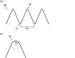
- FIG. 6A is a schematic diagram for explaining the interval Sm between the recesses.
- the unevenness 20 on the first surface or the second surface has a groove-shaped recess 21 having a continuous bottom and a protrusion 22.
- the interval Sm means the interval between the recesses 21.
- the concave portion of the second shape has a groove shape with a continuous bottom, the adjacent concave portions are arranged in parallel and regularly, and are on both surfaces of the interlayer film for laminated glass
- the crossing angle ⁇ between the groove-shaped recess having the bottom portion continuous on one surface and the groove-shaped recess having the bottom portion continuous on the other surface is 10 ° or more.
- the crossing angle ⁇ is more preferably 20 ° or more, further preferably 45 ° or more, and particularly preferably 90 °.
- FIG. 7 is a schematic diagram for explaining the intersection angle ⁇ . In FIG.
- the interlayer film 10 for laminated glass includes a groove-shaped concave portion 11 in which the bottom portion represented by a solid line is continuous on the first surface, and a groove-shaped concave portion in which the bottom portion represented by a dotted line is continuous on the second surface. Twelve.
- the crossing angle ⁇ represents the crossing angle between the groove-shaped concave portion 11 having a continuous bottom represented by a solid line and the groove-shaped concave portion 12 having a continuous bottom represented by a dotted line.
- the crossing angle ⁇ is, for example, a groove shape in which a bottom part of the first surface is continuous and a bottom part of the second surface is continuous by observing the interlayer film for laminated glass visually or with an optical microscope.
- the top part may be planar shape as shown in FIG. 1, and even if it is a shape which is not a plane as shown in FIG. Good.
- the top part of the said convex part is planar shape, a finer unevenness
- corrugation may be given to the plane of this top part.
- the heights of the convex portions of the concaves and convexes may be the same height or different heights, and the depth of the concave portions is the same as long as the bottom sides of the concave portions are continuous. Or a different depth.
- the rotation radius R of the convex portion is preferably 200 ⁇ m or less, more preferably 100 ⁇ m or less, still more preferably 40 ⁇ m or less, and particularly preferably 25 ⁇ m or less. Thereby, the adhesive force (self-adhesion force) of the interlayer films for laminated glass when the interlayer films for laminated glass are stored in a laminated state can be further reduced.
- the rotation radius R of the convex portion is, for example, that the intermediate film is cut in the direction perpendicular to the direction of the engraved concave portion and in the film thickness direction, and the cross section is taken into a microscope (for example, “DSX-” manufactured by Olympus).
- FIG. 6B is a schematic diagram for explaining the rotation radius R of the convex portion. In FIG. 6B, when a circle is drawn in contact with the tip of the convex portion 22, the radius of the circle is the rotation radius R of the convex portion.
- the surface arithmetic average roughness Sa (hereinafter also referred to as “head top portion Sa”) measured in accordance with ISO 25178 at the top of the convex portion is preferably 200 nm or more.
- the parietal portion Sa can be measured by the following method, for example. That is, using a three-dimensional white light interference microscope (for example, ContourGT-K manufactured by Bruker AXS), the objective lens magnification is 115 times, the internal lens magnification is 0.5 times, and the resolution setting is Full resolution. Under such conditions, the surface of the interlayer film for laminated glass is measured with a 1 mm square field of view to obtain an image.
- the light amount and the threshold are set under appropriate conditions so that noise does not enter the measurement as much as possible.
- the obtained image was subjected to a flattening process and a noise removal process, and height data for only the convex portion was extracted by a mask data process. After the rough unevenness is removed from the extracted data area by using a Guausian filter, the surface arithmetic average roughness Sa value is calculated by a method defined by ISO 25178. For the image processing, “Vision 64” which is analysis software attached to the apparatus was used.
- the “Terms Removal (F-Operator)” processing on the Analysis Toolbox is performed under the analysis condition “Tilt only (Plane Fit)”, and the second processing is performed.
- “Statistic Filter” processing is performed under the analysis conditions “Filter type: Sigma” and “Filter size: 5”
- “data Restore” processing is selected as the analysis condition “Legacy”
- the RestoreEdge condition is selected, and the iteration condition Is set to a value that allows sufficient data interpolation.
- the height of the histogram displayed under the Histogram Mask condition is between 0.2 and ⁇ 0.2 ⁇ m.
- the threshold value is determined, and height region data equal to or higher than the threshold value is extracted under the “Mask: Left” condition. Whether the threshold value can be set between 0.2 and ⁇ 0.2 ⁇ m can be confirmed from the histogram display of the post-extraction data.
- a “Gaussian Regression Filter” process is performed as a fourth process under the analysis condition “Short Wavelength Passage condition, order: 2, Type: Regular, Long wave length cutoff: 0.025 mm” and advance Performed under conditions.
- the image data subjected to the first to third processing is the fourth processing, and the “S parameters” -height processing is performed under the analysis condition “Removal tilt: True”. Sa value was used. Nine points are measured so that each measurement point is separated by 3 cm or more in a 10 cm square of the interlayer film for laminated glass to be a sample, and the average value is taken as the Sa value.
- the environment at the time of a measurement is under 23 degreeC and 30RH%.
- the method for imparting the second shape is not particularly limited, and examples thereof include an embossing roll method, a calender roll method, and a profile extrusion method.
- the embossing roll method is preferable because the shape in which the adjacent engraved concave portions are formed in parallel and the shape in parallel are easily obtained.
- the interlayer film for laminated glass of the present invention may have a single layer structure composed of only one resin layer or a multilayer structure in which two or more resin layers are laminated.
- the interlayer film for laminated glass of the present invention has a multilayer structure, it has a first resin layer and a second resin layer as two or more resin layers, and the first resin layer and the second resin layer Since the two resin layers have different properties, it is possible to provide an interlayer film for laminated glass having various performances that have been difficult to achieve with only one layer.
- the resin layer preferably contains a thermoplastic resin.
- the thermoplastic resin include polyvinylidene fluoride, polytetrafluoroethylene, vinylidene fluoride-hexafluoropropylene copolymer, polytrifluoride ethylene, acrylonitrile-butadiene-styrene copolymer, polyester, polyether, polyamide Polycarbonate, polyacrylate, polymethacrylate, polyvinyl chloride, polyethylene, polypropylene, polystyrene, polyvinyl acetal, ethylene-vinyl acetate copolymer and the like.
- the resin layer preferably contains polyvinyl acetal or ethylene-vinyl acetate copolymer, and more preferably contains polyvinyl acetal.
- the polyvinyl acetal can be produced, for example, by acetalizing polyvinyl alcohol with an aldehyde.
- the polyvinyl alcohol can be produced, for example, by saponifying polyvinyl acetate.
- the saponification degree of the polyvinyl alcohol is generally in the range of 70 to 99.8 mol%.
- the average degree of polymerization of the polyvinyl alcohol is preferably 200 or more, more preferably 500 or more, further preferably 1700 or more, particularly preferably more than 1700, preferably 5000 or less, more preferably 4000 or less, still more preferably 3000 or less, Particularly preferably, it is less than 3000.
- the average degree of polymerization is not less than the above lower limit, the penetration resistance of the laminated glass is further enhanced.
- the average degree of polymerization is not more than the above upper limit, the intermediate film can be easily molded.
- the average degree of polymerization of the polyvinyl alcohol is determined by a method based on JIS K6726 “Testing method for polyvinyl alcohol”.
- the number of carbon atoms of the acetal group contained in the polyvinyl acetal is not particularly limited.
- the aldehyde used when manufacturing the said polyvinyl acetal is not specifically limited.
- the preferable lower limit of the carbon number of the acetal group in the polyvinyl acetal is 3, and the preferable upper limit is 6.
- the carbon number of the acetal group in the polyvinyl acetal is 3 or more, the glass transition temperature of the intermediate film is sufficiently low, and bleeding out of the plasticizer can be prevented.
- the aldehyde having 3 to 6 carbon atoms may be a linear aldehyde or a branched aldehyde, and examples thereof include n-butyraldehyde and n-valeraldehyde. .
- the aldehyde is not particularly limited. In general, an aldehyde having 1 to 10 carbon atoms is preferably used as the aldehyde.
- Examples of the aldehyde having 1 to 10 carbon atoms include propionaldehyde, n-butyraldehyde, isobutyraldehyde, n-valeraldehyde, 2-ethylbutyraldehyde, n-hexylaldehyde, n-octylaldehyde, and n-nonylaldehyde.
- propionaldehyde, n-butyraldehyde, isobutyraldehyde, n-hexylaldehyde or n-valeraldehyde is preferable
- propionaldehyde, n-butyraldehyde or isobutyraldehyde is more preferable
- n-butyraldehyde is still more preferable.
- the said aldehyde only 1 type may be used and 2 or more types may be used together.
- the hydroxyl group content (hydroxyl group amount) of the polyvinyl acetal is preferably 10 mol% or more, more preferably 15 mol% or more, still more preferably 18 mol% or more, preferably 40 mol% or less, more preferably 35 mol%. It is as follows. When the hydroxyl group content is at least the above lower limit, the adhesive strength of the interlayer film is further increased. Further, when the hydroxyl group content is not more than the above upper limit, the flexibility of the interlayer film is increased, and the handling of the interlayer film is facilitated.
- the content ratio of the hydroxyl group of the polyvinyl acetal is a value obtained by dividing the amount of ethylene group to which the hydroxyl group is bonded by the total amount of ethylene group of the main chain, as a percentage.
- the amount of the ethylene group to which the hydroxyl group is bonded can be determined, for example, by measuring in accordance with JIS K6726 “Testing method for polyvinyl alcohol” or in accordance with ASTM D1396-92.
- the degree of acetylation (acetyl group amount) of the polyvinyl acetal is preferably 0.1 mol% or more, more preferably 0.3 mol% or more, still more preferably 0.5 mol% or more, preferably 30 mol% or less. More preferably, it is 25 mol% or less, More preferably, it is 20 mol% or less.
- the acetylation degree is not less than the above lower limit, the compatibility between the polyvinyl acetal and the plasticizer is increased.
- the acetylation degree is not more than the above upper limit, the moisture resistance of the interlayer film and the laminated glass is increased.
- the degree of acetylation is obtained by subtracting the amount of ethylene groups to which acetal groups are bonded and the amount of ethylene groups to which hydroxyl groups are bonded from the total amount of ethylene groups of the main chain, It is a value indicating the mole fraction obtained by dividing by the percentage.
- the amount of ethylene group to which the acetal group is bonded can be measured, for example, according to JIS K6728 “Testing method for polyvinyl butyral” or according to ASTM D1396-92.
- the degree of acetalization of the polyvinyl acetal is preferably 50 mol% or more, more preferably 53 mol% or more, still more preferably 60 mol% or more, and particularly preferably 63 mol%. As mentioned above, Preferably it is 85 mol% or less, More preferably, it is 75 mol% or less, More preferably, it is 70 mol% or less.
- the degree of acetalization is not less than the above lower limit, the compatibility between the polyvinyl acetal and the plasticizer increases.
- the degree of acetalization is not more than the above upper limit, the reaction time required for producing polyvinyl acetal is shortened.
- the degree of acetalization is a value indicating the mole fraction obtained by dividing the amount of ethylene groups to which acetal groups are bonded by the total amount of ethylene groups in the main chain, as a percentage.
- the degree of acetalization was determined by measuring the degree of acetylation and the hydroxyl group content by a method according to JIS K6728 “Testing methods for polyvinyl butyral” or a method according to ASTM D1396-92. The rate can be calculated and then calculated by subtracting the degree of acetylation and the hydroxyl content from 100 mol%.
- the hydroxyl group content (hydroxyl content), acetalization degree (butyralization degree), and acetylation degree are preferably calculated from results measured by a method in accordance with JIS K6728 “Testing methods for polyvinyl butyral”.
- the polyvinyl acetal is a polyvinyl butyral resin
- the hydroxyl group content (hydroxyl content), the degree of acetalization (degree of butyralization) and the degree of acetylation are measured by a method according to JIS K6728 “Testing methods for polyvinyl butyral”. It is preferable to calculate from the results.
- the resin layer preferably contains polyvinyl acetal and a plasticizer.
- the plasticizer is not particularly limited as long as it is a plasticizer generally used for an interlayer film for laminated glass.
- organic plasticizers such as monobasic organic acid esters and polybasic organic acid esters, organic Examples thereof include phosphoric acid plasticizers such as phosphoric acid compounds and organic phosphorous acid compounds.
- the organic plasticizer include triethylene glycol-di-2-ethylhexanoate, triethylene glycol-di-2-ethylbutyrate, triethylene glycol-di-n-heptanoate, and tetraethylene glycol-di-2.
- the resin layer preferably contains triethylene glycol-di-2-ethylhexanoate, triethylene glycol-di-2-ethylbutyrate, or triethylene glycol-di-n-heptanoate. More preferably, it contains ethylene glycol-di-2-ethylhexanoate.
- the content of the plasticizer is not particularly limited, but the content of the plasticizer with respect to 100 parts by mass of the thermoplastic resin is preferably 25 parts by mass or more, more preferably 30 parts by mass or more, preferably 80 parts by mass or less. More preferably, it is 70 mass parts or less.
- the content of the plasticizer is not less than the above lower limit, the penetration resistance of the laminated glass is further enhanced.
- the content of the plasticizer is not more than the above upper limit, the transparency of the interlayer film is further enhanced.
- the resin layer preferably contains an adhesive strength modifier.
- the resin layer that comes into contact with the glass preferably contains the above-mentioned adhesive strength modifier.
- an alkali metal salt or alkaline-earth metal salt is used suitably, for example.
- salts, such as potassium, sodium, magnesium are mentioned, for example.
- the acid constituting the salt include organic acids of carboxylic acids such as octylic acid, hexyl acid, 2-ethylbutyric acid, butyric acid, acetic acid and formic acid, or inorganic acids such as hydrochloric acid and nitric acid. Since the adhesive force of glass and a resin layer can be prepared easily when manufacturing a laminated glass, it is preferable that the resin layer which contacts glass contains a magnesium salt as an adhesive force regulator.
- the resin layer contains additives such as a modified silicone oil, a flame retardant, an antistatic agent, a moisture resistant agent, a heat ray reflective agent, and a heat ray absorbent as necessary, as an antioxidant, a light stabilizer, and an adhesion modifier. May be.
- additives such as a modified silicone oil, a flame retardant, an antistatic agent, a moisture resistant agent, a heat ray reflective agent, and a heat ray absorbent as necessary, as an antioxidant, a light stabilizer, and an adhesion modifier. May be.
- the thickness of the interlayer film for laminated glass of the present invention is not particularly limited. From the viewpoint of practical use and from the viewpoint of sufficiently increasing the heat shielding property, the thickness of the intermediate film is preferably 0.1 mm or more, more preferably 0.25 mm or more, preferably 3 mm or less, more preferably 1.5 mm or less. is there. When the thickness of the intermediate film is not less than the above lower limit, the penetration resistance of the laminated glass is increased.
- the method for producing the interlayer film for laminated glass of the present invention is not particularly limited.
- a conventionally known method can be used as a method for producing the intermediate film.
- the manufacturing method etc. which knead
- the interlayer film for laminated glass of the present invention has at least a first resin layer and a second resin layer as two or more resin layers, and is a polyvinyl acetal (hereinafter referred to as polyvinyl acetal) contained in the first resin layer. It is preferable that the amount of hydroxyl group of acetal A) is different from the amount of hydroxyl group of polyvinyl acetal (hereinafter referred to as polyvinyl acetal B) contained in the second resin layer. Since the properties of polyvinyl acetal A and polyvinyl acetal B are different, it is possible to provide an interlayer film for laminated glass having various performances that have been difficult to achieve with only one layer.
- the first resin layer when the first resin layer is laminated between two layers of the second resin layer and the amount of hydroxyl group of polyvinyl acetal A is lower than the amount of hydroxyl group of polyvinyl acetal B, The resin layer tends to have a lower glass transition temperature than the second resin layer. As a result, the first resin layer is softer than the second resin layer, and the sound insulation of the interlayer film for laminated glass is increased. Further, when the first resin layer is laminated between the two second resin layers and the amount of hydroxyl groups of the polyvinyl acetal A is higher than the amount of hydroxyl groups of the polyvinyl acetal B, the first resin layer The resin layer tends to have a higher glass transition temperature than the second resin layer. As a result, the first resin layer is harder than the second resin layer, and the penetration resistance of the interlayer film for laminated glass is increased.
- the content of the plasticizer (hereinafter referred to as content A) with respect to 100 parts by mass of the polyvinyl acetal in the first resin layer.
- the plasticizer content in the second resin layer is preferably different from that of 100 parts by mass of polyvinyl acetal (hereinafter referred to as “content B”).
- content A the content of the plasticizer
- content B the content of the polyvinyl acetal
- the first resin layer When the first resin layer is laminated between the two second resin layers and the content A is less than the content B, the first resin layer is The glass transition temperature tends to be higher than that of the second resin layer. As a result, the first resin layer is harder than the second resin layer, and the penetration resistance of the interlayer film for laminated glass is increased.
- the sound insulation layer as the first resin layer and the second resin layer A combination with a protective layer may be used as the resin layer.
- the sound insulating layer contains polyvinyl acetal X and a plasticizer
- the protective layer contains polyvinyl acetal Y and a plasticizer because the sound insulating properties of the laminated glass are improved.
- an interlayer film for laminated glass hereinafter, also referred to as a sound insulation interlayer
- a sound insulation interlayer an interlayer film for laminated glass having excellent sound insulation can be obtained.
- the sound insulating interlayer will be described more specifically.
- the sound insulating layer has a role of providing sound insulating properties.
- the sound insulation layer preferably contains polyvinyl acetal X and a plasticizer.
- the polyvinyl acetal X can be prepared by acetalizing polyvinyl alcohol with an aldehyde.
- the polyvinyl alcohol is usually obtained by saponifying polyvinyl acetate.
- the preferable lower limit of the average degree of polymerization of the polyvinyl alcohol is 200, and the preferable upper limit is 5000.
- the average degree of polymerization of the polyvinyl alcohol By setting the average degree of polymerization of the polyvinyl alcohol to 200 or more, the penetration resistance of the obtained sound insulating interlayer can be improved, and by setting it to 5000 or less, the moldability of the sound insulating layer can be ensured.
- the more preferable lower limit of the average degree of polymerization of the polyvinyl alcohol is 500, and the more preferable upper limit is 4000.
- the average degree of polymerization of the polyvinyl alcohol is determined by a method based on JIS K6726 “Testing method for polyvinyl alcohol”.
- the preferable lower limit of the carbon number of the aldehyde for acetalizing the polyvinyl alcohol is 4, and the preferable upper limit is 6.
- the aldehyde having 4 to 6 carbon atoms may be a linear aldehyde or a branched aldehyde, and examples thereof include n-butyraldehyde and n-valeraldehyde. .
- the upper limit with the preferable amount of hydroxyl groups of the said polyvinyl acetal X is 30 mol%.
- the more preferable upper limit of the hydroxyl group amount of the polyvinyl acetal X is 28 mol%, the more preferable upper limit is 26 mol%, the particularly preferable upper limit is 24 mol%, the preferable lower limit is 10 mol%, the more preferable lower limit is 15 mol%, and the more preferable lower limit. Is 20 mol%.
- the amount of hydroxyl groups in the polyvinyl acetal X is a value obtained by dividing the amount of ethylene groups to which the hydroxyl groups are bonded by the total amount of ethylene groups in the main chain, as a percentage (mol%).
- the amount of the ethylene group to which the hydroxyl group is bonded can be determined, for example, by measuring the amount of ethylene group to which the hydroxyl group of the polyvinyl acetal X is bonded by a method based on JIS K6728 “Testing method for polyvinyl butyral”. it can.
- the minimum with the preferable amount of acetal groups of the said polyvinyl acetal X is 60 mol%, and a preferable upper limit is 85 mol%.
- a preferable upper limit is 85 mol%.
- the lower limit of the amount of acetal group of the polyvinyl acetal X is more preferably 65 mol%, still more preferably 68 mol% or more.
- the amount of the acetal group can be determined by measuring the amount of ethylene group to which the acetal group of the polyvinyl acetal X is bonded by a method based on JIS K6728 “Testing method for polyvinyl butyral”.
- the minimum with the preferable amount of acetyl groups of the said polyvinyl acetal X is 0.1 mol%, and a preferable upper limit is 30 mol%.
- a preferable upper limit is 30 mol%.
- the more preferable lower limit of the acetyl group amount is 1 mol%, the more preferable lower limit is 5 mol%, the particularly preferable lower limit is 8 mol%, the more preferable upper limit is 25 mol%, and the still more preferable upper limit is 20 mol%.
- the amount of acetyl groups is the value obtained by subtracting the amount of ethylene groups to which acetal groups are bonded and the amount of ethylene groups to which hydroxyl groups are bonded from the total amount of ethylene groups in the main chain. This is a value expressed as a percentage (mol%) of the mole fraction obtained by dividing by.
- the above-mentioned sound insulation layer can easily contain a plasticizer in an amount necessary to exhibit sound insulation
- the above-mentioned polyvinyl acetal X is a polyvinyl acetal having an acetyl group content of 8 mol% or more, or Polyvinyl acetal having an acetyl group amount of less than 8 mol% and an acetal group amount of 65 mol% or more is preferred.
- the polyvinyl acetal X is a polyvinyl acetal having an acetyl group amount of 8 mol% or more, or a polyvinyl acetal having an acetyl group amount of less than 8 mol% and an acetal group amount of 68 mol% or more. More preferable.
- the preferable minimum with respect to 100 mass parts of said polyvinyl acetals X is 45 mass parts, and a preferable upper limit is 80 mass parts.
- a preferable upper limit is 80 mass parts.
- the more preferred lower limit of the plasticizer content is 50 parts by mass
- the still more preferred lower limit is 55 parts by mass
- the more preferred upper limit is 75 parts by mass
- the still more preferred upper limit is 70 parts by mass.
- a preferable lower limit of the thickness is 50 ⁇ m.
- a more preferable lower limit of the thickness of the sound insulation layer is 80 ⁇ m.
- an upper limit is not specifically limited, Considering the thickness as an interlayer film for laminated glass, a preferable upper limit is 300 ⁇ m.
- the sound insulation layer may have one end and the other end opposite to the one end, and the other end may have a shape larger than the thickness of the one end.
- the sound insulation layer preferably has a portion having a wedge-shaped cross-sectional shape in the thickness direction.
- a preferable lower limit of the minimum thickness of the sound insulation layer is 50 ⁇ m. By setting the minimum thickness of the sound insulation layer to 50 ⁇ m or more, sufficient sound insulation can be exhibited.
- a more preferable lower limit of the minimum thickness of the sound insulating layer is 80 ⁇ m, and a more preferable lower limit is 100 ⁇ m.
- the upper limit of the maximum thickness of the said sound-insulating layer is not specifically limited, Considering the thickness as an intermediate film for laminated glasses, a preferable upper limit is 300 micrometers. A more preferable upper limit of the maximum thickness of the sound insulation layer is 220 ⁇ m.
- the above-mentioned protective layer prevents bleeding of a large amount of plasticizer contained in the sound insulation layer, resulting in a decrease in the adhesion between the interlayer film for laminated glass and the glass. Has the role of granting.
- the protective layer preferably contains, for example, polyvinyl acetal Y and a plasticizer, and more preferably contains polyvinyl acetal Y having a larger amount of hydroxyl group than polyvinyl acetal X and a plasticizer.
- the polyvinyl acetal Y can be prepared by acetalizing polyvinyl alcohol with an aldehyde.
- the polyvinyl alcohol is usually obtained by saponifying polyvinyl acetate.
- the preferable minimum of the average degree of polymerization of the said polyvinyl alcohol is 200, and a preferable upper limit is 5000.
- the more preferable lower limit of the average degree of polymerization of the polyvinyl alcohol is 500, and the more preferable upper limit is 4000.
- the preferable lower limit of the carbon number of the aldehyde for acetalizing the polyvinyl alcohol is 3, and the preferable upper limit is 4.
- the aldehyde having 3 to 4 carbon atoms may be a linear aldehyde or a branched aldehyde, and examples thereof include n-butyraldehyde.
- the upper limit with the preferable amount of hydroxyl groups of the said polyvinyl acetal Y is 33 mol%, and a preferable minimum is 28 mol%.
- the preferable lower limit of the amount of acetal group is 60 mol%, and the preferable upper limit is 80 mol%.
- the amount of the acetal group is 60 mol% or more, an amount of plasticizer necessary for exhibiting sufficient penetration resistance can be contained.
- the amount of the acetal group 80 mol% or less it is possible to ensure the adhesive force between the protective layer and the glass.
- a more preferable lower limit of the amount of the acetal group is 65 mol%, and a more preferable upper limit is 69 mol%.
- the upper limit with the preferable amount of acetyl groups of the said polyvinyl acetal Y is 7 mol%.
- the amount of acetyl groups of the polyvinyl acetal Y 7 mol% or less the hydrophobicity of the protective layer can be increased and whitening can be prevented.
- a more preferable upper limit of the amount of the acetyl group is 2 mol%, and a preferable lower limit is 0.1 mol%.
- the amount of hydroxyl groups, the amount of acetal groups, and the amount of acetyl groups of polyvinyl acetals A, B, and Y can be measured by the same method as that for polyvinyl acetal X.
- the preferable minimum with respect to 100 mass parts of said polyvinyl acetals Y is 20 mass parts, and a preferable upper limit is 45 mass parts.
- a preferable upper limit is 45 mass parts.
- the more preferred lower limit of the plasticizer content is 30 parts by mass
- the still more preferred lower limit is 35 parts by mass
- the more preferred upper limit is 43 parts by mass
- the still more preferred upper limit is 41 parts by mass. Since the sound insulation of the laminated glass is further improved, the plasticizer content in the protective layer is preferably smaller than the plasticizer content in the sound insulation layer.
- the amount of hydroxyl group of the polyvinyl acetal Y is preferably larger than the amount of hydroxyl group of the polyvinyl acetal X, more preferably 1 mol% or more, further preferably 5 mol% or more. It is particularly preferably 8 mol% or more.
- the content of the plasticizer (hereinafter also referred to as content X) relative to 100 parts by mass of the polyvinyl acetal X100 in the sound insulation layer is the polyvinyl acetal Y100 in the protective layer. It is preferably more than the content of plasticizer (hereinafter also referred to as “content Y”) relative to parts by mass, more preferably 5 parts by mass or more, still more preferably 15 parts by mass or more, and more than 20 parts by mass. It is particularly preferred.
- the glass transition temperature of the sound insulation layer is lowered. As a result, the sound insulation of the laminated glass is further improved.
- the thickness of the protective layer is not particularly limited as long as it is adjusted to a range that can serve as the protective layer. However, when the protective layer has irregularities, it is preferable to increase the thickness as much as possible so as to prevent the irregularities from being transferred to the interface with the sound insulating layer that is in direct contact therewith. Specifically, when the cross-sectional shape of the protective layer is rectangular, the preferable lower limit of the thickness of the protective layer is 100 ⁇ m, the more preferable lower limit is 200 ⁇ m, the still more preferable lower limit is 300 ⁇ m, the particularly preferable lower limit is 400 ⁇ m, and the most preferable. The lower limit is 450 ⁇ m.
- the upper limit of the thickness of the protective layer is not particularly limited, but in order to ensure the thickness of the sound insulating layer to such an extent that sufficient sound insulating properties can be achieved, the upper limit is substantially about 500 ⁇ m.
- the protective layer may have one end and the other end opposite to the one end, and the thickness of the other end may be larger than the thickness of the one end.
- the protective layer preferably has a portion having a wedge-shaped cross-sectional shape in the thickness direction.
- the thickness of the protective layer is not particularly limited as long as it is adjusted to a range that can serve as the protective layer. However, when the protective layer has irregularities, it is preferable to increase the thickness as much as possible so as to prevent the irregularities from being transferred to the interface with the sound insulating layer that is in direct contact therewith.
- a preferable lower limit of the minimum thickness of the protective layer is 100 ⁇ m, a more preferable lower limit is 300 ⁇ m, a still more preferable lower limit is 400 ⁇ m, and a particularly preferable lower limit is 450 ⁇ m.
- the upper limit of the maximum thickness of the protective layer is not particularly limited, but in order to ensure the thickness of the sound insulation layer to the extent that sufficient sound insulation can be achieved, the upper limit is substantially about 1000 ⁇ m, and preferably 800 ⁇ m. .
- the interlayer film for laminated glass of the present invention may have one end and the other end opposite to the one end.
- the one end and the other end are end portions on both sides facing each other in the intermediate film.
- the thickness of the other end is preferably larger than the thickness of the one end.
- the wedge-shaped wedge angle ⁇ can be adjusted according to the mounting angle of the laminated glass to enable image display that prevents the occurrence of double images in the head-up display. It becomes.
- the preferable lower limit of the wedge angle ⁇ is 0.1 mrad
- the more preferable lower limit is 0.2 mrad
- the still more preferable lower limit is 0.3 mrad
- the preferable upper limit is 1 mrad
- the more preferable upper limit is 0.9 mrad.
- an interlayer film for laminated glass having a wedge-shaped cross section is manufactured by a method of extruding a resin composition using an extruder, a slightly inner region (specifically, from one end on the thin side) , Where X is the distance between one end and the other end, and has a minimum thickness in the range from 0X to 0.2X inward from one end on the thin side, and one end on the thick side
- the maximum thickness in the region slightly inside specifically, when the distance between one end and the other end is X, the region from 0X to 0.2X inward from one end on the thick side
- It may become the shape which has. In the present specification, such a shape is also included in the wedge shape.
- the method for producing the sound insulation interlayer is not particularly limited.For example, after the sound insulation layer and the protective layer are formed into a sheet by a normal film formation method such as an extrusion method, a calendar method, and a press method, The method of laminating etc. is mentioned.
- the laminated glass in which the interlayer film for laminated glass of the present invention is laminated between a pair of glass plates is also one aspect of the present invention.
- the said glass plate can use the transparent plate glass generally used. Examples thereof include inorganic glass such as float plate glass, polished plate glass, template glass, netted glass, wire-containing plate glass, colored plate glass, heat ray absorbing glass, heat ray reflecting glass, and green glass. Further, an ultraviolet shielding glass having an ultraviolet shielding coating layer on the glass surface can also be used. Furthermore, organic plastics plates such as polyethylene terephthalate, polycarbonate, and polyacrylate can also be used. Two or more types of glass plates may be used as the glass plate. For example, the laminated glass which laminated
- an intermediate film for laminated glass that can be easily peeled off without being attached even when stored in a laminated state, a laminated glass using the intermediate film for laminated glass, and the intermediate for laminated glass A method for manufacturing a membrane can be provided.
- Example 1 Preparation of resin composition Polyvinyl butyral obtained by acetalizing polyvinyl alcohol having an average degree of polymerization of 1700 with n-butyraldehyde (acetyl group amount 1 mol%, butyral group amount 69.1 mol%, hydroxyl group) Amount of 30 mol%) To 100 parts by mass, 40 parts by mass of triethylene glycol-di-2-ethylhexanoate (3GO) is added as a plasticizer and kneaded thoroughly with a mixing roll to obtain a resin composition. It was.
- 3GO triethylene glycol-di-2-ethylhexanoate
- the embossing roll manufactured by the following method was used.
- blasting was performed on a metal roll surface at a discharge pressure of 50 ⁇ 10 4 Pa using an abrasive # 36 made of aluminum oxide.
- the 10-point average roughness Rz of the roll surface after the embossing roll production process 1 was measured according to JIS B 0601 (1994), and it was 65 ⁇ m.
- semi-polishing was performed using a # 400 to 1000 polishing grindstone.
- the 10-point average roughness Rz of the roll surface after the embossing roll production process 1 was measured according to JIS B 0601 (1994), and it was 40 ⁇ m.
- blasting was performed at a discharge pressure of 50 ⁇ 10 4 Pa using an abrasive # 320 made of aluminum oxide.
- the roll which made the obtained embossing roll a pair was used as an uneven
- the temperature of the interlayer film for laminated glass is 80 ° C.
- the temperature of the roll is 145 ° C.
- the linear velocity is 10 m / min
- the line width is 1.5 m
- the press linear pressure is 1 to 100 kN / m. It was adjusted so that the desired roughness could be obtained.
- the thickness of the obtained laminated glass interlayer film was 760 ⁇ m.
- “Vision 64” which is analysis software attached to the apparatus was used.
- the “Terms Removal (F-Operator)” processing on the Analysis Toolbox is performed under the analysis condition “Tilt only (Plane Fit)”, and the second processing is performed.
- “Statistic Filter” processing is performed under the analysis conditions “Filter type: Sigma” and “Filter size: 5”
- “data Restore” processing is selected as the analysis condition “Legacy”
- the RestoreEdge condition is selected, and the iteration condition Is set to a value that allows sufficient data interpolation.
- the height of the histogram displayed under the Histogram Mask condition is between 0.2 and ⁇ 0.2 ⁇ m.
- the threshold value is determined, and height region data equal to or higher than the threshold value is extracted under the “Mask: Left” condition.
- a “Gaussian Regression Filter” process is performed as a fourth process under the analysis condition “Short Wavelength Passage condition, order: 2, Type: Regular, Long wave length cutoff: 0.025 mm” and advance Performed under conditions.
- the image data subjected to the first to third processing is the fourth processing, and the “S parameters” -height processing is performed under the analysis condition “Removal tilt: True”. Sa value was used. Nine points were measured in a 10 cm square of the interlayer film for laminated glass so that each measurement point was separated by 3 cm or more, and the average value was taken as the Sa value.
- Example 2 and 3 Comparative Examples 1 and 2 Example except that the type of blasting agent used in the embossing roll manufacturing process 3 used for manufacturing the embossing roll in the provision of the first shape and the pressing pressure at the time of transferring the concavo-convex shape were adjusted so as to obtain the desired Rz value.
- Example 1 an interlayer film for laminated glass was produced, and the unevenness on both sides thereof was measured.
- Example 4 Preparation of resin composition Polyvinyl butyral obtained by acetalizing polyvinyl alcohol having an average degree of polymerization of 1700 with n-butyraldehyde (acetyl group amount 1 mol%, butyral group amount 69.1 mol%, hydroxyl group) Amount of 30 mol%) To 100 parts by mass, 40 parts by mass of triethylene glycol-di-2-ethylhexanoate (3GO) is added as a plasticizer and kneaded thoroughly with a mixing roll to obtain a resin composition. It was.
- 3GO triethylene glycol-di-2-ethylhexanoate
- the temperature of the interlayer film for laminated glass was adjusted to 70 ° C., the roll temperature to 140 ° C., the linear velocity to 10 m / min, and the press linear pressure to 1 to 100 kN / m.
- the same operation was performed on the second surface of the interlayer film for laminated glass to give a groove-shaped recess having a continuous bottom.
- the intersection angle between the groove-shaped (engraved) concave portion with the bottom applied to the first surface and the groove-shaped (engraved) concave portion with the bottom applied to the second surface is It was set to 20 °.
- the thickness of the obtained laminated glass interlayer film was 760 ⁇ m.
- the surface of the interlayer film for laminated glass was measured with a 1 mm square field of view to obtain an image.
- the obtained image was subjected to a flattening process and a noise removal process, and height data for only the convex portion was extracted by a mask data process.
- the surface arithmetic average roughness Sa value is calculated by a method defined by ISO 25178.
- “Vision 64” which is analysis software attached to the apparatus was used.
- the “Terms Removal (F-Operator)” processing on the Analysis Toolbox is performed under the analysis condition “Tilt only (Plane Fit)”, and the second processing is performed.
- “Statistic Filter” processing is performed under the analysis conditions “Filter type: Sigma” and “Filter size: 5”
- “data Restore” processing is selected as the analysis condition “Legacy”
- the RestoreEdge condition is selected, and the iteration condition Is set to a value that allows sufficient data interpolation.
- the height of the histogram displayed under the Histogram Mask condition is between 0.2 and ⁇ 0.2 ⁇ m.
- the threshold value is determined, and height region data equal to or higher than the threshold value is extracted under the “Mask: Left” condition.
- a “Gaussian Regression Filter” process is performed as a fourth process under the analysis condition “Short Wavelength Passage condition, order: 2, Type: Regular, Long wave length cutoff: 0.025 mm” and advance Performed under conditions.
- the image data subjected to the first to third processing is the fourth processing, and the “S parameters” -height processing is performed under the analysis condition “Removal tilt: True”. Sa value was used. Nine points were measured in a 10 cm square of the interlayer film for laminated glass so that each measurement point was separated by 3 cm or more, and the average value was taken as the Sa value.
- “Statistic Filter” processing is performed under the analysis conditions “Filter type: Sigma” and “Filter size: 5”
- “data Restore” processing is selected as the analysis condition “Legacy”
- the RestoreEdge condition is selected, and the iteration condition Is set to a value that allows sufficient data interpolation.
- the height of the histogram displayed under the Histogram Mask condition is between 0.2 and ⁇ 0.2 ⁇ m.
- the threshold value is determined, and height region data equal to or higher than the threshold value is extracted under the “Mask: Left” condition.
- a “Gaussian Regression Filter” process is performed as a fourth process under the analysis condition “Short Wavelength Passage condition, order: 2, Type: Regular, Long wave length cutoff: 0.025 mm” and advance Performed under conditions.
- the image data subjected to the first to third processing is the fourth processing, and the “S parameters” -height processing is performed under the analysis condition “Removal tilt: True”.
- Sa value was used. Nine points were measured in a 10 cm square of the interlayer film for laminated glass so that each measurement point was separated by 3 cm or more, and the average value was taken as the Sa value.
- the intermediate film is cut in a direction perpendicular to the direction of the engraved concave parts and in the film thickness direction, and the cross section is cut into a microscope (for example, “Olympus” DSX-100 "), the image was taken at a measurement magnification of 277 times, and the photographed image was enlarged and displayed at 50 ⁇ / 20 mm.
- the rotation radius R of the convex portion was measured by a method in which the radius of the circle when drawing a circle inscribed at the apex of the shape was the rotational radius of the tip of the convex portion.
- the environment during the measurement was 23 ° C. and 30 RH%.
- Example 5 to 8 The type of fine blasting agent used in the embossing roll manufacturing process 3 used for manufacturing the embossing roll in the first shape application is changed as shown in Table 1, and the embossed shape and pitch width in the second shape application are shown in Table 1.
- the press linear pressure in the application of the second shape was adjusted in the range of 1 to 100 kN / m so as to obtain the desired roughness.
- An interlayer film for glass was produced, and the unevenness on both sides thereof was measured.
- the self-adhesion strength of the interlayer films for laminated glass obtained in Examples 1 to 8 and Comparative Examples 1 and 2 was evaluated by the following method. The results are shown in Table 1.
- the interlayer film for laminated glass obtained in Examples and Comparative Examples was cut into a size of 150 mm length and 150 mm width to obtain a test piece. Two obtained test pieces were stacked, and a glass plate (weight 5.8 kg) was placed on the base paper through a release paper having a silicone coating applied thereto as a release treatment. In this state, it was left for 48 hours in a constant temperature and humidity layer adjusted to a temperature of 30 ° C. and a humidity of 30%.
- the self-adhesion force is 20 N / 15 cm or less, more preferably 13 N / 15 cm or less, and more preferably 10 N / 15 cm or less for a machine for transporting the interlayer film for laminated glass or for manual peeling. More preferably it is.
- Example 9 (1) Preparation of resin composition Polyvinyl butyral obtained by acetalizing polyvinyl alcohol having an average degree of polymerization of 1700 with n-butyraldehyde (acetyl group amount 1 mol%, butyral group amount 69.1 mol%, hydroxyl group) Amount of 30 mol%) To 100 parts by mass, 40 parts by mass of triethylene glycol-di-2-ethylhexanoate (3GO) is added as a plasticizer and kneaded thoroughly with a mixing roll to obtain a resin composition. It was.
- 3GO triethylene glycol-di-2-ethylhexanoate
- die at this time to the surface of a cooling water tank was 50 mm.
- the thickness of the obtained interlayer film for laminated glass was 760 ⁇ m. Further, the Sa value and the Rz value were measured by the same method as in Example 1.
- Example 10 and 11 Comparative Example 3
- An interlayer film for laminated glass was produced in the same manner as in Example 9 except that the distance from the mold to the surface of the cooling water tank in the application of the first shape was as shown in Table 2, and measurement of unevenness on both sides thereof Went.
- Example 12 (1) Preparation of resin composition Polyvinyl butyral obtained by acetalizing polyvinyl alcohol having an average degree of polymerization of 1700 with n-butyraldehyde (acetyl group amount 1 mol%, butyral group amount 69.1 mol%, hydroxyl group) Amount of 30 mol%) To 100 parts by mass, 40 parts by mass of triethylene glycol-di-2-ethylhexanoate (3GO) is added as a plasticizer and kneaded thoroughly with a mixing roll to obtain a resin composition. It was.
- 3GO triethylene glycol-di-2-ethylhexanoate
- the temperature of the interlayer film for laminated glass was adjusted to 70 ° C., the roll temperature to 140 ° C., the linear velocity to 10 m / min, and the press linear pressure to 1 to 100 kN / m.
- the same operation was performed on the second surface of the interlayer film for laminated glass to give a groove-shaped recess having a continuous bottom.
- the intersection angle between the groove-shaped (engraved) concave portion with the bottom applied to the first surface and the groove-shaped (engraved) concave portion with the bottom applied to the second surface is It was set to 20 °.
- the unevenness of the first surface and the second surface was measured by the same method as in Example 4.
- Example 13 to 16 Comparative Examples 4 to 6
- the distance from the mold in the first shape application to the surface of the cooling water tank is changed as shown in Table 2
- the embossed shape and the pitch width in the second shape application are changed as shown in Table 2
- an interlayer film for laminated glass was produced in the same manner as in Example 12 except that the press linear pressure in the application of the second shape was adjusted in the range of 1 to 100 kN / m so as to obtain the desired roughness. The unevenness on both sides was measured.
- Example 17 and 18 The composition of the polyvinyl butyral used is changed to the composition shown in Table 3, and the type of blasting agent used in the embossing roll manufacturing process 3 used for manufacturing the embossing roll in the provision of the first shape and the pressing pressure at the time of transferring the uneven shape are determined.
- An interlayer film for laminated glass was produced in the same manner as in Example 1 except that the Rz value of the period was adjusted, and the unevenness on both sides thereof was measured.
- Example 19 to 21 The composition of polyvinyl butyral used is changed to the composition shown in Table 3, and the type of fine blasting agent used in the embossing roll manufacturing process 3 used for manufacturing the embossing roll in the provision of the first shape is changed as shown in Table 3, The emboss shape and pitch width in the second shape application are changed as shown in Table 3, and the press linear pressure in the second shape application is 1 to 100 kN / m so that the desired roughness can be obtained.
- An interlayer film for laminated glass was produced in the same manner as in Example 4 except that the adjustment was made in the above range, and the unevenness on both sides thereof was measured.
- Example 22 and 23 The composition of the polyvinyl butyral used was changed to the composition shown in Table 4, and the distance from the mold to the surface of the cooling water tank in the application of the first shape was as shown in Table 4 in the same manner as in Example 9. An interlayer film for laminated glass was produced, and the unevenness on both sides thereof was measured.
- Example 24 The composition of polyvinyl butyral used is changed to the composition shown in Table 4, the distance from the mold in the provision of the first shape to the surface of the cooling water tank is changed as shown in Table 4, and the embossing in the provision of the second shape Except for changing the shape and pitch width as shown in Table 4, and further adjusting the press linear pressure in the application of the second shape in the range of 1 to 100 kN / m so as to obtain the desired roughness.
- An interlayer film for laminated glass was produced in the same manner as in Example 12, and the unevenness on both sides thereof was measured.
- Example 25 (Preparation of resin composition for protective layer) For 100 parts by mass of polyvinyl butyral (acetyl group amount 1 mol%, butyral group amount 69 mol%, hydroxyl group amount 30 mol%) obtained by acetalizing polyvinyl alcohol having an average polymerization degree of 1700 with n-butyraldehyde Then, 36 parts by mass of triethylene glycol-di-2-ethylhexanoate (3GO) was added as a plasticizer. The mixture was sufficiently kneaded with a mixing roll to obtain a protective layer resin composition.
- polyvinyl butyral acetyl group amount 1 mol%, butyral group amount 69 mol%, hydroxyl group amount 30 mol%
- 3GO triethylene glycol-di-2-ethylhexanoate
- the obtained intermediate layer resin composition and protective layer resin composition are coextruded using a coextrusion machine, whereby the first protective layer and the intermediate layer resin composition are formed of the protective layer resin composition.
- An interlayer film for laminated glass having a three-layer structure in which the intermediate layer made of the above and the second protective layer made of the resin composition for the protective layer were laminated in this order was obtained.
- extrusion conditions were set so that the thickness of a 1st protective layer and a 2nd protective layer might be 350 micrometers, respectively, and the thickness of an intermediate
- Example 26 Comparative Examples 7 to 8 Example except that the type of blasting agent used in the embossing roll manufacturing process 3 used for manufacturing the embossing roll in the provision of the first shape and the pressing pressure at the time of transferring the concavo-convex shape were adjusted so as to obtain the desired Rz value.
- Example 26 Comparative Examples 7 to 8 Example except that the type of blasting agent used in the embossing roll manufacturing process 3 used for manufacturing the embossing roll in the provision of the first shape and the pressing pressure at the time of transferring the concavo-convex shape were adjusted so as to obtain the desired Rz value.
- an interlayer film for laminated glass was produced, and the unevenness on both sides thereof was measured.
- Example 27 Example except that the type of blasting agent used in the embossing roll manufacturing process 3 used for manufacturing the embossing roll in the provision of the first shape and the pressing pressure at the time of transferring the concavo-convex shape were adjusted so as to obtain the desired Rz value. In the same manner as in No. 25, an interlayer film for laminated glass was produced to give the first shape.
- groove-shaped irregularities having a continuous bottom were provided by the following procedure.
- Laminated glass provided with the first shape using a pair of rolls consisting of a metal roll milled on a surface using a triangular diagonal mill and a rubber roll having a JIS hardness of 45 to 75 as a concavo-convex shape transfer device
- the intermediate film for use was passed through this uneven shape transfer device, and the first surface of the intermediate film for laminated glass was provided with unevenness formed at equal intervals in parallel with a groove shape having a continuous bottom.
- the temperature of the interlayer film for laminated glass was adjusted to 70 ° C., the roll temperature to 140 ° C., the linear velocity to 10 m / min, and the press linear pressure to 1 to 100 kN / m.
- the same operation was performed on the second surface of the interlayer film for laminated glass to give a groove-shaped recess having a continuous bottom.
- the intersection angle between the groove-shaped (engraved) concave portion with the bottom applied to the first surface and the groove-shaped (engraved) concave portion with the bottom applied to the second surface is It was set to 20 °.
- Examples 28 to 33 Comparative Example 9
- the composition of the polyvinyl butyral used is changed to the composition shown in Tables 6 and 7, and the types of the fine blasting agent used in the embossing roll manufacturing step 3 used for manufacturing the embossing roll in the provision of the first shape are shown in Tables 6 and 7.
- the emboss shape and pitch width in the second shape application are changed as shown in Tables 6 and 7, and the second shape application is performed to obtain the desired roughness.
- An interlayer film for laminated glass was produced in the same manner as in Example 27 except that the press linear pressure was adjusted in the range of 1 to 100 kN / m, and the unevenness on both sides thereof was measured.
- Example 34 A resin composition for an intermediate layer and a resin composition for a protective layer were obtained in the same manner as in Example 25 except that the composition of polyvinyl butyral used was changed to the composition shown in Table 8.
- the obtained intermediate layer resin composition and protective layer resin composition are coextruded using a coextrusion machine, whereby the first protective layer and the intermediate layer resin composition are formed of the protective layer resin composition.
- An interlayer film for laminated glass having a three-layer structure in which the intermediate layer made of the above and the second protective layer made of the resin composition for the protective layer were laminated in this order was obtained. In that case, according to the said manufacture example 2, the 1st shape was provided simultaneously with forming the intermediate film for laminated glasses.
- the extrusion amount per mold width is 440 kg / hr ⁇ m
- the film surface temperature immediately after exiting the mold is 200 ° C.
- the resin pressure at the die entrance is 80 kgf / cm. 2.
- An interlayer film for laminated glass was formed at the same time as the water temperature in the water tank for cooling the film was 20 ° C. to 30 ° C., and at the same time, the first shape was imparted to both surfaces thereof.
- die at this time to the surface of a cooling water tank was 100 mm.
- the thickness of the first protective layer and the second protective layer of the obtained interlayer film for laminated glass was 350 ⁇ m
- the thickness of the intermediate layer was 100 ⁇ m. Further, the Sa value and the Rz value were measured by the same method as in Example 1.
- Examples 35 and 36, Comparative Example 10 An interlayer film for laminated glass was produced in the same manner as in Example 34 except that the distance from the mold to the surface of the cooling water tank in the application of the first shape was as shown in Table 8, and measurement of irregularities on both surfaces thereof was performed. Went.
- Example 37 (Production of interlayer film for laminated glass and provision of first shape) In the same manner as in Example 34, an interlayer film for laminated glass was formed, and at the same time, the first shape was imparted.
- groove-shaped irregularities having a continuous bottom were provided by the following procedure.
- Laminated glass provided with the first shape using a pair of rolls consisting of a metal roll milled on a surface using a triangular diagonal mill and a rubber roll having a JIS hardness of 45 to 75 as a concavo-convex shape transfer device
- the intermediate film for use was passed through this uneven shape transfer device, and the first surface of the intermediate film for laminated glass was provided with unevenness formed at equal intervals in parallel with a groove shape having a continuous bottom.
- the temperature of the interlayer film for laminated glass was adjusted to 70 ° C., the roll temperature to 140 ° C., the linear velocity to 10 m / min, and the press linear pressure to 1 to 100 kN / m.
- the same operation was performed on the second surface of the interlayer film for laminated glass to give a groove-shaped recess having a continuous bottom.
- the intersection angle between the groove-shaped (engraved) concave portion with the bottom applied to the first surface and the groove-shaped (engraved) concave portion with the bottom applied to the second surface is It was set to 20 °.
- the unevenness of the first surface and the second surface was measured by the same method as in Example 4.
- Example 38 Comparative Example 11
- the composition of polyvinyl butyral used is changed to the composition shown in Table 9, the distance from the mold in the provision of the first shape to the surface of the cooling water tank is changed as shown in Table 9, and the embossing in the provision of the second shape Except for changing the shape and pitch width as shown in Table 9, and further adjusting the press linear pressure in the application of the second shape in the range of 1 to 100 kN / m so as to obtain the desired roughness.
- An interlayer film for laminated glass was produced in the same manner as in Example 37, and the unevenness on both sides thereof was measured.
- an intermediate film for laminated glass that can be easily peeled off without being attached even when stored in a laminated state, a laminated glass using the intermediate film for laminated glass, and the intermediate for laminated glass A method for manufacturing a membrane can be provided.
Abstract
Description
以下に本発明を詳述する。
本発明の合わせガラス用中間膜は、上記凹部を一方の表面にのみ有してもよく、両方の表面に有してもよい。なかでも、合わせガラス製造時における脱気性に優れることから、上記凹部を両方の表面に有することが好ましい。
上記Saは、3次元白色光干渉型顕微鏡を用いて得られた中間膜表面の画像を画像処理して、粗大な凹凸を除去したうえで算出する、面内の算術平均高さを示す3次元形状パラメータ-である。即ち、Saは、大きな凹凸を除去した、微細な凹凸形状を表すパラメータである(以下、後述する大きな凹凸形状と区別するために、「第1の形状」ともいう)。本発明の発明者らは、鋭意検討の結果、合わせガラス用中間膜を積層した状態で保管したときの合わせガラス用中間膜同士の接着力(自着力)が、合わせガラス用中間膜の表面の上記Saの値に大きく影響を受けることを見出した。そして更に鋭意検討した結果、該Saの値が200nm以上となるように合わせガラス用中間膜の表面の凹凸形状を制御した場合には、積層した状態で保管しても自着せずに、容易に剥離可能となることを見出し、本発明を完成した。
上記Saの値の上限は特に限定されないが、合わせガラスの製造時に合わせガラス用中間膜を少なくとも2枚のガラス板の間に挟持して圧着した際に、確実に凹凸が潰れるようにするためには、3000nm程度が実質的な上限である。
なお、両面に上記凹部を有する場合には、どちらか一方の面のSaの値が200nm以上であればよいが、積層した状態で保管した場合の自着がより一層抑えられることから、両面のSaの値が200nm以上であることが好ましい。
即ち、3次元白色光干渉型顕微鏡(例えば、ブルカーエイエックスエス社製、ContourGT-K)を用い、対物レンズの倍率を115倍、内部レンズの倍率を0.5倍、解像度設定をFull resolutionとする条件で、合わせガラス用中間膜表面を1mm四方の視野で測定して画像を得る。この際、光量及びThreshholdは、ノイズが測定に極力入らない、適切な条件で行う。得られた画像について、平坦化処理及びノイズ除去処理を施し、Guaussianフィルターを用いて粗大な凹凸を除去したうえで、ISO 25178で規定され方法により面算術平均粗さSa値を算出する。画像処理には、装置付属の解析ソフトである、「Vision64」を用いた。平坦化処理およびノイズ除去処理条件としては、第1の処理として、Analysis Toolbox上の「Terms Removal(F-Operator)」処理を解析条件「Tilt only(Plane Fit)」で行い、第2の処理として、「Statistic Filter」処理を解析条件「Filter type:Sigma」および「Filter size:5」で行い、更に「data Restore」処理を解析条件「Legacy」を選択し、かつ、RestoreEdge条件を選択、Iteration条件はデータ補完が十分に行われる値に設定して行う。粗大な凹凸を除去するため、第3の処理として「Gaussian Regression Filter」処理を解析条件「Short wavelength pass条件下、order:2、Type:Regular、Long wavelength cutoff:0.025mm」かつadvace setupは初期条件で行った。第1から第3の処理を行った画像データを第4の処理として「S parameters-height」処理を解析条件「Removal tilt:True」で行った結果得られる、「Sa」を面算術平均粗さSa値とした。サンプルとなる合わせガラス用中間膜の10cm四方の中を各測定点が3cm以上離れるようにして9点を測定し、その平均値をSa値とする。
上記Rzの値の上限は特に限定されないが、合わせガラス用中間膜を少なくとも2枚のガラス板の間に挟持して圧着する際に確実に凹凸が潰れるようにするためには、70μm程度が実質的な上限であり、より容易に圧着するためには、50μm以下が好ましい。
なお、上記Rzは、例えば、表面粗さ測定器(小坂研究所社製、SE1700α等)を用いて測定されるデジタル信号をデータ処理することによって測定することができる。
上記エンボスロール製造工程1において用いる研削材の粒度は、JIS R6001(1998)で規定されるF20~120であることが好ましく、F30~80であることがより好ましい。
上記エンボスロール製造工程1においてブラスト処理を行う場合の吐出圧は、一般的に40×104~15×105Paであり、所望の粗さを得られるまでブラスト処理を行う。
上記エンボスロール製造工程2における半研磨に用いる研磨砥石としては、一般にJIS規格のF200~F220又は、#240~#2000の酸化アルミニウムや炭化珪素を用いることができ、#400~#1000が好適に用いられる。なお、研磨砥石としてサンドペーパーを用いることもできる。
上記エンボスロール製造工程3においては、酸化アルミニウムや酸化珪素等の研削材を用いてブラスト処理を行う。
上記エンボスロール製造工程3においてブラスト処理を行う場合の吐出圧は、一般的に40×104~15×105Paである。
また、上記エンボスロール製造工程3において用いる研削材は、JIS R6001(1998)に準拠する累積高さ3%点の粒子径が150μm以下であることが好ましく、120μm以下であることがより好ましく、103μm以下であることが更に好ましい。上記累積高さ3%点の粒子径が、上記好ましい範囲であれば、ロール研磨部に形成させる凹凸を微細にでき、結果的に得られる合せガラス用中間膜のSa値が過大になることを防ぐことができる。
また、上記エンボスロール製造工程3において用いる研削材は、JIS R6001(1998)に準拠する累積高さ94%点の粒子径が11μm以上であることが好ましく、20μm以上であることがより好ましい。上記累積高さ94%点の粒子径が、上記好ましい範囲であれば、ロール研磨部に形成させる凹凸を一定以上にすることができ、Sa値の大きな合わせガラス中間膜を得ることができる。
また、上記エンボスロール製造工程3において用いる研削材は、JIS R6001(1998)に準拠する累積高さ3%点の粒子径が上記好ましい範囲を満たし、かつ、JIS R6001(1998)に準拠する累積高さ94%点の粒子径が上記好ましい範囲を満たすことが好ましい。
なお、上記粒度、累積高さ3%点の粒子径及び累積高さ94%点の粒子径の測定方法は電気抵抗試験方法で測定することが望ましい。
上記エンボスロール法の条件としては、例えば、膜温を80℃、エンボスロール温を145℃、線速を10m/minに設定し、プレス線圧を1~100kN/mの範囲に設定する条件が挙げられる。
上記第2の形状の凹部は、底部が連続した溝形状を有し、隣接する上記凹部が平行して規則的に並列していることが好ましい(以下、「刻線状」ともいう。)。一般に、2枚のガラス板の間に合わせガラス用中間膜が積層された積層体を圧着するときの空気の抜け易さは、上記凹部の底部の連通性及び平滑性と密接な関係がある。上記凹部の形状を刻線状とすることにより、該底部の連通性はより優れ、著しく脱気性が向上する。
なお、「規則的に並列している」とは、隣接する上記溝形状の凹部が平行して等間隔に並列していてもよく、隣接する上記刻線状の凹部が平行して並列しているが、すべての隣接する上記刻線状の凹部の間隔が等間隔でなくともよいことを意味する。また、隣接する凹部が平行して規則的に並列していれば、溝の形状は直線状でなくともよく、例えば、波形状やジグザグ状であってもよい。
図1及び図2に、溝形状の凹部が等間隔に平行して並列している合わせガラス用中間膜の一例を表す模式図を示した。また、図3に、溝形状の凹部が等間隔ではないが平行して並列している合わせガラス用中間膜の一例を表す模式図を示した。図3において、凹部1と凹部2との間隔Aと、凹部1と凹部3との間隔Bとは異なる。
更に、図4に、表面にブロック状の形状を有する合わせガラス用中間膜の一例を表す模式図を、図5に、表面に球状の形状を有する合わせガラス用中間膜の一例を表す模式図を示した。
なお、本明細書において凹部の粗さ(Rz)とは、JIS B 0601(1994)「表面粗さ-定義及び表示」に規定される、JIS B 0601(1994)に準じる方法により、得られた中間膜の両面の十点平均粗さ(Rz)を測定した。たとえば、測定機として小坂研究所社製「Surfcorder SE300」を用い、測定時の触針計条件を、カットオフ値=2.5mm、基準長さ=2.5mm、評価長さ=12.5mm、触針の先端半径=2μm、先端角度=60°、測定速度=0.5mm/sの条件で測定を行った。測定時の環境は23℃及び30RH%下であった。触針を動かす方向は、刻線形状の溝方向に対して垂直方向とした。
上記凹部の間隔Smは、例えば、以下の方法により測定することができる。即ち、光学顕微鏡(例えば、OLYMPUS株式会社製、DSX―100)を用いて、合わせガラス用中間膜の表面(観察範囲4mm×4mm)を観察し、観察された隣接する凹部の最底部間の最短距離をすべて測定する。次いで、測定された最短距離の平均値を算出することにより、凹部の間隔が得られる。また、測定された最短距離の最大値を凹部の間隔としてもよい。凹部の間隔は最短距離の平均値であってもよく、最短距離の最大値であってもよいが、最短距離の平均値であることが好ましい。また、測定時の環境は23℃及び30RH%下である。
図6(a)に凹部の間隔Smを説明する模式図を示した。図6(a)において第1の表面又は第2の表面の凹凸20は、底部が連続した溝形状の凹部21と、凸部22とを有している。間隔Smは、該凹部21間の間隔を意味する。
図7に、交差角θを説明する模式図を示した。図7において合わせガラス用中間膜10は、第1の表面に実線で表される底部が連続した溝形状の凹部11を、第2の表面に点線で表される底部が連続した溝形状の凹部12を有する。交差角θは、この実線で表される底部が連続した溝形状の凹部11と点線で表される底部が連続した溝形状の凹部12との交差角を表す。
上記交差角θは、例えば、合わせガラス用中間膜を目視または光学顕微鏡により観察し、第1の表面が有する底部が連続した溝形状の凹部と、第2の表面が有する底部が連続した溝形状の凹部との交差角θを、目視の場合は両面ともに凹部に平行にインクにて直線を描き、分度器を用いて描かれた直線同士の鋭角を測定した。光学顕微鏡を用いる場合は拡大した表面を撮影し画像処理ソフト等を用いて鋭角の角度を測定することにより測定することができる。
更に、各凹凸の凸部の高さは、同一の高さであってもよいし、異なる高さであってもよく、上記凹部の深さも、該凹部の底辺が連続していれば、同一の深さであってもよいし、異なる深さであってもよい。
上記凸部の回転半径Rは、例えば、中間膜を刻線状の凹部の方向に対して垂直方向、かつ、膜厚み方向に切断し、その断面をマイクロスコープ(例えば、オリンパス社製「DSX-100」)を用いて観察し、測定倍率を277倍にて撮影し、更に撮影画像を50μ/20mmになるように拡大表示させた状態で、付属ソフト内の計測ソフトを用いて、凸形状の頂点に内接する円を描いたときの該円の半径を該凸部の先端の回転半径とする方法により測定することができる。また、測定時の環境は23℃及び30RH%下である。
図6(b)に凸部の回転半径Rを説明する模式図を示した。図6(b)において、凸部22の先端部に接する形で円を描いたときに、該円の半径が凸部の回転半径Rである。
上記頭頂部Saは、具体的には例えば、以下の方法により測定することができる。
即ち、3次元白色光干渉型顕微鏡(例えば、ブルカーエイエックスエス社製、ContourGT-K)を用い、対物レンズの倍率を115倍、内部レンズの倍率を0.5倍、解像度設定をFull resolutionとする条件で、合わせガラス用中間膜表面を1mm四方の視野で測定して画像を得る。この際、光量及びThreshholdは、ノイズが測定に極力入らない、適切な条件で行う。得られた画像について、平坦化処理及びノイズ除去処理を施し、更に、Maskdata処理にて、凸部のみの高さデータを抽出した。抽出されたデータ領域に対してGuaussianフィルターを用いて粗大な凹凸を除去したうえで、ISO 25178で規定され方法により面算術平均粗さSa値を算出する。画像処理には、装置付属の解析ソフトである、「Vision64」を用いた。平坦化処理およびノイズ除去処理条件としては、第1の処理として、Analysis Toolbox上の「Terms Removal(F-Operator)」処理を解析条件「Tilt only(Plane Fit)」で行い、第2の処理として、「Statistic Filter」処理を解析条件「Filter type:Sigma」および「Filter size:5」で行い、更に「data Restore」処理を解析条件「Legacy」を選択し、かつ、RestoreEdge条件を選択、Iteration条件はデータ補完が十分に行われる値に設定して行う。凸部のみの画像データを抽出する第3の工程として、「Mask data」処理を解析条件として、Histogram Mask条件下で表示されるヒストグラムのHeightが0.2~-0.2μmの間になるように閾値を決定し、「Mask:Left」条件で閾値以上の高さ領域データを抽出する。なお、閾値が0.2~-0.2μmの間に設定できたかの確認は、抽出後データのヒストグラム表示から確認できる。粗大な凹凸を除去するため、第4の処理として「Gaussian Regression Filter」処理を解析条件「Short wavelength pass条件下、order:2、Type:Regular、Long wavelength cutoff:0.025mm」かつadvace setupは初期条件で行った。第一から第3の処理を行った画像データを第4の処理として「S parameters-height」処理を解析条件「Removal tilt:True」で行った結果得られる、「Sa」を面算術平均粗さSa値とした。サンプルとなる合わせガラス用中間膜の10cm四方の中を各測定点が3cm以上離れるようにして9点を測定し、その平均値をSa値とする。
また、測定時の環境は23℃及び30RH%下である。
本発明の合わせガラス用中間膜が多層構造である場合には、2層以上の樹脂層として、第1の樹脂層と第2の樹脂層とを有し、かつ、第1の樹脂層と第2の樹脂層とが異なる性質を有することにより、1層だけでは実現が困難であった種々の性能を有する合わせガラス用中間膜を提供することができる。
上記熱可塑性樹脂として、例えば、ポリフッ化ビニリデン、ポリテトラフルオロエチレン、フッ化ビニリデン-六フッ化プロピレン共重合体、ポリ三フッ化エチレン、アクリロニトリル-ブタジエン-スチレン共重合体、ポリエステル、ポリエーテル、ポリアミド、ポリカーボネート、ポリアクリレート、ポリメタクリレート、ポリ塩化ビニル、ポリエチレン、ポリプロピレン、ポリスチレン、ポリビニルアセタール、エチレン-酢酸ビニル共重合体等が挙げられる。なかでも、上記樹脂層はポリビニルアセタール、又は、エチレン-酢酸ビニル共重合体を含有することが好ましく、ポリビニルアセタールを含有することがより好ましい。
なお、上記ポリビニルアルコールの平均重合度は、JIS K6726「ポリビニルアルコール試験方法」に準拠した方法により求められる。
上記ポリビニルアセタールの水酸基の含有率は、水酸基が結合しているエチレン基量を、主鎖の全エチレン基量で除算して求めたモル分率を百分率で示した値である。上記水酸基が結合しているエチレン基量は、例えば、JIS K6726「ポリビニルアルコール試験方法」に準拠して又はASTM D1396-92に準拠して、測定することにより求めることができる。
上記アセチル化度は、主鎖の全エチレン基量から、アセタール基が結合しているエチレン基量と、水酸基が結合しているエチレン基量とを差し引いた値を、主鎖の全エチレン基量で除算して求めたモル分率を百分率で示した値である。上記アセタール基が結合しているエチレン基量は、例えば、JIS K6728「ポリビニルブチラール試験方法」に準拠して又はASTM D1396-92に準拠して測定できる。
上記アセタール化度は、アセタール基が結合しているエチレン基量を、主鎖の全エチレン基量で除算して求めたモル分率を百分率で示した値である。
上記アセタール化度は、JIS K6728「ポリビニルブチラール試験方法」に準拠した方法又はASTM D1396-92に準拠した方法により、アセチル化度と水酸基の含有率とを測定し、得られた測定結果からモル分率を算出し、次いで、100モル%からアセチル化度と水酸基の含有率とを差し引くことにより算出され得る。
上記可塑剤としては、合わせガラス用中間膜に一般的に用いられる可塑剤であれば特に限定されず、例えば、一塩基性有機酸エステル、多塩基性有機酸エステル等の有機可塑剤や、有機リン酸化合物、有機亜リン酸化合物等のリン酸可塑剤等が挙げられる。
上記有機可塑剤として、例えば、トリエチレングリコール-ジ-2-エチルヘキサノエート、トリエチレングリコール-ジ-2-エチルブチレート、トリエチレングリコール-ジ-n-ヘプタノエート、テトラエチレングリコール-ジ-2-エチルヘキサノエート、テトラエチレングリコール-ジ-2-エチルブチレート、テトラエチレングリコール-ジ-n-ヘプタノエート、ジエチレングリコール-ジ-2-エチルヘキサノエート、ジエチレングリコール-ジ-2-エチルブチレート、ジエチレングリコール-ジ-n-ヘプタノエート等が挙げられる。なかでも、上記樹脂層はトリエチレングリコール-ジ-2-エチルヘキサノエート、トリエチレングリコール-ジ-2-エチルブチレート、又は、トリエチレングリコール-ジ-n-ヘプタノエートを含むことが好ましく、トリエチレングリコール-ジ-2-エチルヘキサノエートを含むことがより好ましい。
上記接着力調整剤としては、例えば、アルカリ金属塩又はアルカリ土類金属塩が好適に用いられる。上記接着力調整剤として、例えば、カリウム、ナトリウム、マグネシウム等の塩が挙げられる。
上記塩を構成する酸としては、例えば、オクチル酸、ヘキシル酸、2-エチル酪酸、酪酸、酢酸、蟻酸等のカルボン酸の有機酸、又は、塩酸、硝酸等の無機酸が挙げられる。合わせガラスを製造するときに、ガラスと樹脂層との接着力を容易に調製できることから、ガラスと接触する樹脂層は、接着力調整剤として、マグネシウム塩を含むことが好ましい。
ポリビニルアセタールAとポリビニルアセタールBとの性質が異なるため、1層だけでは実現が困難であった種々の性能を有する合わせガラス用中間膜を提供することができる。例えば、2層の上記第2の樹脂層の間に、上記第1の樹脂層が積層されており、かつ、ポリビニルアセタールAの水酸基量がポリビニルアセタールBの水酸基量より低い場合、上記第1の樹脂層は上記第2の樹脂層と比較してガラス転移温度が低くなる傾向にある。結果として、上記第1の樹脂層が上記第2の樹脂層より軟らかくなり、合わせガラス用中間膜の遮音性が高くなる。また、2層の上記第2の樹脂層の間に、上記第1の樹脂層が積層されており、かつ、ポリビニルアセタールAの水酸基量がポリビニルアセタールBの水酸基量より高い場合、上記第1の樹脂層は上記第2の樹脂層と比較してガラス転移温度が高くなる傾向にある。結果として、上記第1の樹脂層が上記第2の樹脂層より硬くなり、合わせガラス用中間膜の耐貫通性が高くなる。
上記ポリビニルアセタールXは、ポリビニルアルコールをアルデヒドによりアセタール化することにより調製することができる。上記ポリビニルアルコールは、通常、ポリ酢酸ビニルをけん化することにより得られる。
上記ポリビニルアルコールの平均重合度の好ましい下限は200、好ましい上限は5000である。上記ポリビニルアルコールの平均重合度を200以上とすることにより、得られる遮音中間膜の耐貫通性を向上させることができ、5000以下とすることにより、遮音層の成形性を確保することができる。上記ポリビニルアルコールの平均重合度のより好ましい下限は500、より好ましい上限は4000である。
なお、上記ポリビニルアルコールの平均重合度は、JIS K6726「ポリビニルアルコール試験方法」に準拠した方法により求められる。
上記アセタール基量は、JIS K6728「ポリビニルブチラール試験方法」に準拠した方法により、上記ポリビニルアセタールXのアセタール基が結合しているエチレン基量を測定することにより求めることができる。
上記保護層は、例えば、ポリビニルアセタールYと可塑剤とを含有することが好ましく、ポリビニルアセタールXより水酸基量が大きいポリビニルアセタールYと可塑剤とを含有することがより好ましい。
また、上記ポリビニルアルコールの平均重合度の好ましい下限は200、好ましい上限は5000である。上記ポリビニルアルコールの平均重合度を200以上とすることにより、合わせガラス用中間膜の耐貫通性を向上させることができ、5000以下とすることにより、保護層の成形性を確保することができる。上記ポリビニルアルコールの平均重合度のより好ましい下限は500、より好ましい上限は4000である。
上記炭素数が3~4のアルデヒドとしては、直鎖状のアルデヒドであってもよいし、分枝状のアルデヒドであってもよく、例えば、n-ブチルアルデヒド等が挙げられる。
また、合わせガラスの遮音性がより一層向上することから、上記遮音層におけるポリビニルアセタールX100質量部に対する、可塑剤の含有量(以下、含有量Xともいう。)は、上記保護層におけるポリビニルアセタールY100質量部に対する、可塑剤の含有量(以下、含有量Yともいう。)より多いことが好ましく、5質量部以上多いことがより好ましく、15質量部以上多いことが更に好ましく、20質量部以上多いことが特に好ましい。含有量X及び含有量Yを調整することにより、上記遮音層のガラス転移温度が低くなる。結果として、合わせガラスの遮音性がより一層向上する。
上記ガラス板は、一般に使用されている透明板ガラスを使用することができる。例えば、フロート板ガラス、磨き板ガラス、型板ガラス、網入りガラス、線入り板ガラス、着色された板ガラス、熱線吸収ガラス、熱線反射ガラス、グリーンガラス等の無機ガラスが挙げられる。また、ガラスの表面に紫外線遮蔽コート層を有する紫外線遮蔽ガラスも用いることができる。更に、ポリエチレンテレフタレート、ポリカーボネート、ポリアクリレート等の有機プラスチックス板を用いることもできる。
上記ガラス板として、2種類以上のガラス板を用いてもよい。例えば、透明フロート板ガラスと、グリーンガラスのような着色されたガラス板との間に、本発明の合わせガラス用中間膜を積層した合わせガラスが挙げられる。また、上記ガラス板として、2種以上の厚さの異なるガラス板を用いてもよい。
(1)樹脂組成物の調製
平均重合度が1700のポリビニルアルコールをn-ブチルアルデヒドでアセタール化することにより得られたポリビニルブチラール(アセチル基量1モル%、ブチラール基量69.1モル%、水酸基量30モル%)100質量部に対して、可塑剤としてトリエチレングリコール-ジ-2-エチルヘキサノエート(3GO)40質量部を添加し、ミキシングロールで充分に混練し、樹脂組成物を得た。
得られた樹脂組成物を、押出機を用いて押出すことにより、均一な厚みの合わせガラス用中間膜を得た。
上記製造例1に従い、合わせガラス用中間膜の両面(第1の表面及び第2の表面)に第1の形状を付与した。
まず、エンボスロール製造工程1として、酸化アルミニウムからなる#36の研削材を用いて、金属ロール表面に吐出圧力50×104Paでブラスト処理を行った。エンボスロール製造工程1後のロール表面について、JIS B 0601(1994)に準拠して十点平均粗さRzを測定したところ65μmであった。
次いで、エンボスロール製造工程2として、#400~1000の研磨砥石を用いた、半研磨を行った。エンボスロール製造工程1後のロール表面について、JIS B 0601(1994)に準拠して十点平均粗さRzを測定したところ40μmであった。
次いで、エンボスロール製造工程3として、酸化アルミニウムからなる#320の研削材を用いて、吐出圧力を50×104Paでブラスト処理を行った。
(4-1)Sa値の測定
3次元白色光干渉型顕微鏡(ブルカーエイエックスエス社製、ContourGT-K)を用い、対物レンズの倍率を115倍、内部レンズの倍率を0.5倍、解像度設定をFull resolutionとする条件で、合わせガラス用中間膜表面を1mm四方の視野で測定して画像を得た。得られた画像について、平坦化処理及びノイズ除去処理を施し、更に、Maskdata処理にて、凸部のみの高さデータを抽出した。抽出されたデータ領域に対してGuaussianフィルターを用いて粗大な凹凸を除去したうえで、ISO 25178で規定され方法により面算術平均粗さSa値を算出する。画像処理には、装置付属の解析ソフトである、「Vision64」を用いた。平坦化処理およびノイズ除去処理条件としては、第1の処理として、Analysis Toolbox上の「Terms Removal(F-Operator)」処理を解析条件「Tilt only(Plane Fit)」で行い、第2の処理として、「Statistic Filter」処理を解析条件「Filter type:Sigma」および「Filter size:5」で行い、更に「data Restore」処理を解析条件「Legacy」を選択し、かつ、RestoreEdge条件を選択、Iteration条件はデータ補完が十分に行われる値に設定して行う。凸部のみの画像データを抽出する第3の工程として、「Mask data」処理を解析条件として、Histogram Mask条件下で表示されるヒストグラムのHeightが0.2~-0.2μmの間になるように閾値を決定し、「Mask:Left」条件で閾値以上の高さ領域データを抽出する。粗大な凹凸を除去するため、第4の処理として「Gaussian Regression Filter」処理を解析条件「Short wavelength pass条件下、order:2、Type:Regular、Long wavelength cutoff:0.025mm」かつadvace setupは初期条件で行った。第一から第3の処理を行った画像データを第4の処理として「S parameters-height」処理を解析条件「Removal tilt:True」で行った結果得られる、「Sa」を面算術平均粗さSa値とした。
合わせガラス用中間膜の10cm四方の中を各測定点が3cm以上離れるようにして9点を測定し、その平均値をSa値とした。
JIS B 0601(1994)に準じる方法により、得られた中間膜の両面の十点平均粗さ(Rz)を測定した。測定機として小坂研究所社製「Surfcorder SE300」を用い、測定時の触針計条件を、カットオフ値=2.5mm、基準長さ=2.5mm、評価長さ=12.5mm、触針の先端半径=2μm、先端角度=60°、測定速度=0.5mm/sの条件で測定を行った。測定時の環境は23℃及び30RH%下であった。触針を動かす方向は、シートの流れ方向に対して平行方向とした。
第1の形状の付与におけるエンボスロールの製造に用いるエンボスロール製造工程3で用いるブラスト剤の種類や、凹凸形状転写時のプレス圧を所期のRz値を得られるように調整した以外は実施例1と同様にして合わせガラス用中間膜を製造し、その両面の凹凸の測定を行った。
(1)樹脂組成物の調製
平均重合度が1700のポリビニルアルコールをn-ブチルアルデヒドでアセタール化することにより得られたポリビニルブチラール(アセチル基量1モル%、ブチラール基量69.1モル%、水酸基量30モル%)100質量部に対して、可塑剤としてトリエチレングリコール-ジ-2-エチルヘキサノエート(3GO)40質量部を添加し、ミキシングロールで充分に混練し、樹脂組成物を得た。
得られた樹脂組成物を、押出機を用いて押出すことにより、均一な厚みの合わせガラス用中間膜を得た。
実施例3と同様の方法により、合わせガラス用中間膜の表面に第1の形状を付与した。
第1の形状が付与された合わせガラス用中間膜の表面に、下記の手順により底部が連続した溝形状の凹凸を付与した。三角形斜線型ミルを用いて表面にミル加工を施した金属ロールと45~75のJIS硬度を有するゴムロールとからなる一対のロールを凹凸形状転写装置として用い、第1の形状が付与された合わせガラス用中間膜をこの凹凸形状転写装置に通し、合わせガラス用中間膜の第1の表面に底部が連続した溝形状である凹部が平行して等間隔に形成された凹凸を付与した。このときの転写条件として、合わせガラス用中間膜の温度を70℃、ロール温度を140℃、線速を10m/min、プレス線圧を1~100kN/mに調整した。次いで、合わせガラス用中間膜の第2の表面にも同様の操作を施し、底部が連続した溝形状の凹部を付与した。その際、第1の表面に付与した底部が連続した溝形状(刻線状)の凹部と、第2の表面に付与した底部が連続した溝形状(刻線状)の凹部との交差角度が20°となるようにした。得られた合わせガラス中間膜の厚みは760μmであった。
(5-1)Sa値の測定
3次元白色光干渉型顕微鏡(ブルカーエイエックスエス社製、ContourGT-K)を用い、対物レンズの倍率を115倍、内部レンズの倍率を0.5倍、解像度設定をFull resolutionとする条件で、合わせガラス用中間膜表面を1mm四方の視野で測定して画像を得た。3次元白色光干渉型顕微鏡(ブルカーエイエックスエス社製、ContourGT-K)を用い、対物レンズの倍率を115倍、内部レンズの倍率を0.5倍、解像度設定をFull resolutionとする条件で、合わせガラス用中間膜表面を1mm四方の視野で測定して画像を得た。得られた画像について、平坦化処理及びノイズ除去処理を施し、更に、Maskdata処理にて、凸部のみの高さデータを抽出した。抽出されたデータ領域に対してGuaussianフィルターを用いて粗大な凹凸を除去したうえで、ISO 25178で規定され方法により面算術平均粗さSa値を算出する。画像処理には、装置付属の解析ソフトである、「Vision64」を用いた。平坦化処理およびノイズ除去処理条件としては、第1の処理として、Analysis Toolbox上の「Terms Removal(F-Operator)」処理を解析条件「Tilt only(Plane Fit)」で行い、第2の処理として、「Statistic Filter」処理を解析条件「Filter type:Sigma」および「Filter size:5」で行い、更に「data Restore」処理を解析条件「Legacy」を選択し、かつ、RestoreEdge条件を選択、Iteration条件はデータ補完が十分に行われる値に設定して行う。凸部のみの画像データを抽出する第3の工程として、「Mask data」処理を解析条件として、Histogram Mask条件下で表示されるヒストグラムのHeightが0.2~-0.2μmの間になるように閾値を決定し、「Mask:Left」条件で閾値以上の高さ領域データを抽出する。粗大な凹凸を除去するため、第4の処理として「Gaussian Regression Filter」処理を解析条件「Short wavelength pass条件下、order:2、Type:Regular、Long wavelength cutoff:0.025mm」かつadvace setupは初期条件で行った。第一から第3の処理を行った画像データを第4の処理として「S parameters-height」処理を解析条件「Removal tilt:True」で行った結果得られる、「Sa」を面算術平均粗さSa値とした。
合わせガラス用中間膜の10cm四方の中を各測定点が3cm以上離れるようにして9点を測定し、その平均値をSa値とした。
3次元白色光干渉型顕微鏡(ブルカーエイエックスエス社製、ContourGT-K)を用い、対物レンズの倍率を115倍、内部レンズの倍率を0.5倍、解像度設定をFull resolutionとする条件で、合わせガラス用中間膜表面を1mm四方の視野で測定して画像を得た。画像処理には、装置付属の解析ソフトである、「Vision64」を用いた。平坦化処理およびノイズ除去処理条件としては、第1の処理として、Analysis Toolbox上の「Terms Removal(F-Operator)」処理を解析条件「Tilt only(Plane Fit)」で行い、第2の処理として、「Statistic Filter」処理を解析条件「Filter type:Sigma」および「Filter size:5」で行い、更に「data Restore」処理を解析条件「Legacy」を選択し、かつ、RestoreEdge条件を選択、Iteration条件はデータ補完が十分に行われる値に設定して行う。凸部のみの画像データを抽出する第3の工程として、「Mask data」処理を解析条件として、Histogram Mask条件下で表示されるヒストグラムのHeightが0.2~-0.2μmの間になるように閾値を決定し、「Mask:Left」条件で閾値以上の高さ領域データを抽出する。粗大な凹凸を除去するため、第4の処理として「Gaussian Regression Filter」処理を解析条件「Short wavelength pass条件下、order:2、Type:Regular、Long wavelength cutoff:0.025mm」かつadvace setupは初期条件で行った。第一から第3の処理を行った画像データを第4の処理として「S parameters-height」処理を解析条件「Removal tilt:True」で行った結果得られる、「Sa」を面算術平均粗さSa値とした。合わせガラス用中間膜の10cm四方の中を各測定点が3cm以上離れるようにして9点を測定し、その平均値をSa値とした。
JIS B 0601(1994)に準じる方法により、得られた中間膜の両面の十点平均粗さ(Rz)を測定した。測定機として小坂研究所社製「Surfcorder SE300」を用い、測定時の触針計条件を、カットオフ値=2.5mm、基準長さ=2.5mm、評価長さ=12.5mm、触針の先端半径=2μm、先端角度=60°、測定速度=0.5mm/sの条件で測定を行った。測定時の環境は23℃及び30RH%下であった。触針を動かす方向は、刻線形状の溝方向に対して垂直方向とした。
光学顕微鏡(OLYMPUS社製、DSX-100)を用いて、得られた合わせガラス用中間膜の第1の表面及び第2の表面(観察範囲4mm×4mm)を観察し、隣接する凹部の間隔を測定したうえで、隣接する凹部の最底部間の最短距離の平均値を算出することにより、凹部の間隔Smを測定した。
中間膜を刻線状の凹部の方向に対して垂直方向、かつ、膜厚み方向に切断し、その断面をマイクロスコープ(例えば、オリンパス社製「DSX-100」)を用いて観察し、測定倍率を277倍にて撮影し、更に撮影画像を50μ/20mmになるように拡大表示させた状態で、付属ソフト内の計測ソフトを用いて、凸形状の頂点に内接する円を描いたときの該円の半径を該凸部の先端の回転半径とする方法により、凸部の回転半径Rを測定した。測定時の環境は23℃及び30RH%下であった。
第1の形状の付与におけるエンボスロールの製造に用いるエンボスロール製造工程3で用いる微細ブラスト剤の種類を表1に示すように変更し、第2の形状の付与におけるエンボス形状及びピッチ巾を表1に示すように変更し、さらに、所期の粗さが得られるように第2の形状の付与におけるプレス線圧を1~100kN/mの範囲で調節した以外は実施例4と同様にして合わせガラス用中間膜を製造し、その両面の凹凸の測定を行った。
実施例1~8及び比較例1、2で得られた合わせガラス用中間膜について、以下の方法により自着力の評価を行った。結果を表1に示した。
実施例及び比較例で得られた合わせガラス用中間膜を縦150mm、横150mmの大きさに切断して試験片を得た。得られた試験片2枚を重ね、その上に離型処理として基材の紙にシリコーンコーティングを施した離型紙を介してガラス板(重さ5.8kg)を載せた。この状態で、温度30℃、湿度30%に調整した恒温恒湿層中に48時間放置した。その後、試験片2枚の端部2cmを剥離させ、2枚の試験片端部をそれぞれ15cm巾のつかみ具にて固定した。JIS K-6854-3(1999)に準拠して、剥離速度を50cm/分とし、温度23℃、湿度30%の環境下で2枚の試験片間の180°剥離強度を測定し、剥離距離が50mmから200mmまでの剥離強度の平均値(N/15cm)を算出した。これ以外の条件はJIS K-6854-3(1994)に準拠した。これを合わせガラス用中間膜の自着力とした。
なお、合わせガラス用中間膜を搬送する機械や人力での剥離のためには、自着力は20N/15cm以下であることが好ましく、13N/15cm以下であることがより好ましく、10N/15cm以下であることが更に好ましい。

(1)樹脂組成物の調製
平均重合度が1700のポリビニルアルコールをn-ブチルアルデヒドでアセタール化することにより得られたポリビニルブチラール(アセチル基量1モル%、ブチラール基量69.1モル%、水酸基量30モル%)100質量部に対して、可塑剤としてトリエチレングリコール-ジ-2-エチルヘキサノエート(3GO)40質量部を添加し、ミキシングロールで充分に混練し、樹脂組成物を得た。
上記製造例2に従い、合わせガラス用中間膜を成膜すると同時に、第1の形状を付与した。
即ち、メルトフラクチャー現象を制御したエンボス付与法において、金型巾当たりの押し出し量を440kg/hr・m、金型から出た直後の膜表面温度を200℃、ダイ入り口の樹脂圧力を80kgf/cm2、膜を冷却する水槽内の水温を20℃~30℃の条件にて、合わせガラス用中間膜を成膜すると同時に、その両面に第1の形状を付与した。この際の金型から冷却水槽の表面までの距離を50mmとした。
得られた合わせガラス用中間膜の厚さは760μmであった。また、実施例1と同様の方法によりSa値及びRz値を測定した。
第1の形状の付与における金型から冷却水槽の表面までの距離を表2に示したようにした以外は実施例9と同様にして合わせガラス用中間膜を製造し、その両面の凹凸の測定を行った。
(1)樹脂組成物の調製
平均重合度が1700のポリビニルアルコールをn-ブチルアルデヒドでアセタール化することにより得られたポリビニルブチラール(アセチル基量1モル%、ブチラール基量69.1モル%、水酸基量30モル%)100質量部に対して、可塑剤としてトリエチレングリコール-ジ-2-エチルヘキサノエート(3GO)40質量部を添加し、ミキシングロールで充分に混練し、樹脂組成物を得た。
上記製造例2に従い、合わせガラス用中間膜を成膜すると同時に、第1の形状を付与した。
金型から冷却水槽の表面までの距離を表2に示したようにした以外は実施例9と同様にして合わせガラス用中間膜を製造し、その両面に第1の形状を付与した。
得られた合わせガラス用中間膜の厚さは760μmであった。また、実施例1と同様の方法によりSa値及びRz値を測定した。
第1の形状が付与された合わせガラス用中間膜の表面に、下記の手順により底部が連続した溝形状の凹凸を付与した。三角形斜線型ミルを用いて表面にミル加工を施した金属ロールと45~75のJIS硬度を有するゴムロールとからなる一対のロールを凹凸形状転写装置として用い、第1の形状が付与された合わせガラス用中間膜をこの凹凸形状転写装置に通し、合わせガラス用中間膜の第1の表面に底部が連続した溝形状である凹部が平行して等間隔に形成された凹凸を付与した。このときの転写条件として、合わせガラス用中間膜の温度を70℃、ロール温度を140℃、線速を10m/min、プレス線圧を1~100kN/mに調整した。次いで、合わせガラス用中間膜の第2の表面にも同様の操作を施し、底部が連続した溝形状の凹部を付与した。その際、第1の表面に付与した底部が連続した溝形状(刻線状)の凹部と、第2の表面に付与した底部が連続した溝形状(刻線状)の凹部との交差角度が20°となるようにした。
第2の形状付与後に、実施例4と同様の方法により第1の表面及び第2の表面の凹凸を測定した。
第1の形状の付与における金型から冷却水槽の表面までの距離を表2に示すように変更し、第2の形状の付与におけるエンボス形状及びピッチ巾を表2に示したように変更し、さらに、所期の粗さが得られるように第2の形状の付与におけるプレス線圧を1~100kN/mの範囲で調節した以外は実施例12と同様にして合わせガラス用中間膜を製造し、その両面の凹凸の測定を行った。
実施例9~16及び比較例3~6で得られた合わせガラス用中間膜について、実施例1と同様の方法により自着力の評価を行った。結果を表2に示した。

用いるポリビニルブチラールの組成を表3に示す組成に変更し、第1の形状の付与におけるエンボスロールの製造に用いるエンボスロール製造工程3で用いるブラスト剤の種類や、凹凸形状転写時のプレス圧を所期のRz値を得られるように調整した以外は実施例1と同様にして合わせガラス用中間膜を製造し、その両面の凹凸の測定を行った。
用いるポリビニルブチラールの組成を表3に示す組成に変更し、第1の形状の付与におけるエンボスロールの製造に用いるエンボスロール製造工程3で用いる微細ブラスト剤の種類を表3に示すように変更し、第2の形状の付与におけるエンボス形状及びピッチ巾を表3に示すように変更し、さらに、所期の粗さが得られるように第2の形状の付与におけるプレス線圧を1~100kN/mの範囲で調節した以外は実施例4と同様にして合わせガラス用中間膜を製造し、その両面の凹凸の測定を行った。
実施例17~21で得られた合わせガラス用中間膜について、実施例1と同様の方法により自着力の評価を行った。結果を表3に示した。

用いるポリビニルブチラールの組成を表4に示す組成に変更し、第1の形状の付与における金型から冷却水槽の表面までの距離を表4に示したようにした以外は実施例9と同様にして合わせガラス用中間膜を製造し、その両面の凹凸の測定を行った。
用いるポリビニルブチラールの組成を表4に示す組成に変更し、第1の形状の付与における金型から冷却水槽の表面までの距離を表4に示すように変更し、第2の形状の付与におけるエンボス形状及びピッチ巾を表4に示したように変更し、さらに、所期の粗さが得られるように第2の形状の付与におけるプレス線圧を1~100kN/mの範囲で調節した以外は実施例12と同様にして合わせガラス用中間膜を製造し、その両面の凹凸の測定を行った。
実施例22~24で得られた合わせガラス用中間膜について、実施例1と同様の方法により自着力の評価を行った。結果を表4に示した。
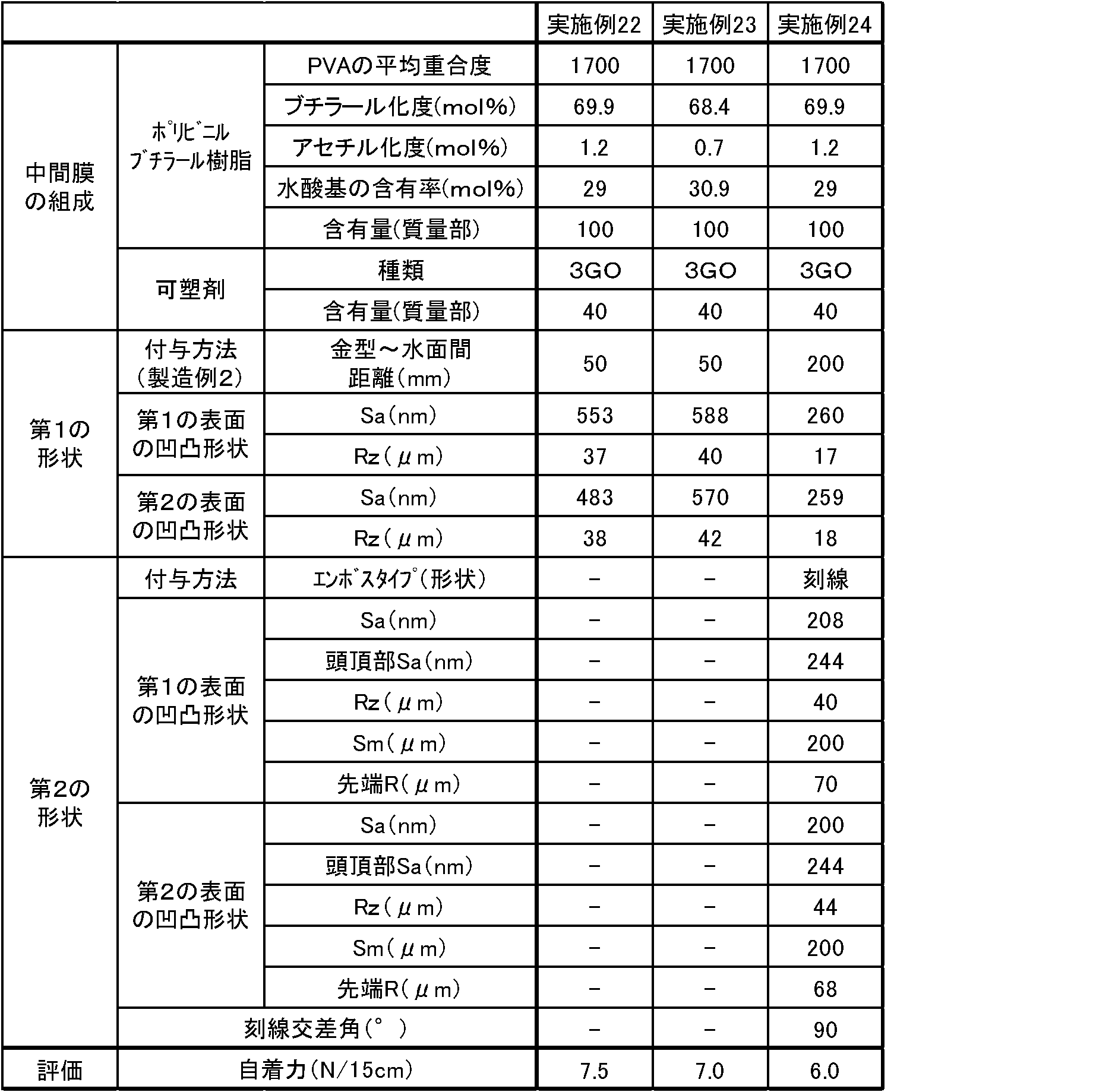
(保護層用樹脂組成物の調製)
平均重合度が1700のポリビニルアルコールをn-ブチルアルデヒドでアセタール化することにより得られたポリビニルブチラール(アセチル基量1モル%、ブチラール基量69モル%、水酸基量30モル%)100質量部に対して、可塑剤としてトリエチレングリコール-ジ-2-エチルヘキサノエート(3GO)36質量部を添加した。ミキシングロールで充分に混練し、保護層用樹脂組成物を得た。
平均重合度が3000のポリビニルアルコールをn-ブチルアルデヒドでアセタール化することにより得られたポリビニルブチラール(アセチル基量12.5モル%、ブチラール基量64.2モル%、水酸基量23.3モル%)100質量部に対して、可塑剤としてトリエチレングリコール-ジ-2-エチルヘキサノエート(3GO)76.5質量部を添加し、ミキシングロールで充分に混練し、中間層用樹脂組成物を得た。
得られた中間層用樹脂組成物と保護層用樹脂組成物を、共押出機を用いて共押出することにより、保護層用樹脂組成物からなる第1の保護層、中間層用樹脂組成物からなる中間層及び保護層用樹脂組成物からなる第2の保護層がこの順に積層された3層構造の合わせガラス用中間膜を得た。なお、凹凸付与後に得られる合わせガラス用中間膜において、第1の保護層及び第2の保護層の厚みがそれぞれ350μm、中間層の厚みが100μmとなるように押出条件を設定した。
その後、第1の形状の付与におけるエンボスロールの製造に用いるエンボスロール製造工程3で用いるブラスト剤の種類や、凹凸形状転写時のプレス圧を所期のRz値を得られるように調整した以外は実施例1と同様にして合わせガラス用中間膜に凹凸を付与し、その両面の凹凸の測定を行った。
第1の形状の付与におけるエンボスロールの製造に用いるエンボスロール製造工程3で用いるブラスト剤の種類や、凹凸形状転写時のプレス圧を所期のRz値を得られるように調整した以外は実施例25と同様にして合わせガラス用中間膜を製造し、その両面の凹凸の測定を行った。
第1の形状の付与におけるエンボスロールの製造に用いるエンボスロール製造工程3で用いるブラスト剤の種類や、凹凸形状転写時のプレス圧を所期のRz値を得られるように調整した以外は実施例25と同様にして合わせガラス用中間膜を製造し、第1の形状を付与した。
用いるポリビニルブチラールの組成を表6、表7に示す組成に変更し、第1の形状の付与におけるエンボスロールの製造に用いるエンボスロール製造工程3で用いる微細ブラスト剤の種類を表6、表7に示すように変更し、第2の形状の付与におけるエンボス形状及びピッチ巾を表6、表7に示すように変更し、さらに、所期の粗さが得られるように第2の形状の付与におけるプレス線圧を1~100kN/mの範囲で調節した以外は実施例27と同様にして合わせガラス用中間膜を製造し、その両面の凹凸の測定を行った。
実施例25~33、比較例7~9で得られた合わせガラス用中間膜について、実施例1と同様の方法により自着力の評価を行った。結果を表5~表7に示した。

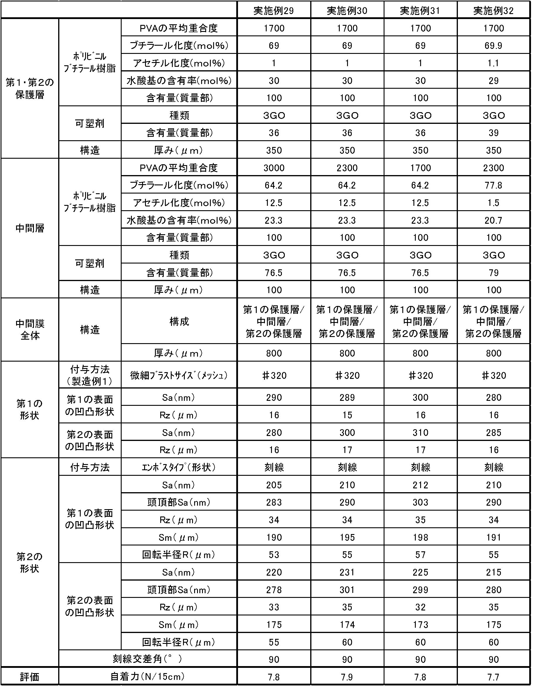

用いるポリビニルブチラールの組成を表8に示す組成に変更した以外は実施例25と同様にして、中間層用樹脂組成物及び保護層用樹脂組成物を得た。得られた中間層用樹脂組成物と保護層用樹脂組成物を、共押出機を用いて共押出することにより、保護層用樹脂組成物からなる第1の保護層、中間層用樹脂組成物からなる中間層及び保護層用樹脂組成物からなる第2の保護層がこの順に積層された3層構造の合わせガラス用中間膜を得た。その際、上記製造例2に従い、合わせガラス用中間膜を成膜すると同時に、第1の形状を付与した。
即ち、メルトフラクチャー現象を制御したエンボス付与法において、金型巾当たりの押し出し量を440kg/hr・m、金型から出た直後の膜表面温度を200℃、ダイ入り口の樹脂圧力を80kgf/cm2、膜を冷却する水槽内の水温を20℃~30℃の条件にて、合わせガラス用中間膜を成膜すると同時に、その両面に第1の形状を付与した。この際の金型から冷却水槽の表面までの距離を100mmとした。
得られた合わせガラス用中間膜の第1の保護層及び第2の保護層の厚みがそれぞれ350μm、中間層の厚みが100μmであった。また、実施例1と同様の方法によりSa値及びRz値を測定した。
第1の形状の付与における金型から冷却水槽の表面までの距離を表8に示したようにした以外は実施例34と同様にして合わせガラス用中間膜を製造し、その両面の凹凸の測定を行った。
実施例34~36、比較例10で得られた合わせガラス用中間膜について、実施例1と同様の方法により自着力の評価を行った。結果を表8に示した。

(合わせガラス用中間膜の作製及び第1の形状の付与)
実施例34と同様にして、合わせガラス用中間膜を成膜すると同時に、第1の形状を付与した。
第1の形状が付与された合わせガラス用中間膜の表面に、下記の手順により底部が連続した溝形状の凹凸を付与した。三角形斜線型ミルを用いて表面にミル加工を施した金属ロールと45~75のJIS硬度を有するゴムロールとからなる一対のロールを凹凸形状転写装置として用い、第1の形状が付与された合わせガラス用中間膜をこの凹凸形状転写装置に通し、合わせガラス用中間膜の第1の表面に底部が連続した溝形状である凹部が平行して等間隔に形成された凹凸を付与した。このときの転写条件として、合わせガラス用中間膜の温度を70℃、ロール温度を140℃、線速を10m/min、プレス線圧を1~100kN/mに調整した。次いで、合わせガラス用中間膜の第2の表面にも同様の操作を施し、底部が連続した溝形状の凹部を付与した。その際、第1の表面に付与した底部が連続した溝形状(刻線状)の凹部と、第2の表面に付与した底部が連続した溝形状(刻線状)の凹部との交差角度が20°となるようにした。第2の形状付与後に、実施例4と同様の方法により第1の表面及び第2の表面の凹凸を測定した。
用いるポリビニルブチラールの組成を表9に示す組成に変更し、第1の形状の付与における金型から冷却水槽の表面までの距離を表9に示すように変更し、第2の形状の付与におけるエンボス形状及びピッチ巾を表9に示したように変更し、更に、所期の粗さが得られるように第2の形状の付与におけるプレス線圧を1~100kN/mの範囲で調節した以外は実施例37と同様にして合わせガラス用中間膜を製造し、その両面の凹凸の測定を行った。
実施例37、38、比較例11で得られた合わせガラス用中間膜について、実施例1と同様の方法により自着力の評価を行った。結果を表9に示した。

2 任意に選択した一の凹部に隣接する凹部
3 任意に選択した一の凹部に隣接する凹部
A 凹部1と凹部2との間隔
B 凹部1と凹部3との間隔
10 合わせガラス用中間膜
11 第1の表面の底部が連続した溝形状の凹部
12 第2の表面の底部が連続した溝形状の凹部
20 第1の表面又は第2の表面の凹凸
21 底部が連続した溝形状の凹部
22 凸部
Claims (14)
- 少なくとも一方の表面に多数の凹部を有する合わせガラス用中間膜であって、
前記凹部を有する表面は、ISO 25178に準拠して測定される面算術平均粗さSaが200nm以上であることを特徴とする合わせガラス用中間膜。 - 凹部を有する表面は、ISO 25178に準拠して測定される面算術平均粗さSaが250nm以上であることを特徴とする請求項1記載の合わせガラス用中間膜。
- 凹部を有する表面は、多数の凹部が底部が連続した溝形状を有することを特徴とする請求項1又は2記載の合わせガラス用中間膜。
- 隣接する底部が連続した溝形状の凹部が平行して規則的に並列していることを特徴とする請求項3記載の合わせガラス用中間膜。
- 凹部を有する表面に、更に多数の凸部を有し、前記凸部の頭頂部のISO 25178に準拠して測定される面算術平均粗さSaが200nm以上であることを特徴とする請求項3又は4記載の合わせガラス用中間膜。
- 両面に多数の凹部を有する合わせガラス用中間膜であって、前記両面の凹部は底部が連続した溝形状を有し、一方の面に有する前記底部が連続した溝形状の凹部と、他方の面に有する前記底部が連続した溝形状の凹部との交差角θが10°以上であることを特徴とする請求項3、4又は5記載の合わせガラス用中間膜。
- 凹部を有する表面に、更に多数の凸部を有し、前記凸部の回転半径Rが200μm以下であることを特徴とする請求項3、4、5又は6記載の合わせガラス用中間膜。
- 凹部を有する表面は、JIS B 0601(1994)に準拠して測定される十点平均粗さRzが10μm以上であることを特徴とする請求項1、2、3、4、5、6又は7記載の合わせガラス用中間膜。
- 請求項1、2、3、4、5、6、7又は8記載の合わせガラス用中間膜が、一対のガラス板の間に積層されていることを特徴とする合わせガラス。
- 少なくとも一方の表面に多数の凹部と多数の凸部とを有する合わせガラス用中間膜であって、前記多数の凹部が底部が連続した溝形状を有し、前記凸部の頭頂部のISO 25178に準拠して測定される面算術平均粗さSaが200nm以上であることを特徴とする合わせガラス用中間膜。
- 請求項10記載の合わせガラス用中間膜が、一対のガラス板の間に積層されていることを特徴とする合わせガラス。
- 請求項1、2、3、4、5、6、7、8及び10記載の合わせガラス用中間膜の製造方法であって、
金属ロールに研削材を用いたブラスト処理により凹凸を形成するエンボスロール製造工程1と、前記凹凸を形成した金属ロールの凸部を一部研磨して平滑面を形成するエンボスロール製造工程2と、前記エンボスロール製造工程1で用いた研削材より微細な研削材を用いたブラスト処理により凹凸を形成するエンボスロール製造工程3との工程を有する製造工程によって作製されたエンボスロールを用いて、エンボスロール法により合わせガラス用中間膜の少なくとも一方の表面に多数の凹部を付与する工程を有することを特徴とする合わせガラス用中間膜の製造方法。 - エンボスロール製造工程3に用いる研削材のJIS R6001(1998)に準拠する累積高さ3%点の粒子径が150μm以下であり、かつ、JIS R6001(1998)に準拠する累積高さ94%点の粒子径が11μm以上であることを特徴とする請求項12記載の合わせガラス用中間膜の製造方法。
- 請求項1、2、3、4、5、6、7、8及び10記載の合わせガラス用中間膜の製造方法であって、
メルトフラクチャー現象を制御したエンボス付与法により合わせガラス用中間膜の少なくとも一方の表面に多数の凹部を付与するものであり、
合わせガラス用中間膜を形成するための樹脂組成物を金型から押出す工程と、押出された合わせガラス用中間膜を冷却水槽を用いて冷却する工程とを有し、前記冷却工程において前記金型から前記冷却水槽までの距離を250mm以下とする
ことを特徴とする合わせガラス用中間膜の製造方法。
Priority Applications (9)
| Application Number | Priority Date | Filing Date | Title |
|---|---|---|---|
| JP2016531731A JP6867160B2 (ja) | 2015-04-10 | 2016-04-08 | 合わせガラス用中間膜及び合わせガラス |
| KR1020177025049A KR102030915B1 (ko) | 2015-04-10 | 2016-04-08 | 합판 유리용 중간막, 합판 유리, 및, 합판 유리용 중간막의 제조 방법 |
| US15/551,631 US10850476B2 (en) | 2015-04-10 | 2016-04-08 | Interlayer for laminated glass, laminated glass, and production method for interlayer for laminated glass |
| CN202110304841.1A CN112876103B (zh) | 2015-04-10 | 2016-04-08 | 夹层玻璃用中间膜及夹层玻璃 |
| CN201680020126.2A CN107428609B (zh) | 2015-04-10 | 2016-04-08 | 夹层玻璃用中间膜的制造方法 |
| EP21160020.0A EP3851275A1 (en) | 2015-04-10 | 2016-04-08 | Interlayer for laminated glass, laminated glass, and production method for interlayer for laminated glass |
| MX2017012977A MX2017012977A (es) | 2015-04-10 | 2016-04-08 | Capa intermedia para vidrio laminado, vidrio laminado, y metodo de produccion para capa intermedia para vidrio laminado. |
| RU2017135236A RU2724662C2 (ru) | 2015-04-10 | 2016-04-08 | Промежуточный слой для многослойного стекла, многослойное стекло и способ изготовления промежуточного слоя для многослойного стекла |
| EP16776685.6A EP3281926B1 (en) | 2015-04-10 | 2016-04-08 | Interlayer for laminated glass, laminated glass, and production method for interlayer for laminated glass |
Applications Claiming Priority (2)
| Application Number | Priority Date | Filing Date | Title |
|---|---|---|---|
| JP2015-081179 | 2015-04-10 | ||
| JP2015081179 | 2015-04-10 |
Publications (1)
| Publication Number | Publication Date |
|---|---|
| WO2016163519A1 true WO2016163519A1 (ja) | 2016-10-13 |
Family
ID=57073258
Family Applications (1)
| Application Number | Title | Priority Date | Filing Date |
|---|---|---|---|
| PCT/JP2016/061548 WO2016163519A1 (ja) | 2015-04-10 | 2016-04-08 | 合わせガラス用中間膜、合わせガラス、及び、合わせガラス用中間膜の製造方法 |
Country Status (9)
| Country | Link |
|---|---|
| US (1) | US10850476B2 (ja) |
| EP (2) | EP3851275A1 (ja) |
| JP (2) | JP6867160B2 (ja) |
| KR (1) | KR102030915B1 (ja) |
| CN (2) | CN112876103B (ja) |
| MX (1) | MX2017012977A (ja) |
| RU (1) | RU2724662C2 (ja) |
| TW (1) | TWI712492B (ja) |
| WO (1) | WO2016163519A1 (ja) |
Cited By (2)
| Publication number | Priority date | Publication date | Assignee | Title |
|---|---|---|---|---|
| JPWO2016167287A1 (ja) * | 2015-04-15 | 2018-02-08 | 積水化学工業株式会社 | 合わせガラス用中間膜及び合わせガラス |
| CN109963824A (zh) * | 2017-03-31 | 2019-07-02 | 积水化学工业株式会社 | 夹层玻璃用中间膜、夹层玻璃用中间膜的制造方法和夹层玻璃 |
Families Citing this family (7)
| Publication number | Priority date | Publication date | Assignee | Title |
|---|---|---|---|---|
| RU2713024C2 (ru) | 2014-09-30 | 2020-02-03 | Секисуй Кемикал Ко., Лтд. | Промежуточная пленка для многослойного стекла и многослойное стекло |
| KR20190104024A (ko) * | 2016-12-29 | 2019-09-05 | 쌩-고벵 글래스 프랑스 | 헤드업 디스플레이(hud)용 pvb 필름, 그 형성 몰드 및 형성 방법 |
| WO2020067325A1 (ja) * | 2018-09-26 | 2020-04-02 | 積水化学工業株式会社 | 合わせガラス用中間膜及び合わせガラス |
| WO2021029620A1 (ko) | 2019-08-09 | 2021-02-18 | 에스케이씨 주식회사 | 접합용 필름 및 이를 포함하는 광투과 적층체 |
| KR102332194B1 (ko) * | 2020-02-27 | 2021-11-26 | 에스케이씨 주식회사 | 접합용 필름 및 이를 포함하는 광투과 적층체 |
| CN113880403B (zh) * | 2021-10-26 | 2023-06-30 | 常州亚玛顿股份有限公司 | 提高压花辊凹纹压延深度的压花装置、压花玻璃压延方法 |
| CN116277825A (zh) * | 2023-03-14 | 2023-06-23 | 中山博锐斯新材料股份有限公司 | 一种排气型夹胶玻璃用tpu薄膜生产方法 |
Citations (10)
| Publication number | Priority date | Publication date | Assignee | Title |
|---|---|---|---|---|
| JPS61154919A (ja) * | 1984-12-24 | 1986-07-14 | デイナミート・ノーベル・アクチエンゲゼルシヤフト | 低い表面粘着性を有するシートの製法 |
| JPH09508078A (ja) * | 1994-01-24 | 1997-08-19 | モンサント・カンパニー | 粗い表面を有する中間層 |
| JPH09295839A (ja) * | 1996-03-07 | 1997-11-18 | Sekisui Chem Co Ltd | 合わせガラス用中間膜 |
| JP2002154156A (ja) * | 2000-11-20 | 2002-05-28 | Sekisui Chem Co Ltd | エンボスロール及びその製造方法並びに合わせガラス用中間膜 |
| JP2003048762A (ja) * | 2001-08-01 | 2003-02-21 | Sekisui Chem Co Ltd | 合わせガラス用中間膜 |
| JP2003128442A (ja) * | 2001-04-18 | 2003-05-08 | Sekisui Chem Co Ltd | 合わせガラス用中間膜 |
| JP2003528749A (ja) * | 2000-03-29 | 2003-09-30 | イー・アイ・デュポン・ドウ・ヌムール・アンド・カンパニー | 方向性表面模様を有するガラス/ポリビニルブチラール積層体およびそれを調製する方法 |
| JP2011088783A (ja) * | 2009-10-22 | 2011-05-06 | Sekisui Chem Co Ltd | 合わせガラス用中間膜及び合わせガラス |
| JP2013010671A (ja) * | 2011-06-29 | 2013-01-17 | Sekisui Chem Co Ltd | 合わせガラス用中間膜及び合わせガラス |
| WO2015016366A1 (ja) * | 2013-08-01 | 2015-02-05 | 積水化学工業株式会社 | 合わせガラス用中間膜及び合わせガラス |
Family Cites Families (18)
| Publication number | Priority date | Publication date | Assignee | Title |
|---|---|---|---|---|
| JPH0826789A (ja) | 1994-07-22 | 1996-01-30 | Sekisui Chem Co Ltd | 合わせガラス用中間膜及びその製造装置並びにその製造方法 |
| US6093471A (en) * | 1999-02-08 | 2000-07-25 | Solutia Inc. | Polyvinyl butyral sheet |
| KR100665906B1 (ko) * | 1999-07-01 | 2007-01-09 | 세키스이가가쿠 고교가부시키가이샤 | 라미네이트된 글래스용 중간막 및 라미네이트된 글래스 |
| JP2001261385A (ja) * | 2000-01-13 | 2001-09-26 | Sekisui Chem Co Ltd | 合わせガラス用中間膜 |
| JP2002104846A (ja) * | 2000-07-27 | 2002-04-10 | Sekisui Chem Co Ltd | 合わせガラス用中間膜 |
| US20080254302A1 (en) | 2007-04-13 | 2008-10-16 | David Paul Bourcier | Multiple layer polymer interlayers having a melt fractured surface |
| RU68504U1 (ru) * | 2007-08-02 | 2007-11-27 | Общество с ограниченной ответственностью "НПО Протэкт" | Технологическая линия для получения сетчатого полимерного материала |
| US8609225B2 (en) * | 2009-05-21 | 2013-12-17 | Bridgestone Corporation | Ethylene-unsaturated ester copolymer film for forming laminate |
| FR2956924B1 (fr) | 2010-03-01 | 2012-03-23 | Saint Gobain | Cellule photovoltaique incorporant une nouvelle couche tco |
| JP2013141767A (ja) * | 2012-01-10 | 2013-07-22 | Mitsui Chemicals Tohcello Inc | エンボス加工シート、およびその製造方法 |
| TWI549816B (zh) | 2012-06-08 | 2016-09-21 | 長春石油化學股份有限公司 | 夾層玻璃用之中間膜及含其之夾層玻璃 |
| BR112015002011B1 (pt) | 2012-08-02 | 2021-06-08 | Sekisui Chemical Co., Ltd | filme de intercamadas para um vidro laminado |
| CN104918969A (zh) | 2012-12-17 | 2015-09-16 | 株式会社可乐丽 | 含橡胶接枝聚合物粉体、以及含有其的太阳能电池用密封材料及夹层玻璃用中间膜 |
| US9574028B2 (en) * | 2013-04-09 | 2017-02-21 | Solutia Inc. | Embossed polymer sheet |
| CA2916667A1 (en) * | 2013-08-01 | 2015-02-05 | Sekisui Chemical Co., Ltd. | Interlayer film for laminated glass and laminated glass |
| RU2693803C2 (ru) * | 2013-08-01 | 2019-07-04 | Секисуй Кемикал Ко., Лтд. | Лобовое стекло транспортного средства |
| CN105358503A (zh) * | 2013-08-01 | 2016-02-24 | 积水化学工业株式会社 | 夹层玻璃用中间膜以及夹层玻璃 |
| RU2719860C2 (ru) * | 2015-04-15 | 2020-04-23 | Секисуй Кемикал Ко., Лтд. | Промежуточная пленка для многослойного стекла и многослойное стекло |
-
2016
- 2016-04-08 US US15/551,631 patent/US10850476B2/en active Active
- 2016-04-08 TW TW105111160A patent/TWI712492B/zh active
- 2016-04-08 EP EP21160020.0A patent/EP3851275A1/en active Pending
- 2016-04-08 WO PCT/JP2016/061548 patent/WO2016163519A1/ja active Application Filing
- 2016-04-08 RU RU2017135236A patent/RU2724662C2/ru active
- 2016-04-08 EP EP16776685.6A patent/EP3281926B1/en active Active
- 2016-04-08 CN CN202110304841.1A patent/CN112876103B/zh active Active
- 2016-04-08 JP JP2016531731A patent/JP6867160B2/ja active Active
- 2016-04-08 CN CN201680020126.2A patent/CN107428609B/zh active Active
- 2016-04-08 MX MX2017012977A patent/MX2017012977A/es unknown
- 2016-04-08 KR KR1020177025049A patent/KR102030915B1/ko active IP Right Grant
-
2021
- 2021-03-31 JP JP2021060006A patent/JP7164657B2/ja active Active
Patent Citations (10)
| Publication number | Priority date | Publication date | Assignee | Title |
|---|---|---|---|---|
| JPS61154919A (ja) * | 1984-12-24 | 1986-07-14 | デイナミート・ノーベル・アクチエンゲゼルシヤフト | 低い表面粘着性を有するシートの製法 |
| JPH09508078A (ja) * | 1994-01-24 | 1997-08-19 | モンサント・カンパニー | 粗い表面を有する中間層 |
| JPH09295839A (ja) * | 1996-03-07 | 1997-11-18 | Sekisui Chem Co Ltd | 合わせガラス用中間膜 |
| JP2003528749A (ja) * | 2000-03-29 | 2003-09-30 | イー・アイ・デュポン・ドウ・ヌムール・アンド・カンパニー | 方向性表面模様を有するガラス/ポリビニルブチラール積層体およびそれを調製する方法 |
| JP2002154156A (ja) * | 2000-11-20 | 2002-05-28 | Sekisui Chem Co Ltd | エンボスロール及びその製造方法並びに合わせガラス用中間膜 |
| JP2003128442A (ja) * | 2001-04-18 | 2003-05-08 | Sekisui Chem Co Ltd | 合わせガラス用中間膜 |
| JP2003048762A (ja) * | 2001-08-01 | 2003-02-21 | Sekisui Chem Co Ltd | 合わせガラス用中間膜 |
| JP2011088783A (ja) * | 2009-10-22 | 2011-05-06 | Sekisui Chem Co Ltd | 合わせガラス用中間膜及び合わせガラス |
| JP2013010671A (ja) * | 2011-06-29 | 2013-01-17 | Sekisui Chem Co Ltd | 合わせガラス用中間膜及び合わせガラス |
| WO2015016366A1 (ja) * | 2013-08-01 | 2015-02-05 | 積水化学工業株式会社 | 合わせガラス用中間膜及び合わせガラス |
Non-Patent Citations (1)
| Title |
|---|
| See also references of EP3281926A4 * |
Cited By (7)
| Publication number | Priority date | Publication date | Assignee | Title |
|---|---|---|---|---|
| JPWO2016167287A1 (ja) * | 2015-04-15 | 2018-02-08 | 積水化学工業株式会社 | 合わせガラス用中間膜及び合わせガラス |
| CN109963824A (zh) * | 2017-03-31 | 2019-07-02 | 积水化学工业株式会社 | 夹层玻璃用中间膜、夹层玻璃用中间膜的制造方法和夹层玻璃 |
| JPWO2018181474A1 (ja) * | 2017-03-31 | 2020-02-06 | 積水化学工業株式会社 | 合わせガラス用中間膜、合わせガラス用中間膜の製造方法、及び、合わせガラス |
| EP3604253A4 (en) * | 2017-03-31 | 2021-01-06 | Sekisui Chemical Co., Ltd. | INTERMEDIATE LAYER FOR LAMINATED GLASS, PROCESS FOR THE PRODUCTION OF INTERMEDIATE LAYER FOR LAMINATED GLASS AND LAMINATED GLASS |
| CN109963824B (zh) * | 2017-03-31 | 2022-09-16 | 积水化学工业株式会社 | 夹层玻璃用中间膜、夹层玻璃用中间膜的制造方法和夹层玻璃 |
| JP7242301B2 (ja) | 2017-03-31 | 2023-03-20 | 積水化学工業株式会社 | 合わせガラス用中間膜、合わせガラス用中間膜の製造方法、及び、合わせガラス |
| US11613105B2 (en) | 2017-03-31 | 2023-03-28 | Sekisui Chemical Co., Ltd. | Interlayer for laminated glass, method for producing interlayer for laminated glass, and laminated glass |
Also Published As
| Publication number | Publication date |
|---|---|
| TWI712492B (zh) | 2020-12-11 |
| US20180022058A1 (en) | 2018-01-25 |
| CN107428609A (zh) | 2017-12-01 |
| EP3851275A1 (en) | 2021-07-21 |
| JP7164657B2 (ja) | 2022-11-01 |
| EP3281926B1 (en) | 2021-05-05 |
| RU2017135236A (ru) | 2019-04-09 |
| KR102030915B1 (ko) | 2019-10-10 |
| EP3281926A4 (en) | 2018-12-26 |
| CN112876103B (zh) | 2023-02-24 |
| US10850476B2 (en) | 2020-12-01 |
| JP2021104929A (ja) | 2021-07-26 |
| CN107428609B (zh) | 2021-05-14 |
| RU2724662C2 (ru) | 2020-06-25 |
| KR20170135829A (ko) | 2017-12-08 |
| CN112876103A (zh) | 2021-06-01 |
| JPWO2016163519A1 (ja) | 2018-02-01 |
| MX2017012977A (es) | 2018-02-01 |
| RU2017135236A3 (ja) | 2019-09-13 |
| TW201700292A (zh) | 2017-01-01 |
| JP6867160B2 (ja) | 2021-04-28 |
| EP3281926A1 (en) | 2018-02-14 |
Similar Documents
| Publication | Publication Date | Title |
|---|---|---|
| JP7164657B2 (ja) | 合わせガラス用中間膜の製造方法 | |
| JP7101237B2 (ja) | 合わせガラス用中間膜、合わせガラス、エンボスロールの製造方法及び合わせガラス用中間膜の製造方法 | |
| WO2015156365A1 (ja) | 自動車用フロントガラス用中間膜、ロール状体及び自動車用フロントガラス | |
| JPWO2016056668A1 (ja) | 合わせガラス用中間膜及び合わせガラス | |
| JP2020050585A (ja) | 合わせガラス用中間膜及び合わせガラス | |
| WO2016167287A1 (ja) | 合わせガラス用中間膜及び合わせガラス | |
| WO2017171032A1 (ja) | 合わせガラス用中間膜及び合わせガラス | |
| JP2017178677A (ja) | 合わせガラス用中間膜及び合わせガラス | |
| JP2017178679A (ja) | 合わせガラス用中間膜及び合わせガラス |
Legal Events
| Date | Code | Title | Description |
|---|---|---|---|
| ENP | Entry into the national phase |
Ref document number: 2016531731 Country of ref document: JP Kind code of ref document: A |
|
| 121 | Ep: the epo has been informed by wipo that ep was designated in this application |
Ref document number: 16776685 Country of ref document: EP Kind code of ref document: A1 |
|
| WWE | Wipo information: entry into national phase |
Ref document number: 15551631 Country of ref document: US |
|
| ENP | Entry into the national phase |
Ref document number: 20177025049 Country of ref document: KR Kind code of ref document: A |
|
| WWE | Wipo information: entry into national phase |
Ref document number: 2017135236 Country of ref document: RU |
|
| WWE | Wipo information: entry into national phase |
Ref document number: MX/A/2017/012977 Country of ref document: MX |
|
| NENP | Non-entry into the national phase |
Ref country code: DE |