WO2016163459A1 - 電動機装置 - Google Patents
電動機装置 Download PDFInfo
- Publication number
- WO2016163459A1 WO2016163459A1 PCT/JP2016/061401 JP2016061401W WO2016163459A1 WO 2016163459 A1 WO2016163459 A1 WO 2016163459A1 JP 2016061401 W JP2016061401 W JP 2016061401W WO 2016163459 A1 WO2016163459 A1 WO 2016163459A1
- Authority
- WO
- WIPO (PCT)
- Prior art keywords
- electric motor
- phase
- mode
- motor device
- internal combustion
- Prior art date
- Legal status (The legal status is an assumption and is not a legal conclusion. Google has not performed a legal analysis and makes no representation as to the accuracy of the status listed.)
- Ceased
Links
Images


Classifications
-
- B—PERFORMING OPERATIONS; TRANSPORTING
- B60—VEHICLES IN GENERAL
- B60W—CONJOINT CONTROL OF VEHICLE SUB-UNITS OF DIFFERENT TYPE OR DIFFERENT FUNCTION; CONTROL SYSTEMS SPECIALLY ADAPTED FOR HYBRID VEHICLES; ROAD VEHICLE DRIVE CONTROL SYSTEMS FOR PURPOSES NOT RELATED TO THE CONTROL OF A PARTICULAR SUB-UNIT
- B60W10/00—Conjoint control of vehicle sub-units of different type or different function
- B60W10/04—Conjoint control of vehicle sub-units of different type or different function including control of propulsion units
- B60W10/08—Conjoint control of vehicle sub-units of different type or different function including control of propulsion units including control of electric propulsion units, e.g. motors or generators
-
- B—PERFORMING OPERATIONS; TRANSPORTING
- B60—VEHICLES IN GENERAL
- B60W—CONJOINT CONTROL OF VEHICLE SUB-UNITS OF DIFFERENT TYPE OR DIFFERENT FUNCTION; CONTROL SYSTEMS SPECIALLY ADAPTED FOR HYBRID VEHICLES; ROAD VEHICLE DRIVE CONTROL SYSTEMS FOR PURPOSES NOT RELATED TO THE CONTROL OF A PARTICULAR SUB-UNIT
- B60W20/00—Control systems specially adapted for hybrid vehicles
-
- F—MECHANICAL ENGINEERING; LIGHTING; HEATING; WEAPONS; BLASTING
- F02—COMBUSTION ENGINES; HOT-GAS OR COMBUSTION-PRODUCT ENGINE PLANTS
- F02N—STARTING OF COMBUSTION ENGINES; STARTING AIDS FOR SUCH ENGINES, NOT OTHERWISE PROVIDED FOR
- F02N11/00—Starting of engines by means of electric motors
- F02N11/04—Starting of engines by means of electric motors the motors being associated with current generators
-
- F—MECHANICAL ENGINEERING; LIGHTING; HEATING; WEAPONS; BLASTING
- F02—COMBUSTION ENGINES; HOT-GAS OR COMBUSTION-PRODUCT ENGINE PLANTS
- F02N—STARTING OF COMBUSTION ENGINES; STARTING AIDS FOR SUCH ENGINES, NOT OTHERWISE PROVIDED FOR
- F02N11/00—Starting of engines by means of electric motors
- F02N11/08—Circuits specially adapted for starting of engines
-
- H—ELECTRICITY
- H02—GENERATION; CONVERSION OR DISTRIBUTION OF ELECTRIC POWER
- H02P—CONTROL OR REGULATION OF ELECTRIC MOTORS, ELECTRIC GENERATORS OR DYNAMO-ELECTRIC CONVERTERS; CONTROLLING TRANSFORMERS, REACTORS OR CHOKE COILS
- H02P27/00—Arrangements or methods for the control of AC motors characterised by the kind of supply voltage
- H02P27/04—Arrangements or methods for the control of AC motors characterised by the kind of supply voltage using variable-frequency supply voltage, e.g. inverter or converter supply voltage
- H02P27/06—Arrangements or methods for the control of AC motors characterised by the kind of supply voltage using variable-frequency supply voltage, e.g. inverter or converter supply voltage using DC to AC converters or inverters
-
- Y—GENERAL TAGGING OF NEW TECHNOLOGICAL DEVELOPMENTS; GENERAL TAGGING OF CROSS-SECTIONAL TECHNOLOGIES SPANNING OVER SEVERAL SECTIONS OF THE IPC; TECHNICAL SUBJECTS COVERED BY FORMER USPC CROSS-REFERENCE ART COLLECTIONS [XRACs] AND DIGESTS
- Y02—TECHNOLOGIES OR APPLICATIONS FOR MITIGATION OR ADAPTATION AGAINST CLIMATE CHANGE
- Y02T—CLIMATE CHANGE MITIGATION TECHNOLOGIES RELATED TO TRANSPORTATION
- Y02T10/00—Road transport of goods or passengers
- Y02T10/10—Internal combustion engine [ICE] based vehicles
- Y02T10/40—Engine management systems
Definitions
- the present disclosure relates to a vehicle electric motor device that assists the output of an internal combustion engine such as a vehicle engine.
- Patent Document 1 discloses an electric motor device including a plurality of three-phase bridge circuits as switching means for turning on and off energization of windings of each phase of a rotating electrical machine.
- the semiconductor switch which a some 3 phase bridge circuit has is comprised by 1 chip
- tip MOSFET tip MOSFET
- Patent Documents 2 to 5 do not directly describe the achievement of cost reduction and downsizing of the electric motor device, but the outline is abbreviated.
- the number of turns energized by power supply from the battery (hereinafter referred to as the actual number of turns) is set in order to enable optimal control according to the load to be driven of the electric motor device. It can be changed for each phase by relay switch. As a result, for example, when low-speed and high-torque output is required, the number of actual turns per phase is increased, and when high-speed and low-torque output is required, the number of actual turns per phase is decreased, resulting in low to high rotation. It is said that it is possible to improve the workability by generating torque.
- Patent Document 4 discloses a configuration in which the maximum torque of the starter motor, which is a rotating electrical machine, is set to 60% or less of the “compressed maximum cranking torque” in the engine starter. With this configuration, drivability can be improved by reducing the inertial mass. Furthermore, Patent Document 5 states that, in an electric motor device including a wound field type rotating electrical machine, safety can be improved by making the limit value of the field current variable according to the rotational speed.
- An object of the present disclosure is to promote cost reduction and downsizing in an electric motor device for a vehicle.
- the electric motor device includes a rotating electric machine having a three-phase winding, a switch for turning on and off the application of voltage to the winding, and giving an instruction to the switch to operate the rotating electric machine.
- the electric motor device is for a vehicle, and based on control by the control means, power is supplied from a battery to operate the rotating electric machine as an electric motor, and assists the output of the internal combustion engine by the output generated by the operation as the electric motor.
- the electric motor device includes a rotation speed detection means for detecting the rotation speed of the internal combustion engine
- the control means has the following two-phase mode and three-phase mode. That is, in the three-phase mode, the first combination (W, U), the second combination (the combination of the windings that become the high potential side when the battery voltage is applied to the three-phase windings (U to W) ( U, V) and the third combination (V, W) are sequentially repeated.
- the two-phase mode is a mode in which at least one combination is not executed among the first combination (W, U), the second combination (U, V), and the third combination (V, W).
- the control means has a first threshold for the rotational speed of the internal combustion engine, and uses the two-phase mode when the value detected by the rotational speed detection means is larger than the first threshold.
- the two-phase mode it is possible to reduce the power consumption necessary for operating the rotating electrical machine as an electric motor, and to suppress heat generation by distributing the energization to the switches and windings. . Further, even if the rotational driving force of the rotating electrical machine decreases due to the use of the two-phase mode, the reverse rotation and the stop can be prevented by using the rotation of the rotating electrical machine by the internal combustion engine. For this reason, cost reduction and size reduction can be promoted in the electric motor apparatus for vehicles.
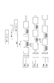
- FIG. 1 is an overall configuration diagram illustrating an electric motor device according to a first embodiment.
- FIG. 2A is a transition diagram showing transition of on / off of the switch in the large mode operation of the first embodiment;
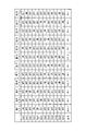
- FIG. 2B is a table showing an example of combinations of switches that are turned on and off in the operation of the inverter of the first embodiment.
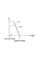
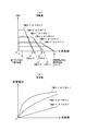
- FIG. 3 shows the correlation between the rotational speed and torque when the rotating electrical machine of the first embodiment is operated as an electric motor.
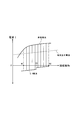
- FIG. 4 is a characteristic diagram showing an operation example of the electric motor apparatus according to the first embodiment.
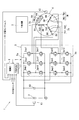
- FIG. 5 is an overall configuration diagram showing the electric motor device of the second embodiment, FIG.
- FIG. 6 is a table showing combinations of switches that are turned on and off in the operation of the inverter of the second embodiment.
- FIG. 7A is a diagram showing the correlation between the rotational speed and the torque when the rotating electrical machine of the second embodiment is operated as an electric motor
- FIG. 7B is the rotation of the second embodiment. It is a diagram showing the correlation between the rotational speed and the generated current when the electric machine is operated as a generator
- FIG. 8 is an overall configuration diagram showing the electric motor device of the third embodiment
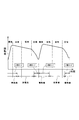
- FIG. 9 is a time chart showing the switching transition of the electric motor and the generator according to the stroke of the internal combustion engine of the third embodiment
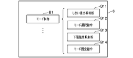
- FIG. 10 is a block diagram for explaining a part of the function of the control unit in the first embodiment.
- FIG. 11 is a block diagram for explaining a part of the function of the control unit in the second embodiment.
- FIG. 12 is a block diagram for explaining a part of the function of the control unit in the third embodiment.
- An electric motor device (hereinafter referred to as a system) 1 is provided in a vehicle and generates an output by feeding power from an in-vehicle battery (hereinafter simply referred to as a battery 2) to start the internal combustion engine 3. It assists the output of the internal combustion engine 3 or charges the battery 2 with a voltage induced by the driving force of the internal combustion engine 3, and has both functions of an electric motor and a generator.
- the system 1 is provided with the following rotary electric machines 4, the inverter 5, and the control part (functioning as a control means) 6.
- the rotating electrical machine 4 operates as an electric motor that starts the internal combustion engine 3 or assists the output of the internal combustion engine 3 or a generator that charges the battery 2.
- U-phase, V-phase, and W-phase windings 7U, 7V, and 7W are star-connected to a stator, and a permanent magnet is built into the rotor.
- the rotor of the rotating electrical machine 4 is directly connected to the crankshaft of the internal combustion engine 3.
- the rotating electrical machine 4 is provided with a position sensor 4a for detecting the magnet position of the rotor.
- the position sensor 4a includes three hall sensors PU, PV, and PW arranged at the stator pole intervals. Become.
- the inverter 5 is a three-phase bridge circuit in which two semiconductor switches are connected in series and three series connections of two semiconductor switches are connected in parallel (hereinafter, the semiconductor switch is referred to as a switch S). ).
- the semiconductor switch is referred to as a switch S.
- one terminal connected in series is connected to the positive electrode of the battery 2, and the other terminal is connected to the ground. Further, the three midpoints of the series connection are connected to the U terminal 9U, the V terminal 9V, and the W terminal 9W, respectively.
- a smoothing capacitor 10 is connected to the inverter 5 in parallel.
- the switch S is, for example, an N channel type power MOSFET.
- the high potential side switch S and the low potential side switch S are respectively referred to as switches Sup and Sun.
- the high potential side switch S and the low potential side switch S may be referred to as switches Svp and Svn, respectively.
- the high potential side switch S and the low potential side switch S may be referred to as switches Swp and Swn, respectively.
- control unit (control means) 6 is an electronic control unit (ECU) that controls the operation of the rotating electrical machine 4.
- the control unit 6 includes, for example, an input circuit 6A that processes an input signal, a CPU 6B (Central Processing Unit) that performs control processing and arithmetic processing based on the input signal, and is necessary for control processing and arithmetic processing.
- Various memories 6C that store and hold data, programs, and the like, an output circuit 6D that outputs necessary signals based on the processing results of the CPU 6A, and the like.
- control unit 6 selects one of the six switches S of the inverter 5 that is sequentially turned on and off, and the switch that is to be sequentially turned on and off in order to control the operation of the rotating electrical machine 4. Change S.
- control part 6 has the following 3 phase mode and 2 phase mode as a control mode which operates the rotary electric machine 4 as an electric motor (refer FIG. 2B).
- FIG. 2A shows the on / off transition of the switch S in the operation as an electric motor, with the rotational speed Ne of the internal combustion engine 3 as the horizontal axis
- FIG. 2B shows the three-phase and two-phase modes, respectively.
- 1 shows an example of a combination of the six switches S that are turned on and off.
- the three-phase mode is a well-known three-phase motor drive mode in which a voltage is applied to the windings 7U to 7W, and the winding that becomes the high potential side when the voltage of the battery 2 is applied to the windings 7U to 7W.
- the following first to third combinations are repeated as combinations of 7U to 7W.
- the first combination is a combination in which the windings 7W and 7U are on the high potential side, and is realized by the first pattern of FIG. 2B.
- the second combination is a combination in which the windings 7U and 7V have a high potential, and is realized by the second pattern in FIG. 2B.
- the third combination is a combination in which the windings 7V and 7W have a high potential, and is realized by the third pattern in FIG. 2B.
- the two-phase mode is a mode in which at least one of the first to third combinations is not executed.
- FIG. 2B illustrates four modes (shown as two-phase modes 1 to 4) in which none of the first to third combinations is executed as the two-phase mode.
- the two-phase mode 1 by repeating the fourth, fifth and twentieth patterns, only the winding 7U is on the high potential side, and a voltage is applied to the windings 7U and 7V. Only a state where a voltage is applied to the windings 7V and 7W and a state where no voltage is applied to any of the windings 7U to 7W is repeated.
- the system 1 includes a rotation speed detector 12 (functioning as a rotation speed detection means) that detects the rotation speed of the internal combustion engine 3.
- the control unit 6 has a first threshold value C0 set in advance in the memory 6C with respect to the rotational speed of the internal combustion engine 3.
- the CPU 6B reads a control program stored in advance in the memory 6C and executes it as a given main routine or subroutine based on the first threshold value C0 and the value detected by the rotation speed detector 12.
- the first threshold value C0> the lowest frequency that can be driven by the internal combustion engine 3 is set.
- the control unit 6 controls the drive of the inverter 5 through the execution of the control program by the CPU 6B, and exhibits the mode control function B1 schematically shown in FIG.
- the control unit 6 uses the mode control function B1 to determine whether the value detected by the rotation speed detector 12 is greater than the first threshold value C0 and equal to or less than the limit rotation speed (threshold comparison determination B11).
- the limit rotational speed refers to a limit rotational speed that can be rotationally driven as an electric motor.
- the control unit 6 uses the same function B1 to select either the three-phase mode or the two-phase mode when the value detected by the rotation speed detector 12 is larger than the first threshold value C0 and equal to or less than the limit rotation speed. (Mode selection command B12).
- the rotational speed detector 12 is a crank angle sensor having a known structure that detects the crank angle of the internal combustion engine 3, for example. In other words, the rotational speed detector 12 detects the crank angle with a protrusion provided on the outer periphery of the crankshaft, and is used for ignition control and fuel injection control of the internal combustion engine 3.
- the correlation between the rotational speed and the torque when using the two-phase mode is lower than that when using the three-phase mode and is slightly faster.
- the control unit 6 determines whether or not the detected rotational speed is equal to or lower than the lower limit value using the mode control function B1 (lower limit value comparison determination B13). Is fixed to the three-phase mode (mode fixing command B14).
- the 2-phase mode 1, the 2-phase mode 2, and the 2-phase mode 3 may be sequentially switched. That is, the two-phase mode 1 ⁇ the two-phase mode 2 ⁇ the two-phase mode 3 may be sequentially repeated.
- energization to the windings 7U to 7W and the switch S can be dispersed, and heat generation can be suppressed. For this reason, since the emitted-heat amount concerned when the rotation speed of the internal combustion engine 3 is high can be reduced, size reduction and cost reduction of an apparatus can be achieved.
- control unit 6 controls the charging of the battery 2 by the parasitic diode associated with the semiconductor switch S that is not selected to be turned on by the operation on the inverter 5.
- the switches S selected to be turned on are the switches Sup and Svn, and the windings 7U and 7V are supplied with power from the battery 2.
- the voltage induced in the winding 7W can charge the battery 2 while being regulated by a parasitic diode associated with the switch Swp by turning the switch Swn on and off (for example, FIG. 2A). (See the circled inside.)
- FIG. 4 exemplifies operating characteristics when the rotational speed of the internal combustion engine 3 changes between N1 and N2.
- the horizontal axis represents the rotational speed Ne of the internal combustion engine 3
- the vertical axis represents the current I flowing between the battery 2 and the inverter 5, and the direction of flow when operating as a generator is positive.
- the currents flowing as the generator and the motor are called the generated current and the motor current, respectively, and are indicated by solid lines.
- a current flowing through another electric load is called an electric load current and indicated by a dotted line.
- the generated current is controlled to be larger than the electric load current.
- the three-phase mode or the two-phase mode is selected in the range of the rotational speed of the internal combustion engine 3 that is smaller than the first threshold value C0 and equal to or higher than the lower limit value.
- the rotational speed of the internal combustion engine 3 is larger than the first threshold value C0
- the three-phase mode or the two-phase mode is selected in the same manner when the rotational speed is equal to or lower than the limit rotational speed.
- the three-phase mode is fixedly selected.
- the rotational speed Ne and the current I travel between the solid line of the generated current and the solid line of the motor current in accordance with the rotational speed of the internal combustion engine 3 and the charge balance of the battery 2. .
- the control unit 6 has a three-phase mode and a two-phase mode, and the two-phase mode when the value detected by the rotation speed detector 12 is larger than the first threshold value C0.
- Use mode As a result, by using the two-phase mode, it is possible to reduce the power consumption required to operate the rotating electrical machine 4 as an electric motor, and partially omit the energization of the switch S and the windings 7U to 7W. By doing so, heat generation can be suppressed.
- the control unit 6 controls charging of the battery 2 by a parasitic diode associated with the semiconductor switch S that is not selected to be turned on by the inverter operation. Thereby, charging efficiency can be improved.
- the system 1 of the second embodiment is used.
- the description will focus on the configuration different from that of the system 1 of the first embodiment, and the same configurations as those described in the first embodiment are denoted by the same reference numerals, and the description thereof is omitted. Simplify.
- the system 1 of the second embodiment as shown in FIG. 5, by providing intermediate taps 8U, 8V, and 8W on the windings 7U to 7W, the actual number of turns can be made variable for each phase.
- the actual number of turns refers to the number of turns in each of the windings 7U to 7W that is energized by power supply from the battery 2 in the operation as an electric motor, or the induced voltage in the operation as a generator. This is the number of turns of the part to be supplied. For this reason, in the windings 7U to 7W of the rotating electrical machine 4, the resistance value of a portion that is energized by power supply from the battery 2 in the operation as an electric motor or a portion that supplies an induced voltage to the battery 2 in the operation as a generator. Is variable.
- winding 7U two windings 7U1 and 7U2 are connected in series, and an intermediate tap 8U is provided at a connection portion between the windings 7U1 and 7U2.
- winding 7V two windings 7V1 and 7V2 are connected in series, and an intermediate tap 8V is provided at a connection portion between the winding 7V1 and the winding 7V2.
- winding 7W two windings 7W1 and 7W2 are connected in series, and an intermediate tap 8W is provided at a connection portion between the winding 7W1 and the winding 7W2.
- the windings 7U1, 7U2, 7V1, 7V2, 7W1, and 7W2 all have the same number of turns, and the terminals that do not form the intermediate taps 8U, 8V, and 8W in the windings 7U2, 7V2, and 7W2, respectively. Connected.
- terminals on which the intermediate taps 8U, 8V, and 8W are not formed in the windings 7U1, 7V1, and 7W1 are referred to as a U terminal 9U, a V terminal 9V, and a W terminal 9W, respectively.
- the number of turns of the windings 7U1, 7U2, 7V1, 7V2, 7W1, and 7W2 are all set to the same integer n for the sake of simplicity.
- the system 1 of the second embodiment includes two inverters 5.
- the inverters 5 are both three-phase bridge circuits in which two switches S are connected in series and three series connections of two semiconductor switches S are connected in parallel.
- one terminal connected in series is connected to the positive electrode of the battery 2, and the other terminal is connected to the ground. Further, the three midpoints of the series connection are connected to the U terminal 9U, the V terminal 9V, and the W terminal 9W, respectively.
- one terminal connected in series is connected to the positive electrode of the battery 2, and the other terminal is connected to the ground. Further, the three midpoints of the series connection are respectively connected to the intermediate taps 8U, 8V, and 8W (hereinafter, the inverter 5 connected to the U terminal 9U, the V terminal 9V, and the W terminal 9W is referred to as an inverter 5a.
- the inverter 5 connected to 8U, 8V, and 8W may be called the inverter 5b.).
- the semiconductor switch S is, for example, an N channel type power MOSFET.
- the high potential side switch S and the low potential side switch S are respectively referred to as switches Sup1, Sun1.
- switches Svp1 and Svn1 are respectively referred to as switches Svp1 and Svn1, respectively.
- the high potential side switch S and the low potential side switch S may be referred to as switches Swp1 and Swn1, respectively.
- the high-potential side and low-potential side switches S are referred to as switches Sup2 and Sun2, respectively.
- switches Sup2 and Sun2 are referred to as switches Sup2 and Sun2, respectively.
- switches Svp2 and Svn2 are referred to as switches Svp2 and Svn2, respectively.
- switches Swp2 and Swn2 are referred to as switches Swp2 and Swn2, respectively.
- the control unit 6 selects one of the 12 switches S included in the inverters 5a and 5b that is sequentially turned on and off, and the switch that should be selected sequentially. S is changed (hereinafter, one of the twelve switches S that is sequentially turned on / off is selected, and the operation that sequentially changes the switch S to be selected may be referred to as an inverter operation).
- control part 6 changes the number of real turns for every phase by performing inverter operation. More specifically, the control unit 6 selects from three numerical values of 2n, 3n, and 4n regarding the actual number of turns in all phases in the inverter operation. For example, when power is supplied to the windings 7U and 7V in the operation as an electric motor, if the switches Sup1 and Svn1 are selected to be turned on, the windings 7U1, 7U2, 7V1 and 7V2 are supplied with power from the battery 2, The actual number of turns for each V phase is 2n and 2n, and the actual number of turns for all phases is 4n.
- the windings 7U2 and 7V2 are supplied with power from the battery 2, so that the actual turn numbers of the U phase and the V phase are n and n, respectively, The number is 2n.
- the windings 7U1, 7U2 and 7V2 are supplied with power from the battery 2, so that the actual number of turns in the U phase and V phase is 2n and n, respectively.
- the actual number of turns is 3n.
- the windings 7U2, 7V1 and 7V2 are supplied with power from the battery 2, so that the actual number of turns of the U phase and the V phase is n and 2n, respectively.
- the actual number of turns is 3n.
- the inverter operation the actual number of turns in all phases when voltage is applied from the battery 2 to the two phases of the three-phase windings 7U to 7W or the induced voltage is supplied to the battery 2 from the two phases.
- the modes for selecting 4n, 2n, and 3n are referred to as a large mode, a small mode, and a medium mode, respectively, from the viewpoint of the magnitude of drive energy.
- the system 1 there are three-phase and two-phase mode divisions and large, small and medium mode divisions. That is, in the system 1, as an inverter operation option, three-phase mode and large mode, three-phase mode and small mode, three-phase mode and medium mode, two-phase mode and large mode, two-phase mode and small mode, and two-phase mode There are six modes of the medium mode.
- FIG. 6 shows combinations of the 12 switches S that are turned on and off in each of the three-phase mode and large mode, the three-phase mode and small mode, the three-phase mode and medium mode. That is, in the three-phase mode and the large mode and the three-phase mode and the small mode, the seventh to ninth patterns and the tenth to twelfth patterns are sequentially repeated, respectively. In the three-phase mode and the medium mode, the thirteenth to fifteenth patterns or the sixteenth to eighteenth patterns are sequentially repeated.
- the two-phase mode and large mode, the two-phase mode and small mode, and the two-phase mode and medium mode are the same as the two-phase modes 1 to 4 in the first embodiment, and will not be described.
- the correlation between the rotational speed and the torque when the rotating electrical machine 4 is operated as an electric motor, and the correlation between the rotational speed and the generated current when the rotating electrical machine 4 is operated as a generator are three-phase mode and large.
- FIG. 7 shows, for example, each of the mode, the three-phase mode and the medium mode, the three-phase mode and the small mode.
- the correlations of the two-phase mode and the large mode, the two-phase mode and the medium mode, the two-phase mode and the small mode are also shown.
- the large mode when operating as an electric motor, the large mode is suitable for assisting when the rotational speed of the internal combustion engine 3 is in the middle speed range from the low rotational speed, and the medium mode is the rotational speed of the internal combustion engine 3.
- the low mode is suitable for assisting when the rotational speed of the internal combustion engine 3 is in a high rotational speed region near 5000 rpm.
- the large mode in the operation as a generator, the large mode has a large number of actual turns, so that the induced voltage becomes high and can be charged even when the rotational speed of the internal combustion engine 3 is low.
- the internal combustion engine 3 can be charged at a medium speed or higher, and in the small mode, the internal combustion engine 3 can be charged at a high speed or higher.
- the system 1 of the second embodiment includes a voltage detector 15 (functioning as a voltage detection means) that detects the voltage of the battery 2.
- the voltage detector 15 is provided as an A / D conversion circuit having a known structure, for example.
- control unit 6 executes the inverter operation by selecting one of the large, small, and medium modes according to the detection values of the rotation speed detector 12 and the voltage detector 15, and the rotating electric machine 4 is driven by the electric motor. Or operate as a generator.
- control unit 6 rotates based on the charge balance of the battery 2 predicted using the change over time of the detection value by the voltage detector 15 or the detection value by the voltage detector 15 when starting the internal combustion engine 3. It is determined whether or not the electric machine 4 is operated as an electric motor.
- the control unit 6 2 when the estimated charge balance of the battery 2 is negative, or when the detected value of the voltage of the battery 2 when starting the internal combustion engine 3 is lower than the reference value, the control unit 6 2 is regarded as having a high necessity of charging, and the rotating electrical machine 4 is controlled to operate as a generator, and the rotating electrical machine 4 is not operated as an electric motor. That is, the control unit 6 selects the actual number of turns so that the voltage induced in the windings 7U to 7W is higher than the voltage of the battery 2, and operates as a generator.
- the control unit 6 has second threshold values C1 and C2 (C1 ⁇ C2) set in advance for the rotational speed of the internal combustion engine 3 for each phase.
- the relationship between the rotation speed and the threshold is “Lower limit rotation speed (lower limit value) that can be rotated ⁇ first threshold value C0 ⁇ Second threshold C1 for three-phase mode ⁇ second C2 for two-phase mode ⁇ It is in the relationship of the limit rotation speed which can be rotated in a small mode (3 phase mode and 2 phase mode).
- the control unit 6 When operating the rotating electrical machine 4 as an electric motor, the control unit 6 changes the actual number of turns for each phase according to the result of comparison between the detected value by the rotational speed detector 12 and the threshold values C1 and C2. Specifically, the control unit 6 obtains a mode selection function B2 as schematically shown in FIG. 11 by executing a control program of the CPU 6B. For this reason, the mode selection function B2 makes a comparison judgment between the detection value by the rotation speed detector 12 and the lower limit rotation speed, one second threshold value C1, the other second threshold value C2, and the limit rotation speed ( Threshold comparison judgment B21).
- control unit 6 selects the inverters 5a and 5b from the combinations of the three-phase / two-phase mode and the large / medium / small mode for each rotation speed range based on the threshold comparison judgment through the mode selection function B2. Are selectively commanded (mode selection command B22).
- the drive mode is selected from a total of three types of modes: a large mode of the three-phase mode, a medium mode, and a small mode
- a large mode of the three-phase mode When it is determined that the detected rotational speed is within the range of the lower limit rotational speed or more and less than one second threshold C1, a total of 6 large modes, medium modes, and small modes in each of the three-phase mode and the two-phase mode 6
- the drive mode is selected from the types of modes, When it is determined that the detected rotational speed falls within the range of one second threshold C1 or more and less than the other second threshold C2, a total of 4 medium modes and small modes of the three-phase mode and the two-phase mode, respectively.
- the drive mode is selected from the types of modes, ⁇
- the three-phase mode and the small mode of each of the two-phase modes A mode is selected.
- Arbitrary mode is employ
- the control unit 6 when the detection value by the rotational speed detector 12 is larger than one second threshold value C1 and smaller than the other second threshold value C2, the control unit 6 has a three-phase mode and a two-phase mode, respectively.
- the middle mode or the small mode is adopted to operate the rotating electric machine 4 as an electric motor.
- the internal combustion engine 3 is assisted with an arbitrary output of medium-speed medium torque or medium-speed small torque.
- the control unit 6 employs the three-phase mode or the small mode of the two-phase mode to operate the rotating electrical machine 4 as an electric motor when the value detected by the rotation speed detector 12 is larger than the other second threshold value C2. .
- the internal combustion engine 3 assists with an arbitrary output during high speed or high speed and low torque.
- the rotating electrical machine 4 makes the actual number of turns variable for each phase by providing the intermediate taps 14 in the windings 7U to 7W of each phase.
- the control unit 6 selects one of the switches S included in the two inverters 5a and 5b that is sequentially turned on and off, and executes an inverter operation that sequentially changes the switch S to be selected, thereby rotating the control unit 6
- the operation of the electric machine 4 is controlled.
- the control part 6 changes the number of real turns for every phase by performing inverter operation.
- FIG. 11 shows functions provided when the CPU 6B reads and executes the control program according to the second embodiment of the memory 6C, that is, the functional blocks of the control unit 6.
- the number of actual turns can be increased or decreased at high speed for each phase, so that the output of the motor or generator can be changed at high speed, or the operation of the rotating electrical machine 4 can be switched between the motor and generator at high speed. Can be. For this reason, in the system 1, the fuel consumption reduction effect can be enhanced.
- control unit 6 has second threshold values C1 and C2 with respect to the rotational speed of the internal combustion engine 3, and according to the result of comparison between the detected value by the rotational speed detector 12 and the second threshold values C1 and C2. Change the actual number of turns for each phase. Thereby, the output of the rotary electric machine 4 can be changed at high speed with respect to the load fluctuation of the internal combustion engine 3.
- control unit 6 rotates based on the charge balance of the battery 2 predicted by using the change with time of the detection value by the voltage detector 15 or the detection value by the voltage detector 15 when starting the internal combustion engine 3. It is determined whether or not the electric machine 4 is operated as an electric motor. Thereby, the influence which the voltage fluctuation of the battery 2 by operating the rotary electric machine 4 as an electric motor has on other electric loads can be reduced.
- FIG. 1 A system 1 according to a third embodiment will be described.
- the description will focus on the configuration different from the system 1 of the second embodiment, and the same components as those described in the second embodiment will be denoted by the same reference numerals, and the description thereof will be omitted. Simplify.
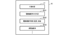
- the CPU 6B reads and executes the control program according to the third embodiment of the memory 6C as shown in FIG. I will provide a.
- This function includes a stroke determination unit 17 (FIG. 12: functions as a process determination unit) that determines the stroke of the internal combustion engine 3.
- the control unit 6 operates the rotating electrical machine 4 as an electric motor (see FIG. 12, block B32).
- the rotating electrical machine 4 is operated as an electric motor in the second half of the compression stroke, the entire explosion stroke, and the first half of the exhaust stroke, for which the assist of the internal combustion engine 3 is considered to be particularly effective.
- the control unit 6 operates the rotating electrical machine 4 as a generator (see FIG. 12, block B33). Moreover, the control part 6 extends or shortens the period operated as an electric motor according to the charge balance of the battery 2. That is, when it is anticipated that the charge amount of the battery 2 will fall, the control part 6 shortens the period operated as an electric motor. As described above, according to the system 1 of the second embodiment, the operation of the rotating electrical machine 4 is more finely switched between the electric motor and the generator according to the stroke of the internal combustion engine 3, thereby further reducing the fuel consumption. Can be increased.
- the two-phase mode is performed in the explosion stroke and the exhaust stroke that can be expected to be driven by the internal combustion engine 3 during the period of operation as the electric motor, and at other times.
- Implement the three-phase mode Thereby, the cost reduction and size reduction of the system 1 by use of 2 phase mode can be promoted.
- one intermediate tap 8U, 8V, 8W is provided for each phase.
- two or more intermediate taps 8U to 8W are provided, and the intermediate taps 8U to 8W are provided.
- the number of inverters 5 may be increased in accordance with the increase in the number of 8W.
- the intermediate taps 8U to 8W are provided in the windings 7U to 7W of the rotating electrical machine 4, and a plurality of inverters 5 are connected to the windings 7U to 7W.
- the actual number for each phase can be changed by turning on and off the relay switch in the windings 7U to 7W of each phase. You may make it increase / decrease the number of turns.
- the windings 7U to 7W of the embodiment for example, the windings 7U1 and 7U2 are connected in series in the winding 7U, and the actual number of turns of the windings 7U1 and 7U2 is assumed to be the same n.
- the manner of the windings 7U to 7W is not limited to this.
- the winding 7U1 may be provided by connecting two windings having an actual number of turns n in parallel.
- the number of poles of the rotor and the number of stators of the rotating electrical machine 4 are not limited to 12 poles and 18 poles, which are typical for a three-phase motor generator, and a delta ( ⁇ ) connection as a winding connection system. May be adopted.
- timing of switching the operation of the rotating electrical machine 4 between the electric motor and the generator is not limited to the embodiment, and may be switched at a constant time interval or may be switched according to the temperature condition or the like.
- the control unit 6 may execute the next short-circuit mode. That is, the short-circuit mode is a control mode in which the induced voltage of the windings 7U to 7W is short-circuited to the ground by an inverter operation, and is different from the control mode in which the rotating electrical machine 4 is operated as an electric motor or a generator.
- the switches Sun1, Svn1, Swn1 may be turned on to short-circuit the generated current, and the switches Sun1, Svn1, Swn1
- the switches Sun2, Svn2, and Swn2 may be turned on.
- the generated current generated in the windings 7U1, 7U2, 7V1, and 7V2 is short-circuited, it is possible to short-circuit by turning on the switches Sun1 and Svn1, but in addition to the switches Sun1 and Svn1, the switch Sun2, By turning on Svn2, it is possible to disperse the heat generated at the time of a short circuit and to increase the braking ability.
- the power generation, travel assist, and engine brake may be optimized by adjusting the degree of the power appropriately by PWM control or the like.
- the short-circuit mode may be executed at regular intervals regardless of the stroke of the internal combustion engine 3.
- the mode in which none of the first to third patterns is executed is illustrated as the two-phase mode.
- at least one of the first to third patterns of the three-phase mode is illustrated. It may not be executed.
- the two-phase mode may be partially realized by adopting the fourth pattern and repeating three patterns of the fourth, second, and third patterns.
Landscapes
- Engineering & Computer Science (AREA)
- Mechanical Engineering (AREA)
- Chemical & Material Sciences (AREA)
- Combustion & Propulsion (AREA)
- Transportation (AREA)
- General Engineering & Computer Science (AREA)
- Automation & Control Theory (AREA)
- Power Engineering (AREA)
- Control Of Ac Motors In General (AREA)
- Electric Propulsion And Braking For Vehicles (AREA)
- Hybrid Electric Vehicles (AREA)
Priority Applications (1)
| Application Number | Priority Date | Filing Date | Title |
|---|---|---|---|
| CN201680020380.2A CN107531232B (zh) | 2015-04-07 | 2016-04-07 | 电动机装置 |
Applications Claiming Priority (2)
| Application Number | Priority Date | Filing Date | Title |
|---|---|---|---|
| JP2015078198A JP6492901B2 (ja) | 2015-04-07 | 2015-04-07 | 電動機装置 |
| JP2015-078198 | 2015-04-07 |
Publications (1)
| Publication Number | Publication Date |
|---|---|
| WO2016163459A1 true WO2016163459A1 (ja) | 2016-10-13 |
Family
ID=57073241
Family Applications (1)
| Application Number | Title | Priority Date | Filing Date |
|---|---|---|---|
| PCT/JP2016/061401 Ceased WO2016163459A1 (ja) | 2015-04-07 | 2016-04-07 | 電動機装置 |
Country Status (3)
| Country | Link |
|---|---|
| JP (1) | JP6492901B2 (enExample) |
| CN (1) | CN107531232B (enExample) |
| WO (1) | WO2016163459A1 (enExample) |
Families Citing this family (1)
| Publication number | Priority date | Publication date | Assignee | Title |
|---|---|---|---|---|
| US11414065B2 (en) * | 2018-12-17 | 2022-08-16 | Quantentech Limited | Hybrid electric vehicle system and control method |
Citations (5)
| Publication number | Priority date | Publication date | Assignee | Title |
|---|---|---|---|---|
| JP2001271759A (ja) * | 2000-03-24 | 2001-10-05 | Tokico Ltd | 空気圧縮機およびその制御方法 |
| JP2005057818A (ja) * | 2003-08-01 | 2005-03-03 | Aisin Aw Co Ltd | 電動駆動制御装置、電動駆動制御方法及びそのプログラム |
| JP2007288858A (ja) * | 2006-04-13 | 2007-11-01 | Sharp Corp | モータ制御装置、冷蔵庫、空気調和機 |
| JP2012130220A (ja) * | 2010-12-17 | 2012-07-05 | Aisin Aw Co Ltd | 回転電機制御装置 |
| JP2014058825A (ja) * | 2012-09-18 | 2014-04-03 | Hitachi Constr Mach Co Ltd | 建設機械 |
Family Cites Families (6)
| Publication number | Priority date | Publication date | Assignee | Title |
|---|---|---|---|---|
| WO1998036930A1 (fr) * | 1997-02-20 | 1998-08-27 | Honda Giken Kogyo Kabushiki Kaisha | Generatrice/moteur pour moteur a combustion interne |
| JP2005110470A (ja) * | 2003-10-02 | 2005-04-21 | Toshiba Kyaria Kk | 電動機の運転制御装置 |
| JP4643508B2 (ja) * | 2006-07-13 | 2011-03-02 | 本田技研工業株式会社 | 電動機の制御装置 |
| EP2677134B1 (en) * | 2006-11-15 | 2016-03-23 | Mitsubishi Electric Corporation | Automotive hybrid engine assist system |
| JP4978429B2 (ja) * | 2007-11-01 | 2012-07-18 | アイシン・エィ・ダブリュ株式会社 | 電動機制御装置,電気自動車およびハイブリッド電気自動車 |
| RU2550813C2 (ru) * | 2013-07-18 | 2015-05-20 | Российская Федерация, От Имени Которой Выступает Министерство Промышленности И Торговли Российской Федерации | Способ управления мотор-генератором |
-
2015
- 2015-04-07 JP JP2015078198A patent/JP6492901B2/ja active Active
-
2016
- 2016-04-07 WO PCT/JP2016/061401 patent/WO2016163459A1/ja not_active Ceased
- 2016-04-07 CN CN201680020380.2A patent/CN107531232B/zh active Active
Patent Citations (5)
| Publication number | Priority date | Publication date | Assignee | Title |
|---|---|---|---|---|
| JP2001271759A (ja) * | 2000-03-24 | 2001-10-05 | Tokico Ltd | 空気圧縮機およびその制御方法 |
| JP2005057818A (ja) * | 2003-08-01 | 2005-03-03 | Aisin Aw Co Ltd | 電動駆動制御装置、電動駆動制御方法及びそのプログラム |
| JP2007288858A (ja) * | 2006-04-13 | 2007-11-01 | Sharp Corp | モータ制御装置、冷蔵庫、空気調和機 |
| JP2012130220A (ja) * | 2010-12-17 | 2012-07-05 | Aisin Aw Co Ltd | 回転電機制御装置 |
| JP2014058825A (ja) * | 2012-09-18 | 2014-04-03 | Hitachi Constr Mach Co Ltd | 建設機械 |
Also Published As
| Publication number | Publication date |
|---|---|
| JP2016201861A (ja) | 2016-12-01 |
| JP6492901B2 (ja) | 2019-04-03 |
| CN107531232B (zh) | 2020-01-07 |
| CN107531232A (zh) | 2018-01-02 |
Similar Documents
| Publication | Publication Date | Title |
|---|---|---|
| US9979329B2 (en) | Power converting device and power converting system | |
| US8053915B2 (en) | On-vehicle rotary electric machine operating on two modes of rectification | |
| CN108696215B (zh) | 发动机发电机 | |
| RU2660963C1 (ru) | Схема и способ управления ею | |
| CN108111089B (zh) | 开关磁阻马达用的控制装置 | |
| JP2017079580A (ja) | 回転電機の制御装置 | |
| JP4655431B2 (ja) | 車両用発電電動機装置 | |
| JP5008749B2 (ja) | 電源装置 | |
| JP5174617B2 (ja) | 回転電機装置及びその制御装置 | |
| JP5441979B2 (ja) | 電力変換器の制御装置および制御方法 | |
| JP6492901B2 (ja) | 電動機装置 | |
| JP2004320861A (ja) | 車両用3相電動発電機の制御装置 | |
| CN107534409B (zh) | 电动发电机装置 | |
| JP2004129379A (ja) | モータ制御装置、およびモータの駆動制御をコンピュータに実行させるためのプログラムを記録したコンピュータ読取り可能な記録媒体 | |
| JP6541844B1 (ja) | 回転電機の制御装置 | |
| JP4943719B2 (ja) | スイッチトリラクタンスモータの回生制御装置 | |
| JP4983939B2 (ja) | 同期電動機の駆動装置 | |
| JP7185480B2 (ja) | 電力変換装置 | |
| JP2018113784A (ja) | 電力変換回路の制御装置、回転電機ユニット | |
| JP6645405B2 (ja) | 回転電機の制御装置、回転電機ユニット | |
| JP2016201861A5 (enExample) | ||
| JP6058085B1 (ja) | 回転電機および回転電機の制御方法 | |
| US10483897B2 (en) | Switched reluctance motor system, and method of controlling switched reluctance motor system | |
| JP6948844B2 (ja) | エンジンの始動装置 | |
| JP2008245495A (ja) | スイッチドリラクタンスモータの制御装置 |
Legal Events
| Date | Code | Title | Description |
|---|---|---|---|
| 121 | Ep: the epo has been informed by wipo that ep was designated in this application |
Ref document number: 16776625 Country of ref document: EP Kind code of ref document: A1 |
|
| NENP | Non-entry into the national phase |
Ref country code: DE |
|
| 122 | Ep: pct application non-entry in european phase |
Ref document number: 16776625 Country of ref document: EP Kind code of ref document: A1 |