WO2016163459A1 - 電動機装置 - Google Patents
電動機装置 Download PDFInfo
- Publication number
- WO2016163459A1 WO2016163459A1 PCT/JP2016/061401 JP2016061401W WO2016163459A1 WO 2016163459 A1 WO2016163459 A1 WO 2016163459A1 JP 2016061401 W JP2016061401 W JP 2016061401W WO 2016163459 A1 WO2016163459 A1 WO 2016163459A1
- Authority
- WO
- WIPO (PCT)
- Prior art keywords
- electric motor
- phase
- mode
- motor device
- internal combustion
- Prior art date
- Legal status (The legal status is an assumption and is not a legal conclusion. Google has not performed a legal analysis and makes no representation as to the accuracy of the status listed.)
- Ceased
Links
Images



Classifications
-
- B—PERFORMING OPERATIONS; TRANSPORTING
- B60—VEHICLES IN GENERAL
- B60W—CONJOINT CONTROL OF VEHICLE SUB-UNITS OF DIFFERENT TYPE OR DIFFERENT FUNCTION; CONTROL SYSTEMS SPECIALLY ADAPTED FOR HYBRID VEHICLES; ROAD VEHICLE DRIVE CONTROL SYSTEMS FOR PURPOSES NOT RELATED TO THE CONTROL OF A PARTICULAR SUB-UNIT
- B60W10/00—Conjoint control of vehicle sub-units of different type or different function
- B60W10/04—Conjoint control of vehicle sub-units of different type or different function including control of propulsion units
- B60W10/08—Conjoint control of vehicle sub-units of different type or different function including control of propulsion units including control of electric propulsion units, e.g. motors or generators
-
- B—PERFORMING OPERATIONS; TRANSPORTING
- B60—VEHICLES IN GENERAL
- B60W—CONJOINT CONTROL OF VEHICLE SUB-UNITS OF DIFFERENT TYPE OR DIFFERENT FUNCTION; CONTROL SYSTEMS SPECIALLY ADAPTED FOR HYBRID VEHICLES; ROAD VEHICLE DRIVE CONTROL SYSTEMS FOR PURPOSES NOT RELATED TO THE CONTROL OF A PARTICULAR SUB-UNIT
- B60W20/00—Control systems specially adapted for hybrid vehicles
-
- F—MECHANICAL ENGINEERING; LIGHTING; HEATING; WEAPONS; BLASTING
- F02—COMBUSTION ENGINES; HOT-GAS OR COMBUSTION-PRODUCT ENGINE PLANTS
- F02N—STARTING OF COMBUSTION ENGINES; STARTING AIDS FOR SUCH ENGINES, NOT OTHERWISE PROVIDED FOR
- F02N11/00—Starting of engines by means of electric motors
- F02N11/04—Starting of engines by means of electric motors the motors being associated with current generators
-
- F—MECHANICAL ENGINEERING; LIGHTING; HEATING; WEAPONS; BLASTING
- F02—COMBUSTION ENGINES; HOT-GAS OR COMBUSTION-PRODUCT ENGINE PLANTS
- F02N—STARTING OF COMBUSTION ENGINES; STARTING AIDS FOR SUCH ENGINES, NOT OTHERWISE PROVIDED FOR
- F02N11/00—Starting of engines by means of electric motors
- F02N11/08—Circuits specially adapted for starting of engines
-
- H—ELECTRICITY
- H02—GENERATION; CONVERSION OR DISTRIBUTION OF ELECTRIC POWER
- H02P—CONTROL OR REGULATION OF ELECTRIC MOTORS, ELECTRIC GENERATORS OR DYNAMO-ELECTRIC CONVERTERS; CONTROLLING TRANSFORMERS, REACTORS OR CHOKE COILS
- H02P27/00—Arrangements or methods for the control of AC motors characterised by the kind of supply voltage
- H02P27/04—Arrangements or methods for the control of AC motors characterised by the kind of supply voltage using variable-frequency supply voltage, e.g. inverter or converter supply voltage
- H02P27/06—Arrangements or methods for the control of AC motors characterised by the kind of supply voltage using variable-frequency supply voltage, e.g. inverter or converter supply voltage using DC to AC converters or inverters
-
- Y—GENERAL TAGGING OF NEW TECHNOLOGICAL DEVELOPMENTS; GENERAL TAGGING OF CROSS-SECTIONAL TECHNOLOGIES SPANNING OVER SEVERAL SECTIONS OF THE IPC; TECHNICAL SUBJECTS COVERED BY FORMER USPC CROSS-REFERENCE ART COLLECTIONS [XRACs] AND DIGESTS
- Y02—TECHNOLOGIES OR APPLICATIONS FOR MITIGATION OR ADAPTATION AGAINST CLIMATE CHANGE
- Y02T—CLIMATE CHANGE MITIGATION TECHNOLOGIES RELATED TO TRANSPORTATION
- Y02T10/00—Road transport of goods or passengers
- Y02T10/10—Internal combustion engine [ICE] based vehicles
- Y02T10/40—Engine management systems
Definitions
- the present disclosure relates to a vehicle electric motor device that assists the output of an internal combustion engine such as a vehicle engine.
- Patent Document 1 discloses an electric motor device including a plurality of three-phase bridge circuits as switching means for turning on and off energization of windings of each phase of a rotating electrical machine.
- the semiconductor switch which a some 3 phase bridge circuit has is comprised by 1 chip
- tip MOSFET tip MOSFET
- Patent Documents 2 to 5 do not directly describe the achievement of cost reduction and downsizing of the electric motor device, but the outline is abbreviated.
- the number of turns energized by power supply from the battery (hereinafter referred to as the actual number of turns) is set in order to enable optimal control according to the load to be driven of the electric motor device. It can be changed for each phase by relay switch. As a result, for example, when low-speed and high-torque output is required, the number of actual turns per phase is increased, and when high-speed and low-torque output is required, the number of actual turns per phase is decreased, resulting in low to high rotation. It is said that it is possible to improve the workability by generating torque.
- Patent Document 4 discloses a configuration in which the maximum torque of the starter motor, which is a rotating electrical machine, is set to 60% or less of the “compressed maximum cranking torque” in the engine starter. With this configuration, drivability can be improved by reducing the inertial mass. Furthermore, Patent Document 5 states that, in an electric motor device including a wound field type rotating electrical machine, safety can be improved by making the limit value of the field current variable according to the rotational speed.
- An object of the present disclosure is to promote cost reduction and downsizing in an electric motor device for a vehicle.
- the electric motor device includes a rotating electric machine having a three-phase winding, a switch for turning on and off the application of voltage to the winding, and giving an instruction to the switch to operate the rotating electric machine.
- the electric motor device is for a vehicle, and based on control by the control means, power is supplied from a battery to operate the rotating electric machine as an electric motor, and assists the output of the internal combustion engine by the output generated by the operation as the electric motor.
- the electric motor device includes a rotation speed detection means for detecting the rotation speed of the internal combustion engine
- the control means has the following two-phase mode and three-phase mode. That is, in the three-phase mode, the first combination (W, U), the second combination (the combination of the windings that become the high potential side when the battery voltage is applied to the three-phase windings (U to W) ( U, V) and the third combination (V, W) are sequentially repeated.
- the two-phase mode is a mode in which at least one combination is not executed among the first combination (W, U), the second combination (U, V), and the third combination (V, W).
- the control means has a first threshold for the rotational speed of the internal combustion engine, and uses the two-phase mode when the value detected by the rotational speed detection means is larger than the first threshold.
- the two-phase mode it is possible to reduce the power consumption necessary for operating the rotating electrical machine as an electric motor, and to suppress heat generation by distributing the energization to the switches and windings. . Further, even if the rotational driving force of the rotating electrical machine decreases due to the use of the two-phase mode, the reverse rotation and the stop can be prevented by using the rotation of the rotating electrical machine by the internal combustion engine. For this reason, cost reduction and size reduction can be promoted in the electric motor apparatus for vehicles.
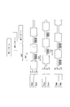
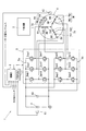
- FIG. 1 is an overall configuration diagram illustrating an electric motor device according to a first embodiment.
- FIG. 2A is a transition diagram showing transition of on / off of the switch in the large mode operation of the first embodiment;
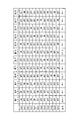
- FIG. 2B is a table showing an example of combinations of switches that are turned on and off in the operation of the inverter of the first embodiment.
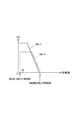
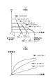
- FIG. 3 shows the correlation between the rotational speed and torque when the rotating electrical machine of the first embodiment is operated as an electric motor.
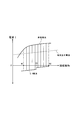
- FIG. 4 is a characteristic diagram showing an operation example of the electric motor apparatus according to the first embodiment.
- FIG. 5 is an overall configuration diagram showing the electric motor device of the second embodiment, FIG.
- FIG. 6 is a table showing combinations of switches that are turned on and off in the operation of the inverter of the second embodiment.
- FIG. 7A is a diagram showing the correlation between the rotational speed and the torque when the rotating electrical machine of the second embodiment is operated as an electric motor
- FIG. 7B is the rotation of the second embodiment. It is a diagram showing the correlation between the rotational speed and the generated current when the electric machine is operated as a generator
- FIG. 8 is an overall configuration diagram showing the electric motor device of the third embodiment
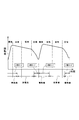
- FIG. 9 is a time chart showing the switching transition of the electric motor and the generator according to the stroke of the internal combustion engine of the third embodiment
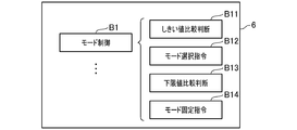
- FIG. 10 is a block diagram for explaining a part of the function of the control unit in the first embodiment.
- FIG. 11 is a block diagram for explaining a part of the function of the control unit in the second embodiment.
- FIG. 12 is a block diagram for explaining a part of the function of the control unit in the third embodiment.
- An electric motor device (hereinafter referred to as a system) 1 is provided in a vehicle and generates an output by feeding power from an in-vehicle battery (hereinafter simply referred to as a battery 2) to start the internal combustion engine 3. It assists the output of the internal combustion engine 3 or charges the battery 2 with a voltage induced by the driving force of the internal combustion engine 3, and has both functions of an electric motor and a generator.
- the system 1 is provided with the following rotary electric machines 4, the inverter 5, and the control part (functioning as a control means) 6.
- the rotating electrical machine 4 operates as an electric motor that starts the internal combustion engine 3 or assists the output of the internal combustion engine 3 or a generator that charges the battery 2.
- U-phase, V-phase, and W-phase windings 7U, 7V, and 7W are star-connected to a stator, and a permanent magnet is built into the rotor.
- the rotor of the rotating electrical machine 4 is directly connected to the crankshaft of the internal combustion engine 3.
- the rotating electrical machine 4 is provided with a position sensor 4a for detecting the magnet position of the rotor.
- the position sensor 4a includes three hall sensors PU, PV, and PW arranged at the stator pole intervals. Become.
- the inverter 5 is a three-phase bridge circuit in which two semiconductor switches are connected in series and three series connections of two semiconductor switches are connected in parallel (hereinafter, the semiconductor switch is referred to as a switch S). ).
- the semiconductor switch is referred to as a switch S.
- one terminal connected in series is connected to the positive electrode of the battery 2, and the other terminal is connected to the ground. Further, the three midpoints of the series connection are connected to the U terminal 9U, the V terminal 9V, and the W terminal 9W, respectively.
- a smoothing capacitor 10 is connected to the inverter 5 in parallel.
- the switch S is, for example, an N channel type power MOSFET.
- the high potential side switch S and the low potential side switch S are respectively referred to as switches Sup and Sun.
- the high potential side switch S and the low potential side switch S may be referred to as switches Svp and Svn, respectively.
- the high potential side switch S and the low potential side switch S may be referred to as switches Swp and Swn, respectively.
- control unit (control means) 6 is an electronic control unit (ECU) that controls the operation of the rotating electrical machine 4.
- the control unit 6 includes, for example, an input circuit 6A that processes an input signal, a CPU 6B (Central Processing Unit) that performs control processing and arithmetic processing based on the input signal, and is necessary for control processing and arithmetic processing.
- Various memories 6C that store and hold data, programs, and the like, an output circuit 6D that outputs necessary signals based on the processing results of the CPU 6A, and the like.
- control unit 6 selects one of the six switches S of the inverter 5 that is sequentially turned on and off, and the switch that is to be sequentially turned on and off in order to control the operation of the rotating electrical machine 4. Change S.
- control part 6 has the following 3 phase mode and 2 phase mode as a control mode which operates the rotary electric machine 4 as an electric motor (refer FIG. 2B).
- FIG. 2A shows the on / off transition of the switch S in the operation as an electric motor, with the rotational speed Ne of the internal combustion engine 3 as the horizontal axis
- FIG. 2B shows the three-phase and two-phase modes, respectively.
- 1 shows an example of a combination of the six switches S that are turned on and off.
- the three-phase mode is a well-known three-phase motor drive mode in which a voltage is applied to the windings 7U to 7W, and the winding that becomes the high potential side when the voltage of the battery 2 is applied to the windings 7U to 7W.
- the following first to third combinations are repeated as combinations of 7U to 7W.
- the first combination is a combination in which the windings 7W and 7U are on the high potential side, and is realized by the first pattern of FIG. 2B.
- the second combination is a combination in which the windings 7U and 7V have a high potential, and is realized by the second pattern in FIG. 2B.
- the third combination is a combination in which the windings 7V and 7W have a high potential, and is realized by the third pattern in FIG. 2B.
- the two-phase mode is a mode in which at least one of the first to third combinations is not executed.
- FIG. 2B illustrates four modes (shown as two-phase modes 1 to 4) in which none of the first to third combinations is executed as the two-phase mode.
- the two-phase mode 1 by repeating the fourth, fifth and twentieth patterns, only the winding 7U is on the high potential side, and a voltage is applied to the windings 7U and 7V. Only a state where a voltage is applied to the windings 7V and 7W and a state where no voltage is applied to any of the windings 7U to 7W is repeated.
- the system 1 includes a rotation speed detector 12 (functioning as a rotation speed detection means) that detects the rotation speed of the internal combustion engine 3.
- the control unit 6 has a first threshold value C0 set in advance in the memory 6C with respect to the rotational speed of the internal combustion engine 3.
- the CPU 6B reads a control program stored in advance in the memory 6C and executes it as a given main routine or subroutine based on the first threshold value C0 and the value detected by the rotation speed detector 12.
- the first threshold value C0> the lowest frequency that can be driven by the internal combustion engine 3 is set.
- the control unit 6 controls the drive of the inverter 5 through the execution of the control program by the CPU 6B, and exhibits the mode control function B1 schematically shown in FIG.
- the control unit 6 uses the mode control function B1 to determine whether the value detected by the rotation speed detector 12 is greater than the first threshold value C0 and equal to or less than the limit rotation speed (threshold comparison determination B11).
- the limit rotational speed refers to a limit rotational speed that can be rotationally driven as an electric motor.
- the control unit 6 uses the same function B1 to select either the three-phase mode or the two-phase mode when the value detected by the rotation speed detector 12 is larger than the first threshold value C0 and equal to or less than the limit rotation speed. (Mode selection command B12).
- the rotational speed detector 12 is a crank angle sensor having a known structure that detects the crank angle of the internal combustion engine 3, for example. In other words, the rotational speed detector 12 detects the crank angle with a protrusion provided on the outer periphery of the crankshaft, and is used for ignition control and fuel injection control of the internal combustion engine 3.
- the correlation between the rotational speed and the torque when using the two-phase mode is lower than that when using the three-phase mode and is slightly faster.
- the control unit 6 determines whether or not the detected rotational speed is equal to or lower than the lower limit value using the mode control function B1 (lower limit value comparison determination B13). Is fixed to the three-phase mode (mode fixing command B14).
- the 2-phase mode 1, the 2-phase mode 2, and the 2-phase mode 3 may be sequentially switched. That is, the two-phase mode 1 ⁇ the two-phase mode 2 ⁇ the two-phase mode 3 may be sequentially repeated.
- energization to the windings 7U to 7W and the switch S can be dispersed, and heat generation can be suppressed. For this reason, since the emitted-heat amount concerned when the rotation speed of the internal combustion engine 3 is high can be reduced, size reduction and cost reduction of an apparatus can be achieved.
- control unit 6 controls the charging of the battery 2 by the parasitic diode associated with the semiconductor switch S that is not selected to be turned on by the operation on the inverter 5.
- the switches S selected to be turned on are the switches Sup and Svn, and the windings 7U and 7V are supplied with power from the battery 2.
- the voltage induced in the winding 7W can charge the battery 2 while being regulated by a parasitic diode associated with the switch Swp by turning the switch Swn on and off (for example, FIG. 2A). (See the circled inside.)
- FIG. 4 exemplifies operating characteristics when the rotational speed of the internal combustion engine 3 changes between N1 and N2.
- the horizontal axis represents the rotational speed Ne of the internal combustion engine 3
- the vertical axis represents the current I flowing between the battery 2 and the inverter 5, and the direction of flow when operating as a generator is positive.
- the currents flowing as the generator and the motor are called the generated current and the motor current, respectively, and are indicated by solid lines.
- a current flowing through another electric load is called an electric load current and indicated by a dotted line.
- the generated current is controlled to be larger than the electric load current.
- the three-phase mode or the two-phase mode is selected in the range of the rotational speed of the internal combustion engine 3 that is smaller than the first threshold value C0 and equal to or higher than the lower limit value.
- the rotational speed of the internal combustion engine 3 is larger than the first threshold value C0
- the three-phase mode or the two-phase mode is selected in the same manner when the rotational speed is equal to or lower than the limit rotational speed.
- the three-phase mode is fixedly selected.
- the rotational speed Ne and the current I travel between the solid line of the generated current and the solid line of the motor current in accordance with the rotational speed of the internal combustion engine 3 and the charge balance of the battery 2. .
- the control unit 6 has a three-phase mode and a two-phase mode, and the two-phase mode when the value detected by the rotation speed detector 12 is larger than the first threshold value C0.
- Use mode As a result, by using the two-phase mode, it is possible to reduce the power consumption required to operate the rotating electrical machine 4 as an electric motor, and partially omit the energization of the switch S and the windings 7U to 7W. By doing so, heat generation can be suppressed.
- the control unit 6 controls charging of the battery 2 by a parasitic diode associated with the semiconductor switch S that is not selected to be turned on by the inverter operation. Thereby, charging efficiency can be improved.
- the system 1 of the second embodiment is used.
- the description will focus on the configuration different from that of the system 1 of the first embodiment, and the same configurations as those described in the first embodiment are denoted by the same reference numerals, and the description thereof is omitted. Simplify.
- the system 1 of the second embodiment as shown in FIG. 5, by providing intermediate taps 8U, 8V, and 8W on the windings 7U to 7W, the actual number of turns can be made variable for each phase.
- the actual number of turns refers to the number of turns in each of the windings 7U to 7W that is energized by power supply from the battery 2 in the operation as an electric motor, or the induced voltage in the operation as a generator. This is the number of turns of the part to be supplied. For this reason, in the windings 7U to 7W of the rotating electrical machine 4, the resistance value of a portion that is energized by power supply from the battery 2 in the operation as an electric motor or a portion that supplies an induced voltage to the battery 2 in the operation as a generator. Is variable.
- winding 7U two windings 7U1 and 7U2 are connected in series, and an intermediate tap 8U is provided at a connection portion between the windings 7U1 and 7U2.
- winding 7V two windings 7V1 and 7V2 are connected in series, and an intermediate tap 8V is provided at a connection portion between the winding 7V1 and the winding 7V2.
- winding 7W two windings 7W1 and 7W2 are connected in series, and an intermediate tap 8W is provided at a connection portion between the winding 7W1 and the winding 7W2.
- the windings 7U1, 7U2, 7V1, 7V2, 7W1, and 7W2 all have the same number of turns, and the terminals that do not form the intermediate taps 8U, 8V, and 8W in the windings 7U2, 7V2, and 7W2, respectively. Connected.
- terminals on which the intermediate taps 8U, 8V, and 8W are not formed in the windings 7U1, 7V1, and 7W1 are referred to as a U terminal 9U, a V terminal 9V, and a W terminal 9W, respectively.
- the number of turns of the windings 7U1, 7U2, 7V1, 7V2, 7W1, and 7W2 are all set to the same integer n for the sake of simplicity.
- the system 1 of the second embodiment includes two inverters 5.
- the inverters 5 are both three-phase bridge circuits in which two switches S are connected in series and three series connections of two semiconductor switches S are connected in parallel.
- one terminal connected in series is connected to the positive electrode of the battery 2, and the other terminal is connected to the ground. Further, the three midpoints of the series connection are connected to the U terminal 9U, the V terminal 9V, and the W terminal 9W, respectively.
- one terminal connected in series is connected to the positive electrode of the battery 2, and the other terminal is connected to the ground. Further, the three midpoints of the series connection are respectively connected to the intermediate taps 8U, 8V, and 8W (hereinafter, the inverter 5 connected to the U terminal 9U, the V terminal 9V, and the W terminal 9W is referred to as an inverter 5a.
- the inverter 5 connected to 8U, 8V, and 8W may be called the inverter 5b.).
- the semiconductor switch S is, for example, an N channel type power MOSFET.
- the high potential side switch S and the low potential side switch S are respectively referred to as switches Sup1, Sun1.
- switches Svp1 and Svn1 are respectively referred to as switches Svp1 and Svn1, respectively.
- the high potential side switch S and the low potential side switch S may be referred to as switches Swp1 and Swn1, respectively.
- the high-potential side and low-potential side switches S are referred to as switches Sup2 and Sun2, respectively.
- switches Sup2 and Sun2 are referred to as switches Sup2 and Sun2, respectively.
- switches Svp2 and Svn2 are referred to as switches Svp2 and Svn2, respectively.
- switches Swp2 and Swn2 are referred to as switches Swp2 and Swn2, respectively.
- the control unit 6 selects one of the 12 switches S included in the inverters 5a and 5b that is sequentially turned on and off, and the switch that should be selected sequentially. S is changed (hereinafter, one of the twelve switches S that is sequentially turned on / off is selected, and the operation that sequentially changes the switch S to be selected may be referred to as an inverter operation).
- control part 6 changes the number of real turns for every phase by performing inverter operation. More specifically, the control unit 6 selects from three numerical values of 2n, 3n, and 4n regarding the actual number of turns in all phases in the inverter operation. For example, when power is supplied to the windings 7U and 7V in the operation as an electric motor, if the switches Sup1 and Svn1 are selected to be turned on, the windings 7U1, 7U2, 7V1 and 7V2 are supplied with power from the battery 2, The actual number of turns for each V phase is 2n and 2n, and the actual number of turns for all phases is 4n.
- the windings 7U2 and 7V2 are supplied with power from the battery 2, so that the actual turn numbers of the U phase and the V phase are n and n, respectively, The number is 2n.
- the windings 7U1, 7U2 and 7V2 are supplied with power from the battery 2, so that the actual number of turns in the U phase and V phase is 2n and n, respectively.
- the actual number of turns is 3n.
- the windings 7U2, 7V1 and 7V2 are supplied with power from the battery 2, so that the actual number of turns of the U phase and the V phase is n and 2n, respectively.
- the actual number of turns is 3n.
- the inverter operation the actual number of turns in all phases when voltage is applied from the battery 2 to the two phases of the three-phase windings 7U to 7W or the induced voltage is supplied to the battery 2 from the two phases.
- the modes for selecting 4n, 2n, and 3n are referred to as a large mode, a small mode, and a medium mode, respectively, from the viewpoint of the magnitude of drive energy.
- the system 1 there are three-phase and two-phase mode divisions and large, small and medium mode divisions. That is, in the system 1, as an inverter operation option, three-phase mode and large mode, three-phase mode and small mode, three-phase mode and medium mode, two-phase mode and large mode, two-phase mode and small mode, and two-phase mode There are six modes of the medium mode.
- FIG. 6 shows combinations of the 12 switches S that are turned on and off in each of the three-phase mode and large mode, the three-phase mode and small mode, the three-phase mode and medium mode. That is, in the three-phase mode and the large mode and the three-phase mode and the small mode, the seventh to ninth patterns and the tenth to twelfth patterns are sequentially repeated, respectively. In the three-phase mode and the medium mode, the thirteenth to fifteenth patterns or the sixteenth to eighteenth patterns are sequentially repeated.
- the two-phase mode and large mode, the two-phase mode and small mode, and the two-phase mode and medium mode are the same as the two-phase modes 1 to 4 in the first embodiment, and will not be described.
- the correlation between the rotational speed and the torque when the rotating electrical machine 4 is operated as an electric motor, and the correlation between the rotational speed and the generated current when the rotating electrical machine 4 is operated as a generator are three-phase mode and large.
- FIG. 7 shows, for example, each of the mode, the three-phase mode and the medium mode, the three-phase mode and the small mode.
- the correlations of the two-phase mode and the large mode, the two-phase mode and the medium mode, the two-phase mode and the small mode are also shown.
- the large mode when operating as an electric motor, the large mode is suitable for assisting when the rotational speed of the internal combustion engine 3 is in the middle speed range from the low rotational speed, and the medium mode is the rotational speed of the internal combustion engine 3.
- the low mode is suitable for assisting when the rotational speed of the internal combustion engine 3 is in a high rotational speed region near 5000 rpm.
- the large mode in the operation as a generator, the large mode has a large number of actual turns, so that the induced voltage becomes high and can be charged even when the rotational speed of the internal combustion engine 3 is low.
- the internal combustion engine 3 can be charged at a medium speed or higher, and in the small mode, the internal combustion engine 3 can be charged at a high speed or higher.
- the system 1 of the second embodiment includes a voltage detector 15 (functioning as a voltage detection means) that detects the voltage of the battery 2.
- the voltage detector 15 is provided as an A / D conversion circuit having a known structure, for example.
- control unit 6 executes the inverter operation by selecting one of the large, small, and medium modes according to the detection values of the rotation speed detector 12 and the voltage detector 15, and the rotating electric machine 4 is driven by the electric motor. Or operate as a generator.
- control unit 6 rotates based on the charge balance of the battery 2 predicted using the change over time of the detection value by the voltage detector 15 or the detection value by the voltage detector 15 when starting the internal combustion engine 3. It is determined whether or not the electric machine 4 is operated as an electric motor.
- the control unit 6 2 when the estimated charge balance of the battery 2 is negative, or when the detected value of the voltage of the battery 2 when starting the internal combustion engine 3 is lower than the reference value, the control unit 6 2 is regarded as having a high necessity of charging, and the rotating electrical machine 4 is controlled to operate as a generator, and the rotating electrical machine 4 is not operated as an electric motor. That is, the control unit 6 selects the actual number of turns so that the voltage induced in the windings 7U to 7W is higher than the voltage of the battery 2, and operates as a generator.
- the control unit 6 has second threshold values C1 and C2 (C1 ⁇ C2) set in advance for the rotational speed of the internal combustion engine 3 for each phase.
- the relationship between the rotation speed and the threshold is “Lower limit rotation speed (lower limit value) that can be rotated ⁇ first threshold value C0 ⁇ Second threshold C1 for three-phase mode ⁇ second C2 for two-phase mode ⁇ It is in the relationship of the limit rotation speed which can be rotated in a small mode (3 phase mode and 2 phase mode).
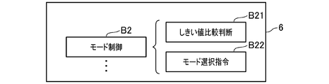
- the control unit 6 When operating the rotating electrical machine 4 as an electric motor, the control unit 6 changes the actual number of turns for each phase according to the result of comparison between the detected value by the rotational speed detector 12 and the threshold values C1 and C2. Specifically, the control unit 6 obtains a mode selection function B2 as schematically shown in FIG. 11 by executing a control program of the CPU 6B. For this reason, the mode selection function B2 makes a comparison judgment between the detection value by the rotation speed detector 12 and the lower limit rotation speed, one second threshold value C1, the other second threshold value C2, and the limit rotation speed ( Threshold comparison judgment B21).
- control unit 6 selects the inverters 5a and 5b from the combinations of the three-phase / two-phase mode and the large / medium / small mode for each rotation speed range based on the threshold comparison judgment through the mode selection function B2. Are selectively commanded (mode selection command B22).
- the drive mode is selected from a total of three types of modes: a large mode of the three-phase mode, a medium mode, and a small mode
- a large mode of the three-phase mode When it is determined that the detected rotational speed is within the range of the lower limit rotational speed or more and less than one second threshold C1, a total of 6 large modes, medium modes, and small modes in each of the three-phase mode and the two-phase mode 6
- the drive mode is selected from the types of modes, When it is determined that the detected rotational speed falls within the range of one second threshold C1 or more and less than the other second threshold C2, a total of 4 medium modes and small modes of the three-phase mode and the two-phase mode, respectively.
- the drive mode is selected from the types of modes, ⁇
- the three-phase mode and the small mode of each of the two-phase modes A mode is selected.
- Arbitrary mode is employ
- the control unit 6 when the detection value by the rotational speed detector 12 is larger than one second threshold value C1 and smaller than the other second threshold value C2, the control unit 6 has a three-phase mode and a two-phase mode, respectively.
- the middle mode or the small mode is adopted to operate the rotating electric machine 4 as an electric motor.
- the internal combustion engine 3 is assisted with an arbitrary output of medium-speed medium torque or medium-speed small torque.
- the control unit 6 employs the three-phase mode or the small mode of the two-phase mode to operate the rotating electrical machine 4 as an electric motor when the value detected by the rotation speed detector 12 is larger than the other second threshold value C2. .
- the internal combustion engine 3 assists with an arbitrary output during high speed or high speed and low torque.
- the rotating electrical machine 4 makes the actual number of turns variable for each phase by providing the intermediate taps 14 in the windings 7U to 7W of each phase.
- the control unit 6 selects one of the switches S included in the two inverters 5a and 5b that is sequentially turned on and off, and executes an inverter operation that sequentially changes the switch S to be selected, thereby rotating the control unit 6
- the operation of the electric machine 4 is controlled.
- the control part 6 changes the number of real turns for every phase by performing inverter operation.
- FIG. 11 shows functions provided when the CPU 6B reads and executes the control program according to the second embodiment of the memory 6C, that is, the functional blocks of the control unit 6.
- the number of actual turns can be increased or decreased at high speed for each phase, so that the output of the motor or generator can be changed at high speed, or the operation of the rotating electrical machine 4 can be switched between the motor and generator at high speed. Can be. For this reason, in the system 1, the fuel consumption reduction effect can be enhanced.
- control unit 6 has second threshold values C1 and C2 with respect to the rotational speed of the internal combustion engine 3, and according to the result of comparison between the detected value by the rotational speed detector 12 and the second threshold values C1 and C2. Change the actual number of turns for each phase. Thereby, the output of the rotary electric machine 4 can be changed at high speed with respect to the load fluctuation of the internal combustion engine 3.
- control unit 6 rotates based on the charge balance of the battery 2 predicted by using the change with time of the detection value by the voltage detector 15 or the detection value by the voltage detector 15 when starting the internal combustion engine 3. It is determined whether or not the electric machine 4 is operated as an electric motor. Thereby, the influence which the voltage fluctuation of the battery 2 by operating the rotary electric machine 4 as an electric motor has on other electric loads can be reduced.
- FIG. 1 A system 1 according to a third embodiment will be described.
- the description will focus on the configuration different from the system 1 of the second embodiment, and the same components as those described in the second embodiment will be denoted by the same reference numerals, and the description thereof will be omitted. Simplify.
- the CPU 6B reads and executes the control program according to the third embodiment of the memory 6C as shown in FIG. I will provide a.
- This function includes a stroke determination unit 17 (FIG. 12: functions as a process determination unit) that determines the stroke of the internal combustion engine 3.
- the control unit 6 operates the rotating electrical machine 4 as an electric motor (see FIG. 12, block B32).
- the rotating electrical machine 4 is operated as an electric motor in the second half of the compression stroke, the entire explosion stroke, and the first half of the exhaust stroke, for which the assist of the internal combustion engine 3 is considered to be particularly effective.
- the control unit 6 operates the rotating electrical machine 4 as a generator (see FIG. 12, block B33). Moreover, the control part 6 extends or shortens the period operated as an electric motor according to the charge balance of the battery 2. That is, when it is anticipated that the charge amount of the battery 2 will fall, the control part 6 shortens the period operated as an electric motor. As described above, according to the system 1 of the second embodiment, the operation of the rotating electrical machine 4 is more finely switched between the electric motor and the generator according to the stroke of the internal combustion engine 3, thereby further reducing the fuel consumption. Can be increased.
- the two-phase mode is performed in the explosion stroke and the exhaust stroke that can be expected to be driven by the internal combustion engine 3 during the period of operation as the electric motor, and at other times.
- Implement the three-phase mode Thereby, the cost reduction and size reduction of the system 1 by use of 2 phase mode can be promoted.
- one intermediate tap 8U, 8V, 8W is provided for each phase.
- two or more intermediate taps 8U to 8W are provided, and the intermediate taps 8U to 8W are provided.
- the number of inverters 5 may be increased in accordance with the increase in the number of 8W.
- the intermediate taps 8U to 8W are provided in the windings 7U to 7W of the rotating electrical machine 4, and a plurality of inverters 5 are connected to the windings 7U to 7W.
- the actual number for each phase can be changed by turning on and off the relay switch in the windings 7U to 7W of each phase. You may make it increase / decrease the number of turns.
- the windings 7U to 7W of the embodiment for example, the windings 7U1 and 7U2 are connected in series in the winding 7U, and the actual number of turns of the windings 7U1 and 7U2 is assumed to be the same n.
- the manner of the windings 7U to 7W is not limited to this.
- the winding 7U1 may be provided by connecting two windings having an actual number of turns n in parallel.
- the number of poles of the rotor and the number of stators of the rotating electrical machine 4 are not limited to 12 poles and 18 poles, which are typical for a three-phase motor generator, and a delta ( ⁇ ) connection as a winding connection system. May be adopted.
- timing of switching the operation of the rotating electrical machine 4 between the electric motor and the generator is not limited to the embodiment, and may be switched at a constant time interval or may be switched according to the temperature condition or the like.
- the control unit 6 may execute the next short-circuit mode. That is, the short-circuit mode is a control mode in which the induced voltage of the windings 7U to 7W is short-circuited to the ground by an inverter operation, and is different from the control mode in which the rotating electrical machine 4 is operated as an electric motor or a generator.
- the switches Sun1, Svn1, Swn1 may be turned on to short-circuit the generated current, and the switches Sun1, Svn1, Swn1
- the switches Sun2, Svn2, and Swn2 may be turned on.
- the generated current generated in the windings 7U1, 7U2, 7V1, and 7V2 is short-circuited, it is possible to short-circuit by turning on the switches Sun1 and Svn1, but in addition to the switches Sun1 and Svn1, the switch Sun2, By turning on Svn2, it is possible to disperse the heat generated at the time of a short circuit and to increase the braking ability.
- the power generation, travel assist, and engine brake may be optimized by adjusting the degree of the power appropriately by PWM control or the like.
- the short-circuit mode may be executed at regular intervals regardless of the stroke of the internal combustion engine 3.
- the mode in which none of the first to third patterns is executed is illustrated as the two-phase mode.
- at least one of the first to third patterns of the three-phase mode is illustrated. It may not be executed.
- the two-phase mode may be partially realized by adopting the fourth pattern and repeating three patterns of the fourth, second, and third patterns.
Landscapes
- Engineering & Computer Science (AREA)
- Mechanical Engineering (AREA)
- Chemical & Material Sciences (AREA)
- Combustion & Propulsion (AREA)
- Transportation (AREA)
- General Engineering & Computer Science (AREA)
- Automation & Control Theory (AREA)
- Power Engineering (AREA)
- Control Of Ac Motors In General (AREA)
- Electric Propulsion And Braking For Vehicles (AREA)
- Hybrid Electric Vehicles (AREA)
Abstract
電動機装置(1)は、3相の巻線(7U~7W)を有する回転電機(4)と、巻線(7U~7W)への電圧の印加をオンオフするスイッチ(S)と、このスイッチ(S)に指令を与えて回転電機(4)の動作を制御する制御手段(6)と、内燃機関(3)の回転数を検出する回転数検出手段(12)とを備える。制御手段(6)は、3相の巻線(7U~7W)に電圧を印加する3つの態様を順次実施する3相モード、および3つの態様の中から2つの態様を選択して繰り返し実施する2相モードを有する。制御手段(6)は、内燃機関(3)の回転数に対する第1の閾値(C0)を有し、回転数検出手段(12)による検出値が前記第1の閾値(C0)よりも大きいときに、2相モードを使用する。
Description
本出願は、2015年4月7日に出願された日本出願番号2015-078198号に基づくもので、ここにその記載内容を援用する。
本開示は、車両エンジン等の内燃機関の出力をアシストする車両用の電動機装置に関する。
従来から、回転電機を電動機として動作させる電動機装置では、コストダウンおよび小型化を進めるべく、様々な取り組みがなされている。
例えば、特許文献1では、回転電機の各相の巻線への通電をオン、オフするスイッチング手段として、複数の3相ブリッジ回路を備える電動機装置が開示されている。
例えば、特許文献1では、回転電機の各相の巻線への通電をオン、オフするスイッチング手段として、複数の3相ブリッジ回路を備える電動機装置が開示されている。
また、特許文献1の電動機装置では、複数の3相ブリッジ回路が有する半導体スイッチを1チップのMOSFETで構成し、それぞれの3相ブリッジ回路はスイッチングタイミングが互いにずれるように制御される。
これにより、特許文献1では、半導体スイッチのターンオフによる電流遮断時の過渡的なチップ温度の上昇を抑制することができるので、電動機装置のコストダウンおよび小型化を達成することができるとしている。
これにより、特許文献1では、半導体スイッチのターンオフによる電流遮断時の過渡的なチップ温度の上昇を抑制することができるので、電動機装置のコストダウンおよび小型化を達成することができるとしている。
しかし、電動機装置のコストダウンおよび小型化の要請は高く、特に、内燃機関の出力をアシストする車両用の電動機装置では、更なるコストダウンおよび小型化に対する要請が極めて高い。このため、電動機装置のコストダウンおよび小型化に関し、更なる改善策が求められている。
なお、以下の特許文献2~5は、電動機装置のコストダウンおよび小型化の達成を直接的に述べていないが、概要を略記する。
なお、以下の特許文献2~5は、電動機装置のコストダウンおよび小型化の達成を直接的に述べていないが、概要を略記する。
まず、特許文献2、3は、電動機装置の駆動対象の負荷に応じて最適な制御を可能とするため、バッテリからの給電により通電されるターン数(以下、実ターン数と呼ぶ。)を、リレースイッチにより相毎で変更可能とする。
これにより、例えば、低速高トルクの出力が必要なときには、相毎の実ターン数を増やし、高速低トルクの出力が必要なときには、相毎の実ターン数を減らすことで、低回転から高回転までトルクの発生を可能にして作業性を改善することができるとしている。
これにより、例えば、低速高トルクの出力が必要なときには、相毎の実ターン数を増やし、高速低トルクの出力が必要なときには、相毎の実ターン数を減らすことで、低回転から高回転までトルクの発生を可能にして作業性を改善することができるとしている。
次に、特許文献4は、エンジン始動装置において、回転電機であるスタータモータの最大トルクを「圧縮乗り越し最大クランキングトルク」の60%以下に設定する構成を開示する。そして、この構成により、慣性マスを低減してドライバビリティを改善することができるとしている。
さらに、特許文献5は、巻線界磁型の回転電機を備える電動機装置において、界磁電流の制限値を回転速度に応じて可変にすることで、安全性を高めることができるとしている。
さらに、特許文献5は、巻線界磁型の回転電機を備える電動機装置において、界磁電流の制限値を回転速度に応じて可変にすることで、安全性を高めることができるとしている。
本開示の目的は、車両用の電動機装置において、コストダウンおよび小型化を促進することにある。
本開示の第一の態様において、電動機装置は、3相の巻線を有する回転電機と、巻線への電圧の印加をオン、オフするスイッチと、スイッチに指令を与えて回転電機の動作を制御する制御手段とを備える。また、電動機装置は、車両用であり、制御手段による制御に基づき、バッテリから給電して回転電機を電動機として動作させるとともに、電動機としての動作により発生する出力によって内燃機関の出力をアシストする。
また、電動機装置は、内燃機関の回転数を検出する回転数検出手段を備え、制御手段は、次の2相モードおよび3相モードを有する。
すなわち、3相モードは、3相の巻線(U~W)にバッテリの電圧を印加するときに高電位側になる巻線の組合せとして、第1組合せ(W、U)、第2組合せ(U、V)および第3組合せ(V、W)を順次繰り返すモードである。また、2相モードは、第1組合せ(W、U)、第2組合せ(U、V)および第3組合せ(V、W)の内、少なくとも1つの組合せを実行しないモードである。さらに、制御手段は、内燃機関の回転数に対する第1の閾値を有し、回転数検出手段による検出値が第1の閾値よりも大きいときに、2相モードを使用する。
すなわち、3相モードは、3相の巻線(U~W)にバッテリの電圧を印加するときに高電位側になる巻線の組合せとして、第1組合せ(W、U)、第2組合せ(U、V)および第3組合せ(V、W)を順次繰り返すモードである。また、2相モードは、第1組合せ(W、U)、第2組合せ(U、V)および第3組合せ(V、W)の内、少なくとも1つの組合せを実行しないモードである。さらに、制御手段は、内燃機関の回転数に対する第1の閾値を有し、回転数検出手段による検出値が第1の閾値よりも大きいときに、2相モードを使用する。
これにより、2相モードを使用することで、回転電機を電動機として動作させるのに必要な消費電力を低減することができるとともに、スイッチや巻線への通電を分散させて発熱を抑えることができる。また、2相モードの使用により回転電機の回転駆動力が低下しても、内燃機関による回転電機の連れ回しを利用することで、逆転や停止を防止することができる。このため、車両用の電動機装置において、コストダウンおよび小型化を促進することができる。
本開示についての上記目的およびその他の目的、特徴や利点は、添付の図面を参照しながら下記の詳細な記述により、より明確になる。その図面は、
図1は、第1の実施例の電動機装置を示す全体構成図であり、
図2Aは、第1の実施例の大モードの動作におけるスイッチのオンオフの推移を示す推移図であり、
図2Bは、第1の実施例のインバータに対する操作においてスイッチの内、オンオフするものの組合せの一例を示す表であり、
図3は、第1の実施例の回転電機を電動機として動作させたときの回転数とトルクとの相関であり、
図4は、第1の実施例の電動機装置の動作例を示す特性図であり、
図5は、第2の実施例の電動機装置を示す全体構成図であり、
図6は、第2の実施例のインバータに対する操作においてスイッチの内、オンオフするものの組合せを示す表であり、
図7(a)は、第2の実施例の回転電機を電動機として動作させたときの回転数とトルクとの相関を示す図であり、図7(b)は、第2の実施例の回転電機を発電機として動作させたときの回転数と発電電流との相関を示す図であり、
図8は、第3の実施例の電動機装置を示す全体構成図であり、
図9は、第3の実施例の内燃機関の行程別の電動機と発電機との切替推移を示すタイムチャートであり、
図10は、第1の実施例における制御部の機能の一部を説明するブロック図であり、
図11は、第2の実施例における制御部の機能の一部を説明するブロック図であり、
図12は、第3の実施例における制御部の機能の一部を説明するブロック図である。
以下、発明を実施するための形態を、実施例を用いて説明する。なお、実施例は具体的な一例を開示するものであり、本発明が実施例に限定されないことは言うまでもない。
〔第1の実施例〕
第1の実施例の電動機装置1の構成を、図1を用いて説明する。
電動機装置(以下、システムと呼ぶ。)1は、車両に設けられるものであり、車載バッテリ(以下、単にバッテリ2と呼ぶ。)からの給電により出力を発生させて内燃機関3を始動したり、内燃機関3の出力をアシストしたり、内燃機関3の駆動力により誘起される電圧によってバッテリ2を充電したりするものであり、電動機と発電機の機能を両方併せ持つ。
そして、システム1は、以下の回転電機4、インバータ5、および、制御部(制御手段として機能する)6を備える。
第1の実施例の電動機装置1の構成を、図1を用いて説明する。
電動機装置(以下、システムと呼ぶ。)1は、車両に設けられるものであり、車載バッテリ(以下、単にバッテリ2と呼ぶ。)からの給電により出力を発生させて内燃機関3を始動したり、内燃機関3の出力をアシストしたり、内燃機関3の駆動力により誘起される電圧によってバッテリ2を充電したりするものであり、電動機と発電機の機能を両方併せ持つ。
そして、システム1は、以下の回転電機4、インバータ5、および、制御部(制御手段として機能する)6を備える。
まず、回転電機4は、内燃機関3を始動したり、内燃機関3の出力をアシストしたりする電動機、または、バッテリ2を充電する発電機として動作するものである。回転電機4は、例えば、固定子にU相、V相およびW相の3相の巻線7U、7V、7Wがスター結線され、回転子に永久磁石が内蔵されたものである。
なお、回転電機4の回転子は、内燃機関3のクランクシャフトに直結されている。また、回転電機4には、回転子の磁石位置を検出する位置センサ4aが付設されており、位置センサ4aは、固定子の極間隔で配置された3個のホールセンサPU、PV、PWからなる。
なお、回転電機4の回転子は、内燃機関3のクランクシャフトに直結されている。また、回転電機4には、回転子の磁石位置を検出する位置センサ4aが付設されており、位置センサ4aは、固定子の極間隔で配置された3個のホールセンサPU、PV、PWからなる。
次に、インバータ5は、2つの半導体スイッチが直列に接続し、かつ、2つの半導体スイッチの直列接続が3つ並列に接続した3相ブリッジ回路である(以下、半導体スイッチをスイッチSと呼ぶ。)。
そして、インバータ5では、直列接続の一方の端子がバッテリ2のプラス極に接続するとともに、他方の端子がアースに接続している。さらに、直列接続の3つの中点がそれぞれU端子9U、V端子9V、W端子9Wに接続している。
また、インバータ5には平滑コンデンサ10が並列に接続している。さらに、スイッチSは、例えば、Nチャネル型のパワーMOSFETである。
そして、インバータ5では、直列接続の一方の端子がバッテリ2のプラス極に接続するとともに、他方の端子がアースに接続している。さらに、直列接続の3つの中点がそれぞれU端子9U、V端子9V、W端子9Wに接続している。
また、インバータ5には平滑コンデンサ10が並列に接続している。さらに、スイッチSは、例えば、Nチャネル型のパワーMOSFETである。
以下の説明では、インバータ5の3つの直列接続の内、中点がU端子9Uに接続するものに含まれる2つのスイッチSに関し、高電位側、低電位側のスイッチSをそれぞれスイッチSup、Sunと呼ぶことがある。また、中点がV端子9Vに接続するものに含まれる2つのスイッチSに関し、高電位側、低電位側のスイッチSをそれぞれスイッチSvp、Svnと呼ぶことがある。さらに、中点がW端子9Wに接続するものに含まれる2つのスイッチSに関し、高電位側、低電位側のスイッチSをそれぞれスイッチSwp、Swnと呼ぶことがある。
次に、制御部(制御手段)6は、回転電機4の動作を制御する電子制御ユニット(ECU:Electronic Control Unit)である。制御部6は、例えば、入力された信号を処理する入力回路6A、入力された信号に基づき制御処理や演算処理を行うCPU6B(Central Processing Unit:中央処理装置)、制御処理や演算処理に必要なデータやプログラム等を記憶して保持する各種のメモリ6C、CPU6Aの処理結果に基づき必要な信号を出力する出力回路6D等を有する。
また、制御部6は、回転電機4の動作を制御するため、インバータ5が有する6個のスイッチSの中から、逐次、オン、オフするものを選択するとともに、逐次、オン、オフすべきスイッチSを変更する。
そして、制御部6は、回転電機4を電動機として動作させる制御モードとして、次の3相モード、および、2相モードを有する(図2B参照。)。
ここで、図2Aは、電動機としての動作におけるスイッチSのオン、オフの推移を、内燃機関3の回転数Neを横軸として示すものであり、図2Bは、3相、2相モードのそれぞれにおいて、6個のスイッチSの内、オン、オフするものの組合せの一例を示すものである。
ここで、図2Aは、電動機としての動作におけるスイッチSのオン、オフの推移を、内燃機関3の回転数Neを横軸として示すものであり、図2Bは、3相、2相モードのそれぞれにおいて、6個のスイッチSの内、オン、オフするものの組合せの一例を示すものである。
まず、3相モードは、巻線7U~7Wへ電圧を印加する周知の3相電動機の駆動モードであり、巻線7U~7Wにバッテリ2の電圧を印加するときに高電位側になる巻線7U~7Wの組合せとして、次の第1~第3組合せを繰り返すモードである。
ここで、第1組合せは巻線7W、7Uが高電位側になる組合せであり、図2Bの第1パターンにより実現する。また、第2組合せは巻線7U、7Vが高電位なる組合せであり、図2Bの第2パターンにより実現する。さらに、第3組合せは巻線7V、7Wが高電位なる組合せであり、図2Bの第3パターンにより実現する。
ここで、第1組合せは巻線7W、7Uが高電位側になる組合せであり、図2Bの第1パターンにより実現する。また、第2組合せは巻線7U、7Vが高電位なる組合せであり、図2Bの第2パターンにより実現する。さらに、第3組合せは巻線7V、7Wが高電位なる組合せであり、図2Bの第3パターンにより実現する。
次に、2相モードは、第1~第3組合せの内、少なくとも1つの組合せを実行しないモードである。ここで、図2Bには、2相モードとして、第1~第3組合せをいずれも実行しない4つのモード(2相モード1~4として図示している。)を例示している。
まず、2相モード1は、第4、第5、第20パターンを繰り返し実施することにより、巻線7Uのみ高電位側にあって巻線7U、7Vへ電圧が印加される状態、巻線7Vのみ高電位側にあって巻線7V、7Wへ電圧が印加される状態、および、巻線7U~7Wのいずれにも電圧が印加されない状態を繰り返す。
まず、2相モード1は、第4、第5、第20パターンを繰り返し実施することにより、巻線7Uのみ高電位側にあって巻線7U、7Vへ電圧が印加される状態、巻線7Vのみ高電位側にあって巻線7V、7Wへ電圧が印加される状態、および、巻線7U~7Wのいずれにも電圧が印加されない状態を繰り返す。
また、2相モード2は、第20、第5、第6パターンを繰り返し実施することにより、巻線7U~7Wのいずれにも電圧が印加されない状態、巻線7Vのみ高電位側にあって巻線7V、7Wへ電圧が印加される状態と、巻線7Wのみ高電位側にあって巻線7W、7Uへ電圧が印加される状態とを繰り返す。
また、2相モード3は、第4、第20、第6パターンを繰り返し実施することにより、巻線7Uのみ高電位側にあって巻線7U、7Vへ電圧が印加される状態、巻線7U~7Wのいずれにも電圧が印加されない状態、および、巻線7Wのみ高電位側にあって巻線7W、7Uへ電圧が印加される状態を繰り返す。
さらに、2相モード4は、第4~第6パターンを繰り返し実施することにより、巻線7Uのみ高電位側にあって巻線7U、7Vへ電圧が印加される状態、巻線7Vのみ高電位側にあって巻線7V、7Wへ電圧が印加される状態、および、巻線7Wのみ高電位側にあって巻線7W、7Uへ電圧が印加される状態を繰り返す。
そして、2相モード1~4では、巻線7U~7Wの何れにも電圧を印加しない期間が繰り返し現れる。このため、2相モード1~4では、巻線7U~7Wの何れにも電圧を印加しない状態において、内燃機関3による連れ回しを利用して電動機としての回転を維持する。
さらに、システム1は、内燃機関3の回転数を検出する回転数検出器12(回転数検出手段として機能する)を備える。制御部6は、内燃機関3の回転数に対する予めメモリ6Cに設定された第1の閾値C0を有する。CPU6Bは、予めメモリ6Cに格納された制御プログラムを読み出し、第1の閾値C0と回転数検出器12による検出値とに基づき、与えられたメインルーチンやサブルーチンとして実行する。ここでは、第1の閾値C0>内燃機関3による連れ回しが可能な最低周波数に設定されている。
CPU6Bによる制御プログラムの実行を介して、制御部6は、インバータ5の駆動を制御し、図10に模式的に示すモード制御機能B1を発揮する。
この制御部6は、モード制御機能B1を使って、回転数検出器12による検出値が第1の閾値C0よりも大きく且つ限界回転数以下であるか否かを判断する(閾値比較判断B11)。ここで、限界回転数とは、電動機として回転駆動可能な限界の回転数を言う。制御部6は、同機能B1を使って、回転数検出器12による検出値が第1の閾値C0よりも大きく且つ限界回転数以下であるときには、3相モード又は2相モードの何れかを選択して指令する(モード選択指令B12)。
この制御部6は、モード制御機能B1を使って、回転数検出器12による検出値が第1の閾値C0よりも大きく且つ限界回転数以下であるか否かを判断する(閾値比較判断B11)。ここで、限界回転数とは、電動機として回転駆動可能な限界の回転数を言う。制御部6は、同機能B1を使って、回転数検出器12による検出値が第1の閾値C0よりも大きく且つ限界回転数以下であるときには、3相モード又は2相モードの何れかを選択して指令する(モード選択指令B12)。
なお、回転数検出器12は、例えば、内燃機関3のクランク角を検出する周知構造のクランク角センサである。すなわち、回転数検出器12は、クランクシャフトの外周に設けた突起でクランク角を検出するものであり、内燃機関3の点火制御や燃料噴射制御に使用されている。
ここで、図3に示すように、2相モード使用時の回転数とトルクとの相関は、3相モード使用時よりも低トルク、かつ、わずかに高速である。また、2相モード使用時には、内燃機関3による連れ回し可能な回転数に下限値が存在する。そして、回転数がこの下限値以下になると、電動機単体ではトルクが発生しない(回転電機4が回転しない)ので、3相モード固定で回転電機4を制御する必要がある。
このため、制御部6は、モード制御機能B1を使って、検出した回転数が上記下限値以下であるか否かも判断し(下限値比較判断B13)、この判断が肯定される場合、駆動モードを3相モードの固定するように指令する(モード固定指令B14)。
このため、制御部6は、モード制御機能B1を使って、検出した回転数が上記下限値以下であるか否かも判断し(下限値比較判断B13)、この判断が肯定される場合、駆動モードを3相モードの固定するように指令する(モード固定指令B14)。
なお、2相モード使用時には、2相モード1、2相モード2、2相モード3を順次切り替えてもよい。すなわち、2相モード1→2相モード2→2相モード3を順次繰り返すようにしてもよい。この場合、巻線7U~7WやスイッチSへの通電を分散させることができ、発熱を抑制することができる。このため、内燃機関3の回転数が高いときに懸念される発熱量を低減することができるので、装置の小型化やコストダウンを達成することができる。
また、制御部6は、インバータ5に対する操作でオンすべきものとして選択されていない半導体スイッチSに付随する寄生ダイオードによるバッテリ2の充電を制御する。例えば、第1パターンを選択している場合、オンすべきものとして選択されているスイッチSは、スイッチSup、Svnであり、巻線7U、7Vにバッテリ2から給電される。このため、例えば、巻線7Wに誘起される電圧は、スイッチSwnをオン、オフ操作することでスイッチSwpに付随する寄生ダイオードによりレギュレートしながらバッテリ2に充電することができる(例えば、図2A中の丸で囲った部分を参照。)。
ここで、システム1の動作特性の一例を、図4を用いて説明する。
図4は、内燃機関3の回転数がN1とN2との間で推移する場合の、動作特性を例示したものである。図4において横軸は内燃機関3の回転数Neを示し、縦軸はバッテリ2とインバータ5との間に流れる電流Iを示し、発電機として動作する場合に流れる方向をプラスとしている。また、発電機、電動機として流れる電流をそれぞれ発電電流、モータ電流と呼んで実線で示している。さらに、他の電気負荷に流れる電流を電気負荷電流と呼んで点線で示している。
図4は、内燃機関3の回転数がN1とN2との間で推移する場合の、動作特性を例示したものである。図4において横軸は内燃機関3の回転数Neを示し、縦軸はバッテリ2とインバータ5との間に流れる電流Iを示し、発電機として動作する場合に流れる方向をプラスとしている。また、発電機、電動機として流れる電流をそれぞれ発電電流、モータ電流と呼んで実線で示している。さらに、他の電気負荷に流れる電流を電気負荷電流と呼んで点線で示している。
図4によれば、発電機としての動作では、発電電流が電気負荷電流よりも大きくなるように制御される。また、電動機としての動作では、制御アルゴリズムによれば、内燃機関3の回転数が第1の閾値C0よりも小さく且つ下限値以上の回転数の範囲では3相モード又は2相モードが選択される。また、内燃機関3の回転数が第1の閾値C0よりも大きいが、限界回転数以下の場合も同様に、3相モード又は2相モードが選択される。さらに、検出した回転数が下限値未満の場合、3相モードが固定的に選択される。図4は、電動機動作としては、第1の閾値C0よりも小さい領域では3相モードが選択され、一方、第1の閾値C0以上の領域では2相モードが選択される例を示している。
そして、経時的に動作を見ると、回転数Neおよび電流Iは、内燃機関3の回転数やバッテリ2の充電収支に応じて、発電電流の実線と、モータ電流の実線との間を往来する。
そして、経時的に動作を見ると、回転数Neおよび電流Iは、内燃機関3の回転数やバッテリ2の充電収支に応じて、発電電流の実線と、モータ電流の実線との間を往来する。
〔第1の実施例の効果〕
第1の実施例のシステム1によれば、制御部6は、3相モードおよび2相モードを有し、回転数検出器12による検出値が第1の閾値C0よりも大きいときに、2相モードを使用する。
これにより、2相モードを使用することで、回転電機4を電動機として動作させるのに必要な消費電力を低減することができるとともに、スイッチSや巻線7U~7Wへの通電を部分的に省略することで発熱を抑えることができる。また、2相モードの使用により回転電機4の回転駆動力が低下しても、内燃機関3による回転電機4の連れ回しを利用することで、逆転や停止を防止することができる。このため、システム1において、コストダウンおよび小型化を促進することができる。
第1の実施例のシステム1によれば、制御部6は、3相モードおよび2相モードを有し、回転数検出器12による検出値が第1の閾値C0よりも大きいときに、2相モードを使用する。
これにより、2相モードを使用することで、回転電機4を電動機として動作させるのに必要な消費電力を低減することができるとともに、スイッチSや巻線7U~7Wへの通電を部分的に省略することで発熱を抑えることができる。また、2相モードの使用により回転電機4の回転駆動力が低下しても、内燃機関3による回転電機4の連れ回しを利用することで、逆転や停止を防止することができる。このため、システム1において、コストダウンおよび小型化を促進することができる。
また、回転電機4の回転子は、内燃機関3のクランクシャフトに直結されているので、内燃機関3による回転電機4の連れ回しを効果的に利用することができる。
さらに、制御部6は、インバータ操作でオンすべきものとして選択されていない半導体スイッチSに付随する寄生ダイオードによるバッテリ2の充電を制御する。これにより、充電効率を高めることができる。
さらに、制御部6は、インバータ操作でオンすべきものとして選択されていない半導体スイッチSに付随する寄生ダイオードによるバッテリ2の充電を制御する。これにより、充電効率を高めることができる。
〔第2の実施例〕
第2の実施例のシステム1をする。この第2の実施例において、第1の実施例のシステム1と異なる構成を中心に説明し、第1の実施例で説明した構成と同じ構成には同一符号を用いて、その説明を省略又は簡略化する。
第2の実施例のシステム1によれば、図5に示すように、巻線7U~7Wに中間タップ8U、8V、8Wを設けることで、実ターン数を相毎で可変にしている。
第2の実施例のシステム1をする。この第2の実施例において、第1の実施例のシステム1と異なる構成を中心に説明し、第1の実施例で説明した構成と同じ構成には同一符号を用いて、その説明を省略又は簡略化する。
第2の実施例のシステム1によれば、図5に示すように、巻線7U~7Wに中間タップ8U、8V、8Wを設けることで、実ターン数を相毎で可変にしている。
なお、実ターン数とは、巻線7U~7Wのそれぞれの内、電動機としての動作においてバッテリ2からの給電により通電される部分のターン数、または、発電機としての動作において誘起電圧をバッテリ2に供給する部分のターン数である。
このため、回転電機4の巻線7U~7Wでは、電動機としての動作においてバッテリ2からの給電により通電される部分、または、発電機としての動作において誘起電圧をバッテリ2に供給する部分の抵抗値が可変である。
このため、回転電機4の巻線7U~7Wでは、電動機としての動作においてバッテリ2からの給電により通電される部分、または、発電機としての動作において誘起電圧をバッテリ2に供給する部分の抵抗値が可変である。
具体的には、巻線7Uでは、2つの巻線7U1、7U2が直列接続しており、巻線7U1と、7U2との接続部に中間タップ8Uが設けられている。同様に、巻線7Vでは、2つの巻線7V1、7V2が直列接続しており、巻線7V1と、巻線7V2との接続部に中間タップ8Vが設けられている。巻線7Wでは、2つの巻線7W1、7W2が直列接続しており、巻線7W1と、巻線7W2との接続部に中間タップ8Wが設けられている。これにより、回転電機4では、実ターン数を相毎に可変となっている。
また、巻線7U1、7U2、7V1、7V2、7W1、7W2は全て互に同一ターン数であり、巻線7U2、7V2、7W2のそれぞれにおいて中間タップ8U、8V、8Wを形成しない方の端子がスター結線されている。
なお、以下の説明では、巻線7U1、7V1、7W1のそれぞれにおいて中間タップ8U、8V、8Wを形成しない方の端子を、U端子9U、V端子9V、W端子9Wとする。また、巻線7U1、7U2、7V1、7V2、7W1、7W2のそれぞれのターン数を、説明を簡単にするため、全て同一の整数nとする。
なお、以下の説明では、巻線7U1、7V1、7W1のそれぞれにおいて中間タップ8U、8V、8Wを形成しない方の端子を、U端子9U、V端子9V、W端子9Wとする。また、巻線7U1、7U2、7V1、7V2、7W1、7W2のそれぞれのターン数を、説明を簡単にするため、全て同一の整数nとする。
次に、第2の実施例のシステム1は、インバータ5を2つ備える。
また、インバータ5は、両方とも、2つのスイッチSが直列に接続し、かつ、2つの半導体スイッチSの直列接続が3つ並列に接続した3相ブリッジ回路である。
また、インバータ5は、両方とも、2つのスイッチSが直列に接続し、かつ、2つの半導体スイッチSの直列接続が3つ並列に接続した3相ブリッジ回路である。
そして、一方のインバータ5では、直列接続の一方の端子がバッテリ2のプラス極に接続するとともに、他方の端子がアースに接続し、ている。さらに、直列接続の3つの中点がそれぞれU端子9U、V端子9V、W端子9Wに接続している。また、他方のインバータ5では、直列接続の一方の端子がバッテリ2のプラス極に接続するとともに、他方の端子がアースに接続し、ている。さらに、直列接続の3つの中点がそれぞれ中間タップ8U、8V、8Wに接続している(以下、U端子9U、V端子9V、W端子9Wに接続するインバータ5をインバータ5aと呼び、中間タップ8U、8V、8Wに接続するインバータ5をインバータ5bと呼ぶことがある。)。
なお、インバータ5には平滑コンデンサが並列に接続している。また、半導体スイッチSは、例えば、Nチャネル型のパワーMOSFETである。
以下の説明では、インバータ5aの3つの直列接続の内、中点がU端子9Uに接続するものに含まれる2つのスイッチSに関し、高電位側、低電位側のスイッチSをそれぞれスイッチSup1、Sun1と呼ぶことがある。また、中点がV端子9Vに接続するものに含まれる2つのスイッチSに関し、高電位側、低電位側のスイッチSをそれぞれスイッチSvp1、Svn1と呼ぶことがある。さらに、中点がW端子9Wに接続するものに含まれる2つのスイッチSに関し、高電位側、低電位側のスイッチSをそれぞれスイッチSwp1、Swn1と呼ぶことがある。
以下の説明では、インバータ5aの3つの直列接続の内、中点がU端子9Uに接続するものに含まれる2つのスイッチSに関し、高電位側、低電位側のスイッチSをそれぞれスイッチSup1、Sun1と呼ぶことがある。また、中点がV端子9Vに接続するものに含まれる2つのスイッチSに関し、高電位側、低電位側のスイッチSをそれぞれスイッチSvp1、Svn1と呼ぶことがある。さらに、中点がW端子9Wに接続するものに含まれる2つのスイッチSに関し、高電位側、低電位側のスイッチSをそれぞれスイッチSwp1、Swn1と呼ぶことがある。
同様に、インバータ5bの3つの直列接続の内、中点が中間タップ8Uに接続するものに含まれる2つのスイッチSに関し、高電位側、低電位側のスイッチSをそれぞれスイッチSup2、Sun2と呼ぶことがある。また、中点が中間タップ8Vに接続するものに含まれる2つのスイッチSに関し、高電位側、低電位側のスイッチSをそれぞれスイッチSvp2、Svn2と呼ぶことがある。さらに、中点が中間タップ8Wに接続するものに含まれる2つのスイッチSに関し、高電位側、低電位側のスイッチSをそれぞれスイッチSwp2、Swn2と呼ぶことがある。
そして、第2の実施例のシステム1によれば、制御部6は、インバータ5a、5bが有する12個のスイッチSの中から、逐次、オンオフするものを選択するとともに、逐次、選択すべきスイッチSを変更する(以下、12個のスイッチSの中から、逐次、オンオフするものを選択するとともに、逐次、選択すべきスイッチSを変更する操作をインバータ操作と呼ぶことがある。)。
そして、制御部6は、インバータ操作を実行することで、相毎に実ターン数を変更する。より具体的には、制御部6は、インバータ操作において、全相の実ターン数に関し、2n、3n、4nの3つの数値の中から選択する。
例えば、電動機としての動作において巻線7U、7Vに給電する場合、スイッチSup1、Svn1をオンすべきものとして選択すると、巻線7U1、7U2、7V1、7V2にバッテリ2から給電されるので、U相、V相それぞれの実ターン数は2n、2nであり、全相の実ターン数は4nとなる。
例えば、電動機としての動作において巻線7U、7Vに給電する場合、スイッチSup1、Svn1をオンすべきものとして選択すると、巻線7U1、7U2、7V1、7V2にバッテリ2から給電されるので、U相、V相それぞれの実ターン数は2n、2nであり、全相の実ターン数は4nとなる。
また、スイッチSup2、Svn2をオンすべきものとして選択すると、巻線7U2、7V2にバッテリ2から給電されるので、U相、V相それぞれの実ターン数はn、nであり、全相の実ターン数は2nとなる。
また、スイッチSup1、Svn2をオンすべきものとして選択すると、巻線7U1、7U2、7V2にバッテリ2から給電されるので、U相、V相それぞれの実ターン数は2n、nであり、全相の実ターン数は3nとなる。
また、スイッチSup1、Svn2をオンすべきものとして選択すると、巻線7U1、7U2、7V2にバッテリ2から給電されるので、U相、V相それぞれの実ターン数は2n、nであり、全相の実ターン数は3nとなる。
さらに、スイッチSvn1、Sup2をオンすべきものとして選択すると、巻線7U2、7V1、7V2にバッテリ2から給電されるので、U相、V相それぞれの実ターン数はn、2nであり、全相の実ターン数は3nとなる。
以下、インバータ操作において、3相の巻線7U~7Wの内、2相にバッテリ2から電圧を印加したり、2相から誘起電圧をバッテリ2に供給したりするときの全相の実ターン数として4n、2n、3nを選択するモードを、それぞれ、駆動エネルギの大小の観点から、大モード、小モード、中モードと呼ぶ。
以下、インバータ操作において、3相の巻線7U~7Wの内、2相にバッテリ2から電圧を印加したり、2相から誘起電圧をバッテリ2に供給したりするときの全相の実ターン数として4n、2n、3nを選択するモードを、それぞれ、駆動エネルギの大小の観点から、大モード、小モード、中モードと呼ぶ。
以上により、システム1では、3相、2相モードのモード区分、および、大、小、中モードのモード区分が存在することになる。つまり、システム1では、インバータ操作の選択肢として、3相モードかつ大モード、3相モードかつ小モード、3相モードかつ中モード、2相モードかつ大モード、2相モードかつ小モード、2相モードかつ中モードの6通りが存在する。
ここで、図6は、3相モードかつ大モード、3相モードかつ小モード、3相モードかつ中モードのそれぞれにおいて、12個のスイッチSの内、オンオフするものの組合せを示すものである。
すなわち、3相モードかつ大モード、および、3相モードかつ小モードでは、それぞれ、第7~第9パターン、第10~第12パターンが順次繰り返される。また、3相モードかつ中モードでは、第13~第15パターン、または、第16~第18パターンが順次繰り返される。なお、3相モードかつ中モードでは、例えば、第13パターン→第17パターン→第15パターン→第18パターン→のように、第13~第15パターンのグループと、第16~第18パターンのグループとを交互に繰り返すことで、巻線7U~7WやスイッチSの駆動電流による発熱を分散して抑制することができる。
すなわち、3相モードかつ大モード、および、3相モードかつ小モードでは、それぞれ、第7~第9パターン、第10~第12パターンが順次繰り返される。また、3相モードかつ中モードでは、第13~第15パターン、または、第16~第18パターンが順次繰り返される。なお、3相モードかつ中モードでは、例えば、第13パターン→第17パターン→第15パターン→第18パターン→のように、第13~第15パターンのグループと、第16~第18パターンのグループとを交互に繰り返すことで、巻線7U~7WやスイッチSの駆動電流による発熱を分散して抑制することができる。
なお、2相モードかつ大モード、2相モードかつ小モード、および、2相モードかつ中モードに関しては、第1の実施例の2相モード1~4に準じるものであり、説明を省略する。
また、回転電機4を電動機として動作させたときの回転数とトルクとの相関、および、回転電機4を発電機として動作させたときの回転数と発電電流との相関は、3相モードかつ大モード、3相モードかつ中モード、3相モードかつ小モードのそれぞれで、例えば、図7に示すようになる。なお、回転数とトルクとの相関では、2相モードかつ大モード、2相モードかつ中モード、2相モードかつ小モードのそれぞれの相関を併せて示した。
図7によれば、電動機として動作では、大モードは、内燃機関3の回転数が低回転時から中速回転域であるときのアシストに適しており、中モードは、内燃機関3の回転数が、例えば、3000rpm付近の中速域であるときのアシストに適しており、小モードは、内燃機関3の回転数が5000rpm付近以上の高回転域であるときのアシストに適している。
また、図7によれば、発電機として動作では、大モードは、実ターン数が多いことから内燃機関3の回転数が低回転域でも誘起電圧が高くなって充電可能であり、中モードは、内燃機関3の回転数が中速以上で充電可能であり、小モードは、内燃機関3の回転数が高速以上で充電可能である。
また、図7によれば、発電機として動作では、大モードは、実ターン数が多いことから内燃機関3の回転数が低回転域でも誘起電圧が高くなって充電可能であり、中モードは、内燃機関3の回転数が中速以上で充電可能であり、小モードは、内燃機関3の回転数が高速以上で充電可能である。
さらに、第2の実施例のシステム1は、バッテリ2の電圧を検出する電圧検出器15(電圧検出手段として機能する)を備える。なお、電圧検出器15は、例えば、周知構造のA/D変換回路として設けられている。
そして、制御部6は、回転数検出器12および電圧検出器15の検出値に応じて、大、小、中モードの中から1つを選択してインバータ操作を実行し、回転電機4を電動機または発電機として動作させる。
まず、制御部6は、電圧検出器15による検出値の経時変化を用いて予測されるバッテリ2の充電収支、または、内燃機関3を始動するときの電圧検出器15による検出値に基づき、回転電機4を電動機として動作させるか否かを決める。
具体的には、予測されるバッテリ2の充電収支がマイナスである場合、または、内燃機関3を始動するときのバッテリ2の電圧の検出値が基準値よりも低い場合、制御部6は、バッテリ2を充電する必要性が高いものとみなし、回転電機4が発電機として動作するように制御し、回転電機4を電動機として動作させない。つまり、制御部6は、巻線7U~7Wで誘起される電圧がバッテリ2の電圧よりも高くなるように、実ターン数を選択して発電機として動作させる。
次に、制御部6は、図7(a)に示すように、内燃機関3の回転数に対するあらかじめ設定された第2の閾値C1、C2(C1<C2)を相毎に有する。同図に示すように、一例として、回転数と閾値の関係は、
“連れ回り可能な下限回転数(下限値)≦第1の閾値C0
<3相モードに対する第2の閾値C1<2相モードに対する第2のC2
<小モード(3相モード及び2相モード)で回転可能な限界回転数
の関係にある。なお、第2の閾値C1、C2は、それぞれ、トルク=0となる回転数を最大値として設定されていればよく、その最大値以下の値であってもよい。なお、ここでは、第2の閾値C1、C2は、それぞれ、3相モード及び2相モードで同じ値であるものとする(実際には、図7(a)に示すように、トルク=0となる回転数は、3相モードのそれよりも2相モードのそれの方が若干高い)。
“連れ回り可能な下限回転数(下限値)≦第1の閾値C0
<3相モードに対する第2の閾値C1<2相モードに対する第2のC2
<小モード(3相モード及び2相モード)で回転可能な限界回転数
の関係にある。なお、第2の閾値C1、C2は、それぞれ、トルク=0となる回転数を最大値として設定されていればよく、その最大値以下の値であってもよい。なお、ここでは、第2の閾値C1、C2は、それぞれ、3相モード及び2相モードで同じ値であるものとする(実際には、図7(a)に示すように、トルク=0となる回転数は、3相モードのそれよりも2相モードのそれの方が若干高い)。
制御部6は、回転電機4を電動機として動作させる場合、回転数検出器12による検出値と閾値C1、C2との比較の結果に応じて、相毎に実ターン数を変更する。
具体的には、制御部6は、CPU6Bの制御プログラムの実行することにより、図11に模式的に示す如く、モード選択機能B2を得る。このため、このモード選択機能B2によって、回転数検出器12による検出値と下限回転数、一方の第2の閾値C1、他方の第2の閾値C2、及び限界回転数との比較判断を行う(閾値比較判断B21)。さらに、制御部6は、モード選択機能B2を介して、閾値比較判断に基づき、回転数の範囲毎に3相/2相モード及び大/中/小モードの組み合わせの中から、インバータ5a、5bの駆動モードが選択的に指令される(モード選択指令B22)。
具体的には、制御部6は、CPU6Bの制御プログラムの実行することにより、図11に模式的に示す如く、モード選択機能B2を得る。このため、このモード選択機能B2によって、回転数検出器12による検出値と下限回転数、一方の第2の閾値C1、他方の第2の閾値C2、及び限界回転数との比較判断を行う(閾値比較判断B21)。さらに、制御部6は、モード選択機能B2を介して、閾値比較判断に基づき、回転数の範囲毎に3相/2相モード及び大/中/小モードの組み合わせの中から、インバータ5a、5bの駆動モードが選択的に指令される(モード選択指令B22)。
このモード選択指令B22によれば、
・検出回転数が下限回転数未満の場合、3相モードの大モード、中モード、及び小モードの合計3種類のモードの中から駆動モードが選択され、
・検出回転数が下限回転数以上、且つ一方の第2の閾値C1未満の範囲に入ると判断されると、3相モード及び2相モードそれぞれの大モード、中モード、及び小モードの合計6種類のモードの中から駆動モードが選択され、
・検出回転数が一方の第2の閾値C1以上、且つ他方の第2の閾値C2未満の範囲に入ると判断されると、3相モード及び2相モードそれぞれの中モード及び小モードの合計4種類のモードの中から駆動モードが選択され、
・検出回転数が他方の第2の閾値C2以上、且つ限界回転数未満の範囲に入ると判断されると、3相モード及び2相モードそれぞれの小モードの合計2種類のモードの中から駆動モードが選択される。
上述の駆動モードを代表的に言えば、回転数検出器12による検出値が一方の第2の閾値C1よりも小さいときには、3相モード及び2相モードそれぞれの大モード、中モード及び小モードから任意のモードを採用して回転電機4を電動機として動作させる。これにより、内燃機関3は選択された任意のトルクの出力でアシストされる。
・検出回転数が下限回転数未満の場合、3相モードの大モード、中モード、及び小モードの合計3種類のモードの中から駆動モードが選択され、
・検出回転数が下限回転数以上、且つ一方の第2の閾値C1未満の範囲に入ると判断されると、3相モード及び2相モードそれぞれの大モード、中モード、及び小モードの合計6種類のモードの中から駆動モードが選択され、
・検出回転数が一方の第2の閾値C1以上、且つ他方の第2の閾値C2未満の範囲に入ると判断されると、3相モード及び2相モードそれぞれの中モード及び小モードの合計4種類のモードの中から駆動モードが選択され、
・検出回転数が他方の第2の閾値C2以上、且つ限界回転数未満の範囲に入ると判断されると、3相モード及び2相モードそれぞれの小モードの合計2種類のモードの中から駆動モードが選択される。
上述の駆動モードを代表的に言えば、回転数検出器12による検出値が一方の第2の閾値C1よりも小さいときには、3相モード及び2相モードそれぞれの大モード、中モード及び小モードから任意のモードを採用して回転電機4を電動機として動作させる。これにより、内燃機関3は選択された任意のトルクの出力でアシストされる。
また、制御部6は、回転数検出器12による検出値が一方の第2の閾値C1よりも大きく、かつ、他方の第2の閾値C2よりも小さいときには、3相モード及び2相モードそれぞれの中モード又は小モードを採用して回転電機4を電動機として動作させる。これにより、内燃機関3は中速中トルクまたは中速小トルクの任意の出力でアシストされる。
さらに、制御部6は、回転数検出器12による検出値が他方の第2の閾値C2よりも大きいときに3相モード又は2相モードの小モードを採用して回転電機4を電動機として動作させる。これにより、内燃機関3は高速中または高速低トルクの任意の出力でアシストする。
さらに、制御部6は、回転数検出器12による検出値が他方の第2の閾値C2よりも大きいときに3相モード又は2相モードの小モードを採用して回転電機4を電動機として動作させる。これにより、内燃機関3は高速中または高速低トルクの任意の出力でアシストする。
〔第2の実施例の効果〕
このように、第2の実施例のシステム1によれば、回転電機4は、各相の巻線7U~7Wに中間タップ14を設けることで、実ターン数を相毎で可変にしている。
また、制御部6は、2つのインバータ5a、5bが有するスイッチSの中から、逐次、オンオフするものを選択するとともに、逐次、選択すべきスイッチSを変更するインバータ操作を実行することで、回転電機4の動作を制御する。さらに、制御部6は、インバータ操作を実行することで、相毎に実ターン数を変更する。ここで、図11は、CPU6Bがメモリ6Cの、第2の実施例に係る制御プログラムを読み出して実行することにより提供される機能、即ち制御部6の機能ブロックを示す。
このように、第2の実施例のシステム1によれば、回転電機4は、各相の巻線7U~7Wに中間タップ14を設けることで、実ターン数を相毎で可変にしている。
また、制御部6は、2つのインバータ5a、5bが有するスイッチSの中から、逐次、オンオフするものを選択するとともに、逐次、選択すべきスイッチSを変更するインバータ操作を実行することで、回転電機4の動作を制御する。さらに、制御部6は、インバータ操作を実行することで、相毎に実ターン数を変更する。ここで、図11は、CPU6Bがメモリ6Cの、第2の実施例に係る制御プログラムを読み出して実行することにより提供される機能、即ち制御部6の機能ブロックを示す。
これにより、相毎に実ターン数を高速で増減させることができるので、電動機または発電機としての出力を高速で変更したり、回転電機4の動作を電動機と発電機との間で高速で切り替えたりすることができる。このため、システム1において、燃費低減効果を高めることができる。
また、制御部6は、内燃機関3の回転数に対する第2の閾値C1、C2を有し、回転数検出器12による検出値と第2の閾値C1、C2との比較の結果に応じて、相毎に実ターン数を変更する。これにより、内燃機関3の負荷変動に対し、回転電機4の出力を高速で変更することができる。
また、制御部6は、電圧検出器15による検出値の経時変化を用いて予測されるバッテリ2の充電収支、または、内燃機関3を始動するときの電圧検出器15による検出値に基づき、回転電機4を電動機として動作させるか否かを決める。
これにより、回転電機4を電動機として動作させることによるバッテリ2の電圧変動が他の電気負荷に及ぼす影響を低減することができる。
これにより、回転電機4を電動機として動作させることによるバッテリ2の電圧変動が他の電気負荷に及ぼす影響を低減することができる。
〔第3の実施例〕
第3の実施例のシステム1を説明する。この第3の実施例において、第2の実施例のシステム1と異なる構成を中心に説明し、第2の実施例で説明した構成と同じ構成には同一符号を用いて、その説明を省略又は簡略化する。
第3の実施例のシステム1を説明する。この第3の実施例において、第2の実施例のシステム1と異なる構成を中心に説明し、第2の実施例で説明した構成と同じ構成には同一符号を用いて、その説明を省略又は簡略化する。
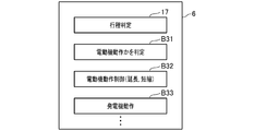
第3の実施例のシステム1の制御部6では、CPU6Bは、図12に示すように、メモリ6Cの、第3の実施例に係る制御プログラムを読み出して実行することにより、制御部6の機能を提供する。この機能には、内燃機関3の行程を判定する行程判定部17(図12:工程判定手段として機能する)も含まれる。行程判定部17、即ち、制御部3は、例えば、回転数検出器12から出力される信号(クランク角を示す信号)、および、内燃機関3の吸気圧を示す信号等により、内燃機関3の行程を判定する。
さらに制御部6は、行程判定部17による判定の結果に応じて、回転電機4を電動機として動作させるか否かを決める(図12、ブロックB31参照)。
さらに制御部6は、行程判定部17による判定の結果に応じて、回転電機4を電動機として動作させるか否かを決める(図12、ブロックB31参照)。
そして、制御部6は、行程判定部17により内燃機関3の行程が少なくとも圧縮行程または爆発工程であると判定されたときに、回転電機4を電動機として動作させる(図12、ブロックB32参照)。例えば、図9に示すように、内燃機関3のアシストが特に有効であると考えられる圧縮行程の後半、爆発行程全般、および排気行程の前半に、回転電機4を電動機として動作させる。
なお、回転電機4を電動機として動作させる期間以外の時期では、制御部6は、回転電機4を発電機として動作させる(図12、ブロックB33参照)。また、制御部6は、電動機として動作させる期間を、バッテリ2の充電収支に応じて延長したり、短縮したりする。つまり、バッテリ2の充電量が低下すると見込まれる場合、制御部6は、電動機として動作させる期間を短縮する。
以上により、第2の実施例のシステム1によれば、内燃機関3の行程に応じて、より細かく、回転電機4の動作を電動機と発電機との間で切り替えることで、さらに、燃費低減効果を高めることができる。
以上により、第2の実施例のシステム1によれば、内燃機関3の行程に応じて、より細かく、回転電機4の動作を電動機と発電機との間で切り替えることで、さらに、燃費低減効果を高めることができる。
また、第3の実施例のシステム1によれば、電動機として動作させる期間の中で、さらに内燃機関3による連れ回しが期待できる爆発行程や排気行程で2相モードを実施し、他の時期に3相モードを実施する。
これにより、2相モードの使用によるシステム1のコストダウンおよび小型化を促進することができる。
これにより、2相モードの使用によるシステム1のコストダウンおよび小型化を促進することができる。
〔変形例〕
本願発明の態様は実施例に限定されず、種々の変形例を考えることができる。
例えば、実施例のシステム1によれば、相毎に中間タップ8U、8V、8Wが1個ずつ設けられていたが、たとえば、中間タップ8U~8Wを各々2個以上設けるとともに、中間タップ8U~8Wの個数増加に応じてインバータ5を増やしてもよい。
本願発明の態様は実施例に限定されず、種々の変形例を考えることができる。
例えば、実施例のシステム1によれば、相毎に中間タップ8U、8V、8Wが1個ずつ設けられていたが、たとえば、中間タップ8U~8Wを各々2個以上設けるとともに、中間タップ8U~8Wの個数増加に応じてインバータ5を増やしてもよい。
また、第2及び第3の実施例のシステム1によれば、回転電機4の巻線7U~7Wに中間タップ8U~8Wを設けるとともに、巻線7U~7Wに複数のインバータ5を接続することで、制御部6による実ターン数の変更を可能にしていたが、例えば、相毎の実ターン数を可変にするため、各相の巻線7U~7Wにおいてリレースイッチのオンオフにより相毎の実ターン数を増減するようにしてもよい。
また、実施例の巻線7U~7Wによれば、例えば、巻線7Uにおいて巻線7U1、7U2が直列に接続しており、巻線7U1、7U2の実ターン数を同一のnとして説明したが、巻線7U~7Wの態様はこのようなものに限定されない。例えば、巻線7U1を、実ターン数がnである2つの巻線を並列接続することで設けてもよい。
また、回転電機4の回転子の極数および固定子の極数は、3相の電動発電機として一般的な12極、18極に限定されず、巻線の結線方式としてデルタ(Δ)結線を採用してもよい。
また、回転電機4の動作を電動機と発電機との間で切り替える時期は、実施例に限定されず、一定の時間間隔で切り替えてもよく、温度条件等に応じて切り替えてもよい。
また、減速時等にエンジンブレーキを増加させるため、制御部6に、次の短絡モードを実行させてもよい。すなわち、短絡モードとは、インバータ操作により、巻線7U~7Wの誘起電圧をアースに短絡させる制御モードであり、回転電機4を電動機や発電機として動作させる制御モードとは異なる。
ここで、第2及び第3の実施例のシステム1によれば、例えば、短絡モードにおいて、スイッチSun1、Svn1、Swn1をオンして発電電流を短絡させてもよく、スイッチSun1、Svn1、Swn1に加えてスイッチSun2、Svn2、Swn2をオンしてもよい。
ここで、第2及び第3の実施例のシステム1によれば、例えば、短絡モードにおいて、スイッチSun1、Svn1、Swn1をオンして発電電流を短絡させてもよく、スイッチSun1、Svn1、Swn1に加えてスイッチSun2、Svn2、Swn2をオンしてもよい。
このとき、例えば、巻線7U1、7U2、7V1、7V2で発生した発電電流を短絡する場合、スイッチSun1、Svn1をオンすることで短絡が可能であるが、スイッチSun1、Svn1に加えてスイッチSun2、Svn2をオンすることで、短絡時の発熱を分散することができるとともに、ブレーキ能力を高めることができる。
なお、発電、走行アシストおよびエンジンブレーキは、適宜、PWM制御等により、その度合いを調節して最適化してもよい。また、短絡モードは、内燃機関3の行程に係わらず、定期間隔で実行してもよい。
なお、発電、走行アシストおよびエンジンブレーキは、適宜、PWM制御等により、その度合いを調節して最適化してもよい。また、短絡モードは、内燃機関3の行程に係わらず、定期間隔で実行してもよい。
さらに、実施例のシステム1によれば、2相モードとして、第1~第3パターンをいずれも実行しないモードを例示したが、例えば、3相モードの第1~第3パターンの少なくとも1つだけ実行しないようにしてもよい。例えば、第1の実施例のシステム1において、第1パターン(巻線7W、7Uが高電位側になる組合せ)を実行せずに第2、第3パターンを実行する場合、第1パターンに代えて第4パターンを採用し、第4、第2、第3パターンの3パターンを繰り返すことで、部分的に2相モードを実現してもよい。
本開示は、実施例に準拠して記述されたが、本開示は当該実施例や構造に限定されるものではないと理解される。本開示は、様々な変形例や均等範囲内の変形をも包含する。加えて、様々な組み合わせや形態、さらには、それらの一要素のみ、それ以上、あるいはそれ以下、を含む他の組み合わせや形態をも、本開示の範疇や思想範囲に入るものである。
Claims (10)
- 3相の巻線(7U~7W)を有する回転電機(4)と、前記巻線(7U~7W)への電圧の印加をオンオフするスイッチ(S)と、このスイッチ(S)に指令を与えて前記回転電機(4)の動作を制御する制御手段(6)とを備え、
この制御手段(6)による制御に基づき、バッテリ(2)から給電して前記回転電機(4)を電動機として動作させるとともに、この電動機としての動作により発生する出力によって内燃機関(3)の出力をアシストする車両用の電動機装置(1)において、
前記内燃機関(3)の回転数を検出する回転数検出手段(12)を備え、
前記制御手段(6)は、
前記3相の巻線(7U~7W)に前記バッテリ(2)の電圧を印加するときに高電位側になる前記巻線(7U~7W)の組合せとして、第1組合せ(7W、7U)、第2組合せ(7U、7V)および第3組合せ(7V、7W)を順次繰り返す3相モードと、
前記第1組合せ(7W、7U)、前記第2組合せ(7U、7V)および前記第3組合せ(7V、7W)の内、少なくとも1つの組合せを実行しない2相モードとを有し、
さらに、前記制御手段(6)は、前記内燃機関(3)の回転数に対する第1の閾値(C0)を有し、前記回転数検出手段(12)による検出値が前記第1の閾値(C0)よりも大きいときに、前記2相モードを使用する電動機装置(1)。 - 請求項1に記載の電動機装置(1)において、
前記制御手段(6)は、前記2相モードとして3つ以上の選択肢を有し、前記2相モードを使用するときに、前記3つ以上の選択肢の内、少なくとも2つを順次切り替える電動機装置(1)。 - 請求項1または請求項2に記載の電動機装置(1)において、
前記制御手段(6)は、前記回転数検出手段(12)による検出値が前記第1の閾値(C0)よりも小さいときに、前記3相モードを使用する電動機装置(1)。 - 請求項1ないし請求項3の内のいずれか一つに記載の電動機装置(1)において、
前記回転電機(4)は、前記巻線(7U~7W)の内、前記バッテリ(2)からの給電により通電される部分のターン数である実ターン数を相毎で可変にしたものであり、
前記制御手段(6)は、相毎に前記実ターン数を変更する電動機装置(1)。 - 請求項4に記載の電動機装置(1)において、
前記制御手段(6)は、前記内燃機関(3)の回転数に対する第2の閾値を有し、前記回転数検出手段(12)による検出値と前記第2の閾値との比較の結果に応じて、相毎に前記実ターン数を変更する電動機装置(1)。 - 請求項1ないし請求項5の内のいずれか1つに記載の電動機装置(1)において、
前記内燃機関(3)の行程を判定する行程判定手段(17)を備え、
前記制御手段(6)は、前記行程判定手段(17)による判定の結果に応じて、前記回転電機(4)を前記電動機として動作させるか否かを決める電動機装置(1)。 - 請求項6に記載の電動機装置(1)において、
前記回転電機(4)を前記電動機として動作させる期間には、前記行程判定手段(17)により圧縮行程であると判定された時期が含まれる電動機装置(1)。 - 請求項1ないし請求項7の内のいずれか1つに記載の電動機装置(1)において、
前記バッテリ(2)の電圧を検出する電圧検出手段(15)を備え、
前記制御手段(6)は、前記電圧検出手段(15)による検出値の経時変化を用いて予測される前記バッテリ(2)の充電収支、または、前記内燃機関(3)を始動するときの前記電圧検出手段(15)による検出値に基づき、前記回転電機(4)を前記電動機として動作させるか否かを決める電動機装置(1)。 - 請求項1ないし請求項8の内のいずれか1つに記載の電動機装置(1)において、
前記回転電機(4)の回転子は、前記内燃機関(3)のクランクシャフトに直結されている電動機装置(1)。 - 請求項1ないし請求項9の内のいずれか1つに記載の電動機装置(1)において、
前記3相の巻線(7U~7W)に接続するインバータ(5)を有し、
前記回転電機(4)は、前記インバータ(5)が有する半導体スイッチ(S)のオンオフを操作することで、前記回転電機(4)の動作を制御し、
前記制御手段(6)は、前記インバータ(5)の操作でオンされていない前記半導体スイッチ(S)に付随する寄生ダイオードによる前記バッテリ(2)の充電を制御する電動機装置(1)。
Priority Applications (1)
| Application Number | Priority Date | Filing Date | Title |
|---|---|---|---|
| CN201680020380.2A CN107531232B (zh) | 2015-04-07 | 2016-04-07 | 电动机装置 |
Applications Claiming Priority (2)
| Application Number | Priority Date | Filing Date | Title |
|---|---|---|---|
| JP2015-078198 | 2015-04-07 | ||
| JP2015078198A JP6492901B2 (ja) | 2015-04-07 | 2015-04-07 | 電動機装置 |
Publications (1)
| Publication Number | Publication Date |
|---|---|
| WO2016163459A1 true WO2016163459A1 (ja) | 2016-10-13 |
Family
ID=57073241
Family Applications (1)
| Application Number | Title | Priority Date | Filing Date |
|---|---|---|---|
| PCT/JP2016/061401 Ceased WO2016163459A1 (ja) | 2015-04-07 | 2016-04-07 | 電動機装置 |
Country Status (3)
| Country | Link |
|---|---|
| JP (1) | JP6492901B2 (ja) |
| CN (1) | CN107531232B (ja) |
| WO (1) | WO2016163459A1 (ja) |
Families Citing this family (1)
| Publication number | Priority date | Publication date | Assignee | Title |
|---|---|---|---|---|
| US11414065B2 (en) * | 2018-12-17 | 2022-08-16 | Quantentech Limited | Hybrid electric vehicle system and control method |
Citations (5)
| Publication number | Priority date | Publication date | Assignee | Title |
|---|---|---|---|---|
| JP2001271759A (ja) * | 2000-03-24 | 2001-10-05 | Tokico Ltd | 空気圧縮機およびその制御方法 |
| JP2005057818A (ja) * | 2003-08-01 | 2005-03-03 | Aisin Aw Co Ltd | 電動駆動制御装置、電動駆動制御方法及びそのプログラム |
| JP2007288858A (ja) * | 2006-04-13 | 2007-11-01 | Sharp Corp | モータ制御装置、冷蔵庫、空気調和機 |
| JP2012130220A (ja) * | 2010-12-17 | 2012-07-05 | Aisin Aw Co Ltd | 回転電機制御装置 |
| JP2014058825A (ja) * | 2012-09-18 | 2014-04-03 | Hitachi Constr Mach Co Ltd | 建設機械 |
Family Cites Families (6)
| Publication number | Priority date | Publication date | Assignee | Title |
|---|---|---|---|---|
| WO1998036930A1 (fr) * | 1997-02-20 | 1998-08-27 | Honda Giken Kogyo Kabushiki Kaisha | Generatrice/moteur pour moteur a combustion interne |
| JP2005110470A (ja) * | 2003-10-02 | 2005-04-21 | Toshiba Kyaria Kk | 電動機の運転制御装置 |
| JP4643508B2 (ja) * | 2006-07-13 | 2011-03-02 | 本田技研工業株式会社 | 電動機の制御装置 |
| EP2677134B1 (en) * | 2006-11-15 | 2016-03-23 | Mitsubishi Electric Corporation | Automotive hybrid engine assist system |
| JP4978429B2 (ja) * | 2007-11-01 | 2012-07-18 | アイシン・エィ・ダブリュ株式会社 | 電動機制御装置,電気自動車およびハイブリッド電気自動車 |
| RU2550813C2 (ru) * | 2013-07-18 | 2015-05-20 | Российская Федерация, От Имени Которой Выступает Министерство Промышленности И Торговли Российской Федерации | Способ управления мотор-генератором |
-
2015
- 2015-04-07 JP JP2015078198A patent/JP6492901B2/ja active Active
-
2016
- 2016-04-07 WO PCT/JP2016/061401 patent/WO2016163459A1/ja not_active Ceased
- 2016-04-07 CN CN201680020380.2A patent/CN107531232B/zh active Active
Patent Citations (5)
| Publication number | Priority date | Publication date | Assignee | Title |
|---|---|---|---|---|
| JP2001271759A (ja) * | 2000-03-24 | 2001-10-05 | Tokico Ltd | 空気圧縮機およびその制御方法 |
| JP2005057818A (ja) * | 2003-08-01 | 2005-03-03 | Aisin Aw Co Ltd | 電動駆動制御装置、電動駆動制御方法及びそのプログラム |
| JP2007288858A (ja) * | 2006-04-13 | 2007-11-01 | Sharp Corp | モータ制御装置、冷蔵庫、空気調和機 |
| JP2012130220A (ja) * | 2010-12-17 | 2012-07-05 | Aisin Aw Co Ltd | 回転電機制御装置 |
| JP2014058825A (ja) * | 2012-09-18 | 2014-04-03 | Hitachi Constr Mach Co Ltd | 建設機械 |
Also Published As
| Publication number | Publication date |
|---|---|
| CN107531232A (zh) | 2018-01-02 |
| JP6492901B2 (ja) | 2019-04-03 |
| CN107531232B (zh) | 2020-01-07 |
| JP2016201861A (ja) | 2016-12-01 |
Similar Documents
| Publication | Publication Date | Title |
|---|---|---|
| US9979329B2 (en) | Power converting device and power converting system | |
| US8053915B2 (en) | On-vehicle rotary electric machine operating on two modes of rectification | |
| CN108696215B (zh) | 发动机发电机 | |
| RU2660963C1 (ru) | Схема и способ управления ею | |
| CN108111089B (zh) | 开关磁阻马达用的控制装置 | |
| JP4655431B2 (ja) | 車両用発電電動機装置 | |
| JP5008749B2 (ja) | 電源装置 | |
| JP5174617B2 (ja) | 回転電機装置及びその制御装置 | |
| JP5441979B2 (ja) | 電力変換器の制御装置および制御方法 | |
| JP6492901B2 (ja) | 電動機装置 | |
| JP2004320861A (ja) | 車両用3相電動発電機の制御装置 | |
| CN107534409B (zh) | 电动发电机装置 | |
| JP7185480B2 (ja) | 電力変換装置 | |
| JP2004129379A (ja) | モータ制御装置、およびモータの駆動制御をコンピュータに実行させるためのプログラムを記録したコンピュータ読取り可能な記録媒体 | |
| JP6541844B1 (ja) | 回転電機の制御装置 | |
| JP4943719B2 (ja) | スイッチトリラクタンスモータの回生制御装置 | |
| JP4983939B2 (ja) | 同期電動機の駆動装置 | |
| US10483897B2 (en) | Switched reluctance motor system, and method of controlling switched reluctance motor system | |
| JP2018113784A (ja) | 電力変換回路の制御装置、回転電機ユニット | |
| JP6645405B2 (ja) | 回転電機の制御装置、回転電機ユニット | |
| JP2016201861A5 (ja) | ||
| JP6058085B1 (ja) | 回転電機および回転電機の制御方法 | |
| JP6948844B2 (ja) | エンジンの始動装置 | |
| JP6948845B2 (ja) | 電子制御装置 | |
| JP2008245495A (ja) | スイッチドリラクタンスモータの制御装置 |
Legal Events
| Date | Code | Title | Description |
|---|---|---|---|
| 121 | Ep: the epo has been informed by wipo that ep was designated in this application |
Ref document number: 16776625 Country of ref document: EP Kind code of ref document: A1 |
|
| NENP | Non-entry into the national phase |
Ref country code: DE |
|
| 122 | Ep: pct application non-entry in european phase |
Ref document number: 16776625 Country of ref document: EP Kind code of ref document: A1 |