WO2016163265A1 - ウェビング巻取装置 - Google Patents
ウェビング巻取装置 Download PDFInfo
- Publication number
- WO2016163265A1 WO2016163265A1 PCT/JP2016/059982 JP2016059982W WO2016163265A1 WO 2016163265 A1 WO2016163265 A1 WO 2016163265A1 JP 2016059982 W JP2016059982 W JP 2016059982W WO 2016163265 A1 WO2016163265 A1 WO 2016163265A1
- Authority
- WO
- WIPO (PCT)
- Prior art keywords
- cylindrical
- spool
- piston
- clutch
- webbing
- Prior art date
- Legal status (The legal status is an assumption and is not a legal conclusion. Google has not performed a legal analysis and makes no representation as to the accuracy of the status listed.)
- Ceased
Links
Images










Classifications
-
- B—PERFORMING OPERATIONS; TRANSPORTING
- B60—VEHICLES IN GENERAL
- B60R—VEHICLES, VEHICLE FITTINGS, OR VEHICLE PARTS, NOT OTHERWISE PROVIDED FOR
- B60R22/00—Safety belts or body harnesses in vehicles
- B60R22/34—Belt retractors, e.g. reels
- B60R22/46—Reels with means to tension the belt in an emergency by forced winding up
- B60R22/4676—Reels with means to tension the belt in an emergency by forced winding up comprising energy-absorbing means operating between belt reel and retractor frame
-
- B—PERFORMING OPERATIONS; TRANSPORTING
- B60—VEHICLES IN GENERAL
- B60R—VEHICLES, VEHICLE FITTINGS, OR VEHICLE PARTS, NOT OTHERWISE PROVIDED FOR
- B60R22/00—Safety belts or body harnesses in vehicles
- B60R22/34—Belt retractors, e.g. reels
- B60R22/46—Reels with means to tension the belt in an emergency by forced winding up
- B60R22/4628—Reels with means to tension the belt in an emergency by forced winding up characterised by fluid actuators, e.g. pyrotechnic gas generators
-
- B—PERFORMING OPERATIONS; TRANSPORTING
- B60—VEHICLES IN GENERAL
- B60R—VEHICLES, VEHICLE FITTINGS, OR VEHICLE PARTS, NOT OTHERWISE PROVIDED FOR
- B60R22/00—Safety belts or body harnesses in vehicles
- B60R22/34—Belt retractors, e.g. reels
- B60R22/46—Reels with means to tension the belt in an emergency by forced winding up
- B60R22/4628—Reels with means to tension the belt in an emergency by forced winding up characterised by fluid actuators, e.g. pyrotechnic gas generators
- B60R22/4633—Linear actuators, e.g. comprising a piston moving along reel axis and rotating along its own axis
- B60R2022/4638—Linear actuators, e.g. comprising a piston moving along reel axis and rotating along its own axis comprising a piston moving along or in parallel to the reel axis
-
- B—PERFORMING OPERATIONS; TRANSPORTING
- B60—VEHICLES IN GENERAL
- B60R—VEHICLES, VEHICLE FITTINGS, OR VEHICLE PARTS, NOT OTHERWISE PROVIDED FOR
- B60R22/00—Safety belts or body harnesses in vehicles
- B60R22/34—Belt retractors, e.g. reels
- B60R22/46—Reels with means to tension the belt in an emergency by forced winding up
- B60R2022/468—Reels with means to tension the belt in an emergency by forced winding up characterised by clutching means between actuator and belt reel
-
- B—PERFORMING OPERATIONS; TRANSPORTING
- B60—VEHICLES IN GENERAL
- B60R—VEHICLES, VEHICLE FITTINGS, OR VEHICLE PARTS, NOT OTHERWISE PROVIDED FOR
- B60R22/00—Safety belts or body harnesses in vehicles
- B60R22/34—Belt retractors, e.g. reels
- B60R22/46—Reels with means to tension the belt in an emergency by forced winding up
- B60R2022/4685—Reels with means to tension the belt in an emergency by forced winding up with means to adjust or regulate the tensioning force in relation to external parameters
Definitions
- the present invention relates to a webbing take-up device that allows a spool to rotate in a pull-out direction with a force limiter load or more when a lock portion restricts the rotation of the spool in the pull-out direction.
- Japanese Patent Publication No. 2003-502204 discloses a webbing take-up device in which a force limiter load is switched by operating a driving device.
- a driving device that constitutes a part of the webbing take-up device includes a cylindrical cylinder portion, a gas generator attached to one end of the cylinder portion, and a piston portion disposed in the cylinder portion. And. And a piston part moves in the cylinder part with the pressure of the gas which the gas generator generate
- the initial capacity (the volume of the space between the gas generator and the piston before being actuated) in the cylinder part filled with the gas of the gas generator is not stable, the operating force of the piston part may not be stable. Conceivable.
- the present invention is intended to obtain a webbing take-up device that can stabilize the operating force of the piston portion in consideration of the above facts.
- a webbing take-up device includes a spool that is wound up by a webbing to be mounted on an occupant and rotated in the pull-out direction by pulling out the webbing, and pulling out the spool in the event of a vehicle emergency.
- a lock portion that restricts rotation in the direction, and a force limiter mechanism that allows rotation in the pull-out direction with a force greater than the force limiter load of the spool when the lock portion restricts rotation in the pull-out direction of the spool;
- a switching member that switches the force limiter load by being displaced, a first cylindrical portion that is formed in a cylindrical shape, and a central axis that is offset from the central axis of the first cylindrical portion.
- a cylinder portion having a second tubular portion communicated with the first tubular portion, and a contacted portion provided at a boundary portion between the first tubular portion and the second tubular portion; Activated, said A gas generator for supplying gas into two cylindrical parts, and a gas generator arranged in the first cylindrical part in contact with the abutted part, and the gas generator is operated and the second cylinder And a piston part that moves along the first cylindrical part and presses and displaces the switching member by increasing the pressure in the cylindrical part and in the first cylindrical part.
- the webbing take-up device is the webbing take-up device according to the first aspect, wherein the outer peripheral portion of the piston portion seals between the piston portion and the first tubular portion.
- a seal member formed using an elastic material is attached, and a portion of the piston portion on the contacted portion side is narrower than a portion where the seal member is attached.
- the webbing take-up device is the webbing take-up device according to the first or second aspect, wherein an outer peripheral portion of the piston portion is provided between the piston portion and the first tubular portion.
- a concave groove is formed in which a sealing member formed using a material having elasticity is fitted and the piston portion is closer to the abutted portion side than the portion where the concave groove is formed in the piston portion.
- a communication portion is provided which is communicated with the concave groove and through which the gas of the gas generator passes.
- the webbing attached to the occupant is wound on the spool, and the webbing is pulled out from the spool so that the webbing is attached to the occupant. It has become. Further, in the event of an emergency of the vehicle, the rotation of the spool in the pull-out direction is locked by the lock portion. In this state, when the webbing is pulled in the pulling direction and the load acting on the spool becomes equal to or greater than the force limiter load, the spool is allowed to rotate in the pulling direction.
- the gas generator when the gas generator is operated and the gas generated by the gas generator is supplied into the second cylindrical portion of the piston portion, the second cylindrical portion and the second cylindrical portion are supplied.
- the pressure in the 1st cylindrical part connected with the 2 cylindrical part increases.
- the piston part provided in the 1st cylindrical part is moved along the inside of the 1st cylindrical part.
- the force limiter load is switched because the moved piston part presses and displaces the switching member.
- the piston portion is in contact with a contacted portion provided at a boundary portion between the first cylindrical portion and the second cylindrical portion in the cylinder portion. It arrange
- the portion of the cylinder portion closer to the abutting portion than the portion where the seal member is attached in the piston portion is narrowed toward the abutting portion side. Is formed.
- the recess into which the seal member fits through the communication portion provided in the piston portion of the gas generating device that has flowed into the first cylindrical portion from the second cylindrical portion. It can flow quickly into the groove. Thereby, the pressure increase speed around the seal member can be increased. As a result, when the gas generator is operated, the seal member can be quickly deformed, and the gas sealing performance by the seal member can be enhanced.
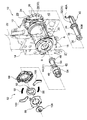
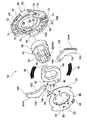
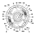
- FIG. 1 It is a disassembled perspective view which shows the structure of the clutch mechanism of the webbing take-up device concerning one embodiment of the present invention. It is a disassembled perspective view which shows the structure of the clutch mechanism of the webbing take-up device shown in FIG. It is the disassembled perspective view which looked at the clutch mechanism of the webbing take-up device shown in FIG. 1 from the side opposite to the spool. It is the front view which looked at the clutch mechanism of the webbing take-up device shown in FIGS. 2 and 3 from the side opposite to the spool. It is a figure which shows the state which the clutch plate of the clutch mechanism shown by FIG. 4 began to rotate to the lock ring side. It is a figure which shows the state which the clutch plate shown by FIG.
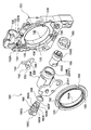
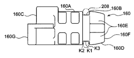
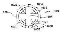
- FIG. 2 is an exploded perspective view showing a force limiter load switching mechanism of the webbing take-up device shown in FIG. 1. It is a perspective view which shows the state at the time of the assembly completion of the force limiter load switching mechanism shown by FIG. It is a left view which shows the piston part which comprises a part of force limiter load switching mechanism. It is a bottom view which shows the piston part which comprises a part of force limiter load switching mechanism. It is a right view which shows the piston part which comprises a part of force limiter load switching mechanism. It is a rear view which shows the piston part which comprises a part of force limiter load switching mechanism. It is a left view which shows the cylinder part which comprises a part of force limiter load switching mechanism.
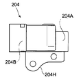
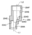
- FIG. 9B is a cross-sectional view showing a cross section of the cylinder section cut along line 9D-9D shown in FIG. 9B. It is an expanded sectional view which shows the piston part contact
- a webbing take-up device according to an embodiment of the present invention will be described with reference to FIGS.
- a webbing take-up device 10 includes a frame 12, a spool 20, a webbing 22, a lock gear 24 as a lock portion, and a force limiter mechanism 31.
- a torsion shaft 32, a trigger wire 40, a sub torsion shaft 44, and a clutch mechanism 52 are provided.
- the webbing take-up device 10 includes a force limiter load switching mechanism 120.
- the frame 12 will be described first, and then the spool 20, webbing 22, lock gear 24, main torsion shaft 32, trigger wire 40, sub torsion shaft 44, clutch mechanism 52, and force limiter load switching mechanism 120 will be described in this order.
- the frame 12 is formed in a substantially concave shape in a plan view and includes a plate-like back plate 14 fixed to the vehicle body. Further, leg pieces 16 and 18 are extended substantially at right angles from both ends in the width direction of the back plate 14. A known locking mechanism (not shown) is attached to the outside of the leg piece 18.
- the spool 20 is formed in a cylindrical shape having a through hole 21 penetrating in the axial direction, and is disposed between the leg piece 16 and the leg piece 18 of the frame 12.
- the spool 20 is disposed in a state where the axial direction is along the opposing direction of the leg piece 16 and the leg piece 18, and is rotatably supported by the frame 12 via a main torsion shaft 32, a sub torsion shaft 44 and the like which will be described later. ing.
- the webbing 22 is attached to the occupant's body, and a base end portion which is one end portion in the longitudinal direction is locked to the spool 20.
- the spool 20 is configured to take up and store the webbing 22 from the base end side by rotating in one winding direction, ie, the winding direction (the direction of arrow A in FIG. 1 and the like).
- the lock gear 24 is arranged coaxially with the spool 20 on one axial side of the spool 20.
- a gear portion 26 is formed on the outer peripheral portion of the lock gear 24.
- a through hole 28 penetrating in the axial direction is formed in the axial center portion of the lock gear 24, and a spline-like engaged portion 30 is formed in the inner peripheral portion of the through hole 28. .
- the lock gear 24 engages with a lock member (not shown) when the vehicle is suddenly decelerated and when the spool 20 is suddenly rotated in the pull-out direction.
- a lock member not shown
- the rotation of the lock gear 24 in the pull-out direction (the direction of arrow B in FIG. 1 and the like) is restricted (locked), and the rotation of the spool 20 in the pull-out direction is restricted.
- the main torsion shaft 32 is disposed coaxially with the spool 20 and the lock gear 24 and is inserted into the through hole 21 of the spool 20 and the through hole 28 of the lock gear 24, respectively.
- the main torsion shaft 32 is formed with a spline-shaped first engaging portion 34 at the center in the longitudinal direction, and a spline-shaped second engaging portion 36 is also formed at the tip.
- the main torsion shaft 32 is fixed to the lock gear 24 so as to be integrally rotatable by engaging the first engagement portion 34 with the engaged portion 30 of the lock gear 24.
- the main torsion shaft 32 can rotate integrally with the spool 20 by the second engaging portion 36 being engaged with an engaged portion (not shown) formed in the axially intermediate portion of the inner peripheral portion of the spool 20. It is fixed to. A portion of the main torsion shaft 32 between the first engaging portion 34 and the second engaging portion 36 absorbs the kinetic energy of the occupant used for pulling the webbing 22 as will be described later.
- the unit 38 is configured.
- the base end portion 40A of the trigger wire 40 is inserted into a hole 29 formed at a position radially outward from the through hole 28 in the lock gear 24 and is locked to the lock gear 24.
- the distal end side of the trigger wire 40 from the proximal end portion 40A is inserted into a hole portion 42 formed in the spool 20 in parallel with the through hole 21, and the distal end portion 40B extends from the spool 20 to the other side in the axial direction. Is protruding.
- the sub torsion shaft 44 is arranged coaxially with the main torsion shaft 32, and the base end side is inserted into the through hole 21 of the spool 20 from the center in the longitudinal direction. On the other hand, the tip side of the sub torsion shaft 44 from the longitudinal center is projected from the spool 20 to the other side in the axial direction.
- the sub-torsion shaft 44 has a first engagement portion 46 that is at least partially spline-shaped at the base end portion, and a second engagement portion 48 that is also spline-shaped at the distal end portion. Has been.
- first engaging portion 46 is engaged with an engaged portion (not shown) formed in an intermediate portion in the axial direction in the inner peripheral portion of the spool 20, whereby the sub torsion shaft 44 is engaged with the spool 20. It is fixed so that it can rotate together. Further, a portion between the first engagement portion 46 and the second engagement portion 48 of the sub torsion shaft 44 is a second portion for absorbing the kinetic energy of the occupant used for pulling the webbing 22 as will be described later.
- the energy absorbing unit 50 is configured.
- the clutch mechanism 52 includes a sleeve 54, a clutch guide 64, a clutch base 82, a clutch cover 88, a pair of clutch plates 100, a screw 108, and a pair of coil springs. 98.
- FIG. 5A shows a state during the operation of the clutch mechanism 52
- FIG. 5B shows a state where the operation of the clutch mechanism 52 is completed.
- the sleeve 54 is arranged coaxially with the sub-torsion shaft 44.
- a through hole 56 penetrating in the axial direction is formed in the axial center portion of the sleeve 54, and the sub torsion shaft 44 is loosely inserted into the through hole 56.
- a spline-like engaged portion 58 is formed on the distal end side of the inner peripheral portion of the sleeve 54.
- the sleeve 54 is fixed to the sub torsion shaft 44 so as to be integrally rotatable by engaging the second engaging portion 48 (see FIG. 3) of the sub torsion shaft 44 with the engaged portion 58.
- the proximal end side of the sleeve 54 is a support portion 60 having a circular outer shape, and the distal end side of the sleeve 54 is a fitting portion 62 having a hexagonal outer shape. ing.
- the clutch guide 64 is made of resin and is formed in an annular shape having a through hole 66 penetrating in the axial direction.
- the above-described support portion 60 is inserted into the through-hole 66, whereby the clutch guide 64 is supported by the sleeve 54 so as to be relatively rotatable.
- a pair of coil spring accommodating portions 68 for accommodating the coil springs 98 are formed at two positions in the circumferential direction of the clutch guide 64.
- the coil spring accommodating portions 68 are arranged symmetrically with respect to the center portion of the clutch guide 64, and each of the outer wall portion 70 and the inner wall portion 72 extending in the circumferential direction of the clutch guide 64, the clutch
- the guide 64 is formed in a substantially J shape having a connecting wall portion 74 that extends in the radial direction and connects the outer wall portion 70 and each end portion of the inner wall portion 72.
- the outer wall portion 70 is formed with a long hole-shaped guide hole 70A whose longitudinal direction is the circumferential direction.
- the clutch guide 64 is formed with a pair of clutch plate accommodating portions 76 for accommodating the clutch plate 100 adjacent to the coil spring accommodating portions 68.
- These clutch plate housing portions 76 include a first support wall portion 78 extending from the connecting wall portion 74 toward the opposite side to the inner wall portion 72, and a connecting wall on the opposite side of the outer wall portion 70 with respect to the connecting wall portion 74.
- a second support wall portion 80 is erected apart from the portion 74.
- the clutch base 82 is configured to have an annular mated portion 84.
- a fitting portion 62 of the sleeve 54 is fitted (press-fitted) inside the fitted portion 84, whereby the clutch base 82 is fixed to the sleeve 54 so as to be integrally rotatable.
- the sleeve 54 and the clutch base 82 may be integrally formed.
- the clutch base 82 is formed with a pair of locking portions 86 protruding outward from the fitted portion 84. These locking portions 86 are locked to a base end portion of an arm portion 102 formed on a clutch plate 100 described later.
- the clutch cover 88 is disposed coaxially with the sleeve 54, is disposed on the opposite side of the spool 20 with respect to the clutch guide 64, and is disposed opposite to the clutch guide 64.
- the clutch cover 88 is formed in an annular shape having a through hole 90 penetrating in the axial direction, and a plurality of fitting claws 92 projecting radially inward are formed on the inner peripheral portion thereof. Then, the fitting portion 62 of the sleeve 54 is inserted into the through hole 90 and the plurality of fitting claws 92 are fitted to the fitting portion 62, so that the clutch cover 88 is connected to the sleeve 54, and thus the subtorsion. It is fixed to the shaft 44 so as to be integrally rotatable.
- a pair of spring locking claws 94 are provided at two positions in the circumferential direction of the clutch cover 88, and the pair of spring locking claws 94 are centered on the center of the clutch cover 88. Are arranged symmetrically.
- One end of a coil spring 98 disposed in the coil spring accommodating portion 68 of the clutch guide 64 is locked to the pair of spring locking claw portions 94.
- a guide claw portion 96 is provided on the outer peripheral portion of the one spring locking claw portion 94.
- the guide claw portion 96 is disposed in the guide hole 70A provided in the clutch guide 64 and is moved along the guide hole 70A, whereby the clutch guide 64 is moved relative to the clutch cover 88. Relative rotation is enabled between the operating position shown in FIG. 5B and the non-operating position shown in FIG.
- the clutch plate 100 is disposed between the clutch cover 88 and the clutch guide 64.
- the clutch plate 100 has an arm portion 102 and a circular arc portion 104 formed at the distal end portion of the arm portion 102.
- a rotation shaft 106 that protrudes toward the clutch cover 88 and extends along the axial direction of the sub-torsion shaft 44 is formed at the base end portion of the arm portion 102.
- the clutch plate 100 is rotatably supported by the clutch cover 88 by inserting the rotation shaft 106 into a hole 89 formed in the clutch cover 88.
- spur-shaped knurled teeth 104A are formed on the outer peripheral portion of the arc portion 104 (the tip portion of the clutch plate 100).
- the screw 108 includes a screw portion 110 and a presser portion 112 having a larger diameter than the screw portion 110.
- the screw portion 110 is screwed into a screw hole 45 (see FIG. 1) formed at the tip portion of the sub torsion shaft 44, whereby the screw 108 is fixed to the tip portion of the sub torsion shaft 44. .
- the presser portion 112 is brought into contact with the distal end portion of the sleeve 54.
- the clutch guide 64 is restricted from moving in the axial direction by the clutch cover 88 and the spool 20.
- holes 65 and 91 are formed in the above-described clutch guide 64 and clutch cover 88, respectively. These holes 65 and 91 are formed so as to face each other in a state where the clutch guide 64 is disposed at the non-operating position with respect to the clutch cover 88, and the trigger wire 40 is formed in these holes 65 and 91. Each tip 40B (see FIG. 1) is inserted. Thereby, the clutch guide 64 is restricted in relative rotation with respect to the spool 20 and the clutch cover 88 in a state where the clutch guide 64 is disposed at the non-operating position (the clutch guide 64 is restrained at the non-operating position).
- the coil spring 98 is connected to the coil spring accommodating portion 68 (connection wall portion 74) of the clutch guide 64 and the spring engaging claw portion of the clutch cover 88. 94 is compressed.
- the force limiter load switching mechanism 120 includes a body 122 formed in a box shape, a gas generator 194 as a gas generator, and the pressure of the gas generated by the gas generator 194.
- operates and the cylinder part 204 which accommodates a part of piston part 160 inside are provided.
- the force limiter load switching mechanism 120 includes a pawl 150 serving as a switching member that is displaced by being pressed by the piston portion 160, a lock ring 190 whose rotation is restricted by this pawl 150 or this restriction is released, It has.
- the body 122 is formed using a resin material and is formed so as to open to the leg piece 16 side of the frame 12 (see FIG. 1). Specifically, the body 122 includes a pawl 150 (to be described later), a first accommodating portion 124 in which a part of the piston portion 160 is accommodated, and a second accommodating portion 125 in which the lock ring 190 is accommodated.
- a housing groove 130 for movably housing the piston portion 160 is formed so as to open to the leg piece 16 side of the frame 12 (see FIG. 1). Furthermore, the pawl 150 is accommodated in the first accommodating portion 124, and a recess 132 connected to the accommodating groove 130 is formed so as to open to the leg piece 16 side (see FIG. 1) of the frame 12. Yes. Further, a shaft support portion 132A that rotatably supports the shaft portion 152 of the pawl 150 is erected in the recessed portion 132, and a shear pin 132B that restricts rotation around the support portion 132A of the pawl 150 is erected.
- a recess 138 in which the lock ring 190 is housed is formed so as to open to the leg piece 16 side of the frame 12 (see FIG. 1).
- the recess 138 is formed with a circular opening 140 that is concentric with the axis of the spool 20 (see FIG. 1).
- the second receiving portion 125 includes three lock ring engaging claws 139 that restrict the movement of the lock ring 190 toward the leg piece 16 side by engaging with the lock ring 190 disposed in the recess 138. Is provided.
- the body 122 described above is fixed to the outside of the leg piece 16 (see FIG. 1).
- the gas generator 194 is formed in a substantially cylindrical shape, and one end portion is a gas ejection portion 194A from which gas is ejected, and the other end portion is a wiring connection portion 194B to which wiring is connected.
- the gas generator 194 is inserted into a second cylindrical portion 204B of the cylinder portion 204 described later from the gas ejection portion 194A side, and is fixed to the cylinder portion 204 using a fixing member 195.
- the pawl 150 is formed in a block shape using a metal material, and has a shaft portion 152 having a substantially circular cross section, and an arm portion 154 formed to extend outward in the radial direction of the shaft portion 152. And an engaging portion 156.
- the shaft portion 152 is rotatably supported by a shaft support portion 132A provided in the first housing portion 124 of the body 122.
- the pawl 150 is formed with a locking hole 158 having a circular cross section.
- the shear pin 132B provided in the first housing portion 124 of the body 122 is inserted into the locking hole 158 so that the rotation of the pawl 150 around the support portion 132A is restricted.
- the engaging portion 156 is engaged with a notch 192 of the lock ring 190 described later.
- the position of the pawl 150 in this state is referred to as a “lock position”.
- the arm portion 154 is arranged close to a pressing portion 160C of the piston portion 160 described later.
- the lock ring 190 is formed in a substantially annular shape using a metal material, and the lock ring 190 is disposed coaxially with the clutch mechanism 52 on the outer peripheral side of the clutch mechanism 52.
- spur-shaped knurled teeth 190 ⁇ / b> A are formed on the inner peripheral portion of the lock ring 190.
- a cutout portion 192 having a substantially triangular cross section is formed on the outer peripheral portion of the lock ring 190, and the cutout portion 192 is opened outward in the radial direction of the lock ring 190.
- three engaged recesses 193 whose edges are substantially U-shaped are formed on the outer peripheral portion of the lock ring 190, and the engaged recesses 193 are opened outward in the radial direction of the lock ring 190.
- the three engaged recesses 193 are arranged at intervals in the circumferential direction of the lock ring 190.
- the three lock ring engaging claws 139 provided in the second accommodating portion 125 of the body 122 are respectively engaged with the three engaged recesses 193, whereby the leg pieces 16 of the lock ring 190 (FIG. 1). Reference) movement to the side is regulated.
- the lock ring 190 demonstrated above is rotatably supported with respect to the said body 122 in the state accommodated in the recessed part 138 formed in the 2nd accommodating part 125 of the body 122.
- the piston portion 160 is formed using a resin material, and the proximal end side of the piston portion 160 is formed in a substantially columnar shape, and a cylinder portion 204 described later.
- the insertion portion 160A is inserted into the first cylindrical portion 204A.
- an O-ring mounting groove 160B as a concave groove is formed along the circumferential direction on the outer peripheral portion of the intermediate portion in the axial direction of the insertion portion 160A.
- the O-ring mounting groove 160B has a bottom wall K1 and a pair of side walls K2 and K3, thereby forming a concave shape in which the radially outer side of the insertion portion 160A is opened.
- An O-ring 208 as a seal member formed using a material having viscoelasticity such as rubber is disposed in a region surrounded by the bottom wall K1 and the pair of side walls K2, K3 of the O-ring mounting groove 160B. Thus, the O-ring 208 is attached to the piston portion 160.
- the O-ring 208 prevents the gas generated by the gas generator 194 from leaking between the insertion portion 160A and a first cylindrical portion 204A described later.
- a narrowed portion 160D is formed so as to gradually narrow toward the side opposite to the pressing portion 160C.
- the narrowed portion 160D is formed with four V-shaped grooves 160E as communication portions whose edges are substantially V-shaped, and one end of the V-shaped groove 160E is an O-ring mounting groove 160B. It is connected to the. In other words, as shown in FIG.
- the O-ring 208 and the side wall K3 of the O-ring mounting groove 160B do not overlap each other at the site where the V-shaped groove 160E is formed when the insertion portion 160A is viewed from the base end side. It is like that.
- the end surface of the narrowed portion 160D opposite to the pressing portion 160C is a contact portion 160F that contacts a contacted portion 204E provided in a first cylindrical portion 204A described later.
- a pressing portion 160C for pressing the arm portion 154 (see FIG. 6) of the pawl 150 is provided on the distal end side of the piston portion 160. Furthermore, a guide block portion 160G that is disposed in the accommodation groove 130 (see FIG. 6) provided in the first accommodation portion 124 of the body 122 and moves along the accommodation groove 130 at the distal end side of the piston portion 160. Is provided adjacent to the pressing portion 160C.
- the cylinder portion 204 is formed using a metal material. Specifically, the cylinder portion 204 is formed in a cylindrical shape, and the first cylindrical portion 204A into which the insertion portion 160A (see FIGS. 8A to 8D) of the piston portion 160 is inserted, and the first cylindrical portion 204A. And a second cylindrical portion 204B that is communicated with the cylindrical portion 204A and into which the gas of the gas generator 194 is supplied.
- the inner peripheral surface of the first cylindrical portion 204A is formed in a cylindrical surface shape corresponding to the shape of the O-ring 208 described above.
- a portion 204C on the second tubular portion 204B side of the first tubular portion 204A overlaps a portion 204D on the first tubular portion 204A side in the second tubular portion 204B in the radial direction.
- the central axis L2 of the second cylindrical portion 204B is arranged offset in the radial direction of the first cylindrical portion 204A with respect to the central axis L1 of the first cylindrical portion 204A.
- the gas path in the cylinder part 204 from the second cylindrical part 204B to the first cylindrical part 204A is bent in a crank shape.
- the boundary between the first cylindrical portion 204A and the second cylindrical portion 204B that is, in the first cylindrical portion 204A.
- An abutted portion 204E with which the abutting portion 160F of the piston portion 160 abuts is formed at the end portion on the second cylindrical portion 204B side.
- the state in which the contact portion 160F of the piston portion 160 is in contact with the contacted portion 204E is set to be a state where the assembly of the piston portion 160 to the cylinder portion 204 is completed. Has been.
- the end of the second cylindrical portion 204B opposite to the first cylindrical portion 204A is an engaged portion 204F to which the gas generator 194 is engaged.
- two step portions 204G are formed in the second cylindrical portion 204B at a site closer to the first cylindrical portion 204A than the engaged portion 204F.
- the flow path area of the 2nd cylindrical part 204B is set so that it may become narrow as it goes to the 1st cylindrical part 204A side.
- the cylinder portion 204 includes a fixed flange portion 204H formed in a tongue shape.
- the cylinder portion 204 is attached to the body 122 by fixing the flange portion 204 ⁇ / b> H to the body 122.
- the spool 20, the lock gear 24, the main torsion shaft 32, the sub torsion shaft 44, and the clutch mechanism 52 are configured to be integrally rotatable in the winding direction and the drawing direction. Therefore, the webbing 22 is pulled out from the spool 20 so that the webbing 22 is attached to the body of the vehicle occupant.
- the lock gear 24 is prevented from rotating in the pull-out direction.
- the occupant's body pulls the webbing 22 with a larger force, and the rotation force of the spool 20 in the pull-out direction based on this pulling force is applied to the main torsion shaft 32.
- the force limiter mechanism 31 is operated, and the force limiter load (first force) of the spool 20 due to the torsion (deformation) of the first energy absorbing portion 38. Rotation in the pull-out direction above the torsional load) of the energy absorbing portion 38 is allowed.
- the spool 20 is rotated in the pull-out direction by the twist of the first energy absorbing portion 38 and the webbing 22 is pulled out from the spool 20, thereby reducing the load (burden) on the chest of the occupant by the webbing 22. Further, the kinetic energy of the occupant used for pulling the webbing 22 is absorbed by the twist of the first energy absorbing portion 38.
- the fact that the spool 20 is rotated in the pull-out direction with respect to the lock gear 24 means that the lock gear 24 is rotated in the winding direction relative to the spool 20. Therefore, when the lock gear 24 is rotated relative to the spool 20 in the winding direction, the proximal end portion of the trigger wire 40 is kept inserted in the hole portion 42 of the spool 20 with the distal end side being inserted into the hole portion 42 of the spool 20. Since 40A is moved in the circumferential direction of the main torsion shaft 32, the distal end side of the trigger wire 40 is pulled toward the lock gear 24 with respect to the hole portion 42 rather than the base end portion 40A.
- the distal end portion 40B of the trigger wire 40 is pulled out from the hole portion 65 of the clutch guide 64 and the hole portion 91 of the clutch cover 88, and the state where the relative rotation of the clutch guide 64 with respect to the spool 20 and the clutch cover 88 is prevented. .
- the control device determines whether or not the occupant's physique is greater than or equal to a predetermined reference value based on the signal from the physique detection means, and based on the signal from the collision detection means, the vehicle It is determined whether or not.
- the gas generator 194 shown in FIGS. 6 and 7 is not operated, so that the engaging portion 156 of the pawl 150 is
- the lock ring 190 is disposed at the lock position and is engaged with the notch 192 of the lock ring 190. Therefore, the rotation of the lock ring 190 in the pull-out direction is locked (blocked), so that the clutch mechanism 52 (the sleeve 54, the clutch base 82, and the clutch plate 100) is blocked from rotating in the pull-out direction.
- the occupant's body pulls the webbing 22 with a larger force in a state where the rotation of the sleeve 54 in the pull-out direction is prevented, and the spool 20 is pulled in the pull-out direction based on this pulling force.
- the rotational force exceeds the sum of the torsion resistant load (deformation resistant load) of the first energy absorbing portion 38 of the main torsion shaft 32 and the torsion resistant load (deformation resistant load) of the second energy absorbing portion 50 of the sub torsion shaft 44.
- the force limiter load of the spool 20 (the torsion resistant load of the first energy absorbing portion 38 and the torsion resistant load of the second energy absorbing portion 50) due to the twist (deformation) of the first energy absorbing portion 38 and the second energy absorbing portion 50. Rotation in the pull-out direction above is allowed.
- the spool 20 is rotated in the pull-out direction due to the twisting of the first energy absorbing portion 38 and the second energy absorbing portion 50 and the webbing 22 is pulled out from the spool 20. ) Is reduced, and the kinetic energy of the occupant used to pull the webbing 22 is absorbed by the amount of twist of the first energy absorbing portion 38 and the second energy absorbing portion 50.
- control device determines that the occupant's physique is less than a predetermined reference value based on the signal from the physique detection means, and determines that the vehicle has collided based on the signal from the collision detection means.
- the gas generator 194 shown in FIGS. 6 and 7 is operated under the control of the control device.
- the gas ejected from the gas ejection part 194A of the gas generator 194 is supplied into the second cylindrical part 204B of the cylinder part 204, and the second cylindrical part 204B and the second cylinder are supplied.
- the pressure in the first cylindrical portion 204A communicated with the cylindrical portion 204B increases.
- the piston part 160 provided in the first cylindrical part 204A is moved along the first cylindrical part 204A.
- the pressed portion 160C of the moved piston portion 160 presses the arm portion 154 of the pawl 150.
- the shear pin 132B inserted through the locking hole 158 of the pawl 150 is sheared, and the pawl 150 is rotated about the shaft support portion 132A.
- the engagement between the engagement portion 156 of the pawl 150 and the cutout portion 192 of the lock ring 190 is released (the position of the pawl 150 in this state is referred to as “release position”).
- release position the position of the pawl 150 in this state is referred to as “release position”.
- the force limiter load is the sum of the torsional load of the first energy absorbing unit 38 and the torsional load of the second energy absorbing unit 50, The load value of the force limiter load is increased.
- the force limiter load is changed to the torsion resistant load of the first energy absorbing portion 38, and the load of the force limiter load is set. The value is lowered. For this reason, a passenger
- the state in which the contact portion 160 ⁇ / b> F of the piston portion 160 is in contact with the contacted portion 204 ⁇ / b> E provided in the cylinder portion 204 is the cylinder of the piston portion 160. It is set so that the assembly to the unit 204 is completed. With this setting, the volume of the space between the piston part 160 and the gas generator 194 in the cylinder part 204 is stabilized, and the pressure rise characteristic in the cylinder part 204 when the gas generator 194 is operated is stabilized. be able to. Thereby, the operating force of the piston part 160 (the load input to the pawl 150 from the piston part 160) can be stabilized.
- the volume of the space between the piston portion 160 and the gas generator 194 in the cylinder portion 204 does not vary excessively, so that the output of the gas generator 194 is taken into account the excessive volume variation. Does not have to be set. That is, the output of the gas generator 194 may not be increased in consideration of the excessive volume variation. Thereby, the enlargement of the physique of the gas generator 194 can be suppressed, and as a result, the increase in the physique of the force limiter load switching mechanism 120 can be suppressed.
- the base portion side portion of the insertion portion 160A of the piston portion 160 is gradually narrowed toward the opposite side of the pressing portion 160C from the portion where the O-ring mounting groove 160B is formed.
- the narrowed portion 160D is formed.
- the O-ring 208 is fitted into the O-ring 208 through the four V-shaped grooves 160E formed in the constricted portion 160D for the gas of the gas generator 194 flowing into the first cylindrical portion 204A from the second cylindrical portion 204B. It can flow quickly into the mounting groove 160B, and the pressure increase speed around the O-ring 208 can be increased. As a result, when the gas generator 194 is operated, the O-ring 208 can be quickly deformed (the O-ring 208 can be deformed so as to be crushed in the axial direction of the insertion portion 160A of the piston portion 160). The gas sealing performance by 208 can be enhanced.
- the flow passage area of the second cylindrical portion 204B to which the gas of the gas generator 194 is supplied is set so as to become narrower toward the first cylindrical portion 204A.
- the gas from the gas generator 194 can be quickly passed through the first cylindrical portion 204A.
- the example in which the flow passage area of the second tubular portion 204B to which the gas of the gas generator 194 is supplied is set to become narrower toward the first tubular portion 204A side has been described.
- the invention is not limited to this. Whether or not to set the flow path area of the second cylindrical portion 204B as described above is appropriately set in consideration of the volume of the space between the piston portion 160 and the gas generator 194 in the cylinder portion 204. That's fine.
- constricted portion 160D is provided in the piston portion 160 and the V-shaped groove 160E is provided in the constricted portion 160D has been described, but the present invention is not limited to this. Whether or not the constricted portion 160D and the V-shaped groove 160E are provided in the piston portion 160 may be appropriately set in consideration of the sealing property of the O-ring 208 and the like.
- the guide claw portion 96 of the clutch cover 88 is disposed in the guide hole 70A provided in the clutch guide 64 and along the guide hole 70A.
- the clutch guide 64 is rotatable relative to the clutch cover 88 between the operating position shown in FIG. 5B and the non-operating position shown in FIG.
- the tip 40B (see FIG. 1) of the trigger wire 40 is inserted into the holes 65 and 91 (see FIG. 1) formed in the clutch guide 64 and the clutch cover 88, respectively. (Trigger wire insertion step). Thereby, the clutch guide 64 is restrained in the non-operation position.
- the clutch mechanism 52 with the clutch guide 64 positioned at the non-actuated position is carried into a production line for performing the trigger wire insertion process.
- a locking portion in which the guide claw portion 96 of the clutch cover 88 is locked to a part of the guide hole 70 ⁇ / b> A provided in the clutch guide 64. 70B is provided. Then, the guide claw portion 96 of the clutch cover 88 is locked to the locking portion 70B, so that the state where the clutch guide 64 is disposed at the non-actuated position is maintained. Note that, after the trigger wire insertion step, the guide claw portion 96 may be moved to release the engagement between the guide claw portion 96 and the locking portion 70B.
- the workability of the trigger wire insertion process can be improved.
Landscapes
- Engineering & Computer Science (AREA)
- Mechanical Engineering (AREA)
- Automotive Seat Belt Assembly (AREA)
Abstract
ウェビング巻取装置は、スプールと、スプールの引出方向への回転を規制するロックギヤと、スプールのフォースリミッタ荷重以上での引出方向への回転を許容するフォースリミッタ機構と、フォースリミッタ荷重を切替えるパウルと、を備える。ウェビング巻取装置は、第1筒状部(204A)及び第2筒状部(204B)を有するシリンダ部(204)と、第2筒状部(204B)内にガスを供給するガスジェネレータと、第2筒状部(204B)及び第1筒状部(204A)内の圧力が上昇することで、第1筒状部(204A)に沿って移動されて、パウルを押圧して変位させるピストン部(160)とを備える。第2筒状部(204B)の中心軸は、第1筒状部の中心軸に対してオフセットして配置され、第1筒状部(204A)と第2筒状部(204B)との境界部には、ピストン部(160)が当接される被当接部(204E)が設けられる。
Description
本発明は、スプールの引出方向への回転をロック部が規制した際に、スプールがフォースリミッタ荷重以上で引出方向への回転することを許容するウェビング巻取装置に関する。
特表2003-502204号公報には、駆動装置が作動されることでフォースリミッタ荷重が切替えられるウェビング巻取装置が開示されている。このウェビング巻取装置の一部を構成する駆動装置は、筒状に形成されたシリンダ部と、当該シリンダ部の一方側の端部に取付けられたガスジェネレータと、シリンダ部内に配置されたピストン部と、を含んで構成されている。そして、ガスジェネレータが発生したガスの圧力によりピストン部がシリンダ部内を移動して、当該ピストン部が操作リングの段部を押圧することで、フォースリミッタ荷重が切替えられるようになっている。
しかしながら、ガスジェネレータのガスが充填されるシリンダ部内の初期の容量(作動される前のガスジェネレータとピストン部との間の空間の容積)が安定しないと、ピストン部の作動力が安定しないことが考えられる。
本発明は上記事実を考慮し、ピストン部の作動力を安定させることができるウェビング巻取り装置を得ることが目的である。
本発明の第1の態様のウェビング巻取装置は、乗員に装着されるウェビングが巻取られ、前記ウェビングが引出されることで引出方向へ回転されるスプールと、車両の緊急時に前記スプールの引出方向への回転を規制するロック部と、前記ロック部が前記スプールの引出方向への回転を規制した際に前記スプールのフォースリミッタ荷重以上での引出方向への回転を許容するフォースリミッタ機構と、変位されることで前記フォースリミッタ荷重を切替える切替部材と、筒状に形成された第1筒状部と、中心軸が前記第1筒状部の中心軸に対してオフセットして配置されていると共に前記第1筒状部に連通された第2筒状部と、前記第1筒状部と前記第2筒状部との境界部に設けられた被当接部と、を有するシリンダ部と、作動されて前記第2筒状部内にガスを供給するガス発生装置と、前記被当接部に当接された状態で前記第1筒状部内に配置されており、前記ガス発生装置が作動されて前記第2筒状部内及び前記第1筒状部内の圧力が上昇することで、前記第1筒状部に沿って移動されて、前記切替部材を押圧して変位させるピストン部と、を備えている。
本発明の第2の態様のウェビング巻取装置は、第1の態様のウェビング巻取装置において、 前記ピストン部の外周部には、該ピストン部と前記第1筒状部との間をシールすると共に弾性を有する材料を用いて形成されたシール部材が取付けられており、前記ピストン部において前記シール部材が取付けられた部分よりも前記被当接部側の部位が窄まっている。
本発明の第3の態様のウェビング巻取装置は、第1又は第2の態様のウェビング巻取装置において、前記ピストン部の外周部には、該ピストン部と前記第1筒状部との間をシールすると共に弾性を有する材料を用いて形成されたシール部材が嵌まり込む凹溝が形成されており、前記ピストン部において前記凹溝が形成された部位よりも前記被当接部側には、前記凹溝と連通されていると共に前記ガス発生装置のガスが通過する連通部が設けられている。
本発明の第1の態様のウェビング巻取装置では、乗員に装着されるウェビングがスプールに巻取られており、このウェビングがスプールから引出されることで、当該ウェビングが乗員に装着されるようになっている。また、車両の緊急時には、スプールの引出方向への回転がロック部によりロックされる。この状態で、ウェビングが引出される方向へ引張られて、スプールに作用する荷重がフォースリミッタ荷重以上となると、スプールの引出方向への回転が許容される。
また、本発明のウェビング巻取装置では、ガス発生装置が作動されて、当該ガス発生装置が発生したガスがピストン部の第2筒状部内に供給されると、第2筒状部内及び当該第2筒状部と連通された第1筒状部内の圧力が高まる。これにより、第1筒状部内に設けられたピストン部が、第1筒状部内に沿って移動される。そして、移動されたピストン部が切替部材を押圧して変位させることで、フォースリミッタ荷重が切替えられる。
ここで、本発明のウェビング巻取装置では、ピストン部が、シリンダ部における第1筒状部と第2筒状部との境界部に設けられた被当接部に当接された状態で当該第1筒状部内に配置されている。当該配置とすることにより、シリンダ部内におけるピストン部とガス発生装置との間の空間の容積が安定し、ガス発生装置が作動された際のシリンダ部内の圧力上昇特性が安定する。これにより、ピストン部の作動力を安定させることができる。
本発明の第2の態様のウェビング巻取装置では、ピストン部においてシール部材が取付けられた部分よりもシリンダ部の被当接部側の部位が、当該被当接部側に向かうにつれて窄まるように形成されている。これにより、第2筒状部から第1筒状部内に流れ込んだガス発生装置のガスをシール部材側に向けて速やかに流すことができ、シール部材周辺の圧力上昇速度を速めることができる。その結果、ガス発生装置が作動された際に、シール部材を速やかに変形させることが可能となり、シール部材によるガスのシール性を高めることができる。
本発明の第3の態様のウェビング巻取装置では、第2筒状部内から第1筒状部内に流れ込んだガス発生装置のガスをピストン部に設けられた連通部を通じてシール部材が嵌まり込む凹溝内に速やかに流すことができる。これにより、シール部材周辺の圧力上昇速度を速めることができる。その結果、ガス発生装置が作動された際に、シール部材を速やかに変形させることが可能となり、シール部材によるガスのシール性を高めることができる。
図1~図12を用いて、本発明の実施形態に係るウェビング巻取装置について説明する。
図1に示されるように、本発明の実施形態に係るウェビング巻取装置10は、フレーム12と、スプール20と、ウェビング22と、ロック部としてのロックギヤ24と、フォースリミッタ機構31を構成するメイントーションシャフト32、トリガワイヤ40、サブトーションシャフト44及びクラッチ機構52と、を備えている。また、図6に示されるように、ウェビング巻取装置10は、フォースリミッタ荷重切替機構120を備えている。以下、先ずフレーム12について説明し、次いでスプール20、ウェビング22、ロックギヤ24、メイントーションシャフト32、トリガワイヤ40、サブトーションシャフト44、クラッチ機構52及びフォースリミッタ荷重切替機構120についてこの順で説明する。
図1に示されるように、フレーム12は、平面視で略凹形状に形成されていると共に、車体に固定される板状の背板14を備えている。また、背板14の幅方向両端部からは脚片16,18が略直角に延出されている。なお、脚片18の外側には、周知のロック機構(図示省略)が取付けられている。
スプール20は、軸方向に貫通する貫通孔21を有する円筒状に形成されており、フレーム12の脚片16と脚片18との間に配置されている。スプール20は、軸線方向が脚片16と脚片18との対向方向に沿う状態で配置されており、後述するメイントーションシャフト32、サブトーションシャフト44等を介してフレーム12に回転可能に支持されている。
ウェビング22は、乗員の身体に装着されるものであり、その長手方向一端部である基端部がスプール20に係止されている。スプール20は、一方の回転方向である巻取方向(図1等の矢印Aの方向)へ回転することでウェビング22を基端側から巻取って収納する構成となっている。
ロックギヤ24は、スプール20の軸方向一方側にスプール20と同軸上に配置されている。このロックギヤ24の外周部にはギヤ部26が形成されている。また、このロックギヤ24の軸心部には、軸方向に貫通する貫通孔28が形成されており、当該貫通孔28の内周部には、スプライン状の被係合部30が形成されている。
ロックギヤ24は、車両の急減速時及びスプール20が急激に引出方向へ回転した際に、ロック部材(図示省略)と係合する。その結果、ロックギヤ24の引出方向(図1等の矢印Bの方向)への回転が規制(ロック)され、スプール20の引出方向への回転が規制される。
メイントーションシャフト32は、スプール20及びロックギヤ24と同軸上に配置されていると共に、スプール20の貫通孔21及びロックギヤ24の貫通孔28にそれぞれ挿入されている。このメイントーションシャフト32には、その長手方向中央部にスプライン状の第一係合部34が形成されると共に、その先端部に同じくスプライン状の第二係合部36が形成されている。そして、この第一係合部34がロックギヤ24の被係合部30と係合されることにより、メイントーションシャフト32は、ロックギヤ24に一体回転可能に固定されている。また、第二係合部36が、スプール20の内周部における軸線方向中間部に形成された図示しない被係合部と係合されることにより、メイントーションシャフト32がスプール20に一体回転可能に固定されている。このメイントーションシャフト32における第一係合部34と第二係合部36との間の部分は、後述する如くウェビング22の引張りに供される乗員の運動エネルギを吸収するための第一エネルギ吸収部38として構成されている。
トリガワイヤ40の基端部40Aは、ロックギヤ24における貫通孔28よりも径方向外側の位置に形成された孔部29に挿入されて、ロックギヤ24に係止されている。一方、トリガワイヤ40における基端部40Aよりも先端側は、貫通孔21と並行してスプール20に形成された孔部42に挿入されており、その先端部40Bは、スプール20から軸方向他方側に突出されている。
サブトーションシャフト44は、メイントーションシャフト32と同軸上に配置されており、その長手方向中央部よりも基端側は、スプール20の貫通孔21に挿入されている。一方、このサブトーションシャフト44の長手方向中央部よりも先端側は、スプール20から軸方向他方側に突出されている。このサブトーションシャフト44には、その基端部に少なくとも一部がスプライン状の第一係合部46が形成されると共に、その先端部には、同じくスプライン状の第二係合部48が形成されている。また、第一係合部46は、スプール20の内周部における軸線方向中間部に形成された図示しない被係合部と係合されており、これにより、サブトーションシャフト44は、スプール20に一体回転可能に固定されている。さらに、このサブトーションシャフト44における第一係合部46と第二係合部48との間の部分は、後述する如くウェビング22の引張りに供される乗員の運動エネルギを吸収するための第二エネルギ吸収部50として構成されている。
図2及び図3に示されるように、クラッチ機構52は、スリーブ54と、クラッチガイド64と、クラッチベース82と、クラッチカバー88と、一対のクラッチプレート100と、スクリュー108と、一対のコイルスプリング98とを備えている。なお、図5Aには、このクラッチ機構52の作動途中の状態が示されており、図5Bには、このクラッチ機構52の作動が完了した状態が示されている。
図3に示されるように、スリーブ54は、サブトーションシャフト44と同軸上に配置されている。このスリーブ54の軸心部には、軸方向に貫通する貫通孔56が形成されており、この貫通孔56には、上述のサブトーションシャフト44が遊挿されている。また図2に示されるように、このスリーブ54の内周部における先端側には、スプライン状の被係合部58が形成されている。そして、この被係合部58にサブトーションシャフト44の第二係合部48(図3参照)が係合されることにより、スリーブ54は、サブトーションシャフト44に一体回転可能に固定されている。また、このスリーブ54における基端側は、円形状の外形を有する支持部60とされており、このスリーブ54における支持部60よりも先端側は、六角形状の外形を有する嵌合部62とされている。
クラッチガイド64は、樹脂製とされており、軸方向に貫通する貫通孔66を有する環状に形成されている。この貫通孔66には、上述の支持部60が挿入されており、これにより、クラッチガイド64は、スリーブ54に相対回転可能に支持されている。このクラッチガイド64における周方向の二箇所の位置には、コイルスプリング98を収容する一対のコイルスプリング収容部68が形成されている。これらのコイルスプリング収容部68は、クラッチガイド64の中央部を中心とする点対称状に配置されており、それぞれ、クラッチガイド64の周方向に延びる外側壁部70及び内側壁部72と、クラッチガイド64の径方向に延びて外側壁部70と内側壁部72の各端部を連結する連結壁部74とを有する略J字形状に形成されている。また、外側壁部70には、周方向を長手方向とする長孔状のガイド孔70Aが形成されている。
また、このクラッチガイド64には、クラッチプレート100を収容する一対のクラッチプレート収容部76が各コイルスプリング収容部68に隣接して形成されている。これらのクラッチプレート収容部76には、連結壁部74から内側壁部72と反対側に向けて延びる第一支持壁部78と、連結壁部74に対する外側壁部70とは反対側に連結壁部74と離間して第二支持壁部80と、が立設されている。
クラッチベース82は、環状の被嵌合部84を有して構成されている。この被嵌合部84の内側には、スリーブ54の嵌合部62が嵌合(圧入)されており、これにより、クラッチベース82は、スリーブ54に一体回転可能に固定されている。なお、他の実施形態では、スリーブ54とクラッチベース82を一体に形成してもよい。また、このクラッチベース82には、被嵌合部84から外側に突出する一対の係止部86が形成されている。これらの係止部86は、後述するクラッチプレート100に形成されたアーム部102の基端部と係止されている。
クラッチカバー88は、スリーブ54と同軸上に配置されると共に、クラッチガイド64に対してスプール20とは反対側に配置され、かつクラッチガイド64と対向して配置されている。このクラッチカバー88は、軸方向に貫通する貫通孔90を有する環状に形成されており、その内周部には、径方向内側に突出する嵌合爪92が複数形成されている。そして、貫通孔90にスリーブ54の嵌合部62が挿入されると共に、複数の嵌合爪92が嵌合部62と嵌合されることにより、クラッチカバー88は、スリーブ54、ひいては、サブトーションシャフト44に一体回転可能に固定されている。
また、このクラッチカバー88における周方向の二箇所の位置には、一対のスプリング係止爪部94が設けられており、これら一対のスプリング係止爪部94は、クラッチカバー88の中央部を中心とする点対称状に配置されている。そして、これら一対のスプリング係止爪部94には、クラッチガイド64のコイルスプリング収容部68に配置されたコイルスプリング98の一端部がそれぞれ係止されている。また、一方のスプリング係止爪部94の外周部には、ガイド爪部96が設けられている。そして、このガイド爪部96が、クラッチガイド64に設けられたガイド孔70A内に配置されると共に当該ガイド孔70Aに沿って移動されることにより、クラッチガイド64が、クラッチカバー88に対して、図5Bに示される作動位置と、図4に示される非作動位置との間で相対回転可能とされている。
図2に示されるように、クラッチプレート100は、クラッチカバー88とクラッチガイド64との間に配置されている。このクラッチプレート100は、アーム部102と、このアーム部102の先端部に形成された円弧部104とを有している。アーム部102の基端部には、クラッチカバー88側に突出すると共にサブトーションシャフト44の軸方向に沿って延びる回動軸106が形成されている。そして、この回動軸106がクラッチカバー88に形成された孔部89に挿入されることにより、クラッチプレート100は、クラッチカバー88に回動可能に支持されている。また、円弧部104の外周部(クラッチプレート100の先端部)には、平歯状のローレット歯104Aが形成されている。
図3に示されるように、スクリュー108は、ネジ部110と、このネジ部110よりも大径の押え部112とを有して構成されている。ネジ部110は、サブトーションシャフト44の先端部に形成されたネジ孔45(図1参照)に螺合されており、これにより、スクリュー108は、サブトーションシャフト44の先端部に固定されている。また、このように、スクリュー108がサブトーションシャフト44の先端部に固定された状態では、スリーブ54の先端部に押え部112が当接される。そして、これにより、スリーブ54のサブトーションシャフト44に対する抜き方向への移動が制限されている。なお、この状態では、クラッチガイド64は、クラッチカバー88とスプール20とによって軸方向の移動を制限されている。
また、図2及び図3に示されるように、上述のクラッチガイド64及びクラッチカバー88には、孔部65,91がそれぞれ形成されている。これらの孔部65,91は、クラッチガイド64がクラッチカバー88に対して非作動位置に配置された状態で互いに対向するように形成されており、これらの孔部65,91には、トリガワイヤ40の先端部40B(図1参照)がそれぞれ挿入されている。これにより、クラッチガイド64は、非作動位置に配置された状態でスプール20及びクラッチカバー88に対する相対回転を制限されている(クラッチガイド64が非作動位置に拘束されている)。
またさらに、上述の如くクラッチガイド64が非作動位置に拘束された状態では、コイルスプリング98が、クラッチガイド64のコイルスプリング収容部68(連結壁部74)とクラッチカバー88のスプリング係止爪部94との間で圧縮されている。
一方、この状態では、クラッチカバー88の孔部89(クラッチプレート100の回動軸106)と連結壁部74との間隔が十分に確保された状態となり、クラッチプレート100は、ローレット歯104Aがクラッチガイド64の外周部よりも内側に納まるように、クラッチプレート収容部76に収容される。また、この状態では、円弧部104の先端に連結壁部74が当接されている。
次に、本実施形態の要部であるフォースリミッタ荷重切替機構120について説明する。
図6及び図7に示されるように、フォースリミッタ荷重切替機構120は、箱状に形成されたボディ122と、ガス発生装置としてのガスジェネレータ194と、このガスジェネレータ194によって発生したガスの圧力を受けて作動するピストン部160と、ピストン部160の一部を内部に収容するシリンダ部204と、を備えている。また、フォースリミッタ荷重切替機構120は、ピストン部160に押圧されることで変位される切替部材としてのパウル150と、このパウル150によって回転が規制され又はこの規制が解除されるロックリング190と、を備えている。
ボディ122は、樹脂材料を用いて形成されていると共に、フレーム12の脚片16側(図1参照)へ開口するように形成されている。具体的には、ボディ122は、後述するパウル150、ピストン部160の一部が収容される第1収容部124と、ロックリング190が収容される第2収容部125と、を備えている。
第1収容部124には、ピストン部160を移動可能に収容する収容溝130がフレーム12の脚片16側(図1参照)へ開口するように形成されている。さらに、第1収容部124には、パウル150が収容されると共に、上記の収容溝130と接続された凹部132がフレーム12の脚片16側(図1参照)へ開口するように形成されている。また、凹部132には、パウル150の軸部152を回転可能に支持する軸支部132Aが立設置されていると共にパウル150の支持部132A回りの回転を規制するシェアピン132Bが立設されている。
第2収容部125には、ロックリング190が収容される凹部138がフレーム12の脚片16側(図1参照)へ開口するように形成されている。また、この凹部138には、スプール20(図1参照)の軸芯と同芯となる円形の開口140が形成されている。また、第2収容部125には、凹部138内に配置されたロックリング190に係合することで当該ロックリング190の脚片16側への移動を規制する3つのロックリング係合爪部139が設けられている。
以上説明したボディ122は、脚片16外側(図1参照)に固定されている。
ガスジェネレータ194は、略円柱状に形成されていると共に、一端部はガスが噴出するガス噴出部194Aとされていると共に、他端部は配線が接続される配線接続部194Bとされている。このガスジェネレータ194は、ガス噴出部194A側から後述するシリンダ部204の第2筒状部204Bに挿入されると共に、固定部材195を用いてシリンダ部204に固定されている。
パウル150は、金属製の材料を用いてブロック状に形成されていると共に、断面略円形状の軸部152と、この軸部152の径方向外側へ延出するように形成されたアーム部154及び係合部156と、を備えている。また、軸部152は、ボディ122の第1収容部124に設けられた軸支部132Aに回転可能に支持されている。また、パウル150には、断面円形状の係止孔158が形成されている。そして、ボディ122の第1収容部124に設けられたシェアピン132Bが係止孔158に挿入されることで、パウル150の支持部132A回りの回転が規制されるようになっている。また、シェアピン132Bが係止孔158に挿入された状態では、係合部156が後述するロックリング190の切欠部192に係合している。なお、この状態のパウル150の位置を「ロック位置」というものとする。また、パウル150がロック位置に位置している状態では、アーム部154が後述するピストン部160の押圧部160Cと近接して配置されるようになっている。
図4に示されるように、ロックリング190は、金属製の材料を用いて略環状に形成されており、このロックリング190は、クラッチ機構52の外周側において、クラッチ機構52と同軸上に配置されている。また、図6に示されるように、ロックリング190の内周部には、平歯状のローレット歯190Aが形成されている。さらに、ロックリング190の外周部には、断面略三角形状の切欠部192が形成されており、この切欠部192はロックリング190の径方向外側へ開口されている。また、ロックリング190の外周部には、縁部が略U字状とされた3つの被係合凹部193が形成されており、この被係合凹部193はロックリング190の径方向外側へ開口されている。また、3つの被係合凹部193は、ロックリング190の周方向に互いに間隔を空けて配置されている。そして、ボディ122の第2収容部125に設けられた3つのロックリング係合爪部139が3つの被係合凹部193にそれぞれ係合されることで、ロックリング190の脚片16(図1参照)側への移動が規制されるようになっている。なお、以上説明したロックリング190は、ボディ122の第2収容部125に形成された凹部138に収容された状態で、当該ボディ122に対して回転可能に支持されている。
図8A~図8Cに示されるように、ピストン部160は、樹脂材料を用いて形成されており、このピストン部160の基端側は、略円柱状に形成されていると共に後述するシリンダ部204の第1筒状部204Aに挿入される挿入部160Aとされている。また、挿入部160Aの軸方向の中間部の外周部には、その周方向に沿って凹溝としてのOリング取付溝160Bが形成されている。このOリング取付溝160Bは、底壁K1と、一対の側壁K2,K3とを有することにより挿入部160Aの径方向外側が開放された凹状に形成されている。そして、ゴム等の粘弾性を有する材料を用いて形成されたシール部材としてのOリング208が、Oリング取付溝160Bの底壁K1及び一対の側壁K2,K3に囲まれた領域に配置されることで、Oリング208がピストン部160に取付けられている。このOリング208によって、ガスジェネレータ194が発生したガスが挿入部160Aと後述する第1筒状部204Aとの間から漏出すことが防止されている。
また、挿入部160Aにおいて後述する押圧部160Cが設けられた側とは反対側の端部は、すなわち、挿入部160AにおいてOリング取付溝160Bが形成された部位よりも基端側の部位は、押圧部160Cとは反対側に向かうにつれて次第に窄まるように形成された窄み部160Dとされている。また、窄み部160Dには、縁部が略V字状とされた連通部としての4つのV字溝160Eが形成されており、このV字溝160Eの一端部は、Oリング取付溝160Bに接続されている。換言すると、図8Dに示されるように、挿入部160Aを基端側から見て、V字溝160Eが形成された部位は、Oリング208とOリング取付溝160Bの側壁K3とがオーバーラップしないようになっている。また、窄み部160Dにおける押圧部160Cとは反対側の端面は、後述する第1筒状部204A内に設けられた被当接部204Eに当接する当接部160Fとされている。
また、ピストン部160の先端側には、パウル150のアーム部154(図6参照)を押圧する押圧部160Cが設けられている。さらに、ピストン部160の先端側には、ボディ122の第1収容部124に設けられた収容溝130(図6参照)内に配置されると共に当該収容溝130に沿って移動するガイドブロック部160Gが押圧部160Cと隣合って設けられている。
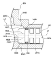
図9A~図9Dに示されるように、シリンダ部204は、金属製の材料を用いて形成されている。具体的には、シリンダ部204は、筒状に形成されていると共に前述のピストン部160の挿入部160A(図8A~図8D参照)が挿入される第1筒状部204Aと、当該第1筒状部204Aに連通されていると共に内部にガスジェネレータ194のガスが供給される第2筒状部204Bと、を備えている。第1筒状部204Aの内周面は、前述のOリング208の形状に対応して円筒面状に形成されている。また、第1筒状部204Aの第2筒状部204B側の部位204Cは、第2筒状部204Bにおける第1筒状部204A側の部位204Dと径方向に重なっている。
第2筒状部204Bの中心軸L2は、第1筒状部204Aの中心軸L1に対して当該第1筒状部204Aの径方向にオフセットして配置されている。これにより、第2筒状部204Bから第1筒状部204Aに掛けてのシリンダ部204内のガスの経路がクランク状に曲がっている。また、シリンダ部204内のガスの経路がクランク状に形成されていることにより、第1筒状部204Aと第2筒状部204Bとの境界部には、すなわち、第1筒状部204Aにおける第2筒状部204B側の端部には、ピストン部160の当接部160Fが当接する被当接部204Eが形成されている。そして、図10に示されるように、ピストン部160の当接部160Fが被当接部204Eに当接された状態が、ピストン部160のシリンダ部204への組付け完了状態となるように設定されている。
また、図9A~図9Dに示されるように、第2筒状部204Bにおける第1筒状部204Aとは反対側の端部は、ガスジェネレータ194が係合される被係合部204Fとされている。さらに第2筒状部204Bにおいて被係合部204Fよりも第1筒状部204A側の部位には、2箇所の段差部204Gが形成されている。これにより、第2筒状部204Bの流路面積が、第1筒状部204A側に向かうにつれて狭くなるように設定されている。
図9A~図9Cに示されるように、シリンダ部204は、舌片状に形成された固定フランジ部204Hを備えている。そして、このフランジ部204Hがボディ122に固定されることで、シリンダ部204がボディ122に取付けられるようになっている。
(本実施形態の作用並びに効果)
次に、本実施形態の作用並びに効果について説明する。
次に、本実施形態の作用並びに効果について説明する。
図1に示されるように、本実施形態に係るウェビング巻取装置10では、スプール20、ロックギヤ24、メイントーションシャフト32、サブトーションシャフト44、及びクラッチ機構52(スリーブ54、クラッチベース82、クラッチプレート100及びスクリュー108を含む)が一体に巻取方向及び引出方向へ回転可能に構成されている。そのため、ウェビング22がスプール20から引出されることで、ウェビング22が車両の乗員の身体に装着されるようになっている。また、ウェビング22が車両の乗員の身体に装着された状態で、例えば、車両が急減速状態になり、ロック機構が作動すると、ロックギヤ24の引出方向への回転が阻止される。その結果、このロックギヤ24にメイントーションシャフト32を介して連結されたスプール20の引出方向への回転が制限されて、スプール20からのウェビング22の引出しが制限される。したがって、車両前方へ移動しようとする乗員の身体がウェビング22によって拘束される。
また、ロックギヤ24の引出方向への回転が阻止された状態で、更に大きな力で乗員の身体がウェビング22を引張り、この引張力に基づく引出方向へのスプール20の回転力がメイントーションシャフト32の第一エネルギ吸収部38の耐捩れ荷重(耐変形荷重)を上回ると、フォースリミッタ機構31が作動されて、第一エネルギ吸収部38の捩れ(変形)により、スプール20のフォースリミッタ荷重(第一エネルギ吸収部38の耐捩れ荷重)以上での引出方向への回転が許容される。
したがって、第一エネルギ吸収部38の捩れによりスプール20が引出方向へ回転されてスプール20からウェビング22が引出されることで、ウェビング22による乗員の胸部への負荷(負担)が軽減される。また第一エネルギ吸収部38の捩れ分だけウェビング22の引張りに供される乗員の運動エネルギが吸収される。
一方、上述のように、ロックギヤ24に対してスプール20が引出方向に回転されるということは、ロックギヤ24がスプール20に対して相対的に巻取方向へ回転されると言うことである。したがって、ロックギヤ24がスプール20に対して巻取方向へ相対回転されると、トリガワイヤ40における基端部40Aよりも先端側がスプール20の孔部42に挿入されたまま、このトリガワイヤ40の基端部40Aがメイントーションシャフト32の周方向に移動されるので、このトリガワイヤ40における基端部40Aよりも先端側が孔部42に対してロックギヤ24側に引張られる。
これにより、トリガワイヤ40の先端部40Bがクラッチガイド64の孔部65とクラッチカバー88の孔部91から引抜かれて、スプール20及びクラッチカバー88に対するクラッチガイド64の相対回転の阻止状態が解消される。
そして、コイルスプリング98の付勢力により、クラッチガイド64が非作動位置から作動位置へと回転されると、クラッチカバー88の孔部89(クラッチプレート100の回動軸106)とクラッチガイド64の連結壁部74との間隔が短くなり、クラッチプレート100の円弧部104の先端が連結壁部74によってクラッチガイド64の接線方向に押圧(案内)される。これにより、クラッチプレート100がロックリング190側へ回動され(図5Aの矢印R参照)、クラッチプレート100のローレット歯104Aがロックリング190のローレット歯190Aと噛合う(図5Bに図示した状態)。これにより、クラッチプレート100とロックリング190とが結合される。また、このときには、クラッチベース82に形成された係止部86がクラッチプレート100のアーム部102の基端部を引出方向へ押すことにより、クラッチプレート100がロックリング190に押付けられ、両者の結合状態が維持される。これにより、クラッチ機構52(スリーブ54、クラッチベース82及びクラッチプレート100)の引出方向への回転と一体に、ロックリング190が引出方向へ回転しようとする。
また、図示しない制御装置は、体格検出手段からの信号に基づいて、乗員の体格が予め定められた基準値以上であるか否かを判定すると共に、衝突検出手段からの信号に基づいて、車両が衝突したか否かを判定している。そして、制御装置が、乗員の体格が予め定められた基準値以上であると判定した場合では、図6及び図7に示されたガスジェネレータ194が作動されないため、パウル150の係合部156が、ロック位置に配置されて、ロックリング190の切欠部192に係合している。このため、ロックリング190の引出方向への回転がロック(阻止)されることで、クラッチ機構52(スリーブ54、クラッチベース82及びクラッチプレート100)の引出方向への回転が阻止される。
そして、図1に示されるように、スリーブ54の引出方向への回転が阻止された状態で、更に大きな力で乗員の身体がウェビング22を引張り、この引張力に基づく引出方向へのスプール20の回転力がメイントーションシャフト32の第一エネルギ吸収部38の耐捩れ荷重(耐変形荷重)とサブトーションシャフト44の第二エネルギ吸収部50の耐捩れ荷重(耐変形荷重)との合計を上回ると、第一エネルギ吸収部38及び第二エネルギ吸収部50の捩れ(変形)により、スプール20のフォースリミッタ荷重(第一エネルギ吸収部38の耐捩れ荷重と第二エネルギ吸収部50の耐捩れ荷重との合計)以上での引出方向への回転が許容される。
したがって、第一エネルギ吸収部38及び第二エネルギ吸収部50の捩れによりスプール20が引出方向へ回転されてスプール20からウェビング22が引出されることで、ウェビング22による乗員の胸部への負荷(負担)が軽減されると共に、第一エネルギ吸収部38及び第二エネルギ吸収部50の捩れ分だけウェビング22の引張りに供される乗員の運動エネルギが吸収される。
一方、制御装置が、体格検出手段からの信号に基づいて、乗員の体格が予め定められた基準値未満であると判定すると共に、衝突検出手段の信号に基づいて、車両が衝突したと判定した場合には、制御装置の制御により図6及び図7に示されたガスジェネレータ194が作動される。
ガスジェネレータ194が作動されると、ガスジェネレータ194のガス噴出部194Aから噴出したガスが、シリンダ部204の第2筒状部204B内に供給され、第2筒状部204B内及び当該第2筒状部204Bと連通された第1筒状部204A内の圧力が高まる。これにより、第1筒状部204A内に設けられたピストン部160が、第1筒状部204A内に沿って移動される。そして、移動されたピストン部160の押圧部160Cがパウル150のアーム部154を押圧する。その結果、パウル150の係止孔158に挿通されたシェアピン132Bがせん断され、パウル150が軸支部132Aを軸中心として回転される。そして、パウル150の係合部156とロックリング190の切欠部192との係合が外れる(この状態のパウル150の位置を「解除位置」という)。その結果、ロックリング190の引出方向への回転が許容されることで、クラッチ機構52(スリーブ54、クラッチベース82及びクラッチプレート100)及びスプール20と共にロックリング190が引出方向へ回転可能にされる。このため、第二エネルギ吸収部50に捩れは生じないため、第一エネルギ吸収部38の捩れ(変形)により、スプール20のフォースリミッタ荷重(第一エネルギ吸収部38の耐捩れ荷重)以上での引出方向への回転が許容される。
すなわち、乗員の体格が予め定められた基準値以上である場合では、フォースリミッタ荷重が第一エネルギ吸収部38の耐捩れ荷重と第二エネルギ吸収部50の耐捩れ荷重との合計にされて、フォースリミッタ荷重の荷重値が高荷重にされる。一方、乗員の体格が予め定められた基準値未満であり、車両の衝突が検出された場合には、フォースリミッタ荷重が第一エネルギ吸収部38の耐捩れ荷重にされて、フォースリミッタ荷重の荷重値が低荷重にされる。このため、乗員を体格に応じて適切に保護することができる。
ここで、本実施形態では、図10に示されるように、ピストン部160の当接部160Fがシリンダ部204に設けられた被当接部204Eに当接された状態が、ピストン部160のシリンダ部204への組付け完了状態となるように設定されている。当該設定とすることにより、シリンダ部204内におけるピストン部160とガスジェネレータ194との間の空間の容積が安定し、ガスジェネレータ194が作動された際のシリンダ部204内の圧力上昇特性を安定させることができる。これにより、ピストン部160の作動力(ピストン部160からパウル150に入力される荷重)を安定させることができる。
また、本実施形態では、シリンダ部204内におけるピストン部160とガスジェネレータ194との間の空間の容積に過度なバラつきが生じないため、当該過度な容積のバラつきを考慮してガスジェネレータ194の出力を設定しなくてもよい。すなわち、当該過度な容積のバラつきを考慮してガスジェネレータ194の出力を高めなくてもよい。これにより、ガスジェネレータ194の体格の大型化を抑制することができ、ひいては、フォースリミッタ荷重切替機構120の体格の大型化を抑制することができる。
また、本実施形態では、ピストン部160の挿入部160AにおいてOリング取付溝160Bが形成された部位よりも基端側の部位が、押圧部160Cとは反対側に向かうにつれて次第に窄まるように形成された窄み部160Dとされている。これにより、第2筒状部204Bから第1筒状部204A内に流れ込んだガスジェネレータ194のガスをOリング208側に向けて速やかに流すことができ、Oリング208周辺の圧力上昇速度を速めることができる。その結果、ガスジェネレータ194が作動された際に、Oリング208を速やかに変形させる(Oリング208をピストン部160の挿入部160Aの軸方向に潰れるように変形させる)ことが可能となり、Oリング208によるガスのシール性を高めることができる。
さらに、本実施形態では、4つのV字溝160Eが窄み部160Dに形成されている。これにより、第2筒状部204Bから第1筒状部204A内に流れ込んだガスジェネレータ194のガスを窄み部160Dに形成された4つのV字溝160Eを通じてOリング208が嵌まり込むOリング取付溝160B内に速やかに流すことができ、Oリング208周辺の圧力上昇速度を速めることができる。その結果、ガスジェネレータ194が作動された際に、Oリング208を速やかに変形させる(Oリング208をピストン部160の挿入部160Aの軸方向に潰れるように変形させる)ことが可能となり、Oリング208によるガスのシール性を高めることができる。
また、本実施形態では、ガスジェネレータ194のガスが供給される第2筒状部204Bの流路面積が、第1筒状部204A側に向かうにつれて狭くなるように設定されている。これにより、ガスジェネレータ194のガスを第1筒状部204Aに速やかに流すことが可能となる。その結果、ガスジェネレータ194の作動開始からピストン部160の移動開始までの時間を短縮することが可能となる。
なお、本実施形態では、ガスジェネレータ194のガスが供給される第2筒状部204Bの流路面積を第1筒状部204A側に向かうにつれて狭くなるように設定した例について説明したが、本発明はこれに限定されない。第2筒状部204Bの流路面積を上記のように設定するか否かについては、シリンダ部204内におけるピストン部160とガスジェネレータ194との間の空間の容積等を考慮して適宜設定すればよい。
また、本実施形態では、ピストン部160に窄み部160Dを設けると共に当該窄み部160DにV字溝160Eを設けた例について説明したが、本発明はこれに限定されない。ピストン部160に窄み部160D及びV字溝160Eを設けるか否かについてはOリング208のシール性等を考慮して適宜設定すればよい。
(クラッチ機構52の仮保持構造)
次に、図11及び図12を用いて、本実施形態のクラッチ機構52の仮保持構造について説明する。
次に、図11及び図12を用いて、本実施形態のクラッチ機構52の仮保持構造について説明する。
図11に示されるように、本実施形態のクラッチ機構52では、クラッチカバー88のガイド爪部96が、クラッチガイド64に設けられたガイド孔70A内に配置されると共に当該ガイド孔70Aに沿って移動されることにより、クラッチガイド64が、クラッチカバー88に対して、図5Bに示された作動位置と、図4に示された非作動位置との間で相対回転可能とされている。
また、ウェビング巻取装置10の組立工程においては、トリガワイヤ40の先端部40B(図1参照)が、クラッチガイド64及びクラッチカバー88に形成された孔部65,91(図1参照)にそれぞれ挿入される(トリガワイヤ挿入工程)。これにより、クラッチガイド64が非作動位置に拘束されるようになっている。
ところで、図11に示されるように、クラッチ機構52が組立てられた状態では、一対のコイルスプリング98の付勢力により、クラッチガイド64が作動位置に配置される。これにより、クラッチプレート100のローレット歯104Aがクラッチガイド64の外周部よりも外側に飛出した状態となっている。
しかしながら、上記のトリガワイヤ挿入工程の作業性等を考慮すると、クラッチガイド64が非作動位置に位置された状態のクラッチ機構52が、トリガワイヤ挿入工程を行う製造ラインに搬入されることが望ましい。
そこで、本実施形態では、図12A及び図12Bに示されるように、クラッチガイド64に設けられたガイド孔70A内の一部に、クラッチカバー88のガイド爪部96が係止される係止部70Bを設けている。そして、クラッチカバー88のガイド爪部96が係止部70Bに係止されることで、クラッチガイド64が非作動位置に配置された状態が保たれるようになっている。なお、トリガワイヤ挿入工程を経た後においては、ガイド爪部96を移動させて、当該ガイド爪部96と係止部70Bとの係合を解除すればよい。
以上説明したように、本実施形態では、上記仮保持構造を備えていることにより、トリガワイヤ挿入工程の作業性を向上させることができる。
以上、本発明の一実施形態について説明したが、本発明は、上記に限定されるものでなく、その主旨を逸脱しない範囲内において上記以外にも種々変形して実施することが可能であることは勿論である。
2015年4月6日に出願された日本国特許出願2015-077660号の開示は、その全体が参照により本明細書に取り込まれる。
Claims (3)
- 乗員に装着されるウェビングが巻取られ、前記ウェビングが引出されることで引出方向へ回転されるスプールと、
車両の緊急時に前記スプールの引出方向への回転を規制するロック部と、
前記ロック部が前記スプールの引出方向への回転を規制した際に前記スプールのフォースリミッタ荷重以上での引出方向への回転を許容するフォースリミッタ機構と、
変位されることで前記フォースリミッタ荷重を切替える切替部材と、
筒状に形成された第1筒状部と、中心軸が前記第1筒状部の中心軸に対してオフセットして配置されていると共に前記第1筒状部に連通された第2筒状部と、前記第1筒状部と前記第2筒状部との境界部に設けられた被当接部と、を有するシリンダ部と、
作動されて前記第2筒状部内にガスを供給するガス発生装置と、
前記被当接部に当接された状態で前記第1筒状部内に配置されており、前記ガス発生装置が作動されて前記第2筒状部内及び前記第1筒状部内の圧力が上昇することで、前記第1筒状部に沿って移動されて、前記切替部材を押圧して変位させるピストン部と、
を備えたウェビング巻取装置。 - 前記ピストン部の外周部には、該ピストン部と前記第1筒状部との間をシールすると共に弾性を有する材料を用いて形成されたシール部材が取付けられており、
前記ピストン部において前記シール部材が取付けられた部分よりも前記被当接部側の部位が窄まっている請求項1記載のウェビング巻取装置。 - 前記ピストン部の外周部には、該ピストン部と前記第1筒状部との間をシールすると共に弾性を有する材料を用いて形成されたシール部材が嵌まり込む凹溝が形成されており、
前記ピストン部において前記凹溝が形成された部位よりも前記被当接部側には、前記凹溝と連通されていると共に前記ガス発生装置のガスが通過する連通部が設けられている請求項1又は請求項2記載のウェビング巻取装置。
Priority Applications (1)
| Application Number | Priority Date | Filing Date | Title |
|---|---|---|---|
| US15/561,811 US10518744B2 (en) | 2015-04-06 | 2016-03-28 | Webbing take-up device |
Applications Claiming Priority (2)
| Application Number | Priority Date | Filing Date | Title |
|---|---|---|---|
| JP2015-077660 | 2015-04-06 | ||
| JP2015077660A JP6306534B2 (ja) | 2015-04-06 | 2015-04-06 | ウェビング巻取装置 |
Publications (1)
| Publication Number | Publication Date |
|---|---|
| WO2016163265A1 true WO2016163265A1 (ja) | 2016-10-13 |
Family
ID=57072510
Family Applications (1)
| Application Number | Title | Priority Date | Filing Date |
|---|---|---|---|
| PCT/JP2016/059982 Ceased WO2016163265A1 (ja) | 2015-04-06 | 2016-03-28 | ウェビング巻取装置 |
Country Status (3)
| Country | Link |
|---|---|
| US (1) | US10518744B2 (ja) |
| JP (1) | JP6306534B2 (ja) |
| WO (1) | WO2016163265A1 (ja) |
Families Citing this family (3)
| Publication number | Priority date | Publication date | Assignee | Title |
|---|---|---|---|---|
| CN109153368B (zh) * | 2016-04-06 | 2021-08-27 | Trw汽车股份有限公司 | 具有第二力限制器的安全带卷收器 |
| JP7201158B2 (ja) * | 2018-08-08 | 2023-01-10 | 株式会社東海理化電機製作所 | ウェビング巻取装置 |
| JP7754726B2 (ja) * | 2022-01-12 | 2025-10-15 | 株式会社東海理化電機製作所 | ウェビング巻取装置 |
Citations (4)
| Publication number | Priority date | Publication date | Assignee | Title |
|---|---|---|---|---|
| US20080061180A1 (en) * | 2006-09-12 | 2008-03-13 | Webber James L | Compact dual-level load limiting seat belt retractor |
| JP2008213538A (ja) * | 2007-02-28 | 2008-09-18 | Tokai Rika Co Ltd | ウエビング巻取装置 |
| US20130248633A1 (en) * | 2010-11-06 | 2013-09-26 | Trw Automotive Gmbh | Force limiting device, belt retractor having a force limiting device, and method for switching over a force limiting device |
| WO2015076377A1 (ja) * | 2013-11-25 | 2015-05-28 | タカタ株式会社 | シートベルトリトラクタ及びこれを備えるシートベルト装置 |
Family Cites Families (4)
| Publication number | Priority date | Publication date | Assignee | Title |
|---|---|---|---|---|
| DE19927427C2 (de) | 1999-06-16 | 2002-11-14 | Autoliv Dev | Gurtaufroller mit schaltbarem Kraftbegrenzer |
| JP4908927B2 (ja) * | 2005-08-22 | 2012-04-04 | 株式会社東海理化電機製作所 | ウエビング巻取装置 |
| JP5528940B2 (ja) * | 2010-07-30 | 2014-06-25 | 株式会社東海理化電機製作所 | ガス流通構造及びウェビング巻取装置 |
| JP5792110B2 (ja) * | 2012-04-05 | 2015-10-07 | 株式会社東海理化電機製作所 | ウェビング巻取装置 |
-
2015
- 2015-04-06 JP JP2015077660A patent/JP6306534B2/ja active Active
-
2016
- 2016-03-28 WO PCT/JP2016/059982 patent/WO2016163265A1/ja not_active Ceased
- 2016-03-28 US US15/561,811 patent/US10518744B2/en active Active
Patent Citations (4)
| Publication number | Priority date | Publication date | Assignee | Title |
|---|---|---|---|---|
| US20080061180A1 (en) * | 2006-09-12 | 2008-03-13 | Webber James L | Compact dual-level load limiting seat belt retractor |
| JP2008213538A (ja) * | 2007-02-28 | 2008-09-18 | Tokai Rika Co Ltd | ウエビング巻取装置 |
| US20130248633A1 (en) * | 2010-11-06 | 2013-09-26 | Trw Automotive Gmbh | Force limiting device, belt retractor having a force limiting device, and method for switching over a force limiting device |
| WO2015076377A1 (ja) * | 2013-11-25 | 2015-05-28 | タカタ株式会社 | シートベルトリトラクタ及びこれを備えるシートベルト装置 |
Also Published As
| Publication number | Publication date |
|---|---|
| JP2016196264A (ja) | 2016-11-24 |
| US10518744B2 (en) | 2019-12-31 |
| JP6306534B2 (ja) | 2018-04-04 |
| US20180118157A1 (en) | 2018-05-03 |
Similar Documents
| Publication | Publication Date | Title |
|---|---|---|
| JP4819645B2 (ja) | ウエビング巻取装置 | |
| CN1919661B (zh) | 带状物卷绕装置 | |
| JP4885764B2 (ja) | ウエビング巻取装置 | |
| JP5587142B2 (ja) | ウエビング巻取装置 | |
| JP6498478B2 (ja) | ウェビング巻取装置 | |
| JP6306534B2 (ja) | ウェビング巻取装置 | |
| JP2013001313A (ja) | ウェビング巻取装置 | |
| JP5384438B2 (ja) | ウエビング巻取装置 | |
| JP5792110B2 (ja) | ウェビング巻取装置 | |
| JP5384436B2 (ja) | ウエビング巻取装置 | |
| JP2009184520A (ja) | ウエビング巻取装置 | |
| JP5763006B2 (ja) | ウェビング巻取装置 | |
| JP5529076B2 (ja) | ウエビング巻取装置 | |
| JP5539042B2 (ja) | ウェビング巻取装置 | |
| JP5641882B2 (ja) | ウェビング巻取装置 | |
| JP5528940B2 (ja) | ガス流通構造及びウェビング巻取装置 | |
| JP4922131B2 (ja) | ウエビング巻取装置 | |
| JP2014180905A (ja) | ウェビング巻取装置 | |
| JP2014162291A (ja) | ウェビング巻取装置 | |
| US20170291571A1 (en) | Webbing take-up device | |
| US10513421B2 (en) | Webbing take-up device | |
| JP2020023271A (ja) | ウェビング巻取装置 | |
| JP5518685B2 (ja) | ウェビング巻取装置 | |
| JP2000043677A (ja) | シートベルトリトラクタ |
Legal Events
| Date | Code | Title | Description |
|---|---|---|---|
| 121 | Ep: the epo has been informed by wipo that ep was designated in this application |
Ref document number: 16776433 Country of ref document: EP Kind code of ref document: A1 |
|
| WWE | Wipo information: entry into national phase |
Ref document number: 15561811 Country of ref document: US |
|
| NENP | Non-entry into the national phase |
Ref country code: DE |
|
| 122 | Ep: pct application non-entry in european phase |
Ref document number: 16776433 Country of ref document: EP Kind code of ref document: A1 |