WO2016159364A1 - 歩行者判定装置 - Google Patents
歩行者判定装置 Download PDFInfo
- Publication number
- WO2016159364A1 WO2016159364A1 PCT/JP2016/060955 JP2016060955W WO2016159364A1 WO 2016159364 A1 WO2016159364 A1 WO 2016159364A1 JP 2016060955 W JP2016060955 W JP 2016060955W WO 2016159364 A1 WO2016159364 A1 WO 2016159364A1
- Authority
- WO
- WIPO (PCT)
- Prior art keywords
- target
- likelihood
- radar
- pedestrian
- radar target
- Prior art date
- Legal status (The legal status is an assumption and is not a legal conclusion. Google has not performed a legal analysis and makes no representation as to the accuracy of the status listed.)
- Ceased
Links
Images




Classifications
-
- G—PHYSICS
- G01—MEASURING; TESTING
- G01S—RADIO DIRECTION-FINDING; RADIO NAVIGATION; DETERMINING DISTANCE OR VELOCITY BY USE OF RADIO WAVES; LOCATING OR PRESENCE-DETECTING BY USE OF THE REFLECTION OR RERADIATION OF RADIO WAVES; ANALOGOUS ARRANGEMENTS USING OTHER WAVES
- G01S7/00—Details of systems according to groups G01S13/00, G01S15/00, G01S17/00
- G01S7/02—Details of systems according to groups G01S13/00, G01S15/00, G01S17/00 of systems according to group G01S13/00
- G01S7/41—Details of systems according to groups G01S13/00, G01S15/00, G01S17/00 of systems according to group G01S13/00 using analysis of echo signal for target characterisation; Target signature; Target cross-section
- G01S7/411—Identification of targets based on measurements of radar reflectivity
- G01S7/412—Identification of targets based on measurements of radar reflectivity based on a comparison between measured values and known or stored values
-
- B—PERFORMING OPERATIONS; TRANSPORTING
- B60—VEHICLES IN GENERAL
- B60T—VEHICLE BRAKE CONTROL SYSTEMS OR PARTS THEREOF; BRAKE CONTROL SYSTEMS OR PARTS THEREOF, IN GENERAL; ARRANGEMENT OF BRAKING ELEMENTS ON VEHICLES IN GENERAL; PORTABLE DEVICES FOR PREVENTING UNWANTED MOVEMENT OF VEHICLES; VEHICLE MODIFICATIONS TO FACILITATE COOLING OF BRAKES
- B60T7/00—Brake-action initiating means
- B60T7/12—Brake-action initiating means for automatic initiation; for initiation not subject to will of driver or passenger
- B60T7/22—Brake-action initiating means for automatic initiation; for initiation not subject to will of driver or passenger initiated by contact of vehicle, e.g. bumper, with an external object, e.g. another vehicle, or by means of contactless obstacle detectors mounted on the vehicle
-
- B—PERFORMING OPERATIONS; TRANSPORTING
- B60—VEHICLES IN GENERAL
- B60T—VEHICLE BRAKE CONTROL SYSTEMS OR PARTS THEREOF; BRAKE CONTROL SYSTEMS OR PARTS THEREOF, IN GENERAL; ARRANGEMENT OF BRAKING ELEMENTS ON VEHICLES IN GENERAL; PORTABLE DEVICES FOR PREVENTING UNWANTED MOVEMENT OF VEHICLES; VEHICLE MODIFICATIONS TO FACILITATE COOLING OF BRAKES
- B60T8/00—Arrangements for adjusting wheel-braking force to meet varying vehicular or ground-surface conditions, e.g. limiting or varying distribution of braking force
- B60T8/17—Using electrical or electronic regulation means to control braking
-
- G—PHYSICS
- G01—MEASURING; TESTING
- G01S—RADIO DIRECTION-FINDING; RADIO NAVIGATION; DETERMINING DISTANCE OR VELOCITY BY USE OF RADIO WAVES; LOCATING OR PRESENCE-DETECTING BY USE OF THE REFLECTION OR RERADIATION OF RADIO WAVES; ANALOGOUS ARRANGEMENTS USING OTHER WAVES
- G01S13/00—Systems using the reflection or reradiation of radio waves, e.g. radar systems; Analogous systems using reflection or reradiation of waves whose nature or wavelength is irrelevant or unspecified
- G01S13/86—Combinations of radar systems with non-radar systems, e.g. sonar, direction finder
- G01S13/867—Combination of radar systems with cameras
-
- G—PHYSICS
- G01—MEASURING; TESTING
- G01S—RADIO DIRECTION-FINDING; RADIO NAVIGATION; DETERMINING DISTANCE OR VELOCITY BY USE OF RADIO WAVES; LOCATING OR PRESENCE-DETECTING BY USE OF THE REFLECTION OR RERADIATION OF RADIO WAVES; ANALOGOUS ARRANGEMENTS USING OTHER WAVES
- G01S13/00—Systems using the reflection or reradiation of radio waves, e.g. radar systems; Analogous systems using reflection or reradiation of waves whose nature or wavelength is irrelevant or unspecified
- G01S13/88—Radar or analogous systems specially adapted for specific applications
- G01S13/93—Radar or analogous systems specially adapted for specific applications for anti-collision purposes
- G01S13/931—Radar or analogous systems specially adapted for specific applications for anti-collision purposes of land vehicles
-
- G—PHYSICS
- G06—COMPUTING OR CALCULATING; COUNTING
- G06V—IMAGE OR VIDEO RECOGNITION OR UNDERSTANDING
- G06V20/00—Scenes; Scene-specific elements
- G06V20/50—Context or environment of the image
- G06V20/56—Context or environment of the image exterior to a vehicle by using sensors mounted on the vehicle
- G06V20/58—Recognition of moving objects or obstacles, e.g. vehicles or pedestrians; Recognition of traffic objects, e.g. traffic signs, traffic lights or roads
-
- G—PHYSICS
- G06—COMPUTING OR CALCULATING; COUNTING
- G06V—IMAGE OR VIDEO RECOGNITION OR UNDERSTANDING
- G06V40/00—Recognition of biometric, human-related or animal-related patterns in image or video data
- G06V40/10—Human or animal bodies, e.g. vehicle occupants or pedestrians; Body parts, e.g. hands
-
- G—PHYSICS
- G06—COMPUTING OR CALCULATING; COUNTING
- G06V—IMAGE OR VIDEO RECOGNITION OR UNDERSTANDING
- G06V40/00—Recognition of biometric, human-related or animal-related patterns in image or video data
- G06V40/20—Movements or behaviour, e.g. gesture recognition
-
- G—PHYSICS
- G08—SIGNALLING
- G08G—TRAFFIC CONTROL SYSTEMS
- G08G1/00—Traffic control systems for road vehicles
- G08G1/16—Anti-collision systems
- G08G1/166—Anti-collision systems for active traffic, e.g. moving vehicles, pedestrians, bikes
-
- B—PERFORMING OPERATIONS; TRANSPORTING
- B60—VEHICLES IN GENERAL
- B60R—VEHICLES, VEHICLE FITTINGS, OR VEHICLE PARTS, NOT OTHERWISE PROVIDED FOR
- B60R21/00—Arrangements or fittings on vehicles for protecting or preventing injuries to occupants or pedestrians in case of accidents or other traffic risks
-
- B—PERFORMING OPERATIONS; TRANSPORTING
- B60—VEHICLES IN GENERAL
- B60T—VEHICLE BRAKE CONTROL SYSTEMS OR PARTS THEREOF; BRAKE CONTROL SYSTEMS OR PARTS THEREOF, IN GENERAL; ARRANGEMENT OF BRAKING ELEMENTS ON VEHICLES IN GENERAL; PORTABLE DEVICES FOR PREVENTING UNWANTED MOVEMENT OF VEHICLES; VEHICLE MODIFICATIONS TO FACILITATE COOLING OF BRAKES
- B60T2201/00—Particular use of vehicle brake systems; Special systems using also the brakes; Special software modules within the brake system controller
- B60T2201/02—Active or adaptive cruise control system; Distance control
- B60T2201/022—Collision avoidance systems
-
- B—PERFORMING OPERATIONS; TRANSPORTING
- B60—VEHICLES IN GENERAL
- B60T—VEHICLE BRAKE CONTROL SYSTEMS OR PARTS THEREOF; BRAKE CONTROL SYSTEMS OR PARTS THEREOF, IN GENERAL; ARRANGEMENT OF BRAKING ELEMENTS ON VEHICLES IN GENERAL; PORTABLE DEVICES FOR PREVENTING UNWANTED MOVEMENT OF VEHICLES; VEHICLE MODIFICATIONS TO FACILITATE COOLING OF BRAKES
- B60T2210/00—Detection or estimation of road or environment conditions; Detection or estimation of road shapes
- B60T2210/30—Environment conditions or position therewithin
- B60T2210/32—Vehicle surroundings
-
- B—PERFORMING OPERATIONS; TRANSPORTING
- B60—VEHICLES IN GENERAL
- B60Y—INDEXING SCHEME RELATING TO ASPECTS CROSS-CUTTING VEHICLE TECHNOLOGY
- B60Y2400/00—Special features of vehicle units
- B60Y2400/30—Sensors
- B60Y2400/301—Sensors for position or displacement
- B60Y2400/3015—Optical cameras
-
- B—PERFORMING OPERATIONS; TRANSPORTING
- B60—VEHICLES IN GENERAL
- B60Y—INDEXING SCHEME RELATING TO ASPECTS CROSS-CUTTING VEHICLE TECHNOLOGY
- B60Y2400/00—Special features of vehicle units
- B60Y2400/30—Sensors
- B60Y2400/301—Sensors for position or displacement
- B60Y2400/3017—Radars
-
- G—PHYSICS
- G01—MEASURING; TESTING
- G01S—RADIO DIRECTION-FINDING; RADIO NAVIGATION; DETERMINING DISTANCE OR VELOCITY BY USE OF RADIO WAVES; LOCATING OR PRESENCE-DETECTING BY USE OF THE REFLECTION OR RERADIATION OF RADIO WAVES; ANALOGOUS ARRANGEMENTS USING OTHER WAVES
- G01S13/00—Systems using the reflection or reradiation of radio waves, e.g. radar systems; Analogous systems using reflection or reradiation of waves whose nature or wavelength is irrelevant or unspecified
- G01S13/88—Radar or analogous systems specially adapted for specific applications
- G01S13/93—Radar or analogous systems specially adapted for specific applications for anti-collision purposes
- G01S13/931—Radar or analogous systems specially adapted for specific applications for anti-collision purposes of land vehicles
- G01S2013/93185—Controlling the brakes
Definitions
- the present invention relates to a pedestrian determination device.
- One aspect of the present invention has been made in view of the above circumstances, and an object thereof is to provide a pedestrian determination device that can more accurately determine whether a pedestrian is about to cross the front of the host vehicle. .
- the pedestrian determination device is a pedestrian determination device that determines whether or not a pedestrian crosses the traveling direction of the vehicle.
- the pedestrian determination device includes a target detection unit that detects a target as a radar target based on a reflected wave generated by reflection of the radar wave transmitted in the traveling direction, and the target
- the radar target detected by the target detection unit includes a likelihood calculation unit for calculating the likelihood that the radar target is a pedestrian crossing the traveling direction of the vehicle.
- the pedestrian determination device determines whether or not the calculated likelihood is equal to or greater than a preset threshold, and when it is determined that the calculated likelihood is equal to or greater than a preset threshold
- a pedestrian determination unit that determines the radar target as a pedestrian that crosses the traveling direction of the vehicle, and the likelihood calculation unit includes a target in which the radar targets are arranged at regular intervals. When detected as a part of a group, the likelihood of the radar target is made smaller than when the radar target is not detected as a part of a target group arranged at regular intervals.
- the pedestrian determination device is a pedestrian that crosses the traveling direction of a vehicle with respect to a radar target detected as a part of a target group arranged at regular intervals. Reduce the likelihood. With this likelihood control, it is possible to reduce the possibility that a target such as a pole provided at regular intervals along the road on which the vehicle travels will be erroneously determined as a pedestrian crossing the traveling direction of the vehicle. . As a result, the pedestrian determination device according to the first exemplary embodiment of the present invention can accurately determine whether or not the pedestrian is about to cross the traveling direction of the vehicle.
- the pedestrian determination device is a pedestrian determination device for determining whether or not the pedestrian crosses the traveling direction of the vehicle.
- the pedestrian determination device is picked up by a target detection unit that detects a target as a radar target based on a reflected wave generated by reflection of the radar wave sent in the traveling direction.
- An image acquisition unit that acquires an image of a landscape in the traveling direction of the vehicle, an image recognition unit that recognizes a target as an imaging target in the acquired image, and a pedestrian dictionary, When the imaging target recognized by the image recognition unit is the same target as the radar target detected by the target detection unit, the matching degree in matching between the imaging target and the pedestrian dictionary is acquired.
- the feature point in the imaging target is Optical flow acquisition unit for acquiring optical flow, movement speed acquisition unit for acquiring the movement speed of the radar target in the horizontal direction, and movement amount acquisition unit for acquiring the movement amount of the radar target in the horizontal direction And a likelihood calculating unit.
- the likelihood calculating unit Compared with the case where the radar target detected by the target detection unit is not detected as a part of the target group arranged at regular intervals, the likelihood that the radar target detected by the target detection unit is a pedestrian crossing the traveling direction of the vehicle.
- a first process for reducing a first likelihood representing A second process for increasing the second likelihood representing the likelihood that the radar target detected by the target detection unit is a pedestrian crossing the traveling direction of the vehicle as the degree of coincidence increases;
- the target detection is performed as compared to a case where the optical flow represents a movement in a direction other than the horizontal direction on the image.
- the radar target detected by the target detection unit is compared with the case where it is determined that the intensity in the reflected wave exceeds a preset threshold when When the fourth likelihood representing the likelihood of being a pedestrian crossing the traveling direction of the vehicle is increased and the magnitude of fluctuation in the reflected wave is determined to be equal to or greater than a preset threshold, the reflection A fourth process for increasing the fourth likelihood as compared with a case where the magnitude of fluctuation in the wave is determined to be less than a preset threshold; It is determined whether the moving speed in the lateral direction of the radar target is within a preset range, and it is determined that the moving speed in the lateral direction of the radar target is within a preset range.
- the radar target detected by the target detection unit is compared with the traveling direction of the vehicle as compared to a case where the lateral movement speed of the radar target is determined to be outside a preset range.
- a fifth process for increasing the fifth likelihood representing the likelihood of being a pedestrian crossing the vehicle, and whether or not the amount of lateral movement of the radar target is within a preset range When it is determined that the amount of movement of the radar target in the horizontal direction is within a preset range, it is determined that the amount of movement of the radar target in the horizontal direction is outside the preset range. Compared to the case where the target was detected by the target detection unit.
- At least one of the sixth processes for increasing the sixth likelihood representing the likelihood that the radar target is a pedestrian crossing the traveling direction of the vehicle is executed.
- the pedestrian determination device provides the first to sixth obtained by at least one of the first to sixth processes executed by the likelihood calculating unit.
- a pedestrian determination unit that determines whether or not the radar target is a pedestrian crossing the traveling direction of the vehicle based on at least one of the likelihoods.
- the likelihood calculation unit in the pedestrian determination apparatus executes at least one of the first to sixth processes, so that the radar target moves in the traveling direction of the vehicle. And calculating at least one corresponding likelihood out of the first to sixth likelihoods representing the likelihood of being a pedestrian crossing the vehicle, and based on the calculated at least one likelihood, the radar target is It can be determined whether or not the pedestrian crosses the traveling direction of the vehicle.
- the pedestrian determination device selects an appropriate process from the first to sixth processes according to the traveling state of the vehicle, for example, and performs the selected process. By executing, it is possible to calculate an appropriate likelihood corresponding to the traveling state of the vehicle. Therefore, according to the pedestrian determination device according to the second exemplary embodiment of the present invention, it can be accurately determined whether or not the pedestrian is going to cross the traveling direction of the vehicle.
- control ECU in connection with embodiment of this invention, and the component relevant to this control ECU. It is a flowchart showing the pedestrian determination process which control ECU shown in FIG. 1 performs. It is explanatory drawing showing an example of the target group regarding embodiment of this invention. It is explanatory drawing showing an example of the optical flow in connection with embodiment of this invention. It is explanatory drawing showing the moving speed in the horizontal direction of the radar target in connection with embodiment of this invention.
- Control ECU 1 Configuration of Control ECU 1 etc.
- the control ECU 1 and the configuration related to the control ECU 1 will be described with reference to FIG.
- the control ECU 1 is an example of a pedestrian determination device.
- the control ECU 1 is an in-vehicle device mounted on the vehicle 29.
- the vehicle 29 on which the control ECU 1 is mounted is referred to as the own vehicle 29.
- the control ECU 1 is a known computer including a CPU 1a, a memory 1b including a RAM and / or a ROM, and necessary peripheral devices.
- Control ECU1 (CPU1a) performs the process mentioned later by the program memorize
- the CPU 1a in the control ECU 1 functionally includes a target detection unit 3, a pedestrian-likelihood calculating unit 5, a pedestrian determination unit 7, an image acquisition unit 9, an image recognition unit 11, and a coincidence degree acquisition unit 13. , An optical flow acquisition unit 15, a movement speed acquisition unit 17, a movement amount acquisition unit 19, a brake execution condition setting unit 21, and a brake execution determination unit 22. The function of each unit will be described later.
- the host vehicle 29 includes an image sensor 23, a millimeter wave radar 25, and a brake ECU 27 in addition to the control ECU 1.
- the image sensor 23 captures a landscape in the traveling direction (for example, forward) of the host vehicle 29 as a frame image at predetermined intervals, and generates image data corresponding to the captured frame image of the forward landscape.
- the millimeter wave radar 25 sends a frequency-modulated millimeter wave radar wave and receives a reflected wave based on the transmitted radar wave, so that the traveling direction of the host vehicle 29 is based on the received reflected wave.
- a target for example, forward
- another vehicle, a pedestrian, a roadside object, an obstacle, etc. is detected.
- the millimeter wave radar 25 uses the received reflected wave as a reference to determine the distance (relative distance) from the host vehicle 29 to the target, the direction of the target with reference to the host vehicle 29, and the host vehicle 29.
- the relative speed of the target can be acquired.
- the brake ECU 27 is a known computer including a CPU, a memory including a RAM and / or a ROM, and necessary peripheral devices.
- the brake ECU 27 executes various processes according to a program stored in the ROM, for example. As one of the processes, the brake ECU 27 performs a process of automatically braking the host vehicle 29 when receiving an execution instruction to be described later from the control ECU 1.
- Pedestrian determination process executed by the control ECU 1 A pedestrian determination process repeatedly executed by the control ECU 1 at predetermined intervals will be described with reference to FIGS.
- step S1 of FIG. 2 the target detection unit 3 in the control ECU 1 uses the millimeter wave radar 25 to detect a target that exists in the traveling direction of the host vehicle 29 (in the present embodiment, the front).
- the distance of the detected target from the own vehicle 29, the direction of the detected target with reference to the own vehicle 29, and the relative speed of the detected target with reference to the own vehicle 29 are acquired.
- step S2 the pedestrian-likeness calculation unit 5 in the control ECU 1 uses the radar target according to the following processing procedure for the target detected by the millimeter wave radar 25 in step S1 (hereinafter referred to as a radar target).
- the likelihood (hereinafter referred to as reflected wave likelihood) is calculated on the basis of the reflected wave from.
- the likelihood is, for example, an index that represents the likelihood that the radar target is a crossing pedestrian as a numerical value.
- the pedestrian-likeness calculation unit 5, that is, the likelihood calculation unit 5 is generated by reflecting a reflected wave (a radar wave transmitted from the millimeter wave radar 25 is reflected by the radar target) when the radar target is detected in step S1. And the magnitude of the fluctuation of the reflected wave (the degree to which the intensity of the reflected wave fluctuates with time).
- the memory 1b information defining the relationship between the intensity of the reflected wave and the magnitude of the fluctuation and the reflected wave likelihood described later is stored in the memory 1b as a map M1 in a predetermined format, for example, a map format.
- a map M1 in a predetermined format, for example, a map format.
- the pedestrian-likeness calculation unit 5 calculates the value of the corresponding reflected wave likelihood in the map M1 by inputting the intensity of the reflected wave and the magnitude of the fluctuation into the map M1.
- the reflected wave likelihood calculated as described above is larger than the other cases when the intensity of the reflected wave is equal to or less than the first threshold value set in advance.
- the reflected wave likelihood is larger than in other cases when the magnitude of fluctuation in the reflected wave is equal to or greater than a second threshold value set in advance.
- the reflected wave likelihood is a parameter representing the probability (likelihood) that the radar target detected by the target detection unit 3 is a pedestrian crossing the traveling direction of the host vehicle 29.
- the reflected wave likelihood is a positive number, and the greater the value, the greater the probability that the radar target is a pedestrian that crosses the traveling direction of the host vehicle 29.
- step S3 the likelihood that the pedestrian-likeness calculation unit 5 is a pedestrian regarding the arrangement of the radar target according to the following processing procedure for the radar target detected in step S1 (hereinafter referred to as array likelihood) Calculate).
- the array likelihood is a parameter representing the probability that the radar target is a pedestrian crossing the traveling direction of the host vehicle 29.
- the pedestrian-likeness calculating unit 5 calculates the array likelihood when a plurality of targets arranged at regular intervals (hereinafter referred to as a target group) are detected in step S1. Is a part of the target group.
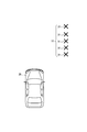
- a target group An example of a target group is shown in FIG.
- a target group 33 including a plurality of targets 31 arranged at regular intervals exists in the traveling direction of the host vehicle 29.
- Examples of the target group 33 include a row of poles provided at regular intervals along the end of the road on which the host vehicle 29 travels.
- the pedestrian-likeness calculation unit 5 sets the sequence likelihood value of the radar target as A1.
- the pedestrian-likeness calculation unit 5 sets the value of the array likelihood in the radar target as A2.
- A1 and A2 are constants, and their magnitude relationship is 0 ⁇ A1 ⁇ A2.
- the array likelihood is a parameter representing the probability that the target is a pedestrian crossing the host vehicle.
- the array likelihood is a positive number, and the greater the value, the greater the probability that the target is a pedestrian crossing the traveling direction of the host vehicle 29.
- step S4 the image acquisition unit 9 in the control ECU 1 uses the image sensor 23 to acquire a frame image in the traveling direction of the host vehicle 29.
- step S5 the image recognition unit 11 in the control ECU 1 recognizes a target (hereinafter referred to as an imaging target) in the frame image acquired in step S4 by a known image recognition technique.
- a dictionary (dictionary file) DF is prepared in advance for each target to be recognized (for example, a vehicle, a pedestrian, and a roadside object).
- Each dictionary DF is expressed by data (feature pattern data) representing a large number of feature quantity patterns in the corresponding target.
- the memory 1b includes a dictionary DF1 for pedestrians, a dictionary DF2 for vehicles, a dictionary DF3 for roadside objects, and the like.
- the image recognition unit 11 performs a matching process between the image data of the frame image and each of the plurality of dictionaries (that is, the feature pattern of each dictionary) to recognize the imaging target.
- step S6 the coincidence degree acquisition unit 13 and the pedestrian-likeness calculation unit 5 in the control ECU 1 are pedestrians regarding the coincidence degree of the radar target according to the following processing procedure for the radar target detected in step S1.
- a certain likelihood (hereinafter referred to as a matching likelihood) is calculated.
- the coincidence degree acquisition unit 13 specifies the same target (hereinafter referred to as the same target) as the radar target detected in step S1 among the respective imaging targets recognized in step S5. At this time, the coincidence degree acquisition unit 13 is the same as or approximated to the radar target whose distance and direction from the host vehicle 29 are detected in step S1 among the plurality of imaging targets recognized in step S5.
- the at least one imaging target can be the same target. That is, the coincidence degree acquisition unit 13 specifies, from among a plurality of imaging targets, imaging targets whose distances and directions from the corresponding radar target and the host vehicle 29 are the same or similar, as the same target.
- the matching degree acquisition unit 13 acquires the matching degree in matching between the same target (its image data) and the pedestrian dictionary DF1.
- the degree of coincidence means the degree of coincidence in matching between the same target and the corresponding dictionary. The greater the number of features common to the same target and the corresponding dictionary, the higher the degree of matching.
- the recognition result of the image recognition unit 11 can be used.
- the pedestrian-likeness calculation unit 5 calculates the matching likelihood of the radar target corresponding to the same target from the matching degree of the same target acquired as described above.
- the coincidence likelihood is a parameter representing the probability that the target is a pedestrian crossing the traveling direction of the host vehicle 29.
- the memory 1b information defining the relationship between the degree of coincidence and the likelihood of coincidence is held in the memory 1b as a map M2 in a predetermined format, for example, a map format. That is, the pedestrian-likeness calculation unit 5 calculates the corresponding likelihood likelihood value in the map M2 by inputting the matching degree of the same target acquired as described above into the map M2. The degree of coincidence likelihood calculated in this way is larger as the degree of coincidence is higher.
- the coincidence likelihood is a parameter representing the probability that the target is a pedestrian crossing the traveling direction of the host vehicle 29.
- the coincidence likelihood is a positive number, and the greater the value, the greater the probability that the target is a pedestrian crossing the traveling direction of the host vehicle 29.
- step S7 the optical flow acquisition unit 15 in the control ECU 1 extracts feature points in the same target between a plurality of frame images including the frame image acquired this time in step S4, and the optical flow of the extracted feature points. (Apparent movement of feature points between a plurality of images) is acquired. That is, the optical flow acquisition unit 15 is obtained by tracking feature points in the same target among a plurality of frame images acquired with a time difference.
- the feature point can be, for example, an edge of the same target in each frame image (a part where the difference in luminance between adjacent frame pixels is a predetermined value or more).
- FIG. 15 An example of the optical flow of the same target acquired by the optical flow acquisition unit 15 is shown in FIG.
- an optical flow 41 shown as an arrow mark representing the movement of the feature point 39 of the pedestrian 37 that is the same target recognized in the past frame image 35 to the current frame image is an optical flow. It has been acquired by the acquisition unit 15.
- step S8 when the radar target detected in step S1 is a radar target corresponding to the same target, the pedestrian-likeness calculation unit 5 relates to the optical flow of the radar target according to the following processing procedure.
- the likelihood of being a pedestrian (hereinafter referred to as optical flow likelihood) is calculated.
- the optical flow likelihood is a parameter representing the probability that the target is a pedestrian crossing the traveling direction of the host vehicle 29.
- the pedestrian-likeness calculation unit 5 determines that the optical flow acquired in step S7 is in the horizontal direction on the current frame image, that is, the width direction of the host vehicle 29 or the horizontal direction parallel to the road on which the host vehicle 29 travels, (In other words, whether or not the direction of the arrow of the optical flow is the horizontal direction).
- step S7 the horizontal movement in the optical flow does not include only the complete horizontal direction, and the movement in the optical flow may move in a direction inclined by a predetermined acute angle with respect to the complete horizontal direction. This is determined as a lateral movement in the optical flow.
- step S8 when each optical flow shows a lateral movement on the current frame image, the pedestrian-likeness calculation unit 5 corresponds to the same target that is the radar target detected in step S1.
- Let B1 be the value of the optical flow likelihood in the radar target.
- the pedestrian-likeness calculation unit 5 sets the value of the optical flow likelihood in the radar target as B2.
- B1 and B2 are constants, and their magnitude relationship is 0 ⁇ B2 ⁇ B1.
- the optical flow likelihood is a parameter that represents the probability that the target is a pedestrian crossing the front of the host vehicle 29.
- the optical flow likelihood is a positive number, and the greater the value, the greater the probability that the target is a pedestrian crossing the front of the host vehicle 29.
- step S9 the movement speed acquisition unit 17 in the control ECU 1 acquires the movement speed in the lateral direction for the radar target detected in step S1, and the movement amount acquisition unit 19 detects the radar object detected in step S1. Get the amount of movement in the horizontal direction for the mark.
- the moving speed in the horizontal direction and the moving amount in the horizontal direction of the radar target (indicated by reference numeral 38) detected in step S1 will be described.
- the relative speed of the radar target 38 detected in step S1 with respect to the host vehicle 29 is V.
- the lateral movement speed V1 of the radar target 38 is a component of the relative speed V in the vehicle width direction of the host vehicle 29.
- the movement amount of the radar target 38 in the horizontal direction is an integral amount of the movement speed V1 in a predetermined period.
- the moving speed acquisition unit 17 can acquire the moving speed in the horizontal direction and the moving amount in the horizontal direction of the radar target from the detection result of the millimeter wave radar 25, respectively. In addition, when the radar target corresponds to the same target, the moving speed acquisition unit 17 determines the moving speed in the horizontal direction of the radar target corresponding to the same target from a plurality of frame images acquired by the image sensor 23. You may acquire the movement amount in a horizontal direction.
- step S10 the likelihood that the pedestrian-likeness calculating unit 5 is a pedestrian regarding the moving speed in the lateral direction as described below with respect to the radar target detected in step S1 (hereinafter referred to as a moving speed likelihood). Calculate).
- the pedestrian-likeness calculation unit 5 determines whether or not the moving speed in the lateral direction of the radar target acquired in step S9 is within a preset range. This range is determined in advance as a range including a general speed of a pedestrian crossing the front of the host vehicle 29.
- the pedestrian-likeness calculation unit 5 sets the value of the movement speed likelihood of the radar target as C1.
- the pedestrian-likeness calculating unit 5 sets the value of the moving speed likelihood of the radar target as C2.
- C1 and C2 are constants, and their magnitude relationship is 0 ⁇ C2 ⁇ C1.
- the moving speed likelihood is a parameter representing the probability that the target is a pedestrian crossing the front of the host vehicle 29.
- the moving speed likelihood is a positive number, and the greater the value, the greater the probability that the target is a pedestrian crossing the front of the host vehicle 29.
- step S11 the likelihood that the pedestrian-likeness calculation unit 5 is a pedestrian regarding the amount of movement in the lateral direction with respect to the radar target detected in step S1 (hereinafter referred to as a movement amount likelihood). Calculate).
- the pedestrian-likeness calculation unit 5 determines whether or not the amount of lateral movement of the radar target acquired in step S9 is within a preset range. This range is determined in advance as a range including a general amount of movement of a pedestrian crossing the front of the host vehicle 29.
- the pedestrian likelihood calculation unit 5 sets the value of the movement amount likelihood of the radar target as D1.
- the pedestrian likelihood calculation unit 5 sets the value of the movement target likelihood of the radar target as D2.
- D1 and D2 are constants, and their magnitude relationship is 0 ⁇ D2 ⁇ D1.
- the movement amount likelihood is a parameter representing the probability that the target is a pedestrian crossing the front of the host vehicle 29.
- the likelihood of movement is a positive number, and the greater the value, the greater the probability that the target is a pedestrian crossing the front of the host vehicle 29.
- step S12 the pedestrian-likeness calculation unit 5 uses the reflected wave likelihood calculated in step S2, the array likelihood calculated in step S3, and the step S6 for the radar target detected in step S1.
- the calculated match likelihood, the optical flow likelihood calculated in step S8, the moving speed likelihood calculated in step S10, and the movement amount likelihood calculated in step S11 are multiplied, and the multiplication result is obtained.
- the likelihood of being a total pedestrian for the radar target (hereinafter referred to as the total likelihood).
- the coincidence likelihood and the optical flow likelihood are used when the radar target detected in step S1 is a radar target corresponding to the same target, and the radar target detected in step S1 is the same. If the target is not a target, the total likelihood is calculated by multiplying the reflected wave likelihood, the array likelihood, the moving speed likelihood, and the moving amount likelihood, excluding the optical flow likelihood and the coincidence likelihood.
- the total likelihood is when the intensity of the reflected wave generated based on the target (radar target) when a target is detected by the millimeter wave radar 25 is equal to or lower than a first threshold set in advance. Is larger than the other cases, and is larger than the other cases when the magnitude of the fluctuation in the reflected wave generated based on the radar target is equal to or larger than the second threshold value set in advance.
- the overall likelihood is smaller when the radar target is a part of the target group and otherwise.
- the overall likelihood increases as the matching degree in matching of the same target corresponding to the radar target increases.
- the total likelihood is greater when the optical flow at the feature point of the same target corresponding to the radar target indicates a lateral movement on the frame image than when indicating the other direction. large.
- the total likelihood is larger than the other cases when the lateral movement speed of the radar target is within a preset range. Further, the total likelihood is larger than the other cases when the lateral movement amount of the radar target is within a preset range.
- step S13 the pedestrian determination unit 7 determines whether or not the total likelihood of the radar target calculated in step S12 is equal to or greater than a preset third threshold value.
- the pedestrian determination process proceeds to step S14, and is calculated in step S12 of the radar target. If the determined overall likelihood is less than the third threshold value (negative determination in step S13), the pedestrian determination process proceeds to step S17.
- step S14 the pedestrian determination unit 7 in the control ECU 1 determines that the corresponding radar target is a target representing a pedestrian crossing the front of the host vehicle 29 (hereinafter referred to as a crossing target). .
- step S15 the brake execution condition setting unit 21 in the control ECU 1 sets the first brake execution condition.
- the first brake execution condition is that if the crossing pedestrian target determined in step S14 satisfies the first brake execution condition, the control ECU 1 executes automatic braking with respect to the brake ECU 27. An instruction is output.
- the first brake execution condition includes, for example, a collision allowance time (Time to Collision: TTC) for the determined crossing pedestrian target, the distance from the own vehicle 29 to the determined crossing pedestrian target, the own vehicle 29 It is possible to set the condition relating to the direction of the crossing pedestrian target and the like.
- TTC Time to Collision
- the first brake execution condition is a condition suitable for a crossing pedestrian target that crosses the front of the host vehicle 29.
- the first brake execution condition can be a condition that is easier to satisfy than the second brake execution condition described later.
- the first brake execution condition may be determined in advance and stored in the memory 1b.
- step S ⁇ b> 16 the brake execution determination unit 22 in the control ECU 1 acquires the relative distance from the own vehicle 29 to the crossing pedestrian target acquired by the millimeter wave radar 25, the crossing pedestrian target based on the own vehicle 29. Collision allowance time (Time to Collision: TTC) based on the heading and relative acceleration of the crossing pedestrian target with reference to the own vehicle 29. Ask for.
- the brake execution determination unit 22 determines the relative distance from the host vehicle 29 to the crossing pedestrian target, the direction of the crossing pedestrian target with respect to the host vehicle 29, and between the host vehicle 29 and the crossing pedestrian target. It is determined whether or not the collision allowance time satisfies the first brake execution condition.
- the relative distance from the own vehicle 29 to the crossing pedestrian target, the direction of the crossing pedestrian target relative to the own vehicle 29, and the collision allowance time between the own vehicle 29 and the crossing pedestrian target are as follows: When it is determined that the brake execution condition is satisfied, the brake execution determination unit 22 outputs an automatic brake execution instruction to the brake ECU 27. On the other hand, the relative distance from the host vehicle 29 to the crossing pedestrian target, the direction of the crossing pedestrian target with reference to the host vehicle 29, and the collision margin time between the host vehicle 29 and the crossing pedestrian target, When it is determined that the first brake execution condition is not satisfied, the control ECU 1 ends the pedestrian determination process.
- the pedestrian determination unit 7 sets the corresponding radar target as a target other than a pedestrian crossing the front of the host vehicle 29 (non-crossing target). Is determined.
- the brake execution condition setting unit 21 sets a second brake execution condition.
- the second brake execution condition is that if the non-crossing target determined in step S17 satisfies the second brake execution condition, the control ECU 1 instructs the brake ECU 27 to execute automatic braking. Is output.
- the second brake execution condition is, for example, a time to collision (TTC) with respect to the determined non-crossing target, a distance from the own vehicle 29 to the determined non-crossing target, and the own vehicle 29 as a reference It can be set as the condition regarding the direction of the non-crossing target.
- TTC time to collision
- the second brake execution condition is a condition suitable for a non-crossing target that crosses the front of the host vehicle 29.
- step S16 the brake execution determination unit 22 in the control ECU 1 acquires the relative distance from the own vehicle 29 to the non-crossing target acquired by the millimeter wave radar 25, the orientation of the non-crossing target with reference to the own vehicle 29, Based on the relative acceleration of the non-crossing target based on the host vehicle 29, a collision margin time (Time to Collision: TTC), which is a margin time until the collision between the host vehicle 29 and the non-crossing target, is obtained.
- TTC Time to Collision:
- the brake execution determination unit 22 determines the relative distance from the host vehicle 29 to the non-crossing target, the orientation of the non-crossing target with respect to the host vehicle 29, and the collision margin between the host vehicle 29 and the non-crossing target. It is determined whether the time satisfies the second brake execution condition.
- the relative distance from the host vehicle 29 to the non-crossing target, the direction of the non-crossing target with respect to the host vehicle 29, and the collision margin time between the host vehicle 29 and the non-crossing target are the second brake execution.
- the brake execution determination unit 22 outputs an automatic brake execution instruction to the brake ECU 27.
- the relative distance from the host vehicle 29 to the non-crossing target, the direction of the non-crossing target with reference to the host vehicle 29, and the collision margin time between the host vehicle 29 and the non-crossing target are When it is determined that the brake execution condition is not satisfied, the control ECU 1 ends the pedestrian determination process.
- the second brake execution condition may be determined in advance and stored in the memory 1b.
- step S1 When a plurality of targets are detected in step S1, the control ECU 1 executes the processing from step S2 onward for each target.
- the control ECU 1 determines whether or not the radar target detected by the millimeter wave radar 25 is a part of a target group arranged at regular intervals, and the radar target is determined at regular intervals. If it is determined that the radar target is part of the target group, the radar target's array likelihood is not part of the target group in which the radar target is arrayed at regular intervals. It is set smaller than the sequence likelihood when it is determined. With this configuration, a target such as a pole provided at regular intervals along the traveling direction of the host vehicle 29 on the traveling road of the host vehicle 29 may be determined as a pedestrian crossing the traveling direction of the host vehicle 29. Can be reduced.
- the imaging ECU that is, the image data of the same target.
- the higher the matching degree in matching with the pedestrian dictionary DF1 the greater the matching likelihood of the radar target corresponding to the same target detected by the millimeter wave radar 25.
- the control ECU 1 uses a millimeter wave rather than a case where the optical flow indicates a movement in the other direction.
- the optical flow likelihood of the radar target detected by the radar 25 is increased.
- the radar target corresponding to the same target walks across the traveling direction of the host vehicle 29. There is a high possibility of responding to a person. Therefore, the control ECU 1 can determine with higher accuracy whether or not the radar target is a pedestrian crossing the traveling direction of the host vehicle 29 by calculating the optical flow likelihood as described above.
- the control ECU 1 sets the intensity of the reflected wave to the threshold value.
- the reflected wave likelihood of the radar target is increased as compared with the case where it exceeds.
- the control ECU 1 The reflected wave likelihood of the radar target is increased as compared with the case where the magnitude of the fluctuation in the reflected wave is less than a preset threshold value.
- the control ECU 1 can more accurately determine whether or not the radar target is a pedestrian crossing the traveling direction of the host vehicle 29 by calculating the reflected wave likelihood as described above.
- the control ECU 1 increases the movement speed likelihood of the radar target as compared with the case where the movement speed is out of the above range. .
- the control ECU 1 can determine whether or not the radar target is a pedestrian crossing the traveling direction of the host vehicle 29 by calculating the moving speed likelihood as described above.
- the control ECU 1 can determine whether or not the radar target is a pedestrian crossing the traveling direction of the host vehicle 29 by calculating the movement amount likelihood as described above.
- the control ECU 1 calculates the reflected wave likelihood, the array likelihood, the coincidence likelihood, the optical flow likelihood, the moving speed likelihood, and the moving amount likelihood calculated for each radar target detected by the millimeter wave radar 25. It is also possible to select one likelihood and select the total likelihood of the radar target. By selecting a plurality of likelihoods and multiplying the selected plurality of likelihoods, the radar target is obtained. It is also possible to calculate the total likelihood of the target.
- control ECU 1 performs the process of step S3 (first process), the process of step S6 (second process), the process of step S7 (third process), the process of step S2 (fourth process), By selecting at least one of the process of step S10 (fifth process) and the process of step S11 (sixth process) and executing the selected process, at least one corresponding pedestrian likelihood is obtained.
- the degree (sequence likelihood, coincidence likelihood, optical flow likelihood, reflected wave likelihood, moving speed likelihood, and moving amount likelihood) can be calculated.
- the control ECU 1 performs the process of step S3 (first process), the process of step S6 (second process), the process of step S7 (third process), and the process of step S2 (fourth process).
- At least one of the process at step S10 (fifth process) and the process at step S11 (sixth process) is selected as an appropriate process according to the traveling state of the host vehicle 29, for example.
- the likelihood corresponding to the processed processing can be set as the total likelihood.
- control ECU 1 can directly use the array likelihood calculated for each radar target detected by the millimeter wave radar 25 as the total likelihood of the radar target. Further, the control ECU 1 multiplies the array likelihood and coincidence likelihood calculated for each radar target detected by the millimeter wave radar 25, and uses the resulting value as a total of the radar target. Likelihood. Furthermore, the control ECU 1 may set a value obtained by multiplying the array likelihood and the optical flow likelihood calculated for each radar target detected by the millimeter wave radar 25 as the total likelihood of the radar target. it can. The control ECU 1 also multiplies the radar target by a value obtained by multiplying the array likelihood, the coincidence likelihood, and the optical flow likelihood calculated for each radar target detected by the millimeter wave radar 25. Likelihood.
- control ECU 1 has six likelihoods (crossing pedestrian likelihood) for determining whether or not the above-described radar target is a crossing pedestrian, that is, reflected wave likelihood, array likelihood, coincidence likelihood, At least one crossing pedestrian likelihood of the optical flow likelihood, the moving speed likelihood, and the moving amount likelihood is multiplied by another known crossing pedestrian likelihood, and the total likelihood of the radar target May be calculated.
- the control ECU 1 may calculate the total likelihood of the radar target by an arithmetic method other than multiplication using the six crossing pedestrian likelihoods for the radar target described above. For example, the control ECU 1 may calculate the total likelihood of the radar target by adding all or part of the six crossing pedestrian likelihoods for the radar target described above. Further, the control ECU 1 substitutes at least one crossing pedestrian likelihood among the six crossing pedestrian likelihoods with respect to the radar target described above into a mathematical formula set appropriately in advance, thereby obtaining the total likelihood of the radar target. The degree may be calculated.
- the control ECU 1 may detect the target using a sensor other than the millimeter wave radar 25.
- the control ECU 1 uses a radar that uses an electromagnetic wave in a wavelength band other than the millimeter wave band as a transmission wave, a lidar (LIDAR) that uses an electromagnetic wave with a very short wavelength as a transmission wave, instead of the millimeter wave radar 25. Can do.
- the control ECU 1 determines whether or not the radar target detected by the millimeter wave radar 25 is a part of the target group arranged at regular intervals based on the frame image acquired by the image sensor 23. Is also possible.
- the control ECU 1 calculates the reflected wave likelihood for each radar target detected by the millimeter wave radar 25 based on only the magnitude of the fluctuation of the corresponding reflected wave without considering the intensity of the reflected wave. May be. Further, the control ECU 1 determines the reflected wave likelihood for each radar target detected by the millimeter wave radar 25 based only on the intensity of the corresponding reflected wave without considering the magnitude of the fluctuation of the reflected wave. It may be calculated.
- the functions of one component in the above embodiment may be distributed as a plurality of components, or the functions of a plurality of components may be integrated into one component. Further, at least a part of the configuration of the above embodiment may be replaced with a known configuration having the same function. Moreover, you may abbreviate
- control ECU 1 In addition to the control ECU 1 described above, a system including the control ECU 1 as a constituent element, a program for causing a computer to function as the control ECU 1, a non-transitory medium recording the program, pedestrian determination
- the present invention can also be realized in various forms such as a method.
Landscapes
- Engineering & Computer Science (AREA)
- Radar, Positioning & Navigation (AREA)
- Remote Sensing (AREA)
- Physics & Mathematics (AREA)
- General Physics & Mathematics (AREA)
- Computer Networks & Wireless Communication (AREA)
- Multimedia (AREA)
- Theoretical Computer Science (AREA)
- Transportation (AREA)
- Mechanical Engineering (AREA)
- Human Computer Interaction (AREA)
- Electromagnetism (AREA)
- Health & Medical Sciences (AREA)
- Computer Vision & Pattern Recognition (AREA)
- General Health & Medical Sciences (AREA)
- Psychiatry (AREA)
- Social Psychology (AREA)
- Traffic Control Systems (AREA)
- Radar Systems Or Details Thereof (AREA)
Abstract
車両の進行方向に対して送られたレーダ波の物標による反射により生成された反射波に基づいて当該物標をレーダ物標として検出する物標検出ユニットと、前記物標検出ユニットにより検出されたレーダ物標について、該レーダ物標が前記車両の進行方向を横断する歩行者である尤度を算出する尤度算出ユニットと、前記算出された尤度が予め設定された閾値以上であるか否かを判断し、該算出された尤度が予め設定された閾値以上であると判断された場合、前記レーダ物標を、前記車両の進行方向を横断する歩行者と判定する歩行者判定ユニットとを備えた歩行者判定装置である。前記尤度算出ユニットは、前記レーダ物標が一定間隔で配列されている物標群の一部として検出された場合、前記レーダ物標が一定間隔で配列されている物標群の一部として検出されていない場合と比べて、該レーダ物標の尤度を小さくする。
Description
本発明は歩行者判定装置に関する。
従来、自車両の前方に位置する物標を検出し、その物標と自車両との衝突可能性が高いと判断した場合、衝突を回避するための処理(例えば、警報出力処理、自動的ブレーキ処理等)を実行するプリクラッシュセーフティシステム(Pre-crash safety:PCS)が知られている。
市街地等の歩行者が多いところで、自車両の前方に存在する前記物標としての全ての歩行者それぞれを検出した際に一律にPCSが動作したと仮定する。この仮定では、自車両の前方を横断する意思がなく、単に横断方向に少し移動しただけである歩行者が検出された場合でも、PCSが作動し、その歩行者に対する衝突を回避する処理(例えば警報出力処理)を行ってしまうことになる。このため、自車両の前方に存在する歩行者が自車両の前方を横断しようとしているか否かを精度よく判定し、その判定結果に応じてPCSの動作条件を変更することが求められている。特許文献1記載の技術は、物標である歩行者の移動履歴に基づき、該歩行者が自車両の前方を横断しようとしているか否かを判定する。
しかしながら、自車両の周囲の環境等によっては、歩行者が自車両の前方を横断しようとしているか否かを必ずしも精度よく判定できない場合があった。本発明の一態様は、上記事情にかんがみてなされたものであり、歩行者が自車両の前方を横断しようとしているか否かをより精度よく判定できる歩行者判定装置を提供することを目的としている。
本発明の第1の例示態様に関わる歩行者判定装置は、車両の進行方向を横断する歩行者か否かを判定する歩行者判定装置である。この歩行者判定装置は、前記進行方向に対して送られたレーダ波の物標による反射により生成された反射波に基づいて当該物標をレーダ物標として検出する物標検出ユニットと、前記物標検出ユニットにより検出されたレーダ物標について、該レーダ物標が前記車両の進行方向を横断する歩行者である尤度を算出する尤度算出ユニットとを備えている。また、歩行者判定装置は、前記算出された尤度が予め設定された閾値以上であるか否かを判断し、該算出された尤度が予め設定された閾値以上であると判断された場合、前記レーダ物標を、前記車両の進行方向を横断する歩行者と判定する歩行者判定ユニットと、を備え、前記尤度算出ユニットは、前記レーダ物標が一定間隔で配列されている物標群の一部として検出された場合、前記レーダ物標が一定間隔で配列されている物標群の一部として検出されていない場合と比べて、該レーダ物標の尤度を小さくする。
本発明の第1の例示態様に関わる歩行者判定装置は、一定間隔で配列されている物標群の一部として検出されたレーダ物標については、車両の進行方向を横断する歩行者である尤度を小さくする。この尤度制御により、車両が走行する道路に沿って一定間隔で設けられたポール等の物標を、車両の進行方向を横断する歩行者と誤判定してしまう可能性を減少させることができる。この結果、本発明の第1の例示態様に関わる歩行者判定装置は、歩行者が車両の進行方向を横断しようとしているか否かを精度よく判定することができる。
また、本発明の第2の例示態様に関わる歩行者判定装置は、車両の進行方向を横断する歩行者か否かを判定するための歩行者判定装置である。この歩行者判定装置は、前記進行方向に対して送られたレーダ波の物標による反射により生成された反射波に基づいて当該物標をレーダ物標として検出する物標検出ユニットと、撮像された前記車両の進行方向の風景の画像を取得する画像取得ユニットと、前記取得された画像において物標を撮像物標として認識する画像認識ユニットと、歩行者用の辞書を有しており、前記画像認識ユニットで認識した撮像物標が前記物標検出ユニットにより検出されたレーダ物標と同一の物標である場合、該撮像物標と前記歩行者用辞書とのマッチングにおける一致度を取得する一致度取得ユニットと、前記画像認識ユニットで認識した撮像物標が前記物標検出ユニットにより検出されたレーダ物標と同一の物標である場合、該撮像物標における特徴点のオプティカルフローを取得するオプティカルフロー取得ユニットと、前記レーダ物標の横方向での移動速度を取得する移動速度取得ユニットと、前記レーダ物標の横方向での移動量を取得する移動量取得ユニットと、尤度算出ユニットと、を備えている。
この尤度算出ユニットは、前記物標検出ユニットにより検出されたレーダ物標について、このレーダ物標が一定間隔で配列されている物標群の一部として検出された場合、該レーダ物標が一定間隔で配列されている物標群の一部として検出されていない場合と比べて、前記物標検出ユニットにより検出されたレーダ物標が前記車両の進行方向を横断する歩行者である尤もらしさを表す第1の尤度を小さくする第1の処理、
前記一致度が高いほど、前記物標検出ユニットにより検出されたレーダ物標が前記車両の進行方向を横断する歩行者である尤もらしさを表す第2の尤度を大きくする第2の処理、
前記オプティカルフローが前記画像上での横方向の動きを表している場合には、当該オプティカルフローが前記画像上での横方向以外の方向の動きを表している場合に比べて、前記物標検出ユニットにより検出された前記レーダ物標が前記車両の進行方向を横断する歩行者である尤もらしさを表す第3の尤度を大きくする第3の処理、
前記反射波における強度が予め設定された閾値以下であるか、および前記反射波におけるゆらぎの大きさが予め設定された閾値以上であるか否かを判断し、前記反射波における強度が予め設定された閾値以下であると判断された場合、前記反射波における強度が予め設定された閾値を超えていると判断された場合に比べて、前記物標検出ユニットにより検出された前記レーダ物標が前記車両の進行方向を横断する歩行者である尤もらしさを表す第4の尤度を大きくするとともに、前記反射波におけるゆらぎの大きさが予め設定された閾値以上であると判断された場合、前記反射波におけるゆらぎの大きさが予め設定された閾値未満であると判断された場合に比べて、前記第4の尤度を大きくする第4の処理、
前記レーダ物標の横方向での移動速度が予め設定された範囲内であるか否か判断し、前記レーダ物標の横方向での移動速度が予め設定された範囲内であると判断された場合、当該レーダ物標の横方向での移動速度が予め設定された範囲外であると判断された場合に比べて、前記物標検出ユニットにより検出された前記レーダ物標が前記車両の進行方向を横断する歩行者である尤もらしさを表す第5の尤度を大きくする第5の処理、および
前記レーダ物標の横方向での移動量が予め設定された範囲内であるか否か判断し、前記レーダ物標の横方向での移動量が予め設定された範囲内であると判断された場合、当該レーダ物標の横方向での移動量が予め設定された範囲外であると判断された場合に比べて、前記物標検出ユニットにより検出された前記レーダ物標が前記車両の進行方向を横断する歩行者である尤もらしさを表す第6の尤度を大きくする第6の処理、の内の少なくとも1つの処理を実行する。
前記一致度が高いほど、前記物標検出ユニットにより検出されたレーダ物標が前記車両の進行方向を横断する歩行者である尤もらしさを表す第2の尤度を大きくする第2の処理、
前記オプティカルフローが前記画像上での横方向の動きを表している場合には、当該オプティカルフローが前記画像上での横方向以外の方向の動きを表している場合に比べて、前記物標検出ユニットにより検出された前記レーダ物標が前記車両の進行方向を横断する歩行者である尤もらしさを表す第3の尤度を大きくする第3の処理、
前記反射波における強度が予め設定された閾値以下であるか、および前記反射波におけるゆらぎの大きさが予め設定された閾値以上であるか否かを判断し、前記反射波における強度が予め設定された閾値以下であると判断された場合、前記反射波における強度が予め設定された閾値を超えていると判断された場合に比べて、前記物標検出ユニットにより検出された前記レーダ物標が前記車両の進行方向を横断する歩行者である尤もらしさを表す第4の尤度を大きくするとともに、前記反射波におけるゆらぎの大きさが予め設定された閾値以上であると判断された場合、前記反射波におけるゆらぎの大きさが予め設定された閾値未満であると判断された場合に比べて、前記第4の尤度を大きくする第4の処理、
前記レーダ物標の横方向での移動速度が予め設定された範囲内であるか否か判断し、前記レーダ物標の横方向での移動速度が予め設定された範囲内であると判断された場合、当該レーダ物標の横方向での移動速度が予め設定された範囲外であると判断された場合に比べて、前記物標検出ユニットにより検出された前記レーダ物標が前記車両の進行方向を横断する歩行者である尤もらしさを表す第5の尤度を大きくする第5の処理、および
前記レーダ物標の横方向での移動量が予め設定された範囲内であるか否か判断し、前記レーダ物標の横方向での移動量が予め設定された範囲内であると判断された場合、当該レーダ物標の横方向での移動量が予め設定された範囲外であると判断された場合に比べて、前記物標検出ユニットにより検出された前記レーダ物標が前記車両の進行方向を横断する歩行者である尤もらしさを表す第6の尤度を大きくする第6の処理、の内の少なくとも1つの処理を実行する。
また、本発明の第2の例示態様に関わる歩行者判定装置は、前記尤度算出ユニットにより実行された第1~第6の処理の内の少なくとも1つの処理により求められた第1~第6の尤度の内の少なくとも1つに基づいて、前記レーダ物標が前記車両の進行方向を横断する歩行者か否かを判定する歩行者判定ユニットを備えている。
本発明の第2の例示態様に関わる歩行者判定装置における尤度算出ユニットは、第1~第6の処理の内の少なくとも1つの処理を実行することにより、レーダ物標が前記車両の進行方向を横断する歩行者である尤もらしさを表す第1~第6の尤度の内の対応する少なくとも1つの尤度を算出し、算出された少なくとも1つの尤度に基づいて、前記レーダ物標が前記車両の進行方向を横断する歩行者か否かを判定することができる。
この結果、本発明の第2の例示態様に関わる歩行者判定装置は、例えば前記車両の走行状況に応じて、第1~第6の処理の内、適切な処理を選択し、選択した処理を実行することにより、前記車両の走行状況に応じた適切な尤度を算出することができる。
したがって、本発明の第2の例示態様に関わる歩行者判定装置によれば、歩行者が車両の進行方向を横断しようとしているか否かを精度よく判定することができる。
したがって、本発明の第2の例示態様に関わる歩行者判定装置によれば、歩行者が車両の進行方向を横断しようとしているか否かを精度よく判定することができる。
本発明の実施形態を図面に基づき説明する。
1.制御ECU1等の構成
制御ECU1と、この制御ECU1に関連する構成とを図1に基づき説明する。制御ECU1は歩行者判定装置の一例である。制御ECU1は車両29に搭載される車載装置である。以下では、制御ECU1を搭載する車両29を自車両29とする。制御ECU1は、CPU1a、RAMおよび/またはROMを含むメモリ1b、および必要な周辺機器を備える公知のコンピュータである。制御ECU1(CPU1a)は、例えばROMに記憶したプログラムにより、後述する処理を実行する。
1.制御ECU1等の構成
制御ECU1と、この制御ECU1に関連する構成とを図1に基づき説明する。制御ECU1は歩行者判定装置の一例である。制御ECU1は車両29に搭載される車載装置である。以下では、制御ECU1を搭載する車両29を自車両29とする。制御ECU1は、CPU1a、RAMおよび/またはROMを含むメモリ1b、および必要な周辺機器を備える公知のコンピュータである。制御ECU1(CPU1a)は、例えばROMに記憶したプログラムにより、後述する処理を実行する。
制御ECU1におけるCPU1aは、機能的に、物標検出ユニット3、歩行者らしさ算出ユニット(pedestrian likelihood calculating unit)5、歩行者判定ユニット7、画像取得ユニット9、画像認識ユニット11、一致度取得ユニット13、オプティカルフロー取得ユニット15、移動速度取得ユニット17、移動量取得ユニット19、ブレーキ実行条件設定ユニット21、及びブレーキ実行判断ユニット22を備える。各ユニットの機能は後述する。
自車両29は、制御ECU1に加えて、画像センサ23、ミリ波レーダ25、及びブレーキECU27を備える。
画像センサ23は、自車両29の進行方向(例えば前方)の風景を、フレーム画像として所定の周期ごとに撮像し、撮像した前方の風景のフレーム画像に対応する画像データを生成する。
ミリ波レーダ25は、周波数変調されたミリ波帯のレーダ波を送り、該送られたレーダ波に基づく反射波を受信することにより、受信された反射波に基づいて、自車両29の進行方向(例えば前方)の物標(例えば、他車両、歩行者、路側物、障害物等)を検出する。
また、ミリ波レーダ25は、上記受信された反射波に基づいて、自車両29から物標までの距離(相対距離)、自車両29を基準とする物標の方位、及び自車両29を基準とする物標の相対速度を取得可能である。
画像センサ23は、自車両29の進行方向(例えば前方)の風景を、フレーム画像として所定の周期ごとに撮像し、撮像した前方の風景のフレーム画像に対応する画像データを生成する。
ミリ波レーダ25は、周波数変調されたミリ波帯のレーダ波を送り、該送られたレーダ波に基づく反射波を受信することにより、受信された反射波に基づいて、自車両29の進行方向(例えば前方)の物標(例えば、他車両、歩行者、路側物、障害物等)を検出する。
また、ミリ波レーダ25は、上記受信された反射波に基づいて、自車両29から物標までの距離(相対距離)、自車両29を基準とする物標の方位、及び自車両29を基準とする物標の相対速度を取得可能である。
ブレーキECU27は、CPU、RAMおよび/またはROMを含むメモリ、および必要な周辺機器を備える公知のコンピュータである。ブレーキECU27は、例えばROMに記憶されたプログラムにより、種々の処理を実行する。その処理の1つとして、ブレーキECU27は、後述する実行指示を制御ECU1から受信したとき、自車両29に自動的にブレーキをかける処理を行う。
2.制御ECU1が実行する歩行者判定処理
制御ECU1が所定周期ごとに繰り返し実行する歩行者判定処理を図2~図5に基づき説明する。
制御ECU1が所定周期ごとに繰り返し実行する歩行者判定処理を図2~図5に基づき説明する。
図2のステップS1では、制御ECU1における物標検出ユニット3が、ミリ波レーダ25を用いて、自車両29の進行方向(本実施形態では前方とする)に存在する物標を検出し、検出された物標の自車両29からの距離、自車両29を基準とする検出された物標の方位、及び自車両29を基準とする検出された物標の相対速度を取得する。
ステップS2では、制御ECU1における歩行者らしさ算出ユニット5が、前記ステップS1においてミリ波レーダ25により検出された物標(以下、レーダ物標とする)について、以下の処理手順に従って、該レーダ物標からの反射波に基づいて、尤度(以下では反射波尤度とする)を算出する。
なお、尤度とは、例えば、レーダ物標が横断歩行者である尤もらしさを例えば数値として表す指標である。
なお、尤度とは、例えば、レーダ物標が横断歩行者である尤もらしさを例えば数値として表す指標である。
歩行者らしさ算出ユニット5、すなわち、尤度算出ユニット5は、前記ステップS1でレーダ物標を検出したときの反射波(ミリ波レーダ25が送出したレーダ波がレーダ物標で反射されて生成された電波)の強度、及び反射波のゆらぎ(時間の経過にともない反射波の強度が変動する程度)の大きさを取得する。
ここで、メモリ1b内には、前記反射波の強度及びゆらぎの大きさと後述する反射波尤度との関係を規定する情報が、所定の形式、例えばマップ形式でマップM1としてメモリ1b内に保持されている。すなわち、歩行者らしさ算出ユニット5は、前記反射波の強度及びゆらぎの大きさをマップM1に入力することにより、マップM1における対応する反射波尤度の値を算出する。
上記のように算出される反射波尤度は、反射波の強度が予め設定された第1の閾値以下である場合は、それ以外の場合よりも大きい。また、反射波尤度は、反射波におけるゆらぎの大きさが予め設定された第2の閾値以上である場合は、それ以外の場合よりも大きい。
なお、反射波尤度は、物標検出ユニット3により検出されたレーダ物標が自車両29の進行方向を横断する歩行者であることの確からしさ(尤度)を表すパラメータである。反射波尤度は正の数であり、その値が大きいほどレーダ物標が自車両29の進行方向を横断する歩行者であることの確からしさが大きい。
ステップS3では、歩行者らしさ算出ユニット5が、前記ステップS1で検出したレーダ物標について、以下の処理手順に従って、該レーダ物標の配列に関する、歩行者である尤度(以下では配列尤度とする)を算出する。
なお、配列尤度は、レーダ物標が自車両29の進行方向を横断する歩行者であることの確からしさを表すパラメータである。
なお、配列尤度は、レーダ物標が自車両29の進行方向を横断する歩行者であることの確からしさを表すパラメータである。
歩行者らしさ算出ユニット5は、前記ステップS1において、一定間隔で配列されている複数の物標(以下、物標群とする)が検出された場合、配列尤度を算出しようとしているレーダ物標が、その物標群の一部であるか否かを判断する。物標群の例を図3に示す。この例では、自車両29の進行方向に、一定間隔で配列された複数の物標31から成る物標群33が存在している。物標群33としては、例えば、自車両29が走行する道路の端に沿って一定間隔で設けられたポールの列等が挙げられる。
配列尤度を算出しようとしているレーダ物標が物標群の一部であると判断された場合、歩行者らしさ算出ユニット5は、そのレーダ物標における、配列尤度の値をA1とする。一方、配列尤度を算出しようとしているレーダ物標が物標群の一部ではないと判断された場合、歩行者らしさ算出ユニット5は、そのレーダ物標における、配列尤度の値をA2とする。ここで、A1、A2は定数であり、それらの大小関係は、0<A1<A2である。
上述したように、配列尤度は、物標が自車両を横断する歩行者であることの確からしさを表すパラメータである。配列尤度は正の数であり、その値が大きいほど、物標が自車両29の進行方向を横断する歩行者であることの確からしさが大きい。
ステップS4では、制御ECU1における画像取得ユニット9が、画像センサ23を用いて、自車両29の進行方向のフレーム画像を取得する。
ステップS5では、制御ECU1における画像認識ユニット11が、前記ステップS4で取得したフレーム画像において、周知の画像認識技術により、物標(以下、撮像物標とする)を認識する。
例えば、メモリ1bには、認識すべき物標(例えば、車両、歩行者、路側物)毎に辞書(辞書ファイル)DFが予め用意されている。各辞書DFは、対応する物標における多数の特徴量のパターンを表したデータ(特徴パターンデータ)によって表現されるものである。すなわち、メモリ1bには、歩行者用の辞書DF1、車両用の辞書DF2、路側物用の辞書DF3等がある。
具体的には、画像認識ユニット11は、フレーム画像の画像データと、複数の辞書それぞれと(すなわちそれぞれの辞書の特徴パターンと)の間でマッチング処理を行い、撮像物標を認識する。
例えば、メモリ1bには、認識すべき物標(例えば、車両、歩行者、路側物)毎に辞書(辞書ファイル)DFが予め用意されている。各辞書DFは、対応する物標における多数の特徴量のパターンを表したデータ(特徴パターンデータ)によって表現されるものである。すなわち、メモリ1bには、歩行者用の辞書DF1、車両用の辞書DF2、路側物用の辞書DF3等がある。
具体的には、画像認識ユニット11は、フレーム画像の画像データと、複数の辞書それぞれと(すなわちそれぞれの辞書の特徴パターンと)の間でマッチング処理を行い、撮像物標を認識する。
ステップS6では、制御ECU1における一致度取得ユニット13及び歩行者らしさ算出ユニット5が、前記ステップS1で検出したレーダ物標について、以下の処理手順に従って、該レーダ物標の一致度に関する、歩行者である尤度(以下では一致度尤度とする)を算出する。
まず、一致度取得ユニット13は、前記ステップS5で認識された各撮像物標のうち、前記ステップS1で検出したレーダ物標と同一の物標(以下では同一物標とする)を特定する。このとき、一致度取得ユニット13は、前記ステップS5で認識された複数の撮像物標のうち、自車両29からの距離及び方位が前記ステップS1で検出されたあるレーダ物標と同一又は近似している少なくとも1つの撮像物標を、同一物標とすることができる。すなわち、一致度取得ユニット13は、複数の撮像物標の中から、対応するレーダ物標と自車両29からの距離及び方位が同一または近似する撮像物標を、同一物標として特定する。
そして、一致度取得ユニット13は、同一物標(その画像データ)と歩行者用の辞書DF1とのマッチングにおける一致度を取得する。ここで、一致度とは、同一物標と対応する辞書とのマッチングにおける一致の程度を意味する。同一物標と対応する辞書とが共通する特徴を多く有するほど、一致度は高くなる。なお、この一致度取得ユニット13の処理においては、上記画像認識ユニット11の認識結果が利用可能である。
次に、歩行者らしさ算出ユニット5は、上記のように取得された、同一物標の一致度から、同一物標に対応するレーダ物標の一致度尤度を算出する。
なお、一致度尤度は、物標が自車両29の進行方向を横断する歩行者であることの確からしさを表すパラメータである。
なお、一致度尤度は、物標が自車両29の進行方向を横断する歩行者であることの確からしさを表すパラメータである。
ここで、メモリ1b内には、一致度と一致度尤度との関係を規定する情報が、所定の形式、例えばマップ形式でマップM2としてメモリ1b内に保持されている。すなわち、歩行者らしさ算出ユニット5は、上記のように取得された、同一物標の一致度をマップM2に入力することにより、マップM2における対応する一致度尤度の値を算出する。このように算出される、一致度尤度は、一致度が高いほど大きい。
上述したように、一致度尤度は、物標が自車両29の進行方向を横断する歩行者であることの確からしさを表すパラメータである。一致度尤度は正の数であり、その値が大きいほど、物標が自車両29の進行方向を横断する歩行者であることの確からしさが大きい。
ステップS7では、制御ECU1におけるオプティカルフロー取得ユニット15が、前記ステップS4で今回取得したフレーム画像を含む複数のフレーム画像間において、上記同一物標における特徴点を抽出し、抽出した特徴点のオプティカルフロー(複数の画像間における特徴点の見かけの動き)を取得する。
すなわち、オプティカルフロー取得ユニット15は、時間差をおいて取得された複数のフレーム画像間において、同一物標における特徴点を追跡することで得られる。特徴点は、例えば各フレーム画像における同一物標のエッジ(隣接するフレーム画素間で輝度の差が所定値以上となる部位)とすることができる。
すなわち、オプティカルフロー取得ユニット15は、時間差をおいて取得された複数のフレーム画像間において、同一物標における特徴点を追跡することで得られる。特徴点は、例えば各フレーム画像における同一物標のエッジ(隣接するフレーム画素間で輝度の差が所定値以上となる部位)とすることができる。
オプティカルフロー取得ユニット15により取得された同一物標のオプティカルフローの一例を図4に示す。この例では、過去のフレーム画像35において認識された同一物標である歩行者37の特徴点39の、今回のフレーム画像上までの動きを表す矢印のマークとして示されたオプティカルフロー41がオプティカルフロー取得ユニット15により取得されている。
ステップS8では、歩行者らしさ算出ユニット5が、前記ステップS1で検出したレーダ物標が同一物標に対応するレーダ物標である場合、以下の処理手順に従って、該レーダ物標のオプティカルフローに関する、歩行者である尤度(以下ではオプティカルフロー尤度とする)を算出する。
なお、オプティカルフロー尤度は、物標が自車両29の進行方向を横断する歩行者であることの確からしさを表すパラメータである。
なお、オプティカルフロー尤度は、物標が自車両29の進行方向を横断する歩行者であることの確からしさを表すパラメータである。
歩行者らしさ算出ユニット5は、前記ステップS7で取得したオプティカルフローが、今回のフレーム画像上において横方向、すなわち、自車両29の幅方向、あるいは自車両29が走行する道路に平行な水平方向、の動きを示しているか否か(言い換えれば、オプティカルフローの矢印の向きが水平方向であるか否か)を判断する。
なお、ステップS7において、オプティカルフローにおける横方向の動きは、完全な水平方向のみを含むものではなく、オプティカルフローにおける動きが完全な水平方向に対して所定の鋭角分だけ傾いた方向への移動も、オプティカルフローにおける横方向の動きとして判断される。
ステップS8において、各オプティカルフローが今回のフレーム画像上において横方向の動きを示している場合、歩行者らしさ算出ユニット5は、前記ステップS1で検出したレーダ物標であり、る同一物標に対応するレーダ物標におけるオプティカルフロー尤度の値をB1とする。
一方、各オプティカルフローが今回のフレーム画像上において横方向の動きを示していないと判断した場合、歩行者らしさ算出ユニット5は、該レーダ物標におけるオプティカルフロー尤度の値をB2とする。ここで、B1、B2は定数であり、それらの大小関係は、0<B2<B1である。
上述したように、オプティカルフロー尤度は、物標が自車両29の前方を横断する歩行者であることの確からしさを表すパラメータである。オプティカルフロー尤度は正の数であり、その値が大きいほど、物標が自車両29の前方を横断する歩行者であることの確からしさが大きい。
ステップS9では、制御ECU1における移動速度取得ユニット17が、前記ステップS1で検出したレーダ物標について横方向での移動速度を取得するとともに、移動量取得ユニット19が、前記ステップS1で検出したレーダ物標について横方向での移動量を取得する。
ここで、図5に基づき、前記ステップS1で検出したレーダ物標(符号38で示す)の横方向での移動速度と横方向での移動量を説明する。前記ステップS1で検出したレーダ物標38の自車両29に対する相対速度がVであるとする。このとき、レーダ物標38の横方向での移動速度V1は、相対速度Vのうち、自車両29の車幅方向における成分である。また、レーダ物標38の横方向での移動量は、移動速度V1の、所定の期間における積分量である。
移動速度取得ユニット17は、ミリ波レーダ25の検出結果から、レーダ物標の横方向での移動速度および横方向での移動量をそれぞれ取得することができる。また、移動速度取得ユニット17は、レーダ物標が同一物標に対応する場合、画像センサ23により取得した複数のフレーム画像から、同一物標に対応するレーダ物標の横方向での移動速度と横方向での移動量を取得してもよい。
ステップS10では、歩行者らしさ算出ユニット5が、前記ステップS1で検出したレーダ物標について、以下のようにして横方向での移動速度に関する、歩行者である尤度(以下では移動速度尤度とする)を算出する。
歩行者らしさ算出ユニット5は、前記ステップS9で取得したレーダ物標の横方向での移動速度が、予め設定された範囲内であるか否かを判断する。なお、この範囲は、自車両29の前方を横断する歩行者の一般的な速度を含む範囲として予め定められている。
歩行者らしさ算出ユニット5は、前記ステップS1で検出したレーダ物標の横方向での移動速度が上記の範囲内である場合、そのレーダ物標の移動速度尤度の値をC1とする。一方、歩行者らしさ算出ユニット5は、前記ステップS1で検出したレーダ物標の横方向での移動速度が上記の範囲外である場合、そのレーダ物標の移動速度尤度の値をC2とする。ここで、C1、C2は定数であり、それらの大小関係は、0<C2<C1である。
なお、移動速度尤度は、物標が自車両29の前方を横断する歩行者であることの確からしさを表すパラメータである。移動速度尤度は正の数であり、その値が大きいほど、物標が自車両29の前方を横断する歩行者であることの確からしさが大きい。
ステップS11では、歩行者らしさ算出ユニット5が、前記ステップS1で検出したレーダ物標について、以下のようにして横方向での移動量に関する、歩行者である尤度(以下では移動量尤度とする)を算出する。
歩行者らしさ算出ユニット5は、前記ステップS9で取得したレーダ物標の横方向での移動量が、予め設定された範囲内であるか否かを判断する。なお、この範囲は、自車両29の前方を横断する歩行者の一般的な移動量を含む範囲として予め定められている。
歩行者らしさ算出ユニット5は、前記ステップS1で検出したレーダ物標の横方向での移動量が上記の範囲内である場合、そのレーダ物標の移動量尤度の値をD1とする。一方、歩行者らしさ算出ユニット5は、前記ステップS1で検出したレーダ物標の横方向での移動量が上記の範囲外である場合、該レーダ物標の移動量尤度の値をD2とする。ここで、D1、D2は定数であり、それらの大小関係は、0<D2<D1である。
なお、移動量尤度は、物標が自車両29の前方を横断する歩行者であることの確からしさを表すパラメータである。移動量尤度は正の数であり、その値が大きいほど、物標が自車両29の前方を横断する歩行者であることの確からしさが大きい。
ステップS12では、歩行者らしさ算出ユニット5が、前記ステップS1で検出したレーダ物標について、前記ステップS2で算出した反射波尤度と、前記ステップS3で算出した配列尤度と、前記ステップS6で算出した一致度尤度と、前記ステップS8で算出したオプティカルフロー尤度と、前記ステップS10で算出した移動速度尤度と、前記ステップS11で算出した移動量尤度とを乗算し、乗算結果を、該レーダ物標に対する、総合した歩行者である尤度(以下では総合尤度とする)として求める。なお、一致度尤度およびオプティカルフロー尤度は、前記ステップS1で検出したレーダ物標が同一物標に対応するレーダ物標である場合に用いられ、前記ステップS1で検出したレーダ物標が同一物標でない場合には、オプティカルフロー尤度および一致度尤度を除く、反射波尤度、配列尤度と、移動速度尤度と、移動量尤度とが乗算されて総合尤度が算出される。
この総合尤度は、ある物標をミリ波レーダ25で検出したときの該物標(レーダ物標)に基づいて生成された反射波の強度が予め設定された第1の閾値以下である場合は、それ以外の場合よりも大きく、該レーダ物標に基づいて生成された反射波におけるゆらぎの大きさが予め設定された第2の閾値以上である場合は、それ以外の場合よりも大きい。
また、総合尤度は、レーダ物標が物標群の一部である場合は、それ以外の場合より小さい。また、総合尤度は、該レーダ物標に対応する同一物標のマッチングにおける一致度が高いほど大きい。また、総合尤度は、該レーダ物標に対応する同一物標の特徴点におけるオプティカルフローがフレーム画像上において横方向の動きを示している場合は、それ以外の方向を示している場合よりも大きい。また、総合尤度は、該レーダ物標の横方向での移動速度が予め設定された範囲内である場合は、それ以外の場合よりも大きい。また、総合尤度は、該レーダ物標の横方向での移動量が予め設定された範囲内である場合は、それ以外の場合よりも大きい。
ステップS13では、前記ステップS12で算出したレーダ物標の総合尤度が、予め設定された第3の閾値以上であるか否かを歩行者判定ユニット7が判定する。
レーダ物標の前記ステップS12で算出された総合尤度が第3の閾値以上である場合(ステップS13において肯定判断)、歩行者判定処理はステップS14に進み、レーダ物標の前記ステップS12で算出された総合尤度が第3の閾値未満である場合(ステップS13において否定判断)、歩行者判定処理はステップS17に進む。
レーダ物標の前記ステップS12で算出された総合尤度が第3の閾値以上である場合(ステップS13において肯定判断)、歩行者判定処理はステップS14に進み、レーダ物標の前記ステップS12で算出された総合尤度が第3の閾値未満である場合(ステップS13において否定判断)、歩行者判定処理はステップS17に進む。
ステップS14では、制御ECU1における歩行者判定ユニット7は、対応するレーダ物標を、自車両29の前方を横断する歩行者を表す物標(以下、横断歩行者物標、crossing target)と判定する。
ステップS15では、制御ECU1におけるブレーキ実行条件設定ユニット21が、第1のブレーキ実行条件を設定する。この第1のブレーキ実行条件とは、前記ステップS14で判定された横断歩行者物標がその第1のブレーキ実行条件を充足していれば、制御ECU1が、ブレーキECU27に対し、自動ブレーキの実行指示を出力するというものである。第1のブレーキ実行条件は、例えば、判定された横断歩行者物標に対する衝突余裕時間(Time to Collision: TTC)、自車両29から、判定された横断歩行者物標までの距離、自車両29を基準とする、横断歩行者物標の方位等に関する条件とすることができる。
第1のブレーキ実行条件は、自車両29の前方を横断する横断歩行者物標に対して好適な条件である。例えば、第1のブレーキ実行条件は、後述する第2のブレーキ実行条件よりも、充足しやすい条件とすることができる。
なお、この第1のブレーキ実行条件は、予め定められてメモリ1bに記憶されていてもよい。
なお、この第1のブレーキ実行条件は、予め定められてメモリ1bに記憶されていてもよい。
ステップS16では、制御ECU1におけるブレーキ実行判断ユニット22が、ミリ波レーダ25により取得された、自車両29から横断歩行者物標までの相対距離、自車両29を基準とする横断歩行者物標の方位、および自車両29を基準とする横断歩行者物標の相対加速度に基づいて、自車両29と横断歩行者物標との衝突までの余裕時間である衝突余裕時間(Time to Collision: TTC)を求める。そしてブレーキ実行判断ユニット22は、自車両29から横断歩行者物標までの相対距離、自車両29を基準とする横断歩行者物標の方位、および自車両29と横断歩行者物標との間の衝突余裕時間が、第1のブレーキ実行条件を充足するか否かを判断する。
自車両29から横断歩行者物標までの相対距離、自車両29を基準とする横断歩行者物標の方位、および自車両29と横断歩行者物標との間の衝突余裕時間が、第1のブレーキ実行条件を充足すると判断された場合、ブレーキ実行判断ユニット22は、自動ブレーキの実行指示をブレーキECU27に出力する。一方、自車両29から横断歩行者物標までの相対距離、自車両29を基準とする横断歩行者物標の方位、および自車両29と横断歩行者物標との間の衝突余裕時間が、第1のブレーキ実行条件を充足しないと判断された場合、制御ECU1は、歩行者判定処理を終了する。
一方、ステップS13において否定判断された場合、歩行者判定ユニット7は、対応するレーダ物標を、自車両29の前方を横断する歩行者以外の物標(非横断物標、non-crossing target)と判定する。
ステップS18では、ブレーキ実行条件設定ユニット21が、第2のブレーキ実行条件を設定する。この第2のブレーキ実行条件とは、前記ステップS17で判定された非横断物標がその第2のブレーキ実行条件を充足していれば、制御ECU1が、ブレーキECU27に対し、自動ブレーキの実行指示を出力するというものである。第2のブレーキ実行条件は、例えば、判定された非横断物標に対する衝突余裕時間(Time to Collision: TTC)、自車両29から、判定された非横断物標までの距離、自車両29を基準とする、非横断物標の方位等に関する条件とすることができる。
第2のブレーキ実行条件は、自車両29の前方を横断する非横断物標に対して好適な条件である。
第2のブレーキ実行条件は、自車両29の前方を横断する非横断物標に対して好適な条件である。
ステップS16では、制御ECU1におけるブレーキ実行判断ユニット22が、ミリ波レーダ25により取得された、自車両29から非横断物標までの相対距離、自車両29を基準とする非横断物標の方位、および自車両29を基準とする非横断物標の相対加速度に基づいて、自車両29と非横断物標との衝突までの余裕時間である衝突余裕時間(Time to Collision: TTC)を求める。そしてブレーキ実行判断ユニット22は、自車両29から非横断物標までの相対距離、自車両29を基準とする非横断物標の方位、および自車両29と非横断物標との間の衝突余裕時間が、第2のブレーキ実行条件を充足するか否かを判断する。
自車両29から非横断物標までの相対距離、自車両29を基準とする非横断物標の方位、および自車両29と非横断物標との間の衝突余裕時間が、第2のブレーキ実行条件を充足すると判断された場合、ブレーキ実行判断ユニット22は、自動ブレーキの実行指示をブレーキECU27に出力する。一方、自車両29から非横断物標までの相対距離、自車両29を基準とする非横断物標の方位、および自車両29と非横断物標との間の衝突余裕時間が、第1のブレーキ実行条件を充足しないと判断された場合、制御ECU1は、歩行者判定処理を終了する。
なお、この第2のブレーキ実行条件は、予め定められてメモリ1bに記憶されていてもよい。
なお、この第2のブレーキ実行条件は、予め定められてメモリ1bに記憶されていてもよい。
なお、前記ステップS1で複数の物標を検出した場合は、制御ECU1は、それぞれの物標について前記ステップS2以降の処理を実行する。
3.制御ECU1が奏する効果
制御ECU1は、ミリ波レーダ25により検出されたレーダ物標が一定間隔で配列されている物標群の一部であるか否かを判断し、該レーダ物標が一定間隔で配列されている物標群の一部であると判断された場合には、そのレーダ物標の配列尤度を、該レーダ物標が一定間隔で配列されている物標群の一部でないと判断された場合の配列尤度に比べて小さく設定する。この構成により、自車両29の走行道路において該自車両29の進行方向に沿って一定間隔で設けられたポール等の物標を、自車両29の進行方向を横断する歩行者として判定する可能性を低減することができる。
制御ECU1は、ミリ波レーダ25により検出されたレーダ物標が一定間隔で配列されている物標群の一部であるか否かを判断し、該レーダ物標が一定間隔で配列されている物標群の一部であると判断された場合には、そのレーダ物標の配列尤度を、該レーダ物標が一定間隔で配列されている物標群の一部でないと判断された場合の配列尤度に比べて小さく設定する。この構成により、自車両29の走行道路において該自車両29の進行方向に沿って一定間隔で設けられたポール等の物標を、自車両29の進行方向を横断する歩行者として判定する可能性を低減することができる。
制御ECU1は、ミリ波レーダ25により検出されたレーダ物標と画像センサ23により検出された撮像物標とが同一であると判断された場合、この撮像物標、すなわち同一物標の画像データと歩行者用辞書DF1とのマッチングにおける一致度が高いほど、ミリ波レーダ25により検出された、上記同一物標に対応するレーダ物標の一致度尤度を大きくする。この構成により、レーダ物標が自車両29の進行方向を横断する歩行者であるか否かを一層精度よく判定することができる。
制御ECU1は、上記同一物標の複数の特徴点それぞれのオプティカルフローがフレーム画像上において横方向の動きを示している場合には、それ以外の方向の動きを示している場合よりも、ミリ波レーダ25により検出されたレーダ物標のオプティカルフロー尤度を大きくする。同一物標の複数の特徴点それぞれのオプティカルフローがフレーム画像上での横方向の動きを示している場合、この同一物標に対応するレーダ物標は、自車両29の進行方向を横断する歩行者に対応する可能性が高い。よって、制御ECU1は、上記のようにオプティカルフロー尤度を算出することにより、レーダ物標が自車両29の進行方向を横断する歩行者であるか否かを一層精度よく判定することができる。
制御ECU1は、ミリ波レーダ25により検出されたレーダ物標における検出時の、送られたレーダ波に基づく反射波の強度が予め設定された閾値以下である場合、該反射波の強度が閾値を超えている場合に比べて、そのレーダ物標の反射波尤度を大きくする。同様に、制御ECU1は、ミリ波レーダ25により検出されたレーダ物標における検出時の、送られたレーダ波に基づく反射波におけるゆらぎの大きさが予め設定された閾値以上である場合には、該反射波におけるゆらぎの大きさが予め設定された閾値未満である場合に比べて、そのレーダ物標の反射波尤度を大きくする。
あるレーダ物標に対応する反射波の強度が低いことや、該反射波におけるゆらぎが大きいことは、そのレーダ物標は、自車両29の進行方向を横断する歩行者である可能性が高い。よって、制御ECU1は、反射波尤度を上記のように算出することにより、レーダ物標が自車両29の進行方向を横断する歩行者であるか否かを一層精度よく判定することができる。
制御ECU1は、レーダ物標の横方向での移動速度が予め設定された範囲内である場合、該移動速度が上記範囲外である場合よりも、そのレーダ物標の移動速度尤度を大きくする。
レーダ物標の横方向での移動速度が予め設定された範囲内であることは、該レーダ物標は、自車両29の進行方向を横断する歩行者である可能性が高い。よって、制御ECU1は、移動速度尤度を上記のように算出することで、レーダ物標が自車両29の進行方向を横断する歩行者であるか否かを一層精度よく判定することができる。
レーダ物標の横方向での移動量が予め設定された範囲内であることは、該レーダ物標は、自車両29の進行方向を横断する歩行者である可能性が高い。よって、制御ECU1は、移動量尤度を上記のように算出することで、レーダ物標が自車両29の進行方向を横断する歩行者であるか否かを一層精度よく判定することができる。
<その他の実施形態(Modifications)>
以上、本発明の実施形態について説明したが、本発明は上記実施形態に限定されることなく、種々の形態を採り得る。
以上、本発明の実施形態について説明したが、本発明は上記実施形態に限定されることなく、種々の形態を採り得る。
制御ECU1は、ミリ波レーダ25により検出された各レーダ物標に対して算出された反射波尤度、配列尤度、一致度尤度、オプティカルフロー尤度、移動速度尤度、および移動量尤度の内、1つの尤度を選択して、該レーダ物標の総合尤度することも可能であり、複数の尤度を選択し、選択した複数の尤度を乗算することにより、該レーダ物標の総合尤度を算出することも可能である。
すなわち、制御ECU1は、ステップS3の処理(第1の処理)、ステップS6の処理(第2の処理)、ステップS7の処理(第3の処理)、ステップS2の処理(第4の処理)、ステップS10の処理(第5の処理)、およびステップS11の処理(第6の処理)の内の少なくとも1つの処理を選択し、選択した処理を実行することにより、対応する少なくとも1つの歩行者尤度(配列尤度、一致度尤度、オプティカルフロー尤度、反射波尤度、移動速度尤度、および移動量尤度)を算出することができる。なお、制御ECU1は、前記ステップS3の処理(第1の処理)、ステップS6の処理(第2の処理)、ステップS7の処理(第3の処理)、ステップS2の処理(第4の処理)、ステップS10の処理(第5の処理)、およびステップS11の処理(第6の処理)の内の少なくとも1つの処理を、例えば自車両29の走行状態に応じた適切な処理として選択し、選択された処理に対応する尤度を総合尤度として設定することができる。
例えば、制御ECU1は、ミリ波レーダ25により検出された各レーダ物標に対して算出された配列尤度を、そのまま、該レーダ物標の総合尤度とすることができる。また、制御ECU1は、ミリ波レーダ25により検出された各レーダ物標に対して算出された配列尤度および一致度尤度を乗算し、この結果得られた値を、該レーダ物標の総合尤度とすることができる。さらに、制御ECU1は、ミリ波レーダ25により検出された各レーダ物標に対して算出された配列尤度およびオプティカルフロー尤度を乗算した値を、該レーダ物標の総合尤度とすることができる。また、制御ECU1は、ミリ波レーダ25により検出された各レーダ物標に対して算出された配列尤度、一致度尤度、およびオプティカルフロー尤度を乗算した値を、該レーダ物標の総合尤度とすることができる。
また、制御ECU1は、上述したレーダ物標が横断歩行者か否かを判定するための6つの尤度(横断歩行者尤度)、すなわち反射波尤度、配列尤度、一致度尤度、オプティカルフロー尤度、移動速度尤度、および移動量尤度、の少なくとも1つの横断歩行者尤度に対して、他の公知の横断歩行者尤度を乗算し、該レーダ物標の総合尤度を算出してもよい。
制御ECU1は、上述したレーダ物標に対する6つの横断歩行者尤度を用いて、乗算以外の演算方法により、該レーダ物標の総合尤度を算出してもよい。例えば、制御ECU1は、上述したレーダ物標に対する6つの横断歩行者尤度の全部又は一部を加算して、該レーダ物標の総合尤度を算出してもよい。また、制御ECU1は、予め適切に設定された数式に、上述したレーダ物標に対する6つの横断歩行者尤度における少なくとも1つの横断歩行者尤度を代入することにより、該レーダ物標の総合尤度を算出してもよい。
制御ECU1は、ミリ波レーダ25以外のセンサを用いて物標を検出してもよい。例えば、制御ECU1は、ミリ波帯域以外の波長帯域の電磁波を送信波として用いるレーダや、非常に短い波長の電磁波を送信波として用いるライダ(LIDAR)等を、ミリ波レーダ25の代わりとして用いることができる。
制御ECU1は、ミリ波レーダ25により検出したレーダ物標が、一定間隔で配列されている物標群の一部であるか否かを、画像センサ23により取得したフレーム画像に基づいて判断することも可能である。
制御ECU1は、ミリ波レーダ25により検出したレーダ物標が、一定間隔で配列されている物標群の一部であるか否かを、画像センサ23により取得したフレーム画像に基づいて判断することも可能である。
制御ECU1は、ミリ波レーダ25により検出された各レーダ物標に対する反射波尤度を、対応する反射波のゆらぎの大きさのみに基づいて、該反射波の強度を考慮することなく、算出してもよい。また、制御ECU1は、ミリ波レーダ25により検出された各レーダ物標に対する反射波尤度を、対応する反射波の強度のみに基づいて、該反射波のゆらぎの大きさを考慮することなく、算出してもよい。
上記実施形態における1つの構成要素が有する機能を複数の構成要素として分散させたり、複数の構成要素が有する機能を1つの構成要素に統合させたりしてもよい。また、上記実施形態の構成の少なくとも一部を、同様の機能を有する公知の構成に置き換えてもよい。また、上記実施形態の構成の一部を省略してもよい。また、上記実施形態の構成の少なくとも一部を、他の実施形態(Modifications)それぞれの構成に対して付加又は置換してもよい。なお、特許請求の範囲に記載した文言のみによって特定される技術思想に含まれるあらゆる態様が本発明の実施形態である。
上述した制御ECU1の他、当該制御ECU1を構成要素とするシステム、当該制御ECU1としてコンピュータを機能させるためのプログラム、このプログラムを記録した例えば非一過性(non-transitory)の媒体、歩行者判定方法等、種々の形態で本発明を実現することもできる。
1…制御ECU、3…物標検出ユニット、5…歩行者らしさ算出ユニット、7…歩行者判定ユニット、9…画像取得ユニット、11…画像認識ユニット、13…一致度取得ユニット、15…オプティカルフロー取得ユニット、17…移動速度取得ユニット、19…移動量取得ユニット、21…ブレーキ実行条件設定ユニット、22…ブレーキ実行判断ユニット、23…画像センサ、25…ミリ波レーダ、27…ブレーキECU、29…自車両、31…物標、33…物標群、35…画像、37…同一物標、38…物標、39…特徴点、41…オプティカルフロー
Claims (9)
- 車両の進行方向を横断する歩行者か否かを判定するための歩行者判定装置であって、
前記進行方向に対して送られたレーダ波の物標による反射により生成された反射波に基づいて当該物標をレーダ物標として検出する物標検出ユニット(3)と、
前記物標検出ユニットにより検出されたレーダ物標について、該レーダ物標が前記車両の進行方向を横断する歩行者である尤度を算出する尤度算出ユニット(5)と、
前記算出された尤度が予め設定された閾値以上であるか否かを判断し、該算出された尤度が予め設定された閾値以上であると判断された場合、前記レーダ物標を、前記車両の進行方向を横断する歩行者と判定する歩行者判定ユニット(7)と、
を備え、
前記尤度算出ユニットは、前記レーダ物標が一定間隔で配列されている物標群の一部として検出された場合、前記レーダ物標が一定間隔で配列されている物標群の一部として検出されていない場合と比べて、該レーダ物標の尤度を小さくすることを特徴とする歩行者判定装置(1)。 - 請求項1に記載の歩行者判定装置であって、
撮像された前記車両の進行方向の風景の画像を取得する画像取得ユニット(9)と、
前記取得された画像において物標を撮像物標として認識する画像認識ユニット(11)と、
歩行者用の辞書を有しており、前記画像認識ユニットで認識した撮像物標が前記物標検出ユニットにより検出されたレーダ物標と同一の物標である場合、該撮像物標と前記歩行者用辞書とのマッチングにおける一致度を取得する一致度取得ユニット(13)と、を備え、
前記尤度算出ユニットは、前記一致度が高いほど、前記物標検出ユニットにより検出されたレーダ物標の前記尤度を大きくすることを特徴とする歩行者判定装置。 - 請求項1又は2に記載の歩行者判定装置であって、
撮像された前記車両の進行方向の風景の画像を取得する画像取得ユニット(9)と、
前記画像において物標を撮像物標として認識する画像認識ユニット(11)と、
前記画像認識ユニットで認識した撮像物標が前記物標検出ユニットにより検出されたレーダ物標と同一の物標である場合、該撮像物標における特徴点のオプティカルフローを取得するオプティカルフロー取得ユニット(15)と、
を備え、
前記尤度算出ユニットは、前記オプティカルフローが前記画像上での横方向の動きを表している場合には、当該オプティカルフローが前記画像上での横方向以外の方向の動きを表している場合に比べて、前記物標検出ユニットにより検出された前記レーダ物標の前記尤度を大きくすることを特徴とする歩行者判定装置。 - 請求項1~3のいずれか1項に記載の歩行者判定装置であって、
前記尤度算出ユニットは、前記反射波における強度が予め設定された閾値以下であるか否かを判断し、前記反射波における強度が予め設定された閾値以下であると判断された場合、前記反射波における強度が予め設定された閾値を超えていると判断された場合に比べて、前記物標検出ユニットにより検出された前記レーダ物標の前記尤度を大きくすることを特徴とする歩行者判定装置。 - 請求項1~4のいずれか1項に記載の歩行者判定装置であって、
前記尤度算出ユニットは、前記反射波におけるゆらぎの大きさが予め設定された閾値以上であるか否かを判断し、前記反射波におけるゆらぎの大きさが予め設定された閾値以上であると判断された場合、前記反射波におけるゆらぎの大きさが予め設定された閾値未満であると判断された場合に比べて、前記物標検出ユニットにより検出された前記レーダ物標の前記尤度を大きくすることを特徴とする歩行者判定装置。 - 請求項1~5のいずれか1項に記載の歩行者判定装置であって、
前記レーダ物標の横方向での移動速度を取得する移動速度取得ユニット(17)を備え、
前記尤度算出ユニットは、前記レーダ物標の横方向での移動速度が予め設定された範囲内であるか否か判断し、前記レーダ物標の横方向での移動速度が予め設定された範囲内であると判断された場合、当該レーダ物標の横方向での移動速度が予め設定された範囲外であると判断された場合に比べて、前記レーダ物標の前記尤度を大きくすることを特徴とする歩行者判定装置。 - 請求項1~6のいずれか1項に記載の歩行者判定装置であって、
前記レーダ物標の横方向での移動量を取得する移動量取得ユニット(19)を備え、
前記尤度算出ユニットは、前記レーダ物標の横方向での移動量が予め設定された範囲内であるか否か判断し、前記レーダ物標の横方向での移動量が予め設定された範囲内であると判断された場合、当該レーダ物標の横方向での移動量が予め設定された範囲外であると判断された場合に比べて、前記レーダ物標の前記尤度を大きくすることを特徴とする歩行者判定装置。 - 車両の進行方向を横断する歩行者か否かを判定するための歩行者判定装置であって、
前記進行方向に対して送られたレーダ波の物標による反射により生成された反射波に基づいて当該物標をレーダ物標として検出する物標検出ユニット(3)と、
撮像された前記車両の進行方向の風景の画像を取得する画像取得ユニット(9)と、
前記取得された画像において物標を撮像物標として認識する画像認識ユニット(11)と、
歩行者用の辞書を有しており、前記画像認識ユニットで認識した撮像物標が前記物標検出ユニットにより検出されたレーダ物標と同一の物標である場合、該撮像物標と前記歩行者用辞書とのマッチングにおける一致度を取得する一致度取得ユニット(13)と、
前記画像認識ユニットで認識した撮像物標が前記物標検出ユニットにより検出されたレーダ物標と同一の物標である場合、該撮像物標における特徴点のオプティカルフローを取得するオプティカルフロー取得ユニット(15)と、
前記レーダ物標の横方向での移動速度を取得する移動速度取得ユニット(17)と、
前記レーダ物標の横方向での移動量を取得する移動量取得ユニット(19)と、
前記物標検出ユニットにより検出されたレーダ物標について、このレーダ物標が一定間隔で配列されている物標群の一部として検出された場合、該レーダ物標が一定間隔で配列されている物標群の一部として検出されていない場合と比べて、前記物標検出ユニットにより検出されたレーダ物標が前記車両の進行方向を横断する歩行者である尤もらしさを表す第1の尤度を小さくする第1の処理、
前記一致度が高いほど、前記物標検出ユニットにより検出されたレーダ物標が前記車両の進行方向を横断する歩行者である尤もらしさを表す第2の尤度を大きくする第2の処理、
前記オプティカルフローが前記画像上での横方向の動きを表している場合には、当該オプティカルフローが前記画像上での横方向以外の方向の動きを表している場合に比べて、前記物標検出ユニットにより検出された前記レーダ物標が前記車両の進行方向を横断する歩行者である尤もらしさを表す第3の尤度を大きくする第3の処理、
前記反射波における強度が予め設定された閾値以下であるか、および前記反射波におけるゆらぎの大きさが予め設定された閾値以上であるか否かを判断し、前記反射波における強度が予め設定された閾値以下であると判断された場合、前記反射波における強度が予め設定された閾値を超えていると判断された場合に比べて、前記物標検出ユニットにより検出された前記レーダ物標が前記車両の進行方向を横断する歩行者である尤もらしさを表す第4の尤度を大きくするとともに、前記反射波におけるゆらぎの大きさが予め設定された閾値以上であると判断された場合、前記反射波におけるゆらぎの大きさが予め設定された閾値未満であると判断された場合に比べて、前記第4の尤度を大きくする第4の処理、
前記レーダ物標の横方向での移動速度が予め設定された範囲内であるか否か判断し、前記レーダ物標の横方向での移動速度が予め設定された範囲内であると判断された場合、当該レーダ物標の横方向での移動速度が予め設定された範囲外であると判断された場合に比べて、前記物標検出ユニットにより検出された前記レーダ物標が前記車両の進行方向を横断する歩行者である尤もらしさを表す第5の尤度を大きくする第5の処理、および
前記レーダ物標の横方向での移動量が予め設定された範囲内であるか否か判断し、前記レーダ物標の横方向での移動量が予め設定された範囲内であると判断された場合、当該レーダ物標の横方向での移動量が予め設定された範囲外であると判断された場合に比べて、前記物標検出ユニットにより検出された前記レーダ物標が前記車両の進行方向を横断する歩行者である尤もらしさを表す第6の尤度を大きくする第6の処理、の内の少なくとも1つの処理を実行する尤度算出ユニット(5)と、
前記尤度算出ユニットにより実行された第1~第6の処理の内の少なくとも1つの処理により求められた第1~第6の尤度の内の少なくとも1つに基づいて、前記レーダ物標が前記車両の進行方向を横断する歩行者か否かを判定する歩行者判定ユニット(7)と、
を備えたことを特徴とする歩行者判定装置。 - 前記尤度算出ユニットは、前記第1~第6の処理の内、少なくとも2つの処理を実行し、その結果得られた第1~第6の尤度の内の少なくとも2つの尤度を用いて、所定の演算処理により前記レーダ物標に対する総合尤度を算出するとともに、
前記歩行者判定ユニットは、前記算出された総合尤度が予め設定された閾値以上であるか否かを判断し、該算出された総合尤度が予め設定された閾値以上であると判断された場合、前記レーダ物標を、前記車両の進行方向を横断する歩行者と判定することを特徴とする請求項8記載の歩行者判定装置。
Priority Applications (1)
| Application Number | Priority Date | Filing Date | Title |
|---|---|---|---|
| US15/562,398 US10482332B2 (en) | 2015-04-02 | 2016-04-01 | Pedestrian determining apparatus for determining whether an object is a pedestrian crossing ahead of an own vehicle |
Applications Claiming Priority (2)
| Application Number | Priority Date | Filing Date | Title |
|---|---|---|---|
| JP2015075826A JP6413898B2 (ja) | 2015-04-02 | 2015-04-02 | 歩行者判定装置 |
| JP2015-075826 | 2015-04-02 |
Publications (1)
| Publication Number | Publication Date |
|---|---|
| WO2016159364A1 true WO2016159364A1 (ja) | 2016-10-06 |
Family
ID=57005177
Family Applications (1)
| Application Number | Title | Priority Date | Filing Date |
|---|---|---|---|
| PCT/JP2016/060955 Ceased WO2016159364A1 (ja) | 2015-04-02 | 2016-04-01 | 歩行者判定装置 |
Country Status (3)
| Country | Link |
|---|---|
| US (1) | US10482332B2 (ja) |
| JP (1) | JP6413898B2 (ja) |
| WO (1) | WO2016159364A1 (ja) |
Families Citing this family (9)
| Publication number | Priority date | Publication date | Assignee | Title |
|---|---|---|---|---|
| JP6256239B2 (ja) * | 2014-07-25 | 2018-01-10 | 株式会社デンソー | 歩行者検出装置および歩行者検出方法 |
| US10852418B2 (en) * | 2016-08-24 | 2020-12-01 | Magna Electronics Inc. | Vehicle sensor with integrated radar and image sensors |
| JP6717240B2 (ja) | 2017-03-08 | 2020-07-01 | 株式会社デンソー | 物標検出装置 |
| JP2019156180A (ja) * | 2018-03-13 | 2019-09-19 | 本田技研工業株式会社 | 車両制御装置、車両制御方法、およびプログラム |
| DE102020117741A1 (de) * | 2020-07-06 | 2022-01-13 | Elmos Semiconductor Se | Dopplerbasierte Bestimmung der Geschwindigkeitsrichtung |
| KR20220010900A (ko) * | 2020-07-20 | 2022-01-27 | 현대모비스 주식회사 | 차량용 레이더 장치 및 제어방법 |
| CN113163110B (zh) * | 2021-03-05 | 2022-04-08 | 北京宙心科技有限公司 | 一种人流密度分析系统及分析方法 |
| JP7524820B2 (ja) * | 2021-04-12 | 2024-07-30 | トヨタ自動車株式会社 | 降車支援装置 |
| WO2026063199A1 (ja) * | 2024-09-20 | 2026-03-26 | 住友電気工業株式会社 | 電波センサ、管理端末、検知方法、およびコンピュータプログラム |
Citations (5)
| Publication number | Priority date | Publication date | Assignee | Title |
|---|---|---|---|---|
| JP2009217680A (ja) * | 2008-03-12 | 2009-09-24 | Omron Corp | 横断物体検知装置および横断物体検知方法、並びにプログラム |
| JP2009237773A (ja) * | 2008-03-26 | 2009-10-15 | Toyota Motor Corp | 画像処理装置および画像処理プログラム |
| JP2010244194A (ja) * | 2009-04-02 | 2010-10-28 | Toyota Motor Corp | 物体識別装置 |
| JP2012203884A (ja) * | 2011-03-28 | 2012-10-22 | Toyota Central R&D Labs Inc | 飛び出し歩行者判定装置及びプログラム |
| JP2012229947A (ja) * | 2011-04-25 | 2012-11-22 | Denso Corp | 物標検出装置、物標検出方法およびプログラム |
Family Cites Families (3)
| Publication number | Priority date | Publication date | Assignee | Title |
|---|---|---|---|---|
| JP5872764B2 (ja) * | 2010-12-06 | 2016-03-01 | 富士通テン株式会社 | 画像表示システム |
| JP5905846B2 (ja) | 2013-03-29 | 2016-04-20 | 株式会社日本自動車部品総合研究所 | 横断判定装置およびプログラム |
| JP2016124389A (ja) * | 2014-12-26 | 2016-07-11 | トヨタ自動車株式会社 | 車両制動制御装置 |
-
2015
- 2015-04-02 JP JP2015075826A patent/JP6413898B2/ja active Active
-
2016
- 2016-04-01 US US15/562,398 patent/US10482332B2/en active Active
- 2016-04-01 WO PCT/JP2016/060955 patent/WO2016159364A1/ja not_active Ceased
Patent Citations (5)
| Publication number | Priority date | Publication date | Assignee | Title |
|---|---|---|---|---|
| JP2009217680A (ja) * | 2008-03-12 | 2009-09-24 | Omron Corp | 横断物体検知装置および横断物体検知方法、並びにプログラム |
| JP2009237773A (ja) * | 2008-03-26 | 2009-10-15 | Toyota Motor Corp | 画像処理装置および画像処理プログラム |
| JP2010244194A (ja) * | 2009-04-02 | 2010-10-28 | Toyota Motor Corp | 物体識別装置 |
| JP2012203884A (ja) * | 2011-03-28 | 2012-10-22 | Toyota Central R&D Labs Inc | 飛び出し歩行者判定装置及びプログラム |
| JP2012229947A (ja) * | 2011-04-25 | 2012-11-22 | Denso Corp | 物標検出装置、物標検出方法およびプログラム |
Also Published As
| Publication number | Publication date |
|---|---|
| JP2016197278A (ja) | 2016-11-24 |
| JP6413898B2 (ja) | 2018-10-31 |
| US10482332B2 (en) | 2019-11-19 |
| US20180114074A1 (en) | 2018-04-26 |
Similar Documents
| Publication | Publication Date | Title |
|---|---|---|
| WO2016159364A1 (ja) | 歩行者判定装置 | |
| JP6682833B2 (ja) | 物体認識アルゴリズムの機械学習のためのデータベース構築システム | |
| JP6313646B2 (ja) | 外界認識装置 | |
| JP6404722B2 (ja) | 車両の走行制御装置 | |
| JP6096723B2 (ja) | 走行区画線認識装置及び走行区画線認識プログラム | |
| JP6717240B2 (ja) | 物標検出装置 | |
| JP5986949B2 (ja) | 境界線認識装置 | |
| JP5178276B2 (ja) | 画像認識装置 | |
| CN111103594A (zh) | 车辆中区分虚假目标的装置和方法及包括其的车辆 | |
| JP6654923B2 (ja) | 地図情報出力装置 | |
| JP2022088094A (ja) | 画像認識装置及び画像認識方法 | |
| JP6456682B2 (ja) | 走行区画線認識装置 | |
| JP6230498B2 (ja) | 対象物認識装置 | |
| US10706296B2 (en) | Vehicle safety determination apparatus, method, and computer-readable storage medium | |
| JP4937844B2 (ja) | 歩行者検出装置 | |
| JP6105524B2 (ja) | 走行区画線認識装置及び走行区画線認識プログラム | |
| US10068142B2 (en) | Detection apparatus, detection method, driving assistance apparatus, and driving assistance method | |
| JP2018005618A (ja) | 道路認識装置 | |
| CN111284501A (zh) | 基于对象识别来管理行驶模型的装置和方法、使用该装置的车辆行驶控制装置 | |
| CN107886729B (zh) | 车辆识别方法、装置及车辆 | |
| KR20160088986A (ko) | 소실점 기반의 양안시차를 이용한 차선 검출 방법 | |
| JP6483360B2 (ja) | 対象物認識装置 | |
| WO2016158491A1 (ja) | 衝突回避支援装置 | |
| JP7103202B2 (ja) | 画像認識装置 | |
| EP2720211A1 (en) | Other-vehicle detection device and other-vehicle detection method |
Legal Events
| Date | Code | Title | Description |
|---|---|---|---|
| 121 | Ep: the epo has been informed by wipo that ep was designated in this application |
Ref document number: 16773244 Country of ref document: EP Kind code of ref document: A1 |
|
| WWE | Wipo information: entry into national phase |
Ref document number: 15562398 Country of ref document: US |
|
| NENP | Non-entry into the national phase |
Ref country code: DE |
|
| 122 | Ep: pct application non-entry in european phase |
Ref document number: 16773244 Country of ref document: EP Kind code of ref document: A1 |