WO2016158673A1 - 水処理装置および水処理方法 - Google Patents
水処理装置および水処理方法 Download PDFInfo
- Publication number
- WO2016158673A1 WO2016158673A1 PCT/JP2016/059411 JP2016059411W WO2016158673A1 WO 2016158673 A1 WO2016158673 A1 WO 2016158673A1 JP 2016059411 W JP2016059411 W JP 2016059411W WO 2016158673 A1 WO2016158673 A1 WO 2016158673A1
- Authority
- WO
- WIPO (PCT)
- Prior art keywords
- water
- reaction tank
- treated
- anaerobic reaction
- anaerobic
- Prior art date
- Legal status (The legal status is an assumption and is not a legal conclusion. Google has not performed a legal analysis and makes no representation as to the accuracy of the status listed.)
- Ceased
Links
Images

Classifications
-
- C—CHEMISTRY; METALLURGY
- C02—TREATMENT OF WATER, WASTE WATER, SEWAGE, OR SLUDGE
- C02F—TREATMENT OF WATER, WASTE WATER, SEWAGE, OR SLUDGE
- C02F3/00—Biological treatment of water, waste water, or sewage
- C02F3/28—Anaerobic digestion processes
Definitions
- the present invention relates to a water treatment apparatus having an upward flow type anaerobic reaction tank and a water treatment method using the anaerobic reaction tank.
- Patent Documents 1 and 2 disclose a water treatment apparatus including an anaerobic reaction tank that performs anaerobic treatment by a UASB (Upflow Anaerobic Sludge Blanket) method.
- UASB Upflow Anaerobic Sludge Blanket
- the anaerobic sludge is retained in the anaerobic reaction tank as granular sludge formed into granules having relatively high sedimentation properties.
- methane gas and the like are generated by anaerobic treatment of the water to be treated, so that part of the sludge rises to the water surface along with the gas.
- the sludge floating is also promoted by the upward water flow in the reaction tank. If the sludge that floats up is left as it is, it will flow out of the anaerobic reaction tank, leading to a decrease in the anaerobic sludge concentration in the anaerobic reaction tank.
- the present invention has been made in view of the above circumstances, and its purpose is to suppress sludge outflow from an anaerobic reaction tank when anaerobic treatment is performed using an upward flow type anaerobic reaction tank. It is providing the water treatment apparatus and the water treatment method which can maintain the sludge density
- the water treatment apparatus of the present invention that has solved the above problems has an inflow portion of treated water and an outflow portion of treated water located above the inflow portion, and is anaerobic up to the height of the outflow portion.
- a water treatment apparatus having an upflow anaerobic reaction tank in which treated water containing sludge is retained, and a liquid supply pipe provided in the anaerobic reaction tank, wherein the supply pipe is anaerobic It has the characteristic that it has an opening located in the upper 1/3 area of the water to be treated in the sex reaction tank or above the water surface, and the opening is oriented substantially in the horizontal direction.
- the water treatment device of the present invention by supplying liquid from a supply pipe having an opening substantially horizontally oriented, the vicinity of the surface of the water to be treated held in the anaerobic reaction tank is disturbed, and the substantially horizontal The water flow in the direction can be formed, and the gas can be effectively separated from the sludge that floats on the water surface in the form of embracing the gas. Therefore, it becomes easy to settle the sludge which floated on the water surface of the to-be-processed water in an anaerobic reaction tank, and the sludge density
- the water treatment apparatus of the present invention has an inflow portion of treated water and an outflow portion of treated water positioned above the inflow portion, and the treated water containing anaerobic sludge is held up to the height of the outflow portion. Further, it may have an upward flow type anaerobic reaction tank and a stirring plate provided in the upper third region of the water to be treated in the anaerobic reaction tank. In this case, by moving a stirring plate provided in the upper third region of the water to be treated in the anaerobic reaction tank, the sludge floated on the water surface is swung to separate the gas from the sludge and to set the sludge down. The sludge concentration of the water to be treated can be kept high.
- the opening of the supply pipe is preferably provided at a position including the water surface in the anaerobic reaction tank. If the opening of the supply pipe is provided at a position including the water surface in the anaerobic reaction tank, the liquid near the water surface is easily disturbed over a wide range by discharging the liquid from the opening.
- the supply time of the liquid supplied from the supply pipe is preferably 2 seconds to 20 minutes per hour.
- the daily supply amount of the liquid supplied from the supply pipe is 1/200 to 1/10 of the daily inflow amount of the water to be treated.
- the water treatment apparatus of the present invention communicates with the outflow part of the anaerobic reaction tank, a concentration tank in which the treated water of the anaerobic reaction tank is concentrated, and a transfer means for transferring the concentrated sludge obtained in the concentration tank to the supply pipe
- the concentrated sludge is preferably used as the liquid.
- the anaerobic reaction tank is provided with a partition member that divides the water surface into a part including the outflow part and a part not including the outflow part, and the opening of the supply pipe is located above or below the part not including the outflow part. It is preferable that the stirring plate is provided below the portion that does not include the outflow portion.
- an inclined plate is provided in the to-be-processed water hold
- the upper end of the inclined plate is connected to the partition member, or is located at or above or below the portion not including the outflow portion, and the lower end is located below the portion including the outflow portion.
- the height from the bottom to the water surface is preferably shorter than the maximum horizontal length in the anaerobic reaction tank.
- the anaerobic reaction tank is formed so that the length in the depth direction is shorter than the length in the horizontal direction. Therefore, when sludge is settled by supplying liquid from the supply pipe or stirring with a stirring plate The sludge tends to settle to the bottom of the anaerobic reaction tank. As a result, more sludge tends to contribute effectively to the anaerobic treatment in the anaerobic reaction tank, and the treatment performance of the entire anaerobic reaction tank can be improved.
- the present invention also has an anaerobic treatment process in which water to be treated is introduced into an anaerobic reaction tank in an upward flow manner and brought into contact with anaerobic sludge, and has an opening that is oriented in a substantially horizontal direction. Then, from the liquid supply pipe provided so that the opening is located in the upper one third region of the water to be treated in the anaerobic reaction tank or above the surface of the water, the cover in the anaerobic reaction tank is passed through the opening.
- a water treatment method comprising a liquid supply step of supplying a liquid to the treated water.
- the water treatment method of the present invention by supplying a liquid from the opening of the supply pipe formed as described above, the vicinity of the surface of the water to be treated held in the anaerobic reaction tank is disturbed, and the substantially horizontal Directional water flow can be formed. Therefore, the gas can be effectively separated from the sludge that floats on the water surface in the form of embracing the gas, which promotes sedimentation of the sludge that floats on the water surface, and maintains a high sludge concentration of the treated water in the anaerobic reaction tank. can do. More preferably, the opening is provided at a position including the water surface in the anaerobic reaction tank.
- the water treatment method of the present invention comprises an anaerobic treatment step in which water to be treated is introduced into an anaerobic reaction tank in an upward flow manner and brought into contact with anaerobic sludge, and the water to be treated in the anaerobic reaction tank. It may have a stirring step of stirring the water to be treated by a stirring plate provided in the upper third region of the treated water.
- a stirring plate provided in the upper third region of the treated water.
- the liquid supply step is preferably performed for 2 seconds or more and 20 minutes or less per hour. Moreover, it is preferable that the supply amount of liquid per day is 1/200 or more and 1/10 or less of the inflow amount of treated water per day.
- the water treatment method of the present invention preferably further includes a concentration step of concentrating the treated water obtained in the anaerobic treatment step to obtain concentrated sludge, and the concentrated sludge is transferred to a supply pipe and used as the liquid. Maintaining the sludge concentration of the water to be treated in the anaerobic reaction tank at a high level by concentrating the treated water obtained in the anaerobic treatment step and transferring the obtained concentrated sludge to the supply pipe as the liquid. Can do.
- the anaerobic reaction tank has an outflow part of the treated water, and a partition member that divides the water surface into a part including the outflow part and a part not including the outflow part is provided.
- the liquid is supplied to a portion not including the outflow portion or the lower portion thereof, or a stirring plate is provided below the portion not including the outflow portion.
- an inclined plate is preferably provided in the water to be treated held in the anaerobic reaction tank, and the inclined plate has an upper end connected to the partition member or located above or below the portion not including the outflow portion. And it is preferable to be provided so that a lower end may be located under the part containing an outflow part.
- the height from the bottom to the water surface is preferably shorter than the maximum horizontal length in the anaerobic reaction tank.
- the length of the anaerobic reaction tank is shorter than the length of the horizontal direction. Therefore, when the sludge is allowed to settle in the liquid supply process or the stirring process, the sludge is at the bottom of the anaerobic reaction tank. It becomes easy to settle. As a result, more sludge tends to contribute effectively to the anaerobic treatment in the anaerobic reaction tank, and the anaerobic treatment performance can be enhanced.
- the water treatment apparatus and the water treatment method of the present invention are provided so as to have a substantially horizontal opening, and the opening is located near the water surface of the water to be treated held in the anaerobic reaction tank.
- the gas can be effectively separated from the sludge floating on the water surface in the anaerobic reaction tank.
- concentration of to-be-processed water can be maintained high, and an anaerobic process can be performed suitably.
- the structural example of the water treatment apparatus of this invention is represented.
- the structural example of the water treatment apparatus of this invention is represented.
- the structural example of the water treatment apparatus of this invention is represented.
- the structural example of the water treatment apparatus of this invention is represented.
- the present invention relates to a water treatment apparatus equipped with an anaerobic reaction tank and a water treatment method for anaerobic treatment by bringing treated water into contact with anaerobic sludge in the anaerobic reaction tank.
- the present invention suppresses the anaerobic sludge from flowing out of the anaerobic reaction tank when anaerobic treatment is performed by contacting the water to be treated with the anaerobic sludge in an anaerobic reaction tank. Can be performed efficiently.
- water to be treated is introduced into an anaerobic reaction tank, and anaerobic treatment is performed by contacting with anaerobic sludge (anaerobic treatment step).
- To-be-processed water means the water processed in an anaerobic reaction tank, and should just contain an organic substance at least.
- Examples of the raw water to be treated in the present invention that is, water introduced into the anaerobic reaction tank include domestic wastewater such as sewage and human waste including toilets, laundry, baths, and kitchen wastewater.
- livestock manure, factory effluent generated from food factories, paper mills, etc., kitchen effluent, process effluent generated by these treatments, etc. are also targeted.
- ⁇ Properties of raw water are not particularly limited.
- BOD biological oxygen demand
- the BOD concentration of raw water is preferably about 30 mg / L to 600 mg / L on average, but the BOD concentration may be higher (for example, 2,000 mg / L or less).
- Anaerobic sludge contains anaerobic microorganisms such as methane bacteria.
- organic matter in the water to be treated is converted into biogas (methane gas or carbon dioxide gas) by the action of methane bacteria, Be assimilated.
- the anaerobic sludge may be suspended in the water to be treated in a dispersed state, or may exist as granular sludge formed in a granular form.
- the state where the sludge is dispersed includes a state where the sludge is dispersed in the form of a flock or a scum.
- “anaerobic sludge” may be simply referred to as “sludge”.
- the shape of the anaerobic reaction tank is not particularly limited, and typically includes a substantially cylindrical shape and a substantially rectangular parallelepiped.
- the anaerobic reaction tank may have a shape that is long in the vertical direction like a reaction tank used in the UASB method, or may be a shape that is long in the horizontal direction like a reaction tank for general water treatment.
- the anaerobic reaction tank can have a substantially cylindrical shape installed so that its axis is in the lateral direction.
- the anaerobic reaction tank is an upward flow type, and has an inflow portion of treated water and an outflow portion of treated water positioned above the inflow portion.
- the to-be-processed water containing anaerobic sludge is hold
- the height of the outflow part means the height of the lowest position from which the treated water flows out of the anaerobic reaction tank.
- an opening is provided as a discharge part on the side of the anaerobic reaction tank, and the water flows naturally from this opening. When the treated water flows out, the lowest position of the opening is meant.
- the outflow portion is not limited to the opening as long as the treated water flows out, and may be formed by, for example, an overflow weir. A part of the treated water flowing out from the outflow part may be returned to the anaerobic reaction tank.
- the treated water is introduced in the upward flow type, making it difficult for the sludge to settle in the anaerobic reaction tank, and the sludge is floating in the treated water. It becomes easy to do. As a result, the contact efficiency between the water to be treated and the sludge is increased, and for example, even an insoluble BOD component can be efficiently removed (decomposed).
- an anaerobic reaction tank should just be a thing in which the upward flow of the to-be-processed water is formed in an anaerobic reaction tank in the whole when an outflow part is located above an inflow part.
- the inflow part is provided in the lower part of the anaerobic reaction tank. Specifically, it is provided in the lower 1/3 region of the water to be treated in the anaerobic reaction tank, preferably in the lower 1/4 region, and more preferably in the lower 1/5 region.
- the inflow part may be provided near the bottom of the anaerobic reaction tank, which makes it easier to prevent sludge from sinking in the anaerobic reaction tank.
- a plurality of inflow portions are provided in the lower part of the anaerobic reaction tank. Thereby, it becomes easy to form the upward flow of the to-be-processed water in an anaerobic reaction tank uniformly. Moreover, it becomes easy to improve the contact efficiency of to-be-processed water and sludge.
- the water to be treated may be introduced upward, the water to be treated may be introduced downward, or may be introduced in a horizontal direction or an oblique direction.
- the sludge may contain solids with relatively high specific gravity such as sand, so these solids are separated by specific gravity in the anaerobic reaction tank. Also good.
- sand and other anaerobic microorganisms are settled in an anaerobic reaction tank, and sludge such as anaerobic microorganisms with a relatively low specific gravity is suspended in the water to be treated.
- sludge such as anaerobic microorganisms with a relatively low specific gravity
- the anaerobic reaction tank is not provided with a mechanism for homogenizing the inside of the anaerobic reaction tank, such as an aeration device or a stirring device (for example, a propeller type stirring device). It is preferable that the apparatus is not provided.
- Aeration devices and agitation devices function as agitation means for water to be treated. However, these devices force the water to be treated over a wide area from the viewpoint of suppressing sludge from being excessively fragmented and increasing dispersibility. It is preferable not to stir.
- a mechanism for moving the sludge at a very low speed without subdividing the sludge may be provided, such as a sludge scraper.
- the suspended matter concentration (SS concentration) of the water to be treated held in the anaerobic reaction tank is preferably 1,000 mg / L or more, more preferably 5,000 mg / L or more from the viewpoint of realizing efficient anaerobic treatment. Preferably, 10,000 mg / L or more is more preferable.
- the upper limit of the suspended solid concentration of the water to be treated held in the anaerobic reaction tank is generally 50,000 mg / L or less in consideration of the sludge outflow from the anaerobic reaction tank.
- the concentration of suspended solids in the water to be treated is determined based on the method described in the Standard Method (for Methods of the Examination, of Water, and Wastewater).
- the sample for a measurement is extract
- the sampling positions are adjusted so as to be as evenly spaced as possible in the height range from the inflow portion to the outflow portion. Equal amounts of these collected samples are mixed and used for measurement.
- the redox potential (ORP) of the water to be treated in the anaerobic reaction tank is preferably ⁇ 150 mV or less, more preferably ⁇ 200 mV or less, and further ⁇ 250 mV or less in terms of promoting the activity of anaerobic bacteria. It is preferably ⁇ 300 mV or less.
- the lower limit of the redox potential of the water to be treated in the anaerobic reaction tank is not particularly limited, but for example, ⁇ 450 mV or more is preferable.
- the upstream flow velocity of the water to be treated in the anaerobic reaction tank may be determined as appropriate from the viewpoint of suppressing sludge outflow from the anaerobic reaction tank while preventing sedimentation of sludge (especially anaerobic bacteria).
- sludge is retained in an anaerobic reaction tank in a dispersed state in order to increase the contact efficiency between the water to be treated and sludge and realize as efficient a treatment as possible.
- the linear velocity of the upward flow of the water to be treated is preferably less than 1.5 m / h, more preferably less than 1.0 m / h, and further preferably 0.8 m / h or less.
- anaerobic sludge tends to exist in a dispersed state rather than forming granules, and treatment by improving contact with the water to be treated. Improvement of water quality can be expected.
- a high-concentration portion of sludge may be formed at the bottom of the anaerobic reaction tank, and a low-concentration portion of sludge may be formed at the top.
- a sludge interface may be formed between the high concentration portion and the low concentration portion.
- the linear velocity of the upward flow of the water to be treated can be obtained by dividing the supply amount of the water to be treated to the anaerobic reaction tank by the horizontal sectional area of the anaerobic reaction tank.
- the horizontal cross-sectional area of the anaerobic reaction tank is the volume of treated water (effective volume of the anaerobic reaction tank) held in the height direction part from the inflow part to the outflow part of the anaerobic reaction tank. It is obtained by dividing by the height (water depth) from the inflow part to the outflow part of the tank.
- HRT hydroaulic residence time
- the residence time of the anaerobic reaction tank for the water to be treated is determined by dividing the supply amount of the water to be treated to the anaerobic reaction tank by the effective volume of the anaerobic reaction tank.
- methane gas or the like is generated by anaerobic treatment of the water to be treated, but along with the treatment, a part of the sludge embeds the gas and rises to the water surface in the anaerobic reaction tank.
- the sludge that floats in this way flows out of the anaerobic reaction tank if left as it is, and as a result, the concentration of anaerobic bacteria in the anaerobic reaction tank decreases, resulting in a decrease in processing performance. Therefore, in the present invention, the liquid is supplied from the vicinity of the surface of the water to be treated held in the anaerobic reaction tank. As a result, the sludge floating on the water surface is swung to separate the gas from the sludge, the sedimentation of the sludge is promoted, and the sludge concentration of the water to be treated can be kept high.
- the liquid is supplied for the purpose of settling sludge floating on the surface of the water to be treated held in the anaerobic reaction tank.
- it is effective to disturb water near the water surface in order to separate the gas from the sludge floating on the water surface in the form of embracing the gas. It was found that by forming a flow of water in the direction, the gas retained under the sludge can be efficiently removed and the sedimentation of the sludge can be promoted.
- a supply pipe having an opening that is oriented in a substantially horizontal direction and is located near the water surface in the anaerobic reaction tank is provided.
- the present inventors also studied a method of spraying from above the water surface as a method of removing gas from the sludge that floated on the water surface, but this method effectively removes the gas held under the sludge.
- this method effectively removes the gas held under the sludge.
- floc-like or scum-like sludge locculated sludge aggregate formed by agglomeration
- a large amount of gas is easily retained under the sludge, so it is closer to the water surface than spraying from above the water surface. It is effective to form a substantially horizontal flow.
- the sludge aggregate when sprayed from above the water surface, the sludge aggregate is finely broken and the dispersibility is increased, and sludge may easily flow out.
- excessive subdivision of the sludge can be suppressed and the sedimentation property of the sludge can be enhanced.
- the liquid supply pipe is provided with an opening so as to discharge the liquid near the water surface in the anaerobic reaction tank.
- the type of liquid discharged from the supply pipe is not particularly limited, and the liquid may include a solid content such as sludge.
- liquids include raw water, treated water in an anaerobic reaction tank, treated water, treated water or treated water containing anaerobic sludge, water (tap water, industrial water, ground water, river water, etc.), chemicals, etc. It is done.
- the opening of the supply pipe may be below or above the water surface in the anaerobic reaction tank (the surface of the water to be treated held in the anaerobic reaction tank), and may be above the water surface. May be.
- the opening of the supply pipe When the opening of the supply pipe is below the surface of the water in the anaerobic reaction tank, the opening of the supply pipe may be positioned above the treated water held in the anaerobic reaction tank. What is necessary is just to be located in the area
- the opening of the supply pipe is located in the upper 1/4 region of the water to be treated held in the anaerobic reaction tank, and more preferably in the upper 1/5 region.
- the opening of the supply pipe is provided at such a position, it becomes easy to form a substantially horizontal flow near the surface of the water to be treated held in the anaerobic reaction tank, and the liquid is supplied from the supply pipe to the water to be treated. When discharged, sludge fragmentation can be suppressed, and sludge sedimentation can be enhanced. Since the opening of the supply pipe effectively forms a substantially horizontal flow near the surface of the water to be treated held in the anaerobic reaction tank, at least a part of the opening is above the water surface in the anaerobic reaction tank. It is preferably provided so as to be within 15 cm below (that is, within a range of 30 cm in the vertical direction), more preferably within 10 cm, and even more preferably within 5 cm.
- the opening is provided at a position including the water surface in the anaerobic reaction tank. If the opening is provided at a position including the water surface in the anaerobic reaction tank, it is easy to disturb the vicinity of the water surface of the water to be treated held in the anaerobic reaction tank over a wide range by discharging the liquid from the opening. That is, the liquid discharged from the supply pipe lands on the surface of the water to be treated in a wide range from near the opening of the supply pipe to a distance, thereby forming a substantially horizontal flow near the surface of the water to be treated over a wide range. can do.
- the opening of the supply pipe is oriented in a substantially horizontal direction.
- the liquid is easily discharged from the opening of the supply pipe in a substantially horizontal direction, and a flow in a substantially horizontal direction is easily formed near the water surface.
- the opening of the supply pipe is above the water surface, the opening of the supply pipe is oriented substantially in the horizontal direction, so that the liquid can be delivered to a farther distance.
- the horizontal direction vector it is possible to effectively form a substantially horizontal flow near the surface of the water to be treated.
- the opening of the supply pipe is below the water surface, the opening of the supply pipe faces in the substantially horizontal direction, so that a substantially horizontal flow can be formed in the water to be treated from the vicinity of the opening.
- the liquid discharged from the opening forms a flow that spreads laterally with respect to the discharge direction due to the resistance of water in the water to be treated, so that water near the water surface can be disturbed over a wide area in a planar shape. .
- the opening may be formed at the tip of the supply pipe or may be formed in the middle of the supply pipe. In the former case, an opening is formed on the end surface of the supply pipe, and in the latter case, an opening is formed on the peripheral surface of the supply pipe. Note that when supplying the liquid from the supply pipe, it is preferable to form the opening at the tip of the supply pipe from the viewpoint that it is easy to discharge the liquid in a desired direction.
- the supply pipe When the opening is formed at the distal end of the supply pipe, the supply pipe may be formed so that the inner diameter becomes smaller as going to the distal end, whereby the liquid can be ejected vigorously from the opening of the supply pipe.
- the supply pipe may be formed such that the inner diameter increases toward the tip, or may be formed so that the inner diameter does not change to the tip.
- the supply pipe may be provided with only one opening or a plurality of openings.
- the supply pipe may be branched in the middle, and an opening may be provided in each branched branch.
- the supply pipe may not be branched.
- the shape of the opening and the cross-sectional shape of the supply pipe are not particularly limited, such as a circle, an ellipse, an egg, a polygon, and an indefinite shape.
- the opening of the supply pipe when the opening of the supply pipe is oriented in a direction within ⁇ 20 ° with respect to the horizontal plane, it is assumed that it is oriented in the substantially horizontal direction.
- the angle with respect to the horizontal plane is positive at the top.
- the opening of the supply pipe is preferably oriented in a direction within ⁇ 15 ° with respect to the horizontal plane, and more preferably in a direction within ⁇ 10 ° with respect to the horizontal plane.
- the angle to which the opening is directed is determined based on the extending direction of the inner diameter center of the tip portion of the supply pipe.
- the opening is determined based on the extending direction of a straight line passing through the center of the opening and drawn so as to intersect the center of the inner diameter of the supply pipe at a right angle.
- the center of the opening and the inner diameter center of the supply pipe are obtained from the center of gravity of the shape of the inner edge of the opening and the supply pipe.
- the opening direction in the horizontal plane is not particularly limited.
- the opening is in a direction within ⁇ 30 ° with the clockwise direction being positive with respect to the horizontal center of gravity of the water surface in the anaerobic reaction tank. It is preferable to face, and it is more preferable to face in a direction within ⁇ 20 °. In this case, the direction of 0 ° is the horizontal center of gravity direction of the water surface.
- the opening By providing the opening in this way, the vicinity of the surface of the water to be treated held in the anaerobic reaction tank can be disturbed over a wide range, and sedimentation of sludge can be promoted efficiently.
- the direction in which the openings are directed is appropriately set so that the vicinity of the surface of the water to be treated can be disturbed over a wide range according to the position where the openings are provided. That's fine.
- the liquid is supplied from the liquid supply pipe having the opening formed as described above to the water to be treated held in the anaerobic reaction tank through the opening (liquid supply step).
- the liquid may be supplied constantly, but it is preferable to promote the sedimentation of the sludge by supplying the liquid when a certain amount of sludge has floated to the water surface. Therefore, it is preferable to supply the liquid intermittently. By intermittently supplying the liquid, it is possible to reduce the amount of the liquid used and to prevent the sludge from being subdivided by supplying the liquid more than necessary.
- the liquid supply process may be performed simultaneously with the anaerobic treatment process or may be performed separately.
- the degree of sludge levitation varies depending on the amount of gas generated by anaerobic treatment. That is, it changes according to the processing load and processing conditions. Therefore, it is difficult to uniquely determine the liquid supply frequency.
- the liquid supply frequency is preferably once or more in 24 hours, more preferably once or more in 12 hours, and more preferably once or more in 6 hours. It is preferably no more than once every 10 minutes, more preferably no more than once every 20 minutes.
- the liquid supply time that is, the time for performing the liquid supply process is preferably 20 minutes or less per hour, more preferably 15 minutes or less, and even more preferably 12 minutes or less.
- the liquid supply time can be further shortened. For example, it may be 10 minutes or less per hour, or may be 8 minutes or less. Alternatively, it may be 5 minutes or less, or 3 minutes or less.
- the lower limit of the liquid supply time is, for example, preferably 2 seconds or more per hour, more preferably 5 seconds or more, further preferably 10 seconds or more, and even more preferably 15 seconds or more, as demonstrated in Examples.
- the liquid supply time described here represents an average supply time per hour, and is obtained, for example, by measuring a total liquid supply time of 24 hours and converting it per hour.
- the liquid supply time can be determined from, for example, the operation time of the pump.
- the daily supply amount of the liquid is preferably 1/200 or more of the inflow amount of treated water per day, more preferably 1/150 or more, further preferably 1/100 or more, and preferably 1/10 or less, 1/15 or less is more preferable, and 1/20 or less is more preferable.
- the supply amount of liquid per day may be 1/25 or less of the inflow amount of treated water per day, or 1/30 or less.
- inflow amount of to-be-processed water means the quantity which does not include the returned part, when returning a part of treated water to an anaerobic reaction tank.
- the supply rate of the liquid from the supply pipe is preferably performed at a somewhat high flow rate from the viewpoint of effectively disturbing the vicinity of the surface of the water to be treated in the anaerobic reaction tank.
- 0.2 m / s or more is preferable.
- 0.3 m / s or more is more preferable, and
- 0.4 m / s or more is more preferable.
- the liquid supply speed from the supply pipe is preferably 3.0 m / s or less, more preferably 2.5 m / s or less.
- it is 2.0 m / s or less.
- the liquid supply speed from the supply pipe means the supply speed at the opening of the supply pipe.
- a stirring plate is provided on the top of the water to be treated held in the anaerobic reaction tank. Water may be stirred (stirring step). By moving the stirring plate provided above the water to be treated in the anaerobic reaction tank, the sludge floated on the water surface can be swung to separate the gas from the sludge, thereby allowing the sludge to settle.
- the stirring plate is preferably formed so as to cause a substantially horizontal water flow.
- the stirring plate may rotate like a stirring blade, or may move in parallel in a substantially horizontal direction. Alternatively, it may be reciprocatingly rotated like a flap.
- the cross-sectional shape of the stirring plate is not particularly limited, and is not particularly limited to a polygon such as a quadrangle, a polygon with rounded corners, an ellipse, a circle, or an indefinite shape.
- the stirring plate is provided in the upper 1/3 region of the water to be treated in the anaerobic reaction tank, preferably in the upper 1/4 region, and more preferably in the upper 1/5 region. By providing the stirring plate at such a position, it becomes easy to form a substantially horizontal flow near the surface of the water to be treated held in the anaerobic reaction tank.
- the stirring plate is also preferably provided so that at least a part thereof is located within 30 cm from the water surface, more preferably within 20 cm, and even more preferably within 15 cm.
- the stirring step may be performed constantly, but is preferably performed intermittently as in the liquid supply step.
- the frequency of performing the stirring step is preferably once or more in 24 hours, more preferably once or more in 12 hours, more preferably once or more in 6 hours, and preferably once or less in 10 minutes, and 1 in 20 minutes. The number of times is more preferable.
- the time for performing the stirring step is preferably 20 minutes or less per hour, more preferably 15 minutes or less, further preferably 12 minutes or less, more preferably 10 seconds or more, and more preferably 15 seconds or more. From the viewpoint of reducing the energy required for the operation of the stirring plate, the time for the stirring step can be further shortened, for example, 10 minutes or less per hour, 8 minutes or less, or 5 minutes. Or 3 minutes or less.
- the technical significance regarding the frequency and time of performing the stirring step is the same as in the liquid supply step.
- the stirring step may be performed simultaneously with the anaerobic treatment step or may be performed separately.
- the moving speed of the stirring plate is preferably 0.05 m / s or more, more preferably 0.10 m / s or more, and 0.15 m from the viewpoint of effectively stirring the surface of the water to be treated in the anaerobic reaction tank. / S or more is more preferable.
- the moving speed of the stirring plate is preferably 1.5 m / s or less, more preferably 1.2 m / s or less, and even more preferably 1.0 m / s or less.
- the sludge that forms the aggregate is present as uniformly as possible in the anaerobic reaction tank. Therefore, it is preferable that the anaerobic reaction tank is formed so as to settle to the bottom of the anaerobic reaction tank as much as possible when the sludge that has formed the aggregate settles, thereby improving the processing performance of the entire anaerobic reaction tank. Can be increased.
- the anaerobic reaction tank is formed so that the water depth does not become too deep.
- the anaerobic reaction tank is preferably formed such that the height from the bottom to the surface of the water to be treated is shorter than the maximum horizontal length in the anaerobic reaction tank. More preferably, it is formed to be / 3 or less.
- the maximum horizontal direction length in an anaerobic reaction tank means the length which becomes the maximum in a horizontal direction in the part (space) where the to-be-processed water in an anaerobic reaction tank is hold
- the anaerobic reaction tank is preferably provided with a partition member that divides the water surface in the anaerobic reaction tank into a part including the outflow part and a part not including the outflow part.
- the opening of the supply pipe is provided so as to be located at a portion not including the outflow portion or above or below the portion.
- the opening of the supply pipe is a portion that does not include the outflow portion of the surface of the water to be treated, a space above the water surface vertically above the portion that does not include the outflow portion, or a portion that does not include the outflow portion. It is preferable to be provided so as to be positioned in the for-treatment water vertically below.
- the liquid supply step it is preferable to supply the liquid to a portion that does not include the outflow portion or below (that is, a portion that does not include the outflow portion of the surface of the water to be treated or water to be treated that is vertically below the portion).
- the stirring plate is provided in the water to be treated
- the stirring plate is preferably provided below the portion not including the outflow portion (that is, the water to be treated vertically below the portion not including the outflow portion).
- the partition member is provided so as to extend below the opening of the supply pipe (particularly when the opening of the supply pipe is located below or including the water surface).
- the partition member is provided so as to extend below the opening of the supply pipe (particularly when the opening of the supply pipe is located below or including the water surface).
- the partition member is preferably provided continuously on the water surface in the anaerobic reaction tank, and both ends are preferably connected to the inner surface of the anaerobic reaction tank, but some of them may be provided intermittently.
- the length of the intermittent part of the partition member on the water surface is preferably 20% or less, more preferably 10% or less, and further preferably 5% or less of the length of the extending part of the partition member.
- the length of the extending part of the partition member means the length of the part where the partition member protrudes above the water surface of the water to be treated, and the length of the intermittent part of the partition member is intermittent by the partition member This means the sum of the shortest distances between the adjacent portions (distance between the end portions of adjacent extending portions and the distance between the end portions of the extending portions and the anaerobic reaction tank inner surface).
- the partition member is preferably provided so that the portion not including the outflow portion is wider than the portion including the outflow portion. More preferably, the partition member is provided so that the area of the portion not including the outflow portion is 1.5 times or more larger than the area of the portion including the outflow portion, and more preferably, twice or more. It is done. In particular, when the inclined plate as described later is not provided, it is preferable that the partition member is provided in this way. In addition, when a partition member is provided intermittently, the part containing an outflow part and the part which does not contain an outflow part shall be distinguished by connecting the intermittent part of a partition member by the shortest distance.
- the sludge that floats in the water to be treated is formed so as to gather in a portion that does not include the outflow portion.
- an inclined plate is provided in the water to be treated in the anaerobic reaction tank. It suffices that at least a part of the inclined plate is inclined, and the inclined portion may be inclined linearly as viewed in the vertical section, may be inclined in a curved line, or a combination thereof.
- the inclined plate is provided so that the upper end is connected to the partition member, or is located above or below the portion not including the outflow portion, and the lower end is located below the portion including the outflow portion.
- the inclined plate and the partition member are integrally formed.
- the upper end of the inclined plate is located above the portion not including the outflow portion, the upper end of the inclined plate is positioned in a space above the water surface vertically above the portion not including the outflow portion, and the upper end of the inclined plate is When located below the portion that does not include the outflow portion, the upper end of the inclined plate is located in the treated water vertically below the portion that does not include the outflow portion.
- the inclined plate is preferably provided so as to cross the lower part of the partition member and the upper end of the inclined plate is located at a portion not including the outflow portion.
- the lower end of the inclined plate is located in the for-treatment water vertically below the portion including the outflow portion.
- a concentration tank is provided after the anaerobic reaction tank.
- the sludge floated on the surface of the water to be treated in the anaerobic reaction tank is re-settling, and the sludge from the anaerobic reaction tank is removed.
- the outflow is suppressed as much as possible, a part of the sludge may flow out of the anaerobic reaction tank with the treated water flow.
- anaerobic sludge has a relatively small particle size and high dispersibility, so that part of it tends to flow out of the anaerobic reaction tank.
- the treated water obtained in the anaerobic treatment step can be concentrated to obtain concentrated sludge (concentration step). Moreover, since the separation liquid obtained by this becomes what the solid content density
- the concentration tank is provided in communication with the outflow part of the anaerobic reaction tank, and the treated water in the anaerobic reaction tank flows in and is concentrated.
- the concentration tank is not particularly limited as long as the sludge contained in the treated water can be concentrated by any solid-liquid separation means.
- separation means such as precipitation separation, filtration separation, membrane separation, and centrifugal separation can be adopted. . These separation means may be used in combination.
- filtration separation or membrane separation waste water generated during washing or backwashing can be used as concentrated sludge.
- concentrated sludge having an increased solid content concentration and a separated liquid having a reduced solid content concentration are obtained.
- the concentrated sludge thus obtained is preferably returned to the anaerobic reaction tank, whereby the sludge concentration in the anaerobic reaction tank can be maintained high and the treatment performance in the anaerobic reaction tank can be enhanced.
- the concentrated sludge is preferably transferred to a liquid supply pipe and used as a liquid supplied from the supply pipe.
- the water treatment apparatus of the present invention is preferably provided with a transfer means for transferring the concentrated sludge to the supply pipe.
- a return flow path connecting the concentration tank and the supply pipe is provided, and a pump or the like is provided in the return flow path.
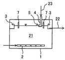
- FIG. 1 shows a configuration example of a water treatment apparatus provided with a liquid supply pipe.
- the water treatment apparatus shown in FIG. 1 has an inflow portion 2 for treated water 21 and an outflow portion 3 for treated water 22 located above the inflow portion 2, and anaerobic sludge is discharged up to the height of the outflow portion 3. It has an upward flow type anaerobic reaction tank 1 in which the treated water 21 is contained, and a liquid supply pipe 4 provided in the anaerobic reaction tank 1.
- the supply pipe 4 has an opening 5 that is positioned above the upper third region of the water 21 to be treated or the water surface in the anaerobic reaction tank 1 and that faces in the substantially horizontal direction.
- the opening 5 is provided at a position including the water surface in the anaerobic reaction tank 1.
- the outflow part 3 is formed of the overflow dam. In the drawing, the position of the water surface is indicated by a downward triangle.
- the anaerobic treatment is performed by introducing the treated water 21 into the anaerobic reaction tank 1 in an upward flow manner and bringing it into contact with the anaerobic sludge in the treated water 21.
- the anaerobic treatment in the anaerobic reaction tank 1 is performed by performing a treatment process and a liquid supply process for supplying the liquid 23 to the water 21 to be treated held in the anaerobic reaction tank 1 from the opening 5 of the supply pipe 4. It can be suitably performed.
- the water surface of the water 21 to be treated is disturbed, and the water in the substantially horizontal direction is near the water surface of the water 21 to be treated.
- a flow can be formed, whereby gas can be effectively separated from the sludge floating on the surface of the water 21 to be treated.
- the sludge that floats on the surface of the water to be treated 21 is allowed to settle, so that the sludge outflow from the anaerobic reaction tank 1 can be prevented, and the sludge concentration of the water to be treated 21 can be maintained high. 1, the anaerobic treatment is suitably performed.
- the anaerobic reaction tank 1 is provided with a partition member 7 that divides the water surface in the anaerobic reaction tank 1 into a part including the outflow part 3 and a part not including the outflow part 3, and the opening 5 of the supply pipe 4 is It is provided so that it may be located in the part which does not contain the outflow part 3.
- FIG. 7 By providing the partition member 7 in this manner, the sludge that has floated to the portion that does not include the outflow portion 3 is less likely to flow out of the outflow portion 3, and the sludge that has floated to the portion that does not include the outflow portion 3 is efficiently settled. Can do.
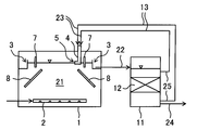
- FIGS. 2 and 3 show configuration examples in which the water treatment apparatus shown in FIG. 1 is provided with an inclined plate and a concentration tank.
- the description overlapping that of FIG. 1 is omitted.
- the upper end of the water to be treated 21 held in the anaerobic reaction tank 1 is located below the portion not including the outflow portion 3, and the lower end is the outflow portion 3.
- An inclined plate 8 is provided below the portion including the.
- a concentrating tank 11 which communicates with the outflow part 3 of the anaerobic reaction tank 1 and in which the treated water 22 of the anaerobic reaction tank 1 is concentrated.
- Transfer means 13 for transferring the concentrated sludge 25 to the supply pipe 4 is provided.
- a return flow path that connects the concentration tank 11 and the supply pipe 4 is provided as the transfer means 13.
- the treated water 22 flowing out from the anaerobic reaction tank 1 is concentrated in the concentration tank 11, and the concentrated sludge 25 obtained here is used as the liquid 23 supplied from the supply pipe 4, so that the treatment in the anaerobic reaction tank 1 is performed.
- the dilution of the water 21 can be suppressed, and the sludge concentration of the treated water 21 can be maintained high. From the concentration tank 11, the separation liquid 24 with reduced solid content flows out.
- the concentration tank 11 is a precipitation tank, and the concentrated sludge 25 stored in the lower part of the concentration tank 11 is used as the liquid 23 supplied from the supply pipe 4.
- the filtration tank 12 is provided in the concentration tank 11, and the washing wastewater generated when the washing medium is introduced from below the filtration layer 12 to wash the filtration layer 12 is handled as the concentrated sludge 25.
- washing drainage is effective to be taken out from above the filtration layer 12 depending on the configuration of the filtration layer 12 and the type (liquid, gas) of the washing medium, etc., it is effective to take out from below the filtration layer 12 There is. Therefore, it may be determined as appropriate according to the device configuration and the cleaning conditions from which the cleaning waste water is taken out.
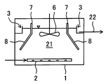
- FIG. 4 shows a configuration example of a water treatment apparatus provided with a stirring plate.
- the description which overlaps with the description of FIG. 1 is omitted.
- a stirring plate 6 is provided in the upper third region of the water to be treated 21 instead of the liquid supply pipe.
- the anaerobic treatment is performed by introducing the treated water 21 into the anaerobic reaction tank 1 in an upward flow manner and bringing it into contact with the anaerobic sludge in the treated water 21.
- a treatment step and a stirring step of stirring the water 21 to be treated by the stirring plate 6 are performed.
- the sludge floating on the water surface of the water to be treated 21 is swung to separate the gas from the sludge.
- the sludge concentration of the treated water 21 can be maintained high. Thereby, the anaerobic process in the anaerobic reaction tank 1 can be performed suitably.
- an inclined plate 8 whose upper end is connected to the partition member 7 and whose lower end is located below the portion including the outflow portion 3 is provided in the water 21 to be treated held in the anaerobic reaction tank 1. Yes.
- the inclined plate 8 is integrated with the partition member 7. Even if the inclined plate 8 is formed in this way, the sludge that floats in the water 21 to be treated is likely to gather in a portion that does not include the outflow portion 3, and the outflow of sludge from the anaerobic reaction tank 1 can be suppressed.
- anaerobic treatment of sewage primary inflow water from a sewage treatment plant
- the reaction tank was provided with an inflow portion at the bottom and an outflow portion at the top, and a liquid supply pipe was provided at a position including the water surface so that the opening was substantially horizontal.
- the reaction tank is provided with a member in which a partition member and an inclined plate are integrally formed, and the water surface is divided into a portion including the outflow portion and a portion not including the outflow portion by the partition member.
- Raw water was supplied to the reaction tank in an upward flow manner to perform anaerobic treatment.
- treated water was supplied from the supply pipe for 5 seconds once every 30 minutes to disturb the water surface.
- the daily supply of treated water from the supply pipe was 1/100 of the inflow of raw water.
- the treated water was not supplied from the supply pipe.
- Table 1 shows the processing results of Examples and Comparative Examples.
- the raw water was measured for each concentration of BOD, total COD Cr and SS, and the treated water was measured for each concentration of soluble COD Cr and organic acid.
- Each concentration of BOD, COD, SS, and organic acid was measured according to the method described in Standard Methods for the Examination of Water and Wastewater.
- the scum thickness and sedimentation sludge thickness of the reaction tank were measured at four locations in the horizontal direction of the reaction tank, and the average values were obtained.
- the present invention is generated by treatment of domestic wastewater such as sewage and human waste, process wastewater generated by sewage treatment and human waste treatment, factory wastewater generated from food factories, paper pulp factories, chemical factories, etc., livestock manure, and livestock waste It can be used for wastewater treatment.
- the water treatment apparatus of the present invention can be applied to, for example, sewage treatment plants, human waste treatment plants, various wastewater facilities, septic tanks, and the like.
Landscapes
- Life Sciences & Earth Sciences (AREA)
- Microbiology (AREA)
- Biodiversity & Conservation Biology (AREA)
- Hydrology & Water Resources (AREA)
- Engineering & Computer Science (AREA)
- Environmental & Geological Engineering (AREA)
- Water Supply & Treatment (AREA)
- Chemical & Material Sciences (AREA)
- Organic Chemistry (AREA)
- Purification Treatments By Anaerobic Or Anaerobic And Aerobic Bacteria Or Animals (AREA)
Abstract
被処理水の流入部と、流入部より上方に位置する処理水の流出部とを有し、流出部の高さまで嫌気性汚泥を含む被処理水が保持された、上向流式の嫌気性反応槽と、嫌気性反応槽に設けられた液体の供給管とを有する水処理装置であって、供給管は、嫌気性反応槽内の被処理水の上部1/3の領域または水面より上方に位置する開口を有し、開口が略水平方向に向いている。
Description
本発明は、上向流式の嫌気性反応槽を有する水処理装置と、当該嫌気性反応槽を用いた水処理方法に関する。
従来、被処理水を上向流式で嫌気性微生物を含む汚泥(嫌気性汚泥)と接触させて嫌気性処理を行う水処理装置や水処理方法が知られている。例えば、特許文献1,2には、UASB(Upflow Anaerobic Sludge Blanket:上向流嫌気性汚泥床)法により嫌気性処理を行う嫌気性反応槽を含む水処理装置が開示されており、UASB法では、嫌気性汚泥が、比較的沈降性の高い粒状に形成されたグラニュール汚泥として嫌気性反応槽内に保持されている。
嫌気性反応槽では、被処理水を嫌気性処理することによりメタンガス等が発生するため、処理に伴って汚泥の一部がガスとともに水面まで浮上する。特に上向流式の嫌気性反応槽では、反応槽内の上向きの水の流れによっても汚泥の浮上が促進される。浮上した汚泥は、そのまま放置すると嫌気性反応槽から流出し、嫌気性反応槽内での嫌気性汚泥濃度の低下を招く。これに対して、特許文献1,2に開示された水処理装置では、浮上した汚泥の沈降を促すために、嫌気性反応槽内の水面より上方にスプレー手段を設けている。しかし本発明者らが検討したところ、水面の上方からスプレーする方法では、浮上した汚泥の流出抑制効果は十分とはいえず、嫌気性反応槽内に保持された被処理水の汚泥濃度を高く維持することは難しいことが明らかになった。
本発明は前記事情に鑑みてなされたものであり、その目的は、上向流式の嫌気性反応槽を用いて嫌気性処理を行うにあたり、嫌気性反応槽からの汚泥の流出を抑え、嫌気性反応槽内に保持された被処理水の汚泥濃度を高く維持することができる水処理装置および水処理方法を提供することにある。
上記課題を解決することができた本発明の水処理装置とは、被処理水の流入部と、流入部より上方に位置する処理水の流出部とを有し、流出部の高さまで嫌気性汚泥を含む被処理水が保持された、上向流式の嫌気性反応槽と、嫌気性反応槽に設けられた液体の供給管とを有する水処理装置であって、前記供給管は、嫌気性反応槽内の被処理水の上部1/3の領域または水面より上方に位置する開口を有し、前記開口が略水平方向に向いているところに特徴を有する。本発明の水処理装置によれば、略水平方向に向いた開口を有する供給管から液体を供給することにより、嫌気性反応槽に保持された被処理水の水面近くを撹乱して、略水平方向の水の流れを形成することができ、ガスを抱き込んだ形で水面に浮上した汚泥からガスを効果的に分離できる。そのため、嫌気性反応槽内の被処理水の水面に浮上した汚泥を沈降させやすくなり、被処理水の汚泥濃度を高く維持することができる。
本発明の水処理装置は、被処理水の流入部と、流入部より上方に位置する処理水の流出部とを有し、流出部の高さまで嫌気性汚泥を含む被処理水が保持された、上向流式の嫌気性反応槽と、嫌気性反応槽内の被処理水の上部1/3の領域に設けられた撹拌板とを有するものであってもよい。この場合、嫌気性反応槽内の被処理水の上部1/3の領域に設けた撹拌板を動かすことにより、水面に浮上した汚泥を揺動して汚泥からガスを分離し、汚泥を沈降させることができ、被処理水の汚泥濃度を高く維持することができる。
供給管の開口は、嫌気性反応槽内の水面を含む位置に設けられていることが好ましい。供給管の開口が嫌気性反応槽内の水面を含む位置に設けられれば、液体を開口から吐出することにより、被処理水の水面近くを広範囲にわたって撹乱しやすくなる。
供給管から供給される液体の供給時間は、1時間当たり2秒以上20分以下であることが好ましい。液体の供給時間をこのように調整することで、液体を供給することにより汚泥の沈降を効果的に促すことができるとともに、液体の供給により汚泥が過度に細分化するのを防ぐことができ、これにより嫌気性反応槽からの汚泥の流出を好適に抑制することができる。
供給管から供給される液体の1日当たりの供給量は、被処理水の1日当たりの流入量の1/200以上1/10以下であることが好ましい。このように液体の供給量を調整することで、汚泥の細分化を抑えつつ、汚泥の沈降を促して、嫌気性反応槽からの汚泥の流出を好適に抑えることができる。
本発明の水処理装置は、嫌気性反応槽の流出部に連通し、嫌気性反応槽の処理水が濃縮される濃縮槽と、濃縮槽で得られた濃縮汚泥を供給管に移送する移送手段とをさらに有し、濃縮汚泥を前記液体として用いるものであることが好ましい。嫌気性反応槽から流出した処理水を濃縮して回収し、これを供給管から供給する液体として用いることにより、嫌気性反応槽内の被処理水の汚泥濃度を高く維持することができる。
嫌気性反応槽には、水面を、流出部を含む部分と流出部を含まない部分とに分ける仕切り部材が設けられ、供給管の開口が流出部を含まない部分またはその上方もしくは下方に位置するように設けられ、あるいは、撹拌板が流出部を含まない部分の下方に設けられることが好ましい。嫌気性反応槽に仕切り部材を設けることにより、嫌気性反応槽内の水面の流出部を含まない部分に浮上した汚泥が流出部から流出しにくくなり、流出部を含まない部分に浮上した汚泥を効率的に沈降させることができる。
嫌気性反応槽に仕切り部材が設けられる場合、嫌気性反応槽に保持された被処理水中に傾斜板が設けられることが好ましい。この場合、傾斜板は、上端が、仕切り部材に接続するか、流出部を含まない部分またはその上方もしくは下方に位置し、下端が流出部を含む部分の下方に位置することが好ましい。このように傾斜板を設けることにより、被処理水中で浮上した汚泥が流出部を含まない部分に集まりやすくなり、嫌気性反応槽からの汚泥の流出を抑えることができる。
嫌気性反応槽は、底部から水面までの高さが、嫌気性反応槽内の最大水平方向長さよりも短いことが好ましい。この場合、嫌気性反応槽は水平方向の長さに対して深さ方向の長さが短く形成されるため、供給管から液体を供給したり撹拌板によって撹拌したりして汚泥を沈降させる際、汚泥が嫌気性反応槽の底部まで沈降しやすくなる。その結果、嫌気性反応槽内でより多くの汚泥が嫌気性処理に有効に寄与しやすくなり、嫌気性反応槽全体の処理性能を高めることができる。
本発明はまた、被処理水を上向流式で嫌気性反応槽に導入し、嫌気性汚泥と接触させることにより嫌気性処理を行う嫌気性処理工程と、略水平方向に向いた開口を有し、前記開口が嫌気性反応槽内の被処理水の上部1/3の領域または水面より上方に位置するように設けられた液体の供給管から、前記開口を通じて、嫌気性反応槽内の被処理水に液体を供給する液体供給工程とを有する水処理方法も提供する。本発明の水処理方法によれば、前記のように形成された供給管の開口から液体を供給することにより、嫌気性反応槽に保持された被処理水の水面近くを撹乱して、略水平方向の水の流れを形成することができる。そのため、ガスを抱き込んだ形で水面に浮上した汚泥からガスを効果的に分離でき、これにより水面に浮上した汚泥の沈降を促し、嫌気性反応槽内の被処理水の汚泥濃度を高く維持することができる。開口は、嫌気性反応槽内の水面を含む位置に設けられていることがより好ましい。
本発明の水処理方法は、被処理水を上向流式で嫌気性反応槽に導入し、嫌気性汚泥と接触させることにより嫌気性処理する嫌気性処理工程と、嫌気性反応槽内の被処理水の上部1/3の領域に設けられた撹拌板により、被処理水を撹拌する撹拌工程とを有するものであってもよい。この場合、嫌気性反応槽に保持された被処理水の上部1/3の領域に設けた撹拌板により被処理水を撹拌することにより、水面に浮上した汚泥を揺動して汚泥からガスを分離して、汚泥を沈降させることができ、被処理水の汚泥濃度を高く維持することができる。
液体供給工程は、1時間当たり2秒以上20分以下行うことが好ましい。また、液体の1日当たりの供給量が、被処理水の1日当たりの流入量の1/200以上1/10以下であることが好ましい。このように液体供給工程を行うことにより、汚泥の細分化を抑えつつ、汚泥の沈降を促して、嫌気性反応槽からの汚泥の流出を好適に抑えることができる。
本発明の水処理方法は、嫌気性処理工程で得られた処理水を濃縮して濃縮汚泥を得る濃縮工程をさらに有し、濃縮汚泥を供給管に移送して前記液体として用いることが好ましい。嫌気性処理工程で得られた処理水を濃縮し、得られた濃縮汚泥を供給管に移送して前記液体として用いることにより、嫌気性反応槽内の被処理水の汚泥濃度を高く維持することができる。
嫌気性反応槽は処理水の流出部を有し、水面を、流出部を含む部分と流出部を含まない部分とに分ける仕切り部材が設けられることが好ましい。この場合、前記液体を、流出部を含まない部分またはその下方に供給するか、撹拌板を、流出部を含まない部分の下方に設けることが好ましい。嫌気性反応槽をこのように構成し、液体の供給や被処理水の撹拌を行うことにより、被処理水の水面の流出部を含まない部分に浮上した汚泥が流出部から流出しにくくなり、流出部を含まない部分に浮上した汚泥を効率的に沈降させることができる。さらに嫌気性反応槽に保持された被処理水中には傾斜板が設けられることが好ましく、傾斜板は、上端が、仕切り部材に接続するか、流出部を含まない部分またはその上方もしくは下方に位置し、下端が流出部を含む部分の下方に位置するように設けられることが好ましい。このように傾斜板を設けることにより、被処理水中で浮上した汚泥が流出部を含まない部分に集まりやすくなり、嫌気性反応槽からの汚泥の流出を抑えることができる。
嫌気性反応槽は、底部から水面までの高さが、嫌気性反応槽内の最大水平方向長さよりも短いことが好ましい。この場合、嫌気性反応槽は水平方向の長さに対して深さ方向の長さが短く形成されるため、液体供給工程や撹拌工程で汚泥を沈降させる際、汚泥が嫌気性反応槽の底部まで沈降しやすくなる。その結果、嫌気性反応槽内でより多くの汚泥が嫌気性処理に有効に寄与しやすくなり、嫌気性処理性能を高めることができる。
本発明の水処理装置および水処理方法によれば、略水平方向に向いた開口を有し、当該開口が嫌気性反応槽に保持された被処理水の水面近傍に位置するように設けられた供給管から、液体を供給したり、あるいは水面近傍で被処理水を撹拌することにより、嫌気性反応槽内の水面に浮上した汚泥からガスを効果的に分離できる。これにより、嫌気性反応槽内の水面に浮上した汚泥を沈降させて、被処理水の汚泥濃度を高く維持することができ、嫌気性処理を好適に行うことができる。
本発明は、嫌気性反応槽を備えた水処理装置と、嫌気性反応槽にて被処理水を嫌気性汚泥と接触させて嫌気性処理する水処理方法に関する。本発明は、嫌気性反応槽で被処理水を上向流式で嫌気性汚泥と接触させて嫌気性処理する際に、嫌気性反応槽から嫌気性汚泥が流出するのを抑え、嫌気性処理を効率的に行うことを可能とするものである。
本発明ではまず、嫌気性反応槽に被処理水を導入し、嫌気性汚泥と接触させることにより嫌気性処理を行う(嫌気性処理工程)。被処理水は、嫌気性反応槽内で処理される水を意味し、少なくとも有機物を含有していればよい。本発明において処理対象となる原水、すなわち嫌気性反応槽に導入される水としては、例えば、トイレや洗濯、風呂、台所排水等を含む下水やし尿等の生活排水が挙げられる。これ以外にも、畜産糞尿、食品工場や製紙工場等から発生する工場排水、厨房排水、これらの処理に伴い発生するプロセス排水等も対象となる。
原水の性状は特に制限されない。例えば、嫌気性処理により、あるいはそれに簡易な後処理(例えば固液分離処理等)を組み合わせることにより、河川等に放流可能なレベルまでBOD(生物学的酸素要求量)濃度を低減するためには、原水のBOD濃度は平均で30mg/L~600mg/L程度であることが好ましいが、BOD濃度がさらに高くてもよい(例えば、2,000mg/L以下)。
嫌気性反応槽には、嫌気性汚泥を含む被処理水が保持されている。嫌気性汚泥にはメタン菌等の嫌気性微生物が含まれており、嫌気性反応槽では、メタン菌等の働きにより、被処理水中の有機物がバイオガス(メタンガスや炭酸ガス)に変換されたり、資化される。嫌気性汚泥は分散状態で被処理水中に浮遊していてもよく、粒状に形成されたグラニュール汚泥として存在していてもよい。汚泥の分散状態には、汚泥がフロック状やスカム状に分散している状態も含まれる。なお、本明細書において、「嫌気性汚泥」を単に「汚泥」と称する場合がある。
嫌気性反応槽の形状は特に限定されず、代表的には、略円筒形や略直方体が挙げられる。嫌気性反応槽は、UASB法で用いられる反応槽のように鉛直方向に長い形状であってもよく、一般的な水処理の反応槽のように水平方向に長い形状であってもよい。例えば、本発明の水処理装置を浄化槽に適用する場合は、嫌気性反応槽は、軸が横方向になるように設置された略円筒形の形状とすることができる。
嫌気性反応槽は上向流式であり、被処理水の流入部と、当該流入部よりも上方に位置する処理水の流出部を有する。これにより、嫌気性反応槽には、流出部の高さまで嫌気性汚泥を含む被処理水が保持される。なお、流出部の高さとは、嫌気性反応槽から処理水が流出する最も低い位置の高さを意味し、例えば嫌気性反応槽の側面に排出部として開口が設けられ、この開口から自然流下により処理水が流出する場合は、当該開口の最も低い位置を意味する。なお流出部は、処理水が流出する部分であれば、開口に限らず、例えば、越流堰によって形成されてもよい。流出部から流出した処理水の一部は嫌気性反応槽に返送されてもよい。
嫌気性反応槽は、被処理水が上向流式で導入されることにより、嫌気性反応槽内で汚泥が嫌気性反応槽内で沈降しにくくなり、汚泥が被処理水中で浮遊状態で存在しやすくなる。これにより、被処理水と汚泥との接触効率を高めて、例えば不溶性のBOD成分であっても効率的な除去(分解)が可能となる。なお嫌気性反応槽は、流出部が流入部よりも上方に位置することで、全体で見て嫌気性反応槽内に被処理水の上向きの流れが形成されるものであればよい。
流入部は、嫌気性反応槽の下部に設けられる。具体的には、嫌気性反応槽内の被処理水の下部1/3の領域に設けられ、好ましくは下部1/4の領域に設けられ、より好ましくは下部1/5の領域に設けられる。流入部は嫌気性反応槽の底部近くに設けられてもよく、これにより嫌気性反応槽で汚泥が沈降するのを防ぎやすくなる。
流入部は、嫌気性反応槽の下部に、複数箇所設けられることが好ましい。これにより、嫌気性反応槽内での被処理水の上向きの流れを均一に形成しやすくなる。また、被処理水と汚泥との接触効率も高めやすくなる。
流入部からは、被処理水が上方向に導入されても、被処理水が下方向に導入されても、また水平方向や斜め方向に導入されてもよい。例えば、流入部において、被処理水が下方向または斜め下方向に導入されれば、汚泥が嫌気性反応槽の底部に堆積するのを防ぎやすくなる。なお汚泥中には、メタン菌等の嫌気性微生物以外に、砂等の比較的比重が大きい固形分が含まれる場合があることから、嫌気性反応槽内でこれらの固形分を比重分離させてもよい。すなわち、砂等の比較的比重の大きい固形分を嫌気性反応槽内で沈降させて、比較的比重の小さい嫌気性微生物等である汚泥を被処理水中に浮遊させることにより、砂等を嫌気性反応槽から排除しやすくしてもよい。この場合は、流入部から被処理水を上方向または斜め上方向に導入することが好ましい。また、流入部より下方に、嫌気性反応槽内で沈降した汚泥(固形分)の抜出部を設けてもよい。
嫌気性反応槽には、散気装置や撹拌装置(例えば、プロペラ式撹拌装置)等、嫌気性反応槽内を均質化する機構が設けられないことが好ましく、特に嫌気性反応槽の下部にこれらの装置が設けられないことが好ましい。散気装置や撹拌装置は被処理水の撹拌手段として機能するが、汚泥が過度に細分化されて分散性が高まることを抑制する点から、これらの装置によって被処理水が広範囲にわたって強制的に撹拌されないことが好ましい。なお、汚泥掻き寄せ機等、汚泥を細分化しない非常に低速で移動する機構は具備されていてもよい。
嫌気性反応槽に保持される被処理水の浮遊物質濃度(SS濃度)は、効率的な嫌気性処理を実現する点から、1,000mg/L以上が好ましく、5,000mg/L以上がより好ましく、10,000mg/L以上がさらに好ましい。一方、嫌気性反応槽に保持される被処理水の浮遊物質濃度の上限は、嫌気性反応槽からの汚泥の流出を勘案すると、一般的には50,000mg/L以下となる。被処理水の浮遊物質濃度は、スタンダードメソッド(Standard Methods for the Examination of Water and Wastewater)に記載の方法に基づいて求める。なお、測定用の試料は、嫌気性反応槽の流入部から流出部まで範囲の異なる高さの10箇所以上から採取する。この際、流入部から流出部までの高さ範囲でできるだけ均等間隔となるよう採取位置を調整する。これら採取した試料を等量混合し、測定に供する。
嫌気性反応槽内の被処理水の酸化還元電位(ORP)は、嫌気性細菌の活動を促進する点から、-150mV以下であることが好ましく、-200mV以下がより好ましく、-250mV以下がさらに好ましく、-300mV以下が特に好ましい。嫌気性反応槽中の被処理水の酸化還元電位の下限は特に限定されないが、例えば、-450mV以上が好ましい。
嫌気性反応槽における被処理水の上向流の流速は、汚泥(特に嫌気性細菌)の沈降を防ぎつつ、嫌気性反応槽からの汚泥の流出を抑える点から適宜定めればよい。なお、被処理水と汚泥との接触効率を高めて、できるだけ効率的な処理を実現する点から、汚泥は分散状態で嫌気性反応槽内に保持されることが好ましく、このような汚泥の流出を抑える点から、被処理水の上向流の線速度は1.5m/h未満が好ましく、1.0m/h未満がより好ましく、0.8m/h以下がさらに好ましい。被処理水の上向流をこのような線速度に調節することにより、嫌気性汚泥は、グラニュールを形成するよりもむしろ分散状態で存在しやすくなり、被処理水との接触性向上による処理水質の向上が期待できる。この際、嫌気性反応槽からの汚泥の流出を抑える点から、嫌気性反応槽の下部に汚泥の高濃度部分が形成され、上部に汚泥の低濃度部分が形成されてもよく、また汚泥の高濃度部分と低濃度部分の間には汚泥界面が形成されてもよい。被処理水の上向流の線速度の下限については、例えば、0.05m/h以上が好ましく、0.1m/h以上がより好ましく、これにより汚泥の完全な沈降を防止して、汚泥の分散状態を維持しやすくなる。被処理水の上向流の線速度は、嫌気性反応槽への被処理水の供給量を、嫌気性反応槽の水平断面積で除することにより求めることができる。嫌気性反応槽の水平断面積は、嫌気性反応槽の流入部から流出部までの高さ方向の部分に保持される被処理水の容積(嫌気性反応槽の有効容積)を、嫌気性反応槽の流入部から流出部までの高さ(水深)で除することにより求められる。
被処理水の嫌気性反応槽の滞留時間(水理学的滞留時間;HRT)は、所望の処理水性状に応じて適宜設定すればよく、例えば、1時間以上が好ましく、2時間以上がより好ましく、また24時間以下が好ましく、12時間以下がより好ましく、8時間以下がさらに好ましい。被処理水の嫌気性反応槽の滞留時間は、嫌気性反応槽への被処理水の供給量を嫌気性反応槽の有効容積で除することにより求められる。
ところで嫌気性反応槽では、被処理水を嫌気性処理することによりメタンガス等が発生するが、処理に伴って、汚泥の一部がガスを抱き込んで嫌気性反応槽内の水面まで浮上する。このように浮上した汚泥は、そのまま放置すると嫌気性反応槽から流出し、その結果、嫌気性反応槽内での嫌気性細菌濃度が低下し、処理性能の低下を招く。そこで本発明では、嫌気性反応槽に保持された被処理水の水面近傍から液体を供給している。これにより、水面に浮上した汚泥が揺動されてガスが汚泥から分離し、汚泥の沈降が促され、被処理水の汚泥濃度を高く維持することが可能となる。
液体の供給は、嫌気性反応槽に保持された被処理水の水面に浮上した汚泥を沈降させることを目的に行われる。本発明者らが検討したところ、ガスを抱き込んだ形で水面に浮上した汚泥からガスを分離するためには、水面近くの水を撹乱させることが効果的であり、特に水面近くで略水平方向の水の流れを形成することで、汚泥の下に保持されたガスが効率的に除去され、汚泥の沈降を促すことができることが分かった。そのために、本発明では、略水平方向に向き、嫌気性反応槽内の水面近傍に位置した開口を有する供給管を設けている。このように形成された供給管から液体を供給することにより、液体が供給管の開口から略水平方向に吐出され、水面近くに略水平方向の流れを形成することができる。
なお本発明者らは、水面に浮上した汚泥からガスを除去する方法として、水面の上方からスプレーする方法も検討したが、この方法では汚泥の下側に保持されたガスを効果的に除去し、また汚泥の流出を抑制することは難しいことが分かった。特に、フロック状やスカム状の汚泥(凝集作用により形成した浮遊質の汚泥集合体)の場合は、汚泥の下にガスが大量に保持されやすいため、水面の上からスプレーするよりも、水面近くで略水平方向の流れを形成することが有効となる。また、水面の上からスプレーすると、汚泥集合体が細かく破壊されて分散性が高まり、かえって汚泥の流出が起こりやすくなる場合もある。しかし、水面近くで略水平方向の流れを形成することにより、汚泥の過度の細分化が抑制され、汚泥の沈降性を高めることができる。
液体の供給管は、嫌気性反応槽内の水面近傍に液体を吐出するように開口が設けられている。供給管から吐出する液体の種類は特に限定されず、当該液体は汚泥等の固形分を含むものであってもよい。液体としては、原水、嫌気性反応槽内の被処理水、処理水、嫌気性汚泥を含む被処理水または処理水、水(水道水、工水、地下水、河川水等)、薬液等が挙げられる。なお、処理水性状を低下させず、また用役費を低減する点から、液体としては、処理水または嫌気性汚泥を含む処理水を用いることが好ましい。
供給管の開口は、嫌気性反応槽内の水面(嫌気性反応槽に保持された被処理水の水面)より下にあってもよく、上にあってもよく、水面を含む位置に設けられてもよい。供給管の開口が嫌気性反応槽内の水面より下にある場合、供給管の開口は、嫌気性反応槽に保持された被処理水の上部に位置すればよく、具体的には、嫌気性反応槽に保持された被処理水の上部1/3の領域に位置すればよい。好ましくは、供給管の開口は、嫌気性反応槽に保持された被処理水の上部1/4の領域に位置し、上部1/5の領域に位置することがより好ましい。このような位置に供給管の開口を設ければ、嫌気性反応槽に保持された被処理水の水面近くに略水平方向の流れを形成しやすくなるとともに、供給管から液体を被処理水中に吐出した際に、汚泥の細分化が抑えられ、汚泥の沈降性を高めることができる。供給管の開口は、嫌気性反応槽に保持された被処理水の水面近くに略水平方向の流れを効果的に形成する点から、開口の少なくとも一部が嫌気性反応槽内の水面から上方および下方に15cm以内(すなわち鉛直方向に30cmの範囲内)にあるように設けられることが好ましく、10cm以内がより好ましく、5cm以内がさらに好ましい。
開口は、嫌気性反応槽内の水面を含む位置に設けられることが特に好ましい。開口が嫌気性反応槽内の水面を含む位置に設けられれば、液体を開口から吐出することにより、嫌気性反応槽に保持された被処理水の水面近くを広範囲にわたって撹乱しやすくなる。すなわち、供給管から吐出された液体が、供給管の開口近くから遠くに至る広い範囲で被処理水面に着水し、これにより、広範囲にわたって被処理水の水面近くに略水平方向の流れを形成することができる。
供給管の開口は、略水平方向に向いている。これにより、供給管の開口から液体が略水平方向に吐出されやすくなり、水面近くに略水平方向の流れを形成しやすくなる。例えば、供給管の開口が水面より上にある場合は、供給管の開口が略水平方向に向いていることにより、より遠くまで液体を届けることができ、また水面に達した液体は、当該液体の有する水平方向ベクトルにより、被処理水の水面近くに略水平方向の流れを効果的に形成することができる。供給管の開口が水面下にある場合は、供給管の開口が略水平方向に向いていることにより、開口付近から被処理水中に略水平方向の流れを形成することができる。なお開口から吐出された液体は、被処理水中では水の抵抗により、吐出方向に対して横に広がるような流れを形成するため、面状に広い範囲にわたって水面近くの水を撹乱させることができる。
開口は、供給管の先端に形成されるものでもよく、供給管の途中に形成されるものでもよい。前者の場合は、供給管の端面に開口が形成されることとなり、後者の場合は、供給管の周面に開口が形成されることとなる。なお、供給管から液体を供給する際、所望の方向に液体を吐出することが容易になる点から、開口は供給管の先端に形成することが好ましい。
供給管の先端に開口が形成される場合、供給管は、先端にいくに従い内径が小さくなるように形成されていてもよく、これにより供給管の開口から液体を勢いよく吐出することができる。なお、供給管は、先端にいくに従い内径が大きくなるように形成されていてもよく、先端まで内径が変わらないように形成されていてもよい。
供給管には、開口が1つのみ設けられても、複数設けられてもよい。供給管は、途中で分岐するものであってもよく、分岐したそれぞれに開口が設けられてもよい。もちろん、供給管は分岐しないものであってもよい。開口の形状や供給管の断面形状は、円形、楕円形、卵形、多角形、不定形等、特に限定されない。
本発明では、供給管の開口が水平面に対して±20°以内の方向に向いている場合に、略水平方向に向いているものとする。なお、水平面に対する角度は、上方を正とする。供給管の開口は、好ましくは、水平面に対して±15°以内の方向に向いており、より好ましくは、水平面に対して±10°以内の方向に向いている。開口の向く角度は、開口が供給管の端面に形成される場合は、供給管の先端部分の内径中心の延在方向に基づき定める。開口が供給管の周面に形成される場合は、開口の中心を通る直線であって、供給管の内径中心と直角に交わるように引いた直線の延在方向に基づき定める。開口の中心や供給管の内径中心は、開口や供給管断面内縁の形状の重心から求める。
供給管の開口は、略水平方向に向いている限り、水平面における開口方向(水平面に投射した開口方向)は特に限定されない。例えば、嫌気性反応槽に液体の供給管の開口が1個だけ設けられる場合は、開口は、嫌気性反応槽内の水面の水平面重心に対して時計回りを正として±30°以内の方向に向いていることが好ましく、±20°以内の方向に向いていることがより好ましい。この場合、0°の方向は水面の水平面重心方向となる。このように開口を設けることにより、嫌気性反応槽に保持された被処理水の水面近くを広範囲に撹乱して、効率的に汚泥の沈降を促すことができる。嫌気性反応槽に液体の供給管の開口が2個以上設けられる場合は、開口を設ける位置に応じて、できるだけ広範囲にわたって被処理水の水面近くを撹乱できるよう、開口の向く方向を適宜設定すればよい。この場合、例えば、嫌気性反応槽内で旋回流が形成されるように、液体の供給管の開口を設けることが好ましい。なお、液体の供給管の開口が1個だけ設けられる場合であっても、嫌気性反応槽内にガイド板を設けるなどして、旋回流が形成されるようにしてもよい。
本発明では、上記のように形成された開口を有する液体の供給管から、当該開口を通じて、液体を嫌気性反応槽に保持された被処理水に供給する(液体供給工程)。液体の供給は、常時行ってもよいが、ある程度の量の汚泥が水面まで浮上した段階で液体の供給を行って、汚泥の沈降を促すことが好ましい。従って、液体の供給は間欠的に行うことが好ましい。液体の供給を間欠的に行うことにより、当該液体の使用量を減らすことができるとともに、必要以上に液体を供給することにより汚泥が細分化するのを防ぐことができる。なお、液体供給工程は、嫌気性処理工程と同時に行ってもよく、別々に行ってもよい。
汚泥の浮上の程度は、嫌気性処理により発生するガス量に応じて変化する。つまり、処理負荷や処理条件に応じて変化する。そのため液体の供給頻度を一義的に定めることは難しいが、例えば、液体の供給頻度は、24時間に1回以上が好ましく、12時間に1回以上がより好ましく、6時間に1回以上がさらに好ましく、また10分に1回以下が好ましく、20分に1回以下がより好ましい。
液体の供給時間、すなわち液体供給工程を行う時間は、1時間当たり20分以下が好ましく、15分以下がより好ましく、12分以下がさらに好ましい。液体の供給時間をこのような範囲に調整することで、液体を供給することにより汚泥が過度に細分化するのを防ぐことができる。液体を供給するポンプ等の稼働に要するエネルギーを低減する観点からは、液体の供給時間をさらに短くすることもでき、例えば1時間当たり10分以下であってもよく、8分以下であってもよく、5分以下であってもよく、3分以下であってもよい。液体の供給時間の下限については、実施例でも実証されるように、例えば1時間当たり2秒以上が好ましく、5秒以上がより好ましく、10秒以上がさらに好ましく、15秒以上がさらにより好ましい。なお、ここで説明した液体の供給時間とは、1時間当たりの平均供給時間を表し、例えば、24時間のトータルの液体供給時間を測定し、それを1時間当たりに換算することで求められる。液体の供給時間は、例えば、ポンプの稼働時間から求めることができる。
液体の1日当たりの供給量は、被処理水の1日当たりの流入量の1/200以上が好ましく、1/150以上がより好ましく、1/100以上がさらに好ましく、また1/10以下が好ましく、1/15以下がより好ましく、1/20以下がさらに好ましい。このように液体の供給量を調整することで、汚泥の細分化を抑えつつ、汚泥の沈降を促して、嫌気性反応槽からの汚泥の流出を好適に抑制することができる。液体の供給量を低減する観点からは、液体の1日当たりの供給量は被処理水の1日当たりの流入量の1/25以下であってもよく、1/30以下であってもよい。なお、被処理水の流入量は、処理水の一部を嫌気性反応槽に返送する場合は、その返送分を含まない量を意味する。
供給管からの液体の供給速度は、嫌気性反応槽内の被処理水の水面近くを効果的に撹乱させる点から、ある程度速い流速で行うことが好ましく、例えば、0.2m/s以上が好ましく、0.3m/s以上がより好ましく、0.4m/s以上がさらに好ましい。一方、あまり勢いよく液体を供給しても汚泥を細かく解砕するおそれがあることから、供給管からの液体の供給速度は、3.0m/s以下が好ましく、2.5m/s以下がより好ましく、2.0m/s以下がさらに好ましい。なお、供給管からの液体の供給速度は、供給管の開口における供給速度を意味する。
本発明では、液体の供給管から液体を供給し、これにより被処理水の水面近くを撹乱する代わりに、嫌気性反応槽に保持された被処理水の上部に撹拌板を設けて、被処理水を撹拌してもよい(撹拌工程)。嫌気性反応槽内の被処理水の上部に設けた撹拌板を動かすことにより、水面に浮上した汚泥を揺動して汚泥からガスを分離し、汚泥を沈降させることができる。
撹拌板は、略水平方向の水流を起こすように形成されていることが好ましく、例えば、撹拌羽根のように回転移動するものであってもよく、略水平方向に平行移動するものであってもよく、またフラップのように往復回転移動するものであってもよい。撹拌板の断面形状は特に限定されず、四角形等の多角形、角の丸まった多角形、楕円形、円形、不定形等、特に限定されない。
撹拌板は、嫌気性反応槽内の被処理水の上部1/3の領域に設けられ、好ましくは上部1/4の領域に設けられ、より好ましくは上部1/5の領域に設けられる。このような位置に撹拌板を設けることにより、嫌気性反応槽に保持された被処理水の水面近くに略水平方向の流れを形成しやすくなる。撹拌板はまた、少なくとも一部が水面から30cm以内に位置するように設けられることが好ましく、20cm以内がより好ましく、15cm以内がさらに好ましい。
撹拌工程は常時行ってもよいが、液体供給工程と同じように、間欠的に行うことが好ましい。撹拌工程を行う頻度は、24時間に1回以上が好ましく、12時間に1回以上がより好ましく、6時間に1回以上がさらに好ましく、また10分に1回以下が好ましく、20分に1回以下がより好ましい。撹拌工程を行う時間は、1時間当たり20分以下であることが好ましく、15分以下がより好ましく、12分以下がさらに好ましく、また1時間当たり10秒以上が好ましく、15秒以上がより好ましい。撹拌板の稼働に要するエネルギーを低減する観点からは、撹拌工程の時間をさらに短くすることもでき、例えば1時間当たり10分以下であってもよく、8分以下であってもよく、5分以下であってもよく、3分以下であってもよい。撹拌工程を行う頻度および時間に関する技術的意義は、液体供給工程の場合と同じである。撹拌工程は、嫌気性処理工程と同時に行ってもよく、別々に行ってもよい。
撹拌板の移動速度は、嫌気性反応槽内の被処理水の水面近くを効果的に撹拌する点から、0.05m/s以上が好ましく、0.10m/s以上がより好ましく、0.15m/s以上がさらに好ましい。一方、汚泥の解砕をできるだけ抑える点から、撹拌板の移動速度は、1.5m/s以下が好ましく、1.2m/s以下がより好ましく、1.0m/s以下がさらに好ましい。なお、撹拌板が回転移動や往復回転移動する場合は、回転中心と先端の中点における線速度を移動速度とする。
液体供給工程や撹拌工程では、嫌気性反応槽内の被処理水の水面近くを撹乱させることにより、水面に浮いた、特にフロック等の集合体を形成した汚泥の再沈降を促しているが、集合体を形成した汚泥は、嫌気性反応槽内でできるだけ均一に存在していることが好ましい。従って、集合体を形成した汚泥が沈降する際、嫌気性反応槽のできるだけ底部まで沈降するように嫌気性反応槽が形成されていることが好ましく、これにより、嫌気性反応槽全体の処理性能を高めることができる。この点から、嫌気性反応槽は、水深が深くなり過ぎないように形成されていることが好ましい。一方、このような状況で嫌気性反応槽の処理量を確保するためには、嫌気性反応槽の設置面積を広くとることが必要となる。従って、嫌気性反応槽は、底部から被処理水の水面までの高さが、嫌気性反応槽内の最大水平方向長さよりも短く形成されていることが好ましく、前記最大水平方向長さの1/3以下となるように形成されていることがより好ましい。このように嫌気性反応槽を形成することにより、嫌気性反応槽の処理性能と処理量の両方を高めることができる。なお、嫌気性反応槽内の最大水平方向長さとは、嫌気性反応槽内の被処理水が保持される部分(空間)で、水平方向に最大となる長さを意味する。
嫌気性反応槽には、嫌気性反応槽内の水面を、流出部を含む部分と流出部を含まない部分とに分ける仕切り部材が設けられていることが好ましい。このとき、供給管の開口は、流出部を含まない部分またはその上方もしくは下方に位置するように設けられることが好ましい。詳細には、供給管の開口は、被処理水の水面の流出部を含まない部分か、当該流出部を含まない部分の鉛直上方の水面より上の空間か、当該流出部を含まない部分の鉛直下方の被処理水中に位置するように設けられることが好ましい。そして、液体供給工程において、液体を、流出部を含まない部分またはその下方(すなわち被処理水の水面の流出部を含まない部分か当該部分の鉛直下方の被処理水中)に供給することが好ましい。被処理水中に撹拌板を設ける場合は、撹拌板は、前記流出部を含まない部分の下方(すなわち流出部を含まない部分の鉛直下方の被処理水中)に設けられることが好ましい。このように嫌気性反応槽に仕切り部材を設けることにより、嫌気性反応槽に保持された被処理水の水面の流出部を含まない部分に浮上した汚泥が流出部から流出しにくくなり、流出部を含まない部分に浮上した汚泥を効率的に沈降させることができる。
仕切り部材は、供給管の開口よりも下まで延在するように設けられることが好ましい(特に、供給管の開口が水面を含む位置かそれより下方に位置する場合)。このように仕切り部材を設けることにより、流出部を含まない部分に浮上した汚泥を効率的に沈降させることができる。
仕切り部材は、嫌気性反応槽内の水面において連続的に設けられ、両端が嫌気性反応槽の内面に接続していることが好ましいが、一部が断続的に設けられていてもよい。なお、水面における仕切り部材の断続部分の長さは、仕切り部材の延在部分の長さの20%以下であることが好ましく、10%以下であることがより好ましく、5%以下がさらに好ましい。ここで、仕切り部材の延在部分の長さは、仕切り部材が被処理水の水面より上に出ている部分の長さを意味し、仕切り部材の断続部分の長さは、仕切り部材が断続している部分の最短距離(隣接する延在部分の端部間距離や延在部分の端部と嫌気性反応槽内面との間の距離)の総和を意味する。
仕切り部材は、流出部を含む部分よりも流出部を含まない部分の方が広くなるように設けられることが好ましい。より好ましくは、仕切り部材は、流出部を含まない部分の面積が流出部を含む部分の面積よりも1.5倍以上広くなるように設けられ、さらに好ましくは、2倍以上広くなるように設けられる。特に、後述するような傾斜板が設けられない場合は、このように仕切り部材が設けられることが好ましい。なお、仕切り部材が断続的に設けられる場合は、仕切り部材の断続部分を最短距離で結ぶことにより、流出部を含む部分と流出部を含まない部分を区分するものとする。
嫌気性反応槽では、被処理水中で浮上した汚泥が、流出部を含まない部分に集まるように形成されていることが好ましい。この点から、嫌気性反応槽の被処理水中には傾斜板が設けられることが好ましい。傾斜板は少なくとも一部が傾斜していればよく、傾斜部分は、鉛直断面で見て直線状に傾斜していてもよく、曲線状に傾斜していてもよく、またこれらの組み合わせでもよい。傾斜板は、上端が、仕切り部材に接続するか、流出部を含まない部分またはその上方もしくは下方に位置し、下端が流出部を含む部分の下方に位置するように設けられている。なお、傾斜板の上端が仕切り部材に接続する場合は、傾斜板と仕切り部材が一体的に形成されることとなる。傾斜板の上端が流出部を含まない部分の上方に位置する場合は、傾斜板の上端が流出部を含まない部分の鉛直上方の水面より上の空間に位置することとなり、傾斜板の上端が流出部を含まない部分の下方に位置する場合は、傾斜板の上端が流出部を含まない部分の鉛直下方の被処理水中に位置することとなる。傾斜板の上端が流出部を含まない部分に位置する場合は、傾斜板が仕切り部材の下方を横切り、傾斜板の上端が流出部を含まない部分に位置するように設けられることが好ましい。一方、傾斜板の下端は、流出部を含む部分の鉛直下方の被処理水中に位置する。このように傾斜板を設けることにより、流出部を含む部分の下方から汚泥が浮上する場合でも、汚泥が傾斜板に沿って浮上することで、被処理水の水面の流出部を含まない部分に浮上させることができる。その結果、浮上した汚泥が流出部を含まない部分に集まりやすくなり、また嫌気性反応槽からの汚泥の流出を抑えることができる。
嫌気性反応槽の後段には、濃縮槽が設けられることが好ましい。本発明では、嫌気性反応槽に液体の供給管や撹拌板を設けることにより、嫌気性反応槽内の被処理水の水面に浮上した汚泥を再沈降させて、嫌気性反応槽からの汚泥の流出を極力抑えるようにしているが、汚泥の一部は、処理水流に伴って嫌気性反応槽から流出してしまう場合がある。特に、嫌気性汚泥は比較的粒径が小さく、分散性も高いことから、その一部が嫌気性反応槽から流出しやすい。そのため、嫌気性反応槽からの流出水に含まれる汚泥を回収するために、嫌気性反応槽の後段に濃縮槽を設けることが好ましい。これにより、嫌気性処理工程で得られた処理水を濃縮して濃縮汚泥を得ることができる(濃縮工程)。また、これにより得られる分離液は固形分濃度が低減されたものとなるため、最終的に得られる処理水質の改善も期待できる。
濃縮槽は、嫌気性反応槽の流出部に連通して設けられ、嫌気性反応槽の処理水が流入し、濃縮される。濃縮槽は、任意の固液分離手段により、処理水に含まれる汚泥を濃縮できるものであれば特に限定されず、例えば、沈殿分離、ろ過分離、膜分離、遠心分離等の分離手段を採用できる。これらの分離手段は、組み合わせて用いてもよい。ろ過分離や膜分離の場合は、洗浄や逆洗の際に発生した廃水を濃縮汚泥として用いることができる。
濃縮槽では、固形分濃度が高められた濃縮汚泥と、固形分濃度が低下した分離液とが得られる。このようにして得られた濃縮汚泥は嫌気性反応槽に返送することが好ましく、これにより嫌気性反応槽の汚泥濃度を高く維持し、嫌気性反応槽における処理性能を高めることができる。
濃縮汚泥は、液体の供給管に移送して、当該供給管から供給する液体として用いることが好ましい。これにより、供給管から液体を供給しても、嫌気性反応槽内の被処理水の希薄化を抑え、被処理水の汚泥濃度を高く維持することができる。従って、本発明の水処理装置には、濃縮汚泥を供給管に移送する移送手段が設けられることが好ましい。具体的には、濃縮槽と供給管とを繋ぐ返送流路が設けられ、返送流路にはポンプ等が設けられることが好ましい。
次に、本発明の水処理装置の構成例について、図面を参照して説明する。なお、本発明は、図面に示した実施態様に限定されない。
図1には、液体の供給管を備えた水処理装置の構成例を示した。図1に示した水処理装置は、被処理水21の流入部2と、流入部2より上方に位置する処理水22の流出部3とを有し、流出部3の高さまで嫌気性汚泥を含む被処理水21が保持された、上向流式の嫌気性反応槽1と、嫌気性反応槽1に設けられた液体の供給管4とを有する。供給管4は、被処理水21の上部1/3の領域または嫌気性反応槽1内の水面より上方に位置し、略水平方向に向いた開口5を有する。図1では、開口5が、嫌気性反応槽1内の水面を含む位置に設けられている。また、流出部3は、越流堰により形成されている。なお図面において、水面の位置は下向きの三角で示されている。
図1に示した水処理装置では、被処理水21を上向流式で嫌気性反応槽1に導入し、被処理水21中の嫌気性汚泥と接触させることにより嫌気性処理を行う嫌気性処理工程と、供給管4の開口5から、嫌気性反応槽1に保持された被処理水21に液体23を供給する液体供給工程とを行うことにより、嫌気性反応槽1での嫌気処理を好適に行うことができる。すなわち、略水平方向に向いた開口5を有する供給管4から液体23を供給することにより、被処理水21の水面近くを撹乱して、被処理水21の水面近くに略水平方向の水の流れを形成することができ、これにより、被処理水21の水面に浮上した汚泥からガスを効果的に分離することができる。その結果、被処理水21の水面に浮上した汚泥を沈降させて、嫌気性反応槽1からの汚泥の流出を防ぎ、被処理水21の汚泥濃度を高く維持することができ、嫌気性反応槽1で嫌気性処理が好適に行われるようになる。
嫌気性反応槽1には、嫌気性反応槽1内の水面を、流出部3を含む部分と流出部3を含まない部分とに分ける仕切り部材7が設けられ、供給管4の開口5が、流出部3を含まない部分に位置するように設けられている。このように仕切り部材7を設けることにより、流出部3を含まない部分に浮上した汚泥が流出部3から流出しにくくなり、流出部3を含まない部分に浮上した汚泥を効率的に沈降させることができる。
図2および図3には、図1に示した水処理装置に傾斜板と濃縮槽を設けた構成例を示した。なお、図2および図3に水処理装置に関する下記の説明では、図1の説明と重複する説明を省く。
図2および図3に示した水処理装置には、嫌気性反応槽1に保持された被処理水21中に、上端が流出部3を含まない部分の下方に位置し、下端が流出部3を含む部分の下方に位置する傾斜板8が設けられている。傾斜板8を設けることにより、被処理水21中で浮上した汚泥が流出部3を含まない部分に集まりやすくなり、嫌気性反応槽1からの汚泥の流出を抑えることができる。
図2および図3では、嫌気性反応槽1の流出部3に連通して、嫌気性反応槽1の処理水22が濃縮される濃縮槽11が設けられ、さらに、濃縮槽11で得られた濃縮汚泥25を供給管4に移送する移送手段13が設けられている。図では、移送手段13として、濃縮槽11と供給管4とを繋ぐ返送流路が設けられている。このように構成することにより、濃縮汚泥25を、供給管4から供給する液体23として用いることができる。嫌気性反応槽1から流出した処理水22を濃縮槽11で濃縮し、ここで得られた濃縮汚泥25を供給管4から供給する液体23として用いることにより、嫌気性反応槽1内の被処理水21の希薄化を抑え、被処理水21の汚泥濃度を高く維持することができる。濃縮槽11からは、固形分濃度が低減された分離液24が流出する。
なお図2では、濃縮槽11が沈殿槽となっており、濃縮槽11の下部に貯まった濃縮汚泥25を、供給管4から供給する液体23として用いている。図3では、濃縮槽11にろ過層12が設けられており、ろ過層12の下から洗浄媒体を導入してろ過層12を洗浄する際に発生する洗浄排水を濃縮汚泥25として扱う。洗浄排水は、ろ過層12の構成や洗浄媒体の種類(液体、気体)等に応じて、ろ過層12の上方から取り出すことが有効な場合と、ろ過層12の下方から取り出すことが有効な場合とがある。従って、どちらから洗浄排水を取り出すのかは、装置構成や洗浄条件に応じて適宜決めればよい。
図4には、撹拌板を備えた水処理装置の構成例を示した。なお、図4に示した水処理装置に関する下記の説明では、図1の説明と重複する説明を省く。
図4に示した水処理装置では、液体の供給管の代わりに、被処理水21の上部1/3の領域に撹拌板6が設けられている。図4に示した水処理装置では、被処理水21を上向流式で嫌気性反応槽1に導入し、被処理水21中の嫌気性汚泥と接触させることにより嫌気性処理を行う嫌気性処理工程と、撹拌板6により被処理水21を撹拌する撹拌工程とを行う。図4に示した水処理装置では、被処理水21の上部に設けた撹拌板6を動かすことにより、被処理水21の水面に浮上した汚泥を揺動して汚泥からガスを分離し、汚泥を沈降させることができ、被処理水21の汚泥濃度を高く維持することができる。これにより、嫌気性反応槽1での嫌気処理を好適に行うことができる。
図4ではまた、嫌気性反応槽1に保持された被処理水21中に、上端が仕切り部材7に接続し、下端が流出部3を含む部分の下方に位置する傾斜板8が設けられている。図4では、傾斜板8は、仕切り部材7と一体化されている。このように傾斜板8を形成しても、被処理水21中で浮上した汚泥が流出部3を含まない部分に集まりやすくなり、嫌気性反応槽1からの汚泥の流出を抑えることができる。
本願は、2015年3月27日に出願された日本国特許出願第2015-067132号に基づく優先権の利益を主張するものである。2015年3月27日に出願された日本国特許出願第2015-067132号の明細書の全内容が、本願に参考のために援用される。
以下に、実施例を示すことにより本発明を更に詳細に説明するが、本発明の範囲はこれらに限定されるものではない。
有効容積9m3、水深2mの嫌気性反応槽を用いて、下水(下水処理場の初沈流入水)の嫌気性処理を行った。反応槽は、底部に流入部が設けられ、上部に流出部が設けられ、液体の供給管が、水面を含む位置に開口が略水平方向に向くように設けられていた。また反応槽には、仕切り部材と傾斜板が一体形成された部材が設けられ、仕切り部材によって水面が流出部を含む部分と流出部を含まない部分とに分けられていた。原水を上向流式で反応槽に供給して嫌気性処理を行った。実施例では、30分に1回、供給管から処理水を5秒間供給し、水面を撹乱した。供給管からの処理水の1日当たりの供給量は、原水の流入量の1/100とした。比較例では、供給管からの処理水の供給は行わなかった。
実施例と比較例の処理結果を表1に示す。原水は、BOD、全CODCr、SSの各濃度を測定し、処理水は溶解性CODCr、有機酸の各濃度を測定した。BOD、COD、SS、有機酸の各濃度はスタンダードメソッド(Standard Methods for the Examination of Water and Wastewater)に記載の方法に従い測定した。また、反応槽のスカム厚と沈降汚泥厚を、反応槽の水平方向4ヶ所について測定し、その平均値を求めた。
実施例と比較例では原水性状に大差はなく、いずれも嫌気性処理により原水中のCODが分解されて低分子化されたが、処理水質には大きな差が見られた。実施例では、水面の撹乱操作を行うことにより、反応層内で汚泥が浮上してスカム形成することが抑えられた。そのため、反応槽からの汚泥の流出が抑えられ、反応槽内で嫌気性処理に有効に寄与する汚泥濃度を高く維持することができた。その結果、嫌気性処理を順調に行うことができ、原水中のCODが有機酸を経てメタンガスと二酸化炭素までスムーズに分解され、有機酸の蓄積が認められず、処理水COD濃度も低くすることができた。一方、比較例では水面の撹乱操作を行わなかったため、反応槽内で汚泥が浮上してスカムが形成され、反応槽からの汚泥の流出が高濃度で認められた。比較例では、原水中のCODが分解して生成した有機酸のさらなる分解(メタンガスと二酸化炭素への分解)がスムーズに進行せず、有機酸濃度の上昇が認められ、処理水COD濃度が実施例の倍以上の濃度となった。

本発明は、下水やし尿等生活排水、下水処理やし尿処理に伴い発生するプロセス排水、食品工場、紙パルプ工場、化学工場等から発生する工場排水、家畜糞尿、畜産廃棄物の処理により発生する排水等の処理に用いることができる。本発明の水処理装置は、例えば、下水処理場、し尿処理場、各種廃水施設、浄化槽等に適用することができる。
1:嫌気性反応槽
2:流入部
3:流出部
4:供給管
5:開口
6:撹拌板
7:仕切り部材
8:傾斜板
11:濃縮槽
12:ろ過層
13:濃縮汚泥の移送手段
21:嫌気性反応槽内の被処理水
22:処理水
23:液体
24:分離液
25:濃縮汚泥
2:流入部
3:流出部
4:供給管
5:開口
6:撹拌板
7:仕切り部材
8:傾斜板
11:濃縮槽
12:ろ過層
13:濃縮汚泥の移送手段
21:嫌気性反応槽内の被処理水
22:処理水
23:液体
24:分離液
25:濃縮汚泥
Claims (20)
- 被処理水の流入部と、前記流入部より上方に位置する処理水の流出部とを有し、前記流出部の高さまで嫌気性汚泥を含む被処理水が保持された、上向流式の嫌気性反応槽と、
前記嫌気性反応槽に設けられた液体の供給管とを有する水処理装置であって、
前記供給管は、前記嫌気性反応槽内の被処理水の上部1/3の領域または水面より上方に位置する開口を有し、前記開口が略水平方向に向いていることを特徴とする水処理装置。 - 前記開口は、前記嫌気性反応槽内の水面を含む位置に設けられている請求項1に記載の水処理装置。
- 前記供給管から供給される液体の供給時間は、1時間当たり2秒以上20分以下である請求項1または2に記載の水処理装置。
- 前記供給管から供給される液体の1日当たりの供給量は、前記被処理水の1日当たりの流入量の1/200以上1/10以下である請求項1~3のいずれか一項に記載の水処理装置。
- 前記水処理装置は、前記嫌気性反応槽の流出部に連通し、前記嫌気性反応槽の処理水が濃縮される濃縮槽と、
前記濃縮槽で得られた濃縮汚泥を前記供給管に移送する移送手段とを、さらに有し、
前記濃縮汚泥を前記液体として用いる請求項1~4のいずれか一項に記載の水処理装置。 - 前記嫌気性反応槽には、水面を前記流出部を含む部分と前記流出部を含まない部分とに分ける仕切り部材が設けられ、
前記供給管の開口は、前記流出部を含まない部分またはその上方もしくは下方に位置するように設けられている請求項1~5のいずれか一項に記載の水処理装置。 - 被処理水の流入部と、前記流入部より上方に位置する処理水の流出部とを有し、前記流出部の高さまで嫌気性汚泥を含む被処理水が保持された、上向流式の嫌気性反応槽と、
前記嫌気性反応槽内の被処理水の上部1/3の領域に設けられた撹拌板とを有することを特徴とする水処理装置。 - 前記嫌気性反応槽には、水面を前記流出部を含む部分と前記流出部を含まない部分とに分ける仕切り部材が設けられ、
前記撹拌板は、前記流出部を含まない部分の下方に設けられている請求項7に記載の水処理装置。 - 前記嫌気性反応槽に保持された被処理水中に傾斜板が設けられ、
前記傾斜板は、上端が、前記仕切り部材に接続するか、前記流出部を含まない部分またはその上方もしくは下方に位置し、下端が前記流出部を含む部分の下方に位置する請求項6または8に記載の水処理装置。 - 前記嫌気性反応槽は、底部から水面までの高さが、前記嫌気性反応槽内の最大水平方向長さよりも短い請求項1~9のいずれか一項に記載の水処理装置。
- 被処理水を上向流式で嫌気性反応槽に導入し、嫌気性汚泥と接触させることにより嫌気性処理を行う嫌気性処理工程と、
略水平方向に向いた開口を有し、前記開口が前記嫌気性反応槽内の被処理水の上部1/3の領域または水面より上方に位置するように設けられた液体の供給管から、前記開口を通じて、前記嫌気性反応槽内の被処理水に液体を供給する液体供給工程とを有することを特徴とする水処理方法。 - 前記開口は、前記嫌気性反応槽内の水面を含む位置に設けられている請求項11に記載の水処理方法。
- 前記液体供給工程を、1時間当たり2秒以上20分以下行う請求項11または12に記載の水処理方法。
- 前記液体の1日当たりの供給量が、前記被処理水の1日当たりの流入量の1/200以上1/10以下である請求項11~13のいずれか一項に記載の水処理方法。
- 前記嫌気性処理工程で得られた処理水を濃縮して濃縮汚泥を得る濃縮工程をさらに有し、
前記濃縮汚泥を、前記供給管に移送して、前記液体として用いる請求項11~14のいずれか一項に記載の水処理方法。 - 前記嫌気性反応槽は処理水の流出部を有し、水面を前記流出部を含む部分と前記流出部を含まない部分とに分ける仕切り部材が設けられ、
前記液体供給工程において、前記液体を、前記流出部を含まない部分またはその下方に供給する請求項11~15のいずれか一項に記載の水処理方法。 - 被処理水を上向流式で嫌気性反応槽に導入し、嫌気性汚泥と接触させることにより嫌気性処理する嫌気性処理工程と、
前記嫌気性反応槽内の被処理水の上部1/3の領域に設けられた撹拌板により、被処理水を撹拌する撹拌工程とを有することを特徴とする水処理方法。 - 前記嫌気性反応槽は処理水の流出部を有し、水面を前記流出部を含む部分と前記流出部を含まない部分とに分ける仕切り部材が設けられ、
前記撹拌板は、前記流出部を含まない部分の下方に設けられている請求項17に記載の水処理方法。 - 前記嫌気性反応槽に保持された被処理水中に傾斜板が設けられ、
前記傾斜板は、上端が、前記仕切り部材に接続するか、前記流出部を含まない部分またはその上方もしくは下方に位置し、下端が前記流出部を含む部分の下方に位置する請求項16または18に記載の水処理方法。 - 前記嫌気性反応槽は、底部から水面までの高さが、前記嫌気性反応槽内の最大水平方向長さよりも短い請求項11~19のいずれか一項に記載の水処理方法。
Priority Applications (2)
| Application Number | Priority Date | Filing Date | Title |
|---|---|---|---|
| MYPI2017702890A MY182787A (en) | 2015-03-27 | 2016-03-24 | Water treatment apparatus and process for treating water |
| JP2017509866A JP6640837B2 (ja) | 2015-03-27 | 2016-03-24 | 水処理装置および水処理方法 |
Applications Claiming Priority (2)
| Application Number | Priority Date | Filing Date | Title |
|---|---|---|---|
| JP2015067132 | 2015-03-27 | ||
| JP2015-067132 | 2015-03-27 |
Publications (1)
| Publication Number | Publication Date |
|---|---|
| WO2016158673A1 true WO2016158673A1 (ja) | 2016-10-06 |
Family
ID=57007103
Family Applications (1)
| Application Number | Title | Priority Date | Filing Date |
|---|---|---|---|
| PCT/JP2016/059411 Ceased WO2016158673A1 (ja) | 2015-03-27 | 2016-03-24 | 水処理装置および水処理方法 |
Country Status (3)
| Country | Link |
|---|---|
| JP (1) | JP6640837B2 (ja) |
| MY (1) | MY182787A (ja) |
| WO (1) | WO2016158673A1 (ja) |
Cited By (2)
| Publication number | Priority date | Publication date | Assignee | Title |
|---|---|---|---|---|
| JP2020082045A (ja) * | 2018-11-30 | 2020-06-04 | 住友重機械工業株式会社 | 嫌気処理システム |
| CN111908711A (zh) * | 2020-07-13 | 2020-11-10 | 中徽生态环境有限公司 | 一种分段式生化混合处理水体生态修复方法 |
Citations (9)
| Publication number | Priority date | Publication date | Assignee | Title |
|---|---|---|---|---|
| JPS60168597A (ja) * | 1984-02-10 | 1985-09-02 | Matsushita Electric Ind Co Ltd | メタン発酵装置 |
| JPH02273598A (ja) * | 1989-04-14 | 1990-11-08 | Taisei Corp | 上向流式嫌気性排水処理装置 |
| JPH06182382A (ja) * | 1992-12-17 | 1994-07-05 | Kurita Water Ind Ltd | 嫌気性処理方法および装置 |
| JPH07290088A (ja) * | 1994-04-26 | 1995-11-07 | Mitsubishi Kakoki Kaisha Ltd | 有機性廃水の生物学的脱窒方法 |
| JPH0866694A (ja) * | 1994-08-29 | 1996-03-12 | Hitachi Zosen Corp | メタン発酵方法 |
| JP2003311292A (ja) * | 2002-04-24 | 2003-11-05 | Kurita Water Ind Ltd | 嫌気性水処理装置 |
| JP2005205327A (ja) * | 2004-01-23 | 2005-08-04 | Kajima Corp | 嫌気性消化槽内の浮上夾雑物の除去方法及び装置 |
| JP2008036529A (ja) * | 2006-08-04 | 2008-02-21 | National Institute For Environmental Studies | メタン発酵による排水処理方法及び装置 |
| JP2014024032A (ja) * | 2012-07-27 | 2014-02-06 | Japan Organo Co Ltd | 嫌気性生物処理方法および嫌気性生物処理装置 |
-
2016
- 2016-03-24 MY MYPI2017702890A patent/MY182787A/en unknown
- 2016-03-24 JP JP2017509866A patent/JP6640837B2/ja active Active
- 2016-03-24 WO PCT/JP2016/059411 patent/WO2016158673A1/ja not_active Ceased
Patent Citations (9)
| Publication number | Priority date | Publication date | Assignee | Title |
|---|---|---|---|---|
| JPS60168597A (ja) * | 1984-02-10 | 1985-09-02 | Matsushita Electric Ind Co Ltd | メタン発酵装置 |
| JPH02273598A (ja) * | 1989-04-14 | 1990-11-08 | Taisei Corp | 上向流式嫌気性排水処理装置 |
| JPH06182382A (ja) * | 1992-12-17 | 1994-07-05 | Kurita Water Ind Ltd | 嫌気性処理方法および装置 |
| JPH07290088A (ja) * | 1994-04-26 | 1995-11-07 | Mitsubishi Kakoki Kaisha Ltd | 有機性廃水の生物学的脱窒方法 |
| JPH0866694A (ja) * | 1994-08-29 | 1996-03-12 | Hitachi Zosen Corp | メタン発酵方法 |
| JP2003311292A (ja) * | 2002-04-24 | 2003-11-05 | Kurita Water Ind Ltd | 嫌気性水処理装置 |
| JP2005205327A (ja) * | 2004-01-23 | 2005-08-04 | Kajima Corp | 嫌気性消化槽内の浮上夾雑物の除去方法及び装置 |
| JP2008036529A (ja) * | 2006-08-04 | 2008-02-21 | National Institute For Environmental Studies | メタン発酵による排水処理方法及び装置 |
| JP2014024032A (ja) * | 2012-07-27 | 2014-02-06 | Japan Organo Co Ltd | 嫌気性生物処理方法および嫌気性生物処理装置 |
Cited By (3)
| Publication number | Priority date | Publication date | Assignee | Title |
|---|---|---|---|---|
| JP2020082045A (ja) * | 2018-11-30 | 2020-06-04 | 住友重機械工業株式会社 | 嫌気処理システム |
| JP7130537B2 (ja) | 2018-11-30 | 2022-09-05 | 住友重機械工業株式会社 | 嫌気処理システム |
| CN111908711A (zh) * | 2020-07-13 | 2020-11-10 | 中徽生态环境有限公司 | 一种分段式生化混合处理水体生态修复方法 |
Also Published As
| Publication number | Publication date |
|---|---|
| MY182787A (en) | 2021-02-05 |
| JPWO2016158673A1 (ja) | 2018-01-25 |
| JP6640837B2 (ja) | 2020-02-05 |
Similar Documents
| Publication | Publication Date | Title |
|---|---|---|
| EP2508483B1 (en) | Waste water treatment equipment | |
| CN209759191U (zh) | 一种电絮凝协同臭氧纳米气泡气浮处理畜禽废水的装置 | |
| KR100808289B1 (ko) | 스크류형 경사판을 갖는 폐수설비의 침전조 | |
| CN104529092B (zh) | 一种腈纶废水处理系统 | |
| CN103922527B (zh) | 一体化污水深度处理装置及其工艺 | |
| CN104445836B (zh) | 高浓度沥青废水处理方法和装置 | |
| CN104529090B (zh) | 一种造纸废水深度处理系统 | |
| CN104787970A (zh) | 一种水杨酸废水处理系统 | |
| CN105692814B (zh) | 一种高浓度悬浮物电絮凝与絮体分离沉淀一体化处理装置 | |
| CN108658192A (zh) | 一种高效混凝沉淀装置及方法 | |
| CN204702591U (zh) | 污水处理系统 | |
| CA2931328A1 (en) | Enhanced treatment shaft | |
| CN110678244A (zh) | 沉淀和漂浮分离工序一体化高效率沉淀漂浮系统以及其驱动方法 | |
| CN104193041A (zh) | 一种玉石加工废水的处理方法 | |
| CN109133510A (zh) | 高浓度大蒜废水处理装置 | |
| JP6640837B2 (ja) | 水処理装置および水処理方法 | |
| CN204384990U (zh) | 一种循环冷却水石灰软化澄清过滤处理系统 | |
| CN110407417A (zh) | 一种泵站前池水质高效处理一体设备 | |
| KR100646042B1 (ko) | 스크류형 경사판을 갖는 폐수설비의 침전조 | |
| CN210419541U (zh) | 用于底泥余水处理设备的预处理系统 | |
| CN217757087U (zh) | 污水处理池 | |
| CN105948332A (zh) | 刀削废液处理装置与方法 | |
| CN105330105B (zh) | 无机‑有机‑微生物絮凝一体化装置 | |
| CN102757140A (zh) | PFS混凝与Fenton组合处理工业污水的方法 | |
| CN102863063B (zh) | 一种高密度絮凝澄清污水处理装置 |
Legal Events
| Date | Code | Title | Description |
|---|---|---|---|
| 121 | Ep: the epo has been informed by wipo that ep was designated in this application |
Ref document number: 16772554 Country of ref document: EP Kind code of ref document: A1 |
|
| ENP | Entry into the national phase |
Ref document number: 2017509866 Country of ref document: JP Kind code of ref document: A |
|
| NENP | Non-entry into the national phase |
Ref country code: DE |
|
| 122 | Ep: pct application non-entry in european phase |
Ref document number: 16772554 Country of ref document: EP Kind code of ref document: A1 |