WO2016158535A1 - ユーザ端末、無線基地局及び無線通信方法 - Google Patents
ユーザ端末、無線基地局及び無線通信方法 Download PDFInfo
- Publication number
- WO2016158535A1 WO2016158535A1 PCT/JP2016/058867 JP2016058867W WO2016158535A1 WO 2016158535 A1 WO2016158535 A1 WO 2016158535A1 JP 2016058867 W JP2016058867 W JP 2016058867W WO 2016158535 A1 WO2016158535 A1 WO 2016158535A1
- Authority
- WO
- WIPO (PCT)
- Prior art keywords
- phr
- user terminal
- information
- unit
- cell group
- Prior art date
Links
Images


Classifications
-
- H—ELECTRICITY
- H04—ELECTRIC COMMUNICATION TECHNIQUE
- H04W—WIRELESS COMMUNICATION NETWORKS
- H04W52/00—Power management, e.g. TPC [Transmission Power Control], power saving or power classes
- H04W52/04—TPC
- H04W52/30—TPC using constraints in the total amount of available transmission power
- H04W52/36—TPC using constraints in the total amount of available transmission power with a discrete range or set of values, e.g. step size, ramping or offsets
- H04W52/365—Power headroom reporting
-
- H—ELECTRICITY
- H04—ELECTRIC COMMUNICATION TECHNIQUE
- H04W—WIRELESS COMMUNICATION NETWORKS
- H04W16/00—Network planning, e.g. coverage or traffic planning tools; Network deployment, e.g. resource partitioning or cells structures
- H04W16/02—Resource partitioning among network components, e.g. reuse partitioning
-
- H—ELECTRICITY
- H04—ELECTRIC COMMUNICATION TECHNIQUE
- H04W—WIRELESS COMMUNICATION NETWORKS
- H04W52/00—Power management, e.g. TPC [Transmission Power Control], power saving or power classes
- H04W52/04—TPC
- H04W52/06—TPC algorithms
- H04W52/14—Separate analysis of uplink or downlink
- H04W52/146—Uplink power control
-
- H—ELECTRICITY
- H04—ELECTRIC COMMUNICATION TECHNIQUE
- H04W—WIRELESS COMMUNICATION NETWORKS
- H04W52/00—Power management, e.g. TPC [Transmission Power Control], power saving or power classes
- H04W52/04—TPC
- H04W52/30—TPC using constraints in the total amount of available transmission power
- H04W52/34—TPC management, i.e. sharing limited amount of power among users or channels or data types, e.g. cell loading
-
- H—ELECTRICITY
- H04—ELECTRIC COMMUNICATION TECHNIQUE
- H04W—WIRELESS COMMUNICATION NETWORKS
- H04W72/00—Local resource management
- H04W72/04—Wireless resource allocation
-
- H—ELECTRICITY
- H04—ELECTRIC COMMUNICATION TECHNIQUE
- H04W—WIRELESS COMMUNICATION NETWORKS
- H04W72/00—Local resource management
- H04W72/04—Wireless resource allocation
- H04W72/044—Wireless resource allocation based on the type of the allocated resource
- H04W72/0453—Resources in frequency domain, e.g. a carrier in FDMA
-
- H—ELECTRICITY
- H04—ELECTRIC COMMUNICATION TECHNIQUE
- H04W—WIRELESS COMMUNICATION NETWORKS
- H04W72/00—Local resource management
- H04W72/20—Control channels or signalling for resource management
- H04W72/23—Control channels or signalling for resource management in the downlink direction of a wireless link, i.e. towards a terminal
Definitions
- the present invention relates to a user terminal, a radio base station, and a radio communication method in a next-generation mobile communication system.
- LTE Long Term Evolution
- Non-Patent Document 1 a LTE successor system (also referred to as LTE-A) called LTE Advanced has been studied for the purpose of further broadbanding and speeding up from LTE, and LTE Rel. It is specified as 10-12.
- LTE Rel One of the 10 to 12 broadband technologies is carrier aggregation (CA).
- CA carrier aggregation
- CC component carrier
- LTE Rel LTE Rel. This corresponds to 8 system bands.
- a user terminal transmits information about uplink surplus transmission power (PH: Power Headroom) for each serving cell to a network side device (for example, a radio base station (eNB)). Report).
- the radio base station can dynamically control the uplink transmission power of the user terminal based on the PHR.
- E-UTRA Evolved Universal Terrestrial Radio Access
- E-UTRAN Evolved Universal Terrestrial Radio Access Network
- the number of CCs that can be set per user terminal is limited to a maximum of five.
- the carrier aggregation in which the number of settable CCs is 6 or more may be referred to as, for example, extended CA.
- the number of CCs that can be set in the user terminal is expanded to 6 or more (for example, 32), it becomes difficult to apply the PHR usage method in the existing system (Rel. 10 to 12) as it is.
- CA of 5 CC or less is assumed. Therefore, when CA of 6 CC or more is applied, information regarding PH for each CC may not be notified to the radio base station at an appropriate timing. For this reason, there is a possibility that the radio base station cannot appropriately control the uplink transmission power of the user terminal.
- the present invention has been made in view of such a point, and even when the number of component carriers that can be set in a user terminal is expanded from an existing system, a user terminal and a radio base station that can appropriately perform communication It is another object of the present invention to provide a wireless communication method.
- the user terminal which concerns on 1 aspect of this invention is a user terminal which can communicate using a some component carrier (CC: Component Carrier), Comprising: For each CC which comprises a predetermined cell group among activated CC A generating unit that generates PHR (Power Headroom Report) including information on PH (Power Headroom), and a transmitting unit that transmits the generated PHR.
- CC Component Carrier
- PHR Power Headroom Report
- PH Power Headroom
- communication can be performed appropriately even when the number of component carriers that can be set in the user terminal is expanded from the existing system.
- Rel. 13 is a diagram showing an example of CA. It is a figure which shows an example of PUCCH CG mode. It is a figure which shows the application range of the PHR timer and parameter set in 1st Embodiment. It is a figure which shows an example of PHR MAC CE in 1st Embodiment. It is a figure which shows the applicable range of the PHR timer and parameter in 2nd Embodiment. It is a figure which shows an example of PHR MAC CE in 2nd Embodiment. It is a figure which shows an example of the timing of the PHR trigger in 1st Embodiment. It is a diagram illustrating an example of a PHR to be transmitted at time t 1 and t 2 of FIG.
- FIG. 10B It is a figure which shows an example of the correspondence of PHR CG and PUCCH CG. It is a figure which shows another example of the correspondence of PHR CG and PUCCH CG.
- 3 is a conceptual explanatory diagram of Method 1.
- FIG. It is a figure which shows an example of a structure of PHR MAC CE transmitted in FIG. It is a figure which shows an example of the LCID value used for an uplink shared channel.
- FIG. 3 is a conceptual explanatory diagram of Method 2.
- FIG. It is a figure which shows an example of a structure of PHR MAC CE transmitted in FIG. 10 is a diagram illustrating another example of the method 2.
- FIG. It is a figure which shows an example of schematic structure of the radio
- CA in the conventional LTE successor system (LTE Rel. 10-12), the number of CCs that can be set per user terminal is limited to a maximum of five.
- LTE Rel. 13 and later the restriction on the number of CCs that can be set per user terminal is relaxed, and extended carrier aggregation that sets 6 or more CCs (cells) (also called CA enhancement, enhanced CA, Rel.13 CA, etc.) Is being considered.
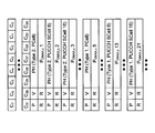
- FIG. 13 is a diagram showing an example of CA. As shown in FIG. In 13 CA, for example, it is assumed that a maximum of 32 CCs are bundled. Since it is inefficient from the viewpoint of communication overhead and controllability to transmit uplink control information (UCI) related to many CCs using only the PUCCH of the PCell, Rel. 13 CA is considering supporting PUCCH cell groups (PUCCH CG).
- PUCCH CG PUCCH cell groups
- the PUCCH cell (PUCCH setting cell) may be a PCell, or may be a SCell (PUCCH SCell) configured to be able to transmit PUCCH.
- the PUCCH cell (PUCCH setting cell) may be a PCell, or may be a SCell (PUCCH SCell) configured to be able to transmit PUCCH.
- PUCCH SCell PUCCH SCells
- FIG. 1 four PUCCH CGs each consisting of eight cells are set, and SCell 8 and SCell 24 are set as PUCCH SCells.
- PUCCH CGs are not necessarily set.
- Rel. 13 CA has been studied to support a mode in which multiple PUCCH cells are set (Multiple PUCCH CGs) and a mode in which PUCCH is transmitted only by a single cell (PCell) (Single PUCCH CG).
- FIG. 2 is a diagram illustrating an example of the PUCCH CG mode.
- FIG. 2A illustrates an example in which a user terminal transmits an uplink signal to an eNB using a plurality of cells.
- 2B and 2C show an example of the PUCCH CG mode corresponding to the example of FIG. 2A.
- a plurality of PUCCH CGs may be set (FIG. 2B), or a single PUCCH CG may be set (FIG. 2C).
- a user terminal feeds back a PHR (Power Headroom Report) including information on PH (PH information) for each serving cell to a radio base station.
- the PHR is composed of PHR MAC CE (Control Element) included in MAC PDU (Medium Access Control Protocol Data Unit).
- the PHR is transmitted by MAC signaling using PUSCH (Physical Uplink Shared Channel).
- the radio base station can dynamically control the transmission power of the user terminal based on the received PHR.
- Type 1 PH is a PH when only PUSCH is considered
- Type 2 PH is a PH when both PUSCH and PUCCH are considered.
- the PH information may be a PH value or an index associated with the PH value (or level).
- the radio base station transmits PHR setting information related to PHR transmission conditions to the user terminal. For example, RRC signaling is used for the notification.
- the user terminal determines the timing for transmitting the PHR based on the notified PHR setting information. That is, when the PHR transmission condition is satisfied, the PHR is triggered.
- the PHR setting information for example, two timers (periodicPHR-Timer and prohibitPHR-Timer) and a predetermined threshold (dl-PathlossChange) can be used.
- a predetermined threshold dl-PathlossChange
- the PHR setting information may be referred to as a PHR timer and a parameter set.
- the CC capable of transmitting the PUCCH is 1 CC or less, so the PHR configuration when the PUCCH can be transmitted at 2 CC or more is not defined. For this reason, there is a possibility that the radio base station cannot appropriately grasp the PH for a predetermined PUCCH cell.
- the present inventors have established LTE Rel.
- the present invention has been conceived to introduce a new PHR configuration different from the existing system. It came.
- FIG. 3 is a diagram showing an application range of the PHR timer and the parameter set in the first embodiment.
- all PUCCH CGs that is, all CCs
- PHR including PH information of all activated (active) CCs is transmitted.
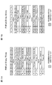
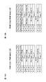
- FIG. 4 is a diagram illustrating an example of the PHR MAC CE according to the first embodiment.
- PH information for a maximum of 32 cells can be included.
- PUCCH cells PCell and PUCCH SCell
- Type 2 PH information is also included.
- the PHR is configured to include Type 2 PH information and Type 1 PH information in ascending order for each cell.
- Type 1 PH information is included for CCs that do not require notification of Type 2 PH information (SCells in which PUCCH is not set).
- PHR including PH information of all CCs can be notified to the radio base station.
- FIG. 5 is a diagram showing the applicable range of the PHR timer and parameters in the second embodiment. As shown in FIG. 5, according to the second embodiment, each PUCCH CG is managed by a separate timer and parameter set. Further, when the PHR is triggered in any CC, the PHR including the PH information of all activated (active) CCs is transmitted.
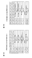
- FIG. 6 is a diagram illustrating an example of the PHR MAC CE according to the second embodiment.
- PH information for a maximum of 32 cells can be included.
- Type 2 PH information is also included.
- PHR is configured to include Type 2 PH information for the PUCCH cells in ascending order, and then include Type 1 PH information for each cell in ascending order.
- Type 1 PH information is included for CCs that do not require notification of Type 2 PH information (SCells in which PUCCH is not set).
- the examples shown in the first and second embodiments are merely examples, and the arrangement order and number of data are not limited thereto.
- the number of cells including information is not limited to a maximum of 32 cells.
- an LCID (Logical Channel ID) that is not used in the existing system (Rel. 10 to 12) may be used in correspondence with the PHR MAC CE in the first and second embodiments. That is, the MAC PDU may include a predetermined LCID in the MAC header to indicate that the MAC PDU includes the MAC CE corresponding to the PHR in the first or second embodiment.
- PHR in PHR CG unit PHR generated in units of PHR CG (PHR cell group) obtained by grouping CCs based on a predetermined rule is used.
- the PHR corresponding to the extended CA can be used based on the PHR of the existing system, there is an advantage that the mounting cost is low and the migration can be easily performed.
- FIG. 7 is a diagram illustrating an example of the timing of the PHR trigger in the first embodiment.
- the configuration of the extended CA is the same as that in FIG.
- a relatively fine TPC Transmit Power Control
- dl-PathlossChange 1 dB
- the path loss changes by 3 dB.
- the power control of PUCCH CG2 cannot be appropriately performed with the parameter set for PUCCH CG3.
- the parameter set for PUCCH CG2 there is a problem that PHR trigger by PUCCH CG3 increases and unnecessary communication increases.
- the overhead will be described as an example in which a parameter set for PUCCH CG2 is used.
- PHR by a change in the pathloss CG2 is triggered at time t 3
- PHR is triggered by a change in the pathloss CG3.
- FIG. 8 is a diagram illustrating an example of PHR transmitted at times t 1 and t 2 in FIG.
- the only CG whose PSD (transmission power density) has changed between these times is PUCCH CG2. Therefore, PH information other than PUCCH CG2 is redundant because the same (or almost the same) content is notified in these PHRs.
- FIG. 9 is a diagram illustrating an example of a relationship between surplus power (PH) and PUCCH / PUSCH transmission power.
- 9A and 9B relate to PCell.
- Each power is as follows.
- (Power used for PUSCH) P CMAX, c 2 -PH1
- (Power used for PUCCH) P CMAX, c 1 -PH2- (P CMAX, c 2 -PH1 ).
- PH1 is Type 1 PH
- PH2 is Type 2 PH.
- FIG. 9C relates to a PUCCH SCell.
- the power used for PUSCH can be obtained by P CMAX, c m-PH1.
- the radio base station cannot specify the power used for the PUCCH of the PUCCH SCell. For this reason, it is not preferable to reduce information about Type 2 PH in order to reduce overhead.
- FIG. 10 is a diagram illustrating an example of the timing of the PHR trigger in the second embodiment.
- FIG. 10A shows the PHR timer and parameter set of each PUCCH CG.
- a PHR timer and a parameter set are independently set in each CG.
- FIG. 10B is a diagram showing an example of the timing of the PHR trigger controlled according to the PHR timer and parameter set of FIG. 10A.
- the timers of both CGs are started at time 0 ms.
- CG1's prohibitPHR-Timer expires and the path loss value fluctuates by dl-PathlossChange or more, so the CG1's PHR is transmitted.
- the CG2 PHR-Timer expires and the path loss value fluctuates by dl-PathlossChange or more, so the CG2 PHR is transmitted.
- the timer of the CG is restarted.
- FIG. 11 is a diagram illustrating an example of the PHR transmitted in FIG. 10B.
- the only CG whose PSD has changed is PUCCH CG1. Therefore, PH information other than PUCCH CG1 has not changed.
- the only CG whose PSD has changed is PUCCH CG2. Therefore, PH information other than PUCCH CG2 has not changed.
- the PHR timer and the parameter set are set for each CG, the PHR includes PH information related to other CGs, resulting in unnecessary overhead.
- the present inventors examined the problems as described above. As a result, the idea was to group CCs based on a predetermined rule. In addition, the idea is to include only PH information of CCs belonging to a predetermined group instead of including PH information of all active CCs in the PHR.
- the inventors have found a third embodiment of the present invention based on these ideas. According to the configuration of the third embodiment of the present invention, the PHR timer and parameters can be set independently for each group, and the PHR overhead can be greatly reduced.
- a PHR cell group (PHR CG) is set in the user terminal.
- the PHR CG is configured to include one or more CCs.
- the user terminal controls PHR transmission timing using different PHR timers and parameters.
- the PHR CG may be configured based on an existing CG or a separately specified CG.
- the PHR CG may be configured based on PUCCH CG, or may be configured based on TAG (Timing Advance Group).
- the user terminal is configured to include only information related to the PH of the active cell belonging to a specific PHR CG in a predetermined MAC CE. Moreover, regarding PUCCH cells (PCell and PUCCH SCell), not only Type 1 PH information but also Type 2 PH information is included.
- PUCCH CG is given as an example of another type of CG, but is not limited to this.
- a user terminal shall be set to carry out 32CC CA, it is not restricted to this.
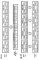
- FIG. 12 is a diagram illustrating an example of a correspondence relationship between PHR CG and PUCCH CG.
- FIG. 12A shows an example when the user terminal is configured with a single PUCCH CG. In this example, CCs included in the PUCCH CG are allocated to four PHR CGs with 8 CC as a structural unit.
- FIG. 12B shows an example when the user terminal is set with a plurality of PUCCH CGs. In this example, one PUCCH CG is configured to correspond to one PHR CG.
- FIG. 13 is a diagram showing another example of the correspondence between PHR CG and PUCCH CG.
- FIG. 13A shows an example of a configuration in which the number of PHR CGs is greater than the number of PUCCH CGs. In this example, a plurality of PHR CGs are configured to correspond to one PUCCH CG.
- FIG. 13B illustrates an example of a configuration in which the number of PHR CGs is smaller than the number of PUCCH CGs. In this example, one PHR CG is configured to correspond to a plurality of PUCCH CGs.
- the PHR CG can be configured flexibly. Therefore, an appropriate PHR CG can be set according to the combination of CCs to which the same PHR timer and parameters are to be applied.
- the information regarding the configuration of the PHR CG may be notified to the user terminal by, for example, a downlink control signal (DCI), higher layer signaling (for example, RRC signaling), broadcast information, or a combination thereof.
- DCI downlink control signal
- RRC signaling higher layer signaling
- the setting information of the correspondence relationship between the PHR CG and the PUCCH CGC may be notified, or the information of the CC configuring the PHR CG may be notified.
- Information regarding the configuration of the PHR CG may be transmitted together with the PHR setting information or included in the PHR setting information.
- the information regarding the structure of PHR CG may be preset.
- PHR transmission method In the third embodiment, the following two methods will be described as PHR transmission methods.
- the PHR CGn (n is a natural number, for example) PHR is transmitted in one of the activated CCs included in the PHR CGn.
- PHR CGn (n is a natural number, for example) PHR is transmitted in any activated cell regardless of PHR CG.
- the PHR MAC CE related to a predetermined CG can be transmitted in a cell belonging to the predetermined CG. Further, in the method 2, the PHR MAC CE related to a predetermined CG can be transmitted by a CC belonging to the same CG as the predetermined CG and / or a CC belonging to a different CG.
- These PHR MAC CEs can contain more information than conventional PHR MAC CEs (Extended PHR MAC CE, Dual Connectivity PHR MAC CE, etc.).
- FIG. 14 is a conceptual explanatory diagram of Method 1.
- the user terminal is set to perform CA at 32 CC
- PHR CG1 is configured with PCell and SCell 1-15
- PHR CG2 is configured with SCell 16-31.
- PUSCHs are assigned to SCell 15 and SCell 16, and PHR CG1 and PHR 2 are transmitted on these PUSCHs, respectively.
- the PHR CGs 1 and 2 correspond to the PUCCH CGs 1 and 2, respectively, but are not limited to this configuration.
- FIG. 15 is a diagram showing an example of the configuration of the PHR MAC CE transmitted in FIG. In FIG. 14, each PHR CG is composed of 16 CCs. For this reason, as shown in FIG. 15A, the PHR MAC CE of PHR CG1 is configured to include 16 CC PH information included in PHR CG1. Further, as shown in FIG. 15B, the PHR MAC CE of PHR CG2 is configured to include 16 CC PH information included in PHR CG2.
- PHR is transmitted using each CG at 70 ms and 90 ms, since these PHRs include only the PH information of CCs belonging to the respective CGs, redundant information is not transmitted.
- the PHR of Method 1 includes information for indicating that it is a new PHR different from the existing PHR.
- the new PHR may be referred to as PHR CG PHR.
- the MAC PDU in Method 1 includes an LCID that is not used in the existing system (Rel. 10 to 12) in the MAC header.
- FIG. 16 is a diagram illustrating an example of the LCID value used for the uplink shared channel.
- the LCID corresponding to the index “10111” indicates that the MAC PDU including the LCID includes a MAC CE corresponding to the PHR CG PHR.
- the LCID corresponding to the index “10111” is only reserved and has not been used.
- the LCID indicating the PHR CG PHR is not limited to the configuration in FIG. 16, and may be assigned to another index, for example.
- Method 1 when a radio base station that has received PHR detects an LCID indicating PHR CG PHR, it determines that the PHR includes PH information of the CG used for PHR transmission. That is, the radio base station grasps the CG corresponding to the PHR according to the PHR CG to which the UL serving cell used for PHR transmission belongs.
- the PHR MAC CE does not include the PH information of all active CCs, but includes only the PH information of CCs belonging to the PHR CG that transmits the PHR, thereby suitably reducing overhead. be able to.
- the PHR of the PHR CG may not be transmitted regardless of a timer or the like. By doing so, it is possible to suppress the opportunity for unnecessary transmission (inactive) CC PHRs to be transmitted unnecessarily, and to further reduce the overhead.
- Method 2 can be broadly divided into two.
- One is a method (method 2-1) including a MAC CE in which a plurality of CG-related PHs can be included in a MAC PDU.
- the other is a method (method 2-2) in which a MAC PDU includes a plurality of MAC CEs that can include a PH related to one CG.
- FIG. 17 is a conceptual explanatory diagram of Method 2.
- the user terminal is set to perform CA at 32 CCs, and PHR CG1 is configured to include PCell and SCell 1 to 15 and PHR CG2 is configured to include SCell 16 to 31.
- the PUSCH is assigned only to the SCell 15 and the PHRs CG1 and PHR 2 are transmitted on the PUSCH.
- the PHR CGs 1 and 2 correspond to the PUCCH CGs 1 and 2, respectively, but are not limited to this configuration.
- the PHR MAC CE of the method 2-1 includes a field for specifying which PHR CG the PHR MAC CE includes information corresponding to.
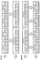
- FIG. 18 is a diagram illustrating an example of the configuration of the PHR MAC CE transmitted in FIG.
- CG i a field “CG i ” that does not exist in the existing PHR MAC CE is added.
- the field “CG i ” is used to indicate whether the MAC CE includes information on a predetermined PHR CG (PHR CGi). For example, when CG i is “1”, it may indicate that PH information of PHR CGi is included, and when CG i is “0”, it may indicate that PH information of PHR CGi is not included.
- FIG. 18A shows an example of information included in the PHR CG1 PHR MAC CE.
- the radio base station that receives the MAC CE can recognize that the MAC CE includes information on CG1.
- FIG. 18B shows an example of information included in the PHR CG2 PHR MAC CE.
- the radio base station that receives the MAC CE recognizes that the MAC CE includes information on CG2.
- the number of CG i contained in the MAC CE (i.e., the maximum number of PHR CG is set) is not limited thereto .
- the maximum number of PHR CGs may be 4, 8, 16, 32, etc.
- the PHR of the method 2-1 includes information for indicating that it is a new PHR different from the existing PHR.
- the MAC PDU of Method 2-1 includes an LCID that is not used in the existing system (Rel. 10 to 12) in the MAC header.
- the LCID may be the same as or different from the new LCID described above for Method 1.
- the radio base station that has received the PHR detects, for example, an LCID indicating the PHR CG PHR
- the radio base station determines that the PHR includes PH information of a plurality of CGs. Then, based on the CG i field of the MAC CE, the radio base station recognizes which CG the PH information about which the MAC CE includes, and acquires the PH information about the recognized CG.
- method 2-2 will be described.
- the same PHR MAC CE as the method 1 (MAC CE not including a field for specifying which PHR CG includes information corresponding to the PHR CG) can be used.
- a different LCID is set for each PHR CG in order to distinguish PHR MAC CEs related to multiple PHR CGs.
- FIG. 19 is a diagram illustrating another example of the method 2.
- FIG. 19A is a diagram illustrating another example of the LCID value used for the uplink shared channel.
- the LCID corresponding to the index “10111” indicates that the MAC PDU includes the PHR MAC CE for PHR CG1 (for example, PHR CG1 PHR MAC CE in FIG. 15A).
- the LCID corresponding to the index “10110” indicates that the MAC PDU includes the PHR MAC CE for PHR CG2 (eg, PHR CG2 PHR MAC CE in FIG. 15B).
- the LCIDs corresponding to the indexes “10111” and “10110” are only reserved and have not been used.
- the LCID indicating PHR CG PHR is not limited to the configuration in FIG. 19A, and may be assigned to another index, for example. Further, not only in the method 2-2 but also in the method 1, a different LCID may be set for each PHR CG as shown in FIG. 19A.
- FIG. 19B is a diagram illustrating an example of a MAC PDU including a PHR MAC CE in the method 2-2.
- Method 2-2 when the radio base station that has received the PHR detects an LCID indicating a predetermined PHR CG PHR, the radio base station determines that the PHR includes PH information of the corresponding CG. Then, the radio base station acquires PH information related to the corresponding CG based on the recognized MAC CE.
- method 2 it is sufficient to include PH information of CCs belonging to a predetermined PHR CG instead of including PH information of all active CCs in PHR. Can do. Moreover, since the user terminal can transmit PHR of arbitrary CG using arbitrary CC, it can perform the traffic control between CC more flexibly.
- Method 2-1 it is possible to include PH information regarding a plurality of CGs by providing a new field indicating CG in the MAC CE.
- a plurality of PHR MAC CEs corresponding to different CGs can be included in the MAC PDU by defining a plurality of LCIDs.
- the PHR of the PHR CG may not be transmitted regardless of a timer or the like. By doing so, it is possible to suppress the opportunity for unnecessary transmission (inactive) CC PHRs to be transmitted unnecessarily, and to further reduce the overhead.
- wireless communication system Wireless communication system
- the wireless communication method according to each embodiment of the present invention is applied.
- wireless communication method which concerns on each said embodiment may be applied independently, respectively, and may be applied in combination.
- FIG. 20 is a diagram illustrating an example of a schematic configuration of a wireless communication system according to an embodiment of the present invention.
- carrier aggregation (CA) and / or dual connectivity (DC) in which a plurality of basic frequency blocks (component carriers) each having a system bandwidth (for example, 20 MHz) of the LTE system as one unit are applied.
- the wireless communication system 1 may be referred to as SUPER 3G, LTE-A (LTE-Advanced), IMT-Advanced, 4G, 5G, FRA (Future Radio Access), or the like.
- the radio communication system 1 shown in FIG. 20 includes a radio base station 11 that forms a macro cell C1, and radio base stations 12a-12c that are arranged in the macro cell C1 and form a small cell C2 that is narrower than the macro cell C1. . Moreover, the user terminal 20 is arrange
- the user terminal 20 can be connected to both the radio base station 11 and the radio base station 12. It is assumed that the user terminal 20 uses the macro cell C1 and the small cell C2 that use different frequencies simultaneously by CA or DC. In addition, the user terminal 20 can apply CA or DC using a plurality of cells (CC) (for example, six or more CCs).
- CC cells
- Communication between the user terminal 20 and the radio base station 11 can be performed using a carrier having a relatively low frequency band (for example, 2 GHz) and a narrow bandwidth (referred to as an existing carrier or a legacy carrier).
- a carrier having a relatively high frequency band for example, 3.5 GHz, 5 GHz, etc.
- the same carrier may be used.
- the configuration of the frequency band used by each radio base station is not limited to this.
- a wired connection for example, an optical fiber compliant with CPRI (Common Public Radio Interface), an X2 interface, etc.
- a wireless connection It can be set as the structure to do.
- the radio base station 11 and each radio base station 12 are connected to the higher station apparatus 30 and connected to the core network 40 via the higher station apparatus 30.
- the upper station device 30 includes, for example, an access gateway device, a radio network controller (RNC), a mobility management entity (MME), and the like, but is not limited thereto.
- RNC radio network controller
- MME mobility management entity
- Each radio base station 12 may be connected to the higher station apparatus 30 via the radio base station 11.
- the radio base station 11 is a radio base station having a relatively wide coverage, and may be called a macro base station, an aggregation node, an eNB (eNodeB), a transmission / reception point, or the like.
- the radio base station 12 is a radio base station having local coverage, and includes a small base station, a micro base station, a pico base station, a femto base station, a HeNB (Home eNodeB), an RRH (Remote Radio Head), and transmission / reception. It may be called a point.
- the radio base stations 11 and 12 are not distinguished, they are collectively referred to as a radio base station 10.
- Each user terminal 20 is a terminal compatible with various communication methods such as LTE and LTE-A, and may include not only a mobile communication terminal but also a fixed communication terminal.
- OFDMA orthogonal frequency division multiple access
- SC-FDMA single carrier-frequency division multiple access
- OFDMA is a multi-carrier transmission scheme that performs communication by dividing a frequency band into a plurality of narrow frequency bands (subcarriers) and mapping data to each subcarrier.
- SC-FDMA is a single-carrier transmission scheme that reduces interference between terminals by dividing the system bandwidth into bands consisting of one or continuous resource blocks for each terminal and using a plurality of terminals with mutually different bands. is there.
- the uplink and downlink radio access methods are not limited to these combinations.
- downlink channels include a downlink shared channel (PDSCH) shared by each user terminal 20, a broadcast channel (PBCH: Physical Broadcast Channel), a downlink L1 / L2 control channel, and the like. Used. User data, higher layer control information, SIB (System Information Block), etc. are transmitted by PDSCH. Also, MIB (Master Information Block) is transmitted by PBCH.
- PDSCH downlink shared channel
- PBCH Physical Broadcast Channel
- SIB System Information Block
- MIB Master Information Block
- Downlink L1 / L2 control channels include PDCCH (Physical Downlink Control Channel), EPDCCH (Enhanced Physical Downlink Control Channel), PCFICH (Physical Control Format Indicator Channel), PHICH (Physical Hybrid-ARQ Indicator Channel), and the like.
- Downlink control information (DCI: Downlink Control Information) including scheduling information of PDSCH and PUSCH is transmitted by PDCCH.
- the number of OFDM symbols used for PDCCH is transmitted by PCFICH.
- the HAICH transmission confirmation signal (ACK / NACK) for PUSCH is transmitted by PHICH.
- EPDCCH is frequency-division multiplexed with PDSCH (downlink shared data channel), and is used for transmission of DCI and the like in the same manner as PDCCH.
- an uplink shared channel (PUSCH: Physical Uplink Shared Channel), an uplink control channel (PUCCH: Physical Uplink Control Channel), and a random access channel (PRACH) shared by each user terminal 20 are used. Physical Random Access Channel) is used.
- PUSCH Physical Uplink Shared Channel
- PUCCH Physical Uplink Control Channel
- PRACH random access channel
- Physical Random Access Channel Physical Random Access Channel
- User data and higher layer control information are transmitted by PUSCH.
- downlink radio quality information (CQI: Channel Quality Indicator), a delivery confirmation signal, and the like are transmitted by PUCCH.
- a random access preamble for establishing connection with a cell is transmitted by the PRACH.
- FIG. 21 is a diagram illustrating an example of the overall configuration of a radio base station according to an embodiment of the present invention.
- the radio base station 10 includes a plurality of transmission / reception antennas 101, an amplifier unit 102, a transmission / reception unit 103, a baseband signal processing unit 104, a call processing unit 105, and a transmission path interface 106.
- the transmission / reception antenna 101, the amplifier unit 102, and the transmission / reception unit 103 may each be configured to include one or more.
- User data transmitted from the radio base station 10 to the user terminal 20 via the downlink is input from the higher station apparatus 30 to the baseband signal processing unit 104 via the transmission path interface 106.
- PDCP Packet Data Convergence Protocol
- RLC Radio Link Control
- MAC Medium Access Control
- HARQ Hybrid Automatic Repeat reQuest
- the downlink control signal is also subjected to transmission processing such as channel coding and inverse fast Fourier transform, and is transferred to the transmission / reception unit 103.
- the transmission / reception unit 103 converts the baseband signal output by precoding for each antenna from the baseband signal processing unit 104 to a radio frequency band and transmits the converted signal.
- the radio frequency signal frequency-converted by the transmission / reception unit 103 is amplified by the amplifier unit 102 and transmitted from the transmission / reception antenna 101.
- the transmission / reception unit 103 can be configured by a transmitter / receiver, a transmission / reception circuit, or a transmission / reception device which is described based on common recognition in the technical field according to the present invention.
- the transmission / reception part 103 may be comprised as an integral transmission / reception part, and may be comprised from a transmission part and a receiving part.
- the radio frequency signal received by the transmission / reception antenna 101 is amplified by the amplifier unit 102.
- the transmission / reception unit 103 receives the uplink signal amplified by the amplifier unit 102.
- the transmission / reception unit 103 converts the frequency of the received signal into a baseband signal and outputs it to the baseband signal processing unit 104.
- the baseband signal processing unit 104 performs fast Fourier transform (FFT) processing, inverse discrete Fourier transform (IDFT: Inverse Discrete Fourier Transform) processing, and error correction on user data included in the input upstream signal.
- FFT fast Fourier transform
- IDFT inverse discrete Fourier transform
- Decoding, MAC retransmission control reception processing, RLC layer and PDCP layer reception processing are performed and transferred to the upper station apparatus 30 via the transmission path interface 106.
- the call processing unit 105 performs call processing such as communication channel setting and release, state management of the radio base station 10, and radio resource management.
- the transmission / reception unit 103 transmits, to the user terminal 20, a downlink signal including uplink transmission power control information generated by a transmission signal generation unit 302 described later, PHR setting information, and the like.
- the transmission path interface 106 transmits and receives signals to and from the higher station apparatus 30 via a predetermined interface.
- the transmission path interface 106 transmits and receives (backhaul signaling) signals to and from the adjacent radio base station 10 via an interface between base stations (for example, an optical fiber compliant with CPRI (Common Public Radio Interface), X2 interface). Also good.
- CPRI Common Public Radio Interface
- X2 interface also good.
- FIG. 22 is a diagram illustrating an example of a functional configuration of the radio base station according to the present embodiment. Note that FIG. 22 mainly shows functional blocks of characteristic portions in the present embodiment, and the wireless base station 10 also has other functional blocks necessary for wireless communication. As illustrated in FIG. 22, the baseband signal processing unit 104 includes a control unit (scheduler) 301, a transmission signal generation unit 302, a mapping unit 303, a reception signal processing unit 304, and a measurement unit 305. Yes.
- the baseband signal processing unit 104 includes a control unit (scheduler) 301, a transmission signal generation unit 302, a mapping unit 303, a reception signal processing unit 304, and a measurement unit 305.
- the control unit (scheduler) 301 controls the entire radio base station 10.
- the control part 301 can be comprised from the controller, the control circuit, or control apparatus demonstrated based on the common recognition in the technical field which concerns on this invention.
- the control unit 301 controls signal generation by the transmission signal generation unit 302 and signal allocation by the mapping unit 303, for example.
- the control unit 301 also controls signal reception processing by the reception signal processing unit 304 and signal measurement by the measurement unit 305.
- the control unit 301 controls scheduling (for example, resource allocation) of system information, a downlink data signal transmitted on the PDSCH, and a downlink control signal transmitted on the PDCCH and / or EPDCCH. It also controls scheduling of synchronization signals and downlink reference signals such as CRS (Cell-specific Reference Signal), CSI-RS (Channel State Information Reference Signal), DM-RS (Demodulation Reference Signal).
- CRS Cell-specific Reference Signal
- CSI-RS Channel State Information Reference Signal
- DM-RS Demodulation Reference Signal
- the control unit 301 also transmits an uplink data signal transmitted on the PUSCH, an uplink control signal transmitted on the PUCCH and / or PUSCH (for example, a delivery confirmation signal (HARQ-ACK)), a random access preamble transmitted on the PRACH, Controls scheduling of uplink reference signals and the like.
- an uplink data signal transmitted on the PUSCH for example, an uplink control signal transmitted on the PUCCH and / or PUSCH (for example, a delivery confirmation signal (HARQ-ACK)), a random access preamble transmitted on the PRACH, Controls scheduling of uplink reference signals and the like.
- HARQ-ACK delivery confirmation signal
- control unit 301 controls the transmission signal generation unit 302 and the mapping unit 303 in order to adjust the uplink transmission power of the user terminal 20 connected to the radio base station 10.
- control unit 301 includes a transmission power control (TPC) command based on PHR and channel state information (CSI) reported from the user terminal 20, an uplink data error rate, the number of HARQ retransmissions, and the like.
- TPC transmission power control
- CSI channel state information
- An instruction is given to the transmission signal generation unit 302 to generate downlink control information (DCI), and the mapping unit 303 is controlled to notify the user terminal 20 of the DCI.
- DCI downlink control information
- the control unit 301 acquires the PH related to each active CC used by the user terminal 20 based on the PHR input from the received signal processing unit 304.
- the PHR is a PHR (first embodiment) obtained by further extending the PHR used in the conventional CA, a PHR (second embodiment) obtained by further extending the PHR used in the conventional DC, and a PHR CG unit.
- PHR (third embodiment) or the like that can change whether or not PH information is included is used.
- control unit 301 calculates (estimates) surplus transmission power for each CC based on the PHR notified from the user terminal 20. Then, scheduling and transmission power control may be performed in consideration of surplus transmission power.
- control unit 301 may control the transmission signal generation unit 302 and the mapping unit 303 so as to generate information for setting the PHR timer and the parameter set (PHR setting information) and transmit the information to the user terminal 20.
- the information includes, for example, information indicating that one timer and parameter set is applied to all CGs (all CCs) (first embodiment), information indicating that different timers and parameter sets are applied to each CG (first 2, the third embodiment).
- the transmission signal generation unit 302 generates a downlink signal (downlink control signal, downlink data signal, downlink reference signal, etc.) based on an instruction from the control unit 301, and outputs it to the mapping unit 303.
- the transmission signal generation unit 302 can be configured by a signal generator, a signal generation circuit, or a signal generation device described based on common recognition in the technical field according to the present invention.
- the transmission signal generation unit 302 generates, for example, a DL assignment that notifies downlink signal allocation information and a UL grant that notifies uplink signal allocation information based on an instruction from the control unit 301.
- the downlink data signal is subjected to coding processing and modulation processing according to a coding rate, a modulation scheme, and the like determined based on channel state information (CSI: Channel State Information) from each user terminal 20.
- CSI Channel State Information
- the transmission signal generation unit 302 generates a downlink signal including information for controlling the uplink transmission power of the user terminal 20, PHR setting information, and the like.
- the mapping unit 303 maps the downlink signal generated by the transmission signal generation unit 302 to a predetermined radio resource based on an instruction from the control unit 301, and outputs it to the transmission / reception unit 103.
- the mapping unit 303 can be configured by a mapper, a mapping circuit, or a mapping device described based on common recognition in the technical field according to the present invention.
- the reception signal processing unit 304 performs reception processing (for example, demapping, demodulation, decoding, etc.) on the reception signal input from the transmission / reception unit 103.
- the received signal is, for example, an uplink signal (uplink control signal, uplink data signal, uplink reference signal, etc.) transmitted from the user terminal 20.
- the reception signal processing unit 304 can be configured by a signal processor, a signal processing circuit, or a signal processing device described based on common recognition in the technical field according to the present invention.
- the reception signal processing unit 304 outputs the information decoded by the reception processing to the control unit 301.
- the reception signal processing unit 304 outputs the reception signal and the signal after reception processing to the measurement unit 305.
- the measurement unit 305 performs measurement on the received signal.
- the measurement part 305 can be comprised from the measuring device, measurement circuit, or measurement apparatus demonstrated based on common recognition in the technical field which concerns on this invention.
- the measurement unit 305 may measure, for example, received power (for example, RSRP (Reference Signal Received Power)), reception quality (for example, RSRQ (Reference Signal Received Quality)), channel state, and the like of the received signal.
- the measurement result may be output to the control unit 301.
- FIG. 23 is a diagram illustrating an example of the overall configuration of the user terminal according to the present embodiment.
- the user terminal 20 includes a plurality of transmission / reception antennas 201, an amplifier unit 202, a transmission / reception unit 203, a baseband signal processing unit 204, and an application unit 205.
- the transmission / reception antenna 201, the amplifier unit 202, and the transmission / reception unit 203 may each be configured to include one or more.
- the radio frequency signal received by the transmission / reception antenna 201 is amplified by the amplifier unit 202.
- the transmission / reception unit 203 receives the downlink signal amplified by the amplifier unit 202.
- the transmission / reception unit 203 converts the frequency of the received signal into a baseband signal and outputs it to the baseband signal processing unit 204.
- the transmission / reception unit 203 can be configured by a transmitter / receiver, a transmission / reception circuit, or a transmission / reception device described based on common recognition in the technical field according to the present invention.
- the transmission / reception unit 203 may be configured as an integral transmission / reception unit, or may be configured from a transmission unit and a reception unit.
- the transmission / reception unit 203 receives information for controlling the uplink transmission power of the user terminal 20, a downlink signal including PHR setting information, and the like. Moreover, you may receive the information regarding the structure of PHR CG (3rd Embodiment).
- the baseband signal processing unit 204 performs FFT processing, error correction decoding, retransmission control reception processing, and the like on the input baseband signal.
- the downlink user data is transferred to the application unit 205.
- the application unit 205 performs processing related to layers higher than the physical layer and the MAC layer.
- broadcast information in the downlink data is also transferred to the application unit 205.
- uplink user data is input from the application unit 205 to the baseband signal processing unit 204.
- the baseband signal processing unit 204 performs transmission / reception by performing retransmission control transmission processing (for example, HARQ transmission processing), channel coding, precoding, discrete Fourier transform (DFT) processing, IFFT processing, and the like. Is transferred to the unit 203.
- the transmission / reception unit 203 converts the baseband signal output from the baseband signal processing unit 204 into a radio frequency band and transmits it.
- the radio frequency signal frequency-converted by the transmission / reception unit 203 is amplified by the amplifier unit 202 and transmitted from the transmission / reception antenna 201.
- FIG. 24 is a diagram illustrating an example of a functional configuration of the user terminal according to the present embodiment. Note that FIG. 24 mainly shows functional blocks of characteristic portions in the present embodiment, and the user terminal 20 also has other functional blocks necessary for wireless communication. As illustrated in FIG. 24, the baseband signal processing unit 204 included in the user terminal 20 includes a control unit 401, a transmission signal generation unit 402, a mapping unit 403, a reception signal processing unit 404, and a measurement unit 405. I have.
- the control unit 401 controls the entire user terminal 20.
- the control unit 401 can be composed of a controller, a control circuit, or a control device described based on common recognition in the technical field according to the present invention.
- the control unit 401 controls, for example, signal generation by the transmission signal generation unit 402 and signal allocation by the mapping unit 403.
- the control unit 401 controls signal reception processing by the reception signal processing unit 404 and signal measurement by the measurement unit 405.
- the control unit 401 obtains, from the received signal processing unit 404, a downlink control signal (a signal transmitted by PDCCH / EPDCCH) and a downlink data signal (a signal transmitted by PDSCH) transmitted from the radio base station 10.
- the control unit 401 generates an uplink control signal (for example, an acknowledgment signal (HARQ-ACK)) or an uplink data signal based on a downlink control signal, a result of determining whether retransmission control is necessary for the downlink data signal, or the like.
- HARQ-ACK acknowledgment signal
- control unit 401 controls the uplink transmission power of the user terminal 20. Specifically, the control unit 401 controls the transmission power of each CC based on signaling (for example, a TPC command) from the radio base station 20. Moreover, the control part 401 calculates PH of each CC based on the maximum permissible transmission power for every CC, PUCCH transmission power, PUSCH transmission power, etc. The calculated PH is output to the transmission signal generation unit 402 and used to create a PHR.
- signaling for example, a TPC command
- the control unit 401 sets the PHR timer and the parameter for the measurement unit 405. . Furthermore, the control unit 401 responds to the transmission signal generation unit 402 and the mapping unit 403 when notified from the measurement unit 405 to trigger PHR related to a predetermined CG (for example, PUCCH CG, PHR CG). Control to generate and transmit PHR.
- a predetermined CG for example, PUCCH CG, PHR CG
- the transmission signal generation unit 402 generates an uplink signal (uplink control signal, uplink data signal, uplink reference signal, etc.) based on an instruction from the control unit 401 and outputs the uplink signal to the mapping unit 403.
- the transmission signal generation unit 402 can be configured by a signal generator, a signal generation circuit, or a signal generation device described based on common recognition in the technical field according to the present invention.
- the transmission signal generation unit 402 generates an uplink control signal related to a delivery confirmation signal (HARQ-ACK) or channel state information (CSI) based on an instruction from the control unit 401, for example.
- the transmission signal generation unit 402 generates an uplink data signal based on an instruction from the control unit 401.
- the transmission signal generation unit 402 is instructed by the control unit 401 to generate an uplink data signal when the UL grant is included in the downlink control signal notified from the radio base station 10.
- the transmission signal generation unit 402 Based on an instruction from the control unit 401, the transmission signal generation unit 402 generates a PHR MAC CE including PH information regarding one CG or a plurality of CGs, forms a MAC PDU, and outputs the MAC PDU to the mapping unit 403 To do.
- the transmission signal generation unit 402 may include information (for example, LCID) for specifying the CG related to the PHR MAC CE in the MAC PDU. Note that the transmission signal generation unit 402 determines which one of the PHR of each embodiment and the PHR of the existing system to use according to the number of CCs set in the user terminal 20, and transmits a transmission signal including the determined PHR. You may make it produce
- the mapping unit 403 maps the uplink signal generated by the transmission signal generation unit 402 to a radio resource based on an instruction from the control unit 401, and outputs the radio signal to the transmission / reception unit 203.
- the mapping unit 403 can be configured by a mapper, a mapping circuit, or a mapping device described based on common recognition in the technical field according to the present invention.
- the reception signal processing unit 404 performs reception processing (for example, demapping, demodulation, decoding, etc.) on the reception signal input from the transmission / reception unit 203.
- the received signal is, for example, a downlink signal (downlink control signal, downlink data signal, downlink reference signal, etc.) transmitted from the radio base station 10.
- the reception signal processing unit 404 can be configured by a signal processor, a signal processing circuit, or a signal processing device described based on common recognition in the technical field according to the present invention. Further, the reception signal processing unit 404 can constitute a reception unit according to the present invention.
- the reception signal processing unit 404 outputs the information decoded by the reception processing to the control unit 401.
- the reception signal processing unit 404 outputs broadcast information, system information, RRC signaling, DCI, and the like to the control unit 401, for example.
- the reception signal processing unit 404 outputs the reception signal and the signal after reception processing to the measurement unit 405.
- the measurement unit 405 performs measurement on the received signal.
- the measurement part 405 can be comprised from the measuring device, measurement circuit, or measurement apparatus demonstrated based on common recognition in the technical field which concerns on this invention.
- the measurement unit 405 may measure, for example, the received power (for example, RSRP), reception quality (for example, RSRQ), channel state, and the like of the received signal.
- the measurement result may be output to the control unit 401.
- the measurement unit 405 can measure the downlink path loss of each CC.
- the measurement unit 405 has two PHR timers (periodicPHR-Timer and prohibitPHR-Timer).
- the measurement unit 405 is set with information on the PHR timer and path loss from the control unit 401. Based on the PHR timer and path loss, the measurement unit 405 notifies the control unit 401 to trigger PHR related to a predetermined CG.
- each functional block is realized by one physically coupled device, or may be realized by two or more physically separated devices connected by wire or wirelessly and by a plurality of these devices. Good.
- the radio base station 10 and the user terminal 20 are realized using hardware such as ASIC (Application Specific Integrated Circuit), PLD (Programmable Logic Device), and FPGA (Field Programmable Gate Array). May be.
- the radio base station 10 and the user terminal 20 are each a computer device including a processor (CPU: Central Processing Unit), a communication interface for network connection, a memory, and a computer-readable storage medium holding a program. It may be realized. That is, the radio base station, user terminal, and the like according to an embodiment of the present invention may function as a computer that performs processing of the radio communication method according to the present invention.
- Computer-readable recording media include, for example, flexible disks, magneto-optical disks, ROM (Read Only Memory), EPROM (Erasable Programmable ROM), CD-ROM (Compact Disc-ROM), RAM (Random Access Memory), A storage medium such as a hard disk.
- the program may be transmitted from a network via a telecommunication line.
- the radio base station 10 and the user terminal 20 may include an input device such as an input key and an output device such as a display.
- the functional configurations of the radio base station 10 and the user terminal 20 may be realized by the hardware described above, may be realized by a software module executed by a processor, or may be realized by a combination of both.
- the processor controls the entire user terminal by operating an operating system. Further, the processor reads programs, software modules and data from the storage medium into the memory, and executes various processes according to these.
- the program may be a program that causes a computer to execute the operations described in the above embodiments.
- the control unit 401 of the user terminal 20 may be realized by a control program stored in a memory and operated by a processor, and may be realized similarly for other functional blocks.
Landscapes
- Engineering & Computer Science (AREA)
- Computer Networks & Wireless Communication (AREA)
- Signal Processing (AREA)
- Mobile Radio Communication Systems (AREA)
Abstract
ユーザ端末に設定可能なコンポーネントキャリア数が既存システムより拡張される場合であっても、通信を適切に行うこと。本発明の一態様に係るユーザ端末は、複数のコンポーネントキャリア(CC:Component Carrier)を利用して通信可能なユーザ端末であって、アクティベートされたCCのうち、所定のセルグループを構成するCCごとのPH(Power Headroom)に関する情報を含むPHR(Power Headroom Report)を生成する生成部と、生成したPHRを送信する送信部と、を有する。
Description
本発明は、次世代移動通信システムにおけるユーザ端末、無線基地局及び無線通信方法に関する。
UMTS(Universal Mobile Telecommunications System)ネットワークにおいて、さらなる高速データレート、低遅延などを目的としてロングタームエボリューション(LTE:Long Term Evolution)が仕様化された(非特許文献1)。そして、LTEからのさらなる広帯域化及び高速化を目的として、LTEアドバンストと呼ばれるLTEの後継システム(LTE-Aとも呼ばれる)が検討され、LTE Rel.10~12として仕様化されている。
LTE Rel.10~12の広帯域化技術の1つは、キャリアアグリゲーション(CA:Carrier Aggregation)である。CAによれば、複数の基本周波数ブロックを一体として通信に用いることができる。CAにおける基本周波数ブロックは、コンポーネントキャリア(CC:Component Carrier)と呼ばれ、LTE Rel.8のシステム帯域に相当する。
また、LTEでは、ユーザ端末(UE)がネットワーク側の装置(例えば、無線基地局(eNB))に対して、サービングセル毎の上り余剰送信電力(PH:Power Headroom)に関する情報を含むPHR(Power Headroom Report)をフィードバックする。無線基地局は、PHRに基づいてユーザ端末の上り送信電力を動的に制御することができる。
LTEの後継システム(LTE Rel.10~12)におけるCAでは、ユーザ端末あたりの設定可能なCC数が最大5個に制限されている。一方、LTEのさらなる後継システムであるLTE Rel.13以降では、より柔軟かつ高速な無線通信を実現するために、ユーザ端末に設定可能なCC数の制限を緩和し、6個以上のCC(5個を超えるCC)を設定することが検討されている。ここで、設定可能なCC数を6個以上とするキャリアアグリゲーションは、例えば、拡張CAなどと呼ばれてもよい。
しかしながら、ユーザ端末に設定可能なCC数が6個以上(例えば、32個)に拡張される場合、既存システム(Rel.10~12)におけるPHRの利用方法をそのまま適用することが困難となる。例えば、既存システムでは、5CC以下のCAを前提としているため、6CC以上のCAを適用する場合、各CCについてのPHに関する情報を無線基地局に適切なタイミングで通知できない場合がある。このため、無線基地局がユーザ端末の上り送信電力を適切に制御できなくなるおそれがある。
本発明はかかる点に鑑みてなされたものであり、ユーザ端末に設定可能なコンポーネントキャリア数が既存システムより拡張される場合であっても、通信を適切に行うことができるユーザ端末、無線基地局及び無線通信方法を提供することを目的とする。
本発明の一態様に係るユーザ端末は、複数のコンポーネントキャリア(CC:Component Carrier)を利用して通信可能なユーザ端末であって、アクティベートされたCCのうち、所定のセルグループを構成するCCごとのPH(Power Headroom)に関する情報を含むPHR(Power Headroom Report)を生成する生成部と、生成したPHRを送信する送信部と、を有する。
本発明によれば、ユーザ端末に設定可能なコンポーネントキャリア数が既存システムより拡張される場合であっても、通信を適切に行うことができる。
従来のLTEの後継システム(LTE Rel.10~12)におけるCAでは、ユーザ端末当たりに設定可能なCC数が最大5個に制限されている。一方、LTEのさらなる後継システムであるLTE Rel.13以降においては、ユーザ端末当たりに設定可能なCCの数の制限を緩和し、6個以上のCC(セル)を設定する拡張キャリアアグリゲーション(CA enhancement、enhanced CA、Rel.13 CAなどともいう)が検討されている。
図1は、Rel.13 CAの一例を示す図である。図1に示すように、Rel.13 CAでは、例えば、最大32個のCCを束ねることが想定される。このように多くのCCに関する上り制御情報(UCI)をPCellのPUCCHのみで送信することは、通信オーバヘッドや制御性の観点から非効率であるため、Rel.13 CAではPUCCHセルグループ(PUCCH CG)をサポートすることが検討されている。
PUCCH CGごとに1つのPUCCHセルが設定される。例えば、PUCCHセル(PUCCH設定セル)は、PCellであってもよいし、PUCCH送信可能に設定されたSCell(PUCCH SCell)であってもよい。図1の場合、それぞれ8つのセルから構成されるPUCCH CGが4つ設定されており、SCell 8やSCell 24などがPUCCH SCellとして設定されている。
なお、PUCCH CGは、必ずしも2つ以上設定されなくてもよい。Rel.13 CAは、複数のPUCCHセルが設定される(Multiple PUCCH CGs)モードと、単一のセル(PCell)だけでPUCCHを送信する(Single PUCCH CG)モードをサポートすることが検討されている。
図2は、PUCCH CGモードの一例を示す図である。図2Aは、ユーザ端末が複数のセルを用いてeNBに上り信号を送信する例を示している。また、図2B及び2Cは、図2Aの例に対応するPUCCH CGモードの例を示している。例えば、複数のPUCCH CGが設定されてもよいし(図2B)、1つのPUCCH CGが設定されてもよい(図2C)。
ところで、LTEでは、ユーザ端末が無線基地局に対して、サービングセル毎のPHに関する情報(PH情報)を含むPHR(Power Headroom Report)をフィードバックする。PHRは、MAC PDU(Medium Access Control Protocol Data Unit)に含まれるPHR MAC CE(Control Element)により構成される。PHRは、PUSCH(Physical Uplink Shared Channel)を用いてMACシグナリングにより送信される。無線基地局は、受信したPHRに基づいてユーザ端末の送信電力を動的に制御することができる。
現状、2タイプのPH(Type 1 PH、Type 2 PH)が規定されている。Type 1 PHは、PUSCHのみを考慮した場合のPHであり、Type 2 PHは、PUSCH及びPUCCHの両方を考慮した場合のPHである。なお、PH情報は、PHの値であってもよいし、PHの値(又はレベル)と関連付けられたインデックスであってもよい。
無線基地局は、ユーザ端末に対して、PHR送信条件に関するPHR設定情報を送信する。例えば当該通知には、RRCシグナリングが用いられる。ユーザ端末は、通知されたPHR設定情報に基づいて、PHRを送信するタイミングを判断する。つまり、PHR送信条件を満たす場合、PHRがトリガされる。
ここで、PHR設定情報としては、例えば、2つのタイマ(periodicPHR-Timer及びprohibitPHR-Timer)と、所定の閾値(dl-PathlossChange)と、を用いることができる。例えば、prohibitPHR-Timerが満了(expire)し、下りリンクのパスロス値が以前のPHR送信時の値からdl-PathlossChange以上値が変化した場合に、PHRがトリガされる。また、periodicPHR-Timerが満了した場合にも、PHRがトリガされる。他にもPHRがトリガされる条件は規定され得るが、ここでは説明を省略する。PHR設定情報は、PHRタイマ及びパラメータセットと呼ばれてもよい。
しかしながら、既存システム(Rel.10~12)では、5CC以下のCAを前提としているため、6CC以上のCAを適用する場合に、どのようにPHRを送信するかが定められていない。このため、全CCについてのPH情報を無線基地局に通知できない場合がある。
また、既存システムのCAでは、PUCCHを送信可能なCCは1CC以下であったため、2CC以上でPUCCHを送信可能な場合のPHR構成が定められていない。このため、無線基地局は所定のPUCCHセルについて、PHを適切に把握できないおそれがある。
以上のように、6CC以上のCAを適用する場合には、適切なPHR報告を行うことができず、無線基地局がユーザ端末の各CCの上り送信電力を適切に制御できなくなるおそれがある。これにより、上りリンクスループットの低下や通信品質の劣化を招き、拡張CAの効率が劣化するおそれがある。
そこで、本発明者らは、LTE Rel.13以降において、6個以上のCC(例えば、32個のCC)に対応した上り送信電力制御を可能とするために、既存システムとは異なる新しいPHR構成を導入することを着想し、本発明に至った。
以下、本発明に係る実施形態について説明する。各実施形態では、ユーザ端末が従来のPHR(PHR MAC CE)でサポートできない9個以上のCCを設定される場合の例について説明するが、本発明の適用はこれに限られるものではない。例えば、8個以下、5個以下のCCを設定される場合であっても、各実施形態で説明するPHRを用いることができる。
(第1の実施形態:CAベースのPHR)
本発明の第1の実施形態では、従来のCAで用いられるPHRをさらに拡張したPHRを用いる。
本発明の第1の実施形態では、従来のCAで用いられるPHRをさらに拡張したPHRを用いる。
図3は、第1の実施形態におけるPHRタイマ及びパラメータセットの適用範囲を示す図である。図3に示されるように、第1の実施形態によれば、全PUCCH CG(つまり全CC)を1つのタイマ及びパラメータセットで管理する。つまり、いずれかのCCでPHRがトリガされたら、アクティベートされた(アクティブな)全CCのPH情報を含むPHRを送信する。
図4は、第1の実施形態におけるPHR MAC CEの一例を示す図である。図4の構成では、既存システムのCAで用いられるPHR(Extended PHR MAC CE)とは異なり、最大32セルについてのPH情報を含むことができる。PUCCHセル(PCell及びPUCCH SCell)については、Type 2 PH情報も含める。
図4に示すように、CAベースの場合、各セルについて昇順に、Type 2 PH情報及びType 1 PH情報を含むようにPHRが構成される。ここで、Type 2 PH情報を通知する必要のないCC(PUCCHが設定されていないSCell)については、Type 1 PH情報のみが含まれる。
以上、第1の実施形態によれば、6CC以上のCAを適用する場合であっても、全てのCCのPH情報を含むPHRを無線基地局に通知することができる。
(第2の実施形態:DCベースのPHR)
本発明の第2の実施形態では、従来のDCで用いられるPHRをさらに拡張したPHRを用いる。
本発明の第2の実施形態では、従来のDCで用いられるPHRをさらに拡張したPHRを用いる。
図5は、第2の実施形態におけるPHRタイマ及びパラメータの適用範囲を示す図である。図5に示されるように、第2の実施形態によれば、PUCCH CGごとに別々のタイマ及びパラメータセットで管理する。また、いずれかのCCでPHRがトリガされたら、アクティベートされた(アクティブな)全CCのPH情報を含むPHRを送信する。
図6は、第2の実施形態におけるPHR MAC CEの一例を示す図である。図6の構成では、既存システムのDCで用いられるPHR(Dual Connectivity PHR MAC CE)とは異なり、最大32セルについてのPH情報を含むことができる。PUCCHセル(PCell及びPUCCH SCell)については、Type 2 PH情報も含める。
図6に示すように、DCベースの場合、PUCCHセルについて昇順に、まずType 2 PH情報を含み、その後各セルについて昇順に、Type 1 PH情報を含むようにPHRが構成される。ここで、Type 2 PH情報を通知する必要のないCC(PUCCHが設定されていないSCell)については、Type 1 PH情報のみが含まれる。
以上、第2の実施形態によれば、6CC以上のCAを適用する場合であっても、全てのCCのPH情報を含むPHRを無線基地局に通知することができる。
なお、第1及び第2の実施形態に示した例は一例に過ぎず、データの配列順、数などはこれに限られない。例えば、情報を含めるセル数は最大32セルに限られない。また、PUCCH SCellについては、Type 2 PH情報を含めない構成とすることで、情報量を低減してもよい。
また、第1及び第2の実施形態におけるPHR MAC CEに対応して、既存システム(Rel.10~12)で利用されていないLCID(Logical Channel ID)が利用されてもよい。つまり、MAC PDUがMACヘッダに所定のLCIDを含むことで、当該MAC PDUが第1又は第2の実施形態におけるPHRに相当するMAC CEを含むことを示してもよい。
(第3の実施形態:PHR CG単位のPHR)
本発明の第3の実施形態では、CCを所定の規則に基づいてグルーピングしたPHR CG(PHRセルグル―プ)単位で生成したPHRを用いる。
本発明の第3の実施形態では、CCを所定の規則に基づいてグルーピングしたPHR CG(PHRセルグル―プ)単位で生成したPHRを用いる。
第3の実施形態の説明の前に、本発明者らが当該実施形態を見出すに至るまでの検討及び着想について概説する。
上述した第1及び第2の実施形態によれば、既存システムのPHRをベースとして拡張CAに対応したPHRを利用することができるため、実装コストは低く、移行が容易に行えるというメリットがある。一方で、第1の実施形態のように1つのPHRタイマ及びパラメータセットで管理する場合、CCごと(又はCGごと)に異なるPH報告周期やPH報告条件を設定することができない。例えば、PUCCH CG1は小さなパスロス変化でPHRを送信させ、PUCCH CG2は大きなパスロス変化でPHRを送信させる、といった制御ができない。
また、第1及び第2の実施形態では、いずれかのCCでPH報告がトリガされたときにアクティブな全CCのPH情報を送信することを前提としているが、その分オーバヘッドが大きいという課題がある。ここで、PUCCH SCellのType 2 PH情報を削減することによりオーバヘッドは低減可能である。しかしながら、Type 2 PH情報がPHRに含まれない場合、無線基地局はPUCCH SCellの電力を正しく把握できなくなる。
これらの課題について、以下で詳しく説明する。図7は、第1の実施形態におけるPHRトリガのタイミングの一例を示す図である。本例において、拡張CAの構成は図3と同じとする。また、PUCCH CG2については、下りリンクのパスロスが1dB変化した際(dl-PathlossChange=1dB)にPHRを報告させる比較的細かなTPC(Transmit Power Control)が好ましく、PUCCH CG3については、パスロスが3dB変化した際(dl-PathlossChange=3dB)にPHRを報告させる比較的大まかなTPCが好ましい場合を想定する。
第1の実施形態では、1つのPHRパラメータセットを用いることしかできないため、PUCCH CG3向けのパラメータセットでは、PUCCH CG2の電力制御を適切に行うことができない。一方、PUCCH CG2向けのパラメータセットでは、PUCCH CG3によるPHRトリガが増大し、不要な通信が増大することが問題となる。
オーバヘッドについて、PUCCH CG2向けのパラメータセットを用いる場合を例に説明する。図7の時刻t1及びt2では、CG2のパスロス変化によりPHRがトリガされ、時刻t3では、CG3のパスロス変化によりPHRがトリガされる。
図8は、図7の時刻t1及びt2で送信されるPHRの一例を示す図である。これらの時刻間でPSD(送信電力密度)が変化したCGはPUCCH CG2のみである。したがって、PUCCH CG2以外のPH情報は、これらのPHRで同じ(又はほぼ同じ)内容が通知されるため、冗長である。
次に、第1の実施形態において、PUCCH SCellのType 2 PH情報を削減することについて検討する。図9は、余剰電力(PH)とPUCCH/PUSCH送信電力との関係の一例を示す図である。図9A及び9Bは、PCellに関する。各電力は、以下の通りである。
(PUSCHに用いられる電力) = PCMAX,c2-PH1、
(PUCCHに用いられる電力) = PCMAX,c1-PH2-(PCMAX,c2-PH1)。
ここで、PH1は、Type 1 PHであり、PH2は、Type 2 PHである。
(PUSCHに用いられる電力) = PCMAX,c2-PH1、
(PUCCHに用いられる電力) = PCMAX,c1-PH2-(PCMAX,c2-PH1)。
ここで、PH1は、Type 1 PHであり、PH2は、Type 2 PHである。
図9Cは、PUCCH SCellに関する。PUSCHに用いられる電力は、PCMAX,cm-PH1で求めることができる。一方、Type 2 PHに関する情報が使えない場合、無線基地局はPUCCH SCellのPUCCHに用いられる電力を特定することができない。このため、オーバヘッドを低減するためにType 2 PHに関する情報を削減することは、好ましくない。
第2の実施形態の場合、CGごとにタイマ及びパラメータセットを設定できるため、CGごとのPH報告周期の変更や、異なるパスロス変化をトリガとする設定が可能である。図10は、第2の実施形態におけるPHRトリガのタイミングの一例を示す図である。図10Aは、各PUCCH CGのPHRタイマ及びパラメータセットを示す。各CGでPHRタイマ及びパラメータセットが独立に設定されている。
図10Bは、図10AのPHRタイマ及びパラメータセットに従って制御されるPHRトリガのタイミングの一例を示す図である。ここでは、時刻0msで両CGの各タイマが起動したものとして説明する。t=10msでは、CG1のprohibitPHR-Timerが満了し、かつパスロス値がdl-PathlossChange以上変動しているため、CG1のPHRが送信される。また、t=20msでは、CG2のprohibitPHR-Timerが満了し、かつパスロス値がdl-PathlossChange以上変動しているため、CG2のPHRが送信される。なお、あるCGでPHRが送信されると、当該CGのタイマはリスタートされる。
図11は、図10Bで送信されるPHRの一例を示す図である。具体的には、図11Aは、図10Bのt=10ms、70msで送信されるPHRの一例を示す図である。また、図11Bは、図10Bのt=20ms、90msで送信されるPHRの一例を示す図である。
図11Aに示すCG1のPHRについて、PSDが変化したCGはPUCCH CG1のみである。したがって、PUCCH CG1以外のPH情報は、変化していない。また、図11Bに示すCG2のPHRについて、PSDが変化したCGはPUCCH CG2のみである。したがって、PUCCH CG2以外のPH情報は、変化していない。
このように、CGごとにPHRタイマ及びパラメータセットを設定した場合であっても、PHRには他のCGに関するPH情報が含まれてしまい、無駄なオーバヘッドが生じることとなる。
また、図10Bでは、t=70msやt=90msにおいて、2つのCG両方がPHR送信条件を満たすため、2つのPHRが送信される。ところが、各CGで送信されるPHRは、全く同じ内容である。したがって、一方のPHRが含む情報は全くのオーバヘッドである。
また、第2の実施形態であっても、図9で述べたように、Type 2 PH情報がない場合、PUCCHに用いられる電力を特定することができないため、オーバヘッドの削減は容易でない。
本発明者らは、以上説明したような課題について検討した。この結果、CCを所定の規則に基づいてグルーピングすることを着想した。また、PHRに、全アクティブCCのPH情報を含めるのではなく、所定のグループに属するCCのPH情報のみを含めるようにすることを着想した。そして本発明者らは、これらの着想に基づいて、本発明の第3の実施形態を見出した。本発明の第3の実施形態の構成によれば、グループごとにPHRタイマ及びパラメータを独立に設定することができるとともに、PHRのオーバヘッドを大きく低減することができる。
以下、本発明の第3の実施形態について説明する。
<PHR CGの構成>
第3の実施形態では、ユーザ端末には、PHRセルグループ(PHR CG)が設定される。PHR CGは、1つ以上のCCを含むように構成される。ユーザ端末は、各PHR CGについて、異なるPHRタイマ及びパラメータを用いてPHRの送信タイミングの制御を行う。
第3の実施形態では、ユーザ端末には、PHRセルグループ(PHR CG)が設定される。PHR CGは、1つ以上のCCを含むように構成される。ユーザ端末は、各PHR CGについて、異なるPHRタイマ及びパラメータを用いてPHRの送信タイミングの制御を行う。
PHR CGは、既存のCGや、別途規定されるCGなどに基づいて構成されてもよい。例えば、PHR CGは、PUCCH CGに基づいて構成されてもよいし、TAG(Timing Advance Group)に基づいて構成されてもよい。
ユーザ端末は、所定のMAC CEに、特定のPHR CGに属するアクティブセルのPHに関する情報のみを含むように構成する。また、PUCCHセル(PCell及びPUCCH SCell)に関しては、Type 1 PH情報だけでなく、Type 2 PH情報も含める。
図12及び13を参照して、PHR CGと他の種類のCGとの想定される対応関係について説明する。ここでは、他の種類のCGとしてPUCCH CGを例に挙げるが、これに限られるものではない。また、ユーザ端末は32CCをCAするように設定されているものとするが、これに限られない。
図12は、PHR CGとPUCCH CGとの対応関係の一例を示す図である。図12Aは、ユーザ端末が単一のPUCCH CGを設定されている場合の一例を示す。本例では、PUCCH CGに含まれるCCは、8CCを構成単位として4つのPHR CGに割り振られる。また、図12Bは、ユーザ端末が複数のPUCCH CGを設定されている場合の一例を示す。本例では、1つのPUCCH CGが1つのPHR CGに対応するように構成されている。
図13は、PHR CGとPUCCH CGとの対応関係の別の一例を示す図である。図13Aは、PHR CGの数がPUCCH CGの数より多くなるように構成する場合の一例を示す。本例では、複数のPHR CGが1つのPUCCH CGに対応するように構成されている。図13Bは、PHR CGの数がPUCCH CGの数より少なくなるように構成する場合の一例を示す。本例では、1つのPHR CGが複数のPUCCH CGに対応するように構成されている。
図12及び13で示すように、PHR CGは柔軟に構成することができる。したがって、同じPHRタイマ及びパラメータを適用したいCCの組み合わせに応じて、適切なPHR CGを設定することができる。
なお、PHR CGの構成に関する情報は、例えば、下り制御信号(DCI)、上位レイヤシグナリング(例えば、RRCシグナリング)、報知情報、又はこれらの組み合わせなどによって、ユーザ端末に通知されてもよい。例えば、PHR CGとPUCCH CGCとの対応関係の設定情報が通知されてもよいし、PHR CGを構成するCCの情報が通知されてもよい。PHR CGの構成に関する情報は、PHR設定情報とともに、又はPHR設定情報に含まれて送信されてもよい。また、PHR CGの構成に関する情報は、予め設定されていてもよい。
<PHRの送信方法>
第3の実施形態において、PHRの送信方法として、以下の2つを説明する。方法1では、PHR CGn(nは、例えば自然数)のPHRは、当該PHR CGnに含まれるアクティベートされたCCのいずれかで送信される。方法2では、PHR CGn(nは、例えば自然数)のPHRは、PHR CGに関係なく任意のアクティベートされたセルで送信される。
第3の実施形態において、PHRの送信方法として、以下の2つを説明する。方法1では、PHR CGn(nは、例えば自然数)のPHRは、当該PHR CGnに含まれるアクティベートされたCCのいずれかで送信される。方法2では、PHR CGn(nは、例えば自然数)のPHRは、PHR CGに関係なく任意のアクティベートされたセルで送信される。
つまり、方法1では、所定のCGに関するPHR MAC CEを、当該所定のCGに属するセルで送信することができる。また、方法2では、所定のCGに関するPHR MAC CEを、当該所定のCGと同じCGに属するCC及び/又は異なるCGに属するCCで送信することができる。これらのPHR MAC CEは、従来のPHR MAC CE(Extended PHR MAC CE、Dual Connectivity PHR MAC CEなど)に比べて多くの情報を含むことができる。
図14は、方法1の概念説明図である。図14では、ユーザ端末は32CCでCAするように設定されており、PHR CG1がPCell及びSCell 1~15で構成され、PHR CG2がSCell 16~31で構成されるように設定されている。
また、本例ではSCell 15及びSCell 16にPUSCHが割り当てられており、これらのPUSCHでPHR CG1及び2のPHRがそれぞれ送信されるものとする。なお、PHR CG1及び2は、それぞれPUCCH CG1及び2に対応するものとするが、この構成に限られるものではない。
図15は、図14で送信されるPHR MAC CEの構成の一例を示す図である。図14では、各PHR CGはそれぞれ16CCで構成されている。このため、図15Aに示すように、PHR CG1のPHR MAC CEは、PHR CG1に含まれる16CCのPH情報を含むように構成される。また、図15Bに示すように、PHR CG2のPHR MAC CEは、PHR CG2に含まれる16CCのPH情報を含むように構成される。
このようにすることで、冗長なPH情報の送信を低減することができる。例えば、図10Bに示した例では、t=10ms、70ms及び90msではPHR CG1のPHR MAC CE(図15A)を送信すればよく、t=20ms、70ms及び90msではPHR CG2のPHR MAC CE(図15B)を送信すればよい。70ms及び90msで各CGを用いてPHRが送信されるが、これらのPHRは、それぞれのCGに属するCCのPH情報のみを含むため、冗長な情報は送信されない。
方法1のPHRは、既存のPHRとは異なる新しいPHRであることを示すための情報を含む。当該新しいPHRは、PHR CG PHRと呼ばれてもよい。具体的には、方法1におけるMAC PDUは、既存システム(Rel.10~12)で利用されていないLCIDをMACヘッダに含む。
図16は、上り共有チャネルに用いられるLCID値の一例を示す図である。図16において、インデックス「10111」に対応するLCIDは、当該LCIDを含むMAC PDUがPHR CG PHRに相当するMAC CEを含むことを示している。ここで、既存システムにおいて、インデックス「10111」に対応するLCIDは、予約されていたに過ぎず、利用されてこなかった。
なお、PHR CG PHRを示すLCIDは、図16の構成に限られず、例えば別のインデックスに割り当てられてもよい。
方法1では、PHRを受信した無線基地局は、PHR CG PHRを示すLCIDを検出した場合、当該PHRが、PHR送信に用いられたCGのPH情報を含むと判断する。つまり、無線基地局は、PHR送信に用いられたULサービングセルが属するPHR CGに応じて、PHRが対応するCGを把握する。
以上述べたように、方法1では、PHR MAC CEに、全アクティブCCのPH情報を含めるのではなく、PHRを送信するPHR CGに属するCCのPH情報のみを含めるため、オーバヘッドを好適に低減することができる。なお、方法1では、任意のPHR CGに含まれるすべてのCCが非アクティブの場合、当該PHR CGのPHRはタイマ等に関わらず送信しないものとしてもよい。このようにすることで、使用していない(非アクティブな)CCのPHRが不要に送信される機会を抑え、オーバヘッドをさらに低減することができる。
一方、方法2は、さらに2つに大別することができる。1つは、MAC PDUに、複数のCGに関するPHを含むことができるMAC CEを含む方法(方法2-1)である。もう1つは、MAC PDUに、1つのCGに関するPHを含むことができるMAC CEを複数含む方法(方法2-2)である。
図17は、方法2の概念説明図である。図17では、ユーザ端末は32CCでCAするように設定されており、PHR CG1がPCell及びSCell 1~15で、PHR CG2がSCell 16~31で構成されるように設定されている。
また、本例ではSCell 15のみにPUSCHが割り当てられており、当該PUSCHでPHR CG1及び2のPHRが送信されるものとする。なお、PHR CG1及び2は、それぞれPUCCH CG1及び2に対応するものとするが、この構成に限られるものではない。
まず、方法2-1について説明する。方法2-1のPHR MAC CEは、当該PHR MAC CEがどのPHR CGに対応する情報を含むかを特定するためのフィールドを含む。図18は、図17で送信されるPHR MAC CEの構成の一例を示す図である。
方法2-1のPHR MAC CEでは、既存のPHR MAC CEに存在しない「CGi」というフィールドが追加されている。当該フィールド「CGi」は、MAC CEが所定のPHR CG(PHR CGi)の情報を含むか否かを示すために用いられる。例えば、CGiが‘1’の場合、PHR CGiのPH情報を含むことを示してもよいし、CGiが‘0’の場合、PHR CGiのPH情報を含まないことを示してもよい。
図18Aは、PHR CG1 PHR MAC CEが含む情報の一例を示す。ユーザ端末は、図18Aの構成において、例えばCG1=1かつCG2=CG3=CG4=0と設定する。これにより、当該MAC CEを受信する無線基地局は、当該MAC CEがCG1に関する情報を含むと認識することができる。
図18Bは、PHR CG2 PHR MAC CEが含む情報の一例を示す。ユーザ端末は、図18Bの構成において、例えばCG2=1かつCG1=CG3=CG4=0と設定する。これにより、当該MAC CEを受信する無線基地局は、当該MAC CEがCG2に関する情報を含むと認識する。
なお、図18ではCGiとしてCG1~CG4の4つのフィールドを示したが、MAC CEに含まれるCGiの数(つまり、設定されるPHR CGの最大数)は、これに限られない。例えば、PHR CGの最大数は4、8、16、32などであってもよい。
方法2-1のPHRは、既存のPHRとは異なる新しいPHRであることを示すための情報を含む。具体的には、方法2-1のMAC PDUは、既存システム(Rel.10~12)で利用されていないLCIDをMACヘッダに含む。当該LCIDは、方法1について上述した新しいLCIDと同じであってもよいし、異なってもよい。
方法2-1では、PHRを受信した無線基地局は、例えばPHR CG PHRを示すLCIDを検出した場合、当該PHRが、複数のCGのPH情報を含むと判断する。そして、当該無線基地局は、MAC CEのCGiフィールドに基づいて、当該MAC CEがどのCGに関するPH情報を含むかを認識し、認識したCGに関するPH情報を取得する。
次に、方法2-2について説明する。方法2-2では、方法1と同じPHR MAC CE(どのPHR CGに対応する情報を含むかを特定するためのフィールドを含まないMAC CE)の構成を用いることができる。この場合、複数のPHR CGに関するPHR MAC CEを区別するために、PHR CGごとに異なるLCIDを設定する。
図19は、方法2の別の一例を示す図である。図19においては、PHR CGの最大数m=2である例を説明するが、mの値はこれに限られない。図19Aは、上り共有チャネルに用いられるLCID値の別の一例を示す図である。
図19Aにおいて、インデックス「10111」に対応するLCIDは、MAC PDUに、PHR CG1用のPHR MAC CE(例えば図15AのPHR CG1 PHR MAC CE)が含まれることを示している。また、図19Aにおいて、インデックス「10110」に対応するLCIDは、MAC PDUに、PHR CG2用のPHR MAC CE(例えば図15BのPHR CG2 PHR MAC CE)が含まれることを示している。
ここで、既存システムにおいて、インデックス「10111」及び「10110」に対応するLCIDは、予約されていたに過ぎず、利用されてこなかった。なお、PHR CG PHRを示すLCIDは、図19Aの構成に限られず、例えば別のインデックスに割り当てられてもよい。また、方法2-2だけではなく、方法1においても、図19AのようにPHR CGごとに異なるLCIDが設定されてもよい。
図19Bは、方法2-2におけるPHR MAC CEを含むMAC PDUの一例を示す図である。当該MAC PDUは、PHR CG1及びCG2両方のPHR MAC CEを含むように構成される。また、これら2つのCGに関するMAC CEを含んでいることを示すために、対応するサブヘッダ(LCID=10111、10110)をMACヘッダに含める。
方法2-2では、PHRを受信した無線基地局は、所定のPHR CG PHRを示すLCIDを検出した場合、当該PHRが、対応するCGのPH情報を含むと判断する。そして、当該無線基地局は、認識したMAC CEに基づいて、対応するCGに関するPH情報を取得する。
以上述べたように、方法2では、PHRには、全アクティブCCのPH情報を含めるのではなく、所定のPHR CGに属するCCのPH情報を含めるだけで足りるため、オーバヘッドを好適に低減することができる。また、ユーザ端末は、任意のCCを用いて任意のCGのPHRを送信することができるため、CC間のトラフィック制御などをより柔軟に行うことができる。
方法2-1では、MAC CEに、CGを示す新たなフィールドを設けることで、複数のCGに関するPH情報を含めることができる。方法2-2では、複数のLCIDを規定することで、MAC PDUに、別々のCGに対応する複数のPHR MAC CEを含めることができる。
なお、方法2では、任意のPHR CGに含まれるすべてのCCが非アクティブの場合、当該PHR CGのPHRはタイマ等に関わらず送信しないものとしてもよい。このようにすることで、使用していない(非アクティブな)CCのPHRが不要に送信される機会を抑え、オーバヘッドをさらに低減することができる。
(無線通信システム)
以下、本発明の一実施形態に係る無線通信システムの構成について説明する。この無線通信システムでは、本発明の上記各実施形態に係る無線通信方法が適用される。なお、上記各実施形態に係る無線通信方法は、それぞれ単独で適用されてもよいし、組み合わせて適用されてもよい。
以下、本発明の一実施形態に係る無線通信システムの構成について説明する。この無線通信システムでは、本発明の上記各実施形態に係る無線通信方法が適用される。なお、上記各実施形態に係る無線通信方法は、それぞれ単独で適用されてもよいし、組み合わせて適用されてもよい。
図20は、本発明の一実施形態に係る無線通信システムの概略構成の一例を示す図である。無線通信システム1では、LTEシステムのシステム帯域幅(例えば、20MHz)を1単位とする複数の基本周波数ブロック(コンポーネントキャリア)を一体としたキャリアアグリゲーション(CA)及び/又はデュアルコネクティビティ(DC)を適用することができる。なお、無線通信システム1は、SUPER 3G、LTE-A(LTE-Advanced)、IMT-Advanced、4G、5G、FRA(Future Radio Access)などと呼ばれても良い。
図20に示す無線通信システム1は、マクロセルC1を形成する無線基地局11と、マクロセルC1内に配置され、マクロセルC1よりも狭いスモールセルC2を形成する無線基地局12a-12cとを備えている。また、マクロセルC1及び各スモールセルC2には、ユーザ端末20が配置されている。
ユーザ端末20は、無線基地局11及び無線基地局12の双方に接続することができる。ユーザ端末20は、異なる周波数を用いるマクロセルC1とスモールセルC2を、CA又はDCにより同時に使用することが想定される。また、ユーザ端末20は、複数のセル(CC)(例えば、6個以上のCC)を用いてCA又はDCを適用することができる。
ユーザ端末20と無線基地局11との間は、相対的に低い周波数帯域(例えば、2GHz)で帯域幅が狭いキャリア(既存キャリア、Legacy carrierなどと呼ばれる)を用いて通信を行うことができる。一方、ユーザ端末20と無線基地局12との間は、相対的に高い周波数帯域(例えば、3.5GHz、5GHzなど)で帯域幅が広いキャリアが用いられてもよいし、無線基地局11との間と同じキャリアが用いられてもよい。なお、各無線基地局が利用する周波数帯域の構成はこれに限られない。無線基地局11と無線基地局12との間(又は、2つの無線基地局12間)は、有線接続(例えば、CPRI(Common Public Radio Interface)に準拠した光ファイバ、X2インターフェースなど)又は無線接続する構成とすることができる。
無線基地局11及び各無線基地局12は、それぞれ上位局装置30に接続され、上位局装置30を介してコアネットワーク40に接続される。なお、上位局装置30には、例えば、アクセスゲートウェイ装置、無線ネットワークコントローラ(RNC)、モビリティマネジメントエンティティ(MME)などが含まれるが、これに限定されるものではない。また、各無線基地局12は、無線基地局11を介して上位局装置30に接続されてもよい。
なお、無線基地局11は、相対的に広いカバレッジを有する無線基地局であり、マクロ基地局、集約ノード、eNB(eNodeB)、送受信ポイント、などと呼ばれてもよい。また、無線基地局12は、局所的なカバレッジを有する無線基地局であり、スモール基地局、マイクロ基地局、ピコ基地局、フェムト基地局、HeNB(Home eNodeB)、RRH(Remote Radio Head)、送受信ポイントなどと呼ばれてもよい。以下、無線基地局11及び12を区別しない場合は、無線基地局10と総称する。
各ユーザ端末20は、LTE、LTE-Aなどの各種通信方式に対応した端末であり、移動通信端末だけでなく固定通信端末を含んでもよい。
無線通信システム1においては、無線アクセス方式として、下りリンクにOFDMA(直交周波数分割多元接続)が適用され、上りリンクにSC-FDMA(シングルキャリア-周波数分割多元接続)が適用される。OFDMAは、周波数帯域を複数の狭い周波数帯域(サブキャリア)に分割し、各サブキャリアにデータをマッピングして通信を行うマルチキャリア伝送方式である。SC-FDMAは、システム帯域幅を端末毎に1つ又は連続したリソースブロックからなる帯域に分割し、複数の端末が互いに異なる帯域を用いることで、端末間の干渉を低減するシングルキャリア伝送方式である。なお、上り及び下りの無線アクセス方式は、これらの組み合わせに限られない。
無線通信システム1では、下りリンクのチャネルとして、各ユーザ端末20で共有される下り共有チャネル(PDSCH:Physical Downlink Shared Channel)、報知チャネル(PBCH:Physical Broadcast Channel)、下りL1/L2制御チャネルなどが用いられる。PDSCHにより、ユーザデータや上位レイヤ制御情報、SIB(System Information Block)などが伝送される。また、PBCHにより、MIB(Master Information Block)が伝送される。
下りL1/L2制御チャネルは、PDCCH(Physical Downlink Control Channel)、EPDCCH(Enhanced Physical Downlink Control Channel)、PCFICH(Physical Control Format Indicator Channel)、PHICH(Physical Hybrid-ARQ Indicator Channel)などを含む。PDCCHにより、PDSCH及びPUSCHのスケジューリング情報を含む下り制御情報(DCI:Downlink Control Information)などが伝送される。PCFICHにより、PDCCHに用いるOFDMシンボル数が伝送される。PHICHにより、PUSCHに対するHARQの送達確認信号(ACK/NACK)が伝送される。EPDCCHは、PDSCH(下り共有データチャネル)と周波数分割多重され、PDCCHと同様にDCIなどの伝送に用いられる。
無線通信システム1では、上りリンクのチャネルとして、各ユーザ端末20で共有される上り共有チャネル(PUSCH:Physical Uplink Shared Channel)、上り制御チャネル(PUCCH:Physical Uplink Control Channel)、ランダムアクセスチャネル(PRACH:Physical Random Access Channel)などが用いられる。PUSCHにより、ユーザデータや上位レイヤ制御情報が伝送される。また、PUCCHにより、下りリンクの無線品質情報(CQI:Channel Quality Indicator)、送達確認信号などが伝送される。PRACHにより、セルとの接続確立のためのランダムアクセスプリアンブルが伝送される。
<無線基地局>
図21は、本発明の一実施形態に係る無線基地局の全体構成の一例を示す図である。無線基地局10は、複数の送受信アンテナ101と、アンプ部102と、送受信部103と、ベースバンド信号処理部104と、呼処理部105と、伝送路インターフェース106とを備えている。なお、送受信アンテナ101、アンプ部102、送受信部103は、それぞれ1つ以上を含むように構成されればよい。
図21は、本発明の一実施形態に係る無線基地局の全体構成の一例を示す図である。無線基地局10は、複数の送受信アンテナ101と、アンプ部102と、送受信部103と、ベースバンド信号処理部104と、呼処理部105と、伝送路インターフェース106とを備えている。なお、送受信アンテナ101、アンプ部102、送受信部103は、それぞれ1つ以上を含むように構成されればよい。
下りリンクにより無線基地局10からユーザ端末20に送信されるユーザデータは、上位局装置30から伝送路インターフェース106を介してベースバンド信号処理部104に入力される。
ベースバンド信号処理部104では、ユーザデータに関して、PDCP(Packet Data Convergence Protocol)レイヤの処理、ユーザデータの分割・結合、RLC(Radio Link Control)再送制御などのRLCレイヤの送信処理、MAC(Medium Access Control)再送制御(例えば、HARQ(Hybrid Automatic Repeat reQuest)の送信処理)、スケジューリング、伝送フォーマット選択、チャネル符号化、逆高速フーリエ変換(IFFT:Inverse Fast Fourier Transform)処理、プリコーディング処理などの送信処理が行われて送受信部103に転送される。また、下り制御信号に関しても、チャネル符号化や逆高速フーリエ変換などの送信処理が行われて、送受信部103に転送される。
送受信部103は、ベースバンド信号処理部104からアンテナ毎にプリコーディングして出力されたベースバンド信号を無線周波数帯に変換して送信する。送受信部103で周波数変換された無線周波数信号は、アンプ部102により増幅され、送受信アンテナ101から送信される。送受信部103は、本発明に係る技術分野での共通認識に基づいて説明されるトランスミッター/レシーバー、送受信回路又は送受信装置から構成することができる。なお、送受信部103は、一体の送受信部として構成されてもよいし、送信部及び受信部から構成されてもよい。
一方、上り信号については、送受信アンテナ101で受信された無線周波数信号がアンプ部102で増幅される。送受信部103はアンプ部102で増幅された上り信号を受信する。送受信部103は、受信信号をベースバンド信号に周波数変換して、ベースバンド信号処理部104に出力する。
ベースバンド信号処理部104では、入力された上り信号に含まれるユーザデータに対して、高速フーリエ変換(FFT:Fast Fourier Transform)処理、逆離散フーリエ変換(IDFT:Inverse Discrete Fourier Transform)処理、誤り訂正復号、MAC再送制御の受信処理、RLCレイヤ及びPDCPレイヤの受信処理がなされ、伝送路インターフェース106を介して上位局装置30に転送される。呼処理部105は、通信チャネルの設定や解放などの呼処理や、無線基地局10の状態管理や、無線リソースの管理を行う。
なお、送受信部103は、ユーザ端末20に対して、後述の送信信号生成部302が生成する上り送信電力制御情報や、PHR設定情報などを含む下り信号を送信する。
伝送路インターフェース106は、所定のインターフェースを介して、上位局装置30と信号を送受信する。また、伝送路インターフェース106は、基地局間インターフェース(例えば、CPRI(Common Public Radio Interface)に準拠した光ファイバ、X2インターフェース)を介して隣接無線基地局10と信号を送受信(バックホールシグナリング)してもよい。
図22は、本実施形態に係る無線基地局の機能構成の一例を示す図である。なお、図22では、本実施形態における特徴部分の機能ブロックを主に示しており、無線基地局10は、無線通信に必要な他の機能ブロックも有しているものとする。図22に示すように、ベースバンド信号処理部104は、制御部(スケジューラ)301と、送信信号生成部302と、マッピング部303と、受信信号処理部304と、測定部305と、を備えている。
制御部(スケジューラ)301は、無線基地局10全体の制御を実施する。制御部301は、本発明に係る技術分野での共通認識に基づいて説明されるコントローラ、制御回路又は制御装置から構成することができる。
制御部301は、例えば、送信信号生成部302による信号の生成や、マッピング部303による信号の割り当てを制御する。また、制御部301は、受信信号処理部304による信号の受信処理や、測定部305による信号の測定を制御する。
制御部301は、システム情報、PDSCHで送信される下りデータ信号、PDCCH及び/又はEPDCCHで伝送される下り制御信号のスケジューリング(例えば、リソース割り当て)を制御する。また、同期信号や、CRS(Cell-specific Reference Signal)、CSI-RS(Channel State Information Reference Signal)、DM-RS(Demodulation Reference Signal)などの下り参照信号のスケジューリングの制御を行う。
また、制御部301は、PUSCHで送信される上りデータ信号、PUCCH及び/又はPUSCHで送信される上り制御信号(例えば、送達確認信号(HARQ-ACK))、PRACHで送信されるランダムアクセスプリアンブルや、上り参照信号などのスケジューリングを制御する。
さらに、制御部301は、無線基地局10に接続するユーザ端末20の上り送信電力を調整するために、送信信号生成部302及びマッピング部303を制御する。具体的には、制御部301は、ユーザ端末20から報告されるPHRやチャネル状態情報(CSI)、上りリンクデータの誤り率、HARQ再送回数などに基づいて、送信電力制御(TPC)コマンドを含む下り制御情報(DCI)を生成するように送信信号生成部302に指示を出し、当該DCIをユーザ端末20に通知させるようにマッピング部303を制御する。
ここで、制御部301は、受信信号処理部304から入力されるPHRに基づいて、ユーザ端末20が利用する各アクティブCCに関するPHを取得する。ここで、PHRは、従来のCAで用いられるPHRをさらに拡張したPHR(第1の実施形態)、従来のDCで用いられるPHRをさらに拡張したPHR(第2の実施形態)、PHR CG単位でPH情報を含むか否かを変更できるPHR(第3の実施形態)などを用いる。
また、制御部301は、ユーザ端末20から通知されたPHRに基づいて、CCごとの余剰送信電力を算出(推定)する。そして、余剰送信電力を考慮して、スケジューリング及び送信電力制御を行ってもよい。
なお、制御部301は、PHRタイマ及びパラメータセットを設定するための情報(PHR設定情報)を生成してユーザ端末20に送信するように、送信信号生成部302及びマッピング部303を制御してもよい。当該情報は、例えば全CG(全CC)に1つのタイマ及びパラメータセットを適用することを示す情報(第1の実施形態)、CGごとに異なるタイマ及びパラメータセットを適用することを示す情報(第2、第3の実施形態)であってもよい。
送信信号生成部302は、制御部301からの指示に基づいて、下り信号(下り制御信号、下りデータ信号、下り参照信号など)を生成して、マッピング部303に出力する。送信信号生成部302は、本発明に係る技術分野での共通認識に基づいて説明される信号生成器、信号生成回路又は信号生成装置から構成することができる。
送信信号生成部302は、例えば、制御部301からの指示に基づいて、下り信号の割り当て情報を通知するDLアサインメント及び上り信号の割り当て情報を通知するULグラントを生成する。また、下りデータ信号には、各ユーザ端末20からのチャネル状態情報(CSI:Channel State Information)などに基づいて決定された符号化率、変調方式などに従って符号化処理、変調処理が行われる。
また、送信信号生成部302は、上述したように、ユーザ端末20の上り送信電力を制御するための情報、PHR設定情報などを含む下り信号を生成する。
マッピング部303は、制御部301からの指示に基づいて、送信信号生成部302で生成された下り信号を、所定の無線リソースにマッピングして、送受信部103に出力する。マッピング部303は、本発明に係る技術分野での共通認識に基づいて説明されるマッパー、マッピング回路又はマッピング装置から構成することができる。
受信信号処理部304は、送受信部103から入力された受信信号に対して、受信処理(例えば、デマッピング、復調、復号など)を行う。ここで、受信信号は、例えば、ユーザ端末20から送信される上り信号(上り制御信号、上りデータ信号、上り参照信号など)である。受信信号処理部304は、本発明に係る技術分野での共通認識に基づいて説明される信号処理器、信号処理回路又は信号処理装置から構成することができる。
受信信号処理部304は、受信処理により復号された情報を制御部301に出力する。また、受信信号処理部304は、受信信号や、受信処理後の信号を、測定部305に出力する。
測定部305は、受信した信号に関する測定を実施する。測定部305は、本発明に係る技術分野での共通認識に基づいて説明される測定器、測定回路又は測定装置から構成することができる。
測定部305は、例えば、受信した信号の受信電力(例えば、RSRP(Reference Signal Received Power))、受信品質(例えば、RSRQ(Reference Signal Received Quality))やチャネル状態などについて測定してもよい。測定結果は、制御部301に出力されてもよい。
<ユーザ端末>
図23は、本実施形態に係るユーザ端末の全体構成の一例を示す図である。ユーザ端末20は、複数の送受信アンテナ201と、アンプ部202と、送受信部203と、ベースバンド信号処理部204と、アプリケーション部205と、を備えている。なお、送受信アンテナ201、アンプ部202、送受信部203は、それぞれ1つ以上を含むように構成されればよい。
図23は、本実施形態に係るユーザ端末の全体構成の一例を示す図である。ユーザ端末20は、複数の送受信アンテナ201と、アンプ部202と、送受信部203と、ベースバンド信号処理部204と、アプリケーション部205と、を備えている。なお、送受信アンテナ201、アンプ部202、送受信部203は、それぞれ1つ以上を含むように構成されればよい。
送受信アンテナ201で受信された無線周波数信号は、アンプ部202で増幅される。送受信部203は、アンプ部202で増幅された下り信号を受信する。送受信部203は、受信信号をベースバンド信号に周波数変換して、ベースバンド信号処理部204に出力する。送受信部203は、本発明に係る技術分野での共通認識に基づいて説明されるトランスミッター/レシーバー、送受信回路又は送受信装置から構成することができる。なお、送受信部203は、一体の送受信部として構成されてもよいし、送信部及び受信部から構成されてもよい。
送受信部203は、ユーザ端末20の上り送信電力を制御するための情報、PHR設定情報などを含む下り信号などを受信する。また、PHR CGの構成に関する情報を受信してもよい(第3の実施形態)。
ベースバンド信号処理部204は、入力されたベースバンド信号に対して、FFT処理や、誤り訂正復号、再送制御の受信処理などを行う。下りリンクのユーザデータは、アプリケーション部205に転送される。アプリケーション部205は、物理レイヤやMACレイヤより上位のレイヤに関する処理などを行う。また、下りリンクのデータのうち、報知情報もアプリケーション部205に転送される。
一方、上りリンクのユーザデータについては、アプリケーション部205からベースバンド信号処理部204に入力される。ベースバンド信号処理部204では、再送制御の送信処理(例えば、HARQの送信処理)や、チャネル符号化、プリコーディング、離散フーリエ変換(DFT:Discrete Fourier Transform)処理、IFFT処理などが行われて送受信部203に転送される。送受信部203は、ベースバンド信号処理部204から出力されたベースバンド信号を無線周波数帯に変換して送信する。送受信部203で周波数変換された無線周波数信号は、アンプ部202により増幅され、送受信アンテナ201から送信される。
図24は、本実施形態に係るユーザ端末の機能構成の一例を示す図である。なお、図24においては、本実施形態における特徴部分の機能ブロックを主に示しており、ユーザ端末20は、無線通信に必要な他の機能ブロックも有しているものとする。図24に示すように、ユーザ端末20が有するベースバンド信号処理部204は、制御部401と、送信信号生成部402と、マッピング部403と、受信信号処理部404と、測定部405と、を備えている。
制御部401は、ユーザ端末20全体の制御を実施する。制御部401は、本発明に係る技術分野での共通認識に基づいて説明されるコントローラ、制御回路又は制御装置から構成することができる。
制御部401は、例えば、送信信号生成部402による信号の生成や、マッピング部403による信号の割り当てを制御する。また、制御部401は、受信信号処理部404による信号の受信処理や、測定部405による信号の測定を制御する。
制御部401は、無線基地局10から送信された下り制御信号(PDCCH/EPDCCHで送信された信号)及び下りデータ信号(PDSCHで送信された信号)を、受信信号処理部404から取得する。制御部401は、下り制御信号や、下りデータ信号に対する再送制御の要否を判定した結果などに基づいて、上り制御信号(例えば、送達確認信号(HARQ-ACK)など)や上りデータ信号の生成を制御する。
また、制御部401は、ユーザ端末20の上り送信電力を制御する。具体的には、制御部401は、無線基地局20からのシグナリング(例えば、TPCコマンド)に基づいて、各CCの送信電力を制御する。また、制御部401は、CCごとの最大許容送信電力、PUCCH送信電力、PUSCH送信電力などに基づいて、各CCのPHを算出する。算出したPHは、送信信号生成部402に出力され、PHRの作成に利用される。
また、制御部401は、受信信号処理部404からPHRタイマ及びパラメータセットを設定するための情報(PHR設定情報)が入力されると、測定部405に対して、PHRタイマ及びパラメータの設定を行う。さらに、制御部401は、測定部405から所定のCG(例えば、PUCCH CG、PHR CG)に関するPHRをトリガするように通知された場合、送信信号生成部402及びマッピング部403に対して、対応するPHRを生成して送信するように制御する。
送信信号生成部402は、制御部401からの指示に基づいて、上り信号(上り制御信号、上りデータ信号、上り参照信号など)を生成して、マッピング部403に出力する。送信信号生成部402は、本発明に係る技術分野での共通認識に基づいて説明される信号生成器、信号生成回路又は信号生成装置から構成することができる。
送信信号生成部402は、例えば、制御部401からの指示に基づいて、送達確認信号(HARQ-ACK)やチャネル状態情報(CSI)に関する上り制御信号を生成する。また、送信信号生成部402は、制御部401からの指示に基づいて上りデータ信号を生成する。例えば、送信信号生成部402は、無線基地局10から通知される下り制御信号にULグラントが含まれている場合に、制御部401から上りデータ信号の生成を指示される。
送信信号生成部402は、制御部401からの指示に基づいて、1CG又は複数CGに関するPH情報を含むPHR MAC CEを生成して、MAC PDUを構成し、送信信号に含めてマッピング部403に出力する。ここで、送信信号生成部402は、当該MAC PDUに、PHR MAC CEが関連するCGを特定するための情報(例えば、LCID)を含めてもよい。なお、送信信号生成部402は、ユーザ端末20に設定されたCC数に従って、各実施形態のPHR、既存システムのPHRのうち、いずれを用いるかを決定して、決定したPHRを含む送信信号を生成するようにしてもよい。
マッピング部403は、制御部401からの指示に基づいて、送信信号生成部402で生成された上り信号を無線リソースにマッピングして、送受信部203へ出力する。マッピング部403は、本発明に係る技術分野での共通認識に基づいて説明されるマッパー、マッピング回路又はマッピング装置から構成することができる。
受信信号処理部404は、送受信部203から入力された受信信号に対して、受信処理(例えば、デマッピング、復調、復号など)を行う。ここで、受信信号は、例えば、無線基地局10から送信される下り信号(下り制御信号、下りデータ信号、下り参照信号など)である。受信信号処理部404は、本発明に係る技術分野での共通認識に基づいて説明される信号処理器、信号処理回路又は信号処理装置から構成することができる。また、受信信号処理部404は、本発明に係る受信部を構成することができる。
受信信号処理部404は、受信処理により復号された情報を制御部401に出力する。受信信号処理部404は、例えば、報知情報、システム情報、RRCシグナリング、DCIなどを、制御部401に出力する。また、受信信号処理部404は、受信信号や、受信処理後の信号を、測定部405に出力する。
測定部405は、受信した信号に関する測定を実施する。測定部405は、本発明に係る技術分野での共通認識に基づいて説明される測定器、測定回路又は測定装置から構成することができる。
測定部405は、例えば、受信した信号の受信電力(例えば、RSRP)、受信品質(例えば、RSRQ)やチャネル状態などについて測定してもよい。測定結果は、制御部401に出力されてもよい。
測定部405は、各CCの下りリンクのパスロスについて測定することができる。また測定部405は、2つのPHRタイマ(periodicPHR-Timer及びprohibitPHR-Timer)を有している。測定部405は、制御部401からPHRタイマ、パスロスに関する情報を設定される。測定部405は、PHRタイマとパスロスに基づいて、所定のCGに関するPHRをトリガするように、制御部401に通知する。
なお、上記実施形態の説明に用いたブロック図は、機能単位のブロックを示している。これらの機能ブロック(構成部)は、ハードウェア及びソフトウェアの任意の組み合わせによって実現される。また、各機能ブロックの実現手段は特に限定されない。すなわち、各機能ブロックは、物理的に結合した1つの装置により実現されてもよいし、物理的に分離した2つ以上の装置を有線又は無線で接続し、これら複数の装置により実現されてもよい。
例えば、無線基地局10やユーザ端末20の各機能の一部又は全ては、ASIC(Application Specific Integrated Circuit)、PLD(Programmable Logic Device)、FPGA(Field Programmable Gate Array)などのハードウェアを用いて実現されても良い。また、無線基地局10やユーザ端末20は、プロセッサ(CPU:Central Processing Unit)と、ネットワーク接続用の通信インターフェースと、メモリと、プログラムを保持したコンピュータ読み取り可能な記憶媒体と、を含むコンピュータ装置によって実現されてもよい。つまり、本発明の一実施形態に係る無線基地局、ユーザ端末などは、本発明に係る無線通信方法の処理を行うコンピュータとして機能してもよい。
ここで、プロセッサやメモリなどは情報を通信するためのバスで接続される。また、コンピュータ読み取り可能な記録媒体は、例えば、フレキシブルディスク、光磁気ディスク、ROM(Read Only Memory)、EPROM(Erasable Programmable ROM)、CD-ROM(Compact Disc-ROM)、RAM(Random Access Memory)、ハードディスクなどの記憶媒体である。また、プログラムは、電気通信回線を介してネットワークから送信されても良い。また、無線基地局10やユーザ端末20は、入力キーなどの入力装置や、ディスプレイなどの出力装置を含んでいてもよい。
無線基地局10及びユーザ端末20の機能構成は、上述のハードウェアによって実現されてもよいし、プロセッサによって実行されるソフトウェアモジュールによって実現されてもよいし、両者の組み合わせによって実現されてもよい。プロセッサは、オペレーティングシステムを動作させてユーザ端末の全体を制御する。また、プロセッサは、記憶媒体からプログラム、ソフトウェアモジュールやデータをメモリに読み出し、これらに従って各種の処理を実行する。
ここで、当該プログラムは、上記の各実施形態で説明した各動作を、コンピュータに実行させるプログラムであれば良い。例えば、ユーザ端末20の制御部401は、メモリに格納され、プロセッサで動作する制御プログラムによって実現されてもよく、他の機能ブロックについても同様に実現されてもよい。
以上、本発明について詳細に説明したが、当業者にとっては、本発明が本明細書中に説明した実施形態に限定されるものではないということは明らかである。例えば、上述の各実施形態は単独で用いてもよいし、組み合わせて用いてもよい。本発明は、特許請求の範囲の記載により定まる本発明の趣旨及び範囲を逸脱することなく修正及び変更態様として実施することができる。したがって、本明細書の記載は、例示説明を目的とするものであり、本発明に対して何ら制限的な意味を有するものではない。
本出願は、2015年3月31日出願の特願2015-071924に基づく。この内容は、全てここに含めておく。
Claims (10)
- 複数のコンポーネントキャリア(CC:Component Carrier)を利用して通信可能なユーザ端末であって、
アクティベートされたCCのうち、所定のセルグループを構成するCCごとのPH(Power Headroom)に関する情報を含むPHR(Power Headroom Report)を生成する生成部と、
生成したPHRを送信する送信部と、を有することを特徴とするユーザ端末。 - 前記送信部は、所定のセルグループに関するPHRを、当該所定のセルグループで送信することを特徴とする請求項1に記載のユーザ端末。
- 前記送信部は、所定のセルグループに関するPHRを、当該所定のセルグループと異なるセルグループで送信することを特徴とする請求項1に記載のユーザ端末。
- 前記生成部は、所定のセルグループに関するPHRであることを示すLCID(Logical Channel ID)を、MAC(Medium Access Control)ヘッダに含むPHRを生成することを特徴とする請求項2又は請求項3に記載のユーザ端末。
- 前記生成部は、所定のセルグループに関する情報を含むことを示すフィールドを、MAC CE(Control Element)に含むPHRを生成することを特徴とする請求項4に記載のユーザ端末。
- 前記LCIDは、対応するセルグループごとに異なる値をとることを特徴とする請求項4に記載のユーザ端末。
- 前記所定のセルグループは、PUCCH(Physical Uplink Control Channel)が設定されたCCを含む1つ以上のCCから構成されるPUCCHセルグループと関連付けられていることを特徴とする請求項1から請求項6のいずれかに記載のユーザ端末。
- PHR送信条件に関する情報を受信する受信部をさらに有し、
前記送信部は、セルグループごとに設定される前記条件に基づいて、PHRを送信するタイミングを判断することを特徴とする請求項1から請求項7のいずれかに記載のユーザ端末。 - 複数のコンポーネントキャリア(CC:Component Carrier)を利用するユーザ端末と通信可能な無線基地局であって、
前記ユーザ端末にアクティベートされたCCのうち、所定のセルグループを構成するCCごとのPH(Power Headroom)に関する情報を含むPHR(Power Headroom Report)を受信する受信部と、
前記PHRに基づいて、前記ユーザ端末の上り送信電力を制御する制御部と、を有することを特徴とする無線基地局。 - 複数のコンポーネントキャリア(CC:Component Carrier)を利用して通信可能なユーザ端末の無線通信方法であって、
アクティベートされたCCのうち、所定のセルグループを構成するCCごとのPH(Power Headroom)に関する情報を含むPHR(Power Headroom Report)を生成する工程と、
生成したPHRを送信する工程と、を有することを特徴とする無線通信方法。
Priority Applications (4)
| Application Number | Priority Date | Filing Date | Title |
|---|---|---|---|
| US15/563,679 US20180139705A1 (en) | 2015-03-31 | 2016-03-18 | User terminal, radio base station and radio communication method |
| CN201680019428.8A CN107431985A (zh) | 2015-03-31 | 2016-03-18 | 用户终端、无线基站及无线通信方法 |
| JP2017509809A JPWO2016158535A1 (ja) | 2015-03-31 | 2016-03-18 | ユーザ端末、無線基地局及び無線通信方法 |
| EP16772417.8A EP3280195A4 (en) | 2015-03-31 | 2016-03-18 | User terminal, wireless base station, and wireless communication method |
Applications Claiming Priority (2)
| Application Number | Priority Date | Filing Date | Title |
|---|---|---|---|
| JP2015-071924 | 2015-03-31 | ||
| JP2015071924 | 2015-03-31 |
Publications (1)
| Publication Number | Publication Date |
|---|---|
| WO2016158535A1 true WO2016158535A1 (ja) | 2016-10-06 |
Family
ID=57006751
Family Applications (1)
| Application Number | Title | Priority Date | Filing Date |
|---|---|---|---|
| PCT/JP2016/058867 WO2016158535A1 (ja) | 2015-03-31 | 2016-03-18 | ユーザ端末、無線基地局及び無線通信方法 |
Country Status (5)
| Country | Link |
|---|---|
| US (1) | US20180139705A1 (ja) |
| EP (1) | EP3280195A4 (ja) |
| JP (2) | JPWO2016158535A1 (ja) |
| CN (1) | CN107431985A (ja) |
| WO (1) | WO2016158535A1 (ja) |
Cited By (2)
| Publication number | Priority date | Publication date | Assignee | Title |
|---|---|---|---|---|
| JP2019198068A (ja) * | 2018-05-10 | 2019-11-14 | 華碩電腦股▲ふん▼有限公司 | 無線通信システムにおいて複数のパスロス・リファレンスのための電力ヘッドルーム報告をトリガするのための方法と装置 |
| CN114845405A (zh) * | 2020-01-16 | 2022-08-02 | Oppo广东移动通信有限公司 | 信息上报方法及装置 |
Families Citing this family (6)
| Publication number | Priority date | Publication date | Assignee | Title |
|---|---|---|---|---|
| CN109644068B (zh) | 2016-03-27 | 2020-04-21 | 欧芬诺有限责任公司 | 无线网络中的信道状态信息传输 |
| JP7053681B2 (ja) * | 2018-02-09 | 2022-04-12 | 株式会社Nttドコモ | 端末、無線通信方法及びシステム |
| CN111903159B (zh) * | 2018-02-14 | 2024-01-09 | 上海诺基亚贝尔股份有限公司 | 用于通信的方法、装置和计算机可读存储介质 |
| CN108848482B (zh) * | 2018-06-12 | 2021-03-16 | 南京邮电大学 | 基于mMTC分层接入框架的资源分配方法 |
| CN113133046B (zh) * | 2019-12-30 | 2022-10-04 | 中国移动通信集团四川有限公司 | 网络覆盖评估方法及装置、电子设备和计算机存储介质 |
| WO2021195936A1 (zh) * | 2020-03-31 | 2021-10-07 | Oppo广东移动通信有限公司 | 一种功率余量上报的方法及装置、终端设备、网络设备 |
Citations (1)
| Publication number | Priority date | Publication date | Assignee | Title |
|---|---|---|---|---|
| JP2013534769A (ja) * | 2010-06-21 | 2013-09-05 | ノキア シーメンス ネットワークス オサケユキチュア | 電力ヘッドルームレポートを伴うキャリアアグリゲーション |
Family Cites Families (13)
| Publication number | Priority date | Publication date | Assignee | Title |
|---|---|---|---|---|
| US8437798B2 (en) * | 2009-04-27 | 2013-05-07 | Motorola Mobility Llc | Uplink scheduling support in multi-carrier wireless communication systems |
| CN101895923B (zh) * | 2010-06-11 | 2013-05-08 | 新邮通信设备有限公司 | 载波聚合通信系统中的功率余量报告方法和用户设备 |
| WO2011159123A2 (en) * | 2010-06-17 | 2011-12-22 | Pantech Co., Ltd. | Apparatus and method for transmitting power information in multiple component carrier system |
| KR101832175B1 (ko) * | 2010-10-12 | 2018-02-27 | 삼성전자주식회사 | 캐리어 집적을 위한 이동통신 시스템에서 캐리어 별 최대 송신 전력을 결정하는 방법 및 장치 |
| US10728859B2 (en) * | 2010-10-12 | 2020-07-28 | Samsung Electronics Co., Ltd. | Method and apparatus for determining maximum transmission power per carrier in mobile communication system supporting carrier aggregation |
| CN102083131B (zh) * | 2010-11-05 | 2013-11-06 | 大唐移动通信设备有限公司 | 可配置的终端载波最大传输功率的上报方法和设备 |
| US9615338B2 (en) * | 2011-02-15 | 2017-04-04 | Samsung Electronics Co., Ltd. | Power headroom report method and apparatus of UE |
| EP2509356A1 (en) * | 2011-04-04 | 2012-10-10 | Alcatel Lucent | Omission of control parameters transmission to reduce overhead. |
| CN103733697B (zh) * | 2011-08-12 | 2018-01-12 | 交互数字专利控股公司 | 用于功率控制和定时提前的方法和装置 |
| CN104396317B (zh) * | 2012-12-04 | 2019-01-18 | 华为技术有限公司 | 解析扩展功率余量上报的方法、基站、用户设备和系统 |
| WO2015093747A1 (en) * | 2013-12-20 | 2015-06-25 | Lg Electronics Inc. | Method for power headroom reporting and device therefor |
| US9986511B2 (en) * | 2014-01-22 | 2018-05-29 | Lg Electronics Inc. | Method and device for transmitting uplink signal in wireless communication system |
| MX366077B (es) * | 2015-01-13 | 2019-06-27 | Ericsson Telefon Ab L M | Terminales inalambricas, nodos de redes de comunicacion inalambrica, y metodos de operar los mismos. |
-
2016
- 2016-03-18 WO PCT/JP2016/058867 patent/WO2016158535A1/ja active Application Filing
- 2016-03-18 EP EP16772417.8A patent/EP3280195A4/en not_active Withdrawn
- 2016-03-18 CN CN201680019428.8A patent/CN107431985A/zh active Pending
- 2016-03-18 JP JP2017509809A patent/JPWO2016158535A1/ja active Pending
- 2016-03-18 US US15/563,679 patent/US20180139705A1/en not_active Abandoned
-
2018
- 2018-12-18 JP JP2018236236A patent/JP2019041426A/ja not_active Withdrawn
Patent Citations (1)
| Publication number | Priority date | Publication date | Assignee | Title |
|---|---|---|---|---|
| JP2013534769A (ja) * | 2010-06-21 | 2013-09-05 | ノキア シーメンス ネットワークス オサケユキチュア | 電力ヘッドルームレポートを伴うキャリアアグリゲーション |
Non-Patent Citations (6)
| Title |
|---|
| HUAWEI ET AL.: "RRC configuration enhancement for B5C", 3GPP TSG-RAN WG2 MEETING #90 R2-152251, 15 May 2015 (2015-05-15), XP050971963, Retrieved from the Internet <URL:http://www.3gpp.org/ftp/tsg_ran/WG2_RL2/TSGR2_90/Docs/R2-152251.zip> * |
| NTT DOCOMO, INC.: "Discussion on PUCCH on SCell", 3GPP TSG-RAN WG2 #89 R2-150112, 30 January 2015 (2015-01-30), XP050952184, Retrieved from the Internet <URL:http://www.3gpp.org/ftp/tsg_ran/WG2_RL2/TSGR2-89/Docs/R2-150112.zip> * |
| NTT DOCOMO, INC.: "PUCCH on SCell for UEs supporting UL- CA", 3GPP TSG RAN WG1 MEETING #80 R1-150509, 18 February 2015 (2015-02-18), XP050933717, Retrieved from the Internet <URL:http://www.3gpp.org/ftp/tsg_ran/WG1_RL1/TSGR1_80/Docs/R1-150509.zip> * |
| NTT DOCOMO, INC.: "Views on the remaining issues on PUCCH on SCell for up to 5 CCs", 3GPP TSG RAN WG1 MEETING #80BIS R1-151967, 11 April 2015 (2015-04-11), pages 1 - 2, XP050934820, Retrieved from the Internet <URL:http://www.3gpp.org/ftp/tsg_ran/WG1_PL1/TSGP1_80b/Docs/Rl-151967.zip> * |
| SAMSUNG: "Power headroom report for inter-ENB CA", 3GPP TSG RAN WG2 #84 R2-133823, 1 November 2013 (2013-11-01), XP050736668, Retrieved from the Internet <URL:http://www.3gpp.org/ftp/tsg_ran/WG2_RL2/TSGR2_84/Docs/R2-133823.zip> * |
| See also references of EP3280195A4 * |
Cited By (4)
| Publication number | Priority date | Publication date | Assignee | Title |
|---|---|---|---|---|
| JP2019198068A (ja) * | 2018-05-10 | 2019-11-14 | 華碩電腦股▲ふん▼有限公司 | 無線通信システムにおいて複数のパスロス・リファレンスのための電力ヘッドルーム報告をトリガするのための方法と装置 |
| US10986585B2 (en) | 2018-05-10 | 2021-04-20 | Asustek Computer Inc. | Method and apparatus for triggering power headroom report for multiple pathloss reference in a wireless communication system |
| CN114845405A (zh) * | 2020-01-16 | 2022-08-02 | Oppo广东移动通信有限公司 | 信息上报方法及装置 |
| CN114845405B (zh) * | 2020-01-16 | 2024-04-05 | Oppo广东移动通信有限公司 | 信息上报方法及装置 |
Also Published As
| Publication number | Publication date |
|---|---|
| EP3280195A1 (en) | 2018-02-07 |
| EP3280195A4 (en) | 2018-12-05 |
| CN107431985A (zh) | 2017-12-01 |
| US20180139705A1 (en) | 2018-05-17 |
| JPWO2016158535A1 (ja) | 2018-01-25 |
| JP2019041426A (ja) | 2019-03-14 |
Similar Documents
| Publication | Publication Date | Title |
|---|---|---|
| US9848414B2 (en) | Method for signaling control information, and apparatus therefor | |
| US9980258B2 (en) | Method and apparatus for wireless communication | |
| JP6522623B2 (ja) | 無線通信システムにおけるパワーヘッドルーム報告を伝送する方法及び装置 | |
| JP6479963B2 (ja) | ユーザ端末、無線基地局及び無線通信方法 | |
| WO2016158535A1 (ja) | ユーザ端末、無線基地局及び無線通信方法 | |
| JP5948376B2 (ja) | ユーザ端末、無線基地局及び無線通信方法 | |
| WO2016121913A1 (ja) | ユーザ端末、無線基地局及び無線通信方法 | |
| JP6844853B2 (ja) | 端末及び無線通信方法 | |
| WO2017051904A1 (ja) | ユーザ端末、無線基地局及び無線通信方法 | |
| RU2748376C2 (ru) | Терминал пользователя и способ радиосвязи | |
| WO2017135346A1 (ja) | ユーザ端末、無線基地局及び無線通信方法 | |
| JP7096155B2 (ja) | 端末、無線通信方法、基地局及びシステム | |
| WO2016133183A1 (ja) | ユーザ端末、無線基地局及び無線通信方法 | |
| JP2015216440A (ja) | ユーザ端末、無線基地局、無線通信方法及び無線通信システム | |
| WO2017033779A1 (ja) | ユーザ端末、無線基地局及び無線通信方法 | |
| CN107211420B (zh) | 用户终端、无线基站、无线通信系统以及无线通信方法 | |
| JP7053681B2 (ja) | 端末、無線通信方法及びシステム | |
| JP7313282B2 (ja) | 端末、無線通信方法、基地局及びシステム | |
| JP6174200B2 (ja) | ユーザ端末、無線基地局及び無線通信方法 | |
| WO2019016950A1 (ja) | ユーザ端末及び無線通信方法 | |
| JP7010696B2 (ja) | 端末及び無線通信方法 | |
| JP2018152898A (ja) | ユーザ端末及び無線通信方法 | |
| JP7046954B2 (ja) | 端末、無線通信方法、基地局及びシステム |
Legal Events
| Date | Code | Title | Description |
|---|---|---|---|
| 121 | Ep: the epo has been informed by wipo that ep was designated in this application |
Ref document number: 16772417 Country of ref document: EP Kind code of ref document: A1 |
|
| ENP | Entry into the national phase |
Ref document number: 2017509809 Country of ref document: JP Kind code of ref document: A |
|
| WWE | Wipo information: entry into national phase |
Ref document number: 15563679 Country of ref document: US |
|
| NENP | Non-entry into the national phase |
Ref country code: DE |