WO2016158491A1 - 衝突回避支援装置 - Google Patents
衝突回避支援装置 Download PDFInfo
- Publication number
- WO2016158491A1 WO2016158491A1 PCT/JP2016/058680 JP2016058680W WO2016158491A1 WO 2016158491 A1 WO2016158491 A1 WO 2016158491A1 JP 2016058680 W JP2016058680 W JP 2016058680W WO 2016158491 A1 WO2016158491 A1 WO 2016158491A1
- Authority
- WO
- WIPO (PCT)
- Prior art keywords
- target
- image
- collision avoidance
- unit
- size
- Prior art date
- Legal status (The legal status is an assumption and is not a legal conclusion. Google has not performed a legal analysis and makes no representation as to the accuracy of the status listed.)
- Ceased
Links
Images




Classifications
-
- B—PERFORMING OPERATIONS; TRANSPORTING
- B60—VEHICLES IN GENERAL
- B60W—CONJOINT CONTROL OF VEHICLE SUB-UNITS OF DIFFERENT TYPE OR DIFFERENT FUNCTION; CONTROL SYSTEMS SPECIALLY ADAPTED FOR HYBRID VEHICLES; ROAD VEHICLE DRIVE CONTROL SYSTEMS FOR PURPOSES NOT RELATED TO THE CONTROL OF A PARTICULAR SUB-UNIT
- B60W30/00—Purposes of road vehicle drive control systems not related to the control of a particular sub-unit, e.g. of systems using conjoint control of vehicle sub-units
- B60W30/08—Active safety systems predicting or avoiding probable or impending collision or attempting to minimise its consequences
- B60W30/09—Taking automatic action to avoid collision, e.g. braking and steering
-
- B—PERFORMING OPERATIONS; TRANSPORTING
- B60—VEHICLES IN GENERAL
- B60T—VEHICLE BRAKE CONTROL SYSTEMS OR PARTS THEREOF; BRAKE CONTROL SYSTEMS OR PARTS THEREOF, IN GENERAL; ARRANGEMENT OF BRAKING ELEMENTS ON VEHICLES IN GENERAL; PORTABLE DEVICES FOR PREVENTING UNWANTED MOVEMENT OF VEHICLES; VEHICLE MODIFICATIONS TO FACILITATE COOLING OF BRAKES
- B60T7/00—Brake-action initiating means
- B60T7/12—Brake-action initiating means for automatic initiation; for initiation not subject to will of driver or passenger
- B60T7/22—Brake-action initiating means for automatic initiation; for initiation not subject to will of driver or passenger initiated by contact of vehicle, e.g. bumper, with an external object, e.g. another vehicle, or by means of contactless obstacle detectors mounted on the vehicle
-
- B—PERFORMING OPERATIONS; TRANSPORTING
- B60—VEHICLES IN GENERAL
- B60T—VEHICLE BRAKE CONTROL SYSTEMS OR PARTS THEREOF; BRAKE CONTROL SYSTEMS OR PARTS THEREOF, IN GENERAL; ARRANGEMENT OF BRAKING ELEMENTS ON VEHICLES IN GENERAL; PORTABLE DEVICES FOR PREVENTING UNWANTED MOVEMENT OF VEHICLES; VEHICLE MODIFICATIONS TO FACILITATE COOLING OF BRAKES
- B60T8/00—Arrangements for adjusting wheel-braking force to meet varying vehicular or ground-surface conditions, e.g. limiting or varying distribution of braking force
- B60T8/17—Using electrical or electronic regulation means to control braking
- B60T8/1755—Brake regulation specially adapted to control the stability of the vehicle, e.g. taking into account yaw rate or transverse acceleration in a curve
- B60T8/17558—Brake regulation specially adapted to control the stability of the vehicle, e.g. taking into account yaw rate or transverse acceleration in a curve specially adapted for collision avoidance or collision mitigation
-
- B—PERFORMING OPERATIONS; TRANSPORTING
- B60—VEHICLES IN GENERAL
- B60W—CONJOINT CONTROL OF VEHICLE SUB-UNITS OF DIFFERENT TYPE OR DIFFERENT FUNCTION; CONTROL SYSTEMS SPECIALLY ADAPTED FOR HYBRID VEHICLES; ROAD VEHICLE DRIVE CONTROL SYSTEMS FOR PURPOSES NOT RELATED TO THE CONTROL OF A PARTICULAR SUB-UNIT
- B60W10/00—Conjoint control of vehicle sub-units of different type or different function
- B60W10/18—Conjoint control of vehicle sub-units of different type or different function including control of braking systems
-
- B—PERFORMING OPERATIONS; TRANSPORTING
- B60—VEHICLES IN GENERAL
- B60W—CONJOINT CONTROL OF VEHICLE SUB-UNITS OF DIFFERENT TYPE OR DIFFERENT FUNCTION; CONTROL SYSTEMS SPECIALLY ADAPTED FOR HYBRID VEHICLES; ROAD VEHICLE DRIVE CONTROL SYSTEMS FOR PURPOSES NOT RELATED TO THE CONTROL OF A PARTICULAR SUB-UNIT
- B60W30/00—Purposes of road vehicle drive control systems not related to the control of a particular sub-unit, e.g. of systems using conjoint control of vehicle sub-units
- B60W30/08—Active safety systems predicting or avoiding probable or impending collision or attempting to minimise its consequences
- B60W30/085—Taking automatic action to adjust vehicle attitude in preparation for collision, e.g. braking for nose dropping
-
- B—PERFORMING OPERATIONS; TRANSPORTING
- B60—VEHICLES IN GENERAL
- B60W—CONJOINT CONTROL OF VEHICLE SUB-UNITS OF DIFFERENT TYPE OR DIFFERENT FUNCTION; CONTROL SYSTEMS SPECIALLY ADAPTED FOR HYBRID VEHICLES; ROAD VEHICLE DRIVE CONTROL SYSTEMS FOR PURPOSES NOT RELATED TO THE CONTROL OF A PARTICULAR SUB-UNIT
- B60W30/00—Purposes of road vehicle drive control systems not related to the control of a particular sub-unit, e.g. of systems using conjoint control of vehicle sub-units
- B60W30/08—Active safety systems predicting or avoiding probable or impending collision or attempting to minimise its consequences
- B60W30/095—Predicting travel path or likelihood of collision
-
- G—PHYSICS
- G01—MEASURING; TESTING
- G01S—RADIO DIRECTION-FINDING; RADIO NAVIGATION; DETERMINING DISTANCE OR VELOCITY BY USE OF RADIO WAVES; LOCATING OR PRESENCE-DETECTING BY USE OF THE REFLECTION OR RERADIATION OF RADIO WAVES; ANALOGOUS ARRANGEMENTS USING OTHER WAVES
- G01S13/00—Systems using the reflection or reradiation of radio waves, e.g. radar systems; Analogous systems using reflection or reradiation of waves whose nature or wavelength is irrelevant or unspecified
- G01S13/86—Combinations of radar systems with non-radar systems, e.g. sonar, direction finder
- G01S13/867—Combination of radar systems with cameras
-
- G—PHYSICS
- G01—MEASURING; TESTING
- G01S—RADIO DIRECTION-FINDING; RADIO NAVIGATION; DETERMINING DISTANCE OR VELOCITY BY USE OF RADIO WAVES; LOCATING OR PRESENCE-DETECTING BY USE OF THE REFLECTION OR RERADIATION OF RADIO WAVES; ANALOGOUS ARRANGEMENTS USING OTHER WAVES
- G01S13/00—Systems using the reflection or reradiation of radio waves, e.g. radar systems; Analogous systems using reflection or reradiation of waves whose nature or wavelength is irrelevant or unspecified
- G01S13/88—Radar or analogous systems specially adapted for specific applications
- G01S13/93—Radar or analogous systems specially adapted for specific applications for anti-collision purposes
- G01S13/931—Radar or analogous systems specially adapted for specific applications for anti-collision purposes of land vehicles
-
- G—PHYSICS
- G01—MEASURING; TESTING
- G01S—RADIO DIRECTION-FINDING; RADIO NAVIGATION; DETERMINING DISTANCE OR VELOCITY BY USE OF RADIO WAVES; LOCATING OR PRESENCE-DETECTING BY USE OF THE REFLECTION OR RERADIATION OF RADIO WAVES; ANALOGOUS ARRANGEMENTS USING OTHER WAVES
- G01S7/00—Details of systems according to groups G01S13/00, G01S15/00, G01S17/00
- G01S7/02—Details of systems according to groups G01S13/00, G01S15/00, G01S17/00 of systems according to group G01S13/00
- G01S7/40—Means for monitoring or calibrating
-
- G—PHYSICS
- G06—COMPUTING OR CALCULATING; COUNTING
- G06T—IMAGE DATA PROCESSING OR GENERATION, IN GENERAL
- G06T7/00—Image analysis
- G06T7/60—Analysis of geometric attributes
-
- G—PHYSICS
- G06—COMPUTING OR CALCULATING; COUNTING
- G06T—IMAGE DATA PROCESSING OR GENERATION, IN GENERAL
- G06T7/00—Image analysis
- G06T7/70—Determining position or orientation of objects or cameras
-
- G—PHYSICS
- G06—COMPUTING OR CALCULATING; COUNTING
- G06V—IMAGE OR VIDEO RECOGNITION OR UNDERSTANDING
- G06V20/00—Scenes; Scene-specific elements
- G06V20/50—Context or environment of the image
- G06V20/56—Context or environment of the image exterior to a vehicle by using sensors mounted on the vehicle
- G06V20/58—Recognition of moving objects or obstacles, e.g. vehicles or pedestrians; Recognition of traffic objects, e.g. traffic signs, traffic lights or roads
-
- G—PHYSICS
- G08—SIGNALLING
- G08G—TRAFFIC CONTROL SYSTEMS
- G08G1/00—Traffic control systems for road vehicles
- G08G1/16—Anti-collision systems
-
- G—PHYSICS
- G08—SIGNALLING
- G08G—TRAFFIC CONTROL SYSTEMS
- G08G1/00—Traffic control systems for road vehicles
- G08G1/16—Anti-collision systems
- G08G1/166—Anti-collision systems for active traffic, e.g. moving vehicles, pedestrians, bikes
-
- B—PERFORMING OPERATIONS; TRANSPORTING
- B60—VEHICLES IN GENERAL
- B60T—VEHICLE BRAKE CONTROL SYSTEMS OR PARTS THEREOF; BRAKE CONTROL SYSTEMS OR PARTS THEREOF, IN GENERAL; ARRANGEMENT OF BRAKING ELEMENTS ON VEHICLES IN GENERAL; PORTABLE DEVICES FOR PREVENTING UNWANTED MOVEMENT OF VEHICLES; VEHICLE MODIFICATIONS TO FACILITATE COOLING OF BRAKES
- B60T2201/00—Particular use of vehicle brake systems; Special systems using also the brakes; Special software modules within the brake system controller
- B60T2201/02—Active or adaptive cruise control system; Distance control
- B60T2201/022—Collision avoidance systems
-
- B—PERFORMING OPERATIONS; TRANSPORTING
- B60—VEHICLES IN GENERAL
- B60W—CONJOINT CONTROL OF VEHICLE SUB-UNITS OF DIFFERENT TYPE OR DIFFERENT FUNCTION; CONTROL SYSTEMS SPECIALLY ADAPTED FOR HYBRID VEHICLES; ROAD VEHICLE DRIVE CONTROL SYSTEMS FOR PURPOSES NOT RELATED TO THE CONTROL OF A PARTICULAR SUB-UNIT
- B60W2420/00—Indexing codes relating to the type of sensors based on the principle of their operation
- B60W2420/40—Photo, light or radio wave sensitive means, e.g. infrared sensors
- B60W2420/403—Image sensing, e.g. optical camera
-
- B—PERFORMING OPERATIONS; TRANSPORTING
- B60—VEHICLES IN GENERAL
- B60W—CONJOINT CONTROL OF VEHICLE SUB-UNITS OF DIFFERENT TYPE OR DIFFERENT FUNCTION; CONTROL SYSTEMS SPECIALLY ADAPTED FOR HYBRID VEHICLES; ROAD VEHICLE DRIVE CONTROL SYSTEMS FOR PURPOSES NOT RELATED TO THE CONTROL OF A PARTICULAR SUB-UNIT
- B60W2420/00—Indexing codes relating to the type of sensors based on the principle of their operation
- B60W2420/40—Photo, light or radio wave sensitive means, e.g. infrared sensors
- B60W2420/408—Radar; Laser, e.g. lidar
-
- B—PERFORMING OPERATIONS; TRANSPORTING
- B60—VEHICLES IN GENERAL
- B60W—CONJOINT CONTROL OF VEHICLE SUB-UNITS OF DIFFERENT TYPE OR DIFFERENT FUNCTION; CONTROL SYSTEMS SPECIALLY ADAPTED FOR HYBRID VEHICLES; ROAD VEHICLE DRIVE CONTROL SYSTEMS FOR PURPOSES NOT RELATED TO THE CONTROL OF A PARTICULAR SUB-UNIT
- B60W2554/00—Input parameters relating to objects
-
- B—PERFORMING OPERATIONS; TRANSPORTING
- B60—VEHICLES IN GENERAL
- B60W—CONJOINT CONTROL OF VEHICLE SUB-UNITS OF DIFFERENT TYPE OR DIFFERENT FUNCTION; CONTROL SYSTEMS SPECIALLY ADAPTED FOR HYBRID VEHICLES; ROAD VEHICLE DRIVE CONTROL SYSTEMS FOR PURPOSES NOT RELATED TO THE CONTROL OF A PARTICULAR SUB-UNIT
- B60W2554/00—Input parameters relating to objects
- B60W2554/80—Spatial relation or speed relative to objects
- B60W2554/802—Longitudinal distance
-
- B—PERFORMING OPERATIONS; TRANSPORTING
- B60—VEHICLES IN GENERAL
- B60W—CONJOINT CONTROL OF VEHICLE SUB-UNITS OF DIFFERENT TYPE OR DIFFERENT FUNCTION; CONTROL SYSTEMS SPECIALLY ADAPTED FOR HYBRID VEHICLES; ROAD VEHICLE DRIVE CONTROL SYSTEMS FOR PURPOSES NOT RELATED TO THE CONTROL OF A PARTICULAR SUB-UNIT
- B60W2554/00—Input parameters relating to objects
- B60W2554/80—Spatial relation or speed relative to objects
- B60W2554/805—Azimuth angle
-
- B—PERFORMING OPERATIONS; TRANSPORTING
- B60—VEHICLES IN GENERAL
- B60W—CONJOINT CONTROL OF VEHICLE SUB-UNITS OF DIFFERENT TYPE OR DIFFERENT FUNCTION; CONTROL SYSTEMS SPECIALLY ADAPTED FOR HYBRID VEHICLES; ROAD VEHICLE DRIVE CONTROL SYSTEMS FOR PURPOSES NOT RELATED TO THE CONTROL OF A PARTICULAR SUB-UNIT
- B60W2710/00—Output or target parameters relating to a particular sub-units
- B60W2710/18—Braking system
-
- B—PERFORMING OPERATIONS; TRANSPORTING
- B60—VEHICLES IN GENERAL
- B60W—CONJOINT CONTROL OF VEHICLE SUB-UNITS OF DIFFERENT TYPE OR DIFFERENT FUNCTION; CONTROL SYSTEMS SPECIALLY ADAPTED FOR HYBRID VEHICLES; ROAD VEHICLE DRIVE CONTROL SYSTEMS FOR PURPOSES NOT RELATED TO THE CONTROL OF A PARTICULAR SUB-UNIT
- B60W2710/00—Output or target parameters relating to a particular sub-units
- B60W2710/20—Steering systems
-
- G—PHYSICS
- G01—MEASURING; TESTING
- G01S—RADIO DIRECTION-FINDING; RADIO NAVIGATION; DETERMINING DISTANCE OR VELOCITY BY USE OF RADIO WAVES; LOCATING OR PRESENCE-DETECTING BY USE OF THE REFLECTION OR RERADIATION OF RADIO WAVES; ANALOGOUS ARRANGEMENTS USING OTHER WAVES
- G01S13/00—Systems using the reflection or reradiation of radio waves, e.g. radar systems; Analogous systems using reflection or reradiation of waves whose nature or wavelength is irrelevant or unspecified
- G01S13/88—Radar or analogous systems specially adapted for specific applications
- G01S13/93—Radar or analogous systems specially adapted for specific applications for anti-collision purposes
- G01S13/931—Radar or analogous systems specially adapted for specific applications for anti-collision purposes of land vehicles
- G01S2013/93185—Controlling the brakes
-
- G—PHYSICS
- G01—MEASURING; TESTING
- G01S—RADIO DIRECTION-FINDING; RADIO NAVIGATION; DETERMINING DISTANCE OR VELOCITY BY USE OF RADIO WAVES; LOCATING OR PRESENCE-DETECTING BY USE OF THE REFLECTION OR RERADIATION OF RADIO WAVES; ANALOGOUS ARRANGEMENTS USING OTHER WAVES
- G01S13/00—Systems using the reflection or reradiation of radio waves, e.g. radar systems; Analogous systems using reflection or reradiation of waves whose nature or wavelength is irrelevant or unspecified
- G01S13/88—Radar or analogous systems specially adapted for specific applications
- G01S13/93—Radar or analogous systems specially adapted for specific applications for anti-collision purposes
- G01S13/931—Radar or analogous systems specially adapted for specific applications for anti-collision purposes of land vehicles
- G01S2013/9327—Sensor installation details
- G01S2013/93271—Sensor installation details in the front of the vehicles
-
- G—PHYSICS
- G01—MEASURING; TESTING
- G01S—RADIO DIRECTION-FINDING; RADIO NAVIGATION; DETERMINING DISTANCE OR VELOCITY BY USE OF RADIO WAVES; LOCATING OR PRESENCE-DETECTING BY USE OF THE REFLECTION OR RERADIATION OF RADIO WAVES; ANALOGOUS ARRANGEMENTS USING OTHER WAVES
- G01S7/00—Details of systems according to groups G01S13/00, G01S15/00, G01S17/00
- G01S7/02—Details of systems according to groups G01S13/00, G01S15/00, G01S17/00 of systems according to group G01S13/00
- G01S7/40—Means for monitoring or calibrating
- G01S7/4004—Means for monitoring or calibrating of parts of a radar system
- G01S7/4026—Antenna boresight
- G01S7/4034—Antenna boresight in elevation, i.e. in the vertical plane
-
- G—PHYSICS
- G06—COMPUTING OR CALCULATING; COUNTING
- G06T—IMAGE DATA PROCESSING OR GENERATION, IN GENERAL
- G06T2207/00—Indexing scheme for image analysis or image enhancement
- G06T2207/30—Subject of image; Context of image processing
- G06T2207/30248—Vehicle exterior or interior
- G06T2207/30252—Vehicle exterior; Vicinity of vehicle
- G06T2207/30261—Obstacle
-
- G—PHYSICS
- G06—COMPUTING OR CALCULATING; COUNTING
- G06V—IMAGE OR VIDEO RECOGNITION OR UNDERSTANDING
- G06V2201/00—Indexing scheme relating to image or video recognition or understanding
- G06V2201/07—Target detection
Definitions
- the present invention relates to a collision avoidance support device.
- the present invention has been made in view of these problems, and an object of the present invention is to provide a collision support avoidance device that can suppress the execution of unnecessary collision avoidance support processing.
- the collision avoidance assistance device of the present invention includes a target detection unit that detects a target ahead of the host vehicle, a determination unit that determines whether a target detected by the target detection unit satisfies a predetermined execution condition, and When the determination unit determines that the execution condition is satisfied, a process execution unit that executes a collision avoidance support process, an image acquisition unit that acquires an image ahead of the host vehicle, an image recognition unit that recognizes a target in the image, From the position P acquisition unit for acquiring the position P in the vertical direction in the image of the target recognized by the image recognition unit, and the size S and the position P in the image of the target recognized by the image recognition unit, the image recognition unit
- the size RS estimation unit that estimates the actual size RS of the recognized target and the following conditions J1 and J2 are satisfied, or the following conditions J3 and J4 are When added together, rather than otherwise they, and a running condition setting unit that sets strict execution condition.
- J1 In the image, the position P is lower than a preset position range ⁇ in the vertical direction of the image.
- J2 The size RS is smaller than a preset size range ⁇ .
- J3 In the image, the position P is above the range ⁇ .
- J4 The size RS is larger than the range ⁇ .
- the collision avoidance assistance apparatus of the present invention may be a road surface structure when the target detected by the target detection unit is highly likely to be an overhead structure (when conditions J1 and J2 are satisfied). When it is high (when the conditions J3 and J4 are satisfied), the execution condition for executing the collision avoidance support process is set strictly. As a result, unnecessary execution of the collision avoidance support process can be suppressed.
- FIG. 1 is a block diagram illustrating a configuration of a collision avoidance assistance device 1.
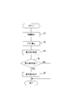
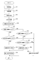
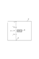
- FIG. It is a flowchart showing the execution determination process which the collision avoidance assistance apparatus 1 performs. It is a flowchart showing the condition setting process which the collision avoidance assistance apparatus 1 performs. It is explanatory drawing showing the position P and range (alpha) of the target 29 in the image 27.
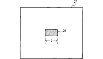
- FIG. 5A is an explanatory diagram showing the size S in the horizontal direction of the image 27 of the target 29, and
- FIG. 5B is an explanatory diagram showing the size S in the vertical direction of the image 27 of the target 29. It is explanatory drawing showing the own vehicle 31, the target 29, and the distance D.
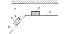
- 10 is an explanatory diagram showing a positional relationship between a host vehicle 31, a target 29, and an overhead structure 37 in a situation A.
- 10 is an explanatory diagram showing a positional relationship among a host vehicle 31, a target 29, and a road surface structure 39 in a situation B.
- FIG. 10 is an explanatory diagram showing a positional relationship between a host vehicle 31, a target 29, and an overhead structure 37 in a situation A.
- the collision avoidance assistance device 1 is an in-vehicle device mounted on a vehicle. Below, the vehicle carrying the collision avoidance assistance apparatus 1 is set as the own vehicle.
- the collision avoidance assistance device 1 includes an image sensor 3, a millimeter wave radar 5, a control ECU 7, and a brake ECU 9.
- the image sensor 3 captures a landscape in front of the host vehicle and generates an image.
- the millimeter wave radar 5 detects a target in front of the host vehicle (for example, another vehicle, a pedestrian, a roadside object, an obstacle, etc.) by transmitting and receiving a radar wave of a frequency-modulated millimeter wave band. Further, the millimeter wave radar 5 can measure the distance from the host vehicle to the target, and can specify the orientation of the target with reference to the host vehicle.
- the control ECU 7 is a known computer including a CPU, a RAM, a ROM, and the like.
- the control ECU 7 executes processing to be described later by a program stored in the ROM.
- the control ECU 7 functionally includes a target detection unit 11, a determination unit 13, a process execution unit 15, an image acquisition unit 17, an image recognition unit 19, a position P acquisition unit 21, a size RS estimation unit 23, and an execution condition setting.
- a unit 25 is provided. The function of each unit will be described later.
- the brake ECU 9 is a known computer including a CPU, a RAM, a ROM, and the like.
- the brake ECU 9 executes processing to be described later according to a program stored in the ROM. That is, the brake ECU 9 performs an automatic brake process when an execution instruction to be described later is received from the control ECU 7.
- automatic braking is an example of collision avoidance support processing.
- step S ⁇ b> 1 of FIG. 2 the target detection unit 11 uses the millimeter wave radar 5 to detect a target ahead of the host vehicle.
- step S2 the determination unit 13 repeatedly calculates the collision allowance time (TTC) of the target detected in step S1.
- TTC is a value obtained by dividing the distance D from the host vehicle to the target by the relative speed V of the target with respect to the host vehicle.
- the determination unit 13 acquires the distance D and the relative velocity V from the detection result of the millimeter wave radar 5, and calculates the TTC using them.
- step S3 the determination unit 13 acquires the execution condition set at that time.
- the execution condition is a condition that “the ratio r of TTCs having a value equal to or less than the reference value I among the TTCs acquired a plurality of times is equal to or greater than the ratio threshold R”.
- the execution condition is set by an execution condition setting process described later.
- step S4 the determination unit 13 determines whether or not the TTC acquired a plurality of times in step S2 satisfies the execution condition acquired in step S3. That is, the determination unit 13 calculates the ratio r for the TTC acquired a plurality of times in step S2, and determines whether the ratio r is equal to or greater than the ratio threshold R.
- the ratio r is N1 / N.
- the determination unit 13 determines whether the N1 / N is equal to or greater than the ratio threshold value R.
- step S5 the process execution unit 15 outputs an execution instruction.
- the brake ECU 9 performs an automatic brake process when receiving the execution instruction.
- step S ⁇ b> 11 of FIG. 3 the image acquisition unit 17 acquires an image ahead of the host vehicle using the image sensor 3.
- the vertical direction in this image matches the actual vertical direction in the photographed landscape. In other words, the target above the landscape is present above the image, and the target below the landscape is below the image.
- step S12 the image recognition unit 19 recognizes a target in the image acquired in step S11 by a known image recognition technique.
- step S13 the position P acquisition unit 21 acquires the position P in the vertical direction of the target recognized in step S12 in the image acquired in step S11.
- 27 is the image acquired in step S1
- 29 is the target recognized in step S12.
- the vertical axis in the image 27 is taken as the Y axis.
- a coordinate on the Y axis of the target 29 is defined as a position P.
- the position P is a position based on a fixed point (for example, the lower end) in the image 27.
- step S14 the size RS estimation unit 23 first acquires the size S in the target image recognized in step S12.
- the size S is an apparent size in the horizontal direction of the target 29 on the image 27 (a size represented by the number of pixels in the horizontal direction in the image 27).
- the size S may be the apparent size of the target 29 on the image 27 in the vertical direction (the size represented by the number of pixels in the vertical direction of the image 27). Good.
- step S15 the size RS estimation unit 23 determines the actual size of the target recognized in step S12 from the size S acquired as described above and the position P acquired in step 13 above. Estimate RS. This estimation is performed as follows.
- the magnitude RS estimation unit 23 includes a map that prescribes a relationship between the position P and the distance D, and calculates the distance D by inputting the position P to this map.
- the magnitude RS estimation unit 23 includes a map that prescribes the relationship between the distance D and the magnitude S and the magnitude RS in advance, and the map calculates the distance D calculated as described above and the step S14. By inputting the acquired size S, the size RS is estimated.
- step S16 the execution condition setting unit 25 determines whether or not the position P acquired in step S13 is below a preset range ⁇ in the image acquired in step S11.
- Range ⁇ as shown in FIG. 4, the range of positions in the set vertically in the image 27 acquired in step S11, the lower limit is P L, the upper limit is a P U .
- image 27 if below the position P lower limit P L, the image acquired in the step S11, so that the position P is below the range alpha.
- the range ⁇ is a range that the position P can take when the host vehicle 31 and the target 29 are on the same flat surface. If the position P is below the range ⁇ in the image acquired in step S11, the process proceeds to step S17. Otherwise, the process proceeds to step S20.
- step S17 the execution condition setting unit 25 determines whether or not the size RS estimated in step S15 is smaller than a preset range ⁇ .
- the range ⁇ is a range of a size RS that a specific type of target can take.
- the range ⁇ in a vehicle which is an example of a target can be set to 1.3 to 2.5 m. If the magnitude RS is smaller than the lower limit value (1.3 m in the above example) in the range ⁇ , the magnitude RS is smaller than the range ⁇ . If the size RS is smaller than the range ⁇ , the process proceeds to step S18. Otherwise, the process proceeds to step S23.
- step S18 the execution condition setting unit 25 determines that the situation of the road around the host vehicle is the situation A shown in FIG.
- the situation A is a situation in which the surface 33 on which the host vehicle 31 is present and the surface 35 on which the target 29 is present in front of the host vehicle 31 form a mountain shape.
- the surface 33 is an uphill
- the surface 35 is a horizontal surface
- the surface 33 is a horizontal surface
- the surface 35 is a downhill
- the surface 33 is an uphill
- the surface 35 is a downhill.
- the uphill and downhill are the uphill and downhill for the vehicle.
- step S16 the position P is lowered, so that an affirmative determination is made in step S16. Further, since the position P is low, the distance D is calculated to be smaller than the actual value. As a result, the magnitude RS is estimated to be smaller than the actual value, so that an affirmative determination is made in step S17.
- step S19 the execution condition setting unit 25 sets the execution condition more strictly than usual. Specifically, in the execution condition that “the ratio r of TTCs whose values are equal to or smaller than the reference value I among the TTCs acquired a plurality of times is equal to or greater than the ratio threshold R”, the value of the ratio threshold R is Let R 2 be greater than the value R 1 .
- the reference value I is a fixed value.
- step S16 when a negative determination is made in step S16, the process proceeds to step S20, and in the image acquired in step S11, it is determined whether or not the position P acquired in step S13 is above a preset range ⁇ .
- the execution condition setting unit 25 determines. If the position P is above the upper limit P U (see FIG. 4) in the image acquired in step S11, the position P is above the range ⁇ in the image acquired in step S11. If the position P is above the range ⁇ in the image acquired in step S11, the process proceeds to step S21. Otherwise, the process proceeds to step S23.
- step S21 the execution condition setting unit 25 determines whether or not the size RS estimated in step S15 is larger than a preset range ⁇ . If the magnitude RS is larger than the upper limit value in the range ⁇ , the magnitude RS is larger than the range ⁇ . If the size RS is larger than the range ⁇ , the process proceeds to step S22. Otherwise, the process proceeds to step S23.
- step S22 the execution condition setting unit 25 determines that the situation of the road around the host vehicle is the situation B shown in FIG.
- the surface 33 where the host vehicle 31 exists and the surface 35 where the target 29 existing in front of the host vehicle 31 forms a valley shape.
- surface 33 is downhill
- surface 35 is a horizontal plane
- surface 33 is horizontal
- surface 35 is uphill
- surface 33 is downhill
- surface 35 is uphill.
- step S20 In the case of the situation B, since the position P becomes higher, an affirmative determination is made in step S20. Further, since the position P is high, the distance D is calculated to be larger than the actual value, and as a result, the size RS is estimated to be larger than the actual value, so that an affirmative determination is made in step S21.
- step S23 the execution condition setting unit 25 sets the execution condition to a normal one. Specifically, in the execution condition that “the ratio r of TTCs whose values are equal to or smaller than the reference value I among the TTCs acquired a plurality of times is equal to or greater than the ratio threshold R”, the value of the ratio threshold R is Let R 1 be the value.
- the reference value I is a fixed value.
- step S16 is an example of satisfying condition J1
- making an affirmative decision in step S17 is an example of satisfying condition J2
- making an affirmative decision in step S20 is an example of satisfying condition J3
- making an affirmative determination in step S21 is an example of satisfying condition J4.
- overhead structure 37 may exist in the front direction of host vehicle 31, as shown in FIG.
- the overhead structure 37 is a structure (for example, a sign, a bridge, etc.) through which the host vehicle can pass.
- the millimeter wave radar 5 detects it.
- the collision avoidance assistance device 1 makes the execution condition stricter than usual in the case of the situation A, even if the overhead structure 37 is detected, the execution of the collision avoidance assistance process can be suppressed.
- a road surface structure 39 (for example, a manhole cover) may be present in the front direction of the host vehicle 31.
- the millimeter wave radar 5 detects the road surface structure 39.
- the collision avoidance assistance device 1 makes the execution condition stricter than usual in the case of the situation B, even if the road surface structure 39 is detected, the execution of the collision avoidance assistance process can be suppressed.
- the collision avoidance assisting apparatus 1 has a condition that “the ratio r of TTCs having a value equal to or smaller than the reference value I among the TTCs acquired a plurality of times is equal to or greater than the ratio threshold R” as an execution condition. As a result, it is possible to appropriately determine whether or not to execute the collision avoidance support process.
- the collision avoidance assistance device 1 makes the execution condition stricter by increasing the ratio threshold R in step S19. As a result, the severity of the execution condition can be easily changed.
- the collision avoidance support device 1 executes automatic braking as the collision avoidance support process. As a result, the safety of the host vehicle is improved.
- the execution condition may be a condition that “TTC is equal to or less than a predetermined time threshold value T”.
- the execution condition setting unit 25 sets the time threshold T to T 2 smaller than the normal value T 1 in step S19.
- the collision avoidance assistance device 1 adds the following effects (2A), (1E) to the effects (1A), (1B), (1E). 2B).
- the collision avoidance support device 1 can appropriately determine whether or not to execute the collision avoidance support process when the execution condition is as described above.
- step S19 the time threshold T, is made smaller than the normal value T 1, strict execution condition.
- the severity of the execution condition can be easily changed.
- the collision avoidance assistance device 1 may detect a target using another means (for example, a stereo camera, a rider, etc.) instead of the millimeter wave radar 5.
- the collision avoidance assistance device 1 may execute other collision avoidance assistance processing (for example, brake assist, automatic steering, warning processing, etc.) instead of or in addition to automatic braking.
- other collision avoidance assistance processing for example, brake assist, automatic steering, warning processing, etc.
- the collision avoidance assistance device 1 performs the process of step S19 when it is determined that the situation is A, but does not perform the process of step S19 in other cases (including the situation B). May be.
- the collision avoidance assistance device 1 performs the process of step S19 when it is determined that the situation is B, but does not perform the process of step S19 in other cases (including the situation A). Also good.
- the collision avoidance assistance apparatus 1 sets a value smaller than normal as the value of the reference value I in step S19, and sets a normal value as the value of the reference value I in step S23. Also good.
- the value of the ratio threshold value R may be a fixed value, or a larger value than usual may be set in step S19.
- a system including the collision avoidance assistance device as a constituent element, a program for causing a computer to function as a control ECU or a brake ECU in the collision avoidance assistance device, and a medium on which the program is recorded The present invention can also be realized in various forms such as a collision avoidance support method.
- SYMBOLS 1 Collision avoidance assistance apparatus, 3 ... Image sensor, 5 ... Millimeter wave radar, 7 ... Control ECU, 9 ... Brake ECU, 11 ... Target detection unit, 13 ... Judgment unit, 15 ... Processing execution unit, 17 ... Image acquisition Unit: 19 ... Image recognition unit, 21 ... Position P acquisition unit, 23 ... Size RS estimation unit, 25 ... Execution condition setting unit, 27 ... Image, 29 ... Target, 31 ... Own vehicle, 33, 35 ... plane, 37 ... overhead structure, 39 ... road surface structure
Landscapes
- Engineering & Computer Science (AREA)
- Physics & Mathematics (AREA)
- Remote Sensing (AREA)
- Radar, Positioning & Navigation (AREA)
- General Physics & Mathematics (AREA)
- Transportation (AREA)
- Mechanical Engineering (AREA)
- Computer Networks & Wireless Communication (AREA)
- Automation & Control Theory (AREA)
- Theoretical Computer Science (AREA)
- Computer Vision & Pattern Recognition (AREA)
- Electromagnetism (AREA)
- Combustion & Propulsion (AREA)
- Chemical & Material Sciences (AREA)
- Multimedia (AREA)
- Geometry (AREA)
- Traffic Control Systems (AREA)
- Control Of Driving Devices And Active Controlling Of Vehicle (AREA)
- Radar Systems Or Details Thereof (AREA)
Abstract
物標を検出する物標検出ユニット(11)と、物標が実行条件を充足すると判断した場合、衝突回避支援処理を実行する処理実行ユニット(15)と、画像において物標を認識する画像認識ユニット(19)と、物標の上下方向での位置Pを取得する位置P取得ユニット(21)と、物標の実際の大きさRSを推定する大きさRS推定ユニット(23)と、条件J1及びJ2が充足される場合、又は、条件J3及びJ4が充足される場合は、それら以外の場合よりも、実行条件を厳しく設定する実行条件設定ユニット(25)とを備える衝突回避支援装置(1)。J1:前記画像において、位置Pが範囲αよりも下にあること。J2:大きさRSが範囲βよりも小さいこと。J3:前記画像において、位置Pが範囲αよりも上にあること。J4:大きさRSが範囲βよりも大きいこと。
Description
本発明は衝突回避支援装置に関する。
従来、ミリ波レーダを用いて、自車両前方の物標を検出し、検出した物標が所定の条件を充足する場合は、警報等の衝突回避支援処理を行う技術が知られている。物標のうち、マンホールの蓋等の路面構造物は、自車両が容易に乗り越えることができるものであるので、衝突回避支援処理を行う必要はない。特許文献1記載の技術では、ミリ波レーダにおける反射波の特徴から、物標の路面からの高さを推定し、その推定結果に基づき、路面構造物と、衝突回避支援処理が必要な物標とを識別する。
自車両や物標が存在する道路の傾斜によっては、検出した物標が路面構造物であるか否かを正確に識別することは困難である。その結果、路面構造物に対し、不必要な衝突回避支援処理を行うおそれがあった。本発明は、こうした問題にかんがみてなされたものであり、不必要な衝突回避支援処理の実行を抑制できる衝突支援回避装置を提供することを目的としている。
本発明の衝突回避支援装置は、自車両前方の物標を検出する物標検出ユニットと、物標検出ユニットで検出した物標が所定の実行条件を充足するか否かを判断する判断ユニットと、実行条件を充足すると判断ユニットが判断した場合、衝突回避支援処理を実行する処理実行ユニットと、自車両前方の画像を取得する画像取得ユニットと、画像において物標を認識する画像認識ユニットと、画像認識ユニットで認識した物標の画像における上下方向での位置Pを取得する位置P取得ユニットと、画像認識ユニットで認識した物標の画像における大きさS、及び位置Pから、画像認識ユニットで認識した物標の実際の大きさRSを推定する大きさRS推定ユニットと、以下の条件J1及びJ2が充足される場合、又は、以下の条件J3及びJ4が充足される場合は、それら以外の場合よりも、実行条件を厳しく設定する実行条件設定ユニットとを備える。
J1:前記画像において、位置Pが、予め設定された前記画像における上下方向での位置の範囲αよりも下にあること。
J2:大きさRSが、予め設定された大きさの範囲βよりも小さいこと。
J3:前記画像において、位置Pが、前記範囲αよりも上にあること。
J4:大きさRSが、前記範囲βよりも大きいこと。
J1:前記画像において、位置Pが、予め設定された前記画像における上下方向での位置の範囲αよりも下にあること。
J2:大きさRSが、予め設定された大きさの範囲βよりも小さいこと。
J3:前記画像において、位置Pが、前記範囲αよりも上にあること。
J4:大きさRSが、前記範囲βよりも大きいこと。
本発明の衝突回避支援装置は、物標検出ユニットで検出した物標が頭上構造物である可能性が高い場合(条件J1及びJ2が充足される場合)と、路面構造物である可能性が高い場合(条件J3及びJ4が充足される場合)とには、衝突回避支援処理を実行するための実行条件を厳しく設定する。そのことにより、不必要な衝突回避支援処理の実行を抑制できる。
本発明の実施形態を図面に基づき説明する。
<第1の実施形態>
1.衝突回避支援装置1の構成
衝突回避支援装置1の構成を、図1に基づき説明する。衝突回避支援装置1は、車両に搭載される車載装置である。以下では、衝突回避支援装置1を搭載する車両を自車両とする。衝突回避支援装置1は、画像センサ3、ミリ波レーダ5、制御ECU7、及びブレーキECU9を備える。
<第1の実施形態>
1.衝突回避支援装置1の構成
衝突回避支援装置1の構成を、図1に基づき説明する。衝突回避支援装置1は、車両に搭載される車載装置である。以下では、衝突回避支援装置1を搭載する車両を自車両とする。衝突回避支援装置1は、画像センサ3、ミリ波レーダ5、制御ECU7、及びブレーキECU9を備える。
画像センサ3は、自車両の前方の風景を撮影し、画像を生成する。ミリ波レーダ5は、周波数変調されたミリ波帯のレーダ波を送受信することにより、自車両前方の物標(例えば、他の車両、歩行者、路側物、障害物等)を検出する。また、ミリ波レーダ5は、自車両から物標までの距離を測定可能であり、自車両を基準とする物標の方位を特定可能である。
制御ECU7は、CPU、RAM、ROM等を備える公知のコンピュータである。制御ECU7は、ROMに記憶されたプログラムにより、後述する処理を実行する。制御ECU7は、機能的に、物標検出ユニット11、判断ユニット13、処理実行ユニット15、画像取得ユニット17、画像認識ユニット19、位置P取得ユニット21、大きさRS推定ユニット23、及び実行条件設定ユニット25を備える。各ユニットの機能は後述する。
ブレーキECU9は、CPU、RAM、ROM等を備える公知のコンピュータである。ブレーキECU9は、ROMに記憶されたプログラムにより、後述する処理を実行する。すなわち、ブレーキECU9は、後述する実行指示を制御ECU7から受信したとき、自動ブレーキの処理を行う。なお、自動ブレーキは衝突回避支援処理の一例である。
2.衝突回避支援装置1が実行する処理
(2-1)実行判断処理
衝突回避支援装置1(特に制御ECU7)が所定時間ごとに繰り返し行う実行判断処理を図2に基づき説明する。図2のステップS1では、物標検出ユニット11が、ミリ波レーダ5を用いて、自車両前方の物標を検出する。
(2-1)実行判断処理
衝突回避支援装置1(特に制御ECU7)が所定時間ごとに繰り返し行う実行判断処理を図2に基づき説明する。図2のステップS1では、物標検出ユニット11が、ミリ波レーダ5を用いて、自車両前方の物標を検出する。
ステップS2では、判断ユニット13が、前記ステップS1で検出した物標の衝突余裕時間(TTC)を繰り返し算出する。TTCは、自車両から物標までの距離Dを、自車両を基準とする物標の相対速度Vで割った値である。判断ユニット13は、ミリ波レーダ5の検出結果から、距離D及び相対速度Vを取得し、それらを用いてTTCを算出する。
ステップS3では、その時点で設定されている実行条件を、判断ユニット13が取得する。実行条件とは、“複数回取得されたTTCのうち、値が基準値I以下であるTTCの割合rが、割合閾値R以上である”という条件である。なお、実行条件は、後述する実行条件設定処理により設定される。
ステップS4では、前記ステップS2で複数回取得したTTCが、前記ステップS3で取得した実行条件を充足するか否かを、判断ユニット13が判断する。すなわち、判断ユニット13は、前記ステップS2で複数回取得したTTCについて、割合rを算出し、その割合rが割合閾値R以上であるか否かを判断する。
例えば、前記ステップS2で取得したTTCの総数をNとし、そのうち、値が基準値I以下であるTTCの数がN1であったとすると、割合rは、N1/Nとなる。判断ユニット13は、そのN1/Nが、割合閾値R以上であるか否かを判断する。
実行条件を充足すると判断した場合はステップS5に進み、充足しないと判断した場合は本処理を終了する。
ステップS5では、処理実行ユニット15が実行指示を出力する。なお、前述したとおり、ブレーキECU9は、その実行指示を受信したとき、自動ブレーキの処理を行う。
ステップS5では、処理実行ユニット15が実行指示を出力する。なお、前述したとおり、ブレーキECU9は、その実行指示を受信したとき、自動ブレーキの処理を行う。
(2-2)実行条件設定処理
衝突回避支援装置1(特に制御ECU7)が所定時間ごとに繰り返し行う実行条件設定処理を図3~図8に基づき説明する。図3のステップS11では、画像取得ユニット17が、画像センサ3を用いて自車両前方の画像を取得する。この画像における上下方向は、撮影した風景における実際の上下方向と一致する。すなわち、風景において上方にある物標は、画像においても上方に存在し、風景において下方に存在する物標は、画像においても下方に存在する。
衝突回避支援装置1(特に制御ECU7)が所定時間ごとに繰り返し行う実行条件設定処理を図3~図8に基づき説明する。図3のステップS11では、画像取得ユニット17が、画像センサ3を用いて自車両前方の画像を取得する。この画像における上下方向は、撮影した風景における実際の上下方向と一致する。すなわち、風景において上方にある物標は、画像においても上方に存在し、風景において下方に存在する物標は、画像においても下方に存在する。
ステップS12では、画像認識ユニット19が、前記ステップS11で取得した画像において、周知の画像認識技術により、物標を認識する。
ステップS13は、前記ステップS12で認識した物標の、前記ステップS11で取得した画像における上下方向での位置Pを、位置P取得ユニット21が取得する。この処理を図4に基づき具体的に説明する。図4において27は前記ステップS1で取得した画像であり、29は前記ステップS12で認識した物標である。画像27における上下方向の軸をY軸とする。物標29のY軸における座標を位置Pとする。位置Pは、画像27における固定点(例えば下端)を基準とする位置である。
図3に戻り、ステップS14では、大きさRS推定ユニット23が、まず、前記ステップS12で認識した物標の画像における大きさSを取得する。この大きさSとは、図5Aに示すように、画像27上における物標29の横方向における見かけの大きさ(画像27における横方向での画素数で表される大きさ)である。
なお、大きさSは、図5Bに示すように、画像27上における物標29の縦方向における見かけの大きさ(画像27における縦方向での画素数で表される大きさ)であってもよい。
次に、ステップS15では、大きさRS推定ユニット23は、上記のように取得した大きさSと、前記ステップ13で取得した位置Pとから、前記ステップS12で認識した物標の実際の大きさRSを推定する。この推定は以下のように行う。
図6に示すように、自車両31と物標29とが同一平坦面上にあると仮定すると、自車両から物標までの距離Dと、位置Pとは1:1に対応する(距離Dが大きいほど、画像における位置Pは高くなる)。大きさRS推定ユニット23は、予め、位置Pと距離Dとの関係を規定するマップを備えており、このマップに位置Pを入力することで、距離Dを算出する。
また、距離D及び大きさSが決まれば、大きさRSも一義的に決まる。大きさRS推定ユニット23は、予め、距離D及び大きさSと、大きさRSとの関係を規定するマップを備えており、このマップに上記のように算出した距離D、及び前記ステップS14で取得した大きさSを入力することで、大きさRSを推定する。
ステップS16では、前記ステップS11で取得した画像において、前記ステップS13で取得した位置Pが、予め設定された範囲αよりも下にあるか否かを実行条件設定ユニット25が判断する。範囲αとは、図4に示すように、前記ステップS11で取得した画像27内で設定された上下方向での位置の範囲であり、その下限はPLであり、その上限はPUである。画像27において、位置Pが下限PLより下にあれば、前記ステップS11で取得した画像において、位置Pが範囲αよりも下にあることになる。なお、範囲αは、図6に示すように、同一平坦面上に自車両31及び物標29があるときに位置Pが取り得る範囲である。前記ステップS11で取得した画像において、位置Pが範囲αより下にある場合はステップS17に進み、それ以外の場合はステップS20に進む。
ステップS17では、前記ステップS15で推定した大きさRSが、予め設定された範囲βよりも小さいか否かを実行条件設定ユニット25が判断する。範囲βとは、特定の種類の物標が取り得る大きさRSの範囲である。例えば、物標の一例である車両における範囲βは、1.3~2.5mとすることができる。大きさRSが、範囲βにおける下限値(上の例では1.3m)より小さければ、大きさRSは範囲βより小さいことになる。大きさRSが範囲βより小さい場合はステップS18に進み、それ以外の場合はステップS23に進む。
ステップS18では、自車両の周囲の道路の状況が、図7に示す状況Aであると実行条件設定ユニット25が判断する。この状況Aは、自車両31が存在する面33と、自車両31の前方にある物標29が存在する面35とが、山型を構成する状況である。状況Aには、面33が上り坂であり、面35が水平面であるケース、面33が水平面であり、面35が下り坂であるケース、面33が上り坂であり、面35が下り坂であるケース等が含まれる。なお、前記の登り坂、下り坂とは自車両にとっての登り坂、下り坂である。
なお、状況Aである場合、位置Pは低くなるので前記ステップS16では肯定判断される。また、位置Pが低いので距離Dが実際より小さく算出され、その結果、大きさRSは実際より小さく推定されるので、前記ステップS17では肯定判断される。
ステップS19では、実行条件設定ユニット25が、実行条件を通常より厳しく設定する。具体的には、“複数回取得されたTTCのうち、値が基準値I以下であるTTCの割合rが、割合閾値R以上である”という実行条件において、割合閾値Rの値を、通常の値であるR1よりも大きいR2とする。なお、基準値Iは固定値である。
一方、前記ステップS16で否定判断した場合はステップS20に進み、前記ステップS11で取得した画像において、前記ステップS13で取得した位置Pが、予め設定された範囲αよりも上にあるか否かを実行条件設定ユニット25が判断する。前記ステップS11で取得した画像において、位置Pが上限PU(図4参照)より上にあれば、前記ステップS11で取得した画像において、位置Pが範囲αよりも上にあることになる。前記ステップS11で取得した画像において、位置Pが範囲αより上にある場合はステップS21に進み、それ以外の場合はステップS23に進む。
ステップS21では、前記ステップS15で推定した大きさRSが、予め設定された範囲βよりも大きいか否かを実行条件設定ユニット25が判断する。大きさRSが、範囲βにおける上限値より大きければ、大きさRSは範囲βより大きいことになる。大きさRSが範囲βより大きい場合はステップS22に進み、それ以外の場合はステップS23に進む。
ステップS22では、自車両の周囲の道路の状況が、図8に示す状況Bであると実行条件設定ユニット25が判断する。この状況Bは、自車両31が存在する面33と、自車両31の前方にある物標29が存在する面35とが、谷型を構成する状況である。状況Bには、面33が下り坂であり、面35が水平面であるケース、面33が水平面であり、面35が登り坂であるケース、面33が下り坂であり、面35が登り坂であるケース等が含まれる。
なお、状況Bである場合、位置Pは高くなるので前記ステップS20では肯定判断される。また、位置Pが高いので距離Dが実際より大きく算出され、その結果、大きさRSは実際より大きく推定されるので、前記ステップS21では肯定判断される。
ステップS23では、実行条件設定ユニット25が、実行条件を通常のものに設定する。具体的には、“複数回取得されたTTCのうち、値が基準値I以下であるTTCの割合rが、割合閾値R以上である”という実行条件において、割合閾値Rの値を、通常の値であるR1とする。なお、基準値Iは固定値である。
なお、前記ステップS16で肯定判断することは条件J1を充足することの一例であり、前記ステップS17で肯定判断することは条件J2を充足することの一例であり、前記ステップS20で肯定判断することは条件J3を充足することの一例であり、前記ステップS21で肯定判断することは条件J4を充足することの一例である。
3.衝突回避支援装置1が奏する効果
(1A)状況Aでは、図7に示すように、頭上構造物37が自車両31の正面方向に存在することがある。頭上構造物37とは、その下を自車両が通過できる構造物(例えば、標識、橋等)である。頭上構造物37が存在する場合、ミリ波レーダ5はそれを検出する。しかしながら、衝突回避支援装置1は、状況Aの場合、実行条件を通常より厳しくするので、頭上構造物37を検出しても、それに対する衝突回避支援処理の実行を抑制することができる。
(1A)状況Aでは、図7に示すように、頭上構造物37が自車両31の正面方向に存在することがある。頭上構造物37とは、その下を自車両が通過できる構造物(例えば、標識、橋等)である。頭上構造物37が存在する場合、ミリ波レーダ5はそれを検出する。しかしながら、衝突回避支援装置1は、状況Aの場合、実行条件を通常より厳しくするので、頭上構造物37を検出しても、それに対する衝突回避支援処理の実行を抑制することができる。
(1B)状況Bでは、図8に示すように、路面構造物39(例えばマンホールの蓋等)が自車両31の正面方向に存在することがある。この場合、ミリ波レーダ5は路面構造物39を検出する。しかしながら、衝突回避支援装置1は、状況Bの場合、実行条件を通常より厳しくするので、路面構造物39を検出しても、それに対する衝突回避支援処理の実行を抑制することができる。
(1C)衝突回避支援装置1は、実行条件として、“複数回取得されたTTCのうち、値が基準値I以下であるTTCの割合rが、割合閾値R以上である”という条件である。そのことにより、衝突回避支援処理を実行するか否かを適切に判断することができる。
(1D)衝突回避支援装置1は、前記ステップS19において、割合閾値Rを通常より大きくすることで、実行条件を厳しくする。そのことにより、実行条件の厳しさを容易に変更することができる。
(1E)衝突回避支援装置1は、衝突回避支援処理として自動ブレーキを実行する。そのことにより、自車両の安全性が向上する。
<その他の実施形態>
以上、本発明の実施形態について説明したが、本発明は上記実施形態に限定されることなく、種々の形態を採り得る。
以上、本発明の実施形態について説明したが、本発明は上記実施形態に限定されることなく、種々の形態を採り得る。
(1)実行条件は、“TTCが所定の時間閾値T以下である”という条件であってもよい。この場合、実行条件設定ユニット25は、前記ステップS19において、時間閾値Tを、通常の値T1よりも小さいT2に設定する。また、実行条件設定ユニット25は、前記ステップS23において、時間閾値Tを、通常の値T1とする。
実行条件の内容、及びその設定方法が上記のものである場合、衝突回避支援装置1は、前記(1A)、(1B)、(1E)の効果に加えて、以下の効果(2A)、(2B)を奏することができる。
(2A)衝突回避支援装置1は、実行条件が上記のものであることにより、衝突回避支援処理を実行するか否かを適切に判断することができる。
(2B)衝突回避支援装置1は、前記ステップS19において、時間閾値Tを、通常の値T1よりも小さくすることで、実行条件を厳しくする。そのことにより、実行条件の厳しさを容易に変更することができる。
(2)衝突回避支援装置1は、ミリ波レーダ5に代えて、他の手段(例えば、ステレオカメラ、ライダー等)を用いて物標を検出してもよい。
(3)衝突回避支援装置1は、自動ブレーキに代えて、あるいはそれに加えて、他の衝突回避支援処理(例えば、ブレーキアシスト、自動操舵、警報処理等)を実行してもよい。
(4)衝突回避支援装置1は、状況Aであると判断した場合は前記ステップS19の処理を行うが、その他の場合(状況Bである場合も含む)は、前記ステップS19の処理を行わなくてもよい。また、衝突回避支援装置1は、状況Bであると判断した場合は前記ステップS19の処理を行うが、その他の場合(状況Aである場合も含む)は、前記ステップS19の処理を行わなくてもよい。
(5)衝突回避支援装置1は、前記ステップS19において、基準値Iの値として、通常よりも小さい値を設定し、前記ステップS23において、基準値Iの値として、通常の値を設定してもよい。この場合、割合閾値Rの値は、固定値であってもよいし、前記ステップS19において、通常より大きい値を設定してもよい。
(6)上記実施形態における1つの構成要素が有する機能を複数の構成要素として分散させたり、複数の構成要素が有する機能を1つの構成要素に統合させたりしてもよい。また、上記実施形態の構成の少なくとも一部を、同様の機能を有する公知の構成に置き換えてもよい。また、上記実施形態の構成の一部を省略してもよい。また、上記実施形態の構成の少なくとも一部を、他の上記実施形態の構成に対して付加又は置換してもよい。なお、特許請求の範囲に記載した文言のみによって特定される技術思想に含まれるあらゆる態様が本発明の実施形態である。
(7)上述した衝突回避支援装置の他、当該衝突回避支援装置を構成要素とするシステム、当該衝突回避支援装置における制御ECU又はブレーキECUとしてコンピュータを機能させるためのプログラム、このプログラムを記録した媒体、衝突回避支援方法等、種々の形態で本発明を実現することもできる。
1…衝突回避支援装置、3…画像センサ、5…ミリ波レーダ、7…制御ECU、9…ブレーキECU、11…物標検出ユニット、13…判断ユニット、15…処理実行ユニット、17…画像取得ユニット、19…画像認識ユニット、21…位置P取得ユニット、23…大きさRS推定ユニット、25…実行条件設定ユニット、27…画像、29…物標、31…自車両、33、35…面、37…頭上構造物、39…路面構造物
Claims (5)
- 自車両前方の物標を検出する物標検出ユニット(11)と、
前記物標検出ユニットで検出した物標が所定の実行条件を充足するか否かを判断する判断ユニット(13)と、
前記実行条件を充足すると前記判断ユニットが判断した場合、衝突回避支援処理を実行する処理実行ユニット(15)と、
自車両前方の画像を取得する画像取得ユニット(17)と、
前記画像において物標を認識する画像認識ユニット(19)と、
前記画像認識ユニットで認識した物標の前記画像における上下方向での位置Pを取得する位置P取得ユニット(21)と、
前記画像認識ユニットで認識した物標の前記画像における大きさS、及び前記位置Pから、前記画像認識ユニットで認識した物標の実際の大きさRSを推定する大きさRS推定ユニット(23)と、
以下の条件J1及びJ2が充足される場合、又は、以下の条件J3及びJ4が充足される場合は、それら以外の場合よりも、前記実行条件を厳しく設定する実行条件設定ユニット(25)と、
を備える衝突回避支援装置(1)。
J1:前記画像において、前記位置Pが、予め設定された前記画像における上下方向での位置の範囲αよりも下にあること。
J2:前記大きさRSが、予め設定された大きさの範囲βよりも小さいこと。
J3:前記画像において、前記位置Pが、前記範囲αよりも上にあること。
J4:前記大きさRSが、前記範囲βよりも大きいこと。 - 前記実行条件は、前記物標の衝突余裕時間が所定の時間閾値以下であるという条件、又は、複数回取得された前記衝突余裕時間のうち、値が基準値以下である前記衝突余裕時間の割合が、所定の割合閾値以上であるという条件である請求項1に記載の衝突回避支援装置。
- 前記実行条件設定ユニットは、前記条件J1及びJ2が充足される場合、又は、前記条件J3及びJ4が充足される場合は、それら以外の場合よりも、前記時間閾値を小さくするか、前記割合閾値を大きくする請求項2に記載の衝突回避支援装置。
- 前記物標検出ユニットは、ミリ波レーダを用いて物標を検出する請求項1~3のいずれか1項に記載の衝突回避支援装置。
- 前記衝突回避支援処理は、ブレーキアシスト、自動ブレーキ、自動操舵、及び警報処理のうちの1以上である請求項1~3のいずれか1項に記載の衝突回避支援装置。
Priority Applications (1)
| Application Number | Priority Date | Filing Date | Title |
|---|---|---|---|
| US15/562,177 US10442430B2 (en) | 2015-04-02 | 2016-03-18 | Collision avoidance assistance device |
Applications Claiming Priority (2)
| Application Number | Priority Date | Filing Date | Title |
|---|---|---|---|
| JP2015-075827 | 2015-04-02 | ||
| JP2015075827A JP2016197018A (ja) | 2015-04-02 | 2015-04-02 | 衝突回避支援装置 |
Publications (1)
| Publication Number | Publication Date |
|---|---|
| WO2016158491A1 true WO2016158491A1 (ja) | 2016-10-06 |
Family
ID=57004254
Family Applications (1)
| Application Number | Title | Priority Date | Filing Date |
|---|---|---|---|
| PCT/JP2016/058680 Ceased WO2016158491A1 (ja) | 2015-04-02 | 2016-03-18 | 衝突回避支援装置 |
Country Status (3)
| Country | Link |
|---|---|
| US (1) | US10442430B2 (ja) |
| JP (1) | JP2016197018A (ja) |
| WO (1) | WO2016158491A1 (ja) |
Cited By (1)
| Publication number | Priority date | Publication date | Assignee | Title |
|---|---|---|---|---|
| EP3438696A1 (en) * | 2017-08-04 | 2019-02-06 | Aptiv Technologies Limited | Automated vehicle tracking system |
Families Citing this family (3)
| Publication number | Priority date | Publication date | Assignee | Title |
|---|---|---|---|---|
| JP6988200B2 (ja) * | 2017-06-29 | 2022-01-05 | 株式会社デンソー | 車両制御装置 |
| JP7122101B2 (ja) * | 2017-11-07 | 2022-08-19 | 株式会社Subaru | 車両用障害物検知装置 |
| JP7178408B2 (ja) * | 2018-05-23 | 2022-11-25 | パナソニック インテレクチュアル プロパティ コーポレーション オブ アメリカ | 異常検出装置、異常検出システム及び制御方法 |
Citations (3)
| Publication number | Priority date | Publication date | Assignee | Title |
|---|---|---|---|---|
| JPH11203458A (ja) * | 1998-01-13 | 1999-07-30 | Nissan Motor Co Ltd | 道路形状認識装置 |
| JP2008186384A (ja) * | 2007-01-31 | 2008-08-14 | Toyota Motor Corp | 車両の制御装置 |
| JP2014164461A (ja) * | 2013-02-25 | 2014-09-08 | Denso Corp | 歩行者検出装置、および歩行者検出方法 |
Family Cites Families (12)
| Publication number | Priority date | Publication date | Assignee | Title |
|---|---|---|---|---|
| JP3651745B2 (ja) * | 1998-03-17 | 2005-05-25 | 株式会社東芝 | 物体領域追跡装置および物体領域追跡方法 |
| JP3664110B2 (ja) * | 2001-07-04 | 2005-06-22 | 日産自動車株式会社 | 物体種別判定装置及び物体種別判定方法 |
| US7389171B2 (en) * | 2003-12-22 | 2008-06-17 | Ford Global Technologies Llc | Single vision sensor object detection system |
| JP4428208B2 (ja) * | 2004-11-16 | 2010-03-10 | 株式会社デンソー | 車両用物体認識装置 |
| JP4322913B2 (ja) * | 2006-12-19 | 2009-09-02 | 富士通テン株式会社 | 画像認識装置、画像認識方法および電子制御装置 |
| JP4775391B2 (ja) * | 2008-03-18 | 2011-09-21 | 株式会社デンソー | 障害物検出装置 |
| JP4905512B2 (ja) | 2009-07-09 | 2012-03-28 | 株式会社デンソー | 物標情報推定装置 |
| JP5537492B2 (ja) * | 2011-05-12 | 2014-07-02 | 富士重工業株式会社 | 環境認識装置 |
| WO2014024336A1 (ja) * | 2012-08-09 | 2014-02-13 | トヨタ自動車株式会社 | 物体検出装置及び運転支援装置 |
| JP6212880B2 (ja) | 2013-03-04 | 2017-10-18 | 株式会社デンソー | 物標認識装置 |
| US9545923B2 (en) * | 2014-07-14 | 2017-01-17 | Palo Alto Research Center Incorporated | Metamaterial-based object-detection system |
| US9568611B2 (en) * | 2014-08-20 | 2017-02-14 | Nec Corporation | Detecting objects obstructing a driver's view of a road |
-
2015
- 2015-04-02 JP JP2015075827A patent/JP2016197018A/ja active Pending
-
2016
- 2016-03-18 US US15/562,177 patent/US10442430B2/en active Active
- 2016-03-18 WO PCT/JP2016/058680 patent/WO2016158491A1/ja not_active Ceased
Patent Citations (3)
| Publication number | Priority date | Publication date | Assignee | Title |
|---|---|---|---|---|
| JPH11203458A (ja) * | 1998-01-13 | 1999-07-30 | Nissan Motor Co Ltd | 道路形状認識装置 |
| JP2008186384A (ja) * | 2007-01-31 | 2008-08-14 | Toyota Motor Corp | 車両の制御装置 |
| JP2014164461A (ja) * | 2013-02-25 | 2014-09-08 | Denso Corp | 歩行者検出装置、および歩行者検出方法 |
Cited By (2)
| Publication number | Priority date | Publication date | Assignee | Title |
|---|---|---|---|---|
| EP3438696A1 (en) * | 2017-08-04 | 2019-02-06 | Aptiv Technologies Limited | Automated vehicle tracking system |
| CN109383506A (zh) * | 2017-08-04 | 2019-02-26 | 安波福技术有限公司 | 自动化车辆跟踪系统 |
Also Published As
| Publication number | Publication date |
|---|---|
| US20180086337A1 (en) | 2018-03-29 |
| JP2016197018A (ja) | 2016-11-24 |
| US10442430B2 (en) | 2019-10-15 |
Similar Documents
| Publication | Publication Date | Title |
|---|---|---|
| JP5870908B2 (ja) | 車両の衝突判定装置 | |
| JP6536521B2 (ja) | 物体検知装置及び物体検知方法 | |
| JP6404722B2 (ja) | 車両の走行制御装置 | |
| EP2741270B1 (en) | Driving assistance apparatus and driving assistance method | |
| JP6132359B2 (ja) | 走行区画線認識装置 | |
| US10665107B2 (en) | Moving object control apparatus and method of controlling moving object | |
| JP5966965B2 (ja) | 車線境界線逸脱抑制装置及び車線境界線逸脱抑制方法 | |
| JP5846109B2 (ja) | 衝突判定装置及び衝突回避システム | |
| JP6819281B2 (ja) | 衝突判定装置、および、衝突判定システム | |
| JP6096723B2 (ja) | 走行区画線認識装置及び走行区画線認識プログラム | |
| JP6856452B2 (ja) | 物標判定装置及び運転支援システム | |
| US10871565B2 (en) | Object detection apparatus and object detection method | |
| JP6330160B2 (ja) | 物体認識装置 | |
| JP6140658B2 (ja) | 走行区画線認識装置、走行区画線認識プログラム | |
| CN107408346B (zh) | 车辆控制装置以及车辆控制方法 | |
| US20180012083A1 (en) | Demarcation line recognition apparatus | |
| WO2017111135A1 (ja) | 走行支援装置及び走行支援方法 | |
| US10996317B2 (en) | Object detection apparatus and object detection method | |
| WO2017104503A1 (ja) | 移動体制御装置及び移動体制御方法 | |
| JP6408935B2 (ja) | 走行区画線認識装置 | |
| JP6429360B2 (ja) | 物体検出装置 | |
| US10068142B2 (en) | Detection apparatus, detection method, driving assistance apparatus, and driving assistance method | |
| WO2016158491A1 (ja) | 衝突回避支援装置 | |
| JP5298104B2 (ja) | 車両の制御装置 | |
| JP6617696B2 (ja) | 車両制御装置、車両制御方法 |
Legal Events
| Date | Code | Title | Description |
|---|---|---|---|
| 121 | Ep: the epo has been informed by wipo that ep was designated in this application |
Ref document number: 16772374 Country of ref document: EP Kind code of ref document: A1 |
|
| WWE | Wipo information: entry into national phase |
Ref document number: 15562177 Country of ref document: US |
|
| NENP | Non-entry into the national phase |
Ref country code: DE |
|
| 122 | Ep: pct application non-entry in european phase |
Ref document number: 16772374 Country of ref document: EP Kind code of ref document: A1 |