WO2016158437A1 - 炭化水素用の脱水素触媒、水素の製造システム及び水素の製造方法 - Google Patents
炭化水素用の脱水素触媒、水素の製造システム及び水素の製造方法 Download PDFInfo
- Publication number
- WO2016158437A1 WO2016158437A1 PCT/JP2016/058444 JP2016058444W WO2016158437A1 WO 2016158437 A1 WO2016158437 A1 WO 2016158437A1 JP 2016058444 W JP2016058444 W JP 2016058444W WO 2016158437 A1 WO2016158437 A1 WO 2016158437A1
- Authority
- WO
- WIPO (PCT)
- Prior art keywords
- dehydrogenation catalyst
- dehydrogenation
- carrier
- hydrogen
- tio
- Prior art date
- Legal status (The legal status is an assumption and is not a legal conclusion. Google has not performed a legal analysis and makes no representation as to the accuracy of the status listed.)
- Ceased
Links
Images




Classifications
-
- B—PERFORMING OPERATIONS; TRANSPORTING
- B01—PHYSICAL OR CHEMICAL PROCESSES OR APPARATUS IN GENERAL
- B01J—CHEMICAL OR PHYSICAL PROCESSES, e.g. CATALYSIS OR COLLOID CHEMISTRY; THEIR RELEVANT APPARATUS
- B01J23/00—Catalysts comprising metals or metal oxides or hydroxides, not provided for in group B01J21/00
- B01J23/38—Catalysts comprising metals or metal oxides or hydroxides, not provided for in group B01J21/00 of noble metals
- B01J23/40—Catalysts comprising metals or metal oxides or hydroxides, not provided for in group B01J21/00 of noble metals of the platinum group metals
- B01J23/42—Platinum
-
- B—PERFORMING OPERATIONS; TRANSPORTING
- B01—PHYSICAL OR CHEMICAL PROCESSES OR APPARATUS IN GENERAL
- B01J—CHEMICAL OR PHYSICAL PROCESSES, e.g. CATALYSIS OR COLLOID CHEMISTRY; THEIR RELEVANT APPARATUS
- B01J37/00—Processes, in general, for preparing catalysts; Processes, in general, for activation of catalysts
- B01J37/02—Impregnation, coating or precipitation
- B01J37/0201—Impregnation
- B01J37/0207—Pretreatment of the support
-
- C—CHEMISTRY; METALLURGY
- C01—INORGANIC CHEMISTRY
- C01B—NON-METALLIC ELEMENTS; COMPOUNDS THEREOF; METALLOIDS OR COMPOUNDS THEREOF NOT COVERED BY SUBCLASS C01C
- C01B3/00—Hydrogen; Gaseous mixtures containing hydrogen; Separation of hydrogen from mixtures containing it; Purification of hydrogen; Reversible storage of hydrogen
- C01B3/02—Production of hydrogen; Production of gaseous mixtures containing hydrogen
- C01B3/22—Production of hydrogen; Production of gaseous mixtures containing hydrogen by decomposition of gaseous or liquid organic compounds
- C01B3/24—Production of hydrogen; Production of gaseous mixtures containing hydrogen by decomposition of gaseous or liquid organic compounds of hydrocarbons
- C01B3/26—Production of hydrogen; Production of gaseous mixtures containing hydrogen by decomposition of gaseous or liquid organic compounds of hydrocarbons using catalysts
-
- H—ELECTRICITY
- H01—ELECTRIC ELEMENTS
- H01M—PROCESSES OR MEANS, e.g. BATTERIES, FOR THE DIRECT CONVERSION OF CHEMICAL ENERGY INTO ELECTRICAL ENERGY
- H01M8/00—Fuel cells; Manufacture thereof
- H01M8/06—Combination of fuel cells with means for production of reactants or for treatment of residues
- H01M8/0606—Combination of fuel cells with means for production of reactants or for treatment of residues with means for production of gaseous reactants
- H01M8/0612—Combination of fuel cells with means for production of reactants or for treatment of residues with means for production of gaseous reactants from carbon-containing material
-
- Y—GENERAL TAGGING OF NEW TECHNOLOGICAL DEVELOPMENTS; GENERAL TAGGING OF CROSS-SECTIONAL TECHNOLOGIES SPANNING OVER SEVERAL SECTIONS OF THE IPC; TECHNICAL SUBJECTS COVERED BY FORMER USPC CROSS-REFERENCE ART COLLECTIONS [XRACs] AND DIGESTS
- Y02—TECHNOLOGIES OR APPLICATIONS FOR MITIGATION OR ADAPTATION AGAINST CLIMATE CHANGE
- Y02E—REDUCTION OF GREENHOUSE GAS [GHG] EMISSIONS, RELATED TO ENERGY GENERATION, TRANSMISSION OR DISTRIBUTION
- Y02E60/00—Enabling technologies; Technologies with a potential or indirect contribution to GHG emissions mitigation
- Y02E60/30—Hydrogen technology
- Y02E60/50—Fuel cells
Definitions
- the present invention relates to a dehydrogenation catalyst for hydrocarbons, a hydrogen production system, and a hydrogen production method.
- naphthenic hydrocarbons cyclic hydrocarbons
- naphthenic hydrocarbons are generated by hydrogenation of aromatic hydrocarbons.
- This naphthenic hydrocarbon is transported to a hydrogen consumption area or stored in the consumption area.
- hydrogen and aromatic hydrocarbons are generated by dehydrogenation of naphthenic hydrocarbons.
- This hydrogen is supplied to the fuel cell.
- Naphthenic hydrocarbons are liquid at room temperature, have a smaller volume than hydrogen gas, are less reactive than hydrogen gas, and are safe. Therefore, naphthenic hydrocarbons are more suitable for transportation and storage than hydrogen gas.
- Non-Patent Document 1 As a dehydrogenation catalyst for naphthenic hydrocarbons, a catalyst in which a platinum-rhenium bimetal is supported on an alumina carrier is known (see Non-Patent Document 1 below).
- a dehydrogenation catalyst is a hydrocarbon dehydrogenation catalyst comprising a support and a short-period group VIII element supported on the support, wherein the support is Al 2 O 3. and comprises TiO 2, the X-ray diffraction pattern of the dehydrogenation catalyst, the area of diffraction peaks derived from (101) plane of anatase TiO 2 is a 1, the X-ray diffraction pattern of the dehydrogenation catalyst, .gamma.
- a 1 / A 2 is less than 0.17.
- the support may further contain SiO 2 .
- the X-ray diffraction pattern of anatase TiO 2 when the area of a diffraction peak derived from the (101) plane of anatase TiO 2 is A 0, A 1 / A 0 may be less than 59/1000.
- the content of Ti in the support may be 3 to 40% by mass in terms of oxide based on the total mass of the support.
- the Group VIII element of the short periodic table may be Pt.
- the Al content in the support may be 50 to 96% by mass in terms of oxide based on the total mass of the support, and the Si content in the support However, it may be 1 to 10% by mass in terms of oxide based on the total mass of the support.
- the loading amount of the Group VIII element in the short periodic table may be 0.1 to 1% by mass based on the total mass of the dehydrogenation catalyst.
- a hydrogen production system may include a dehydrogenation reactor that has the dehydrogenation catalyst and generates hydrogen by dehydrogenation of hydrocarbons using the dehydrogenation catalyst.
- the method for producing hydrogen according to one aspect of the present invention includes a step of generating hydrogen by dehydrogenating a hydrocarbon using the dehydrogenation catalyst.
- the reaction temperature is 250 to 420 ° C.
- the hydrogen partial pressure is 0.1 to 1.0 MPa
- the liquid space velocity is 0.2 to 4.0 h ⁇ 1
- the hydrogen / carbonization is performed.
- the hydrocarbon and the dehydrogenation catalyst may be brought into contact with each other under a hydrogen molar ratio of 0.05 to 1.0.
- the hydrocarbon may be a naphthenic hydrocarbon.
- the dehydrogenation catalyst for hydrocarbons which has the outstanding dehydrogenation activity and the outstanding mechanical strength, the manufacturing system of hydrogen using the said dehydrogenation catalyst, and the manufacturing method of hydrogen can be provided. .
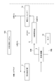
- FIG. 1 is a schematic diagram showing an embodiment of a hydrogen production system according to the present invention.
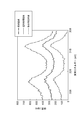
- FIG. 2 is a diagram showing an X-ray diffraction (XRD) pattern of a dehydrogenation catalyst according to an example of the present invention.
- XRD X-ray diffraction
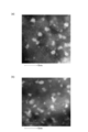
- FIG. 3 is an image of the dehydrogenation catalyst of Example 2 (dehydrogenation catalyst immediately after calcination) taken with a transmission electron microscope (TEM).
- B) in FIG. 3 is an image of the dehydrogenation catalyst of Example 2 (dehydrogenation catalyst immediately after the reduction treatment) taken by TEM.
- C in FIG. 3 is an image of the dehydrogenation catalyst of Example 2 (dehydrogenation catalyst after dehydrogenation reaction) taken by TEM.
- FIG. 4 is an image of the dehydrogenation catalyst of Comparative Example 2 (dehydrogenation catalyst immediately after calcination) taken with a transmission electron microscope (TEM).
- TEM transmission electron microscope
- B in FIG. 4 is an image of the dehydrogenation catalyst of Comparative Example 2 (dehydrogenation catalyst immediately after the reduction treatment) taken by TEM.
- C in FIG. 4 is an image of the dehydrogenation catalyst of Comparative Example 2 (dehydrogenation catalyst after dehydrogenation reaction) taken by TEM.
- A) in FIG. 5 is an image of the dehydrogenation catalyst of Example 2 (dehydrogenation catalyst immediately after the reduction treatment) taken with a high-angle scattering annular dark field-scanning transmission electron microscope (HAADF-STEM).
- HAADF-STEM high-angle scattering annular dark field-scanning transmission electron microscope
- FIG. 5 is an image of the dehydrogenation catalyst of Comparative Example 2 (dehydrogenation catalyst immediately after the reduction treatment) taken by HAADF-STEM.
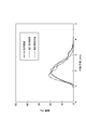
- FIG. 6 is a graph showing the particle size distribution of Pt particles carried on the dehydrogenation catalyst of Example 2 (particle size distribution of Pt particles immediately after calcination, immediately after the reduction treatment, and after the dehydrogenation reaction). It is.
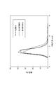
- FIG. 7 is a graph showing the particle size distribution of Pt particles carried on the dehydrogenation catalyst of Comparative Example 2 (particle size distribution of Pt particles immediately after firing, immediately after the reduction treatment, and after the dehydrogenation reaction). It is.
- FIG. 8 is a diagram showing an X-ray photoelectron spectroscopy (XPS) spectrum of the dehydrogenation catalyst of Example 2 (an XPS spectrum of the dehydrogenation catalyst immediately after calcination, immediately after the reduction treatment, and after the dehydrogenation reaction).
- FIG. 9 is a diagram showing XPS spectra of the dehydrogenation catalyst of Comparative Example 2 (XPS spectra of the dehydrogenation catalyst immediately after calcination, immediately after the reduction treatment, and after the dehydrogenation reaction).
- FIG. 10 is a schematic view showing the surface of a dehydrogenation catalyst according to an embodiment of the present invention.
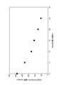
- FIG. 11 is a diagram showing the relationship between the content (mass%) of TiO 2 in the supports of Examples 1 to 3, 5, 6 and Comparative Example 2 and the methane concentration (molppm) in the product gas. .
- the dehydrogenation catalyst includes a carrier and a Group VIII element in the short periodic table carried on the carrier.
- Group VIII elements in the short periodic table correspond to Group 8 to 10 elements in the long periodic table (new periodic table) based on the provisions of IUPAC (International Pure Applied Chemistry Association).
- the support includes Al 2 O 3 (alumina) and TiO 2 (titania).
- the support may further contain SiO 2 (silica).
- the area of diffraction peaks derived from (101) plane of anatase TiO 2 is represented as A 1. That is, the X-ray diffraction pattern of the dehydrogenation catalyst has a peak derived from the (101) plane of the crystal lattice of anatase TiO 2 , and the area of the peak is A 1 .
- the area of the diffraction peak derived from the (400) plane of ⁇ -Al 2 O 3 is represented as A 2 .
- the X-ray diffraction pattern of the dehydrogenation catalyst has a peak derived from the (400) plane of the crystal lattice of ⁇ -Al 2 O 3 , and the area of the peak is A 2 .
- a 1 / A 2 is less than 0.17.
- a 1 / A 2 may be 0 or more and less than 0.17.
- Carrier may not include anatase TiO 2.
- a part of the carrier may be anatase TiO 2 .
- Part of the dehydrogenation catalyst support may be ⁇ -Al 2 O 3 .
- the dehydrogenation catalyst according to the present embodiment having the above characteristics has an excellent dehydrogenation activity and an excellent mechanical strength (crushing strength) as compared with a conventional dehydrogenation catalyst.
- hydrocarbon dehydrogenation (dehydrogenation reaction) using a dehydrogenation catalyst proceeds through the following route.
- the hydrocarbon comes into contact with the dehydrogenation catalyst in a reducing atmosphere.
- the group VIII element which is the active site, extracts at least a pair of hydrogen atoms from the hydrocarbon, thereby generating a hydrogen molecule and an unsaturated hydrocarbon.
- the activity of such a dehydrogenation catalyst that promotes dehydrogenation of hydrocarbons is called dehydrogenation activity.
- the dehydrogenation activity is evaluated based on the hydrocarbon conversion rate RC .
- a high conversion rate RC per unit volume of the dehydrogenation catalyst means that the dehydrogenation activity of the dehydrogenation catalyst is high.
- the conversion rate RC is defined by the following formula (1), for example.
- M 1 is the number of moles of hydrocarbons supplied to the reaction vessel in which the dehydrogenation catalyst is arranged.
- M 2 is the number of moles of unsaturated hydrocarbons contained in the product of the dehydrogenation reaction. In other words, M 2 is the number of moles of unsaturated hydrocarbons produced by hydrocarbon dehydrogenation.
- M 3 is the number of moles of the raw material (hydrocarbon not dehydrogenated) remaining after the dehydrogenation reaction.
- the mechanism by which the dehydrogenation catalyst according to this embodiment exhibits excellent dehydrogenation activity and excellent mechanical strength is estimated as follows.
- At least a part of TiO 2 is highly dispersed in the support in an amorphous state. It is estimated that at least a part of TiO 2 forms a composite oxide with Al 2 O 3 or the like.
- a complex oxide is formed, for example, from a mixed aqueous solution of a titanium mineral salt (for example, titanium sulfate) and an aluminum salt (for example, sodium aluminate).
- the above-described state of TiO 2 in the support is quantitatively defined by the numerical value A 1 / A 2 . That is, A 1 / A 2 being less than 0.17 suggests that TiO 2 is highly dispersed in the support in an amorphous state.
- a 1 / A 2 being less than 0.17 suggests that TiO 2 forms a composite oxide and is highly dispersed in the support.
- the support comprises SiO 2
- SiO 2 inhibits the grain growth of the alumina. Due to these factors, in this embodiment, the specific surface area of the carrier is increased and the dehydrogenation activity is improved as compared with the conventional dehydrogenation catalyst.
- most of TiO 2 is highly dispersed in the support in an amorphous state without being crystallized. That is, TiO 2 forms a complex oxide with Al 2 O 3 and the like and is highly dispersed in the carrier. Therefore, TiO 2 and Al 2 O 3 constituting the support are firmly bound to each other.
- the dehydrogenation catalyst according to the present embodiment is less likely to be crushed than the conventional dehydrogenation catalyst. That is, the dehydrogenation catalyst according to the present embodiment has excellent mechanical strength (crushing strength) compared to the conventional dehydrogenation catalyst. If case A 1 / A 2 is 0.17 or more, it is easy to present with TiO 2 is a crystalline state in the carrier, and TiO 2 crystalline, with the other components of the carrier (Al 2 O 3 or SiO 2) The physical bond strength of is weak. As a result, the carrier is easily crushed. That is, the mechanical strength (crushing strength) of the conventional dehydrogenation catalyst having A 1 / A 2 of 0.17 or more is inferior to that of the dehydrogenation catalyst according to this embodiment.
- a 1 / A 2 needs to be less than 0.17, and the carrier is Al 2 O. It is difficult to achieve both dehydrogenation activity and mechanical strength only by including 3 and TiO 2 .
- the mechanism relating to the dehydrogenation activity and mechanical strength of the dehydrogenation catalyst is not limited to the above mechanism.
- the conversion rate R ′ C per unit weight of the dehydrogenation catalyst according to this embodiment tends to be higher than that of the conventional dehydrogenation catalyst.
- the dehydrogenation catalyst according to this embodiment has a decatalytic activity equivalent to or higher than that of the conventional dehydrogenation catalyst even when the amount of the Group VIII element supported is smaller than that of the conventional dehydrogenation catalyst. Tend to have. Therefore, in the present embodiment, it is easy to reduce the amount of an expensive group VIII element (for example, platinum) supported without sacrificing the dehydrogenation activity.
- Conversion R 'C is calculated on the basis of the packed bulk density of the conversion R C and dehydrogenation catalyst for hydrocarbon (CBD).
- the conversion rate R ′ C is defined by the following formula (2), for example.
- Ls is the volume (unit: cc) of the dehydrogenation catalyst charged in the reaction vessel.
- CBD is the bulk density (unit: ml / g) of the dehydrogenation catalyst.
- a 0 is the area of the diffraction peak of the X-ray diffraction pattern of anatase TiO 2 itself, which is a standard sample different from the dehydrogenation catalyst.
- a 1 / A 0 is calculated from the area A 1 in the X-ray diffraction pattern of the dehydrogenation catalyst and the area A 0 in the X-ray diffraction pattern of the standard sample (anatase type TiO 2 ).
- the standard sample anatase type TiO 2
- the area of the measurement surface of the anatase TiO 2 (standard sample) used for the calculation of A 0 (measurement of the X-ray diffraction pattern) is the same as the measurement surface of the dehydrogenation catalyst used for the calculation of A 1 (measurement of the X-ray diffraction pattern). It may be equal to the area.
- a 1 / A 0 is less than 59/1000, the effect of the present invention tends to be more remarkable.
- a 1 / A 0 is less than 59/1000, it is presumed that almost all of TiO 2 in the catalyst is dispersed in the support in an amorphous state without being crystallized.
- the X-ray diffraction pattern of the dehydrogenation catalyst is measured using an X-ray diffractometer.
- Each of the diffraction peak areas A 1 and A 2 can be calculated by the following method. First, the obtained X-ray diffraction pattern is fitted by the method of least squares to perform baseline correction. Next, the height from the maximum peak value to the baseline (peak intensity W) is obtained. Next, a peak width (half width) at a half value (1/2 W) of the obtained peak intensity W is obtained. The product of the half width and the peak intensity W is the area of the diffraction peak.
- the diffraction angle 2 ⁇ of the diffraction peak derived from the (101) plane of anatase TiO 2 may be 25.5 °.
- the diffraction angle 2 ⁇ of the diffraction peak derived from the (400) plane of ⁇ -Al 2 O 3 may be 45.9 °.
- the X-ray diffraction pattern of the standard sample anatase TiO 2 itself and the area A 0 of the diffraction peak may be measured by the same method as in the case of the X-ray diffraction pattern of the dehydrogenation catalyst.
- the diffraction angle 2 ⁇ of diffraction peaks derived from (101) planes of the crystal lattice of the anatase type TiO 2 may be a 25.5 °.
- the position of the peak derived from the 4d 5/2 electrons of Pt is defined as E 1a .
- the binding energy of 4t 5/2 electrons of Pt supported on the carrier provided in the dehydrogenation catalyst immediately after calcination according to the present embodiment is defined as E 1a .
- the carrier provided in the dehydrogenation catalyst immediately after calcination according to the present embodiment may be paraphrased as a carrier containing Al 2 O 3 and TiO 2 .
- the 4d 5/2 electron means an electron whose energy level at Pt is 4d 5/2 .
- the position of the peak derived from the 4d 5/2 electrons of Pt in the XPS spectrum of the dehydrogenation catalyst immediately after calcination provided with the support containing Al 2 O 3 but not TiO 2 is defined as E 2a .
- the binding energy of 4d 5/2 electrons of Pt supported on a carrier composed only of Al 2 O 3 (or a carrier containing Al 2 O 3 but not TiO 2 ) is defined as E 2a .
- the value obtained by subtracting E 1a from E 2a (E 2a ⁇ E 1a ) may be 0.2 to 0.8 eV.
- the position of the peak derived from 4d 5/2 electrons of Pt in the XPS spectrum of the dehydrogenation catalyst immediately after the reduction treatment according to this embodiment is defined as E 1b .
- the binding energy of 4t 5/2 electrons of Pt supported on the carrier provided in the dehydrogenation catalyst immediately after the reduction treatment according to this embodiment is defined as E 1b .
- E 2b the position of the peak derived from the 4d 5/2 electrons of Pt in the XPS spectrum of the dehydrogenation catalyst immediately after the reduction treatment provided with the support containing Al 2 O 3 but not TiO 2 is defined as E 2b .
- the binding energy of 4t 5/2 electrons of Pt supported on a carrier composed only of Al 2 O 3 (or a carrier containing Al 2 O 3 but not TiO 2 ) is defined as E 2b .
- the value obtained by subtracting E 1b from E 2b (E 2b ⁇ E 1b ) may be 0.2 to 0.8 eV.
- the position of the peak derived from 4d 5/2 electrons of Pt in the XPS spectrum of the dehydrogenation catalyst after the dehydrogenation reaction according to this embodiment is defined as E 1c .
- the binding energy of 4t 5/2 electrons of Pt supported on the carrier provided in the dehydrogenation catalyst after the dehydrogenation reaction according to the present embodiment is defined as E 1c .
- the position of the peak derived from the 4d 5/2 electrons of Pt in the XPS spectrum of the dehydrogenation catalyst after the dehydrogenation reaction including a support containing Al 2 O 3 but not TiO 2 is defined as E 2c .
- the binding energy of 4t 5/2 electrons of Pt supported on a carrier composed only of Al 2 O 3 (or a carrier containing Al 2 O 3 but not TiO 2 ) is defined as E 2c .
- the value obtained by subtracting E 1c from E 2c (E 2c ⁇ E 1c ) is 0.2 to 1.1 eV, 0.2 to 1.0 eV, 0.2 to 0.8 eV, 0.3 to 1.1 eV, Alternatively, it may be 0.4 to 0.7 eV.
- the binding energy of 4d 5/2 electrons of Pt supported on the carrier provided in the dehydrogenation catalyst according to the present embodiment at any time immediately after calcination, immediately after the reduction treatment, and after the dehydrogenation reaction is Al.
- E 1a is smaller than E 2a as one of the factors that improve the dehydrogenation activity.
- E 1b and E 2b and the magnitude relationship between E 1c and E 2c are considered to be one of the factors that improve the dehydrogenation activity.
- the support may consist only of Al 2 O 3 and TiO 2 .
- the support may consist only of Al 2 O 3 , TiO 2 and SiO 2 .
- the carrier may contain a complex oxide.
- the composite oxide may be a composite oxide of Al and Ti, a composite oxide of Al and Si, a composite oxide of Ti and Si, or a composite oxide of Al, Ti, and Si.
- the support may be a composite oxide of Al and Ti.
- the carrier may be a composite oxide of Al, Ti, and Si.
- the carrier is a structure that substantially carries an active metal.
- the carrier may have the following functions. Helps the main catalyst to increase its catalytic activity or selectivity. Extend catalyst life. Increase the mechanical strength of the catalyst structure. Solidify the catalyst. Enables catalyst molding.
- the content of Ti in the carrier may be 3 to 40% by mass, 5 to 35% by mass or more and 5 to 30% by mass in terms of TiO 2 based on the total mass of the carrier. Good.
- the content of Ti is 3 to 40% by mass, the dehydrogenation activity tends to be further improved.
- carbon deposition is further suppressed, and high dehydrogenation activity tends to be maintained for a longer period of time.
- the mechanical strength of the catalyst tends to be further improved.
- the dehydrogenation catalyst which concerns on this embodiment can suppress the demethylation accompanying the dehydrogenation of the cyclic saturated hydrocarbon which has a methyl group compared with the conventional dehydrogenation catalyst. “Demethylation” is elimination of a methyl group from a cyclic saturated hydrocarbon and formation of methane.
- the cyclic saturated hydrocarbon having a methyl group may be, for example, at least one selected from the group consisting of methylcyclohexane, dimethylcyclohexane, 1-methyldecalin, and 2-methyldecalin. These compounds are called organic hydrides.
- the cyclic saturated hydrocarbon having a methyl group is preferably at least one selected from the group consisting of methylcyclohexane and dimethylcyclohexane.
- FIG. 10 is a schematic view showing the surface of the dehydrogenation catalyst according to the present embodiment.
- Pt supported on the surface of the carrier 200 has dehydrogenation activity and demethylation activity. As shown in FIG. 10, when methylcyclohexane comes into contact with the dehydrogenation catalyst, Pt, which is the active site, pulls out a hydrogen atom from methylcyclohexane to generate hydrogen molecules and toluene. Since electrons are donated from Ti in the carrier 200 to Pt, the electron-donated Pt and the ⁇ electrons of toluene tend to repel each other. In addition, since the carrier 200 contains Ti having high affinity with toluene, toluene has an affinity for the carrier 200 itself.
- the content of Al in the support may be 50 to 96% by mass or 67 to 92% by mass in terms of Al 2 O 3 based on the total mass of the support.
- the Si content in the support may be 0 to 10% by mass, 1 to 10% by mass, or 2 to 4% by mass in terms of SiO 2 based on the total mass of the support.
- the shape of the carrier is not particularly limited.
- the carrier may be in the form of pellets, a plate, or a honeycomb.
- the Group VIII element may be supported on the surface of the carrier.
- the surface is a portion where an active metal such as a Group VIII element is supported, and is a portion where a catalytic reaction proceeds. At least a part of the Group VIII element may be present on the surface of TiO 2 contained in the support.
- the Group VIII element may be supported on the carrier as a large number of atoms, clusters or fine particles.
- the particle size of the Group VIII element fine particles supported on the carrier is not particularly limited, but may be, for example, 10 nm or less, and may be, for example, 1.6 to 2.1 nm.
- the elements of Group VIII of the short periodic table are Fe (iron), Ru (ruthenium), Os (osmium), Co (cobalt), Rh (rhodium), Ir (iridium). ), Ni (nickel), Pd (palladium), and Pt (platinum).
- the dehydrogenation catalyst may include only one kind of Group VIII element, or may include two or more kinds of Group VIII elements. When the Group VIII element is Pt, the dehydrogenation activity tends to be more remarkable.
- the amount of the Group VIII element supported on the dehydrogenation catalyst is not particularly limited, but may be 0.1 to 1% by mass based on the total mass of the dehydrogenation catalyst. There exists a tendency for dehydrogenation activity to improve more because the load of a Group VIII element is more than said lower limit. When the loading amount of the Group VIII element exceeds the above upper limit value, the degree of improvement in the catalyst activity accompanying the increase in the loading amount of the Group VIII element becomes moderate. Further, when Pt is used as the Group VIII element, the price of Pt is very high, so the amount of Pt supported is limited for practical use of the dehydrogenation catalyst.
- the specific surface area (SA) of the dehydrogenation catalyst may be, for example, 150 m 2 / g or more and 400 m 2 / g or less, or 318 m 2 / g or more and 350 m 2 / g or less. What is necessary is just to measure the specific surface area of a support
- the total pore volume (PV 0 ) of the dehydrogenation catalyst may be from 0.30 ml / g to 0.90 ml / g, from 0.50 ml / g to 0.80 ml / g, It may be from .56 ml / g to 0.72 ml / g.
- the total pore volume (PV 0 ) is the total volume of pores having a pore diameter of 4.1 nm (41 cm) or more.
- 4.1 nm (41 ⁇ ) is a quantitative limit in measurement.
- the total pore volume of the dehydrogenation catalyst may be measured by a mercury intrusion method (mercury contact angle: 135 degrees, surface tension: 480 dyn / cm).
- the average pore diameter (PD) of the dehydrogenation catalyst may be 6-15 nm (60-150 mm). When the average pore diameter (PD) is 6 nm or more, the dehydrogenation activity tends to be improved more easily. When the average pore diameter (PD) is 15 nm or less, the specific surface area (SA) tends to be increased, and the dehydrogenation activity tends to be more improved. Moreover, it is difficult to produce a dehydrogenation catalyst having an average pore diameter (PD) exceeding 15 nm.
- the average pore diameter (PD) represents a pore diameter corresponding to 50% of the total pore volume (PV 0 ).
- the specific surface area (SA), total pore volume (PV 0 ) and average pore diameter (PD) of the dehydrogenation catalyst are the specific surface area (SA), total pore volume (PV 0 ) and the support of the dehydrogenation catalyst. It may be on the same order as the average pore diameter (PD).
- the packing bulk density (CBD) of the dehydrogenation catalyst may be 0.55 g / ml or more and 0.80 g / ml or less, may be 0.60 g / ml or more and 0.75 g / ml or less, and may be 0.64 g / ml. It may be not less than ml and not more than 0.75 g / ml.
- the volume of pores having a mean pore diameter (PD) pore diameter of ⁇ 30% is PV P, when the total pore volume is PV 0, there is (PV P / PV 0) 70% or more Good.
- PV P mean pore diameter
- PV P / PV 0 70% or more Good.
- the pore distribution of the dehydrogenation catalyst is sharp. If PV P / PV 0 is 70%, the pore distribution of the catalyst is hardly becomes broad, there is tendency dehydrogenation activity is further improved.
- the support may contain components other than Al 2 O 3 and TiO 2 .
- other components other than the Group VIII element may be supported on the carrier as long as the effects of the present invention are not impaired.
- the dehydrogenation catalyst according to the present embodiment includes, for example, a step of preparing a slurry that is a raw material for a carrier (first step) and a step of producing a carrier using the obtained slurry (second step) as follows. And a step of supporting the group VIII element on the carrier (third step).
- a mixed aqueous solution of titanium mineral acid and acidic aluminum salt (hereinafter also referred to as “aqueous solution A”) that is an acidic aqueous solution and a basic aluminum salt aqueous solution that is an alkaline aqueous solution are mixed with silicic acid.
- aqueous solution A a mixed aqueous solution of titanium mineral acid and acidic aluminum salt
- a basic aluminum salt aqueous solution that is an alkaline aqueous solution
- the titanium mineral salt may be at least one selected from the group consisting of titanium tetrachloride, titanium trichloride, titanium sulfate, and titanium nitrate. Among these, titanium sulfate is preferably used because it is inexpensive.
- the acidic aluminum salt may be at least one selected from the group consisting of aluminum sulfate, aluminum chloride, and aluminum nitrate.
- the basic aluminum salt may be at least one selected from the group consisting of sodium aluminate and potassium aluminate.
- the aqueous solution A may be added to an aqueous solution (hereinafter also referred to as “aqueous solution B”) in which a silicate ion is contained in a basic aluminum salt aqueous solution.
- aqueous solution B aqueous solution
- the ion source (silicate ion source) of the silicate ion may be basic or neutral.
- the silicate ion source may be a silicate compound that generates silicate ions in water.
- the basic silicate ion source may be, for example, sodium silicate.
- a basic aluminum salt aqueous solution may be added to the aqueous solution containing the silicate ions in the aqueous solution A.
- the silicate ion source may be acidic or neutral.
- the acidic silicate ion source may be, for example, silicic acid.
- a hydrate slurry containing Al 2 O 3 , TiO 2 and SiO 2 can be obtained by the following procedure.
- a predetermined amount of a basic silicate ion source is added to a basic aqueous aluminum salt solution to obtain an aqueous solution B.
- the obtained aqueous solution B is put into a tank equipped with a stirrer, and is usually heated to 40 to 90 ° C., preferably 50 to 70 ° C. and held.
- the aqueous solution A heated to ⁇ 5 ° C., preferably ⁇ 2 ° C., more preferably ⁇ 1 ° C. of the aqueous solution B is added to the aqueous solution B.
- the aqueous solution A is added so that the pH of the aqueous solution after the addition is 6.5 to 9.5, preferably 6.5 to 8.5, more preferably 6.5 to 7.5.
- the addition of the aqueous solution A is usually carried out continuously over 5 to 20 minutes, preferably over 7 to 15 minutes.
- a hydrate slurry containing Al 2 O 3 , TiO 2 and SiO 2 is obtained as a precipitate.
- the addition time becomes long, in addition to pseudoboehmite, undesired crystals such as bayerite and gibbsite may be generated.
- the addition time is desirably 15 minutes or less, and more desirably 13 minutes or less.
- the contents of Al 2 O 3 , TiO 2 , and SiO 2 in the support are the concentration of titanium ions and aluminum ions in the aqueous solution A, the concentration of aluminum ions in the basic aluminum salt aqueous solution, and the silicate ions contained in the aqueous solution A or B. It can be adjusted by adjusting the amount.
- a slurry is produced by adding an acidic aqueous solution to a basic aqueous solution and neutralizing it.
- a slurry may be produced by adding a basic aqueous solution to an acidic aqueous solution and neutralizing it. When neutralization is performed, it is difficult to adjust the Ti content to 50 mol% or more based on the total mass of the carrier.
- a support containing Al 2 O 3 , TiO 2 and SiO 2 is obtained from the slurry obtained in the first step. Specifically, first, the slurry obtained in the first step is aged as desired, and then the obtained slurry is washed to remove by-product salts. Next, the washed slurry is further heated and aged as required to form a desired shape. For example, after the slurry is heated and kneaded to obtain a moldable kneaded product, the obtained kneaded material may be molded by extrusion molding or the like. Next, the obtained molded product is usually dried at 70 to 150 ° C., preferably 90 to 130 ° C.
- the molded product after drying is further calcined at 400 to 800 ° C., preferably 450 to 600 ° C., for 0.5 to 10 hours, preferably 2 to 5 hours.
- a support containing Al 2 O 3 , TiO 2 and SiO 2 can be obtained.
- a solution (for example, an aqueous solution) of the Group VIII element is supported on the carrier obtained in the second step.
- the supporting method may be an incipient wetness method, a pore filling method, an adsorption method, a dipping method, an evaporation to dryness method, a spray method, an ion exchange method, a liquid phase reduction method, or the like.
- the Group VIII element is attached to the surface of the carrier.
- the amount of the Group VIII element supported in the dehydrogenation catalyst can be adjusted by adjusting the concentration of the Group VIII element in the Group VIII element solution or the amount of the Group VIII element solution used.
- the group VIII element solution can be prepared, for example, by dissolving a group VIII element compound in a solvent.
- the compound of the Group VIII element is not particularly limited, but is required to be soluble in a liquid solvent.
- the group VIII element compound may be nitrate, sulfate, carbonate, acetate, phosphate, oxalate, borate, chloride, alkoxide, acetylacetonate, and the like.
- the Group VIII element compound is a Pt compound.
- Pt compounds are tetrachloroplatinic acid, potassium tetrachloroplatinate, ammonium tetrachloroplatinate, sodium tetrachloroplatinate, bis (acetylacetonato) platinum, diamminedichloroplatinum, dinitrodiammineplatinum, tetraammineplatinum dichloride, tetraammineplatinum water Acid salt, tetraammine platinum nitrate, tetraammine platinum acetate, tetraammine platinum carbonate, tetraammine platinum phosphate, hexaammine platinum tetrachloride, hexaammine platinum hydrochloride, hexaammine platinum hydrochloride, bis (ethanolammonium) hexahydroxo At least one selected from the group consisting of platinum (IV), sodium hexa
- the carrier carrying the compound of the group VIII element is calcined and the compound of the group VIII element is decomposed, whereby the group VIII element is carried on the carrier, and the dehydrogenation catalyst according to this embodiment is completed.
- the firing temperature may be any temperature at which decomposition of the Group VIII element compound proceeds, and may be, for example, about 200 to 500 ° C.
- the hydrogen production system 100 is, for example, a hydrogen station for supplying hydrogen gas as fuel to a fuel cell vehicle.
- the hydrogen production system 100 includes at least a dehydrogenation reactor 2, a gas-liquid separator 4, a hydrogen purification device 6, and a tank 16.
- the manufacturing system 100 may further include a high-pressure compressor 14.
- the dehydrogenation reactor 2 includes the dehydrogenation catalyst according to the present embodiment, and generates hydrogen and an organic compound (such as an unsaturated hydrocarbon) by dehydrogenation of the hydrocarbon using the dehydrogenation catalyst. That is, the method for producing hydrogen according to the present embodiment includes a step (dehydrogenation step) of generating hydrogen and an organic compound by dehydrogenation of hydrocarbons using the dehydrogenation catalyst according to the present embodiment.
- the hydrocarbon may be, for example, a naphthenic hydrocarbon (cyclic hydrocarbon).
- the naphthenic hydrocarbon (cyclic hydrocarbon) may be, for example, at least one selected from the group consisting of cyclohexane, methylcyclohexane, dimethylcyclohexane, decalin, 1-methyldecalin, 2-methyldecalin and 2-ethyldecalin. . These compounds are called organic hydrides.
- hydrocarbons are supplied into the dehydrogenation reactor 2.
- the dehydrogenation catalyst according to the present embodiment is installed.
- the inside of the dehydrogenation reactor 2 is a reducing atmosphere.
- a dehydrogenation reaction takes place, and at least a pair of hydrogen atoms are extracted from the hydrocarbon.
- a naphthenic hydrocarbon is used as the hydrocarbon, a hydrogen molecule and an organic compound (unsaturated hydrocarbon) such as an aromatic hydrocarbon are generated.
- the dehydrogenation reaction is a gas phase reaction.
- hydrogen may be supplied into the dehydrogenation reactor 2 together with the hydrocarbon. This tends to maintain the dehydrogenation activity for a longer period.
- the conditions for the dehydrogenation reaction are not particularly limited.
- the reaction temperature may be 250-420 ° C.
- the temperature of the central portion of the catalyst layer in the dehydrogenation reactor 2 may be adjusted to the above range.
- the liquid hourly space velocity (LHSV) may be between 0.2 and 4.0 h ⁇ 1 .
- the hydrogen partial pressure may be 0.1 to 1.0 MPa.
- the molar number n H of hydrogen supplied to the dehydrogenation reactor 2 the ratio n H / n C of the moles n C hydrocarbons supplied to the dehydrogenation reactor 2 0.05-1. It may be zero.
- the product (hydrogen molecule and organic compound) of the dehydrogenation reaction is supplied from the dehydrogenation reactor 2 into the gas-liquid separator 4.
- the temperature in the gas-liquid separator 4 is not lower than the melting point of the organic compound and lower than the boiling point of the organic compound. Therefore, the hydrogen molecules in the gas-liquid separator 4 are gases, and the organic compounds in the gas-liquid separator 4 are liquids. That is, in the gas-liquid separator 4, the product of the dehydrogenation reaction is separated into hydrogen gas (gas phase, gas layer) and organic compound liquid (liquid phase, liquid layer).
- the gas phase (hydrogen-containing gas) in the gas-liquid separator 4 is supplied to the hydrogen purifier 6.
- the liquid phase (organic compound liquid) in the gas-liquid separator 4 is supplied to the tank 16.
- vapor of an organic compound may be mixed in the gas phase.
- the partial pressure of the organic compound in the gas phase is at most about the saturated vapor pressure of the organic compound.
- organic hydride that has not been dehydrogenated may remain in the liquid phase.
- the hydrogen-containing gas supplied from the gas-liquid separator 4 to the hydrogen purification device 6 is purified by the hydrogen purification device 6.
- the hydrogen purifier 6 may include, for example, a separation membrane that selectively allows only hydrogen gas among hydrogen gas and organic compounds to permeate.
- the separation membrane is, for example, a metal membrane (such as a PbAg-based membrane, a PdCu-based membrane, or an Nb-based membrane), an inorganic membrane (such as a silica membrane, a zeolite membrane, or a carbon membrane), or a polymer membrane (a fluororesin membrane or polyimide).
- a membrane A membrane).
- the hydrogen gas permeates through the separation membrane, thereby increasing the purity of the hydrogen gas.
- the organic compound is separated from the hydrogen-containing gas, and high-purity hydrogen gas is purified.
- the purified high-purity hydrogen gas may be used as fuel for the fuel cell without passing through the high-pressure compressor 14, or may be used as fuel for the fuel cell after being compressed by the high-pressure compressor 14.
- hydrogen gas that has not permeated the carbon membrane may be recovered together with the organic hydride and supplied as an off-gas into the dehydrogenation reactor 2. Alternatively, the organic compound that has not permeated the carbon film may be collected into the tank 16.
- the hydrogen purification apparatus 6 is not limited to an apparatus provided with a separation membrane.
- the hydrogen purifier 6 is selected from the group consisting of, for example, a pressure swing adsorption (PSA) method, a thermal swing adsorption (TSA) method (temperature swing adsorption method), a temperature pressure swing adsorption (TPSA) method, and a cryogenic separation method.
- An apparatus that performs at least one method may be used. These apparatuses may be used to purify the hydrogen-containing gas, supply the off-gas generated along with the purification into the dehydrogenation reactor 2, and supply the organic compound separated from the hydrogen-containing gas to the tank 16.
- a part of the purified hydrogen gas may be supplied to the dehydrogenation reactor 2 together with the organic hydride. Thereby, the dehydrogenation activity of the dehydrogenation catalyst in the dehydrogenation reactor 2 is easily maintained.
- Example 1 A basic silicate ion source was added to the basic aluminum salt aqueous solution to obtain an aqueous solution B.
- the aqueous solution B was put into a tank with a stirrer and heated to 60 ° C. and held.
- a heated mixed aqueous solution (aqueous solution A) of a titanium mineral acid salt and an acidic aluminum salt was continuously added over 10 minutes.
- the aqueous solution A was added so that the pH of the aqueous solution after the addition was 7.2.
- a hydrate slurry containing Al 2 O 3 , TiO 2 and SiO 2 was obtained as a precipitate.
- Sodium silicate was used as the silicate ion source.
- Sodium aluminate was used as the basic aluminum salt.
- Titanium sulfate was used as the titanium mineral salt.
- Aluminum sulfate was used as the acidic aluminum salt.
- Step (2) Next, the slurry obtained above was washed. Next, the washed slurry was molded to obtain a molded product. After drying the obtained molding, the dried molding was fired at 550 ° C. for 3 hours to obtain a carrier containing Al 2 O 3 , TiO 2 and SiO 2 .
- the contents of Al, Ti and Si in the support are shown in Table 1 below.
- content of Al, Ti, and Si is content in conversion of an oxide on the basis of the total mass of a support
- the X-ray diffraction pattern of the obtained carrier was measured using an X-ray diffractometer. RINT2100 manufactured by Rigaku Corporation was used as the X-ray diffractometer.
- the X-ray diffraction pattern of the carrier of Example 1 is shown in FIG. In the measured X-ray diffraction pattern, a diffraction peak at a diffraction angle 2 ⁇ of 25.5 ° did not appear. That is, in the X-ray diffraction pattern of the carrier of Example 1, no diffraction peak derived from the (101) plane of anatase TiO 2 appeared.
- the area A 1 of the diffraction peak derived from the (101) plane of TiO 2 was almost zero.
- the half width of the diffraction peak derived from the (400) plane of ⁇ -Al 2 O 3 was determined.
- the area A 2 of the diffraction peak was determined from the product of the half width and the peak intensity W 2 .
- the X-ray diffraction pattern of anatase TiO 2 (standard sample different from the dehydrogenation catalyst) was measured in the same manner as the support.
- the area A 0 of the diffraction peak derived from the (101) plane of anatase TiO 2 was determined. From the above measurement results, A 1 / A 2 and A 1 / A 0 of the carrier of Example 1 were calculated. The calculation results are shown in Table 1 below.
- the diffraction peak shown around 69.0 ° is a diffraction peak derived from the (440) plane of ⁇ -Al 2 O 3 .
- the area of the measurement surface of anatase TiO 2 (standard sample) was equal to the area of the measurement surface of the sample of the carrier of Example 1 used for measurement of the X-ray diffraction pattern used for measurement of the X-ray diffraction pattern.
- Step (3) Next, the Pt compound solution was supported on the carrier of Example 1 by the pore filling method. Bis (ethanolammonium) hexahydroxoplatinum (IV) was used as the Pt compound. Thereby, the dehydrogenation catalyst of Example 1 was obtained.
- the amount (content) of Pt supported in the dehydrogenation catalyst, and the properties of the dehydrogenation catalyst (specific surface area (SA), total pore volume (PV 0 ), average pore diameter (PD), crushing strength (Cr.str) .), Packed bulk density (CBD), Pt surface area (Am), Pt dispersity (Dm) and Pt particle diameter) are shown in Table 1 below.
- the supported amount of Pt is a supported amount (unit: mass%) based on the total mass of the dehydrogenation catalyst.
- SA Specific surface area
- PV 0 The total pore volume
- CBD filling bulk density
- Pt surface area (Am) and Pt dispersity (Dm) were measured using a chemical adsorption method.
- CO carbon monoxide
- the adsorption amount (unit: cm 3 / g) was calculated.
- the amount of Pt existing on the catalyst surface per unit mass of Pt and acting as an active site was calculated.
- Pt dispersion degree (Dm) was calculated based on the CO adsorption amount.
- Pt surface area (Am) is defined by following formula (3).
- the Pt dispersity (Dm) is defined by the following formula (4).
- Am V chem ⁇ SF / 22414 ⁇ N A ⁇ ⁇ m ⁇ 10 -18 (3)
- Dm V chem x (SF / 22414) x Mw x (1 / c) x 100 (4)
- Am is a Pt surface area (unit: m 2 / g).
- V chem is the amount of CO adsorption (unit: cm 3 ) in the dehydrogenation catalyst.
- SF is the stoichiometric ratio of CO adsorption and is 1.
- N A is Avogadro's number.
- ⁇ m is a cross-sectional area (unit: nm 2 / atom) of one Pt atom.
- Dm is the Pt dispersity (unit:%).
- Mw is the atomic weight of Pt (unit: g / mol).
- c is the mass (unit: g) of the supported Pt.
- the product oil was analyzed with a gas chromatograph-hydrogen ionization detector (GC-FID), and it was 270 ° C. from the ratio of the GC area (peak area) of MCH contained in the product oil to the GC area of toluene contained in the liquid.
- the conversion ratio r C of MCH was calculated (see the following definition formula (5)). Further, based on the conversion rate r C and the bulk density (CBD) of the dehydrogenation catalyst, the conversion rate r ′ C of MCH per unit weight of the catalyst at 270 ° C. was calculated (see the following definition formula (6)). .
- the conversion rate r C and the conversion rate r ′ C at 270 ° C. are shown in Table 2 below.
- Conversion rate r C (unit:%) (m 2 / m 1 ) ⁇ 100 (5)
- Conversion r ′ C (unit:% / g-cat.) R C / (Ls ⁇ CBD) (6)
- m 1 is the number of moles of methylcyclohexane supplied to the reaction vessel in which the dehydrogenation catalyst is arranged.
- m 2 is the number of moles of toluene contained in the product of the dehydrogenation reaction.
- Ls is the amount (unit: cc) of the dehydrogenation catalyst charged in the reaction vessel.
- CBD is the bulk density (unit: ml / g) of the dehydrogenation catalyst.
- Example 2 In order to obtain a carrier having the composition shown in Table 1 below, in step (1), the concentrations of silicate ions and aluminum ions in the aqueous solution B, and the concentrations of titanium ions and aluminum ions in the aqueous solution A were adjusted. Except for this point, the carrier of Example 2 was obtained in the same manner as Example 1. Further, in the same manner as in Example 1, the support was subjected to X-ray diffraction analysis. The obtained XRD pattern is shown in FIG. Further, A 1 / A 2 and A 1 / A 0 of Example 2 were calculated in the same manner as Example 1. The results are shown in Table 1 below.
- Example 2 A dehydrogenation catalyst of Example 2 was obtained in the same manner as Example 1 except for this point.
- the properties of the dehydrogenation catalyst of Example 2 are shown in Table 1 below.
- the dehydrogenation activity of Example 2 was evaluated in the same manner as Example 1. The evaluation results are shown in Table 2 below.
- Example 3 In order to obtain a carrier having the composition shown in Table 1 below, in step (1), the concentrations of silicate ions and aluminum ions in the aqueous solution B, and the concentrations of titanium ions and aluminum ions in the aqueous solution A were adjusted. Except for this point, the carrier of Example 3 was obtained in the same manner as Example 1. Further, in the same manner as in Example 1, the support was subjected to X-ray diffraction analysis. The obtained XRD pattern is shown in FIG. Further, A 1 / A 2 and A 1 / A 0 of Example 3 were calculated in the same manner as Example 1. The results are shown in Table 1 below.
- Example 3 the concentration of Pt ions in the Pt compound solution was adjusted. Except for this point, the dehydrogenation catalyst of Example 3 was obtained in the same manner as Example 1. The properties of the dehydrogenation catalyst of Example 3 are shown in Table 1 below. Further, the dehydrogenation activity of Example 3 was evaluated in the same manner as Example 1. The evaluation results are shown in Table 2 below.
- Example 4 In order to obtain a carrier having the composition shown in Table 1 below, in step (1), the concentrations of silicate ions and aluminum ions in the aqueous solution B, and the concentrations of titanium ions and aluminum ions in the aqueous solution A were adjusted. Except for this point, the carrier of Example 4 was obtained in the same manner as Example 1. Further, in the same manner as in Example 1, the support was subjected to X-ray diffraction analysis. The obtained XRD pattern is shown in FIG. Further, in the same manner as in Example 1, A 1 / A 2 and A 1 / A 0 of Example 4 were calculated. The results are shown in Table 1 below.
- Example 4 was obtained in the same manner as Example 1 except for this point.
- the properties of the dehydrogenation catalyst of Example 4 are shown in Table 1 below.
- the dehydrogenation activity of Example 4 was evaluated in the same manner as Example 1. The evaluation results are shown in Table 2 below.
- Comparative Example 1 In order to obtain a carrier having the composition shown in Table 1 below, in step (1), the concentrations of silicate ions and aluminum ions in the aqueous solution B, and the concentrations of titanium ions and aluminum ions in the aqueous solution A were adjusted. Except for this point, a support of Comparative Example 1 was obtained in the same manner as Example 1.
- the X-ray diffraction pattern of the carrier of Comparative Example 1 was measured.
- the X-ray diffraction pattern of the carrier of Comparative Example 1 is shown in FIG.
- the measured X-ray diffraction pattern was fitted by the least square method, and the baseline was corrected.
- the half width of the diffraction peak (“P 1 ” in FIG. 2) derived from the (101) plane of anatase TiO 2 at a diffraction angle 2 ⁇ of 25.5 ° was obtained.
- the area A 1 of the diffraction peak was determined from the product of this half width and the peak intensity W 1 of P 1 (the height from the maximum peak value to the baseline).
- the half width of the diffraction peak (“P 2 ” in FIG. 2) derived from the (400) plane of ⁇ -Al 2 O 3 at a diffraction angle 2 ⁇ of 45.9 ° was determined.
- the area A 2 of the diffraction peak was determined from the product of the half width and the peak intensity W 2 of P 2 . From the above measurement results, A 1 / A 2 and A 1 / A 0 of the carrier of Comparative Example 1 were calculated. The calculation results are shown in Table 1 below.
- Comparative Example 2 In order to obtain a carrier having the composition shown in Table 1 below, an aqueous solution of acidic aluminum salt was used in place of the aqueous solution A in step (1). Moreover, in order to obtain the support
- the concentration of Pt ions in the Pt compound solution was adjusted. Except for this point, a dehydrogenation catalyst of Comparative Example 2 was obtained in the same manner as in Example 1.
- the properties of the dehydrogenation catalyst of Comparative Example 2 are shown in Table 1 below.
- the average pore diameter (PD) of the comparative example 2 measured by the gas adsorption method was 140 mm.
- the dehydrogenation activity of Comparative Example 2 was evaluated.
- the evaluation results are shown in Table 2 below.
- the carbon deposition amount of Comparative Example 2 was evaluated. The amount of carbon deposition was 0.45% by mass based on the total mass of the dehydrogenation catalyst before the evaluation of the carbon deposition amount.
- dehydrogenation catalysts of Examples 2A, 2B, 2C, and 2D having different Pt loadings were prepared.
- Example 2A In the same manner as in Example 2, a support containing Al 2 O 3 , TiO 2 and SiO 2 was obtained. Subsequently, in order to control the supported amount of Pt in the dehydrogenation catalyst to the value shown in Table 3 below, in the step (3), the concentration of Pt ions in the solution of the Pt compound was adjusted. Except for this point, the dehydrogenation catalyst of Example 2A was obtained in the same manner as Example 2. The properties of the dehydrogenation catalyst of Example 2A are shown in Table 3 below. In the same manner as in Example 2, the dehydrogenation activity of Example 2A was evaluated, and the conversion ratio r C at 270 ° C., 280 ° C., 290 ° C., 300 ° C. and 310 ° C. was calculated. The results are shown in Table 3 below.
- Example 2B In the same manner as in Example 2, a support containing Al 2 O 3 , TiO 2 and SiO 2 was obtained. Subsequently, in order to control the supported amount of Pt in the dehydrogenation catalyst to the value shown in Table 3 below, in the step (3), the concentration of Pt ions in the solution of the Pt compound was adjusted. Except for this point, the dehydrogenation catalyst of Example 2B was obtained in the same manner as Example 2. The properties of the dehydrogenation catalyst of Example 2B are shown in Table 3 below. In the same manner as in Example 2, the dehydrogenation activity of Example 2B was evaluated, and the conversion ratio r C at 270 ° C., 280 ° C., 290 ° C., 300 ° C. and 310 ° C. was calculated. The results are shown in Table 3 below.
- Example 2C In the same manner as in Example 2, a support containing Al 2 O 3 , TiO 2 and SiO 2 was obtained. Subsequently, in order to control the supported amount of Pt in the dehydrogenation catalyst to the value shown in Table 3 below, in the step (3), the concentration of Pt ions in the solution of the Pt compound was adjusted. Except for this point, the dehydrogenation catalyst of Example 2C was obtained in the same manner as Example 2. The properties of the dehydrogenation catalyst of Example 2C are shown in Table 3 below. In the same manner as in Example 2, the dehydrogenation activity of Example 2C was evaluated, and the conversion ratio r C at 270 ° C., 280 ° C., 290 ° C., 300 ° C. and 310 ° C. was calculated. The results are shown in Table 3 below.
- Example 2D In the same manner as in Example 2, a support containing Al 2 O 3 , TiO 2 and SiO 2 was obtained. Subsequently, in order to control the supported amount of Pt in the dehydrogenation catalyst to the value shown in Table 3 below, in the step (3), the concentration of Pt ions in the solution of the Pt compound was adjusted. Except for this point, the dehydrogenation catalyst of Example 2D was obtained in the same manner as Example 2. The properties of the dehydrogenation catalyst of Example 2D are shown in Table 3 below. Further, in the same manner as in Example 2, the dehydrogenation activity of Example 2D was evaluated, and the conversion ratio r C at 270 ° C., 280 ° C., 290 ° C., 300 ° C. and 310 ° C. was calculated. The results are shown in Table 3 below.
- Table 3 shows the relationship between the amount of Pt supported in the dehydrogenation catalyst and the dehydrogenation activity.
- the unused dehydrogenation catalyst of Example 2 was photographed with a transmission electron microscope (TEM) to obtain a TEM image.
- the unused dehydrogenation catalyst means a dehydrogenation catalyst immediately after calcination (immediately after the step (3)) and before performing the following reduction treatment.
- the obtained TEM image was processed with image analysis software, and the particle diameter of each Pt particle supported on the dehydrogenation catalyst was measured. From the measured particle size of each Pt particle (a plurality of Pt particles), the particle size distribution and average particle size of the Pt particles were determined. In the same manner as in Example 2, the particle size distribution and average particle size of Pt particles supported on the dehydrogenation catalyst of Comparative Example 2 immediately after calcination were obtained.
- the dehydrogenation catalyst of Example 2 immediately after calcination was heated at 250 ° C. for 0.5 hours in a reducing atmosphere.
- this process is referred to as a reduction process.
- the particle size distribution and average particle size of the Pt particles carried on the dehydrogenation catalyst of Example 2 immediately after the reduction treatment were determined by the same method as described above.
- the particle size distribution and average particle size of the Pt particles supported on the dehydrogenation catalyst of Comparative Example 2 immediately after the reduction treatment were obtained.
- the following dehydrogenation reaction was performed using the dehydrogenation catalyst of Example 2 immediately after calcination.
- 4 cc of dehydrogenation catalyst was charged into a fixed bed flow type reactor.
- the outlet temperature at the center of the catalyst layer is maintained at 340 ° C.
- the dehydrogenation reaction of was continued.
- the reaction pressure was 0.19 MPaG.
- the liquid space velocity (LHSV) of MCH fed into the reactor was maintained at 1.5 h ⁇ 1 .
- the particle size distribution and average particle size of the Pt particles supported on the dehydrogenation catalyst of Example 2 after the above dehydrogenation reaction were determined by the same method as described above. In the same manner as in Example 2, the particle size distribution and average particle size of the Pt particles supported on the dehydrogenation catalyst of Comparative Example 2 after the dehydrogenation reaction were obtained.
- FIG. 3 shows a TEM image of the dehydrogenation catalyst of Example 2 immediately after calcination.
- a TEM image of the dehydrogenation catalyst of Example 2 immediately after the reduction treatment is shown in (b) of FIG.
- a TEM image of the dehydrogenation catalyst of Example 2 after the dehydrogenation reaction is shown in (c) of FIG.
- a TEM image of the dehydrogenation catalyst of Comparative Example 2 immediately after calcination is shown in FIG.
- a TEM image of the dehydrogenation catalyst of Comparative Example 2 immediately after the reduction treatment is shown in (b) of FIG.
- a TEM image of the dehydrogenation catalyst of Comparative Example 2 after the dehydrogenation reaction is shown in (c) of FIG.
- white dots indicate Pt particles. It was confirmed by surface analysis using EDX that white dots in the TEM image indicate Pt particles. That is, it was confirmed that the white dots in the HAADF-STEM image almost overlap with the Pt distribution obtained by the surface analysis by EDX. Further, it was confirmed by surface analysis by EDX that Ti was uniformly dispersed in the dehydrogenation catalyst of Example 2 immediately after the reduction treatment. An image of the dehydrogenation catalyst of Example 2 taken immediately after the reduction treatment, taken by HAADF-STEM, is shown in (a) of FIG. An image of the dehydrogenation catalyst of Comparative Example 2 immediately after the reduction treatment, taken by HAADF-STEM, is shown in (b) of FIG. FIG.
- FIG. 6 shows the particle size distribution of Pt particles supported on the dehydrogenation catalyst of Example 2 (particle size distribution of Pt particles immediately after calcination, immediately after the reduction treatment, and after the dehydrogenation reaction).
- FIG. 7 shows the particle size distribution of Pt particles supported on the dehydrogenation catalyst of Comparative Example 2 (immediately after calcination, immediately after the reduction treatment, and after the dehydrogenation reaction).
- the average particle diameter of the Pt particles carried on the dehydrogenation catalyst of Example 2 immediately after calcination was 2.0 nm.
- the standard deviation of the average particle diameter of the Pt particles carried on the dehydrogenation catalyst of Example 2 immediately after calcination was 0.47 nm.
- the average particle diameter of the Pt particles carried on the dehydrogenation catalyst of Example 2 immediately after the reduction treatment was 2.1 nm.
- the standard deviation of the average particle diameter of the Pt particles carried on the dehydrogenation catalyst of Example 2 immediately after the reduction treatment was 0.52 nm.
- the average particle diameter of the Pt particles supported on the dehydrogenation catalyst of Example 2 after the dehydrogenation reaction was 2.1 nm.
- the standard deviation of the average particle diameter of the Pt particles supported on the dehydrogenation catalyst of Example 2 after the dehydrogenation reaction was 0.52 nm.
- the average particle diameter of the Pt particles carried on the dehydrogenation catalyst of Comparative Example 2 immediately after calcination was 1.5 nm.
- the standard deviation of the average particle diameter of the Pt particles carried on the dehydrogenation catalyst of Comparative Example 2 immediately after calcination was 0.26 nm.
- the average particle diameter of the Pt particles carried on the dehydrogenation catalyst of Comparative Example 2 immediately after the reduction treatment was 1.6 nm.
- the standard deviation of the average particle diameter of the Pt particles carried on the dehydrogenation catalyst of Comparative Example 2 immediately after the reduction treatment was 0.32 nm.
- the average particle diameter of the Pt particles carried on the dehydrogenation catalyst of Comparative Example 2 after the dehydrogenation reaction was 1.7 nm.
- the standard deviation of the average particle diameter of the Pt particles supported on the dehydrogenation catalyst of Comparative Example 2 after the dehydrogenation reaction was 0.42 nm.
- Example 2 the XPS spectrum of the dehydrogenation catalyst of Example 2 immediately after the above reduction treatment was measured by the same method as described above. In the same manner as in Example 2, the XPS spectrum of the dehydrogenation catalyst of Comparative Example 2 immediately after the reduction treatment was measured.
- FIG. 8 shows XPS spectra of the dehydrogenation catalyst of Example 2 (immediately after calcination, immediately after the reduction treatment, and after the dehydrogenation reaction).
- FIG. 9 shows XPS spectra of the dehydrogenation catalyst of Comparative Example 2 (immediately after calcination, immediately after the reduction treatment, and after the dehydrogenation reaction).
- the XPS spectrum measurement results of the dehydrogenation catalyst of Example 2 are shown in Table 4 below.
- the measurement results of the XPS spectrum of the dehydrogenation catalyst of Comparative Example 2 are shown in Table 5 below.
- the ratio of O (1s) to Al in the XPS spectrum is the peak intensity derived from the electrons at the energy level 1s of O and the peak intensity derived from the electrons at the energy level 2s of Al. Divided value.
- the content rate of O (1s) is the content rate of O in the dehydrogenation catalyst calculated based on the Al ratio.
- the Pt (4d 5/2 ) to Al ratio is the peak intensity derived from the electrons at the energy level 4d 5/2 of Pt, and the peak intensity derived from the electrons at the energy level 2s of Al. Divided value.
- the content rate of Pt (4d 5/2 ) is the content rate of Pt in the dehydrogenation catalyst calculated based on the ratio to Al.
- the Si (2s) to Al ratio is a value obtained by dividing, in the XPS spectrum, the peak intensity derived from the Si energy level 2s by the peak intensity derived from the Al energy level 2s electron.
- the content rate of Si (2s) is the content rate of Si in the dehydrogenation catalyst calculated based on the ratio to Al.
- the ratio of Ti (2p 3/2 ) to Al in the XPS spectrum is the peak intensity derived from the electrons at the energy level 2p 3/2 of Ti and the peak intensity derived from the electrons at the energy level 2 s of Al. Divided value.
- the content ratio of Ti (2p 3/2 ) is the content ratio of Ti in the dehydrogenation catalyst calculated based on the ratio to Al.
- the C (1s) to Al ratio is a value obtained by dividing, in the XPS spectrum, the peak intensity derived from electrons of C energy level 1s by the peak intensity derived from electrons of Al energy level 2s.
- the content rate of C (1s) is the content rate of C in the dehydrogenation catalyst calculated based on the ratio to Al.
- the peak position derived from 4t 5/2 electrons of Pt is the XPS of the dehydrogenation catalyst of Comparative Example 2 immediately after calcination. It was 0.4 eV smaller than the peak position derived from 4d 5/2 electrons of Pt in the spectrum. Peak position, Pt of 4d 5/2 in XPS spectrum of the dehydrogenation catalyst of Comparative Example 2 immediately after the reduction process from 4d 5/2 electrons Pt in XPS spectrum of the dehydrogenation catalyst of Example 2 immediately after the reduction treatment It was 0.4 eV smaller than the peak position derived from electrons.
- the peak position derived from 4d 5/2 electrons of Pt in the XPS spectrum of the dehydrogenation catalyst of Example 2 after the dehydrogenation reaction is 4d 5 of Pt in the XPS spectrum of the dehydrogenation catalyst of Comparative Example 2 after the dehydrogenation reaction. It was 0.7 eV smaller than the peak position derived from / 2 electrons.
- Example 5 In order to obtain a carrier having the composition shown below, in step (1), the concentrations of silicate ions and aluminum ions in the aqueous solution B and the concentrations of titanium ions and aluminum ions in the aqueous solution A were adjusted. Except for this point, the carrier of Example 5 was obtained in the same manner as Example 1. The content of TiO 2 in the support was 15% by mass. The content of SiO 2 in the support was 3% by mass. The content of Al 2 O 3 in the support was 82% by mass. Further, A 1 / A 2 and A 1 / A 0 of Example 5 were calculated in the same manner as Example 1. A 1 / A 2 was 0. A 1 / A 0 was 0. Subsequently, a dehydrogenation catalyst of Example 5 was obtained in the same manner as Example 1.
- Example 6 In order to obtain a carrier having the composition shown below, in step (1), the concentrations of silicate ions and aluminum ions in the aqueous solution B and the concentrations of titanium ions and aluminum ions in the aqueous solution A were adjusted. Except for this point, the carrier of Example 6 was obtained in the same manner as Example 1. The content of TiO 2 in the support was 25% by mass. The content of SiO 2 in the support was 3% by mass. The content of Al 2 O 3 in the support was 72% by mass. Further, A 1 / A 2 and A 1 / A 0 of Example 6 were calculated in the same manner as Example 1. A 1 / A 2 was 0. A 1 / A 0 was 0. Subsequently, a dehydrogenation catalyst of Example 6 was obtained in the same manner as Example 1.
- the dehydrogenation reaction was carried out using the dehydrogenation catalysts of Examples 1 to 3, 5, 6 and Comparative Example 2 individually. And the methane production amount accompanying a dehydrogenation reaction was measured. The measurement was performed by the following method. 10 mL of dehydrogenation catalyst was charged into a fixed bed flow type reactor. The reactor used was tubular. The outer diameter of the reactor was 1 / 2 ⁇ . A mixed gas of MCH and hydrogen was supplied into the reactor to perform a dehydrogenation reaction. The dehydrogenation reaction was performed at a temperature of 335 ° C. N H / n M in the mixed gas was 0.713. The reaction pressure was 0.15 MPaG.
- the liquid space velocity (LHSV) of MCH fed into the reactor was maintained at 1.5 h ⁇ 1 .
- LHSV liquid space velocity
- the product discharged from the reactor was recovered.
- the product was analyzed with a gas chromatograph-hydrogen flame ionization detector (GC-FID). From the peak area of methane contained in the product, the methane concentration (molppm) in the product gas was calculated using a calibration curve. The smaller the value of methane concentration (molppm) in the product gas, the more the demethylation associated with the dehydrogenation reaction is suppressed.
- the methane concentration in the product gas of Example 1 was 181.1 molppm.
- the methane concentration in the product gas of Example 2 was 129.5 molppm.
- the methane concentration in the product gas of Example 3 was 77.7 molppm.
- the methane concentration in the product gas of Example 5 was 108.0 molppm.
- the methane concentration in the product gas of Example 6 was 55.0 molppm.
- the methane concentration in the product gas of Comparative Example 2 was 240.7 molppm.
- FIG. 11 shows the relationship between the TiO 2 content (% by mass) in the carriers of Examples 1 to 3, 5, 6 and Comparative Example 2 and the methane concentration (molppm) in the product gas. As shown in FIG.
Landscapes
- Chemical & Material Sciences (AREA)
- Engineering & Computer Science (AREA)
- Organic Chemistry (AREA)
- Chemical Kinetics & Catalysis (AREA)
- Materials Engineering (AREA)
- Sustainable Energy (AREA)
- General Health & Medical Sciences (AREA)
- Sustainable Development (AREA)
- Life Sciences & Earth Sciences (AREA)
- Electrochemistry (AREA)
- General Chemical & Material Sciences (AREA)
- Health & Medical Sciences (AREA)
- Manufacturing & Machinery (AREA)
- Combustion & Propulsion (AREA)
- Inorganic Chemistry (AREA)
- Catalysts (AREA)
- Hydrogen, Water And Hydrids (AREA)
- Low-Molecular Organic Synthesis Reactions Using Catalysts (AREA)
- Organic Low-Molecular-Weight Compounds And Preparation Thereof (AREA)
Abstract
本発明の一側面に係る脱水素触媒は、担体と、担体に担持された短周期表第VIII族元素と、を備える、炭化水素用の脱水素触媒であって、担体が、Al2O3及びTiO2を含み、脱水素触媒のX線回折パターンにおいて、アナターゼ型TiO2の(101)面に由来する回折ピークの面積がA1であり、脱水素触媒のX線回折パターンにおいて、γ-Al2O3の(400)面に由来する回折ピークの面積がA2であるとき、A1/A2が0.17未満である。
Description
本発明は、炭化水素用の脱水素触媒、水素の製造システム及び水素の製造方法に関する。
近年、環境負荷の小さい水素を燃料とする燃料電池を、自動車等の動力源に用いることが期待されている。水素の輸送、貯蔵及び供給の過程では、例えば、ナフテン系炭化水素(環状炭化水素)が利用される。例えば、水素の製造施設において、芳香族炭化水素の水素化により、ナフテン系炭化水素を生成させる。このナフテン系炭化水素を、水素の消費地へ輸送したり、消費地で貯蔵したりする。消費地において、ナフテン系炭化水素の脱水素により、水素と芳香族炭化水素とを生成させる。この水素を燃料電池へ供給する。ナフテン系炭化水素は、常温において液体であり、水素ガスよりも体積が小さく、水素ガスよりも反応性が低く安全である。そのため、ナフテン系炭化水素は水素ガスよりも輸送及び貯蔵に適している。
ナフテン系炭化水素用の脱水素触媒としては、白金‐レニウムのバイメタルをアルミナ担体に担持させた触媒が知られている(下記非特許文献1参照。)。
R.W.Coughlin, K.Kawakami, Akram Hasan, Journal of Catalysis, Vol. 88, 150‐162 (1984).
本発明は、優れた脱水素活性及び優れた機械的強度を有する炭化水素用の脱水素触媒、及び当該脱水素触媒を用いた水素の製造システム及び水素の製造方法を提供することを目的とする。
本発明の一側面に係る脱水素触媒は、担体と、担体に担持された短周期表第VIII族元素と、を備える、炭化水素用の脱水素触媒であって、担体が、Al2O3及びTiO2を含み、脱水素触媒のX線回折パターンにおいて、アナターゼ型TiO2の(101)面に由来する回折ピークの面積がA1であり、脱水素触媒のX線回折パターンにおいて、γ-Al2O3の(400)面に由来する回折ピークの面積がA2であるとき、A1/A2が0.17未満である。
本発明の一側面に係る上記脱水素触媒では、担体が更にSiO2を含んでよい。
本発明の一側面に係る上記脱水素触媒では、アナターゼ型TiO2のX線回折パターンにおいて、アナターゼ型TiO2の(101)面に由来する回折ピークの面積がA0であるとき、A1/A0が59/1000未満であってよい。
本発明の一側面に係る上記脱水素触媒では、担体におけるTiの含有量が、担体の全質量を基準として、酸化物換算で、3~40質量%であってよい。
本発明の一側面に係る上記脱水素触媒では、短周期表第VIII族元素がPtであってよい。
本発明の一側面に係る上記脱水素触媒では、担体におけるAlの含有量が、担体の全質量を基準として、酸化物換算で、50~96質量%であってよく、担体におけるSiの含有量が、担体の全質量を基準として、酸化物換算で、1~10質量%であってよい。
本発明の一側面に係る上記脱水素触媒では、短周期表第VIII族元素の担持量が、脱水素触媒の全質量を基準として、0.1~1質量%であってよい。
本発明の一側面に係る水素の製造システムは、上記脱水素触媒を有し、脱水素触媒を用いた炭化水素の脱水素により、水素を生成させる脱水素反応器を備えてよい。
本発明の一側面に係る水素の製造方法は、上記脱水素触媒を用いた炭化水素の脱水素により、水素を生成させる工程を備える。
本発明の一側面に係る上記水素の製造方法では、反応温度250~420℃、水素分圧0.1~1.0MPa、液空間速度0.2~4.0h-1、及び、水素/炭化水素モル比0.05~1.0の条件下で、炭化水素と脱水素触媒とを接触させてよい。
本発明の一側面に係る上記水素の製造方法では、炭化水素が、ナフテン系炭化水素であってよい。
本発明によれば、優れた脱水素活性及び優れた機械的強度を有する炭化水素用の脱水素触媒、及び当該脱水素触媒を用いた水素の製造システム及び水素の製造方法を提供することができる。
以下、本発明の好適な実施形態について説明する。ただし、本発明は下記実施形態に何ら限定されるものではない。
(炭化水素用の脱水素触媒)
本実施形態に係る脱水素触媒は、担体と、担体に担持された短周期表の第VIII族元素と、を備える。短周期表(旧周期表)の第VIII族元素は、IUPAC(国際純正応用化学連合)の規定に基づく長周期表(新周期表)における第8~10族元素に相当する。担体は、Al2O3(アルミナ)及びTiO2(チタニア)を含む。担体は更にSiO2(シリカ)を含んでもよい。
本実施形態に係る脱水素触媒は、担体と、担体に担持された短周期表の第VIII族元素と、を備える。短周期表(旧周期表)の第VIII族元素は、IUPAC(国際純正応用化学連合)の規定に基づく長周期表(新周期表)における第8~10族元素に相当する。担体は、Al2O3(アルミナ)及びTiO2(チタニア)を含む。担体は更にSiO2(シリカ)を含んでもよい。
脱水素触媒のX線回折パターンにおいて、アナターゼ型TiO2の(101)面に由来する回折ピークの面積はA1と表される。つまり、脱水素触媒のX線回折パターンは、アナターゼ型TiO2の結晶格子の(101)面に由来するピークを有し、当該ピークの面積はA1である。脱水素触媒のX線回折パターンにおいて、γ-Al2O3の(400)面に由来する回折ピークの面積はA2と表される。つまり、脱水素触媒のX線回折パターンは、γ-Al2O3の結晶格子の(400)面に由来するピークを有し、当該ピークの面積はA2である。A1/A2は、0.17未満である。A1/A2は、0以上0.17未満であってよい。担体はアナターゼ型TiO2を含まなくてよい。担体の一部が、アナターゼ型TiO2であってもよい。脱水素触媒の担体の一部は、γ-Al2O3であってよい。
上記の特徴を有する本実施形態に係る脱水素触媒は、従来の脱水素触媒と比較して、優れた脱水素活性及び優れた機械的強度(圧壊強度)を有する。
脱水素触媒による炭化水素の脱水素(脱水素反応)は、以下のような経路で進行すると考えられる。まず、還元雰囲気において、炭化水素が脱水素触媒に接触する。次いで、活性点である第VIII族元素が炭化水素から少なくとも一対の水素原子を引き抜いて、水素分子と不飽和炭化水素が生成する。このような炭化水素の脱水素を促進する脱水素触媒の活性を、脱水素活性という。
脱水素活性は、炭化水素の転化率RCに基づいて評価される。脱水素触媒の単位体積当たりの転化率RCが高いことは、脱水素触媒の脱水素活性が高いことを意味する。転化率RCは、例えば、下記式(1)により定義される。
RC(%)=(M2/M1)×100={M2/(M2+M3)}×100 (1)
式(1)中、M1とは、脱水素触媒が配置された反応容器へ供給される炭化水素のモル数である。M2とは、脱水素反応の生成物中に含まれる不飽和炭化水素のモル数である。換言すると、M2とは、炭化水素の脱水素により生成した不飽和炭化水素のモル数である。M3とは、脱水素反応後に残存する原料(脱水素されなかった炭化水素)のモル数である。
RC(%)=(M2/M1)×100={M2/(M2+M3)}×100 (1)
式(1)中、M1とは、脱水素触媒が配置された反応容器へ供給される炭化水素のモル数である。M2とは、脱水素反応の生成物中に含まれる不飽和炭化水素のモル数である。換言すると、M2とは、炭化水素の脱水素により生成した不飽和炭化水素のモル数である。M3とは、脱水素反応後に残存する原料(脱水素されなかった炭化水素)のモル数である。
本実施形態に係る脱水素触媒が優れた脱水素活性及び優れた機械的強度を奏するメカニズムは以下の通りである、と推測される。
本実施形態では、TiO2の少なくとも一部が、非晶質な状態で担体中に高度に分散している。TiO2の少なくとも一部はAl2O3等と複合酸化物を形成している、と推測される。このような複合酸化物は、例えば、チタニウム鉱酸塩(例えば、硫酸チタン)及びアルミニウム塩(例えば、アルミン酸ナトリウム)の混合水溶液から形成される。担体におけるTiO2の上記のような状態は、A1/A2という数値により定量的に規定される。つまり、A1/A2が0.17未満であることは、TiO2が非晶質な状態で担体中に高度に分散していることを示唆している。換言すれば、A1/A2が0.17未満であることは、TiO2が複合酸化物を形成して担体中に高度に分散していることを示唆している。また、担体がSiO2を含む場合、SiO2はアルミナの粒成長を抑制する。これらの要因により、本実施形態では、従来の脱水素触媒に比べて、担体の比表面積が増大し、脱水素活性が向上する。また本実施形態では、TiO2の大部分が、結晶化することなく非晶質な状態で担体中に高度に分散している。つまり、TiO2はAl2O3等と複合酸化物を形成して、担体中に高度に分散している。したがって、担体を構成するTiO2及びAl2O3が互いに強固に結着している。その結果、本実施形態に係る脱水素触媒は、従来の脱水素触媒と比較して圧壊し難い。つまり、本実施形態に係る脱水素触媒は、従来の脱水素触媒と比較して優れた機械的強度(圧壊強度)を有する。仮にA1/A2が0.17以上である場合、担体中のTiO2が結晶状態で存在し易く、結晶質のTiO2と、担体の他の成分(Al2O3又はSiO2)と、の物理的な結合力が弱い。その結果、担体が圧壊し易くなる。つまり、A1/A2が0.17以上である従来の脱水素触媒の機械的強度(圧壊強度)は、本実施形態に係る脱水素触媒に劣る。
以上のように、脱水素触媒が優れた脱水素活性及び優れた機械的強度を有するためには、A1/A2が0.17未満であることが必要であり、担体が、Al2O3及びTiO2を含むことのみでは脱水素活性及び機械的強度を両立させることは困難である。
脱水素触媒の脱水素活性及び機械的強度に関するメカニズムは、上記のメカニズムに限定されない。
本実施形態によれば、脱水素触媒における炭素(コークス)の析出を抑制し易い。その理由は、TiO2が第VIII族元素に化学的に作用して第VIII族元素の電子状態が変わることにある、と推測される。また本実施形態では、第VIII族元素がTiO2上に強固に担持されているため、脱水素触媒が加熱されたときに、TiO2によるアンカーリング効果により第VIII族元素の凝集が抑制され易い。これらの要因により、脱水素触媒の劣化・失活が抑制され易く、長期間にわたり高い脱水素活性が維持され易い。
本実施形態に係る脱水素触媒の単位重量当たりの転化率R’Cは、従来の脱水素触媒に比べて高い傾向にある。換言すれば、本実施形態に係る脱水素触媒は、その第VIII族元素の担持量が従来の脱水素触媒よりも少ない場合であっても、従来の脱水素触媒と同等以上の脱触媒活性を有する傾向がある。したがって、本実施形態では、脱水素活性を犠牲にすることなく、高価な第VIII族元素(例えば白金)の担持量を低減し易い。転化率R’Cは炭化水素の転化率RC及び脱水素触媒の充填かさ密度(CBD)に基づいて算出される。転化率R’Cは、例えば、下記式(2)により定義される。
転化率R’C(単位:%/g-cat.)=RC/(Ls×CBD) (2)
式(2)中、Lsとは、反応容器に充填される脱水素触媒の体積(単位:cc)である。CBDとは、脱水素触媒の充填かさ密度(単位:ml/g)である。
転化率R’C(単位:%/g-cat.)=RC/(Ls×CBD) (2)
式(2)中、Lsとは、反応容器に充填される脱水素触媒の体積(単位:cc)である。CBDとは、脱水素触媒の充填かさ密度(単位:ml/g)である。
アナターゼ型TiO2のX線回折パターンにおいて、アナターゼ型TiO2の結晶格子の(101)面に由来する回折ピークの面積がA0であるとき、A1/A0は59/1000未満であってよい。ここでA0は、脱水素触媒とは別の標準試料であるアナターゼ型TiO2自体のX線回折パターンが有する回折ピークの面積である。換言すれば、A1/A0は、脱水素触媒のX線回折パターンにおける面積A1と、標準試料(アナターゼ型TiO2)のX線回折パターンにおける面積A0と、から算出される。標準試料(アナターゼ型TiO2)としては、触媒学会の参照触媒である堺化学工業製のJRC-TIO-7を用いればよい。A0の算出(X線回折パターンの測定)に用いるアナターゼ型TiO2(標準試料)の測定面の面積は、A1の算出(X線回折パターンの測定)に用いる脱水素触媒の測定面の面積と等しくてよい。A1/A0が59/1000未満である場合、本願発明の効果が一層顕著に奏される傾向がある。A1/A0が59/1000未満である場合、触媒中のTiO2のほぼ全てが、結晶化することなく、非晶質な状態で担体中に分散している、と推測される。
脱水素触媒のX線回折パターンは、X線回折装置を用いて測定される。回折ピークの面積A1,A2其々は、以下の方法により算出することができる。まず、得られたX線回折パターンを最小二乗法によりフィッティングし、ベースライン補正を行う。次に、最大ピーク値からベースラインまでの高さ(ピーク強度W)を求める。次に、得られたピーク強度Wの半分の値(1/2W)における、ピーク幅(半値幅)を求める。この半値幅とピーク強度Wとの積が、回折ピークの面積である。脱水素触媒のX線回折パターンにおいて、アナターゼ型TiO2の(101)面に由来する回折ピークの回折角2θは、25.5°であってよい。脱水素触媒のX線回折パターンにおいて、γ-Al2O3の(400)面に由来する回折ピークの回折角2θは、45.9°であってよい。
標準試料であるアナターゼ型TiO2自体のX線回折パターン、及びその回折ピークの面積A0は、脱水素触媒のX線回折パターンの場合と同様の方法で測定してよい。アナターゼ型TiO2のX線回折パターンにおいて、アナターゼ型TiO2の結晶格子の(101)面に由来する回折ピークの回折角2θは、25.5°であってよい。
本実施形態に係る焼成直後の脱水素触媒のXPSスペクトルにおいてPtの4d5/2電子に由来するピークの位置を、E1aと定義する。換言すると、本実施形態に係る焼成直後の脱水素触媒が備える担体に担持されているPtの4d5/2電子の束縛エネルギー(binding energy)を、E1aと定義する。本実施形態に係る焼成直後の脱水素触媒が備える担体とは、当然、Al2O3及びTiO2を含む担体と言い換えてよい。4d5/2電子とは、Ptにおけるエネルギー準位が4d5/2である電子を意味する。一方、Al2O3を含みTiO2を含まない担体を備える焼成直後の脱水素触媒のXPSスペクトルにおいてPtの4d5/2電子に由来するピークの位置を、E2aと定義する。換言すると、Al2O3のみからなる担体(又は、Al2O3を含みTiO2を含まない担体)に担持されているPtの4d5/2電子の束縛エネルギーを、E2aと定義する。E2aからE1aを差し引いた値(E2a-E1a)は、0.2~0.8eVであってよい。
本実施形態に係る還元処理直後の脱水素触媒のXPSスペクトルにおいてPtの4d5/2電子に由来するピークの位置を、E1bと定義する。換言すると、本実施形態に係る還元処理直後の脱水素触媒が備える担体に担持されているPtの4d5/2電子の束縛エネルギーを、E1bと定義する。一方、Al2O3を含みTiO2を含まない担体を備える還元処理直後の脱水素触媒のXPSスペクトルにおいてPtの4d5/2電子に由来するピークの位置を、E2bと定義する。換言すると、Al2O3のみからなる担体(又は、Al2O3を含みTiO2を含まない担体)に担持されているPtの4d5/2電子の束縛エネルギーを、E2bと定義する。E2bからE1bを差し引いた値(E2b-E1b)は、0.2~0.8eVであってよい。
本実施形態に係る脱水素反応後の脱水素触媒のXPSスペクトルにおいてPtの4d5/2電子に由来するピークの位置を、E1cと定義する。換言すると、本実施形態に係る脱水素反応後の脱水素触媒が備える担体に担持されているPtの4d5/2電子の束縛エネルギーを、E1cと定義する。一方、Al2O3を含みTiO2を含まない担体を備える脱水素反応後の脱水素触媒のXPSスペクトルにおいてPtの4d5/2電子に由来するピークの位置を、E2cと定義する。換言すると、Al2O3のみからなる担体(又は、Al2O3を含みTiO2を含まない担体)に担持されているPtの4d5/2電子の束縛エネルギーを、E2cと定義する。E2cからE1cを差し引いた値(E2c-E1c)は、0.2~1.1eV、0.2~1.0eV、0.2~0.8eV、0.3~1.1eV、又は0.4~0.7eVであってよい。
上記のとおり、焼成直後、還元処理直後及び脱水素反応後のいずれの時点でも、本実施形態に係る脱水素触媒が備える担体に担持されているPtの4d5/2電子の束縛エネルギーは、Al2O3のみからなる担体(又は、Al2O3を含み、TiO2を含まない担体)に担持されているPtの4d5/2電子の束縛エネルギーに比べて小さい。これは、TiからPtへ電子供与がなされることに因るものと考えられる。本実施形態に係る脱水素触媒において、E1aがE2aよりも小さいことは、脱水素活性が向上する要因の一つであると考えられる。E1bとE2bとの大小関係、及び、E1cとE2cとの大小関係も同様に、脱水素活性が向上する要因の一つであると考えられる。
本実施形態に係る焼成直後の脱水素触媒のXPSスペクトルにおいてPtの4d5/2電子に由来するピークの位置を、E1aと定義する。換言すると、本実施形態に係る焼成直後の脱水素触媒が備える担体に担持されているPtの4d5/2電子の束縛エネルギー(binding energy)を、E1aと定義する。本実施形態に係る焼成直後の脱水素触媒が備える担体とは、当然、Al2O3及びTiO2を含む担体と言い換えてよい。4d5/2電子とは、Ptにおけるエネルギー準位が4d5/2である電子を意味する。一方、Al2O3を含みTiO2を含まない担体を備える焼成直後の脱水素触媒のXPSスペクトルにおいてPtの4d5/2電子に由来するピークの位置を、E2aと定義する。換言すると、Al2O3のみからなる担体(又は、Al2O3を含みTiO2を含まない担体)に担持されているPtの4d5/2電子の束縛エネルギーを、E2aと定義する。E2aからE1aを差し引いた値(E2a-E1a)は、0.2~0.8eVであってよい。
本実施形態に係る還元処理直後の脱水素触媒のXPSスペクトルにおいてPtの4d5/2電子に由来するピークの位置を、E1bと定義する。換言すると、本実施形態に係る還元処理直後の脱水素触媒が備える担体に担持されているPtの4d5/2電子の束縛エネルギーを、E1bと定義する。一方、Al2O3を含みTiO2を含まない担体を備える還元処理直後の脱水素触媒のXPSスペクトルにおいてPtの4d5/2電子に由来するピークの位置を、E2bと定義する。換言すると、Al2O3のみからなる担体(又は、Al2O3を含みTiO2を含まない担体)に担持されているPtの4d5/2電子の束縛エネルギーを、E2bと定義する。E2bからE1bを差し引いた値(E2b-E1b)は、0.2~0.8eVであってよい。
本実施形態に係る脱水素反応後の脱水素触媒のXPSスペクトルにおいてPtの4d5/2電子に由来するピークの位置を、E1cと定義する。換言すると、本実施形態に係る脱水素反応後の脱水素触媒が備える担体に担持されているPtの4d5/2電子の束縛エネルギーを、E1cと定義する。一方、Al2O3を含みTiO2を含まない担体を備える脱水素反応後の脱水素触媒のXPSスペクトルにおいてPtの4d5/2電子に由来するピークの位置を、E2cと定義する。換言すると、Al2O3のみからなる担体(又は、Al2O3を含みTiO2を含まない担体)に担持されているPtの4d5/2電子の束縛エネルギーを、E2cと定義する。E2cからE1cを差し引いた値(E2c-E1c)は、0.2~1.1eV、0.2~1.0eV、0.2~0.8eV、0.3~1.1eV、又は0.4~0.7eVであってよい。
上記のとおり、焼成直後、還元処理直後及び脱水素反応後のいずれの時点でも、本実施形態に係る脱水素触媒が備える担体に担持されているPtの4d5/2電子の束縛エネルギーは、Al2O3のみからなる担体(又は、Al2O3を含み、TiO2を含まない担体)に担持されているPtの4d5/2電子の束縛エネルギーに比べて小さい。これは、TiからPtへ電子供与がなされることに因るものと考えられる。本実施形態に係る脱水素触媒において、E1aがE2aよりも小さいことは、脱水素活性が向上する要因の一つであると考えられる。E1bとE2bとの大小関係、及び、E1cとE2cとの大小関係も同様に、脱水素活性が向上する要因の一つであると考えられる。
担体は、Al2O3及びTiO2のみからなっていてよい。担体は、Al2O3、TiO2及びSiO2のみからなっていてよい。また、担体は、複合酸化物を含んでいてよい。複合酸化物は、AlとTiとの複合酸化物、AlとSiとの複合酸化物、TiとSiとの複合酸化物、又はAlとTiとSiとの複合酸化物等であってよい。担体は、Al及びTiの複合酸化物であってもよい。担体は、AlとTiとSiとの複合酸化物であってもよい。なお、担体とは、実質的に活性金属を担持する構造体である。担体は以下の機能を有してもよい。
主触媒を助けてその触媒活性又は選択性を増大させる。
触媒寿命を延長させる。
触媒の構造体としての機械的強度を増大させる。
触媒を固体化する。
触媒の成型を可能にする。
主触媒を助けてその触媒活性又は選択性を増大させる。
触媒寿命を延長させる。
触媒の構造体としての機械的強度を増大させる。
触媒を固体化する。
触媒の成型を可能にする。
担体におけるTiの含有量は、担体の全質量を基準として、TiO2換算で、3~40質量%であってよく、5~35質量%以上であってよく、5~30質量%であってよい。Tiの含有量が3~40質量%である場合、脱水素活性が一層向上する傾向がある。また、Tiの含有量が3~40質量%である場合、炭素の析出がより抑制され、高い脱水素活性がより長期間にわたり維持される傾向がある。また、Tiの含有量が上記の上限値以下である場合、触媒の機械的強度が一層向上する傾向がある。また、Tiの含有量が上記の上限値より多い場合、後述する担体の作製工程(焼成工程)において、TiO2の結晶化が進行し易く、A1/A2が増加する傾向がある。
本実施形態に係る脱水素触媒は、従来の脱水素触媒と比較して、メチル基を有する環状飽和炭化水素の脱水素に伴う脱メチル化を抑制することができる。「脱メチル化」とは、環状飽和炭化水素からのメチル基の脱離、及びメタンの生成である。つまり、本実施形態に係る脱水素触媒によれば、メチル基を有する環状飽和炭化水素の脱水素に伴うメタンの発生を抑制することができる。
メチル基を有する環状飽和炭化水素は、例えば、メチルシクロヘキサン、ジメチルシクロヘキサン、1-メチルデカリン、及び2-メチルデカリンからなる群より選択される少なくとも一種であってよい。これらの化合物は、有機ハイドライドと呼ばれる。メチル基を有する環状飽和炭化水素としては、メチルシクロヘキサン、ジメチルシクロヘキサンからなる群より選択される少なくとも1種であることが好ましい。
例えば、従来の脱水素触媒を用いたメチルシクロヘキサンの脱水素反応では、脱水素によって3つの水素分子とトルエンが生成するのみならず、さらに炭素-炭素結合切断反応が進行して、トルエンからメチル基が脱離し、副生成物のベンゼンとメタンとが生成する。
一方、本実施形態に係る脱水素触媒を用いた場合、脱水素に伴うメタンの生成が抑制される。メタンの生成が抑制されるメカニズムを、図10を用いて説明する。図10は、本実施形態に係る脱水素触媒の表面を示す模式図である。担体200の表面に担持されたPtは、脱水素活性と、脱メチル化活性とを有する。図10に示すように、メチルシクロヘキサンが脱水素触媒に接触すると、活性点であるPtが、メチルシクロヘキサンから水素原子を引き抜いて、水素分子と、トルエンとが生成する。担体200中のTiからPtへの電子供与がなされるため、電子供与を受けたPtとトルエンのπ電子とが互いに反発し易い。また、担体200がトルエンと親和性の高いTiを含むため、トルエンは担体200自体に対して親和性を有する。Ptとトルエンのπ電子とが反発し易いこと、及び、トルエンが担体200自体に対して親和性を有することにより、トルエンはPt上から速やかに排出され易い。その結果、脱メチル反応を抑制することができる。ただし、メタンの生成が抑制されるメカニズムは、上記のメカニズムに限定されない。
本実施形態に係る脱水素触媒は、従来の脱水素触媒と比較して、メチル基を有する環状飽和炭化水素の脱水素に伴う脱メチル化を抑制することができる。「脱メチル化」とは、環状飽和炭化水素からのメチル基の脱離、及びメタンの生成である。つまり、本実施形態に係る脱水素触媒によれば、メチル基を有する環状飽和炭化水素の脱水素に伴うメタンの発生を抑制することができる。
メチル基を有する環状飽和炭化水素は、例えば、メチルシクロヘキサン、ジメチルシクロヘキサン、1-メチルデカリン、及び2-メチルデカリンからなる群より選択される少なくとも一種であってよい。これらの化合物は、有機ハイドライドと呼ばれる。メチル基を有する環状飽和炭化水素としては、メチルシクロヘキサン、ジメチルシクロヘキサンからなる群より選択される少なくとも1種であることが好ましい。
例えば、従来の脱水素触媒を用いたメチルシクロヘキサンの脱水素反応では、脱水素によって3つの水素分子とトルエンが生成するのみならず、さらに炭素-炭素結合切断反応が進行して、トルエンからメチル基が脱離し、副生成物のベンゼンとメタンとが生成する。
一方、本実施形態に係る脱水素触媒を用いた場合、脱水素に伴うメタンの生成が抑制される。メタンの生成が抑制されるメカニズムを、図10を用いて説明する。図10は、本実施形態に係る脱水素触媒の表面を示す模式図である。担体200の表面に担持されたPtは、脱水素活性と、脱メチル化活性とを有する。図10に示すように、メチルシクロヘキサンが脱水素触媒に接触すると、活性点であるPtが、メチルシクロヘキサンから水素原子を引き抜いて、水素分子と、トルエンとが生成する。担体200中のTiからPtへの電子供与がなされるため、電子供与を受けたPtとトルエンのπ電子とが互いに反発し易い。また、担体200がトルエンと親和性の高いTiを含むため、トルエンは担体200自体に対して親和性を有する。Ptとトルエンのπ電子とが反発し易いこと、及び、トルエンが担体200自体に対して親和性を有することにより、トルエンはPt上から速やかに排出され易い。その結果、脱メチル反応を抑制することができる。ただし、メタンの生成が抑制されるメカニズムは、上記のメカニズムに限定されない。
担体におけるAlの含有量は、担体の全質量を基準として、Al2O3換算で、50~96質量%であってよく、67~92質量%であってよい。
担体におけるSiの含有量は、担体の全質量を基準として、SiO2換算で、0~10質量%、1~10質量%、又は2~4質量%であってよい。
担体の形状は、特に限定されない。例えば、担体はペレット状であってよく、プレート状であってもよく、ハニカム状であってもよい。
第VIII族元素は、担体の表面に担持されていてよい。表面とは、第VIII族元素等の活性金属が担持された部分であり、触媒反応が進行する部分である。第VIII族元素の少なくとも一部が、担体に含まれるTiO2の表面に存在していてよい。第VIII族元素は、多数の原子、クラスター又は微粒子として、担体に担持されていてよい。担体に担持された第VIII族元素の微粒子の粒径は、特に限定されないが、例えば10nm以下であればよく、例えば1.6~2.1nmであってもよい。
短周期表の第VIII族元素(長周期表の第8~10族元素)は、Fe(鉄)、Ru(ルテニウム)、Os(オスミウム)、Co(コバルト)、Rh(ロジウム)、Ir(イリジウム)、Ni(ニッケル)、Pd(パラジウム)及びPt(白金)からなる群より選択される少なくとも一種であってよい。脱水素触媒が、一種の第VIII族元素のみを備えてよく、二種以上の第VIII族元素を備えてもよい。第VIII族元素がPtである場合、脱水素活性が一層顕著に奏される傾向がある。
脱水素触媒における第VIII族元素の担持量は、特に限定されないが、脱水素触媒の全質量基準で、0.1~1質量%であってよい。第VIII族元素の担持量が上記の下限値以上であることにより、脱水素活性がより向上する傾向がある。第VIII族元素の担持量が上記の上限値を超える場合、第VIII族元素の担持量の増加に伴う触媒活性の向上の程度が緩やかになる。また、第VIII族元素としてPtを用いる場合には、Ptの価格は非常に高いため、脱水素触媒の実用化のためにはPtの担持量が限られる。
脱水素触媒の比表面積(SA)は、例えば、150m2/g以上400m2/g以下であってよく、318m2/g以上350m2/g以下であってもよい。担体の比表面積は、例えば、BET法で測定すればよい。
脱水素触媒の全細孔容積(PV0)は、0.30ml/g以上0.90ml/g以下であってよく、0.50ml/g以上0.80ml/g以下であってもよく、0.56ml/g以上0.72ml/g以下であってもよい。なお、全細孔容積(PV0)は、4.1nm(41Å)以上の細孔直径を有する細孔の容積の合計である。ここで、4.1nm(41Å)は、測定上の定量限界である。脱水素触媒の全細孔容積は、水銀圧入法(水銀の接触角:135度、表面張力:480dyn/cm)により測定すればよい。
脱水素触媒の平均細孔直径(PD)は、6~15nm(60~150Å)であってよい。平均細孔直径(PD)が6nm以上である場合、脱水素活性がより向上し易い傾向がある。平均細孔直径(PD)が15nm以下である場合、比表面積(SA)を大きくし易く、脱水素活性がより向上し易い傾向がある。また、平均細孔直径(PD)が15nmを超える脱水素触媒は、製造が困難である。なお、平均細孔直径(PD)は、全細孔容積(PV0)の50%に相当する細孔直径を表す。
脱水素触媒の比表面積(SA)、全細孔容積(PV0)及び平均細孔直径(PD)は、脱水素触媒が備える担体の比表面積(SA)、全細孔容積(PV0)及び平均細孔直径(PD)と同程度であってよい。
脱水素触媒の充填かさ密度(CBD)は0.55g/ml以上0.80g/ml以下であってよく、0.60g/ml以上0.75g/ml以下であってもよく、0.64g/ml以上0.75g/ml以下であってもよい。
平均細孔直径(PD)±30%の細孔直径を有する細孔容積がPVPであり、全細孔容積がPV0であるとき、(PVP/PV0)は70%以上であってよい。この場合、脱水素触媒の細孔分布はシャープである。PVP/PV0が70%以上であれば、触媒の細孔分布がブロードになり難く、脱水素活性がより向上し易い傾向がある。
本発明の効果を阻害しない限り、担体は、Al2O3及びTiO2以外の他の成分を含んでいてよい。また、本発明の効果を阻害しない限り、第VIII族元素以外の他の成分が担体に担持されていてよい。
(脱水素触媒の製造方法)
本実施形態に係る脱水素触媒は、例えば、以下のように、担体の原料となるスラリーを調製する工程(第1工程)と、得られたスラリーを用いて担体を作製する工程(第2工程)と、担体に第VIII族元素を担持する工程(第3工程)と、を備える方法によって製造される。
本実施形態に係る脱水素触媒は、例えば、以下のように、担体の原料となるスラリーを調製する工程(第1工程)と、得られたスラリーを用いて担体を作製する工程(第2工程)と、担体に第VIII族元素を担持する工程(第3工程)と、を備える方法によって製造される。
[第1工程]
第1工程では、酸性の水溶液である、チタニウム鉱酸塩及び酸性アルミニウム塩の混合水溶液(以下、「水溶液A」ともいう。)と、アルカリ性の水溶液である、塩基性アルミニウム塩水溶液とを、珪酸イオンの存在下で混合することにより、Al2O3、TiO2及びSiO2を含む水和物のスラリーを得る。
第1工程では、酸性の水溶液である、チタニウム鉱酸塩及び酸性アルミニウム塩の混合水溶液(以下、「水溶液A」ともいう。)と、アルカリ性の水溶液である、塩基性アルミニウム塩水溶液とを、珪酸イオンの存在下で混合することにより、Al2O3、TiO2及びSiO2を含む水和物のスラリーを得る。
チタニウム鉱酸塩は、四塩化チタン、三塩化チタン、硫酸チタン及び硝酸チタンからなる群より選択される少なくとも一種であってよい。これらの中でも、硫酸チタンは安価であるため、好適に使用される。酸性アルミニウム塩は、硫酸アルミニウム、塩化アルミニウム及び硝酸アルミニウムからなる群より選択される少なくとも一種であってよい。塩基性アルミニウム塩は、アルミン酸ナトリウム及びアルミン酸カリウムからなる群より選択される少なくとも一種であってよい。
第1工程では、塩基性アルミニウム塩水溶液に珪酸イオンを含有させた水溶液(以下、「水溶液B」ともいう。)に、水溶液Aを添加してよい。この場合、珪酸イオンのイオン源(珪酸イオン源)は、塩基性又は中性であってよい。珪酸イオン源は、水中で珪酸イオンを生じる珪酸化合物であってよい。塩基性の珪酸イオン源は、例えば、珪酸ナトリウムであってよい。
また、第1工程では、水溶液Aに珪酸イオンを含有させた水溶液に、塩基性アルミニウム塩水溶液を添加してもよい。この場合、珪酸イオン源は、酸性又は中性であってよい。酸性の珪酸イオン源は、例えば、珪酸であってよい。
より詳細には、例えば、以下の手順によりAl2O3、TiO2及びSiO2を含む水和物のスラリーを得ることができる。まず、所定量の塩基性の珪酸イオン源を、塩基性アルミニウム塩水溶液に添加し、水溶液Bを得る。得られた水溶液Bを攪拌機付きタンクに張り込み、通常40~90℃、好ましくは50~70℃に加温して保持する。この水溶液Bの温度±5℃、好ましくは±2℃、より好ましくは±1℃に加温した水溶液Aを水溶液Bに添加する。水溶液Aの添加は、添加後の水溶液のpHが6.5~9.5、好ましくは6.5~8.5、より好ましくは6.5~7.5になるように行う。また、水溶液Aの添加は、通常5~20分、好ましくは7~15分かけて、連続的に行う。以上の操作により、Al2O3、TiO2及びSiO2を含む水和物のスラリーを沈殿物として得る。ここで、水溶液Bへの水溶液Aの添加では、添加時間が長くなると、擬ベーマイトの他に、バイヤライト、ギブサイト等の好ましくない結晶物が生成することがある。得られたスラリーが、バイヤライト、ギブサイト等の結晶物を含有する場合、焼成後に得られる脱水素触媒の比表面積が低下する傾向がある。そのため、添加時間は15分以下が望ましく、13分以下が更に望ましい。
担体におけるAl2O3、TiO2、SiO2の含有量は、水溶液Aにおけるチタニウムイオンの濃度及びアルミニウムイオンの濃度、塩基性アルミニウム塩水溶液におけるアルミニウムイオンの濃度、水溶液A又はBに含有させる珪酸イオンの量を調整することにより調整することができる。なお、上記方法では、塩基性の水溶液中に酸性の水溶液を添加し中和することによりスラリーを生成させる。または、酸性の水溶液中に塩基性の水溶液を添加し中和することによりスラリーを生成させてもよい。中和を行う場合、Tiの含有量を、担体の全質量を基準として、50mol%以上に調整し難い。
[第2工程]
第2工程では、第1工程で得られたスラリーから、Al2O3、TiO2及びSiO2を含む担体を得る。具体的には、まず、第1工程で得られたスラリーを所望により熟成した後、得られたスラリーを洗浄して副生塩を除く。次いで、洗浄後のスラリーを、所望により更に加熱熟成し、所望の形状に成型する。例えば、スラリーを加熱捏和して成型可能な捏和物とした後、得られた捏和物を押出成型等により成型してよい。次に、得られた成型物を、通常70~150℃、好ましくは90~130℃で乾燥する。乾燥後の成型物を、更に400~800℃、好ましくは450~600℃で、0.5~10時間、好ましくは2~5時間焼成する。以上の手順により、Al2O3、TiO2及びSiO2を含む担体を得ることができる。
第2工程では、第1工程で得られたスラリーから、Al2O3、TiO2及びSiO2を含む担体を得る。具体的には、まず、第1工程で得られたスラリーを所望により熟成した後、得られたスラリーを洗浄して副生塩を除く。次いで、洗浄後のスラリーを、所望により更に加熱熟成し、所望の形状に成型する。例えば、スラリーを加熱捏和して成型可能な捏和物とした後、得られた捏和物を押出成型等により成型してよい。次に、得られた成型物を、通常70~150℃、好ましくは90~130℃で乾燥する。乾燥後の成型物を、更に400~800℃、好ましくは450~600℃で、0.5~10時間、好ましくは2~5時間焼成する。以上の手順により、Al2O3、TiO2及びSiO2を含む担体を得ることができる。
[第3工程]
第3工程では、第2工程で得られた担体に、第VIII族元素の溶液(例えば水溶液)を担持する。担持方法は、incipient wetness法、pore filling法、吸着法、浸漬法、蒸発乾固法、噴霧法、イオン交換法、液相還元法等であってよい。これらの方法により、第VIII族元素を担体の表面に付着させる。脱水素触媒における第VIII族元素の担持量は、第VIII族元素の溶液における第VIII族元素の濃度、又は、第VIII族元素の溶液の使用量を調整することによって調整することができる。
第3工程では、第2工程で得られた担体に、第VIII族元素の溶液(例えば水溶液)を担持する。担持方法は、incipient wetness法、pore filling法、吸着法、浸漬法、蒸発乾固法、噴霧法、イオン交換法、液相還元法等であってよい。これらの方法により、第VIII族元素を担体の表面に付着させる。脱水素触媒における第VIII族元素の担持量は、第VIII族元素の溶液における第VIII族元素の濃度、又は、第VIII族元素の溶液の使用量を調整することによって調整することができる。
第VIII族元素の溶液は、例えば、第VIII族元素の化合物を溶媒に溶解させることにより調製することができる。第VIII族元素の化合物は、特に限定されないが、液体の溶媒に可溶であることが求められる。第VIII族元素の化合物は、硝酸塩、硫酸塩、炭酸塩、酢酸塩、リン酸塩、シュウ酸塩、ホウ酸塩、塩化物、アルコキシド、アセチルアセトナート等であってよい。
例えば、第VIII族元素がPtである場合、第VIII族元素の化合物はPt化合物である。Pt化合物は、テトラクロロ白金酸、テトラクロロ白金酸カリウム、テトラクロロ白金酸アンモニウム、テトラクロロ白金酸ナトリウム、ビス(アセチルアセトナート)白金、ジアンミンジクロロ白金、ジニトロジアンミン白金、テトラアンミン白金ジクロライド、テトラアンミン白金水酸塩、テトラアンミン白金硝酸塩、テトラアンミン白金酢酸塩、テトラアンミン白金炭酸塩、テトラアンミン白金リン酸塩、ヘキサアンミン白金テトラクロライド、ヘキサアンミン白金水酸塩、ヘキサアンミン白金水酸塩、ビス(エタノールアンモニウム)ヘキサヒドロキソ白金(IV)、ヘキサヒドロキソ白金(IV)酸ナトリウム、ヘキサヒドロキソ白金(IV)酸カリウム、硝酸白金及び硫酸白金からなる群より選択される少なくとも一種であってよい。
第VIII族元素の化合物を担持した担体を焼成し、第VIII族元素の化合物を分解することにより、第VIII族元素が担体に担持され、本実施形態に係る脱水素触媒が完成する。焼成温度は、第VIII族元素の化合物の分解が進行する温度であればよく、例えば200~500℃程度であってよい。
(水素の製造システム、及び水素の製造法)
本実施形態では、図1に示す水素の製造システム100を用いて、水素を製造する。なお、水素の製造システム100とは、例えば燃料電池車に燃料として水素ガスを供給するための水素ステーションである。
本実施形態では、図1に示す水素の製造システム100を用いて、水素を製造する。なお、水素の製造システム100とは、例えば燃料電池車に燃料として水素ガスを供給するための水素ステーションである。
本実施形態に係る水素の製造システム100は、少なくとも脱水素反応器2、気液分離器4、水素精製装置6、及びタンク16を備える。製造システム100は、更に高圧コンプレッサー14を備えてもよい。脱水素反応器2は、上記本実施形態に係る脱水素触媒を有し、当該脱水素触媒を用いた炭化水素の脱水素により、水素及び有機化合物(不飽和炭化水素等)を生成させる。つまり、本実施形態に係る水素の製造方法は、上記本実施形態に係る脱水素触媒を用いた炭化水素の脱水素により、水素及び有機化合物を生成させる工程(脱水素工程)を備える。
炭化水素は、例えば、ナフテン系炭化水素(環状炭化水素)であってよい。ナフテン系炭化水素(環状炭化水素)は、例えば、シクロヘキサン、メチルシクロヘキサン、ジメチルシクロヘキサン、デカリン、1-メチルデカリン、2-メチルデカリン及び2-エチルデカリンからなる群より選択される少なくとも一種であってよい。これらの化合物は、有機ハイドライドと呼ばれる。
脱水素工程では、炭化水素を脱水素反応器2内へ供給する。脱水素反応器2内には、上記本実施形態に係る脱水素触媒が設置されている。脱水素反応器2内は還元雰囲気である。脱水素反応器2内において、炭化水素が脱水素触媒に接触すると、脱水素反応が起こり、少なくとも一対の水素原子が炭化水素から引き抜かれる。例えば、炭化水素としてナフテン系炭化水素を用いる場合、水素分子と、芳香族炭化水素等の有機化合物(不飽和炭化水素)と、が生成する。このように、脱水素反応は気相反応である。脱水素工程では、炭化水素と共に水素を脱水素反応器2内へ供給してもよい。これにより、脱水素活性がより長期間維持される傾向がある。
脱水素反応の条件は、特に限定されない。反応温度は、250~420℃であってよい。反応温度を上記範囲に調整するためには、脱水素反応器2内の触媒層の中央部の温度を上記範囲に調整すればよい。液空間速度(LHSV)は、0.2~4.0h-1であってよい。炭化水素と共に水素を脱水素反応器2内へ供給する場合、水素分圧は、0.1~1.0MPaであってよい。また、脱水素反応器2内へ供給する水素のモル数nHと、脱水素反応器2内へ供給する炭化水素のモル数nCとの比nH/nCは0.05~1.0であってよい。
脱水素反応の生成物(水素分子及び有機化合物)は、脱水素反応器2から気液分離器4内へ供給される。気液分離器4内の温度は、有機化合物の融点以上有機化合物の沸点未満である。したがって、気液分離器4内の水素分子は気体であり、気液分離器4内の有機化合物は液体である。つまり、気液分離器4内において、脱水素反応の生成物は、水素ガス(気相、気層)と、有機化合物の液体(液相、液層)と、に分離する。気液分離器4内の気相(水素含有ガス)は、水素精製装置6へ供給される。気液分離器4内の液相(有機化合物の液体)は、タンク16へ供給される。なお、気相には、有機化合物の蒸気が混入している場合がある。気相における有機化合物の分圧は最大で有機化合物の飽和蒸気圧程度である。一方、液相には、脱水素されなかった有機ハイドライドが残存する場合がある。
気液分離器4から水素精製装置6へ供給された水素含有ガスは、水素精製装置6において精製される。水素精製装置6は、例えば、水素ガス及び有機化合物のうち水素ガスのみが選択的に透過する分離膜を備えてよい。分離膜は、例えば、金属膜(PbAg系膜、PdCu系膜、若しくはNb系膜など)、無機膜(シリカ膜、ゼオライト膜、若しくは炭素膜など)、又は高分子膜(フッ素樹脂膜、若しくはポリイミド膜など)であってよい。水素ガスが分離膜を透過することにより、水素ガスの純度が高まる。一方、水素含有ガス中の有機化合物(未反応の有機ハイドライド等)は、分離膜を透過することができない。したがって、有機化合物が水素含有ガスから分離され、高純度の水素ガスが精製される。精製された高純度の水素ガスは、高圧コンプレッサー14を経ることなく、燃料電池の燃料として用いられてもよく、高圧コンプレッサー14において圧縮された後、燃料電池の燃料として用いられてもよい。なお、有機化合物のみならず、微量の水素ガスも炭素膜を透過しない場合がある。炭素膜を透過しなかった水素ガスを、有機ハイドライドと共に回収して、オフガスとして、脱水素反応器2内へ供給してもよい。または、炭素膜を透過しなかった有機化合物を、タンク16内へ回収してもよい。水素精製装置6は、分離膜を備える装置に限定されない。水素精製装置6は、例えば、圧力スイング吸着(PSA)法、熱スイング吸着(TSA)法(温度スイング吸着法)、温度圧力スイング吸着(TPSA)法、及び深冷分離法からなる群より選ばれる少なくとも一種の方法を実施する装置であってもよい。これらの装置を用いて、水素含有ガスを精製し、精製に伴って生じたオフガスを脱水素反応器2内へ供給し、水素含有ガスから分離された有機化合物をタンク16へ供給してよい。精製された水素ガスの一部を、有機ハイドライドと共に脱水素反応器2へ供給してよい。これにより、脱水素反応器2内の脱水素触媒の脱水素活性が維持され易くなる。
以上、本発明の一態様について説明したが、本発明は上記実施形態に何ら限定されるものではない。
以下、本発明の内容を実施例及び比較例を用いてより詳細に説明するが、本発明は以下の実施例に限定されるものではない。
(実施例1)
[工程(1)]
塩基性の珪酸イオン源を塩基性アルミニウム塩水溶液に添加し、水溶液Bを得た。次いで、水溶液Bを、攪拌機付きタンクに張り込み、60℃に加温して保持した。この水溶液Bに、加温したチタニウム鉱酸塩及び酸性アルミニウム塩の混合水溶液(水溶液A)を、10分間かけて連続的に添加した。ここで、水溶液Aは、添加後の水溶液のpHが7.2となるように添加した。これにより、Al2O3、TiO2及びSiO2を含む水和物のスラリーを沈殿物として得た。珪酸イオン源には、珪酸ナトリウムを用いた。塩基性アルミニウム塩には、アルミン酸ナトリウムを用いた。チタニウム鉱酸塩には、硫酸チタンを用いた。酸性アルミニウム塩には硫酸アルミニウムを用いた。
[工程(1)]
塩基性の珪酸イオン源を塩基性アルミニウム塩水溶液に添加し、水溶液Bを得た。次いで、水溶液Bを、攪拌機付きタンクに張り込み、60℃に加温して保持した。この水溶液Bに、加温したチタニウム鉱酸塩及び酸性アルミニウム塩の混合水溶液(水溶液A)を、10分間かけて連続的に添加した。ここで、水溶液Aは、添加後の水溶液のpHが7.2となるように添加した。これにより、Al2O3、TiO2及びSiO2を含む水和物のスラリーを沈殿物として得た。珪酸イオン源には、珪酸ナトリウムを用いた。塩基性アルミニウム塩には、アルミン酸ナトリウムを用いた。チタニウム鉱酸塩には、硫酸チタンを用いた。酸性アルミニウム塩には硫酸アルミニウムを用いた。
[工程(2)]
次に、上記で得られたスラリーを洗浄した。次に、洗浄後のスラリーを成型して成型物を得た。得られた成型物を乾燥した後、乾燥後の成型物を550℃で3時間焼成して、Al2O3、TiO2及びSiO2を含む担体を得た。担体におけるAl、Ti及びSiの含有量を下記表1に示す。なお、Al、Ti及びSiの含有量は、担体の全質量を基準とした、酸化物換算での含有量である。担体の形状は円柱状であった。担体の直径は約1/16inch(1inch=約25.4mm)であった。
次に、上記で得られたスラリーを洗浄した。次に、洗浄後のスラリーを成型して成型物を得た。得られた成型物を乾燥した後、乾燥後の成型物を550℃で3時間焼成して、Al2O3、TiO2及びSiO2を含む担体を得た。担体におけるAl、Ti及びSiの含有量を下記表1に示す。なお、Al、Ti及びSiの含有量は、担体の全質量を基準とした、酸化物換算での含有量である。担体の形状は円柱状であった。担体の直径は約1/16inch(1inch=約25.4mm)であった。
[担体のX線回折分析]
X線回折装置を用いて、得られた担体のX線回折パターンを測定した。X線回折装置としては、リガク社製のRINT2100を用いた。実施例1の担体のX線回折パターンを図2に示す。測定されたX線回折パターンでは、25.5°の回折角2θにおける回折ピークが現われなかった。つまり、実施例1の担体のX線回折パターンでは、アナターゼ型TiO2の(101)面に由来する回折ピークが現われなかった。よって、TiO2の(101)面に由来する回折ピークの面積A1は、ほぼゼロであった。一方、45.9°の回折角2θにおいて、γ-Al2O3の(400)面に由来する回折ピークがあることが確認された。γ-Al2O3の(400)面に由来する回折ピークの半値幅を求めた。この半値幅とピーク強度W2との積から、回折ピークの面積A2を求めた。担体と同様の方法で、アナターゼ型TiO2(脱水素触媒とは別の標準試料)のX線回折パターンを測定した。続いて、アナターゼ型TiO2の(101)面に由来する回折ピークの面積A0を求めた。以上の測定結果から、実施例1の担体のA1/A2及びA1/A0を計算した。計算結果を下記表1に示す。なお、図2中、69.0°付近に示される回折ピークは、γ-Al2O3の(440)面に由来する回折ピークである。アナターゼ型TiO2(標準試料)の測定面の面積は、X線回折パターンの測定に用いたX線回折パターンの測定に用いた実施例1の担体のサンプルの測定面の面積と等しかった。
X線回折装置を用いて、得られた担体のX線回折パターンを測定した。X線回折装置としては、リガク社製のRINT2100を用いた。実施例1の担体のX線回折パターンを図2に示す。測定されたX線回折パターンでは、25.5°の回折角2θにおける回折ピークが現われなかった。つまり、実施例1の担体のX線回折パターンでは、アナターゼ型TiO2の(101)面に由来する回折ピークが現われなかった。よって、TiO2の(101)面に由来する回折ピークの面積A1は、ほぼゼロであった。一方、45.9°の回折角2θにおいて、γ-Al2O3の(400)面に由来する回折ピークがあることが確認された。γ-Al2O3の(400)面に由来する回折ピークの半値幅を求めた。この半値幅とピーク強度W2との積から、回折ピークの面積A2を求めた。担体と同様の方法で、アナターゼ型TiO2(脱水素触媒とは別の標準試料)のX線回折パターンを測定した。続いて、アナターゼ型TiO2の(101)面に由来する回折ピークの面積A0を求めた。以上の測定結果から、実施例1の担体のA1/A2及びA1/A0を計算した。計算結果を下記表1に示す。なお、図2中、69.0°付近に示される回折ピークは、γ-Al2O3の(440)面に由来する回折ピークである。アナターゼ型TiO2(標準試料)の測定面の面積は、X線回折パターンの測定に用いたX線回折パターンの測定に用いた実施例1の担体のサンプルの測定面の面積と等しかった。
[工程(3)]
次に、Pt化合物の溶液をpore filling法により、実施例1の担体に担持した。Pt化合物には、ビス(エタノールアンモニウム)ヘキサヒドロキソ白金(IV)を用いた。これにより、実施例1の脱水素触媒を得た。脱水素触媒におけるPtの担持量(含有量)、並びに、脱水素触媒の性状(比表面積(SA)、全細孔容積(PV0)、平均細孔直径(PD)、圧壊強度(Cr.str.)、充填かさ密度(CBD)、Pt表面積(Am)、Pt分散度(Dm)及びPt粒子径)を下記表1に示す。なお、Ptの担持量は、脱水素触媒の全質量を基準とした担持量(単位:質量%)である。
次に、Pt化合物の溶液をpore filling法により、実施例1の担体に担持した。Pt化合物には、ビス(エタノールアンモニウム)ヘキサヒドロキソ白金(IV)を用いた。これにより、実施例1の脱水素触媒を得た。脱水素触媒におけるPtの担持量(含有量)、並びに、脱水素触媒の性状(比表面積(SA)、全細孔容積(PV0)、平均細孔直径(PD)、圧壊強度(Cr.str.)、充填かさ密度(CBD)、Pt表面積(Am)、Pt分散度(Dm)及びPt粒子径)を下記表1に示す。なお、Ptの担持量は、脱水素触媒の全質量を基準とした担持量(単位:質量%)である。
比表面積(SA)はBET法により測定した。全細孔容積(PV0)は水銀圧入法により測定した。圧壊強度(Cr.str.)は、木屋式硬度計により測定した。充填かさ密度(CBD)はタップ密度測定法により測定した。Pt粒子径はCOパルス法により測定した。
Pt表面積(Am)及びPt分散度(Dm)は、化学吸着法を用いて測定した。化学吸着法では、脱水素触媒が設置された容器内に一酸化炭素(CO)を供給した。容器内に供給されたCOの体積と、容器内の脱水素触媒に吸着されることなく容器外へ排出されたCOの体積との差に基づいて、40℃におけるPtの単位質量当たりのCOの吸着量(単位:cm3/g)を算出した。このCOの吸着量に基づいて、Ptの単位質量当たりの触媒表面に存在して活性点として作用するPtの量、すなわちPt表面積(Am)を算出した。また、このCOの吸着量に基づいて、Pt分散度(Dm)を算出した。なお、Pt表面積(Am)は下記式(3)により定義される。Pt分散度(Dm)は下記式(4)により定義される。
Am=Vchem×SF/22414×NA×σm×10-18 (3)
Dm=Vchem×(SF/22414)×Mw×(1/c)×100(4)
式(3)中、Amは、Pt表面積(単位:m2/g)である。Vchemは、脱水素触媒におけるCOの吸着量(単位:cm3)である。SFは、CO吸着の化学量論比であり、1である。NAはアボガドロ数である。σmは1つのPt原子の断面積(単位:nm2/atom)である。
式(4)中、Dmは、Pt分散度(単位:%)である。Mwは、Ptの原子量(単位:g/mоl)である。cは担持されたPtの質量(単位:g)である。
Am=Vchem×SF/22414×NA×σm×10-18 (3)
Dm=Vchem×(SF/22414)×Mw×(1/c)×100(4)
式(3)中、Amは、Pt表面積(単位:m2/g)である。Vchemは、脱水素触媒におけるCOの吸着量(単位:cm3)である。SFは、CO吸着の化学量論比であり、1である。NAはアボガドロ数である。σmは1つのPt原子の断面積(単位:nm2/atom)である。
式(4)中、Dmは、Pt分散度(単位:%)である。Mwは、Ptの原子量(単位:g/mоl)である。cは担持されたPtの質量(単位:g)である。
[脱水素活性の評価]
まず、実施例1の脱水素触媒0.5ccを固定床流通式の反応器内に充填した。次に、メチルシクロヘキサン(以下、場合により「MCH」という。)及び水素の混合ガスを反応器内へ供給しながら、触媒層の中央部の温度を270℃に維持して、反応器内でMCHの脱水素反応を継続させた。混合ガスにおける、水素のモル数nHと、MCHのモル数nMとの比nH/nMは0.7とした。反応圧力は0.19MPaGであった。反応器内へ供給するMCHの液空間速度(LHSV)を80h-1に維持した。反応開始から所定の時間が経過した時点で反応器から排出されたガスを回収して冷却し、生成油を得た。
まず、実施例1の脱水素触媒0.5ccを固定床流通式の反応器内に充填した。次に、メチルシクロヘキサン(以下、場合により「MCH」という。)及び水素の混合ガスを反応器内へ供給しながら、触媒層の中央部の温度を270℃に維持して、反応器内でMCHの脱水素反応を継続させた。混合ガスにおける、水素のモル数nHと、MCHのモル数nMとの比nH/nMは0.7とした。反応圧力は0.19MPaGであった。反応器内へ供給するMCHの液空間速度(LHSV)を80h-1に維持した。反応開始から所定の時間が経過した時点で反応器から排出されたガスを回収して冷却し、生成油を得た。
生成油をガスクロマトグラフ-水素炎イオン化検出器(GC-FID)で分析し、生成油に含まれるMCHのGC面積(ピーク面積)と、液体に含まれるトルエンのGC面積との比率から、270℃でのMCHの転化率rCを算出した(下記定義式(5)参照。)。また、転化率rC及び脱水素触媒の充填かさ密度(CBD)に基づき、270℃での、触媒の単位重量当たりのMCHの転化率r’Cを算出した(下記定義式(6)参照)。270℃での、転化率rC及び転化率r’Cを下記表2に示す。
転化率rC(単位:%)=(m2/m1)×100 (5)
転化率r’C(単位:%/g-cat.)=rC/(Ls×CBD) (6)
式(5)中、m1とは、脱水素触媒が配置された反応容器へ供給される、メチルシクロヘキサンのモル数である。m2とは、脱水素反応の生成物中に含まれる、トルエンのモル数である。
式(6)中、Lsとは、反応容器に充填される脱水素触媒の量(単位:cc)である。CBDとは、脱水素触媒の充填かさ密度(単位:ml/g)である。
転化率rC(単位:%)=(m2/m1)×100 (5)
転化率r’C(単位:%/g-cat.)=rC/(Ls×CBD) (6)
式(5)中、m1とは、脱水素触媒が配置された反応容器へ供給される、メチルシクロヘキサンのモル数である。m2とは、脱水素反応の生成物中に含まれる、トルエンのモル数である。
式(6)中、Lsとは、反応容器に充填される脱水素触媒の量(単位:cc)である。CBDとは、脱水素触媒の充填かさ密度(単位:ml/g)である。
触媒層の中央部の温度を下記表2に示す温度(280℃、290℃、300℃及び310℃)に変更したこと以外は、上記と同様の操作を行い、各温度での転化率rC及び転化率r’Cを求めた。結果を下記表2に示す。
(実施例2)
下記表1に示す組成を有する担体を得るために、工程(1)において、水溶液Bにおける珪酸イオン及びアルミニウムイオンの濃度、並びに、水溶液Aにおけるチタニウムイオン及びアルミニウムイオンの濃度を調整した。この点を除いて実施例1と同様にして、実施例2の担体を得た。また、実施例1と同様にして、担体のX線回折分析を行った。得られたXRDパターンを図2に示す。また、実施例1と同様にして、実施例2のA1/A2及びA1/A0を算出した。結果を下記表1に示す。
下記表1に示す組成を有する担体を得るために、工程(1)において、水溶液Bにおける珪酸イオン及びアルミニウムイオンの濃度、並びに、水溶液Aにおけるチタニウムイオン及びアルミニウムイオンの濃度を調整した。この点を除いて実施例1と同様にして、実施例2の担体を得た。また、実施例1と同様にして、担体のX線回折分析を行った。得られたXRDパターンを図2に示す。また、実施例1と同様にして、実施例2のA1/A2及びA1/A0を算出した。結果を下記表1に示す。
続いて、脱水素触媒におけるPtの担持量を下記表1に示す値に制御するために、工程(3)において、Pt化合物の溶液におけるPtイオンの濃度を調整した。この点を除いて実施例1と同様にして、実施例2の脱水素触媒を得た。実施例2の脱水素触媒の性状を下記表1に示す。また、実施例1と同様にして、実施例2の脱水素活性を評価した。評価結果を下記表2に示す。
[炭素析出量の評価]
まず、実施例2の脱水素触媒4ccを固定床流通式の反応器内に充填した。次に、MCH及び水素の混合ガス(nH/nMは0.7)を反応器内へ供給しながら、触媒層の中央部の出口温度を340℃に維持して、反応器内でMCHの脱水素反応を継続させた。反応圧力は0.19MPaGであった。反応器内へ供給するメチルシクロヘキサンの液空間速度(LHSV)を1.5h-1に維持した。反応開始から100時間が経過した時点で反応器から脱水素触媒を取り出し、脱水素触媒における炭素析出量を評価した。炭素析出量は、炭素析出量の評価前における脱水素触媒の全質量を基準として、0.36質量%であった。なお、炭素析出量は酸素気流中高周波加熱燃焼により測定した。
まず、実施例2の脱水素触媒4ccを固定床流通式の反応器内に充填した。次に、MCH及び水素の混合ガス(nH/nMは0.7)を反応器内へ供給しながら、触媒層の中央部の出口温度を340℃に維持して、反応器内でMCHの脱水素反応を継続させた。反応圧力は0.19MPaGであった。反応器内へ供給するメチルシクロヘキサンの液空間速度(LHSV)を1.5h-1に維持した。反応開始から100時間が経過した時点で反応器から脱水素触媒を取り出し、脱水素触媒における炭素析出量を評価した。炭素析出量は、炭素析出量の評価前における脱水素触媒の全質量を基準として、0.36質量%であった。なお、炭素析出量は酸素気流中高周波加熱燃焼により測定した。
(実施例3)
下記表1に示す組成を有する担体を得るために、工程(1)において、水溶液Bにおける珪酸イオン及びアルミニウムイオンの濃度、並びに、水溶液Aにおけるチタニウムイオン及びアルミニウムイオンの濃度を調整した。この点を除いて実施例1と同様にして、実施例3の担体を得た。また、実施例1と同様にして、担体のX線回折分析を行った。得られたXRDパターンを図2に示す。また、実施例1と同様にして、実施例3のA1/A2及びA1/A0を算出した。結果を下記表1に示す。
下記表1に示す組成を有する担体を得るために、工程(1)において、水溶液Bにおける珪酸イオン及びアルミニウムイオンの濃度、並びに、水溶液Aにおけるチタニウムイオン及びアルミニウムイオンの濃度を調整した。この点を除いて実施例1と同様にして、実施例3の担体を得た。また、実施例1と同様にして、担体のX線回折分析を行った。得られたXRDパターンを図2に示す。また、実施例1と同様にして、実施例3のA1/A2及びA1/A0を算出した。結果を下記表1に示す。
続いて、脱水素触媒におけるPtの担持量を下記表1に示す値に制御するために、工程(3)において、Pt化合物の溶液におけるPtイオンの濃度を調整した。この点を除いて実施例1と同様にして、実施例3の脱水素触媒を得た。実施例3の脱水素触媒の性状を下記表1に示す。また、実施例1と同様にして、実施例3の脱水素活性を評価した。評価結果を下記表2に示す。
(実施例4)
下記表1に示す組成を有する担体を得るために、工程(1)において、水溶液Bにおける珪酸イオン及びアルミニウムイオンの濃度、並びに、水溶液Aにおけるチタニウムイオン及びアルミニウムイオンの濃度を調整した。この点を除いて実施例1と同様にして、実施例4の担体を得た。また、実施例1と同様にして、担体のX線回折分析を行った。得られたXRDパターンを図2に示す。また、実施例1と同様にして、実施例4のA1/A2及びA1/A0を算出した。結果を下記表1に示す。
下記表1に示す組成を有する担体を得るために、工程(1)において、水溶液Bにおける珪酸イオン及びアルミニウムイオンの濃度、並びに、水溶液Aにおけるチタニウムイオン及びアルミニウムイオンの濃度を調整した。この点を除いて実施例1と同様にして、実施例4の担体を得た。また、実施例1と同様にして、担体のX線回折分析を行った。得られたXRDパターンを図2に示す。また、実施例1と同様にして、実施例4のA1/A2及びA1/A0を算出した。結果を下記表1に示す。
続いて、脱水素触媒におけるPtの担持量を下記表1に示す値に制御するために、工程(3)において、Pt化合物の溶液におけるPtイオンの濃度を調整した。この点を除いて実施例1と同様にして、実施例4の脱水素触媒を得た。実施例4の脱水素触媒の性状を下記表1に示す。また、実施例1と同様にして、実施例4の脱水素活性を評価した。評価結果を下記表2に示す。
(比較例1)
下記表1に示す組成を有する担体を得るために、工程(1)において、水溶液Bにおける珪酸イオン及びアルミニウムイオンの濃度、並びに、水溶液Aにおけるチタニウムイオン及びアルミニウムイオンの濃度を調整した。この点を除いて実施例1と同様にして、比較例1の担体を得た。
下記表1に示す組成を有する担体を得るために、工程(1)において、水溶液Bにおける珪酸イオン及びアルミニウムイオンの濃度、並びに、水溶液Aにおけるチタニウムイオン及びアルミニウムイオンの濃度を調整した。この点を除いて実施例1と同様にして、比較例1の担体を得た。
実施例1と同様の方法で、比較例1の担体のX線回折パターンを測定した。比較例1の担体のX線回折パターンを図2に示す。測定されたX線回折パターンを最小二乗法によりフィッティングし、ベースライン補正を行った。続いて、25.5°の回折角2θにおけるアナターゼ型TiO2の(101)面に由来する回折ピーク(図2中の「P1」)の半値幅を求めた。この半値幅とP1のピーク強度W1(最大ピーク値からベースラインまでの高さ)との積から、回折ピークの面積A1を求めた。同様に45.9°の回折角2θにおけるγ-Al2O3の(400)面に由来する回折ピーク(図2中の「P2」)の半値幅を求めた。この半値幅とP2のピーク強度W2との積から、回折ピークの面積A2を求めた。以上の測定結果から、比較例1の担体のA1/A2及びA1/A0を算出した。計算結果を下記表1に示す。
続いて、脱水素触媒におけるPtの担持量を下記表1に示す値に制御するために、工程(3)において、Pt化合物の溶液におけるPtイオンの濃度を調整した。この点を除いて実施例1と同様にして、比較例1の脱水素触媒を得た。比較例1の脱水素触媒の性状を下記表1に示す。また、実施例1と同様にして、比較例1の脱水素活性を評価した。評価結果を下記表2に示す。
(比較例2)
下記表1に示す組成を有する担体を得るために、工程(1)において、水溶液Aの代わりに、酸性アルミニウム塩の水溶液を用いた。また、下記表1に示す組成を有する担体を得るために、工程(1)において、水溶液Bにおける珪酸イオン及びアルミニウムイオンの濃度、並びに、酸性アルミニウム塩の水溶液におけるアルミニウムイオンの濃度を調整した。これらの点を除いて実施例1と同様にして、比較例2の担体を得た。また、実施例1と同様にして、担体のX線回折分析を行った。得られたXRDパターンを図2に示す。
下記表1に示す組成を有する担体を得るために、工程(1)において、水溶液Aの代わりに、酸性アルミニウム塩の水溶液を用いた。また、下記表1に示す組成を有する担体を得るために、工程(1)において、水溶液Bにおける珪酸イオン及びアルミニウムイオンの濃度、並びに、酸性アルミニウム塩の水溶液におけるアルミニウムイオンの濃度を調整した。これらの点を除いて実施例1と同様にして、比較例2の担体を得た。また、実施例1と同様にして、担体のX線回折分析を行った。得られたXRDパターンを図2に示す。
続いて、脱水素触媒におけるPtの担持量を下記表1に示す値に制御するために、工程(3)において、Pt化合物の溶液におけるPtイオンの濃度を調整した。この点を除いて実施例1と同様にして、比較例2の脱水素触媒を得た。比較例2の脱水素触媒の性状を下記表1に示す。なお、ガス吸着法により測定した比較例2の平均細孔直径(PD)は、140Åであった。また、実施例1と同様にして、比較例2の脱水素活性を評価した。評価結果を下記表2に示す。また、実施例2と同様にして、比較例2の炭素析出量を評価した。炭素析出量は、炭素析出量の評価前における脱水素触媒の全質量を基準として、0.45質量%であった。
実施例1~4並びに比較例1及び2其々の脱水素反応に用いた各脱水素触媒の体積はいずれも0.5ccであった。


下記の通り、Ptの担持量が異なる実施例2A、2B、2C及び2Dの脱水素触媒を其々作製した。
(実施例2A)
実施例2と同様にして、Al2O3、TiO2及びSiO2を含む担体を得た。続いて、脱水素触媒におけるPtの担持量を下記表3に示す値に制御するために、工程(3)において、Pt化合物の溶液におけるPtイオンの濃度を調整した。この点を除いて実施例2と同様にして、実施例2Aの脱水素触媒を得た。実施例2Aの脱水素触媒の性状を下記表3に示す。また、実施例2と同様にして、実施例2Aの脱水素活性の評価を行い、270℃、280℃、290℃、300℃及び310℃での転化率rCを算出した。結果を下記表3に示す。
実施例2と同様にして、Al2O3、TiO2及びSiO2を含む担体を得た。続いて、脱水素触媒におけるPtの担持量を下記表3に示す値に制御するために、工程(3)において、Pt化合物の溶液におけるPtイオンの濃度を調整した。この点を除いて実施例2と同様にして、実施例2Aの脱水素触媒を得た。実施例2Aの脱水素触媒の性状を下記表3に示す。また、実施例2と同様にして、実施例2Aの脱水素活性の評価を行い、270℃、280℃、290℃、300℃及び310℃での転化率rCを算出した。結果を下記表3に示す。
(実施例2B)
実施例2と同様にして、Al2O3、TiO2及びSiO2を含む担体を得た。続いて、脱水素触媒におけるPtの担持量を下記表3に示す値に制御するために、工程(3)において、Pt化合物の溶液におけるPtイオンの濃度を調整した。この点を除いて実施例2と同様にして、実施例2Bの脱水素触媒を得た。実施例2Bの脱水素触媒の性状を下記表3に示す。また、実施例2と同様にして、実施例2Bの脱水素活性の評価を行い、270℃、280℃、290℃、300℃及び310℃での転化率rCを算出した。結果を下記表3に示す。
実施例2と同様にして、Al2O3、TiO2及びSiO2を含む担体を得た。続いて、脱水素触媒におけるPtの担持量を下記表3に示す値に制御するために、工程(3)において、Pt化合物の溶液におけるPtイオンの濃度を調整した。この点を除いて実施例2と同様にして、実施例2Bの脱水素触媒を得た。実施例2Bの脱水素触媒の性状を下記表3に示す。また、実施例2と同様にして、実施例2Bの脱水素活性の評価を行い、270℃、280℃、290℃、300℃及び310℃での転化率rCを算出した。結果を下記表3に示す。
(実施例2C)
実施例2と同様にして、Al2O3、TiO2及びSiO2を含む担体を得た。続いて、脱水素触媒におけるPtの担持量を下記表3に示す値に制御するために、工程(3)において、Pt化合物の溶液におけるPtイオンの濃度を調整した。この点を除いて実施例2と同様にして、実施例2Cの脱水素触媒を得た。実施例2Cの脱水素触媒の性状を下記表3に示す。また、実施例2と同様にして、実施例2Cの脱水素活性の評価を行い、270℃、280℃、290℃、300℃及び310℃での転化率rCを算出した。結果を下記表3に示す。
実施例2と同様にして、Al2O3、TiO2及びSiO2を含む担体を得た。続いて、脱水素触媒におけるPtの担持量を下記表3に示す値に制御するために、工程(3)において、Pt化合物の溶液におけるPtイオンの濃度を調整した。この点を除いて実施例2と同様にして、実施例2Cの脱水素触媒を得た。実施例2Cの脱水素触媒の性状を下記表3に示す。また、実施例2と同様にして、実施例2Cの脱水素活性の評価を行い、270℃、280℃、290℃、300℃及び310℃での転化率rCを算出した。結果を下記表3に示す。
(実施例2D)
実施例2と同様にして、Al2O3、TiO2及びSiO2を含む担体を得た。続いて、脱水素触媒におけるPtの担持量を下記表3に示す値に制御するために、工程(3)において、Pt化合物の溶液におけるPtイオンの濃度を調整した。この点を除いて実施例2と同様にして、実施例2Dの脱水素触媒を得た。実施例2Dの脱水素触媒の性状を下記表3に示す。また、実施例2と同様にして、実施例2Dの脱水素活性の評価を行い、270℃、280℃、290℃、300℃及び310℃での転化率rCを算出した。結果を下記表3に示す。
実施例2と同様にして、Al2O3、TiO2及びSiO2を含む担体を得た。続いて、脱水素触媒におけるPtの担持量を下記表3に示す値に制御するために、工程(3)において、Pt化合物の溶液におけるPtイオンの濃度を調整した。この点を除いて実施例2と同様にして、実施例2Dの脱水素触媒を得た。実施例2Dの脱水素触媒の性状を下記表3に示す。また、実施例2と同様にして、実施例2Dの脱水素活性の評価を行い、270℃、280℃、290℃、300℃及び310℃での転化率rCを算出した。結果を下記表3に示す。
下記表3は、脱水素触媒におけるPtの担持量と脱水素活性との関係を示すものである。
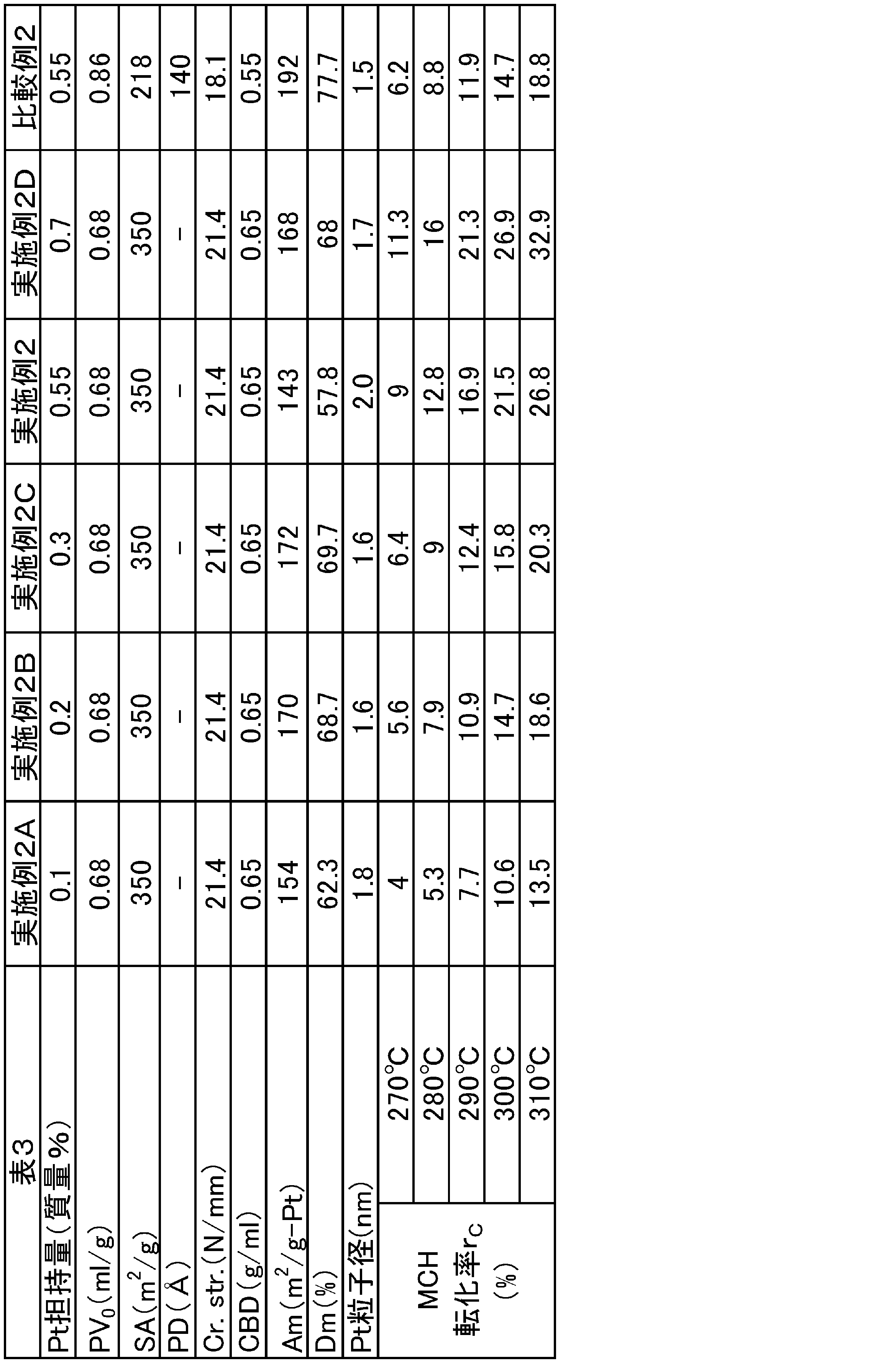
[Ptの粒子径分布及び平均粒子径の測定]
未使用の実施例2の脱水素触媒を、透過型電子顕微鏡(TEM)により撮影して、TEM画像を得た。未使用の脱水素触媒とは、焼成直後(工程(3)直後)の脱水素触媒であって、下記の還元処理を施す前の脱水素触媒を意味する。得られたTEM画像を画像解析ソフトで処理して、脱水素触媒に担持されている個々のPt粒子の粒子径を測定した。測定された個々のPt粒子(複数のPt粒子)の粒子径から、Pt粒子の粒子径分布及び平均粒子径を求めた。実施例2と同様の方法で、焼成直後の比較例2の脱水素触媒に担持されているPt粒子の粒子径分布及び平均粒子径を求めた。
未使用の実施例2の脱水素触媒を、透過型電子顕微鏡(TEM)により撮影して、TEM画像を得た。未使用の脱水素触媒とは、焼成直後(工程(3)直後)の脱水素触媒であって、下記の還元処理を施す前の脱水素触媒を意味する。得られたTEM画像を画像解析ソフトで処理して、脱水素触媒に担持されている個々のPt粒子の粒子径を測定した。測定された個々のPt粒子(複数のPt粒子)の粒子径から、Pt粒子の粒子径分布及び平均粒子径を求めた。実施例2と同様の方法で、焼成直後の比較例2の脱水素触媒に担持されているPt粒子の粒子径分布及び平均粒子径を求めた。
次いで、焼成直後の実施例2の脱水素触媒を、還元雰囲気下において、250℃で0.5時間加熱した。以下、この処理を還元処理という。この還元処理直後の実施例2の脱水素触媒に担持されているPt粒子の粒子径分布及び平均粒子径を上記と同様の方法で求めた。実施例2と同様の方法で、還元処理直後の比較例2の脱水素触媒に担持されているPt粒子の粒子径分布及び平均粒子径を求めた。
次いで、焼成直後の実施例2の脱水素触媒を用いて、以下の脱水素反応を行った。まず、脱水素触媒4ccを固定床流通式の反応器内に充填した。次に、MCH及び水素の混合ガス(nH/nMは0.7)を反応器内へ供給しながら、触媒層の中央部の出口温度を340℃に維持して、反応器内でMCHの脱水素反応を継続させた。反応圧力は0.19MPaGであった。反応器内へ供給するMCHの液空間速度(LHSV)を1.5h-1に維持した。反応開始から100時間が経過した時点で反応器から脱水素触媒を取り出した。以上の脱水素反応後の実施例2の脱水素触媒に担持されているPt粒子の粒子径分布及び平均粒子径を上記と同様の方法で求めた。実施例2と同様の方法で、脱水素反応後の比較例2の脱水素触媒に担持されているPt粒子の粒子径分布及び平均粒子径を求めた。
焼成直後の実施例2の脱水素触媒のTEM画像を図3中の(a)に示す。還元処理直後の実施例2の脱水素触媒のTEM画像を図3中の(b)に示す。脱水素反応後の実施例2の脱水素触媒のTEM画像を図3中の(c)に示す。焼成直後の比較例2の脱水素触媒のTEM画像を図4中の(a)に示す。還元処理直後の比較例2の脱水素触媒のTEM画像を図4中の(b)に示す。脱水素反応後の比較例2の脱水素触媒のTEM画像を図4中の(c)に示す。なお、図3及び4に示す各TEM画像において、白い点はPt粒子を示している。TEM画像において白い点がPt粒子を示すことは、EDXによる面分析によって確認した。つまり、HAADF-STEM画像における白い点が、EDXによる面分析によって得られたPtの分布とほぼ重なることを確認した。また、EDXによる面分析によって、還元処理直後の実施例2の脱水素触媒中にTiが均一に分散されていることを確認した。HAADF-STEMにより撮影した、還元処理直後の実施例2の脱水素触媒の画像を図5中の(a)に示す。HAADF-STEMにより撮影した、還元処理直後の比較例2の脱水素触媒の画像を図5中の(b)に示す。実施例2の脱水素触媒に担持されているPt粒子の粒子径分布(焼成直後、還元処理直後、及び脱水素反応後のそれぞれの時点におけるPt粒子の粒子径分布)を図6に示す。比較例2の脱水素触媒に担持されているPt粒子の粒子径分布(焼成直後、還元処理直後、及び脱水素反応後のそれぞれの時点におけるPt粒子の粒子径分布)を図7に示す。
焼成直後の実施例2の脱水素触媒に担持されているPt粒子の平均粒子径は2.0nmであった。焼成直後の実施例2の脱水素触媒に担持されているPt粒子の平均粒子径の標準偏差は0.47nmであった。還元処理直後の実施例2の脱水素触媒に担持されているPt粒子の平均粒子径は2.1nmであった。還元処理直後の実施例2の脱水素触媒に担持されているPt粒子の平均粒子径の標準偏差は0.52nmであった。脱水素反応後の実施例2の脱水素触媒に担持されているPt粒子の平均粒子径は2.1nmであった。脱水素反応後の実施例2の脱水素触媒に担持されているPt粒子の平均粒子径の標準偏差は0.52nmであった。焼成直後の比較例2の脱水素触媒に担持されているPt粒子の平均粒子径は1.5nmであった。焼成直後の比較例2の脱水素触媒に担持されているPt粒子の平均粒子径の標準偏差は0.26nmであった。還元処理直後の比較例2の脱水素触媒に担持されているPt粒子の平均粒子径は1.6nmであった。還元処理直後の比較例2の脱水素触媒に担持されているPt粒子の平均粒子径の標準偏差は0.32nmであった。脱水素反応後の比較例2の脱水素触媒に担持されているPt粒子の平均粒子径は1.7nmであった。脱水素反応後の比較例2の脱水素触媒に担持されているPt粒子の平均粒子径の標準偏差は0.42nmであった。
図7に示すように、比較例2の脱水素反応後の粒子径分布曲線は、比較例2の還元処理直後の粒子径分布曲線に比べて、正の方向にシフトしていることが確認された。つまり、比較例2の脱水素触媒では、脱水素反応によってPt粒子の粒子径が増加する傾向があることがわかった。図6に示すように、実施例2の脱水素反応後の粒子径分布曲線は、実施例2の還元処理直後の粒子径分布曲線に比べて、シフトしないことが確認された。つまり、実施例2の脱水素触媒では、還元処理直後と脱水素反応後とでPt粒子の粒子径が変化しない傾向があることがわかった。
以上のことから、実施例2の脱水素触媒に還元処理を施すと、脱水素触媒に担持されているPtが担体に固定化されることがわかった。還元処理後にPtが担体に固定化されるのは、実施例2の脱水素触媒がTiを含むことに因るものと考えられる。
[XPSによるPtの分析]
焼成直後の実施例2の脱水素触媒のXPSスペクトルを、XPS装置を用いて測定した。XPS装置としては、PHI製のQuantum-2000を用いた。X線源としては、Monochromated-Al-Kα線を用いた。帯電補正は、Al2O3由来のAlのエネルギー準位2sの電子に由来するピーク位置を119.7eVとして実施した。実施例2と同様の方法で、焼成直後の比較例2の脱水素触媒のXPSスペクトルを測定した。測定では、脱水素触媒の試料を導電性テープで固定した。上記以外のXPSの測定条件は以下のとおりであった。
X線源のエネルギー:1486.6eV
X線源の出力:40W
光電子の取り出し角度:45°
測定深さ:約4nm
測定エリア:φ100μm、楕円形
焼成直後の実施例2の脱水素触媒のXPSスペクトルを、XPS装置を用いて測定した。XPS装置としては、PHI製のQuantum-2000を用いた。X線源としては、Monochromated-Al-Kα線を用いた。帯電補正は、Al2O3由来のAlのエネルギー準位2sの電子に由来するピーク位置を119.7eVとして実施した。実施例2と同様の方法で、焼成直後の比較例2の脱水素触媒のXPSスペクトルを測定した。測定では、脱水素触媒の試料を導電性テープで固定した。上記以外のXPSの測定条件は以下のとおりであった。
X線源のエネルギー:1486.6eV
X線源の出力:40W
光電子の取り出し角度:45°
測定深さ:約4nm
測定エリア:φ100μm、楕円形
次いで、上記の還元処理直後の実施例2の脱水素触媒のXPSスペクトルを、上記と同様の方法で測定した。実施例2と同様の方法で、上記の還元処理直後の比較例2の脱水素触媒のXPSスペクトルを測定した。
次いで、上記の脱水素反応後の実施例2の脱水素触媒のXPSスペクトルを、上記と同様の方法で測定した。実施例2と同様の方法で、上記の脱水素反応後の比較例2の脱水素触媒のXPSスペクトルを測定した。
実施例2の脱水素触媒のXPSスペクトル(焼成直後、還元処理直後、及び脱水素反応後のそれぞれの時点における脱水素触媒のXPSスペクトル)を図8に示す。比較例2の脱水素触媒のXPSスペクトル(焼成直後、還元処理直後、及び脱水素反応後のそれぞれの時点における脱水素触媒のXPSスペクトル)を図9に示す。
実施例2の脱水素触媒のXPSスペクトルの測定結果を下記表4に示す。比較例2の脱水素触媒のXPSスペクトルの測定結果を下記表5に示す。表4又は5中、O(1s)の対Al比とは、XPSスペクトルにおいて、Oのエネルギー準位1sの電子に由来するピーク強度を、Alのエネルギー準位2sの電子に由来するピーク強度で割った値である。O(1s)の含有率とは、対Al比に基づいて算出した、脱水素触媒におけるOの含有率である。Pt(4d5/2)の対Al比とは、XPSスペクトルにおいて、Ptのエネルギー準位4d5/2の電子に由来するピーク強度を、Alのエネルギー準位2sの電子に由来するピーク強度で割った値である。Pt(4d5/2)の含有率とは、対Al比に基づいて算出した、脱水素触媒におけるPtの含有率である。Si(2s)の対Al比とは、XPSスペクトルにおいて、Siのエネルギー準位2sの電子に由来するピーク強度を、Alのエネルギー準位2sの電子に由来するピーク強度で割った値である。Si(2s)の含有率とは、対Al比に基づいて算出した、脱水素触媒におけるSiの含有率である。Ti(2p3/2)の対Al比とは、XPSスペクトルにおいて、Tiのエネルギー準位2p3/2の電子に由来するピーク強度を、Alのエネルギー準位2sの電子に由来するピーク強度で割った値である。Ti(2p3/2)の含有率とは、対Al比に基づいて算出した、脱水素触媒におけるTiの含有率である。C(1s)の対Al比とは、XPSスペクトルにおいて、Cのエネルギー準位1sの電子に由来するピーク強度を、Alのエネルギー準位2sの電子に由来するピーク強度で割った値である。C(1s)の含有率とは、対Al比に基づいて算出した、脱水素触媒におけるCの含有率である。
表4及び5から明らかなように、焼成直後の実施例2の脱水素触媒のXPSスペクトルにおいてPtの4d5/2電子に由来するピーク位置は、焼成直後の比較例2の脱水素触媒のXPSスペクトルにおいてPtの4d5/2電子に由来するピーク位置に比べて、0.4eV小さかった。還元処理直後の実施例2の脱水素触媒のXPSスペクトルにおいてPtの4d5/2電子に由来するピーク位置は、還元処理直後の比較例2の脱水素触媒のXPSスペクトルにおいてPtの4d5/2電子に由来するピーク位置に比べて、0.4eV小さかった。脱水素反応後の実施例2の脱水素触媒のXPSスペクトルにおいてPtの4d5/2電子に由来するピーク位置は、脱水素反応後の比較例2の脱水素触媒のXPSスペクトルにおいてPtの4d5/2電子に由来するピーク位置に比べて、0.7eV小さかった。
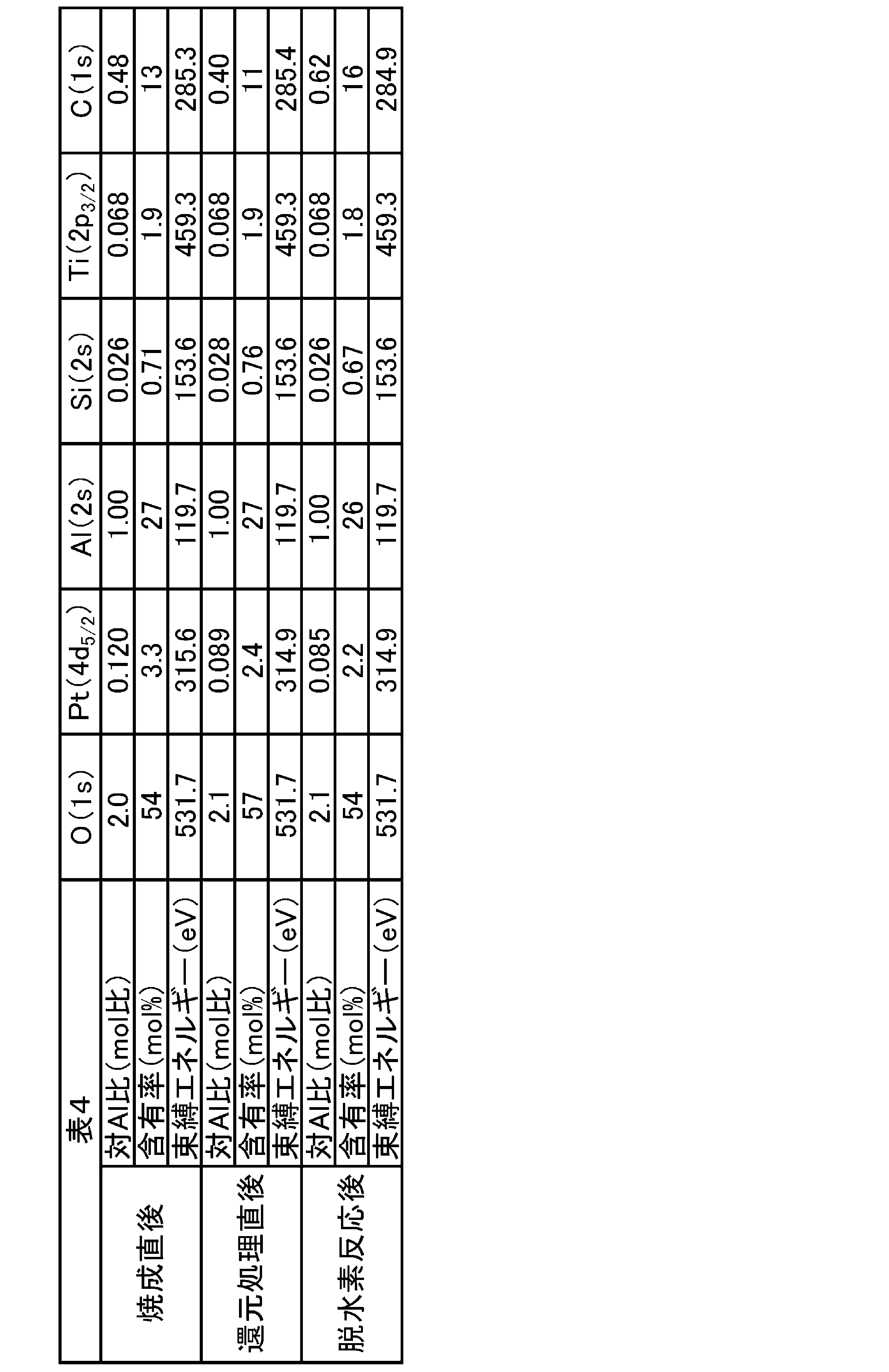
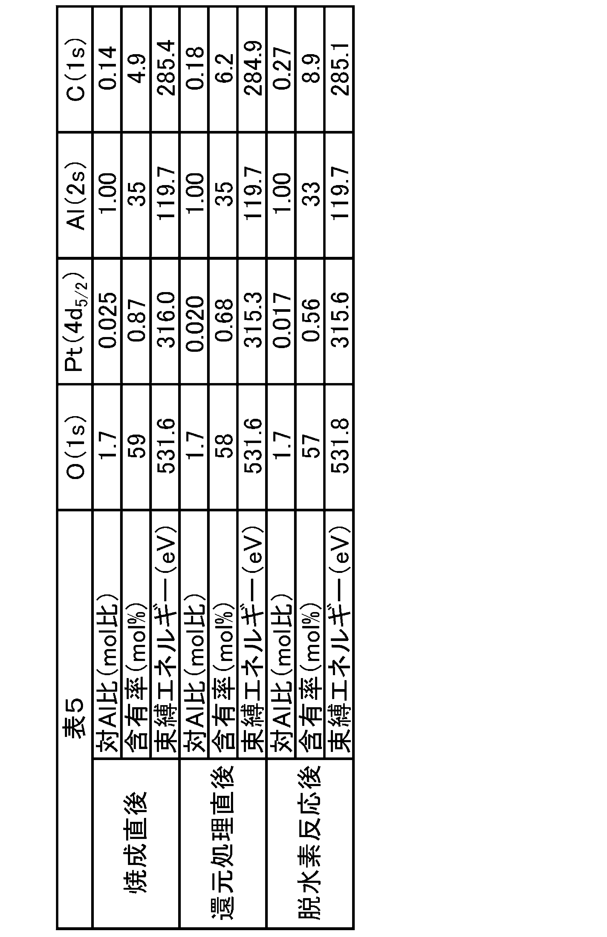
(実施例5)
下記に示す組成を有する担体を得るために、工程(1)において、水溶液Bにおける珪酸イオン及びアルミニウムイオンの濃度、並びに、水溶液Aにおけるチタニウムイオン及びアルミニウムイオンの濃度を調整した。この点を除いて実施例1と同様にして、実施例5の担体を得た。担体中のTiO2の含有量は15質量%であった。担体中のSiO2の含有量は3質量%であった。担体中のAl2O3の含有量は82質量%であった。また、実施例1と同様にして、実施例5のA1/A2及びA1/A0を算出した。A1/A2は0であった。A1/A0は0であった。続いて、実施例1と同様にして、実施例5の脱水素触媒を得た。
下記に示す組成を有する担体を得るために、工程(1)において、水溶液Bにおける珪酸イオン及びアルミニウムイオンの濃度、並びに、水溶液Aにおけるチタニウムイオン及びアルミニウムイオンの濃度を調整した。この点を除いて実施例1と同様にして、実施例5の担体を得た。担体中のTiO2の含有量は15質量%であった。担体中のSiO2の含有量は3質量%であった。担体中のAl2O3の含有量は82質量%であった。また、実施例1と同様にして、実施例5のA1/A2及びA1/A0を算出した。A1/A2は0であった。A1/A0は0であった。続いて、実施例1と同様にして、実施例5の脱水素触媒を得た。
(実施例6)
下記に示す組成を有する担体を得るために、工程(1)において、水溶液Bにおける珪酸イオン及びアルミニウムイオンの濃度、並びに、水溶液Aにおけるチタニウムイオン及びアルミニウムイオンの濃度を調整した。この点を除いて実施例1と同様にして、実施例6の担体を得た。担体中のTiO2の含有量は25質量%であった。担体中のSiO2の含有量は3質量%であった。担体中のAl2O3の含有量は72質量%であった。また、実施例1と同様にして、実施例6のA1/A2及びA1/A0を算出した。A1/A2は0であった。A1/A0は0であった。続いて、実施例1と同様にして、実施例6の脱水素触媒を得た。
下記に示す組成を有する担体を得るために、工程(1)において、水溶液Bにおける珪酸イオン及びアルミニウムイオンの濃度、並びに、水溶液Aにおけるチタニウムイオン及びアルミニウムイオンの濃度を調整した。この点を除いて実施例1と同様にして、実施例6の担体を得た。担体中のTiO2の含有量は25質量%であった。担体中のSiO2の含有量は3質量%であった。担体中のAl2O3の含有量は72質量%であった。また、実施例1と同様にして、実施例6のA1/A2及びA1/A0を算出した。A1/A2は0であった。A1/A0は0であった。続いて、実施例1と同様にして、実施例6の脱水素触媒を得た。
[メタン生成量の測定]
上記の実施例1~3、5、6及び比較例2それぞれの脱水素触媒を個別に用いて脱水素反応を行った。そして、脱水素反応に伴うメタン生成量を測定した。測定は、以下の方法により行った。脱水素触媒10mLを固定床流通式の反応器内に充填した。用いた反応器は管状であった。反応器の外径は1/2φであった。MCH及び水素の混合ガスを反応器内へ供給して、脱水素反応を行った。脱水素反応は335℃の温度で行った。混合ガスにおけるnH/nMは0.713であった。反応圧力は0.15MPaGであった。反応器内へ供給するMCHの液空間速度(LHSV)を1.5h-1に維持した。反応開始から55時間が経過した時点で、反応器から排出された生成物を回収した。生成物を、ガスクロマトグラフ-水素炎イオン化検出器(GC-FID)で分析した。生成物に含まれるメタンのピーク面積から、検量線を用いて生成ガス中のメタン濃度(molppm)を算出した。生成ガス中のメタン濃度(molppm)の値が小さいほど、脱水素反応に伴う脱メチル化がより抑制されている。
上記の実施例1~3、5、6及び比較例2それぞれの脱水素触媒を個別に用いて脱水素反応を行った。そして、脱水素反応に伴うメタン生成量を測定した。測定は、以下の方法により行った。脱水素触媒10mLを固定床流通式の反応器内に充填した。用いた反応器は管状であった。反応器の外径は1/2φであった。MCH及び水素の混合ガスを反応器内へ供給して、脱水素反応を行った。脱水素反応は335℃の温度で行った。混合ガスにおけるnH/nMは0.713であった。反応圧力は0.15MPaGであった。反応器内へ供給するMCHの液空間速度(LHSV)を1.5h-1に維持した。反応開始から55時間が経過した時点で、反応器から排出された生成物を回収した。生成物を、ガスクロマトグラフ-水素炎イオン化検出器(GC-FID)で分析した。生成物に含まれるメタンのピーク面積から、検量線を用いて生成ガス中のメタン濃度(molppm)を算出した。生成ガス中のメタン濃度(molppm)の値が小さいほど、脱水素反応に伴う脱メチル化がより抑制されている。
実施例1の生成ガス中のメタン濃度は181.1molppmであった。実施例2の生成ガス中のメタン濃度は129.5molppmであった。実施例3の生成ガス中のメタン濃度は77.7molppmであった。実施例5の生成ガス中のメタン濃度は108.0molppmであった。実施例6の生成ガス中のメタン濃度は55.0molppmであった。比較例2の生成ガス中のメタン濃度は240.7molppmであった。実施例1~3、5、6及び比較例2それぞれの担体中のTiO2の含有量(質量%)と、生成ガス中のメタン濃度(molppm)との関係を図11に示す。図11が示す通り、実施例1~3、5及び6は、比較例2に比べて、脱水素反応に伴う脱メチル化を抑制できることがわかった。また、担体中のTiO2の含有量を増加させると、脱水素反応に伴う脱メチル化をより抑制できることがわかった。
2…脱水素反応器、4…気液分離器、6…水素精製装置、14…高圧コンプレッサー、16…タンク、100…水素の製造システム、200…担体。
Claims (11)
- 担体と、前記担体に担持された短周期表第VIII族元素と、を備える、炭化水素用の脱水素触媒であって、
前記担体が、Al2O3及びTiO2を含み、
前記脱水素触媒のX線回折パターンにおいて、アナターゼ型TiO2の(101)面に由来する回折ピークの面積がA1であり、
前記脱水素触媒のX線回折パターンにおいて、γ-Al2O3の(400)面に由来する回折ピークの面積がA2であるとき、
A1/A2が0.17未満である、
炭化水素用の脱水素触媒。 - アナターゼ型TiO2のX線回折パターンにおいて、アナターゼ型TiO2の(101)面に由来する回折ピークの面積がA0であるとき、
A1/A0が59/1000未満である、
請求項1に記載の脱水素触媒。 - 前記担体が、更にSiO2を含む、
請求項1又は2に記載の脱水素触媒。 - 前記担体におけるTiの含有量が、前記担体の全質量を基準として、酸化物換算で、3~40質量%である、
請求項1~3のいずれか一項に記載の脱水素触媒。 - 前記短周期表第VIII族元素がPtである、
請求項1~4のいずれか一項に記載の脱水素触媒。 - 前記担体におけるAlの含有量が、前記担体の全質量を基準として、酸化物換算で、50~96質量%であり、
前記担体におけるSiの含有量が、前記担体の全質量を基準として、酸化物換算で、1~10質量%である、
請求項1~5のいずれか一項に記載の脱水素触媒。 - 前記短周期表第VIII族元素の担持量が、前記脱水素触媒の全質量を基準として、0.1~1質量%である、
請求項1~6のいずれか一項に記載の脱水素触媒。 - 請求項1~7のいずれか一項に記載の脱水素触媒を有し、前記脱水素触媒を用いた前記炭化水素の脱水素により、水素を生成させる脱水素反応器を備える、
水素の製造システム。 - 請求項1~7のいずれか一項に記載の脱水素触媒を用いた炭化水素の脱水素により、水素を生成させる工程を備える、
水素の製造方法。 - 反応温度250~420℃、水素分圧0.1~1.0MPa、液空間速度0.2~4.0h-1、及び、水素/炭化水素モル比0.05~1.0の条件下で、前記炭化水素と前記脱水素触媒とを接触させる、
請求項9に記載の水素の製造方法。 - 前記炭化水素が、ナフテン系炭化水素である、
請求項9又は10に記載の水素の製造方法。
Priority Applications (1)
| Application Number | Priority Date | Filing Date | Title |
|---|---|---|---|
| JP2017509546A JP6792550B2 (ja) | 2015-03-27 | 2016-03-17 | 炭化水素用の脱水素触媒、水素の製造システム及び水素の製造方法 |
Applications Claiming Priority (4)
| Application Number | Priority Date | Filing Date | Title |
|---|---|---|---|
| JP2015-067004 | 2015-03-27 | ||
| JP2015067004 | 2015-03-27 | ||
| JP2015-206673 | 2015-10-20 | ||
| JP2015206673 | 2015-10-20 |
Publications (1)
| Publication Number | Publication Date |
|---|---|
| WO2016158437A1 true WO2016158437A1 (ja) | 2016-10-06 |
Family
ID=57006746
Family Applications (1)
| Application Number | Title | Priority Date | Filing Date |
|---|---|---|---|
| PCT/JP2016/058444 Ceased WO2016158437A1 (ja) | 2015-03-27 | 2016-03-17 | 炭化水素用の脱水素触媒、水素の製造システム及び水素の製造方法 |
Country Status (2)
| Country | Link |
|---|---|
| JP (1) | JP6792550B2 (ja) |
| WO (1) | WO2016158437A1 (ja) |
Cited By (4)
| Publication number | Priority date | Publication date | Assignee | Title |
|---|---|---|---|---|
| JP2019042705A (ja) * | 2017-09-05 | 2019-03-22 | Jxtgエネルギー株式会社 | 脱水素触媒、水素の製造システム、及び水素の製造方法 |
| JP2022531799A (ja) * | 2019-05-06 | 2022-07-11 | 中国石油化工股▲ふん▼有限公司 | 有機水素吸蔵原料用脱水素触媒及びその担体、水素吸蔵性合金、並びに、高純度水素ガスの供給方法 |
| WO2022219822A1 (ja) * | 2021-04-16 | 2022-10-20 | 千代田化工建設株式会社 | 水素ステーション及び水素生成方法 |
| US12365968B2 (en) | 2019-05-06 | 2025-07-22 | China Petroleum & Chemical Corporation | Organic hydrogen storage material dehydrogenation catalyst, support for the catalyst, hydrogen-storage alloy, and process for providing high-purity hydrogen gas |
Families Citing this family (1)
| Publication number | Priority date | Publication date | Assignee | Title |
|---|---|---|---|---|
| JP7472399B2 (ja) * | 2021-04-16 | 2024-04-22 | 千代田化工建設株式会社 | 白金担持アルミナ触媒及びその製造方法ならびにその触媒を用いた水素化芳香族類の脱水素方法 |
Citations (6)
| Publication number | Priority date | Publication date | Assignee | Title |
|---|---|---|---|---|
| JPH07300433A (ja) * | 1994-04-28 | 1995-11-14 | Inst Fr Petrole | C4〜C5のn−パラフィンの脱水素異性化における触媒の使用法 |
| JPH11507590A (ja) * | 1995-06-16 | 1999-07-06 | アンスティテュー フランセ デュ ペトロール | 炭化水素変換反応用のチタン、ジルコニウム、ハフニウム、コバルト、ニッケル、亜鉛、ランタニド類並びにアルカリ及びアルカリ土類金属からなる群から選択されるドーピング金属を含む触媒 |
| JPH11507591A (ja) * | 1995-06-16 | 1999-07-06 | アンスティテュー フランセ デュ ペトロール | 炭化水素の転化反応に使用可能なケイ素含有触媒 |
| JP2006232607A (ja) * | 2005-02-24 | 2006-09-07 | Japan Energy Corp | 水素製造方法 |
| JP2010006651A (ja) * | 2008-06-27 | 2010-01-14 | Japan Energy Corp | 水素製造装置および水素製造方法 |
| CN103214336A (zh) * | 2013-01-09 | 2013-07-24 | 北京石油化工学院 | 环己烷氧化脱氢制环己烯的方法 |
-
2016
- 2016-03-17 JP JP2017509546A patent/JP6792550B2/ja active Active
- 2016-03-17 WO PCT/JP2016/058444 patent/WO2016158437A1/ja not_active Ceased
Patent Citations (6)
| Publication number | Priority date | Publication date | Assignee | Title |
|---|---|---|---|---|
| JPH07300433A (ja) * | 1994-04-28 | 1995-11-14 | Inst Fr Petrole | C4〜C5のn−パラフィンの脱水素異性化における触媒の使用法 |
| JPH11507590A (ja) * | 1995-06-16 | 1999-07-06 | アンスティテュー フランセ デュ ペトロール | 炭化水素変換反応用のチタン、ジルコニウム、ハフニウム、コバルト、ニッケル、亜鉛、ランタニド類並びにアルカリ及びアルカリ土類金属からなる群から選択されるドーピング金属を含む触媒 |
| JPH11507591A (ja) * | 1995-06-16 | 1999-07-06 | アンスティテュー フランセ デュ ペトロール | 炭化水素の転化反応に使用可能なケイ素含有触媒 |
| JP2006232607A (ja) * | 2005-02-24 | 2006-09-07 | Japan Energy Corp | 水素製造方法 |
| JP2010006651A (ja) * | 2008-06-27 | 2010-01-14 | Japan Energy Corp | 水素製造装置および水素製造方法 |
| CN103214336A (zh) * | 2013-01-09 | 2013-07-24 | 北京石油化工学院 | 环己烷氧化脱氢制环己烯的方法 |
Cited By (7)
| Publication number | Priority date | Publication date | Assignee | Title |
|---|---|---|---|---|
| JP2019042705A (ja) * | 2017-09-05 | 2019-03-22 | Jxtgエネルギー株式会社 | 脱水素触媒、水素の製造システム、及び水素の製造方法 |
| JP2022531799A (ja) * | 2019-05-06 | 2022-07-11 | 中国石油化工股▲ふん▼有限公司 | 有機水素吸蔵原料用脱水素触媒及びその担体、水素吸蔵性合金、並びに、高純度水素ガスの供給方法 |
| JP7576568B2 (ja) | 2019-05-06 | 2024-10-31 | 中国石油化工股▲ふん▼有限公司 | 有機水素吸蔵原料用脱水素触媒及びその担体、水素吸蔵性合金、並びに、高純度水素ガスの供給方法 |
| US12365968B2 (en) | 2019-05-06 | 2025-07-22 | China Petroleum & Chemical Corporation | Organic hydrogen storage material dehydrogenation catalyst, support for the catalyst, hydrogen-storage alloy, and process for providing high-purity hydrogen gas |
| US12371762B2 (en) | 2019-05-06 | 2025-07-29 | China Petroleum & Chemical Corporation | Organic hydrogen storage material dehydrogenation catalyst, support for the catalyst, hydrogen-storage alloy, and process for providing high-purity hydrogen gas |
| US12383887B2 (en) | 2019-05-06 | 2025-08-12 | China Petroleum & Chemical Corporation | Organic hydrogen storage material dehydrogenation catalyst, support for the catalyst, hydrogen-storage alloy, and process for providing high purity hydrogen gas |
| WO2022219822A1 (ja) * | 2021-04-16 | 2022-10-20 | 千代田化工建設株式会社 | 水素ステーション及び水素生成方法 |
Also Published As
| Publication number | Publication date |
|---|---|
| JPWO2016158437A1 (ja) | 2018-01-18 |
| JP6792550B2 (ja) | 2020-11-25 |
Similar Documents
| Publication | Publication Date | Title |
|---|---|---|
| Saadatjou et al. | Ruthenium nanocatalysts for ammonia synthesis: a review | |
| Zhen et al. | Enhancing activity for carbon dioxide methanation by encapsulating (1 1 1) facet Ni particle in metal–organic frameworks at low temperature | |
| Wang et al. | Ni single atoms confined in nitrogen-doped carbon nanotubes for active and selective hydrogenation of CO2 to CO | |
| JP4907210B2 (ja) | 水素の貯蔵輸送システム | |
| JP6792550B2 (ja) | 炭化水素用の脱水素触媒、水素の製造システム及び水素の製造方法 | |
| Varisli et al. | Hydrogen from ammonia over cobalt incorporated silicate structured catalysts prepared using different cobalt salts | |
| Furusawa et al. | Preparation of Ru/ZrO2 catalysts by NaBH4 reduction and their catalytic activity for NH3 decomposition to produce H2 | |
| Chen et al. | Biogas dry reforming for syngas production: catalytic performance of nickel supported on waste-derived SiO 2 | |
| WO2014157202A1 (ja) | ナフテン系炭化水素用の脱水素触媒、ナフテン系炭化水素用の脱水素触媒の製造方法、水素の製造システム、及び水素の製造方法 | |
| Snytnikov et al. | CO-cleanup of hydrogen-rich stream for LT PEM FC feeding: catalysts and their performance in selective CO methanation | |
| Sibi et al. | Single-step catalytic liquid-phase hydroconversion of DCPD into high energy density fuel exo-THDCPD | |
| US7196036B2 (en) | Catalyst for decomposition of hydrocarbons, process for producing the catalyst, and process for producing hydrogen using the catalyst | |
| Park et al. | Synthesis of Co/SiO2 hybrid nanocatalyst via twisted Co3Si2O5 (OH) 4 nanosheets for high-temperature Fischer–Tropsch reaction | |
| Sukri et al. | Effect of cobalt loading on suppression of carbon formation in carbon dioxide reforming of methane over Co/MgO catalyst | |
| US12134085B2 (en) | Steam reforming catalysts for sustainable hydrogen production from biobased materials | |
| Lee et al. | Top-down syntheses of nickel-based structured catalysts for hydrogen production from ammonia | |
| Han et al. | Low CO content hydrogen production from oxidative steam reforming of ethanol over CuO-CeO2 catalysts at low-temperature | |
| Ajeebi et al. | Alumina-supported bimetallic catalysts with ruthenium and CoNi for enhanced ammonia decomposition | |
| Li et al. | Effect of zinc incorporation manner on a Cu–ZnO/Al2O3 glycerol hydrogenation catalyst | |
| Choi et al. | Direct synthesis of vertically oriented Co-Mg-Al layered double hydroxide on spherical γ-Al2O3 for passive NOx adsorber | |
| Li et al. | Catalytic decomposition of ammonia over fly ash supported Ru catalysts | |
| An et al. | Novel highly dispersed Ni-based oxides catalysts for ethanol steam reforming | |
| Wang et al. | Effect of ZnZrO x nanocrystal size on catalytic performance in the production of light olefins from carbon dioxide | |
| Liu et al. | Modified iron-molybdate catalysts with various metal oxides by a mechanochemical method: enhanced formaldehyde yield in methanol partial oxidation | |
| JP2016209786A (ja) | 脱水素触媒、水素の製造システム、及び水素の製造方法 |
Legal Events
| Date | Code | Title | Description |
|---|---|---|---|
| 121 | Ep: the epo has been informed by wipo that ep was designated in this application |
Ref document number: 16772320 Country of ref document: EP Kind code of ref document: A1 |
|
| ENP | Entry into the national phase |
Ref document number: 2017509546 Country of ref document: JP Kind code of ref document: A |
|
| NENP | Non-entry into the national phase |
Ref country code: DE |
|
| 122 | Ep: pct application non-entry in european phase |
Ref document number: 16772320 Country of ref document: EP Kind code of ref document: A1 |