WO2016158239A1 - 遊星歯車装置 - Google Patents
遊星歯車装置 Download PDFInfo
- Publication number
- WO2016158239A1 WO2016158239A1 PCT/JP2016/057138 JP2016057138W WO2016158239A1 WO 2016158239 A1 WO2016158239 A1 WO 2016158239A1 JP 2016057138 W JP2016057138 W JP 2016057138W WO 2016158239 A1 WO2016158239 A1 WO 2016158239A1
- Authority
- WO
- WIPO (PCT)
- Prior art keywords
- inward flange
- planetary gear
- flange
- valley
- ring gear
- Prior art date
Links
Images


Classifications
-
- F—MECHANICAL ENGINEERING; LIGHTING; HEATING; WEAPONS; BLASTING
- F16—ENGINEERING ELEMENTS AND UNITS; GENERAL MEASURES FOR PRODUCING AND MAINTAINING EFFECTIVE FUNCTIONING OF MACHINES OR INSTALLATIONS; THERMAL INSULATION IN GENERAL
- F16H—GEARING
- F16H1/00—Toothed gearings for conveying rotary motion
- F16H1/28—Toothed gearings for conveying rotary motion with gears having orbital motion
- F16H1/2809—Toothed gearings for conveying rotary motion with gears having orbital motion with means for equalising the distribution of load on the planet-wheels
- F16H1/2818—Toothed gearings for conveying rotary motion with gears having orbital motion with means for equalising the distribution of load on the planet-wheels by allowing limited movement of the ring gear relative to the casing or shaft
-
- F—MECHANICAL ENGINEERING; LIGHTING; HEATING; WEAPONS; BLASTING
- F16—ENGINEERING ELEMENTS AND UNITS; GENERAL MEASURES FOR PRODUCING AND MAINTAINING EFFECTIVE FUNCTIONING OF MACHINES OR INSTALLATIONS; THERMAL INSULATION IN GENERAL
- F16H—GEARING
- F16H57/00—General details of gearing
- F16H57/02—Gearboxes; Mounting gearing therein
- F16H57/023—Mounting or installation of gears or shafts in the gearboxes, e.g. methods or means for assembly
-
- F—MECHANICAL ENGINEERING; LIGHTING; HEATING; WEAPONS; BLASTING
- F16—ENGINEERING ELEMENTS AND UNITS; GENERAL MEASURES FOR PRODUCING AND MAINTAINING EFFECTIVE FUNCTIONING OF MACHINES OR INSTALLATIONS; THERMAL INSULATION IN GENERAL
- F16H—GEARING
- F16H57/00—General details of gearing
- F16H57/08—General details of gearing of gearings with members having orbital motion
-
- F—MECHANICAL ENGINEERING; LIGHTING; HEATING; WEAPONS; BLASTING
- F02—COMBUSTION ENGINES; HOT-GAS OR COMBUSTION-PRODUCT ENGINE PLANTS
- F02C—GAS-TURBINE PLANTS; AIR INTAKES FOR JET-PROPULSION PLANTS; CONTROLLING FUEL SUPPLY IN AIR-BREATHING JET-PROPULSION PLANTS
- F02C7/00—Features, components parts, details or accessories, not provided for in, or of interest apart form groups F02C1/00 - F02C6/00; Air intakes for jet-propulsion plants
- F02C7/36—Power transmission arrangements between the different shafts of the gas turbine plant, or between the gas-turbine plant and the power user
-
- F—MECHANICAL ENGINEERING; LIGHTING; HEATING; WEAPONS; BLASTING
- F05—INDEXING SCHEMES RELATING TO ENGINES OR PUMPS IN VARIOUS SUBCLASSES OF CLASSES F01-F04
- F05D—INDEXING SCHEME FOR ASPECTS RELATING TO NON-POSITIVE-DISPLACEMENT MACHINES OR ENGINES, GAS-TURBINES OR JET-PROPULSION PLANTS
- F05D2260/00—Function
- F05D2260/40—Transmission of power
- F05D2260/403—Transmission of power through the shape of the drive components
- F05D2260/4031—Transmission of power through the shape of the drive components as in toothed gearing
- F05D2260/40311—Transmission of power through the shape of the drive components as in toothed gearing of the epicyclical, planetary or differential type
-
- F—MECHANICAL ENGINEERING; LIGHTING; HEATING; WEAPONS; BLASTING
- F16—ENGINEERING ELEMENTS AND UNITS; GENERAL MEASURES FOR PRODUCING AND MAINTAINING EFFECTIVE FUNCTIONING OF MACHINES OR INSTALLATIONS; THERMAL INSULATION IN GENERAL
- F16H—GEARING
- F16H55/00—Elements with teeth or friction surfaces for conveying motion; Worms, pulleys or sheaves for gearing mechanisms
- F16H55/02—Toothed members; Worms
- F16H55/17—Toothed wheels
- F16H2055/176—Ring gears with inner teeth
Definitions
- the present invention relates to a planetary gear device used in a power transmission mechanism such as an aircraft.
- this type of planetary gear device has a sun gear having external teeth, a plurality of planet gears having external teeth and meshing with the sun gear, and a rotating shaft of each planet gear supporting a plurality of planet gears.
- a common planet carrier for positioning and a ring gear having internal teeth and meshing with a plurality of planet gears are provided (for example, see Patent Document 1).
- Power generated by a power source such as a gas turbine engine is first input to the sun gear and then transmitted to the planet gear, for example.
- the power transmitted to the planet gear can be extracted as two different outputs, that is, the rotational power of the ring gear due to the rotation of the planet gear and the rotational power of the planet carrier due to the revolution of the planet gear relative to the sun gear.
- a bending moment acts on the engine during operation of the aircraft, and the engine structure Bending deformation occurs. Due to the influence of the bending deformation of the engine structure, the planetary gear device as a whole may also be bent, and due to this bending deformation, the parallelism between the planet gear and the sun gear and the ring gear meshing with the planet gear is shifted, that is, Misalignment occurs. When misalignment occurs, contact between gears and bearing pieces occurs.
- a radial load is periodically applied to the connecting portion between the ring gear and the cylindrical support member located on the outer peripheral portion of the planetary gear device, that is, the flange for bolt insertion, due to the revolution of the planet gear.
- the radial load causes a difference in radial displacement between the flange of the ring gear and the flange of the cylindrical support member. Fretting may occur between the two.
- An object of the present invention is to solve the above-mentioned problems, and can prevent fretting between the ring gear and the cylindrical support member without causing an increase in the weight of the entire apparatus, and can provide a planet with excellent life performance.
- the object is to provide a gear device.
- a planetary gear device includes a sun gear having outer teeth fixed concentrically to a power input shaft, and a plurality of gears having outer teeth and meshing with the sun gear.
- An outward flange projecting outward in the direction is provided over the entire circumference, and a corrugated inward flange having a plurality of projecting pieces projecting inward in the radial direction is provided over the entire circumference on the cylindrical support member.
- the ring gear and the cylindrical support member are connected by fastening the outward flange and the inward flange with bolts and nuts, and the inward In the lunge, a shallow first trough and a second trough deeper than the first trough are formed as the trough so that the depth of the trough between the plurality of protrusions is periodically increased.
- the depth of the valley means the radial position of the bottom (the outermost diameter side portion) of the valley that is recessed radially outward, and the depth of the valley is “deep”. “Means that the bottom of the valley is located on the outer diameter side, and“ the depth of the valley is “shallow” ”means that the bottom of the valley is located on the inner diameter side.
- the weight of the planetary gear device can be reduced while securing the rigidity of the ring gear by providing the corrugated flange on the outer peripheral portion of the ring gear.
- the rigidity of the projecting pieces required for the driving torque is ensured for the inward flange of the cylindrical support member. Meanwhile, the radial rigidity of the entire inward flange can be reduced, and the cylindrical support member can easily follow the deformation of the ring gear.
- the inward flange is formed with a plurality of bolt insertion holes through which the bolts are inserted, and the depth of the second valley portion circumscribes the plurality of bolt insertion holes. It may be set deeper than the circumference of the virtual circle, and the depth of the first valley may be set shallower than the circumference of the virtual circle. According to this configuration, the portion of the inner diameter side than the outermost diameter side portion of the bolt insertion hole is present in the shallow valley portion, so that the rigidity of the projecting piece necessary for suppressing the deformation caused by the drive torque is increased. It can be secured.
- a plurality of anti-rotation plates that prevent the nut from loosening are attached to the inward flange at predetermined intervals in the circumferential direction,
- the second valley is located in a circumferential portion where the detent plate is not present, and the first valley is located in a circumferential portion where the detent plate is present. Therefore, the inward flange may be formed such that the depth of the valley portion is periodically increased. According to this configuration, the rigidity of the inward flange of the cylindrical support member and the rigidity of the non-rotating plate can be reduced while improving the efficiency of the assembly work by providing the non-rotating plate and fixing the nut. Therefore, occurrence of fretting between the flange surfaces can be prevented.
- one of the detent plates is provided for two to five of the nuts arranged in succession, and arranged in succession at the inward flange.
- One second trough may be formed for every two to five troughs.
- an inner diameter side edge portion of the detent plate is formed in a corrugated shape having a ridge portion protruding in the radial direction of the support member and a valley portion recessed in the radial direction, and the detent plate Is arranged so that the circumferential position of the valley portion corresponds to the circumferential position of the valley portion of the inward flange, and the depth of the valley portion of the detent plate is inward of the support member. It may be shallower than the depth of the valley of the flange. According to this configuration, the strength of the detent plate made of a plate-like member having no cylindrical portion is sufficiently ensured.
- the detent plate is attached to the inward flange via a plurality of fixing pins provided on the inward flange, and each of the plurality of fixing pins includes the first fixing pin.
- FIG. 1 is a partially broken perspective view showing a planetary gear device according to an embodiment of the present invention. It is a longitudinal cross-sectional view of the planetary gear device of FIG. It is a longitudinal cross-sectional view which expands and shows the countersink periphery of the inward flange of the flex support of FIG.
- FIG. 1 It is a disassembled perspective view which shows the connection structure of the ring gear and flex support of the planetary gear apparatus of FIG. It is a front view which shows the inward flange of the flex support of FIG. It is a front view which shows the state which attached the detent
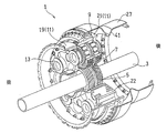
- FIG. 1 is a perspective view showing a planetary gear device 1 according to an embodiment of the present invention.
- the planetary gear device 1 is installed in, for example, a propeller-propelled aircraft engine and is connected to a gas turbine engine (not shown) via an input shaft 3.
- the power of the gas turbine engine is transmitted to two rotors (not shown). Are transmitted as outputs independent of each other.
- the planetary gear device 1 may be used to transmit power output to only one rotor.
- the axial side on which the gas turbine engine is disposed (left side in FIG. 1) is referred to as the front side, and the opposite side is referred to as the rear side.
- the “radial direction” refers to a radial direction centered on the same axis C1 as the input shaft 3 described later.
- FIG. 2 is a longitudinal sectional view showing the planetary gear device 1 of FIG.
- the planetary gear device 1 is configured as a double-row gear mechanism, and includes a sun gear 5, a plurality of planet gears 7, a ring gear 9, a planet carrier 11, and a planet shaft 13.
- the sun gear 5 is a gear having external teeth composed of double-row helical gears inclined in opposite directions, and is fitted to the outer periphery of the input shaft 3 serving as a rotating shaft.
- the planet gear 7 is a gear having a double row of external teeth made of a helical gear corresponding to the sun gear 5, and is rotatable on the outer periphery of a hollow planet shaft 13 serving as a rotation shaft via a double row bearing 15.
- the ring gear 9 is a gear having internal teeth composed of double rows of helical gears, and meshes with the planet gear 7.
- Each gear is not limited to a helical gear, and may be a spur gear, for example.
- Each planet shaft 13 of the plurality of planet gears 7 is supported at its front end by an annular front plate 17 having the same axis C1 as the input shaft 3.
- the front plate 17 is connected to an inner peripheral portion of a stub shaft 19 which is a cylindrical shaft arranged concentrically by a plurality of bolts.
- a back plate 21 is connected to the back side of the front plate 17.
- a plurality of support columns 22 (FIG. 1) are integrally formed on the back plate 21 at equal intervals in the circumferential direction, and the back plate 21 is bolted to the front plate 17 via these support columns 22.
- the back plate 21 supports the rear end of the planet shaft 13.
- the stub shaft 19 and the front plate 17 and the back plate 21 connected to each other via the stub shaft 19 constitute the planet carrier 11 that supports the planet shaft 13 and the planet gear 7.
- the planet carrier 11 determines the relative position between the planet shafts 13, that is, the relative position between the planet gears 7.
- the front end portion of the stub shaft 19 is connected to the front output shaft 23 concentric with the input shaft 3, and the power generated by the revolution of the plurality of planet gears 7 around the axis C 1 causes the stub shaft 19 and the front output shaft 23 to move. For example, it is output to the front propeller 26 as a driving force.
- the ring gear 9 is coupled to a flex support 27 that is a cylindrical support member disposed concentrically with the input shaft 3.
- the rear end portion of the flex support 27 is connected to a rear output shaft 29 concentric with the input shaft 3.
- the connection structure between the ring gear 9 and the flex support 27 will be described in detail later.
- the power generated by the rotation of the planet gear 7 around the rotation axis C2 is output to the rear propeller 32 as a driving force via the ring gear 9, the flex support 27 and the rear output shaft 29, for example.
- the entire planetary gear device 1 is supported from the front by the input shaft 3 and the stub shaft 19 and from the rear by the flex support 27 that supports the ring gear 9.
- the input shaft 3 and the stub shaft 19 (planet carrier 11) are formed as highly rigid members.
- the flex support 27 is formed as a low-rigidity member having a flexible structure portion 41 having a V-shaped longitudinal section that is recessed on the inner diameter side.
- the flex support 27 has a large-diameter cylindrical portion 43 formed on the ring gear 9 side and a small-diameter cylindrical portion 45 formed on the rear output side.
- a flexible structure 41 is formed between the two.
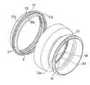
- an outward flange 51 projecting radially outward is provided on the outer peripheral portion of the ring gear 9.
- an inward flange 53 that protrudes radially inward is provided on the inner peripheral portion of the front end portion of the flex support 27.
- the outward flange 51 of the ring gear 9 is provided on the outer periphery of the ring gear 9 over the entire circumference.
- An inward flange 53 of the flex support 27 is provided on the inner peripheral portion of the flex support 27 over the entire circumference.
- the outward flange 51 and the inward flange 53 are each formed in a chevron shape in which a plurality of wave shapes are connected in the circumferential direction.
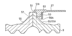
- the outward flange 51 of the ring gear 9 includes a flange main body 51 a that protrudes in a plate shape in the radial direction, and an annular connecting wall 55.
- the annular connecting wall 55 extends while being inclined in the axial direction from the surface of the flange body 51a facing the flex support 27 side.
- a plurality of valley portions 55a recessed toward the inner diameter side are formed at equal intervals over the entire circumference in the circumferential direction, and a portion between these valley portions 55a forms a peak portion 55b. . That is, in the outward flange 51, the trough portions 55a and the crest portions 55b of the annular connecting wall 55 are provided continuously at equal intervals over the entire circumference in the circumferential direction.
- the ring gear 9 By providing the ring gear 9 with the annular connecting wall 55, the axial end of the ring gear 9 is prevented from jumping up.
- bolt insertion holes 57 penetrating in the axial direction are provided at respective circumferential positions corresponding to the valley portions 55a of the connecting wall 55.
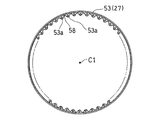
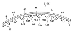
- the inward flange 53 of the flex support 27 is formed in a corrugated shape having a plurality of projecting pieces 53a projecting radially inward. These projecting pieces 53 a are provided at equal intervals over the entire circumference of the inward flange 53. As shown in FIG. 5, each projecting piece 53a of the inward flange 53 corresponds to a corrugated peak, and a corrugated trough (hereinafter referred to as “inward flange trough” between adjacent projecting pieces 53a, 53a. 58) is formed. Further, as shown in FIG. 3, each projecting piece 53a is provided with a bolt insertion hole 59 penetrating in the axial direction.
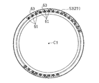
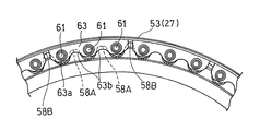
- a detent plate 63 that prevents the connection nut 61 from loosening is provided on the inward flange 53 side of the flex support 27.
- Each of the connecting nuts 61 is fixed to the anti-rotation plate 63 in a state of being anti-rotated by, for example, a rivet.
- the connection nut 61 may be fixed to the rotation stop plate 63 by other methods, for example, welding.
- the outward flange 51 and the inward flange 53 are arranged so that the peak portion of the inward flange 53 of the flex support 27, that is, the axial end surface of the projecting piece 53a overlaps the valley 55a of the outward flange 51 of the ring gear 9 shown in FIG. 3, the connecting bolt 65 is inserted into the bolt insertion holes 57 and 59 from the ring gear 9 side and screwed into the connecting nut 61 fixed to the rotation stop plate 63 as shown in FIG.
- the ring gear 9 and the flex support 27 are connected so as not to rotate relative to each other.
- the peak portion 55 b of the connection wall 55 enters the position of the inward flange valley portion 58. Thereby, interference with the inward flange 53 and the peak part 55b of the connection wall 55 is avoided.
- a plurality of detent plates 63 are provided at predetermined intervals in the circumferential direction.
- a plurality (three in the illustrated example) of connecting nuts 61 are attached to each of the detent plates 63.
- Each detent plate 63 is attached to the inward flange 53 of the flex support 27 by a fixing pin 67 shown in FIG.
- a plurality (two in the illustrated example) of fixing pins 67 are provided at positions spaced apart in the circumferential direction of the outer peripheral portion of one rotation stopper plate 63.
- the number and arrangement of the fixing pins 67 are arbitrary. However, by arranging the fixing pins 67 as shown in the figure, the connection nut 61 fixed to the detent plate 63 when the connection bolt 65 is fastened is connected to the connection bolt 65. It can be prevented from being carried around.
- the flex support 27 inward flange 53 is formed such that the depth of the plurality of inward flange valleys 58 is increased periodically (that is, at regular intervals in the circumferential direction). . That is, the inward flange 53 is formed with a shallow first inward flange valley 58A and a second inward flange valley 58B deeper than the first inward flange valley 58A as the inward flange valley 58. These two kinds of valleys 58A and 58B are periodically arranged.
- first inward flange valley 58A may be referred to as “shallow inward flange valley 58A” and the second inward flange valley 58B may be referred to as “deep inward flange valley 58B”. is there. Further, the first inward flange valley portion 58A and the second inward flange valley portion 58B may be collectively referred to as “inward flange valley portion 58” as necessary.
- the depth of the deep inward flange valley portion 58B is set deeper than the circumference A of the virtual circle circumscribing the plurality of bolt insertion holes 59 provided in the inward flange 53, and the shallow inner flange
- the depth of the facing flange valley portion 58A is set to be shallower than the circumference A of the virtual circle.
- the depth of the inward flange valley portion 58 located in the circumferential direction portion where the detent plate 63 does not exist is the inward flange valley portion 58 located in the circumferential portion where the detent plate 63 exists.
- the depth of the inward flange valley portion 58 of the flex support 27 is formed so as to be periodically increased.
- the bottom of the inward flange valley 58 located in the circumferential portion where the detent plate 63 does not exist is the circumferential portion where the detent plate 63 exists. It is located in the outer diameter side rather than the bottom part of the inward flange valley part 58 located in.
- the inward flange 53 of the flex support 27 has a circumferential direction.
- One is formed.
- the depth of all the inward flange valleys 58 is not uniformly increased, but the depth of the inward flange valleys 58 is periodically increased, that is, the shallow inward flange valleys.
- the reason why the portions 58A and the deep inward flange valley portions 58B are periodically arranged is as follows. As shown in FIG. 9, the projecting piece 53a is deformed in the circumferential direction in the direction Rv opposite to the rotational direction due to the driving torque. Further, the projecting piece 53a receives a shearing force F on the surface of the ring gear 9 on the side in contact with the outward flange 51 (FIG. 3).
- the projecting piece 53a Since this shearing force F does not act on the opposite surface of the projecting piece 53a, the projecting piece 53a receives a moment M and undergoes torsional deformation. In order to ensure the rigidity necessary to suppress these deformations, the number of deep valley portions 85B among the inward flange valley portions 58 between the plurality of projecting pieces 53a is equal to the radial rigidity of the inward flange 53. Should be the minimum necessary to reduce
- the rotation prevention plate 63 when the rotation prevention plate 63 is attached to the inward flange 53 in contact with the axial direction, it is effective to deepen only the inward flange valley 58. It is difficult to reduce the circumferential rigidity of the orientation flange 53, and it is necessary to form a deep valley in the rotation stop plate 63 as well.
- the anti-rotation plate 63 which is a plate-like member, does not have a cylindrical portion like the flex support 27. Therefore, when the anti-rotation plate 63 is formed with a deep valley as well, the anti-rotation plate 63 The radial dimension of the plate 63 is insufficient to ensure the strength.
- the interval (pitch) at which the deep inward flange valleys 58B are provided is not limited to the illustrated example, but the deep inward flange valleys 58B are formed at a ratio of one to the plurality of inward flange valleys 58 for the following reason. It is preferable to provide it. Specifically, the interval at which the deep inward flange valley 58B is provided is preferably in the range of 2 to 5 pitches, and more preferably 3 pitches.
- the low-rigidity portions are evenly arranged on the entire circumference of the inward flange 53.
- the fixing pin 67 is provided on the outer peripheral portion of one rotation prevention plate 63 as described above.
- each of the plurality of fixing pins 67 is arranged on the outer diameter side of the shallow inward flange valley portion 58 ⁇ / b> A and spaced apart from each other in the circumferential direction.
- the fixing pin 67 may be omitted.
- the ratio of the circumferential portion between the deep inward flange valley portions 58B to the entire circumference is arbitrary. However, it is preferably in the range of 1/20 to 1/12, more preferably in the range of 1/17 to 1/15. That is, the number of anti-rotation plates 63 provided over the entire circumference is preferably in the range of 12 to 20, and preferably in the range of 15 to 17.
- the interval for providing the deep inward flange valley 58B is preferably in the range of 2 to 5 pitches, and more preferably 3 pitches.
- the depth of the inward flange valley 58 located in the circumferential portion where the anti-rotation plate 63 does not exist is set to the inward flange. 53 is set deeper than the circumference of a virtual circle A circumscribing a plurality of bolt insertion holes 59 provided in 53.
- the depth of the inward flange valley portion 58 located at the circumferential portion where the detent plate 63 exists is set to be shallower than the circumference A of the virtual circle.
- the depth of the deep inward flange valley portion 58 ⁇ / b> B may be deep until it reaches the inner peripheral surface of the large diameter cylindrical portion 43 of the flex support 27.
- the depth of the shallow inward flange valley 58A is arbitrarily set within a range not interfering with the connecting wall 55 of the outward flange 51 of the ring gear 9, as shown in FIG. Good.
- the depth of the shallow inward flange valley portion 58A is set to be shallower than the circumference A of the virtual circle, the bottom of the valley portion 58A is more than the virtual circle circumference A.
- the presence of the portion on the inner diameter side can reduce the moment arm for the load received from the connecting bolt 65, so that the bending stress in the circumferential direction can be effectively suppressed.
- the rotation preventing plate 63 has a crest 63 a protruding in the radial direction of the flex support 27 and a trough 63 b recessed in the radial direction (hereinafter referred to as “rotating plate trough”). And the circumferential position of the detent plate trough 63b is arranged so as to correspond to the circumferential position of the inward flange trough 58 of the flex support 27.
- the depth of the rotation stop plate valley portion 63 b is set to be shallower than the depth of the inward flange valley portion 58 of the flex support 27.
- the weight of the planetary gear device 1 can be reduced while securing the rigidity of the ring gear 9 by providing the corrugated outward flange 51 on the outer peripheral portion of the ring gear 9. it can.
- the protrusions required for the driving torque of the inward flanges 53 of the flex support 27 While securing the rigidity of the piece, the radial rigidity of the entire inward flange 53 can be reduced, and the flex support 27 can easily follow the deformation of the ring gear 9.
Landscapes
- Engineering & Computer Science (AREA)
- General Engineering & Computer Science (AREA)
- Mechanical Engineering (AREA)
- Retarders (AREA)
Abstract
サンギヤ(5)と、プラネットギヤ(7)と、リングギヤ(9)と、前記リングギヤ(9)に連結されてリングギヤを支持する筒状支持部材(27)とを備える遊星歯車装置(1)において、前記リングギヤ(9)に径方向外方に突出する外向きフランジ(51)を設け、前記筒状支持部材(27)に径方向内方に突出する複数の突片(53a)を有する波形の内向きフランジ(53)を設け、前記外向きフランジ(51)と内向きフランジ(53)とをボルト(65)とナット(61)で締結することにより前記リングギヤ(9)と前記筒状支持部材(27)とを連結し、前記内向きフランジにおいて、前記突片間の谷部(58)の深さが周期的に深くなるように、浅い第1谷部(58A)と、この谷部よりも深い第2谷部(58B)とを形成する。
Description
本出願は、2015年3月30日出願の特願2015-069325の優先権を主張するものであり、その全体を参照により本願の一部をなすものとして引用する。
本発明は、例えば航空機等の動力伝達機構に用いられる遊星歯車装置に関する。
従来、この種の遊星歯車装置は、外歯を有するサンギヤと、外歯を有して前記サンギヤに噛合する複数のプラネットギヤと、各プラネットギヤの回転軸を支持して複数のプラネットギヤの相対位置決めをする共通のプラネットキャリアと、内歯を有して複数のプラネットギヤに噛合するリングギヤとを備えている(例えば、特許文献1参照)。ガスタービンエンジンなどの動力源で発生した動力は、例えば、まずサンギヤに入力され、その後プラネットギヤに伝達される。プラネットギヤに伝達された動力は、2種類の異なる出力として、すなわち、プラネットギヤの自転によるリングギヤの回転動力、およびプラネットギヤのサンギヤに対する公転によるプラネットキャリアの回転動力として、それぞれ取り出すことができる。
例えば、航空機エンジン用の遊星歯車装置のように、エンジン構造に支持された片端支持の回転軸の先端にプロペラが取り付けられている場合、航空機の運転中に曲げモーメントがエンジンに作用し、エンジン構造に曲げ変形が発生する。エンジン構造の曲げ変形の影響により、遊星歯車装置全体にも曲げ変形が発生する場合があり、この曲げ変形により、プラネットギヤとプラネットギヤに噛合するサンギヤおよびリングギヤとの平行度がずれた状態、すなわちミスアライメントが生じる。ミスアライメントが生じると、歯車や軸受の片あたりが発生する。
遊星歯車装置全体の重量増加を招くことなく、剛性の確保とミスアライメントの防止を両立させる技術として、当該装置を支持する入出力部材のうち、リングギヤにボルト連結された筒状支持部材のみに剛性の低い柔構造部を設けることにより、当該装置の振れ回りを防止するのに十分な剛性を確保するとともに、飛行荷重によるエンジンの変形を前記柔構造部で吸収してミスアライメントの発生を防止することが提案されている(特許文献2参照)。
遊星歯車装置の外周部に位置するリングギヤと筒状支持部材との連結部、すなわちボルト挿通用のフランジには、プラネットギヤの公転により、周期的に径方向荷重が負荷される。リングギヤのフランジと筒状支持部材のフランジの剛性に大きな差がある場合、上記径方向荷重により、リングギヤのフランジと筒状支持部材のフランジとの間で径方向の変位差が生じ、両フランジ面間でフレッティングが生じるおそれがある。このようなフレッティングを防止するために、例えば、両フランジ間の摩擦で伝達できる程度のボルト軸力を確保するためにボルト径を大きくすることや、リーマボルトを使用することが考えられるが、重量や加工コスト等の観点から好ましくない。
本発明の目的は、上記の課題を解決するために、装置全体の重量増加を招くことなく、リングギヤと筒状支持部材との間のフレッティングを防止することが可能な、寿命性能に優れる遊星歯車装置を提供することにある。
前記した目的を達成するために、本発明に係る遊星歯車装置は、動力の入力軸に同心状に固定された、外歯を有するサンギヤと、外歯を有して前記サンギヤに噛合する複数のプラネットギヤと、内歯を有して前記複数のプラネットギヤに噛合するリングギヤと、前記リングギヤに相対回転不能に連結されて、前記リングギヤを支持する筒状支持部材とを備え、前記リングギヤに、径方向外方に突出する外向きフランジが全周に渡って設けられており、前記筒状支持部材に、径方向内方に突出する複数の突片を有する波形の内向きフランジが全周に渡って設けられており、前記外向きフランジと、前記内向きフランジとをボルトおよびナットによって締結することにより、前記リングギヤと前記筒状支持部材とが連結されており、前記内向きフランジにおいて、複数の前記突片間の谷部の深さが周期的に深くなるように、前記谷部として、浅い第1谷部と、この第1谷部よりも深い第2谷部が形成されている。
なお、本明細書において、「谷部の深さ」とは、径方向外側に凹む谷部の底部(最外径側部)の径方向位置のことであり、谷部の深さが「深い」とは、谷部の底部がより外径側に位置することを意味し、谷部の深さが「浅い」とは、谷部の底部がより内径側に位置することを意味する。
この構成によれば、リングギヤの外周部分に波形のフランジを設けることにより、リングギヤの剛性を確保しながら遊星歯車装置の重量を低減することができる。しかも、筒状支持部材の突片間の谷部の深さを周期的に深くすることにより、当該筒状支持部材の内向きフランジについて、駆動トルクに対して必要な突片の剛性を確保しつつ、内向きフランジ全体の径方向剛性を低減し、筒状支持部材がリングギヤの変形に追従しやすくすることができる。これにより、プラネットギヤの公転による径方向荷重を受けても、筒状支持部材の内向きフランジとリングギヤの外向きフランジとの間での変位差が抑制され、フランジ面間のフレッティング発生を防止できる。
本発明の一実施形態において、前記内向きフランジに、前記ボルトが挿通される複数のボルト挿通孔が形成されており、前記第2谷部の深さが、前記複数のボルト挿通孔に外接する仮想円の円周よりも深く設定されており、前記第1谷部の深さが、前記仮想円の円周よりも浅く設定されていてもよい。この構成によれば、浅い谷部に、ボルト挿通孔の最外径側部分よりも内径側の部分が存在することにより、駆動トルクに起因する変形を抑制するのに必要な突片の剛性を確保できる。
本発明の一実施形態において、前記内向きフランジに、前記ナットの緩みを防止する回り止めプレートが、周方向に所定の間隔を空けて複数取り付けられており、
前記内向きフランジにおいて、前記回り止めプレートが存在しない周方向部分に前記第2谷部が位置し、前記回り止めプレートが存在する周方向部分に前記第1谷部が位置するように設定されていることにより、前記内向きフランジが、前記谷部の深さが周期的に深くなるように形成されていてもよい。この構成によれば、回り止めプレートを設けてナットを固定することにより組立作業の効率を向上させながら、筒状支持部材の内向きフランジの剛性と回り止めプレートの剛性とを併せて低下させることにより、フランジ面間のフレッティング発生を防止できる。
前記内向きフランジにおいて、前記回り止めプレートが存在しない周方向部分に前記第2谷部が位置し、前記回り止めプレートが存在する周方向部分に前記第1谷部が位置するように設定されていることにより、前記内向きフランジが、前記谷部の深さが周期的に深くなるように形成されていてもよい。この構成によれば、回り止めプレートを設けてナットを固定することにより組立作業の効率を向上させながら、筒状支持部材の内向きフランジの剛性と回り止めプレートの剛性とを併せて低下させることにより、フランジ面間のフレッティング発生を防止できる。
本発明の一実施形態において、例えば、連続して配置された2つ~5つの前記ナットに対して1つの前記回り止めプレートが設けられており、前記内向きフランジにおいて、連続して配置された2つ~5つの前記谷部毎に、1つの前記第2谷部が形成されていてもよい。この構成によれば、浅い谷部を確保して駆動トルクに起因する突片の倒れ変形およびねじれ変形を効果的に抑制できるとともに、剛性の低い部分を内向きフランジの全周に均等に配置することにより、プラネットギヤの公転に起因する応力が局所的に作用することを防止できる。
本発明の一実施形態において、前記回り止めプレートの内径側縁部が、前記支持部材の径方向に突出する山部および径方向に凹む谷部を有する波形に形成されており、前記回り止めプレートは、その谷部の周方向位置が、前記内向きフランジの谷部の周方向位置に対応するように配置されており、前記回り止めプレートの谷部の深さが、前記支持部材の内向きフランジの谷部の深さよりも浅くてもよい。この構成によれば、筒状部を有しない板状部材からなる回り止めプレートの強度が十分に確保される。
本発明の一実施形態において、前記回り止めプレートが、前記内向きフランジに設けられた複数の固定ピンを介して前記内向きフランジに取り付けられており、前記複数の固定ピンは、それぞれ、前記第1谷部の外径側に、互いに周方向に離間して配置されていてもよい。この構成によれば、ボルトを締結する際に回り止めプレートに固定されたナットがボルトと供回りするのを防ぐことができ、組立作業の効率が一層向上する。
請求の範囲および/または明細書および/または図面に開示された少なくとも2つの構成のどのような組合せも、本発明に含まれる。特に、請求の範囲の各請求項の2つ以上のどのような組合せも、本発明に含まれる。
この発明は、添付の図面を参考にした以下の好適な実施形態の説明から、より明瞭に理解されるであろう。しかしながら、実施形態および図面は単なる図示および説明のためのものであり、この発明の範囲を定めるために利用されるべきものではない。この発明の範囲は添付の請求の範囲によって定まる。添付図面において、複数の図面における同一の符号は、同一または相当する部分を示す。
本発明の一実施形態に係る遊星歯車装置を示す部分破断斜視図である。
図1の遊星歯車装置の縦断面図である。
図2のフレックスサポートの内向きフランジの座繰り周辺を拡大して示す縦断面図である。
図1の遊星歯車装置のリングギヤとフレックスサポートの連結構造を示す分解斜視図である。
図2のフレックスサポートの内向きフランジを示す正面図である。
図2のフレックスサポートの内向きフランジに回り止めプレートを取り付けた状態を示す正面図である。
図5の内向きフランジを拡大して示す正面図である。
図6の内向きフランジに回り止めプレートを取り付けた状態を拡大して示す正面図である。
図2のフレックスサポートの内向きフランジを拡大して示す斜視図である。
図2のフレックスサポートの内向きフランジの谷部周辺を拡大して示す縦断面図である。
以下、本発明の好ましい実施形態について図面を参照しながら説明する。図1は本発明の一実施形態に係る遊星歯車装置1を示す斜視図である。この遊星歯車装置1は、例えばプロペラ推進型の航空機エンジンに設置されて、図示しないガスタービンエンジンに入力軸3を介して連結されており、このガスタービンエンジンの動力を、図示しない2つのロータに、それぞれ互いに独立の出力として伝達する。もっとも、遊星歯車装置1は、1つのロータにのみ出力される動力を伝達するために使用されてもよい。なお、以下の説明において、軸方向の、ガスタービンエンジンが配置されている側(図1の左側)を前側と呼び、その反対側を後側と呼ぶ。また、特に示した場合を除き、「径方向」とは後述する入力軸3と同一の軸心C1を中心とした径方向を指す。
図2は、図1の遊星歯車装置1を示す縦断面図である。同図に示すように、遊星歯車装置1は複列の歯車機構として構成されており、サンギヤ5、複数のプラネットギヤ7、リングギヤ9、プラネットキャリア11、およびプラネット軸13を備えている。サンギヤ5は、互いに逆方向に傾斜した複列のはすば歯車からなる外歯を有する歯車であり、回転軸となる入力軸3の外周に嵌合されている。プラネットギヤ7は、サンギヤ5に対応したはすば歯車からなる複列の外歯を有する歯車であり、回転軸となる中空のプラネット軸13の外周に複列の軸受15を介して回転自在に取付けられた状態で、サンギヤ5に噛合している。本実施形態では、5つのプラネットギヤ7が、サンギヤ5の円周方向に等間隔に配置されている。リングギヤ9は、複列のはすばからなる内歯を有する歯車であり、プラネットギヤ7に噛合している。なお、各ギヤは、はすば歯車に限定されず、例えば平歯車であってもよい。
複数のプラネットギヤ7の各プラネット軸13は、その前端部が、入力軸3と同一の軸心C1を有する環状のフロントプレート17に支持されている。フロントプレート17は、同心状に配置された円筒状の軸であるスタブシャフト19の内周部に、複数のボルトによって連結されている。フロントプレート17の背面側にはバックプレート21が連結されている。バックプレート21には、周方向に等間隔で複数の支柱22(図1)が一体形成されており、これら支柱22を介してバックプレート21がフロントプレート17にボルト止めされている。このバックプレート21にプラネット軸13の後端部が支持されている。このように、スタブシャフト19と、スタブシャフト19を介して互いに連結されたフロントプレート17およびバックプレート21が、プラネット軸13およびプラネットギヤ7を支持するプラネットキャリア11を構成している。このプラネットキャリア11によって、各プラネット軸13間の相対位置、すなわち各プラネットギヤ7間の相対位置が決められる。
スタブシャフト19の前端部は、入力軸3と同心の前方出力軸23に連結されており、複数のプラネットギヤ7の、軸心C1回りの公転による動力は、スタブシャフト19および前方出力軸23を介して駆動力として、例えば前側のプロペラ26に出力される。一方、リングギヤ9は、入力軸3と同心に配置される筒状支持部材であるフレックスサポート27に連結されている。フレックスサポート27の後端部は、入力軸3と同心の後方出力軸29に連結されている。リングギヤ9とフレックスサポート27との連結構造については後に詳述する。プラネットギヤ7の自転軸心C2回りの回転による動力は、リングギヤ9、フレックスサポート27および後方出力軸29を介して駆動力として、例えば後側のプロペラ32に出力される。
このようにして、遊星歯車装置1の全体は、入力軸3およびスタブシャフト19によって前方から支持されるとともに、リングギヤ9を支持するフレックスサポート27によって後方から支持されている。入力軸3およびスタブシャフト19(プラネットキャリア11)は、剛性の高い部材として形成されている。一方、フレックスサポート27は、内径側に凹入した縦断面V字形状の柔構造部41を有する剛性の低い部材として形成されている。本実施形態では、フレックスサポート27は、リングギヤ9側に形成された大径円筒部43と、後方の出力側に形成された小径円筒部45とを有しており、これら両円筒部43,45の間に柔構造部41が形成されている。
次に、リングギヤ9とフレックスサポート27との連結構造について説明する。図3に示すように、リングギヤ9の外周部には、径方向外方に突出する外向きフランジ51が設けられている。一方、フレックスサポート27の前端部の内周部には、径方向内側に突出する内向きフランジ53が設けられている。リングギヤ9の外向きフランジ51は、リングギヤ9の外周部に全周に渡って設けられている。フレックスサポート27の内向きフランジ53は、フレックスサポート27の内周部に全周に渡って設けられている。
図4に示すように、外向きフランジ51と、内向きフランジ53とは、それぞれ、波形状を周方向に複数連ねたシェブロン形状に形成されている。具体的には、リングギヤ9の外向きフランジ51は、径方向に板状に突出するフランジ本体51aと、環状の連結壁55とを有している。環状の連結壁55は、フランジ本体51aのフレックスサポート27側を向く面から軸方向に傾斜して延びている。環状の連結壁55には、内径側に凹む谷部55aが周方向へ全周に渡って等間隔に複数形成されており、これら谷部55aの間の部分が山部55bを形成している。すなわち、外向きフランジ51においては、環状の連結壁55の谷部55aと山部55bとが、周方向へ全周に渡って等間隔に連続して設けられている。リングギヤ9に環状の連結壁55が設けられることにより、リングギヤ9の軸方向端部の跳ね上がりが防止される。フランジ本体51aにおける、連結壁55の谷部55aに相当する各周方向位置に、軸心方向に貫通するボルト挿通孔57が設けられている。
一方、フレックスサポート27の内向きフランジ53は、径方向内方に突出する複数の突片53aを有する波形に形成されている。これら突片53aは、内向きフランジ53の全周に渡って等間隔に設けられている。図5に示すように、内向きフランジ53の各突片53aが、波形状の山部に相当し、隣り合う突片53a,53a間に、波形状の谷部(以下、「内向きフランジ谷部」という。)58が形成される。また、図3に示すように、各突片53aには、軸心方向に貫通するボルト挿通孔59が設けられている。
フレックスサポート27の内向きフランジ53側に、連結ナット61の緩みを防止する回り止めプレート63が設けられている。この回り止めプレート63に、各連結ナット61が、例えばリベットにより回り止めされた状態で固定されている。連結ナット61は、回り止めプレート63に他の方法、例えば溶接により固定されていてもよい。
図4に示すリングギヤ9の外向きフランジ51の谷部55aに、フレックスサポート27の内向きフランジ53の山部、つまり突片53aの軸方向端面が重なるように外向きフランジ51と内向きフランジ53とを嵌め合わせた状態で、図3に示すように、リングギヤ9側から連結ボルト65を各ボルト挿通孔57,59に挿通し、回り止めプレート63に固定された連結ナット61に螺合させることにより、リングギヤ9とフレックスサポート27とが相対回転不能に連結されている。なお、外向きフランジ51と内向きフランジ53とが連結されると、内向きフランジ谷部58の位置に連結壁55の山部55bが入り込んだ状態となる。これにより、内向きフランジ53と連結壁55の山部55bとの干渉が回避される。
本実施形態では、図6に示すように、複数の回り止めプレート63が、周方向に所定の間隔を空けて設けられている。各回り止めプレート63には、複数(図示の例では3つ)の連結ナット61が取付けられている。各回り止めプレート63は、図7に示す固定ピン67によって、フレックスサポート27の内向きフランジ53に取り付けられている。図示の例では、固定ピン67は、1つの回り止めプレート63の外周部の周方向に離間した位置に複数(図示の例では2つ)設けられている。固定ピン67の数および配置は任意であるが、固定ピン67を図示のように配置することにより、連結ボルト65を締結する際に回り止めプレート63に固定された連結ナット61が連結ボルト65と供回りするのを防ぐことができる。
同図に示すように、フレックスサポート27内向きフランジ53は、複数の内向きフランジ谷部58の深さが周期的に(つまり、周方向に一定の間隔で)深くなるように形成されている。つまり、内向きフランジ53には、内向きフランジ谷部58として、浅い第1内向きフランジ谷部58Aと、この第1内向きフランジ谷部58Aよりも深い第2内向きフランジ谷部58Bが形成されており、これら2種類の谷部58A,58Bが周期的に配置されている。なお、以下の説明では、第1内向きフランジ谷部58Aを「浅い内向きフランジ谷部58A」と呼び、第2内向きフランジ谷部58Bを「深い内向きフランジ谷部58B」と呼ぶ場合がある。また、必要に応じて、第1内向きフランジ谷部58Aと第2内向きフランジ谷部58Bとをまとめて「内向きフランジ谷部58」と呼ぶ場合がある。
本実施形態では、深い内向きフランジ谷部58Bの深さが、内向きフランジ53に設けられた複数のボルト挿通孔59に外接する仮想円の円周Aよりも深く設定されており、浅い内向きフランジ谷部58Aの深さが、仮想円の円周Aよりも浅く設定されている。
また、本実施形態では、回り止めプレート63が存在しない周方向部分に位置する内向きフランジ谷部58の深さが、回り止めプレート63が存在する周方向部分に位置する内向きフランジ谷部58の深さよりも深く設定されていることにより、フレックスサポート27の内向きフランジ谷部58の深さが周期的に深くなるように形成されている。本実施形態では、具体的には、図8に示すように、回り止めプレート63が存在しない周方向部分に位置する内向きフランジ谷部58の底部が、回り止めプレート63が存在する周方向部分に位置する内向きフランジ谷部58の底部のよりも外径側に位置している。本実施形態では、上述のように、連続して配置された3つの連結ナット61に対して1つの回り止めプレート63が設けられているので、フレックスサポート27の内向きフランジ53において、周方向に連続して位置する3つの内向きフランジ谷部58(つまり3ピッチ)毎に、回り止めプレート63が存在する周方向部分に位置する浅い内向きフランジ谷部58Aよりも深い内向きフランジ谷部58Bが1つ形成されている。
本実施形態では、すべての内向きフランジ谷部58の深さを一様に深くするのではなく、内向きフランジ谷部58の深さを周期的に深くしている、つまり浅い内向きフランジ谷部58Aと深い内向きフランジ谷部58Bとを周期的に配置しているのは、以下の理由による。図9に示すように、突片53aには、駆動トルクにより、回転方向とは反対方向Rvへの周方向の倒れ変形が生じる。さらに、突片53aは、リングギヤ9の外向きフランジ51(図3)に接する側の面においてせん断力Fを受ける。このせん断力Fは突片53aの反対側の面には作用しないので、突片53aはモーメントMを受けてねじれ変形が生じる。これらの変形を抑制するのに必要な剛性を確保するためには、複数の突片53a間の内向きフランジ谷部58のうち、深い谷部85Bの数は、内向きフランジ53の径方向剛性を低下させるのに必要最小限とするべきである。
さらに、特に、図3に示す例のように、内向きフランジ53に回り止めプレート63を軸心方向に当接させて取り付ける場合、内向きフランジ谷部58のみを深くしても効果的に内向きフランジ53の周方向剛性を低下させることは困難であり、回り止めプレート63にも同程度に深い谷部を形成する必要が生じる。しかし、板状部材である回り止めプレート63は、フレックスサポート27のように筒状部を有していないので、回り止めプレート63にも同程度に深い谷部を形成した場合には、回り止めプレート63の径方向寸法が強度を確保するうえで不十分となってしまう。
また、深い内向きフランジ谷部58Bを設ける間隔(ピッチ)は図示の例に限定されないが、以下の理由により、複数の内向きフランジ谷部58に一つの割合で深い内向きフランジ谷部58Bを設けることが好ましい。具体的には、深い内向きフランジ谷部58Bを設ける間隔を、2ピッチ~5ピッチの範囲内とすることが好ましく、3ピッチとすることがより好ましい。
まず、ピッチ数が少ない場合には、上述のとおり、突片53aの倒れ変形およびねじれ変形を効果的に抑制できない。一方、ピッチ数を多くした場合には、フレックスサポート27の内向きフランジ53の全周に対して、剛性の低い箇所の不連続性が増大することとなる。この場合、プラネットギヤ7の公転に起因する応力が局所的に作用し、リングギヤ9の変形が滑らかではなく角ばったものとなり、歯車の噛合いに悪影響を及ぼす恐れがある。これを考慮すると、剛性の低い部分を内向きフランジ53の全周に均等に配置することが好ましい。
さらには、特に、本実施形態のように、回り止めプレート63を用いて連結ナット61の供回りを防止する場合、上述のように、固定ピン67は、1つの回り止めプレート63の外周部の周方向に離間した位置に2つ以上設ける必要があるが、深い内向きフランジ谷部58Bには固定ピン67を設けることが難しい。すなわち、これら複数の固定ピン67は、それぞれ、浅い内向きフランジ谷部58Aの外径側に、互いに周方向に離間して配置されることになる。なお、固定ピン67は省略してもよい。
なお、上記の観点から、深い内向きフランジ谷部58B間の周方向部分の全周に対する割合、換言すれば、1つの回り止めプレート63が配置される周方向部分の全周に対する割合は、任意に設定してよいが、20分の1~12分の1の範囲内であることが好ましく、17分の1~15分の1の範囲内であることがより好ましい。すなわち、全周に渡って設けられる回り止めプレート63の数は、12~20の範囲内であることが好ましく、15~17の範囲内であることが好ましい。この状態において、深い内向きフランジ谷部58Bを設ける間隔を、2ピッチ~5ピッチの範囲内とすることが好ましく、3ピッチとすることがより好ましい。
また、本実施形態では、回り止めプレート63を設けたことにより、図7に示すように回り止めプレート63が存在しない周方向部分に位置する内向きフランジ谷部58の深さは、内向きフランジ53に設けられた複数のボルト挿通孔59に外接する仮想円Aの円周よりも深く設定されている。他方、回り止めプレート63が存在する周方向部分に位置する内向きフランジ谷部58の深さは、仮想円の円周Aよりも浅く設定されている。深い内向きフランジ谷部58Bの深さは、フレックスサポート27の大径円筒部43の内周面に達するまで深くてもよい。
回り止めプレート63の有無にかかわらず、浅い内向きフランジ谷部58Aの深さは、図10に示すように、リングギヤ9の外向きフランジ51の連結壁55と干渉しない範囲で任意に設定してよい。もっとも、図7に示したように、浅い内向きフランジ谷部58Aの深さを、仮想円の円周Aよりも浅く設定した場合は、当該谷部58Aの底部に仮想円円周Aよりも内径側の部分が存在することにより、連結ボルト65から受ける荷重に対するモーメントアームを縮小できるので、周方向の曲げ応力を効果的に抑制できる。さらに、当該谷部58Aの底部の仮想円円周Aよりも内径側の部分がリングギヤの外向きフランジ51のフランジ面と強く接触するので、上述の突片53aに対するねじれ変形も効果的に抑制することができる。
図8に示すように、回り止めプレート63は、その内径側縁部が、フレックスサポート27の径方向に突出する山部63aおよび径方向に凹む谷部63b(以下、「回り止めプレート谷部」という。)を有する波形に形成されており、回り止めプレート谷部63bの周方向位置が、フレックスサポート27の内向きフランジ谷部58の周方向位置に対応するように配置されている。回り止めプレート谷部63bの深さは、フレックスサポート27の内向きフランジ谷部58の深さよりも浅く設定されている。これにより、筒状部を有しない板状部材からなる回り止めプレート63の強度が十分に確保される。
なお、本実施形態では、リングギヤ9とフレックスサポート27との連結作業を効率化するために回り止めプレート63を設けた例を示したが、回り止めプレート63は省略してもよい。
上記の実施形態に係る遊星歯車装置1によれば、リングギヤ9の外周部分に波形の外向きフランジ51を設けることにより、リングギヤ9の剛性を確保しながら遊星歯車装置1の重量を低減することができる。しかも、筒状支持部材であるフレックスサポート27の突片53a間の谷部58の深さを周期的に深くすることにより、フレックスサポート27の内向きフランジ53について、駆動トルクに対して必要な突片の剛性を確保しつつ、内向きフランジ53全体の径方向剛性を低減し、フレックスサポート27がリングギヤ9の変形に追従しやすくすることができる。これにより、プラネットギヤ7の公転による径方向荷重を受けても、フレックスサポート27の内向きフランジ53とリングギヤ9の外向きフランジ51との間での変位差が抑制され、フランジ面間におけるフレッティング発生を防止できる。
以上のとおり、図面を参照しながら本発明の好適な実施形態を説明したが、本発明の趣旨を逸脱しない範囲内で、種々の追加、変更または削除が可能である。したがって、そのようなものも本発明の範囲内に含まれる。
1 遊星歯車装置
3 入力軸
5 サンギヤ
7 プラネットギヤ
9 リングギヤ
27 フレックスサポート(筒状支持部材)
51 外向きフランジ
53 内向きフランジ
53a 内向きフランジの突片
58 内向きフランジの谷部
58A 浅い内向きフランジ谷部(第1谷部)
58B 深い内向きフランジ谷部(第2谷部)
59 ボルト挿通孔
61 連結ナット(ナット)
63 回り止めプレート
65 連結ボルト(ボルト)
67 固定ピン
A 複数のボルト挿通孔に外接する仮想円の円周
3 入力軸
5 サンギヤ
7 プラネットギヤ
9 リングギヤ
27 フレックスサポート(筒状支持部材)
51 外向きフランジ
53 内向きフランジ
53a 内向きフランジの突片
58 内向きフランジの谷部
58A 浅い内向きフランジ谷部(第1谷部)
58B 深い内向きフランジ谷部(第2谷部)
59 ボルト挿通孔
61 連結ナット(ナット)
63 回り止めプレート
65 連結ボルト(ボルト)
67 固定ピン
A 複数のボルト挿通孔に外接する仮想円の円周
Claims (6)
- 動力の入力軸に同心状に固定された、外歯を有するサンギヤと、
外歯を有して前記サンギヤに噛合する複数のプラネットギヤと、
内歯を有して前記複数のプラネットギヤに噛合するリングギヤと、
前記リングギヤに相対回転不能に連結されて、前記リングギヤを支持する筒状支持部材と、
を備え、
前記リングギヤに、径方向外方に突出する外向きフランジが全周に渡って設けられており、
前記筒状支持部材に、径方向内方に突出する複数の突片を有する波形の内向きフランジが全周に渡って設けられており、
前記外向きフランジと、前記内向きフランジとをボルトおよびナットによって締結することにより、前記リングギヤと前記筒状支持部材とが連結されており、
前記内向きフランジにおいて、複数の前記突片間の谷部の深さが周期的に深くなるように、前記谷部として、浅い第1谷部と、この第1谷部よりも深い第2谷部が形成されている
遊星歯車装置。 - 請求項1に記載の遊星歯車装置において、前記内向きフランジに、前記ボルトが挿通される複数のボルト挿通孔が形成されており、前記第2谷部の深さが、前記複数のボルト挿通孔に外接する仮想円の円周よりも深く設定されており、前記第1谷部の深さが、前記仮想円の円周よりも浅く設定されている遊星歯車装置。
- 請求項1または2に記載の遊星歯車装置において、
前記内向きフランジに、前記ナットの緩みを防止する回り止めプレートが、周方向に所定の間隔を空けて複数取り付けられており、
前記内向きフランジにおいて、前記回り止めプレートが存在しない周方向部分に前記第2谷部が位置し、前記回り止めプレートが存在する周方向部分に前記第1谷部が位置することにより、前記内向きフランジが、前記谷部の深さが周期的に深くなるように形成されている
遊星歯車装置。 - 請求項3に記載の遊星歯車装置において、連続して配置された2つ~5つの前記ナットに対して1つの前記回り止めプレートが設けられており、前記内向きフランジにおいて、連続して配置された2つ~5つの前記谷部毎に、1つの前記第2谷部が形成されている遊星歯車装置。
- 請求項3または4に記載の遊星歯車装置において、前記回り止めプレートの内径側縁部が、前記筒状支持部材の径方向に突出する山部および径方向に凹む谷部を有する波形に形成されており、前記回り止めプレートは、その谷部の周方向位置が、前記内向きフランジの谷部の周方向位置に対応するように配置されており、前記回り止めプレートの谷部の深さが、前記内向きフランジの谷部の深さよりも浅い遊星歯車装置。
- 請求項3から5のいずれか一項に記載の遊星歯車装置において、前記回り止めプレートが、前記内向きフランジに設けられた複数の固定ピンを介して前記内向きフランジに取り付けられており、前記複数の固定ピンは、それぞれ、前記第1谷部の外径側に、互いに周方向に離間して配置されている遊星歯車装置。
Priority Applications (2)
| Application Number | Priority Date | Filing Date | Title |
|---|---|---|---|
| EP16772123.2A EP3279507B1 (en) | 2015-03-30 | 2016-03-08 | Planetary gear device |
| US15/716,782 US10274047B2 (en) | 2015-03-30 | 2017-09-27 | Planetary gear device with inward flange having recesses |
Applications Claiming Priority (2)
| Application Number | Priority Date | Filing Date | Title |
|---|---|---|---|
| JP2015069325A JP6424128B2 (ja) | 2015-03-30 | 2015-03-30 | 遊星歯車装置 |
| JP2015-069325 | 2015-03-30 |
Related Child Applications (1)
| Application Number | Title | Priority Date | Filing Date |
|---|---|---|---|
| US15/716,782 Continuation US10274047B2 (en) | 2015-03-30 | 2017-09-27 | Planetary gear device with inward flange having recesses |
Publications (1)
| Publication Number | Publication Date |
|---|---|
| WO2016158239A1 true WO2016158239A1 (ja) | 2016-10-06 |
Family
ID=57004505
Family Applications (1)
| Application Number | Title | Priority Date | Filing Date |
|---|---|---|---|
| PCT/JP2016/057138 WO2016158239A1 (ja) | 2015-03-30 | 2016-03-08 | 遊星歯車装置 |
Country Status (4)
| Country | Link |
|---|---|
| US (1) | US10274047B2 (ja) |
| EP (1) | EP3279507B1 (ja) |
| JP (1) | JP6424128B2 (ja) |
| WO (1) | WO2016158239A1 (ja) |
Families Citing this family (4)
| Publication number | Priority date | Publication date | Assignee | Title |
|---|---|---|---|---|
| FR3042568B1 (fr) * | 2015-10-16 | 2017-11-10 | Hispano-Suiza | Couronne dentee pour reducteur epicycloidal |
| DE102018115617A1 (de) * | 2018-06-28 | 2020-01-02 | Rolls-Royce Deutschland Ltd & Co Kg | Planetengetriebe und Flugzeuggasturbine mit einem Planetengetriebe |
| CN111963630A (zh) * | 2020-08-25 | 2020-11-20 | 飞而康快速制造科技有限责任公司 | 一种一体成型的齿轮结构 |
| CN113027996A (zh) * | 2021-03-30 | 2021-06-25 | 武汉理工大学 | 一种采用人字齿轮行星减速机构的rv减速器 |
Citations (2)
| Publication number | Priority date | Publication date | Assignee | Title |
|---|---|---|---|---|
| JP2000002306A (ja) * | 1998-06-16 | 2000-01-07 | Harmonic Drive Syst Ind Co Ltd | 波動歯車装置 |
| WO2012070199A1 (ja) * | 2010-11-25 | 2012-05-31 | 川崎重工業株式会社 | 遊星歯車減速装置 |
Family Cites Families (4)
| Publication number | Priority date | Publication date | Assignee | Title |
|---|---|---|---|---|
| GB1085088A (en) * | 1965-08-10 | 1967-09-27 | Ass Elect Ind | Improvements in or relating to epicyclic helical gearboxes |
| US5433674A (en) | 1994-04-12 | 1995-07-18 | United Technologies Corporation | Coupling system for a planetary gear train |
| JP4975081B2 (ja) * | 2009-10-30 | 2012-07-11 | 川崎重工業株式会社 | 遊星歯車減速装置 |
| JP4785976B1 (ja) * | 2010-04-13 | 2011-10-05 | 川崎重工業株式会社 | 遊星歯車装置 |
-
2015
- 2015-03-30 JP JP2015069325A patent/JP6424128B2/ja active Active
-
2016
- 2016-03-08 EP EP16772123.2A patent/EP3279507B1/en active Active
- 2016-03-08 WO PCT/JP2016/057138 patent/WO2016158239A1/ja active Application Filing
-
2017
- 2017-09-27 US US15/716,782 patent/US10274047B2/en active Active
Patent Citations (2)
| Publication number | Priority date | Publication date | Assignee | Title |
|---|---|---|---|---|
| JP2000002306A (ja) * | 1998-06-16 | 2000-01-07 | Harmonic Drive Syst Ind Co Ltd | 波動歯車装置 |
| WO2012070199A1 (ja) * | 2010-11-25 | 2012-05-31 | 川崎重工業株式会社 | 遊星歯車減速装置 |
Also Published As
| Publication number | Publication date |
|---|---|
| US20180038448A1 (en) | 2018-02-08 |
| EP3279507B1 (en) | 2020-10-21 |
| EP3279507A4 (en) | 2019-03-06 |
| US10274047B2 (en) | 2019-04-30 |
| JP6424128B2 (ja) | 2018-11-14 |
| JP2016188681A (ja) | 2016-11-04 |
| EP3279507A1 (en) | 2018-02-07 |
Similar Documents
| Publication | Publication Date | Title |
|---|---|---|
| JP5411111B2 (ja) | 遊星歯車減速装置 | |
| JP4975081B2 (ja) | 遊星歯車減速装置 | |
| JP5545844B2 (ja) | 遊星歯車減速装置 | |
| JP5088970B2 (ja) | 偏心型減速機 | |
| JP6635502B2 (ja) | 遊星歯車装置のための遊星キャリア、及び、当該遊星キャリアを具備する遊星歯車装置 | |
| WO2016158239A1 (ja) | 遊星歯車装置 | |
| US20140135166A1 (en) | Planetary gearbox and process for assembling the same | |
| KR20110135921A (ko) | 테이퍼된 플렉스 핀을 구비한 기어 조립체 | |
| US7410442B2 (en) | Transmission containing helical gearing and bearing arrangement therefor | |
| JP5879773B2 (ja) | カップリング装置 | |
| EP2241780B1 (en) | Planetary reduction gear apparatus | |
| KR101992998B1 (ko) | 하모닉 드라이브 | |
| KR20110034660A (ko) | 유성 증속기 | |
| US20110219894A1 (en) | Torque Transmission Assembly, Particularly For The Drivetrain Of A Vehicle | |
| JP5226768B2 (ja) | 偏心型減速機 | |
| JP7356806B2 (ja) | 軸装置、歯車機構及びオイルシール | |
| US20120076576A1 (en) | Retaining ring | |
| JP5879786B2 (ja) | カップリング装置 | |
| KR102554077B1 (ko) | 액추에이터 | |
| JP2010014239A (ja) | 偏心型減速機 | |
| US20240052920A1 (en) | Strain wave gearing | |
| JP2009275913A (ja) | 遊星歯車減速装置 | |
| KR20230063530A (ko) | 유압모터용 감속기 | |
| JP2017026065A (ja) | 減速機 |
Legal Events
| Date | Code | Title | Description |
|---|---|---|---|
| 121 | Ep: the epo has been informed by wipo that ep was designated in this application |
Ref document number: 16772123 Country of ref document: EP Kind code of ref document: A1 |
|
| REEP | Request for entry into the european phase |
Ref document number: 2016772123 Country of ref document: EP |
|
| NENP | Non-entry into the national phase |
Ref country code: DE |