WO2016158100A1 - ヘッドアップディスプレイ装置 - Google Patents
ヘッドアップディスプレイ装置 Download PDFInfo
- Publication number
- WO2016158100A1 WO2016158100A1 PCT/JP2016/055397 JP2016055397W WO2016158100A1 WO 2016158100 A1 WO2016158100 A1 WO 2016158100A1 JP 2016055397 W JP2016055397 W JP 2016055397W WO 2016158100 A1 WO2016158100 A1 WO 2016158100A1
- Authority
- WO
- WIPO (PCT)
- Prior art keywords
- housing case
- air
- display
- head
- display device
- Prior art date
- Legal status (The legal status is an assumption and is not a legal conclusion. Google has not performed a legal analysis and makes no representation as to the accuracy of the status listed.)
- Ceased
Links
Images





Classifications
-
- G—PHYSICS
- G02—OPTICS
- G02B—OPTICAL ELEMENTS, SYSTEMS OR APPARATUS
- G02B27/00—Optical systems or apparatus not provided for by any of the groups G02B1/00 - G02B26/00, G02B30/00
- G02B27/01—Head-up displays
- G02B27/0149—Head-up displays characterised by mechanical features
-
- B—PERFORMING OPERATIONS; TRANSPORTING
- B60—VEHICLES IN GENERAL
- B60K—ARRANGEMENT OR MOUNTING OF PROPULSION UNITS OR OF TRANSMISSIONS IN VEHICLES; ARRANGEMENT OR MOUNTING OF PLURAL DIVERSE PRIME-MOVERS IN VEHICLES; AUXILIARY DRIVES FOR VEHICLES; INSTRUMENTATION OR DASHBOARDS FOR VEHICLES; ARRANGEMENTS IN CONNECTION WITH COOLING, AIR INTAKE, GAS EXHAUST OR FUEL SUPPLY OF PROPULSION UNITS IN VEHICLES
- B60K35/00—Instruments specially adapted for vehicles; Arrangement of instruments in or on vehicles
- B60K35/20—Output arrangements, i.e. from vehicle to user, associated with vehicle functions or specially adapted therefor
- B60K35/21—Output arrangements, i.e. from vehicle to user, associated with vehicle functions or specially adapted therefor using visual output, e.g. blinking lights or matrix displays
- B60K35/23—Head-up displays [HUD]
-
- B—PERFORMING OPERATIONS; TRANSPORTING
- B60—VEHICLES IN GENERAL
- B60K—ARRANGEMENT OR MOUNTING OF PROPULSION UNITS OR OF TRANSMISSIONS IN VEHICLES; ARRANGEMENT OR MOUNTING OF PLURAL DIVERSE PRIME-MOVERS IN VEHICLES; AUXILIARY DRIVES FOR VEHICLES; INSTRUMENTATION OR DASHBOARDS FOR VEHICLES; ARRANGEMENTS IN CONNECTION WITH COOLING, AIR INTAKE, GAS EXHAUST OR FUEL SUPPLY OF PROPULSION UNITS IN VEHICLES
- B60K35/00—Instruments specially adapted for vehicles; Arrangement of instruments in or on vehicles
- B60K35/60—Instruments characterised by their location or relative disposition in or on vehicles
-
- B—PERFORMING OPERATIONS; TRANSPORTING
- B60—VEHICLES IN GENERAL
- B60K—ARRANGEMENT OR MOUNTING OF PROPULSION UNITS OR OF TRANSMISSIONS IN VEHICLES; ARRANGEMENT OR MOUNTING OF PLURAL DIVERSE PRIME-MOVERS IN VEHICLES; AUXILIARY DRIVES FOR VEHICLES; INSTRUMENTATION OR DASHBOARDS FOR VEHICLES; ARRANGEMENTS IN CONNECTION WITH COOLING, AIR INTAKE, GAS EXHAUST OR FUEL SUPPLY OF PROPULSION UNITS IN VEHICLES
- B60K35/00—Instruments specially adapted for vehicles; Arrangement of instruments in or on vehicles
- B60K35/80—Arrangements for controlling instruments
-
- B—PERFORMING OPERATIONS; TRANSPORTING
- B60—VEHICLES IN GENERAL
- B60K—ARRANGEMENT OR MOUNTING OF PROPULSION UNITS OR OF TRANSMISSIONS IN VEHICLES; ARRANGEMENT OR MOUNTING OF PLURAL DIVERSE PRIME-MOVERS IN VEHICLES; AUXILIARY DRIVES FOR VEHICLES; INSTRUMENTATION OR DASHBOARDS FOR VEHICLES; ARRANGEMENTS IN CONNECTION WITH COOLING, AIR INTAKE, GAS EXHAUST OR FUEL SUPPLY OF PROPULSION UNITS IN VEHICLES
- B60K35/00—Instruments specially adapted for vehicles; Arrangement of instruments in or on vehicles
- B60K35/80—Arrangements for controlling instruments
- B60K35/81—Arrangements for controlling instruments for controlling displays
-
- B—PERFORMING OPERATIONS; TRANSPORTING
- B60—VEHICLES IN GENERAL
- B60K—ARRANGEMENT OR MOUNTING OF PROPULSION UNITS OR OF TRANSMISSIONS IN VEHICLES; ARRANGEMENT OR MOUNTING OF PLURAL DIVERSE PRIME-MOVERS IN VEHICLES; AUXILIARY DRIVES FOR VEHICLES; INSTRUMENTATION OR DASHBOARDS FOR VEHICLES; ARRANGEMENTS IN CONNECTION WITH COOLING, AIR INTAKE, GAS EXHAUST OR FUEL SUPPLY OF PROPULSION UNITS IN VEHICLES
- B60K2360/00—Indexing scheme associated with groups B60K35/00 or B60K37/00 relating to details of instruments or dashboards
- B60K2360/20—Optical features of instruments
- B60K2360/33—Illumination features
- B60K2360/334—Projection means
-
- B—PERFORMING OPERATIONS; TRANSPORTING
- B60—VEHICLES IN GENERAL
- B60K—ARRANGEMENT OR MOUNTING OF PROPULSION UNITS OR OF TRANSMISSIONS IN VEHICLES; ARRANGEMENT OR MOUNTING OF PLURAL DIVERSE PRIME-MOVERS IN VEHICLES; AUXILIARY DRIVES FOR VEHICLES; INSTRUMENTATION OR DASHBOARDS FOR VEHICLES; ARRANGEMENTS IN CONNECTION WITH COOLING, AIR INTAKE, GAS EXHAUST OR FUEL SUPPLY OF PROPULSION UNITS IN VEHICLES
- B60K2360/00—Indexing scheme associated with groups B60K35/00 or B60K37/00 relating to details of instruments or dashboards
- B60K2360/40—Hardware adaptations for dashboards or instruments
-
- B—PERFORMING OPERATIONS; TRANSPORTING
- B60—VEHICLES IN GENERAL
- B60K—ARRANGEMENT OR MOUNTING OF PROPULSION UNITS OR OF TRANSMISSIONS IN VEHICLES; ARRANGEMENT OR MOUNTING OF PLURAL DIVERSE PRIME-MOVERS IN VEHICLES; AUXILIARY DRIVES FOR VEHICLES; INSTRUMENTATION OR DASHBOARDS FOR VEHICLES; ARRANGEMENTS IN CONNECTION WITH COOLING, AIR INTAKE, GAS EXHAUST OR FUEL SUPPLY OF PROPULSION UNITS IN VEHICLES
- B60K2360/00—Indexing scheme associated with groups B60K35/00 or B60K37/00 relating to details of instruments or dashboards
- B60K2360/60—Structural details of dashboards or instruments
- B60K2360/65—Features of dashboards
- B60K2360/658—Dashboard parts used as air ducts
-
- B—PERFORMING OPERATIONS; TRANSPORTING
- B60—VEHICLES IN GENERAL
- B60K—ARRANGEMENT OR MOUNTING OF PROPULSION UNITS OR OF TRANSMISSIONS IN VEHICLES; ARRANGEMENT OR MOUNTING OF PLURAL DIVERSE PRIME-MOVERS IN VEHICLES; AUXILIARY DRIVES FOR VEHICLES; INSTRUMENTATION OR DASHBOARDS FOR VEHICLES; ARRANGEMENTS IN CONNECTION WITH COOLING, AIR INTAKE, GAS EXHAUST OR FUEL SUPPLY OF PROPULSION UNITS IN VEHICLES
- B60K2360/00—Indexing scheme associated with groups B60K35/00 or B60K37/00 relating to details of instruments or dashboards
- B60K2360/60—Structural details of dashboards or instruments
- B60K2360/68—Features of instruments
- B60K2360/691—Housings
-
- G—PHYSICS
- G02—OPTICS
- G02B—OPTICAL ELEMENTS, SYSTEMS OR APPARATUS
- G02B27/00—Optical systems or apparatus not provided for by any of the groups G02B1/00 - G02B26/00, G02B30/00
- G02B27/01—Head-up displays
- G02B27/0149—Head-up displays characterised by mechanical features
- G02B2027/0161—Head-up displays characterised by mechanical features characterised by the relative positioning of the constitutive elements
Definitions
- the present disclosure relates to a head-up display device having a display for projecting a display image.
- a device for cooling a control circuit using a cooling fan such as the device of Patent Document 1 requires a space for mounting a cooling fan and a motor for driving the cooling fan. For this reason, it has been found that the apparatus becomes larger and the cost becomes higher.
- the present disclosure has been made in view of the above problems, and an object thereof is to reduce the reflection of dust on a display image and to cool a control circuit that controls the display without providing a cooling fan.
- a head-up display device includes a display board that projects a display image onto a windshield of a vehicle and a control board that includes a control circuit that controls the display board.
- the head-up display device includes a housing case that accommodates the control board and has a hollow space in contact with the control board.
- the indicator is provided outside the housing case.
- the housing case has a communication path that connects the hollow space and the duct through which the air blown from the air conditioner of the vehicle into the passenger compartment.
- the control circuit for controlling the display can be cooled without providing a cooling fan. Further, in this head-up display device, since the display is provided outside the housing case, it is possible to reduce the reflection of dust on the display image.
- a head-up display device includes a display that projects a display image onto a windshield of a vehicle, a control board that includes a control circuit that controls the display, A housing case having a hollow space in contact with the control board.
- the indicator is provided outside the housing case.
- the control board is disposed so as to contact the housing case outside the housing case.
- the housing case has a communication path that connects a hollow space and a duct through which air blown into the vehicle interior from the vehicle air conditioner. Also with this head-up display device, it is possible to cool the control circuit that controls the display without providing a cooling fan. Further, in this head-up display device, since the display is provided outside the housing case, it is possible to reduce the reflection of dust on the display image.
- FIG. 1 It is the schematic diagram which showed arrangement
- FIG. 7 It is a figure showing the head-up display apparatus, housing case, and air blowing apparatus in 1st Embodiment of this indication. It is a schematic sectional drawing of the housing case etc. of the head-up display apparatus shown in FIG. It is a comparative example of an air blowing device, and is a schematic diagram showing a vehicle front portion in a vehicle compartment as viewed from above the vehicle. It is schematic sectional drawing of the housing case etc. of the head-up display apparatus in a modification. It is a figure equivalent to Drawing 7 in a 1st embodiment about a 2nd embodiment of this indication. It is a figure equivalent to Drawing 7 in a 1st embodiment about a modification of a 2nd embodiment of this indication.
- FIG. 1 is a schematic diagram showing the arrangement of a head-up display device 30 and an air blowing device 10 in a vehicle compartment according to an embodiment of the present invention.
- the air blowing device 10 is used as, for example, a part of an air outlet and a duct of an air conditioner 90 installed in front of a vehicle in a vehicle interior.
- the air conditioner 90 is an air conditioning unit.
- the head-up display device 30 and the air blowing device 10 are provided on the instrument panel 70, respectively.
- the instrument panel 70 is disposed in front of the vehicle in the passenger compartment, and a driver seat 74 on which the driver 72 is seated is disposed rearward of the instrument panel 70 in the passenger compartment.
- the arrow DR1 in FIG. 1 indicates the vehicle longitudinal direction DR1.
- An arrow DR2 indicates the vehicle vertical direction, that is, the vehicle vertical direction DR2.
- An arrow DR3 in FIG. 2 described later indicates the vehicle left-right direction DR3, that is, the vehicle width direction DR3.
- These three directions DR1, DR2, DR3 are directions orthogonal to each other.
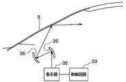
- the head-up display device 30 is disposed inside the instrument panel 70 on the vehicle front side of the air blowing device 10. As shown by an arrow A in FIG. 1, the head-up display device 30 projects a display image including various types of information that supports driving from the inside of the instrument panel 70 toward the windshield 5. This windshield is a windshield 5. Then, the driver recognizes that the image is displayed in front of the windshield 5. The driver can obtain various kinds of information without moving the line of sight greatly by viewing the image superimposed on the situation in front.
- FIG. 2 is a configuration diagram of the head-up display device 30.
- the head-up display device 30 includes a display 32, a control circuit 33, a magnifying glass 35, and a magnifying glass 36.
- the control circuit 33 outputs information for controlling the display device 32 to the display device 32.
- the control circuit 33 is mounted on a control board 33a described later shown in FIG.
- the control circuit 33 generates and generates image information to be displayed on the liquid crystal display unit of the display 32 based on various information such as current position information and vehicle speed information and a signal input from an operation unit provided in the vehicle interior. For example, a process of outputting the obtained image information to the liquid crystal display unit of the display 32 is performed.
- the display 32 projects a display image.
- the display 32 is configured using a liquid crystal display having a liquid crystal display unit and a light source (not shown) that projects light from the back side of the liquid crystal display unit. When light is projected from the back side of the liquid crystal display unit by the light source, the projected light is transmitted through the liquid crystal display and incident on the magnifier 35.
- the magnifying mirror 35 reflects the display image projected from the display device 32, that is, the light, causes the light to enter the magnifying mirror 36, and enlarges the display image.
- the magnifier 35 is arranged at a position where a display image from the display 32, that is, light is incident.
- the magnifying mirror 35 is constituted by a concave mirror called a magnifying mirror.
- the magnifying mirror 36 reflects the display image, that is, the light incident from the magnifying mirror 35, causes the light to enter the windshield 5, and enlarges the display image.
- the magnifying mirror 36 is disposed at a position where a display image from the magnifying mirror 35, that is, light is incident.
- the magnifying mirror 36 is constituted by a concave mirror called a magnifying mirror.
- the display image projected from the display 32 is incident on the magnifying glass 35 and is magnified by the magnifying glass 35. Further, the display image magnified by the magnifier 35 is incident on the magnifier 36, magnified by the magnifier 36, and projected onto the windshield 5.
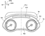
- the air blowing device 10 includes a meter panel 76 including a meter 761 and a meter hood 78 that covers the upper side of the meter panel 76.
- the meter 761 is a speedometer or a tachometer.
- FIG. 3 is a view of the meter panel 76 and the meter hood 78 as seen from the driver 72 in the driving posture with the steering wheel 80 omitted.
- the meter panel 76 includes, in addition to the two meters 761, a meter peripheral portion 762 that constitutes the periphery of the meter 761.
- the meter panel 76 is arranged so that the two meters 761 and the meter peripheral portion 762 can be seen when the meter panel 76 is viewed from the driver's seat 74 side.
- the meter hood 78 is provided so as to expand in the vehicle width direction DR3 above the meter panel 76, that is, above the vehicle, and protrudes rearward of the meter panel 76.
- the meter panel 76 and the meter hood 78 are disposed in front of the driver's seat 74, that is, in front of the driver's seat 74 in the vehicle interior. Further, the steering column 82 protrudes from the portion of the instrument panel 70 below the meter panel 76 toward the driver seat 74. A steering wheel 80 is provided at the tip of the steering column 82.
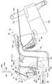
- FIG. 4 is a detailed view of the air blowing device 10 and its neighboring components extracted from FIG. 1 and enlarged.
- FIG. 4 is a view showing a cross section orthogonal to the vehicle width direction DR3 shown in FIG. 3 for the air blowing device 10, the steering wheel 80, and the housing case 40 described later.
- the air blowing device 10 is a device that blows out the blown air from the air conditioning unit 90. That is, the air conditioning unit 90 functions as a blower that sends air to the air blowing device 10.
- the air conditioning unit 90 is a well-known device that is arranged in the instrument panel 70 shown in FIG. 1 and blows out the conditioned air whose temperature is adjusted toward the passenger compartment.
- the air conditioning unit 90 is the same as the indoor air conditioning unit disclosed in Japanese Patent Application Laid-Open No. 2013-082398.
- the air blowing device 10 includes a first air outlet 210 that blows out the air blown from the air conditioning unit 90, a first air outlet door 211, a first duct 21, a first air outlet 210, a second air outlet 220, Two ducts 22 and an air volume adjusting door 23 are provided.
- the 1st blower outlet 210 functions as a face blower outlet which blows off the air cooled by the air conditioner 90 toward a passenger
- the 2nd blower outlet 220 functions as a face opening part which blows off the air cooled by the air conditioner 90 toward the passenger
- the first air outlet 210 is provided integrally with the meter hood 78.
- the 1st blower outlet 210 is opened so that the ventilation air from the air-conditioning unit 90 may be blown off to the vehicle rear.
- the first air outlet 210 opens at the lower side of the meter hood 78.
- the first outlet 210 is opened so that the air blown from the air conditioning unit 90 is blown out to the rear of the vehicle through the inside of the steering wheel 80 as indicated by an arrow FL1.
- the arrow FL1 represents the main flow of the blown air blown from the first outlet 210.
- the main flow of the blown air only needs to reach the driver through the inside of the steering wheel 80, and the entire blown air does not have to pass through the inside of the steering wheel 80.
- the first air outlet door 211 adjusts the direction of air blown from the first air outlet 210.
- the direction of the air blown from the first outlet door 211 changes according to the direction of the first outlet door 211.
- the first duct 21 introduces the blown air from the air conditioning unit 90 to the first air outlet 210. That is, the air blown out from the first air outlet 210 into the vehicle interior is introduced through the first duct 21.
- the second air outlet 220 is an air outlet that blows out air blown from the air conditioning unit 90 in parallel with the first air outlet 210. That is, as shown in FIG. 5, the second air outlet 220 blows air in substantially the same direction as the blown air blown from the first air outlet 210.
- the second air outlet 220 is provided integrally with the first air outlet 210 and is disposed in front of the vehicle with respect to the first air outlet 210.
- the second air outlet 220 opens on the upper surface of the instrument panel 70 of the vehicle so as to face upward, and is disposed in front of the vehicle from the first air outlet 210.
- the second air outlet 220 changes the direction of the air flow blown into the passenger compartment on the same principle as that of the air blowing device described in Japanese Patent Application Laid-Open No. 2014-210564. That is, the 2nd blower outlet 220 changes the airflow which blows off using the Coanda effect toward the vehicle rear.
- the second air outlet 220 has a second air outlet door 220a.
- the second air outlet door 220a adjusts the air flow blown out from the second air outlet 220.
- the second duct 22 introduces the air blown from the air conditioning unit 90 to the second air outlet 220. That is, the air blown out from the second outlet 220 into the vehicle compartment is introduced through the second duct 22.
- the second duct 22 is provided in front of the vehicle with respect to the first duct 21 and behind the housing 31 of the head-up display device 30.
- the air volume adjusting door 23 is an air volume adjusting device that adjusts the flow rate of air introduced into the first duct 21 and the air volume ratio of air introduced into the second duct 22.
- the air volume adjusting door 23 is disposed at a connection position between the first duct 21 and the second duct 22.
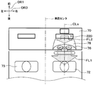
- FIG. 5 is a schematic view of the vehicle front portion in the passenger compartment as viewed from above the vehicle in the present embodiment.
- the main flow of the blown air blown from the first outlet 210 reaches the driver through the inside of the steering wheel 80 as indicated by an arrow FL1.
- the main flow of the blown air blown from the second blower outlet 220 is blown in parallel with the main flow of the blown air blown from the first blower outlet 210 as indicated by an arrow FL2.
- the head-up display device 30 in the present embodiment includes a magnifying glass case 31, a display 32, a control board 33 a on which the control circuit 33 shown in FIG. 2 is mounted, and a control board. 33a and a housing case 40 for housing the heat radiating fins 34.
- the heat radiation fins 34 are projecting portions formed on the control board 33a to radiate heat from the control board 33a.
- the housing 31 is a member that houses the magnifying glass 35 and the magnifying glass 36.
- the housing 31 and the housing case 40 are each configured using a resin (for example, polypropylene).
- the housing case 40 is configured separately from the housing 31.
- the housing case 40 is configured separately from the second duct 22. Further, as shown in FIG. 6, an opening 31 a for projecting a display image is formed on the upper surface of the housing 31.
- the housing case 40 is disposed inside the instrument panel 70 of the vehicle and in front of the second duct 22 of the air blowing device 10.
- the housing case 40 cools the control board 33a and the radiating fins 34 on which the control circuit 33 for controlling the display 32 is controlled by bypassing a part of the air flowing in the second duct 22.
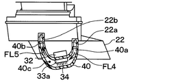
- the housing case 40 has a hollow space 40c in contact with the control board 33a as shown in FIG.
- the hollow space 40 c is a space that accommodates the control board 33 a on which the control circuit 33 that controls the display device 32 is mounted.
- the housing case 40 introduces air that flows in the second duct 22 from the opening 22a of the second duct 22 into the hollow space 40c, and guides the air in the hollow space 40c to the second duct 22. And a communication passage 40b.
- two openings 22a and 22b are formed on the side surface of the second duct 22 in front of the vehicle.
- the opening 22b is formed on the downstream side of the air flow with respect to the opening 22a.
- One end of the communication path 40a is fitted into the opening 22a of the second duct 22, and one end of the communication path 40b is fitted into the opening 22b.
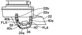
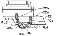
- FIG. 7 is a diagram showing a schematic cross section of the housing case 40.
- a part of the air flowing in the second duct 22 is introduced into the hollow space 40c of the housing case 40 through the communication passage 40a as shown by an arrow FL4 in FIG. 7, and cools the control board 33a and the radiating fins 34. To do. Further, the air introduced into the hollow space 40c of the housing case 40 is introduced into the second duct 22 through the communication path 40b as indicated by an arrow FL5 in FIG.
- the head-up display device 30 When the ignition switch of the vehicle is turned on, the head-up display device 30 is in an operating state, and the control circuit 33 outputs information indicating a display image projected on the windshield 5 to the display 32.
- the display 32 projects a display image based on information input from the control circuit 33. The driver recognizes that the image is displayed at the tip of the windshield 5.
- air is introduced from the air conditioning unit 90 to the first duct 21 and the second duct 22 in accordance with the operation of the occupant.
- the air introduced from the air conditioning unit 90 is introduced into the first duct 21 and the second duct 22 during blowing.
- a part of the air flowing in the second duct 22 is introduced into the hollow space 40c of the housing case 40 through the communication path 40a, and the control board 33a and the radiating fins 34 are caused by the air introduced into the hollow space 40c.
- the air introduced into the housing case 40 is introduced into the second duct 22 through the communication path 40b.
- the head-up display device 30 of the present embodiment can promptly display a display image with high brightness.
- the head-up display device 30 includes the display 32, the control board 33a, and the housing case 40 having the hollow space 40c in contact with the control board 33a.
- the housing case 40 includes communication passages 40a and 40b that connect the duct 22 through which air blown from the air conditioner 90 of the vehicle into the vehicle interior and the hollow space 40c communicate. For this reason, according to the head-up display device 30, it is possible to cool the control circuit 33 that controls the display 32 without providing a cooling fan.
- the display 32 is provided outside the housing case 40, so that it is possible to reduce the reflection of dust on the display image.
- the display device 32 is provided on the outer peripheral surface of the housing case 40, the display device 32 can be cooled by heat conduction of the air flowing in the housing case 40.
- the communication passages 40a and 40b are configured to communicate the second duct through which the air cooled by the air conditioner 90 passes with the hollow space 40c. For this reason, the air cooled by the air conditioner 90 is introduced into the hollow space 40c of the housing case 40 under a high temperature environment such as a summer sun, and the control board 33a and the display 32 can be cooled.
- the housing case 40 of the head-up display device 30 is disposed inside the instrument panel 70 of the vehicle.
- the 2nd duct 22 is a duct which lets air pass through the blower outlet 220 provided so that it might open and open on the upper surface of the instrument panel 70 of a vehicle. That is, in this embodiment, the 2nd duct 22 which blows air to the 2nd blower outlet 220 which blows off the air cooled from the air conditioning unit 90 is arrange
- the head-up display device 30 introduces the air flowing in the second duct 22 into the hollow space 40c from the opening 22a of the second duct 22 and the air in the hollow space 40c.
- a communication passage 40 b leading to the two ducts 22 is provided. That is, as shown in FIG. 7, the head-up display device 30 includes two communication passages 40a and 40b communicating with the second duct 22 and the hollow space 40c. That is, the head-up display device 30 has an opening 22b different from the opening 22a in the second duct 22, and a communication passage 40a communicating with the opening 22a and an opening 22b different from the opening 22a.
- the communication passage 40b communicates with.
- a small flow tributary that is a part of the main flow passes from the opening 22a of the second duct 22 to the communication path 40a. It flows in and passes through the hollow space 40c. And this tributary flows out into the 2nd duct 22 from the opening part 22b.
- a tributary having a smaller flow rate than the main flow flowing through the second duct 22 is passed through the hollow space 40 c and applied to the control board 33 a.
- the control board 33a if the air flowing through the second duct 22, that is, the main flow, is directly applied to the control board 33a, problems such as damage to the control board 33a are likely to occur. However, in the present head-up display device 30, since the tributary flow having a smaller flow rate than the main flow flowing through the second duct 22 is applied to the control board 33a as described above, the control board 33a is disposed without causing a problem when the main flow is applied directly. Can be cooled.
- another communication path that communicates with the second duct 22 and the hollow space 40c may be provided. That is, another opening communicating with the second duct 22 other than the opening 22a and the opening 22b may be formed.
- the housing case 40 is configured to accommodate the control board 33a and have the hollow space 40c in contact with the control board 33a. That is, in the first embodiment, the control board 33a is configured to be accommodated by the hollow space 40c.
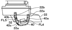
- the control board 33 a is disposed so as to contact the housing case 40 outside the housing case 40. That is, the control board 33a is in contact with the surface of the housing case 40 opposite to the hollow space 40c with the housing case 40 interposed therebetween.
- the housing case 40 has two communication passages 40a that connect the duct 22 through which air blown from the air conditioner 90 of the vehicle into the vehicle interior and the hollow space 40c communicate. , 40b.
- the control circuit 33 that controls the display 32 can be cooled without providing a cooling fan.
- the display 32 is provided outside the housing case 40, it is possible to reduce the appearance of dust on the display image.
- the heat radiating fins 34 may be disposed in contact with the hollow space 40 c. That is, for example, as shown in FIG. 11, a through hole for communicating the outside of the housing case 40 and the hollow space 40 c is formed in the housing case 40, and the heat dissipating fin 34 is formed by passing the heat dissipating fin 34 through the through hole. What is necessary is just to make it contact
- this indication is not limited to the said embodiment, Based on the meaning of this indication, it can implement with a various form.
- the housing case 40 of the above embodiment has the communication path 40a for introducing the air flowing through the second duct 22 from the opening 22a of the second duct 22 into the hollow space 40c, and the air in the hollow space 40c is second.
- a communication path 40 b for introducing the duct 22 is provided.
- the communication path which connects between the 2nd duct 22 and the housing case 40 may be one, and may be three or more. That is, as shown in FIG. 12, in the above-described embodiment, the communication path 40b and the opening 22b may be deleted while leaving the opening 22a and the communication path 40a.
- the opening 22a of the communication path 40a serves as both an air inlet and an outlet to the hollow space 40c of the housing case 40. Therefore, in this case, the configuration of the head-up display device 30 can be simplified.
- a passage 50 may be provided between the housing case 40 and the control board 33a in the hollow space 40c. That is, the blown air FL6 of the second duct 22 that has flowed into the communication path 40a may flow around the control board 33a as indicated by reference numeral FL7 and return to the communication path 40a. In this case, the control board 33a can be efficiently cooled.
- the cooling fin 34 for cooling the control board 33a that is, the heat radiation fin 34
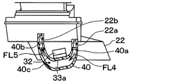
- the cooling fin 34 that is, the heat radiation fin 34 is omitted in the above embodiment as shown in FIG. Also good. Even in this case, the control board 33 a is cooled by the air flowing through the housing case 40.
- the display 32 is configured by a liquid crystal display having a liquid crystal display unit and a light source.
- the display 32 may be configured by using a member other than the liquid crystal display, for example, a fluorescent display tube.
- the hollow space 40c of the housing case 40 and the second duct 22 are configured to communicate with each other.
- the housing case 40 and the second duct 22 are configured separately.
- the housing case 40 and the 2nd duct 22 may be comprised by integral molding, and the housing case 40, the 1st duct 21, and the 2nd duct 22 may be comprised by integral molding. That is, in the above embodiment, the housing case 40 and the second duct 22 may be integrated, or the housing case 40, the first duct 21, and the second duct 22 may be integrated.
- the housing case 40 has the hollow space 40c that houses the control board 33a and is in contact with the control board 33a. That is, the control board 33a is accommodated by the hollow space 40c.
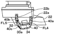
- the control board 33a does not necessarily need to be accommodated in the hollow space 40c. That is, for example, as shown in FIG. 13, in the first embodiment, the housing case 40 is provided with a through hole, the control board 33a is inserted into the through hole, and only a part of the control board 33a enters the hollow space 40c.
- the control board 33a may be disposed so as to come into contact. In this case, the control board 33a can be cooled by being arranged and cooled so that the part of the control board 33a is in contact with the hollow space 40c.
- the indicator 32 is provided outside the housing case 40.
- a part of the display 32 may be provided outside the housing case 40.
- a part of the indicator 32 is provided outside the housing case 40, and a part other than the part of the indicator 32 is provided inside the housing case 40, that is, in the hollow space 40c. May be. Even in this case, the reflection of dust on the display image can be reduced for the part of the display 32 provided outside the housing case 40.
- a recess 51 that is recessed in a direction intersecting the direction from the communication path 40 a toward the communication path 40 b is formed, and the control board 33 a is formed in the recess 51. May be arranged.
- the communication passage 40a is a passage through which air flowing through the second duct 22 is introduced from the opening 22a of the second duct 22 into the hollow space 40c.
- the communication path 40 b is a path that guides the air in the hollow space 40 c to the second duct 22. Even when the control board 33a is arranged in this way, the control board 33a can be cooled because the control board 33a is in contact with the hollow space 40c.
- control board 33a is disposed in the recess 51, the air flow flowing in the order of the communication path 40a, the hollow space 40c, and the communication path 40b does not directly hit the control board 33a. For this reason, it becomes difficult to produce the malfunction of the control board 33a which may arise by this air flow.
Landscapes
- Engineering & Computer Science (AREA)
- Chemical & Material Sciences (AREA)
- Combustion & Propulsion (AREA)
- Transportation (AREA)
- Mechanical Engineering (AREA)
- Physics & Mathematics (AREA)
- General Physics & Mathematics (AREA)
- Optics & Photonics (AREA)
- Instrument Panels (AREA)
Abstract
Description
制御基板と接する中空空間を有するハウジングケースとを備える。表示器は、ハウジングケースの外部に設けられている。制御基板は、ハウジングケースの外部においてハウジングケースに当接するように配置されている。ハウジングケースは、車両の空調装置から車室内へ送風される空気を通すダクトと中空空間とを連通させる連通路を有する。
このヘッドアップディスプレイ装置によっても、冷却ファンを備えることなく表示器を制御する制御回路を冷却することができる。また、このヘッドアップディスプレイ装置では、表示器がハウジングケースの外部に設けられているので、表示像への塵埃の映り込みを低減することもできる。
本開示の第2実施形態について図10を参照して説明する。本実施形態は、第1実施形態に対して、制御基板33aの配置を変更したものであり、その他に関しては第1実施形態と同様であるため、ここでは説明を省略する。
上記した本実施形態の変形例として、図11に示すように、ヘッドアップディスプレイ装置30において、放熱フィン34を中空空間40cに接するように配置しても良い。すなわち、例えば、図11に示すように、ハウジングケース40の外部と中空空間40cとを連通させる貫通孔をハウジングケース40に形成して、該貫通孔に放熱フィン34を通すことで放熱フィン34が中空空間40cに接するようにすれば良い。この場合、より効率的に制御回路33を冷却することができる。
なお、本開示は上記実施形態に限定されるものではなく、本開示の趣旨に基づいて種々なる形態で実施することができる。
Claims (8)
- ヘッドアップディスプレイ装置であって、
車両のウィンドシールドへ表示像を投影する表示器(32)と、
前記表示器を制御する制御回路(33)を搭載した制御基板(33a)と、
前記制御基板を収容し、かつ、前記制御基板と接する中空空間(40c)を有するハウジングケース(40)と、を備え、
前記表示器は、前記ハウジングケースの外部に設けられており、
前記ハウジングケースは、前記車両の空調装置(90)から車室内へ送風される空気を通すダクト(21、22)と前記中空空間とを連通させる連通路(40a、40b)を有するヘッドアップディスプレイ装置。 - ヘッドアップディスプレイ装置であって、
車両のウィンドシールドへ表示像を投影する表示器(32)と、
前記表示器を制御する制御回路(33)を搭載した制御基板(33a)と、
前記制御基板と接する中空空間(40c)を有するハウジングケース(40)と、を備え、
前記表示器は、前記ハウジングケースの外部に設けられており、
前記ハウジングケースは、前記車両の空調装置(90)から車室内へ送風される空気を通すダクト(21、22)と前記中空空間とを連通させる連通路(40a、40b)を有するヘッドアップディスプレイ装置。 - ヘッドアップディスプレイ装置であって、
車両のウィンドシールドへ表示像を投影する表示器(32)と、
前記表示器を制御する制御回路(33)を搭載した制御基板(33a)と、
前記制御基板と接する中空空間(40c)を有するハウジングケース(40)と、を備え、
前記表示器は、前記ハウジングケースの外部に設けられており、
前記制御基板が、前記ハウジングケースの外部において前記ハウジングケースに当接するように配置されており、
前記ハウジングケースは、前記車両の空調装置(90)から車室内へ送風される空気を通すダクト(21、22)と前記中空空間とを連通させる連通路(40a、40b)を有するヘッドアップディスプレイ装置。 - 前記ハウジングケースは、1又は複数個の前記連通路を有する請求項1ないし3のいずれか1つに記載のヘッドアップディスプレイ装置。
- 前記ハウジングケースが、前記ダクトと一体である請求項1ないし4のいずれか1つに記載のヘッドアップディスプレイ装置。
- 前記表示器が、前記ハウジングケースの外周面に設けられている請求項1ないし5のいずれか1つに記載のヘッドアップディスプレイ装置。
- 前記ダクトが、前記空調装置により冷却された前記空気を通す請求項1ないし6のいずれか1つに記載のヘッドアップディスプレイ装置。
- 前記ハウジングケースが、前記車両のインストルメントパネル(70)の内部に配置され、
前記ダクトが、前記車両のインストルメントパネルの上面に、上側を向いて開口するよう設けられた吹出口に前記空気を通すダクトである請求項7に記載のヘッドアップディスプレイ装置。
Priority Applications (4)
| Application Number | Priority Date | Filing Date | Title |
|---|---|---|---|
| DE112016001495.3T DE112016001495B4 (de) | 2015-04-01 | 2016-02-24 | Blickfeldanzeige-Einrichtung |
| CN201680006387.9A CN107206902B (zh) | 2015-04-01 | 2016-02-24 | 平视显示装置 |
| US15/551,063 US10160322B2 (en) | 2015-04-01 | 2016-02-24 | Head-up display device |
| JP2017509384A JP6278155B2 (ja) | 2015-04-01 | 2016-02-24 | ヘッドアップディスプレイ装置 |
Applications Claiming Priority (2)
| Application Number | Priority Date | Filing Date | Title |
|---|---|---|---|
| JP2015075288 | 2015-04-01 | ||
| JP2015-075288 | 2015-04-01 |
Publications (1)
| Publication Number | Publication Date |
|---|---|
| WO2016158100A1 true WO2016158100A1 (ja) | 2016-10-06 |
Family
ID=57007003
Family Applications (1)
| Application Number | Title | Priority Date | Filing Date |
|---|---|---|---|
| PCT/JP2016/055397 Ceased WO2016158100A1 (ja) | 2015-04-01 | 2016-02-24 | ヘッドアップディスプレイ装置 |
Country Status (5)
| Country | Link |
|---|---|
| US (1) | US10160322B2 (ja) |
| JP (1) | JP6278155B2 (ja) |
| CN (1) | CN107206902B (ja) |
| DE (1) | DE112016001495B4 (ja) |
| WO (1) | WO2016158100A1 (ja) |
Cited By (6)
| Publication number | Priority date | Publication date | Assignee | Title |
|---|---|---|---|---|
| WO2019031519A1 (ja) * | 2017-08-08 | 2019-02-14 | 株式会社デンソー | ヘッドアップディスプレイ |
| JP2019031270A (ja) * | 2017-08-08 | 2019-02-28 | 株式会社デンソー | ヘッドアップディスプレイ |
| JP2019217821A (ja) * | 2018-06-15 | 2019-12-26 | 株式会社デンソー | ヘッドアップディスプレイ装置、一体型空調ダクトおよび車両 |
| US10538147B2 (en) | 2015-04-02 | 2020-01-21 | Denso Corporation | Vehicle air condition display device |
| WO2020050044A1 (ja) * | 2018-09-07 | 2020-03-12 | 株式会社デンソー | ヘッドアップディスプレイ装置 |
| JP2020066304A (ja) * | 2018-10-23 | 2020-04-30 | 株式会社デンソー | ヘッドアップディスプレイ装置 |
Families Citing this family (8)
| Publication number | Priority date | Publication date | Assignee | Title |
|---|---|---|---|---|
| JP6582140B2 (ja) * | 2016-09-21 | 2019-09-25 | 富士フイルム株式会社 | 投写型表示装置 |
| US20190182994A1 (en) * | 2017-12-13 | 2019-06-13 | Panasonic Automotive Systems Company Of America, Division Of Panasonic Corporation Of North America | Head up display cooling |
| EP3508399B1 (en) * | 2018-01-09 | 2023-02-22 | Motherson Innovations Company Limited | Self-supporting carrier structure for an instrument panel in a vehicle, instrument panel comprising such a carrier structure and vehicle with such an instrument panel |
| DE102018000151B4 (de) * | 2018-01-11 | 2022-06-15 | Audi Ag | Anzeigevorrichtungsanordnung für ein Fahrzeug |
| JP2020052082A (ja) * | 2018-09-24 | 2020-04-02 | 豊田合成株式会社 | 車載プロジェクタの冷却構造 |
| JP7011568B2 (ja) * | 2018-11-26 | 2022-01-26 | 本田技研工業株式会社 | 車載装置 |
| CN109872646B (zh) * | 2019-03-29 | 2021-08-20 | 凯扬光电(苏州)有限公司 | 一种石墨烯快速散热显示屏 |
| JP7107287B2 (ja) * | 2019-07-26 | 2022-07-27 | 株式会社デンソー | 電子ミラー装置 |
Citations (7)
| Publication number | Priority date | Publication date | Assignee | Title |
|---|---|---|---|---|
| JPH04104724U (ja) * | 1991-02-21 | 1992-09-09 | 日本精機株式会社 | 車両用表示装置 |
| JP2002052957A (ja) * | 2000-08-11 | 2002-02-19 | Denso Corp | ナビゲーションシステムの搭載構造 |
| JP2004196020A (ja) * | 2002-12-16 | 2004-07-15 | Denso Corp | ヘッドアップディスプレイ装置の車両搭載構造 |
| JP2007069771A (ja) * | 2005-09-07 | 2007-03-22 | Denso Corp | 車両用ヘッドアップディスプレイ装置 |
| JP2014091489A (ja) * | 2012-11-06 | 2014-05-19 | Denso Corp | シート用ディスプレイ装置 |
| JP2015020624A (ja) * | 2013-07-19 | 2015-02-02 | トヨタ自動車株式会社 | インストルメントパネル構造 |
| JP2015157575A (ja) * | 2014-02-25 | 2015-09-03 | 日本精機株式会社 | ヘッドアップディスプレイ装置、ヘッドアップディスプレイ装置の冷却システム |
Family Cites Families (12)
| Publication number | Priority date | Publication date | Assignee | Title |
|---|---|---|---|---|
| JPH068748A (ja) | 1992-06-25 | 1994-01-18 | Shimadzu Corp | ヘッドアップディスプレイ |
| US6402321B1 (en) | 1999-10-29 | 2002-06-11 | Delphi Technologies, Inc. | Head up display with modular projection system |
| JP2003118426A (ja) * | 2001-10-16 | 2003-04-23 | Honda Motor Co Ltd | 車両用ヘッドアップディスプレイ装置 |
| JP4270087B2 (ja) * | 2004-09-22 | 2009-05-27 | 株式会社デンソー | ヘッドアップディスプレイ |
| EP2112013A1 (en) * | 2008-04-22 | 2009-10-28 | Mazda Motor Corporation | Instrument Panel Structure and configuration method therefor |
| JP2010134058A (ja) | 2008-12-03 | 2010-06-17 | Nippon Seiki Co Ltd | ヘッドアップディスプレイ装置 |
| JP2010208580A (ja) * | 2009-03-12 | 2010-09-24 | Honda Motor Co Ltd | ヘッドアップディスプレイ装置 |
| US8692739B2 (en) * | 2011-09-22 | 2014-04-08 | GM Global Technology Operations LLC | Dynamic information presentation on full windshield head-up display |
| JP5516544B2 (ja) | 2011-10-12 | 2014-06-11 | 株式会社デンソー | 車両用空調装置 |
| US20140293239A1 (en) * | 2013-03-29 | 2014-10-02 | Funai Electric Co., Ltd. | Projector and head-up display device |
| JP2014210564A (ja) | 2013-04-05 | 2014-11-13 | 株式会社デンソー | 空気吹出装置 |
| JP5962628B2 (ja) | 2013-10-09 | 2016-08-03 | ダイキン工業株式会社 | 空気調和装置 |
-
2016
- 2016-02-24 CN CN201680006387.9A patent/CN107206902B/zh not_active Expired - Fee Related
- 2016-02-24 DE DE112016001495.3T patent/DE112016001495B4/de not_active Expired - Fee Related
- 2016-02-24 US US15/551,063 patent/US10160322B2/en active Active
- 2016-02-24 WO PCT/JP2016/055397 patent/WO2016158100A1/ja not_active Ceased
- 2016-02-24 JP JP2017509384A patent/JP6278155B2/ja not_active Expired - Fee Related
Patent Citations (7)
| Publication number | Priority date | Publication date | Assignee | Title |
|---|---|---|---|---|
| JPH04104724U (ja) * | 1991-02-21 | 1992-09-09 | 日本精機株式会社 | 車両用表示装置 |
| JP2002052957A (ja) * | 2000-08-11 | 2002-02-19 | Denso Corp | ナビゲーションシステムの搭載構造 |
| JP2004196020A (ja) * | 2002-12-16 | 2004-07-15 | Denso Corp | ヘッドアップディスプレイ装置の車両搭載構造 |
| JP2007069771A (ja) * | 2005-09-07 | 2007-03-22 | Denso Corp | 車両用ヘッドアップディスプレイ装置 |
| JP2014091489A (ja) * | 2012-11-06 | 2014-05-19 | Denso Corp | シート用ディスプレイ装置 |
| JP2015020624A (ja) * | 2013-07-19 | 2015-02-02 | トヨタ自動車株式会社 | インストルメントパネル構造 |
| JP2015157575A (ja) * | 2014-02-25 | 2015-09-03 | 日本精機株式会社 | ヘッドアップディスプレイ装置、ヘッドアップディスプレイ装置の冷却システム |
Cited By (7)
| Publication number | Priority date | Publication date | Assignee | Title |
|---|---|---|---|---|
| US10538147B2 (en) | 2015-04-02 | 2020-01-21 | Denso Corporation | Vehicle air condition display device |
| WO2019031519A1 (ja) * | 2017-08-08 | 2019-02-14 | 株式会社デンソー | ヘッドアップディスプレイ |
| JP2019031270A (ja) * | 2017-08-08 | 2019-02-28 | 株式会社デンソー | ヘッドアップディスプレイ |
| JP2019217821A (ja) * | 2018-06-15 | 2019-12-26 | 株式会社デンソー | ヘッドアップディスプレイ装置、一体型空調ダクトおよび車両 |
| WO2020050044A1 (ja) * | 2018-09-07 | 2020-03-12 | 株式会社デンソー | ヘッドアップディスプレイ装置 |
| JP2020040468A (ja) * | 2018-09-07 | 2020-03-19 | 株式会社デンソー | ヘッドアップディスプレイ装置 |
| JP2020066304A (ja) * | 2018-10-23 | 2020-04-30 | 株式会社デンソー | ヘッドアップディスプレイ装置 |
Also Published As
| Publication number | Publication date |
|---|---|
| US20180093567A1 (en) | 2018-04-05 |
| DE112016001495B4 (de) | 2021-09-16 |
| JPWO2016158100A1 (ja) | 2017-08-03 |
| CN107206902A (zh) | 2017-09-26 |
| CN107206902B (zh) | 2019-08-30 |
| US10160322B2 (en) | 2018-12-25 |
| JP6278155B2 (ja) | 2018-02-14 |
| DE112016001495T5 (de) | 2018-01-04 |
Similar Documents
| Publication | Publication Date | Title |
|---|---|---|
| JP6278155B2 (ja) | ヘッドアップディスプレイ装置 | |
| JP6642706B2 (ja) | 空気吹出装置 | |
| JP6443188B2 (ja) | 車両空調用表示装置 | |
| EP3528043B1 (en) | Projector and head-up display device including projector | |
| WO2016121269A1 (ja) | 車両用ヘッドアップディスプレイ装置 | |
| WO2018030022A1 (ja) | 空気吹出装置 | |
| US20180251012A1 (en) | Vehicular defroster duct structure | |
| JP2020052082A (ja) | 車載プロジェクタの冷却構造 | |
| JP6729631B2 (ja) | ヘッドアップディスプレイ | |
| JP4270087B2 (ja) | ヘッドアップディスプレイ | |
| JPH1134652A (ja) | 自動車用空調装置の吹き出し口グリル | |
| JP6996906B2 (ja) | 空調装置、及び、ワイヤハーネス | |
| JP2018090200A (ja) | 送風装置 | |
| KR102021372B1 (ko) | 자동차의 에어 벤트 구조 | |
| JP6551526B2 (ja) | 空気吹出装置 | |
| JP3945232B2 (ja) | ヘッドアップディスプレイの車両搭載構造 | |
| JP6065817B2 (ja) | 車室内温度検出モジュール及びこれを備えた車両用空調装置 | |
| CN117507816B (zh) | 抬头显示设备及车辆 | |
| JP2016016852A (ja) | インストルメントパネル構造 | |
| JP2019217821A (ja) | ヘッドアップディスプレイ装置、一体型空調ダクトおよび車両 | |
| WO2016158555A1 (ja) | 車室前部構造 | |
| WO2019031519A1 (ja) | ヘッドアップディスプレイ | |
| JP6996905B2 (ja) | 空調装置、及び、ワイヤハーネス | |
| JP2020066304A (ja) | ヘッドアップディスプレイ装置 |
Legal Events
| Date | Code | Title | Description |
|---|---|---|---|
| 121 | Ep: the epo has been informed by wipo that ep was designated in this application |
Ref document number: 16771984 Country of ref document: EP Kind code of ref document: A1 |
|
| ENP | Entry into the national phase |
Ref document number: 2017509384 Country of ref document: JP Kind code of ref document: A |
|
| WWE | Wipo information: entry into national phase |
Ref document number: 15551063 Country of ref document: US |
|
| WWE | Wipo information: entry into national phase |
Ref document number: 112016001495 Country of ref document: DE |
|
| 122 | Ep: pct application non-entry in european phase |
Ref document number: 16771984 Country of ref document: EP Kind code of ref document: A1 |